Zamo - Laser level BOSCH - Free user manual and instructions
Find the device manual for free Zamo BOSCH in PDF.
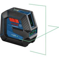
| Product Type | Laser level with digital rangefinder and adapters |
| Brand | Bosch |
| Model | Zamo |
| Rangefinder Dimensions | 105 x 38 x 22 mm |
| Rangefinder Weight | 0.08 kg (according to EPTA-Procedure 01:2014) |
| Power Supply | 2 AAA (LR03) 1.5 V batteries |
| Measuring Range | 0.15 m to 20 m (typical) |
| Measurement Accuracy | ±3.0 mm (typical) |
| Laser Class | 2 |
| Laser Type | Red laser 635 nm, <1 mW |
| Operating Temperature | -10°C to +40°C |
| Storage Temperature | -20°C to +70°C |
| Battery Life (measuring mode) | approx. 5 h |
| Display | Screen with measurement values and indicators (battery, temperature, adapter, laser) |
| Main Functions | Distance measurement, lengths, heights, spacings; area calculation; with adapters: line alignment, tape measurement, wheel measurement |
| Laser Line Adapter | Dimensions: 38 x 40.5 x 22.3 mm, weight: 0.02 kg, accuracy ±1 mm/m, opening angle ≥28°, fine adjustment ±10° |
| Tape Adapter | Dimensions: 38 x 33.5 x 22.3 mm, weight: 0.03 kg, measuring range 0.005–1.5 m, accuracy ±1.0 mm/m |
| Wheel Adapter | Dimensions: 38 x 48 x 22.3 mm, weight: 0.02 kg, max range 20 m, accuracy ±5.0 mm/m |
| Safety | Do not point the beam at eyes or animals; laser class 2; do not look directly into the beam |
| Maintenance | Clean with a soft, damp cloth; do not immerse in water; do not use solvents |
| Spare Parts | Available through Bosch after-sales service (10-digit reference on the rating label) |
| After-Sales Service | France: 0811360122, Belgium: +32 25880589, Switzerland: 044 8471512; Email: contact.outillage-electroportatif@fr.bosch.com |
Frequently Asked Questions - Zamo BOSCH
User questions about Zamo BOSCH
0 question about this device. Answer the ones you know or ask your own.
Ask a new question about this device
Download the instructions for your Laser level in PDF format for free! Find your manual Zamo - BOSCH and take your electronic device back in hand. On this page are published all the documents necessary for the use of your device. Zamo by BOSCH.
USER MANUAL Zamo BOSCH
YkpaHcbka .CtopiHa 290
Ka3ak... 5et 307
All instructions must be read and observed in order for the measuring tool to function safely. The safeguards integrated into the measuring tool may be compromised if the measuring tool is not used in accordance
with these instructions. Never make warning signs on the measuring tool unrecognisable. SAVE THESE INSTRUCTIONS FOR FUTURE REFERENCE AND INCLUDE THEM WITH THE MEASURING TOOL WHEN TRANSFERRING IT TO A THIRD PARTY.
Do not use the measuring tool in explosive atmospheres which contain flammable liquids, gases or dust. Sparks may be produced inside the measuring tool, which can ignite dust or fumes.
The measuring tool is delivered with a warning sign (marked in the illustration of the measuring tool on the graphics page).
If the text on the warning label is not in your native language, cover it with the label supplied, which is in your language, before initial commissioning.

Do not direct the laser beam at persons or animals and do not look directly into the laser beam or at its reflection. Doing so could lead to blindless, or could cause accidents or damage to the eyes.
If laser radiation hits your eye, you must close your eyes and immediately turn your head away from the beam.
Do not make any modifications to the laser equipment.
Never leave the measuring tool unattended when switched on, and ensure the measuring tool is switched off after use. Others may be dazzled by the laser beam.
Have the measuring tool serviced only by a qualified specialist using only original replacement parts. This will ensure that the safety of the measuring tool is maintained.
Do not let children use the laser measuring tool unsupervised. They could accidentally dazzle someone.
Do not use the laser goggles as protective goggles. The laser goggles make the laser beam easier to see; they do not protect you against laser radiation.
Do not use the laser goggles as sunglasses or while driving. The laser goggles do not provide full UV protection and impair your ability to see colours.
Warning! If operating or adjustment devices other than those specified here are used or other procedures are carried out, this can lead to dangerous exposure to radiation.
Product description and specifications
Intended Use
Digital laser measure
The measuring tool is intended for measuring distances, lengths, heights and clearances, and for calculating areas. The measuring tool is suitable for measuring indoors.
28|English
Laser line adapter
The laser line adapter is intended to be used in combination with the Zamo digital laser measure for vertical or horizontal alignment (e.g. of wall pictures) in interior areas.
Tape adapter
The tape adapter is intended for use in combination with the Zamo digital laser measure for measuring circumferences (e.g. of vases, pipes, etc.) and lengths of freestanding objects (e.g. televisions, shelves, etc.) in interior areas.
Wheel adapter
The wheel adapter is intended for use in combination with the Zamo digital laser measure for measuring distances between two points (e.g. lengths of material) in interior areas.
Product features
The numbering of the product features shown refers to the illustration of the measuring tool on the graphic page.
(1) Measuring button
(2) Display
(3) Battery compartment cover
(4) Locking mechanism of the battery compartment cover
(5) Serial number
(6) Laser warning label
(7) Reception lens
(8) Laser beam output
(9) Cover cap
(10) Release buttons for adapter
Display elements
(a) Battery warning
(b) Temperature warning
(c) Fitted adapter
(d) Laser switched on
(e) Previous measured value
(f) Unit of measurement
(g) Current measured value
(h) Area measurement
Laser line adapter A)
(11) Level for vertical alignment
(12) Level for horizontal alignment
Tape adapter A)
(13) Tape
(14) Contact edge
Wheel adapter A)
(15) Wheel
A) Accessories shown or described are not included with the product as standard.
Technical data
| Digital laser measure Zamo | |
| Article number 3 603 F72 7.. | |
| Measuring range (typical) 0.15–20.00 m | |
| Measuring accuracy (typical) | ±3.0 mm |
| Smallest display unit 1 mm | |
| Measuring time | |
| - typical 0.5 s | |
| - maximum 4.15 s | |
| Operating temperature -10 °C to +40 °C | |
| Storage temperature -20 °C to +70 °C | |
30 | English
Digital laser measure Zamo
| Altitudes up to 2000 m | |
| Max. relative humidity 90% | |
| Degree of pollution A) | 2 |
| Laser class 2 | |
| Laser type 635 nm, < 1 mW | |
| Laser beam diameter (at 25 °C) ap- prox. | |
| - 10 m distance 9 mm | |
| - 20 m distance 18 mm | |
| Batteries 2 x 1.5 V LR03 (AAA) | |
| Battery life during measuring opera- tion approx. | 5 h |
| Weight according to EPTA-Proced- ure 01:2014 | 0.08 kg |
| Dimensions 105 x 38 x 22 mm |
A) non-conductive pollution only, whereby occasional temporary conductivity caused by condensation is expected
Note on measuring range: In unfavourable conditions, e.g. with extremely bright interior lighting or a poorly reflecting surface, the measuring range may be reduced.
Note on measuring accuracy: In unfavourable conditions, e.g. with extremely bright interior lighting, a poorly reflecting surface or a room temperature that deviates significantly from 25^ , the deviation can be a maximum of +/-8mm at a distance of 20m . In favourable conditions, a deviation of +/-0.05mm/m needs to be taken into account.
Adapter
Operating temperature - 10^ to +40^
Storage temperature -20°C to +70°C
1609 92A 454 | (14.06.2018) Bosch Power Tools
English | 31
| Adapter | |
| Max. relative humidity 90% | |
| Degree of pollutionA) | 2 |
| Laser line adapter Line Adapter | |
| Article number 1608 M00 C22 | |
| Laser line widthB) at 2 m distance ≤ 2.0 mm | |
| Laser line lengthB) at 2 m distance ≥ 1 m | |
| Measuring accuracy (typical at 25 °C) | ±1 mm/m |
| Opening angle ≥ 28° | |
| Angle for fine adjustment ± 10° | |
| Weight according to EPTA-Proced-ure 01:2014 | 0.02 kg |
| Dimensions 38 x 40.5 x 22.3 mm | |
| Tape adapter Tape Adapter | |
| Article number 1608 M00 C26 | |
| Measuring accuracy (typical at 25 °C) | ±1.0 mm/m |
| Measuring range 0.005–1.5 m | |
| Weight according to EPTA-Proced-ure 01:2014 | 0.03 kg |
| Dimensions 38 x 33.5 x 22.3 mm | |
| Wheel adapter Wheel Adapter | |
| Article number 1608 M00 C24 | |
| Measuring accuracy (typical at 25 °C) | ±5.0 mm/m |
| Measuring range (max.) 20 m | |
32 | English
Adapter
Weight according to EPTA-Procedure 01:2014
0.02 kg
Dimensions 38 × 48 × 22.3 ~mm
A) non-conductive pollution only, whereby occasional temporary conductivity caused by condensation is expected
B) depending on surface characteristics and ambient conditions
Digital laser measure
Inserting/changing the batteries
It is recommended that you use alkaline manganese batteries to operate the measuring tool.
- Insert the batteries (see figure on page 4). When inserting the batteries, ensure that the polarity is correct according to the illustration on the inside of the battery compartment.
The battery warning (a) is shown on the display when the battery voltage is weakening.
When the battery symbol first appears on the display, measurements can be made for approx. another 15 minutes. When the battery symbol flashes, you have to replace the batteries because measurements are no longer possible.
Always replace all the batteries at the same time. Only use batteries from the same manufacturer and which have the same capacity.
Do not use lithium-ion batteries. This may result in damage to the measuring tool.
Operation
Switching the laser measure on/off
- To switch on the measuring tool, briefly press the measuring button (1). When the measuring tool is switched on, the laser beam is switched on. The indicator ^ flashes on the display.
- To switch off the measuring tool, hold down the measuring button (1).
Measuring process
A continuous measurement is performed after the measuring tool has been switched on. The current measured value (g) is shown on the bottom line of the display (see figure A). During continuous measurement, the measuring tool can be moved relative to the target and the current measured value (g) will be updated approx. every 0.5 seconds on the bottom line of the display (see figure B). The indicator ^* flashes on the display.
The rear edge of the measuring tool is the reference level for the measurement ( ). (See figure C)
Measuring length
- Press the measuring button (1) to stop the measuring process. The laser beam is switched off and the current measured value (g) is displayed.
- Press the measuring button (1) again to switch the laser back on and continue measuring. The current measured value (g) is shown on the bottom line of the display, while the previous measured value (e) is displayed above it.
Area measurement
- Press the measuring button (1) twice in quick succession to multiply the last two measurements together (see figure D). The indicator appears on the display and the area measurement is shown.
34|English
Press the measuring button (1) twice in quick succession again to display the last two measurements.
If no button on the measuring tool is pressed for approx.
5 mins, the measuring tool will automatically switch itself off to preserve battery life.
- Do not direct the laser beam at persons or animals and do not stare into the laser beam yourself (even from a distance).
Practical advice
General advice
The reception lens (7) and the laser beam output (8) must not be covered during the measuring process.
The measurements are taken at the centre of the laser beam, even when the laser is pointed at surfaces diagonally.
Errors - causes and corrective measures
Cause Corrective measure
Temperature warning (b) flashing, display shows "err", measurement not possible, measuring tool switches off automatically after five seconds
Measuring tool is outside of the operating temperature range of -10^ to +40^ .
Wait until the measuring tool has reached operating temperature. Then switch the measuring tool back on.
All symbols flash, measurement not possible
Measuring tool faulty Check the batteries and replace them if necessary.
Fitted adapter (c) flashes, display shows "err", measurement not possible
Adapter error:
Cause Corrective measure
| -Faulty adapter Send the adapter to the after-sales service. | |
| -Adapter has no connection to the measuring tool | Clean the contacts. If the adapter still cannot connect to the measuring tool after you have done this, send the adapter to the after-sales service. |
| Display shows “----”, measurement not possible | |
| Measuring range exceeded (20 m) or poor measuring conditions | Keep the measuring range <20 m and read the notes on the measuring range |
Fitting the Adapter (see figures E, H, J)
- Remove the cover cap (9) from the measuring tool.
- Attach the adapter to the laser measure so that it clicks into place.
- To remove the adapter, press the release buttons (10) and take off the adapter.
- Reattach the cover cap to the measuring tool.
Digital laser measure with laser line adapter
Operation
Activating the laser line
- Switch on the measuring tool (see "Switching the laser measure on/off", page 33).
-
To show the laser line, briefly press the measuring button (1). The indicator ^ 喜 flashes on the display.
-
Do not direct the laser beam at persons or animals and do not stare into the laser beam yourself (even from a distance).
Note: If the measuring tool is switched on when fitting the adapter, the laser will automatically switch off. Pressing the measuring button (1) will reactivate the laser line.
Aligning the laser line
-
Align the laser line with the level for horizontal alignment (12) (see figure F) or the level for vertical alignment (11) (rotate the measuring tool by 90^ ) (see figure G). The bubble must be in the centre of the level vial.
-
To precisely align the laser line, you can turn the adapter head by ± 10^ around the laser line.
Note: Make sure that the measuring tool is always positioned horizontally in order to obtain an exact measurement. You can adjust the height of the laser line by placing suitable objects underneath (e.g. a ladder, books, etc.).
Digital laser measure with tape adapter
Operation
- Switch on the measuring tool (see "Switching the laser measure on/off", page 33).
Only use the tape adapter on clean and dust-free surfaces to avoid measurement inaccuracies.
Measuring length (see figures I1-I2)
After the measuring tool has been switched on, the tape extension is measured continuously. The current measured value (g) is shown on the bottom line of the display. During continuous measurement, the length of the tape can be adjusted, and the current measured value (g) is updated on the bottom line of the display.
The measuring process is indicated by a rolling arrow on the display.
- Pull the tape (13) out of the adapter by the contact edge (14) and place the tape against the object to be measured. The visible length of tape (between the two red markings) corresponds to the measurement length (in cm).
- Press the measuring button (1) to save the measured value. The current measured value (g) is shown on the bottom line of the display. Press the measuring button (1) again to start a new measurement. The current measured value (g) is shown on the bottom line of the display, while the previous measured value (e) is saved and shown on the top line of the display.
Note: When switching off the measuring tool, the current measured value (g) is reset to "0", even if the tape is still pulled out. To avoid measuring errors, always retract the tape fully before taking a new measurement. Do not press the
38 | English
measuring button until you have done this.
If the tape is already extended when you are fitting the adapter to the measuring tool or switching on the measuring tool, the "roll in" indicator will appear on the display. Retract the tape fully and press the measuring button before taking a new measurement.
Always make sure that the measuring tape does not snap back into the adapter. Release the tape slowly back into the adapter; otherwise it may become damaged.
Area measurement
- Press the measuring button (1) twice in quick succession to multiply the last two measurements together. The indicator appears on the display and the area measurement is shown.
Digital laser measure with wheel adapter
Operation
- Switch on the measuring tool (see "Switching the laser measure on/off", page 33).
Measuring Length (see figures K1-K2).
- Run the wheel (15) along the distance to be measured. After the measuring tool has been switched on, the wh measures continuously. The current measured value (s shown on the bottom line of the display.
During continuous measurement, the wheel can be moved forwards or backwards. The measured values will be positive in both directions. If the direction is changed during the measurement, the value will be deducted until the starting point (zero point) has been reached. Once the starting point has been crossed, the value will become positive
again.
The current measured value (g) is updated on the bottom line of the display.
- The measuring process ends once the wheel has come to a stop. The current measured value (g) is shown.
- Press the measuring button (1) again to save the measured value, and continue measuring. The current measured value (g) is shown on the bottom line of the display, while the previous measured value (e) is displayed above it.
Note: In order to obtain an exact measurement, do not change the angle between the measuring tool and the surface (see figure L). Make sure that you apply a steady amount of pressure throughout the measuring process. The result may vary on soft substrates and/or when applying excessive pressure. The recommended pressure for an exact measurement result is 500 g.
Area measurement
- Press the measuring button (1) twice in quick succession to multiply the last two measurements together. The indicator appears on the display and the area measurement is shown.
Maintenance and Servicing
Maintenance and cleaning
Keep the measuring tool clean at all times.
Never immerse the measuring tool in water or other liquids. Wipe off any dirt using a damp, soft cloth. Do not use any detergents or solvents.
Take particular care of the reception lens (7), which must be handled with the same level of care you would give to a pair of glasses or a camera lens.
40 | English
Send in the measuring tool if it requires repair.
After-sales service and advice on using products
Our after-sales service can answer questions concerning product maintenance and repair, as well as spare parts. You can find exploded drawings and information on spare parts at:
www.bosch-pt.com
The Bosch product use advice team will be happy to help you with any questions about our products and their accessories. In all correspondence and spare parts orders, please always include the 10-digit article number given on the type plate of the product.
Great Britain
Robert Bosch Ltd. (B.S.C.)
P.O.Box 98
Broadwater Park
North Orbital Road
Denham Uxbridge
UB95HJ
At www.bosch-pt.co.uk you can order spare parts or arrange the collection of a product in need of servicing or repair.
Tel. Service: (0344) 7360109
E-Mail: boschservicecentre@bosch.com
Ireland
Origo Ltd.
Unit 23 Magna Drive
Magna Business Park
City West
Dublin 24
Tel. Service: (01) 4666700
Fax: (01) 4666888
Australia, New Zealand and Pacific Islands
Robert Bosch Australia Pty. Ltd.
Power Tools
English | 41
Locked Bag 66
Clayton South VIC 3169
Customer Contact Center
Inside Australia:
Phone: (01300) 307044
Fax: (01300) 307045
Inside New Zealand:
Phone: (0800) 543353
Fax: (0800) 428570
Outside AU and NZ:
Phone: +61 395415555
www.bosch-pt.com.au
www.bosch-pt.co.nz
Republic of South Africa
Customer service
Hotline: (011) 6519600
Gauteng - BSC Service Centre
35 Roper Street, New Centre
Johannesburg
Tel.: (011) 4939375
Fax: (011) 4930126
E-mail: bsctools@icon.co.za
KZN - BSC Service Centre
Unit E, Almar Centre
143 Crompton Street
Pinetown
Tel.: (031) 7012120
Fax: (031) 7012446
E-mail: bsc.dur@za.bosch.com
Western Cape - BSC Service Centre
Democracy Way, Prosperity Park
Milnerton
Tel.: (021) 5512577
Bosch Power Tools 1609 92A 454 | (14.06.2018)
42 | English
Fax: (021) 5513223
E-mail: bsc@zsd.co.za
Bosch Headquarters
Midrand, Gauteng
Tel.: (011) 6519600
Fax: (011) 6519880
E-mail: rbsa-hq.pts@za.bosch.com
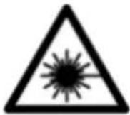
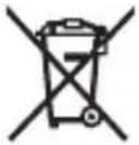
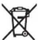
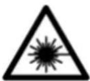
Disposal
Measuring tools, accessories and packaging should be recycled in an environmentally friendly manner.
Do not dispose of measuring tools or batteries with household waste.
Only for EU countries:
According to the Directive 2012/19/EU, measuring tools that are no longer usable, and according to the Directive 2006/66/ EC, defective or used battery packs/batteries, must be collected separately and disposed of in an environmentally correct manner.
Français
Robert Bosch (France) S.A.S.
Calle Robert Bosch No. 405
C.P. 50071 Zona Industrial, Toluca - Estado de Mexico
Tel.: (52) 55 528430-62
Tel.: 800 6271286
Bosch Service Center
Telegrafvej 3
2750 Ballerup
Bosch Service Center
Telegrafvej 3
2750 Ballerup
Danmark
Tel.: (08) 7501820 (inom Sverige)
Fax: (011) 187691
Avfallshantering
Piopaaoyeaacakivwv aeepA)
Euoypaumn nca ktrivaac leizep
Eunnpetnon nclawv kal ououc eapoyic
H unnpoeia eunnpetnonc neaawv anavra otic epwnoeic oac oxetka me tnv eniakeun kai tn ouvtipnon tou npoiovtoc aoc kaowc kai yia ta avtioya avtaalaktka. xedia ouvapmooyonc kai nnpoopiec yia ta avtaalaktka tha bpeite enionc katw ano: www.bosch-pt.com
Eλληνικα | 193
H ouδa napoxh cououw Tnc Bosch anavta euyapiotwc tic epwtnoeioc aac yia ta npoiovta mac kal ta eapntmuata touc.
kai npayveiec avtaaakikov onoohnote tov 10nphiio kwdiok apiOo ouwpwa ie tny nivakiia tunou tou npoiovtoc.
EAAδa
Robert Bosch A.E.
Epxicac 37
19400 Kopomega-Ahva
Tnλ: 2105701258
Φaξ: 2105701283
www.bosch.com
www.bosch-pt.gr
ABZ Service A.E.
Tnλ: 2105701380
Φaξ:2105701607
Anòoupon
Ta opyava etpnonc, ta eapntmaata kal oI ouokeuaoeic npenei va avakukawovtai me tpoTO piko TPOC TO nepiaaov.
Mn pixvete ta opyava metpnonc kal tic mntapiec ota oikiaka anoppipmuata!
Movi yia xwpec tnc EE:
Robert Bosch Sp. zo.o.
Bosch Service Center PT
K Vapence 1621/16
692 01 Mikulov
Na www.bosch-pt.cz si si muzete objednat opravu Vaseho stroje nebo nahradni dily online.
Lézervonal-adapter Line Adapter
PekomeHnyetcOuHCTnTb HNCTpyMeHT OT nbIIN NOcNe KaJIOrO NcNoJIb3OBaHn.
XpaheHne
-Heo6xOdHMo XpaHnTb BCyXOM MecTe
- Heo6xOJIMO XpaHHTb BdaJIH OT ICTOCHIKOB IOBblIeHHbIX TeMnepaTpN BO3dEhCTBnA COJIHeuHbIX Lyuei
-Приханени Heo6xodmo n36eRaTb pe3KOrO nepenada TemnepaTyP
-xpaheHHe 6e3 ynaKOBKn He dOnyckKaetcA
-fnoopobhble tpe6oBaHnK yCIOBnM XpaHeHn CMOtpnte BTOCT 15150 (YcNoBne 1)
TpaHcnpToPbKa
- KaTeOpnueckn He DoynyckaetcnaeHne n IIObIe MexaHnueckne BO3dEiCTBnHa yNaKOBky npN TpaHCnpTIpOBKe
- npn pa3rpy3ke/npry3ke He dOnyckaetc HcNoIb3OBaHne IIO6Oro BnDa TexHnKn, pa6oTaIoUeN No npnHunny 3axnMa yNaKOBKn
- noДрбны.Tpe6OBaHЯ K yCNoBnA M TpaHcNoptHnpOBKn CMOTpIte B FOCT 15150 (YcNoBne 5)
Yka3aHnI NO TexHnke 6e30nacHOCTN

Дя obecneueHЯ 6e3oNaChOH n HadexHON pa6OtbI c H3MepTeHbHbIM HHCTpyMeHTOMdoJXHbI 6bITb npouHTaHbINco6JIIOdaTbcra BCE HHCTpyKcHH. HcNoIb30BaHHe H3MepTeHbHO HHCTpyMeHTa He B
COOTBETCTBHN C HAcTOnaUHmN yKa3aHnA M NpeBaTO NOBpeXDeHnem HHTerpnpoBaHHbIX 3aunTHbIX MexAHn3MOB. HnKOrda He n3MeHnTe Do Hey3HaBaemocTN ppeynpeHnTeNbHbIe Ta6nucn Ha n3MePnteJbHom HHcTpymente. XOPoIco COxPAHNTE 3TN HHCTpyKuIN N IPEPaABaIteNX BMECTEC INPEDAUeN3MEPHTeJIbHOHO IHCTPYMEHTA.
He pa6oTaTe c n3MePHTeNbHbIM HnCTpyMeHTOM BO B3pbIBOONaCHOcpe, no6n3OCTn OT rOpUHX KNDKOCTe, ra3OB n nbIN. B n3MePHTeNbHOM HnCTpyMeHTe MOryT o6pa3OBaTbcra NCKpbl, OT KOToPbIX MOxET BOCnJaMeHNtbcra nbIn nn Napbl.
H3MepnteBHyINHCTpyMeHT NOCTaBnAETC npeDynpdInTeBHO Ta6nukO (NOKa3aHa Ha cTpaHnCe C N306paXeHNEm H3MepnteBHO INHCTpyMeHTa).
Ecn TeKCT npedynpeHntbHOJ Ta6nukn He Ha BaWem podHom 3bIke, nepe nepBbIM 3anyckOM B 3KcnpyaTa- zuo 3akneTe ee haknekoH na BaWem podHom 3bIke, KOTOPa BXOHT BObem NOCTABKN.

He hampabnnte lyu na3epa ha IIOe Hnn XNBOTbIX n cam He CMOTpTe Ha npmoH nn OTPaxaemblny na3epa. 3TOT nyu MoXeT cIeNTb IIOe, CTAb npuHOn HeCcuactHO rO cnuya Hn IOBpeNTb rna3a.
B cnyuae nonaahanna na3epnoro lyuab rna3 rna3a hyxHo HamepeHHO 3akpbItb HemeJeHHO OTBepHyTbCnOT nyua.
274|Pycckn
He meHnTe HnUero B Ia3epHom yCTpoNCTBe.
He octablaIte H3MepHTeIbHbI HNCTpyMeHT 6e3 npHcMoTpa H BbIKIOuAte H3MepHTeIbHbI HNCTpyMeHT NOcne HcNoIb30BaHn.ДpyrIe INuca MoryT 6bITb OcJIeIIeHbI Na3ePHbIM LyUOM.
PemOHn3MepHTeNbHOrO HNCTpyMeHtpa3peWaeTc BbINoHNaTb TOnbKO KBAHnΦHnpuOBaHHOMy NepcoHaNy n ToIbKO C HCNoJIb30BaHHem OPHRnHaNbHbIX 3aNaCTe. 3TNm oBeCneuHBaETcBbe3ONaCHOCTb H3MepHTeNbHO rHCTpyMeHtA.
He no3B0JaIe DeTAM nOlb30BaTbCra Ia3epHbIM H3Me- pHTeJIbHbIM HnCTpyMeHToM 6e3 npncMoTpA. TeN MoTy NO HeoctopoXHOCTN OcIeNTb IOCTOpOHNX IIOJeN.
He nCnoB3yIe ouKn dIpa6OtbI c na3epoM B KaueCTBe 3aunTHbIX OUKOB. OuKn dIpa6OtbI c na3epoM o6ecneuBaIOT lyuwee paCnO3HaBaHne na3epHOrO lyua, Ho He 3aunlaIOT OT na3epHOrO n3nyeHn.
He nCnoB3yIte ouKn dJa pa6oTbI c Na3epom B KaueCTBe coHnue3aunTHbIX ouKOB HnN 3a pyJeM. Oukn dJa pa6oTbIC Ja3epom He oBeCneuBaIoT 3aunTy ot YΦ-n3nyueHn I Me7aIoT npaBnBHomU ZBEtOBOcPnAITNo.
Octopoxho - npimehene HnHctpymeHTOB nna 06nyKHBaHHn HnIOCTnpOBKn Hn npoecdyp Texo6cnyXbAHn, Kpome yka3aHHbIX 3decb, MoKeT npHBecTN K onacHomy B03dEChTBnIO H3nyeHHn.
Описане прodyкту услуг
PpimHeHne no Ha3haueHHIO
UΦpOBoIa3epHbI N3MepHTeIb paCCToHnI
I3mepntbHbI HnCTpyMeHT npedHa3NaueH IJIy I3MepenpaacctOHH, DIIH, BbICOT, ydaJeHH n paCye Ta PLOaJe.
I3mepntbHbI INHCTpyMeHT npnroeH dIpa60tBHytpn Iomeuhen.
Aanterp na3epno nnnn
AdaTep Ia3epHoi IHHn BMeCTe C uOpOBbIM Ia3epHbIM H3-MepnteIem pacCToHnzaMo npEHa3NaueH dIy BbipABHnBa-HnnoBepTKaII nIIN rOpN3OHTaII (HaNP., KapTHN) B NOME-
IeHTouHbI aanTep
IeHTouhbl aadantep BmecTe C uHpOBbIM na3epHbIM n3MepeTeneM pacctoHHa ZAmo npedHa3haueH dIy n3MepeHHaXbATOB (HaNP., Ba3, Tpy6 nT.D.) nDnH OTdEJIbHOCTOaHX 06BeKToB (HaNP., TeNEBn3OpOB, NOnOK nT.D.) B NOMEeHHx.
PonKobin aanTep
PonkoBbI aanTep BmecTe c uOPOBbIM Ia3epHbIM n3MepeH Telem pacctoHnzaMo npEHa3HaueH dJa n3MepeHn OTe3KOB MeJy DByMa TOUkAmn (HaNP., nnHb ITkaH) B NOMEuHEHX.
CnfoBoN Ia3epHbI N3Mepntelb paCCTOHNIA
Bctabka/3ameha 6atapeek
BиЗмерпелбHOMИнСТуМЕНTe peKOMeHДуEТСЯ NCПОЛБ30-BaTb цELNoUHO-MapraHZeBbie 6aTapeйК.
- BctaBbTe 6atapeKn (cm. pnc. Ha ctp. 4). CneiTe npn 3TOM 3a npaBnIbHbIM HApPaBHeHem NOIIOCB B COOTBeTCTBnC n3O6paJKeHEm CBHyTpEHHeN CTOpOHbI 6atapeHoTo OTceKa.
280|Pycckn
Ipn cnHexeHn 3apra6baTapeek Ha nncnnee oTo6paXaETc npedynpeKdEHe o pa3pRKe 6bapeek (a).
Ecnn cHMBon 6batapeKn BnepBbIe noRbNcra Ha nucnnee, n3MepeHHaMOxHO pOBoNDt b eue OK. 15 MnHyT. Ecnn cHMBon 6batapeKn MHaet, 6batapeKn HxKHO nOmeHrTb, n3MepeHHa 60nbwe HeBO3MOxHbI.
MeHnTe cpa3y Bce 6aTapeKn OndHOBpeMeHNo. NcnoIb3yJrToJIbKO 6aTapeKn OndHOrO npOn3BOdnteJI r OndHaKOBoE MKOCTN.
He nCnoNb3yIte IHTn-NOHhIe AKKymJATOpblnn 6a-tapen. H3MePnteBHyI INHCTpyMeHT MOXET NOBpeNTbcr.
Pa6ota c nHcTpymeHTOM
BkIoueHne/ByIKIoueHne na3epHO r3MepntenpaacctoHHN
- UTo6bI BbIKJIOHTb H3MepeNTbHbI INHCTpyMeHT, DePKeTKeKHOKNy H3MepeHnA (1) HaKaToI.
Прочедура Измерени
Iocne BkHoueHn H3MepHTeBHO rHcTpymEHa npOn3BO- dTcHeppebIBHO e3MepeHne. AkTyaHbHb pe3yIbTaT n3- MepeHn (g) OTo6paXaetcB HnXHeN CTPOKe DnCnIe (cm. pnc.A).Bo Bpem HnpepebIBHO n3MepeHn H3MepeNTbH bI np6Op MOxHo nepeBnRaTb OTHCnTeBHO ueH, aKtYaHbHb pe3yIbTaT n3MepeHn (g) 06HOBnEeTcPn 3Tom B HnXHeN cTPOKe DnCnIe np6n. KaXdble 0,5 c (cm. pnc.B). Ha dnCnnee Mnaet nHnKaTop
HcxoHoi NOBepxHOCTbIO IJIa H3MepeHnRA BnAeTcra 3aHnKa KpOMka H3MePHTeJIbHOrO IHCTpyMeHtA ( ). (cm. pnc. C)
I3mepenne nnHbI
-HaKMTe Ha KhoNky n3MepeHn (1), yTO6bl OCTaHOBNTb n3-Mepehne. Na3epHbI lyu BbIKIOUaETcra, HHa DnCpIee oTo6paXaETcra aKtYaJIbHbI pe3yNbTaT n3MepeHn (g).
- Choba Haxmte KhoNky n3MepeHn (1), yTo6bl OJrB BKIOHTb Ia3ep H npOIOJXHTb n3MepeHne. AkTyalbHbI pe3yIbTaT n3MepeHn (g) OTo6paXaETcB HHXHei CTPOKe DInCpIe, PpeDbyuyn Pe3yIbTaT n3MepeHn (e)-HaH NIM.
I3mepenHe IIOuaa
-HaXMMTe KhoNkU n3MepeHnue (1) DbaXkbI 6bICTpO, UTo6bl nepeMHOJNTb DBa NocLeDnHex pe3yNbTaTaN3MepeHnue (cm. pnc.D).Ha dncnnee oTo6paKaetcNnDnKatOp , OTo6paXaETcN3aueHne PNOuaDN.
HaKMTe KHONky n3MepeHHa (1) DBaXdbI 6bICTpo eue pa3, UTO6bl CHOBA BepHyTbcr K OTo6paKeHHIO DByX NocneHNx pe3yNbTaTOB n3MepeHHa.
EcnB TeueHne OK. 5 MnH. Ha n3MepHTeNbHom HNCTpyMeHTe He 6ydet haxata HN OHa KHOJa, n3MEpHTeNbHbI NHCTpyMeHT B cIaX 3KohOMn 6aTaapeek aBTOMaTnueeCKN OTKnIOuaETcR.
He hnpaBnIte na3epHbI lyu Ha IIOe Hnn XNBOTHbIX HcMOTpIe CamN B na3epHbI lyu, B TOM YNCNe n c 6oNbJoro pacCTOHHra.
Yka3aHnno npImeHnIO
06uhe yka3aHH
He 3aKpbBaIe npHemHyIO IHH3y (7) n BbIXoJ na3epHoro lyua (8) BO BpEmr N3MepEnn.
I3mepenHe ocuieCTBnaeTcNo ceHtpy Ia3epHo rUya, BKIOUay a II pN KOCOM HaBeDeHN Ha IIOUaDb CEIN.
HenonadaKa -PpHnHbI yctpaHeHne
282|Pycckn
IpnuHa YcTpaHHe
Muraet HndnkaTop BbIXOda 3a npedeIbI dOnyctHmOro TemnepatypHoro dHaana30ha (b), oTo6paKaTecra HndnKaTOp «err», n3MepeHne HeB03MoXHo, n3MepeHTeNbHi HHCTpyMeHt aBTOMaTHueCKN BbIKIOuaeTcra uepe3 5 ceKyHd
I3MePHTeHbI INHCTpyMeHT HaxoHTc3a IpeDeIaMn DnaIa3OHa pa6OueI TempeAtpbyOT-10°Cdo+40°C.
IopoKdTe, noka n3MepnTeNbHbIn HNCTpyMeHT He doCTnHET pa6oey Tempeatypbl. 3aTeM CHOBA BKIOUHTe N3MepntbHbIn HHCTpyMeHT.
Bce cHMBONbl MrraIOT, n3MepeHne HeB03MOxHO
I3MePnteHbHnHCTpyMeHT HeNCnpaBeH
IpoBepbTe 6aTapeKn npn Heo6xOdHMOCTn 3aMeHHTe nX.
Mnraet nHdNKaTop moHTnpoBaHHoro aanTepa (c), OTo6paXaETcA HdNKaTOP «err», n3MepeHne HeB03MOxHo
Oun6ka aanTepa:
- aanTep HencpabEn OtnpaBte aanTep B cepBnCHyIO MaCTepCKyI.
-AnTep He IMeet coeHHeHnC n3MePntbHbIM HhCTpyMeHTOM
OuHCTHe KOHTaKtbl.
Ecnn aanTep n daIbwe He
HMeet CoeINHeHn C H3Mepn-
TeNbHbIM HHCTpyMeHToM, OT-
npaBbTe aanTep B cepBcHyIO MaCTepCKyIO.
OTo6paXaETcHnDnKatOp «----», n3MepeHne HeB03-MoXHo
IpeBbIeH dHaana3OH n3MepeHn (20 m)
Co6nOaTe dHaA30H n3MepeHn<20Mn HnCTpyKuHnNo dHaA30Hy n3MepeHn
Причuna.YctpaheHne
N
IIOXHe yCIOBnI N3MepeHnI
HnkOrda He norpykaTe n3MepeTebHbI HHCTpyMeHT B Body nn dpyrne XndKoCTn.
BbItpaTe 3aqr3HeHn cyXo n MrgKo TpAknO. He nCnoJIb-3yIe KaKe-Im60 uHCTaUne CpeIcTBA HnI paCTBOpHTenn.
OcobeHNO octopoxho yxaXnBaIte 3a npneMHO nnH30N (7), CNOBHO 3a oukamn nnn nnH30N oTOaannapaTa.
Ipn Heo6xOJIMOCn peMOHTa OTnpaBbTe n3MePntbHbI INHCTpyMeHT B MaCTepCKyU.
CepBn KOncYnbTnpOBaHne nO BOpocam npImeHnI
CepBnchbI OTdIe OTBeHr Ha Bce Baun BonpocbI no peMoHTy n obcnykBaHHIO BaWero npOdyKta, a TaKke no 3aNpaCTaM. H3o6paXeHna C npocTpaHCTBeHHbIM pa3deJeHneM DeTaJIe N HOpMaUIO No 3aNuaCTAM MOxHO NOCMOTpeTb TaKke Ioo aAd-
288|Pycckn
pecy: www.bosch-pt.com
KoJIneKTHB COTpydHnKOB Bosch, npeOCTaBnaIounn KOHCyIbTaUHN Ha npEIMET NcNoB30BaHnN pOdyKuNN, CyIOBOJbCTBnEM OTBeNT Ha Bce BaUN BOIpocbI OTHOCHTbHO RaHei PpOdyKuIN I ee npHaadJeXHoCTe. PoJaNyIcTa, Bo Bcex 3aInpocax n 3aKa3ax 3aIpaCTe O6raTeNbHO yKa3bIBaIte 10-3NaUHbI TOBapHbI HOMep no 3aBODcKO TabIuue H3dennr.
ДяpernoHa:Poccn,BeIapycb,Ka3axctan,YKpAnHaTa- paHTnHoe obcnyxHBaHne n peMOHT 3JIeKTPoHNCTpyMeH-Ta, C cO6JIIOHeHem Tpe6OBaHn HOpM N3rTOBHTeJI npo-H3BO- dTcRa Ha TeppNTOpHH BCex CTpaH ToIbKO BΦnPMeHHbIX nII ABTOpN3OBaHHbIX cepBnCHbIX ueHTpax «Po6epT BoU». IPEy- IPEXJDEHNE! NcNoIb3OBaHne KOHTpaФakTHoN pO-DyKuHn onacHO B3KcIpyaTuCn, MoKeT npINBeCTn K yUepe6y dJa Ba- Wero 3dopOBbI. N3rTOBHeHne n pacnpoCTpaHene KOHTpaФakTHoN npOdyKuHn npecNeDyETcR no 3aKOHy B aI-MNH- ctpaTHBHom n yroIobHOM nopAKe.
Poccn
YIOnHOMOueHHa H3rOToBnTeJIeM OprAHn3aUH:
OOO «Po6epT Boo» BaWuTHNcKoe 0occe, Bn. 24
141400, r. XmKn, MockOBcka o6n.
TeI.: +7 800 100 8007
E-Mail: info.powertools@ru.bosch.com
www.bosch-pt.ru
Belenapycb
ИП«РоберБош»OOO
Сервочьй центpoOBcnyЖиBaHnIO элктponHCTpyMeHTa
у.Тимиразев,65A-020
220035,r.MHHCK
TeI.:+375(17)2547871
TeI.:+375(17)2547916
Факс: +375(17)2547875
Pycckn|289
E-Mail: pt-service.by@bosch.com
OΦnuaNbHbI caHT: www.bosch-pt.by
Ka3axCTah
UeHTp KOHcyIbTnpoBaHnI npHeMa npTeH3n
TOO «Pobeprt Bow» (Robert Bosch)
I.AJMaTbl,
Pecny6nka Ka3axctan
050012
yn.Mypar6aeba,180
He BbI6paCbIBaIe H3MePnteHbIe HHCTpyMeHTbl n 6baTapeiKN B 6bITOBMycOp!
Tolbko dIa nCTpaH-ueHOB EC:
B coOTBeTCTBnC eBpOeNcKOI HneKTHBOI 2012/19/EU He- roHbIe I3MePHTeNbHbIe np6Op IN B COOTBeTCTBnC eBpOeNckoI HneKTHBOI 2006/66/EC HeoHbIe IIN OTCnyKHBnE CBOI cPOk aKKymJrToPbIe 6aTapeN/6aTapeNKn DOJXHbI CO-bpaTbcra pa3dJIbHo N cDaBaTbCra Ha 3KoJOrnueCKn YnctTyIO peKyNepaunIO.
yKpaHcbKa
Bka3iBkn 3 Texhikn 6e3nekn

Прочтайт eВci Bka3iBKN iДOTpHmYteca ix,и6 npaIOBaTH 3 BmIpIOBaIbHnM IHcTpymeTOM 6e3neuHO ta HadiHo. BHKOpNCTaHHЯ BmIpIOBaIbHoro IHcTpymeHTa 6e3ДOTpHMaHHa IX
iHctpykuim Moke npn3BecTH Do noxkoJxehna iHerpoBaHnx 3axncnX MexaHI3mIB. HikONn He doBoDbTe nonepdxyBaIbHi Ta6nnuKn Ha BmIpOBaIbHomy iHctpymenti Do Hebni3HaHHocTi. IO6PE 3BEPIAHTE Ll
IHCTPyKcI I NEPEDABAITE IX PA3OM 3 NEPEDAUEIO BHMIPIOBAJIbHOrO IHCTPymeHTy.
He npaioTe 3 BmipobanbHm iNCTpyMeHTom y cepeoBnui, de icHyc He6e3neka Bn6byxu Bnacniok npncytocti ropounx pidn, ra3ib a60 nny. Y BmipobalbHomy npnaDi MOxyTb yTBOPOBaTnca icKpn, BiJ knx MoKe 3aImaTHCn nn a6o napn.
BmipBoBnH iHCTpyMeHT nocTaueaTbC3 nonepeJxByBaHIO Ta6nUkoIO (no3HaueHa Ha 3o6paXeHHI BmipBoBHOrO iHCTpyMeHTy Ha cToPiHci 3 MaHONKOM).
YKso TeKCT nonepeJxUbaIbHOi Ta6nUckn HAnncAHn He MoBOIO BaOoi KpaIHn, nepe nepuM 3ayncKOM B Eeknpyataciio 3akneIte ii haknekoIO Ha MOBI BaOoi KpaIHN, 0o BXODITb y KOMnEKT NoCTauaHHa.
He hampabnnte na3epn n pomihb ha IIOe a6o TBapHH, i cami He dNBItbcra Ha npamn a6o BiO6paXyBaHn la3epn H npomih. BIn moKe 3acinHn iHnx IIOe, cnpuHHTn Heaachi Bnpank a60
noUKoHTn oui.
Y pa3i notpannaHHa3epHoro npomeHa B OKO, HABMNcHe 3anllouItb oui i BiDpa3y BiDBepHitbcn Bi npomeHa.
Hiyor He minyte B na3epHomy npncptoi.
He 3aHnwaIte yBIMKHyTHN BmMIPIOBaIbHN iHCTpyMeHT 6e3 dOrJy, nICr 3akInHuEHHa PO60TN BmHKaIte BmMIPIOBaIbHN iHCTpyMeH. IHsi oO6n moKyTb 6yTH 3acinllneI na3epHm npomeHem.
BidaBaTe BmipOBaHn iNcTpymeH ha peMOHT nIwe KBaIiΦIKOBaHm φaxIBqM Ta Inwe 3 BHKOpNCaHHaM opRiHaNbHx 3anuaCTNH. TInbKn 3a
TaKx yMoB BaW BmIpIOBaIbHn npnaI i haIani 6yde 3aIIuataTc86e3neuHm.
He do3B0JnTe iTAM BnKOpHCTOByBaTH na3epHn BmipIOBaIbHH IHcTpymeHT 6e3 HaIaMy. IITN MoKyTb HeHaBMncHE 3acnInHTn IHxN xIooJe.
He BnKOpHCTOByIe Okynapn IJr po6OTn 3 na3epom Jk 3axnci okynapn. Okynapn IJr po6OTn 3 na3epom 3a6e3neuyIOb KpaIe po3ni3HaBaHHra na3epHO npOMeHIO, OJHaK He 3axuauoTb BiJ na3epHO BnnpOMIHIOBaHHa.
He BnKOpNCTOByIe OkyIaRn Ia np60Tu 3 na3epom kK coHcE3axnci OkyIaRn Ta He BdraIte ix, konu Bn 3HaXoNDTeCg 3a KePMOM. OkyIaRn Ia np60Tu 3 na3epom He 3a6e3neuyIOb IOBHH 3axNC T BiD YΦ npomeHIB Ta noripSyIOb pO3ni3HaBaHnK KOJIbOpIB.
06epeXHO - BnKOpHCTaHHa 3ac06iB 06cnyroByBaHHa I HAcTPOOBAHHa, 0o BiDiPi3HAnbCBAid 3a3HaueHNX B ciin HcTpyKci, a6o BnKOpHCTaHHa 03BOJeHHx 3ac06iB y Heo3BoHeHn cnoci6, MoKe npH3BOHTn Do He6e3neuHoro BnNHy BnnpomHIOBaHHa.
Hymepaia 306paXeHNKOMNoHEHTiB NOcHnaCTbCra Ha 306paXeHHBaMIPHOBaIbHOrO npHaNy Ha cToPiuCi 3 MaIOHkOM.
(1) KhoNka BmMipIOBaHHa
(2)Диспел.
(3) Kpnska cekuii dny 6atapeynok
(4) Φikcatop cekii dny 6atapeynok
(5) CepiHn Homep
(6)Попержувальна tabлчka дя рботи 3 пазром
(7) IpnHOMHaJIH3a
(8) Buxid na3epHoro npomehra
(9) Kpnska
(10) KhoNkn po36noKyBaHHn dIaanTepa
Elenentn iHdkauii
(a) Indikatop 3apjxheocti 6atapeioK
(b) IHHaTOp BHXOy 3a MeXi TeMnepaTyphoro iana3oHy
294|YkpaHcbKa
(c) AdaTep MOHTOBaHn
(d) Na3ep yBIMKHyTNI
(e) PonepeHni pe3yIbTaT BnMipIOBaHHa
(f) Ondnua BmipioBaHHa
(g) AktyaJIbHn pe3yIbTaT BmIpIOBaHHr
(h) BnmiipioBaHHra nlooi
AanTep na3ephoi nihir
(11) BatepnapДЯ Верпкальног Виривюваня
(12) Batepnap nIra ropuHOrTaIbHOro BnpiBnOBAHHa
CtrpiuKOBn aanTep
(13) Ctrpiuka
(14) OnopnKpa
KoniataKOBn aanTep
(15) Koliuatako
A) 3o6paXeHe a6o onHcAHe npHnAaJa He BXoJntb B cTaHdApTHn O6cIg NoCTaBKn.
Texhihi dahi
UHpOBn Ia3epHn dalekomip Zamo
TobapnH Nomep 3603F727..
TouHicTb BnMipIOBaHHa (TInOBA) ±3,0 MM
HaMeHwa oDHHnca iHnkaa1 1 MM
TpBaJIcIb BmIpIOBaHHa
-TnnoBO0,5c
- MaKcImaJIbHa 4,15 c
Poboua TemnepaTypa - 10°C ... +40°C
Temnepatypa 36epiraHH - 20°C ... +70°C
1609 92A 454 | (14.06.2018) Bosch Power Tools
UΦρOBn Ia3eρHn IaJIeKoMip Zamo
- UO6 yBIMKHyTN BnMIPHOBaHbHn iHCTpyMeHT, KOPOTKO HATNCiTB KONkY BmIPHOBaHHa (1).Ipn YBIMKHeHHI BnMIPHOBaHOro iHCTpyMeHTa BMnKaeTbcra Ja3epHn npomih. Ha dnCnnei 6hMaec iHdNkaTop
- Lio6 BnMKHyTH BnMipIOBaJIbHn IHCTpyMeHT, TpHMaIte KHOKNy BnMipIOBaHHa (1) HaTNCHYTOIO.
Праздура Вмірювань.
Iicra yBIMKHeHH BnMIPoBaIbHOrO IHCTpyMeHTy 3iInCHIOeTBc6e3nepePBHe BmIPoBaHH.AkTyalbHN pe3yIbTaT BnMIPoBaHHg) BiO6paKaETbcRA HnXHBOMy PAnky DnCnIeA (INB. Man. A).PiJ uac 6e3nepePBHO BnMIPoBaHH BnMIPoBaIbHH iHCTpyMeHT MoXHa nepecyBaTH BiHOCHO zini,akTyalbHN pe3yIbTaT BnMIPoBaHHg) npN cboMy aKtYaJI3yETbcr npH6I. KoxHi O,5c (INB. Man. B).Ha nCnIeI 6bnMaE iHdNKaTop*. Ba3OBA IIOUHa dJa BnMIPoBaHH-ze 3aHni KpaB BnMIPoBaIbHO rHCTpyMeHTy ( ). (INB. Man. C)
BnMipIOBaHHI IOBXHIN
- HaTnCHiTb Ha KhoNkU BmIpIOBaHHa (1), 3o6 3yHnHTBmIpIOBaHHa. Ia3epHn npOMiNb BmMkaETbcra, iBiO6paXaETbcraakTyalbHn pe3yIbTaT BmIpIOBaHHa (g).
- Lapea3HaTnCHITb Ha KhoNky BmipIOBaHHa (1), 0o6 3HOBy yBIMKHyTH na3ep i npOobXHTn BmipIOBaHHa. AKyAIBHn pe3yIbTaT BmipIOBaHHa (g) BiO6paXacTbcR B HxHbOMy pAnKy DnCpIe, nonpeDHi pe3yIbTaT BmipIOBaHHa (e)- HnHm.
BnmpioBaHn npoCi
- Hatnchitb Ha KhoNky BmipobaHHa (1) y da pa3n 5BnDwe, o6 nomHOKHTn 6oNBa octaHHi pe3yIbTaTH BmipobAHHa (INB. MaI. D). Ha nCnnei 3'YBnAeTbcra
iHnkaTOp BIDobpaKaεTbC8 3HaueHHa NIOU.
Ie pa3 HATNCHTb Ha KHOJky BmipOBAHH (1) y Dba pa3N
WBnDwe, o6 nepeyn Do BiObpaKeHHoctAHHix DBOX
pe3yNbTaTIB BmipOBAHH.
Якwo npotrarom npn6n.5xbn. He haTnCKaetbca JKOHa KHONka Ha BmipIOBaIbHOMy IHcTpymeHTi, BmipIOBaIbHni IHcTpymeHT aBTOMaTHUHO BmNKaETbcra, 0o6 3aoaJNTn 6atapei.
He cnprmoByte na3epn npomihb ha IIOe i TBapH i He dHBiTbcra y na3epn npomihb, BKNIOUaOuH i 3 BeNkoBicTaHi.
Bka3iBkn 0do p060tn
3araanbHI Bka3iBKN
IpiHOMHa IIn3a (7)i mice BHXOy Ia3epHO npomeHg (8) nIac BVmipIOBaHHn NOBHHi 6ytN BiKpNTi.
BmipuBaHHa3iHcHIOCTbCBAeHTpiIa3epHOro npomeHa, BKIOUauOHi I npKOCMy HaBeHeHHHa ciNb.
Hecnpabhocti - Pnunnn i ycyneHH
PnunHaYcyHenn
Блнмас сдпкатор Вхosity 3a Мexи Temnéраурно diana30hy (b), BiO6paKaetbcя сдпкатор «err», BmipIOBaHЯ HEMOЖиBE, BmIPIOBaIbHnI INCTpymEnT aBtOMaTHUHO BHMKAcTbcЯ uepe3 5cekyHd
BnMipIOBaJIbHn iNCTpymeHT 3NaXoIHTbcra 3a MeJAMn dIana3OHy po6ooi TempeatpyrBid-10°Cdo +40°C.
3auekaTe, nokn BmipIOBaIbHn IHCTpyMeHT He doCraRhe po6oOi TEMpepatyn. Notim 3HOBy yBIMKHiTb BmipIOBaIbHn IHCTpyMeHT.
Блнmaют bуci cumboH, BmipioBaHHa HEmoxnBe
300|YkpaHcbKa
PnHHa YcyHeHHa
BmipobalbHn iHcTpymENT IpepeIte 6atapeKni 3a HecnpaBHH nOTpe6n 3amHITb ix.
YbIMKHeHHa3epHoI niHII
- YbIMKHiB BnMipIOBaIbHn iHCTpyMeHT (INB. "BMnKaHH/ BmNkaHHa3epHoro daKeKomipa", CtopiHa 298).
- ьб bio6pa3nHa3epHy nHIO KopoTKO HaTNCiTb Ha KhONky BmipuBaHHa (1).Ha dncnnei 6nMae iHnKaTop
He cnpaMOByTe na3epHn npOMiHb Ha IIOpei TBapHH i He dNBItbcra y na3epHn npOMiHb, BKNIOuaOuH i 3 BeNIKOI BiDCTaHI.
Bka3ibka:Якwo BIMipIOBaIbHn iHCTpyMeHT c yBIMKHeHm nID yac MOHTaKy aIaITepa, na3ep aBTOMaTHUHO BIMNKaETbCra. 3HOBy yBIMKHITb Ia3epHy liHiO, HATNCyBUn Ha KONky BIMipIOBaHHa (1).
BupiBHOBaHHa3epHoi NiHII
-BinipBnIte na3epHy nHIO 3a donomoro BoTePnaca (12) no ropn3oHTani (INB. Man. F) a6o 3a donomoro BoTePnaca (11) no Bepnkani (noBepHITb BmipOBAhN iHCTpyMeNT Ha 90^ ) (INB. Man. G). Bynb6aAka BatepnaCa nobHHa 3aNNHTncrNocepeHi Tpy6Kn BatepnaCa.
-ДяTOUHOrOHaIaHTyBaHHЯla3epHOJIiHITRONOBky aIaITepaMOxHaIOBepHyTuHa ±10°HaBkoIOna3epHOJIiHII.
Bka3ibKa: Cnikkyte 3a Tm, uo6 BmipHObHni IHCTpymeHT 3aBXdN IeXaB rOpHOrTaIbHo dIaDOcHHeHHaTOUHIoRo pe3yIbTaTy BmipHOBaHHa. PpInacyTe BnCOTy Ia3epHOi LiHII 3a DoPOMOIO npHaTHNX iKlaDOK (HaNP., Dpa6HH, KHNKOK Toio).
CnΦpOBn Ia3epHn danekomip 3i cTpiUcOBm aadantepom
Po6ota
- YBIMKHIb BIMIPIOBaIbHn IHCTpymeHT (INB. ,BMKaHH/ BIMKaHH Na3epHOrO danekomipa", CtopiHa 298).
BnKOpncToByte cTpiuKOBn aadanTe pHne ha uNcti noBepxHi, He Bknti nnom, 06 3aNo6irn HeToUHocTi BMmipIOBaHHa.
BnMipIOBaHHaOxHHN (INB.MaI.I1-I2)
Iicra yBIMKHeHH BnMIPIOBaIbHOro IHCTpyMeHTa 3diinCHIOeTbcra 6e3nepePBHe BnMIPIOBaHHBnCyHyToi cTpiuKn. AKyAIBHn pe3yIbTaT BnMIPIOBaHH (g) BiO6paKaETbcB HnXHBOMy pRkU dnCnner. Pid qac 6e3nepePBHO BnMIPIOBaHH DOBXHNy CTrpIKN MOxHa 3MIHOBAH, PnHcBOMy aKtyaIbHn pe3yIbTaT BnMIPIOBaHH (g) OHOBNIOETbcr y HnXHBOMy pRkU dnCnner.
Ipouec BnMipIOBaHHaBIO6paXaETbCra Ha dncnnei 3a DOnOMOrOo CTpiIKN, 10 nepeKoUyETbCra.
-BntTnHtB cTpiKy (13) 3a onopHn KpaI (14) 3 aanTepa i npNKnAitb cTpiKy do o6'kTa, 0o BVmipIOCTbcra. BnIMnB iDpi3OK cTpiKn (MIX DBOMa uepBOHmN NO3HaUKaMn) BiNOBidae BVmipIOBaHi DOBXnHi (y cm).
- Hatnchitb Ha KhoNkU BImipIOBaHHa (1), 36epeTn pe3yIbTaT BImipIOBaHH. AKyIaIbHn pe3yIbTaT BImipIOBaHHa (g) BiO6paKaCTbcB HIXHbOMy prkky dncnn. Ue pa3 Ha nChiB Ha KhoNkU BImipIOBaHHa (1), 06 po3noatn HOBe BImipIOBaHH. AKyIaIbHn pe3yIbTaT BImipIOBaHHa (g) BiO6paKaCTbcA B HIXHbOMy prkky dncnn, nonepdHi pe3yIbTaT BImipIOBaHHa (e) 36epiraTbcra i BiO6paKaCTbcA y BepxHbOMy prkky dncnn.
Bka3ibKa: y pa3i BmKHeHH BmipOBAIbHOro iHcTpymeHa aKtyaIbHn pe3yIbTaT BmipOBAHH (g) cKndaetbcra Ha «0», HABITb KOnI cTpiUka ige BucHyta.ДЯ 3anobirAHn NOMIKaM BmIPOBAHH nepei HOBM BmipOBAHHM OOB'3KOBO NOBHICTIO 3MOTaTe cTpiUky, a NOTIM HATNCHTb Ha KHOKNY BmIPOBAHH.
Kuo cTpiKa BKe BnCyHyTa Niac MOHTyBaHHa aanTepa Ha BMIpIOBaIbHn IHcTpymeH a6o BMnKaHHB BMIpIOBaIbHO rO IHcTpymeHa,Ha IncPiEi BiO6paKaεTbcra IHnkatop «roll in». NobHicTO 3MotaTe cTpiKy i HaTNCiTB KONky BMIpIOBaHHr nepeHOBHM BMIpIOBaHHaM.
3aBXn cnikkyte 3a THM,io6 BmipIOBaIbHa cTpiKa He dyke WBniko NOBepTanacB aadantep. Daite cTpiCi NOBilbHO 3MOTaTnCBAaANTep,iHaKwe BIn MoKe N0sKOJNTncb.
Bvmpipobanna nlooi
- HaTnchItb Ha KhoNkU BnMipIOBaHHa (1) y Da ba pa3n ⅢBnIdWe, 0o6 nomHoxHTu 0bIDBa oCTaHHi pe3yIbTaTH BnMipIOBaHHa. Ha nCnPei 3'YBnAeTbcra iHnKaTOp □, BiO6paXaEcTbcra 3HaueHHa IIooJI.
CnΦpOuN Ia3epHn dalekomip KoiIaTkoBm aanTePOM
Po60Ta
- YBIMKHITb BIMIPIOBaIbHn IHCTpymeHT (INB. ,BMkaHH/ BIMKaHHIa3epHOrO daneKOMipa", CToPiHa 298).
BnmpioBaHHaOBxHHn (nVB. mAn. K1-K2).
-Проветь колиаTkOM (15) no BiDiPI3ky, lo BmIpHOeTbCra.псяуВIMKHeHHBnMIPIOBaIbHOrO IHCTpyMeHTy 3dInCHIOCTbC86e3nepePBHe BmIPIOBaHHa 3a DOIOMOTOKOLIuaTka.AkTuJIbHn pe3yIbTaT BmIPIOBaHHa (g)
304|YkpaHcbka
BIDO6paXaεTbCBAHIXHbOMyPRAKU DNcPnpe.
Пд уac 6e3nepepbHOrO BnMipIOBaHHЯ KOniuaTko MoKHa pyxatn Bnpepa60 ha3aJ, pe3yIbTaT BnMipIOBaHHЯ B o6ox HanpMaKax cNo3ntHBHM.Якso пд уac BnMipIOBaHHa 3MiHIOeTBcra HaprMoK, 3NaueHHa BiHiMaTebca aXdo HylboBoToUKN.пicna nepei3dy 3a HylboBy Touky 3HaueHHa 3HOBy CTaC No3NTBHM.
AkyanbHn pe3yIbTaT BmipIOBaHHa (g) OHOBIOCTbCBA HxKbOMy pRkU DNcPnner.
-ПроцьВИМIPIOBAHHЯпиннЯETbCS,КOLN KONIaTKO 3aIIHаODHomyMiCi. BiO6paKaeTbCra aKtyaIbHnpe3yIbTaT BIMIPIOBAHHg).
-3HOBy HaTnCHiB Ha KhoNky BnMipIOBaHHa (1), 0o6 36epeITn pe3yIbTaT BnMipIOBaHHa, i npOobKyuTe BnMipIOBaHHa. AkTyalbHn pe3yIbTaT BnMipIOBaHHa (g) BiO6paXaEtbcra B HnXhBOMy pRdKy DnCpIeA, nonepeHi pe3yIbTaT BnMipIOBaHHa (e)-HaD Hm.
Bka3ibKa:ДЯdoCraHHeHToUHiOTo pe3yIbTaTy BmIPIOBaHH He 3MiHOITE Kyt MIX BmIPIOBaHnM IHCTpymeHTOM i NOBepxHeO (DVB. Man. L). CnIDkyIte 3a pIBHomipHicTIO HaTnCKaHH Nid Yac BmIPIOBaHH. Ha M'akii NOBepxHi i/a6o y pa3i 3aHaTcO cNlBHOr HOtNcKaHHpe3yIbTaTH BmIPIOBaHH MoKvTb BapIOBaTncb. PekomeHDoBAHH dpyk dIra ToUHO r pe3yIbTaTy BmIPIOBaHH BiNoBidae 3NaueHHIO 500r.
BmipuBaHn npoCi
- Hatnchitb Ha KhoNky BmipHOBaHHa (1) y da pa3n ⅢBnIe, 06 NOMHOKHTN 06nDa oCTaHHi pe3yNbTaTH BmipIOBaHHa. Ha nCnnei 3'YBnaCTbcra IndNKaTOp □, BiO6paXaCTbc 3NaueHHa IIoUi.
Texhichne 6cbnyroBybAHnI cepBic
Texhichne obcnyrobyBaHHia ouHsenn
3aBXn TpMaIe BmipIOBaIbHn IpnIaB U nCTOTi.
He 3aHypioTe BnMipIOBaIbHn npnaD y BOny a6o iHsi piHNH.
BntnpaTe 3a6pydHeHH B0IoroM'koIO raHcipKOIO.He BHKOPnCTOByTe XODHnx MmHnx 3acO6iB a6o po3uHHNKiB.
Oco6nBO obepeXHO dOrJaDaIe 3a npHOMHOIO nIH3OIO (7), Hehaue 3a OKyIpaMn a6o IIN3OIO fOToanapaTa.
3a notpe6n peMOHTy BiIpaBTe BmIpIOBaIbHn IHCTpyMeHT B MaIcTepHIO.
Cepbic i koncynbtaaii 3 nHTaHb 3actocybaHHA
B cepbicii maicephi Bn otpmae Te biinobib Ha Bawi 3aHTAHRA CTOCOBHO peMOHTy i TexHIORO oBCnyrOByBaHHa BaIoro npOkyTu. ManIOHN B dTeTAnx i InOpMaio uOdo 3aIpaCTIH MOKHa 3HaHTN 3a aDpecoIo: www.bosch-pt.com
Komahda cnibpo6iTHNKIB Bosch 3 hadaHHa KOHCyIbTaui iOdo BHKOpHCTAHn npodykii i3 3aoBolEnHM BiNObicTb Ha BaWi 3aHTAHn CTOCOBHO Haoi npodykii Ta npnilaDn Do Hei.
Ipn BCix IODaTKOBHX 3aHHTaHHx Ta 3aMOBHeHHi 3aHuaCTNH, 6yNb IacKa, 3a3HaauTe 10-3HaunH Homep dJa 3aMOBHeHHa, 1o CToITb Ha nacnOpTHi T6bnuCi npOdykTy.
TapaHTiInHe 06cnyroByBaHHiapeMOHT eNEKtpOHCTpyMeHTy 3dIiCHIOITbCS BIDIOBIDHO DO BIMOR i HOpM BINOTOBIOBAaHa Tepntopii BCix KpaIH IINe y fipMOBnX a6o ABTOPn3OBaHx cepBicnX cHTpax fipmN «Po6ept Bou>. PONPEJXEHH!
BnKOpncTaHnKaOHtpaKaTHoI npOdyKuII Hebe3neueH B ekCnPyatai i MoKe MaTn HeratNBHi HacLiIDKn DnI 3DopOB'
BnroTOBneHn i po3noBcIOJKeHHaKHTpaKaKTHOI npOdyKcii nepeCniDyCTbCra 3a 3aKoHOM B aAdMIHICTpaTINBHOMy i KpIMHaJIbHOMy nopAky.
306|YkpaHcbKa
ykpaiHa
Bow Cepbicn LcHtp eIeKtpoiHCTpyMeHTiB
Byn.KpaHra1
02660 KniB 60
(11) DeHreNdiTik 6aftiTay
(12) DeHreNi KcIeHeH 6aFbITay
Tacnabl aanterp
(13) Tacna
(14) Kojo weta
ДэнгrelenkäдantepA)
(15)Дэнгелек
A) BeHeneHreH HeMece cHnataTaNfAH Ka6dbIKTap cTaHdapTTbI XeTKi3y KOnemimeH KaMTbIMMaHdbI.
TexHnKaIbIK mAnimetTep
| Сандык лазер кашьiktык элшeriш | Zamo |
| Өним Немipi 3 603 F72 7.. | |
| Өлшey.aimaftы (адetteri) 0,15-20,00 M | |
| Өлшey.aiktыftы (адetteri) | ±3,0 MM |
| Ен кisi кэрсетileтейн олемent 1 MM | |
| Өлшey yaкыftы | |
| -өдetteri 0,5 c | |
| - Мakсималдык 4,15 c | |
| Жуmbic Temператypасы - 10°C ... +40°C | |
| Саскay Temператypасы - 20°C ... +70°C | |
| Жогарындійн 2000 M | |
| Сальбістырмалы aya bілfaлдыftы Мамк. | 90% |
| Пастану дәржесi A) | 2 |
| Өлasmер сынblы 2 |
Ka3aK|313
| Сандык пазер кашьikтбik элшeriш | Zamo |
| Пазер Тур i 635 Н, <1 МВТ | |
| Пазер саунесиндаметри (25 °C- та) Шamамен. | |
| -10 M Кашьikтбikта 9 MM | |
| -20 M Кашьikтбikта 18 MM | |
| Батарегларда 2 x 1,5 B LRO3 (AAA) | |
| Өлшey кшьсьндаfterы батаря пайдану мерзимi Шam. | 5 car |
| Салмавí EPTA-Procedure 01:2014 Кужатына саï | |
| Көлөмдөр 105 x 38 x 22 MM |
A) TOK ΘKIsTeH NaCTap ysiH emec, bipak KeHe epy apKbInbI naHa 6oNaTbIH ToK oTKi3y KaBineTi KytineDi
Olnwey aMaFbl ywiH hcy:KonaCbI3 kafdaIapda, Mbicnb iWki xapbIKTaHdbipy KwTI HeMece eIweHetIH 6eTTHe Haap KaTapblca oIwey aMaFbl WeKTeyni 6onybl MymknH.
Onwey dAniri 6oBbHwa Hycay: Iwki JapbIKTaHdbIpy aca KUti HeMece Haawap KaTapblNybl, 60JIme TempepatypacbHbH 25°C MmHHeH aybITkybl CnAKTbl KonaCbI3DbIKTa Da MaKcHMaIbIK aybITKy 20 M-De +-8 MM BoNby MyMKIn. KonaCbI3 JaFdaJnapda +/- 0,05 MM/M ocepih eckepy Kepek.
| Адалтетр | |
| ЖуMbIC Temператypасы - 10°C ... +40°C | |
| Сакту Temператypасы - 20°C ... +70°C | |
| Сальбicitырмалы aya bİngалдыfы | 90% |
| МамК. | |
| Плстану дэржесiA) | 2 |
314|Ka3ak
AanTep
Ja3ep cbl3bIKTapbIHbIH anaTepi Line Adapter
| Фелемер 38 x 40,5 x 22,3 MM | |
| Пазер сбл�ыфын bbl ehi B) 2 M Kaшьikтыкta | ≤2,0 MM |
| Пазер сбл�ыфын bbl n yзblндыfbl B) 2 M Kaшьikтыкta | ≥1 M |
| Өлшey дэлдiri (а徳тpe 25 °C) ±1 MM/M | |
| Ашу bурblы ≥28° | |
| Дал ретteу ушin bурblu ±10° | |
| Салмafы EPTA-Procedure 01:2014 KУжатынcai | 0,02 кг |
| Калемер 38 x 40,5 x 22,3 MM |
AanTep opHaTbInFaH (c) XbInbInbIkaTn Typ, "err" KopceTkiwi, onwey Mymkih emec
Aanterkateini:
-
AanTep 6y3bIraH AnTepi Kbi3MeT Kepcety optaIbIbHa Xi6epiH3.
-
AdaanTepdiH eJwey KOnTaKtiIepdi Ta3aHaBb3. acnabHa 6aHbCbI JOK Erep aadantepin HJwey KpaJIbHa 6aHbIC JOK 6oNca, aadantepi KbImet KepcTeOpTaIbIfbHa Xi6epiH3.
318|Ka3aK
Ce6e6i Uewimi
"----" kopcetkiwi, onwey Mymkin emec
Ia3ep cbl3bIfbH Typanay
- Na3ep cbl3bIfbH (12) Пл actnHaCbImeH KeIpeHeH TypalaHb3 (F cypeTIN KapaHb3) HeMece (11) ПлactnHaCbIMeH TIK TypalaHb3 (OJIwey KypaNbH 90° 6ypaHb3) (G cypeTIN KapaHb3). YpOBeH k6bpWiri K6bpNap ПлactnHaCbIHOpTaNbIFbHda Typybl KepeK.
- Na3ep cbl3bIfbH dən Typanay ywiH aanTep 6acbH na3ep cb13bIFbHbH aHHaIaCbda ±10° bypayfa 6oIaBl.
Hycay:An enwey hntxecin any ywiH enwey KypaBbI aPdaiBM KoJIeHei KaTybiHa Ke3 JeTki3iH3. Na3ep Cbl3blfblIH KOFapblblfblH caT tabAH KOMerimecAneKecTeHdiPiH3 (MbicaIb, catbl, kItanTap T.6.).
CaHdbiK na3epnik KaushbIKTBiK eIweriwi tacnaIbI aadantepMeH
PaindanaHy
- Θιώey KύραπβίN KόcbiHbI3 (KapaHbI3 „λaερπικ KaʌwbɪKTbɪK eιωeriSiH κocy/εωipy", Bet 315).
Tacnabla aanterepi tek kaHa Ta3a, uahcb13 6eTepne naDanaHbIn, enwey dAnirinH andbIH anbIHb3.
Y3bIHdbIFbIH onIwey (l1-l2 cypetTepin kapaHbI3)
OIIwey Kypalbl KocbIrlFaHHaH COH TaCna 1bIbICbIH Y3dkci3
eIwey opbHdaIaIb.I. AfbIMdbIK eIwey mHI (g) DnCnneiIN
TeMeHri XoJaNfBHa KaPcETiJeI. Y3dkci3 eIwey Ke3iHne
TacNa Y3bIHbIFbIH 03reptYre 6oJaIbI, OHda aFBIMdbIK eIwey
MHi (g) DnCnneiIN TEmeHri XoJaNfBHa JxHaHaHaIbI.
320|Ka3ak
OJIwey aici dncnneJe aHahbIn TpyraH KepceTKimeH Kepcetinei.
- (13) TacnacbH (14) KOIO WETINHe aIaANTepDeH TapTbIN TaCnAbHbI eNWeHetIH HbICaHfA KoBbHb3. TaCnAbH, KepiHcTIn Y3bHDbIfbI (eki aHaHbIn TypFaH bEnrinep apacbHda) eNwey Y3bHDbIfbHa caN (CM).
- Θлшey Tушemeiwirih (1) олшey манIH caKtay ywiH 6acbHb3. AfbIMdbIK oIshey mHI (g) dinCnneIN IH TcMeHRI JcOlaFBiHda Kepcetinei. KaHa eIsheydi bactay ywiH (1) oIshey mHiH 6acbHb3. AfbIMdbIK oIshey mHI (g) dinCnneIN TcMeHRI JcOlaFBiHda Kepcetin, anDbIHfBI eIshey mHI (e) cKaTaNbIN dnCnneIN IH JcFapfBi JcOlaFBiHDA Kepcetinei.
Hycay: OIwey KpaBbIn oWipreHne aFBIMdbIK eIwey mHi (g) "0" MmHHe opanaDbI, Tacna TaPTbINFaH 6oNca Da. OIwey KaTeJIirIH anDbIH any ywiH TaCnAHbI XaHa eIwey aAnbHda TObIFbIMeH TaPTbIN COcBtH eIwey nepHecin 6acbHb3. AanTepdi eIwey KpaBbHa opHaTKaH Ke3De Hemece eIwey KpaBbIN KockaHda Tacna TaPTbINFaH 6oNca DnCpNei KepcetKiwHde "roll in" KopcetineDi. TacnAHb ToLbIFbIMeH TaPTbIN KaTa eIwey aNbBHa eIwey nepHecin 6acbHb3.
OIIwey tacnacbl aanTepde kaTnaybHa Ke3 Keki3iH3. Tacna aanTepre kai opanybHa Ke3 Keki3iH3, anTnece on 3aKbIMdaHybl MymkIn.
Aydandbi onwey
- (1) eIwey nepheciH eki pet Kblam 6acbIn eki coHfbl eIwey mAHIN kObeTIPiH3. DnCpneJe KepcETkiwi naJa 6oana,aydah MAnHi KOpceTineDi.
CaHdbIka3epnik KaushbIKTbIK eHweriwi dHreNeKTik aanTepMeH
Пайдалиану
Greutate conform EPTA-Procedure 01:2014
Dimensiuni 38 × 33,5 × 22,3 ~mm
Adaptor roata Wheel Adapter
Numar de identificare 1608 M00 C24
Precizia de masurare (tipica la ±5,0 mm/m 25°C)
Domeniu de masurare (maxim) 20 m
Greutate conform EPTA-Procedure 01:2014
Dimensiuni 38 × 48 × 22,3 ~mm
A) numai reziduuri neconductive, insa care pot fi ocazional conductive din cauza formarii condensului
B) in functie de structura suprafetei si de condiitiile de mediu
Telemetrudigital cu laser
Service scule electrice
Strada Horia Macelariu Nr. 30-34, sector 1
013937 Bucuresti
KoIeSeH aIaIep Wheel Adapter
He n3non3BaIte IHTneBO-IOHHn akymyIaTOPHN 6aTePnn. N3mepBaTeHnIr NHCTpyMeH T MoKe da ce NOBpeHn.
Pa6ota c eNeKtpOnHcTpymeHTa
BkIouBaHe/ɪ3KlIoUBaHe Ha Ia3epHnɪ N3MepBaTeN Ha pa3CTOHaHH
-3a BKNIOUBAHe Ha N3MepBaTeHnHa ypei HaTNCHeTe KpaT-KOTpaHNo 6yToHa 3a N3MepBaHe (1).Ppi BKNIOUBAHe Ha N3-MepBaTeHnHa ypei Ce BKNIOUBa Ia3epHnI NbU. HndNKato-PbT Mnra Ha DnCnJe.
-3a N3KIOUBAHe Ha N3MepBaTeHnY ypeI HaTnCHeTe 3aIpBxTe byToHa 3a N3MepBaHe (1).
N3MepBaHe
CneB KJIIOUbaHe Ha n3MepBaTeHnYpeI ce BKIOUba peXIM Ha HEnpeKbCHaTO n3MepBaHe. TeKyUo n3MepeHaTcToHocCT (g) ce n3O6pa3raBa Ha DOHnRA peI Ha DnCpIeR (BVKeTcHrA). BpeXIM Ha HEnpeKbCHaTO n3MepBaHe ypeIbT MoKe Da ce npemeCTBa CnpRA MO CEITa, pRn KOeTO TeKyUO n3MepeHaTcToHOCCT (g) Ha DoHnRA peI Ha DnCpIeR Ce aKtYaAn3nPa np6I. Ha BCEKn O,5 cekyHdN (BVKeTcDnrypa B). INdNKatoPbT MIRa Ha DnCpIeR.
OtpaBnata paBnHa 3a n3MePbaHeTo e 3aHnT pb6 Ha n3-MepBaTeHHypeD ( ).(Bx. qnr. C)
H3mepBaHe Ha IbIaHH
- HatncheTe 6yToHa 3a n3MepBaHe (1) 3a cnnpaHe Ha n3MepBaHeto. Na3epHnT IbU Ce n3KlIouBa H Ce NOKa3Ba TeKyuO n3MepeHaTa CToHocT (g).
- HaTnCHeTe OTHOBo 6yToHa 3a n3MepBaHe (1), 3a Da BkIIOuHTe OTHOBo Na3epHnA NbU N da PPOJbIXNte H3MEpBaHnra. TeKyuO n3MepeHaTa CTOHocT (g) ce n3o6pa3raBa Ha DOJIHHa PeD Ha DnCpIe, PpeXODHaTa CTOHOCT (e)- Ha TropHnA.
H3mepBaHe Ha nlou
-HaTnCHTe IBa IIbTu 6bp30 6byToHa 3a n3MePBAHe (1), 3a da yMHOJHTe NocJeHNHe DBe CTOHOCTHo NT n3MEpBAHeTO (Bx.ΦnR.D).HaIncJIpeCe NOKa3Ba INdNKATOpa□,CTOHCTTa Ha IIOUa Ce NOKa3Ba.
HaTnCHTe OTHOBO IBa IIbTu 6bp30 6byToHa 3a n3MEpBAHe (1), 3a Da IOCTnIHHeTe Do INHdNKATOpa Ha NocJeHNHe DBe CTOHOCTHo NT n3MEpBAHNrTa.
Ako np6n. 5 mH He 6bHe haTncHa 6yToH Ha n3MePbaTeHHypei, 3a npedna3BaHe Ha 6aTeepnIte n3MePbaTeHHyrt ypei ce H3KJIIOuBA aBTOMaTHUHO.
He hacoubaite na3epnna bky KbM xopa nnn XNBOTH; He rpeaite cpeuy na3epnna bny, cbso H OT roJMAO pa3ctoHne.
Yka3aHnna 3a pa6ota
06иуka3aHHa
IbBpmeHa n3MepBaHe npHemaataLea7 (7) n OTBOpbT 3a
n3XoJnna3epeH nbu (8) He TpaBa da 6bDaT 3akPbAHn.
N3MepBaHeTo ce n3BbPbBa CnpaMo cHTbpa Ha na3epHnra
lb4,cbIO N KOraTO NOBbpxHOCTTa,do KOrTO MePHT,e KOCO
CnpaMO Ib4a.
IpeuKn - PpHnn 3a Bb3HnKBaHe n Haunn 3a OTcpaHaBaHe
PnunHa Tomo#
IpeDynpexKeHHe 3a TemnepaTypaTa (b) MHa, HndkaTOp "err", n3MepBaHe He e Bb3MOxHo, n3MepBaTeHNHHT HHCTpyMeHt ce n3KnIOuBa cNeI 5 cekyHd n aBTOMaTHUHO
TeMnepaTpaTaHa n3MePbA-TeHnYpeD e H3BbH dHaNa3OHa 3a pa6ota ot -10°Cdo +40°C.
I3uakaTe,doKaTo TempeaTypaHa n3MepBaTeHnna ypeDIOCTnHRe DOnyCTmna pa6oTeH dnaPaaOH. OTHOBBkIouTe n3MePBATeHnna ypeD.
BcHcKn cHbOJIH MURat, H3MepeBaHe He e Bb3MOxHO
I3MepBaTeHnT ypeI e nobpehen
IpoBepTe 6aTePnHTe n npn Huxda Tn CMeHeTe.
AДаNTер моNTиран (c) мга, ИндИкатор "err", ИЗМерВаHe He e Bb3MоЖно
IpeuKaHa aanTepa:
- aanTep depeKTeH 3npaTeTe aanTepa B KIneH TCKnA cepBn3.
350|Былгарский
PnHnHa NOMO
-AnntepbT Hama Bpb3Ka C n3MepBaTeHnna ype
IouncTeTe KOHTaKTtTe. Ako aanTepbT npOblnHa Da He yCTaHOBBA CBbp3BaHe C n3MepBaTeHnHnHCTpyMeHT, n3npaTeTe aanTepa Do KIn- eHTCKata cnJx6a.
Hndkatop""---",n3MepBaHe He e Bb3MOxHo
H3mepBaTeIeH dHaIa3OH
npeBnWeH (20 m)
HNI
NoHN yCIOBna Ha H3MepBaHe
IopbpaKe H3MepBaTeHnnaa30H<20mncnaBaTe yKa3aHnraTa 3a n3MePBaTeHnna30H
Mоntиране ha aадаNTepa (Вж.фиг.Е, H,J)
- OtrctpaHete NOKpNBaIooTo KaNaue (9) OT H3MePbTeHnHnHCTpyMeHT.
-ПocтавeteадantepaВьрхуИзмервateлha pa3ctoHne Taka,чда ceфнкира.
-3a demoHTax Ha aanTepa HATncHe Te Bbpxy 6byToHnte 3a OTKIOUBaHe (10) n3TeTne TaanTepa.
-Пocтавete пеДпа3HOTOKanaueобразно Вьрху ИзмерВаTeннЯ ИСHTPyМЕТ.
AknBnpaHe Ha na3epHaTaNHHN
-BkIIOUeTe n3MepBaTeHnHa HcTpymeHT (Bx. BKIOuBaHe/ n3KIOUBaHe Ha Ia3epHnHa n3MepBaTeHa pa3CTOHN“, CtpaHnca 347).
- 3a Инданкашина Лазернда Линь нату се за Крату кутона за Измервах (1). Инданкаторг Мига на диспег.
He hacoubaTe na3epnna b4 KbM Xopa Hnn XNBOTH; He rpeaTe cpeu na3epnna b4, cbso n OT rOJAMo pa3ctOAHne.
Yka3aHHe: Ako n3MepBaTeJHHrT HNCTpyMeHT npn MOHTnpaHe Ha aJaNTepa e BKNIOueH, To Ia3epbT aBTOMaTHUHO Ce N3KIOuBa. Upe3 HaTnCKaHe Ha 6yToaH 3a I3MepBaHe (1) aKTINBpuAte OTHOBO Ia3epHaTa JHHra.
HacouBaHe ha na3epHaTaNHHN
- LcHTpnpaTe BODopabHO Ia3epHaTa IHHnC IINbEnata (12) (Bx. qnr.F) nI IN OTBeCHO C IINbENaTa (11) (3aBbptete N3MePBATEHnIHNCTpyMeHT Ha 90^ ) (Bx. qnr.G). MexypueTo B IINbENaTa Tp8Ba Da e cHTpnpaHO B Tpb6HaTa IINbena.
-3aФиноцentpnpaHeHaIa3epHaTaNHHaMOKeTe da 3aBbptnte aanTepHata rnaBa Ha ± 10^ okono Ia3epHaTa NHHa.
Yka3aHHe:BnMaBaTe H3MePbTeHHNHaHCTpyMeHT BnHaT Da e BOOpabHo, 3a da ce NOCTHHe TOueH pe3yIITa T npn H3-
MepBaHTo. AaantnpaIte BncounHaTa Ha na3epHaTa nnHn 4pe3 noxoadjo noJnaIaHe (HaP. CbIb6a KnHn n dp.).
Дигтален пазерен Измерваел на pa3стонь с лeHTOBадаптор
Pa6ota c eilektpoHHcTpymeHTa
-BkIIOUeTe n3MepBaTeHnHa HnCTpyMeHT (Bx. „BknIOuBaHe/ n3KIOUbaHe Ha Ia3epHnHa n3MepBaTeHa pa3cTOrHn“, CtpaHnca 347).
H3noJ3BaIte IeHTOBn aIaITeP cAmO 3a uNCTN NOBbpxHocTH 6e3 npax, 3a da ce H36erHaT HeTOUHOCTN pIn H3-MepBaHTo.
I3mepBaHe Ha IbIaKHHn (Bx. qnr.11-12)
CneB KIOUbaHe Ha N3MepBaTeHNH ypeI ce BKNIOUba peKIM Ha HEnpeKbChAto N3MepBaHe Ha IeHTaTa. AKTyAnHaTcToHOCrOT N3MepBaHeTO (g) Ce NOKa3Ba B DOHNH peD Ha DnCnJIe. IIO BpeMe Ha HEnpeKbChAto N3MepBaHe DblXnHaTa Ha IeHTaTAMOKe Da Ce IpOMeH, PnI KOeTO aKTyAnHaTcToHOCT OT N3MepBaHeTO (g) Ce aKTyAN3Npa B DOHNH peD Ha DnCnJIe.
IpouecbT Ha n3MepBaHe ce noka3Ba C BbpTaCa ce cTpeKka Ha dinCnne.
-ИЗтеле Лentata (13) Вьрху рба (14) от запета И поставе Лentata Вьрху Измерваши обekt. Виимата Дьлжина на Лentata (Можду Двete черveн Маркирobки) OTROВаря на Дьлжина на Измерваhe (В CM).
- HatncheTe 6yToHa 3a n3MepBaHe (1) 3a 3aNaMeTBAHe Ha cToHocTTa OT n3MepBaHeTo. AkTuHaTa CToHOC TOT n3-MepBaHTo (g) ce noka3Ba BdoHHaPeHa Ha DCnpe Ha nCnpe. HatncheTe 6yToHa 3a n3MepBaHe (1) OTHOB, 3a Da CTapTHpate HOBO n3MepBaHe. AkTuHHO n3MepeHaTa CToHOC (g) Ce noka3Ba BdoHHa PeHa DnCnpe, PpeXoDHaTa CToH
HOCT (e) ce 3aNaMeTBA n Ce NOKa3Ba B rOpHnpeHa dncnnne.
Yka3aHHe: Pn n3KIOUBaHe Ha n3MePBATeHNn HNCTpyMeHT aKtyaHata n3MepHa cToHocT (g) ce Bpbua do "O"do npn I KOrato IeHTata He e n3TerIeHa. 3a da ce n36erHnat rpeuKn npn n3MepBaHTo, pnp6epTe IeHTata npedn HOBO n3MepBaHe HeInpemHHO HaHO BO n HaTHcHete CneD TOBa 6yToHa 3a n3MepBaHe.
AkoIeHTata Beue e n3TeTneHa, KOraTo MOHTnpaTe aJaTepa Bbpxu H3MepBaTeHnHa HnCTpyMeHT INN BKJIouHTe H3MEpBaTeHnHa HnCTpyMeHT, Ha IncPnEe Ce NOKa3Ba INNkATopa "roll in". Pnp6epTe DOKpaJLeHTata Na HATnCHeTe 6yToHa 3a H3MepBaHe, PpeDn Da H3MepBaTe OTHOBO.
BHHaHn BHMmaBaIte 3a TOBa, n3MepBaTeHaTaNeHTaDa He ce Bpbuca 6oPaTHO B aAnTepa MHO 6bp30. OcTaBnTe IeHTata 6abHo Da ce Bpbua B aAnTepa, B npOTnBeH CnyaM MoKe Da ce NOBpeN.
I3mepBaHe Ha nIoou
- HatncheTe IBa IIbTn 6bp3o 6byToHa 3a n3MepBaHe (1), 3a da yMHoXHTe NocIeHNITe IBe CToHOCTH OT n3MepBaHeTO. Ha IINcPJIe Ce nOKa3Ba INHdNkATopa , CToHOCTTa Ha IINOuTa ce nOKa3Ba.
-BKIOUeTe H3MepBaTeHnI INHCTpyMeHT (Bx. ,BKnIOuBaHe/ N3KIOUBaHe Ha Ia3epHnI H3MepBaTeI Ha pa3CTOHNIA, CtpaHnIca 347).
354|Былгарскn
I3mepBaHe Ha IbIxxHHn (Bx. qnr. K1-K2).
He nToTnBaIte n3MePbTeHnYpeD BbB Boa nn npTuTeuHOCTN.
I36bpcBaTe 3aMbpcBaaHnTa C MeKa, IeKO HAbJaXHeHa Kbpna. He n3noJ3BaTe nouchTbau npenapatn nn pa3TBOpHTeJn.
Othacrte ce cneuaHNO KbM npHemaata lea (7) CbCcb- ITO BnMaHHe, C KOETo CE OTHACrTe KbM OUnla nn OBeKTHB Ha oToanapat.
3a peMoHT n3npaauTe ypeDa B OToPn3npaH cepBn3 3a eNeKTponHCTpyMeHTn Ha BoU.
KlnneHtcka cnjx6a n KOHCyItaun OTHOCHOynotpe6ata
CepBn3bT 7e OTROBOpHa BbnpocTe Bn OTHOCHO peMOHTn I NOIpbXka Ha 3aKuynenr OTr Bac npOdyKT, KaKTo N OTHOCHO pe3epBHN qactn. POKOMNOHeTHN qeptexn INHOpMaun 3a pe3epBHNte qactn 7e OTKpneTe n Ha: www.bosch-pt.com
EkInbT no KOHCyIaCnO oTHocHO yNoTppe6aTa Ha Bosch ue Bn NOMorHe C yIOBOJCTBHe Pn BbIpOcN 3a HaUHTe IpoDyKTn I texHInTe akcecoapn.
Mona, npn Bbnpocn n npn npbuahe Ha pe3epBn qactn BnHa nnoocBaIte 10-ncpeHna KaTaoJxH Homep, n3ncaH Ha Ta6ekkata Ha ypeDa.
Былгарnia
Robert Bosch SRL
Service scule electrice
356|Былгарскn
Strada Horia Macelariu Nr. 30-34, sector 1
013937 Bucuresti, Romania
Tel.: +359(0)700 13 667 (Бъларски)
Факс: +40 212 331 313
Email: BoschServiceCenterBG@ro.bosch.com
www.bosch-pt.com/bg/bg/
Бракувае
I3mepBaTeHnHrT ypei,doIbHnHteHnHte npncno6leHn I onakOBKHe Tp6Ba Da 6bDat noDIOxKeHN Ha ekOJOrnHa npepa60ka 3a ycBOraBaHe Ha cbDbPxaUnte Ce B THX CypOBHH.
He n3xBpIyTe n3MepBaTeHnTe ypeiN 6aTePnIte np 6bTOBnTe OTnaDbu!
Camo 3a ctpaHn ot EC:
Cbflacno eBponecka dIpeKtNa 2012/19/EC n3MePbTeHnTe ypeN, KOnto He MoarTa da ce non3BaT nobuee, a cbflacHO eBponecka dIpeKtNa 2006/66/EO noBpeDeHN nn n3xa6eHN oBnKHOBeHN nn akymyataOpHn 6aTeprn Tpa6Ba da ce cb-6bpat n npedaBa 3a onoJ3OTBopraBaHe Ha CbDbpxaunTe ce B TAX CypOBHH.
MaKeDoHcKn
Бeзбедносни habOMEHNI

CnTe yNaTCTBa Tpe6a Da ce npoHTaT n da ce BnMaBa Ha HNB, 3a Da MoKe 6e36eHNo 6e3 onachOCT Da pa6OTHe co MepHnotypei. Dokonky MepHnotypei He ce KopnCTn COrnaCHO npnoXeHnte
HNCtpyKuH, MoKe Da ce Hapuyn FyHKunjata Ha BrpaJeHNTE 3aHTTNM MexaHn3Mn BO MEPHnot ypeI. He rnoWtetyBaJte HaJIeHNuIte 3a npedynpeyBaHe. IOBPO CUYBAJTE rN OBNE YNATCTBA N I PEDAETE rN 3AEHNO CO MEPHNOT yPeI.
He paBOTe co MEPHnot ypeB BO OKoJIHb KaDe nocToH onaCHOCT OJ EKcIIO3nJa, KaTe HMa 3aNaJIHBN TeUHOCTH, rac nn npaunHa. MePNOT ypeD CO3daBa NCKPn, KOI MoKe da ja 3anaIaT npaBt aHn NapeaTa.
MepHnot ypeI ce nCnopaUyBa co HaneHHua 3a npedynpdyBaHe (O3HaueHO Ha npika3OT Ha MePHnot ypeI Ha rpaΦnukata cTpaHHua).
Dokonky TeKCTOT Ha HaneHHaTa 3a npedynpeyBaHe He e Ha BaHnot ja3NK, Bp3 Hero 3aIeNte ja HaneHHaTa Ha BaHnot ja3NK nped npBaTaynoTp6a.

He ro hacouybajTe Iacepcknot 3paK KOH nua nn XNBOTn HemojTe N Bne camnte da rledaTe BO dIpekTHNOT nnn pePekTnpauchnot Iacepckn 3paK. Taka Moxe da rI 3acJIeNTe nuaTa, da
PpeHn3BnKaTe HecpeKn nn da n OwTeNTe OuHTe.
Iokonky nacepcknot 3paK Docnee do ouHTe, Behdaw Tpe6a da rH 3aTbOpHTe n da ja TprHete rnaBaTa oI nacepcknot 3paK.
He npaBeTe npomEnHa nacepcknoT ypeI.
He ro octabajte BknyeHnot Mepen ype9 6e3 na30p ncknyute ro no ynoTpe6ata. Dpynte nua moKe da ce 3acnenat od nacepcknot 3paK.
MepHnot ypeD cMee da ce nonpaba camo od cTpaHa ha KBaHnKyBanh cTpyeH nepcoHa n caMo co opHnHaHH pe3epBHN dEnOBn. Camo Ha Toj HauHH Ke 6ndete cnryphN BO 6e36eHocTa Ha MEPHnot ypeD.
He n octabajte deuata da ro kopnctat nacepcknot Mepen ypei 6e3 h430p. Be3 h430p, Tne moke da 3acnenat npyri niua.
He rKopnCTe Iacepcknte 3aHTTHN OUHna KaKO 3aHTTHN OUHna. Iacepcknte 3aHTTHN OUHna cnykaT 3a noobpo paCno3HaBaBe Ha Iacepcknot 3paK; cenaK, Tne He uHTAT oI nacepckoto 3pauebe.
He rKopncteTne Iacepcknte 3aHTTHN OUHn KaKO OuHn 3a coHnce Hn nak BO coo6paKaJot. Iacepcknte 3aHTTHN OUHn He daBaat cenocha UV-3aHTNTa n To HamaLyBaAT npen03HaBaHbeto Ha 60n.
BHHMaHHe -doKoIky KopnCTte dpyrHypei 3a noDecyBaBe n paKyBaBe OCBeH OBd e HaBeDeHTE nn nonHaKBn NOCTaIKN, OBA MoKe Da IOBeDe Do OnaCha H3IOXeHOCT Ha 3pauebe.
Опис на пронзвороти nepформансichte
Ynotpe6a co cooDbetHa HameHa
CTaBaIbe/MeHyBaIbe Ha 6aTeepn
3a pa6oTa Ha MEPnOypei, ce npenopayBa KopncTeHe Ha anKaJIHO-MaHraHcKn 6aTeepn.
Bosch Power Tools 1609 92A 454 | (14.06.2018)
-BMeTHeTe r6aTePnIte (BnDn CnIka Ha cTpaHnua 4).
PnToa BnMaBajTe Ha npaBnHaTa N03uJa Ha NIOBHe Ha 6aTePNrTe BO 3aBnCHOCT OJ PnKa3OT Ha BHaTpeHHaTa CTpHa OJ npepaDAta 3a 6aTepn.
Ipn Hamaen HanoH ha 6aTepnjata,Ha ekpaHOT ce npkaKyBa npedynpdyBaBe 3a 6aTepnite (a).
ДOKOLKY ce nojabn 03haKaTa 3a 6atepnja 3a npBnat Ha ekpaHOT, moxHn ce MepeBa yUte OKOy 15 MInHyTN.ДOKOLky O3HaKaTaN 3a 6atepnja TpenKa, Mopa Da rN 3aMeHnTe 6atepnIte, bndeJkn He e BO3MOxHo MepeIbe.
Cekoraawzamehybajte rncnTe 6aTeepnOeHaaw.KopnCTeCaMo 6aTeepnOd eEN npOn3BODHTeN CO nCT kaNaunTeT.
He Kopnctete nHTnym-joHcN 6aTePN. MepHnotypeMozke da ce OWTetN.
Ynotpe6a
BknyuBaBe/HcknyuBaBe Ha Iacepcknot Mepen ypeiHa daneuHa
-3a BknyuBaHe Ha MEPHNOT ypei, npHTncHeTe KpaTKO Ha KOJIyeTo 3a MepeHBe (1).PnBkNuyBaHbeto Ha MEPHNOT ypeI ce BknyuBa nIacepcknOT 3paK. PpHKa3OT TpenKa Ha ekpaHOT.
-3a NcknyBaBe Ha MEPHNOT ypeI dpKTe rO npHTnCHaTO KOJIeTo 3a MepeIbe (1).
Празец на мереше
ПО BKЛУЧВАБЕ на МернOT урED ce BРШ NOHTHNYHpaHO Mepe№.Мом entaHaTa Мерна ВрEDHocT (g) Ke ce npkaKe HaДолНNot DeI Ha ekpaHOT (BnIcNkA A).3aВрeme Ha KOHTHHynpaHOTO Mepe№,МернOT ypeД може peIaTHBNO Da CE NOMeCTyBa KOn UeJIta,пri StTo MOMeNTaHATA Мерна ВрEDHOCT (g) Ke ce axKypupa Ha ceKoN O,5ceKuHdN Ha ДолНNot DeI Ha ekpaHOT (BnIcNkA B).ПрИКAZOTТрЕпа Ha ekpaHOT.
Pepepentno HnBO 3a Mepebe e 3aHnot pa6 Ha MEPHNOTypei ( ). (BnDn CnIka C)
MepebeHaDOnxHH
-Припснichte Ha Konчeto 3a Мерег (1) 3a 3a npahe Ha Мернот поцec. Лaceрскnot зрак сиckлуви и се ппkaжуВа MOMentалната Мерна ВрEDHOCT (g).
- OndnoBIO npitncheTe ro konueTo 3a MepeHe (1), 3a NOBtOpho Da ro BKnyuHte Iacepot n da npoJOnKHTe Co MepeIbeTo. MomeHTaJIHaTa MEPHa BpeHocT (g) ce npkaJyBa BO DoJIHHOT DeI Ha ekpaHOT, a npetXoJHaTa MEPHa BpeHocT (e).
MepeHe Ha nobpunHH
-Припсichte ДВа пати 6р30 Ha Мерно КОпчe (1),зда се MyNTINIИцраAT NOСлЕДНITE Мерн ВрEDHOCTHN (BИДССКИ D).Ha ekpaHot ce nojabуВа рпka3OT口,ce ПпкakжУВа ВрEDHOCTa Ha NOВPsHHaTа. ПOBTOРно припсichte ДВа пати 6р30 Ha Мерно КОпчe (1),зддг OTBOPHTe рпka3HTe Ha DBete NOСлЕДНМерн ВрEDHOCTHN.
Iokony 5 min He ce npitnche HneHNO KOnye Ha MePNOT ypei, Toj ce ncknyuBa aBtOMaTcKn 3apaN 3aHTTa Ha 6atepnite.
He ro hacouybajte 3paKOT CBeTnHa Ha INuca Hnn XHBOTHn Hne NorpeHybajTe DnpeKTHO BO Hero, dypn Hn OJ rOleMa oDdaneueHoCT.
Cobetn npa6oTeheTo
Onwth HanomeHH
PpneHnata neka (7) n3ne3OT Ha Iacepcknot 3paK (8) He CMeat Da 6uat NOKpneHn 3a BpeMe Ha MepeHbeto.
MepebeTo ce BpHn Ha cpeiHHaTa TocKa oJ Iacepcknot 3paK, dypn Kaj KOCO HacoueHN ueHN NOBpHHN.
IepeKT-PnHnnn nnomo
PnHnHa Nomou
IpeynpeyBaheTo 3a TemnepaTypa (b) Tpenka, npika3 "err", MepeHeTo He e MoXHo, no 5 ceKyuHm MePHNOT ypeA aBTOMaTcKn Ce NCKnyuBa
Мернот урете надовор od Почекajte дodeka Мернот paбогната Temпература od урети ща постгпе -10°Cdo +40°C. paбогната Temпература. ПOTOа NOВТОРно ВКЛУЧЕТо мернот урет.
CHTe 03HaKt TpeNkaaT, MepeHbeto He e MoXHo
Mepnnot ypeE e deeKTeH PpOBepTe r6baTePnnte n eBeHTyaJIHO 3aMeHeTe rN.
Aaantepot e montupan (c) Tpenka, npnka3 "err", MepebeTo He e MoxHo
IpeuKaHa aanTepoT:
-
Adaantepot e dephiKeTeH Ondecete ro aandaTepot kaj cepBnchata cnjx6a.
-
AdaTePoT He e noBp3aH IcHCTeTe rKoHTaKTnTe. Co MeHNoT ypeI OOKoNk y aDaTePoT n OHaTamy He BocnoCTaByBa BpCKa Co MeHNoT ypeI, OdHeCteTo aDaTePoT Kaj cepBnchata cnjkba.
Прнka3 ""', Меребeto He e MOxHo
Мерно пое e наdmнato Oджувajte ro Мерно поle (20m) <20 m n noHTyBaTe rH ИПИ HANOMeHnTe 3a Мерно поle loш Мерни усLOBи
He ro notonybajte MEPHnot ypeD BO BODa INI INIpyrTeuHOCTN.
I36pHwTe rH HeuHCTOTnHTe CO BnaJHa MeKa KpNa. He KopHCTe CpeCDtBa 3a YHCTeHe Hn paCTBOpH.
Ocobeno odpxyBajTe ja uHCTa npHemHaTa leka (7) co nctata rpnka, co koja Tpe6a da ce odpxyBaat ouHnata nn neKaTa Ha foToanapat.
Bo cnyujda tpe6a da ce nonpaBn, nCnpaTeTe ro MepHnotypeHa nonpaBka.
CepBncha cnjx6a n coBeten npn KopncTeHe
CepBnchata cnjx6aKe odroBOpHa BaunTe npaaBa BO Bpcka co nonpaBkata n odpxyBaBeTo Ha Baunot npon3Bod KaKo Hpe3epBnhte DeNoBn. O3nKn 3a ekcnnoJn HOpMaun 3a pe3epBnhte DeNoBn nCTO Taka Ke Hajnde Ha:
www.bosch-pt.com
THMOT 3a COBetyBaIbe npi KopncTeHe Ha Bosch Ke Bn NOMORHe DOKOLky IMaTe npaHaBa 3a HaWnte npOn3BOOn N Onpema.
372MaKeDoHcKn
3a cnte npaaaba n hapa kn Ha pe3epBn deNoBn,Be MoIIme HabeTe ro 10-ncpeneHnot 6poj od CneuNkauHOHa TIOUcKa Ha npOn3BODoT.
MaKeDoHnJa
Д.Д.Енектпс
CabaKobayek47Hb,6poj3
1000 Ckonje
E-nouTa: dimce.dimcev@servis-bosch.mk
HHTepHet: www.servis-bosch.mk
TeI./ΦaKc:02/2467610
Mo6.: 070 595 888
Д.П.T.Y“POJKA"
JaHnIyKpOBcKn 66;T.LA BToKOMaHaJIoKaI 69
1000 Ckonje
E-nowta: servisrojka@yahoo.com
Ten: +389 2 3174-303
Mo6: +389 70 388-520, -530
OtctpaHyBaHbe
MepHnte ypei, onpemaT a n ambaJxte Tpe6a da ce OTCTpaHaT Ha eKOLOwKn PnpaTnB HauH.
He rH pPnajTe mepnTe ypeN n 6aTeepnTe BO domaunHaTa KaHTa 3a OTnaDoU!
Camo 3a 3emjnte od EY:
CnopeEeBpOnckataDnpeKTHBa2012/19/EUMepHnte ypeN ITOceBOHynOTpe6aNdeΦeKTHTeHnNCKOpNCteHNTE 6bATEPN CnopeDnpeKTHBaTa2006/66/ECmopaOndEnHO da ce cobepaTnDa ce peunKnnpaaT3a nobToPHa ynoTpe6a.
Srpski
-adapter on defektne Saatke adapter
klienditeenindusse.
▶RlI|JrBnIiSarImiNtDmEeHgTJFJLdOIOK,
사용방법
日
aagaaal aagwll aclao jz (11)
aagwll aclao j (12)
(A)
(13)
a J - j( 1,A)
A duc yIgO
alc (15)
.(A
auiUul
Zamo
00
603F727.
| p 20,00 - 0,15 | (,) |
| p0 ±3,0 | (,) |
| p0 1 | . |
| 0,5 | baii - |
| 4,15 | Jalil - |
40+... 10-
0^ 70 + ·s 0^ 20 -
| 2 | (A) ∑Lw ∑y A ∑z |
| 2 | ∅ ∑Lw ∑y ∑z |
478|c
jlll lalwll wq jg 1g
Uc oag alg bfoI wIaI Isc U
1wpu wluol sic.1) wlujj
.
(1)UwIJIJJbOaI UwIJI IocI LbI UoJ
.1bgs
481
wlaal aloc
Jaa uu uuuu uuuu uuuu uuuu uuuu
aI I I I aI I aI g (I)g
jglj) 0gAulla lac
gaaa a aal 0c jaoaall
wlljoo "ertl,0oog 00s
1
aJgll JwJy p
.5x0.5y1
JUyIg
JlalLjIgJll JIe I
JwJyWl
.
wJJI jz:""JJll
aJ 1 aJ 1 J 1 J 1 J 1 J 1 J 1 J 1 J 1 J 1 J 1 J 1 J 1 J 1 J 1 J 1 J 1 J 1 J 1 J 1 J 1 J 1 J 1 J 1 J 1 J 1 J 1 J 1 J 1 J 1 J 1 J 1 J 1 J 1 J 1 J
jjllb|gwiI b
(12) |jall |dawu| jull |gul bduy p - |jall | dawu gil (F oJ gull | jdl) | qJx | oJx | (90 a g | jw uall osc Jl) wll | oJx | (11) .(G oJ gull | jdl)
IaJI 1JIO oOjSjaoo IJAL aclg n gS JI bJ.aaJAI
$$ \left. \right. \int_ {0} ^ {\infty} \int_ {0} ^ {\infty} \int_ {0} ^ {\infty} \int_ {0} ^ {\infty} \int_ {0} ^ {\infty} \int_ {0} ^ {\infty} \int_ {0} ^ {\infty} \int_ {0} ^ {\infty} \int_ {0} ^ {\infty} \int_ {0} ^ {\infty} d x d y d z d t d u d v d w d x d y d z d t d u d v d w d x d y d z d t d u d v d w d x d y d z d t d u d v d w d x d y d z d t d u d v d w d x d y d z d t d u d v d w d x d y d z d t d u d v d w d x d y d z d t d u d v d w d z d t d u d v d w d x d y d z d t d u d v d w d x d y d z d t d u d v d w d x d y d z d t d u d v d w d x d y d z d t d u d v d w d x d y d z d t $$
$$ . j j _ {1} \cup b \Delta \cup g a ^ {\circ} 1 0 \pm d _ {g} g l j $$
:abgaloacggo wuall
paaaag aai g aaiu uugg uagkaw aaloo aow sllno jjllb eao
.(duLw log uS gI pUw UJUJI UuW Uc)
ylll llll jj y
山
jLgIg (Jusuill, jbi) wluIoo sUwuy
(480 a,11, juU b LwJU wLg
a a 1
JJIJI
(12-11JgJl)UgB
JbI bI I JI 10000000000000000000000000000000000000000000000000
JauuuaaI wUolI.
wll aag ydsy bju wll Ug
.1awJbWJg (g) aJUJI
. 1000000000000000000000000000000000000000
J (g) a J I J I J I J J J J J J
485
wIaI I aag baa g uJg Jd g Jd wI I. Jd g Jg Jg JbWl g LgJc g (e) aJwI
:abgolo aag 1j P
.0"0"(g) 111
Jolj jlll Jd
wJjLc bdoI p,dsJU wJl
Ic Iqll k j xg Jl ljdo bui | 1
roll" 1uJU JgWUQI Ioo Uo gUuQI Ioo
buiI Jd. jol 0g (bujiul) "in
.1s00wlaaljg wlaaljjIc bdoIg loai
Jl aegj eai wai jll bry ggy Jle laa d
y>cbbIJIJI|J|J|J|J|J|J|J|J|J|J|
J
LJU
g qj j0(1) wlljjbc
□jUlluJgDg.
.aaallaaegjbbig
gJlllwwllwJj
aIgJj山
山
jLgIgUusuU,1bJ)UuUoo
.480aJjUuLwJU
.(K2-K1 jgJjI) JgB
LwJdAaIgU (15) aIgU 2
Jn Jn Jn Jn Jn Jn Jn Jn Jn Jn Jn Jn Jn Jn Jn Jn Jn Jn Jn Jn Jn Jn Jn Jn Jn Jn Jn Jn Jn Jn Jn Jn Jn Jn Jn Jn Jn Jn Jn Jn Jn Jn Jn Jn Jn Jn Jn Jn Jn Jn Jn
486
Jabai jg la Jy JI J I J aal . 5 o o yoo aal j
Jawll sbwll (g) aill wlaal aaq C D p
.
aogjbj. aljll cagg jic wlaall aloc gii
(g) aJUJUWJU
wIaI I aIg bI J S00(1) wIaI I j Ic bI
(g) aI I wIaI I aOg J. WUJI I Jolg9
aaii iiaaiia aag g jg d
(e) Lgag
jssy jaaq s wug aag uogg:abgalo
(Ljgll)abwUauiu wlaill oaglj
aLac lgluua aal uks
aI 11 11 11 11 11 1
g/9
500 aag s wug aii
JlJU
g j 1, a c m w n j o(1) w l qll jj lc b s
□nlll jolldg g jyj.
.aaJl aag jgbi
aJg aJ
#
.
.1gll no Lgic gI sll Uuull osc uubj 8
X. aBg aJb aWj aBg abwlg lWg 2aWol
.du do slgo gl cdoo slgo pddw
(7) 15 a 11000X1 dW sLcXy
aagg jlll lws ggo gll poai
.1JooSJJ
JU 1 JU 1 JU 1 JU 1 JU 1 JU 1
J) JJJJJJJJJJJJJJJJJJJJJJJJJJJJJJJJJJJJJJJJJJJJ
LgJgJgJgJgJgJgJgJgJgJgJgJgJgJgJgJgJgJgJgJgJgJgJgJgJgJgJgJgJgJgJgJgJgJgJgJgJgJgJgJgJgJgJgJgJgJgJgJgJgJg
. 13
g 1 g 1 gaa a j j j j j j j j j j j j j j j j j j j j j j j j j j j j j j j j j j j j j
489
.
1JrJgSsRjBnBnBnBnBnBnBnBnBnBnBnBnBnBnBnBnBnBnBnBnBnBnBnBnBnBnBnBnBnBnBnBnBnBnBnBnBnBnBnBnBnBnBnBnBnBnBnBnBnBnB
pJ 1. Jai j gol s Jj
212 > 0 > 202 < 0 即 x > 0
s>aa a bddjJlJlJlJl
yJ 1 J 1 J 1 J 1 J 1
.
s s s s s s s s s s s s s s s s s s s s s s s s
JrJrJrJrJrJrJrJrJrJrJrJrJrJrJrJrJrJrJrJrJrJrJrJrJrJrJrJrJrJrJrJrJrJrJrJrJrJrJrJrJrJrJrJrJrJrJr
.
Sic oal Sic gic yj Sic j
cwoa 4
. 1
oJaiI sWil pLgSicuugic uj Sicu j
glglo aasl jlrjrls
.
sglwgwrssrjrga> -b>
100 100
. 1
JgK g Ugso
olswjolalawl jIgo
JU
JgB,000000000000000000000000000000000000000000
JgBwUdawLooIjigloal
ojdl 0jdl j1j.owd
.000000000000000000000000000000000000000
jU bgsJgI
Zamo 1jJU JIO JIO JIO JIO JIO JIO
(ucg) g goc uge
.0sddjdsbs
490|J
gJgJgJgJ
Jz
Ug g (oJc g dgl ,u|Ls L) p a 1
bJoo (oJc g dawog, ugyjgl Jil0) oJluiu|Lul
.
Jg
Jzamoo
Jd (aJU Ug b Lio) abo j g s nn 1wos
.
oLswJlaj
$$ s \text {d} g a c \rho \text {a b} \text {a} s \text {l} \text {j} \text {j} (1 1) \tag {11} $$
$$ \ddot {s} \left| \rho_ {\text {出}} \right| \left| s \right| \rho_ {\text {出}} \left| j \right| \left| j \right| (1 2) $$
$$ (A) $$
$$ \text {j} \tag {13} $$
$$ a \vert \left. \left{1, 4\right) \right} \text {,} $$
$$ \left. \left(\mathrm {A} \dot {\mathrm {g}} \ddot {\mathrm {g}} \ddot {\mathrm {g}} \right| \mathrm {d} \right\rvert $$
$$ \dot {c} > (1 5) $$
Jgaoo, b, ool ool jn nn n 1 g y aL (A
2gawaiolokwol
ji
| Zamo | مZRمینی نزوری |
| 3 603 F72 7.. | العربية |
| ju 20,00 - 0,15 | (عَلَعَلَه) سَنَدَبْعَس |
| ju 20,00 ±3,0 | عَلَعَلَه | پَرِير رَدَبْعَس |
| ju 20,00 ±3,0 | (عَلَعَلَه) پَرِير رَدَبْعَس |
| ju 20,00 ±3,0 | (عَلَعَلَه) پَرِير رَدَبْعَس |
| ju 20,00 ±3,0 | (عَلَعَلَه) پَرِير رَدَبْعَس |
| ju 4,15 | بُمُيران |
| +40 C° ...-10 C° | سَلِير |
| +70 C° ...-20 C° | سَلِير |
| ju 2000 | سَبُيران رَدَبْعَس |
| % 90 | سَبُيران رَدَبْعَس |
492|J
| Zamo | ملاويالzlیل الزور الجعال الجعال الجعال الجعال الجعال الجعال الجعال الجعال الجعال الجعال الجعال الجعال الجعال الجعال الجعال الجعال الجعال الجعال الجعال الجعال الجع� الجع� الجع� الجع� الجع� الجع� الجع� الجع� الجع� الجع� الجع� الجع� الجع� الجع� الجع� الجع� الجع� الجع� الجع� الجع� الجع;} | |
| 2 | (A) | |
| <1 mW, 635 nm | مشرمات بيرهان (C° 25 drss) | |
| (C° 25 drss) | ||
| <1 mW, 635 nm | مشرمات بيرهان (C° 25 drss) | |
| (C° 25 drss) | ||
| <1 mW, 635 nm | مشرمات بيرهان (C° 25 drss) | |
| (C° 25 drss) | ||
| <1 mW, 635nm | مشرمات بيرهان (C° 25 drss) | |
| (C° 25 drss) | ||
| <1 mW, 635nm | مشرمات بيرهان (C° 25 drss) | |
| (C° 25 drss) | ||
| <1 mW, 635nm | mairie (C° 25 drss) | |
| (C° 25 drss) | ||
| <1 mW, 635nm | mairie (C° 25 drss) | |
| (C° 25 drss) | ||
| <1 mW, 635nm | mairie (C° 25 drss) | |
| (C° 25 drss) | ||
| <2 mW, 635nm | mairie (C° 25 drss) | |
| (C° 25 drss) | ||
| <2 mW, 635nm | mairie (C° 25 drss) | |
| (C° 25 drss) | ||
| <2 mW, 635nm | mairie (C° 25 drss) | |
| (C′′′′′′′′′′′′′′′′′′′′′′′′′′′′′′′′′′′′′′′′′′′′′′′′′′′′′′′′′′′′′′′′′′′′′′′′′′′′′′′′′′′′′′′′′′′′′′′′′′′′″ | ||
| (C′′′′′′′′′′′′′′′′′′′′′′′′′′′′′′′′′′′′′′′′′′′′′′′′′′′′′′′′′′′′′′′′′′′′′′′′′′′′′′′′′′′′′′′′′′′′′′″ | ||
| <2 mW, 635nm | mairie (C° 25 drss) | |
| (C° 25 drss) | ||
| <2 mW, 635nm | mairie (C° 25 drss) | |
| (C° 25 drss) | ||
| <2 mW, 635nm | mairie (C° 25 drss) | |
| (C° 25 drss) | ||
| <2 mW, 635nm | mairie (C° 25 drss) | |
| (C° 25 drss) | ||
| <2 mW, 635nm | mairie (C° 25 drss) | |
| (C° 25 drss) | ||
| <2 mW, 636nm | mairie (C° 25 drss) | |
| (C° 25 drss) | ||
| <2 mW, 636nm | mairie (C° 25 drss) | |
| (C° 25 drss) | ||
| <2 mW, 636nm | mairie (C° 25 drss) | |
| (C° 25 Drs) | ||
| <2 mW, 636nm | mairie (C° 25 drss) | |
| (C° 25 Drs) | ||
| <2 mW, 636nm | mairie (C° 25 drss) | |
| (C° 25 Drs) | ||
| <2 mW, 636nm | mairie (C° 25 Drs) | |
| (C° 25 Drs) | ||
| <2 mW, 636nm | mairie (C° 25 Drs) | |
| (C° 25 Drs) | ||
| <2 mW, 636nm | mairie (C° 25 Drs) | |
| (C° 25 Drs) | ||
| <2 mW, 0.05-/+ | mairie (C° 25 drss) | |
| (C° 25 drss) | ||
| <2 mW, 0.05-/+ | mairie (C° 25 drss) | |
| (C° 25 drss) | ||
| <2 mW, 0.05-/+ | mairie (C° 25 drss) | |
| (C° 25 drss) | ||
| <2 mW, 0.05-/+ | mairie (C′′′′′′′′′′′′′′′′′′′′′′′′′′′′′′′′′′′′′′′′′′′′′′′′′′′′′′′′′′′′′′′′′′′′′′′′′′′′′′′′′′′′′′′′′′′′′′′′′′ | |
| (C′′′′′′′′′′′′′′′′′′′′′′′′′′′′′′′′′′′′′′′′′′′′′′′′′′′′′′′′′′′′′′′′′′′′′′′′′′′′′′′′′′′′′′′′′′′′′′ | ||
| <2 mW, 0.05-/+ | mairie (C° 25 drss) | |
| (C° 25 drss) | ||
| <2 mW, 0.05-/+ | mairie (C° 25 drss) | |
| (C° 25 drss) | ||
| <2 mW, 0.05-/+ | mairie (C°-/+drss) | |
| (C°-/+drss) | ||
| <2 mW, 0.05-/+ | mairie (C°-/+drss) | |
| (C°-/+drss) | ||
| <2 mW, 0.05-/+ | mairie (C°-/+drss) | |
| (C°-/+drss) | ||
| <2 mW, 0.05-/+ | mairie (C°-/+Drss) | |
| (C°-/+drss) | ||
| <2 mW, 0.05-/+ | mairie (C°-/+Drss) | |
| (C°-/+drss) | ||
| <2 mW, 0.05-/+ | mairie (C°-/+Drss) | |
| (C°-/+drss) | ||
| <2 mW, 0.06-/+ | mairie (C°-/+Drss) | |
| (C°-/+drss) | ||
| <2 mW, 0.06-/+ | mairie (C°-/+Drss) | |
| (C°-/+drss) | ||
| <2 mW, 0.06-/+ | mairie (C°-/+Drss) | |
| (C°-/+drss) |
1609 92A 454 | (14.06.2018) Bosch Power Tools
493
| Line Adapter l'jour | Adiabatr hou |
| 1 608 M00 C22 | ### |
| m### 2,0≥ | ### |
| j# 1≤ | ### |
| j#/j### ±1 | ### |
| 28°≤ | ### |
| ±10° | ### |
| 0,02 kg | EPTA-### |
| Procedure 01:2014 | ### |
| 22,3×40,5×38 | ### |
| j### | ### |
| Tape Adapter | ### |
| 1 608 M00 C26 | ### |
| ±1,0/### | ### |
| 25°C | |
| j# 1,5-0,005 | ### |
| 0,03 kg | EPTA-### |
| Procedure 01:2014 | ### |
| 22,3×33,5×38 | ### |
| j### | ### |
| Wheel Adapter | ### |
| 1 608 M00 C24 | ### |
| ±5,0/### | ### |
| 25°C | |
| j# 20 | ### |
| 0,02 kg | EPTA-### |
| Procedure 01:2014 | ### |
| Bosch Power Tools | 1 609 92A 454| (14.06.2018) |
494|J
g|
22,3x48x38
o|di
Ldsgswo000000000000000000000000000000000000000000000000000000
20 1
Jb20 b1jw g2baw w> w:wwg jzjzjL Jg (B
alolSjoo
SJJJU
y
-1JlI sIjI jI oJlaI JI JI JI JI JI JI
.8gaw Go duogj gguia
J.3aJgJgJgJgJgJgJgJgJg
(5gjg jg jg jg jg jg jg jg jg jg jg jg jg jg jg jg jg jg jg jg jg jg jg jg jg jg jg jg jg jg
.
(a) 15 j1 s d 15 j1 g k
.
uai j 1
.1 15 g
J 1 J 1
oJ 1 J 1 J 1 J 1 J 1 J 1 J
.
jI I. .S. 100g c Jloja 1J L 5jL 5d oJgao
oJaiwI jLwS k y Cg g Ks S y s Jy
.
.
olssjksj
JjJ J 1
oJsiI sdoS,siS oJsiI jjI uogol
jSjwgjol. jLwOgS|j(1)
495
jswloj. gwho nwhgjjjglg jy jj
.5guljLswIuguaa
oJsiUsosOjIJIJJUgol
.
S ojl 1
0j1 j 0j1 j1 j1 j1 j
g (g)gis ojol jda .goglo piai daa
Jdoo wjo yu ly bds. gwh o p jg doo
JgS oJl)g(j. g
jglgulgulkssdsslgl
gis ojl jlaa dS (JLJS)g(LiLi JbW J
.9gjgjduu jui lai d
dss j s s 1s 1s 1s 1s
.0000 1
jg j1 (14) 11 g (13)
jglg jl jgl g jllg jg
()jgolgUg.
.(jaiwdu)gjdlgblj
Jdoooj (1) jda
Jlao jpo,uiu bJs. Jluq jil
.00000000000000000000000000000000000000000
j1 (1) j1
b(g)jgiSjOjJlJdoo.
JdoooJnLwJyIaJgdu
uai laa aao jau g oj (e) 1g ojl
.5goo0s jluw
Jdsoojoljjulnssgola:diSj
jgi j 0"0" (g) jgi
j jg j1 5sgl g. d y o d s
JolS jI Jl Jl Jg laa, j
. 1