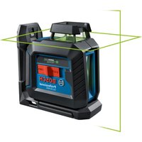
GLL100-40G Professional - Laser level BOSCH - Free user manual and instructions
Find the device manual for free GLL100-40G Professional BOSCH in PDF.

User questions about GLL100-40G Professional BOSCH
0 question about this device. Answer the ones you know or ask your own.
Ask a new question about this device
Download the instructions for your Laser level in PDF format for free! Find your manual GLL100-40G Professional - BOSCH and take your electronic device back in hand. On this page are published all the documents necessary for the use of your device. GLL100-40G Professional by BOSCH.
USER MANUAL GLL100-40G Professional BOSCH
IMPORTANT: IMPORTANT : IMPORTANTE: Read Before Using Lire avant usage Leer antes de usar

natural_image
Icon of a person reading a book inside a circle (no text or symbols)Operating/Safety Instructions Consignes de fonctionnement/sécurité Instrucciones de funcionamiento y seguridad
GLL100-40G

BOSCH
Call Toll Free for Consumer Information & Service Locations
natural_image
Diagram showing a 3D coordinate system with dashed lines and a labeled object (no text or symbols present)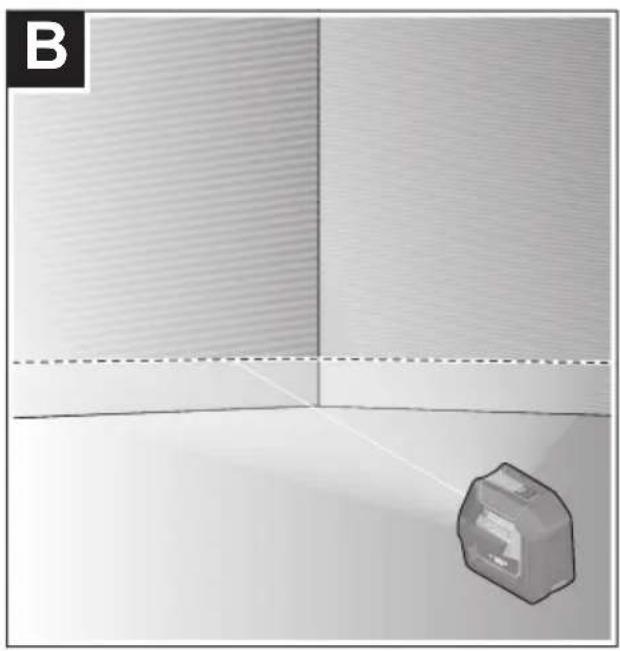
natural_image
Diagram showing a 3D object with a dashed line and a labeled section B, no readable text or symbols present.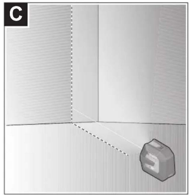
natural_image
3D diagram showing a cube with a dashed line and label 'C' (no text or symbols on the cube itself)
natural_image
3D diagram showing a camera mounted on a stand in a room with dashed lines indicating perspective projection (no text or symbols)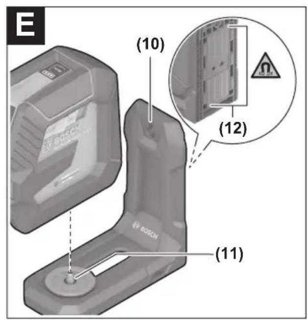

natural_image
3D mechanical component with mounting holes and a labeled section (13), no readable text or symbols present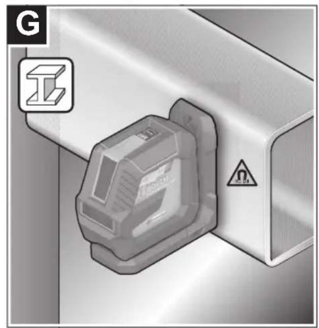
natural_image
3D architectural rendering of a room with walls, a camera on a tripod, and a wall-mounted monitor (no text or symbols)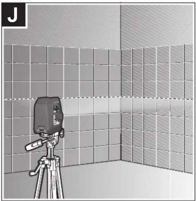
natural_image
Illustration of a camera on a tripod in a tiled room, no text or symbols present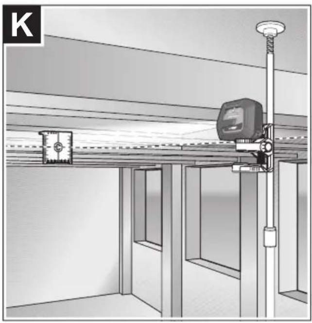
natural_image
Interior view of a room with ceiling-mounted equipment and a mounted device (no visible text or symbols)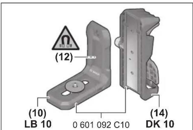
(17) BM 1 0601015A11
(18) RM 10 0601092A10
(20)
natural_image
Technical line drawing of a Bosch electric vehicle chassis (no text or symbols on body)(21) 2 610 053 598
Safety Symbols
The definitions below describe the level of severity for each signal word. Please read the manual and pay attention to these symbols.
 | This is the safety alert symbol. It is used to alert you to potential personal injury hazards. Obey all safety messages that follow this symbol to avoid possible injury or death. |
 | Read manual symbol - Alerts user to read manual. |
 | DANGER indicates a hazardous situation which, if not avoided, will result in death or serious injury. |
 | WARNING indicates a hazardous situation which, if not avoided, could result in death or serious injury. |
 | CAUTION indicates a hazardous situation which, if not avoided, could result in minor or moderate injury. |
General Safety Rules
WARNING Read all instructions. Failure to follow all instructions listed below may result in hazardous radiation exposure, electric shock, fire and/or serious injury. The term “tool” in all of the warnings listed below refers to your mains-operated (corded) tool or battery-operated (cordless) tool.
WARNING The following labels are on your laser tool for your convenience and safety. They indicate where the laser light is emitted by the tool. ALWAYS BE AWARE of their location when using the tool.
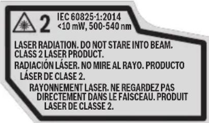

Do not direct the laser beam at persons or animals and do not stare into the laser beam yourself. This tool produces laser class 2 laser
radiation and complies with 21 CFR 1040.10 and 1040.11 except for deviations pursuant to Laser Notice No. 50, dated June 24, 2007. This can lead to persons being blinded.
DO NOT remove or deface any warning or caution labels. Removing labels increases the risk of exposure to laser radiation.
Use of controls or adjustments or performance of procedures other than those specified in this manual, may result in hazardous radiation exposure.
ALWAYS make sure that any bystanders in the vicinity of use are made aware of the dangers of looking directly into the laser tool.
DO NOT place the laser tool in a position that may cause anyone to stare into the laser beam intentionally or unintentionally. Serious eye injury could result.
ALWAYS position the laser tool securely. Damage to the laser tool and/or serious injury to the user could result if the laser tool fails.
ALWAYS use only the accessories that are recommended by the manufacturer of your laser tool. Use of accessories that have been designed for use with other laser tools could result in serious injury.
DO NOT use this laser tool for any purpose other than those outlined in this manual. This could result in serious injury.
DO NOT leave the laser tool "ON" unattended in any operating mode.
DO NOT disassemble the laser tool. There are no user serviceable parts inside. Do not modify the product in any way. Modifying the laser tool may result in hazardous laser radiation exposure.
DO NOT use the laser viewing glasses as safety goggles. The laser viewing glasses are used for improved visualization of the laser beam, but they do not protect against laser radiation.
DO NOT use the laser viewing glasses as sun glasses or in traffic. The laser viewing glasses do not afford complete UV protection and reduce color perception.
DO NOT use any optical tools such as, but not limited to, telescopes or transits to view the laser beam. Serious eye injury could result.
DO NOT stare directly at the laser beam or project the laser beam directly into the eyes of others. Serious eye injury could result.
Work area safety
Keep work area clean and well lit. Cluttered or dark areas invite accidents.
DO NOT operate the laser tool around children or allow children to operate the laser tool. Serious eye injury could result.
DO NOT use laser tools, attachments and accessories outdoors when lightning conditions are present.
Do not operate the measuring tool in explosive environments, such as in the presence of flammable liquids, gases or dusts.
Sparks can be created in the measuring tool which may ignite the dust or fumes.
Electrical safety
WARNING
Batteries can explode or leak, cause injury or fire.
To reduce this risk, always follow all instructions and warnings on the battery label and package.
DO NOT short any battery terminals.
DO NOT charge alkaline batteries.
DO NOT mix old and new batteries. Replace all of them at the same time with new batteries of the same brand and type.
DO NOT mix battery chemistries.
Dispose of or recycle batteries per local code.
DO NOT dispose of batteries in fire.
Keep batteries out of reach of children.
Remove batteries if the device will not be used for several months.
Personal safety
If laser radiation strikes your eye, you must deliberately close your eyes and immediately turn your head away from the beam.
Do not make any modifications to the laser equipment.
Stay alert, watch what you are doing and use common sense when operating a tool. Do not use a tool while you are tired or under the influence of drugs, alcohol or medication. A moment of inattention while operating a tool may result in serious personal injury or incorrect measurement results.
Use safety equipment. Always wear eye protection. Safety equipment such as dust mask, non-skid safety shoes, hard hat, or hearing protection used for appropriate conditions will reduce personal injuries.
Use caution when using laser tools in the vicinity of electrical hazards.
Magnets
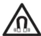
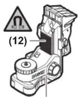
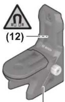
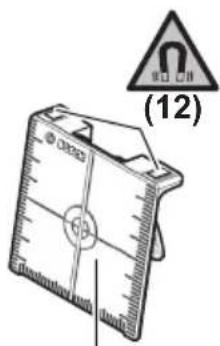
Keep the tool, mounting bracket LB 10 (10), position device BM 1 (17), rotation mount RM 10 (18), and laser target plate (20) away from implants or other medical devices such as pacemaker or insulin pumps. The magnets generate a field that can impair the function of implants or medical devices, which may lead to serious personal injury.
Keep the tool, mounting bracket LB 10 (10), position device BM 1 (17), rotation mount RM 10 (18), and laser target plate (20) away from magnetic data storage medium and magnetically sensitive equipment. The effect of the magnets can lead to irreversible data loss.
Use and care
Use the correct tool for your application. The correct tool will do the job better and safer.
Do not use the tool if the switch does not turn it on and off. Any tool that cannot be controlled with the switch is dangerous and must be repaired.
Store idle tool out of the reach of children and do not allow persons unfamiliar with the tool or these instructions to operate the tool. Tools are dangerous in the hands of untrained users.
Maintain tools. Check for misalignment or binding of moving parts, breakage of parts and any other condition that may affect the operation. If damaged, tool repaired before use. Many accidents are caused by poorly maintained tools.
Use the tool, accessories, etc., in accordance with these instructions and in the manner intended for the particular type of tool, taking into account the working conditions and the work to be performed. Use of the tool for operations different from those intended could result in a hazardous situation.
Service
Have your tool serviced by a qualified repair person using only identical replacement parts. This will ensure that the safety of the tool is maintained.
Develop a periodic maintenance schedule for tool. When cleaning a tool be careful not to disassemble any portion of the tool since internal wires may be misplaced or pinched or may be improperly mounted. Certain cleaning agents such as gasoline, carbon tetrachloride, ammonia, etc. may damage plastic parts.
SAVE THESE INSTRUCTIONS
Intended Use
The measuring tool is intended for determining and checking horizontal and vertical lines.
The measuring tool is suitable for indoor and outdoor use.
Features
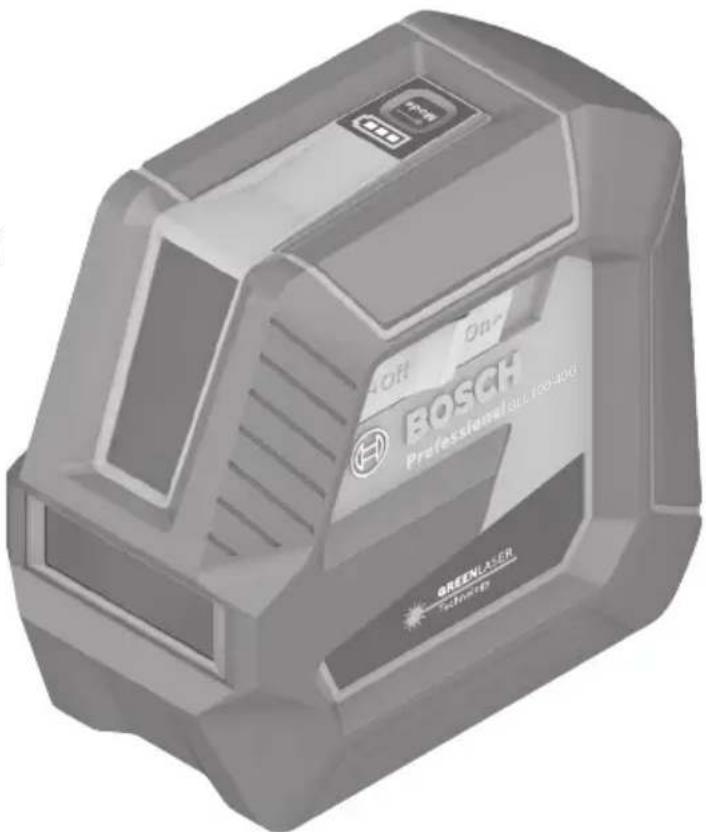
The numbering of the product features shown refers to the illustration of the tool on the graphic page.
1 Laser beam outlet window
2 Battery indicator
3 Button for laser operating mode
4 On/off switch
5 1/4" tripod mount
6 Battery compartment cover locking mechanism
7 Battery compartment cover
8 Laser warning label
9 Serial number
10 Magnetic mounting bracket (LB 10)
11 1/4" screw of the bracket
12 Magnet
13 Screw hole of the bracket
14 Ceiling clip (DK 10) ^
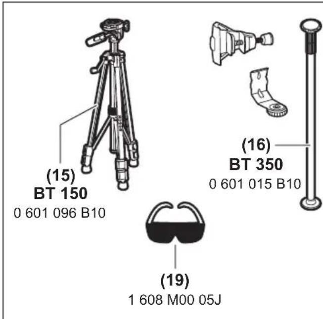
15 Tripod (BT 150) ^
16 Telescopic shaft (BT 350) ^
17 Universal positioning device (BM 1) ^
18 Rotating mount (RM 10) *
19 Laser enhancement glasses*
20 Laser target plate*
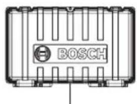
21 Hard Carrying Case
Technical Data
Model Number GLL100-40G
| Article number 3 601 K63 W10 | |
| Working range^A) | 100 ft (30 m) |
| Leveling accuracy^B)C) | ±1/8 in. at 30 ft (±3 mm at 10 m) |
| Self-leveling range (typical) ±4° | |
| Leveling duration (typical) <4s | |
| Operating temperature 14°F ~ 122 °F | (-10°C ~ +50 °C) |
| Storage temperature -4°F ~ 158 °F | (-20°C ~ +70 °C) |
| Max. altitude 6560 ft (2000 m) | |
| Relative air humidity, max. 90 % | |
| Pollution degree according IEC 61010D) | 2 |
| Laser class 2 | |
| Laser type 500-540 nm <10mW | |
| C_6 | 10 |
| Divergence 50 x 10 mrad (full angle) | |
| Tripod mount 1/4"-20 | |
| Batteries 4 x 1.5V LR6 (AA) | |
| Weight 1.26 lb (0.57 kg) | |
| Dimensions | |
| - Without LB 10 | 5" x 2.5" x 4.5" (126 x 63 x 115 mm) |
| - With LB 10 | 5.7" x 2.5" x 5.3" (145 x 63 x 134 mm) |
| Degree of protection^E) | IP 64 (dust tight and splash water protected) |
A) The working range may be reduced by unfavourable environmental conditions (e.g. direct sunlight).
B) At 20–25 °C
C) The values stated presuppose normal to favourable environmental conditions (e.g. no vibration, no fog, no smoke, no direct sunlight). Extreme fluctuations in temperature can cause deviations in accuracy.
D) Only non-conductive deposits occur, whereby occasional temporary conductivity caused by condensation is expected.
E) Excludes battery compartment.
The serial number (9) on the type plate is used to clearly identify your measuring tool.
Preparation
Inserting/Changing the batteries
It is recommended that you use alkaline manganese batteries to operate the measuring tool.
Press the locking mechanism (6) upwards to open the battery compartment cover (7) and remove the battery compartment cover. Insert the batteries.
When inserting the batteries, ensure that the polarity is correct according to the illustration on the inside of the battery compartment.
The battery indicator (2) always indicates the current status of the battery. If the batteries are running low, the laser lines will gradually become dimmer. If the
batteries are almost empty the battery indicator starts flashing continuously and the laser lines will blink every 5 min for 5 s until the tool turns off. If the batteries are empty, the laser lines and the battery indicator will flash once before the measuring tool switches off.
Always replace all the batteries at the same time. Only use batteries from the same manufacturer and which have the same capacity.
WARNING Take the batteries out of the measuring tool when you are not using it for a prolonged period of time. The batteries can corrode and self-discharge during prolonged storage in the measuring tool.
Operation
Starting Operation
WARNING direct sunlight.
Protect the measuring tool from moisture and
WARNING
Do not expose the measuring tool to any extreme temperatures or fluctuations in temperature. The precision of the measuring tool may be compromised if exposed to extreme temperatures or fluctuations in temperature. For example, do not leave it in a car for extended periods of time. If it has been subjected to significant fluctuations in temperature, first allow the measuring tool to adjust to the ambient temperature and then always carry out an accuracy check before continuing work (see “Leveling Accuracy”, page 12).
WARNING
Avoid substantial knocks to the
measuring tool and avoid dropping it. Always carry out an accuracy check before continuing work if the measuring tool has been subjected to severe external influences (see “Leveling Accuracy”, page 12).
WARNING Switch the measuring tool off when
transporting it. The pendulum unit is locked when the tool is switched off, as it can otherwise be damaged by extreme movements.
Switching On/Off
To switch on the measuring tool, slide the on/off switch (4) to the "On" position. As soon as it is switched on, the measuring tool emits laser beams from the laser beam outlet window (1).
⚠ WARNING Do not direct the laser beam at persons or animals and do not stare into the laser beam yourself (even from a distance).
To switch off the measuring tool, slide the on/off switch (4) to the Off position. The pendulum unit is locked when the tool is switched off.
WARNING Never leave the measuring tool unattended when switched on, and ensure the measuring tool is switched off after use. Others may be blinded by the laser beam.
If the maximum permitted operating temperature of 50 °C is exceeded, the tool shuts down to protect the laser diode. Once it has cooled down, the measuring tool is operational again and can be switched back on.
Automatic Shut-off
If no button on the measuring tool is pressed for approx. 120 min, the measuring tool will automatically switch itself off to preserve battery life.
To switch the measuring tool back on after it has been automatically switched off, you can either slide the on/off switch (4) to the "Off" position first and then switch the measuring tool back on, or press the laser operating mode button (3).
To deactivate the automatic shut-off function, hold down the laser mode button (3) for at least 3 s (with the measuring tool switched on). If the automatic shut-off function is deactivated, the laser beams will flash briefly as confirmation.
Note: If the operating temperature exceeds 45 °C, automatic shut-off can no longer be deactivated.
To activate the automatic shut-off function, switch the measuring tool off and on again.
Operating Modes
The measuring tool has three operating modes, which you can toggle through with the laser mode button (3):
- Cross-line mode (see figure A): Generates one horizontal and one vertical laser line
- Horizontal mode (see figure B): Generates one horizontal laser line
- Vertical mode (see figure C): Generates one vertical laser line
To change the operating mode, press the button for laser operating mode (3) as often as required until the laser beams are generated in the required operating mode.
All operating modes can be used with both automatic leveling and the incline function.
Automatic Leveling
The measuring tool monitors its position at all times during operation. It works with automatic leveling during set-up within the self-leveling range of ±4^ . Outside of the self-leveling range, it will automatically switch to the incline function.
Working with automatic leveling (see figures A–C)
Position the measuring tool on a level, firm surface or attach it to the magnetic mount bracket LB 10 (10) or the tripod (15).
The automatic leveling function automatically compensates irregularities within the self-leveling range of ±4^ . Once the laser beam is permanently lit, the measuring tool has levelled in.
If automatic leveling is not possible, e.g. because the surface on which the measuring tool stands deviates by more than 4^ from the horizontal plane, the laser lines will initially flash rapidly for 2 seconds, then flash rapidly every 5 seconds. The measuring tool is in the incline function.
In case of ground vibrations or position changes during operation, the measuring tool is automatically leveled again. Upon leveling, check the position of the laser beams with regard to the reference points to avoid errors arising from a change in the measuring tool's position.
Working with the Incline Function (see figure D)
Place the measuring tool on an inclined surface. When working with the incline function, the laser lines will initially flash rapidly for 2 seconds, then flash rapidly every 5 seconds.
In the incline function, the laser lines are no longer leveled and no longer necessarily run perpendicular to one another.
Leveling Accuracy
Influences on Accuracy
The ambient temperature has the greatest influence. Especially temperature differences occurring from the ground upward can refract the laser beam.
Since the largest difference in temperature layers is close to the ground, you should mount the measuring tool on a tripod and position it in the center of the work surface, wherever this is possible.
In addition to external influences, device-specific influences (e.g. falls or heavy impacts) can also lead to deviations. For this reason, check the leveling accuracy each time before beginning work.
First check the height accuracy and leveling accuracy of the horizontal laser line, then the leveling accuracy of the vertical laser line.
Should the measuring tool exceed the maximum deviation during one of the tests, please have it repaired by a Bosch after-sales service.
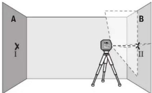
Checking the Height Accuracy of the Horizontal Line
For this check, you will need a free measuring distance of 16 ft (5 m) on firm ground between two walls (designated A and B).
- Mount the measuring tool close to wall A on a tripod, or place it on a firm, level surface. Switch on the measuring tool and select cross-line operation.
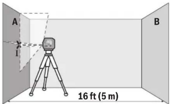
- Aim the laser at the closer wall A and allow the measuring tool to level in. Mark the middle of the point at which the laser lines cross on the wall (point I).
- Turn the measuring tool 180^ , allow it to level in and mark the point where the laser lines cross on the opposite wall B (point II). - Position the measuring tool - without rotating it - close to wall B, switch it on and allow it to level in.
- Align the height of the measuring tool (using the tripod or by placing objects underneath as required) so that the point where the laser lines cross exactly hits the previously marked point II on wall B.
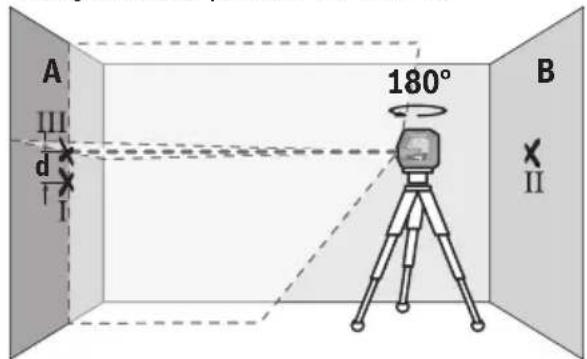
- Turn the measuring tool 180^ without adjusting the height. Aim it at wall A such that the vertical laser line runs through the already marked point I. Allow the measuring tool to level in and mark the point where the laser lines cross on wall A (point III).
- The discrepancy d between the two marked points I and III on wall A reveals the actual height deviation of the measuring tool.
The maximum permitted deviation on the measuring distance of 2 × 16 ft = 36 ft ( 2 × 5 m = 10 m) is as follows:
$$ \begin{array}{l} 3 2 \mathrm{ft} \times \pm 0. 0 0 3 6 \mathrm{in/ft} = \pm 1 / 8 \mathrm{in(0.115in)} \ (1 0 \mathrm{m} \times \pm 0. 3 \mathrm{mm/m} = \pm 3 \mathrm{mm}) \end{array} $$
The discrepancy d between points I and III must therefore amount to no more than 3 mm.
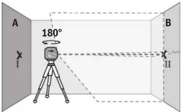
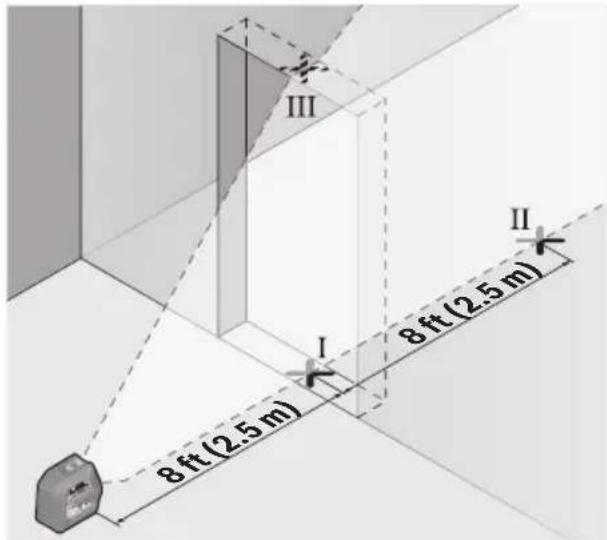
Checking the Leveling Accuracy of the Horizontal Line
For this check, you will need a free area of 16 × 16 ft ( 5 × 5 m).
- Mount the measuring tool in the middle between walls A and B on a tripod, or place it on a firm, level surface. Switch on the measuring tool and select horizontal operation. Allow the measuring tool to level in.
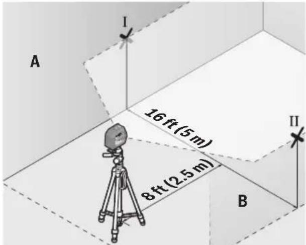
- At a distance of 8 ft (2.5 m) from the measuring tool, mark the center of the laser line on both walls (point I on wall A and point II on wall B).
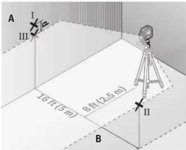
- Set up the measuring tool at a 16 ft (5 m) distance and rotated by 180^ and allow it to level in.
- Align the height of the measuring tool (using the tripod or by placing objects underneath as required) so that the center of the laser line exactly hits the previously marked point II on wall B.
- Mark the center of the laser line on wall A as point III (vertically above or below point I).
- The discrepancy d between the two marked points I and III on wall A reveals the actual horizontal deviation of the measuring tool.
The maximum permitted deviation on the measuring distance of 2 × 16 ft = 32 ft ( 2 × 5 m = 10 m) is as follows:
$$ \begin{array}{l} 3 2 \mathrm{ft} \times \pm 0. 0 0 3 6 \mathrm{in/ft} = \pm 1 / 8 \text { in(0.115in)} \ (1 0 \mathrm{m} \times \pm 0. 3 \mathrm{mm/m} = \pm 3 \mathrm{mm}) \end{array} $$
The discrepancy d between points I and III must therefore amount to no more than 3 mm.
Checking the Leveling Accuracy of the Vertical Line
For this check, you will need a door opening (on solid ground) which has at least 8 ft (2.5 m) of space either side of the door.
- Place the measuring tool 8 ft (2.5 m) away from the door opening on a firm, flat surface (not on a tripod). Switch on the measuring tool and select vertical operation. Aim the laser line at the door opening and allow the measuring tool to level in.
- Mark the center of the vertical laser line on the floor of the door opening (point I), 16 ft (5 m) away on the other side of the door opening (point II) and on the upper edge of the door opening (point III).
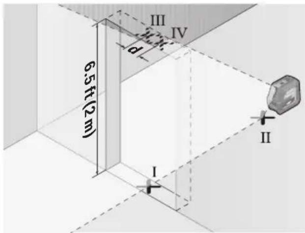
- Rotate the measuring tool 180^ and position it on the other side of the door opening, directly behind point II. Allow the measuring tool to level in and align the vertical laser line in such a way that its center passes through points I and II exactly.
-
Mark the center of the laser line on the upper edge of the door opening as point IV.
-
The discrepancy d between the two marked points III and IV reveals the actual vertical deviation of the measuring tool.
- Measure the height of the door opening.
You can calculate the maximum permitted deviation as follows:
Doubled height of the door opening × 0.0036 in/ft (0.3 mm/m)
Example: At a door opening height of 6.5 ft (2 m), the maximum deviation amounts to
$$ 2 \times 6. 5 \mathrm{ft} \times \pm 0. 0 0 3 6 \mathrm{in/ft} = 0. 0 4 7 \mathrm{in} $$
$$ (2 \times 2 \mathrm{m} \times \pm 0. 3 \mathrm{mm} / \mathrm{m} = \pm 1. 2 \mathrm{mm}) $$
The points III and IV must therefore be no further than 0.047 in (1.2 mm) from each other.
Working Advice
- Only the center of the laser line is used for marking. The width of the laser line changes depending on the distance.
Use with Attachments
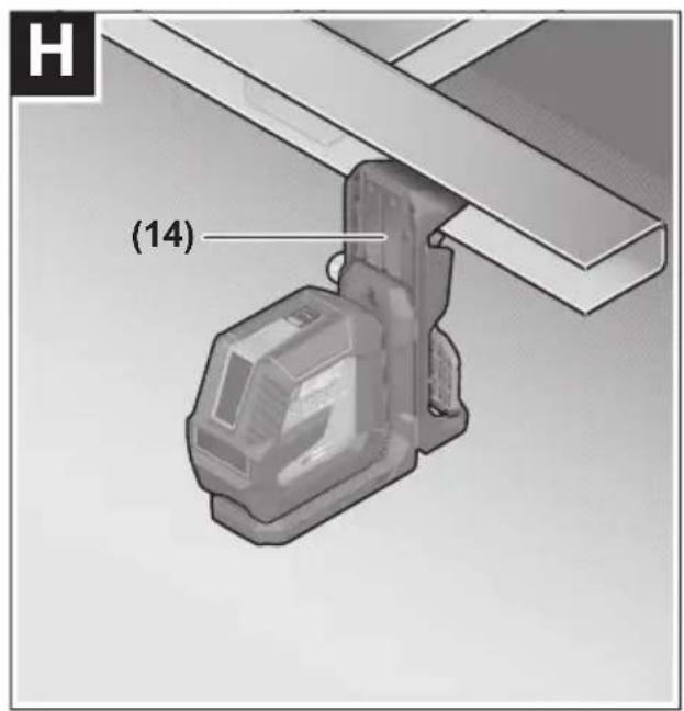
Working with the Magnetic Mounting Bracket LB 10 (see figures E-H)
You can secure the measuring tool on vertical surfaces or magnetisable materials using the magnetic mounting bracket (10). In conjunction with the ceiling clip (14), the measuring tool can also be aligned vertically.
Place the measuring tool with the 1/4" tripod mount (5) on the 1/4" screw (11) of the bracket and screw it tight.
Attachment options for the magnetic mounting bracket (10):
- Using a commercially available fastening screw, it can be attached via the screw hole (13) to drywall or wood (see figure F)
- Using the magnets (12), it can be attached to metallic surfaces (see figure G)
- Using the ceiling clip (14), it can be attached to crown mouldings (see figure H)
Roughly align the magnetic mounting bracket (10) before switching on the measuring tool.
Working with the Laser Target Plate
The laser target plate (20) improves visibility of the laser beam in unfavourable conditions and at greater distances.
The reflective half of the laser target plate (20) improves visibility of the laser line. The transparent half enables the laser line to be seen from behind the laser target plate.
Working with the Tripod (Accessory)
A tripod offers a stable, height-adjustable support surface for measuring. Place the measuring tool with the 1/4" tripod mount (5) on the thread of the tripod (15) or a conventional camera tripod. Tighten the measuring tool using the locking screw of the tripod.
Roughly align the tripod before switching on the measuring tool.
Securing with the universal Positioning Device BM 1 (accessory) (see figure K)
Using the universal positioning device (17), you can secure the measuring tool on vertical surfaces, pipes or magnetizable materials, for example. The universal positioning device is also suitable for use as a building tripod and facilitates height adjustment of the measuring tool.
Roughly align the universal holder (17) before switching on the measuring tool.
Working with the rotating mount RM 10 (accessory)
Using the rotating mount (18), you can rotate the measuring tool 360°. This enables you to set up the laser lines precisely, without having to change the position of the measuring tool.
You can use the rotating mount (18) as a floor stand or to attach the measuring tool to vertical surfaces; alternatively, the measuring tool can be attached to metallic surfaces by means of the magnets (12) or to crown mouldings in conjunction with the ceiling clip (14).
Roughly align the rotating mount (18) before switching on the measuring tool.
Laser Enhancement Glasses (Accessory)
The laser goggles filter out ambient light. This makes the light of the laser appear brighter to the eye.
- Do not use the laser glasses protective glasses.
The laser glasses make the laser beam easier to see; they do not protect you against laser radiation.
- Do not use the laser glasses sunglasses or while driving. The laser glasses do not provide full UV protection and impair your ability to see colours.
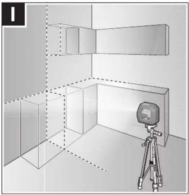
Example applications (see figures I–K)
Examples of possible applications for the measuring tool can be found on the graphics pages.
Maintenance and Service
Store and transport the tool only in the supplied protective case.
Keep the tool clean at all times.
Do not immerse the tool into water or other fluids.
Wipe off debris using a moist and soft cloth. Do not use any cleaning agents or solvents.
Regularly clean the surfaces at the exit opening of the laser in particular, and pay attention to any fluff of fibers.
If the tool should fail despite the care taken in manufacturing and testing procedures, repair should be carried out by an authorized after-sales service center for Bosch power tools.
In all correspondence and spare parts orders, please always include the 10-digit article number given on the type plate of the tool.
In case of repairs, send in the tool packed in its protective case (21).
ENVIRONMENT PROTECTION
Recycle raw materials & batteries instead of disposing of waste. The unit, accessories, packaging & used batteries should be sorted for environmentally friendly recycling in accordance with the latest regulations.

LIMITED WARRANTY OF BOSCH LASER AND MEASURINGTOOLPRODUCTS
Robert Bosch Tool Corporation (“Seller”) warrants to the original purchaser only, that all Bosch lasers and measuring tools will be free from defects in material or workmanship for a period of one (1) year from date of purchase. Bosch will extend warranty coverage to two (2) years when you register your product within eight (8) weeks after date of purchase. Product registration card must be complete and mailed to Bosch (postmarked within eight weeks after date of purchase), or you may register on-line at www.boschtools.com/Service/ProductRegistration. If you choose not to register your product, a one (1) year limited warranty will apply to your product.
30 Day Money Back Refund or Replacement -
If you are not completely satisfied with the performance of your laser and measuring tools, for any reason, you can return it to your Bosch dealer within 30 days of the date of purchase for a full refund or replacement. To obtain this 30-Day Refund or Replacement, your return must be accompanied by the original receipt for purchase of the laser or optical instrument product. A maximum of 2 returns per customer will be permitted.
SELLER'S SOLE OBLIGATION AND YOUR EXCLUSIVE REMEDY under this Limited Warranty and, to the extent permitted by law, any warranty or condition implied by law, shall be the repair or replacement of parts, without charge, which are defective in material or workmanship and which have not been misused, carelessly handled, or misrepaired by persons other than Seller or Authorized Service Center. To make a claim under this Limited Warranty, you must return the complete Bosch laser or measuring tool, transportation prepaid, to any BOSCH Factory Service Center or Authorized Service Center. Please include a dated proof of purchase with your tool. For locations of nearby service centers, please use our on-line service locator or call 1-877-267-2499.
THIS WARRANTY PROGRAM DOES NOT APPLY TO TRIPODS AND RODS. Robert Bosch Tool Corporation ("Seller") warrants tripods and leveling rods for a period of one (1) year from date of purchase.
THIS LIMITED WARRANTY DOES NOT APPLY TO OTHER ACCESSORY ITEMS AND RELATED ITEMS. THESE ITEMS RECEIVE A 90 DAY LIMITED WARRANTY.
To make a claim under this Limited Warranty, you must return the complete product, transportation prepaid. For details to make a claim under this Limited Warranty please visit www.boschtools.com or call 1-877-267-2499.
ANY IMPLIED WARRANTIES SHALL BE LIMITED IN DURATION TO ONE YEAR FROM DATE OF PURCHASE. SOME STATES IN THE U.S., AND SOME CANADIAN PROVINCES DO NOT ALLOW LIMITATIONS ON HOW LONG AN IMPLIED WARRANTY LASTS, SO THE ABOVE LIMITATION MAY NOT APPLY TO YOU.
IN NO EVENT SHALL SELLER BE LIABLE FOR ANY INCIDENTAL OR CONSEQUENTIAL DAMAGES (INCLUDING BUT NOT LIMITED TO LIABILITY FOR LOSS OF PROFITS) ARISING FROM THE SALE OR USE OF THIS PRODUCT. SOME STATES IN THE U.S., AND SOME CANADIAN PROVINCES DO NOT ALLOW THE EXCLUSION OR LIMITATION OF INCIDENTAL OR CONSEQUENTIAL DAMAGES, SO THE ABOVE LIMITATION MAY NOT APPLY TO YOU.
THIS LIMITED WARRANTY GIVES YOU SPECIFIC LEGAL RIGHTS, AND YOU MAY ALSO HAVE OTHER RIGHTS WHICH VARY FROM STATE TO STATE IN THE U.S., OR PROVINCE TO PROVINCE IN CANADA AND FROM COUNTRY TO COUNTRY.
THIS LIMITED WARRANTY APPLIES ONLY TO PRODUCTS SOLD WITHIN THE UNITED STATES OF AMERICA, CANADA AND THE COMMONWEALTH OF PUERTO RICO. FOR WARRANTY COVERAGE WITHIN OTHER COUNTRIES, CONTACT YOUR LOCAL BOSCH DEALER OR IMPORTER.
11 Vis 1/4 "du support
12 Aimants
13 Trou de vis du support
14 Clip de plafond (DK 10) *
15 Trépied compact (BT 150)*
© Robert Bosch Tool Corporation 1800 W. Central Road Mt. Prospect, IL 60056-2230
Exportado por: Robert Bosch Tool Corporation Mt. Prospect, IL 60056-2230, E.U.A.