
GLL 2-10 G Professional - Laser level BOSCH - Free user manual and instructions
Find the device manual for free GLL 2-10 G Professional BOSCH in PDF.


| Product type | Cross-line laser level |
| Brand | Bosch |
| Model | GLL 2-10 G Professional |
| Dimensions (L x W x H) | 124 x 64 x 100 mm |
| Weight | 0.38 kg (with batteries) |
| Power supply | 2 AA alkaline batteries 1.5 V |
| Typical battery life | 12 hours (with alkaline batteries) |
| Range | Up to 10 m (without receiver) |
| Laser class | 2 (EN 60825-1) |
| Wavelength | 635 nm, red |
| Accuracy | ± 0.5 mm/m |
| Functions | Horizontal and vertical lines, self-leveling, pendulum mode |
| Self-leveling range | ± 4° |
| Protection rating | IP54 (dust and splash protection) |
| Operating temperature | -10 °C to +45 °C |
| Storage temperature | -20 °C to +70 °C |
| Maintenance and cleaning | Clean with a soft, dry cloth. Do not use abrasive products. |
| Safety | Do not look directly into the laser beam. Use protective glasses if necessary. |
| Spare parts and repairability | Standard AA batteries. Repair by Bosch authorized service center. AC adapter available as option. |
| General information | Indoor and outdoor use (with receiver). 1/4" mounting bracket. |
Frequently Asked Questions - GLL 2-10 G Professional BOSCH
User questions about GLL 2-10 G Professional BOSCH
0 question about this device. Answer the ones you know or ask your own.
Ask a new question about this device
Download the instructions for your Laser level in PDF format for free! Find your manual GLL 2-10 G Professional - BOSCH and take your electronic device back in hand. On this page are published all the documents necessary for the use of your device. GLL 2-10 G Professional by BOSCH.
USER MANUAL GLL 2-10 G Professional BOSCH
GLL 2-10 G Professional
Robert Bosch Power Tools GmbH
70538 Stuttgart
GERMANY
www.bosch-pt.com
1609 92A 8EF (2023.01) T/198

1 609 92A 8EF

In Drilling Isolation,
Original instructions
(1) Laser Radiation. Do not stare into beam. Class 2 Consumer Laser Product EN506892021 IEC 60825-1:2014, < 10 mW, 500 - 540 nm


4






German
Safety instructions

www.bosch-pt.com/serviceaddresses
Disposal
All instructions must be read and observed in order for the measuring tool to function safely. The safeguards integrated into the measuring tool may be compromised if the
measuring tool is not used in accordance with these instructions. Never make warning signs on the measuring tool unrecognisable. SAVE THESE INSTRUCTIONS FOR FUTURE REFERENCE AND INCLUDE THEM WITH THE MEASURING TOOL WHEN TRANSFERRING IT TO A THIRD PARTY.
Warning! If operating or adjustment devices other than those specified here are used or other procedures are carried out, this can lead to dangerous exposure to radiation. The measuring tool is delivered with a laser warning sign (marked in the illustration of the measuring tool on the graphics page). If the text of the laser warning label is not in your national language, stick the provided warning label in your national language over it before operating for the first time.

Do not direct the laser beam at persons or animals and do not stare into the direct or reflected laser beam yourself. You could blind somebody, cause accidents or damage your eyes.
If laser radiation hits your eye, you must close your eyes and immediately turn your head away from the beam. Do not make any modifications to the laser equipment. Do not use the laser goggles (accessory) as protective goggles. The laser goggles make the laser beam easier to see; they do not protect you against laser radiation. Do not use the laser goggles (accessory) as sunglasses or while driving. The laser goggles do not provide full UV protection and impair your ability to see colours. Have the measuring tool serviced only by a qualified specialist using only original replacement parts. This will ensure that the safety of the measuring tool is maintained.
Do not let children use the laser measuring tool unsupervised. They could unintentionally blind themselves or other persons. Do not use the measuring tool in explosive atmospheres which contain flammable liquids, gases or dust. Sparks may be produced inside the measuring tool, which can ignite dust or fumes.

Keep the measuring tool and the magnetic accessories away from implants and other medical devices, e.g. pacemakers or insulin pumps. The magnets inside the measuring tool and accessories generate a field that can impair the function of implants and medical devices.
Keep the measuring tool and the magnetic accessories away from magnetic data storage media and magnetically sensitive devices. The effect of the magnets inside the measuring tool and accessories can lead to irreversible data loss.
Product Description and Specifications
Please observe the illustrations at the beginning of this operating manual.
Intended Use
The measuring tool is intended for determining and checking horizontal and vertical lines.
The measuring tool is suitable for indoor and outdoor use. This product is a consumer laser product in accordance with EN 50689.
Product Features
The numbering of the product features shown refers to the illustration of the measuring tool on the graphic page.
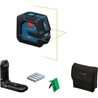
(1) Laser warning label (2) Laser beam outlet aperture (3) On/off switch (4) 5/8" tripod mount (5) 1/4" tripod mount (6) Vertical mode button (7) Horizontal mode button (8) Status indicator (9) Pendulum lock indicator (10) Serial number (11) Battery compartment cover (12) Battery compartment cover locking mechanism (13) Rotating mount (RM 1) a) (14) Guide rail 3) (15) Magnet a) (16) Fastening slot a) (17) Guide groove
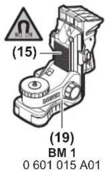
(18) Ceiling clip (BM 3) a) (19) Universal holder (BM 1) a) (20) Laser target plate 4 (21) Protective bag (22) Laser goggles a) (23) Tripod (BT 150) a) (24) Telescopic shaft (BT 350) a)
a) Accessories shown or described are not included with the product as standard. You can find the complete selection of accessories in our accessories range.
Technical Data
| Line laser GLL 2-10 G | |
| Article number | 3 601 K63 P.. |
| Working rangeA) | 10 m |
| Levelling accuracyB)(C) | ±0.3 mm/m |
| Self-levelling range ±4° | |
| Levelling time < 4 s | |
| Operating temperature -10 °C to +50 °C | |
| Storage temperature -20 °C to +70 °C | |
| Max. altitude 2000 m | |
| Relative air humidity max. 90 % | |
| Pollution degree according to IEC 61010-1 | 2D) |
| Laser class 2 | |
| Laser type 500-540 nm, < 10 mW | |
| C6 | 10 |
| Divergence 50 × 10 mrad (full angle) | |
| Tripod mount 1/4"; 5/8" | |
| Batteries 3 × 1.5 V LR6 (AA) | |
| Operating duration in operating modeB) | |
| - Cross-line mode 6 h | |
| - Line mode 12 h | |
| Weight according to EPTA-Procedure 01:2014 | 0.49 kg |
| Dimensions (length × width × height) | 112 × 55 × 106 mm |
| Protection rating | IP 54 (dust- and splash-proof) |
A) The working range may be reduced by unfavourable environmental conditions (e.g. direct sunlight). B) At 20-25°C C) The values stated presuppose normal to favourable environmental conditions (e.g. no vibration, no fog, no smoke, no direct sunlight). Extreme fluctuations in temperature can cause deviations in accuracy. D) Only non-conductive deposits occur, whereby occasional temporary conductivity caused by condensation is expected. The serial number (10) on the type plate is used to clearly identify your measuring tool.
Assembly
Inserting/changing the batteries
It is recommended that you use alkaline manganese batteries to operate the measuring tool.
To open the battery compartment cover (11), press on the locking mechanism (12) and remove the battery compartment cover. Insert the batteries.
When inserting the batteries, ensure that the polarity is correct according to the illustration on the inside of the battery compartment.
If the batteries are running low, the laser lines will gradually become dimmer.
If the batteries are almost empty, the status indicator (8) will flash green. The measuring tool can still be operated for approximately 1 hour after the first flash.
The laser lines will also flash for approximately five seconds every ten minutes.
If the batteries are empty, the laser lines will flash once before the measuring tool switches off.
Always replace all the batteries at the same time. Only use batteries from the same manufacturer and which have the same capacity.
▶ Take the batteries out of the measuring tool when you are not using it for a prolonged period of time. The batteries can corrode and self-discharge during prolonged storage in the measuring tool.
Working with the RM 1 rotating mount (see figures A–B)
Using the rotating mount (13), you can rotate the measuring tool 360°. This enables you to set up the laser lines precisely, without having to change the position of the measuring tool.
Place the measuring tool with the guide groove (17) on the guide rail (14) of the rotating mount (13) and slide the measuring tool all the way onto the platform.
To disconnect the measuring tool, pull it off the rotating mount in the opposite direction.
Rotating mount positioning options:
- Standing on a flat surface,
- Screwed to a vertical surface,
- On metallic ceiling strips using the ceiling clip (18),
- On metallic surfaces using the magnets (15).
▶ Keep your fingers away from the rear side of the magnetic accessory while attaching the accessory to surfaces. The strong pulling force of the magnets may jam your fingers.
Operation
Starting Operation
▶ Protect the measuring tool from moisture and direct sunlight.
Do not expose the measuring tool to extreme temperatures or fluctuations in temperature. For example, do not leave it in a car for extended periods of time. If it has been subjected to significant fluctuations in temperature, first allow the measuring tool to adjust to the ambient temperature and then always carry out an accuracy check before continuing work (see "Accuracy Check of the Measuring Tool", page 15). The precision of the measuring tool may be compromised if exposed to extreme temperatures or fluctuations in temperature. Avoid substantial knocks to the measuring tool and avoid dropping it. Always carry out an accuracy check before continuing work if the measuring tool has been subjected to severe external influences (see "Accuracy Check of the Measuring Tool", page 15). Switch the measuring tool off when transporting it. The pendulum unit is locked when the tool is switched off, as it can otherwise be damaged by big movements.
Switching On/Off
To switch on the measuring tool, slide the on/off switch (3) to the "On" position (for working with the pendulum lock)
or to the "On" position (for working with automatic leveling). The status indicator (8) lights up. As soon as it is switched on, the measuring tool emits laser lines from the outlet apertures (2).
Do not direct the laser beam at persons or animals and do not stare into the laser beam yourself (even from a distance).
To switch off the measuring tool, slide the on/off switch (3) to the "Off" position. The status indicator (8) goes out. The pendulum unit is locked when the tool is switched off.
Never leave the measuring tool unattended when switched on, and ensure the measuring tool is switched off after use. Others may be blinded by the laser beam.
If the maximum permitted operating temperature of 50°C is exceeded, the tool shuts down to protect the laser diode. Once it has cooled down, the measuring tool is operational again and can be switched back on.
Automatic shut-off
If no button on the measuring tool is pressed for approx.
120 min, the measuring tool will automatically switch itself off to preserve battery life.
To switch the measuring tool back on after it has been automatically switched off, you can either slide the on/off switch (3) to the "Off" position first and then switch the measuring tool back on, or press either the vertical mode button (6) or the horizontal mode button (7) once.
To deactivate automatic shut-off, hold down the horizontal mode button (7) for at least three seconds (with the measuring tool switched on). If automatic shut-off is deactivated, the laser lines will flash briefly as confirmation.
Note: If the operating temperature exceeds 45 °C, automatic shut-off can no longer be deactivated.
To activate the automatic shut-off function, switch the measuring tool off and on again.
Operating Modes
The measuring tool has several operating modes, which you can switch between at any time:
- Cross-line mode (see figure C): Generates one horizontal and one vertical laser line.
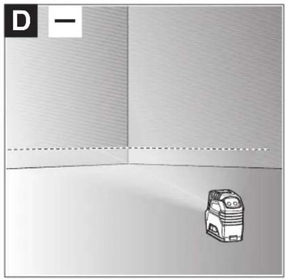
- Horizontal mode (see figure D): Generates one horizontal laser line.
- Vertical mode (see figure E): Generates one vertical laser line.
After switching on, the measuring tool is in cross-line operating mode. Using the buttons for horizontal mode (7) and vertical mode (6), you can switch the horizontal and vertical laser lines on and off independently of one another.
All operating modes can be selected with both automatic levelling or the pendulum lock.
Automatic Levelling
Working with automatic levelling
Position the measuring tool on a level, firm surface or attach it to the rotating mount (13) or the tripod (23).
For work with automatic levelling, slide the on/off switch (3) to the "on" position.
The automatic levelling function automatically compensates irregularities within the self-levelling range of ±4°. The levelling is finished as soon as the laser lines stop moving.
If automatic levelling is not possible, e.g. because the surface on which the measuring tool stands deviates by more than 4° from the horizontal plane, the laser beams will flash quickly.
If this is the case, set up the measuring tool in a level position and wait for the self-levelling to take place. As soon as the measuring tool is within the self-levelling range of ±4°, the laser beams will light up continuously.
In case of ground vibrations or position changes during operation, the measuring tool is automatically levelled again.
Upon levelling, check the position of the laser beams with regard to the reference points to avoid errors arising from a change in the measuring tool's position.
Working with the pendulum lock
For work with the pendulum lock, slide the on/off switch (3) to the "on" position. The pendulum lock indicator (9)
lights up red and the laser lines continuously flash slowly. For work with the pendulum lock, automatic levelling is switched off. You can hold the measuring tool freely in your hand or place it on a sloping surface. This means that the laser beams are no longer levelled and no longer necessarily run perpendicular to one another.
Accuracy Check of the Measuring Tool
Influences on Accuracy
The largest influence is exerted by the ambient temperature. In particular, temperature differences that occur from the ground upwards can refract the laser beam.
In order to minimise thermal influences resulting from heat rising from the floor, it is recommended that you use the measuring tool on a tripod. In addition, position the measuring tool in the centre of the work surface, wherever this is possible.
In addition to external influences, device-specific influences (e.g. falls or heavy impacts) can also lead to deviations. For this reason, check the levelling accuracy each time before beginning work.
First check the height accuracy and levelling accuracy of the horizontal laser line, then the levelling accuracy of the vertical laser line.
Should the measuring tool exceed the maximum deviation during one of the tests, please have it repaired by a Bosch after-sales service.
Checking the Height Accuracy of the Horizontal Line
For this check, you will need a free measuring distance of 5 m on firm ground between two walls (designated A and B).
- Mount the measuring tool close to wall A on the holder or a tripod, or place it on a firm, level surface. Switch on the measuring tool with the automatic levelling function enabled and select cross-line mode.

- Aim the laser at the closer wall A and allow the measuring tool to level in. Mark the middle of the point at which the laser lines cross on the wall (point I).

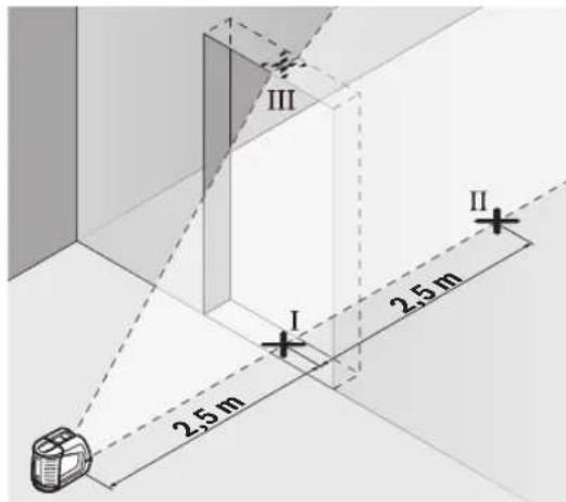
- Turn the measuring tool 180°, allow it to level in and mark the point where the laser lines cross on the opposite wall B (point II).
- Position the measuring tool – without rotating it – close to wall B, switch it on and allow it to level in.

- Align the height of the measuring tool (using the tripod or by placing objects underneath as required) so that the point where the laser lines cross exactly hits the previously marked point II on wall B.

- Turn the measuring tool 180° without adjusting the height. Aim it at wall A such that the vertical laser line runs through the already marked point I. Allow the measuring tool to level in and mark the point where the laser lines cross on wall A (point III).
- The discrepancy d between the two marked points I and III on wall A reveals the actual height deviation of the measuring tool.
The maximum permitted deviation on the measuring distance of 2 × 5 m = 10 m is as follows:
10 m × ±0.3 mm/m = ±3 mm. The discrepancy d between points I and III must therefore amount to no more than 3 mm.
Checking the Level Accuracy of the Horizontal Line
For this check, you will need a free area of 5 × 5 m.
- Mount the measuring tool in the middle between walls A and B on the holder or a tripod, or place it on a firm, flat surface. Switch on the measuring tool with the automatic levelling function enabled and select horizontal mode. Allow the measuring tool to level in.

- At a distance of 2.5 m from the measuring tool, mark the centre of the laser line on both walls (point I on wall A and point II on wall B).

- Set up the measuring tool at a 5 m distance and rotated by 180° and allow it to level in.
- Align the height of the measuring tool (using the tripod or by placing objects underneath as required) so that the centre of the laser line exactly hits the previously marked point II on wall B.
- Mark the centre of the laser line on wall A as point III (vertically above or below point I).
- The discrepancy d between the two marked points I and III on wall A reveals the actual horizontal deviation of the measuring tool.
The maximum permitted deviation on the measuring distance of 2 × 5 m = 10 m is as follows:
10 m × ±0.3 mm/m = ±3 mm. The discrepancy d between points I and III must therefore amount to no more than 3 mm.
Checking the Level Accuracy of the Vertical Line
For this check, you will need a door opening (on solid ground) which has at least 2.5 m of space either side of the door.
- Place the measuring tool 2.5 m away from the door opening on a firm, flat surface (not on a tripod). Switch on the measuring tool in the mode with automatic levelling. Select vertical mode and allow the measuring tool to level in.

- Mark the centre of the vertical laser line on the floor of the door opening (point I), 5 m away on the other side of the door opening (point II) and on the upper edge of the door opening (point III).
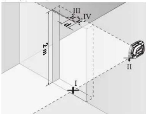
- Set up the measuring tool on the other side of the door opening, directly behind point II. Allow the measuring tool to level in and align the vertical laser line in such a way that its centre passes through points I and II exactly.
- Mark the centre of the laser line on the upper edge of the door opening as point IV.
- The discrepancy d between the two marked points III and IV reveals the actual vertical deviation of the measuring tool.
- Measure the height of the door opening.
You can calculate the maximum permitted deviation as follows:
Doubled height of the door opening × 0.3 mm/m
Example: At a door opening height of 2 m, the maximum deviation amounts to
2 × 2 m × ±0.3 mm/m = ±1.2 mm. The points III and IV must therefore be no further than 1.2 mm from each other.
Working Advice
▶ Only the centre of the laser line must be used for marking. The width of the laser line changes depending on the distance.
Working with the Laser Target Plate
The laser target plate (20) improves visibility of the laser beam in unfavourable conditions and at greater distances. The reflective surface of the laser target plate (20) improves visibility of the laser line. The transparent surface enables the laser line to be seen from behind the laser target plate.
Working with the Tripod (Accessory)
A tripod offers a stable, height-adjustable support surface for measuring. Place the measuring tool with the 1/4" tripod mount (5) on the thread of the tripod (23) or a conventional camera tripod. Use the 5/8" tripod mount (4) to secure the measuring tool on a conventional building tripod. Tighten the measuring tool using the locking screw of the tripod.
Roughly align the tripod before switching on the measuring tool.
Securing with the universal holder (accessory) (see figure F)
You can secure the measuring tool, for example, on vertical surfaces or magnetisable materials using the universal holder (19). The universal holder is also suitable for use as a floor stand and facilitates the height adjustment of the measuring tool.
▶ Keep your fingers away from the rear side of the magnetic accessory while attaching the accessory to surfaces. The strong pulling force of the magnets may jam your fingers.
Roughly align the universal holder (19) before switching on the measuring tool.
Laser Goggles (Accessory)
The laser goggles filter out ambient light. This makes the light of the laser appear brighter to the eye.
▶ Do not use the laser goggles (accessory) as protective goggles. The laser goggles make the laser beam easier to see; they do not protect you against laser radiation. ▶ Do not use the laser goggles (accessory) as sunglasses or while driving. The laser goggles do not provide full UV protection and impair your ability to see colours.
Example applications (see figures F-H)
Examples of possible applications for the measuring tool can be found on the graphics pages.
Maintenance and Service
Maintenance and Cleaning
Keep the measuring tool clean at all times.
Never immerse the measuring tool in water or other liquids. Wipe off any dirt using a damp, soft cloth. Do not use any detergents or solvents.
The areas around the outlet aperture of the laser in particular should be cleaned on a regular basis. Make sure to check for lint when doing this.
Only store and transport the measuring tool in the protective pouch (21).
If the measuring tool needs to be repaired, send it off in the protective pouch (21).
After-Sales Service and Application Service
Our after-sales service responds to your questions concerning maintenance and repair of your product as well as spare parts. You can find explosion drawings and information on spare parts at: www.bosch-pt.com
The Bosch product use advice team will be happy to help you with any questions about our products and their accessories.
In all correspondence and spare parts orders, please always include the 10-digit article number given on the nameplate of the product.
Great Britain
Robert Bosch Ltd. (B.S.C.)
P.O. Box 98
Broadwater Park
North Orbital Road
Denham Uxbridge
UB9 5HJ
At www.bosch-pt.co.uk you can order spare parts or arrange the collection of a product in need of servicing or repair.
Tel. Service: (0344) 7360109
E-Mail: boschservicecentre@bosch.com
You can find further service addresses at:
www.bosch-pt.com/serviceaddresses
Disposal
Measuring tools, accessories and packaging should be recycled in an environmentally friendly manner.

Do not dispose of measuring tools or batteries with household waste.
Only for EU countries:
According to the Directive 2012/19/EU on waste electrical and electronic equipment and its transposition into national law, measuring tools that are no longer usable, and, according to the Directive 2006/66/EC, defective or drained batteries must be collected separately and disposed of in an environmentally correct manner.
If disposed incorrectly, waste electrical and electronic equipment may have harmful effects on the environment and human health, due to the potential presence of hazardous substances.
Only for United Kingdom:
According to The Waste Electrical and Electronic Equipment Regulations 2013 (SI 2013/3113) (as amended) and the Waste Batteries and Accumulators Regulations 2009 (SI 2009/890) (as amended), products that are no longer usable must be collected separately and disposed of in an environmentally friendly manner.
French
Robert Bosch (France) S.A.S.
www.bosch-pt.com/serviceaddresses
www.bosch-pt.com/serviceaddresses
Disposal
www.bosch-pt.com/serviceaddresses
Disposal
www.bosch-pt.com/serviceaddresses
Disposal
Bosch Service Center
Telegrafvej 3
2750 Ballerup
Spare parts can be ordered online or a repair order can be created at www.bosch-pt.dk.
Service Center phone: 44898855
Fax: 44898755
E-mail: vaerktoej@dk.bosch.com
www.bosch-pt.com/serviceaddresses
56 | Swedish
Disposal
Bosch Service Center
Telegrafvej 3
2750 Ballerup
Denmark
Tel.: (08) 7501820 (within Sweden)
Fax: (011) 187691
www.bosch-pt.com/serviceaddresses
Waste management
www.bosch-pt.com/serviceaddresses
Disposal
www.bosch-pt.com/serviceaddresses
Disposal
www.bosch-pt.com/serviceaddresses
Disposal
www.bosch-pt.com/serviceaddresses
Disposal
Robert Bosch Sp. z o.o.
www.bosch-pt.com/serviceaddresses
Waste disposal
Bosch Service Center PT
K Vápence 1621/16
692 01 Mikulov
www.bosch-pt.com/serviceaddresses
Disposal
www.bosch-pt.com/serviceaddresses
Disposal
www.bosch-pt.com/serviceaddresses
Waste disposal
www.bosch-pt.com/serviceaddresses
Disposal
www.bosch-pt.com/serviceaddresses
Disposal
www.bosch-pt.com/serviceaddresses
Disposal
Power tool service
Strada Horia Măcelariu Nr. 30–34, sector 1
013937 Bucharest
www.bosch-pt.com/serviceaddresses
Disposal
Power tool service
Horia Măcelariu Street No. 30–34, Sector 1
013937 Bucharest, Romania
www.bosch-pt.com/bg/bg/
www.bosch-pt.com/serviceaddresses
Disposal
www.bosch-pt.com/serviceaddresses
Disposal
- Aim the laser at the nearby wall A and allow the measuring tool to level itself. Mark the center of the point where the laser lines cross on the wall (point I).

- Turn the measuring tool by 180°, allow it to level, and mark the crossing point of the laser lines on the opposite wall B (point II).
- Place the measuring tool – without turning it – near wall B, switch it on, and allow it to level.

- Align the measuring tool in height (using the tripod or by placing shims as necessary) so that the crossing point of the laser lines exactly hits the previously marked point II on wall B.

- Turn the measuring tool by 180° without changing its height. Aim it at wall A so that the vertical laser line passes through the already marked point I. Allow the measuring tool to level and mark the crossing point of the laser lines on wall A (point III).
- The difference d between the two marked points I and III on wall A represents the actual height deviation of the measuring tool.
On a measuring section of 2 × 5 m = 10 m, the maximum permissible deviation is:
10 m × ±0.3 mm/m = ±3 mm. The difference d between points I and III may be at most 3 mm.
Checking the leveling accuracy of the horizontal line
For this check, a free area of approximately 5 × 5 m is required.
- Mount the measuring tool in the middle between walls A and B on the holder or tripod, or place it on a firm, flat surface. Switch on the measuring tool in mode with automatic leveling and select horizontal mode. Wait until the measuring tool has leveled.

- Mark the center of the laser line on both walls at a distance of 2.5 m from the measuring tool (point I on wall A and point II on wall B).

- Set up the measuring tool rotated by 180° at a distance of 5 m and allow it to level.
- Align the measuring tool in height (using the tripod or by placing objects underneath as required) so that the center of the laser line exactly hits the previously marked point II on wall B.
- Mark the center of the laser line on wall A as point III (vertically above or below point I).
- The difference d between the two marked points I and III on wall A indicates the actual deviation of the measuring tool from the horizontal.
On a measuring section of 2 × 5 m = 10 m, the maximum permissible deviation is:
10 m × ±0.3 mm/m = ±3 mm. The difference d between points I and III may therefore be at most 3 mm.
Checking the leveling accuracy of the vertical line
For this check, you need a door opening with at least 2.5 m of space on each side of the door (on firm ground).
- Place the measuring tool at a distance of 2.5 m from the door opening on a firm, flat surface (not on a tripod). Switch on the measuring tool in mode with automatic leveling. Select vertical mode and allow the measuring tool to level.
- Mark the center of the vertical laser line on the floor of the door opening (point I), at a distance of 5 m from the other side of the door opening (point II), and on the upper edge of the door opening (point III).

www.bosch-pt.com/serviceaddresses
Disposal
Measuring tools, accessories, and packaging should be recycled in an environmentally friendly manner.

Do not dispose of measuring tools and batteries in household waste!
Only for EU countries:
According to the European Directive 2012/19/EU on waste electrical and electronic equipment and its implementation in national law, measuring tools that can no longer be used, and according to the European Directive 2006/66/EC, defective or exhausted batteries/accumulators must be collected separately and recycled in an environmentally friendly manner.
- At a distance of 2.5 m from the measuring tool, mark the center of the laser line on both walls (point I on wall A and point II on wall B).

- At a distance of 2.5 m from the measuring tool, mark the center of the laser line on both walls (point I on wall A and point II on wall B).

- Rotate the measuring tool 180° at a distance of 5 m and level it.
- Align the measuring tool in height (using the tripod or by placing shims as needed) so that the center of the laser line exactly hits the previously marked point II on wall B.
- On wall A, mark the center of the laser line as point III (vertically above or below point I).
- The difference d between the two marked points I and III on wall A gives the actual deviation of the measuring tool from horizontal.
- Mark the center of the vertical laser line at the bottom of the door opening (point I), at a distance of 5 m on the other side of the door opening (point II), and on the upper edge of the door opening (point III).

www.bosch-pt.com/serviceaddresses
Disposal
Measuring tools, accessories, and packaging should be brought to environmentally friendly recycling.

Do not dispose of measuring tools and batteries in household waste!
For EU countries only:
In accordance with the European Directive 2012/19/EU on waste electrical and electronic equipment and its implementation in national law, unusable measuring tools, and in accordance with the European Directive 2006/66/EC, defective or exhausted batteries/accumulators must be collected separately and brought to environmentally friendly recycling.
www.bosch-pt.com/serviceaddresses
Waste management
www.bosch-pt.com/serviceaddresses
www.bosch-pt.com/serviceaddresses
Disposal
Robert Bosch Morocco SARL
- شارع الملازم محمد م我和ود
20300 الدار البيضاء
www.bosch-pt.com/serviceaddresses
Turn back 180°
www.bosch-pt.com/serviceaddresses

- GLL 2-10 G PROFESSIONAL
- GERMAN
- SAFETY INSTRUCTIONS
- DISPOSAL
- PRODUCT DESCRIPTION AND SPECIFICATIONS
- INTENDED USE
- PRODUCT FEATURES
- ASSEMBLY
- INSERTING/CHANGING THE BATTERIES
- WORKING WITH THE RM 1 ROTATING MOUNT (SEE FIGURES A–B)
- OPERATION
- STARTING OPERATION
- SWITCHING ON/OFF
- AUTOMATIC SHUT-OFF
- OPERATING MODES
- AUTOMATIC LEVELLING
- WORKING WITH AUTOMATIC LEVELLING
- WORKING WITH THE PENDULUM LOCK
- ACCURACY CHECK OF THE MEASURING TOOL
- INFLUENCES ON ACCURACY
- CHECKING THE HEIGHT ACCURACY OF THE HORIZONTAL LINE
- CHECKING THE LEVEL ACCURACY OF THE HORIZONTAL LINE
- CHECKING THE LEVEL ACCURACY OF THE VERTICAL LINE
- WORKING ADVICE
- WORKING WITH THE LASER TARGET PLATE
- WORKING WITH THE TRIPOD (ACCESSORY)
- SECURING WITH THE UNIVERSAL HOLDER (ACCESSORY) (SEE FIGURE F)
- LASER GOGGLES (ACCESSORY)
- EXAMPLE APPLICATIONS (SEE FIGURES F-H)
- MAINTENANCE AND SERVICE
- MAINTENANCE AND CLEANING
- AFTER-SALES SERVICE AND APPLICATION SERVICE
- GREAT BRITAIN
- YOU CAN FIND FURTHER SERVICE ADDRESSES AT
- ONLY FOR EU COUNTRIES
- ONLY FOR UNITED KINGDOM
- FRENCH
- SWEDISH
- WASTE MANAGEMENT
- WASTE DISPOSAL
- CHECKING THE LEVELING ACCURACY OF THE HORIZONTAL LINE
- CHECKING THE LEVELING ACCURACY OF THE VERTICAL LINE
- FOR EU COUNTRIES ONLY
Brand : BOSCH
Model : GLL 2-10 G Professional
Category : Laser level