USER MANUAL GRL 250 HV Professional BOSCH
no Original electric properties
A. AEGISTEROPIE
el Tntrurco ooeey
rOriginal iselng Lalima
pl Instukcia Cryinalna
es Povodni nevod k pouzivani
sk Povodny navod na pouzilit
hu Eredeli hasznalati ulasitas
POpHmHaIbHe pyKOBgCTo No
KcHryaT
UK OgnHnHaNb HcTpyCJ3
ecryyataa
kkTnndnayECKAYDfHsH
TYNNCKAC
ro Instruction or
bgOpwnnnaHnHcTpykua
mkOpHHHNOyNarCBOaDabota
sr Originalno uputivo za rad
slIzyimana navodila
hr Originalne upute za rad
YkpaHcbKa ..CtoPiHa 199
Kaak. 5er 210
MaKeDoHcN. CtpaHua 244
Srpski Strana 255
Slovenscina Stran 265
www.bosch-pt.com/serviceaddresses
Entsorgung

Safety Instructions for Rotary Lasers and Remote Control

All instructions must be read and observed in order to enable work to be carried out safely. The integrated safeguards may be compromised if these instructions are not
observed. Never make warning signs unrecognisable. STORE THESE INSTRUCTIONS IN A SAFE PLACE AND INCLUDE THEM WITH THE PRODUCT WHEN GIVING IT TO A THIRD PARTY.
Warning! If operating or adjustment devices other than those specified here are used or other procedures are carried out, this can lead to dangerous exposure to radiation.
The measuring tool is delivered with a laser warning sign (marked in the illustration of the measuring tool on the graphics page).
If the text of the laser warning label is not in your national language, stick the provided warning label in your national language over it before operating for the first time.
Do not make any modifications to the laser equipment.
Do not use the laser goggles (accessory) as protective goggles. The laser goggles make the laser beam easier to see; they do not protect you against laser radiation.
Do not use the laser goggles (accessory) as sunglasses or while driving. The laser goggles do not provide full UV protection and impair your ability to see colours.
Have your product serviced only by a qualified specialist using only original replacement parts. This will ensure that the safety of the product is maintained.
Do not let children use the laser measuring tool unsupervised. They could accidentally dazzle someone.
Do not operate in potentially explosive atmospheres, such as in the presence of flammable liquids, gases or dusts. Sparks may be produced, which can ignite dust or fumes.
Additional Safety Instructions for GRL 250 HV :

Do not direct the laser beam at persons or animals and do not stare into the direct or reflected laser beam yourself. You could blind somebody, cause accidents or damage your eyes.
If laser radiation hits your eye, you must close your eyes and immediately turn your head away from the beam.
Additional Safety Instructions for GRL 300 HV, GRL 300 HVG:
20|English
The laser exit holes on the measuring tool are marked with warning labels. Take note of their position when using the measuring tool.
If the text of these labels is not in your national language, stick the provided warning label in your national language over it before operating for the first time.
Comply with any applicable national regulations when using a laser from laser class 3R. Failure to comply with these regulations may cause injuries.
The measuring tool should only be operated by people who have experience in using laser tools. According to EN 60825-1, this includes knowledge of the biological impact of the laser on eyes and skin as well as the correct application of laser safety guidelines to prevent hazards.
Mark out the area where the measuring tool is being used with suitable laser warning signs. This will prevent people who are not using the measuring tool from entering the danger zone.
Do not store the measuring tool in places which can be accessed by unauthorised individuals. People who are unfamiliar with the operation of the measuring tool may cause harm to themselves or others.

Do not direct the laser beam at persons or animals and do not stare into the laser beam yourself. This measuring tool generates laser class 3R laser radiation according to EN 60825-1. Looking into the laser beam directly can cause eye injuries - even from far away.
Ensure that the laser radiation area is guarded or screened. Restricting the laser radiation to controlled areas prevents eye injuries being caused to people who are not using the laser measuring tool.
Always position the measuring tool such that the laser beams travel far above or below eye level. This ensures that no eye injuries are caused.
- Avoid laser beam reflections on smooth surfaces such as windows or mirrors. Even the reflected laser beam can cause eye injuries.
Additional Safety Instructions
Do not use any optical instruments such as binoculars or magnifying glasses to view the radiation source. Doing so can damage your eyes.
Keep the magnetic accessories away from implants and other medical devices, e.g. pacemakers or insulin pumps. The magnets in the accessories generate a field that can impair the function of implants and medical devices.
- Keep the magnetic accessories away from magnetic data storage media and magnetically-sensitive devices. The effect of the magnets in the accessories can lead to irreversible data loss.
Do not open the rechargeable batteries or batteries. There is a risk of short-circuiting.
In case of damage and improper use of the battery, vapours may be emitted. The battery can set alight or explode. Ensure the area is well ventilated and seek medical attention should you experience any adverse effects. The vapours may irritate the respiratory system.
If used incorrectly or if the battery is damaged, flammable liquid may be ejected from the battery. Contact with this liquid should be avoided. If contact accidentally occurs, rinse off with water. If the liquid comes into contact with your eyes, seek additional medical attention. Liquid ejected from the battery may cause irritation or burns.
The battery can be damaged by pointed objects such as nails or screwdrivers or by force applied externally. An internal short circuit may occur, causing the battery to burn, smoke, explode or overheat.
- When the battery is not in use, keep it away from paper clips, coins, keys, nails, screws or other small metal objects that could make a connection from one terminal to another. A short circuit between the battery terminals may cause burns or a fire.
Only use the Bosch rechargeable battery with products from the manufacturer. This is the only way in which you can protect the battery against dangerous overload.
Only charge the Bosch rechargeable battery with the charger it is supplied with.

Protect the rechargeable batteries against heat, e.g. against continuous sunlight, fire, dirt, water, and moisture. There is a risk of explosion and short circuit.
Safety instructions for chargers

Read all the safety information and instructions. Failure to observe the safety information and follow instructions may result in electric shock, fire and/or serious injury.
Save all warnings and instructions for future reference.
This charger is not intended for use by children or persons with physical, sensory or mental limitations or a lack of experience or knowledge. This charger can be used by children aged 8 or older and by persons who have physical, sensory or mental limitations or a lack of experience or knowledge if a person responsible for their
safety supervises them or has instructed them in the safe operation of the charger and they understand the associated dangers. Otherwise, there is a risk of operating errors and injuries.
Supervise children during use, cleaning and maintenance. This will ensure that children do not play with the charger.
Only charge Bosch NiCd/NiMH rechargeable batteries with a capacity of 9 Ah or more (2 battery cells). The battery voltage must match the battery charging voltage of the charger. Do not charge any non-rechargeable batteries. Otherwise there is a risk of fire and explosion.

Do not expose the charger to rain or wet condi
tions. Water entering a power tool will increase the risk of electric shock.
Charge the measuring tool only with the supplied charger.
- Keep the charger clean. Dirt poses a risk of electric shock.
Always check the charger, cable and plug before use. Stop using the charger if you discover any damage. Do not open the charger yourself, and have it repaired only by a qualified specialist using only original replacement parts. Damaged chargers, cables and plugs increase the risk of electric shock.
Do not operate the charger on an easily ignited surface (e.g. paper, textiles, etc.) or in a flammable environment. There is a risk of fire due to the charger heating up during operation.
Products sold in GB only:
Your product is fitted with an BS 1363/A approved electric plug with internal fuse (ASTA approved to BS 1362).
If the plug is not suitable for your socket outlets, it should be cut off and an appropriate plug fitted in its place by an authorised customer service agent. The replacement plug should have the same fuse rating as the original plug.
The severed plug must be disposed of to avoid a possible shock hazard and should never be inserted into a mains socket elsewhere.
Product Description and Specifications
Please observe the illustrations at the beginning of this operating manual.
Intended Use
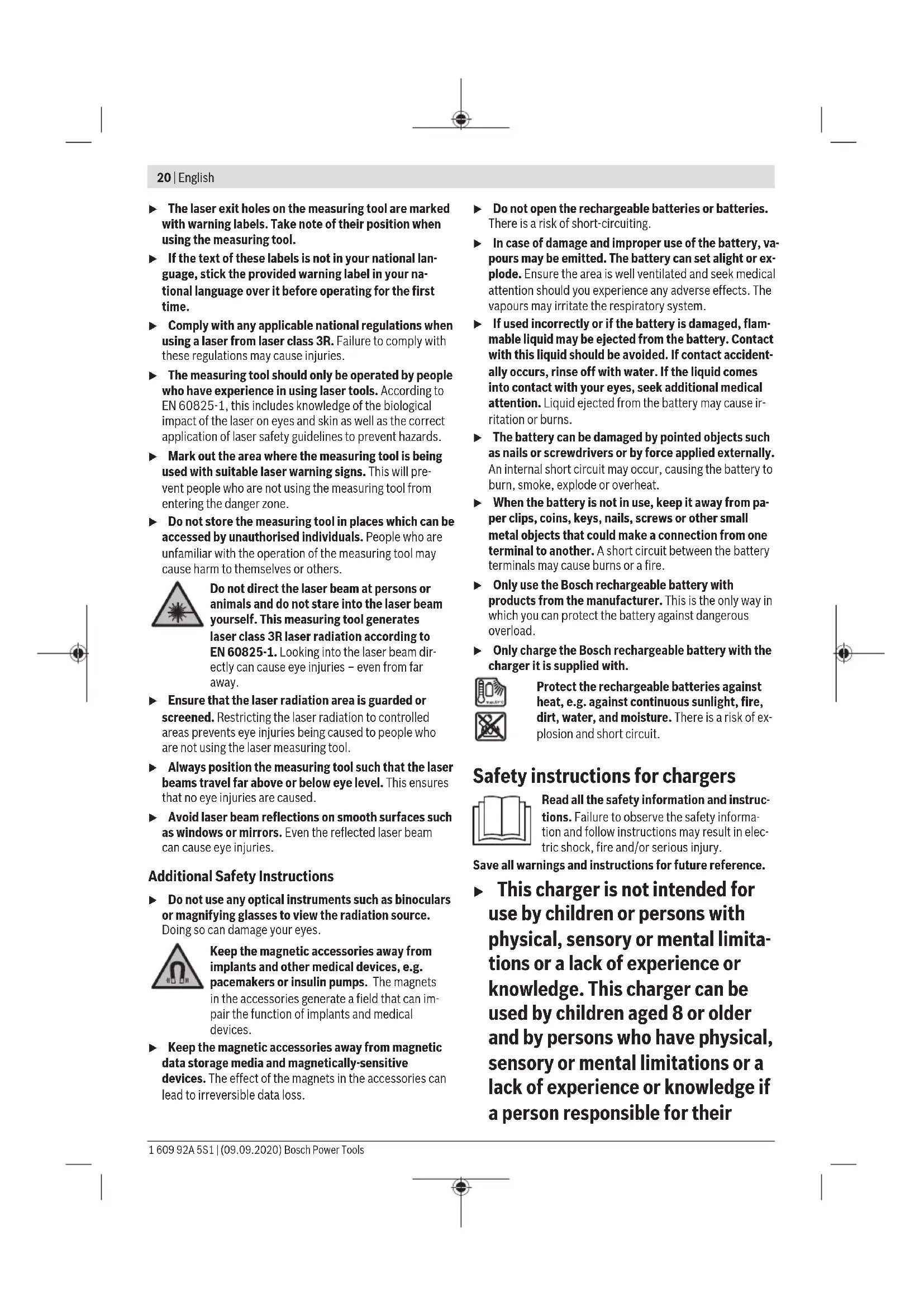
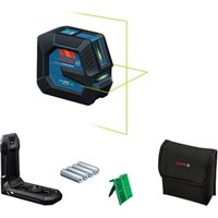
Rotary laser
The measuring tool is intended for establishing and checking exactly horizontal height profiles, vertical lines, alignments and plumb points.
The measuring tool is suitable for indoor and outdoor use.
Remote control
The remote control is intended for controlling the Bosch rotary lasers via infrared.
The remote control is suitable for indoor and outdoor use.
Product Features
The numbering of the product features refers to the illustration of the measuring tool and remote control on the graphics pages.
Rotary laser/charger
(1) Shock warning function indicator
(2) Shock-warning button
(3) Status indicator
(4) On/off button
(5) Rotational operation button
(6) Variable laser beam
(7) Sensor for remote control
(8) Laser beam outlet aperture
(9) Upwards plumb point
(10) Rotation head
(11) Line operation button
(12) Battery warning
(13) Battery pack
(14) Battery compartment
(15) Battery compartment locking mechanism
(16) Locking mechanism of the battery pack
(17) Charging socket
(18)Charger
(19) Mains plug of the charger
(20) Charging connector
(21) 5 / 8 tripod mount
(22) Serial number
(23) Laser warning label
22 | English
(24) Label laser aperture (GRL 300 HV/GRL 300 HVG)
A) Accessories shown or described are not included with the product as standard. You can find the complete selection of accessories in our accessories range.
Remote Control
(25) Remote control
(26) Rotational operation button
(27) Line operation button
(28) Shock-warning reset button
(29) Button for clockwise rotation
(30) Button for anticlockwise rotation
(31) Signal transmission indicator
(32) Infrared beam outlet aperture
(33) Serial number
(34) Battery compartment cover locking mechanism
(35) Battery compartment cover
Accessories/replacement parts
(36) Laser receiver
(37) Measuring rod
(38) Tripod
(39) Fastening screw for wall mount
(40) Fixing holes for wall mount
(41) 5 / 8^n tripod mount for wall mount
(42) Wall mount/alignment unit
(43) Alignment unit bolt
(44) 5 / 8^n screw for wall mount
(45) MagnetA)
(46) Laser viewing glasses
(47) Laser target plate
(48) Case ^A1
A) Accessories shown or described are not included with the product as standard. You can find the complete selection of accessories in our accessories range.
Technical data
| Rotary laser GRL 250 HV GRL 300 HV GRL 300 HVG |
| Article number | 3601 K61 6.. 3601 K61 5.. 3601 K61 7.. |
| Working range (radius)A(B) |
| - without laser receiver, approx. 30 m 30 m 50 m | | | |
| - with laser receiver, approx. 0.5-125 m 0.5-150 m 0.5-150 m | | | |
| Levelling accuracyA(C) | ±3 mm (at 30 m) ±3 mm (at 30 m) ±3 mm (at 30 m) |
| Typical self-levelling range ±8% (±4.6°) ±8% (±4.6°) ±8% (±4.6°) |
| Typical levelling time 15 s 15 s 15 s |
| Rotation speed 150/300/600 min | 150/300/600 min-1 | 150/300/600 min-1 |
| Aperture angle for line operation 10/25/50° | 10/25/50° | |
| Operating temperature | -10°C to +50°C | -10°C to +50°C |
| Storage temperature | -20°C to +70°C | -20°C to +70°C |
| Max. altitude | 2000 m | 2000 m |
| Relative air humidity max. | 90 % | 90 % |
| Pollution degree according to IEC 61010-1 | 2D) | 2D) |
| Laser class | 2 | 3R |
| Laser type | 635 nm, < 1 mW | 635 nm, < 5 mW |
| Divergence | 0.4 mrad (full angle) | 0.4 mrad (full angle) |
| Tripod mount, horizontal | 5/8"-11 | 5/8"-11 |
| Rechargeable batteries (NiMH) | 2 × 1.2 V HR20 (D) | 2 × 1.2 V HR20 (D) |
| (9 Ah) | (9 Ah) |
| Non-rechargeable batteries (alkaline manganese) | 2 × 1.5 VLR20 (D) | 2 × 1.5 VLR20 (D) |
| Weight according to EPTA-Procedure 01:2014 | 1.8 kg | 1.8 kg |
| Dimensions (length × width × height) | 190 × 180 × 170 mm | 190 × 180 × 170 mm |
English|23
Rotary laser GRL 250 HV GRL 300 HV GRL 300 HVG
Protection rating IP 54 (dust and splash- IP 54 (dust and splash- proof) proof) proof)
A) At 25^
B) The working range may be reduced by unfavourable environmental conditions (e.g. direct sunlight).
C) Along the axes
D) Only non-conductive deposits occur, whereby occasional temporary conductivity caused by condensation is expected.
The serial number (22) on the type plate is used to clearly identify your measuring tool.
Battery Charger CHNM1
| Article number | 2610 A15 290 |
| Input voltage V~ 100-240 | |
| Input AC frequency Hz 50/60 | |
| Output voltage V= 3 | |
| Output current A 1.0 | |
| Permitted battery temperature during charging °C 0 to +40 | |
| Charging time | h 14 |
| Number of battery cells | 2 |
| Rated voltage (per battery cell) | V= 1.2 |
| Weight according to EPTA-Procedure 01:2014 | kg 0.12 |
| Protection class | ☐ /II |
| Remote control | RC 1 |
| Article number | 3601K699.. |
| Working rangeA) | 30 m |
| Operating temperature | -10°C to +50°C |
| Storage temperature | -20°C to +70°C |
| Max. altitude | 2000 m |
| Relative air humidity max. | 90 % |
| Pollution degree according to IEC 61010-1 | 2(B) |
| Battery | 1 × 1.5 V LR6 (AA) |
| Weight according to EPTA-Procedure 01:2014 | 0.07 |
A) The working range may be reduced by unfavourable environmental conditions (e.g. direct sunlight).
B) Only non-conductive deposits occur, whereby occasional temporary conductivity caused by condensation is expected.
For clear identification of your remote control, see the serial number (33) on the type plate.
Assembly
Remote Control Power Supply
Using alkali-manganese batteries is recommended to operate the remote control.
To open the battery compartment cover (35), push the locking mechanism (34) in the direction of the arrow and remove the battery compartment cover. Insert the battery.
When inserting the batteries, ensure that the polarity is correct according to the illustration on the inside of the battery compartment.
- Remove the battery from the remote control when not using it for longer periods. The battery can corrode and self-discharge in the remote control during prolonged storage.
The measuring tool can be operated either with commercially available non-rechargeable/rechargeable batteries or with a Bosch battery pack.
Operation with battery pack
Pay attention to the mains voltage. The voltage of the power source must match the voltage specified on the rating plate of the charger.
Charge the battery pack (13) before using for the first time.
The battery pack can only be charged with the charger (18) intended for it.
Insert the appropriate mains plug (19) for your mains supply into the charger (18) and allow it to engage.
Insert the charging connector (20) of the charger into the charging socket (17) of the battery pack (13). Connect the battery charger to the mains supply.
Charging the empty battery pack takes approx. 14 hours.
The charger and battery pack are protected against overcharging.
A battery that is new or has not been used for a longer period does not develop its full capacity until after approx. 5 charging/discharging cycles.
Do not recharge the battery pack (13) after each use, as this will reduce its capacity. Recharge the battery pack only when the battery warning (12) flashes or lights up continuously.
A considerably reduced operating period after charging indicates that the battery pack is used up and must be replaced.
If the battery pack is empty, the measuring tool can also be operated using the charger (18) when connected to the mains supply. Switch the measuring tool off, charge the battery pack for approx. 10 minutes and then switch the measuring tool on again with the battery charger connected.
To change the battery pack (13), turn the locking mechanism (16) to position and pull the battery pack out of the measuring tool. Push a new battery pack into the measuring tool and turn the locking mechanism (16) to position
Take the battery pack out of the measuring tool if you do not intend to use the tool for a long time. Batteries can corrode or self-discharge during prolonged storage in the measuring tool.
Operation with batteries/rechargeable batteries
It is recommended that you use alkaline manganese or rechargeable batteries to operate the measuring tool.
To remove the battery compartment (14), turn the locking mechanism (15) to position full the battery compartment out of the measuring tool and insert the non-rechargeable/rechargeable batteries.
When inserting the batteries, ensure that the polarity is correct according to the illustration on the inside of the battery compartment.
Always replace all the batteries at the same time. Only use batteries from the same manufacturer and which have the same capacity.
Slide the battery compartment (14) into the measuring tool and turn the locking mechanism (15) to position
Take the batteries out of the measuring tool when you are not using it for a prolonged period of time. The batteries can corrode and self-discharge during prolonged storage in the measuring tool.
Charge-control indicator
When the battery warning (12) flashes red for the first time, the measuring tool can still be operated for approx. 2 hours.
When the battery warning (12) lights up red continuously, no further measurements can be taken. The measuring tool switches off automatically after 1 minute.
Operation
Protect the measuring tool and remote control against moisture and direct sunlight.
Do not expose the measuring tool or remote control to any extreme temperatures or variations in temperature. For example, do not leave them in a car for extended periods of time. In case of large variations in temperature, allow the measuring tool and the remote control to adjust to the ambient temperature before putting them into operation. Before continuing work with the measuring tool, always perform an accuracy check (see "Accuracy Check of the Measuring Tool", page 26).
The precision of the measuring tool may be compromised if exposed to extreme temperatures or fluctuations in temperature.
Avoid substantial knocks to the measuring tool and avoid dropping it. Always carry out an accuracy check before continuing work if the measuring tool has been subjected to severe external influences (see "Accuracy Check of the Measuring Tool", page 26).
Starting Operation of the Remote Control
When pressing the operating controls, it is possible to bring the measuring tool out of its level position, so that the rotation is briefly interrupted. This effect is avoided when using the remote control.
The remote control remains ready for operation as long as a battery with sufficient voltage is inserted.
Set up the measuring tool in such a manner that the signals of the remote control can directly reach one of the sensors (7). If the remote control cannot be pointed directly at a sensor, the working range will be reduced. By reflecting the signal (e.g. against walls), the working range can be improved even for indirect signals.
After pressing a button on the remote control, the signal transmission indicator (31) will light up, indicating that a signal has been sent out.
It is not possible to switch the measuring tool on/off with the remote control.
Starting Operation of the rotary laser
- Keep the work area free from obstacles that could reflect or obstruct the laser beam. For example, cover any reflective or shiny surfaces. Do not measure through panes of glass or similar materials. The measurements may be distorted by a reflected or obstructed laser beam.
Setting up the measuring tool
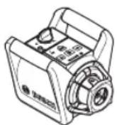
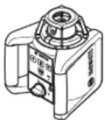
Horizontal position Vertical position
Position the measuring tool on a stable surface in the horizontal or vertical position, mount it on the tripod (38) or on the wall mount (42) with the alignment unit.
Due to its high levelling accuracy, the measuring tool is very sensitive to knocks and vibrations and changes in position. Take care, therefore, that the measuring tool is stable to avoid interruptions to the operation caused by relevelling.
Switching On and Off
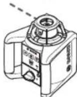
To switch on the measuring tool, press the on/off button (4). All indicators light up briefly. The measuring tool emits the variable laser beam (6) and the upwards plumb point (9) from the outlet apertures (8).
Do not direct the laser beam at persons or animals and do not stare into the laser beam yourself (even from a distance).
The measuring tool immediately starts automatic levelling. During levelling, the status indicator (3) flashes green, the laser does not rotate and flashes.
The measuring tool is levelled in as soon as the status indicator (3) lights up green continuously and the laser lights up continuously. After levelling is completed, the measuring tool automatically starts in rotational operation.
- Never leave the measuring tool unattended when switched on, and ensure the measuring tool is switched off after use. Others may be blinded by the laser beam.
You can already set the operating mode during levelling with the rotational operation button (5) or the line operation button (11). In this case, the measuring tool starts in the set operating mode after levelling is completed.
To switch off the measuring tool, press the on/off button (4) again.
To save the non-rechargeable/rechargeable batteries, the measuring tool is automatically switched off when not within the self-levelling range for more than 2 hours or when the shock warning is actuated for more than 2 hours. Reposition the measuring tool and switch on again.
Operating Modes
Operating Modes Overview
All three operating modes are possible with the measuring tool in horizontal and vertical position.
Rotational operation
Rotational operation is especially recommended when using the laser receiver. It is possible to select between different rotational speeds.

Line operation
In this operating mode, the variable laser beam moves within a defined aperture angle. This increases the visibility of the laser beam in comparison to rotational operation. You can select between different aperture angles.
Point operation
In this operating mode, the best visibility of the variable laser beam can be reached. For example, it is used to easily project heights or to check building lines.
Line and point operation are not suitable for use with the laser receiver (36).

Rotational Operation
Each time after switching on, the measuring tool is in rotational operation mode with standard rotational speed (300min^-1)
To switch from line operation to rotational operation, press the rotational operation button (5) or the rotational operation button (26) on the remote control.
To change the rotational speed, press the rotational operation button (5) or rotational operation button (26) on the remote control until the required speed is reached.
When working with the laser receiver, the highest rotational speed should be set. When not working with the laser receiver, reduce the rotational speed for improved visibility of the laser beam and use the laser googles (46).

Line Operation/Point Operation
To switch to line or point operation, press the line operation button (11) or the line operation button (27) on the remote control.
The measuring tool switches to line operation with the smallest aperture angle.
To change the aperture angle, press the line operation button (11) or the line operation button (27) on the remote control until the required operating mode is achieved. The aperture angle is gradually increased each time it is pressed; at the same time, the rotational speed is increased with each setting.
After the largest aperture angle, the measuring tool switches to point operation after brief post-pulsation. Pressing the line operation button (11) again takes you back to line operation with the smallest aperture angle.
Note: Due to inertia, it is possible for the laser to slightly move beyond the end point of the laser line.
Functions

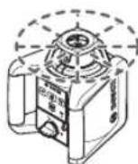
When the measuring tool is in a horizontal position, the laser line or the laser point can be positioned within the rotational plane of the laser. Rotation is possible by 360^ .
For this, manually turn the rotation head (10) to the required position or use the remote control: Press the button for clockwise rotation (29) on the remote control to rotate clockwise, and the button for anticlockwise rotation (30) on the remote control to rotate anticlockwise. In rotational operation, pressing the buttons has no effect.

When the measuring tool is in the vertical position, it is possible to rotate the laser point, laser line or rotational plane around the vertical axis for easy sighting out or parallel alignment in a range of ± 8% .
Press the button for clockwise rotation (29) on the remote control to rotate clockwise.
Press the button for anticlockwise rotation (30) on the remote control to rotate anticlockwise.
Automatic Levelling
Overview
The measuring tool will automatically detect the horizontal or vertical position. To change between the horizontal and the vertical position, switch the measuring tool off, reposition it and switch it on again.
After switching on, the measuring tool checks the horizontal and vertical position and automatically levels out any unevenness within the self-levelling range of approx. ± 8% (± 4.6^)
During levelling, the status indicator (3) flashes green, the laser does not rotate and flashes.
The measuring tool is levelled in as soon as the status indicator (3) lights up green continuously and the laser lights up continuously. After levelling is completed, the measuring tool automatically starts in rotational operation.
When the measuring tool is out-of-level by more than 8% after switching it on or after a position change, levelling in is no longer possible. In this case, the rotor is stopped, the laser flashes and the status indicator (3) continuously lights up red.
Reposition the measuring tool and wait for it to re-level. Without repositioning, the laser is automatically switched off after 2 minutes and the measuring tool after 2 hours.
When the measuring tool is levelled in, it continuously checks the horizontal and vertical position. Re-levelling is automatically performed if there are any position changes.
To avoid faulty measurements, the rotor stops during the levelling process, the laser flashes and the status indicator (3) flashes green.

Shock-Warning Function
The measuring tool has a shock warning function. After position changes or shock to the measuring tool, or in case of ground vibrations, it keeps the measuring tool from levelling in at changed positions, and thus prevents errors caused by a change in the measuring tool's position.
Switching on/activating the shock-warning function:
Press the shock warning button (2). The shock warning indicator (1) lights up green continuously. The shock warning is activated approximately 30 seconds after the shock warning function has been switched on.
Shock warning actuated: If the levelling-accuracy range is exceeded when changing the position of the measuring tool or a severe knock is registered, the shock warning will be actuated. The laser will stop rotating, the laser beam will flash, the status indicator (3) will go out and the shock warning indicator (1) will flash red.
The current operating mode is stored.
After the shock warning has actuated, press the shock warning button (2) on the measuring tool or the shock warning reset button (28) on the remote control. The shock warning function is restarted and the measuring tool starts the leveling. As soon as the measuring tool is levelled in (levelling indicator (3) continuously lights up green), it starts in the stored operating mode.
Now check the position of the laser beam at a reference point and, if necessary, correct the height or alignment of the measuring tool.
When, after the shock warning function has actuated, the function is not restarted by pressing the shock warning button (2) on the measuring tool or the shock warning reset button (28) on the remote control, the laser is automatically switched off after 2 minutes and the measuring tool after 2 hours.
Switching off the shock-warning function: Press the shock-warning button (2) once or, when the shock warning has actuated (shock-warning indicator (1) flashing red), press it twice. When the shock-warning function is switched off, the shock-warning indicator goes out.
Note: The shock warning function cannot be switched on or off with the remote control; it can only be restarted after having actuated.
Influences on Accuracy
The largest influence is exerted by the ambient temperature. In particular, temperature differences that occur from the ground upwards can refract the laser beam.
Since the temperature stratification is greatest at ground level, you should always mount the measuring tool on a tripod for measuring distances of 20m or more. In addition, position the measuring tool in the centre of the work surface, wherever this is possible.
The deviations have an impact on measuring distances of approx. 20m or more, and at 100m the deviation can easily be two to four times larger than that at 20m .
In addition to external influences, device-specific influences (e.g. falls or heavy impacts) can also lead to deviations. For this reason, check the levelling accuracy each time before beginning work.
Should the measuring tool exceed the maximum deviation during one of the tests, please have it repaired by a Bosch after-sales service.
Checking the Levelling Accuracy in a Horizontal Position
For a reliable and precise result, it is recommended that you check there is a free measuring distance of 30 m on firm ground in front of a wall. Carry out a complete measuring procedure for each of the two axes.
- Mount the measuring tool in a horizontal position 30m from the wall on a tripod, or place it on a firm, level surface. Switch on the measuring tool.
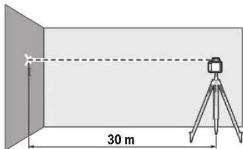
- Once levelling is complete, mark the centre of the laser beam on the wall (point I).
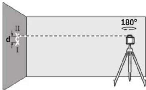
- Rotate the measuring tool 180^ without changing its position. Allow it to level in and mark the centre point of the laser beam on the wall (point II). Note that point II should preferably be positioned vertically above or below point I.
The discrepancy d between the two marked points I and II on the wall reveals the actual height deviation of the measuring tool for the axis being measured.
Repeat the measuring process for the other axis. To do this, turn the measuring tool through 90^ before beginning the measurement.
The maximum permitted deviation on the 30 m measuring distance is as follows:
30m× ± 0.1mm / m = ± 3mm .The discrepancy d between points I and II must therefore amount to no more than 6mm for each of the two measuring processes.
Working Advice
Only the centre of the laser point or laser line must be used for marking. The size of the laser point/the width of the laser line changes depending on the distance.
The laser target plate (47) improves visibility of the laser beam in unfavourable conditions and at greater distances
The reflective surface of the laser target plate (47) improves visibility of the laser line. The transparent surface enables the laser line to be seen from behind the laser target plate.
Working with the Tripod (Accessory)
A tripod offers a stable, height-adjustable support surface for measuring. Place the measuring tool with the 5/8 tripod mount (21) on the thread of the tripod (38). Tighten the measuring tool using the locking screw of the tripod.
On a tripod featuring a measuring scale on its extender, you can set the height deviation straight away.
Roughly align the tripod before switching on the measuring tool.
You can also mount the measuring tool on the wall mount with the alignment unit (42). For this, screw the 5/8 screw (44) of the wall mount into the tripod mount (21) of the measuring tool.
Mounting on a wall: Wall-mounting is advisable, for example for work performed above the maximum extension height of tripods, or for work on unstable surfaces and without tripods.
Fasten the wall mount (42) either to a wall using screws through the fixing holes (40) or to a strip of wall using the fastening screw (39). Fit the wall mount as perpendicular as possible to the wall and ensure it is mounted in a stable way.
Mounting on a tripod: You can also screw the wall mount (42) on to a tripod (41) using the tripod mount on the back. This type of mount is particularly suited to work where the rotation level is supposed to be aligned to a reference line.
You can use the alignment unit to slide the measuring tool vertically (if mounted on the wall) or horizontally (if mounted on a tripod) up to approx. 16cm . To do this, loosen the bolt (43) on the alignment unit, slide the measuring tool into the required position, and retighten the bolt (43).
Working with the Laser Receiver (accessory)
Use the laser receiver (36) to improve detection of the laser lines in adverse lighting conditions (bright environment, direct sunlight) and over greater distances.
For rotary lasers with multiple operating modes, select the horizontal or vertical operation with the highest rotational speed.
Before working with the laser receiver, read and observe the laser receiver operating instructions.
28|English
Working with the Remote Control
When pressing the operating controls, it is possible to bring the measuring tool out of its level position, so that the rotation is briefly interrupted. This effect is avoided when using the remote control.
Sensors (7) for the remote control are located on three sides of the measuring tool, including above the control panel on the front.
To check levels or apply slopes, it is recommended to use the measuring rod (37) together with the laser receiver. A relative measuring scale is incorporated at the top of the measuring rod (37). You can preselect its zero at the bottom on the extender. This enables you to read deviations from the target height straight away.
Laser Goggles (Accessory)
The laser goggles filter out ambient light. This makes the light of the laser appear brighter to the eye.
Do not use the laser goggles (accessory) as protective goggles. The laser goggles make the laser beam easier to see; they do not protect you against laser radiation.
Do not use the laser goggles (accessory) as sunglasses or while driving. The laser goggles do not provide full UV protection and impair your ability to see colours.
Example applications
Position the measuring tool in the horizontal position on a firm support or mount it on a tripod (38) (accessory).
Working with a tripod: Set the laser beam at the required height. Project or check the height at the target location.
Working without a tripod: Determine the height difference between the laser beam and the height at the reference point using the laser target plate (47). Project or check the height difference measured at the target location.
When right angles are to be projected or partition walls are to be aligned, the upwards plumb point (9) must be aligned in parallel, meaning at the same distance to a reference line (e.g. a wall).
For this, set up the measuring tool in the vertical position and position it in such a manner that the upwards plumb point runs approximately parallel to the reference line.
For the exact positioning, measure the clearance between the upwards plumb point and reference line directly on the measuring tool using the laser target plate (47). Measure the
clearance between the upwards plumb point and reference line again as far away as possible from the measuring tool. Align the upwards plumb point in such a manner that it has the same clearance to the reference line as when measured directly at the measuring tool.
The right angle to the upwards plumb point (9) is indicated by the variable laser beam (6).
To indicate a perpendicular or a vertical plane, set up the measuring tool in the vertical position. When the vertical plane is supposed to run at a right angle to a reference line (e.g. a wall), align the upwards plumb point (9) with this reference line.
The perpendicular plane is indicated by the variable laser beam (6).
To align the vertical laser line or the rotational plane against a reference point on a wall, set up the measuring tool in the vertical position, and roughly align the laser line or the rotational plane with the reference point. For precise alignment with the reference point, turn the rotational plane around the

vertical axis (see "Turning the Rotational Plane when in the Vertical Position (see figure B)", page 26).
Under favourable light conditions (dark environment) and for short distances, it is possible to work without the laser receiver. For improved visibility of the laser beam, either select line operation or point operation and rotate the laser beam to the target location.
In unfavourable lighting conditions (bright environment, direct sunlight) and for larger distances, use the laser receiver to improve detection of the laser beam (36). When working with the laser receiver, select rotational operation with the highest rotational speed.
When measuring over long distances, the laser receiver (36) must be used to find the laser beam. In order to reduce interferences, the measuring tool should always be set up in the centre of the work surface and on a tripod.
The laser receiver (36) should always be used when working outdoors.
When working on unstable ground, mount the measuring tool on the tripod (38). Always work with the shock warning function activated in order to avoid faulty measurements in case of ground movements or shocks to the measuring tool.
Overview of the rotary laser indicators
| Laser beam Rotation of the laser beam | Green Red Green Red |
| Switching on the measuring tool (1 s self-check) | | ● ● ● | | |
| Levelling in or re-levelling 2 ×/s o 2 ×/s | | | | |
| Measuring tool levelled in/ready for operation ● ● ● | | | | |
| Self-levelling range exceeded 2 ×/s o ● | | | | |
| Shock warning function activated ● | | | | |
| Shock warning actuated 2 ×/s o 2 ×/s | | | | |
| Non-rechargeable/rechargeable battery voltage for ≤ 2 h operation | | | | 2 ×/s |
| Non-rechargeable/rechargeable batteries empty | ○○ ● | | | |
- Continuous operation
2 × /s: Flashing frequency (e.g. twice per second)
o: Function stopped
Maintenance and Service
Maintenance and Cleaning
Keep the measuring tool, charger and the remote control clean at all times.
Do not immerse the measuring tool, charger and remote control into water or other fluids.
Wipe off any dirt using a damp, soft cloth. Do not use any detergents or solvents.
In particular, regularly clean the surfaces at the outlet aperture of the laser on the measuring tool and make sure to check for any lint.
After-Sales Service and Application Service
Our after-sales service responds to your questions concerning maintenance and repair of your product as well as spare parts. You can find explosion drawings and information on spare parts at: www.bosch-pt.com
The Bosch product use advice team will be happy to help you with any questions about our products and their accessories.
In all correspondence and spare parts orders, please always include the 10-digit article number given on the nameplate of the product.
Malaysia
Robert Bosch Sdn. Bhd.(220975-V) PT/SMY
No.8A,Jalan 13/6
46200 Petaling Jaya
Selangor
Tel.: (03) 79663194
Toll-Free: 1800 880188
Fax: (03) 79583838
E-Mail: kiathoe.chong@my.bosch.com
www.bosch-pt.com.my
Great Britain
Robert Bosch Ltd. (B.S.C.)
P.O.Box 98
Broadwater Park
North Orbital Road
Denham Uxbridge
UB95HJ
At www.bosch-pt.co.uk you can order spare parts or arrange the collection of a product in need of servicing or repair.
Tel. Service: (0344) 7360109
E-Mail: boschservicecentre@bosch.com
You can find further service addresses at:
www.bosch-pt.com/serviceaddresses
Disposal

Electrical and electronic equipment, batteries, accessories and packaging should be sorted for environmentally friendly recycling.

Do not dispose of electrical and electronic equipment and batteries in household waste!
Only for EU countries:
In accordance with Directive 2012/19/EU and Directive 2006/66/EC respectively, electrical and electronic equipment that is no longer usable and defective/drained batteries must be collected separately and recycled in an environmentally friendly manner.
Français
Robert Bosch Morocco SARL
53, Rue Lieutenant Mahroud Mohamed
20300 Casablanca
Tel.: +212 5 29 31 43 27
E-Mail: sav.outillage@ma.bosch.com
France
Robert Bosch (France) S.A.S.
www.bosch-pt.com/serviceaddresses
ParaATTERALo: 1) To do so, consider the following steps.
Calle Robert Bosch No. 405
C.P. 50071 Zona Industrial, Toluca - Estado de Mexico
Tel.: (52) 55 528430-62
Tel.:8006271286
www.bosch-pt.com/serviceaddresses
Eliminación

www.bosch-pt.com/serviceaddresses
Eliminação

www.bosch-pt.com/serviceaddresses
Smaltimento

www.bosch-pt.com/serviceaddresses
Afvalverwijdering

Bosch Service Center
Telegrafvej 3
2750 Ballerup
På www.bosch-pt.dk kan der online bestilles reservedele el-ler oprettes en reparations ordre.
Tlf. Service Center: 44898855
Fax:44898755
E-Mail: vaerktoej@dk.bosch.com
www.bosch-pt.com/serviceaddresses
Bortskaffelse

Bosch Service Center
Telegrafvej 3
2750 Ballerup
Danmark
Tel.: (08) 7501820 (inom Sverige)
Fax: (011) 187691
Du hittar fler kontaktuppgifter till service har:
www.bosch-pt.com/serviceaddresses
Avfallshantering

Endast for EU-lander:
Tilbehār/reservedeler
(36) Lasermottaker
(37) Nivellerstang
(38) Stativ
(39) Vegholderens festeskrue
(40) Veggholderens festehull
(41) Veggholderens 5 / 8^n -stativfeste
(42) Veggholder/justeringsenhet
(43) Skrue på justeringsenheten
(44) Veggholderens 5/8"skrue
(45) Magnet
(46) Lasersiktebrille
(47) Lasermaltavle
(48) Koffert
A) Ilustrert eller beskrevet tilbehor ingar违法犯罪 standard- leveransen.Det komplette tilbehoret finner du i vart tilbehorsprogram.
Tekniske data
www.bosch-pt.com/serviceaddresses
Kassering

www.bosch-pt.com/serviceaddresses
Havitys

TpoBoaKataKOpPou/KaTeou eIneBou (Bene Eikova H)
Tia nTv evdei nia catakopupncn, avaloya, iac katheta enapaveiac npene va theoet to opyavo metponc otny katheta thon. O'avto katoe eninebo npeneva elvai oepoh ywia me ia ypaun avapopac (n.x. tolxoc), tote euuypamite to onie katakopupou npoc ta naov (9) ae autn tn ypaun avapopac.
H kaTeoc eepavizetai eow Tnc metabnTc akrivac aeicep (6).
Euoyapmuon katakopou/kαθeou eunéosou (βλe nεkova I)
Tia va euyupauioge Tnypaun lizep n to eninebo nepirotpnpc baoe evoc oneiou avapopac enaw oe evav toio tonoetnote to opyavo metponc otnv kaetn thean kai euyupamite npoxepa tn ypaun lizep n, avaloya, to emine do nepirotpnpc me to oneio avapopac. Ta nTv akipn euuypaumon sto oneio avapopac yuplote to enine do
πeipotpocvγup ano tv kaθeto aOva (βλeε «
Πeipotpocn Tou enieδou πeipotpocn oe πepintwn
kaθetnc θeont (βλeε eikova B)》,Σελiδa 129).

Epyaia xwpic dektn aeicep (bne eikova J)
EpyaOla eBekTn AeiZeP (Aeene Ekova K)
Se nepintwn duouevov ouvOnkov fwioou (oWTeivno nepiAlAiov, aueon naiakn akTivoBoia) kai oe yalec anootaoeic vya Tnv kalute np avixvean tnc aktivaac leizep xnpoiotei rofektn leizep 36).Tia va epyaoteire me tov defktn leizep npenei va enieEte Tnv nepiotpopikn aeitoupyia me tn myiot taxutnta nepiotpophc.
Metpnon oe ydaec aootaec (baene ekova L)
Kata t n eptn opeyalec anoaroeic npenei va xpouponontheta o kctnc letep (36) ia tv evtomopo tnc aktivac letep. Ia va pewoete tic napebolec, npenei va tonotheire to opyavo mptnoq navtoe atn jean tnc emapveiaec epyaiaic kal naaw o' evav tpinoda.
Epyaia oTov eWtepko χoPo (βλeπε eKóva E)
Tov eWTePiko Xwpo npenei va xpnoioieitai navtoe o 6ektnc IeIep (36).
Kata tyn epyaia o aotoh enipaveia stipncs ouvapuooynto opyavo metpnanc naww oe evav trinoda (38).Epyaceo mvo me evpyonoinevn Tn aeitoupyia npoeioboinc kpaadaiw, yia tn anopuyn
AaOc metpnooeov oe nepintwn tuxov kivnon tc nnc enipaveiaoc otpiENCn kpaabaow tou opyavou mertponc..
EnoknonnTwv evdeieewv Tou nepotpoukou aeizep
www.bosch-pt.com/serviceaddresses
Anoupon

Oi nAekptikec ouakeuec, oI enavaopoptojevec
unatapiec/umatapiec, ta eapntmuata kai oI
ouakeuaie c npetie va avakukawovtai pe tpoio
piko npoc to nepiaalov.

Mny pixyete Tc nAektpiec ockeuek cai tic enavaopnpioevec umatapiec/umatapiec oiaikaka anoppipmuata!
Moyo yia xopec tnc EE:
Uuovva pe Tnv Eupnaiok nyia 2012/19/EE o axpnoTe c nkepikec oukeuec kai oupwva pe Tnv Eupwnaiok nyia 2006/66/EK oi xaaovec npaunopoinvec enavaopnpoevec mpatpiec/matapie penei va oulambdaoyovtai Exwipota via va avakukawouv me tropo piliko npoc to npipalauov.
Türkce
www.bosch-pt.com/serviceaddresses
Tasfiye

Robert Bosch Sp. z o.o.
www.bosch-pt.com/serviceaddresses
Utylizacja odpadów

www.bosch-pt.com/serviceaddresses
Likvidace

www.bosch-pt.com/serviceaddresses
Likvidácia

www.bosch-pt.com/serviceaddresses
Hulladékzeelés

IaTn3rOToBnEHHyKa3HaHaNocNeHHeCTpaHnue 0bIOKKnPyKOBoDCTBa HnHa KOpnye NdEHH.
KoHTaKTHa HnΦopMaun OTHOCHTbHo HmnpTepa CoepKHTcHa yNakOBKe.
Cpok cnyy6bH3dennn
Cpok Cnyk6bln3dennno Coctabnre7 7net. He pekomehyet cK3cknnyaataun no ncteeynn 5 net xpaehnnc da tbl n3rotobneHn 6e3 npedbapntelbHO npOBepkn (daty n3rotobneHn cm. Ha 3TNKeTke).
IpeueeHb KpntHuecknx OTka3OB H OwH6OHyBle DeiCTBnepcoHana Hnn NOnb3OBaTeN
-HeHCNOB3OBaTbPnIPOBHeHNDbIMaHENOPpeCTBeHHO H3 Kopnyca H3eJIN
-HeHCNoB3OBaTbHaOTKpbITOMIPOCTpaHCTBEBOBPMAdoXJa(BpaCnblnEMoBOe)
- He BkIIOUaTb npH nonaDaHn BOdb I KOpNyC
Kpntepnn ppeenbblx coctoHHN
He yctahabnbaTe MaHHTbIe npHaadneKHOCTN B6JIH3H MMnPaHTAOB INpOuHX MeDnHHckx annapaTOB, HAp., KApDHocTHMyTOpOB HHCyHnHOBbIX HAcOCOB. HaxoJrueceB pHaHAdneXHoCTx MaHHTbI co3da
KOT MaHHTHOE NONE, KOTOPOE MOKET OKa3bIBaTb BINHAHHe Ha pa6Oty HmNlaHTaHTOB MMeDnHcknx aannapaTOB.
Depxte MarHHTbIe npHaadJnxHOCTN BdAnOT MarHHTbIX HcHTeNei DaHHbIX N OT npH6OpOB, yBCTBNTbHbIX K MaHHTHomY NOIO. Bo3JeICTBHe MaHHTOB npHaadJnxHOCTe MOKET npHBODITb K HEBOCnONHMoN NOTEpe daHHbx.
He OTKpbBaTe aKKymyTOpbHnn 6aTpe. Pn3 TOM B03HnKaET ONaCHOCTb KOPOTKTO 3aMbkaHnR.
PnIOBpeKdennH HeHaIeKaueM HcNoIb30BaHHn aKKymyIaTopa MoKeT BblIeNHTbcra3. AKKymyIaTOp MOKeT BO3rOpaTBcH Nn B3pIbAITcR.O6ecneUte npnTOK CBexero BO3dyxa H nPi BO3HKnHOBeHH nnAo6 o6paTNTecb K BpaU. Ra3blMOrY Bbl3BaTb pa3dpaxHe NdxaTeNbHbIX PyTei.
Pn Hn HnpaBnHOM nCnOB3OBAHN H3 aKkyMnyIopa MoXeT NoteYb KnKIOCTb. N36eraTe COnpNkoCHOBEN C Hei. Pn CnyaHOM KOHTAKTE IpomOITE COOTBETCTByIOoee MeTO BDOJ. Ecn 3Ta KnKIOCTb NOAET B rna3a, To DonONHtEnbHO o6paNTecb 3a NOMOuB K BPauy. BiteKaIOUaA kKMyIaTOPHaJ XnKOCTb MoXe T pNBcTn K pa3DpaKeHHO KOHN HIN K OKO-ram.
OctpbIMn PpeMeTaMn, KAK HAp., rBo3dEm HnH OTBepTKo, a TaKKe BHeuHM CInOBbIM BO3dEChTBem MOxHO NOBpeHTb AKKyMyaTOpHy 6aTapeo.3To MOXET npHBecTH K BHYTpEHemy KOPOTKOMy 3aMbikaHHO, BO3rOpAHIO C 3aDblmHeHEM, B3pbBy HnN nepepeBy akKymyIaTOpHoi 6aTapei.
3aunuata He HncnOb3yembl AkkymnTOp OT KaHcIepcknx CKePnOK, MoHET, KInoue, rBO3JeB, BHNTOB H npyrnx MaHehKx MetaIIHueCKNx PpeMeTOB, KOtOpbie MOrY T3akopoTnB nIOca. KopOTKoe 3aMbKaHne nIOICOB aKKymnTOp oMaKet pNBecTH N OKO-tam nnnoKapy.
NcnoIb3yIte BoschakKymIaTOp TOnbKO B H3dJIeHX n3rOToBHTe. TOnbKO TaK aKKMyIaTOp 3aunueH OT onachOH neperpy3Kn.
3apkaTe BoschaKmyTOp TOnbKO C NOMOuB 3apdHbIX yCTpoIcTB, BXoAunx B KOMnEKT NOCTAB- KN.
3aunuaneakkymnyatopbiOTBbICOKX TemnepaTp, Hanpimep, OTdnttehBOHa rpeBaHHa coHnce,OTOrH,pr3N,BoDm Bnarn. CyueCTByeTOnaCHOctb B3pbIBa N KOpTko 3amblKaHH.
Yka3aHnno TcHexnke 6e3oNaChocTN dna 3apAdbix yctpoNCTB

IpoouTME Bce yka3aHHH HnHCTpyKuHH No texHnke 6e3oNaChOcTH. HecobkIoJeHne yka3aHHNo TEXHnke 6e3oNaChOcTH HnHCTpyKuMH MoKet npBecTN K npaxKeHHo 3NeKtpN
uecknTOKOM,poKApyH/INTNRAKeNbIM TpaBMaM.
CoxpahnTe 3TH HNCTpyKuH N yKa3aHn Dn6yduero nOJIb3OBAHn.
3To 3apraHoe yctpoiCTBO He npedHa3nueHo dIy HcNoB3OBAHHa DeTbMn IuIaMn C orpaHn-yeHHbIMn cHncOpHbIMN UIN yMCTBeHHbIMn CnoCo6HOCTAMN INHHeIOCTaTOUHbIM ONbITOM N3HaHnA. PONb3OBaTbC A3TNM 3apraHbIM yCTPOiCTBOM DeTAM B BO3pacte 8 let n CTapwe N IuIaM C orpaHnueHHbIMn cHn3Nu-yeCKHM, CEHCOPHBIM NIN yMCTBeHHbIMn CNOco6HOCTaMn INN C HeIOCTaTOUHbIM ONbITOM N3HaHNrMaP3pe7aeTcA TOIbKO NOI pINCMOTpOM OTBETCTBEHHORO 3aNX 6e3oNaCHOCTb IuIa NIN ecNN OHI npoIIN HHCTpyKtAX Ha npedMet NaEXHORO NCNoB3OBAHNA 3apraHoro yCTPOiCTBa N IOHmAOT, KaKHe ONaCHOCTN HCxOJATOT Hero. IHaue cyIeCTByet ONaCHOCTb HepaBnIbHO rCNoB3OBAHN IIN IOnyuEHn TpaBM.
PnncMaTpBaNTe 3a DeTbMn BO Bpemn0nb3OBaHH, npn BbInonHeHHN OunchKn N Texo6cnyXBaHH. Pn n ATOM CneHnTe 3a Tem, yTo-6bl dETn He nrgan 3apAnhblm UcTPOINCTBOM.
3apjkaTe TOnbKO Bosch aKKymyIaTOpbl NiCd/NiMH emKocTbIO 9A-4 (ot 2 aKKymyIaTOpHbIX 3JeMeHTOB).HaPjaXeHne aKKymyIaTopa DOnxHO NODxOJNTb K 3apJaHOMy HAnpJXeHHIO 3apJdHOrO
yctpoicBa.He 3apkaite He3a- pkaemble 6atapen. Hnue cyuceCTByeT ONaCHOCTb Ioxapa N B3pbIbA
3aunuatae 3apnHoe yctpoNCTBO OTdoxnn CbIPOCTH.IPOHNKHOBEHHe BObl B 3neKTponpnpOp NOBbIaETPNCNopaxenH 3neKTPOTOKOM.
3apKaIte H3MePHTeNbHbINHCTpyMeNToNkoC NoMoUbO 3apAHOYcTPOHCTBa,BXODaEeroB KOMIINEKT NOCTABKN.
Copekhte 3apAnoe yctpoCTBO B uHCTOTE.Bpe3yntate 3arpa3HeHn cyueCTByet OaCHOCTb 3neKTPn-yeCKORO nopaxehna.
Kakdbi pa3 neped hcnonb3oBaHem npOBepnTe 3a pAHOe yCTPOIcTBO, uHyp n WTEKepe. He nCOnb3yte 3apAnHOe yCTPOIcTBO, ecnn o6hApXeHbI NOBpeXeH H. He BCKpbIBaIte 3apAnHOe yCTPOIcTBO CaMOCTO TELHo, erp peMOHT pa3peuaeTcBblONHrTb TOnbKO KBANHmnpOBaHHOMy NEPCOHany H TOBko CNCNOb- 30BAHHeOpHnHaJIbHbIX 3anuaCTei. NOpBXeHNHbIe 3apAnHbe yCTPOIcTBA, uHyp n WTEKepe NOBbIaOT PnCK npaJxEHn 3neKTpoTOKOM.
He hcnolb3yIte 3apJHoe yCTpoIcTBO Ha nERKOBocnnaMeHHoUeCn NOBepXHOCTN (HaP., Ha 6ymare,TKaHx H.T.D.) HIN B NOXkapOONacHO CpeE. B CB3n CHaRpeBaHEm 3apJHOrO yCTpoIcTBA BO BpeM 3apJKNBO3HNKaET ONaCHOCTb BO3ROPaHH.
Onncahne npoodykta n ycnyr
Poxanycta,co6nlaate nlloctpaunB hauane pykoBODCTBa no 3Kcnnyataun.
PpimHeHnNoHa3NaeHHo
PoTaunOHbI Ja3epHbI HHBenHp
H3MePHTeBbHb HcTpyMeH NTpeHa3haueH dIa ONpeDeneH H NPOBepKbTOUHO TOpH3OHTaJIbHbIX IHHN, BepTHKaJIbHbIXIIHHN, IIHHN CXOda HOTBCOB.
H3mePteIbHbI HnCTpyMeHT npHroDeH Dnpa60tB BHytpnOMeueHn Ha OTKpbITOM Bo3dyXe.
TynbTnctaHOnHO ynpBneHH
IynbTINCTaHUNHOrOynpaBHeHHnpEnHa3NaeHnDnI ynpaBHeHH Bosch-potaHOnHHbIMnA3epHbIMn HNBenpaMn NocpeCTBOMNfPpakpachoro n3nyehn.
IyntdctaHOnHOrOynpAbHeHHnPnroEeHnPa60tB BHTPNOMeHnHaOTKpbITOMBO3dyXe.
H306paXeHHbIe COCTaBHbIe yACTM
Hymepaun H3o6paXeHHbIX KOMnOHeHTOB BbINONHeHa IPO pncyHKam N3MepnteHbHO rHCTpyMeHTa N yIbTaIcTahC uOHHO ynpabHeHH CTpaHnuax C H3o6paXeHHaMn.
190|Pycckn
PoTaunHbI Na3epHbI HNBenp/3apdHoe yctpoiCTBO
(1) INHdkatop fuyHKuIN npeDynpexKeHHn o cotpceHHN
(2)KhoIIKa BkIIOeHnI pIeDyIpyKeJdEHnO COTpIcEHn
(3) INHДИКATOP COCTOЯнna
(4) BbiknouaTeNb
(5) KhoNka potaunOHoro peKnMa
(6) N3meHembI na3epHbI nyu
(7)Датчндостаньногу ураленя.
(8) OTeBepCTne IaIy BbIXOda IaIePnHO lyuA
(9)ToukaOTBeca,IpoeunpyemarBbepx
(10)PotaHONHaIroNobKa
(11) KhoIIka nnHeHoro peKIma
(12)PpeynpeKdHne o p3paJxehHoCTn 6aTapei
(13) AKKymyIaTOpHbI 6nok
(14) OTeckdIa6batapei
(15)ФИКСТОРOTCEKAДЯББАТЕN
(16)ΦHKCaTOPaKKyMnyTOpHOro 6noka
(17)3apnHoe rheaO
(18)3apnHoeyctpoiCTBO
(19) CeteBaB BnIka 3apdHoro yCTpoiCTBaA
(20) 3apnHbI WTeKepe
(21) THe3do noD uTaTHB 5/8"
(22) CepiHbI HOMep
(23) Ppeynpeintelbna Ta6nka na3epHoro n3nyeHHa
(24) PpeynpeHntelbna TaBnUka OTBepCTnIyIa BxOda na3epHoro lyuA (GRL 300 HV/GRL 300 HVG)
A) N3o6paXeHHbIe MIn OnncAHbIe npHaNdxKHOCTn HE Bxo- dT B cTaNAPThBIO6bEM NOCTABKN. POnHbI aCCOPTMENT npHaNdxKHOCTe Bbl HaJeTe B haWe npPorpAMMe npHaNdxKHOCTe.
IynbT dNcTaHnOHHoro ynpaBHeHH
(25) NylbT nIcTaHnIOHnHO ynpaBHeHH
(26) Khonka potaunohoro pekima
(27) KhoNka HneHOro peKnMa
(28) KhoNka c6pOca npEynpEeJHnO cOTpcHn
(29) KhoNka noBopoTa no yacoboi cTepeKe
(30) KhoNka noBOPota npOTNB acBOBc CTpeKN
(31) INHINKATOP OTnpaBKN CHRHaJa
(32) OTeBepTne DnB BbIXoDa HnHpaKpaPacHOrO n3nyeHn
(33) CepHnHbH HOMep
(34) ΦИКСАТОР КБИШКи 6aTapeйHorO OТсЕКa
(35) Kpbuika baTaapeHoro OTecka
PnHadneXHoCTn/3anaChbIe yactn
(36) Na3ePbHb npHeMHNK
(37)ДальномернаяpeиKaA)
(38)UtaTnB
(39) KpenexkhbI BnHT NaTeHHoro KpePneHnA
(40) KpenexHbte OTBepCTnHaCTeHHOro KpenIeHnA
(41) THe3do noD uTaHb 5/8" nHa HacteHHoro KpeHneHN
(42)HacteHHoe KpenneHne/Y3en BbIeBpkn
(43) BnHT BbIpaBnHbAioJero 6NoKa
(44) BnHT 5/8" hacteHHoro KpennneHnA
(45) MaHTnT A
(46) Oukn dna pa6oTbI cnaepHBm INHCTpyMeHTOM
(47) BnHpHa MapKaДЯlaIa3ePHorуyaA
(48)ФуTNЯP
A) N3o6paXeHHbIe Hnn OnilcaHHbIe npHnAdneKHOCTHe BxoDHTB CTAHdAPThbIO6bEM NOCTABKN. PONHbI accOPTMENTpHnAdNeKHOCTe Bbl HaJeTe B haWei npPorpMaMe npHnAdneKHOCTe.
Texnueckne daHbIe
BCTaBbTeOTcEKN76atapei(14)BN3MePHTeHbHbI
HHTpymENT H NOBepHnTE qHKCaTOp (15) B noJooKeHne
N3BNEkaTe 6aTapeH HnAkkymyIaTObI N3MepHe TELBOHO HHCTpMeHTa, ECIN IPODOJXHTeJIbHO BpeMa He 6ydeTe pa6oTa b C Hm. Ppi dInTeJIbHOM XpaHEHH B IN3MepNTeJIbHOM INCTpyMeHTe BO3MOxHa KoppO-3Hn I camOpa3pJaKa 6aTaapeE h AKKMyIaTOpOB.
Hdkatop CTeneHH 3apXeHHoCTn
Ecnn npdunpexdeHne o pa3paXeHHocn 6aTapeu (12) Mnaet B nepBbI pa3 KpaCHbIM CBETOM, h3MePHTenbHn HnCTpymENT MOKHO NCONlb3OBaTB eue 2 yaca.
Ecn npdpynpckdeHne o pa3paekHHocn 6aTapei (12)
CBETTCa HnpepbIBHO,daBHeIWe n3MepeHn HeBO3
MOXHbI. Yepe3 1 MHN. pa60Tb I3MePHTeBHBi HNCTpyMeHT aBTOMaTHueCKN BbIKIOyaeTcR.
Pa6ota c nHcTpymeHTOM
3aunuataHe H3MePHTeIbHbI HHCtpyMeNT nynbT dCTaHnOHnHO ynpabEnHa OT BnArn n npmBX CONHeHbIX nyue.
He noDBepraTe H3MePHTeBbHbI HnCTpyMeH nnybT dNCTaHcunOHHO ynpabLeHHa BO3dEChTBIO 3KCTpeMaNbHbIX TemnepaTpH TemnepaTpHy NepenadoB. He octabnIte, Hanpimep, IN HA dInntelbHoe BpemBaTOMo6Hne. Ppi 3HaunTEbHbIX KOle6aHHx TemnepaTy pbl DaIte H3MePHTeBHomY HnCTpyMeHTy INyIbTy hCtAHcUNOHHO ynpabLeHHa neped BKIOueHHem Chauana CTabHN3nPoBaT bTemnepaTy, npexJe Ym BkIOuOAtb IN. PpexJe Ym pOdoJIXaTb paOToTc C n3MePHTeBbHM HnCTpyMeHToM, Bcerda BblONHNe IpoBepKy erO ToHOCTH (CM. KoHTpONb TOUHOCTn H3MePHTeBHO nHCTpyMeHTa", Ctpanua 195).
3KCTpeMaIbHbIe TEMepaTyI NTEMepaTyIbe IpePnAdbMOrT OTPuCaTeBHO BnIyTb Ha TOUHOCTb H3MePHTeBHO INCHTpymEHTa.
H36eraTe CNbHbIX TOnKOB NnadeHn H3MePnteBHO HOHCTpyMeHTa. Iocne CNbHbIX BHeUHX BO3deiCTBn HA H3MEpNTeHBn IHCTpyMeHT peKOMeHnyETcnpOBepNb erO ToHOCtB, npexKe yem npoDoJXaTb pa6oTaB C H3CTpyMeHTom (cm. KoHTpONb ToHOCtN H3MePnteBHO IHCTpyMeHTa", CtpaHnca 195).
3anyck npnbta dncctanuohnoro ynpabneHnB 3KcnnyatauH
PnHaxaTHKHOJNOKynpaBHeHHMOXHO BbIeCTN3MepeTEnbHmHCTpyMeHT N3 BbIPOBHeHHORO NIOJOKeHHaBpaSeHHe HeHaDIOROocTaHOBHcTc.3TOrMOxHO 36eKaTb,HCNoB3yryNytDnCTaHNOHHOrO ynpaBHeHH.
CMOMeHTa yCTaHOBKn 6aTApEn CDOCTaOuHbIM HAnpIaeKeHNEMyIbT DnCTaHcUHOrO ynpabHeHraTOB KpaOte.
YctaHOBHe 3MepeHtIbHbI INCTpyMeHTaK, YTO6bl CnHAnOT NyIbTa DnCTaHcIOHO ynpabNeHr DOxOJIN DO OHO rN3 DaTUnKOB (7) NO npAMo. Ecn NytBt DnCTaHcIOHOynpaBHeHr He MoKET 6bITb HappaBHe pRMA Ho DaTnK, paOch nnana3OH cokpaaetc. OTPaKeHne CnHaHa (HaPIMep, OT CTeH) MOKET CHOBA yBeNnuHTb DaIbHoCTb DeNCTBn DaKe npHnEPMOM CnHane.
Nocne haxaTHKONKNHa nybIte DCtauHNOHHO ynpabLeHHN CBeueHHe INHdkatopa OTnpaBKn CnHana (31) yka3blBaET HA TO, 4TO OTnpaBnEeTc HnH.
BkHouHe/HbIKHouHe H3MepeHteHbHO HHCTpyMeHTa C nOMOuHIO NylTa HnCTaHnOHHO ynpabNeHn HEBO3MOKHO.
Haayano pa6oTb co cTpoNTbHbIM na3epom
Ocbo6oHTe pa6oyu 30Hy ot npenatCTBn, KOTOpbIe MOrTy OTPaKaTb HnN NepeKpbIBaTb Na3epHbI NyU. PnKpOte OTPaKaIOuNe I 6NecTtue NOBepxHOctH. He npon3BOJTe N3MepeHHy uee3 OKOHbIe CTeKnla
HnHaNoHnHbIe MaTePhaIbI. Pe3yNbTaTbI N3MepeHn MoYr 6bITb NcKaXeHb I3-3a OTPaXeHn Hn NepeKpbITn Na3epHoro Nyu.
YcTaHObKa N3MePHTeBHoRo HnCTpyMeHa
TOpH3OHTaIbHOe NOLOXKeHHe BepTHKaIbHOe NOLOXKeHne YCTAHOBITe N3MEpHTaIbHbI HNCTpyMeHT Ha IPOUHYO ONOPyB TOpH3OHTaIbHOe INN BepTHKaIbHOe NOLOXKeHne, MOHTIPyTe IHCTpyMeHT Ha IITaTINB (38) INN HA HAcTeHHoe KpePJIeHHe (42) cyJlOM BBiBepKn.
H3-3a BbICOKO TcHOCTH HBeINPOBAHN H3MEpNTeNBbH INHCTpyMeHT pearnyet Oeyb YyBCTNBtEBHO Ha KONE6AH N H3MeHeHHI NOJKeHHN.CneITNE PO3TOMY 3a CTa6NBbIM NNOJKeHHEM H3MEpNTeNBHO INHCTpyMeHTa, YTO6bl NCKIOuHTb NepebpBBb B paBOte H3-3a dONOLHTeNBHO HBeINPOBAHn.
BkIIOueHHe/BbIKIOueHHe
UTo6bI BKNIOHTb N3MepHTeNBHbIN HcTpyMeHT,HaKMnTe Ha BbIKNoaTeB (4).Bce INHnKaTOpbI HeHaOnIO 3aroprTa. N3MepHTeNBbHINHCTpyMeHT N3LyuaET N3MeHReMbI Na3epHbI Lyu (6)NTOky OTBeCa BBepx (9)N3BbIXoNbIx OTBepCtn (8).
He HanpaBnIe Na3epHbI Nyu Ha IIOe Hnn XNBOHbIX HcMOTpTe Camn B Na3epHbI Nyu, B Tom Yncne n c6oJbWoO paccToHHa.
H3mePHTeBbHINHCTpyMeHT cpa3y Je npOn3BOaHT aTOMaTHueckoe HNBENIPOBaHHe. BnpOecce HNBENIPOBAHn HINDKaTOP COCTOHHN (3) Miraet 3eneHBIM CBETOM, Na3ep He BpaaetcH MIRaet.
N3MePHTeBbHb HNCTpyMeHT BbIPOBHe, KaK TOnbKO HNDKATOP COCTOHHa (3) 3aRopaetc3eHebIM CBeTOM, a Na3ep RopHT HnpepbHb. No 3aBepWeHH HNBENPOBaHH N3MePHTeBbHb HNCTpyMeHT ABTomuYeCKBKNIOUaETcB PoTaQHOHHo PekHM.
He octabnIte H3MepntbHbI HNCTpyMeT 6e3 npncmOTpa N BbIKIOaYte H3MepntbHbI HNCTpyMeT NOcNE HCNOB3OBAHNA. Dpyrne Iua MOry T 6bITb OCenIIeHbI Na3epHbIM NyOM.
BbMoKeTe ycTaHoBNtbpaooyupeKxHmUyBeNpoEcce HnBeInpOBAHHaKNoIKo potaunOHOrOpexkMa(5)nn KHOKnO KoIINHeHOro peXkMa(11).B3OM cnyae n3MePeTbHbI INCTpyMeHT 3aNyckaetc B Bbl6paHHom paOeyem peXkMe Nocne 3aBepWeHHaHnBeInpOBAHHa.
YTO6bI BBIKIOHTb N3MePHTeBBHbHINHCTpyMeHT,CHOBa HAKMITE Ha BbIKIOHTaeNB (4).
IJIa3aunTb6batapennnAkkymnyTopoB n3MePnteHbHINHCTpymENT ABTomatNuecCKn BbIKIIouaeTc,ecn OH HaxO-NTCBAHE nnana30Ha CaMOHNBeNIpOBaHHa 6Oone 2 Hnncn PnpynpeKdHeNe O cOTpcceHH paOtaet B TeueHne
60ee 24. YcTaHOBHe N3MepnTeIbHbI HNCTpyMeHT N CHOBA BKIOUHTeero.
Pexhmbi pa6oTbi
063oppexHmOBpa6oTbI
Bce 3 peKIma pa60tby BO3MOxHbI npri rOpN3OHTaNbHOM I BepTKaJIbHOM NIOJKeHHN 3MEpeHTbHOro HHCTpyMeHtA.
PotaunHbI peKHM
PotaHnHHb peKHM peKOMeHnyetcOoc6ehHO npnpnMEnEHn na3epHoro npneMHnka. MoKHO Bbl6npaTb pa3nHuBle CKOPoCTN BpaueHna.

Пинэндь рекнм
B3TOM pexKIMpepa60bI 3MmEeMbI na- 3epHbI Lyu DBNkETcB O rpaHnueHHOM yrne pactbopa. Bnaorapar 3tOMy ynyu 7aetc BNDIMOCb Ia3epHOrO lyua nO cpaBHeHIO CpoTaIOHHbIM pexHMOM. BblMOKeTe yCTaHABINBaTb pa3NIuHbI yron pactbopa.
ToueyhnyeKHM
B3OM peknme pa6oTbIOCTHraETc HAnnyuwa BNDIMOCt bN3MeHReMOro Na3epHoroNyua. OH cnYkNT, HanpImep, nI npocTo rnopeHoCA roPnOHTanee nnIpnOBepKn Nnn CxOda.
HHeHbH ToeHbpeKHMb He npHa3HaueHbIpa-60TbCnA3epHbIM pPnEMHKOM (36).

PotaunohhhpeXMM
Iocne BkHoueHHN3MepeHtBbHINHCTpyMeHT HaxOHTcB BpoaOHHom pexHMe CO cTaHapTHoN CKOpOCTbIO BpaueHHN (300MH-1).
ДлпpeкнioчEHиИннeHOrOpeKIMaBpoTauHOHbI HAKMITE KONky poTaUHOHoro peKIMa(5)NII KONky poTAuHOHOropeKIMa(26)HaIyNbTeIINCTaHIOHOHOrO ynpabHeHn.
ДлгИЗМЕнEHСКОРСТВБАSUHENHAЖIMаTe KHO附KPO- TaUNOHOROPeKIMa(5)INN KHO附KpyOTAUHONHOpeKIMa(26)HaNyIbTe INCTaHUNOHORO ynpAByeHHNEHeCKoJIbKOpa3, nOKaHaNcPnEE He NOBHTcHEO6xOHMaCKOPocTb.
Pn pa6oTe c napeHbIM npHeMHNKOM peKOMeHyetycTaHaBnBaTb MaKcHMaJIbHyIO ckOpcTb BpaUeHINr. Pn pa6oTax 63 napeHOrO npHeMHNka HcNoIb3yIte MehBuYIO ckPoCtB BpaUeHINr, YTO5bI yIyUWHTb BIDHMocTb napeHOrO LyuA, IN cNoIb3yIte OUK dra pa6oTb C napeHbIMNHCTpyMeHTEM (46).

JIHHHbI pexHM/ToueHbI pexHM
IJIpeKIOUeHbBIIHeHbIpeKIMmHnTOueHbIpeKIM HAIXMITE KHOKNy IINHeHORo peKIMMa (11) HN KHOKNy
JIINHeHORopeXnMa(27)HaIyIbTeIHCtAnuHOHorO ynpaB-
H3mePteIbHbI INHCTpyMeHT nepeKJIIOuAeTcB IINHeHbI peXHM C HAnMeHbUHM yrIOM pAcTBopa.
IINMHeHnYrna pactbopa HxKHMaTe Ha KHOKNy HneHOro peKmma (11) INN KHONky IInHeHOro peKmma (27) HA NylBe INCTAHIOHHO YnpaBHeHn HECKOBko pa3, NOKa HnDCnlee He NOBNTCA HeO6XOnMbIpeKm. YrOlaPactbopa YBeHNuBaETCnO3TanHO C KaXdbIM HaxaTHEm,B TO Xe BpemcKOpocTb BpaueHn HapacTaet C KaXdbIM 3Ta-nOM.
IIO DocTHKeHHM MaKCHMaJIbHO rYrna pAcTBOpa H3MepeHTeBHy INCTpyMeHT NepExoJNT BTOueHy bpeKm Iocne He npdoONKteBHO B6paun. NOBtOphoe HaxaTne KONKNIINHeHOrO peKmA (11) BO3Bpaaaet INCTpyMeHT BInHHeHbpeKm C HAnMeHbShm Yrnom pAcTBOpa.
Yka3aHHe:Ipo npuHHe HHePTHocn Ia3ep MoKet CJIerKa BbIXOHTb 3a KOHeUhble ToUKN Ia3epHOIINHN.
Функцн

TIOBOPOTHHH/HTOCKBROP3OHTaNbHOe B HNOCKOCTBpaueHn (cm.pnc.A)
EcHn H3MePHTeHbI INHCTpyMeHT paCNOJoxHe RopN 3OHTaJIbHO, Na3epHyIO NHHIO NII Na3epHyIO TOky MoKHO paCNOJoxHb INpeJenax NIOCKoCTN BpaueHna3epa. IOBOPOT BO3MOxHe Ha 360^
ДлгЗТОВуРУHIO NOBEPHITe POtaUHOHHYIO rOIOBky (10) B HeOBxODmOE NIOJOKeHne HIN NcNOnb3yTe NpIbT dNCTaHcUHOHOro ynpabJIeHn: YTO6bI NOBepHyTB NO YACOBOH CTpeJIke, HaxMITE KONKy «ПОБOT NO YACOBOH CTpeJIke» (29) H aNyIbTe INCTaHcUHOHHORO yIpaBJIeHn, YTO6bI NOBepHyTB nPoTINb YACOBOH CTpeJIKN, HaxMITE KONKy «ПОБOT nPoTINb YACOBOH CTpeJIKN» H aNyIbTe INCTaHcUHOHHorO ynpabJIeHn (30). B PotaUHOHHOM peKIMMe KONKN He pa6OtaIOT.

Bnpouecce HnBeHnpoBaHHn HnDnKatop CoCTOHHN (3) Mnaet 3eHbIM CBETOM, Na3ep He BpaaaetcN Mnraet.
H3mePHTeBHy HnCTpyMeHT BbIPOBHe, KaK TOnbKO HnIKaTOp COCTOHHA (3) 3aropaeTc 3eneHbIM CBETOM, a na3epropHT HepepbHO. No 3aBepeHn HnBeInpoBaHHa N3MePHTeBHy HnCTpyMeHT ABtOMaTueCKN BKIOUaTeC B POtaQHOHHOM PEXIME.
Ecnnn3mepntbHbHnHnCTpyMeHTyMeet yKIOH 60Jee
Yem8%nocne BKNIOUeHnHnNocne H3MeHeHHnNOJOxHe
HNBENIPOBaHHe 6OJIbHe HeBO3MOxHO. B 3TOM cIyae
BpaueHHe npEkaaTeC, na3ep mHaet, a HnIKaTOp
COCTOHnH (3) npoONJHKTeBHO rOPHT KpAChbIM CBeTom.
PacnoJOKHe n3MepeNTbHbHnHCTpyMeHT 3aHOBO nNoO
XdTe, noka He npOEt ABTOMaTHueCKoe CaMOHNBoHNPOBAHHe. Be3 n3MeHeHHnNOJOKeHHnNA3ep ABTOMaTHueCKn
OTKnIOUaETcHpe3 2 MHN, a H3MePeNTbHbHn HnCTpyMeHT -
pee3 24.
HnBeHnPOBaHHbI H3MepeTeIbHbI HNCTpyMeHT NOCTOHHo IPOBepaET CBOE ROPINOTAbHO EIN BEPTKAnbHO NIOJKeHHe. Pn H3MeHEnn NIOXeHn ABTOMATuecckn PpOn3- BODITCA CAMOHnBENPObAHne. YTo6bI N36ExaTb OUn6OK n3-MpeHn, BpaueHne OCTaHaBNBaetcBO BpEmr IpOceCa HnBeHnPOBaHHa, Na3ep MnaeT, a HnDkATOp COCTOHHA (3) MNFaet 3eJIeHbIM CBETOM.

Функци npedynpekdeHnO cOTpcEHn
H3mepntelbHbI HNCTpyMeHT OcHaueH fynKcHne npedynpexJeHHo o COTpaeHHx. Pn H3MeHeHH NIOJKeHH, COptceHHx H3MepntelbHO rHCTpyMeHTa HIN Bv6paHHrpyHTa 3a FyHKcH NpeDToBpaAaet CamOHNBENIpOBAHNE HOBOM NIOJKeHH N, TaKIM O6pa3OM, OUn6KN, Bbl3bBAeMbIe CdBHROM H3mepntelbHO rHCTpyMeHTa.
BkJIOueHHe/AKTbBaunI npdeynpeXeHNn o cOTpReHNH:
HaKMITE KONKY BKNIOUeHn NpeDynpExeHnO cOTpcEHHN (2). INHdkaTOp NpeDynpExeHnO cOTpcEHHN (1) npoJOnKHTeBHO rOpHT 3eHehBM CBeTom. NpeDynpExeHne O cOTpcEHHN AKTHBnpyetcN pPmepHo uepe3 30 c nocNe BKnIOUeHn FyHKuN NpeDynpExeHn O cOTpcEHHN.
CpaabaBHaHne npEynpeXeHHn o cotpcHHn:ecnn Hnana3OH TOUHOCTn HBeHnPOBaHHn PpeBbIeH nPi HmMeHeHHn IIOXKeHHn N3MePHTeBHorO INCTpyMeHTa nn peHCTpaHHn CnBHo HorO yDapa, cpaabaBaeT npEynpeXeHHne OcotpcHHn:BpaueHne na3epaepaacetcna3epHbIy MHTaET, INDkaTOP COCTOHHN (3) rachET, a INDkaTOP npEynpeXeHHn O cotpcHHn (1) MHTaET KpaCHbIM CBEtom.
Tekyu np pexkmpa60bbydctcoxpaHEn.
PnBbIKIOHOM npEynpEKeHHN OcotpcEHN HaKMNTe KHONKY BKNIOHEn npEynpeKeHHN O
cotpceHn (2)Ha n3MePHTeBHom HNCTpyMeTe Nn KHO Ky BkUOueHHn PnpEynpKDeHHo O cotpaceHH (28) Ha nyIbTe INCTaHNOHHoro UnpaBHeHH. FyHKuIN PnpEynpK DeHHo COTpceHH INpe3aNcyTcTc, IN3MePHTeBbHbIN HHCTpyMeHT 3aNYcKaET HbENHPOBaHne. KaK ToIbKO IN3MePHTeBbHbIN HHCTpyMeHT BbIPOBHrCn (INdNKATOp COCTOHn (3) NOCToHHO TropHT 3eNEHbIM CBetOM), OH ABTOmatueckn 3aNYcKaETCB COxpaHEHOM pexmpe pa60tbl. IpoBepbTe nONoxHeHn Na3epHOro Lyya no pepeHOn TouKe IN pIn Heo6XoDMocTH IOKnOPpeKTHpyte BbICOTy INn opEnHTaunIO IN3MePHTeBHO INCHpyMeHTa.
Ecnpncpabotabwem npedynpexdeHmOcotpcEHn
fhykun He 3anyckaeTc CHOBa HaxkaTmem KhoNKn BKIOUeH
Hn pedynpexdeHHoCOTpcEHn (2)Ha n3MePHTbHOM
HhCTpyMeHTe Hn KHONK c6poca npedynpexdeHHo
COTpcEHn (28) Ha nyIbte INCTaHNoHHOro ynpabHeHH,
na3ep aBtOMaTHueCKn OTKIOUaTeCHpe3 2MH, a n3MePHTbHbIH hNCTpyMeHT -yepe3 2.
BbIKIOueHne fynKcNIN ppeynpexdeHnO cOTpcEHn: HAKMITE OJHOKpaTHO KHOKNY BKNIOUeHn INpeynpexdeHn O cOTpcEHn (2) INN INPN BbIKIOUeHHOM INpeynpexdeHn O cOTpcEHn (INDNKATOP INpeynpexdeHn O cOTpcEHn (1) MIRaET KPAChbIM CBeTOM) -DBAxkbI. Ecn INpeynpexdeHne O cOTpcEHn BbIKIOUeHO, INDNKATOp INpeynpexdeHn O cOTpcEHn IacHT.
Yka3aHHe: C NOMOuBIO NybTa DnCTA HUHOHORO ynpaBneHnIyHKnIpyeynPpeKdEHN OcotpcEHn He MOKeT 6bITb BkIOueHa HnBbIKIOueHa, a MOKeT 6bITb nepezany-ueHa TOnbKO nOcNE cpaBaTBaHn.
KoHTpOJIb TOUHOCTn H3MePHTeJIbHOrO HHCTpyMEnTa
ΦaKToPbI, BnHryOuUne Ha ToUHOCTb
HanboBuee BnHHe Ha ToUHcTb Oka3bIaBt OKpyKaIOua TemepaTypa.BoObeHHocTH TempeaTpHybI nepeNaIbI, HMeIOuHe MeTo NO Mepe ydaHHe OT NoBbI, MOrY TcTaB npHuHO ONKIOHHeHaZepHoroLyua.
NocKoIbky nepenad TemnepaTypbHan6Oone OouTmB6IIN3n rpyHTa,ToHa yuactkax dInHoC bBiwe 20M n3MePnteHbHbHnHCTpymEt CneDyET yctaHaBnBaTb Ha wTaTHB.KpOMe TOrO,yCTaHaBnBaTe H3MePnteHbHbHnHCTpymET,NO B03MOXHOCTH,BcepeDnHe pa6Oey nIoUaDi.
OTKNOHEHNA CTAHOBATCA CYIeCTBHeHHIM HAHNHc pa cctOHHN OK.20 M;Ha paccToHHN 100 MOH BnONHe MOrYT BBOE H DaXe BcETBepo NpeBbIaTb OTKNOHEHNE, HMeIOUec Ha pacCTOHHN B 20 M.
Hapy C BHeHHMn BO3eJCTBmH, CneuHueckne IIN HCTpymeHa BO3eJCTBn (HaNP., PAnEHNn HnCnBhIe yApbl) TaKke MOrT npNBOuNTb K OTKnOHeHNM. PO3tOMy BCerda Npeed Haayamop paobTo pOBepRte ToHocb HnBe-
EcnB BO Bpemr OJHOH 3 npOBepOK n3mpeTEnbHbI HNCTpyMeHT pReBbICHT MaKcHMaJIbHO DOyCTHMoe OTKIOHeHne,OTaIte erO B peMOHT BCepBcHcyIO MacTepeckyIO Bosch.
IpoBepKa TOnHocTH HNBENHPOBaHH B ROpH3OHTaJIbHOM nONoXeHH
Ha yyactke 30 M MaKcMaIbHO dOnyCTHMoe OTKIOHeHHe COCTaBnEeT:
30 M × ±0,1 MM/M = ±3 MM. TaKHM o6pa3OM, paccToHHe d MeKJy TouKaMn I n II npn KaKJIOm H3 ObeHX npOeIpy H3MepeHHN He DOnKHO ppeBbIaTb MaKc. 6 MM.
Yka3aHHn no npMmeHnHIO
Ncnonb3yIte Bcerda TOnbko CepeHny na3epHOH TOU KINn Na3epHOH NHHN DnOtMeTKn. Pa3Mep Na3epHOH ToUKn/WHpHNa HAp3epHOH NHHN MeHReTcB 3aBNCMOCTN OT pacctoHnR.
Pa60TbC Bn3HpHoN MapKo (cm.pnc.C)
Bn3npna Mapka (47) ynyuetaET BnDnMoCTb na3epHoro ly-ya npn He6laoropnTbIx ycNoBnx Ha 6oNbux pacctoHnX.
OtpaKaIOUaI NOBepXHocTb BN3HpHOI MapKn (47) yNyUwAe T BnIMOCt b Na3epHOI NINHn, Hn P03paHOn NOBepXHOCTN Na3epHyIO NINHIO TaKke BnHO C TbIBHO CTOpOHbI BN3HpHOI MapKn.
Pa6oTa co 7aTbBOM (nPnHaDneKHOCTb)
TtATNB oecneuHbAe c7a6nIbHyIO, perynnpemyIO NO BblCote ONOpY dIra N3MepeHNI. YcTAHOte N3MePHTeNbHBI INCTpyMEHT HRezDOM IOI tATNB 5/8" (21) HA pe3b6y TtATNBA (38). 3aФнксPyTe N3MePHTeNbHBI INCTpyMEHT C NOMOJIbIO KpeJENHO BnHTaTNaB.
Ha 7aTHe b pa3MepHOH ⅢKaiOn Ha BbDnKHOH qactN MOxHO HeNoCpeIcTBeHHO yCTaHOBtB CMeueHne NO BBICOTe.
PpeBapntbHO BbipOBHnTe WtAtnB, npexde yem BKIOuatb N3mepntbHb HNCTpyMENT.
Pa6oTa c HacteHbIM KpeIeHnEM WM 4 (npHnAdnHexKHOCTb) (cm. pnc. D)
BbMOKeTe yCTaHOHBt N3MePHTeNBHbH NHTpyMeHT Ha HAcTeHHoe KpeJIeHneC NOMOuBb BO BpApBnBaIOUeRo 6Ioka (42).ДЯТоуЗakpyTHe BHT5/8"(44)HAcTeHHoTO KpeJIeHnB RTHe3Do NOJ WTaTbB (21)Ha N3MePHTeNBHom HHCTpyMeHTe.
MOHTAX Ha CTeyH: MOHTaX Ha CTeyH peKOMeHdyETcH, HAnpHMeP, IIN pa60t Ha BbICote, INpeBbIaIOuEi BbICOTy BbIDNKeHH WtATnBa, INI pIn pa6Ote Ha HeycToUHBOI NOBepxHOCTn 6e3 WtATnBa.
PnPKpyTHe HAcTeHHoe KpeNpEHHe (42) BHTAMM CKBO3b KpeNExKhIe OTBepCTHg (40) K CTHe NIN PnPi NmOuN KpeNEXHO BnHTa (39) K PnAhnke. MoHTpyNe HAcTeHHoe KpeNpEHHe KaK MoXHo 6oJe eOTBeCHO K CTHe N CneJNTe 3a HAdexHcOCTbIO KpeNpEHHa.
MoHTax Ha 1aTHBe: Bb TaKKe MoKTe PnKpyTtB HaCTeHHoe KpeIeHne (42) B rHe3do NpO tTaTHB (41) c3aHnTaTHBa. 3To KpeIeHne Oc6eHNo peKoMeHdyETc dIpa-8ot, B KOtOpbIX pNOCKOCT bPaAeHnN DOJXHa 6bITb BbIPOBHeHA OTHOCHTeHbPOpenepHO IINHN.
C NOMOJIbO BbIpaBHBaIOUe 6NOKa Bbl MoKTe nepemeMaTb yCTAHOBNEHHbI H3MepHTeHbHbI HnCTpyMeHT NO BepTKaII (npH MOHTaXe Ha CTHe) INI NO rOpH3oHTaII (npH MOHTaXe HA WtATHe) B npeJEnax npHM.16 cm.ДЯ 3TOr Ocna6Be BVHT (43)Ha BbIpaBHBaIOUe 6NKe, nepemECTNe Tn3MEpHTeHbHbI HnCTpyMeHT B Heo6xOdImoe nONoxeHne HCHOBA 3aTaNHTe BVHT (43).
Pa60Ta c na3ePbIIM npHeMHNKOM (npHnHaIIeXHoCtB)
PnH6bnaropnraTHOcBSeHNOCTn(CINbHOeOCBSeHne,PnMbteCOHNHeYbNy)Ha60nbompacctoAHN DnIyUwero HaxoxKeHHa3epHBix INHHNHCNoB3yTe Ia3epHbI pnpemHNK(36).
Ecnn CnpontenbHbH naep HmeeT Heckonbko peXnMoB pa60tbl, Bb6epnte ropn3oHTanbHbH nHn BeptnKaIbHbH peKIM C cAmO BBICOKO CKOPoCTbIO BpaueHn.
Ja pa6oTbI cIa3epHbIM npHemHHKOM, O3HaKOMbTeCb C no-LOXKeHnMIu IeNCTByTE B COOTBeTcBn C DaHHbIM pyKOBODCTBOM NO 3KcIIpyataun.
Pa60a c npbTom dctanHnHO npabneHH
PnHaxaTHKONOKynpaBHeHHMOxHO BbIBeCTN3MepTeNbHmHCTpyMeHT N3 BbIPOBHeHHO NOIOKeHHa,TAKTOBpaSeHHeHaNOrO OCTaHOBTc.3TOro MoXHO 36eKaTb,NCNoB3yA NyblTINCTaHUNOHHOynpaBHeHHa.
DAtuNn(7)HCTaHUNHOO ynpabHeHna pacNOJKeHbI C Tpex CTOpOH N3MepeHbHO rHCTpyMeHTa, B TOM uCNe HAD NaHEnbO ynpabHeHn Cpeepi.
Pa6oTa c JaIbHOMePHo peKoN (npHHaIeXHocTb) (cM.pHC.E)
Длпюверкн Неровстей И поевocа Нахною peKOMeHnyetcN HCNoIb3ObaT DAJIbHOMepHyo peKy (37) c na-3eρнblmnpneMHNKOM.
Ha daIbHOMepHO peKe (37) BBepx HaHeceHa OTHOCnTeIbHAR 1KJala.Hynb 3aJaETcB HN3y Ha BblBHXHO qACTn.5NaOpa 3tOMy MoXHO cpa3y BuJeTb OTKnHOeHHo OT 3aDaHHOB BICOTbl.
OuKnIpa60bIcna3epHbIM HhCTpymENTOM (npHaadnHexHoctb)
NaeepHbIe OOKN OTpMbTPOBbIAHOT OKpykaIOuC BcET. NToTMyCBET Na3epa KaXeTc8 BoJeE RPKM DnA 3PntEnbHO BOCINPAH.
He hcnb3yte ouKn dIpa6oTbI c na3epHbIM HnCTpyMeHToM (npHaJnxKHOCTb) B KaueCTBe 3aunTbIX ouKOB. OuKn dIpa6oTbI c na3epHbIM HnCTpyMeHToM oBecneuBAOT lyuwee paCno3HaBaHne na3epHoro Lyua, Ho He 3aunuAoiT OT na3epHoro n3nyeHna.
He hcnolb3yIe ouKn Ipa6oTbI c na3epHbIM HnCTpyMeHTOM (pnpHaIeXHOCTb) B KaueCTBe CONH 3aunTHbIX OOKOB HIN 3a pyneM. OKn Ipa6oTbIC nasepOM He oecneuBaHOT 3aunTy OT YΦ-H3nyeHnN MeuaOIT PpaBnHOMY CBETOBOCPnATIO.
PpIMepbI BO3MOXHbIX BnDOb pa6oTbI
NpeHoc/npOBepKa BbICOTbl (cm.pnc.F)
YCTaHOBHTe H3MePHTeIbHbI INHCTpyMeHT B TOpH3OHTaIbHOM NOIOXKeHH Na IPOUHOE OCHOBaHHe NIM MOHTpyIte ERO HA WtATHB (38) (pINHaNDJekHOCTb).
Pa60aTO cIITABOM: HAnpaBte Na3epHbI Lyu Ha HyKHyOBbICOTy. IpepeHeCTe HIN PpOBepBe BbICOTy B Heo6xOHNOM MeCTe.
Pa60a 6e3 WtATnBa: OnpeDenTe pa3HNuB B BVICOTe MeKdy Na3epHBIM LyHOM n pepeHOI TOOK NpH NOMOIN B3NHPHOI MAPK (47). IpepeHCte Hnn PPOBepbTe H3MepeHHyUo pa3HOCTb B BVICOTE B HYKHOM MecTe.
PapannelbHoe HnpanpBHeHne ToKn OTBeca, npoeunpyemOB BBepx/HaHeceHne npambyx yrnoB (cm.pnc.G)
EcHn Heo6xOJHMo pa3MeTb npMbIe yIbI nn yCTaHOBtB npomexkyTOuHbI cTeHbI, TO TOcKy OTBeCa, npoeUnpyEmyIO BBepx, (9) cneJyET HanpaBHT NapannelbHo, T. e. HaOnHaKOBOM pacctOAHHH K pepepHoiHH (HanpMep, K CTHe).
ДлгэТоу yctahOBHTe n3MePHTeHbHn HnCTpyMeHT B BepTHKaIbHoe nOToJKeHne n pacnoJIOXHTe erO TaK, YTO6bl ToUka OTBeca, npoeuPyemar BBepx, npoxoJnna npn6n3TeBHO npapannelbHo KpenepHo nnHH.
TTOHORO N3NHOHPOBAHNA H3MepbTe paCCTOHNE MEXKdy TOOKO OTBeCA, PPOeUpyEmo BBepx, INpepHON HNNHe HENOCPeDCTBENHO HA H3MePHTbHom IHCTpyMeHTe pIN NOMOu BN3NPHO MapKn Dnla3epHOrO Lyua (47).
H3mepbTe pacctoHHe MeJxNy ToKoI OTBeca, IpoeuPyE MoB BBepx, HpenepHO nnHne CHOBa Ha KaK MOXHO 60nbem paccToHHn OT H3mepHTeBHOrHO nHCTpyMeHa.
HanpaBbTe ToKy OTBeCA, npoeuPyemyIO BBepx, TaK, yTo6bl OHa 6bla Ha Tom Ke pacCToHnn OT peNepHO nnHnn, YTO n npn H3MepeHHn HENOCpeDCTBeHHO Ha H3MePHTenbHOM IHCTpymente.
PpMoI yOrO tOHcHtJIbHO TOUKN OTBeCA, npoeuHpyEmoB BBepx, (9) OTo6paKaAeTcN3MeHReMbIM Na3epHbIM LyyOM (6).
Pa3MeKa BeptHKaH/BeptHKaBHOI NIOCKOCTN (CM.PHC.H)
Дя pa3MeTkn BepTKaJIH HnB BepTKaJIbHOI nIOCKOCTn YCTaHOBHTe N3MepHTeJIbHbI INHCTpyMeHT B BepTKaJIbHOe nIOJKeHHe. EcIN BepTKaJIbHbA INoCKOCTb npoxOHT NOI pRbIM yTlOM K pepeHoi IINHH (HaNP., CTHe), TOrDa BblPOBHrTe TOUY OTBeCA, IpoeuHpyEMyIO BBepx, (9) no 3ToI pepeHoi IINHH.
BepnkaIb OTo6paKaETcH3MeHReMbIM Na3epHbIM LyuOM (6).
Hymepaia 3o6paKeHHX KOMnoHeTIB NocnnaeTbca Ha 3o6paKeHHB MIPIOBaIbHO rHO IHCTpyMeHTa 3 NybTom DnCTaHuiHO ynpabIIHHA CTOpIHkax 3 MaIOHNkAMn.
PotauiHnna3ep/3apAHH npHCTpi
(1)IHHKAtopfynHkiiIInonepdHexHHnpoCTpyc
(2) Khonka «Понерджени постус »
(3) INDINKaTop cTaNH
(4)Виимкаду
(5) Khonka potauiHoro peKmY
(6)3mHHnIa3epHnI npOMiNb
(7)ДатчндяпьтадиctаниногуkepyBaHHA
(8) Buxidn O Tbip nnaapehoro npomeHa
(9) Touka Bncka, cnpmaMoBaHa BVropy
(10)PotauiHa rOiBka
(11) Khonka liinHoro peXnMy
(12) INДиКаТОрЗapяДжЕностiбатарeйok
(13) AkymyIaTOpHn 6loK
(14) Cekijdnybatapehok
(15)ΦikcaropceukiiJn6aapeiok
(16) Φικατορ ακυμηλτορθόσι δύποκα
(17)3aepnHe rH3o
(18)3aPAnHnI npncTpiiA
(19)UTeTencB 3apAHorO npnCTpoA
(20) 3apdHnH wTeKepeA
(21)TnizniuTatBv5/8"
(22) CepiHnH HOpem
202|YkpaHcbKa
(23) NopepdxkyBaIbHa Ta6nUka npo60Tu 3 na3epom
(24) PonepejxvBaIbHa Ta6nUka OTBOpy IINBHXOy na3epHoro npomEna (GRL 300 HV/GRL 300 HVG)
A) 3o6paXeHe a6o onnca He npnaIaIb HxOaITb B CTaHapTmH o6cH IOCTaBKn. IOBHn acOpTHMeHT npnaIaIb Bn 3haJeTe Haui nporpaM i npnaIaIb.
IynbT ductaniiHoro KepyBaHHa
(25) NytbT dHCTaHJIHORo KepyBaHHA
(26) Khonka potauiiHoro peKmMy
(27) Khonka lihiHoro peXnMy
(28) KhoNka cKnDaHnneonepeDxKeHH npo cTpyc
(29) Khonka nobopoTy 3a cTpiKIOI rOIOHHNHa
(30) KhoIIka noBOPOpy npoIT cpiIKn roHnHa
(31) INdikaTop BiDpaBneHn HcHnany
(32) OTrBip DnBHXOy IHpaepBOHO BINPOMIHOBAHH
(33) CepiHnHOMep
(34)ΦikcatopcekiiIgbaapeiok
(35) Kpùnka ceküiДЯбаṭaŋeɪk
PpnaJ4/3aunactHH
(36) ΜαερΗν ἡπημαγ
(37)Далекомірна peиka
(38) LITaTINB
(39)KpinnbHn rBnHT hactiHHoro KpinneHHRA
(40) Kpiinblhi OTbopn HactiHHoro KpinnneHHA
(41)Гиздпштатв5/8"нг actiHOrO kpinneHHA
(42) HacTiHHe KpInnneHHa/NpncTpiDnBnPiBHOBaHnA
(43) ΓΒΗΝΙΤΗ ΜΑνρίβιΒΗΝΑβλήθουΜγ δύομι(A)
(44) [BnHT 5/8" HactiHHO KpInneHHA]
(45)Marhit
(46) OkyIpy nI py po60Tu 3 na3epoM
(47) Bi3npHn 1 nTAl
(48) y npa^A
A) 36paXeHe a6o onnca He npnaJa He BxOHTb B CTaHapTHmOBcTnocTbKn. NobHn acOpTmEnpHaJaBn3aIdTe B hawin nporpaM npnaJa
TexhiuHa
BydibenbHn naep GRL 250 HV GRL 300 HV GRL 300 HVG
6aTapeKa MoKe KOPOyBaTH y nIbTi dNCTAHnIHORO KepyBaHH I cAmOp03paJkATnC.
KMBHNEHHBHMIPIOBbHOro iHcTpymeHa
BmipobalbHn iHCTpymeHT moKe npauOBaN BiD 3BnuaHnx 6atapeNOK uK akymyIaTOpIB aO bIa akymyIaTOpHOrO 6noka Bosch.
EkcnnyatauaB iD akymytnopHoro 6noka
3BaxaIte Ha Hanpyry B Mepexi! HanpyraJxepena KINBHeHH MaE BiNObiDaTH DaHIM Ha 3aBOcBki Tabnucj3apdHoro npncTPO.
3apnItbakymyIaTOPHH6nOK(13)nepeepnHBMKOpHCTaHHM.AkymyIaTOPHH6nOKMOXHa 3apJkaTH
nHweynepe6aehomydIyzbo3apndHomny npncptoi(18).
BCTABTe WtencelbHy BnIky, 10 niJxOaHb IyBaWoI mepexi (19), y3apAHH npucptpi (18) i daTe i3aFikCyBaTncr.
BCTABTE WTekep (20) 3apnHoro npictpo y 3apnHe rHIO (17) Ha akymyIaTOPHomy 6noci (13).YbIMKHiTb 3apnHn npicTpri B Mepexy KINBHeHH.
3apJxHnHO p03pJxHeO akyMylTOpHOro 6noka TpNBAe np6n.14 ro.3apJHn nPnCTpi Ta akyMylTOpHn 6nok 3axuHcHbI nepe3apJxHaHH.
HOBn akymyIaTOpHH 60K aTo KaN, 10 He BHKOPNCbYBaBCn PTOrOM TpBAnoro Yacy, NOTpe6ye DnlaDcraHHe H CBOe IT NOBHOI cMHOCTi np6n.5 uKnIB 3apKaHH/PO3pKaHH.
He 3apjkaite akymyIaTOpHn 6bok (13) nIac BIKOPNCTAHJ, iHaKJIe IHOrO cMHiCTb 3MeHNtBCA.
3apjkaTe akyMnyTOpHn 6Iok, IJne jeKIO iHdkaTOp 3apJKeHocTi 6IaapeHok (12) TpNBALo Cbitntbca 60 bIImac.
3aHaTTO KOPOTKa TpBAnicTb pOBoTn nicrAzaKAAHn CBiDHTb IPO Te, 10k AkyMnyaTOpHn BLOK BnuePnAB CBI peCypc i NOro NotPi6Ho 3amHHTN.
AkysoakymyIaTOPHH60KoP3pJKeHH,BIMoKeTe KepyBaTH BmIPIOBaIbHM IHCTpMeHtOM TaKoX 3a DOnOMOrHO3apJHOrO npcTPOHO(18),AKSOBH nIKNoueHn Do MepeKi.BmKHiB BmIPIOBaIbHN IHCTpMeHt,3apJiTB akMyIaTOPHH60K np6n.10XB,a NOTIM3HOByYBMKHITb BmIPIOBaIbHN IHCTpMeHt 3 nIKNoueHm 3apJHm pncTPOEM.
Дязаминakумларогоблoka(13)noBepHt b φikcatop(16)y noLoXeHH BmIMt bakmyIarTopnH 6bok 3BMIpOBAhBOHO IHCTpyMeHa. BcTaBe HOBn akMyIarTopHn 6bOK y BMIpOBAhBN IHCTpyMeHT Ta nobepHt b φikcatop(16)y noLoXeHH
BnMaTe akymyTOpHn 6Iok 3 BmipOBAhHO IHcTpymEnTa, kUTo TpHbAHH qac He 6ydeTe KOpHCTyBaTHc HMM. y pa3i TpHbAOro 36epirAHn y BmipHOaHOMy IHcTpymEt iakymyTOpn MOxytb KOpOyBaTH a60 camopOzKATHC.
EkcnnyatauaBid 6aataeiok/akymyntopa
YBmipIOBaIbHOMy npnadi peKoMeHnycBcB BHKOpHCTOByBaTH nyXHo-MapraHcEbi 6aTapeKN a60 akymyIaTOPhi 6bataei.
Lio6 BnHrTH CekuIO dIg BaTapeoK (14), NOBepHITb
fikcatop (15) y noOxehn . HIMtB cekuiIO dIra
6batapeoK 3 BmipHOaIbHorO IHcTpMeHTa Ta BCTaBe
6batapeKn afo akymyIaTOPI.
PnUcbmy3BepTaIteYbaryHa npaBnblHy HappaBneHicTb nonIOcIB,AK CE noka3Ho BCEpeHHi Cekui dJa BatapeHK.
3aBXnMInHNeOOhuacHo Bc6aTapeKn/AkyMnyTopHi 6aTapei. BnKOpNCbYte NHe6BaTapeKn a6o akymyIaTOpHi 6aTapei OndHO Bnpo6hka i OndHaKOBoi cMHOCTi.
BCTaTe cekuioIg6aTapeHOK(14)yBMIpOBAIbHN IHCTpyMeHT Ta NOBepHtB φikcatop (15) yNoIOKeHHA
Bnmaite 6atapeiKn a60 akymnytopni 6atapei3 BnmpioBaIbHoro IHCTpymEnTa, kkuo TpNBaHn Yac He 6ydeTe KOpNCTyBaTHc Hm. y pa3i TpNBanoro 36epiraHHy BmipioBaIbHOMy IHCTpymEnTi 6ataeKn akyMnyTOnP MoKytb KopoOyBaTu i camOp0zpaJxatncr.
IINHkaiai cTaNy 3apAnKaHHN
AkiuoiHnKAtop3apJxKeHoCTi6aTapeNOK(12)Bnepue 6JIHMae cepBOHIM,BNMipOBaIbHHINHCtpyMeHTMOXHa BHKOPNCTOByBaTHUe2roDHN.
KIO iHdkatop 3apJkeHocti 6atapeok (12) TpBaNo CBITbCRAeBOHM, NOaJIbI BmIPHOBAHH HEMOKJIHBI. Ipi6I. Uepe3 XBn. EKcIIyatauBmIPBOBbHIN IHCTpyMeHT ABTOMaTHO BmHKaETbCRA.
Po6ota
3axnauTe BnMIpIOBaIbHH INcTpMeHITnylt DnCTaHciHoro ynpabInHH BiD Bonr i coHyaHnx npomHeB.
He donyckaIte BnNBy Ha BmipIOBaIbHn IHcTpymEt IynbT nctaHuiHoro ynpabInHn ekTeMaIbHNx Tempeatyp a6o TempeatypnHex nepenad. He 3aIIuAaTe ix, Hanp., B MaunHi. RaKIO BmIPIOaBHH IHCTpymEt IynbT nctaHuiHoro ynpabInHn 3a3HaJIb BnINbY BeiNKOrO nepenady Tempeatyp, nepu HIX BMkAtn ix, daNe IM CTabi3yBAtn CBOTo TEMpeatpy. Ppeq noaIbwo IOpoTOIO oob'raKOB0 3aBKnnepeBiprTe ToCHtbo PObotn BmIPIOBaIbHO rHCTpymEt (DnB., "PepeBipka ToHocTI BmIPIOBaIbHO rHCTpymEt", CtopiHa 207). EkTeMaJIbHI TempeatpyTa Te TempeatpyHi nepenadi MoKyTB NoripUyBatn ToCHtB BmIPIOBaIbHO npnaHy.
YHnKaIe CnIbHnx NOnTobXiB i naIHnB HmIPoBaIbHOrO IHcTpymEHT. IicJr CnIbHnx 30BHIwIX BnIIIBi HA BmIPIOBaIbHN IHCTpyMeHT nepeI noaJIbIoIO po6ToIO o6OB'3aKObO 3aBXKn pepeBipraTe ToHicThpo6ToH BmIPIOBaIbHOrO IHCTpyMeHTa (INB. "PepeBipka TOnHOCTI BmIPIOBaIbHOrO IHCTpyMeHTa", CtopiHa 207).
BMnKaHHBmNkAHHBMIpOBaBbHOIhCTpyMeHTHa nylbTiDnCTaHuiHOYnpaBnHHeMOxJIneB.
Poiatok po60t3 6yidibnHm na3epom
Pn6epitb 3po6o0i30HN nepewkoJN,akiMOrn6 Bi6BnTaH na3epHn npomHb a6o nepeWkoJXaTH Nomy.Hanpknad,3aknTe 6hncKyu i NobepxHi a6o NobepxHi, 6o Bld3epKaIIOuTb. He BmipioTe uee3 CKNo a6o noi6hi MaTepiAn. KaOu na3epHn npomHb Bi6HTn abo 3aropodKeHH, pe3yNbTaTH BmipioBaHH MoKyTB 6yTH HETOHHMN.
BctahOBHeHHBmipIOBaHbHoro hCTpyMeHa
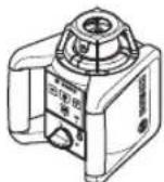
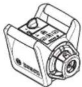
TOpN3OHTaIbHe NOnoKeHHA BepTNKaIbHe NOnoKeHHBCTaHOBIT BmIPIOBaHbHI pINaJy TOpN3OHTaIbHOMy a6o BepTNKaIbHOMy NOnoKeHHi Ha CTInKy OCHOBy, MOHTyIte Ioro HA WtTaHBI (38) a6o Ha HactIHOMy KpInnEHHI (42) 3 npNCPOcM DnR BnPIBHIOBaHHA.
Yepe3 BnCOky TouHcTb HIEJIIOBaHHB BMIpIOBaIbHn npnaI dyKye UyTNBO peary Ha CTpcaHH Ta 3mIH B noJoxHeHI. Tomy cnIKyTe 3a CTabINbHM nOJOKeHHM BmIPIOBaIbHO npnaIady, uO6 yHKNHYt nepepIBaHH y pOboti 3 npuHn DOdaTKOBOro HIEJIIOBAHH.
YbIMKHeHHBMMKHeHH
Uo6 yBIMKHyTN BmIPBOaHbHH INCTpyMeHT, HATNCHTbHa
BmHKaay (4).Yci iHnkaui KOPOTKOVACHO NIDCBiuyTbcra.
BmIPBOaHbHH INCTpyMeHT BNpOMIHoe 3MIHHN
na3epHH nPOMIHb (6) iTOky BnCKa, CNpAMOBaHy
Bropy (9), 3 BnIXiHNx OTBopIB (8).
He cnpaMOByTe na3epHn npOMInb Ha IIOJe i TBapHH i He nBIBtbc y na3epHn npOMInb, BKIOUaIOuH i 3 BeINKoi BIDcTahi.
BmipobalbHH IHCTpMeHT BiPa3y NouHae ABToMaTHHe HibenOBaHH. Pidac HbeNIOBHa HINKaTOp CTAHy (3) 6nMae 3eneHM, na3ep He o6epTaTcBcTa bNMaE. BmipobalbHH IHCTpMeHT BpuIBHnn, loHO INDKaTOp CTAHy (3) NOHAA CBITITCA 3eneHMM, a na3ep 6e3nepePBHO CBITbC. Picra 3abepeH HIBENOBAH HBMIPoBAH HINCTpMeHT ATOMaTHUHO 3anyckaTbC y potaunHomy peKMI.
He 3aHnWaiTe yBIMKHyTNI BmIPIOBaIbHH IHCTpyMeHT 6e3 dorgy, nCIA 3aKiHueHH pO60TH BmHKaIte BmIPIOBaIbHH IHCTpyMeHT. IHIi Oc6N MoKyTB 6yTH 3acinInneI na3epHM nPomeHem.
Bn MoKeTe BCTaHOBNTHpo6OuHpeKmBxBe BnpOeci HIBeIOBaHH KONKOIO potauiHoro peKmMy (5) a6o KHONKOIO NIIHORO peKmY (11).YcbOMy pa3I BMIPoBAhN IHcTpyMeHT 3aNyckaETbC8B ObpaHOMy peKmPi PO60THnicra3aBepWeHH HIBeIOBaHH.
Uo6BnMKNHYTN BmipOBaBHN IHCTpyMeH,ue pa3 HATNCHTb HA BMNKaU (4).
ДяЗхCTуБатApENoK a60akymyTOpIB BmIpOBAhHn IHCTpyMeHT aBTOMaTHUHO BmHKaETbCra, kIIO bIH BnIoo 3a donyctmIMeKxi cAmOHBeNIOBAAHH6iNbHIX Ha 2 roD. aboЯкso nOpepeKeHHn pO cTpyc cnpaucBOBye npOTAROM 6iNbwe 2 roD.BcTaHOBIb BmIPOBAhHn IHCTpyMeH I 3HOby yBIMKHITb NOrO.
Pekmm po60TH
OrnpexMIBpo60n
Yci 3 peKMM pO60TH MOKINBI y ROpHOTaNbHOMy i BepTKaNbHOMy NIOXKeHHI BmIPIOBaNbHOrO IHCTpyMeHTa.
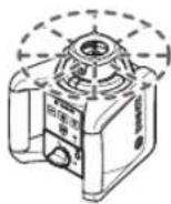
PotauiHHn pejHm
PotauiHH peKMMOCOBHBOpeKOMeHdyETbCry y pa3i BnKOpNCTaHHna3epHOrO npHMaaya.MoKaHa BnBnpaTniPi3Hi WBnKocTi o6eptaHH.
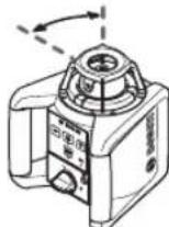
LiiHHH pexHM
UcbypeKmipo60tn3mHHn
la3epHnnPpomHb pyxaeTbcB
OBMeKeHOMy KyTI OTbOpy.3aBdAK
cbomy na3epHnn npomHb BnHO Kpaue,
HXBpoatauiHOMy peKmMi.MoKnBi
pi3HIkyTNPO3kPNTT.
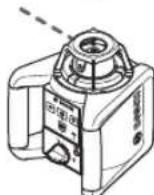
ToUKOBH pexHM
ycbomypekmi p60ntdoaTbcaHaikpaa BnIMicTb3mHOro naepHoro npomeHa.Bin npn3haeHHI npoctoro nepeheceHHBcOTn a60 nepeBipKn ToOK 36iry.
IiHn i ToKOBn peXmH He np3HaueHi npo60n 3 na3epHM npHMaem (36).

PotaizHmpeKHM
Iicra yBIMKHeHH BHMipOBaIbHn IHCTpyMeHT 3hAxOHTbcB B potauiHomy peXnMI 3i CTaHapTHIO WBNkICTHO o6eTaHHA (300 XB.1).
Uo6 nepeHn 3 niiHoro B poataiHn peXm,HaTNCHtB KONky poataiHoro peXmy (5) a60 KONky poataiHoro peXmy (26) Ha nybTi dIcTaHoiHO ynpaBnHna.
Uo3mHn WbNkictb oepTaHH, deKinbka pa3iB HaTNCaHTe H KaONy poTuHoro peKIMy (5) a60 KONky potauHoro peKIMy (26)HaNyblTi nctaHuiHoro KepyBaHH, NOKn He 6ye DoCAYHyTA nOpi6Ha WbNkictb. Ppno6oTox 3 na3epHm npHmayem peKomeHdyctb CbtaHOBIOBATHMakCMMaIbHy WbNkictb oepTaHH. y pao
po6it 6e3 na3epHoro dna KpaOoi BnuMnOcTI npHmaua na3epHoro IpOMeHn 3MeHnTe WbNkICt b o6eTahnn i 3acTOCOByte OkyIpyn dna p0oTH 3 na3epom (46).

JIiHHH pexHM/ToQKOBHH pexHM
Iio6 nepeHn y niiHn a6o ToKOBn peKm,HaTCHiTB KhoNky nHHoro peKmMy (11) a6o KhoNky nHHoro peKmMy (27) Ha nybTi dntaHuiHO r npabHnra. BImipOBAhBn IHcTpMeH NTpeMnKaeTbcra B liHn H peKm 3 NaMeHWM KyTom po3kPHTT.
Lio6 3mHnKyt po3kptTBAeKINbKa pa3iBHaTnCKaTe Ha KONky nIHInHO rpeXmmy (11) a60 KONky nIHInHO rpeXmmy (27) Ha npbTi nCTaHcuiHoro KepyBaHH, nOKn Ha dncnneI He bIDobpa3ntbcr NoPi6Hnn peXmpo6tN. Kyt po3kPHTB 36inbWyeTbCra NOEtAnHO 3 KOxHM HAtnCKaHHAM, B ToJ Xe Yac WnDkICTB oepTaHH 36inbWyeTbCra 3 KOxHM eTanOM.
Nicra doCRAHHeHHMAKCHMaJIbHOrO KyTa po3KpTTT BIMIPIOBaIbHIn IHCTpyMeHT npExoDITb B TOUKOHN peXHM nicra KOpOTKIiBipaui. NOBTOpe HATNCKaHH KONIKNIHIHO rpeXmY (11) NOBepTaIC IHCTpyMeHT B NIHIHN peXMM 3 HAmeHHM KYTOM po3KpTTT.
Bka3iBka:Yepe3IhePthictbna3epMOKe 3nerKa BHXoHnTH 3a KInuebi ToouKn na3epHoI liHii.
Функш

Tobopot nii/ToQnB rOpH3oHTaNbhe BnOuChi o6epTaHH (mB.MaA)
AkiuBmipOBAIbHn iHCTpyMeHT po3TaWOBAHn Ropn3oHTaIbHo,MOxHa po3TaWyBaTH na3epHy nIHIO a60 Na3epHy TOky B MeKax IIOUHNn ObepTaHHN na3epa. NOBOPOT MOxJIINBn Ha 360°
Дяцьо Вруну NOBepHitpoTauiHy roNIBKy (10)В
Heo6xide noNoxKeHHa 6O BnKOpHCTOByIte npblT
DuctanuHOrO KepyBaHHa: uOb NOBepHyTN 3a
rOdnHHNKOBoHO CTpIKIO, HATNCHTb KONKY «ПОБEPHyTN 3a
rOdnHHNKOBoHO CTpIKIO» (29) Ha npbTi nctauHIOHORO
KepyBaHHa, uOb NOBepHyTN pOtn T OdnHHNKOBoi CTpIKN,
HaNTCHITb KONKY «ПОБEPHyTN nPOTU rOdnHHNKOBoi
CTpIKN» (30) Ha npbTi nCTaHuaHOrO KepyBaHHa. Y
poTauiHOMy peKmI KNHKn He npaQIOYb.

IIOUHHa o6eTpAHnI np HBeptHKaIbHOMy i (DNB.Man.B)
YBepTHKaJIbHOMy nONOxKeHHI BIMIpIOBaJIbHOro IHCtpymeHTa Na3epHy TOUky, Na3epHy NIIIO A60 NIOUHy OBeptAHn DnI npocToI nepeBipKn ToOK 36iry a60 napaneBHOro BIPIBIOBAHHB DIANA3OHi ±8% MOXHa NOBepTaHn HABKOLO BepTHKaJIbHOi OCI.
Iio6 nobephytn 3a roHHNKOBOO ctpiKIO, HATNCHTb KhoNky IIOBepHytn 3a roHHNKOBOO ctpiKIOo (29)Ha nyNbTi nCTaHIO HORO KepyBaHH.
Iio6 nobephytn npotn rdoHHNKOBoi ctpiKN,HaTNCHTb KhoNky IIOBepHyTH npotn roHHNKOBoi ctpiKN》(30)Ha nyNbTi nctaunHoro kepyBaHHra.
ABTomatnuhe HIBENIOBAHHA
Orna
BmipIOBaIbHn IHcTpymeHT CaOCTiHo pO3nI3Hae roPOnTaIbHe a6o BePTKanBe nONoXeHH.ДЯ
nepexody mixrnp3oHTaBHHM iBepTKaBbHM
NIOXeHHAM BmHKHtB BMIPoBaHbHn IHCTpyMeHT,3HOBy po3aWyIte HOrO i3HOBy yBIMKHiTb HOrO.
Iicra yBIMKHeHH BmipIOBaIbHn IHCTpyMeHT nepeBipRe Irop3oHTaJIbHcTb Ta BePTHKaJIbHcTb NIOJOKeHH aBTOMaTHUHO KOMNeHCy HepIBHOCTI B MExax Diana3OHy cAMOHIBeJIIOBAHH np6n. ± 8% (± 4,6^)
Iiuc HibenboHnIHnkatOp cTHy (3) 6nMae 3eNeHHM, naep He o6epTaetbca Ta 6nMae.
BmipobalbHHn IHCTpymeHT BpiBHHn, IOHNO IHdkatop CTany (3) noHnae CBITNTCA 3eneHm, a naep 6e3nepepbHO Cbitnb. Picra 3abepeHn HibenobHHBmipobalbHHn IHCTpymeHT ABTomaTHo 3anyckaTbc y potauiHomy pexhmi.
AkiuBmipobanHnIHcTpymEtnicnyBIMKHeHHa60 nicra 3miHn noJooKeHHMaE yxHn 8%, HBeJIIOBaHH 6iNbwe hemoxnBE. Ybompyaipot3ynHcTBca,naep 6IImac,a IHnkatop Ctany (3) TpNBano CBITnbCra cepBOHM.
3aHOBOPO3aUyIeBIMIPBOaHbHINIHCTpyMeHTi 3aKeKaIte,POKHe3aKInHbCABOTMaTHuHE HIBeIOBaHH. Be3MHNIOXKeHHnaepABTOMaTHuHO BIDKNOHaCTbcYepe32XB,ABIMIPBOaHbHINIHCTpyMeHT— yepe32rOHNH.
HibenboBaHH BmipIOBaNbHn IHCTpyMeHT NoCTIH NOpeBipRc Ropn3OHTaBHe/BepTNKaIbHe noNOxKeHH. Pn 3MIHI NIOXKeHH aBTOMaTHHO BHKOHyETbC HIBeJIIOBaHH. Uo6 yNHNKHyT NOMINOK iN ac BVmipIOBaHH, potOp 3ynHReTcBc nI qac npoccy HIBeJIIOBaHH, na3ep 6nMa, a iHNkATOP cTAY (3) 6nMa e3eneHM.

Функци nonepeKeHHn npO CTpyc
Bmipobalhni iHctpymeHT o6nlaHnn fynkcioc nonepedkenn npo ctpcny. y paai 3miHn noIoojehn a60 ctpyc BmipobalbHorO iHctpymeHa a60 y paai bibpaii rpyHT BOHa nopepeJxye HIEJIIOBAHHy y 3MiHeHomy noloxheni, 3aBdAnKu Omy nopepeJxUToBcNOMNIKN uepe3cYB BMIPOBaBHorO iHctpymeHa.
YbIMKHeHHaAKTHBaIgnonepKeHHnpo cTpyc:
HATNCHTb KHONky nonepdkeHH npo ctpyc (2).IHINKAtOP
nonepdkeHH npo ctpyc (1)TPBnBAO CBITNbCA3eNEHM
KONbOpOM. nonepdkeHH npo ctpyc aKTHByETcbA
np6n3HO uepe3 30cekyndnicy yBMKeHHaYHKii
nonepdkeHH npo ctpyc.
CnpaobByBaHHn nonepdKeHHn npo ctpyc:AKUO
dian30H TOHOCI HIBeIOBAAHn nepeBnueHO npn 3MIH iNOXKeHH BmipOBaBHorO IHCTpyMeHTa a6o peecTpaii CnIbHOrO ydpA, cnpaBObyE nonepDkeHH npo CTpyc: oBeptAHn Ia3epa npnnHReTbCra, na3epHn npomihb 6nMaE, iNnKaTop cTahy (3) 3racaE, a INnKaTOp nopepKeHH npo cTpyc (1) 6nMa e YepBOHM. PtoouHH pexHM po60TH 36epiraTcbr.
PnB BMKHeHOMy nonepdKeHHI npo cTpyc HaTCHITb KHONKY nonepdKeHHI npo cTpyc (2)Ha BMIPKBaHbHOMy IHCTpymerti a60 KNONKY cKNaHnHA nonepdKeHHI npo cTpyc (28)Ha nyblTi dCtAHuHIHO KepyBaHHa.ФyHKua InonepdKeHHI npo cTpyc BMNKaETcb 3HOby, IBMIPKBaHbHIn HCTpymert 3anyCKaE HBeJIbOHaHH. LioHO BMIPKBaHbHIn IHCTpymert BnPiBHBcB (iINKaTO pTahy (3) noCTIH O CBiTbCB 3eJeHM), BIn ABTomATuHO 3anyKaETcb y 36peJekEHOMy peKMI.
Ipebeipte nnonkennnaepnor npomehno penehni Tooui 3a notpe6nckopnyte BnCOTy a6o opieHTaio BmipobalbHOrO IHCTpyMeHTA.
Ku npn cnpaoboybHni nonepexdkenH npo Ctpyc
fHKyI He 3aynckacTcBnOBtOpHM HaTnCKaHHM KHONK
nonepdkenH npo Ctpyc (2)Ha BmipBoaHOMy
IHCTpyMeHTi a60 KOnKn CKDaHHN nonepeDkeHH npo
ctpyc (28)Ha npblTi dntaHIO HOrO kepyBaHH, naep
ABTomatHNO BiKIIIOUaTbCrape3 2 XB,a BmipIOBaHNI
IHCTpyMeHT-ape3 2 roHNH.
BmKHeHHaYHKII nonepdKeHH npo cTpyc: OMH pa3 haHCHiB KhoNkY nonepdKeHH npo cTpyc (2) a60 dBiy i npi cnpaobByaHHi nonepdKeHH npo cTpyc (iHnKaTop nonepdKeHH npo cTpyc (1) bImae uepBOHM). JaKuo nonepdKeHH npo cTpyc BmKHeHO, iHnKaTop nonepdKeHH npo cTpyc 3raac.
Bka3iBka: 3a donomoroIpybTa nctahHIO KepyBaHHF yHKUIO nonepeJKeHHN pO CTpyc He MOKHa yBMKHTn abo BMMHyTH, a MOKHa nepe3aNyCTHTn TlBKn Nicra Cnpa2bOByBaHHA.
Ipebeipka Touhocti BmipobbHoro IHCTpymeHa
ФakToH, 0O BnNBAKt b Ha ToHicTh
HaibnBn BnNB CnpaBnE TemnepaTpy 3OBHbO cepeoBnua.Oc6nBO TemnepaTyPi nepenadi,IO cnoctepiraTObC B Mipy BiDaNHeHH BID rpyHTy,MOKytb CNPHNHTBjIXNHeHH Na3epHOro npMeH.
OckibkTNemnepaTyPi KONBaHHeHa6iNbHmN 6IIN3bKO
do rpyHTy, Heo6xIDHO NOUHAcOn 3 DOBXHNH
BIMIPOBaIBHOI iINHKN 20 M 3aBXn MOHTyBaTH
BIMIPOBaIBHn pInlaH Ha tATNI. Kpim TORO, 3a
MOXINBCTIO BIMIPOBaIBHn IHCTpyMeH Tpe6a
BCTAHOBIBaTH B CEHTPI PO6Ooi DINAHK.
BixnHeHHcTcHbNOMITHMmNOHnHaOHc3DOBKHN BmipOaBbHOiJINrAHHNpH6n.20M,HaBicTaHi100M BOHMOxTyCTaHOBTN yDbui a6o HABtBuETBepo 6Ibwe 3HaueHHH HIX npu 20 M.
Iopn i3 3OBHIMM yMOBAMn TaKoX i cneuifiuH dIy IHCPTymHTy MOBN (HaNP..CTpyCNABH ynap) Moxyt np3BOJNT Do BiXnNEb.3JIe pnuHH KOxHOpa3y nepeD NOaTOM po6OTn nepeBipraTe ToHicTB HBeIOBAHH.
IaKIO nIac OndHie3 nepeBipOK BmMIPOBaBbHIN IHCTpyMeHTnepeBnITb MaKcHMaJIbHO DoNcyTHe BIXxHHeHH, Ioro TpeBa BiHecTH Na pEmOHT Do MaIcTePHi Bosch.
IpebeBipKa TOHOCti HiBeJIIOBaHHa Y TOpH3OHTaIbHOMy noJoxeHHI
ДлготриманнHaHINORI tOHTHOro pezYbTaTy nepeBipKy peKOMeHdYcBaBKOHOyBaTH Ha BInbHi BmIpOBAhBiHдIHJIIOBxNHO 30MaMiChomy rpyHTI nepED CTiHO. ДлгКоЖиO 3 O6ox OceB bKOnaHTe NOBHy npoueDpy BmIpOBAHHA.
-MoHTyTe BmipOBAhHn IHCTpyMeHT y roH30HTaJIbHOMy NOnOKeHHi Ha BiCTaHI 30 M BiD CTINHa HTaTNIbI a6o NoCTaBTE Noro HA TBepdy pIBHy NOBepxHIO. YBIMKHITb BMIPOBAhHn IHCTpyMeHT.
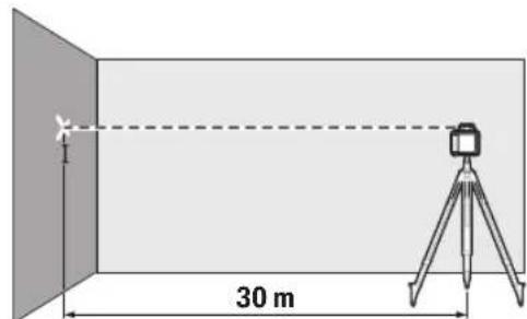
-πicnaBepweHHH hibenHOBaHHNo3haTe cepeny Hna3epHOrO npomeHa CTiHi (tokaI).
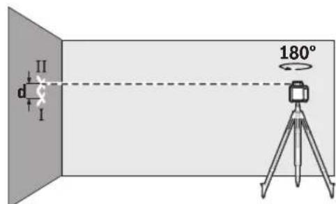
-NoBepHb BmipobalbHn IHcTpyment Ha 180°, He 3miHOuN HOrO NIOJKeHH. DaIte Homy HIBeHOBaTcA i No3Haute CEpeDnHy Na3epHoro npomeHa cTIHi (Toka II). CNIkyte 3a TIm, 06 TOka II 3haxoHnacr Akomora pibhiue Had a6o nI TOkO I.
P3Hnq d mix DBOMa NO3haeHmHa CTiHi TOkAmI I I -Ce qakTHUe BiXHNHeHHBIMipIOBaIbHOrO IHCTpyMeHTA NO BNCOTI DnBIMIpHOHOI OCI.
NobtopitbIpo npoeDpypIINHxOcE, 03aHHnHnCn.
IIraIbOro NOBepHtB BMIPHOBaHn IHCTpyMeHT nepei
NoaytKom BmipHOBaHH Ha 90^
HaDinH30 M MaKcHMaJIbHO DoNyCTHMe BiXnIeHHA CTaHOBHTb:
30 M × ±0,1 MM/M = ±3 MM. TaKHM YHOM, pI3HHU d MIX TOUkAMn I lll nd cac KOKHOi a6o o60 npOeDyP BmIPOBAHH MoKe CKJaTn MaKCMMyM 6 MM.
Bka3iBkn 0do po6oTu
Дллno3haeHn3aBxHn BnKOpHcToByte cepeDnHy na3epHOI TOuKn abo na3epHOi nii. Po3Mp na3epHOI TOuKn/na3epHOI nii 3MiHoEbC R B 3anExHocTi BiD BiCTaHi.
He 3aHypoTe BmipIOBaIbHn IHCTpyMeHT,3apHn npicptpi I nylt DCtAnuHOrO KepyBaHH y Body a60 iHsi piHH.
BHTnpaIte 3a6pydHeHHB OBOrOIO M'koIO raHcyIpKOIO.He BHKOpNCTOByTe KOHNX MNQUHx 3ac06iB a6o p03uHHNKIB.
3okpema,perynapno npouuauite Ha BmipobalbHomy IHCTpyMeHTI NOBepxHI KOHO BXiDHorO OTBOPy na3epa i cnkikyte npu cboMy 3a THM, uo6 He 3aIIhuano8 BOPCINOK.
Cepbic i koncynbtaqii 3 nHTaHb 3actocybaHHA
B cepbichi maiepHi Bn otPmaeTe BiNobib Ha BaWi 3aHTAHH CTOCBOH pemOHTy iTexHCHoro oCnyROBYAHH BaWOro npOkyT. ManIOHNB DetaIAX iHOFopMaio I Odo 3aYactHH MOKHa 3HaHTN 3a aApceoi: www.bosch-pt.com KomAnda cnIBPObitHKIB Bosch 3 hadaHH KOHCytai JIO DO BIKOPCTAHN npOdykii i3 3aIOBOJIeHHAM BIDNOBICTb Ha BaWi 3aHTAHH CTOCBOH HAIOT npOdykii Ta npINaI daNo Hei.
PnB BCix DoaTkoBHX 3aHHTAHX Ta 3aMOBneHHI 3aHactNH, 6yNb lacka, 3a3Naayte 10-3NaHnn HOpep dna 3aMOBneHHN, 90 cToITb Ha nacnpTHI TabnHpI npOdyKty. IapaHTiHe oCnyROByBaHH i peMOHT eJeKTPoIHCTpyMeHTy 3diChHObTCBc BIDNOBIDHO IO BmOr i HopM BnTOBOJIIOBaHa TepntopBcIX KpaIH NHe u y fipMOBnx abo ABTOPIN3OBaHHx cepBichNX ueHTpax fipMN «Po6eTp BoU|. PIONEPJXHEHH! BnKOpNCtAHN KOHTpApaKaTHoi npOkyu He6e3Neue H E KcNpyaTaui i MoKe MaTH HeaTbHI HAcNiKn DnIzDopOB'BAroTOBNEHHI pO3NoBcKOJKeHHN KOHTpaKaTHOI npOdyKuII nepeciNyETCBs 3a3aKOHOM B aDMInICTpAIBHOMY i KPMInAHbHOMy NOPdKy.
ykpaiHa
Bou CepBicHH NcHTp eNkTpoIHCTpyMeHtIB Byn. KpaHr 1
02660KmB60
Ten.: +380 44 490 2407
ΦaKc: +380 44 512 0591
E-Mail: pt-service@ua.bosch.com
www.bosch-professional.com/ua/uk
Aapeca PeriohaIbHnX rapaHTiINHx cepBicHnx MaIcTepeHb 3a-3naeHa B HaioiaHbHomy rapaHTiHomy TaIOHi.
Adepeinihnx cepbichnx ceHTpIB HabeDeHO HnXHe:
www.bosch-pt.com/serviceaddresses
Ytunizaia

EneKtpoiHcTpymEnTH,akymyIaTOpN/6aTeapei, npnaI ynakOBky Tpe6a3aBaTH Ha ekonoruHNo uChTy NobTophNy nepeop6ky.

He BnKnJaTne eneKtpoiHcTpymEnTa akyMnyTopn/6aTapeB NoobyToBe cMTTA!
IIneIgKpaH EC:
BIDIOIHO IO EBPoneCboKoi INpeKTHBN 2012/19/EU
eNEKTOIHCPTyMeHTN,IO BNIuINi3 BxNBaHHa,Ta
BIIOIHOIO EBPoneCboKoi INpeKTHBN 2006/66/EC
NoIKoJKeHl aO bIO BnpaocBoHai akMyTOnpHi 6aTeapei/
6aTaepKN NOBHNNI 3DaBaTnc OKPemIoYTHNI3yBatncra
ekoIOrHNO CHTm CNOC6OM.
Ka3ak
Eypa3nna 3KoHOMnKaIbIK OdaftbHa (KeDen OdaftbHa) Mywe MemNeKeTtep aymafbIHda KOnDaHbIaNbl
HdiPywihin OHIM yiwin Kapactbipfah naaanahy KxKaTapbHbN KypambHa naaIanaHy XeHHeiOCbl HcKaynbK,cohBmeh bipre KocbMwnap da bony MykH.
CnKeckiKti pactayKaHbIaknapaT KocbIMwda 6ap.
EHIMdi eHdipreH MemNekeT TypaIbAknapaT eHimHi
kopnycbIHDa kHe KOcBIMwada KepeTinreH.
EHdpireH Me3iHyckaybIK Myka6abHbIH COFB6eIHDe XHe OHIM KOpnycbHda KepeTirreH.
HmnpTepreKaTbIcTb6aNnHaBcaknapaTeHIM KaTAmacbHdKepcetinreH.
HIMPi naiDnany Mep3iMi
HMHHHKb3MeTetyMep3iM7KbIn.0HdipinreHmep3imHe
6actan(0HdpykyHi3aybITakTaWacbHdaJaa3bInraH)
ICTeNe5KbINCaKaTaFAHHaCOH,0HIMDiTEKcepyci3
(cepBnCTIKTeKcepy)nainaanyCbHbImaIbI.
Kb3METKeHemepe naDanaanyuHBnKatenikTepi MeiTe HbIFy ce6entepinH t3imi
-0HIM KOpnycbHaH TIKeNeI TYTI H WbIcKa, NaJaDaNaH6aHbI3
JkaybiH-1aawbHKe3iHDe c6bPTTa(daIada) naDanaH6baH3
- Kopnyc iwihe cy Kipce Kypbifhbl Kocybl 60Maht3
Uekri Kny Genrinepi
-0HIM KOpNcBbH3aKbIMdanybl
Kb3met Kepcety Tpyi MeH xiniri
OpaHanaHanCOEHHiTa3aaycbHbnaBbl.
CaKray
KpyraKkepe daKaTay Kepek
KorapbI TemnepaTypa Ke3iHEn KHe KHy CaynepePiHi, acepiHEn anblc caTay KepeK
- cakay Ke3iHne TemnepaTypaHbIH KeHET aybitKybiHaH KOpFay KepeK
-erep Kpyan Jxymcak Cmke HEmec nlaactNK KeiCTe XeTKi3iJnce OHbOcbE3IHKOPFaBbIa Ka6bHda caTay YCbHbIaNabI
- cakay waprtapbI typabIKocbIMwa aknapaTanyuH MEMCT 15150 (Wapr 1) KxkaTbIH kapaHb3
Tacbimanday
TacbImaIay KeiHne OHIMJI KynATyraKeKe KeKenre HmexAHKnBk bknan etye KaTah TblbM CaBHaDbl
-6ocaty/xykTey Ke3iHne NaekTI KbICaTBH MaunHaapn naDanahyFa pyKcat bepinmeNi.
-tacbimaywaprtapbltanantapbH MEMCT 15150 (5 wapt) KxKAtbH OkbHb3.
Potaunbik na3epre Xhe KaushbIKtah 6ackapy KypanbHa apHanfah Kayinci3dk TexHnKacbIHbIH HycKaynapbl

Kayinci3 xhe cehimdi xymbc ic tcy yuih 6apnbik hycaynbikTapdbI OKbIn opbHday Kepek. BepinreH hcyckaynap opbHdAnMaHan XaJda, kipiktipinreKopraHbic
KypbIbnapbHaTepecepEtinyi MyMKH.EcKepy TaKaTnAnapbH eW KaFdaNda OKbIMaTbH KyRe XeTKi36eH3.OCbI HYCKAYAPDbI CAKTAN KOHB13 XHE OHIMI BACKAIPFA TAbIC ETKEHDE KOCA BEPIH3.
A6ai 60nbHb3 -erep ocby xepde 6epinre naiDanany Hemece ty3ety Kypanapabihn 6acKa Kypanlanh naDanaHan C Hemece 6acka Jxmbic 6tipei opbHanca 6yn kaynti caynere wanbHyra anbin Kenyi MymkIn.
Onwey KypanbI na3ep ecepy TaKtacbIme 6ipre Xetki3inei (rpaФнka 6etihderi onwey KypanbHbIn Cperinhe 6enrineHren).
Erepnaepeckpy TaKtacbHbMmTHi eniizdiin 6ypbH OHbOpbHa eniizdiHtinHderi XancbipMaHbXa6bictbpiHb3.
Panaep KypbInfbcblHa eukHdae3repty opbIHMaHbI3.
- Na3ep Kepy Ke3inDipirih (KepeK-japaK) KopraHbI W Ke3inDipiri peTHe naaanah6aHbI. Na3ep Kepy Ke3inDipiri na3ep cayneCin JaaKcbiPak Kepy yuHn KOJaHaBnAaBbl, aanaJda na3ep cayneCineH KopraMaHbl.
P3ep Kepy Ke3inipirih (Kepek-kaak) Kynne H KopraTbH Ke3inipik petiHne Hemece kon Ko3faNbcbHda naaDanaH6anb13. P3ep Kepy Ke3inipiri ynbtpaKynriH caynepen ToIbIK KopFaHbCTb KaMTaMaCbI eTneNj XHe TycTi ce3y KaBineH a3aTaNb.
O himTeK 6iikTI MaHaFA XaHe TynHcyKa 60nIKTePmeH XoHdeyre pyKcat etiH3.ObnaaKayinc3dIKTH CaTanybHa Kenin bepinei.
Banap naep enwey kypanbH 6akbnaycb3 naindaHa6acbH. Onap 6inmeaamdapdbH Ke3IH WAsFbIbCTbpy MymKIn.
Kahfbw cybIKtBtKTap,ra3ap Hemece wan 6oNaTbH Jkapblbc Kayni 6ap optada Kymbic icTeMei3. YuKbH naDa 6oBnI, WAnDbI HeMece 6yDby TyaHaDbipBy MyMKH.
KocbIMwa Kayinci3ik TexHHKaCbIHbH Hyckaynapbl GRL 250 HV:

Ja3ep caynein adamapfa Hemece Kahyapnapfa 6abftTamaHbI 3KHe 8iH3 de ticene Hemece wafbnbckAn na3ep Ceyncine KapaMaHbI. Byn aadmpdbH Ke3IH WafblDpyb MyMKH, cTcI3 OKfanaPFA kenyi Hemece Ke3re 3akbIM KeTtipy MmKIN.
ErepnaepcayneciKe3reTycceKe3depjxymbIn 6actbcaynede npabkapatykepKocbIMwaKayinci3ikTexHHKaBHBHvckaynapbl GRL300HV,GRL300HVG:
Θnwey KypabHdaFbI na3ep WbIFapy cahbinaynapbi ecepeTy taKaTaiuacbImen BenrineHren. Onwey KypabH nainanahFaH Ke3eO npabH KyiHe Ha3ap aydapbHb3.
ErepTnicti ecepy TaKraaAscbHbH MaTini eniH3dIn TiniHc6oNMaCa, anFaw pet naDanahydAn 6ypbH OHbH opHbHa eniH3di TiniHderi XancbipMaHbI Xa6bictbPbHb3.
3R na3ep cbHb6bHdaFb na3epdi naDanahya MemnekeTik 3aHapdbEcEepiiz. Con 3aHapdbe ecepeMeCTIK JapaKaTaHaynapFa anbl Kenyi MymKIn.
OJnuey KypanbH TeK na3ep acnantapBn naDanahyb6inTeH aamap naDanahybMyMKIn. EN 60825-1 6oBihua 6yn na3epiH Ke3 6en Dehere 6noTnBik ecepixhe KayinTpdi 6onblpMay yuHn na3ep KoprabyH Dpybc naiDanaHy tpaBb 6inImepdi da KaMTnbl.
Thicti naepe cckepTy taKanapbimEn onwey KypanbHn naDanahy aHaMfbH 6enrineH3. Ocbnai bEge daamap Kayiniti aMaKaTa TpybHa kon 6epMeci3.
Θnwey KypanbH 6ege aamap kipe anatbH Kaanapda KaandbipMaNb3. Onwey KypanbH naaanaHydb 6inmereh aamap 6eepi Meh 6ackanapdbj JapaKaattaybl MyMKIn.

Ja3ep caynein aamapra Hemece
Kanyapnapa 6aftTamaHb3 KHe e3iH3
de na3ep cayneine KapamaHb3. Byn enwey
Kypanb EN 60825-1 6oBbHwa 3R na3ep
KnacbndfaI na3ep cayneepin WbIFapabbl.
Ja3ep cayncie y3ak KaWbIKtBkTah da Tikee
kapay Ke3re 3aKbIM KeNTipyMymKiH.
PaepeepnemcayenehyaMafbHbH6akbinaHyiba HemeceTacanaHybHaKe3XeKtki3i3. Naep cayenepeinih6akbinaHbTHaMaKaTpaRaWeKtey 60rde aamapdbH Ke3dpeHHaKbIMDaHybHbH anDbH anaDbI.
Onwey KypanbIn naep caynenepi Ke3 deHreinHen ToMeH eTeiH etin opHaBbIb3. OcbnaKe3 3aKbIMaHybHa Kon6epeMeci3.
21|Ka3aK
Tepe3e Hemece aHa cHKTb teric 6etTepdhena3ep cayneciin KaTapbIybiHa XoN 6epMehi3.
KaIapbIraH naep caynei da Ke3re 3nHdbI bonybl MymkiH.
KocbIMwaKayinci3ikTexHnKaCbHbH Hyckaynapbl
CayeneHy Ke3iH Kepy yiwih Dyp6i Hemece nyna CnKtbl eikahdONTHKaIbIK XHHaFbI W KypanDapBn NaDanaHa6aHbI. Onap Ke3iH3re 3akbIM KeTtipyi MYMKIH.

MarHHTTIK KepeK-kaPaKaTapdbI HmnnnHaTtAaTapdbH KHe
KapnoctMnynTop HemeccnHcynnn COfbcblcnkTb6acka da MeuHaHaBik KypflfblnapdbHkaHbHa KoMaHbI3.
KepeK-kaapakTapdbH MaHHTepi
HMnHaHTaTAPdbH HemeCe MeuHaNbIK
KpybIaNpabH XyMbICbHa acep etetih epic
Tybpapbl.
MarHHTI akceccyapbl MaHHTI depek TacbMaIaywblnap MeH MaHHTke ceImtan acnantapHa anbc yctAh. Akceccyapnap MarHHTepiH acepi KaNbHa KeTipyre 60MaHtBHe DepeKTeP XofanybHa anbl KEnyi MymKiH.
AkkymyIaTOpnapbI HeMece 6aTapeanapdbiaaHaB13.KbIcKa TynbIKrany Kayni 6ap.
AkkymyTOp 3aKbIMdaNfAH Hemece dypbc naiDanaHbIMmaH KaFdJa, OaH 6y bIByM yMKiH. AkkymyTOp XaHbIN Hemece XapbIn ManyBIMyMKiH. Ta3a aya iWKe TapTBH3 JxHe waBIMap 60nca,ApirepHiK Kemerine KyrHin3.By TbHbC any KonDaPbIH TitIPKeHdpYi yMKiH.
AkkymyIaTOp dypbc naiDanaHbIMarHaH HeMece 3aKbIMaIaNFaH KaFdaJa, AkkymyIaTOpdHaCybIKtbIK arybl MyMKIn. OFAH THMeH3. Ke3neCOK Tepire THReHc, con Xepdi CymeH WauBbHb3. CybIKTBIK Ke3re THce, MeHNuHaNbIK KMeK aJIbHb3.
AkkymyIATOpdaBfI cyIbIKTBK TepiHITtIPKeHdipyI Hemece KIpyIMMKIH.
Were Hemece 6bybI chnKtbl yTbI 3aTTap Hemece cbiptkI acep apKblnI aKKMyynIaTOp 3aKbIMdaHybl MYMKH. By KlcA TynBtanyFa anbn Kenin, aKKMyJrTOp Kahybl, TyTH WbIFapBy, KapbinyI Hemece Kb3bn KeTyI MYMKH.
PaiDanaHbImaTbH AkkymnTopDb TYicnepdi TybIKayi MymKIN KbICTbIPfBHTapDaH, TbHdapHaN, KITTEpDeH, WERenepDen, BHTTepDen XeHe 6acka Ycak Temip 3aTTapDaH cKaTaHbI3.
AkkymyIaTOpTyicnenepiHInapcbiHaDaBklicKa TybikTany KyikTepe Hemece optKe Akenyi MymkiH.
Bosch akkymnytOpbHn TEK eHdpuyi YcbiHrae HImpe naIaIaNbHbI3. OcbnaIaFaHa akkymnyTOp kayintI apTBk KxyKTeMeHeKopFaIaI
Bosch akymyntopbih tek kunhaKaTfbl 3apdTaftbiu Kypbnfbimeh 3apdTaHbI3.
AkkymyITopnpapbljXbinydah,cohdai-ak,MbIcIbI,y3diKci3 KYH XapblHaH,OTaH,KipdeH,cydaH XHe bINFaIaN KopFaHbI3.
KapbIbIC KHe KbIcKa TyblkTany Kayni TyblDaaibl.
3apayay Kypanapby ywiin Kayinci3dk HycKaynbikTapbi

BapnbkKayincdik HcckaynbkTapbH
KHe eceptnenepe0kbHb3.TexHKaibk
Kayincdik HcyckaynbkTapbH XHe
eceptnenepeCaKaTaMay TOKbH COYbHa,opt
KHe/Hemece aybip kapaKaTTaHynapra anbIN KenyIMMKH.
Bonawak KymbIcTAP yuH Kayinci3ik HcyckaynbIKTapbl
MeH eKeptnenepeCaTAN KObIHbI3.
By 3apTay Kypanbl
6anaapdbiH, DeHe Hemece OJ Ka6ineTepi WeKTeIReH,
TaXnpi6eci XaHe 6ilimi a3
aAaMdaPbIH NaJaDalaHybHa
apHaMaFaH. OcbI 3apTay
KypaBImeH 8 JxactAH acKaH
6anaapdbIH XaHe DeHe, ceIm,
OInay Ka6ineTepi WeKTeIReH He
Taxipnbeci MeH 6ilimi a3
aAaMdaPbIH KyuHcI Kayinci3
NaJaDalaHy TpyaBl HyCKaycbI3
XaHe KaYaantbl aAdAMhbH
6akblaybHCbI3 NaJaDalaHybl aca
Kayinti. Kepi KaFdaJa dYpbic
naJaDalaHbay XaHe JapaKaTTaHynap
Kayni naDa 6olaBl.
PnIaIaNHy, Ta3aIay XeHe Kbl3MeT KOpCey Ke3InDe 6anapFa MyKnT 60nbHb3. BanaIapDbH 3apIaTay KypalbIMeH OHaMaybHa K03 JKeTKi3iHi3.
Tek Bosch NiCd/NiMH aKKymyIaTOPnapbIH (KyaTTbINbIFbl 9A-car (2 aKKymyIaTOP yawbIFbl) KypaHTbIH) 3apAdTaHbI3.
AkkymyITop Kepheyi
3apraTafblk KypblfHbIH
aKKymyIaTOpbl 3aprTaay
Kepheyine caikec kenyi kaxet. KaTb 3aprtanMaTbIH
aKKymyIaTOpnapbl
3apraTamhbl3.Kepi JkaFdaJa ept
HeMece Xapblny Kayni naJa
6oIaBl.

3apTay KypaBIn XaHbipdAn Hemece
binFaIbIKTaH KopFaHbI3. 3JnKtp KypaIbHbI iWHe cy Kipce, on 3JnKtp TOfbHbIH COFy KayniH apTbIpaIbI.
Oneey KypanbIH TeK XHHaKTarbl 3apnTay KypanbIMeH 3apTaHbI3.
3apnay KypanbH Ta3a yctahbl. KypanbH nactaHybl TOK COYbyi KayinIH TybiHaTaB1.
Op naDanaHydAn anbH 3apdTay KypaBnH, Ka6enbdi Xhe aHbpTeKcepiH3. Akaydbi 6aikacah3 3apdTay KypaBnH naDanaHaBt3. 3apTay KypaBnH 03iH3 aWnabH3, OHb TEK 6iniKTi MAmAHFa XHe TynHcyKaBn6IWeKtePmeH XoHdeti3. 3aKbIMDaFAn 3apdTay KypaBn, Ka6enb XHe aHbp 3neKtp TOfbHbN CORY KayinapTTbpaBn.
3apntay KypalbH Kocynbl Kynde OHaJXHaTbH 6ETepDIn (Mbicanbl, KaFa3, Mata XaHe T.6.) YCTIe KOImaHbI3 Hemece XaHbI3aTTapdbH XaHbIHda naIanaHbA13.3apTAY Ke3iHne 3apTay KypalbHbH KbIaby Ce6beHEn ept Kayni naJa bOanbl.
ΘHIM XΘHe KyaT CnnaTTamacbl
Pnndanhy HcckaynbfbHbH anFB6nirHcypeTepin ecepiia.
TaFaiBihany60bHwaKoJdany
Potaunlbyk,na3ep
Onwey KpaanbI dAn KeIeHn, TIK cb3bKTapdbI, HbcHaHanay cb3bKTapbMeH nepneHnkyIpy HkyTepepi enweye XeHe TeKcepye apHaHaH.
Onuey Kpyanbi iwiKMeH cbiptkbi aMakTapda naJaIaHaFapHaIraH.
KaawbikTan 6ackapy Kypanbl
Kaabtkanbackapky KypaBis Bosch potaunbik naepnepin HdpkaB3bn cayne apkblb backapyfa apHaHFaH.
KaabkTah backapny nIbTi iIte XaHe cbiptTa naJaIaNHaHyra KapaMdbI.
Kopceinren Kypamdb6nwekterp
KopceTinreH Kypamac 6oIeKTepeHHemipnei rpaKaanb6etepneri enwey KypanbMeH KaBkTaH 6ackapy KypanbHbH Kcpctinime Heir3dJeRr.
Potaunnbnnaep/3apraTarlkynpblnFbI
(1) CoKbI TypaIbI eCKeTp yHKUcBHBH HNINKaTOpbl
(2) CoKkbl TpyaIbI eckpTy Tymeci
(3)KyHnHnKaTOpbl
(4)Kocy/ewipy Tymmeci
(5)PotaunnybikpezmTymMeci
(6) AINbIMaJIbI na3ep cayneci
(7)KaawbiktanBackapyDatnir
(8) Na3ep caynecihiu bifbcacbblnyb
(9)KofapbI KapaTbINFaH nepneHnkyIpaTa6aHbI
(10)PotaunlaBik6bAteK
(11) Cb3bIKtbIKpeKHM TYMeci
(12)Батуарег Туразлы eckeрту
(13) AKKymyIaTOp
(14)Батаразбенimi
(15)BaTapeB6enimHHbCbipMacbi
(16) Akkymyntop bicbipmacbi
(17)3aayy
(18)3aPraTafblI KypblfB
(19)3apraTafbI KpybInfbHbHkeniik aawacbi
(20) 3apraay uTekepi
(21)UItaTbB6ekitkiu,5/8JIOHM
(22) CepnIbIK Hemip
(23) La3ep eckepy TaKtaebi
(24) Μαερ υβίγρу cahβnaybβhν εκερτγ τακταβγ (GRL 300 HV/GRL 300 HVG)
A) BeHeneHEn HEmec He ChnTaTaNfHan Ka6bIbKTap cTaNdaptTbI XeKti3y KENEMiMeH KAmTbImaN ToBikKa6bIbKTapdb 6iDIn Ka6bIbKap6afDappamAmMbI3anDaTabcIb.
Kaawbiktan 6ackapy Kypanbl
(25) Kaawbiktah 6ackapy kypanbl
(26) PoTaunJIbIK peXmM TymMeci
(27) Cb3bIKTBkpeXHM TmMeCi
(28) CoKbI TypaJIbI eKeptydi 6actanKbI KyIe KaIapy TyImeci
(29) Cafat TiniHin 6aBfItbImeH 6pyay TyImeci
(30) Cafat TiniHb6afBtBHa Kapcb6ypay TyMeci
(31) CtrHan XjIepy HnDnKaTOpbl
(32) INφρaKaBbIn cayne mbfapy caHbInayb
(33) CepnaybIK Hemip
(34) BaTapeB6eimikKaKNaFbHbHb6ekiTkiU
(35) BaTapee 6enimHin KaKnaFb
214|Ka3aKa
KepeK-kaPakap/Kocankb6nweKTeP
(36) Na3ep Ka6bIaBfA1bIb
(37) Θλωειμ πεηκα
(38)UHTaTHB
(39) Ka6bipra 6ekitkiinH 6ekitkiu 6ypaHdacbi
(40) Ka6bipfa 6ekiTkiuHIN 6ekiTkiu caHbInaynpa
(41) Ka6bipfA 6eKITKIiHIN 5/8IHOHMIDIK WTAINB 6eKITKiU(A)
(42) Ka6bɪpfra 6ekɪtkiwi/Typanay 6nərbi
(43) Typanay 6bnorbHnDaBb 6pyaHa
(44) Ka6bipf6eKtkiHinH 5/8IOHMdk 6ypaHdacbi
(45) MaHnHT
(46) Πa3ep Kεργ Κεiδπiρi
(47) Na3ep HbicaHbik TaKTabc
(48) Ⅲa6aadaH
A)BeHHeneHHeHemece CnTTaTaN HKa6bIKTap cTaHApTTbI XeKti3y KENEMiHcKaMTbIMMaBb. ToNtikKa6bIKTapDbI 6iDIn Ka6bIKTap SaFapNaMmBa3dAn Ta6acbl3.
TexHnKanbIK mAnimetTep
| Potaunnyknaepr GRL 250 HV GRL 300 HV GRL 300 HVG |
| Оним Немрí | 3601K616..3601K615..3601K617.. |
| Жуmbіс aimaftы (radnyc)A(B) | | | |
| - nazer каблдагышьсьsham. 30 m 30 m 50 m | | | |
| - nazer каблдагышьimeh sham. 0,5-125 m 0,5-150 m 0,5-150 m | | | |
| Hивелерney далдг(A(C) | ±3MM (30m
шамасьнда) | ±3MM (30M
шамасьнда) | ±3MM (30M
шамасьнда) |
| эдetteri озdirigenн Иивелерney диапазоны ±8% (±4,6°) ±8% (±4,6°) | | | |
| эдetteri Иивелерney уak'tы 15 c 15 c 15 c | | | |
| Айнany жыдамыгы 150/300/600 ман | -1 | 150/300/600 ман-1 | 150/300/600 ман-1 |
| Сыздык ржим徴у санылay бчыshi 10/25/50° 10/25/50° 10/25/50° | | | |
| Жуmbіс Temperatypacсы -10°C ... +50°C | -10°C ... +50°C | 0°C ... +40°C | |
| Сатуг Temperatypacсы | -20°C ... +70°C | -20°C ... +70°C | -20°C ... +70°C |
| Herizriбийский устенье макс. падалану等相关 | | 2000 M | 2000 M |
| Салыстормны aya bilingdiblbyfbl, макс. | 90% | 90% | 90% |
| Постану дөрөсeci IEC 61010-1 сандарты | | 2(D) | 2(D) |
| Боьынша | | | 2(D) |
| Лазер класы | 2 | 3R | 3R |
| Лазер турì | 635 hm, < 1 MBT | 635 hm, < 5 MBT | 532 hm, < 5 MBT |
| Альперmaшынь | 0,4 мраз (тOLьК
Бчыш) | 0,4 мраз (тOLьК
Бчыш) | 0,4 мраз (тOLьК
Бчыш) |
| Кendенецштатов bekitkiш | 5/8"-11 | 5/8"-11 | 5/8"-11 |
| Аkkуmsлартогпap (NiMH) | 2 × 1,2 B HR20 (D)
(9 A-car) | 2 × 1,2 B HR20 (D)
(9 A-car) | 2 × 1,2 B HR20 (D)
(9 A-car) |
| Батерлар (сintini марганец) | 2 × 1,5 B LR20 (D) | 2 × 1,5 B LR20 (D) | 2 × 1,5 B LR20 (D) |
| СалмавіЕ PENTA-Procedure 01:2014 Кужатынcaш 1,8 кг | 1,8 кг | 1,8 кг | |
| Флишев dipevi (усындьгы × ehi × biktiri) | 190 × 180 × 170 MM | 190 × 180 × 170 MM | 190 × 180 × 170 MM |
| Корганьс дөрөсci | IP 54 (шан мени
шашьогды сүдан
Коргалдан) | IP 54 (шан мени
шашьогды сүдан
Коргалдан) | IP 54 (шан мени
шашьогды сүдан
Коргалдан) |
A) 25^ C
B) Kymbc aimafbH Konacb3 Kopay wapTapbHa (Mbicanb Tikeen Kyh cayenepeiHe) KbickapTy MmKIn.
C)0cb6oBbIMeH
D) TeK KaHa ToK eTkI36eHIn hac naJa 60nabdi, bipak Kei6ip kajda napda epy HtNHexciHte ToE tki3y kaIneri Taia da 60nyky Tytinei.
Onwey KpaBbHb3aybTTbK TaTaNaaFb Cepnblk Hempi (22) OHbl dypbic aHbIKTaYfKa KEMKTecdi.
| Зарадагык курbingы CHNM1 |
| Өнöm hämipi | 2610 A15 290 |
| Кирс керney B~ 100-240 | |
| Кирс aiиьмалы тok киiniri Г 50/60 | |
| Шыfcьс керney B= 3 | |
| Шыfcьс тok A 1,0 | |
| Зарадаг Кезигдгі рүйсатетілген akкументор
temперауразы | °C 0 ... +40 |
| Зарадаг уakыты car 14 | |
| Аккументор уяшikтарын саны 2 | |
| Номиналы керney (ар akкументор уяшыгда) B= 1,2 | |
| Салмавы EPTA-Procedure 01:2014 кухасыа сан кг 0,12 | |
| Корphaны Класы | ☐ /☐ |
| Каш趟ан бackару куралы | RC 1 |
| Өнöm hämipi | 3601 K69 9.. |
| Жуmbic диапазоньA) | 30 M |
| Жуmbic Temnéрауразы | -10°C ... +50°C |
| Салту Temnéрауразы | -20°C ... +70°C |
| Herizir biikiktīн устени мак. падалану кiktīrì | 2000 M |
| Салыстормалы aya bīн fal'dын fal, мак. | 90% |
| Постану дөрөжesci IEC 61010-1 сандары 6о布局ша | 2B) |
| Батаря | 1 × 1,5 B LR6 (AA) |
| Салмавы EPTA-Procedure 01:2014 кухасыа са | 0,07 |
A) KymbicamafbH KOaHcbI KOpay WaPITapbIHda (MbicalbTIkeNey KYN CAYnepePiHe) KbICAPrty MyMkiH.
B) Tek KaHa ToK eTki36eHIn lac naIa 60IaNbl, 6ipak Kei6ip KaaIaIapAepy HAtNkeCInpe ToEeK3y KaIeTI naJa 60Nybl KyTIneJI. KaIbTKaHb6ackApky KpaIbH 6ipMaftbIaIb CcKeKeTeHJpy yuHfPMaIbTKaTaiIaFbCEpnaIbHemip (33) KOlaHbIaNblbl.
XnHay
KaawbikTah 6ackapy KypaJIbIbHbIN KyAT Ke3i
Kaibtah Backapy Kypanb yuhi cintini maprahec
Batapeapabn naaanahyfKehec 6epinei.
Batape 6imih KaNafbiH (35) auy uin
bcipmahbl (34) Kpcetki BaftbIme H Bacbl, 6tape
6emimih KaNafbiH anbl TactaBl. BatapeHb ehrizhi3.
Batape 6emimih iuiHderi cypette KcpctireHei
nonoctapbl dypbc opHanacybl KamTamacbi3 etiH3.
KawbikTah 6ackapy KypalbH y3ak yakbit naDanaH6acaHbI, OaH 6atapenHbI sbfapbin anbHbI. KaibTah 6ackapy KypalbHa y3ak yakbit caTayda kataKan 6atapenHbTOT 6acybl XHe OHbH 3apnBt e3diriHc TaycbNybl MykH.
Oney KypanbH 3HeprnAmeHka6dbIkTay
Ouwe KypabH CTaHapTTb 6atapeanapMeH HeMece aKymyIaTOPnapMeH HeMece Bosch aKKymyIaTOPbIMeH 6ipre naDaHaHyFa 6oJaBt.
Akkymyntopmeh xmbic ictey
Keni KyatbHa Ha3ap aydabibH! TOK Ke3IH H Kyatb 3aPdTay KypalbHt3ayblTBk TaKaTmAcbHdaFbI ManiMeTepHe caBonyb KaXeT.
AkkymyIaTOpBb1(13)anFaW pet naiDanaHydAn 6bybH 3apraTaHbI. AkkymyIaTOpBbTeK apHaBb3aprTaftbI W KpybIfBiHbH (18) KeMeRimEn 3aprTaYfa 6oNabl.
TOKXENICIYUHJHKAPAMdbiXeNINIKaHaHBi(19)3apraTaBbU KpybInFBBa(18)ehriin TipKeH3.
3apntaftbiu KpybInfbHbH,3apntay wTekepi (20)
aKKyMnTOpdaftb13apntay yCbHa (17)eHri3iH3.
3apntaftbiu KpybInfbHbTOK xenicHe xanFaHb3.
3apnKOKakymyIaTOpB3apTaywH
WamameH14cafKaKet.3apTaBliKypbIbMeH
AKMyIaTOp apTbIKKYkTeMeDeH KopFaIHaH.
KaHa Hemece y3ak yaKbI 60nb i naJanaHbInMaFaH aKKyMnyTOp TOnBk KyATbInbIFbHa WaMaMeH 5 3aprTay KaHe 3aprd ShbIfapy uKnHHe KeiH Kon KeTKeji.
AkkymyIaTOPbI (13) ap naDanaHaHHaH KeiH 3apdTaMaHbI, aITnece KyaTbIbIbI TeMeHdeJI. AkkymyIaTOPbI Tek bAtaper TypaIbI eKepeTy (12) y3iKc3 KaHaBbI HEmec KblbIbIKTan TpyFaHa da 3apdTaHbI.
216|Ka3aKa
Painanahy Mep3imHiaTapbKtaN Kcbckaybl aKKMyIaTOp XHHaFbHbEckipreH XHe aybictbypekekiriin biDipedi.
AkkymyIaTOp 3apRbI Jokk BonFaHda, eJnwey KpyaBtH Tok
KeniciHe kAnFaHfA3aprTaBliu KpybIbHbH (18)
KemerimHe de naDanahyra 6oNaIb. OJnwey KpyaBtH
eWipin, AKKymyIaTOpDbI WamameH 10 MmHT 3aprTaHbI
da, OJnwey KpyaBtH KaIFaHaF3aprTaBliu KpybIbIme
KaTAt KocBhl3.
AkkymyIaTOPdb1(13) anMaTbIpy yIiH bCbIpMaHbI (16) KynHe 6ypan, aKKMyIaTOPdbI eNwey KypaIbHaH TaPTbIn 6IbIrapbIbI3. KaHa aKKMyIaTOPdbI eNwey KypaIbHaKipri3in, bCbIpMaHbI (16) KyIe 6ypaHbI3.
AkkymyIaTOpbl y3ak yakbl naiDanaH6acAb3,Ohbl enwey KypalbHaH WbIfapbl anBbI3. OIwey KypalbHaJa 3ak JkaTkA h AkkymyIaTOpnapbl tot 6acybl Hemece onapbln 3apabnl 03diriHeh Taycbiny MyMKIH.
BaTapeaIapdbI/aKKyMnyTopnpdbI naIdaIaNy
Onuwey kpaanbI yuiH ankanIH mapraeuc 6ataperecbH Hemece akymnyTopbH naDanahy cyhblnabl.
Batape 6aimin (14) uibapy yuih bicbipma(h15) KynHe 6paHb3. Batape 6aimin enuwey kpaIbHaTaptbn, Batape npdb He mece aKKymaTOpnpdb CaHb3.
Batape 6niminih iHHderi cypeTKeKpcetireHde nnIOCTapdbH Dpybc opHaacbyH KaMTaMaCb3 etIH3.
Bapnbk 6batapeennap Hemece aKkyMnyTopnapdbi 6ipdei anmaactbpyhbi3. Tek bi npdypuinHxane KyaTb6ipde Batapeanap Hemece aKkyMnyTopnpabni naDanaHbHb13. BaTaper 6bnim (14) enwey kypaIbHa kipriin, bCbpMaHb (15) Kyne He 6paHb3.
Θnwey KypaBbH y3ak yakbl naiDanaH6acaHbI3, 6atapennapbI HeMece aKKymNtOpnpabIe nwey KypaBbHaH WbIFapbIn anlbHb3. Θnwey KypaBbHdaFb6atapennap MeH aKKymNtOpnp aY3ak yakbl caKaTaHaJ KaFaJa, onapbl TOT bacybl XHe zapRbI e3diHHe TaycbNybl MyMKIH.
3apd dhenreHHnHnHnKaTopbI
Erep6ataperypanbilecepy(12)anraawpetKbi3bn TycnEnXblnbntkaca,eWeyKpaanbHtafl2cafataaanahyfa6oana.
BaTaper TpyaBle cckepTy (12) y3dkc3 kb3bl TycneH KaHbIn Tpyca, eWkaHdaen Ewwey apeKETepiH opbHdaanMaCb3. OIwey KpaBb1 MmHyTTah KeHH ABTomaTTby Tpyde ewiin Kanabbl.
PaiandaHny
Onwey Kypanbl MeH KaabkTah BackapnynbTIn bInFaandJxHe TIKEne Kyh caynepeiHekopFaHb13.
Θnuey Kypanbl MeH KaBbIaHb6ackpy KypanblaHa aPbIKwa TemnepaTpaNapabH Hemece TemnepaTpa e3repicTePiH acepiTHir36eH3. OHbl, Mbicbl, abTOkeJIte y3ak YaKbITKa KaNdbPMaHb3. Θnuey Kypanbl MeH KaBbIaHb6ackpy KypanblbH TemnepaTpa WfBIn
e3reprenKaFdaIaTeMnepatypacbH peTereHHeKeIH
fana naIaNalaHbHbI. OIwey KypalbIme Hymbcic tceydi
kaifactbIpmac6pybH apdaiBm dndik Tekepicin
etkiizih3 (kapaHb3,Onlwey KypalbHbHdndirH
tekcepY, Bet 219).
Ainbikka TemnepaTypa Hemece TemnepaTypa e3repictepi opbH anFaH KafdaIa, enIwey KypaIbHbH dAndiTe MEmHeDeyi MyMKIn.
Ounwe KypanbH KaTbI COFBinydH Hemece TcydH caKaTaHb3.CbPTKbI KywTI acepnepeH KeiH enwey KypaBbHbIH KymMbICbIH KAnfactbpydH 6ypbH apdaibM dAnik TeKcepyiOpbHday Kepek (KapaH3,Onwey KypaBbHbIN DaNirih TeKcepy",Ber 219).
Kaushikhan 6ackapy KypanbH KondaHbicka eHri3y
Bacapy TuMmeepin BacaH Ke3e, eWey KypaIbH HBeHnpney pexmIneh WbIFapya bOaNbl, coHa aHany KbICa yaKbITKa TOkTan KaIaNbl. KaWbIKTah Baccapy KypaIbH naDanahy apKbIbByn ecepRe kon BeipImei.
BatapeaafbkepheyketkinikboNca,kawbiktan backapy Kypalbl Kymbcic tten typaBl.
Oniwey Kypabibn KaabkTah Baccapy KypabHbIn CnHaanpaBd DaunKTEpD (7) 6ipHe Tikeen 6aftta JKeTeIHne erin opHaanactbpbHb3. Eep KaabkTaH 6ackapy KypabH daunKke Tikeen 6aftTay MyMkih 6oImaca, XMybc Dnana30Hb Kbickapadbl. CnHaI KaTapmbapbl (Mbicbl, Kabiprafapda) apkblkaHama CnHaI KaFaaiBihda da kon XeTIky KaabkTbFbH XaKcapTyfa 6oNabl.
Kaibtah Backapy KpaBHaTbI TyMeHbackaHaH KeiH, cnHan Xiepe HnKAtOpbHbH (31) KaHyb CnHaNDbH XiepeinreH KepCetdi.
OJIeuy KypaJIbIH KaIbIKTaH 6ackapy KypaJIbIMeH Kocy/ouipy MymKiH emec.
Potaunbik na3epdi kondahbicka ehrizy
KymbicnmafbinnaepcayneicnKaTapybHemecoe oran Keepri Kentipyi Mymkin 6oreTepdHe Ta3a yctahbi.Mbicanbi, KaTAPbiHemecce Xblntbip 6etTepdiYCTIH KAYbin KObHbI3. BihBi AnHeKTeP HEmecce YKcac MaTePhanap apkbnBn onWeMeH3.
Ja3ep cayneci KaTapbnfAH HeMece oHaH Keepri KENTipinreH XaFda, OJney HAnxenepi Kate 6onyb MyMKIH.
Onwey kypanbih ophary
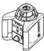
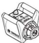
KoIeHeN Kyn Tk Kyu
Oniwey KypaibH KeIeHeH HeMece TIK Kynde TypaTbI 6etKe opHaNactbipBn, WtTaTHBke (38) HEmec Keabipfa 6ekitkiine (42) Typanay 6nOrbImeH opHaTbHb3.
KofapbHNBennpNey dAnirine 6aNaHbCTb 0nwe Kypanbl dipire KHe Kye3repictepihe eTe ceImTAN kayan KaIapadB. CoNdbkTah KocbIMwa HNBennpNeY ce6e6iHe 6oIaBH Kymbc yainicptepin and bH any uHnwe KypablnbH TpaKbTI KyHKe3Ketki3iH3.
Kocy@wipy
OJy KpaBnKocy yuH Kocy/uyipy TyMecin (4)
bAcbH3. BapNik HnDnKaTOpnap KbcA yaKbITKa xaHaDbI.
OJy KpaBn AaHbMaJI naep Caynci (6) XeHe
KofapkapaTbIFAH nepneHdNkynp TaBaHbN (9) WbFapy
CaHbNaayapBHaH (8) xi6pepi.
- Na3ep cayneciH aadamapFa Hemece XaHyapnapFa 6afbTTamaHbI3 XeHe tini anbictan GOncbH Xapblk ceynecine 03iH3 kapaMaHbI3.
OIIeey KypaIbI abTOMaTTb TypDe HNBenIppey apeKeiH 6ipEn bactaIdb. HNBenPpey KeiHne Ky INdkaTopbI (3) Xacbl TycnE HkblbIKTaI, na3ep aHaMaJ XblbIKTaIbI.
KyHnHKatopbl (3) y3diKc3 xacbl Tycne HkaHbIn, naep y3diKc3 xhaHbIn typrHa, 6yn enuwe KypanblHn HNBennpHeHH 6inipei. HNBenpNeY aKaTaHaHaH KeHH, eUwe KypaBb ABOMaTbI TypDe potaunblaIK Kymbic peXmHne Icke KocblNaBl.
Kocynb3apaykypabih6akblaycb3 Kandbipmahizxaneonwey kypabih naanahyaeh coHewipin3. Naep Cayneimeh aamapdbH Ke3IH 1aFbIbCTbpy MymKH.
PotaunnbpeKIM TYMecHIN (5) HEmeC cbl3bIKTBk peKIM TYMecHIN (11) KOMerImeH HBeJInpEy 6apbcihda JyMbIC peKIMH anDbH ana bEnrinyre 6oana. ByJ KaJaHa HBeJInpEy aKaTaNFaHHaH KeiH, eNwey Kypalbl TaHaHaH KymBc peKIMHneIe Icke Kocblnabl.
OuwekykpaBihewipy ywiH Kocy/ewipy Tymecin (4) KaTadah6acbHb3.
Oneyky KypanbI 2 carfattah y3ak e3dirihen HnBEnnpey
aMaftbHaH TBIC BCnCa Hemece cokkbl typanbl eckepty
2 carfattah y3ak kymblc ICTEN Tpyca, Oneye kypanbl
6BataperaNapbl Hemece akKymyTropnapbl KopFay yuH
ABTomatbl TypeE eWIn KaJaBl. Oneye Kypanbl HkaHaDaH
OpHaNaCTbIPbIN, KaTaNKOcbHb3.
PaiDanaHy typepi
KymbicpekHmdepihe wOny
BapnbK 3 Kymbic pekHm i enwey KpaIbHbN KeIeHe HKeH e TIK KynHne Kymbic icTei.
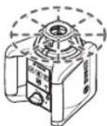
Potaunabkpekm
PotaunnblkpeKIM acipece na3ep Ka6blndafbshnnaDanaHraKe3e YcbhInaDb. 2pTpyni aHany KblnDaMbIKapbHbH apacbHa TaHayfa 60anaB.

Cb13bIKTBiKpeXHM
By npekmde aHbimabI naep cayneci
wektenre hCaBnay 6pybiuHda
ko3fanaDb. Ocbina naep cayncinH
Kepepni potaunnyk pekmre
kapafahda aptbik bonaDb. optyni
cahblay 6pybiHTapbIH apacbHa
Tahdya 6onaDb.
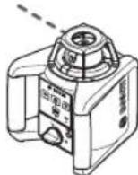
Hyktenipexmm
BypeKIMde aHbImaIbnla naep
cayneiciH y3dk Kepepiriine kon
kTei3neDi. On,Mbicnbl,6niKTKeTepdi
Oah Keipipy Hemece e3ikTectiTekcepnyiin naDanaHbIaNbl.
Cb3bIKbIKKaHe HkyTei peKmepnaepe Ka6bIaRaBIMeH (36) 6ipre naDanaHyFa apHaMaFaH.

Potaunnblk xmbicpexnmi
OJnwey KypaJIbI aP KocBInFaHHaN KeiH CTaHapTTb aHaJIy KblJaMdbIfbIMeH (300 MHN-1) poTaunbIKpeKHMde 6oanaJIbI.
Cb3bIKbIKpeKIMMHeH potaunlkb peKIMre aybcIyUH poTauNlkb peKIM TmecIH (5) HeMece KaUbIKTaH 6ackapy KpaJIbIHpoTauNlkb peKIM TmecIH (26) 6acbHb3.
AHHany KblIaMdbIbH 03repy yIiH potaunlkbK peKHM TyIMecIH (5) Hemece KaIbTKanB 6ackapy KypanlbHIN potaunlkbK peKMM tyIMecIH (26) KaKeTTI KblIaMdbIKKa KonketkiReHwe 6acblb3.
Ja3ep Ka6bIJa8bIbIMe XyMbIC icTeRe H Ke3e eH XoFapbl aHany KByIaMdbIbIH TaHay Kepe. Na3ep Ka6bIJa8bIbHcB3 XyMbIC icTeRe Hne Ja3ep caynecHH KepePirih JkacCapTy yuH aiHany KByIaMdbIbIH TEmHeTInJ3 XaHe Ja3ep Kepy Ke3inDipiriH (46) naJaHaHbHb3.

Cb3biktbikpexHM/hyKTei pexHM
Cb3bIKTBk HEmeCyHyKTei JxMbcpeKIMHe aybicyyuih Cb3bIKTBk peKIM TYMeciH (11) HEmeCe KaBbIKaBacKapy KypalibHcBc3bIKTBk peKIM TYMeciH (27) 6acbHb3.
Oney KypaIbI Cb3bIKbIKpeXnMRe eH KiWi apanblk 6ypbblHa aYbicaBbl.
CaHbIay 6pybIbIH 3repty yIWc bIbIKbIK peKHM TYmecIH (11) HEmece KaIbTKaH 8ackapy KypaIbIHbIH cyIbIKbIK peKHM TYmecIH (27) KaJxETTI KymbcpeKHMHe KTeKeHwe 8acblH3. CaHbIay 6pybIbAp 8ackah caBH DeHReB 60bIHwYkKeiin, dAn con yaKbTTa aHany KbldAmblfAp DeHReDe KeTepinei.
Ynkeh cahblay 6pybshbHna eIwey kpaanbl kbicKa KocbMwadipinde HKeIN HkyTei peKmre aybcabbl.
Cb3bIKTBkpeKIM TYMeCi (11) KaTaN6acBnFAHa, eH KIiHa CaHbIay 6pybIbHa He cb3bIKTBk peKIMrKaNTacBt3.
Hyckay: Hnepura 6aNaHaBcTb Na3ep cb3bIfbHbIH aKbIPfbl HYKTEciHEa3FaHTa N3aeP bIbN KaNYbIMYMKH.
Функцнлар

AHHanyKa3bIKTBfBHBHihIHHe cb3bIKTbI/ypay (A cypetin KapaHb13)
OIIeuy KypaIbIHbIH KJIeHEn KHyIHJe Na3ep CaynciH HeMece Na3ep HyKTeciH Na3epH aHaHany Ka3bIKbIFbIHbIH iHHe opHaIacTbipyfa 60ana. 360^ IaMaCbHa 6ypayfa 60ana.
On yuHn potaunbik 6actneKti (10) KOJIMe KAKETI KYRE 6ypaHb3 Hemece KaUbIKtan 6ackapy KpaBih NaiDanaHbHb3: CafBT TINIH 6faftbIMeh 6ypay yuHn KaUbIKtan 6ackapy KpaBihN CaBT TINIH 6faftbIMeh 6ypay TYMeciH (29), an caFAT TINIH 6faftbHa Kapcbi 6ypay yuHn KaUbIKtan 6ackapy KpaBihN CaFAT TINIH 6faftbHa Kapcbi 6ypay TYMeciH (30) 6acbHb3. PotaunbIK peXHMde TyMeepin 6acblnyeew cep etneji.

AHHany Ka3bIKTBfBtH TIK Kynde 6ypay (Bpaapab13)
OJIeY KpyaBbHbH TIK KyiHHe Na3ep HkyTecIH, Na3ep Cb3bIFbH HeMece aHany Xa3bIKbTFbH OHa TeHecTipy HEmec npannenbI typanay yuH ±8% WAmacbHaFbI dnaanaohda TIK Ocb 6oBuHwa 6ypayf6 gonabI.
Cafti TiniH 6aftiTbImeH 6ypay ywiH KaWbIKTaH 6ackapy KypalibHbH Cafti TiniH 6aftiTbImeH 6ypay TYmecih (29) 6acbl3.
CafttiniH6aftbHaKapcby6ypayyuiKaWbIKTaH 6ackapy KpaJIbHbH CafttiniH6aftbHaKapcby6ypay TYMeciH (30)6acIbI3.
HNBENHPneyaBTOMaTHKacbl
Wony
Oniwe KypalbKoIeHxHe TIK Kydi ABToMaTbI Typde aHbIKTaIdb.KeIeHxHe TIK KyInePInapacBHa aybcy yuH eIwe KypalbH oipin, KaHaDaH opHaNaCTbIpbHb3 XHe KaTt KocBbI3.
Ouwe Kypaib KocbifraHH KeiH KOndeneH HeMece TIK Kydi TeKcepin, WAmMaHe ± 8% (± 4,6^) 33irHe HBeInpNeY Dnana30HbIH AcbHda 6yblpblbIKtbl ABTomatbl Type TsyteTJI.
HnBEnnpIeYKe3InDeKyHnHnKaTOpbI(3)JXacblTycne HkblbIKTaI,na3epaHaMaM KblbIKTaIbI.
KyHnHaKaTOpbl (3) y3diKc3 xacbl Tycne HkaHbIn, na3ep y3diKc3 xhaBIn TyPfAHa, 6yn eJlwey KpaIbHbH HNBenIpHeRehin 6iDipedi. HNBenIpNeY aKtaTaNFaHHa KeiH, eJlwey KpaIbABTomAtbTyPde potaunblaIK KyMbIC peXmMInDe iCe KocblNaDbI.
OIIeuy Kypanbl KocbllrFaHHaKeIH Hemece Kydi e3repKehHEn KeiH 8% WAmcBHaH apTbIK KncbIK Typa, HBebpnpey apekeTih 6yDah 6blnApbHday MymKiH 60mAbI. ByN KaFdaNpaTOpTop ToKtan, na3ep KblbIbIKtaJbI Da, Kyu HNDkAToPbI (3) Y3dIKc3 Kb13bl TycneH KaHbIn TpaBl.
Thiwey KypanbH KaHaadAn OphAnaTbipBn, HNBennpney opbHdAflFaHwa KyTe TpybHbI3. KaHaadAn OphAnaTbIpy
opbHdAmaca,2MHHTaH KeiHa3ep,an 2 caraTah KeiH eIwey KpaJIbI aBtOMaTTI TypDe eWIn KaJaDb.
OJwey KpaIbHnBEnPneHReHHeKeiH KjyeiTypde
KeJeHeH XHe TIK KyI TeKcepei. Ky eRepreHne,
KocbIMHa HnBEnPney aTOMaTTb Type opbIHdaAdb. KaTe
enwey opeKeTIH anDbIH any yuHn HnBEnPney bapbcihDa
potop ToKtaI, na3ep KblbblkTaI Da, Kyi
HNdkaTobpI (3)Xacbl TycNeH KbInblkTaIbI.

CokbI typanblcckepTy yHKnncbsI
OJy KpaJIbHa cokKbI typaI bckepTy yHKnrcbI bap. Byn yHKunrae JIyey KpaJIbHa kY e3repictei Hemece Tep6eny opbIH anFaHd Hemece actHbI bET dipindereH KaJaAa 3e3reptinreH n03uHa HNBenpny Re KOJ 6epMei jxHe OcbInaW aJIwe KpaJIbHbIH XblNkBn KetyiHc BonatbH Kateneepin andbH anadbl.
Cokbl TypanbI eckeptyi Kocy/6encnHidy:COKkbl TypaJIbECKePTy TYMecin (2) 6acblb3.CokKbTIypaJIbECKePTy HINIKKaTOpBI (1) y3iiKci3 JAcbl TycneH JAnbI typaJIb. CokKbTIypaJIb ECKePTy COKKbl TypaJIb ECKePTy cyHKUncBIn KocKaHHaH KeiH 30 ckyHdTai JxMbic icten TypaJIb.
CokkbyTypanbIeckepTy icKe KocbnBb: eUwey KpaBnH Kyin E3repKHe Ke3ne, HNBenPney dAnirHIN dnaana0hBHaH acbpFaH HeMece KaTb Dipin TipKeHNrKaFdaJa, COKkByTypaBleckepTy icKe KocBnDa: naepDi anHaNy bTOkTaN, Naep Caynci KblnbIKtaNDbA, Kyn INDnKaToPb (3) cHeNi XHe COKkByTypaBleckepTy INDnKaToPb (1) Kb3bl TycneH KbInbIKTaNDb.
AfbIMdaFbI KMyMbic peKmI KaJaKa caKaTaIaIbI.
CokkbyTypaibleceptyickeKocblfahKaFdaHda,enwey KypalbHdaftbCOKkbyTypaibleceptyTuMecin(2)hemec KaBbIKTaH baccapkyKpalaHdaftbCoKkbyTypaibleceptydi 6actankbkyirekaTapyTuMecin(28)bacbH3.CokkbyTypaibleceptydyHKunraCbKaTatahickeKocblbIn, enwey KypalbXymbcbHnBeNlpneyapeketinen 6actaDb.0Iwey KypalbHnBeNnpEnHReHHeKeiH (kyu INHdkatopb(3) y3dikciKacblTyCnEHKaHbIn TypaB),on CaTaNFAH XyMbICpeKIMHDe ickeKocblaDb.
Ehni naep CayneinH no3nncBcH aHbiktamabik HkyteTekcepin, eHwe KypalibHbH 6nKtirH Hemece Tpaanahyih KaKeTIHeTye3ETiH3.
ErepcoKbIypanBecepeTyickeocblfHaJkaJaIda,
yHKnuaeHlwey KpaBlnHdaFbIcOKkBiTypaBlecepeTy
TMyMeciH(2)HEmeceKaBtTaBackapy KpaBlnDaFbI
COKkBiTypaBleceptydi bactanKbIKyIe KaItapy
TMyMeciH(28)6acyapkbInbKaNTa icKeKobImaca,
2MHHTAHKeIHNaepXaeHeXe He 2 carATah KeIH eIwey
KpaBbIABOMaTTbI Type eWedi.
CokkTypaIb eckepy fynKunacBn ewipy:COKkTypaIb eckepy tyHmecin (2) 6ip pet HeMece cokkTypaIb eckepy icke KocblfHaHa (cokkTypaIb eckepy HndnKaTOpbl (1) Kbl3bn TycneH kblnbikTaNb) ekipet bAcbl3. CokkTypaIb eckepy ewipyni 6oNFaHda, cokkTypaIb eckepy HndnKaTOpbl cHeidi.
Hcykay: Kaibtah Bacapky Kypabimc HcKbI TypaIb I cKepty FyHKuncbIH Kocy HeMece eWipy MymKIn Emc, TeK icke KocBnFaHHa KeiH KaTAticke Kocyfa 60ana.
Oney KypanbHbN dAnirin TeKcepy
Danik acepnepi
Kopway TemnepatypacbE h KWTi eep etedi. EeHneH KOFAbfa 6oFHaTemnpatypa e3repictep i na3ep cayncin aybIKybl MymkH.
EeH XaftbHbHda Temnepatypa 03repictepi KaTb6oNfaHb yuH eHwe KpaBb120 M KaBbKtBkTah 6actan 7taTNBke opHaty KepeK. OIwe KpaBbMymKIniIK 6oBbHsa KMybc aHaMaFbHBH OpTaCbHa KoBbHb3.
Aybitkynap WAMAMeH 20 M KaawbiktbIgTah 6actan Mahtb3dbl 60bn,100M KaaWbIktbIgTa 20 M ayitkydaeh eki ecehen Tep ecere dein Hynkeh 6onybl MyMKIN.
Cbiptkbi acepnpenTbic acnantbik acepnppe (Mbicanbl Kaftlbic HeMece KaTbCOKkbnap) ayltkynapfa anbin Kenyi MymkiH. CoI ywiH ap KymbictaH andbH HNBenipney dndirih TekepiH3.
Erep enuwe Kypalb TeKcepy Ke3iHne MaKcMaIbbl ayltkydah acbipca, OHb Bosch cepBnctik optanbIfbHaJxHndi.
KoIeHKe KyiEer HHeBnHpNey dAnDrirTeKcepy
Tnicti khe nan hntkere kon keki3y yuhi, 6epik bette KaabpdaH 30 m wamacbHdaftb epkin enwey KaBkTBfBHaTe Kcepyre KeHec 6epinei. OcTepeH ekeyi De tonblk enwey npoeDypacbHaH anK3iH3.
-0nwey KpyaBbH KeIeHeH KyIe Ka6bIpradaH 30 M
1aMaCbIHdaFb apaKaWbIKbTKa TtAINBKe MOHTaJHaHbI3
HEmece OHb bepik api teric beTke KoBbHbI3.0nwey
KpyaBbH KocBbHbI3.
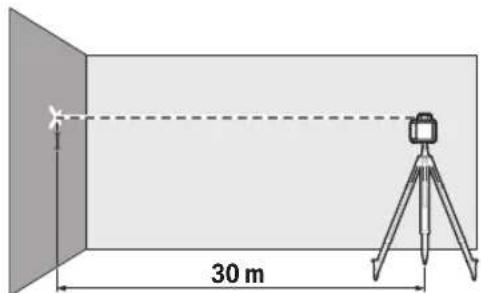
-HnBennpny aanktaIraHHaH KeiH,naeep cayneciH optacbHKabiprada(1HyKTe)benrineH3.
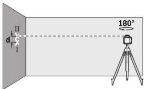
-0nuey KpyaBbH No3uHcBbH e3reptnei 180"uamacbHa 6ypaHbI. HbEnpNeydiOpbHdAn, Ka6bIpFaJaB (II HYKTe) naep CaynciHOpTacbH BeNirineH. II HkyTeHi I HkyTeHi YCTiHeH HeMece ActbHah BapbHwa TIK opHaJacaHbHa Ke3 KETk3iH3.
Ka6bipra4aFb6enrIneHReE1XeHEIHyKTeHH d aBpMaBnBfB0neHeTihOcbyWInEnWey KpaBHBH, dAn6nIKtIKTeayBtKYBHKepeTei.
Oneyepeketih6ackaocb yuiinKaIanahbi. On yuiin enwey epeketih 6actamac bypbH enwey KypanbiH 90^ Ka 6ypaHbi3.
30 m enwey KaBbKtbIbHda pyKcat etinreH MaKcMaIdbaytky:
30 M × ±0,1 MM/M = ±3 MM. Ocbina Ma I MeH II HkyTepe apacbHaFb d aHbPmaBbIbFb EKI eNlwey apeketHHApKaHcblcHda EH K6i 6 MM bonykepek.
PaiDanaHyckaynapbi
BenrinyuHApdaibmTeKnaepnIKhykTeHHemeacnaepnikcb3bIKTBH,OpTacBH naDanaHbHb13. Naepnik HkyTeHH enWeHmecec naepnik cb3bIKTBH eHI KaWbIKbKnEepepi
Ia3ep HbicaHbIK TaKtacbIH naJaAnaHy (MbHa cpeTti KaapaHbI3: C)
Ja3ep HbicaHbik TaKtaCbl (47) KolaNcbIg KaFdaJaKaHe Y3aK KaBbIKbIKTapDa Ja3ep cbIsbIFbIH KepiHicH KaKcapTaBl.
Ja3ep HbicaHdbIK TaTacbHbIH KaTapaTbH Ja3bIKTbIFbl (47) Ja3ep Cb3bIFbIHbH KepiHyH JkaKapTbIN, MEnIp Jka3bIKTbIFbl apKbIbI Ja3ep Cb3bIFbl Ja3ep HbicaHbIK TaTacbHbIH apTbHaH da KepiHei.
UtaTHBneH KymblicIcTey (Kepek-KapaK)
WtATNB 6nIKTirH petteyre 6onatbH, typaKtB tOnwey tiPerIH YcbHAbI. OJnwey KypaBbH 5/8 IOHMik WtATNB 6ekitkiimEn (21) wtaTbTIcH (38) npEOKMacbiHa opHatbH3. OJnwey KypaBbH WtATNbTERi 6ekitkiw 6ypaHdAmEH 6ypan 6ekitih3.
Ibfbcihnae anem kkanacbi 6ap tataBte 6niktke3epicin tikenen petreyre 60ana.
Thiwey Kypaibin Kocyaan andbin HtaTnBti 6afblntahb3.
WM 4 ka6bipra 6ekitkiimEn (kepek-kapaK) xymbc ictey (D cypetih kapaHb3)
Oney KpaanbH Ka6bipFa 6ekitkiuine De typanay 6nBtmeH (42) MoTaxkayfa 6onabdi. On yin H Ka6bipFa 6ekitkiuhiH 5/8IOHMdk 6ypaHdacbiH (44) onwey KpaanbHaft WtaTHB 6ekitkiuine (21) 6ypan kipri3iH3.
Ka6bipfaraMOHTaXday:Ka6bipfaraMOHTaXday,Mbicanbl, WtATNB WbIFatBn 6nIKTirHeH KOFapbl HEmec Tpyakbl Emec 6eTTe XaHe WtATNCi3 XyMbic icTeHeD ycbHbnaBl.
Ka6bipra 6ekitkiuH (42) 6ypaHdaanapdbH KOMerimeh
6ekitkiu cahblaynap (40) apkblb Ka6bipfara Hemece
6ekitkiu 6ypaHaBbH (39) KOMERIMEH peKaFA 6ypan
6ekitih. Ka6bipra 6ekitkiuH Ka6bipfara MyMknirihue
TIRHeH MOnTaXdAn, TypaKbI 6eKITINReHIne Ke3KeTkiiH3.
UtaNbke MOThaXday:Ka6bipFa 6ekTkiuH (42) dAn OcbHdai JxONMeApKbI JxAKTaFb UtaTHB 6ekTkiuImeH (41) UtaNbke 6ypan opHaTyfa 6oJabl. MyHdai 6ekity tacini acipece aHaany Ka3bIKTbIfbI aHbIKTaMaJIbIK Cb3bIKKa 6afttJfAH Ke3de YCbHbJaBl.
Typanay 6bnbHbHKemEImeMHOTaxdAnFaH eIwey KpaBbH WAMaMeH 16 cm dna3oHaTirHe (Ka6bipfara MoTAXdaFah Ke3de) HEmeCe KeIeHeHHe (WtATNBKe MOHTXdaFah Ke3de) XblkByTa760ana. On yiwH typanay 6nOrbHdaFb 6ypaHaHb4 (43) 6ocatbIn, eIwey KpaBbH KaKeTTi KyIe XblkByTBHbI Da, 6ypaHaDaHb4 (43) KaTadaH 6ypan 6ekitih3.
Ja3epKa6blIaFbIbIMeH(KepeK-kaPak)XyMbicictey
Koaicbi3 kapbIKtbik KaJaDbihDa (kapbIK Kopway, Tikeen KYN CAYnepei) KHe y3ak KaWbIKTbIKTapda na3ep cb3bIKTapBH KAKCbipak aHbIKTay WsiH na3ep Ka6blndaBbHbIH (36) NaJdaNaHbHbI3.
BipHeWe JyMbIC peKIMi 6ap potaunnblk naepneppe HJXOFApbl aHany KblDAMdbIFbIMe HKeIJeHc HEmec TIK JyMbIC peKIMIH TaHdaHb3.
Ja3epKa6bIaFbIbIMeHxMbic icTey yIW OHbIH naJanaHany 6oBbHwa HcckaynbFbH OKblOpbHaB13.
Kaibtah 6ackapy Kypanbimeh xymbcictey
Bacapy TuMepeh BacKaH Ke3e, eIwey KypaBih HNBenipney peKmIHEn WbIrFapyfa Bona,bi, coHa aHany KbICa yaKbITKa ToTan KaNa,bi. KaWbIKtAn bCapy KypaBih naDanaHy apKbIb6yn acepre kon 6epinmeDi.
Kaibtah backapky KpaibHa apHaJfah DaTnKTeP (7) 0Iwey kpaibHbH yJX KaftHda, MbCaJIb, anDbHfb JkaTafbl backapny naHeiHIn YcTIHe opHaNaCah.
Onweriw peKamen (Kepek-KapaK) Kymbic icTey (E CypetIN KapaHb3)
Terictkepi Tekepy HeMece Kynama Kepnepdi 6enrineyuih naep Ka6bIaRaBbIme bipre enwirip eKaHb1 (37) naianahyra Kehec 6epinedi.
OJWerIi peiKaHbH (37) yCtIHe caJIbCTbIpMaJIb EJWeM WkanaCbI bEnrIneHReH. ObH HEnDik 6NkTirH IwIbFbCTbH actbHfbl KaftbHa TaHdayFa 6oJaB. OcbJaMa MaKcTaBb 6nIKt aybTKyApBH TKeNe Kepyre 6oJaB.
Ia3ep Kepy Ke3inipiri (kepeK-kaPak)
Ja3epKepyKe3iJdpiriKopwayKaapbKtBfBHyC7r3ineJi。OcbnaiJa3epKapbFbKe3yiwHKaPbHpa60ana.
"TePmec" BO, 7 Ka6aT
Ten.: +7 (727) 331 31 00
c: + 7 (727) 2330787
E-Mail: ptka@bosch.com
CepBnCTIK Kbl3MeT KepcTeY optaIbIKTapbl MeH Ka6blnday nyHKTePiH MeKeH-XaBl TypaBl TOnblK XHe e3Ekl aKnapaTb Ci: www.bosch-professional.kz pecmna caTTan ana anacbi3
Kb3met Kepcety opTaNbIKTapbIHbH 6acka da MeKeHkaNapbIMbHa KepeH KapaHbI3:
www.bosch-pt.com/serviceaddresses
Kadekekapaty

3NeKtp KpyblfblapbH, AKKMynTOpnpabbl/ 6atapereanpbl, Kepek-KapaKTap MeH opayblTApbl Kopwafah opTa yuih Kayincis KonMeH KaTt eHcyopbHa xibepyKaXeT.

3neKtp KpyblfNapbH JxHe
aKKyMnIaTOpnapbl/6aTapeRanapdbTyPmbicTbIK
KOKbIcKa TaCTaMaHbI3!
Tek kana EO endepi yuin:
EyponaIbIK 2012/19/EU dIpeKTHBaCbHa cAnKeC
JapamCbIs 3IeKTp KpyblfBnApBH XHe eyponaIbIK
2006/66/EC dIpeKTHBaCbHa cAnKec akaybl HeMece
eckipren AkkyMnyTopnapbl/baTapeHnApbl b6BeNek XnHay
XHe KopShaFaH opTa yWIn Kayinci3 XoJmEn KaTt OHey
OpHbHa Xi6epy KaKet.
Româna
Service scule electrice
Strada Horia Macelariu Nr. 30-34, sector 1
013937 Bucuresti
www.bosch-pt.com/serviceaddresses
Eliminarea

Aparatele electric, accumulatorii/bateriile, accesorile si ambalaje trebuie predate la un centru de reciclare ecologica.

Nu elimina aparatele electrice si accumulatorii/bateriile impreunacu deseurile menajere!
OuHa He npEJaRaT PbIHa UV 3aUHTa HamaJIaBt Bb3PnHemaHe Ha CBetOBe.
OchrypBaIte peMOHT ha BaIHTe npOyKTn caMo ot KBaHnΦHcIIpaH ekCneptEn nepCOHaH n cMo C opHnHaHH pe3epBHN YactN. Toba rapAHTnpa 3ana3BaHe Ha 6e3oNaChocTtA.
He octabTte Deua 6e3 npK Hau3Op da pa6oTc H3-MepBaTeHHn ype. Te morat HeBOHIO da 3acnenT xopa
He pa6oTeB EKcNIO3HbO ONaC hpeA, B KOrTo HMa 3aIaIIMn TeuHocTH, Ra3OBe HIn npaxObe. Morat Da ce reHepnPaT NckPn, KOTo Da Bb3PnaMeHrT npaxa HIn npaHTe.
Доьннтейнуka3aHHЯ 3a6e3oNaCHOCT 3a GRL 250 HV:

He hacooyaBte na3epHnIbU KbM Xopa INKBHOTN H BHNMaBaTe Da He NOrpeHHe HENocpeDCTBeHO CpeSy na3epHnIbU HIN CpeSy HerOBO OTPaxKeHne. TaKa MoXeTe Da 3acJenTIte Xopa,Ja npuHHTe TpyoBN 3IONoLnyKn IIN Da nped3BnKate yBpeKdaHe Ha OUnTe.
Ako na3epHnT IbU nonaIHe B OuHTe, H3aTbOpTe Bb3MOxHO H-6bp30 HOTdpBnHete TnaBata Cn OT na3epHHnIbU.
DonbHHTeHH yka3aHH 3a 6e3oNaHocT 3a GRL 300 HV, GRL 300 HVG:
Bbpxy H3MepBaTeHnHH ypeI c npdpynpndntHa Ta6enka ca 06o3haueHH OTBOPHTe 3a H3nn3aHe Ha Na3epa. 06pbuaite BHHMaHHe Ha TAXHOTo NIOXKeHHe npH3non3BaHe Ha H3MepBaTeHnHH ypeI.
Ako TeKcTbHa CbOTBeTHaTnpdUnpndHtEnHa Ta6eHa He h Baun e3NK, 3aneTe npdn pBata eknnoatauOn OTrope Bbpxy Hero dOCTaEBHn CTnKeP Ha Baun e3NK.
PnH3noJ3BaHeToHa na3ep c na3epen Knaac 3Rcb6IIODaBaiTe HeBEHTyAnHO pInnoXHMn HauNoHaHNnpedncaHH. Hecna3BaHeTo Ha Te3n npedncaHH moKe da npedeN3BnKa TpyoBu 3noJnyKn.
M3mepBaTeHnHTypeTpr6BaJa 6bJe 06cnyKbaH cAmOOTIIuca,KoNTO Ca 3aNo3HaTHC HauHna Ha pa6ota C Na3ePHN ypeHn.CbrIacHO EN 60825-1 KbM TOBa MejDy DpyrTO CnAHa NIO3HaBaHe Ha 6bNOIOnHHTO Bb3- DeiCTBHe Ha Na3ePHNJIbU BbPxy OKOTO KOKaTa, KaKTo I npaBHnHTo pnpIraHa He 3aunTHn CpeCDtBA 3a H36rBaHe Ha ONaCHocHTte.
06o3haaBte 30HaTBA, B KOITo H3MepBaTeHnHypeD ce non3Ba, c NOxOJaTu Ta6eKn, yKa3BaUn HaHnHuEto Ha Na3epHn bChu. Taka npedToBpaTaBate HaBnHaHeTO B 3aCTpaWeHATA 30Ha Ha BbHnHn Nla.
He cbxpaHbBaIe H3MepBateHnHa ypeHa MeCTa,Ha KOnTO ToI ue e DoctbHen 3a Heo6yueHnHa. Nua, KOHTO He No3HaBAt HaHnHa Ha pa6ota C H3MepBateHnHa ypeD, MoRt Da ce HapaHr IIN Da HapaHr dpyrN.

He hacoubaite na3epnna IbU KbM Xopa HIN KBNTHN; He rneJaTe cpeu na3epnna IbU. To3n H3mepBaTeEN HNCTpyMeNT reHepnpa na3epno IbueHne ot na3epen Knac 3R cbIacHO EN 60825-1. POnadaHTo Ha Ibua Bbpxy ouHTe -Dopn n ako e T oJrMaO pa3cTOrHne -MoKe Da rN yBpei.
OchnpyBaIte KOHTpON HnH30nHPaNTe 3OHATA,B KOTo Ce pa3npocTpaHBaT Na3epHNTe IbU. OrpaHuaBaHETo Ha Na3epHNTe IbUH B KOHTpONIPAHa 3OHa npedotBpaTBA YBpeXdaHe HA OUnTe Ha CTpaHnHn Nla.
IocTaBnTe H3MePBeTEnHHH NcHCTpyMeHT BnHaHr Ta Ka, Ye Na3ePnHe IbY Da InpemHbAaT Ha TOnMa POa3-CToHNHe HaNn IOd BnCOuHHaTa Ha OHTe. Taka ce HAmaJIbBA OnaCHOCTTa OT YbpexJaHe Ha OHTe.
N36aBaeToOtpa3BaHetoHaNa3epnnaIbUOTrnaKn NOBbPxHOCTKATOpO3OpuNNOrneDana.NOBpeKDaHeHaOHTeE Bb3MOXHOITOPa3EHNAbU.
Дугун yka3aHHa 3a 6e3onacnoCT
He h3non3BaIe ONTHuHH cb6hpateHn HNCTpyMeHTn KATO daNEkoRneHnn nyna 3a Ha6IOJeHHe Ha3TOUHNka HaJIbueHHe. MoKe da yBpeInTe OHTe cn.

He NoctabnTe MaHHTnTe npHaJaIeHxocTn B 6nn3oCT Do HmPnAHTn N Dpyr MeHnCCKn ypeDn, KaTo HApN. NeCMeKbPn HnN HCynHOBn NOMn. MarHNTte Ha npHaJNeK-HOCTnte Cb3daBt None, KoETo MoKeJa Hapy-wn PhyHKUOnHpaHeto Ha HmPnAHTne nN MeHNCHkTe ypeDn.
DpbXTe MaHHTHTe npHnAdIeXHoCTHa pa3cToHHe OT MaHHTHn HOCTeHN Ha DaHHN H CyBCTBHeTNN KbM MaHHTHn NOneTa ypeHn. BcJeCTBHe Ha Bb3dEiCTBHeTO Ha MaHHTHOTo None Ha IpiHnAdIeXHoCTHe MOKe da Ce CTnHE Do HeBb3BpATmA 3aRy6a Ha IHOpMaunr.
He OTbaprAte akymyNatopHnTe HnO6NkHOBeHnTe 6aTepnn. CbIeCTByBa ONaCHOCT OT Bb3HNKBAHe Ha KbCO cbEINHEHe.
Pn noBpeKdahe H HenpaBnHa ekCnnoataun O atkymnatopHata 6aTePNaMOrat da ce otDenr Napu. AkymnatopHata 6aTePNaMoKe da ce 3anAn nn da eknlonpa. Iorpnke Te ca 3a do6po npOBetpBaHe n npn onnaKaBnHce o6bPHeTe KbM nekap. Napte Morat da pa3dpaaHrt dnxATEeHNTE nbTuca.
PnH HnpabHnHO n3non3BaHe nHn NOBpeHa akymy NaToph6aTepHnOT He MoKe Da n3teue eNEKtpoHT. N36raBaiTe KOtAKTa C Hero.AKO BbIpeKn TOBa HA KoXkata BN nonadHe eNEKtpoHT, n3nnakHete MCTOTO 0bHnO c BOda.AKO eNEKtpoNT nonadHe B OHTe Bn, He3a6abHo Ce 06bphete 3a NOMou KbM Oeyenekap. ENeKtpoNTbT MoKe Da npeHnBnKa n3rapHHHa Koxka Ta.
AkyMnyatopHata 6aTepeH MaKe Da 6bJe NOBpeHEnoTocpn npedMeH, HnP. NpOHn HnN OTHBepKn, HnNOTcHnH yapn. MoKe Da 6bJe npeD3BnKaHO BbTpew-HO KbCO cBeHNHeHne AkyMnyatopHata 6aTepeH MoKe da
ce 3anaHn, da 3anyu, da ekcnnohp a nn da ce nperpee.
PpeNa3BaIte HeHn3non3BaHHTe AkymyIaTOpH6BaTe pH NOT KOHTAKT C RONEM HIN MAKIM MetaHH PpeMeTH, HAPN. KNaMepH, MOHETN, KIOUOBE, INPOHN, BINTOBe H Dp.N., TbK KATO TE MORAT Da PpeH3BHKAT KbCO CbeEINHeHne. IocneCTBnRA To KbcOTo CbeHNHeHne MoRat da 6bDat n3rapnHn Hn noXap.
M3non3BaIte akymyIaTOphATA 6aTepeHnHa Bosch caMo B npOdyKTH Ha npOn3BOIDHTeN. CaMo TaKa akymyIaTOphATA 6aTepeHnCe npEJa3Ba OT onaCHO npETOBapBaHe.
3apeKdaIteakymyataopHaTa6aTePnHa Bosch caMo cdoCTabeHHTe 3apdHH yctpoiCTBa.
IpeNa3BaIte akymnatoHIne 6aTeepnO TOnnHa, HAp. BCNeCTBHe Ha npDbNKeTEnHO n3JaRaHe Ha DnPeKTHa CbHcYeBa CBETnHa,OrbH, MpbcoTHa,BOa Nblra.ⅢMa ONaCHOCTOT EKCIIIO3H N KbCO CbeINHeHne.
Yka3aHn 3a 6e30nacha pa6oTa cbc 3apAHH yCTpoiCTBa

Ipoouete BHHmatenHb CnKyka3aHnn HnHCTpykun 3a 6e3oNachoct. Iponyck npn cnaBaHeto Ha nHCTpykUnTe 3a 6e3oNachoct n yka3aHnTa 3a paBota MoRt Da Imat 3a Noc
JeCTBHe TOKOB yAp, NoXap H/nn TeKKn TpaBMn.
CbxpaaBaBte Te3n yka3aHHa HcHpyHo MxTo.
ToBa 3apAidno yctpoiCTBO He e npedHa3NaueHo 3a non3BaHe OT Deua n Nnua c Ogranuene Hn3nueCKN, CEN3OpHN nn DyweBHN Bb3MOXHOCTHnn 6e3 DoCTaTB4HO ONNT. ToBa 3apAidno yctpoiCTBO MoKe Da ce H3non3Ba OT Deua OT 8-rodnHa Bb3pact n Nnua c OgrapHHueHn On3NueeCKN, CEN3OpHN nn DyweBHN Bb3MOXHOCTHnn 6e3 DOCTaTB4HO ONHT, aKO ca NOd He-nocpeIcTBeH Na3Op OT Nnua, OTROBOPHN 3a 6e3OnacHocTTa NM, NN aKO ca 6nHn ObyuEHN 3a CNrpyHa pa6Ota Cbc 3apAHDto YcTPOIcTBO n Pa3bnpat CBbp3aHnte C TOBA ONaCHOCTH. B npOTnBEH cnY
yaBcBueCTByBa ONaCHOCT OT HenpaBnHIO NOn3BaHe N TpydOBN 3NoONyK.
CneedeTe deua npn non3BaHe, no- nuctBaHEnoDbpxaHe.Taka ce npedOTbpaTBA onacHocTTa deca da nIgparT cbc 3apdHOTO yCTPOINCTBO.
3apekdaite cmo Bosch NiCd/ NiMH akymnatopn6baternc kanaHTet 9 Ah (2akymnatopn KneTK).Hanpe- xehneTo Ha akymnatopHaTa 6a- terpna Tpa6Ba Da CbOTBeTCTBa Ha 3apndoto HapexeHne Ha 3apdHoto yctpoiCTBO.He ce ONHTbaTe da 3apeXdTe 6nKHOBEHn (Hea- kymnatopn) 6atepn. B npotn- BEH cnuya ChseCTByBa onacHOCT OT NOxap n EKCnO3n.

IpeNa3BaIte 3aepnHTo yctpoCTBO O TbJxN
OBNAHBAHe.IPOHKBaHTo HA BOJa B EneKTPoHCTpyMeHTA NOBnBaOanCHOCTTa OT KOKyDap.
3apeKdaTe H3MepBaTeHnH ypeC caMo c BKnHoyeHO TO BOKOMNKeTObKaTa 3apAHOyCTpoiCTBO.
IopdbpkaTe 3apdHOTO yCTPOcTBQ nCtO.CbueCTByBa ONaCHOCT OT TOKOB ynap BCNEcTBHe Ha 3aMbpcBaHe.
BnHaH npEHN pON3BaH npoBepBaHTe 3apJHOTo yctPoIcTBO, Ka6ena H uencena. AKO yCTaHOBITE NOBpeH, He NpON3BaHTe 3apJHOTo yctPoIcTBO. He ce ONHTBaHTe cAMN da OTbAPTe 3apJHOTo yctPoIcTBO; OONYCKaHTe peMOHTN da 6bDaT N3BbPbWBAH cAmO t KBaHfHnpuHn TexHnH cAmO c H3NON3BaHe HaOpHrHHaHn pe3epBn YacTH. NobpeHn 3apJHn yCTpoIcTBA, Ka6eni H uencenYyBeInuabat OnaCHOCTTa OTOKOB yIap.
He octabHte 3apJHto yctpoCTBO da pa60n Bbpy Xy necho3anANA mnoBpXHOCT (HAP. xapTn, nlat n T.H.), pecn. B necho3anANA cpea. IopaHn HarpBaHeto Ha 3apJHTO yctpoCTBO NO Bpeme Ha pa60ta cbIeCTByBa ONaCHOCT OT NOKap.
OnncannHe Ha npOdyKta n DeHocCTTa
MOnI, HmaiTe npEiDn I3o6paXeHnra T B npeHaT aact Ha pBkoBOCTB0To 3a paOta.
IpeHa3NaueHne Ha ypeDa
PotaunHnna3epn
H3MepBaTeHNHTyepe npeDHa3Hauehen 3a onpeDeneHe npOBepKa Ha cTporO xOpN3oHTaJIHn cTPONTeHn IINHH, BepTKaJIH, IINHH HNoPaBHBaHe H KOTH.
I3mePbATEENHITypeE nOxOJa3a pa6oHa OTKpITo H B 3aTBOpeH NOMeUHn.
ДuctанционнуynpaBNeHnE
IInCTaHNoHHOTO ynpabHeHne e npedHa3HaueHO 3a ynpabHeHne Ha Bosch potaOnHHn Ia3epn C HfpaepBeHN b-
IuctaHIOHOHTo ynpabHeHne e npdoJnO 3a ynoTpeBa B 3aKpHTN NOMEeHnHa OTKpHTO.
H3o6pa3eHH eIemEnTH
HomepnpaheTo Ha 306pa3eHnTe KOMIOHEHTe ce OTHACr DO H3OpaXeHHeTo Ha 3MepBaTeHnHa ypeI NINCTaHcNOHHOTo ynpabHeHne Ha rpaΦnHnTe CTpaHn.
PotaunohenIa3ep/3apnHOyctpoNCTBO
(1) INДИКАСИФУнКИЗ И рпсурпждэну уда.
(2) Bytoh 3a npedynpexkdenhe 3a ydap
(3) INДИКациHA CTaTуca
(4) NyckoB npeKbCba
(5) BytoH poTaunHOHe n peXnM
(6)Дижец селацерпьч
(7) Cen30p 3aДиСТанцINHоунр平方ENHe
(8) O TBOP 3a n3xODAIyIa3epeH nbY
(9)OTBecHarope
(10)Bbptraa ce rnaBa
(11) ByToH nIHeeH pexHM
(12) CnMBoJ 3a n3ToUeHn 6aTePnN
(13) Akymylatopha 6aTepeA
(14)Гнздо 3а 6атейнente
(15) 3actonopBaHe Ha rHe3IOTo 3a 6aTepeHH
(16) 3actonopbahe ha akymyataopnata batepna
(17) 3apnha6yKcaA
(18)3apnHOyCTPOHCTBO
(19)MpeXOBn aanTep Ha 3apAnHOy yCTpoiCTBO
(20) KoHTaKTeh Uekep
(21)「He3do 3a MoHTnpaHe KbM CTaTNB 5/8"
(22) CepheH Homep
(23) PpeynpeinteHa tabeKa 3a na3epHna Ib4
(24)Ппсдурпсдгтелна tabeлka n3xologen OTBOP Ha na3epa (GRL 300 HV/GRL 300 HVG)
A) N3o6pa3eHnTe Ha fHyprHe H onncAHnTe DonbHnHTenHH pNcNcO6bHnHe He Ca BKNIOUeHN B cTaNdAPTha OKOMnNeKToBkHa ypeHa. N3eepNaTeEN CnCbK H a DoNbHnHTenHHe pNcNcO6bHnMeKte Da HamePte CbOTBeTHo B KaTalora Hn 3a DOnbHnHTenHH pNcNcO6bHnE.
236|BbIrapckn
DuctaHnHO ynpabHeHne
(25)Дистанцоноуynравпени.
(26) BytoH potaiohoeh pexim
(27) ByToH nHeeH peXnM
(28) BytoH hynipaHe ha npedynpeJxdenHe npu yap
(29) ByToH 3a 3aBBpTaHe No yacOBHHKObA Ta CTeIka
(30) ByToH 3a 3aBbPtaHe 6paTHo Ha YacOBHNKOBata CTpeIka
(31) INDnkaaia n3npaaane Ha cnHan
(32)ИЗходенOTВОнИФпачepBEHObIьчЕнHe
(33) Cephen Hoomep
(34) 3actonopraBaHe Ha kanaka Ha rheaTo 3a baTeepn
(35) Kanak Ha THe3DoTo 3a 6aTepeHH
DombHHTeHHnPnHcNo6neHm/pe3epBn qactn
(36) Naapepeh npHemMHK
(37)ИзмерВATEннALEТБA
(38)CTaTHB
(39)KpenexhenBnHTNaDbpkaa3aCTeHaA
(40) KpenexHHN OTBOPn Ha DbpXkaa 3a CTHeA
(41) 5 / 8^ NOCTABKa Ha CTaTHB Ha Dbpxkaa 3a CTHeA
(42)Дьржачзастан/изразвнтейенMoун
(43) BnHT Bbpxy HpaBHNHmMoynA
(44) 5 / 8^ BnHT HaNbpbjkaa3aCTeHa
(45)MaHHT
(46) La3eprHn ouHa
(47) Nazeрна Мерпелна плоча
(48) Kyφap
A) N3o6pa3eHnTe Na fMyrpyHte HOnncHnTe OOnbHnTeHNn npcnocO6NeHHe He ca BKNIOUeHN B CTaNAPThATA OKOMNNEKTOBk Ha ypeHa. N3eepNaTeEN CnHcBk Ha DOnbHnTeHNHtne PcnocO6NeHMe MOXETe Da HAMEPTE CbOTBEHO B KATAIora Hn 3a DoNbHnTeHNn PcnCNO6NeHn.
TexHHueckn daHHN
Potaonnnaeepn GRL 250 HV GRL 300 HV GRL 300 HVG
| Каталожен Home | 3601K616..3601K615..3601K617.. |
| РавOTEN ДИАПAZON (радиус)A(B) | | | |
| -6e3лазерен п Rimемнок ok. 30 m 30 m 50 m | | | |
| -слazерен п Rimемнок ok. 0,5-125 m 0,5-150 m 0,5-150 m | | | |
| Точность на НИВЕЛРапe(A)C | ±3mm (при 30m) ±3mm (при 30m) ±3mm (при 30m) |
| ДИАПAZON на豌оматчно НИВЕЛРапe, ТИПЧИО ±8% (±4,6°) ±8% (±4,6°) ±8% (±4,6°) | | | |
| Вре'mе за豌оматчно НИВЕЛРапe, ТИПЧИО 15 s 15 s 15 s | | | |
| Сторост Ha вътөн 150/300/600 min | -1 | 150/300/600 min-1 | 150/300/600 min-1 |
| Бъл на OTваряп по плионец реким 10/25/50° | 10/25/50° | 10/25/50° | |
| РавOTHA Temпераразу -10°C ... +50°C | -10°C ... +50°C | 0°C ... +40°C | |
| Temпераразу ДИАПAZON за съхсаньанe | -20°C ... +70°C | -20°C ... +70°C | -20°C ... +70°C |
| Мамс.Robота Височи наад базовatable Височиа | 2000 m | 2000 m | 2000 m |
| Оту检пелна Влажноct Мамс. | 90% | 90% | 90% |
| Сторун Ha замьрсаньанe съласно IEC 61010-1 | 2(D) | 2(D) | 2(D) |
| Клас пазер | 2 | 3R | 3R |
| Тил пазер | 635 nm, < 1 mW | 635 nm, < 5 mW | 532 nm, < 5 mW |
| Ди捜гэнця | 0,4 mrad (пълени) | 0,4 mrad (пълени) | 0,4 mrad (пълени) |
| Посстбка за Stатих Хорзонтailinga | 5/8"-11 | 5/8"-11 | 5/8"-11 |
| Актулatorsыбетери (NiMH) | 2 × 1,2 VHR20 (D) | 2 × 1,2 VHR20 (D) | 2 × 1,2 VHR20 (D) |
| (9 Ah) | (9 Ah) | (9 Ah) |
| Баетери (аллално-mанганови) | 2 × 1,5 VLR20 (D) | 2 × 1,5 VLR20 (D) | 2 × 1,5 VLR20 (D) |
| Маса съласно EPTA-Procedure 01:2014 | 1,8 kg | 1,8 kg | 1,8 kg |
| Размери (дьлжина ×ширина × Височиа) | 190 × 180 × 170 mm | 190 × 180 × 170 mm | 190 × 180 × 170 mm |
Potauonnnnnaepn GRL 250 HV GRL 300 HV GRL 300 HVG
| Вид зашита IP 54 (заштон срецу
празх и ворDNи пьсКи) | IP 54 (заштон срецу
празх и ворDNи пьсКи) | IP 54 (заштон срецу
празх и ворDNи пьсКи) |
A) npn 25°C
B) PnH e6IaropnraTHN yCIOBnA (HaNP. HENOCpeCTBeHN CJIbHcEeBn IbCh) paOHTHnT dHnA3OH MOKe Ja e N0-MaIbK.
C) ycnopeHn ha ochte
D)Ima cAmO He npoBDOHMO 3aMbpcBaHe, pN KOeTo o6aue e Bb3MOxHO Da ce OaKBA BpeMeHHO IpNpHHeHa IpoBOHMOCT Iopadn KOHDeH3. 3a eHOn3NaHNo HENTnHfHnpuHa H BaWnH3MepBaTeen ypeI cnYkX cepHHHT HOMe (22) Ha TaBeNKaTa HypeJa.
3apdno yctpoctbo CHNM1
| Каразожен Homep | 2610 A15 290 |
| Вхочио нареве V~ 100-240 | |
| Вхоча чECTOTA на поменNELвя ток Hz 50/60 | |
| Изухочио нареве V= 3 | |
| Изухочиш ток A 1,0 | |
| Дорустima temпература на akymунаторната bateрnia
при заразжданe | °C 0 ... +40 |
| Вреши за заразжданe h | 14 |
| Бpoи на кletкпe в akymунаторната bateрnia | 2 |
| Hominahlor нареве (на кletka) | V= 1,2 |
| Maca съласно EPTA-Procedure 01:2014 | kg |
| Клac на зашита | ☐ /☐ |
| Достанцунно управлице | RC 1 |
| Каталожен Номер | 3601 K69 9.. |
| РавOTHA зонаA) | 30 m |
| РавOTHA Temnéратура | -10°C ... +50°C |
| Temnéратуен диапазон за сбхсануBAнe | -20°C ... +70°C |
| Мамс. равOTHA височи наだ садаразытая височиа | 2000 m |
| Ото国安лна влажноCT макс. | 90 % |
| СтоENе на замberсяве сбласно IEC 61010-1 | 2B) |
| Бастор | 1 × 1,5 V LR6 (AA) |
| Маса сбласно EPTA-Procedure 01:2014 | 0,07 |
A) Ipn He6naponpnaTH yCIOBn (HAnp. HEnocpeCTBeHN CbHueBn bCh) paOHTnT dHaNa3oH MoKe Ja e No-MaJIbK.
B) Ima cama HnnpoBDIMO 3aMbpcBaHe, npn KoTo o6aue e Bb3MOxHO da oe ouKaBA BpeMeHNO npuHHeHa npoBDMOCT npapAn KOHe3. 3a eHOn3aHua HneHTnFkau HA nCTAHIOHHOT ynpabIeHne CnyKcn cepHHNHT Homep (33) Bbpxy Tabekata.
MOHTIpaHe
3axpaHbAHe Ha dncTaHcNoHHoTo ynpabIeHne
3a pa6oTa c dncTaHOnHOHTo ynpabHeHne ce npenOpbBa nON3BaHeTO Ha aKanHO-MaHraHOBn 6aTePN.
3aOTBapnHe Ha KaNaka Ha THe3nOTo 3a6atePN (35) HATNCHEte 3actOnOpRABaHTo Ha (34) B NocOKaTa, Yka3aHa CbCCTpeNka, H MaxHeTe KaNaka. NocTabe 6atePnra.
BHHMaBaIte 3a IpaBnHnHaTc Hm NOnpHoc, H3o6pa3eHa Ha
ΦHypaTa OT BbTpEshHaCTpaHa Ha THe3DoTo 3a 6aTePHN.
H3BaTeTe 6aTepeHraOTdctauHnHOTo ynpabne Hne,ako HAma da ro h3non3BaTe 3a no-dbIro BpeMe.
PnpoBnKntEnHO CbxpaHbAbe B DuctaHNOHHTO
ynpaBneHne 6aTePnTa MoKe Da KopoDnpa N da ce camOpa3peN.
3axpaHbHe Ha n3MepBaTeHnHn HnCTpyMeHT
I3MepBaTeHnT ypeI MOeJa 6bJe 3axpaHbAH nIc o6NKHOBeHN 6aTePn HnC aKymyNaToPn 6aTePn Ha Bosch.
Pa6ota cakymnataopha 6aTepe
Cb6pa3HBAIe Ce c HappeKeHMeTo Ha 3axpaHbAaTa mpeXa! HanpeXeHHeTo Ha 3axpaHbAaTa MpeXa Tp8Ba Da CbOTBeTcBA Ha DaHHTe, HAnncn Ha TabekKaTa Ha 3apdHOTo yCTpoiCTBO.
3apeTeAkyMylaTopHata6aTePnna (13) npenI pBpTa pa- 60ta.AkymyIaTopHata6aTePnmaMoKeJa cae 3apeKda cAmoc npeBHeHOTo 3a TOBa 3apJHo yCTpoiCTBO (18).
IbXHeTe IopxOaIa 3a BaAata eNektpuecka Mpeka Uencen (19) B 3apAnHTo yCTpoCTBO (18) n ro fHKcapai-Te.
IbXheTe Uekepa (20) Ha 3apnHTo yctpoCTBO B6yKcata 3aapeKaHe (17) Ha akymaTOpHaTa 6atepn (13).
Cbpxte3apHnOyycTPOINCTBOKm3axpaHbaaataMpeKa.
3apekdaheToHa npa3Hata akymyntopHa 6atepna H3NCKBa OK.14 h.3apnHOTo yctpoCTBO n akymyntopHaTa 6atepna ca o6e0naceH cpeu np3apekdahe.
HobnnpoBnKHTeHbPeme HEn3no3BaHa akyMnaTopHa 6aTepeHra nKnHnCn KanaTe EBA cIe OK.5uKaBnHa Ha 3apeXdaHe n pa3peXdaHe.
He 3apekdaTe akymyaIopHata 6atepna (13) cneB CBAynoTpe6a, Tb KaTO B npOTnBEH cnuya KanaaTebT I ue CeHAMAI. 3apekdaTe akymyaIopHata 6atepna Camo Korato npedynpexdHeMeTo 3a 6atepna (12) CBETN MMRa.
CbueCTBeHo CbKpateHo BpeMe 3a pa6oTa cneI 3apeXdaHe noka3Ba,ue akymnatopHata 6atePn e n3xa6eHa n Tpa6Ba da 6bde zameHeHa.
Pn npa3ha akymyataopha 6atepma Moxete da n3no13bate H3MepBaTeHHN ypeD n C NOMOHTA Ha 3apdHOTO
yctpoCTBO(18),akoToe Cbbp3aHO KbM Mpekata.N3KIOUeTe N3MEpBaTeHnH ypei,3apeTe AkyMynatopHata batePnra 3a OK.10 min n OTHOBKIOUeTe N3MEpBaTeHnH ypeI Cbc Cbbp3aHO zapAINO yctpoCTBO.
3aCMHa Ha akymyataopHata 6atepe (13) 3abbpTe3actonopbaHTo (16) B NONOKeHne H3TereNte akymyataopHata 6atepe OT h3MepBaTeHHn ypei. IbxheTe HOaakymyataopHa 6atepe B h3MepBaTeHHn ypei n 3abbpTe3actonopbaHTo (16) B NONOKeHne
AkoHama Da H3nON3BaTe H3MepeBatenHny ype npoDbNkHTenHO BpeMe, H3BaTeOT Hero akymyataTopHaTa 6aTepy. Pnp npOblKNTENHO cbxpaHeHne B H3MepeBatenHry ypeakymyataOpHTe 6aTepyn MoRaT da KopoDnpat nn da ce pa3peJr.
Pa6Ota c 6oNkHOBEN 6aTePHn/akymyntopHn 6aTePHn
PpenopbUba ce 3a pa6oTa c H3mepeBateHnna ype da ce non-3BaT aIkanHO-MaHraHOBn 6atepn nnnn akymnatOpn.
3a OTbapnHe Ha Kanaka Ha THe3DoTo 3a 6atePn (14) 3aBbPte 3actOpBaHeto (15) Ha No3uN H3TeTne THe3-DOTo 3a 6atePnOT N3MePbATEHnpyed n noCTabete 6atePnnte, peCn. akymyNatopnnte 6atePn.
BHHMABaIte 3a npaBnHATA NM NpAphOCT, H3o6pa3eHa Ha
fHypata OT BbTpeuHATA CTpHa HA rHe3DoTo 3a 6aTePHN.
BHNr CmEHrTe BCnKu 6aTePHN, pecn. akymyNatOPHIne
6aTePHN eHOBPemEHNO. H3no3BaIte cAmO 6aTePHN INn
akymyNatOPHn 6aTePHN Ha eINN PpOH3BOHNTEN C eHNaKbB
kanaHTe.
H36ytaIe THe3dOTo 3a 6aTeepHH (14) B H3MePbAteJIHH ypeN 3aBbPtTe 3actOnopBaHeto (15) B NOJIOKeHne
Korato Hama Da H3non3BaTe H3MepBateHnHa ypeD npOdbNxHTenHO BpeMe, H3BaXdaJIte 6aTePHTe, pecn. akymyataTOPHnte 6aTePHN. PpI npOdbNxHTenHO cbxpaHBAHe B H3MepBateHnHa ypeD 6aTePHnte H akymyIaTOPhNTe 6aTePHN B H3MepBATEHnH INCTpyMeH T MOrat Da KopoOpHap N da ce camopaaPeJAT.
HdkaTop 3a CbctoHHeTo Ha 3apeXdaHe
Ako npdynpexdeneHTo 3a 6atepna (12) npemra 3a npbB T B cepbeHo, n3MepBaTeHNHrTypeD MoKe da ce H3nO3Ba oue 2 h.
Ako npdynpexdeneHTo 3a 6atepna (12) cBeThe B uepeHo, He ca Bb3MOxHn NOBuee H3MePbaHHa. H3MePbaTeHNHTypecne1 min aBTOMaTHuHO ce H3KIOUBA.
Pa6ota
Pepna3BaHte H3MepBaTeHnHn np6Op nHnctauHOnHHo ynpaBHeHne OT OBnaxKHaBe H DnpeKTHO noNaDaHe Ha CbHcEeN IbYn.
He H3naraIte H3MepBaTeHnnypeN nIINCTaHcUHOHTo ynpabneHHe HaekTpeMHn TemnepaTyprn Hn pe3KN TEMnepatypn npomeHn. Hanp. He nOCTaBnIe TbIIO BpeMe BAETOMo6n. PnroTOJemH TemnepaTyprn pa3NNK IIpbBO OCTaBnIE H3MEpBaTeHNH YApeN nDCtAHuOHHOy npabNeHne Da CE TeMnepnATn IINBkIOuBaIte CNEI TOBA. N3BbpWbaTE ppeN no-HaTaBbHa pa60ta C H3MEpBaTeHNH ypeD BNHar nPpOBepKa 3a ToCHoc4pe3 (Bx..PpOBepKa 3a ToCHocHa H3MEpBaTeHNH ypeD, CTpaHua 241).
PnEckTepeMHN TepeHApTuH NnI rOeMn TEmpeHApHn pa3NIKn TOuHOCTTa Ha H3MePBaTeJHHaypeMDoMe Da ce BNOUH.
136HBAte CnHH ydAPn Hn H3nyckaHe Ha H3MepeBaTeHHype. CneYdapHN Bb3JeCTBnB BbpxH 3MepeBaTeHHypeTpa6Ba Da n3BbpWBe IpoBepKa Ha ToUHOCTa My, IpEIN Da npOdbJXHTe Da To H3NoI3BaTe (BX. "PpOBepKa 3a ToOHcT Ha H3MepeBaTeHHype", CtpaHn- 241).
BknouBaHe Ha dHCTaHcHOnHHTO ynpabIeHne
PnHaTnCKaHe Ha KOnyEtata 3a ynpabNeHne N3MepeBaten HnRT ypeI MoKeJa da ce pa3HNBeNIPA, TaKa Ye BpTeHTo 3a KpaTKo Da cnpe. Ype3 n3No13BaHTo Ha dNCTaHcNHOHTo ynpabHe He To3n eFekr Ce 368raBA.
Korato HMa NoctabeHa 6aTepeHc DocTaBHy Ho HanpeXeHne, DaCTaHNoHHoTo ynpabHeHne e roTOBO 3a pa60ta.
IocTaBe H3MepBaTeHnHa ype Ta,ue CnHaJIte OT DaTahIOHOTo ynpaBHeHne Da DOCTHRAT Do HAKOIT CEH3OpHTe (7) B npaba Nocoka.AKO DnCTaHnHOHTOynpabHeHne He MoKeJa 6bJe HAcOeHo HEnOCpeDCTBEHO KbMe CEH3Op, O6XBaTt Ce HaMaJIra. PnO OTPaKeHHa (HaNP.OT CTeh) O6XBaTt MoKeJa 6bJe NDoobpeH n pN INdIpEKeTH CNrHaJI.
CneHaTnCKaHe Ha 6yTOH BbPxy DnCTaHcHNOHHoYnpaBnE Hne CBETBaHETo Ha INDnKaIaIra 3a N3paaHa H cnrHa1 (31) yka3Ba, Ye ce n3npaCa cnrHa1.
He Bb3MOxHOBKIIuOyBaHETo H3KIIuOyBaHeTo Ha H3MepBaTeHNH ypeI C NOMoUtHa IINCTaHcTauHOHHOTy npabneHHe.
BkIIOUbaHe Ha potaunOHnna3ep
Pa3epepa6oHaT06nactCbo6OHaOTnpueKn, KOHOrMOrat Da OTPa3r Hnn Nonpevat Ha Na3epHnaIbU.10KpNBaIte HnP. OrneDAnHnTe Hn 6NecTnNoBbPxHOCTn. He N3BbPwBaIte N3MEpBAHe Npe3 CTbKnAHHIO6Hm MATEpHaII. PnI OTPa3eH nn 3aTpUdHeNa3epeH IbU pe3yIITATHTe OT N3MEpBAHeTO MRat Da ca rpeuHN.
TocTabnHe Ha n3MePbTeIeH ypeI
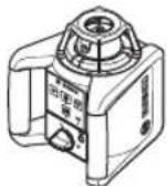
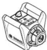
Xopn30HTaHNO nOIOKHe He BepTKaHNO nOIOKeHne IocTaBe H3MepBaTeHnHa ypeBbpy CTa6HnHa OCHOBAB XOpN30HTaHNO HnBepTKaHNO nOIOKeHne,MOHTnpaTe Ro BbpyxCTaTHBa (38) HnBbpxy Dbpxka 3a CteHa (42)c H3paBHnTeHnMoDyI.
Iopadn roJrMaTAtouHocHa n3MepBaTeHNHa ypeD peaHnpa H3KIOUHTeHNOyBCTBNTeHNO Ha B6paunu npOMHa HnoJoxKeHHeTO.3aTOBa BHIMaBaHTe Da rO nocTabte CTabHNo, 3a Da n36erHete pekbcBaHe Ha pa60ta 3a DOnbHnTeHHO HNBENIPAhe.
BknIOuBaHe n H3KnIOuBaHe
3a BkIouBaHe Ha n3MepBateHnHn ypeHnatChTe NyckoBn npekcbcay4).BCNKn HnDnKaTopn CBETBa 3a KpaTko. N3MepBateHnHnYpeH n3PnPaA npOMeHNBnna3apeH mbu6) HOTBeCa Harope (9) OTxOxDnTe OTbOpn (8).
He haooubaTe na3epHnHa b4 KbM Xopa Hnn KHBOTn; He rnaTe cpeuy napeHnHa b4,cbuHO TOrnAmo pa3ctOaHHe.
H3mepBaTeHNHTyepe3aNoyBaBeHaraCABTOMaTHOHO HnBEnIpaHe. IIO BpeMe HA HnBEnIpaHETo CTATyCHATA HnDnKaun (3) Mnra B 3eNeHo, Na3epbT He Ce BbPTN mMra. H3mepBaTeHNHTyepeE HnBEnIpaH Korato CTATyCHATA HnDnKaun (3) CBeTN B 3eNeHO Ha3epbCTCBt. CneJ npNKIIOUbaHe HA HnBEnIpaHETo H3mepBaTeHNHTyepeCTapTnpa ABTomatNUHO BPOtauHOH peKIM.
He octabTte ypeDa BkIIOueH 6e3 HAp3Op; CneKato npHKIOUHTe pa6Ota, ro N3KIOUBAHTe. DpyrNnua Mo- rata 6bDat 3acnenen OTO na3epnna b4.
C 6byToHa 3a potaioHOHepeKIM (5) pecn. 6byToHa 3a HInHeepeKIM (11) MoKeTe Oue No BpeMe Ha HINBEnIpaHE To Da YcTaHOBtpe KIMHa paBoTa. B To3n CnyuH N3MepBaTeHNrT yPeD CTapTnpa CneD npNKIOUbaHe Ha HINBEnIpaHEo B H36paHHpeKIM Ha paBoTa.
3a H3KIIIOUBAHe Ha H3MepBaTeHNHn ypeI HaTHcHETe OTHOBO nyCKOBn npeKbcBau (4).
H3MepBaTeHNHTypeCnKIOUBAABTOMaTHO 3aAHTaHa6aTePHTe,peCn.akymyTAOpHTe 6aTePHN,ako 3a NOBe
ye ot 2 he H3BbH dHaana30Ha Ha cAmOHbENHPaHe nn npeDynpexdHneto 3a yAp e aKTHBnPaHO 3a NOBeue ot 2 h. IOn3NIOHnPaTe N3MepBaTeHNH ypeD haHOBO I RO BKIOUOte OTHOBO.
Pa6oTHnpeXmm
0630pHa pexHMnTe Ha pa6oTa
BcHKn 3 pa60THn peKHMa Ca Bb3MOKH N XOpH3OHTaJIHO H BePTKkaIHO NOIOKeHHe Ha N3MepBaTeHNH ypeI.
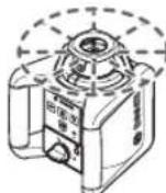
Potaunohnepekm
PotaunOHnHT peXHM e Oco6eNo npenopbHrTeHepn H3noN3BaHe Ha na3epHHnphemHK. MoKTe Da H3bnpaPe p3nnHcCKOpOCTn Ha BbptHe.
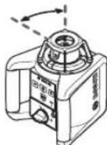
JInHeeHpeXHM
BTo3npa6oTeHpeXmIpomeHnBnTnla3epeHbUcDBNXN BOrpauHueh bTbHaOTBaPnE.Taka cNoDopRaBVIMocTaHa na3ePHnIbUcPabHeHneCpoatauHOHHpeXm.Moxete da perynPate bTbNa Ha pa3xOIMocCT Ha na3ePHnIbU.
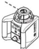
ToykoBpeXHM
BTo3n pa6oTeH pexHM ce noCTnHa HauD6paTa BUNMOCT Ha npOMEHINBnaNa3epeHbU.ToCnyKHaNp.3a necho npedaBaHe Ha BnCOuHHn 3a npOBepKa Ha pa3MNHaBaHn.
HINHeHHNHTUToKOBnHTpeKMHeCaNoDxOJaUN3aH3non- 3BaHe C Na3epHNn PnneMHNK (36).

PotaHoneH peKHM
CneB BCAKO BKIOUBAHe H3MEpBaTeINHHTypeDceHAMIPA B potaHOHEPexHM CbC CTaHdAPTHa potaHOHHa CKOPoCT (300 min-1).
3a CMHa OT IINHeeH KbM potaunohen pexHM HATNCHEte 6yTOHa 3a potaunohen pexHM (5) INH 6yToHa 3a potaunohenpexHM (26) Bbpxy DnCTaHUNOHHO ynpabNeHne.
3a npomraHa HCOKOCTTHa BbPteHe HaTNCkaTe 6yToHa 3a potauHOH peXHM (5) nIN 6yTOHa 3a potaHOH peXHM (26) Ha DCtAHHoHHOT ynpabNeHne DOkato XeNa-Hata CKOPCT He ce DoCTnHE.
Pn pa6oTa c nasepHn npemHnK Tpa6Ba da yctahOBHe Hau-BnCOKaTc CKOpOCT Ha BbptHe. Pn pa6oTa 6e3 naepHn npemHnK 3a No-do6pa BnHmocT Ha naepHnR bUHaMaIeTe cKOpOCTHa BbptHe N3non3BaTe naepHn OuHa (46).

HHeeH pexHM/ToUcKOBpeXMM
HaTnCHeTe 3a CMnA B IINIHeH peKHM,peCn. TOUkOB peKHM 6byToHa 3aIINIHeH peKHM (11)nnb6yToHa 3aIINIHeH peKHM (27) Ha nCTaHcNHOHHoY npaBneHne.
I3MepBaTeHnHrTypeI npemHaBA BIIHeeH pexmC HaimKna bTbHa HO TBapAhe.
3a npomraHa ha bIbIa Ha OTBaprHe HaTnckaTe 6yToHa 3a IHHeH pexm (11) nIIb6yToHa 3a IINIeH epeKIM (27) HdNCTaHIOHOHOTynpAbeHHe DOKATO JekAHNA pa6oTeH peKIM He Ce DoCTHRe. bIbIbT Ha OTBaprHe CE yBeJIuBa NocTeEH NoPn BCaKO HaTnCKaHe, eDHOBpeMeHNo C TOBa CKoPoCTTa Ha BbPteHe CE yBeJIuCABa PnP BCaKa CTenEH.
Cnei Han-TolemnO TBP Ho OTBapRHe N3MepBaTeHnHrT yPeI npemHHaba CNeI KpaTbK DoNTbHnHTeJeH XoD B TOcKOB pexm. POBtOpHo HATNCKaHe Ha 6yToHa 3a NHeeh pexm (11) OTBExJa ObaTHo KbM NHeHnHrpeXm C hA-MaIKN bTbN Ho OTBapRHe.
Yka3aHne: Iopadn Hnepueta Na3epbT MoKe neKo da n3nn- 3a N3BbN KpaHnTe TOcKn Ha na3epHaTa nnHna.
Функци

3aBbptHa Ha HINH/ToKa Ipn XOpH3oHTaHIO He BpaMKHTe Ha paBHnHaTa Ha BbpTeHe (A)
PnXOpH30HTaJIHO nONOKeHHe Ha N3MepBaTeHnHa ype MoKte Da No3NIOHnPaTe Na3epHaTa NINHn, pecn. Na3epHaTo4ka B paMKite Ha potaioHHata paBHnHa Ha na3epa. BbPTeHETo e Bb3MOxHo Ha 360^
3a ceta 3abptete KOChTe 3a Bbptte (10) Ha pbka B JekanaHATA NO3nUIN HN N3NO3BaIe DnCTAHNOHHOTO ynpabHe:HaTNChe 3a 3aBpTaHE No YacOBHnKa 6yToHa BbPte He No YacOBHnKa (29) HA nCTAHnOHHO ynpabHe, 3a 3aBbPaThe 6paTHo HA YacOBHnKa HtncHe 6yToHa BbPte He ObaTHo HA YacOBHnKa (30) HA nCTAHnOHTO ynpabHe. Ppi potaHonepeXHM HaNTCKaHTo Ha 6yToHNrTe Hma eFekt.

3aBbPTaHe Ha poTaunOHHa paBHnHa npH Hno nOIOXeHHe (Bx. qnr. B)
ПпВЕТИКАЛН NOLOЖЕНИЕHA N3МЕРВATELENHNY UyepeMOKTeДа 3aBbPNTe J3ePHaTToUka, J3ePHaTAnHINHINPOtaUHOHATApaBHHa3aJIecHO N3MeCTBaHE INIINapAENHO HINBENIPAHE BdHaNa3OHOT ± 8% OKONO BEPTIKANHATAc.
3a3aBpTaHe no yacOBnKa HATncHete 6yToHa BbptHeNo yacOBnKa (29) Bbpxy DnCTaHOnHHoTO ynpaBneHne.
3a 3aBbPtahe 6paTHo Ha yacOBHnka HATNCHE 6yToHa BbPtHe 6paTHo Ha yacOBHnka (30) Bbpxu nctaHnHOto ynpablenHe.
ABTomatnHnBennpahe
06u nprrne
N3MepBaTeHnHrT ypeI pa3no3HaBa caMoCToTeHNO xOpH3OHTaHNO, pecn. BepTHKaHNO nOLOXKeHne. 3a CmHa MeKdy XOpH3OHTaHNO H BepTHKaHNO NIOXKeHne N3KlIOUeTe N3-MepBaTeHnHrypeI, P03uHOHpaTe rHOHO rBO BKIOUeTe OTHBO.
CneB BKIOUBaHe N3MEpBaTeHnIypeI npOBePBAxOpH2OHTaHaTa,peCn.BepTKaHaTaNo3uNIGKOMNEHCnpa
aBTOMaTHUHO HepaBHOCTHe BpaMKHe HaIHaNA3OHa 3a CaMOCToTeHNO HbENHPaHe O Tnp6n. ±8% (±4,6°).
IIO BpemeHa HnBEniHpaHETO CTaTcHATA INHnKaun(3)MnRaB 3eNEHO,na3epbHT He Ce BbpTH Mnra.
H3mepBaTeHNHHTypee HNBEnnpaH KOrato cTatcHata HnDnKaua(3)CBETN B3eNEHO Nna3epbCTCBt. CneI npKJIIOUbaHe Ha HNBEnpHaHTo H3MepBaTeHNHHTypee CTapTnpa ABTomATuHO BPOtaNOHeHpeKM
Ako n3MepBaTeHnHrT ypeD CneD BKIIIOUbHe HIN CneD npO mHa B NOIooKeHnEo hAKnIOHeH Ha NOBeue ot 8 %, HNBENpaHTo Beue He e Bb3MOxHo. B To3N CnyaH potOpBt CnpHa, Na3epbT MIRa H CTAtyChATA HNHNKauZna (3) CBETN B UcpBeHO. PpomeHete No3nHra Ta H3MepBaTeHnHrypeD H3uKaaiTe aBTOMATNUHOTO My HNBenPae. Be3 HOBO No3nHOnHpaHe cNeD 2 min Na3epbT H CneD 2 h n3MepBaTeHnHrypeD ce n3KlIOUbAT ABTomATNuHO.
Korato n3MepBaTeHnHrYpeEd CE HNBEnIpaH ABTOMaTHuHO, TOI CNeIg NocToRHaXOpN3OHTaHIO CT,peCn.BePTrKaIHO NOJOKeHHe. PpH pOMraHa NoNOnKeHHeTo ABTOMaTHuHO Ce n3BbPbBa NOBtOPHo HNBEnIpaHe. 3a n36aRbAe Ha NorpeShn n3MepBaHnNo BpEme Ha HNBEnIpaHeto potOpbT CnPa,na3epbT MraH CTatYChATA HNDnKaua (3) MrraB 3eneHO.

PpOBepKa 3a ToHocT Ha H3MepeTHeHpyeI
ΦaKTOpH, BnHReuHa ToUHOCTTa
HaI-TOrIaMo BnHHe NBe BpXy ToUHocTt HMa OKOnHata TempeIpaTypa.CneuaHNo TEMepaTpHata pa3Nka OToNda Harope MoKeJa PpeIN3BnKa OTKIOHeHn HaJia3epHnIb4.
Tbkyato TemnepaTyPhNte pa3nKnCa hai-cnHnB 6n30ctdo noda, npa pa3ctOraHHna HAD 20 m Tp8Ba 3aDyJXHTeHOnda MOHTnpaTe H3MepBaTeHHna ypeHa CTaTHB.OCBeH ToBa npn Bb3MOxHcCT BnHaHn NOCTaBnTe H3MepBaTeHHna ypeB cpeData Ha pa6oTHata PNOU.
OTKIOHeHnraCTaBaT3abEnkMnHa pa3OTHNn, no-ToMe nO 20 m Ha pa3OTHNn O npAdbKa Ha 100 m Moat Da cTaHaT DbA Do YeTnp NbTu No-ToLEMN CnpMo OTKIOHeHneTo Ha 20 m.
HapeC BbHnHTe paKTOpN, npHuHa 3a otKIOHeHHa MoTa da 6bDat cbso n fakTopn, cBp3aHHc ypeDa (HaNP. NaDaHe nn CINHN Bn6paun/ynap). 3aTOBa BNHaHn ppei 3anObaHe Ha pa6ota npOBepBaTe TOOHCTTA Ha HnBeInipahe.
Ako npn HAKOONOTnpOBepKIne H3MepBaTeHnHT ypeN HAnxBpINMAKCHMaHNO DOnyCTHMOTO OTKNoHEHe,TOI Tpa6BaDa 6bDe peMOHTnpaH B OTOpHsPaH cepBn3 3a eNEKTponHCTpyMeHTn Ha Bosch.
PpOBepKa Ha ToUHocTHa HnHBenHpae npxOpH3OHTaIHO NOnOKeHHe
3a Hndexn H ToeypeyntpnoBepkata ce npenopbya dae Bbpy CBO6OHa OTceka OT 30 m Bbpy 3paBa OCHOBA nped cteha. N3BbpWete 3a DBeTE oN no eHa nbla npoueDypaNo hMepBaHe.
-MoHTnpaIte H3MEpBaTeHnHny ypeH na p3cTOnHne 30 m OT cTeHATA Bbpxy CTaHNB nHn FO NOCTaBete Bbpyx TBbpda paBaH noBbpxHOCT. BKIOUeTe H3MEpBaTeHnHny ypeD.
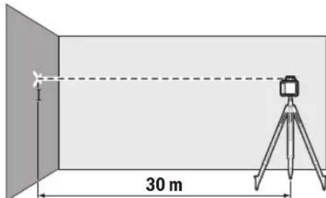
-MapKnpaTe CneI npNKIOUbaHe Ha HNBENpaHTo CpeDataHa Na3epHnHaBbBpxyCTeHata(TouKa I).

-3aBbptTe N3MepBaTeHnHa ypeHa 180°,6e3 da npomeHrte No3nHraMy. N3aKaHte ro Da ce HnBeHnpa HMapKnpaHTe CEHTbPa Ha Na3epHnlaBHa CTHeTata (TOka II).Pn TOBa Ce NoctapAte ToKa II da e NO Bb3MOxHOCT BEPTKALHO HAD,peCn. NOD TOKa I.
Pa3nkaTa d MeKdy DBeTe MapKnpaHn TOckn I n II Ha cTeHaT aDa JeCTBnENTHO TOKIOHeHne NO BNCOUnHa Ha N3MepBaTeHNr ypeD 3a H3MepeHata OC.
IbTopeI npoucea n3a npyraTc oc. 3a ceTt a npedn hauA IOTo Ha N3MepBaHETO 3aBbPTeTe N3MepBaTeHNHa ypei Ha 90^
Ha pa3cTOrHHeTo 3a H3MepeBaHe OTe 30 m MaKcHMaJIHo DoNpyCTMOTO OKJIIOHeHHe Bb3JIH3a Ha:
30m×±0,1mm/m=±3mm.Pa3nKATA d Mekny ToKneI I II pRn BCaKO OT DBeTe H3MePBAHn MOKe Da Bb3N3a MaK-CnMym Ha 6 mm.
Yka3aHn 3a pa60Ta
BHHarn MapKpaIte cIeHbpa Ha na3epHata toka, pecn. Ha na3epHata nnHna. C pa3ctoHneTO rolemHaTa Ha na3epHata toka, pecn. Ha na3epHata nnHna ce npomehra.
Pa6ora cnaepnata MepeHTeHa nnoa (Bx. fhr.C)
Ia3epHATA MePHTeHa IIOUa (47) noOobpBA BnIMoCTTa H aIa3epHNA Ib4 npn He6naTnpnTHn pa60THn ycNOBn nno-ronm pa3cTOnHH.
Otpa3Baata NoBbpxHocT Ha Ia3epHaTa MepntHa nnocha (47) noo6pba BnuHmocTt Ha Ia3epHaTa IHHn, a npes 10p3paHATA NOBbpxHOCT Ia3epHaTa IHHN MOKe da ce BnH n OT o6paTHa CTpaHa Ha Ia3epHaTa MepntHa nnoya.
Pa6oTa cbc CTaTHB (PnHHaJIeXHocT)
H3noI3BaHeTo Ha cTaTHB OcHrypRa Cta6nH0,perynpyeMo NIO BnCOUHHa MOHTnpaHe Ha H3MepBaTeHNHa ypeD. NocTabeTe H3MepBaTeHNHa ypeD c 5/8" NocTabKaTa 3aCTaTHB (21) Bbpxy pe36ata Ha cTaTNBa (38).3aterHete H3-MepBaTeHNHa ypeD C BNHTa Ha cTaTNBa.
PnCtAaBcH3MePbTeHaCKana Bbpxy H3TeTnHETo MoKxTe Da HaCTpOaBaTe DnpeKTHo PnpEmctBaHTo Ha BnCOuHa.
Ipei Da BkIOUHTe I3MePbATEHnYyPe, HAcOHTe CtaTHBa rpy6o.
Pa6oTa Cdbpxka 3a cTeHa WM 4 (npHnHaIeXHoCt) (Bx.Φnr.D)
MooKTe Da MOHTnPaTe H3MePBATeHnIypeI N BbPx dyBpKaay 3a CteHa C n3paBHNTeH moyn (42). 3a cenTa 3abNITE 5/8" BnHT (44) Ha DpbKaya 3a CteHa B NoCTabkata 3a CTaTHB (21) Bbpx H3MePBATeHnIypeI.
MOHTAX Bbpy CteHa: MOHTaKbT Bbpy CteHa ce npeno-pbya HAp. pni DeHocTH, KOHO Ca HAD BnCOUHaTa Ha 3-KapBaHe Ha ctaBnTE nPi DeHocTH Bbpy HeCTaBnHa NOBbpxHOCT N6e3 CTaHB.
3aBHTe DpKya 3a CTeHa (42) C BHTObe npe3 OTBOpHe 3a 3aKpenBaHe (40) KbM CTeHa Hn Cbc 3aKpenBaun HA (39) Bbpxy NaCTHa. MoHTnpaTe DpKya 3a CTeHa No Bb3MOXHOCT OTBECHO BpXy CTeHa N BHIMaBAte 3a CTa6HIN HO 3aKpenBaHe.
MOHTAX Bbpxy ctaHB: Moxete da 3aBnete bpxa 3a CTHeA (42) n C NoCTaBA k 3a CTaNB (41) OT 3aHaT a TpaHa Bbpyx ctaNB. ToBa 3akpenBaH e oco6eHo npenopbHTEN HO pnp DeHocTH, pnp KOnTO potaunOHATA paBHnHa Tp8Ba Da CE HacOuN KbM pepepeHTHa IHHN.
C NOMOHTaHaH3paBHTENHHMOyI M0xTe Da H3MeCTBaTe MOHTpAHN H3MepBATeNeH ypeD OTBeCHO (PnH MoHTax Bbpxy CteHa), pecn. BODopABHO (PnH MoHTax Bbpxy CtaTHB) B DnAan3oH OTK.16 cm. 3a cTeta pa3BnTE BnHTa (43) Bbpxy H3paBHTENHH MOyI, H3MeCTe H3MEpBATeHHYpeB JKeNaHATA No3uINI N 3aTeHHe TE OTHOB BVHTa (43).
Pa6oTa c na3epHHn npHemHnK (npHnHaIeXHoCT)
3a no-do6po oKpmbaHe Ha na3epHnTe nHH npn He6naorponPnTHn CBtINHH yCNOBn (CBeTna CpeDa, HenocpeCTBeHN CbHyeBn bHn) Hn RaONm pa3CTOHRn H3non3BaTe na3epHn npneMHNK (36).
Pn potaohnnna3epn c hKoJIko peXHMa ha pa6ota H-6bepeTe xOpH3OHTaIeH NII BepTKaIeH peXHcM C MaKcHMaHa ckopocT Ha BbTeHe.
3a pa6oTa c Na3epHnI npHeMHNk npOeTe H cna3BaIte HeROBata HHCTpyKUra 3eKcNlloatau.
Pa6ota c dnctahnHOHHTO ynpaBHeHne
PnHaNTCKaHe Ha KOnyEtTa 3a ynpaBHeHne H3MepeBATEHnHType MoKeJa ce pa3HNBeNIPA, TaKa Ye BbPTeHTo 3aKpATko Da CnpE. Upe3 H3NON3BaHeto Ha DnCTaHcNoHHOTo ynpaBHeHne To3n eFekT Ce n36rBA.
Cen3OpHTe(7)3aIINCTaHcHONHOTo ynpaBHeHne ce HAMnPaT OT TpN CTpaHN Ha N3MePbATEHnY ypeD, HapeD C DpyrTO H NaI NOJeTO 3a YnpaBHeHne OT npeHaTaCTpaHa.
Pa60THcH3MepBaTeJIHaJIeTBA(PpHHaIeXHocT) (Bx.Φn.r.E)
3a npOBepKa Ha HepaBHOCTn HnHaHacHe Ha HAcNOH ce npenOpbUa H3noI3BaHeTo Ha 3MePbAteHHaTa neTba (37) 3aeHNo C Na3ePHNn PnEMHNK.
Bbpxy n3MepBateHATA netBa (37) otrope e haheceHa oTHoCtEnHa n3MepBateHncaIa. HynBaTa BnCOUHa MoKeTe Da yCTAHOBITE C n3MeCTBaHe HaOnHn Kpa. TaKa HeNOCpeCDBeHO Morat Da 6bDat OTHTA Hn OTKIOHEHn OT HoMHnHaHTa BnCOUHa.
OuHa 3a Ha6nDaBaHe Ha Na3epHn8 nBc (npHnAdnEckoct)
OuHnata 3a Ha6HnDaBaHe Ha Na3epHHnIbUy FnITpHpaT OKoHnHaTa CBeTIHa. TaKa Na3epHHnIbUcCTaBnNo-NEcHOp a3nHm.
He n3non3BaIte na3epHnte ouHna (npnHaadNkHOCT) KATO 3aunTHn OUHna. Na3epHnte ouHna cnykat 3a noD6po pa3no3HaBaHe Ha na3epHnIb4; Te He npedna3Bat OT na3epHo IbueHne.
He n3noI3BaIte na3epHnTe ouHna (npHHaIeXhoCT)
KATO CbHueBn Ounna Hnn npn WoOpnpahe. Na3epHnte Oounha He npednarat nHa UV 3aunHa n HaamraBt Bb3npHeMaHTo Ha CBetOBete.
Ppimepn
Ppehahe/npoBepkaHa BncoounHa(Bx.ΦHr.F)
IocBaTe HmepBaTeHnH ypeD B xOpH3oHTaHNO nOIOKeHneBbpx 3dpabaNobbpxHOCTnHr MOHTnpaTe BbpxCTaTHB (38) (npHaNDeKHOCT).
Pa60ta c6c ctaTnB: NocTaBe H3MepBatEnHna ypeTaka, ye na3epHnrt Ib4 da e Ha JxenaHaTBA BOCOHNa. PpeHeceTe, pecn. npOBePeTe BHCQUHnTa BA JxenaHaTATOka.
DieHocn63 CTaTHB:YCTaHOBeTe pa3NkATA BbB BnCOuHNHe MeKdy na3epHHa bUy HBCOuHATA Ha pepepeHTHa ToUKCa NOMOHTA Ha na3epHa ueBa DbCKa (47).IpeHeceTe, pecn. npOBepTe n3MepeHa ta3NkBA BB BnCOuHNHe B XeJaHATA TOKA.
HnBennpane Ha oTBeca Harope npaenHo/HaHacHe Ha npabn brrn (Bk. qnr. G)
Ako Tp6Ba Da Ce HAnacrt npaBn BnNn da Ce HbEnnpat MeHHnHnCTeHN, Tp6Ba Da HbEnnpate OTBeca Harope (9) napaneHo, T.e. Ha CbIoTO pa3cTOrHne do pepepeHTHaTa nnHnna (HaNP. cTeHa).
3a cetaTnTOcTaBeTe H3MePbATEHnH ypeB BbB BepTNKaIHO nIOJKeHHe I TO IO3NtOHOHPaTe Taka, YeOTBeCbT Harope da npemHHaba NapalEnHo Ha pepepeHTHaTaNHHra.
H3mepete 3a TochOTO No3nOHHpaHe pa3cTOrHHeTo MeJy OTBeca HArope n pepepeHTHaTaNHHN DnpeKTHo Bbpxy N3-MepBaTeHHN yPeD c NOMOuTa Ha Na3epHATA ZeleBa Dbcka (47). H3mepete pa3cTOrHHeTO MeJy OTBeca HArope n pepepeHTHaTaNHHN OTHOBOCBb3MOxHO Ha-ToJMo p3cTOrHHeOT H3mepBaTeHHN yPeD. HnBeInpaTe OT Beca HArope Taka, ye da e Ha CbUTo PA3cTOrHHeOT pepepeHTHaTaNHHN, KaKTo I npn H3mepBaHeTo DnpeKTO Bbpxy H3mepBaTeHHN yPeD.
PpabnTbblKbMOTBeCaHarope(9)ce noka3Ba upe3 npoMeHHBna3epen6
Toka3BaHe Ha oTBecHa/BepTKKaHnPaBHHa (Bx.ΦmR.H)
3a MapKnpaHeTo Ha nepEnHnkyIpyHa, pecn. BepTKKaIIHa paBHnHa NoCTaBeTe N3MepBaTeHNHa ypeB BepTKaIIHO.Ako Tp8Ba BepTKaIIHaTa paBHnHa da npemHHaba NoD npab bTbN KbM pepepeHTHa IINHn (HaNP. cteHa), To HNBenipai Te OTBeCa HArope (9) KbMa3n pepepeHTHa IINHn.
OTBeCHATA paBnHa ce noka3Ba ype3 npomeHnBnaepeHn6.
HnBennpaHHeHaOTBeCHa/BepTHKaHApaBHnHa (Bx.Φnr.1)
3a da nopabHNTE npneHnkypHaTn aaepeHa Hnna potaunOHnTa paBHnca npaHmpepeHTHa TOkHa Ha CTHe, NOCTaBeTe H3MepBaTeHnHa yPeB BBB BepTKKaHNO NIOKHe HnOpaBHHe TnAepeHata HnHn, pecn. potaunOHHaTa paBHnHa cnpMa pepehTHATA TOkA. 3a TOHNo HnBeHnPaHe Do pepeeHTHa ToKA 3aBbptete PoTAUNOHnTa paB
HnHa OKoNo OTBeChHaTcOC (Bx. SaBpaHe Ha poTaunOHHaTa paBHnHa npBvePtnKaIHO nOIOKeHHe (Bx.Φn.B), CtpaHua 240).
Pa6oTa 6e3Ia3epen npHeMHNK (Bx.ΦHr.J)
Pn6IaIopnpTnCBeTIHHHycIOBna(HaNP.TbMHa pa6OtHa cpea)Ha Kbcn pa3cTOHHMOKeTe da pa6oTne 6e3
na3epHnI npHmHnK. 3a no-do6pa BnIMocT ha na3epHnI bHy n36peTe IInHeHa pa6Ota HnToKOBa pa6Ota H3aBbP-Te na3epHnI bY KbM ueBETO MACTO.
Pa60Ta c na3epeH npHeMnK (Bx. fHr.K)
3a no-d6p0 ha6nOdaBaHe Ha na3epHnI bIy npH He6naorponPnTHn CBtINHH yCIOBn (CBETna CpeDa, HENOCpeCTBeHN CbHueBn IuHn) nHa rOeMH pa3cTOnHH ce npenOpBuHA3no3BaHe Ha na3epHnI pnpemHnK (36).PiH pa6oTa cna3epHnI pnpemHnK H36peTe poTaunHOHe peKm C hA-BNcokata CKOPoCT Ha BbPTHe.
H3mePbaHe Ha roenemHa3cTOnHHa(BK.ΦnR.L)
PnH3MepBaHe Ha roJemn pa3cTOnHHa3epeHHr
PnpHmHK (36) TpAba Da ce H3noJIbBa 3a otKpnBaHe Ha na3eepHHN bUy. 3a HamaJIBaHe Ha CMyuBaAUTe BInHHn H3-
MePBateHHNtYpeD BnHaTr TpAba Da CE NOCTABB U cHTbpa
Ha pa6OHTa HOBbpXHOCT N Bpxy CTATNB.
DeHocTH Ha OTKPHTO (Bx. fhr.E)
HaOTKpHTO BnHArn TpR6Ba Da Ce H3NoI3Ba Na3epHHN npHEmHHK (36).
PnD DeHOCTHBbpxHeCTabHEnnoMOTnpaTe H3MepeTENHryepBbpxCTaTNB(38).Pa6oTeCaMoCAkTHBpaHaФyHKU3aIpEduPexKeHHeNEOTyap,3aJaH3eHerTe rpeHHNtMEpBaHnIprnDbHXKeHHHaNoDAHpa3KnaHnHaH3MePBeTENHyyepi.
IperneHa HndkaTopHe Ha potaunOHnnna3ep
| Лазерен
льч | Рotaцnia на
лazерни
льч | 3elenhoЧерб-
HO | 3elenhoЧерб-
HO | Черб-
HO |
| Въюоче Измерваленna урет (1 s самостая-
телен тест) | | | ●●● | | |
| Пъвонаално или постваши Нивениpane 2×/s o 2×/s | | | | | |
| Измерваленnaурет e Нивениpaneн/rotob за
разoting | ●●● | | | | |
| Диапазоньт на самоньениpane e превшиen 2×/s o ● | | | | | |
| Прededун探测енье рпс уydар akтувирано ● | | | | | |
| Прededун探测енье рпс уydар заideяствано 2×/s o 2×/s | | | | | |
| Нашенье bateория/akymалаторна bateорnia
za ≤ 2 h開放а | | | | | 2×/s |
| Актумалаторни ми обиknовени bateорий Ито-
шени | ○○● | | | | |
Service sculelectric
Strada Horia Macelariu Nr. 30-34, sector 1
013937 Bucuresti, Romania
Te.n.: +359(0)700 13667 (Блгарский)
ΦaKc: +40 212 331 313
Email: BoschServiceCenterBG@ro.bosch.com
www.bosch-pt.com/bg/bg/
Дугс сервиимадес се откpenete Ha:
www.bosch-pt.com/serviceaddresses
BpaKyBaHe

C orneon anaBaHe Ha OKoHnHa T cpea eneKtpueckntyepei,OBHKHOBeHnte HnAkyMnyatopHn 6ateHH,IObHLHTeHNHe pnpHaJNeXHoCTN OAnokBKeT Tp8Ba Da ce npedabat 3a onon-30TBopRaHe Ha cbDbPkaUHTe Ce BTRxCypobHn.

He n3XbpynIe enektpnueckhtyepeHn akyMylatopHnTe 6aTeHH/6aTeHHte npn 6HTOBnTe OTnaDbu!
Cama 3a ctpaHn ot EC:
CbINaCHO EbponeNcKaTaNpeKTHBa 2012/19/EC Beue Hn3non3Baemnte eeneKtpoypedn,a cbINaCHO EbponeNcKaTa NpeKTHBa 2006/66/EO deΦeKTHneHn n3pa3xOdbaHn
akymlaTOPH6aTeHH Tp8Ba da ce cb6npaT pa3dienHO n da ce npedaBt 3a ekONOrHNO peuKnInpaHe.
MaKeDoHcKn
БeЗб endocn HanomeH 3a poTaunckn Iacep N daLeuHHcKn ynpaByBaU

Ja ce npoHTaT n noHTyBaT cHTe ynatCTBa, 3a 6e30nacHO 6e36edHO pa6oTebe. AKe He ce cneDat OBHe ynatCTBa, HnterpnpAHTE 3aHTTHM MepKn
MOxKe da 6HdaT hapyuenn. HnKorau He n OwTeyBaJte npedynpeDyBaQHTe 3nau. IOBPO yBAJTE rN OBNE YIATCTBA N PPEADETE rN 3AEHDO CO IPOH3BOIDNTE.
BHHMaHHe -DOKKky KOpHCTNe Dpyr Hyei 3a noDecyBaBe HpaKyBaBe OcBeH OBDe HaBeDeHNTe HNNONHaKBn NocTaN,OBa MoKe Da DOBeDe Do OnaCha H3NoKeHoCt Ha 3paueHe.
MepHnOTypeCeHCnpauyBaCo03HaKa3a npEynpeyBaBe 3aIacepoT (O3NaeHo Ha pNkA3OT Ha MEPHnOTypeHa rpaФuKaTcTpHa).
Dokonky TeKcTHa 03HaKaTa 3a npEynpEyBaHe 3a nacepot He e Ha BaHnot ja3NK, Bp3 Hero 3anenete ja HanenHHcaTa Ha BaHnot ja3NK nped npBata ynotpe6a.
He npabete npomeHn Ha nacepcknotype.
He Hn KopHCTe NacepCKNte 3aHTTNH OUHna (doONHHTENHa ONPema) Kako 3aHTTNH OUHna. NacepCKNte 3aHTTNH OUYNa cnyKAT 3a noD6po paCIO3HaBaHe Ha NacepCKNt 3paK; cenak, Tne He WHTiTat OD NacepCKTO 3paueHe.
He rKopnCTeIacepcknte3aHTTHOcHna (DononHnTeHa onpeMa) kako ouHna 3a coHce Hn naK Bo coo6paKaJot. Iacepcknte ouHna He daBaat cenocha UV-3aHTTa nTo HaMaanyBaat npepno3HaBaheTo Ha 60n.
PpOHNBOJNTe CMeE Da Hn NopPbA CaMo KBaHnΦKUyBaN CTpyuH NepcoHaN CaMo CO opHnHaHnPe3epBn HnOBn. CaMo Ha Toj Haunn Ke 6nTe cIpyn BO 6e36eHocTa.
He n octabajte deaTa da ro KophcTat nacepckhot Mepeh ypei 6e3 Haid3op. Be3 Haid3op, Tne Moke da 3aclenat dpyrHnua.
He pa6oTe BO OKONHn Kaede noCTOn onaCHOCT OekCnNo3nJa, Kaede HMa 3anaNNB TeHOCTH, rac HnnpaHHa. Ce co3daBaat NcKPN, KOH MOKe Da ja Ja 3anaanat npabTa nn Napeata.
DOnonHHTeHH 6e36eHocnHaNoMeHH 3a GRL 250 HV:

He ro hacouybajte nacepcknot 3pak KOH nua Hn JxnbOTn Hemojte H Bne camnte da rnaTe BO dnpkeTknot nnn pefnekhtpaKnot nacepckn 3pak. Taka MoKe Da rN 3acJeNTe nUaTa, da npednBkate HecepeKn nn da n OWTETNE OHTe.
Dokonky nacepcknot 3pak Docnee do ouhte, Behdau Tpe6a da th 3aTBOPHTe H da ja TprHete rnaBata od nacepcknot 3pak.
IOnonHnten6e36eHocnHaNoMeHH 3a GRL 300 HV, GRL 300 HVG:
OTBOPHTe 3a nacepOT ce 03hauehn co haneHHua 3a npedynpdyBahe ha MEPHnot ypeD. BHMabajte HNBHATA no3HnJa npH KopNCteBe Ha MEPHnot ypeD.
Dokonky TeKcTHa COoBETHata HaneHHua 3a npdynpdyBaHe He e Ha BaHOT ja3NK, Bp3 Hero 3anene ja HaneHHuaTa Ha BaHOT ja3NK npd npba ynotpe6a.
PnKopHCTeHbetoHaNacepCoKnacaHaNacep3R, 6oBpHeTe BHHMaHHe Ha MoXHnTe HauHOHaHN npOnHCn. HEnpIpxyBaHTo KOH Obne npOnHCn MoKe DaIOBeDe IO NobpeHn.
MepHnOt ypeMoXe da ce KopHcTH OJNua, KOH 3HaAT paKyBaat co NaacepckHypeNi. Cnopei EN 60825-1 M. d. cnaF a3HaeBeto 3a 6nOLOIKOTO JeCTBO Ha Nacepot Ha OHTe N KOKata, KAKo H npaBnHata yNotpe6a Ha Naacepcka 3aunTtA 3a n36erHyBaHe Ha onaCHOCTN.
O3hauteTo noneto,kaede Ke ce Kopncn MephnoTypei,co cooDBeTHn HaneHHn 3a npedypeyBaBe 3a nacepot. Ha toj haunHKe n36erHete, Heno3HaHTe Iua da ce np6nKATdo onacnTe 30HN.
He ro cknadnpajre ro MEPHNOrypeHaMeCTaKaede HMaat npnctan HeOBNaCTeHN Nua. NuaTata kon He ce 3ano3Haehn CO KOpNCteBeTo Ha MEPHNOrype, MoKe da cn HauTeTat Ce6e Cn Ha Dpyrnte.

He ro hacooybajte Iacepcknot 3paK KOHnua Hnn XNBOTHn Hne NOrIeHybajte BO hero. Oboj Mepeh ypeD co3daBa Iacepckn 3paun od KnaCATA Ha nacep 3R cnopeq EN 60825-1. DnpeKeTEN pOrIe BO nacepcknot 3paK - IOd rOJema OndaneueheOCT-MoKe da Tn OOTET OUYTE.
PnHexe ce, noneto Ha nacepckoto 3pauehe da 6HeHaadrneyBaHO Hn 3aHTNEo. Co orpaHnuBaHe Ha nacepckTo 3pauehe Ha KOHTponpaHn POnHbKe Hn H36erHete OwTeYBaHata Ha OHTe HA HeOBNaCTeHNTe Nua.
MepHnO tyepeKorAaNoCTaByBaJTe ro,taKaIto nacepcknte 3paun Ke nomHybaat DoCTa Norope HnnoDony od BnCnHaTa Ha OHTe. Ha toj hauHH Ke 6nDete cnryPHN,NeKa HeMa da ce OWTEN OKOTO.
M36erHete rpeoekcnte od nacepcknot 3paKaHa Ma3HH NOBpUHH KAKO Ha np. np03Op Hn OrneDana.
OHTetyBaHeto Ha OHTe e BO3MOXHO H OPeΦnEeTnApaKn Iacepckn 3paK.
Dpyr6e36eHochn HanomeHH
He ynoTpe6yBaJte ONnUKN HnCTpyMeHTn 3a co6npaHbe KaKo DBOrNeI Hnn nyna 3a Ha6bByDaBaBe Ha N3BOpOT Ha 3paueHe. Co Toa MoKe da I n OwTeHTne BaWnte Ouy.
He ja npnhecybajte MarheThata onpema BO 6nn3nHa ha nmmnantn nn npytn Meunncn ypeHn,Ha np. nejcmejkepn Hn Hcynhcka npma. Marhtte Ha onpemata co3daBaat none KOe moKe da ja hapuHa cyHKJJaTa Ha nMnlaHTTe Hn Ha MeDnHCKHTe ypeHn.
Marhehata onpeMa dpKte ja noaneky od MarHeTCKH HocauHa noaTOUH ypeu CyBHTENnHa Marhet. Iopadn BnjuHnTo Ha MaHrTeT Ha onpeMaTa MoKe da JoJe Do HenoBpaTHo rybeHe Ha noaTOUte.
He n otbopajte 6atepHnTe. Nocton onaCHoCT OJ KpaTOK cnoj.
PnOwTeYBaBe HHeHponncHa yNoTpe6a Ha 6aTepnjata MoKe Da H3ne3e NaPea. Batepnjata MoKe Da ce 3anannn da ekcnnoDnpa.Bhece TcBex BO3dyx N DOKoKy HMa NOBpeHn OndecTe Hn HaNekap. PapeTa MoKe Da Hn HApa3HN DmHHTe NaHtTa.
Pn norpseHNO KOpHCTeHe Hn npn OWTetHa 6aTepnja MoKe Da NcTeue 3anaHbA TeHOC T od 6aTepnjata. H36erHyBaJte KOtAKT CO Hea. DOKONky Cnyuajno DojTe BO KOtAKT CO TeUHOCTa, HCnnaKhete Co BOa. DOKONky TeHocTa DOJe BO KOHTAKT CO OUYTE, NObapaje NEkapca NOMoi. IcTeueHATA TeUHOCT OD 6aTepnjata MoKe Da npeHn3BnKa KOKHN INPTaunnn Hn H3ropeHn.
BaTepejata MoKe Da ce oWTeH on ocTpHe npedMeTH KaKo Ha Np. KInnHcN HIN OdBpyBaHn CO HaBopeHNO BnJahne. MoKe Da doJJe Do BHaTpeWeH KpaTOK cNoj n BaTepejata MoKe Da ce 3aapan, da nyTuH qad, da ekcnnoipa Hn da ce pnerpee.
Heynotpe6eHata 6atepHa dpKte ja noDaneky od KaHcENapnck CnojyBaNKn, KnyeBHN, Keene3HH napn, KNNHUN, 3ABPTKN HIN DpyrMaH MeTANH PpeMETH, UTO MOKe Da npEIN3BnKaAT NPMoCTyBaHe Ha KOHTAKTHTE. KpaTOK cnoj MEr y KOHTAKTHe Ha batepHaTa MoKe Da npeIN3BnKA HrOpeHnH INI NOxap.
Kophtete ja Bosch-6atepujata cmo BO npOn3BouH Od npOn3BOOHTeOT. Cmo Ha ToJ NaHH 6atepujata Ke ce 3aHTTN oD ONACHO PpeONTOBapyBaHe.
HanoHete ja Bosch-6atepujata camo co nOpauaHte nonHaun.

3aHTTe r6bATEPnTe oTOnnHa,Ha np. OoDIOIroTpajHO H3IOKyBaBe Ha COHcEBn 3paU,OrAH,HeHCToTHN,BOa H BnRa. INaKy,NoCTOn OnaCHOCT OekCnIO3nJa n KpaTOk Cnoj.
БeЗбeнocн haNoMeHn 3a noHauch

Ipoountajte rH CHTe 6e36eHNOCH HANOMEH n ynaTcBA. IpeuKHe HactaHaTH KaKO pe3yNTa od HenpNDpKByBaBe Do 6e36eHNOCHHTe HANOMEH n yNaTcBA MOKe Da
npedn3BnKaaTeIeKtpuueH yap, noXkap N/nnTseWKNOBpei.
UybaTe r6e36eHochnTe HAnOMeHH yNaTCTBa 3a KopHeBe H 3a BO HdHHHa.
Oboj noHaue He e npedBndeH 3a ynoTpe6a od deua n Hua co orpaHnueHH cH3uKN, cEH3OpHN Hm MeHTaHH cNooc6HocTH Hn CO HeIOBOHNO NCKyCTBO H 3HaEHe. Oboj noNaHc MoKe da ro KopncTaT deua Ha8 rOuHH Kako H Hua co orpaHnueHH cH3uKN, cEH3OpHN MeHTaHH cNooc6HocTH Hn CO HeIOBOHNO NCKyCTBO H 3HaEHe, DOKoIKy Ce NOd HA3Op OD Hua ODROBOPHN 3a HNBHaTA 6e36eHocT Hn Ce NoDyuHn 3a 6e36eHn paKyBaBe co NoIHaUOT Hr pa3bnpaAT onachocHTte KOJ MOKe Da npOn3ne3at nopAHI Toa. Hnaky NoCTOn OnacHOCT OJ porpuHa yNtpe6a n NobpeiN.
3a BpeMe Ha KopHcTeHeTo, HcTeHbeto N OdpKByBaBeTo NaIeDyBajTe rN Deuata. Taka Ke ce OCHypate deKa deuTa HeMa da cn Irpaat co NoHauyot.
PonheTe cmo Bosch NiCd/NiMH 6aTePN co kanaunet od 9 Ah (2 6aTePnckn keHn). HanoHot ha 6aTePnja Mopa da oDrobap a Ha HanoHOT 3a nonHeBe Ha 6aTePnaja Ha nonHaOT. POnHeTe cmo 6aTePN 3a NobTOpHo
nonhe. Hnky noctOn onaCHOCT OndnojneKcnno3nja.
IpxkTe ro nonhaOT noJaNeKy od loxndnnn Bnara.HabneryBaHeto Ha BOda BO eNEKtpuHnot ypeI ro 3rOneMyBa pnsIKOT od eNEKtpuH yap.
HanoHete ro mepHnoT ypeD co nCnopaahHOT noHa.
OpjxBajte ja nCTOta Ha nonHaOT. IOKONky ce H3BaIka, NOCTOn ONaCHOCT OeNEKTPnueH yap.
Ppe cekoe KopncTehe, npOBepetre Hn nonHaOT, Ka6enot n npKnyokOT. He ro KopncTeTe nonHaOT, Dokonky 3a6eKHTe oWtetyBaHa. He ro OTbopajte camn nonHauOT n octabeTe ro Ha nonpaBA kaj KBaHnФkUyBaH cTpyeH nepcoHAn KoJ Ke KOPnCTn CAMO OPHHNHn pe3epBn DeNoBN. OwTeHnOt nonNau, Ka6en n npKnyok Ro 3rOleMyBa pNikOT 3a eNEKTPnuH yap.
He ro Kopnctete nonhaot ha necho 3anaHbna noDnora (Ha np. xaptnja, TeKCTNI HTH.) OHN. BO 3anaHbNA OKONHAA. Iocton onacnoct od noxap 3apaH 3aTOnnyBaHeto Ha ypeoT lTO npOn3neryBa npn nonHeBTo.
Onnc Ha npoH3B0DoT nepopmaHCnTe
BHHMabajte Ha cIHKnTe BO npeHnO T den Ha ynaTcBTo 3a KOpNCteHe.
YnOTpe6a co COoDBetHa HameHa
Potaunohen nacep
MepHnoT ypeE haMeHeT 3a OpeyBaHe n npOBepKa Ha TOUHN XOpN3OHTaHn BnCnHn, BepTKaHn LInHn, LInHn 3a H3paMHyBaHe n Nacepckn ToQKn. MepHnoT ypeE norOeH 3a KopncTeHe BO BHaTppeWeH n HAdBopeWeH npocToP.
DaneuHcNynpaByBaay
JaeneHHckNt ynpaByBaue HameHet 3a KOHTpOHa Bosch- potauHOH nacepn npeky Hnfopaepbena CBETnHa. JaeneHHckNt ynpaByBaue noroDeH 3a KopncTeBe BO BnatpeuH n aHBOpeuH npocTOp.
HnyctpaqnaHa KOMIOHEHTN
HymepnpaBeto Ha cInKnte CO KOMNHOHTn Ce OndecyBaHa npka3OT Ha MepHNOYpei N daJeHHCKNtO ynpaByBaH raPdNcKaTc TpaHua.
Potaunohnacep/nonha
(1)PnKa3aΦyHKuJa3a npeDnypeyBaHaBe 3a yIap
(2) Konque 3a npéynpéybahe 3a ydapn
(3)Пикада StaTус
(4) Konque 3a BknyBaHBe-ncknyBaHBe
(5) Konue 3a potaiohoen pexim
(6)Bapnja6nneHncepcck3paK
(7) Cen3op 3a daneyHnckn ynpabyBaay
(8)Излесенотьорза lacepcknot spak
(9) Touka Ha BepTnKaIaTaHa Rope
10) PotaunHa rnaBa
(11) Konque 3a nHHnck npexm
(12) PpeynpeyBaBe 3a 6atepujara
(13) NaKyBaHbe 6aTepeNn
(14) Iperpada 3a 6atepija
(15) Konque 3a 3aknyBahe Ha nperpadaTa Ha BaTepeHH
(16) Konue 3a 3aknyBaHbHe Ha naKyBaHbTe 6aTepeNn
(17) OTBOP 3a nonHebe
(18) PoiHaay
(19) Ctpyhen npnKnyoK Ha nonHaouT
(20) Pπκκλуκθεα πονηκθε
(21) PnDΦaT Ha cTaTHBOT 5/8"
(22) Cepnsckn 6poj
(23) Hattnc 3a npéynpèyBaHé Ha IacepoT
(24) PpeynpeyBaKn 3NaK Ha 3Ne3HNO TBOp Ha nacepot (GRL 300 HV/GRL 300 HVG)
A) NynctpnpaHATA HN OHnHaHApO npema He e den od cTaNdAPnOHo6e Hn HCnpopaka. Cenocchata Onpema MoKe da Ja hndete BO hawata Pporpama 3a npema.
DaneHHckn ynpaBybaa
(25)ДалачинсknуnpaByBaay
(26) Konje 3a poTaIHOHeH peXIM
(27) Konye 3a nHHckpeXIM
(28)KoNuepeceTnpaHbe3npeDynpEyaBaHbetoHa ydapn
(29) Konyu 3a BpTeHe BO npBaEu HA CTpeKnTe Ha YacOBHnKOT
(30) Konue 3a BpTeHBe BO npaBecnpoTINBEH Ha CTpeIKNTe Ha YacOBHNKOT
(31)Пикадзпренocнсгнан
(32)ИзлесенOTBOPЗИнфрацревнозразец.
(33) Cepnckn 6poj
(34)ФИКСИРаБЕHAKANAKOTODnperpaDATA3aBaTePIM
(35) Kanak ha nperepaada 3a 6aTepeHH
Onpema/pe3epBnIeNoBn
(36) Napecpckn npneMHNK
(37) Мерна netва
(38) CTAINB
(39) 3aBpTKa 3a npuBpcTyBaHbe Ha sNHNOT dpKAA
(40) OTBOPn3a npuBpCTyBaHbHe hSINHNOrDpaKaA
(41) 5 / 8^ -nphpaT3a cTaTHOBt HA sHINHO TApKAA
(42) SIneH npKau/epiHnua 3a n3paMHyBaHe
(43)3aBpTkHa ha eDHHuata 3a H3paMHyBaHbE
(44) 5 / 8^n -3aBPTKaHa sIHHNtOJpKaay
(45)MaHHeT
(46) Nacepckn 3aHTTHn OyIna
(47) Napecpa KaenHa Ta6na
(48) Kyφep
A) Nnyctppahata nn onnna hao npema He e den od cTaNapdHnot o6em Ha nCnpaka. Cenochata onpema moke da ja hajdete BO hawata Pporpama 3a onpema.
Texnukn noaToun
Potaunohnep GRL 250 HV GRL 300 HV GRL 300 HVG
| Бpoj на.dcн/артник | 3601K61 6..3601K61 5..3601K61 7.. |
| РавOTEN постор (разиус)A(B) | | | |
| -6e3 пасерский п riemнок okoly. 30 m 30 m 50 m | | | |
| - co пасерский п riemнок okoly. 0,5-125 m 0,5-150 m 0,5-150 m | | | |
| Точность на Новлиparable beA(C) | ±3 mm (при 30 m) | ±3 mm (при 30 m) ±3 mm (при 30 m) | |
| Точность полеса на салони велега范围内 ±8% (±4,6°) ±8% (±4,6°) ±8% (±4,6°) | | | |
| Точность врeme на Новлиparableе 15 s 15 s 15 s | | | |
| БрзINA на рotingaю 150/300/600 min | -1 | 150/300/600 min-1 | 150/300/600 min-1 |
| АгOL на OTВОр по линскк реким 10/25/50° | 10/25/50° | 10/25/50° | |
| Опетаиньда Temпера typа | -10°C ... +50°C | -10°C ... +50°C | 0°C ... +40°C |
| Temпера typа по скадиралье | -20°C ... +70°C | -20°C ... +70°C | -20°C ... +70°C |
| Мakc. опетаиньда висна пеку решенита висна | 2000 m | 2000 m | 2000 m |
| Мakc. релатиньда влажност на Возунот. | 90% | 90% | 90% |
| Стосян на Извалкеаност соред IEC 61010-1 | 2(D) | 2(D) | 2(D) |
| Клaca на пасер | 2 | 3R | 3R |
248|MaKeJoHcKn
Potaonen nacep GRL 250 HV GRL 300 HV GRL 300 HVG
| Тип на ласер 635 nm, < 1 mW 635 nm, < 5 mW 532 nm, < 5 mW |
| Од_STаньаве 0,4 mrad (целочen | aron) | 0,4 mrad (целочen
aron) | 0,4 mrad (целочen
aron) |
| Хорионолен прифат застимBOT 5/8"–11 5/8"–11 5/8"–11 | | | |
| Батугин (NiMH) 2 × 1,2 V HR20 (D) | (9 Ah) | 2 × 1,2 V HR20 (D)
(9 Ah) | 2 × 1,2 V HR20 (D)
(9 Ah) |
| Бaтугин (алкални-мангански) 2 × 1,5 V LR20 (D) 2 × 1,5 V LR20 (D) 2 × 1,5 V LR20 (D) | | | |
| Текина согласно EPTA-Procedure 01:2014 1,8 kg 1,8 kg 1,8 kg | | | |
| Диеменни (должних ×шируни × висни) 190 × 180 × 170 mm 190 × 180 × 170 mm 190 × 180 × 170 mm 190 × 180 × 170 mm 190 × 180 × 170 mm | | | |
| Вид на заштита IP 54 (заштита od | прав и п rescаные на
вoda) | IP 54 (заштITA od
прав и п rescаные на
вoda) | IP 54 (заштITA od
прав и п rescаные на
вoda) |
A) kaj 25^
B) Pa60THOTO none MoKeJa Ce HamaHn nopAaH HeNoBONHa YcNoBa Ha OKoHaHtA (Ha np. dIpeKTHa hIOKeHOCT Ha cOnHeBn 3paH).
C) no donmknHa ocknTe
D)HactaHybaaTcMo HeCpOBoDNHBHeNCTOTnH,HONoBpeMeHo Ce OeKyBa InpBpeMeHa CIpOBoDNBOCTIpeHN3BnKaHa oKDohEn3aJia. Cepcknot 6poj (22) Ha cneuΦnKaunOHa TnOuKa cnYkn 3a jaChna HndHTnΦnKaunJa Ha BaNt Mepe ypeid.
| Полнач | CHNM1 |
| Броча на дулартукг | 2610 A15 290 |
| Влесен наочь | V~ 100-240 |
| Фразковцима на влесна наимзменчнаструja | Hz 50/60 |
| Из�件е наочь | V= 3 |
| Из�件е наструja | A 1,0 |
| Дозвole納а Temпература на батериjsда рп польны | °C 0...+40 |
| Вреши на польны | h 14 |
| Броча на сатериски кени | 2 |
| Номинален наочь (no сатериска кениja) | V= 1,2 |
| Текина согласно EPTA-Procedure 01:2014 | kg 0,12 |
| Клaca на заштета | ☐ /☐ |
| Далейнику уразьвач | RC 1 |
| Броча на дд/артукл | 3601 K69 9.. |
| РавOTно поleA) | 30 m |
| Опатиньни temпература | -10°C...+50°C |
| Temпература рри скадираве | -20°C...+70°C |
| Мас. оратиньни висна пеку peферентна висна | 2000 m |
| Мас. релатиньни влажност на Возduхот | 90 % |
| Стени на Изbankаност соред IEC 61010-1 | 2B) |
| Батерija | 1 × 1,5 V LR6 (AA) |
| Текина сordласно EPTA-Procedure 01:2014 | 0,07 |
A) Pa60THOTO NOLE MOKE da CE HAMANI NOPAHN HENOBONH yCIOB H A OKOINHATA (Ha np. DnpeKTHa n3IOKeHocT Ha coHcEBN 3paun).
B) HacTaHyaBaTcMo HeCpOBoDnHB HeNcHcTOnH, Ho NOBpeMeHO Ce OeyKBya PnPBpeMeHa CnpoBODnBOCT PpeIN3BnKaHa oJ KOHdEh3aunJa. CepncknotbpoHa cneuKauhoHa TnOka (33) cnky3 a ja Cha hndtHnKaujHa BaHNOta daneuHcKn ynpaBvay.
MOHTaKa
HanojyBaBe co eheprnja ha daneyHHcknot ynpabByba
3a pa6oTeHTo co daJeHHckNOT ynpaByBaCe npenopayBa KopnCTeHe Ha anKaIHO-ManraHcKb 6atePHn.
3a OTbopaHe Ha KaIakOT od npepaDAta 3a 6atePHn (35)
PnITNCHEtHa KOnHTe 3a 3aKnlyyBaHe (34) BO npaBeu Ha CTpekata N3BaTeTo KAANOT OD npepaDAta 3a
6atePHn.CTabete ja 6atepNJata.
PiPTOa BHIMAbajTe Ha NoIOBte Cnopei npka3OT Ha
BHATpeHnA tCpHa OH npepaDAta 3a 6atePHn.
Dokonky He ro KopnCTHe daeneHHckHOT ynpaByBaH noDIORO BpeMe, n3BaTe r H 6atePnte. PnnoJIOr CKlaHpaBe BO daeneHHckHOT ynpaByBaH, 6atePnte MoKe Da KopoOHaPaAT N da CE hCnpa3HaT.
Cha6dyBaHbe co eheprnaHa MepeHnotype
MepHnoT ypeD moKe Da ce KOpHcTH Hn co 0bueHH 6aTePn Hn co Bosch-NAkyBaHe 6aTePn.
Pa6oTeHbe co nakyBaHe 6aTepeHH
BHMMabajte Ha eneKTPnHHot HanoHOT Ha H3BOPOT HA CTpya MOpa Da OJROBaHa HOOj KOJE HABeEH Ha CneuΦNkAunOHATA NIOUka HA NOHauOT.
HanoHHeTo ro nakyBaBeTo 6aTeepn (13) nped npBaTa yNoTpe6a. NaKyBaBeTo 6aTeepn MoKe da Ce HanoHn NCKnyuBO CO NOHaOT (18) npedBnEh 3a Taa HameHa. CTabete Ro ctpyJnHOT npNKlyuOK COOdBteH Ha BaJaTa ctpyjHa MPexka (19) BO NOHaHT (18) nOctabete Ro da ce BKNONH.
PnKnyokOT 3a nonHaOT (20) CTABETo BO OTBOPOT 3a nonHebe (17) BO nakyBaHeto 6atepn (13). PnKnyeTe rO nonHaOT Ha CtpyJHata Mpeka.
3a nonhebe ha npazno nakyBaBe 6atepn, notpe6n Bn ce okony 14 h. Pnonayot n nakyBaBeTo 6atepn ce 3aunTeHn od npenonhyBaHe.
HOBTO nakyBaBe 6atepnnnn NaKyBaHeTo 6atepnn 7to He e ynoTepeBvAno nOOnrO Bpeme, noNHaTa jaUnHa ja DOCTnHyBa No OKony 5 uKnLynC H noNHeBn npa3HeBe.
He ro nonhe t nakyBaHbTo 6aTePN (13) no cekoja ynoTpe6a, 6nnejKe ce haamH HerOBnOT KanaHTe. HanonHe r o naKyBaHbTo 6aTePN, dOKONky npdynpedyBaHbTo 3a 6aTepnjata (12) HnpeKnHato CBetn nn Tpenka.
3haujho ckpatehoto Bpeme Ha pa6ota no nonhebeTo nokkyba, deka 6atepnjata e notpoweHa Mopa da ce 3aMeH.
Pn npa3no nakyBaBe 6atepn, MEPnOt ypeJ moKe da ro KopnCTte Co nOmoU Ha noHaouT (18)doKoNkY toj e npKnLyueH hA cTpyJhaMpexa. NcknyeTe ro MEPnOt ypeJ H nonHeTe Ro nakyBaBeTo 6atepn Okony 10 min n NOBTOPO Bklyuete To MEPnOt ypeC o npKnLyeuH noHaay.
3a MeHyBaBe Ha NaKyBaHbTo 6aTePnN (13) CBPTe Tc KOnyTeo 3a 3aknyBaHe (16) BO No3njuJa HnBLeuTe Ro NaKyBaHbTe 6aTePnN Od MEPnHOT ypeI. BmTHeT e HOBO
nkyBaHe 6aTePNB O MePHNOT ypeN CBPTeTg KOuTeTo 3a3aknyBaHe (16) BO no3njuja
Dokonky He ro KopnCTHe MEPHOTypeNoONBpeMe,3BaTe Ro nakyBaBeTo 6aTePN. PnnoOnro cKnAnpaHe BO MEPHOType,6aTePNte MoKeJa KOpOHaat Hn da Ce Hcnpa3HaT.
Pa60ta co 6aTePnn
3a pa6oTa co MeHnOtypeI ce npenopayBa KOpncTeHe Ha anKaJIHO-MaHrAChKn BaTePnN.
3a Baede He Ha nperepaata 3a 6atepnn (14) cBpTeTe ro konueTo 3a 3aknyuBahe (15) BO nO3njuja .3BneueTe ja nperepaata 3a 6atepnn Od MepHnot ypei n CTabeTe rna 6atepnnte.
PnItoa BnMabajte Ha noIOBnTe Cnope npKa30Ha BHATeHATA CTpaHa OD npepaTa 3a 6atePHN.
Cekoraw 3amehybajte r n CHTe 6atepnn OeJHaW. Kopnctete camo 6atepnn OeJen npOn3BOJNTEN H COHCT KanaIET.
BmTeHETe ja nperepaada 3a 6atepn (14) BO mepnnot ype n CBPTeTo ro konqeto 3a 3aknyBahe (15) BO nooNjna
Dokonky He cTe ro KopHcTene MEPnOt ypeN nobEke Bpeme, n3BaTeTe r6bATEPnHTe Ond. akymnatopcknte 6aTEPHN OD MEPnOT ypeN. Pnp noJIOr CKlaIpaHe BO MEPnOt ypeN, 6aTEPHnte N akymnatopcknte 6aTEPHN MoKe Da KopoIpaAT N da ce Hcnpa3HaT.
Pnka3Ha cocto6a Ha HANONHeTOcT
ДokолуnpdunpydyaBaHeto 3a batepnjata (12) trpenka npBO uPBeHO, МернOT ypeM мождда paBOTu yUte 2 h.
Iokony pndynpeyBaBeTo 3a 6atepnjata (12)CBETN HepeHHato UpBeHo,He e Bo3MOxHO da Ce Bpuat MepeHa. MepHnotypeA BtOMaTcKne HcknyyBa no 1 min pa6ota.
Ynotpe6a
3aHTTeTe H MepHnOT aNAT H dAneHHckHot ynpaByBaO od Bnara H dIpeKTHo N3IOxYBaBe Ha coHcyBn 3pau.
He rHn3noKyBaJte MePnHOT ypeH n daneuHHckNt ynpabyBaH aekCTpemHn TemnepaTyHn
TeMnepaTyPhN ocunauuHa np. He n octabajte OJIOB Bpeme BO ABTOMObHOT. PnI rOJIeMHOCUNauuBO TeMnepaTpyata, OCTABeTe Ro MEPHnot ypeH N daJeHHckNt YnpaByBaH JApBBO Da ce akHMATn3HpaaT, ppe Da rH CTABHTe BO ynoTp6a. HanpaBete npOBepka 3a ToUHOCTa Cekoraaw npedJa npoDOnkIne Co paOta Co MEPHnot ypei (BnuN "KoHTpona Ha ToUHOCTa Ha MEPHnot ypeD", CtpaHnua 252).
PnEeKCTpeMHN TeMnepaTyPi NIn TeMnpaTyPhN OCunnau, npeun3HocTa Ha MePHNOypeJ MOKe da ce Hapyn.
H36erHyBaJte yapn nIpeBpyBaHa Ha MePHNOType. IocHHn HADBOpEshn BnJaHnJa Ha MePHNOType, nped Da ro ynotpe6nte 3a paOta, cekoraWn3BpWeTe KOHTPOna Ha ToUHOCTa (BnD ,KoHTPOna HaToUHOCTa Ha MePHNOType, CtpaHnca 252).
Ctabahe BO ynoTe6a Ha danueHHcknOt ynpabyBa
Co npntnckaHe Ha KOHTponHtte KOnuHa, MoKe Da ce NCKnyu HNBenpaHeto Ha MePHNOT ypeD, Taka ITO potaunjata 3anpu 3a Kpatko. Co npmeHa Ha daaneHHCKHOT ynpabyBa, OOBJ eEeKT ce n36erHyBa.
CeIIOEkaHMaIOBOJHO HANOH Bo 6aTepujata, daneuHHCKNOT UnpaBvBaue NOIqroTBEN 3a paBoTa.
MepnnoT ypeI noctabeTe ro Ha ToJ haun, Taka 1to CnHnHTe Ha daJeHHckNt YnpaByBaU Doceraat Do eHe Od ceH3OpHTe (7) BO dIpeKTe npaBeu. DOKONky daJeHHckNt YnpaByBaU He MoKe Da CE HAcOHN dIpeKTHo HA cEH3OpT, Ce HAmanyBa paobTHOTo NoPaueJe. Co pePfneKCHn Ha cIHANOT (Ha np. Ha SIOBHTe) DoMeTOT MOKe Da Ce NDo6pn In Pn INHdIpeKTe CnHAn.
I npntnckahe Ha eHNO oKoNHyBaTa Ha daJeuHcknOt ynpaByBa, CBetnata Ha npKa30 3a npHeoc Ha cnHa1 (31) nokkxyBaat DeKa e HcnpateH cHnHa1.
BknyBaHcToNckNyUbaHcToHaMepHnOypeHne MoKHO Co daneuHcknOY npaByBa.
CtabaBe Bo yIopTe6a Ha potaOnHnot Iacep
OdpKyBaJTe ro pa6oTHnOT npocTOp 6e3 npeukn KOH MoKeJa ro peFNeKTnPaat Hnn Nnonpeuat NacepckHot 3paK. Ha np., NOKpNJte rnppeFNeKTnPaayKHe Hnn cajHnTe NOBpHHn. He MepTe npeky CtaKneHn NaHEn HnCmUHN MaTePjAn. MoKe Da ce dobnjat NorpeHn Pe3yIaTH oN MepeHbTo npeky peFNeKTnPaayKn nn nonpeueh Nacepckn 3paK.
TocTaByBaHe Ha MePHNOTypeI
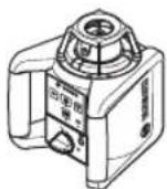
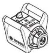
Xopn3oHTaHa nOIOx6a BepTnKaHa nOIOx6a
Iocabete ro MePHNOT ypeHa CTaBnHa NOJnora BO XOpH3OHTaHa H BepTtKaHa NIOX6a, MoTHnPajTe Ro Ha CTAHBOT (38) Hn Ha SdHnOT dpKau (42) Co eHNuata 3a n3paMHyBaHe.
Iopadn rolemata ToHocHa HNBenpaHe, MePHnoT ypei peaHnpa MHORYOCETNBO HAOTpeCNnIPOMEHn Hnooxbata. Ocnypajte ctabnHa no3uJa Ha MEPHNOt yepd, 3a da ce n36erHat npekHH Ha paobota npapd nnOONHTeHNO HNBenpaHe.
BknyBaBe/HcknyBaBe
3a BknyBahe Ha MePHNOTypeI npHTNCHe He KOnyTo 3a BknyuBaBe/HckNyUbae(4).CITE pNka3n KpaTko CBETHyBaAT. MePHNOTypeI ro NyUta BapNJabHNNOT NacepCKn 3pak (6) nTOkata HA BePTKanata HArope (9) on N3Ne3HNTe OTBOpH (8).
He ro hacouybajte 3paKOT CBETHnHa KOH Nnua Hnn XHBOTn H He nOrneHyBaJTe DnpeKTHO BO Hero, dypn Hn od ronema oDnaeneHoCT.
MepHnoT ype3aNoHyBa BeDnHaCo aBtOMaTcKo HNBenHpAbe.3a BpeMe Ha HNBenHpAbeTo, npNka30TaCTaTyC TpenKa (3) 3eNEHO, nacepot He potnpa HtpenKa.
MepHnoT ypeI e H3HbEInpaH, WToM npHka3o 3a CTatyc (3)CBETn HnepeKHaTO 3eJeHO nacepot CBETn HnepeKHaTO. No 3abPpsiBaBe Ha HbEInpaHeto MEPHnot ypeI abTOMaTcKn CTapTyBa BO potaNoHeH norOH.
He ro octabaje BknyeHnO Mepe Hye63 HaD3Op ncknyeTe ro no yonpt6aTa. Dpyrnte Nua MoKe da ce 3acnenat od nacepcknOT 3paK.
Co konyuTo 3a potaunohen pexHm (5) oH. konyuTo 3a JHHNCKn pexHM (11) MoKe Da rO yTBpInTe HaunHot Ha pa6oTa 3a BpeMe HA HnBeHnPaaBeto. Bo OBOJ Cnyaj MePHNO tyeD CTapTyBa NO 3aBpUyBaHeTo Ha HnBeHnPaaBeto BO n3bpaHnOT HaunnHa pa6oTa.
3a NcknyyBaBe Ha MEPHNOT ypeI, OJHOBO npNTCHETe rONKueTo 3a BkNcyuBaBe/NcknyyBaBe (4).
MepHHOT ypeI ABtOMATCKI Ke CE hckny 3apaN 3aHTTA ha 6atePHTNE,doKONky ce HAOf noOIOro od 2 h hAIBOP o noneto Ha cAMOHINBENIPAhe IIN npEynpeyBaHbeto 3a ydapn eakTNbpaHO noOIOro od 2 h. Ondo
No3nHnpajTe ro MepHnot ypeN noBtOpHo BKJyueTe Ro.
HaunnHa pa6oTa
PperneHaBnOBNapeXMM
CnTe 3 peKHMn Ha pa6oTa ce Bo3MOxHn BO xOpH3OHTaHa H BepTKaHa NOIOXbHa Ma MePHNOTypeI.
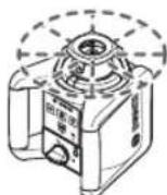
Potaunohen pekHM
Potaunohnopekm e oco6eHO npenopaunb npn yontpe6aHa nacepcknotnpneMnK. Moke da 6napate Mey pa3nnuHb 6p3HHn Ha potaunja.
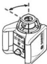
ПИИСКР exKIM
Bo oboj pexkIm ha pa6ota, Bapna6bnHnOt nacepckn 3paK ce DnKn BO orpaHnueh aorJHa OTbopaHe.
PnToa, BUNHBOCTa Ha IacepckHot 3paek e3rolemeha Bo cnope6ba co potauonHOHT pekm. Moke da 6npate Mery pa3nnu arnHa OTBopahe.
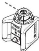
Toekact pexnM
Bo OBOj pexHm Ha paBota ce noctnHyBa Hajno6pa BnInNBOcT Ha BapnJaBnHnOtnacepckn 3pak. ToJ ha np. cnJyKn 3a eHNOCTABHO npeHecyBaBe Ha BNCHH NIN 3a KOHTpOHa nPabNTe IHHN.
JIHHHCKNHTOuKAcTpeKHM He ce HameHeTH 3a yNoTppe6a coIacepckNOt npHemNHK (36).

PotaunohenpeKHM
No cekoe BknyuBaHe, MepHNO tyepe Ce Haofo Bo potaunoHep pexm co ctaHapHa 6p3nHa Ha poTaunja. (300 min-1).
3a MeHyBaBe OJ INHnCKn BO potaNoHOe peXHM, nPHTNCHeTe ro KOnyTo 3a potaNoHOe peXHM (5) nN KOnyTo 3a potaNoHOe peXHM (26) Ha daJeHHcknOT ynpabyBa.
3a npomeHa ha 6p3nHaTa ha potaunja, npntnckajte ro konyeto 3a potaunohen pexm (5) nHn KOnyeto 3a potaunohen pekm (26) Ha daJeuHcKnOT ynpabyBaU, doKeHa He ja NoCTnHrTe caKaHaTa 6p3nHa.
Ppna pabota co nacepcn npneMHNK, Tpe6a da ja na h36pepe HajronemaTb 6p3nHa ha potaunja. Ppna pa6oTa 6e3ncepcn npneMHNK, HamaIe Ta 6p3nHaTa Ha potaunJa 3a noo6pa BnIMBOCT Ha nacepcKnOT 3pak N KopncTe neacepckn OuHa (46).

JIHHNCKPepKHM/TOOKaCtpeKHM
3a npomeHa BO NHHCKn peKHM Ond. TOUkAcT peKHM, npHTCHHeTo KOJyTeTo 3a NHHCKn peKHM (11) nn KONyTeTo 3a NHHCKn peKHM (27) Ha daJeuHckNtO ynpabyBa.
MepHnOT anapat Ce MeHyBa BO HnHnCKn peKm CO HajMaHnOT aRan Ha OTBopAhe.
3a npomeHa ha aroIOT Ha OTBopaHe npHTNCKajTe ro NOctoJaHO KOUeTO 3a IHHNCn peKIM (11) INI KOnTcTo 3a IHHNCKn peKIM (27) Ha daJIeHnHCKnOt ynpaByBa,doEka He ce noJABn cakAHOT peKIM Ha pa6Ota. ArONOT Ha OTBopaHe ce 3rOEnMyBa NocTeNo npi CeKeoe npHTNCKaHe, nCTOBpeMeHo ce 3rOEnMyBa n 6p3Hata Ha potauiJa co CeKOj CTenEH.
MepHnOtypeCe MeHyBa NO kpaTko OcunInnpaBe BO TOUkAcT peKHM CO HajMaJIHOT aRan Ha OTBopaHe. Co OJHOBO npTHCKaBe HA KONHTe 3a JINHnCKn peKn (11) BOn HaaD KOH INHHCKNt peKHM CO HajMaJIHOT aRan Ha OTBopaHe.
Hanomeha: Iopadn Hnepujna, Iacepot Ocunnpajk moke da n3ne3e MaNKy Hnd KpaJHte ToKHa Naacepckata nnHja.
Функци
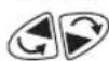
BpTeJe jaHHnjaT/Toqkata BO XOpH3OHTaHaBO potaunHOto HNO (BnH cnka A)
Pa6oTeHe co MepHa IeTBA (onpeMa) (BnH cInKa E)
3a KOHTPOna Ha pAMHHN HIN 3a HAHeCyBaHBe Ha KocHN Ce npenopayBa KopncTeHb Ha MePhaJeTBA (37) 3aeHNO Co IacepCKnOT npHemHKn.
Ha Mephata letBa (37) rope hma haHeceHO peaTHBHa
Mepha cKaAna. Hej3nHata hynta BncnHa moKe da ja n36peTe
dony Ha n3ne3OT. Ha Toj hauHH dIpeKTHo ce OTHTyBaat
OTCTanyBaHaTa oD 3aadHeHATA BcNHa.
Iacepcn 3aunTHH ouHa (onpema)
Nacepckte 3aunTHnOuHa ja qHHTnpaaT OKoHata CBETnHa. Ha ToJ HauHH CBeTnOTo Ha Nacepot n3rIeJa NOCBETNo 3a OKOTO.
He rKnopctete nacepcknte 3aunTHn Ounna (dononHHTenHa onpeMa) kako 3aunTHn Ounna.
Iacepcknte 3aunTHn Ounna cnuykat 3a noOpbo paCno3HaBaHbe Ha Iacepcknot 3paK; cenak, Tne He IHTAT od Iacepckto3pauehe.
He rKopnCTeIacepcknte3aHTTHOcHna (DononHnTeHa onpeMa) kako ouHna 3a coHue Hn naK Bo coo6paKaJot. Iacepcknte ouHna He DaBaat cenocha UV-3aHTTa nTo HaMaanyBaat npen03HaBaHbeto Ha 60n.
Ppimepn 3a pa60Ta
PpehcyBahe/koHTpOHa BnCHnH (BnH CnHKaF)
IocTaBeTe ro MEPHnOT ypeD BO XOpH3OHTaHa nOIOX6a Ha CBpCTa NODIora Hm MOHTnpajTe ro Ha cTaTHB (38) (onpema).
Pa6oTeHe co CTAHb: H3paMHeTe ro IacepckHot 3paK Ha cakaHaTa BnCnHa. IpeneCeTe ja OIN. npOBepeJa BnCnHaTa HA CEHNHO MECTo.
Pa6oTeHe 6e3 cTaTnB: odpeTe ja BmCnHckata pa3nHa nOmeIy nacepCKNt 3paK I BmCnHata Ha pepepeHTnA ToUka Co NOMOu HA ueHATA TaBna Ha nacepot (47).
PpeHecete ja OJN. npOBepete ja H3MepeHata BnCHcKa pa3Nka Ha ueHHTO MecTo.
H3pAMHeTe ja npaJIeHNo TocKaHa BePHTKanata Harope/HaHecete npab aorn (Bnuu cnka G)
Iokony Tpe6a da ce HaHece npab aron nn da ce n3paMHaT MeysIOBNTe, Mopa da ja n3pAMHnTe TOkata Ha BeptHKanata Harope (9) napaneHIO, T. e. Ha NcTo pactoJAHne co pepepeHTnA tnnHna (ha np. sD).
3a Oba, noCTaBeTe ro MEPHnOT ypeB Bo BEPTKanHa nOIO6bA H No3NIOHnpajTe Ro Ha ToJ haunuToToukata Ha
BepTKanata Harope Ke OIN CKOPo npaJIeHnHa pepepeHThata nnHJa.
3a TOHNO3HIOHOHHaBe H3Mepete ro pactoJAHHeTo MeIy TOKATA HA BepTKAaTA Harope n pepepeHTHa TINHJa DNPEKTHO HA MEPHnOT ypeD CO NOMOu HA CEJIHATA Tabla 3a Nacepot (47).N3Mepete ro OndHOBO pactoJAHHeTO NOMEy TOKATA HA BepTKAanTA Harope n pepepeHTa TINHJa BO ITO E MOXHO NoroJeMo pactoJAHne OD MEPHnOT ypeD. HacoueTe ja ToKATA HA BepTKAanTA Harope, Taka wTo Ke IMA hCTo pactoJAHne DO pepepeHTHa TINHJa, KAKO INpHi MEpeheTo DnEeKTHO HA MEPHnOT ypeD.
Ke ce npnkae npaBnot aorO ToKkata Ha BepTKkanaT Harope (9) co BapnjaBnHNoT nacepckn 3paK (6).
PnKakyBaBe Ha BepTHKaHa/BepTKaHNO HNBO (Bnu n cHka H)
3a npkaKyaBaHe Ha BepTknA oHn. BepTknA HnBO, noCTaBeTe ro MEPnHOT ypeD BO BepTknA HnNoX6a. DOKONy BepTknA HnO Tope6a da 6ne NoI npab aroJ do pepepeHTHa TnHJa (Ha np. Snd), toraun n3pamHete ja ToKata Ha BepTknA tHa Horpe (9) Ha OBaa pepeeHTHa nnHja.
BepnkaIata ce npkaKyBa npeky BapnaHnHnot nacepckn 3paK (6).
H3paMHyBaBe Ha BepTHKana/BepTHKaIHO HNBO (BnDcnKaiI)
3a da ja n3pamnhte Iacepckata nnHnja nnpoTaoHONO HNBO Ha eHa pepeepentHa ToKa Ha SNI, NoCTaBeTe ro MepHNOt ypeD Bo BepTNkAHa NIOX6b nnPamHeJa nacepckata nnHnja OIN. POtauHOTo HNBO rpybo Ha pepepeENThata ToKa. 3a TOHNo n3pamHyBahe co pepepeENThata ToKa, BPTeTe r POtauHOTo HNBO OKOly
BepTNKaJIHaTAtOcKa(BHn,BteHeHa potaUNHOTo HNBO Bo BepTNKaJIHaNoJX6a (BNHcnkaB),CTpaHua251).
Pa6oTeHe 6e3 nacepckn nphemHK (BmH cInka J)
Pn noBONH CBETNOCHY yCNOB (TeMHa OKOINHa) Ha KaTKn paTOjaHHa MoKe da paBOHTe 6e3 NacepCKn npHemHK. 3a nOobpa BnINBOCT Ha nacepCKNOT 3pak H3bepete Nn NnNcKn peKHM, Nn ToKAcT peKHM n BpTeTo NacepCKNOT 3pAK KOH cENHOTo MECTO.
Pa6oTebe co Iacepckn npHmHK (BnD nCnka K)
Pn HENOBONH CBETIOCHY YCNOB (OCBETNEHa OKOINHa, DnpeKTTH COHcEBN 3paun) Ha rolemn pactoJAHJa 3a noD6po Haorabe Ha nacepcknot 3pak Kopnctete ro nacepcknot npemHHK (36). Pn pa60a co nacepckn npemHHK, h6epete ro potaOHnptexm Co haJBNCOK 6p3nHa ha potauna.
Mephe ha ronem npctojaHHja (Bn nnka L)
PnMpeHbHa rolempaCtojaHjna,napccknot
PnEMHK (36) Mopa Da CE KOPNCTa HaafoaHe Ha
Nacepcknot 3pak.3a Da CE HAManat Pneuknte,MEPHNO
yepTpe6aDa rnoocTaByaTe cekoraB Wo CpeDnHaTa Ha
paBoTHa NOBpuHHa N da rnoocTabte HA CTATNB.
PaboTebe BO hAdBopeweH npocTOp (BnDn CnNka E)
Bo naBbpeHn npocTOp, cekorau Tpe6a da ce KopncTn Iacepckn npemHHK (36).
Pnpa6oTeHeHaHecnpyeHIOI,MOHTnpajTe Ro MepHnoT ypeHa cTaTnBOT (38).Pa6oTe cMoCo aKTHBnpaHa 0yHKuJa 3a PpeDyPpeDyBaHe 3a yDap,3a Da N36eHete nOrpeShn MepeHa npi DnHexeHe Ha NoDTo HnNtpeCn Ha MePHNoType.
IperneHa npka3nte 3a potaunohen Iacep
Ten./paKc:02/2467610
Mo6.:070595888
Д.П.T.Y "POJKA"
JAnI NykpOBcKn 66; T.IA ABTOKOMaHda loKaI 69
1000 Ckonje
E-nouta: servisrojka@yahoo.com
Ten: +389 2 3174-303
Mo6: +389 70 388-520, -530
IOnonHnTeHH aDpeCN Ha cepBnCn MoKe da HajdeTe noi:
www.bosch-pt.com/serviceaddresses
OtctpaHyBaIbe

EneKtpnHHTe ypei,akymynatopcknte 6aTeepn/6aTepnIte,onPemata n am6aJaxnTe Tpe6a da ce oTcpaHaT Ha ekonoWKn npnphiTINB HauHH.

He n pfpnajte enektpnHnTe ypeu n 6aTeepnTe BO domaunHa KaHTa 3a OTnadoon!
Cama 3a 3emjnte oEY:
CnopeE EBponckata perynatna 2012/19/EU eNEKTPnHHTe ypeDN WTO CE BOYnoTpe6a NdeFeKTHNTE nIN HCKOPNCTeHNTE 6aTePN CNopeD perynatNBATA
2006/66/EC mopa oDJIeIHO da ce co6epa n da cepeuKIIpaat 3a NOBtropHa yNtpe6a.
Srpski
Sigurnosne napomene za rotacioni laser i daljinski upravljac

Morate da procitate i uvaizite sva uputstva kako biste radili bez opasnosti i bezbedno. Ukoliko ne postujete postojeca uputstva, moze doci do ugrozavanja funkcije
mehanizama za zastitu. Ploce sa upozorenjem ne smeju da budu neprepoznatljive. DOBRO SACUVAJTE OVA UPUTSTVA I PREDAJTE IH ZAJEDNO SA PROIZVODIMA, AKO IH PROSLEDUJETE DALJE.
Paznja -ukoliko primenite drugacije uredaje za rad ili podesavanje, osim ovde navenenih ili sprovodite druge vrste postupaka, to moze dovesti do opasnog izlaganja zračenju.
Merni alat se isporučuje sa pločicom uz upozorenje za laser (označeno u prikazu mernog alata na grafickoj stranici).
Ukoliko tekst na pločici sa upozorenjem za laser{nijena vašem jeziku, prelepite je sa isporučenomnalepnicom na vašem jeziku, pre prvog pušanja u rad.
Nemojte da vrsite promene na laserskoj opremi.
Nemoje koristiti laserske naocare (pribor) kao zastitne naocare. Laserske naocare sluze za bolje prepoznavanje laserskog zraka. Medutim, one ne stite od laserskog zracenja.
Nemojte koristiti laserske naocare (pribor) kao naocare za suntce ilu saobracaju. Laserske naocare ne pruzaju potpunu UV zastitu i smanjuju percepcjju boja.
Proizvode sme da popravlja samo kvalifikovano osoblje i samo sa originalnim rezervnim delovima. Time se obezbeduje, da sigurnost ostane sačuvana.
www.bosch-pt.com/serviceaddresses
Uklanjanje dubreta

Elektricne uredaje, akumulatore/baterije, pribori pakovanja treba predat na reciklaukoja je u skladu sa zašitomživotne sredine.
Elektricne uredaje i akumulatore/baterij nemojte da bacate u kucho smece!

Samo za EU-zemlje:
Prema evropskoj smernici 2012/19/EU više neupotrebljivi elektrčni uredaji ne moraju, a prema evropskoj smernici 2006/66/EC ne moraju ni akumulatorske baterije/baterije koje su u kvaru ili astrosene da se odvojeno sakupljaju i odvoze na reciklažu koja odgovara zaštiti Čovekove sredine.
Slovenscina
Varnostna opozorila za rotacijski laser in daljinski upravljalnik

www.bosch-pt.com/serviceaddresses
Odlaganje

Elektricne naprave, akumulatorske baterije/ baterije, pribor in embalazo morate recikirati na okolju prijazen nacin.

Elektrichnih naprav in akumulatorskih/obicajnih baterij ne smete odvreci med gospodinjske opadke!
www.bosch-pt.com/serviceaddresses
Zbrinjavanje

Elektricne alate, aku-baterije/baterije, pribor i ambalazu treba dovesti na ekološki prihvatljivo reciklaranje.

Elektricne alate i aku-baterije/baterije ne bacajte u kuci opdat!
Samo za zemlje EU:
Sukladno europskoj Direktivi 2012/19/EU elektrichi uredaji koji vishe nisu uporabivi i sukladno europskoj Direktivi 2006/66/EZ neispravne ili astrosene aktu-baterije/baterije moraju se odvojeno sakupljati i davesti na ekoloski prihvatljivo recikliranje.
Eesti
www.bosch-pt.com/serviceaddresses
Jätmekäitlus

Lazera skatbrilles (papildiederums)
www.bosch-pt.com/serviceaddresses
www.bosch-pt.com/serviceaddresses
糜粟

www.bosch-pt.com/serviceaddresses
废弃处理
www.bosch-pt.com/serviceaddresses
廢棄物處理

www.bosch-pt.com/serviceaddresses
司

前通同公,委正用包T/贝T,,
前通同公及中首正用包托力/包托力将告定
欧习EU国台安
迪启昌,人 2012/19/EU及用法gaii3Rin2006/66/EC
In
Tuuu uWnuaaunnuu Iauanrnnvnuu

nnaaunnnnnaanennnnn nannnnn nnannnnnnnnnnnnnnnnnnnnnnnnnnnnnnnnnnnnnnnnnnnnnnnnnnnnnnnnnnnnnnnnnnnnnnnnnnnnnnnnnnnnnnnnnnnnnnnnnnnnnnnnnnnnnnnnnnnnnnnnnnnnnnnnnnnnnnnnn
nannnnnnaaennnnnnaanennn nnnnnn nn nnnnnnnnnnnnnnnnnnnnnnnnnnnnnnnnnnnnnnnnnnnnnnnnnnnnnnnnnnnnnnnnnnnnnnnnnnnnnnnnnnnnnnnnnnnnnnnnnnnnnnnnnnnnnnnnnnnnnnnnnn
- 1
(
nwnnnnnaaannnnnnaanennnnnnae nnnnnnnae
aannnnnnaaennnnnnae
aunnnnnaannnnnnaanennnnae (aunnnnna) uuuuunnnnnnnnnnnnnnnnnnnnnnnnnnnnnnnnnnnnnnnnnnnnnnnnnnnnnnnnnnnnnnnnnnnnnnnnnnnnnnnnnnnnnnnnnnnnnnnnnnnnnnnnnnnnnnnnnnnnnnnnnnnnnnnnnnnnnnnnn
1 1
nannnnnnnnnnnnnnnnnnnnnnnnnnnnnnnnnnnnnnnnnnnnnnnnnnnnnnnnnnnnnnnnnnnnnnnnnnnnnnnnnnnnnnnnnnnnnnnnnnnnnnnnnnnnnnnnnnnnnnnnnnnnnnnnnnnnnnnn
aunnnnnaeannnnnnae annnnnne aen nnnnnae
yuvuunnuunnuunnuunnuunnuunnuunnuunnuunnuunnuunnuunnuunnuunnuunnuunnuunnuunnuunnuunnuunnuunnuunnuunnuunnuunnuunnuunnuunnuunnuunnuunnuunnuunnuunnuunnuunnuunnuunnuunnu
GRL 250 HV:
aannnnnnaananaananaananaananaananaananaananaananaananaananaananaananaananaananaananaananaananaananaananaananaananaananaananaananaananaananaananaananaananaananaananaananaananaananaananaananaananaananaananaananaananaananaananaananaananaananaananaananaananaananaanaraannnnaannnnaannnnaannnnaannnnaannnnaannnnaannnnaannnnaannnnaannnnaannnnaannnnaannnnaannnnaannnnaannnnaannnnaannnnaannnnaannnnaannnnaannnnaannnnaannnnaannnnaannnnaannnnaannnnaannnnaannnnaannnnaannnnaannnna
aannnnnnaananaananaananaananaananaananaananaananaananaananaananaananaananaananaananaananaananaananaananaananaananaananaananaananaananaananaananaananaananaananaananaananaananaananaananaananaananaananaananaananaananaananaananaananaananaananaananaananaananaananaanaraannnnaaa
nnnnnnnnnnnnnnnnnnnnnnnnnnnnnnnnnnnnnnnnnnnnnnnnnnnnnnnnnnnnnnnnnnnnnnnnnnnnnnnnnnnnnnnnnnnnnnnnnnnnnnnnnnnnnnnnnnnnnnnnnnn
nauanuunnuuaunnnn nannnnnaaennnnnnaa aannnnnnnnnnnnn
354
nnaananaananaananaananaananaananaananaananaananaananaananaananaananaananaananaananaananaananaananaananaananaananaananaananaananaananaananaananaananaananaananaananaananaananaananaananaananaananaananaananaananaananaananaananaananaananaananaananaananaananaanaraannnnnnnnnnnnnnnnnnnnnnnnnnnnnnnnnnnnnnnnnnnnnnnnnnnnnnnnnnnnnnnnnnnnnnnnnnnnnnnnnnnnnnnnnnnnnnnnnnnnnnnnnnnn
aannnnaaannnnn
nnaaannnnnnaananaananaananaananaananaananaananaananaananaananaananaananaananaananaananaananaananaananaananaananaananaananaananaananaananaananaananaananaananaananaananaananaananaananaananaananaananaananaananaananaananaananaananaananaananaananaananaananaananaananaanara
nnaaannnnnnaanennnnnnaanennnnnnaanennnnnnaanennnnnnaanennnnnnaanennnnnnaanennnnnnaanennnnnnaanennnnnnaanennnnnnaanennnnnnaanennnnnnaanennnnnnaanennnnnnaanennnnnnaanennnnnnaanennnnnnaanennnnnnaanennnnnnaanennnnnnaanannnnnnaanennnnnnaanennnnnnaanennnnnnaanennnnnnaanennnnnnaanennnnnnaanennnnnnaanennnnnnaanennnnnnaanennnnnnaanennnnnnaanennnnnnaanennnnnnaanennnnnnaanennnnnnaanennnnnnaanennnnnnaanennnnnnaanennnnnna anannannannannannannannannannannannannannannannannannannannannannannannannannannannannannannannannannannannannannannannannannannannannannannannannannannannannannannannannannannannannannannannannannannannannannannannannann ann ann ann ann ann ann ann ann ann ann ann ann ann ann ann ann ann ann ann ann ann ann ann ann ann ann ann ann ann ann ann ann ann ann ann ann ann ann ann ann ann ann ann ann ann ann ann ann ann ann ann ann ann ann ann ann ann ann ann ann ann ann ann ann ann ann ann ann ann ann ann
nnaaannnnn
aunnnnnaeannnnne aen nnnnne anennnne
nivvov
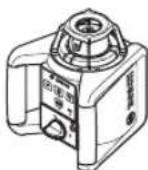
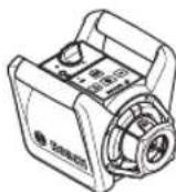
nunnuuunnuu 7nuuunnuuunnuu 7nuuunnuuunnuu uuuuuuuuuuuuuuuuuuuuuuuuuuuuuuuuuuuuuuuuuuuuuuuuuuuuuuuuuuuuuuuuuuuuuuuuuuuuuuuuuuuuuuuuuuuuuuuuuuuuuuuuuuuuuuuuuuuuuuuuuuuuuuuuuuuuuuuuuuuuuuuuuuuuuuuuuuuuuuuuuuuuuuuuuuuuuuuuuuuuuuuuuuuuuuuuuuuuuuuuuUU
nnaa-nnnn
aovvuaiauauauauauauauauauauauauauauauauauauauauauauauauauauauauauauauauauau
1 1 1 1 1 1 1 1 1 1 1 1 1 1 1 1 1 1 1 1 1 1 1 1 1 1 1 1 1 1 1 1 1 1 1 1 1 1 1 1 1 1 1
360
yuaanannnnnnaa aenanae ananennnnae
aannnnnnaanennnnnnnnnnnnnnnnnnnnnnnnnnnnnnnnnnnnnnnnnnnnnnnnnnnnnnnnnnnnnnnnnnnnnnnnnnnnnnnnnnnnnnnnnnnnnnnnnnnnnnnnnnnnnnnnnnnnnnnnnnnnnnnnnnnnnnnnnn
nunnuuunnuuunnuuuuuuuuuuuuuuuuuuuuuuuuuuuuuuuuuuuuuuuuuuuuuuuuuuuuuuuuuuuuuuuuuuuuuuuuuuuuuuuuuuuuuuuuuuuuuuuuuuuuuuuuuuuuuuuuuuuuuuuuuuuuuuuuuuuuuuuuuuuuuuuuuuuuuuuuuuuuuuuuuuuuuuuuuuuuuuuuuuuuuuuuuuuuuuuuuuuuuuuuuUU
nannnnnnuu:uu=unnnnnnnnnnuu uuuu
(42)(40)(39)
nnuu: nnuuunnuu (42) unuu (41) lnuuunnuuuuuuuuuuuuuuuuuuuuuuuuuuuuuuuuuuuuuuuuuuuuuuuuuuuuuuuuuuuuuuuuuuuuuuuuuuuuuuuuuuuuuuuuuuuuuuuuuuuuuuuuuuuuuuuuuuuuuuuuuuuuuuuuuuuuuuuuuuuuuuuuuuuuuuuuuuuuuuuuuuuuuuuuuuuuuuuuuuuuuuuuuuuuuuuuuuuuuuuuuuUU
()
muaaun 16 m. nannn (43) naunu uauu uauu uauu uauu uauu uauu uauu uauu uauu uauu uauu uauu uauu uauu uauu uauu uauu uauu uauu uauu uauu uauu uauu uauu uauu uauu uauu uauu uauu uauu uauu uauu uauu uauuu
nunnuuunnuuuuuuuuuuuuuuuuuuuuuuuuuuuuuuuuuuuuuuuuuuuuuuuuuuuuuuuuuuuuuuuuuuuuuuuuuuuuuuuuuuuuuuuuuuuuuuuuuuuuuuuuuuuuuuuuuuuuuuuuuuuuuuuuuuuuuuuuuuuuuuuuuuuuuuuuuuuuuuuuuuuuuuuuuuuuuuuuuUU
nunnnnnnnnnnnnnnnnnnnnnnnnnnnnnnnnnnnnnnnnnnnnnnnnnnnnnnnnnnnnnnnnnnnnnnnnnnnnnnnnnnnnnnnnnnnnnnnnnnnnnnnnnnnnnnnnnnnnnnnnnnnnnnnnnnnnnnnnnnnnnnnnnnnnnnnnnnnnnnnnnnnnnnnnnnnnnnnnnn nn nannn nn nannn nn nannn nn nannn nn nannn nn nannn nn nannn nn nannn nn nannn nn nannn nn nannn nn nannn nn nannn nn nannn nn nannn nn nannn nn nannn nn nannn nn nannn nn nannn nn nannn nn nannn nn nannn nn nannn nn nannn nn nennn nn nannn nn nannn nn nannn nn nannn nn nannn nn nannn nn nannn nn nannn nn nannn nn nannn nn nannn nn nannn nn nannn nn nannn nn nannn nn nannn nn nannn nn nannn nn nannn nn nannn nn nannn nn nannn nn nannn nn nannn nn n ann
aunnnn/wnn (anwnnnn 1)
nunnnnnnnnnnnnnnnnnnnnnnnnnnnnnnnnnnnnnnnnnnnnnnnnnnnnnnnnnnnnnnnnnnnnnnnnnnnnnnnnnnnnnnnnnnnnnnnnnnnnnnnnnnnnnnnnnnnnnnnnnnnnnnnnnnnnnnnnn
yunanyuunnnn (g"ynnuu yuyu u chunuuluuu (gnwnuB), nu 360)
nannnnnnaaennnnnnae (nannnnnnae K)
nuananaananaananaananaananaananaananaananaananaananaananaananaananaananaananaananaananaananaananaananaananaananaananaananaananaananaananaananaananaananaananaananaananaananaananaananaananaananaananaananaananaananaananaananaananaananaananaananaananaananaan ana an
nna (nwnuun L)
wannnnn nn nnnnnnnnnnnnnnnnnnnnnnnnnnnnnnnnnnnnnnnnnnnnnnnnnnnnnnnnnnnnnnnnnnnnnnnnnnnnnnnnnnnnnnnnnnnnnnnnnnnnnnnnnnnnnnnnnnnnnnnnnnnnnnnnnnnnnnnnnnnnnnnnnnnnnnnn nn
nannanun (nnnnnae E)
nanae nnnaaee (36) nannnnnnae
nae
nnuuwwwnuwaanrnnnne 7
(38) aunnuwauwunnuwunnuwunnu w
nuuunnu wunnuwunnuwunnu w
y
| ### | ### | ### | ### | ### |
| ### | ### | ### | ### | ### |
| ### | ### | ### | ### | ### |
| ### | ### | ### | ### | ### |
| ### | ### | ### | ### | ### |
| ### | ### | ### | ### | ### |
| ### | ### | ### | ### | ### |
| ### | ### | ### | ### | ### |
| ### | ### | ### | ### | ### |
| ### | ###
### | ### | ### | ### |
| ### | ### | ### | ### | ### |
| ### | ### | ### | ### | ### |
| ### | ### | ### | ### | ### |
| ### | ### | ### | ### | ### |
| ### | ### | ### | ### | ### |
| ### | ### | ### | ### | ### |
| ### | ### | ### | ### | ### |
| ### | ### | ### | | |
: Tnnnnsnnnaaiaea 2x/s: nunnuu (nu uauuunuun) o:
nVvNnaa
nnae nnnnnae nnnnne nnnnne nnnnne nnnnne nnnnne nnnnne nnnnne nnnnne nnnnne nnnnne nnnnne nnnnne nnnnne nnnnne nnnnne nnnnne nnnnne nnnnne nnnnne nnnnne nnnnne nnnnne nnnnne nnnnne nnnnne nnnnnee nnnnne nnnnne nnnnne nnnnne nnnnne nnnnne nnnnne nnnnne nnnnne nnnnne nnnnne nnnnne nnnnne nnnnne nnnnne nnnnne nnnnne nnnnne nnnnne nnnnne nnnnne nnnnne nnnnne nnnnne nnnnae
nwnnnnnnnnnnnnnnnnnnnnnnnnnnnnnnnnnnnnnnnnnnnnnnnnnnnnnnnnnnnnnnnnnnnnnnnnnnnnnnnnnnnnnnnnnnnnnnnnnnnnnnnnnnnnn
nannnnnnaanennnnnnnnnnnnnnnnnnnnnnnnnnnnnnnnnnnnnnnnnnnnnnnnnnnnnnnnnnnnnnnnnnnnnnnnnnnnnnnnnnnnnnnnnnnnnnnnnnnnnnnnnnnnnnnnnnnnnnnnnnnnnnnnnnnnnnnnnnnnnnnnn nn nannnnaaannnannnannnannnannnannnannnannnannnannnannnannnannnannnannnannnannnannnannnannnannnannnannnannnannnannnannnannnannnannnannnannnannnannnannnannnannnannnannnannnannnannnannnannnannnannnannnannnannnannnann
lnn ln nnnn nn nnnn
2525 4
10110
In: +66 2012 8888
wn: +66 2064 5800
www.bosch.co.th
ywnnnnnaaannnnnnnn
Gn2
10/11 m 16
www.bosch-pt.com/serviceaddresses
#

Suplai daya remote control
Palma Tower 10th Floor
Jalan RA Kartini II-S Kaveling 6
Pondok Pinang, Kebayoran Lama
www.bosch-pt.com/serviceaddresses
Cara membruang

May Do Cao Trinh Laze Xoay
Dung cu do duoc thiét ké dé xác dinh vα kiem tra do chinh xac cua cac vach ngan nam ngang, cac duong thang dung, vach duong chi dinh thi cóng xay dung va cac diem ung day doi.
Dung cu do phu hop de su dung trong vung ben ngoai va ben trong.
Thiet bi dieu khién tu xa
Dieu khien tu xa duoc thiet ke de dieu khien laser Bosch xoay bang tia hong ngoai.
Thiet bi dieu khien tu xa phu hop de su dung trong vung ben ngoai va ben trong.
Cac bo phan duoc minh hao
Su dān só cac bó phan duoc minh hoa lá de tham kháo hinh minh hoa cuà dung cu do va dieu khién tu xa tren trang hinh anh.
Laser xoay/thiet bi sac
(1) Hien thi chuc nang canh bao va cham
(2) Nút canh bóva cham
(3) Hien thi trang thai
(4) Phim Bāt/tāt
(5) Nút ché do vān hàn xoay
(6)Luong lae bian dai
(7) Cam bién cho dieu khién tu xa
(8) Cua chieu luong laze
(9) Diem chuan len tren
(10) Núm xoay
(11) Nút Ché do vān hàn thàng
(12) Den bao dung luqng pin thap
(13) Bô pin
(14) Khoang lap pin
(15) Khoa ngan chu'pa pin
(16) Khóa giu bô pin
(17) cam sac
(18) Thié t bi sac
(19) Phich cām cuà thiet bi sac
(20) Phich cam sac
(21) Diem nhanh giadobacha n5/8"
(22) Ma seri san xuat
(23)Nhan canh bao laser
(24) Bién canh bao cua chieu Laser (GRL 300 HV/GRL 300 HVG)
A) Phu tung duoc trinh bay hay mo ta khong thai la mot phan cua tieu chuan hang hoa duoc giao kem theo san pham. Ban co the tham khao tong the cac loai phi tung, phi kien trong chuong trinh phi tung cua chung toi.
Thiet bi dieu khien tu xa
(25) Thiêt bi dieu khién tu xa
(26) Nút ché do vanh hàn xoay
(27) Nút Ché do vān hànghang
(28) Nút thiet lap lái canh bóva cham
(29) Vǎn nút theo chieu kim dong hô
(30) Vǎn núnt nguòc chieùkim dong hó
(31) Hien thephat tin hieu
(32) Cua chieu tia hong ngoai
(33) Ma seri san xuat
(34)Laycainapdaypin
(35) Nap day pin
Phu kien/Phu tung thay the
(36) Bô thu laser
(37) Thanh do
(38) Giá do ba chan
(39) Vít có dinh cuá gía gán tuong
(40) Cac Igán cua giagan tuong
(41) Khung lapgia ba chan 5/8" cua gia gan tuong
(42) Giá gán tuǒng/dōn vì can chīnh①
(43)Vitodonvi can chinhA
(44) Vít 5/8" cúa gía gán tuong
(45) Nam cham
(46) Kinh nhin tia laser
(47) Bäng dfch tia laser
(48) Cop xeA
A) Phu tung duoc trinh bay hay mo ta khong thai la mot phan cua tieu chuuan hang hoa duoc giao kem theo san pham. Ban co the tham khao tong the cac loai phi tung, phi kien trong chuong trinh phi tung cua chung toi.
Thong so ky thuat
| Mệnh Do Cao Trinh Laze Xoay | GRL 250 HV GRL 300 HV GRL 300 HVG |
| Mã sõ may | 3 601 K61 6.. 3 601 K61 5.. 3 601 K61 7.. |
| Pham vi lam viếc (Bân kinh)A(B) | |
Teng Viet 379
| Mệnh Do Cao Trinh Laze Xoay | GRL 250 HV GRL 300 HV GRL 300 HVG |
| - khùng có thiet bi thu laze, khoáng. | 30 m 30 m 50 m | | |
| - có thiet bi thu laze, khoáng. | 0,5-125 m 0,5-150 m 0,5-150 m | | |
| Cộng chuan chinh xac(A)C) | ±3 mm (δ 30 m) ±3 mm (δ 30 m) ±3 mm (δ 30 m) | | |
| Pham vu can bang | ±8% (±4,6°) ±8% (±4,6°) ±8% (±4,6°) | | |
| Thói gian lay ctot chuy chuán tièu bieu | 15 s 15 s 15 s | | |
| Tóc do xoay | 150/300/600 min1 | 150/300/600 min1 | 150/300/600 min1 |
| Góc mõ ché do vân khác tháp | 10/25/50° | 10/25/50° | 10/25/50° |
| Nhiét do hoat dōng | -10°C ... +50°C | -10°C ... +50°C | +40°C |
| Nhiét do luu kho | -20°C ... +70°C | -20°C ... +70°C | -20°C ... +70°C |
| Chiéu cao的能量 tõi da qua chiei cuo tham chiei | 2000 m | 2000 m | 2000 m |
| Dó am khòng khác tuong dõi tõi da. | 90 % | 90 % | 90 % |
| Múc do bān theo IEC 61010-1 | 2D) | 2D) | 2D) |
| Cáp do Laser | 23R 3R | | |
| Loqi Laser | 635 nm, < 1 mW | 635 nm, < 5 mW | 532 nm, < 5 mW |
| Phân ký | 0,4 mrad (góc dãy) | 0,4 mrad (góc dãy) | 0,4 mrad (góc dãy) |
| Diém khác gaia dō ba chan theo chiei ngang | 5/8" -11 | 5/8" -11 | 5/8" -11 |
| Pin (NiMH) | 2 × 1,2 V HR20 (D)
(9 Ah) | 2 × 1,2 V HR20 (D)
(9 Ah) | 2 × 1,2 V HR20 (D)
(9 Ah) |
| Pin (kiém-mangan) | 2 × 1,5 V LR20 (D) | 2 × 1,5 V LR20 (D) | 2 × 1,5 V LR20 (D) |
| Trong l权重 theo Qui trinh EPTA-Procedure 01:2014 | 1,8 kg | 1,8 kg | 1,8 kg |
| Kích huếc (chieu dai × róng × cao) | 190 × 180 × 170 mm | 190 × 180 × 170 mm | 190 × 180 × 170 mm |
| Múc do bao vê | IP 54 (duoc bó vê
chóng bui và tia nuóc) | IP 54 (duoc bó vê
chóng bui và tia nuóc) | IP 54 (duoc bó vê
chóng bui và tia nuóc) |
A) 25^
B) Pham vi lam Vietc co the duoc giam thong qua cac dieu kien moi truong khong thuan lgi (vi du nu tia ma t tri chieu truc tiep).
C) doc theo cac truc
D) Chi có chat bān khong dan xuàt hien, nhung doi khi do dan dien tam thoi gay ra do ngung tu. So xeri (22) deu duc ghi trén nhān mac, de de dang nhān dang loai may do.
www.bosch-pt.com/serviceaddresses
Su'thai bo
Cac thiet bi dien, acqui/pin, phu kien va bao bi can duoc tai su dung theo quy dinh ve moi truong.
Khong vut thiét bi dien va pin/ac quy cung trong rac thai cua gia dinh!
Chi dānh chocac quocgia thuoc khoi Lien minh Chau Au (EU):
Cac dung cu dien cam tay khong cng già tri su dung theo chi thi chau Au 2012/19/EU va ac quy/ pin bi hong hoac da qua su dung theo chi thi so 2006/66/EC phai duoc thu gom rieng va co the tai su dung theo luat moi truong.
JgAaGRL300HV, GRL300HVG
jullgaiolai juiy wulll ose gplsswlsic lqao go ccl.aydagly .wulall
aalp 1ybl a bly aiee aee
3R juU i jj jq pSsi Sic gJy
p 50 y .aiSauI auau I ouau
. uI U pKu
jlll jlgJdoJUJU JI JI JI JI JI JI
LgcljogUdawJg 1 g jy Jg UJg Jg Jg Jg Jg Jg Jg Jg Jg Jg Jg Jg Jg Jg Jg Jg Jg Jg Jg Jg Jg Jg Jg Jg Jg Jg Jg Jg Jg Jg Jg Jg Jg Jg Jg Jg Jg Jg Jg Jg Jg Jg Jg Jg Jg Jg Jg Jg Jg Jg Jg

oaiy laolil ojiaial. jaiill 1o huiuiehutge jieinluptejshulc yolg jai yasw
jaoa aasaaa aagaaa aaaaa aaaaa aaaaa aaaaa aaaaa aaaaa aaaaa aaaaa aaaaa aaaaa aaaaa aaaaa aaaaa aaaaa aaaaa aaaaa aaaaa aaaaa aaaaa aaaaa aaaaa aaaaa aaaaa aaaaa aaaaa aaaaa aaaaa aaaaa aaaaa aaaaa aaaaa aaaaa aaaaa aaaa aa aa aa aa aa aa aa aa aa aa aa aa aa aa aa aa aa aa aa aa aa aa aa aa aa aa aa aa aa aa aa aa aa aa aa aa aa aa aa aa aa aa aa aa aa aa aa aa aa aa aa aa aa aa aa aa aa aa aa aa aa aa aa aa aa aa aa aa aa aa aa aa aa aa aa aa aa aa aa aa aa aa aa aa aa aa aa aa aa aa aa aa aa aa aa aa aa aa aa aa ae
1 1 1 1 1 1 1 1 1 1 1 1 1 1 1 1 1 1 1 1 1 1 1 1 1 1 1 1 1 1 1 1 1 1 1 1 1
gJLJUeJUeJUeJUeJUeJUeJUeJUeJUeJUeJUeJUeJUeJUeJUeJUeJUeJUeJUeJUeJUeJUeJUeJUeJUeJUeJUeJUeJUeJUeJUeJUeJUeJUe
gjw gawl jol oJU U 1 JI L 1
Lgll lglg 100n JjU Eow!
SJ n nn 11s y Bqal
aai jai i aai 1 1 1 1 1 1 1 1 1 1 1 1 1 1 1 1 1 1 1 1 1 1 1 1 1 1 1 1 1 1 1 1 1
[5]
Jbll jg aag o g 10aaW K JdQgJ daw log oosall daw all g
aablaallglll yj 2
oaggl aggjjall aalbll oj 1
uolpao bio j. (s) alal bll
Jg .nlgwi daa g lcll
aagjy dgsgulll uubli
g pwwll aggjjall aullb0j 2
(5jai abll oj
![BOSCH GRL 250 HV Professional - [5] - 1](/content/2026/03/558706/images/a10f90b5d6c57fcac768020a2972aebf7fb85b7de14dda9d9425424458ad3d26.jpg)
bilug jc aubliaglgill 1 ojglucuablaal Uloglaal JUJn. uubiaJawll
g jnrgkdlb wglw g l jyjnlgo 111s69 sja Joc daabgubu bua uauuauuauu
alii aaijpo
9 wll ooc gog (aubuulggujll da
4jU aJuaa
aaiuUg
aJUU 10000000000000000000000000000000000000000000000000000000000
4.juUjLgUcUj 4(UaJU)juU AJ
.ayos 8jubiS
yJxL1J, JsW JJJ W JJJW
JJU EJW JQ
AJLbiS (gj) JJUaull aLJIJJuUl a
aJlI 1 JI JI JI JI JI JI JI JI JI JI JI JI JI JI JI JI JI JI JI JI JI JI JI JI JI JI JI JI JI JI JI JI JI JI JI JI JI JI JI JI JI JI JI JI JI JI JI JI
LJX1 1aJlJI
JUa81 go uuugo uusaaoo uuq aulal JuaIgBg pssu I .aoLwU Lc bla
JUJI 100
ggljglgglg g 1. JlJwW LgO .JL W G 2u 0jy 1g 0jG 1
gJ L JJJLgA gJ X gJ I JIJIgJgJUgJI JIJI
![BOSCH GRL 250 HV Professional - [5] - 2](/content/2026/03/558706/images/ac19f69d99efba74a80acf6b06cbcc548adfd61d9968d423792d35b8b4ee3491.jpg)
gglwJggluus
a9 jUJU dawb gaw aLg 1eow ucluag gagll Lgolj .j山
aJdJ 1
pIddwI jKg.aaJg
山JnJnI
jLgaw 8 no Jlab
JU
GJnJnJnJn
aJgJyJUJrJdJI
CusuJnJgIaLssIgI
X,ddJg J
Joo puele 1
Ug g uo uos
wJp1g poioLw
go jolalolai aus
Jg
gKwG .aabjJl
pssu w d u 1
jg
.
JbXl aQI Jc JpJ
aBglg pdswSic
psc jlaol g.dJalg
.
Bosch jw ljc
aawpAsJooN
2) clw jol 9 lu
J 1 .
psJolI jw qsJolI
pX.1JlJgJL
aLg pSlo n
gSswg .JwI 8Lc
gag gJgEJbai li
J
aagbglg jlaoJjcnaaw jlaa
J 1 J 1 J 1 J 1 J 1 J 1
aiooJoojLgoljabwI
Jgao JUw dawuOg g a
Jl aolwblalg jlljilwll
.
gJjLJgJoo
A
gI Lkfoalgl yolol laoa
.aaJJI 5gai JI 1JLd JIOJIOJIOJIO
glaalaljaiyajrjlll j
aogjgolgldoiaai 2gglp
abjaodjaw
aX 111111111111111
aJssalIgaiIg g jgJI luwoc
JUgUgJoluaJg JlaJg
gdd 1110000000000000000000000000000000000000
aagaae aee
JSSS
.1JgJgJgJgJgJgJgJg
4pSjoipaiwU
aaiil aagllbjoosylaas
.ugbaoaJb0
JalgUJ pdsawLy Bosch pJo J
.0jgall
jpsjalai aLaa jol
NnHjsslllJLJagssll
jUJog ojaunuJ uauuJ
Lw.aaagbJlgLaJlgawXg
jao jilgag jbaq jaojki jia
![BOSCH GRL 250 HV Professional - [5] - 3](/content/2026/03/558706/images/4cece1c652fc391e6e8163b41055be34a500ec1e3a7bef67339b9e712d94bee3.jpg)
![BOSCH GRL 250 HV Professional - [5] - 4](/content/2026/03/558706/images/a0e3811920d6babed6f65a1e81a75781f2a7b5d73b45cab8d656d890ff952be9.jpg)
Jn Jn Jn Jn
Jolai JdawjI j
sic 1uLjU. laIg 1aIg UJU JU
g.duJgSJI ULo d gSgI Iy
.5gjg jgglg/g gJllg
Lg a dJU Ua JI
![BOSCH GRL 250 HV Professional - [5] - 5](/content/2026/03/558706/images/e2152eca0840d9f48a21484d5e1ad1c70b49282def71f5a91f94940f8b3766c8.jpg)
UgW
Juaill
Jaaoo 1d jla
JabX1 Jlosix
n n nn nn nn nn nn nn nn nn nn nn nn nn nn nn nn nn nn nn nn nn nn nn nn nn nn nn nn nn nn nn nn nn nn nn nn nn nn nn nn nn nn nn nn nn nn nn nn nn nn nn nn nn nn nn nn nn nn nn nn nn nn nn nn nn nn nn nn nn nn nn nn nn nn nn nn nn nn nn nn nn nn nn nn nn nn nn nn nn nn nn nn nn nn nn nn nn
glaJlI JdJI 1
JgI gI gI
c 389
UJUJUJ (14)
UJUJI JU (15)
aJd16
(a)Jawu Juao (17)
(18)
(^A) 1wU(19)
(20)
gai JUJUJU5210
JuwuaiaI pJI (22)
jull jdd a62 (23)
jui aai jai (24)
)GRL 300 HV/GRL 300 HVG(
gagaaI gIgII IgIgIgIgIgIgIgIgIgIgIgIgIgIgIgIgIgIgIgIgIgIgIgIgIgIgIgIgIgIgIgIgIgIgIgIgIgIgIgIgIgIgIgIgIgIgIgIgIgIgIg
UuUgUgUgUgUgUgUgUgUgUgUgUgUgUgUgUgUgUgUgUgUgUgUgUgUgUgUgUgUgUgUgUgUgUgUgUgUgUgUgUgUgUgUgUgUgUgUgUgUgUgU
22.1904 1904 jie 1904 jie (25)
jllgJUJJ (26)
jjj (27)
Uo sall joo uol al aabg bao oJl jj (28)
aLlUjLacolJgJJJ (29)
aLwU Jlac oJl uSs jg djj (30)
| ! 31
a a a a a a a a a a a a a a a a a a a a a a a a a a a a a a a a a a a a a a a a a a a a a a a a a a a a a a a a a a a a a a a a aaa
(16)J(13)psjll
ggl (16) jll g wll ooc l 5g iis 1l wll ooc no pssj gl a 1oal. uuag ojol qol sui ooc n jai al gilqiuw egjog dai jksoa agb ojol wll ooc
pSjJl/uljubllabwglj
psjoll gglall jiaoiull uulbpaasw yaiy 15) (14)
Lg 100000000000000000000000000000000000000000000000000000000000000000000000000000
1g 14) (15)
wJl oJg pSjI g JUJI UJI Eji 1 UJI. algb joi Iqasui pse ic
LjL qiuw eiaig Jai n Jsu pSjIg
uJI Oe Jai Lnuw algb ojiol qujjai
#
aJbJy Jc pSoll jg sso!
uJbpaiaa aai jc psslljg Jn
(35)UUBuIjuaIbIgai juaIbIgai gagwlloljg (34)JaaJIaJIuSjui
Lalb ylll olil oIy Jd. Jd. Jd. Jd. Jd. Jd. Jd. Jd. Jd. Jd. Jd. Jd. Jd. Jd. Jd. Jd. Jd. Jd. Jd. Jd. Jd. Jd. Jd. Jd. Jd. Jd. Jd. Jd. Jd. Jd. Jd. Jd. Jd. Jd.
Jg Jg Jg Jg Jg Jg Jg Jg Jg
JUULI UCLIOO 1S01
gI Ua IabwIg lo wai I o sJw Jos Bosch aabwIg g agl all pJall
pJall pIaWu Jwll
1y!auiuSll aaii Iaaia
0gSdJI UlogIJI Go Jull guo 1u bui .Jlgl jlp dix
2.5oJgXJU(13)psJJnWp 1JALI qJcJcJpJpJpJpJpJpJpJpJpJpJpJpJpJpJpJpJpJpJpJpJpJpJpJpJpJpJpJpJpJpJpJpJpJpJpJpJpJpJpJp
aaww wlll yuul (18) u(19) u(20) u(17) u(16) u(15) u(14) u(13) u(12) u(11) u(10)
jjg(5)jgljll jpaaiy bck aloc lil jll Egi yds (11) 11
aagwll aulac agil s jiaall lswill
glao Ic bawl wll osc lab! jol
(5j4 0o4)Labg uowll
yJbll aIaL Lgloggl wll 0sc lab pui
aclw2jc sji oal log gag al g pslj gl
jaiil gbl al ggl jgi
go bai. aIcw 2jc suji oal oall no
15j oJqauu agl Joo uall 0sc
山
山
gaii iaiaaaiii ggi
Jauu
UJlJI JI JIg aLg)12(jaJ1JgUg UJI Osc IsswI qIs 1g
a
12(jgUJiaWu
.5d y d 1y 2d |g q a23
gl u w o s y lalw o c ggi
1.dog
山
a:gbjJoo
.ooaiuauai aag
j 0jJlJU
.8dJlJIJIUJIJIgUJUJU
aJgBjOjI JgJgJgJgJgJgJgJgJgJgJgJgJgJgJgJgJgJgJgJgJgJgJgJgJgJgJgJgJgJgJgJgJgJgJgJgJgJgJgJgJgJgJgJgJgJgJgJgJgJgJg
aJ1,“wUJI Ioo aJ 53
aJ01394.
yllg ggsoll ojal jai d 9 .wll 0e aq yojal jai jai yd
4gJmuLoo 0
6sc jai 1g .jg Jg gaw
Jal Ia Jy Bgag aia Jaa JwJWJIJI
Jbil) Jaa Jg Jg Jg JIJJ SdJ
394(aaoi, "JauaIoo
sucssull jga
0c g 9 p1sawll jjI lcb aall sic
gai! 9 cwww loa aguill gl bai jc wlaal
Jda n no wll I 9n oai jol gll
. 9e jc pail jgl plaii
9p1s lo Jauill jpa se jc pail jga
. gks qayabbck
jgl jw| jw wll ooc wai p 9
dwl (7) uwwall d l s y c klll
cl l l sccll jla aagj i zai | 1 .o wl 0
k. jal gla jy owl owl 1
uwsl qjb oc l sdo wjx | 5 do nssj
g l w! (jLJl | Lc | Jw |
. jw all jc oJw | al
jluu w s y nc pall jlg jgc bwl |
. jw! Jw! | (31) oJw! Jw! Jy
jq abwlg wll ooc lobg wk
jlgJJJj
glll lgl glj glc jal a
aabai g jjjll elw wse j
paa 2 10001 g 1wssll 100
.aoo 10001 g jjjll 100
L aiclc! gjjll 100
. wu
11 11 11 11 11 11 11 11 11 11 11 11 11 11 11 11 11 11 11 11 11 11 11 11 11 1
Jbgl
Jusuui sic abai/bsi jla! (A ojgai jail) jlgai ggiua Jds
10 10 10 10 10 10 10 10 10 10 10 10 10 10 10 10 10 10 10 10 10 10 10 10 10 10 10 10 10 10 10 10 10 10 29 (29) aclll oacol jlc acll oacol agc alg jlc acll oacol agc alg jlc acll oacol agc alg jlc acll oacol agc alg jlc acll oacol agc alg jlc acll oacol agc alg jlc acll oacol agc alg jlc acll oacol agc alg jlc acll oacol agc alg jlc a

gJy jJgJl (Bjgl)
jI 1000000000000000000000000000000000000000000000000000000000000000000000000000000000000000
a gwiil aJl
alow j
gj gj gj gj gj gj gj gj gj gj gj gj gj gj gj gj gj gj gj gj gj gj gj gj gj gj gj gj gj gj gj gj gj gj gj gj gj gj gj gj gj gj gj gj gj gj gj gj gj gj gj 8+ jllg jllg jllg jllg jllg jllg jllg jllg jllg jllg jllg jllg jllg jllg jllg jllg jllg jllg jllg jllg jllg jllg jllg jllg jllg jllg jllg jllg jllg jllg jllg jllg jllg jllg
JgJdU
/sgjglg jkwhlcl J Solll abaiolao 0gall jbl) aalal gljjpwG
olla gaiaggljpwjgacllalg 9(
1111111111111111111111111111111111111
gagglgglgglgglgglgglgglgglgglgglgglgglgglgglgglgglgglgglgglgglgglgglgglgglgglgglgglgglgglgglgglgglgglgglgglgglgglgglgglgglgglgglgglgglgglgglgglgglgglgglggl
UJ JI JI JIJI IJI JIJI JIJI JIJI JIJI JIJI JIJI JIJI JIJI JIJI JIJI JIJI JIJI JIJI JIJI JIJI JIJI JIJI JIJI JIJI JIJI JIJI JIJI JIJI JIJI JIJI JIJI JIJI JIJI JIJI JIJI JIJI JIJI JIJI JIJJ
gss/1s wJl s gswal jc 0gall JaiH
jol j 10000000000000000000000000000000000000000000000000000000000000000
jU1EaawgurjocwJUJGdALU 6(
jIgJJJjJIqUoLiUoPcUoJC
| jαl | jαl | jαl | jαl | jαl | | | |
| ● | ● | | | ● | | | العربية الحرفية 1) مساني بلوتير (العربية) |
| | | | /×2\( {}_{\text{العربية}} \) | | ○ | \( {}_{\text{العربية}} \)/×2 |
| | | | ● | | ● | \( {}_{\text{العربية}} \)/\( {}_{\text{العربية}} \)/\( {}_{\text{العربية}} \)/\( {}_{\text{العربية}} \)/\( {}_{\text{العربية}} \)/\( {}_{\text{العربية}} \)/\( {}_{\text{العربية}} \)/\( {}_{\text{العربية}} \)/\( {}_{\text{العربية}} \)/\( {}_{1} \)/\( {}_{\text{العربية}} \)/\( {}_{\text{العربية}} \)/\( {}_{\text{العربية}} \)/\( {}_{\text{العربية}} \)/\( {}_{\text{العربية}} \)/\( {}_{\text{العربية}} \)/\( {}_{\text{العربية}} \)/\( {}_{\text{العربية}} \)/\( {\text{العربية}}^{2} \) |
| | | ● | | | ○ | \( {}_{\text{العربية}} \)/×2 |
| | ● | | | | | \( {}_{\text{العربية}} \)/\( {}_{\text{العربية}} \)/\( {}_{\text{العربية}} \)/\( {}_{\text{العربية}} \)/\( {}_{\text{العربية}} \)/\( {}_{\text{العربية}} \)/\( {}_{\text{العربية}} \)/\( {}_{\text{العربية}} \)/\( {}_{{}_{1} \text{ }{\text{ }}_{\text{ }}{\text{ }}_{\text{ }}{\text{ }}_{\text{ }}{\text{ }}_{\text{ }}{\text{ }}_{\text{ }}{\text{ }}_{\text{ }}{\text{ }}_{\text{ }}{\text{ }}_{\text{ }}{\text{ }}_{\text{ }}{\text{ }}_{\text{ }}{\text{ }}_{\text{ }}{\text{ }}_{\text{ }} \)/\( {}_{\text{العربية}} \)/\( {}_{\text{العربية}} \)/\( {}_{\text{العربية}} \)/\( {}_{\text{العربية}} \)/\( {}_{\text{العربية}} \)/\( {}_{\text{العربية}} \)/\( {}_{\text{العربية}} \)/\( {}_{\text{العربية}} \)/\( \text{ }^{\prime } \) |
| \( /×2 \)\( {}_{\text{العربية}} \) | | | | | ○ | \( {}_{\text{العربية}} \)/×2 |
| \( /×2 \)\( {}_{\text{الع-ie}} \) | | | | | | | \( {}_{\text{الع-ie}} \)/\( {}_{\text{الع-ie}} \)/\( {}_{\text{الع-ie}} \)/\( {}_{\text{الع-ie}} \)/\( {}_{\text{الع-ie}} \)/\( {}_{\text{الع-ie}} \)/\( {}_{\text{الع-ie}} \)/\( {}_{\text{الع-ie}} \)/\( {}_{\text{الع-ie}} \)/\( {}_{1} \) |
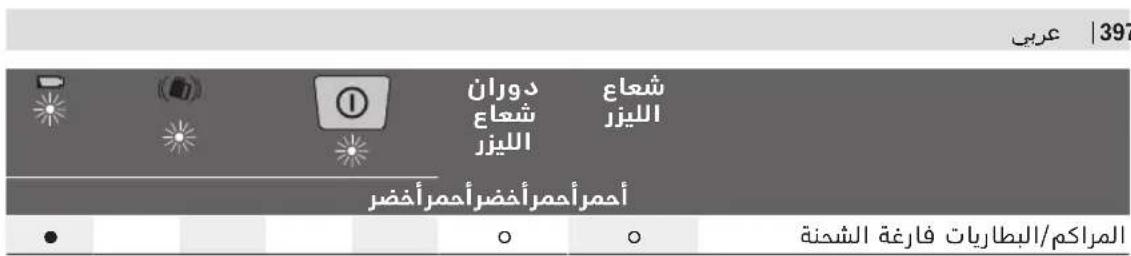
(a>gl aui ju Jlll Jus Lc)jaggllx2y:aj/×2
aagol
auiuJ 0e Jn jalil
aJyIgSsIgOJyIgSsIgSsIgSsIgSsIgSsIgSsIgSsIgSsIgSsIgSsIgSsIgSsIgSsIgSsIgSsIgSsIgSsIgSsIgSsIgSsIgSsIgSsIgSsIgSsIgSsIgS
/psjolgl auiu j0g21 gU 1.ajjaiU Uauu u


:gjg21 slalg jgJb
2012/19/EU 2012/19/EU 2012/19/EU 2012/19/EU 2012/19/EU 2012/19/EU 2012/19/EU 2012/19/EU 2012/19/EU 2012/19/EU 2012/19/EU

doJg JUJI
aIg aI
jag jalwlg woll osc adbji lc bla
jglg jalwlg wll oao paa 15
- aBg aJb aWj aBb aBwgl gLwg 1aol
. aJso slgo gI cAaB slgo pAaW
agaaig sic wll oC agbw ao AaBj
. uJ sUuluall uilg pAoo kJy jUJI
pIaWlUJluwUg LaoJI aO
aal aal alw wll 1e loaal do sa jk yu yu yu yu yu yu yu yu yu yu yu yu yu yu yu yu yu yu yu yu yu yu yu yu yu yu yu yu yu yu yu yu yu yu yu yu yu yu yu yu yu yu yu yu yu yu yu yu yu yu yuuy uau uau uau uau uau uau uau uau uau uau uau uau uau uau uau uau uau uau uau uau uau uau uau uau uau uau uau uau uau uau uau uau uau uau uau uau uau uau uau uau uau uau uau uau uau uau uau uau uau uau uAU UAU UAU UAU UAU UAU UAU UAU UAU UAU UAU UAU UAU UAU UAU UAU UAU UAU UAU UAU UAU UAU UAU UAU UAU UAU UAU UAU UAU UAU UAU UAU UAU UAU UAU UAU UAU UAU UAU UAU UAU UAU UAU UAU UAU UAU UAU UAU UAU UAU UAU
LdclwpoAosBosch jyWu Wlaio gaoa bJlwaai I JI 15 .log
aagU aegg uall Ull g g caiu all p j 1uulg U Jluwau u JluwJ sic qiuJI G u
U
Robert Bosch Morocco SARL
gjoo oo ojjol gjw,53
LJ1J120300
+212529314327:JJI
sav.outillage@ma.bosch.com: 一 _ 1 ^ 一 gj
:doall jglic no jall
www.bosch-pt.com/serviceaddresses
s
Laa aJJJ (Sgj jgj J 1 Sgjj 1000111 g g 1g 1 .
Lgol LsJ GRL300HVG
S u ju gj dolio ojl jil gj 4 a. wl o s h o jduo y o laowl ploim dolio jg joo go .dagj ojl jil j
LwJgwsuJJyJuswCwysaJ1s 4 Wssj (SjIol oJnJgl jI q, CwJ J ggsuJ uJ yOsw JUJ LwJ J sW .Jlssyogos
3R wJ jI jI oJgJ J 1uL pJ .s dgi gws Ujao gUJwUJoo,duu uJgUJoo
S 日 1aw (33)
sui ddoa oogj s Jg (34)
(5jduabdoauggJ (35)
Sdu Usb/ulalso
(A) JJJ O SiiS CJI J (36)
(a)SjOjJaldo (37)
AduU dU 38
(39)
(40)
jgs a cai jg aay uai Joo (41)
5/8"
.
g jai l sjw w
.
gjggbj g jIjI jI jjjw
.
. 1
日 ~ l ~ 山 山 山 山 山 山
jJwJlWJl
A.1|aqj jai|j
.duu uui U Sjus Jgwh jbs jgi
aJLSjJwolssu
.1JusI aLwg juaa Jgoo
oIawI jIw oIswJ I dgi
SuiSig SuiSj JI gJgJU
juaaiao 10
Jl jIwglggs
sui o laowlUg aLw g,JJu
jijl jg jg jbs oos w
.
()UJwU
山LbuooJ5(ojuég aJy,ds
..j j 5gwwuil 5lo
g g jgwwjg yjolswj jl
.
Jg g Ugs
laolj dajggl gslgglg
.1s dgi
olwjolawl jgo
(SJJj
JgUSSuWLoSjI jiljljI
15gac bgb,ulclaljI gaiu uS jS
aigj jsgacblajg jlaialw gbs
.ω|o
g g jg jg jg jg jg jg jg jg jg jg jg jg jg jg jg jg jg jg jg jg jg jg jg jg jg jg jg jg jg jg jg jg jg jg jg jg jg jg jg
| GRL 250 HVGLR 300 HVGLR 300 HVG |
| 3601 K61 6..3 601 K61 5..3 601 K61 7.. |
| | | (BA)(Δ)JLJLJLJLJLJLJLJLJLJLJLJLJLJLJLJLJLJLJLJLJLJLJLJLJLJLJLJLJLJLJLJLJLJLJLJLJLJLJLJLJLJLJLJLJLJLJLJLJLJLJ L |
| 30 m30 m50 m | - |
| 0,5-125 m0,5-150 m0,5-150 m | - |
| (30 m J) ±3 mm | (30 m J) ±3 mm | (30 m J) ±3 mm | (CA)JLJLJLJLJLJLJLJLJLJLJLJLJLJLJLJLJLJLJLJLJLJLJLJLJLJLJLJLJLJLJLJLJLJLJLJLJLJLJLJLJLJLJLJLJLJLJLJLJL J |
| ±8% (±4,6°) | ±8% (±4,6°) | ±8% (±4,6°) | mJLJLJLJLJLJLJLJLJLJLJLJLJLJLJLJLJLJLJLJLJLJLJLJLJLJLJLJLJLJLJLJLJLJLJLJLJLJLJLJLJLJLJLJLJLJLJLJLJLJ |
| 15 s | 15 s | 15 s | JLJLJLJLJLJLJLJLJLJLJLJLJLJLJLJLJLJLJLJLJLJLJLJLJLJLJLJLJLJLJLJLJLJLJLJLJLJLJLJLJLJLJLJLJLJLJLJLJLJ J |
| 150/300/600 min-1 | 150/300/600 min-1 | 150/300/600 min-1 | JLJLJLJLJLJLJLJLJLJLJLJLJLJLJLJLJLJLJLJLJLJ L |
| 10/25/50° | 10/25/50° | 10/25/50° | JLJLJLJLJLJLJLJLJLJLJLJLJLJ L |
| 0°C ... +40°C | -10°C ... +50°C | -10°C ... +50°C | JLJLJLJLJLJLJLJLJLJ L |
| -20°C ... +70°C | -20°C ... +70°C | -20°C ... +70°C | JLJLJLJLJLJLJLJ L |
| 2000 m | 2000 m2000 m | JLJLJLJLJLJLJ L |
| 90 % | 90 % | 90 % | JLJLJLJLJ L |
| 2D) | 2D) | 2D) | JLJLJLJ L |
| 3R | 3R | 2 | JLJLJ L |
| 532 nm, < 5 mW | 635 nm, < 5 mW | 635 nm, < 1 mW | JLJL J |
| 0,4 mrad (JLJL J) | 0,4 mrad (JLJL J) | 0,4 mrad (JLJL J) | JLJ L |
| 5/8"-11 | 5/8"-11 | 5/8"-11 | JLJ L |
| 2 × 1,2 VHR20 (D) (9 Ah) | 2 × 1,2 VHR20 (D) (9 Ah) | 2 × 1,2 VHR20 (D) (9 Ah) | (NiMH) JJL J L J L J L J L J L J L J L J L J L J L J L J L J L J L J L J L J L J L J L J L J L J L J L J L J L J L J L J L J L J L J L J L J L J L J L J L J L J L J L J L J L J L J L J L J L J L J L J L J L J L J J L J L J L J L J L J L J L J L J L J L J L J L J L J L J L J L J L J L J L J L J L J L J L J L J L J L J L J L J L J L J L J L J L J L J L J L J L J L J L J L J L J L J L J L J L J L J L J L J L J I J L J I J L J I J L J I J L J I J L J I J L J I J L J I J L J I J L J I J L J I J L J I J L J I J L J I J L J I J L J I J L J I J L J I J L J I J L J I J L J I J L J I J L J I J L J I J L J I J L J J L J I J L J I J L J I J L J I J L J I J L J I J L J I J L J I J L J I J L J I J L J I J L J I J L J I J L J I J L J I J L J I J L J I J L J I J L J I J L J I J L J I J L J I J L J I J L J I J L JI J L J I J L J I J L J I J L J I J L J I J L J I J L J I J L J I J L J I J L J I J L J I J L J I J L J I J L J I J L J I J L J I J L J I J L J I J L J I J L J I J L J I J L J I J L J I J L J I J L J L J I J L J I J L J I J L J I J L J I J L J I J L J I J L J I J L J I J L J I J L J I J L J I J L J I J L J I J L J I J L J I J L J I J L J I J L J I J L J I J L J I J L J I J L J I J L J I J I J I J I J I J I J I J I J I J I J I J I J I J I J I J I J I J I J I J I J I J I J I J I J I J I J I J I J I J I J I J I J I J I J I J I J I J I J I J I J I J I J I J I J I J I J I J I J I J I J J I J I J I J I J I J I J I J I J I J I J I J I J I J I J I J I J I J I J I J I J I J I J I J I J I J I J I J I J I J I J I J I J I J I J I J I J I J I J I J I J I J I J I J I J I J I J I J I J I JI J I J I J I J I J I J I J I J I J I J I J I J I J I J I J I J I J I J I J I J I J I J I J I J I J I J I J I J I J I J I J I J I J I J I J I J I J I J I J I J I J I J I J I J I J I J I J I J I J I J |
25^ A
u u (dua aiau uui) bua wliol bujw l csa oos
jgso sioj C
()
- jsojla w
sIgjI jO sIoWJgS oJ I JJJiS JSLac (sIg
.ogwlo dgiogjjio jll
(35) 15j1 abao uogjus ju
g uu uuuu (34) uis
JgI J LsJU. 1J J J sJU ddo
gab 151sbsb gao sogai du jau
dgi gj jg jda Cawg g
jIooJgboaawlpoocgos
JgIgJgJLgSjJgSoljIjus
jg jw juii jg w iSoo L yj U g o uu j Sj g sswj Jd
gdu
Sj< ojl jljl jjll
j jil j j j j j j j j j j j j j j j j j j j j j j j j j j j j j j j j j j j j j j j j j j j j j j j j j j j j j j j j j j j j j j j j j j j j j j j j j j j j j j j j j j j j j j j j j j j j j j j j j j j jjjjjjjjjjjjjjjjjjjjjjjjjjjjjjjjjjjjjjjjjjjjjjjjjjjjjjjjjjjjjj
jgl jslol
go asis gilgo jI sIc I J SjS Ogdo .sis cagio ly uSeio I jy sgj y ilg J gJy sl aie gbsw sJy llo y dLo go L aawu no j. dIwuy y ssio jy gij J .si Sj ojl 5ojl 1i j CwU J Ssoogio .dJ
usjoljj1s
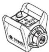
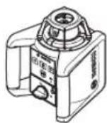
gocuagoo 1000000000000000000000000000000000000000000000000000000000000000000000000000000000000000000000
jjjw jg yol g sis .jai jng
jw jy d a w y 13( jq.)16
Saa j0j 12 (12) jJ JJJJ J J J J J J J J J J J J J
(12) 1jul jw w w g jg jg jg jg jg jg jg jg jg jg jg jg jg jg jg jg jg jg jg jg jg jg jg jg jg jg jg jg jg jg jg jg jg jg jg jg
oLswJjksj
Jgj gaiu ()
4j3ljg3olj1jj
4jIJJgOJjUj
JgLoUwgi LjLjLjLjLjLjLjLjLjLjLjLjLjLjLjLjLjLjLjLjLjLjLjLjLjLjLjLjLjLjLjLjLjLjLjLjLjLjLjLjLjLjLjLjLjLjLjLjLjLjLj LjLjLjLjLjLjLjLjLjLjLjLjLjLjLjLjLj LjLj Lj Lj Lj Lj Lj Lj Lj Lj Lj Lj Lj Lj Lj Lj Lj Lj Lj Lj Lj Lj Lj Lj Lj Lj Lj Lj Lj Lj Lj Lj Lj Lj Lj Lj Lj Lj Lj Lj Lj Lj Lj Lj Lj Lj Lj Lj Lj Lj Lj Lj
[alabai slac]
JU JU JU JU JU JU JU JU JU JU JU JU JU JU JU JU JU JU JU JU JU JU JU JU JU JU JU JU JU JU JU JU JU JU JU JU JU JU JU JU JU JU JU JU JU JU JU JU JU JU JU
![BOSCH GRL 250 HV Professional - [alabai slac] - 1](/content/2026/03/558706/images/1127f465edc94243855eeb2c76679708b8b32e8ddd378fbe2d60f38786c62af6.jpg)
LolaiuSlySlaabajgLaSloLac .siuoiwio (36)jjoi
![BOSCH GRL 250 HV Professional - [alabai slac] - 2](/content/2026/03/558706/images/aaddc19f7ff958a2b9ce7421c7fa635531818113960849c214a29fc4f68e8c95.jpg)
Jusj SjSlae
jS oJl jI jN jN jI jI jI jI JI JI JI JI JI JI JI JI JI JI JI JI JI JI JI JI JI JI JI JI JI JI JI JI JI JI JI JI JI JI JI JI JI JI JI JI JI JI JI JI JI JI JI JI JI JI JI JI JI JI
Slae daa uya du baa slaac aagau cya Ujiis 26)uajua slac daa (5) uja. Jiau jg oJj
SsLac daS L (5) SsLac daS L 1 sLac gj jj j j jg j (11) bJ j u oJ Jj J J J J J J J J J J J J J J J J J J J
da oJg, 0jI jI jI Jw gola c
. ju14 (4) uog/ugol
jla cIw 2jl w y sO jI si IJI ds Og
SgW JbA l U Jg Ssig W Jj GsO Og
SgS oJsi IJI L W Oo W Jf Cclw 2jl
Jlw sl SjU L Lo SjU Jl Cabaloo
SgS oJsi IJI .Gw Go w gola sIlogil jg
Ldo IJg SsD Jg Coggo JoJg
Sjslac Igil
LjSlaeEglgI Lgjo
g gol cgo j slac 3 j j o laiwl .wI JlKo IJjOjJjJgac
Lus
Bim ojg a u jy sJSLac JU OsiCgUjOlaiw JsuIg Loaw .gaw GduogicuJw calao 1sL cJW .qis lail Jpbi Jgo
j j j g j j s l a j j j j g j j d j j j g j j d j j j g j j g j j g j j g j j g j j g j j g j j g j j g j j g j j g j j g j j g j j g j j g j j g j j g j j g
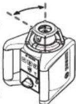
SgwhJbai SjLac
Csw jIbJ slac Jqso sOjJil JjI LsOjJsl JjU wjj U cog g oJg OJ Cgo J Sduji jl jj Ew uJzJl JjU koo JJU d Ua jgrjl dau Jg Uo J .si G y
ds: gw jbsj j/ jg jjai jw. d jw (2) gw jbls 1 gw o jw j w dy sio jgb (1) gw jw n w gj j u30 gsw jbls .gw o jw gsw jbls
Sj jil jj j:Jg C Jg Jb1
Cusog j 1 j sui jj C O gdo j
jbls,si C u j Sdy Sw y Dg
Gagio ljju jy Gsw y Ue g
(3) Cugog jilui ,ij Gao jj gj Dg
(1) SGJlui w g
.
(2)gw jbaI daS, gw jbaI u w Jg W JbIa I aai dssu (28) gw Jjg sgw oegw giJ sgw JbaI sJSLAC 4. siL GgW uJy JgJ LjU yJsi Jliwi) sgw jji OJsi JjJd siOo 40oog JxJy JyJgB (3) Coo g JxJy EgW oA D SsLac egi JjI Jg W .siG
suiis jgao abai jjul gijcagogigil gajgoojol jgljuljlgai
L sLac jI SgW JbA l n g y Bgolg 2 (2) SgW JbA dS u w g jUuJ (28) SgW JbA dS u w g jUuJ (29) 2j u uJ uuJ uuJ uuJ uuJ uuJ uuJ uuJ uuJ uuJ uuJ uuJ uuJ uuJ uuJ uuJ uuJ uuJ uuJ uuJ uuJ uuJ uuJ uuJ uuJ uuJ uuJ uuJ uuJ uuJ uuJ uuJ uuJ uuJ uu
JbIa dss: gw JbIa SsLae nJgS wgo I bIa UgUg UgUg UgUg UgUg UgUg UgUg UgUg UgUg UgUg UgUg UgUg UgUg UgUg UgUg UgUg UgUg UgUg UgUg UgUg UgUg UgUg UgUg UgUg UgUg UgUg UgU
sIac uIgi jgolj Ujiss alwga dsi Jglgo sJ gola l wg j Sgwh bal .Egogj1uWlqjSb
jJljljjl jis
Joc 0s jis jolgc
gaa 1s Jb slo ju uuiu 1j jgl gjj sllg jco kba y sls lal .aik
jil jui jujjlos abw dla jil j oji ci jiyi jil jil yu wai jui 20 syl
jgbi0 (J)10(jcwsLj
jI jg oJ jI jus L Js Jy Ogs G 100000000000000000000000000000000000000000000000
(5)gac cgo go J Lwaia daa

jgduS Egej) jLjB(
jglgo jg ojl jj gac cuogos j iis syl u aao u jl baaabai Sj glgo jlp l naiaalw siool
%oogaa8.ajjagac jga
Ldoa Lclw slu aac uui jilj 1
Uclw (slo uac gjI)29olj j UjiS (sg) .Ju
aoss, cclw slu jae 1j sila y slj Cclw slu aje 1j j 30 (
logil jji
gj
Ugol Uoog OJgagbOg oJil jIjU
Uu uog 5U.oo Go yauuui Ugac
Ugol oJsi JjU gocg Ooog
GosuJgao slJjUuSgola
uK
ggo g ojol jj l jw g jl w 1111111111111111111111111111111111111111111111
4,6.1s jss jsg
jw 3) Cg jilwi yjj jj pokim .sij g kai jui juj g kaiy d g siaa jbj (3) cag jilwi aai yd ojl jilu w u w jil g jw g jul g jul g jul g jul g jul g jul g jul g jul g jul g jul g jul g jul g jul g jul g jul g jul g jul g jul g jul g jul g
jI jI JJ 8% jI jI jI jI jI jI jI jI jI jI jI jI jI jI jI jI jI jI jI jI jI jI jI jI jI jI jI jI jI jI jI jI jI jI jI jI jI jI jI jI jI jI jI jI jI jI jI jI jI jI j1 g o s a s s s s s s s s s s s s s s s s s s s s s s s s s s s s s s s s s s s s s s s s s s s s s s s s s s s s s s s s s s s s s s s s s s s s s s s
g jg cgo jgl gjg jgl jgl jgl jgl jgl jgl jgl jgl jgl jgl jgl jgl jgl jgl jgl jgl jgl jgl jgl jgl jgl jgl jgl jgl jgl jgl jgl jgl jgl jgl jgl jgl jgl jgl jgl jgl jgl jgl jgl jgl jgl jgl jgl jgl jgl jgl jgl jgl jgl jgl j
LgUgOgJgJgOjIgJgJgJ gOgOgOgOgOgOgOgOgOgOgOgOgOgOgOgOgOgOgOgOgOgOgOgOgOgOgOgOgOgOgOgOgOgOgOgOgOgOgOgOgOgOgOgOgOgOgOgOgOgOgO
sJg jSj g 0o jS oJl jS Jg
Sj g jI j Sg oJl jI jI jI jI
.90° Jdoo y Sj OJl
J30 sOJl JI JI
:JU
abj jy d aai .30 m x +0,1 mm/m = ±3 mm 5j8 ojl jg g j j j j j j j j j j j j j j j j j j j j j j j j j j j j j j j j j j j j j j j j j j j j j j j j j j j j j j
Lac [slaiim]
jbl abai bwgjl glaiooIc qg oJgam g dlol juiu .siS o laowll jlu bla u jl lsliguiqoiog jjdl abai ojl iLgluo .siU go jui
(C
w Cwai jil jil jil wgjl uu
WM4JgdscuaiuLjSJS (Dgaaes
jJlgl jSg oJljl Jlgl gLoaw jI slk wai (42)Jlgdu wai yag (59) JI Jlgdu wai yag (44) 5/8" ag jgbio ay Sg oJljl Jlgl sgj (21) aL dw JwJwJw
Sjglgo jlgysd yai:glssdywai L aL dW gaijl glgaiJds Lwsio JyBaw Ss (5g) as Lwlsu suiy jsiu G aoggi, glo piai dU w nuiu u g sy
Jds LgBwgi 1j (42) jgs dy wzi g
pSoo jgs dy, sjjls jje (40) Juail slg jgw
pSoo jgi Sgj (39) Juail dUw g dy uis
jgb dy Jssao la ijgds dy wai jg.
jgb dy ds uis Cg g uis wai jgds dy sgac
. gsw ow pSoo g cu
yai yu gj y la w aydu u (5g)
j41dydu w uai l jui j (42) jus d
jui dydu w (5g) ojui jui c
duo jds uolks yogd uui egi
yo aogj sglj jia jao da u ciuy
gabw jsj jksol jgl g ojl j1 j 0g
gaa 20da jla
gluo jg duiu100Lo uugy
Lulu laljai du cuiu xilg20u g u jio
oLswd bgojo UgjU jLs JcL sygi (dyw gilj Lj sla)
gjw jj gjbiu a.igw 12gj
jus jjssjjj 1s
jI SjB jSjS oJlsljI jI sIa bJjO aJi Jg jI j (oJla) Iba jIoo JI JI JI JI JI OJSLJJI
gBosch.sis
guluaggo jjui Cus
juiab1 1g g gds dus jgbdo u 30s
gjglg jIoo gosoooogj ggl joo oJ 30
| jswjwyyjw | |
| ● | ● |
| 2×/s |
| ● |
| ● |
| ● |
| ● |
| ● |
| 2×/s | ○ |
| 2×/s | ○ |
| ● | ● |
g120slaoc: (a1t,2rjglgJia s) 2sj Saa2csw:2x/s
yJUosBoschjuaaOogjS 1wLulaleo g Ugao ojuu law LgW
J 10 J 10
wJyJyJyJyJyJyJyJyJyJyJyJyJyJyJyJyJyJyJyJyJyJyJyJyJyJyJyJyJyJyJyJyJyJyJyJyJyJyJyJyJyJyJyJyJyJyJyJyJyJyJ yJy J 1994834571 J42039800+uJI
:dua dols Jj jolss jw www.bosch-pt.com/serviceaddresses
uugw9 CJ1o
olkwsjg jai gmasi j
JgdsoljI jusg jjw, g oJ slj Jl aawu .sJ sOJI Jau
JJJg oJ jI jusg jjw, g oJ slj Jl J
. g abge cI lo JUw Lg
g pJ Ulaaw Sj I ggl JJSg
g Oogw slgo nJy JSLj .Sis Olaaw Ugbjo
. gis (S) 10g
JJgjaiaogbwogdy Sg oJ slj J
agj abj nn jg g xis jaiio g yjo gblj
. slai olaaw jjngy Jlaaewjl dss
juiu L o jglua g lo