
GLL 210 Professional - Laser pointer BOSCH - Free user manual and instructions
Find the device manual for free GLL 210 Professional BOSCH in PDF.
| Product Type | Laser line pointer |
| Brand | Bosch |
| Model | GLL 210 Professional |
| Minimum Range | 10 m |
| Leveling Accuracy | ±0.3 mm/m |
| Self-leveling Range | ±4° |
| Leveling Time | < 4 s |
| Operating Temperatures | -10 °C to +50 °C |
| Storage Temperatures | -20 °C to +70 °C |
| Max Relative Humidity | 90 % |
| Laser Class | 2 |
| Laser Type | 630-650 nm, < 1 mW |
| Divergence | 0.5 mrad (full angle) |
| Tripod Mount | 1/4" and 5/8" |
| Power Supply | 3 batteries 1.5 V LR6 (AA) |
| Battery Life - Cross-line Mode | 9 h |
| Battery Life - Line Mode | 17 h |
| Weight (according to EPTA) | 0.49 kg |
| Dimensions (L x W x H) | 112 x 55 x 106 mm |
| Protection Rating | IP54 |
| Operating Modes | Cross-line, horizontal, vertical |
| Special Features | Self-leveling, automatic shut-off (120 min), locked pendulum unit |
| Included Accessories | Swivel mount RM 1, protective case, laser target, laser viewing glasses (depending on version) |
| Maintenance | Clean with soft damp cloth, no solvents |
| Repairability | Spare parts available, Bosch after-sales service |
Frequently Asked Questions - GLL 210 Professional BOSCH
User questions about GLL 210 Professional BOSCH
0 question about this device. Answer the ones you know or ask your own.
Ask a new question about this device
Download the instructions for your Laser pointer in PDF format for free! Find your manual GLL 210 Professional - BOSCH and take your electronic device back in hand. On this page are published all the documents necessary for the use of your device. GLL 210 Professional by BOSCH.
USER MANUAL GLL 210 Professional BOSCH
GLL 2-10 Professional
Robert Bosch Power Tools GmbH
70538 Stuttgart
GERMANY
www.bosch-pt.com
1609 92A7AN(2021.12)T/533

de Originalbetriebsanleitung
en Original instructions
fr Notice originale
es manuaal original
pt Manual original
1.1.1.1.1
HI Oorspronkelijke gebruksaanwijzng
da Original brugsanvishing
SV Bruksanvisning original
no Original drittsir
f Alkuperaisel ojeel
elItpototuro oBnyTayxphorc
Original isletmetallmati
pl Instrukcja oryginalina
cs Puvodni navod k pouzivani
sk Povodny navod na pouzite
hu Eredeti hasznalatiutasitas
ruOpHHaJIbHOe pyKo5OdCTBO NO 3KcNpyatauHa
uk OumriHabHa HcTpykui 3 ekCnpyatauui
kk Pnndanany hckaynbfbbltnhyckacb
ka m6ogog6gogjlu3gogogogoo
0647671300
ro instruetioni originale
bgOpHnHaHa HhctpyKn
mkOpHHHAnHOyNAcTBO3a paBota
sr Originalno uputstvo zarad
slzvima navodila
hr Originalne upoute za rad
et Alguparane kasutusjuhend
Instrukcijas originalvaloda
It Original instrukcia
ja才尼尔取报说明
zh正本使用说明书
zh原始使用説明号
ka
thnnnne nnnnne
id Petuniuk-Petuniuk untuk Penggunaan Orisinal
viBan goc houng dan su'dung
ar,dy,dyw
fa 1ol slai0j

Deutsch.. 9
English 22
Francais 36
Espanol. Pagina 50
Portugués Pagina 64
Italiano 77
Nederland. 91
Dansk . 104
Svensk Sidan 117
Norsk. Side 129
Suomi Sivu 142
EAAynvka 155
Türkce. Sayfa 168
Polski. Strona 184
Čestina Stranka 198
Slovencina Stranka 211
Magyar .Oldal 223
Pycckn ..CtpaHua 237
YkpaiHcbKa CtopiHa 252
Ka3ak . 267
Johnoymo 83.281
Romana.. 296
BbIrapckn .CtpaHua 310
MaKeDoHcKn. 324
Srpski Strana 338
Slovenscina Stran 351
www.bosch-pt.com/serviceaddresses
22 | English
Entsorgung
All instructions must be read and observed in order for the measuring tool to function safely. The safeguards integrated into the measuring tool may be compromised if the measuring tool is not used in accordance with these instructions. Never make warning signs on the measuring tool unrecognisable. SAVE THESE IN
STRUCTIONS FOR FUTURE REFERENCE AND INCLUDE THEM WITH THE MEASURING TOOL WHEN TRANSFERRING IT TO A THIRD PARTY.
Warning! If operating or adjustment devices other than those specified here are used or other procedures are carried out, this can lead to dangerous exposure to radiation.
The measuring tool is delivered with a laser warning sign (marked in the illustration of the measuring tool on the graphics page).
If the text of the laser warning label is not in your national language, stick the provided warning label in your national language over it before operating for the first time.

Do not direct the laser beam at persons or animals and do not stare into the direct or reflected laser beam yourself. You could blind somebody, cause accidents or damage your eyes.
If laser radiation hits your eye, you must close your eyes and immediately turn your head away from the beam.
Do not make any modifications to the laser equipment.
- Do not use the laser goggles (accessory) as protective goggles. The laser goggles make the laser beam easier to see; they do not protect you against laser radiation.
- Do not use the laser goggles (accessory) as sunglasses or while driving. The laser goggles do not provide full UV protection and impair your ability to see colours.
Have the measuring tool serviced only by a qualified specialist using only original replacement parts. This will ensure that the safety of the measuring tool is maintained.
- Do not let children use the laser measuring tool unsupervised. They could unintentionally blind themselves or other persons.
- Do not use the measuring tool in explosive atmospheres which contain flammable liquids, gases or dust. Sparks may be produced inside the measuring tool, which can ignite dust or fumes.
Keep the measuring tool and the magnetic accessories away from implants and other medical devices, e.g. pacemakers or insulin pumps. The magnets inside the measuring tool and accessories generate a field that can impair the function of implants and medical devices.
- Keep the measuring tool and the magnetic accessories away from magnetic data storage media and magnetically sensitive devices. The effect of the magnets inside the measuring tool and accessories can lead to irreversible data loss.
Product Description and Specifications
Please observe the illustrations at the beginning of this operating manual.
Intended Use
The measuring tool is intended for determining and checking horizontal and vertical lines.
The measuring tool is suitable for indoor and outdoor use.
24 | English
Product Features
The numbering of the product features shown refers to the illustration of the measuring tool on the graphic page.
(1) Laser beam outlet aperture
(2) On/off switch
(3) 5 / 8'' tripod mount
(4) 1 / 4'' tripod mount
(5) Vertical mode button
(6) Horizontal mode button
(7) Status indicator
(8) Pendulum lock indicator
(9) Laser warning label
(10) Serial number
(11) Battery compartment cover
(12) Battery compartment cover locking mechanism
(13) Rotating mount (RM 1)a
(14) Guide rail
(15) Fastening slot
(16) Magneta)
(17) Guide groove
(18) Ceiling clip (BM 3)a
(19) Universal holder (BM 1)a)
(20) Laser target platea)
(21) Protective bag
(22) Laser viewing glassesa)
(23) Tripod (BT 150)a
(24) Telescopic shaft (BT 350)a
a) Accessories shown or described are not included with the product as standard. You can find the complete selection of accessories in our accessories range.
Technical Data
| Line laser GLL 2-10 | |
| Article number | 3601 K63 L.. |
| Working range at leastA) | 10 m |
| Levelling accuracy ±0.3 mm/m | |
| Typical self-levelling range ±4° | |
| Typical levelling time < 4 s | |
| Operating temperature -10 °C to +50 °C | |
| Storage temperature -20 °C to +70 °C | |
| Max. altitude 2000 m | |
| Relative air humidity max. 90 % | |
| Pollution degree according to IEC 61010-1 2 | B) |
| Laser class 2 | |
| Laser type 630-650 nm, < 1 mW | |
| C6 | 1 |
| Divergence 0.5 mrad (full angle) | |
| Tripod mount 1/4"; 5/8" | |
| Batteries 3 × 1.5 V LR6 (AA) | |
| Operating duration in operating mode | |
| - Cross-line mode | 9 h |
| - Line mode | 17 h |
| Weight according to EPTA-Procedure 01:2014 | 0.49 kg |
| Dimensions (length × width × height) | 112 × 55 × 106 mm |
| Protection rating IP54 (dust and splash-proof) | |
A) The working range may be reduced by unfavourable environmental conditions (e.g. direct sunlight).
B) Only non-conductive deposits occur, whereby occasional temporary conductivity caused by condensation is expected.
The serial number (10) on the type plate is used to clearly identify your measuring tool.
Assembly
Inserting/changing the batteries
It is recommended that you use alkaline manganese batteries to operate the measuring tool.
To open the battery compartment cover (11), press on the locking mechanism (12) and remove the battery compartment cover. Insert the batteries.
When inserting the batteries, ensure that the polarity is correct according to the illustration on the inside of the battery compartment.
If the batteries become weak, the status indicator (7) will flash. The measuring tool can still be operated for approximately 1 hour after the first flash.
Always replace all the batteries at the same time. Only use batteries from the same manufacturer and which have the same capacity.
Take the batteries out of the measuring tool when you are not using it for a prolonged period of time. The batteries can corrode and self-discharge during prolonged storage in the measuring tool.
Working with the RM 1 rotating mount (see figures A-B)
Using the rotating mount (13), you can rotate the measuring tool 360^ . This enables you to set up the laser lines precisely, without having to change the position of the measuring tool.
Place the measuring tool with the guide groove (17) on the guide rail (14) of the rotating mount (13) and slide the measuring tool all the way onto the platform.
To disconnect the measuring tool, pull it off the rotating mount in the opposite direction.
Rotating mount positioning options:
- Standing on a flat surface,
Screwed to a vertical surface, - On metallic ceiling strips using the ceiling clip (18),
-
On metallic surfaces using the magnets (16).
-
Keep your fingers away from the rear side of the magnetic accessory while attaching the accessory to surfaces. The strong pulling force of the magnets may jam your fingers.
Operation
Starting Operation
Protect the measuring tool from moisture and direct sunlight.
- Do not expose the measuring tool to any extreme temperatures or fluctuations in temperature. For example, do not leave it in a car for extended periods of time. If it has been subjected to significant fluctuations in temperature, first allow the measuring tool to adjust to the ambient temperature and then always carry out an accuracy check before continuing work (see "Accuracy Check of the Measuring Tool", page 29). The precision of the measuring tool may be compromised if exposed to extreme temperatures or fluctuations in temperature.
Avoid substantial knocks to the measuring tool and avoid dropping it. Always carry out an accuracy check before continuing work if the measuring tool has been subjected to severe external influences (see "Accuracy Check of the Measuring Tool", page 29).
Switch the measuring tool off when transporting it. The pendulum unit is locked when the tool is switched off, as it can otherwise be damaged by big movements.
Switching On/Off
To switch on the measuring tool, slide the on/off switch (2) to the "On" position (for working with the pendulum lock) or to the "On" position (for working with automatic levelling). The status indicator (7) lights up. As soon as it is switched on, the measuring tool emits laser lines from the outlet apertures (1).
- Do not direct the laser beam at persons or animals and do not stare into the laser beam yourself (even from a distance).
To switch off the measuring tool, slide the on/off switch (2) to the "Off" position. The status indicator (7) goes out. The pendulum unit is locked when the tool is switched off.
- Never leave the measuring tool unattended when switched on, and ensure the measuring tool is switched off after use. Others may be blinded by the laser beam.
If the maximum permitted operating temperature of 50^ is exceeded, the tool shuts down to protect the laser diode. Once it has cooled down, the measuring tool is operational again and can be switched back on.
Automatic shut-off
If no button on the measuring tool is pressed for approx. 120 min, the measuring tool will automatically switch itself off to preserve battery life.
28 | English
To switch the measuring tool back on after it has been automatically switched off, you can either slide the on/off switch (2) to the "Off" position first and then switch the measuring tool back on, or press either the vertical mode button (5) or the horizontal mode button (6) once.
To deactivate automatic shut-off, hold down the horizontal mode button (6) for at least three seconds (with the measuring tool switched on). If automatic shut-off is deactivated, the laser lines will flash briefly as confirmation.
Note: If the operating temperature exceeds 45^ , automatic shut-off can no longer be deactivated.
To activate the automatic shut-off function, switch the measuring tool off and on again.
Operating Modes
The measuring tool has several operating modes, which you can switch between at any time:
- Cross-line mode (see figure C): Generates one horizontal and one vertical laser line
- Horizontal mode (see figure D): Generates one horizontal laser line
- Vertical mode (see figure E): Generates one vertical laser line
After switching on, the measuring tool is in cross-line operating mode. Using the buttons for horizontal mode (6) and vertical mode (5), you can switch the horizontal and vertical laser lines on and off independently of one another.
All operating modes can be selected with both automatic levelling or the pendulum lock.
Automatic Levelling
Working with automatic levelling
Position the measuring tool on a level, firm surface or attach it to the rotating mount (13) or the tripod (23).
For work with automatic levelling, slide the on/off switch (2) to the "On" position.
The automatic levelling function automatically compensates irregularities within the self-levelling range of ± 4^ . The levelling is finished as soon as the laser lines stop moving.
If automatic levelling is not possible, e.g. because the surface on which the measuring tool stands deviates by more than 4^ from the horizontal plane, the laser beams will flash quickly.
If this is the case, set up the measuring tool in a level position and wait for the self-levelling to take place. As soon as the measuring tool is within the self-levelling range of ± 4^ , the laser beams will light up continuously.
In case of ground vibrations or position changes during operation, the measuring tool is automatically levelled again. Upon levelling, check the position of the laser beams with regard to the reference points to avoid errors arising from a change in the measuring tool's position.
Working with the pendulum lock
For work with the pendulum lock, slide the on/off switch (2) to the "On" position. The pendulum lock indicator (8) lights up red and the laser lines continuously flash slowly. For work with the pendulum lock, automatic levelling is switched off. You can hold the measuring tool freely in your hand or place it on a sloping surface. This means that the laser beams are no longer levelled and no longer necessarily run perpendicular to one another.
Accuracy Check of the Measuring Tool
Influences on Accuracy
The largest influence is exerted by the ambient temperature. In particular, temperature differences that occur from the ground upwards can refract the laser beam.
In order to minimise thermal influences resulting from heat rising from the floor, it is recommended that you use the measuring tool on a tripod. In addition, position the measuring tool in the centre of the work surface, wherever this is possible.
In addition to external influences, device-specific influences (e.g. falls or heavy impacts) can also lead to deviations. For this reason, check the levelling accuracy each time before beginning work.
First check the height accuracy and levelling accuracy of the horizontal laser line, then the levelling accuracy of the vertical laser line.
Should the measuring tool exceed the maximum deviation during one of the tests, please have it repaired by a Bosch after-sales service.
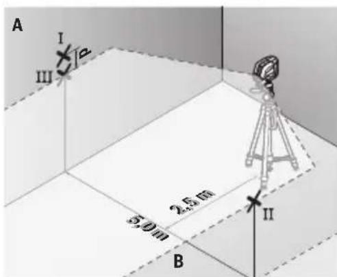
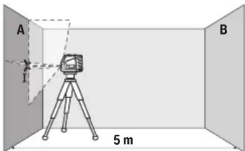
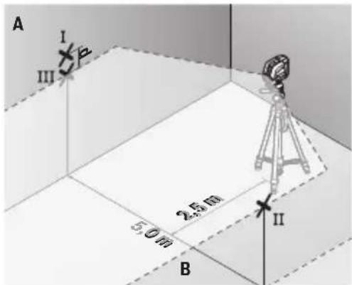
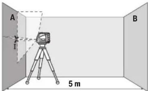
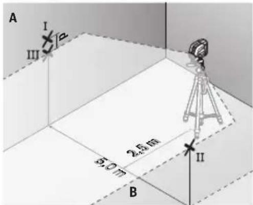
Checking the Height Accuracy of the Horizontal Line
For this check, you will need a free measuring distance of 5m on firm ground between two walls (designated A and B).
- Mount the measuring tool close to wall A on the holder or a tripod, or place it on a firm, level surface. Switch on the measuring tool with the automatic levelling function enabled and select cross-line mode.
30 | English
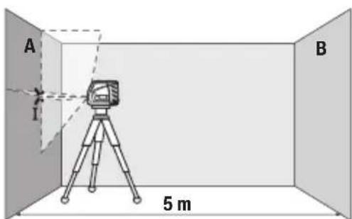
- Aim the laser at the closer wall A and allow the measuring tool to level in. Mark the middle of the point at which the laser lines cross on the wall (point I).
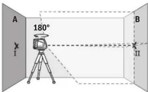
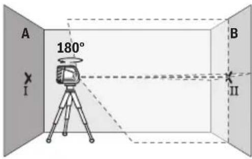
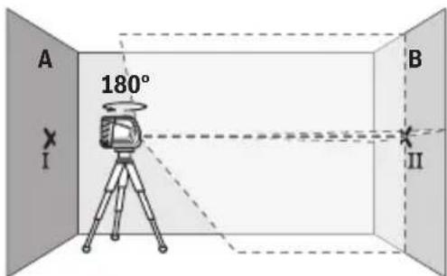
Turn the measuring tool 180^ allow it to level in and mark the point where the laser lines cross on the opposite wall B (point II).
- Position the measuring tool - without rotating it - close to wall B, switch it on and allow it to level in.
- Align the height of the measuring tool (using the tripod or by placing objects underneath as required) so that the point where the laser lines cross exactly hits the previously marked point II on wall B.
-
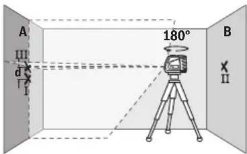
Turn the measuring tool 180^ without adjusting the height. Aim it at wall A such that the vertical laser line runs through the already marked point I. Allow the measuring tool to level in and mark the point where the laser lines cross on wall A (point III).
-
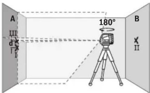
The discrepancy d between the two marked points I and III on wall A reveals the actual height deviation of the measuring tool.
The maximum permitted deviation on the measuring distance of 2 × 5m = 10m is as follows:
10m× ± 0.3mm / m = ± 3mm . The discrepancy d between points I and III must therefore amount to no more than 3mm
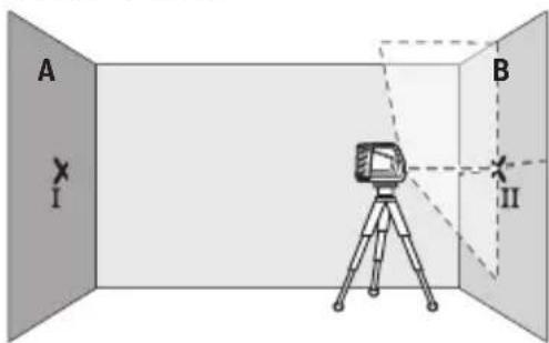
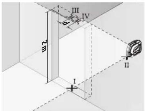
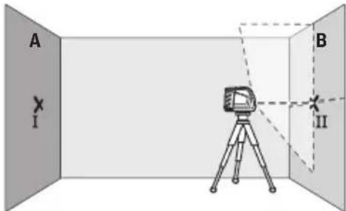
Checking the Level Accuracy of the Horizontal Line
For this check, you will need a free area of 5 × 5m .
- Mount the measuring tool in the middle between walls A and B on the holder or a tripod, or place it on a firm, flat surface. Switch on the measuring tool with the automatic levelling function enabled and select horizontal mode. Allow the measuring tool to level in.
- At a distance of 2.5m from the measuring tool, mark the centre of the laser line on both walls (point I on wall A and point II on wall B).
-
Set up the measuring tool at a 5 m distance and rotated by 180^ and allow it to level in.
-
Align the height of the measuring tool (using the tripod or by placing objects underneath as required) so that the centre of the laser line exactly hits the previously marked point II on wall B.
- Mark the centre of the laser line on wall A as point III (vertically above or below point I).
32 | English
- The discrepancy d between the two marked points I and III on wall A reveals the actual horizontal deviation of the measuring tool.
The maximum permitted deviation on the measuring distance of 2 × 5m = 10m is as follows:
10m× ± 0.3mm / m = ± 3mm . The discrepancy d between points I and III must therefore amount to no more than 3mm
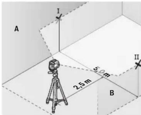
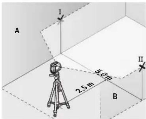
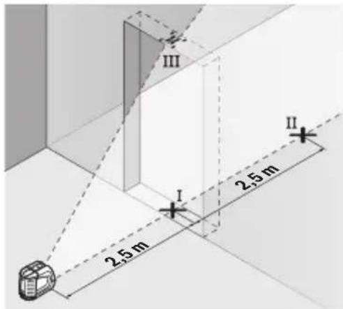
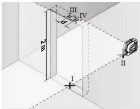
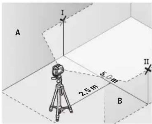
Checking the Level Accuracy of the Vertical Line
For this check, you will need a door opening (on solid ground) which has at least 2.5m of space either side of the door.
- Place the measuring tool 2.5m away from the door opening on a firm, flat surface (not on a tripod). Switch on the measuring tool in the mode with automatic levelling. Select vertical mode and allow the measuring tool to level in.
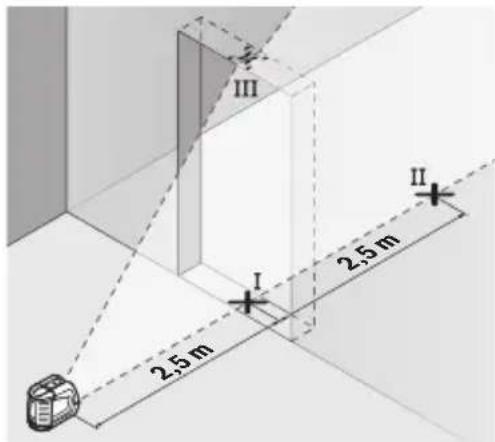
- Mark the centre of the vertical laser line on the floor of the door opening (point I), 5m away on the other side of the door opening (point II) and on the upper edge of the door opening (point III).
-
Set up the measuring tool on the other side of the door opening, directly behind point II. Allow the measuring tool to level in and align the vertical laser line in such a way that its centre passes through points I and II exactly.
-
Mark the centre of the laser line on the upper edge of the door opening as point IV.
-
The discrepancy d between the two marked points III and IV reveals the actual vertical deviation of the measuring tool.
-
Measure the height of the door opening.
You can calculate the maximum permitted deviation as follows:
Doubled height of the door opening × 0.3mm / m
Example: At a door opening height of 2m , the maximum deviation amounts to
2 × 2m × ± 0.3mm/m = ± 1.2mm . The points III and IV must therefore be no further
than 1.2mm from each other.
Working Advice
- Only the centre of the laser line must be used for marking. The width of the laser line changes depending on the distance.
Working with the Laser Target Plate
The laser target plate (20) improves visibility of the laser beam in unfavourable conditions and at greater distances.
The reflective surface of the laser target plate (20) improves visibility of the laser line.
The transparent surface enables the laser line to be seen from behind the laser target plate.
Working with the Tripod (Accessory)
A tripod offers a stable, height-adjustable support surface for measuring. Place the measuring tool with the 1/4'' tripod mount (4) on the thread of the tripod (23) or a conventional camera tripod. Use the 5/8'' tripod mount (3) to secure the measuring tool on a conventional building tripod. Tighten the measuring tool using the locking screw of the tripod.
Roughly align the tripod before switching on the measuring tool.
Securing with the universal holder (accessory) (see figure F)
You can secure the measuring tool, for example, on vertical surfaces or magnetisable materials using the universal holder (19). The universal holder is also suitable for use as a floor stand and facilitates the height adjustment of the measuring tool.
- Keep your fingers away from the rear side of the magnetic accessory while attaching the accessory to surfaces. The strong pulling force of the magnets may jam your fingers.
Roughly align the universal holder (19) before switching on the measuring tool.
Laser Goggles (Accessory)
The laser goggles filter out ambient light. This makes the light of the laser appear brighter to the eye.
Do not use the laser goggles (accessory) as protective goggles. The laser goggles make the laser beam easier to see; they do not protect you against laser radiation.
34 | English
Do not use the laser goggles (accessory) as sunglasses or while driving. The laser goggles do not provide full UV protection and impair your ability to see colours.
Example applications (see figures F-H)
Examples of possible applications for the measuring tool can be found on the graphics pages.
Maintenance and Service
Maintenance and Cleaning
Keep the measuring tool clean at all times.
Never immerse the measuring tool in water or other liquids.
Wipe off any dirt using a damp, soft cloth. Do not use any detergents or solvents.
The areas around the outlet aperture of the laser in particular should be cleaned on a regular basis. Make sure to check for lint when doing this.
Only store and transport the measuring tool in the protective pouch (21).
If the measuring tool needs to be repaired, send it off in the protective pouch (21).
After-Sales Service and Application Service
Our after-sales service responds to your questions concerning maintenance and repair of your product as well as spare parts. You can find explosion drawings and information on spare parts at: www.bosch-pt.com
The Bosch product use advice team will be happy to help you with any questions about our products and their accessories.
In all correspondence and spare parts orders, please always include the 10-digit article number given on the nameplate of the product.
Malaysia
Robert Bosch Sdn. Bhd.(220975-V) PT/SMY
No.8A,Jalan 13/6
46200 Petaling Jaya
Selangor
Tel.: (03) 79663194
Toll-Free: 1800 880188
Fax: (03) 79583838
E-Mail: kiathoe.chong@my.bosch.com
www.bosch-pt.com.my
Great Britain
Robert Bosch Ltd. (B.S.C.)
P.O.Box 98
Broadwater Park
North Orbital Road
Denham Uxbridge
UB95HJ
At www.bosch-pt.co.uk you can order spare parts or arrange the collection of a product in need of servicing or repair.
Tel. Service: (0344) 7360109
E-Mail: boschservicecentre@bosch.com
You can find further service addresses at:
www.bosch-pt.com/serviceaddresses
Disposal
Measuring tools, accessories and packaging should be recycled in an environmentally friendly manner.
Do not dispose of measuring tools or batteries with household waste.
Only for EU countries:
According to the Directive 2012/19/EU, measuring tools that are no longer usable, and according to the Directive 2006/66/EC, defective or used battery packs/batteries, must be collected separately and disposed of in an environmentally correct manner.
Only for United Kingdom:
According to Waste Electrical and Electronic Equipment Regulations 2013 (2013/3113) and the Waste Batteries and Accumulators Regulations 2009 (2009/890), measuring tools that are no longer usable must be collected separately and disposed of in an environmentally friendly manner.
Français
Robert Bosch Morocco SARL 53, Rue Lieutenant Mahroud Mohamed
20300 Casablanca
Tel.: +212529314327
E-Mail: sav.outillage@ma.bosch.com
France
Robert Bosch (France) S.A.S.
www.bosch-pt.com/serviceaddresses
Calle Robert Bosch No. 405
C.P. 50071 Zona Industrial, Toluca - Estado de Mexico
Tel.: (52) 55 528430-62
Tel.: 800 6271286
www.bosch-pt.com/serviceaddresses
Eliminación
www.bosch-pt.com/serviceaddresses
Eliminação
Livella laser a linee GLL 2-10
www.bosch-pt.com/serviceaddresses
Smaltimento
www.bosch-pt.com/serviceaddresses
Afvalverwijdering
Bosch Service Center
Telegrafvej 3
2750 Ballerup
På www.bosch-pt.dk kan der online bestilles reservedele eller oprettes en reparations ordre.
TIf. Service Center: 44898855
Fax: 44898755
E-Mail: vaerktoej@dk.bosch.com
www.bosch-pt.com/serviceaddresses
Bortskaffelse
Bosch Service Center
Telegrafvej 3
2750 Ballerup
Danmark
Tel.: (08) 7501820 (inom Sverige)
Fax: (011) 187691
Du hittar fler kontaktuppgifter till service har:
www.bosch-pt.com/serviceaddresses
Avfallshantering
www.bosch-pt.com/serviceaddresses
Kassering
www.bosch-pt.com/serviceaddresses
Hävitis
www.bosch-pt.com/serviceaddresses
Anoupon
Ta opyava etponanc, ta eapntmuata kai ooukeuaoic npenei va avakukawovtai me tpoio pfikokpoc to nepiaaov.
Mn pixveTe Ta opyava metpnonc kalic natapiec oiaikak anoppipmuata!
Movi yia xwpec tnc EE:
www.bosch-pt.com/serviceaddresses
Tasfiye
Robert Bosch Sp. z o.o.
www.bosch-pt.com/serviceaddresses
Utylizacja odpadów
Cárovy laser GLL 2-10
Bosch Service Center PT
K Vapence 1621/16
692 01 Mikulov
www.bosch-pt.com/serviceaddresses
Likvidace
www.bosch-pt.com/serviceaddresses
Likvidácia
Vyrobok, prisluşenstvo a obal treba daf na recykláciu šetriacuŽivotné prostredie.
Mérici prístroje a baterie nevyhazujte do domovniho opadu!
Len pre krajiny EU:
Podla europsekj smernice 2012/19/EU sa uz nepouzite'né elektrické meracie pristroje a podla europsekj smernice 2006/66/ES sa poskodené alebo vybité akumúláry/batérie musia zbierat separovane a odovzdat na recykláciu v sulade s ochranouŽivotného prostredia.
Magyar
www.bosch-pt.com/serviceaddresses
Hulladékkezelés
PekomeHdyETcOuHCTHTb HNCTpyMeHT OT nbIN NocLe KaKdoRo HCNoB30BaHHa.
XpaheHne
-Heo6xOIMO XpaHb B CyXOM MeCTe
- Heo6xOIMO XpaHnTb BdaIOn OT NCTOCHNKOB IOBblIeHHbIX TeMpepaTp I BO3deiCTBnA COJIHeuHbIX lyuei
- npxpaHenn Heo6xoJMo H36eraTb pe3Koro nepenaTaemepaTy
-eCNHn HNCTpyMeHT NOCTaBnEeTcB MRAKO CymKe NIN PnactNKOBOM KeIce peKOMeHN dyETcXpaHnTB HNCTpyMeHT B 3TOI 3aunTHoYnaKOBKe
- noipobhble Tpe6oBaHnK yCIOBnM xpaHeHn CMOtpnte B FOCT 15150-69 (YcnoBne 1)
TpaHcnpOpBka
- KaTeOpHueCKn He IOnyckaTcra NaeHne N IIO6bIe MexaHnueCKHe BO3JeCTBna Ha yNaKOBky npH TpaHCnpTnpOBke
- npn pa3rpy3ke/nprgy3ke He donyckaetcra HcnoIb3OBaHne IIO6Oro BVdaTexHKn, pa- 60taouei no npinuyn 3axnma ynaKOBkn
- noДробны Требовая К условям ТраHCпортуровский CMOTрптВ ГСТ 15150-69 (Услове 5)
Yka3aHnno TeXnke 6e30nacHOCTN

IЯ obecneueHn 6e3oNaCHO n HadeXHO np60tbc n3MepntbHbIM HHCTpyMeHTo mOJxHbI 6bITb npouHTaHbI cO6NIOdaTcBc BCE HHCTpyKcHn. NcNoJIb3OBAHHe n3MepNTbHoroHHCTpyMeHTa He B COOTBeTcTBn C hAcTOaUMN yKa3aHHaMHUpeBaTO NobpeXDeHHe mHTerpnpOBaHHbIX 3aUNTHbIX MEXaHI
MOB. HnKOrda He n3MeHnTe Do Hey3HaBaemocTn npedynpeDntbHbIe Ta6nHcN Ha n3MepHTenbHom HnCTpymente. XOPOlO COXPAHNT 3TN NHCTPYKlM N IPEDABAITE IN BX BMECTE C INPEDAUey n3MEPHTenbHOrO NHCTPymeHTA.
OctopoXHO - npHMeHeHne HnctpyMeHToB nIyXBaHHn nnIOCTnpOBKn nn npoeDyp Texo6cyKbAHn, KpOME yKa3aHHbIX 3decb, MoKeT npHBecTH K onachomy Bo3dEChTBnO n3nyeHHn.
3MePHTeBbHbI HNCTpymeH TnOCTaBnEeTc C npedynpeDntelbHO TabnUcko Na3epHoro n3nyehn (noka3aHa Ha ctpaHnCe c h3o6paXeHHem 3MePHTeBHO- ro HHCTpymeHa).
Ecn TeKCT npdynpeHntbHO Ta6nukn Na3epHoro n3nyeHn He Ha BaWem podHom 3bIke, nepe nepBbIM 3anyckOM B 3KcNpyaTuHIO 3akneTe ee HAKNei- K0n Ha BaWem podHom 3bIke, KOtOpA BxOHT BObem NoCTaBKn.
He HanpaBnaIte lyu na3epa Ha IIOeHnn XNBOTbIX n Camn He cmOTPHe Ha npAmo Hnn OTPaXaembl lyu na3epa. 3TOT Lyu MoKxet CInNTb IIOe, CTaTb npNHHo HecuaCTHO Cnyua Hnn NOBpeDITb rna3a.
B cnyuae nonadahna na3epnoro lyua B rna3 rna3a huxho HamepeHHO 3akpbItb HemeJeHHO OTBepHytbcr O Tnya.
He meHnTe Hnueero Bna3epHom yctpoNCTBe.
He HcnoB3yIte Ouk nIpa6OtbI c na3epHbIM HHCTpymeHTOM (npHaJnEX-HocTb) B KaueCTBe 3aunTHbIX OukOB. Ouk nIpa6OtbI c na3epHbIM HHCTpymeHTOM oecneuBAOT lyuie paCn03HaBaHne na3epHoro Lyua, Ho He 3aunuaOT ot na3epHO rN3nyeHn.
He HcnoIb3yIte ouKn dIpa6OtbI c na3epHbIM nHCTpyMeHTOM (pnuHaIeK-HocTb) B KaueCTBe cOnHcE3aunTHbIX ouKOB nn 3a pyneM. OuKn dIpa6OtbI c na-3epom He oBecneuBaIoT 3aunTy ot yΦ-n3nyeHn I MeuaOT npabInbHomy UBeTO-BOCpIpyrTuIO.
PemOHn3MepHTeNbHO HHCTpyMeHTa pa3peWaeTcBbINONHtB TOnbKO KBAHNΦnHPOBaHHOMy NepcoHany NToBko C HcNoJIb3OBAHHem OPHRnHaIbHbIX 3Ana-CTeN. 3TNM o6ecneuBaETcBe3oNaCHOCb N3MepHTeNbHO HHCTpyMeHTa.
He no3B0nIte DeTm NOIb3OBAbCra Na3epHbIM N3MepHTeNbHbIM HHCTpyMeHToM 6e3 npncmotpa. TeN MOryT No HeocTopoXHOCTN OcneNTb Ce6r HIN NOctopoHHx IIOdei.
He pa6oTaTe C H3MePHTeBHBIM HNCTpyMeHToM BO B3pbIBOONaCHO CpeDe, no- 6n30CTN OT TropuHx KndKocTe, Ra3OB NbInn. B H3MePHTeBHom HNCTpyMeHTo MOryT O6pa3oBaTbcra NcKpbl, OT KOTOpbIX MOKeT BOCIIaMeHHTbcra NbInb Nn Napbl.
He yctahabnbaTe h3mepntbHbI HHCTpymeHT MaHHTbIe npHaJIeXHOCTb B6n3H HmIIaHTaHTOB INPOuHX MeINcHckNX annapaTOB, HAp., KapdnoCTHMyIaTOPOB HHCyINHOBbIX HAcOCob. MaHTbI H3MePntbHOrO HHCTpymeHTa IN pHaJIeXHOCTb CO-3daOT NOJE, KOTOpoe MOKeT OTPuaTeMbHO BInrTa Ha pa6Ory mIIaHTaHTOB IN MedunHCKNX annapaTOB.
DepxHTe H3MepHTenbHbI HHCTpymEt N MaRHHTbIe npHaIeXHOCTN BdAnn OT MaRHHTbIX HocHTeNe DaHHbIX N OT npH6OpOB, yBcTBHTenbHbIX K MaRHTHOMy
240 | Pycckn
NoIIO.Bo3dEInCTBHe MaHHTOB I3MePHTeJIbHOrO INHCTpyMeHTa I npHaADJeKHOcTeIMoXeT npHBecTH K Heo6paTHMoN NOtepe DaHHbIX.
Onncahne npodukta uycnyr
IopkaanyiSta,co6nOdaTe nllIOCTpaunB hauane pykoBOndBa I0 3KcIIyataun.
PpMMeHHeNoHa3HaueHnIO
HactoIuI H3MePnteIbIy np6Op npEHa3HaueH IJI NOCTPOEH N KOHTPOJr OPHN- 3OHTaIbHbIX IN BepTHKaIbHbIX LHHN.
I3mepntbHbI HnCTpyMeHT npiroeH dIpaobtbl BHyTpNI OmeueHn Ha OTKpbITOM BO3dyxe.
I3o6paXeHHbIe coCTaBHbIe yactn
Hymepaun npedctabnEHbIX COCTaBbIX Yacte BblnoHeHa NO N3obpaKeHHIO H3MepnTeNbHO IHcTpymEtHa Ha CTpaHnue C nllIOCTpaunm.
(1) OTBepCTne IaBbIXoJaIa3epHOrO lyuA
(2) Bbikniouataeib
(3) THe3dO noD uTaNb 5/8"
(4)「He3do nooIuTatnB 1/4"
(5) KhoIIka BepTKKaIbHOro peXIMa pa6Otbl
(6) KhoIIka ropuH3oHTaJIbHO rpeXIMpa60TbI
(7)ИндикатOP COCTOHHN
(8) INHnKaTOp 0nkCaTopa MaTHnKa
(9)PpeynpeintenbHa Ta6nUka na3epHoro n3nyeHHa
(10) CepnHbH Homep
(11) Kpbiuka 6aTaapeHoro oTceka
(12)ΦHKCaTOp KpbIuKb6aTapeHOrO OTeKa
(13)Поворотhoe крелене(RM 1)a
(14) HappaBnaIouaPeKa
(15) PpOoiroBaToe KpenexHoe OTBepCTne a)
(16)MaHHTa)
(17) HanpaBraIouzni na3
(18) ItoIouHbIKpoHwTeH (BM 3)a
(19)YHnBepcaJIbHoeKpIeHne(BM 1)a
(20) Bn3npHa Mapka nla na3epHoro lyua
(21) 3aunthbinyexon
(22) Oukn dny pa60TbI c na3epHbIM HnCTpyMeHTOM a)
(23) ⅢtaTnB (BT 150)a)
(24) Teneckonuueckn uect (BT 350)a
a) N3o6paXeHHbIe HIN ONHcAHbIe PnHAdNEXKHOCTHe BxOgT B cTaHApTHbI O6bEm NOcTbKN. IOnHbI accOpTmEHT npHAdNEXKHOCTe Bbl HaJeTe B hAwe IporpamMe npHAdNEXHOCTe.
TexHnueckne daHHbIe
JIHHeHbI na3epHbI HnBEnIg GLL 2-10
Pa3MepbI (DInHa xHrpHa X Bicota) 112x55x106 MM
CTeneh3aunTbIP54(c3aunTOIOTnIN
6pbizrBOdi)
A) Pa6ouH dHaIa3OH MoKeT yMeHbIaTbc R BcJIeCTBHe He6laROpnpyTHbIX OkpyKaIOx ycIOBn (HaPp. npMbx COInHeuHbIX nyuei).
B) O6bIyH No npCytCTByET TOnbKO He npoBoDJaee 3aRpa3HeHne. Ondako, KaK npaBnlo, Bo3HnKaet BpemeHHa IpoBOdMocTb, Bbl3BaHHa KOHeHcaunei.
OndH3NaHn HTeHTnKauu H3MePntbHoro HcTpymeHa BO3MOxHa nO cepHOMy Homepy (10) Ha 3aBODCKoTabNnuKe.
C6opka
Bctabka/3ameHa 6aTapeek
B n3mepntelbHOM nHcTpymHeIpekomeHdyetc HcNoIb30BaTb IeNoUHO-MapraHcEbbie 6batapeKn.
YTObIOTKpbITb KpbIuKy 6batapeHoro OTceKa (11),HaXMMTe Ha cPKCaTOp (12) n CHMnTe KpbIuKy 6batapeHoro OTceKa. BcTaBbTe 6batapeKn.
CneIte npn 3a npabHbIM HnpaBHeHem PONIOcOB B COOTBeTCTBn C n306paJxHeHem C BHyTpEHHe CTOpOHb 6batapeHoro OTceKa.
EcnbatapeKn caTcra, hauHnaet Mngatb HndkaTop coCTOHHa (7).Iocne hauana MNrAHHN H3MePHTeBHy INHCTpyMeHT MOXET paBoTaTB eue OKono 1 yaca.
MeHnTe cpa3y Bce 6bapeKu OndOBpeMeHHo. IcnoIb3yIe ToIbKO 6bapeKu OndHOro npOn3BOdnteJI N ODiHaKOBoE MKOCTH.
H3BneKaIe 6aTapeKn H3 H3MePHTeNbHO rHCTpyMeHtA,ecn npoDOnXHTeNb HOE Bpem He 6yTe pa60Ta b c Hm. Pn dInTebHom XpaHeHH B H3MePHTeHOM IHCTpyMeHte BO3MOxHa KoppO3n I caMopa3pIka 6aTapeek.
Pa6ota c noBopOthbIM kpenneHnem RM 1 (cm. pnc. A-B)
C nOMOuIIO NobopoTHoro KpeIeHnra (13) H3MePHTeJIbHbI INHCTpyMeHT MOxHO pa3BOpaunBaTb Ha 360^ . 3To no3BOJRE TOH OHaCTpOHTb Na3epHbIe IINHH, KOHTPOIInpyr I3-MeHeHne INoXeHnra H3MePHTeJIbHO INHCTpyMeHTa.
KoHTpoJIb TOnHOCTn N3MePHTeNbHOrO NHCTpyMeNTa
ΦaKTopbI, BnHauOuIe Ha ToUHOCTb
Hainboe Bnna Hne Ha Toocb Ok3bBaet Okpykaoua Taemepatypa. B oc6eHnoctn Temepatyphe nepenabI, Meoune MeTo No Mepe ydaene OT noBbl, MoryT CTaT npuHHo OTKNOHENRA3epHOrO Lyua.
Mbl pekomehnyem hCnoIb30BaTb h3MePnteIbHbI hNCTpyMeHT Ha IITaTHBe, yTO6bl CBeCTn K MHHmMy BO3DeIcTBHe TepNa, HxCOJaIeTo cHn3y. Kpome ToRo, yCTaHaBnBaIte H3MePnteIbHbI INCTpyMeHT, NO BO3MOJXHOCTn, BcepeDIne pa6ooyen nobepxHOCTn.
Hapny C BHeHMM BO3DeICTBnM, CneuΦnueCKNe IJI INHCTpyMeHTa BO3DeICTBn (HaNP., NaeHn Hn CNbHbIe yIapbl) TaKKe MOry T npNBOIHT b K OTKIOHEHnM. IOTOMy Bcerda nepeh Hauanom pa60tbi npOBepaTe TOHOCb HNBENPOBaHHa.
IpoBepaTe cHauana ToUHOCTb NO Bblcote N TOUHOCTb HNBeINPOBaHHra TOpN3OHTaJIbHOJ Na3EPHOJ LHNHN, a 3aTEM TOUHOCTb HNBeINPOBaHHra BEPTKAKbHOJ Na3EPHOJ LHNHN.
EcnB O Bpemr OOnH N3 npOBepOK n3MepeHbHb HnCTpyMeHT npeBbICHT MaKcHMaJIbHO DOyCTmoe OTKnOHeHne,OTdaTe erO BpeMOHT B cepBcHcyo MaCTepCKyIO Bosch.
PpOBepKa TOnHOCTn RopH3oHTaIbHo IHHN NO BBICOTE
IJIa KOHTpOJIa Heo6xOJIM CBO6OJHbI OTpe3OK 5 M Ha IpoUHOM rpyHTe MejXy CTehAMn A n B.
-MoHTpyuIte H3MePHTeJIbHbI INHCTpymeHT B6IIIN3N CTehb IA Ha epKAtene HnN 7tAnBe IIN yCTaHOBITE erO h npouHoe, poBHOE OCHOBAHne. BKIOUHTe N3MePHTeJIbHbI INHCTpymeHT dIpa6OTbIC aBTOMaTHueCKM HNBENHOPAHHem N Bbl6epHTe peXHM nepeKpeCTHBIX INHH.
- HanpaBbTe na3ep Ha 6nHexHIO CTeHy A n daIte H3MePHTbHOMy INCTpyMeHTy HNBenipOBaTbcr. OTMeTbTe cepenHy TOUKN, B KOTOpoN Ia3epHbIE IINHN nepeceKaIOTcHa cTeHe (ToUka l).
-IOBepHnTe H3MePHTeIbHbI INHCTpyMeNT Ha 180°,noJoxdIte, noka OH He npOn3BeDeT cAMOHBEJIPOBaHne, IOTMeTbTe TOUky nepeKePeuHBaHnJa3epHbIX JINHH Ha IpOTNBONOJXHO CTHe B (ToUKa II).
- YctaHOBnTe H3MePHTeHbI INHCTpyMeHr - He NOBOPaUNBa erO - B6n3n CTehbIB, BKIOUHTe erO n daHTe emy BpeM HNBENPOBaTbcra.
- Hactpoite H3MepnteHbHbHnHCTpyMeHT NO BBICOTE (c NOMOuBIO uTaNBa HnN NOklaDOK) TAK, UTObI TOUka NepeKpeUINBaHnJ Na3ePHbIX LInHn TOUHO COBnaL a c paHee OTMeueHHo ToUKO II Ha CTeHe B.

-IOBepHnTe H3MepHTeHbHbI INHCTpyMeHT Ha 180°, He I3MeHra BbICOTbl. HanpaBte IHCTpyMeHT Ha CTeHy A TaK, UTo6bl BePTHKaJIbHaa Na3ePha IINHnI npoxOHaIa chepez yKe OTmeuEHny TOUky I. IdoJNITE, noka IHCTpyMeHT He 3aKOHHT cMOHNBeJInpOBaHne, I OTMeTbTe TOUY nepeKpeUNBaHHa Na3epHbIX IINHn HA CTeH A (TOyKa III).
- PaCCTOJHHe d MExNy DByMa O6o3HaueHHbIMN ToUkAmn I n III Ha CTeHe A OTPaJaet KaKTNUeCKoe OTKNoHEHne H3MePHTeBHO HHCTpyMeHTa NO BbICOTe.
Ha yuaTke 2 × 5 M = 10 M MaKcHMaJIbHO DOIyCTHMoe OTKIOHeHHe COCTaBJIeT:
10M×±0,3MM/M=±3MM.TaKMMobpa3OM,pacctOAHne dMeJyToukamnI IN III He DOJIKNHO ppeBbIaTb MaKC.3 MM.
PpOBepKa ToUHcTH HbENHpOBaHHr TOpN3oHTaBHOJINHH
Ipy npOBepKn Tpe6yeTcB CBO6OHaH NOBePxHOCTb np6n.5×5M.
-MoHTpyIte H3MePnteHbHIn HHCTpymeHT NocepdHe MeXdy CTeHaMn A n B ha depKxATE He HtTaTBe, HnY cTaHOBITE erO Ha npouHoe, POBHOe OCHOBaHne. BKnIOuHTe H3MePnteHbHIn HHCTpymeHT dIpa60TbIC ABToMaTHueCKm HNBENHPoBaHNem I
248 | Pycckn
Bb6epHTe roH3OHTaJIbHbI peKHM. TaIte n3MepeHTeJIbHOMy HnCTpyMeHTy CaMOHNBENIPOBaTcR.
-06o3HaBte Ha pacctOHHN 2,5 MOTn3-MepntbHOro HnCTpyMeHTa cepenHy Na3epHOro lyuHa Ho6eHX CTehax (Touka I ha CTHe A n Touka II ha CTHe B).
-ycTahOBHTe NOBepHytbi Ha 180° n3Me-pnteHbHbI HnCTpyMeHT Ha paCCToAHHH5Mn daHTe emy caMOHBenIpObaTbcra.
- BbipOBHnTe H3MePHTeBHyI HHCTpymEt NO BbICote TaKIM 6pa3OM (C NOMOuH WtATnBa HnN POnIOXnB YTO-Hn6yDb No Hero), YTO6bl CEHTp Na3epHoN LInHH TOUHO nonaIHa npeDbapHTeBHo O6o3NaueHHyU Ha CTHe B Touky II.
-06o3HaBte Ha CTeHe A cepeHHy Ia3epHOIINHIN B KaueCTBe ToUKN III (BepTKaJIbHo HAD INI NOD TOUKOJ I). - PacctoHne dMeKdy DByMa O6O3HaueHHbIMN ToUkAmn I n III Ha CTeHe A oTpaxaet 0aKTInueeCKoe OTKnOHeHne N3MePHTeNbHO INHCTpyMeHTa OT Ropn3OHTaII.
Ha yuactke 2× 5M = 10 MMaKcMaJIbHO OJOnyCTHMoe OTKIOHeHHe COCTABJIeT:
10 M × ±0,3 MM/M = ±3 MM. TaKIM o6pa3OM, pacCToHne d MeJy TocKaMn I n III He DOJIKKHO IIpeBbIaTb MaKC. 3 MM.
PpOBepka ToUHOCTH HbENHPoBaHHaBcTnKaIbHoJINHH
Дя поверkn Bam Tpebyetc npoem DBepn, B obe cToPOhbl OT KOTOPORO (Ha npouHOM nony) ectb Cbo6oHoe npocTpaHCTBO dHHOH He Mehee 2,5 M.
- YCTAHOBHTe H3MepHTeJIbHbI INHCTpyMeHT Ha pacCTOHHN 2,5 M OT DBepHOro npoema Ha npouHoe, POBHOe OCHOBaHne (He Ha WtATNB). BkIOUHTe H3MepHTeJIbHbI INHCTpyMeHT dIpa60TbIC aBTOMaTHueCKHM HIBENpOBaHHem. Bb6epHTe BEPTKAbHBi peXIM I daIte H3MepHTeJIbHOMy INHCTpyMeHT cyMOHNBeINpOBaTbcr.
-OTMeTbTe cepeHnHy BepTKaIbHOJ HnHa nOly B npoeMe DBepn (Toka I), Ha pacCToAHnB 5 M cDpyrO CTOpOHbl npoeMa DBepn (Toka II), a TaKKe no BepxHemy KpaIO npoeMa DBepn (ToKa III).
- YCTaHOBHTe N3MePHTeNBbHbIN HNCTpy-MENT NO DpyTuO CTOpOHy DBePHOro Ppoema IprMo IO3aI IN TOck II. DaTe N3MePHTeNBHomY Prn6Opy cAmOHBeJIIpOBaTbCS HaPaBbTe erO BepTNKaIbHbIe Ia3epHbIe LyuN TaK, UTO6blnx CepeDInHbI pOxOdII IN TOUHO uePe3 ToUKN I n II.
-Пометы серенину пазерно луча на Ворхем Краe Двер Horo пома кak Точку IV.
PacctoHne d MeKdy DBymra 063HaueHHbIMn Toykamn III n IV OTo6paKaet paKtNueCKoe OTKnOHeHne H3MepeTeNbHO rHCTpyMeHTa OT BepTKaJI.
-ИЗмерьТe ВсICOTу пpoemaДВери.
MaKcImaJIbHO DOnyCTHMOE OTKIOHeHne paccHTbIaETcCneDyUOUM Oba3OM:
Pa60tbc BN3nPHoH MapKoH
Bn3npna Mapka (20) ynyuetaet BnIMoctb na3epHoro lyua npn He6laorponpTbIX ycnoBnx Ha 6oIbux pacctOHHx.
OtpaxaioiagnoBepxHOCTb BN3nPHoH MapKu (20) ynyuaaet BNDMOCTb na3epHOJ HNN,Ha npO3paUHOI NOBepXHOCTN Ia3epHyIO IINHIO TaKKe BnHO C TbJIbHOI CTOpOBbl BN3nPHoH MapKn.
Pa60Ta co wTaTHBOM (pHnHaIeXHoCTb)
UtaNB o6ecneuHbae c7a6nIbHyIO,peyInpyeMyIO NO Bbcote onopy IJIa H3MepeHH. NocTaBbTe n3MepnteNbHi INCTpyMeHT rHe3dOM IOI dStaTINB 1/4" (4)Ha pe3b6y StaTHBa (23) HIn O6bIcHOrO fOTooSTaTINBa. JIy UcTaHOBKn Ha o6bIcHbI CTpOnTeNbHbI StaTINB hCNoIb3yIte rHe3do IOI dStaTINB 5/8" (3).3aOpNKcpyNe I3MePnteNbHbI INCTpyMEHT C NOMOUsbIO KpeJeKHOrO BnHTa STaTINBa.
IpeBapntbHO BblpOBHnTe 7TaTnB, IpeXdYeEM BkIoUaTb N3MePHTbHbI INCTpyMeHT.
ΦHKcaunc nOmoBtu yHnBepcAubHO rKepeHn (npHaIeXHOCTb) (cm.pnc.F)
C nOMOu bU yHnBepcaIbHOro KpePHeHn (19) MoXHo 3aKpeNtB H3MePHTbHbI INHCTpyMeHT,HaNPmEe,Ha BepTKaJIbHbIX NOBepxHOCTaX IIN Ha NOBepxHOCTaX I3 MaHTHBIX MaTePnaIOB. YHnBepcaIbHoe KpePHeHne MOXHO TaKke IcNoJIb3OBA Tb B KaueCTBe NODCTaBKn. OHO o6Ieruae TBbIpaBHNBaHne INHCTpyMeHTa IO BbICote.
Pn Kcaun npnaeXHocN KOBepxHcTm DepKnte naBbU BdaHOT 3aHeuactn MaHTHO npHaJeXHocN. B pe3yIbTaTe cHbHOro MaHTHO npTAAEHH MoKeT pOn3OHTn 3aueMLeHne naBceB.
IpeBapntbHO BblpOBHnTe yHnBepcAnbHoe KpeNneHne (19), npexJe Yem BKIOUaTb H3MepNTbHbI INHCTpyMeHT.
OuKn dIpa6oTbIC na3epHbIM HnCtpymeHTOM (npHaIeXHoCTb)
Ia3epHbIe ouKn OTpHbTpoBbIaIoT OkpykaiouCBeT. Io3Tomy CBet Ia3epa KaKeTc8 6oJee apKm dIra 3pntelbHoro BocnpnTna.
He nCnoB3yIte ouKn IJra pa6oTbI c Ia3epHbIM HnCTpyMeHTOM (npHaJnEckHoCTb) B KaueCTBe 3aunTHbIX OukOB. OukI Jnpa6oTbIC Ja3epHbIM HnCTpyMeHTOM oBecneuBaOT lyuwee pacNo3HaBaHne Ia3epHOrO Lyua, Ho He 3aunuaOT OT Ja3epHO N3nyeHn.
He nCnoB3yIte ouKn dIpa6Oblc na3epHbIM HnCTpyMeHTOM (npHnAdneX-HocTb) B KaueCTBe cOnHcE3aunTHbIX ouKOB Hnn 3a pyEm. Ockn dIpa6Oblc na-3epom He oBecneuBaIoT 3aunTy ot yΦ-n3nyeHn I MeuaOT npabInbHomy CBETOBOCPnraTIIO.
PpHmepbBo3MOXhBx BnO8 pa6oTb (cm. pnc. F-H)
IprimebI Bo3MOxHbIX npImeHn H3MepntelbHOrO IHCTpyMeHTa npNBeDeHbHa cTpaHHuaxC pncyHKam.
TexobnyKbHne n cepBnc
Texo6cnyKnBaHne n ouHCTka
CoepKInTe H3MepeHtBbHbI INHCTpyMeHT NOCTOARHHo B UHCTOTE.
Hnkorga He norpykaTe n3MepeTbHbI INCTpMeHT B Ody nn dpyrne KndKocTN.
BbItpaIte 3arpa3HeHn cyXo n MArKO TpAknO. He nCnoJIb3yIe KaKne-Im6o YnCTa-
Ie cpeCTBa nn pactBOpHTen.
OuHauTe peRyIaRHO oc6eHHo NOBepXHocTH y BbIXoHOrO OTBepCTnA3epa n CneHN-Te pRn 3TOM 3a OTCyTCTBnEM BOPCHOK.
O6ra3aTeIbHox xpaHnTe n TpaHcnpTnpyIte H3MepeHbHbI HHCTpyMeHT B 3aunTHOH cyMke (21).
Ha peMOHT OTnpaBJIte H3MePHTeIbHbI INHCTpyMeHT B 3aUNTHOM qExNe (21).
CepBnC n KOHcyIbTnPoBaHne no BOpocam npImeHnA
CepBnchbI OTDen OTBeHT Ha BCE Baun BOpocbi No pemOnTy n 06cnyKbAHIO BaWero npOyKta, a TAKKe IIO 3aNpactm. N3o6paKeHHcNpOCTpaHCTBeHHbIM paZdeneHnEM deIaTe HnHΦopMaunIO NO 3aNpactm MOXHO NOCMOTpeTb TAKKe IIO aDpccy: www.boschpt.com
KoIneKTHB COTpydHnKOB Bosch, npedocTablaHouu KOncylbTaun Ha npedMeT nCnoJIb-30BaHnnpOdyKUn, cyIOBOJbCTBnEM OTBeHT Ha BCE BaUN BONpOcBi OTHOCHTeNbHOHaWe npOdyKUn n ee npHnAdnEeXHoTeN.
Poxayncta, Bo Bcex 3anpocax n 3aka3ax 3anuacte o6ra3atebHo yka3bBaIte 10-3naHbTOBapHbH Homep no 3aBOdCKoTabnUyKe n3dEInr.
ДлpernoHa: Pocchn, Benapycb, Ka3axCTaH, YkpanHa
IapaHTnHoe 06cnyKbAHne n peMOHT 3NeKtpOnHCTpyMeH-Ta, c co6JIIOJeHNHeM Tpe6oBaHn HOpM N3rTOBNTeJI npo- N3BOJATCn Ha TeppHTopnB BceX CTpaH ToIbKO BΦnpMeHHbIX nII ABTopn3OBAHbIX CepBnCHbIX ueTpax «Po6epT BoW». IPEyIPPEKdEHNE! IcNoB3OBAHne KOHTpapakTHOH npo- DkyuIN OnaCHO B 3KcNPyatauIN, MoKeT npNBecTN
252|YkpaHcbKa
K yuep6y dIy BaIero 3dOpOBbI. I3rOToBHeHne n pacnpoCTpaHHeHne KOHTpaKaTHoI npOdykUHN pIpecJeDyETcI NO 3aKOHy B aI-MMHNCtpaTHBOM H yRONOBHOM NopRKe.
Pocch
yNIOHOMOeHHa H3ROTOBtTeJem OprAHn3aun:
OOO «Po6epT Bωι» BaωTyHnHcKoe ωocce, Bl. 24
141400, r. XmKn, MockOBckar 06J.
Te.n.: +7 800 100 8007
E-Mail: info.powertools@ru.bosch.com
www.bosch-pt.ru
DOnonHntenbHbIe apeca cepBnchbIX ceHTpOB Bbl HaNdTe no CcbInke:
www.bosch-pt.com/serviceaddresses
YTNn3aun
OcnykBwne CBOI cPOK n3MePHTeHbIe HNCTpyMeNTbl, pnpHaJnEHXoCTn ynaKOBky CJeNyET CdaBaTb Ha 3KOJIOrHueCKn UHCTyIO peKypeauuHO OTXoONB.
He BbIbpaCbIbAaTe H3MePHTeHbHbIe HNCTpyMeHTbI N 6aTapeKn B 6bITOBoM Mycop!
Tolbko dIra cTpah-ueHOB EC:
B COOTBETCTBHN C EBPOENCKO INpeKTHBOI 2012/19/EU HrOHNbIe N3MepNTbHbIe np6op n B COOTBETCTBHN C EBPOENCKO INpeKTHBOI 2006/66/EC HrOHNbIe Nn OTcLyXHBWHe CBOI cPOK aKKyMylTOpHbIe 6bAtpen/6bAtpeNKn DoJXHbI cOBnPaTbcra pa3-DeNbHO n CdaBaTbCn Ha 3KOLOrHuEeCKn UHCTuO peKynepaunIO.
YkpaIHcbka
Bka3iBkn 3 Texhikn 6e3neKn

IpoountaTe Bci Bka3iBkn i doTpmytecX, uo6 npauOBaTn 3 BmipIOBaIbHm IHcTpymeHTo 6e3neuHO Ta hadiHo.
BnKOpNCTaHH BmipIOBaIbHOro IHcTpymeHTa 6e3 dOtpMaHHa Ix IHcTpkykui MoKe np3BeCTn DO nowkoJXeHH aIHerpoBaHN 3axnCHnx Mexahi3MIB. HikOn He doBOdbTe nonepeDxyBaIbHi
Ta6nHKn Ha BmipOBAJbHomy iHctpymeHTI do HeBni3HaHHocti. IOBPE
1609 92A 7AN| (14.12.2021) Bosch Power Tools
36EPIAITEIINCTPYKIII INPEDABAITEIXPA3OM3 INPEDAUEO BIMIPBOAbHOrO IHCTPymeHTY.
06epexho - BHKOpHCTAHH3ac06iB 06cnyroByaHH i HAcTPOBAHH, 1o BiPi3HaOTbcra BiI 3a3HaueHnx B ciHCTpyKci, a6o BHKOpHCTAHH Do3BOHeHX 3ac06iB y HeO3BoneHn cnoci6, MoKe npN3BOHTn Do He6e3neuHOro BnHbBy BnnpomIHOBaHH.
BHMIPUBaHbHn iHcTpymeHT nocTaaetbca 3 nonepeJxByBaIbHOIO Ta6nUkoI na3epHoro BnnpomHHOBAHN (BOHa No3haueHa Ha 306paXeHHI BHMIPUBaHbHOrO ihctpymeHTa hCTOpIHci 3 ManIOHKOM).
Akno TeKCT nonepejxByBaIbHOi Ta6nUKN Ia3epHOrO BnnpomHOBAHHaHncaHn He MOBOIO Baoi KpaIHN, nepei nepuM 3anyckOM B eKcnnyataciO 3akneTe ii HAKJeIKoIO Ha MOBI Baoi KpaiHH, 10 BXoHTb y KomnneKT noCTaayHH.
He HapabnIte na3epHn npomihb Ha IIOe a6o TBapHH, i cami He nBItbc Ha npamn a6o BiO6paXyBaHN na3epHn npomihb. Bin moKe 3acInnTn IHnx IIOe, cnpuHnTn Heaachi Bnpank a60 nowkOHTn Oui.
Y pa3i noTpapanHnna3epHoro npomeHa B OKO, HABMnche 3anHouitb oui i BiDpa3y BiDBephHtbcra Bi npomeHa.
Hiyor He MInrTe B Na3epHomy nphcTpoi.
He BHKOpncToByte OkyIapn dny po60n 3 na3epom (npnaad) k3axnci okyIapn. OkyIapn dny po60n 3 na3epom 3a6e3neuyIOb Kpaue po3ni3HaBaHHa Na3epHOrO IpomEnIO, OndaK He 3axuauoB BiN a3epHOrO BnnpOMIHOBAHHA.
He BVKnOpncToBnyTe OkyIapn IaIpo6Otn 3 na3epom (npHnaIa)K coHcE3axHcHi OkyIapn Ta He BdraIte IX, KOHN Bn 3hAxoHntec3a KepMOM. OkyIapn IaIpo6Otn 3 na3epom He 3abe3neuyIb IOBHN 3axNCT BiD YΦ npomeHIB Ta noripswIyIb po3ni3HaBaHHK OJIbOpIb.
BidaBaTe BHMipIOBaIbHn IHcTpymeHT Ha pEmoHT IaWe KBaIiΦIKOBaHm 1axiBzMa Ta INaWe 3 BnKOpHCTaHHM OpRiHaIbHnx 3anactNH. TInbKn 3a TaKnx yMOB BaW BHMipIOBaIbHn npnaI i Hadani 6ye 3aIIuataNc 6e3neuHm.
He do3B0nIte dIaTb BnKOpNcTOyBaTH na3epHbN BmMipIOBaIbHbN IHCTpyMeHT 6e3 Harny. DITMOKytb HeHaBMncHe 3acniNTn Cebe qu INHX NIOJe.
He npaiothe 3 BnMipOBaIbHm IHCTpyMeHToM y cepeoBnu, de icHye He6e3neKa Bn6yxy BHaCniOk npncyTHOCTi ropouxpiin, ra3IB a60 nnny. Y BnMipOBaIbHOMy npnaDi MOxyt yTBOpIOBaTHcA iCKpn, BiJAKNX MOxe 3aImMaTHcN nn a6o napn.
254|YkpaIHcbKa
He BCTaHOBIOIe BmipIOBaIbHn IHcTpymeH t MarHIThe npnaIaI na6n3y imnIaHTaHTi b i nHx MeuHnx anapatib, Hanp.,KapIOCTMMyTOpib i IHCynIHOBHX nomn. MarHITn BmipIOBaIbHOrO IHcTpymeHa i npnaIaIy CTBOPIOiTb NOle,Ke MOxe HeraTHBHO BIIINBaTH Ha oYHKUioHaJIbHy 3daTHICTb IMnIaHTaHTiB i INHX MeINuHNx anapatIB.
BmipobalbHn IHctpymeH i marHIThe npnaIaI He noBHnI 3haxoHTncnno6nn3y marHITHX HociiB daHnx i npnaIaIB, yTnNBx Do marHITHO non. IiMaHITIB BMIPIOBaIbHO rHCTpymeHa i npnaIaI MoKe cnpuHHnHeo6OpOHTy BTPaTy daHnx.
JiHinHnI na3ep GLL 2-10
HnizoniduTaTnB1/4";5/8"
BaTapeiKn 3× 1,5 BLR6(AA)
Tpnbaniictb po60Tu 3aIeJxHb ViD peKIMy po60Tu
- Pekmpo60n3 nepexpechnmi liHiaM9 ro
- Pekn m lihi 17 ro
Bara BiinobiDno eo EPTA-Procedure 01:2014 0,49 K
Pozmipn (OOBKINHa xHnpHa x Bncota) 112x55x106 MM
Ctynih 3axncty IP54 (i3 axnctom Bi nny i
6pH3OK BOIN)
A) Pobouhi diaa3OH MOKe 3MeHbATnC BHaCNIoK HeCnPnTINBHX yMOB (HaP., npRMI COHryHi npomHei).
B) 3a3bnuay npncythe nIwhe HnnpoBiDne 3a6pydHeHHn. IpoTe, k npabHIO, BHHKaE TmUacOBa npoBiHicThe uepe3 KOHdeHcaio.
OndnoHa iIeHTnHikaiu BmipBoHoro IHcpyMeHa MoKlnBa 3a DonomorO cepiHoro Homepa (10) Ha 3aBOcBki Ta6nui.
MOHTAX
BctabHeHHa/3amHa 6atapeioK
Y BnMipIOBaIbHOMy IHCTpyMeHTi peKOMeHNyETbcra BHKOpNCTOByBaTH IyXHO-MapraHnceBi 6aTapei.
Iio6 BiikpnHn KpnuK cyekii dny 6batapeoK (11), HATNCHTb Ha φikcatop (12) i3HIMITb KpnuK cyekui dny 6batapeoK. BcTpOMt b 6batapeKn.
Pn cybomy 3BepTaIte yBary Ha npabHbHy HappaBHeHicTb NIOcIB, kCe NOKa3aHO BCEpeHi cekii dna batapeiok.
JaKIO 3aIb6BaTapei Hn3bKn, 6nMae iHnKaTOp cTaHy (7).PiCna noyATky 6nMaHHBnMIPIOBaHbN IHCTpMeHT MoKe IpaUOBaTu Ye np6bn.1 roJ.
MiHnTe BiIpa3y BcI 6batapeKn. BnKOpncToBvIte IInIe 6batapeKn OndHO BnpobNka i 3 OndHaKOBOIO EMHICTIO.
BnmaTe 6atapeKn 3 BmipIOBaIbHoro iHcTpymeHTa, kUO TpNBAnN yac He 6yTe KopncTyBaTHc Hm. Y pa3i TpNBanO r 36epirAHn y BmipIOBaIbHOMy IHcTpymeNTi 6atapeKMOKyTb KOpOdyBaTI i camOp03prJkaTHc.
Pobotn 3 noBopOTHM KpinneHHaM RM 1 (dHB. man. A-B)
3a donomoroIO NOBOPOTHO KpINHeHH (13) MoXHa NOBepTaH BHMipOBaIbHN iHCTpyMeHT Ha 360°. Lcdo3BOJRE TOHNO HanaTByBatn Na3epHi IiHII, He 3MiHIOUH IONoXeHH BMMIPOBaIbHO rHCTpyMeHTa.
IpnCTaBTE BmIPIOBaJIbHn IInCTpyMeHT HAnpMaHm Na3OM (17)do HAnpMaHoi peKn (14) NOBOpOTHO KpinHeHHa (13)i nocyHbTe BmIPIOBaJIbHn IInCTpyMeHT Do ynpOHa nnatopmy.
Uo6 3HHTN,NOTARHITb BmipIOBaJIbHN iHCTpMeHT y 3BOPOTbOMy HaprMky 3 NOBOPOTHOKpINHeHH.
MoxkInBOcTi I03nIioHyBaHHN IOBOPOTHO KpINJIeHHA:
- cTOnyH aPiBHiI NobepxHi,
- npnKpyeHe Do BepTkaJIbHOI pIoUHH,
-y3eHaHHi 3i CTenboBOIO CKOBOIO (18) yPiDBiWeHOMy CTAHI Ha MetaIeBIi CTeIbOBi peuizi, - npnKpInnHe MarHitamn (16) do MeTaneBoi nobepxhi.
PnHKpINIOUO npnaIdo NOBepxohb, TpMaTe naIe nIodani BID 3aHboi qactHH MarHITHO npnaI. Bawi naIe moKyTb 3aIeMHNTcB HacIIOK CnIbHO rnpTAYBaHH MaHITIB.
Po60ta
Pouatok po60tn
3axuatae Bmipobalbnn npnaB iD Bonr i cohnynx npomehiB.
He donyckaIte BnHbNy Ha BmipIOBaNbHn iHcTpymeHT ekCTpeMaIbHnx Temnepatyp a6o TemnepatypnX nepenad. Hanpknad, He 3aIIuAte Horo HADOBRO b abTomobini. Iicna 3NaHOrO nepenady Temnepatyp daTe Temnepatypi BmipIOBaIbHomy iHcTpymeHa cta6i13yBaTncb, i neped noanbfo p06to10 3aBXd n pepeBipnTe ToHicThpo60TH BmipIOBaIbHO rHcTpymeHa (DVB. "PepeBipka ToHocTI BmipIOBaIbHO rHcTpymeHa", Ctopinka 260). EkCTpeMaIbHi Temnepatyp Ta Temnepatypni nepenadi MoKytb noripuByaTH ToHicTh BmipIOBaIbHO rHcTpymeHa.
YHnKaIe CNbHnx NOToBxIB i naIHnBaHmIPoBaNbHO IHcTpMeHa. NcHbHnx 3OBHIshIX BnHBiB Ha BmIPoBaNbHn IHcTpMeHT nepeI nOaIbWoIO po60TOIO o6OB'3KOBO 3aBXJn IpeBiprTe TOHicTh b po6OTn BmIPoBaNbHO IHcTpMeHa (INB. "PepeBipka ToHocTi BmIPoBaNbHO IHcTpMeHa", CtopiHa 260).
258|YkpaIHcbKa
Пд часрансортуваши Вьнkaite Вьмірювьній�спгштүмг. Прь Вьнкениnpinapny MaRTNkoBn By30n 6IOKyETbCn, 7O6 3anO6iTn nOwKoJxHnOBHacnIDOK CINlbHnx NOITOBXIB.
BMKahH/HBMKaHH
IIO6 yBIMKHyTN BIMIPUBoJIbHn IHCTpyMeHT, NocyHbTe BUMHKaY (2) y NOJoxeHHRAO» (On» (ДЯpo6OTN 3 6bOKyBaHHMaTnHKa) a60 y NOJoxeHHRAO» (On» (ДЯpo6OTN 3 ABTOMaTHnHM HiBeJIbOBAHHM). IHNKaTOp CTAHy (7) yBIMKHeTBcA. Odpa3y niCnaY yBIMKHeHHB BIMIPUBoJIbHn IHCTpyMeHT BINpOMiHc 3 BHXIDHx OTBopIB dIra Na3epHOrO npomeHa (1) na3epHi NiHII.
He cnprmoByte na3epnH npomHb Ha IIOe i TBapH i He dHBiTbcy na3epnH npomHb, BkIouaOuH i 3 BeNHkoBicTaHi.
Uo6 BmKHyTN BmipIOBaIbHn IHCTpyMeHT, NocyHbTe BmHKaU (2) y IonoJKeHHA «Off». IHnKaTOp cTaHy (7) 3raChe. Iprn BmKHeHHi IHCTpyMeHTa MaTHNKOBn By30JI 6noKyEcBcra.
He 3aHnwaTe yBIMKHyTn BHMipIOBaIbHn IHCTpymeT 6e3 dOrnay, nicra 3akInueHH po60TH BMMKaTe BHMipIOBaIbHn IHCTpymeT. IHsi oO6n MoKyTB 6ytN 3acinInneHi na3epHm npomeHem.
Pn nepeBnueHni MaKcMaIbHO Do3BoJeHOi pOboooi TeMnepaTyprn 50°C Na3epHn npomInb dIy 3axNCTy Ia3epHOrO iOJa aBTOMaTuHO BVIMKaTbcr. PicnToR, Jk BmIPOBaIbHn npnaIad OXOJOnE, BiN 3HOBy rOTOBn DO eKcnnyatauTa NOrO MoXHa 3HOBy BMNaTn.
ABTomatuHE BHMKHeHHa
JaKIO npOTaROM np6I. 120 XBnI. He HATNCKyBaTH Ha KODHy KHONKy Ha BmIpOBaBbHOMy IHCTpymEtI, IHCTpymEt, 3o6 3aoUaHTn aKymyJrTOp a6o 6aTapei, ABTomaTuHO BmNKaETbcra.
UO6 3HOBy yBIMKHyTN BHMIPIOBaIbHn iHCTpyMeHT nICra aBTOMaTHHOrO BHMKHeHHa MoJHa a6o NocuHyTu BmHKaay (2) cNoaTky B NOLOKeHHA «Off», a NOTIM 3HOBy yBIMKHyTN BHMIPIOBaIbHn iHCTpyMeHT, a6o Odn H pa3 HaTHCHyTH KONkY BepTKKaIbHOro peXMy po60Tu (5) a6o KHONkY rOpNtAlbHOro peXMy po60Tu (6).
IIO6 DeaKTHByBaTH aBtOMaTHuHE BIMKHeHHa, npH yBIMKHeHMy BmIpHOBaJIbHOMy IHCTpyMeHTI TpMaTe KhoNky rOpN3OHTaNbHOro peXnMу poBoTn (6) HATNCHYTOI npHaHMMHI 3c. RaKIO aBtOMaTHuHE BIMKHeHHaDeaKTHBOBaHe, na3epHi Ipomehi KOPOTKOUacHO 6nImaIoTB Ha 3HaK NiITBepDxKeHHa.
Bka3ibKa: y pa3i nepeBnueHnpo6ooyi TemnepaTyprn 45 ^ C , aBTOMaTHUHe BmHKaHHJ DeakTHByBaTu He MoXHa.
Ioo6 aKTHByBaTH cyHKciIO aBTOMaTHUHO BHMKHeHHB, BIMKHITb BIMiPIOBaJIbHn npnai i 3HOBy yBIMKHITb Horo.
Pexmm po60tn
BmipbHn npnaMa eKeIbKa peKIMIB poBOTn, kMOxHa B 6yDb-akn qac nepemkata:
-PexnM nepexpecnX liH (nB. Man. C): iHcTpymeHT BnnpomHIOe ONDY TOpN3OHTaIbHy N ONDy BEptNKaIbHy Na3epHy LiHiO,
-Γopn3oHTaBHHpeKHM(INB.MaI.D):IHCTpyMeHT BnIpomHIOE OndHy TOpn3oHTaBHy Ia3epHy NiHiO,
-BeptnKaJIbHn peXm (INB. Man. E): iHCTpyMeHT BnnpomIHc OndHy BeptnKaJIbHy na3epHy liHIO.
Iicra yBIMKHeHH BmipIOBaIbHn IHCTpyMeHT 3HaxOHTbcB PexHMI nepexpechnx IiH. 3a DonomoroIO KHOIOK RopN3oHTaIbHOro peXHMy po60Tu (6) Ta BePTKaNbHORO peXHMy po60Tu (5) BN MOKeTe cAmOCTIHO BMHKATn Ta BMMKATn RopN3oHTaIbHi Ta BePTKaNbHI na3epHI liHII.
Yci peKHMPO6OTM OXHa BMKAATN 3 aBTOMaTHHm HBeJIIOBaHHaM a6O 3
6IOKyBaHHMaTHnKa.
ABTomatnHe HibelIOBaHHa
Po6ota y pexnmi abTomauHoro hibenIOBaHHa
BCTaHOBITb BmIPIOBaIbHnIH INCTpyMeHT Ha TBepDy rOpN3OHTaIbHy NOBepXHIO, 3aKpiniTb Ioro Ha NOBOPOTHomY KpinneHHI (13) a6o Ha WtATNBi (23).
Texhiue o6cnyroBybaHHia ouuueHHa
3aBxDn TpHMaTe BmIpIOBaIbHn npHaD B uHCTOTi.
He 3aHypioTe BmIpIOBaIbHN npHaad y Body a6o iHi piDHH.
BHTnpaTe 3a6pydHeneHH BONIOO M'kaIOI rAHyipKOIO. He BnKOpNCToByTe JODHNX MNoux 3ac06IB a6o po3uHHNKIB.
3okpema,peyraHPO npouuauTe NOBepxhi KOIO BHXIDHO OTBOPy Iaepa i cnidkynt npn cboMy 3a Tm, 06 He 3aIIuaocBOPcHOK.
36epiraTe i TpaHcnpTyte BmipIOBaIbHN IHCTpMeHT IINe B DoaHi 3axnChi Cymci (21).
HaCnnaIte BmipIOBaJIbHn npIIaHa peMOHT B 3axNCHI cyMu (21).
Cepbicokcynbtaa3nntahb3actocybaHHA
B cepbichin MaictepHi Bn OTPMaTe BiDIOBiHa BaWi 3aHHTAHNCTOCOBHO pemOnTy i texhuiHoro 06cnyroByBaHHra BaWo r npOdyKty. ManIOHN B DeTaNx i InOpMaio uo 3aIpaCTnMozHa 3HaHTn 3a aDpecoIo: www.bosch-pt.com
Komahda cnibpobitHnkiB Bosch 3 hadaHHa KOncylbTaui 10do BHKOpncTAHN npodykii i3 aIOBOJIeHHa BiIOBicTB Ha Baui 3aIITAHN cTocOBHO Hauoi npodykui Ta npniladno Hei.
Pn BCixdoataKOBHX 3aHHTAHHx Ta 3aMOBneHHi 3aHactnH, 6yNb nacka, 3a3HaayTe 10-3NaHHN Homep dIra 3aMOBHeHH, 9O cToITb Ha nacnpTHi TabnUci npodykTy.
266|yKpaIHcBka
IapaantiHe 06cnyroByBaHH i peMOHT eNEKtpoiHCTpyMeHTy 3diNCHIObTcB iDIOBIOHO do BnMOr i HOpM BnROTOBNIOBaHa Ha terntopii BCix KpaIN IInuE y fipMOBx a6o abTopn3OBAHH cepBicHH zeHTpax fipMN «PobepT BoW」. NONEPEDKEHH! BnKOpNCtAHnKoHTpaKaTHOI npOdyKuII He6e3neueH Be EeknnyatauI i Moxe MaTH HeratNBHI hacniDNn DnA 3dOpOB'. BnROTOBNeHH i pO3NOBcIOKeHH KOHTpaKaTHOI npOdyKuII nepeCNI dyETbcra 3a 3aOKOH M B adMinHcTpaTHBOMy i KprIMHaJIbHOMy nopAky.
UkpaHa
Bow Cepbichn LcHTp eekTpoHCTpyMeHTIB
Byn.KpaHNa1
02660 KniB 60
www.bosch-pt.com/serviceaddresses
Ytulizia
BnMipOBaIbHi npInaH, npInaIy ynaKOBky Tpe6a 3daBaTH Ha ekONOriHu NoCTy NOBTOPhy nepepo6Ky.
He BnKnDaIe BmipIOBaJIbHI iHCTpyMeHTNI 6aTapeKIN B nObyTOBe CmTTI
Пише дя краин EC:
BidnoiDHO do eBponecboi dnpkeTbn 2012/19/EU BmipobaIbhi iHCTpyMeHTn, 0o Bnui i3 BxnbHnra, Ta BiNobIDHO do eBponecboi dnpkeTbn 2006/66/EC nowkOjxeHi a6o BiinpaCbObaHI akymyIaTOPhi 6aTaapei/6aTapeeKn NOBHHI 3daBaTncs OkpeMo iYtNiizyBatncs ekONOruHNo uHCTM cnocobom.
Ka3aK
Eypa3n8 3KoHOMNKalbIK OdaFbHa (KeJeH OdaFbHa) MySe MemIeKeTTep aymaFbIHda KOnDaHbInaIbI
OHHipywiHn OHIM ywiH KapacbipraH naDanaHy KxKaTapbHbH, KypaMbHa naDanaHy XeHInderi OcbHyCKaynbK, CoHbIme6ipre KocbIMsaIap Da 6onybl MyMkiH.
Caikectikpi pactay kaiblbaknapatKocbImaada6ap.
ΘHimDi ΘHdpReH MemLeKeT TypaIbI aknapaT ΘHIMHIN KOpNycbIHda JxHe KocbIMwada KepcetinreH.
HdiipinreH mep3iMi HcyckaybIK MykaabcbihcOHfbi 6eTIHe XaHE OHIM KOpnycbIHda KepcetinreH.
Hmnpotepre KaTbIcTb 6aJIaHbIc aKnapaT eHIM KaNTaMaCbIHda KepceTIInReH.
Ohimdi naiandaanhy MEP3imi
ΘHIMHI Kbl3MeT eTy MEP3imi 7 kbl. ΘHdpilreH MEP3imHeh 6actan (eHdpy KyHi 3aybit TaKaIwacbIHda Ka3bIFaH) icTeTne 5 kbl caKaTaFaHHaH COH, ΘHIMDi TeKcepyi3 (cepBnCTIK Tekcepuy) naJaHaNy CbHbIMMaHybl.
KbI3MeTKeP Hemece naJaHaHyBHBiH, KaTeiIKTepi MeH icTeH Wby fCe6entepiH, Ti3imi
-0HIM KOpnycbiHaH TiKeIe TTyIH WbIKCa, NaJaIaHa6aHbI3
-kahybH-zaHbH Ke3iHne cbIpTta (daana) naJaIaHa6aHb3
-KopnyiHc cy Kipce KypbInfblHbI Kocyu60MaHb3
IeKTI Kyn 6enrinepi
-0HIM KopnycbiHbIH 3aKbIMdaIybl
Kb3MeT Kepcety Typi MeH Xniniri
品 ~ n ~ 日 ~ a ~ 日 ~ a ~ ~ h ~ ~ y ~ d ~ a ~ h ~ COH eHIMi Ta3anay YcbHbIaBbl.
CaKray
Kpyfak Kepde caTay KepeK
- KOFapbI TEMpepaTypa Ke3iHeH KHe KyH caynepePiH acepiHn anBic caKtay KepeK
- caKtay Ke3iHne TempeaTypaHbIH KeHeT aybITKybIHah KOpFay KepeK
-erep Kypan JyMcaK cemke Hemece PnactNK KeiCTe XeTki3iNCE OHbl OcbI 03iH, KopFaBliu Ka6bIHda caKTay YcblHbIaDbI
- caTay ⅢapTapbI TpyaIbI KocbIMsa aknapaT any ywiH MEMCT 15150-69 (Lapr 1) KyKaTbIH KaPaHbI3
TacbImanay
-TacbImaJday Ke3iHne eHIMI KyNaTyFa JxHe Ke3 KeJIReH MExaHnKaIbIK bIKnAeTyrE KaTaH TblbIM CaIbHaDbl
-6ocaty/jykytey Ke3iHne NaKeTTi KbicaTbIH MaunHaIapDbI NaJaIaHaYFa pyKcat 6epinmei.
-TacbImaJday uapTtapbl TanaTapbH MEMCT 15150-69 (5 wapr) KxKaTbH OkbHb3.
Kayinci3ik HycKaynapbI

Onwey KypanbImen Kayinci3 XaHe ceHimDi Xymblc icTey yuH 6apnbIK HycKaynbIKTapdbI OKbIN opbIHday KepeK. Onwey KypanbIH OcbI HycKaynapFa caNnDanaH6ay Onwey KypanbIHdaFbI KipicTipinreH Kayinci3dk WapapanapbHa HkaFBIMcbI3 acep eTeDi. Onwey KypanbIHdaFbI eCkeptynepdi
Kepin6eHtIN KblImMaHbI3.OCbl HYCKAYAPDbI CAKTAN,ONLIeY KYPALbIH BACKAIIAPFA BEPHEHDe OJAPDbI KOCA YCbIHbIbI3.
A6aB 60nbHb3 -erep ocbI xepde 6epinreH naDanaHy Hemece Ty3ety KypandaPbIHAN 6acka KypanDaH naDanaHaC Hemece 6acka Kymblc aDicTepi opbIHanca 6yn Kaynti caynere wanbHyfa anIn Kenyi MymkIn.
Θnwey Kypanbl Na3ep eckepTy taKtacbImeH 6ipre XeTeKi3inei (rpaФнka 6etihderi onwey KypanblHbH cypetihde 6enrineHren).
Erep na3ep ecepy TaKtacbHbH MToHi eniH3dH TiniHde 6onmaca, anraW pet KondaHbicka ehri36ec 6ypbH OHbH opbHa eniH3dH TiniHderi XancbipMaHbI Xa6blcTbIPbIHb13.

Ja3ep cayneci aamapfa Hemece XaHpyapfa 6afblTamaHb1
Xhe 03iH3 de tikee Hemece wafblbcKan Ja3ep cayncine
KapaMaHb3. Byn aamapdbH Ke3H WafblDbipyb MyMKH, CTCi3
OKFaIaPFA eKeny i Hemece K3re 3akbIM KeNTipy MyMKH.
Erep na3ep cayneci Ke3re Tycce Ke3eepi Kymbln 6actbl cayneen apbl kapaTy Kepek.
- Na3ep KypbInfbcibHda eWkaHdai e3repty opbHdaMaHbl3.
Na3ep Kepy Ke3inDipirih (Kepek-Jkapak) KopraHbIw Ke3inDipiri petiHde naaHaH6aHbI. Na3ep Kepy Ke3inDipiri na3ep cayneciH JAKcbIpaK Kepy yuH KOndaHbIaIbI, aana da na3ep cayneciHekopfamaiIbI.
▶ Na3ep Kepy Ke3inDipirih (KepeK-JapaK) KyHHen KopraTbH Ke3inDipik petiHde Hemece Kon KO3FaBicbIHda naIaHaH6aHbI3. Na3ep Kepy Ke3inDipiri yIbTpakyIriH
cayenepeH TOnbIK KOpFaHbICTbI KaMTaMaCbI eTnei JxHe TyCTi ce3y KaBineH a3aHTaBl.
Θишey kypanbIH tek 6iniKTI mAmHa fXe apHaynbI 6eKeTepMeH XeHneTiHi3. CoapkblbI eIshey KypaI Kayinci3diRiH caKaTaeCbI3.
Bananapra na3ep enwey kypanbH 6aKbInaycbI3 naDanahyfa pyKcat etneH3. Onap baca anamnapdbH HeMece 03iH Ke3iH abacbI3dAn h aafblbcTbipyb MyMKIN.
XaHaTbIH cyNbIKTBikTap,ra3dap Hemece waH XnbIrfan Xapblbc Kayni 6ap optada onwey KypalbIn naDanaH6aHbI3. OJwey KpaBbI yKbIH bIfapbln, WAnDbI XaHDbipbln, opt TydbIpby MyMKiH.
Onwey KypaIbIH XaHE MaHHTIK KepeK-XapaKTapdbI
HMnIaHTaTTapDbIH XaHE KapNIOCTMMyIaTOp HEmece NHCyINH
copfbicblcAaKTBi6acKa Da MeHNuHaNbIK KypblfblapdbIH
XaHbHa KOIMaHbI3. Onwey KypaIbMIeH KepeK-XapaKTapdbIH
MaHHTepi HMnIaHTaTTapDbIH XaHE MeHNuHaNbIK KypblfblapdbIH
XymbicblHa acep etetih epic TydbpaDbI.
Θnwey KypaIbMeH MarHHTti akceccyapdbi MaHHTtik DepeK TaCbIFbiTAP MeH MaHHTke ce3iMTan KypbInfblnapdaH anwaK yCTaHbI3. Θnwey KypaIbMeH akceccyap MaHHTtepiHH acepi depeKTeepIH KaTbIMcbl3 KOybIybiHa eKeenyi MymKiH.
Ohim xhe kyaT cnaTamaCbl
NananaHy hcyaybIbHbH, anfbi 6enirHHcpeTepiH eckepiH3.
TaraHbIHdany 6oBbIHwa kondaHy
OJwe KypaIbIKoJIeHJxHe TIK CbI3bIKTapDbI OJwe JxHe TeKcepyre apHaIFaH.
OJwe KypaIbI iWiKi MeH cbIpTkbl aMakTapda naJaIaNHyfa apHaIFaH.
Kopcetinren Kypamda6eKtep
KepcetinreH KypamdaTap Hemipi cypeTep 6ap 6eTTeri eNwey KypaIbHbIH CNnattMaCbHa KaTbICTbl.
(1) Na3ep cayneciHH WbIfbc caHbInaybi
(2) AxbipaTKbIu
(3) 57aTbB 6ekitkiwi, 5/8IOHM
(4) 5HTaTHB6ekitkiWi,1/4IIOHM
(5)Tik Kymbic pekmi Tymecci
(6) KÖnldeHeH JxMbIc peKmI TyMeci
270|Ka3aK
(7) Kyu HnDnKaTOpBb
(8)MaTHNkTI 6yFaTay HnHkKaTopbl
(9) Na3ep ecepeTy TaKTaCbl
(10) CepnIbIK Hemip
(11) BaTape 6eJIIMiH iKaKNaFbI
(12) BaTape 6eNiMi KaKnaFbHbH, 6eKiTkiWi
(13) Aиналмьусты (RM 1)a
(14) BaftbTTaybiu WHa
(15) BoiIbIK 6ekiTkiw caHbInaya
(16)MaHTa
(17) BaftTaybiW onbIK
(18) Te6e kancbipmacbi (BM 3)a
(19) Θm6e6an yCTaftbiw (BM 1)a)
(20) Na3ep HbIcAHbIbIK TaKTaCbI a)
(21) KopFaHbIi KaJIaTa
(22) Naép Képy Keéinipirīa
(23) UTaTuB(BT150)^a)
(24) TeneckonTbik KapHaK (BT 350)a
a) BeHeneHReH Hemece CnataTaNFaH Xa6DbIKTap CTaHapTTbI KeTki3y KOnemimeKamTbIMaMdbI.ToBik Xa6DbIKTapDbI 6i3iH Xa6DbIKTap 6aFapNaMaMbI3daH Ta6acbI3.
TexHkAnbIK maniMeTtep
| Сызбikтбikлазер GLL 2-10 | |
| Өнím hөмірì | 3 601 K63 L.. |
| Минималды күмьс диаразоныA) | 10 M |
| Нивелиреу дәлдіri ±0,3 MM/M | |
| Өдetteri оздігінен Hивелиреу диаразоны ±4° | |
| Өдetteri Hивелиреу укыты < 4 c | |
| Жүмьс Temперауразы -10°C ... +50°C | |
| СаCompatibility -20°C ... +70°C | |
| Herізгі биіktікін устінderі мɑк. пайдану bүiktiri 2000 M | |
| Саль岐рмалы aya bілfaлдылыfы, мɑкс. 90% | |
1609 92A 7AN (14.12.2021) Bosch Power Tools
Ka3ak|271
| Сыз本科生дэржesci IEC 61010-1 сандаръбоьиша 2 | В) |
| Пазер клась 2 | |
| Пазер турì 630-650美人, < 1 MBт | |
| С6 | 1 |
| Альперmaшылік 0,5 мраз (Толык 6урыш) | |
| Шатов 6екітkiшì 1/4 дюм; 5/8 дюm | |
| Багэрлар 3 × 1,5 V LR6 (AA) | |
| Жуmbіс рожимі боьиша жуmbіс узakъфbl | |
| - Кыльсу рожимі 9 car | |
| - Сыз本科生 куmbіс рожимі 17 car | |
| Салмafы EPTA-Procedure 01:2014 кужатыпа сао 0,49 кг | |
| Өлшем dipei (узвдыflы × ehi × bиiktiri) 112 × 55 × 106 MM | |
| Корганыс дэржesci IP54 (шан меншашыраны) | Сydан Коргалfaн) |
A) KymbicaaMaFbIH KOJaNcbI3 KopWay WapTTapbHda (MbicabTIkeNei KyH caynepeHde) KbICAPTy MymKIH.
B) TeK KaHa ToK eTKi36eHtIN nac naIa 60IaIbI, 6ipak Kei6ip JkaFdAInapda epy HAtnXeciHne Toe eTKi3y Ka6inTeI naIa 60NyI KytIeNi.
OIIeuy KypalbHbIH 3ayblTBk TaKaIuaFaBf CePnBik Hmipi (10) OHbl dypbic aHbIKayFa KEmekTeceJI.
XnHay
BaTapeaIapdbI cany/anMaCTbIpy
OJwey KypaIbI yuiH aIkaIIH MapraHeu 6aTapeercbH naIdaHaY cyIbIaNbl.
Batape 6eimini KaKnaftbH (11) auy yuih bicbipMaHbI (12) bacbl, KaKaNTbI ablnt TaTahbi. BatapeapdbI eHri3iH3.
Batape 6oiminiH iinderi cypeTKepcetireHneonIOCTapdbH,dypbic opHaIacbyH KaMTamacb3 etHi3.
BaTapeeapdbH 3apdBi TEmeH bOJca, Kyi HndnKaTopbI (7) KblnbIbIKTaIdbI. OJIwey KypaIbI anFaW pet KblnbIbIKtafAHHaH KeiH IwamMeH 1 carat Kymbic ICTeI anaDbI.
Bapnb6batapeennapdbipdeaImaCTbIPbIHb3.Tek bip endiPywiHxhe Kyatb6ipde6batapeennapdbnndanaHbIHb3.
Bosch Power Tools 1609 92A 7AN|(14.12.2021)
272|Ka3aK
Onwey KypabIn y3ak yaKbIT naDanaH6acaHb3, 6aTapeRnbl eOnwey KypabInAH mbIrapbn anbInb1. Y3ak yaKbIT caKaTaHaN XaFdaJa, onwey KypablnDaFb6atapenapdbTOT bacybXe He OnapdbH 3apdIe3diirHeh TaycbinyMymKiH.
RM 1 6ypama yctafblwblimeh kymblc icTey (A-B cypeTTepiH kappaIbI3)
Bypama yctaftbUHTbH (13) Kemerimeh enwey kpaIbH 360^ ka 6ypayfa 6onaJIbI.
Ocbina naaep cb3biktapbi dAn 6arblTanaDbI da, enwey KypaBbHbH opHaNacybE3repMei.
OJIwe KypaBbH 6aftTaybiW OYbIFbIH (17) 6ypama yCTaFbIHTbIH (13) 6aftTaybiW peKacbHa (14) KapatbOpHaTbHb3 XHe eJWey KypaBbH NlaTΦopMaFa TipeJIreHwe Kipri3iH3.
Axbipaty ywih ewey KypanbHKepi 6aftta 6ypama YcTaBHTAH WbifapbHb3.
Bypama yctaftbIHTbH opHaJIacTbIpy MymKiHIIKTepi:
- Teric aHMaKaTpyda,
- TIK aɪməkka 6ypan 6eKiīnreHne,
-Te6eKaIcBIpMaIapbl(18)KEMerImEHMeTaNlTe6epeKanapblHa, - MaHnHTepiH (16) KEmerimeH MeTaI 6eTepHe.
MarHHTIK KepeK-kaapkbl yctihri 6eTepre 6ekitken Ke3de caycarbbl3dbI KepeK-kaapkbln apTKbl XaftbHaH anlwaK yctahbl3. MarHHTIH KaTTbI TapTy KUWHiCanDapbHaH CaycafbHb3 KbICbIN Kanybl MymKiH.
Пайдалану
Paindanahyfa eHdipy
Θnuey KypanbH cb3dah XeHe ticKeNe KyH caynepeineh caKtaHbI3.
Onwey KypalbHa aHpbikwa TemnepaTypa Hemece TemnepaTypa e3repictepinH acepiTHri3yre 60mamdbI. OHbl, Mbicbl, aBtOMo6nb iwiHne y3ak yaKbITka KaNbIpMaHbI. TemnepaTypa e3repictepi Wfbln 60nfah XaFdaJa, anDbImeH onwey KypalbHbH TypaTbI TemnepaTypacbH CaKaTaHbI 3 XaHe XyMbICTbl XaNFactbIPMac 6ypbH npdaibM dAnik TeKcepiciH eTKi3iH3 (kapaHbI ,Onwey KypalbHbHdAnirih TekcepY" Bet 275). Aipbikwa TemnepaTypa Hemece TemnepaTypa e3repictepi opbH anFaH XaFdaJa, enwey KypalbHbHdAnir TEmeHdeyi MyMKIn.
Θnwey KypanbIH KaTbI COfbinydAH Hemece TycydeH caKaTahbi. CbipTKbl KyuTI ocepnepeH KeiH OJnwey KypanbIHbIH XMbICbIH XaNfactbIPydaH 6ypbH epDaibM
Дэлдik TeKcepyiH opbHday Kepek (KapaHbI3 „Thiwey KypaIbHbH,ДэлдirH TeKcepy", Bet 275).
Θnwey KypanbIH TacbIMaIaydaH andbIH OHbl KocbIHb3. Owyde ter6eny 6eniri 6yfaTtana,b, aHTnece on KaTbI apeKeTTepDe 3aKbIMdaNybl MymkiH.
Kocy/ewipy
On" KnyiHe (MaTHNKTi 6yTaay teirimeH ymbic ictey yiw) Hemece "On" KyiHe (HNBenpney aBTOMaTKacbIme Hymbc ictey ywih) Xblkblhbl3. Kyi HndkaTopbi (7) XaHaIbI. OJnwey KpaBIOKcbllfAHn Kein6ipdeH sbIbIC caHbnaynapdAn (1) na3ep cb3bIKTapbH xiBepeDi.
- Пазер саунecин рамдра Немеся кануарларfa 6arblTamaHBi3 XHe tinTi anbictan 6oNcbH JapbIK caynecihe 03iH3 KapaMaHBi3.
OJwey KpaIbH eipy ywiH axbipaTkbIbI (2) "Off" KyiHe XbIbITbIHbI3. Kyi HnIkaTopbl (7) coHei. Owipy Ke3iHne Tep6eny 6norbl byFaTTanaBl.
KocynbI 3aprTay KypanbIH 6aKbInaycbl3 KaNdbipMaHbI 3 XHe enwey KypanbIH naDanahydah coh ewiPiH. Na3ep cayneimeh aamdpbIH Ke3IH wafblbICTbipy MymkiH.
50°C шамасьндаfterpyкатетгн МАКС.Жмс TCМпраТурасьн acырfaH Jafдада пазер ДИОдь Корfasьс Yшин eшedi.Сыfasнан coH eIшey Kypалы KaNTa KocblnybIMyMKH.
Owipy aBtOMaTHkAcbl
Erep sham. 120 mHyT iwiHne eIwey KypaBbHda ewbip Tyme bacbimaca, eIwey KypaBb6atapera 3apAdbH caKay ywiH aBTOMaTTb Tpyde eWIn KaIaNbl.
OJIwey KypaIbIh ABTOMaTbI Type eWipinReHHe KeiH KaTaNocy ywiH
aKbIpaTKblTbI (2) aNDbIMeH "Off" KyiHe KbyINKbITbIn, COHaH CoH eJIwey KypaIbIH KaTa
KocbIH3 Hemece TIK KymbIC peXmI TYmecIH (5) Hemece KOJIdeHeH, Kymbic peXmI
TYmecIH (6) 6ip pet 6acblbl3.
Owipy aBTOMaTHKacbIH axbipaty ywiH (eIwey KypalbIKocynbl 6oJFaHda) KeIneHeH KyMbIC pexkMI tyMeciH (6) KEMIHDe 3 cekHyd 6acbl yctahbl. Owipy aBTOMaTHKacbl aXbipatbIFAH COH, na3ep cb3bIKTapbl paTay wih KbICKa yaKblt XblbIKtaDbI.
Hyckay: kMbic tempeatypacbi 45 ^ C uMaacbHaH Xofapbi 6oIca, eUy aBTOMaTHKacbl H 6ydaH 6binaeipyre 6oImaIdbI.
AbTomatbIeuydi 6enceHdEhDipy ywiH enwey KpaanbH eWipin, KaTaNocBHy3.
Паадалану typnéрi
OJwey KpaBnHa 6ipHeWe JxMbic pexHmi 6ap, oApbl apKe3 aybictbpyfa 6oana:
- KnbIbCy pexnmi (C cypTeH kapaHb3): 6ip KeJdeHe, XaHe 6ip TIK na3ep CbIbIFbIH WbIFapaBbl,
- Kən'deHeH pexHM (D cypTeIH KapaHbI3): Kən'deHeH na3ep cbI3blfblH wblfapaIbl,
-Tik pexnM (EcypetIH kapaHbI3):Tik na3ep cbI3blfBH WbIFapaIbl.
OJIwe KypaIbI KocBnFaHHaH KeiH KnbIbCy pexNMIHe 60anabl. KOnDeHeH XyMbIC pexNMI (6) XaHe TIK XyMbIC pexNMI (5) TyMeIepiH KemerimekOnDeHe HxHe TIK na3ep cb3bIKapblbip-6ip-bipiH Tayenc3 KocBn eWipyre 60anabl.
KymbcpekmmepinH6apnbfbH HNBenpney aBTOMaTKacbImeH de, MaTHNKTi 6yattay tetirimeH de TaHayra bona.
Husbenpney abTomakacbi
HnBeHnpney aBtOMaTHKaCbImeH Kymbic icTey
OIIwey KypaIbH KeIeHeH, 6epiK 6etKe KoIbI, 6ypama yCTaBbIka (13) HeMece WtATNBke (23) 6ekitih3.
HnBEnIpye aBtOMaTHKacbIme HxMbic icTey yuH KockbIw/ewipriwi (2)"On" KyiHe XblXbITbIHbI3.
HnBelenpney aTOMaTHKacbl ± 4^ uMaacblHdaftbI e3diirHeH HnBelenpney aMafblHa teric emec kepnerdi aTOMaTTbI Tpyde tericTeiDi. Na3ep cb3bIKtapbl OdaH apbl Ko3FaIMaca, HnBelenpney aAKtaJaBl.
ABTomaTbI Tpyde HNBenInpney MymKIN 60nMaCA, MbICaNbl, eNwey KypaNbl TpyFaH 6et KeJNeHeH Cbl3bIKTaH 4" WAmacBHaH apTbIK ayBITkIFaH 60nCa, na3ep caynepei KblJaM XblNbIKTaNDbI.
bynkaFdaJa 0JIwey KpaBIn K0JIeHHeH KOIBIN, 3JIirHeH HNBENPney aKtaIHaHa KaTIi3. OJIwey KpaBb ± 4^ 3JIirHeH HNBENPney aMafblHa Typca, na3ep caynepi y3dkci3 kanaDbI.
Painanany Ke3iHne KaBnIbCTap 6oNca Hemece Kyn e3repce enwey KypaIbI aBTOMaTTbI peTte 03iH HnBeInpNei. HnBeInpNeyDen coH eNwey KypaIbIHbIH KblKByI apKblbI naJa 6oJybl MyMKIn KaTepeDin anDbH any ywiH na3epnIK cb3bIKapdbH KyiH Heri3ri HYKTenepre cAnltbIPbIN TeKcepH3.
MaTHNKrI 6yFATTay teririmeH xymbic icTey
MaTHNKti 6yfaTay tetirimeH Kymblic ICTey yuiH aXbipaTkblTbl (2) "On" KyiHe XblXbITbIHbI3. MaTHNKti 6yfaTay HndnKaTopbl (8) KbI3bl TycneH KaHbIN TypaDbI XaHE Na3ep cbIbIKTapbl 6ory XblnbIKtaHdbI.
MaTHNKti 6yfaTay TetirimeH Kymbic icTeReH Ke3e, HNBennpney aBToMaTHKacbl eWipinei. OIwey KpaBnEpkIn KOnda YcTayFa HeMece EHC 6etke KOFOa 60anaB. Na3ep caynepei 6ydaH bInaN HNBennpEnBeDi JxHe 6ip-bipHe TiriHe nOTnei.
Ouwey KypaIbIbI, dAnirin Tekcepy
Дэлдік aceрnépi
Kopway TemnepatypacbI eH KyuTI acep eteI. EdeHdEN KOrapbIra 6onraH Temnepatypa 03repictepi na3ep cayneciH ayblKybl MymkiH.
Kepen Kotepinre H binydah TemnepaTpaBik acepnpdi 6apbHua a3aHTy ywiH, oIwe Kypabih WtatnbTe naDanaHyra KeHec 6epinei. Ofah Koca eIwe Kypabih MymkiHirHwe Kymbc aMmafbHbH opTacbHa KObHb3.
Cbiptkbl acepnpdeh TbIC acnantbIK acepnppe (MbicaIb Kaftlbic HeMece KaTbI cokkbnap) ayblKynapfa anbIN Kenyi MymkiH. CoI yuH ap KymbictaH aIbH HNBenipney daJIirIH TeKcepH3.
AnbimEn KeIeHeH naepnik cb3bIKTBIn 6nIKTik NeH HBeNpney dAnirih XHe TIK naepnik cb3bIKTBIn HBeNpney dAnirih TEKcepin 1bIfbHb3.
Erep enwey KpaIbI Tekcepy Ke3iHne MaKcMaIbI ayblTkyaH acbIpca, OHbl Bosch cepBnctIK optaIbIFbIHda XeHndeTIH3.
KoIeHeH cb3bIKTBH 6nIKTK dAnirin TeKcepy
Tekcepy ywiH 5 m boc oIwey kaibkTBbI KaTbI JepDe A meH B eki Ka6bipraHbIH apacbiHaKepek 6oIaBl.
- OJIwey KpaIbIH A Ka6bIpFaCbHbIH XaHbIHJa yCTaFbIka HeMece WtATNBKe MOHTaXdaHbI3 Hemece OHbl 6epiK, Teric 6etke opHaTbHbI3. OJIwey KpaIbIH HBeIInpIey aBToMaTHKaCbImeH XymbcpeXmIMHe icKe Kocbl, KnblbCy peXmIMTaHaHbI3.
- Na3epdi JkaKbIH A Ka6blpfaCbHa 6afttpan, eJnwey Kypalbi HNBenipneH3. Na3ep cb3bIKTapbl Ka6blpFada aNkbIu-MyKbIu HYKTeciH, optacBn 6eRineH3 (I hkyTeci).
276|Ka3aK
-0nwekykpaib1806ypan,ohbI HNBennpen na3ep cbI3bIKapbiHbIH apfblB ka6bpfaCbIHdafbai aHKbIi-yKbIi HYKTecih 6bnirehi3 (II HkyTeci).
-0nwey KypanbH 6ypamB Ka6bpFacbHbH Ka6bHda Koibn, KocbHb3 da HNBennpHei3.

- Θιηney KypaibHbH, 6nikTirH (UtaTnBTepe Hemece 6ap 6oJca tipeyiI Kemerim) Na3ep CbI3bIKTapbHbH, aNkbIu-MyKbIHyKTeci B Ka6bIPacbIHda aIdbIMeH 6enrileHren HkyTere II caikec 6oJatbHdA 6afblTTaHbI3.
-0nwekykpaib11806ypan6nikirih 03reptneH3.ObI A ka6bipracbiHa tIK na3ep cb3bfb6enrineHRe HnyKTEciHe HTeTin etin 6afttahbi3.0nwe KypalbHHBENrnpen,na3ep cb3bIKTapbHbH aNkbW-yNKBIH HNYKTEiH A Ka6bipracbiHa (III HkyTeci) 6enrineH3.
Aka6bipracbHdafbI MeH III eki 6enrineHReH HkyTeHH d aibipMaBbIBfbl enwey KypaBbHbHdAn 6nIKTKeH aybITKybH KepcTei.
2× 5M = 10M onwey KaBbIKbIFbIHdaFbl pyKcAT etinreH MaKcMaIaaybITky: 10M× ± 0,3MM /M = ± 3MM. I MeH III HkyTepei apacbIHdaFbl daibpMaBbINbIFbl eH Ke6i 3 MM KpyabTIHC.
Keandehcncb13bIKtbHNBennpney dndirin TeKcepy
Tekcepy yuishuam. 5× 5 M6oc kehictik Kepek.
- Θιηweу кураиьн AmeH Ka6bipraIapbIHbH apacbIHdaFbl opTada yctaftbIka HeMece ⅢТаTNBKe MOnTaJkaIaHbI3 Hemece bepiK, Teric beTeK KoIbHbI3. Θιηweу кураиьн HnBeI npIey aBTOMaTHKaCbIMeH Kymbic peXmIHde icke Kocbln, KToJIeHeH Kymbic peXmIH taHaHbI3. Θιηweу кураиьн HnBeInpIeHiz.
Kaazak|277
- Θnwey KypaBbHaH 2,5 M KaWbIKbIKTa eki Ka6bipFada Na3epNIc cbI3bIK OpTacBH 6enrIeH3 (A Ka6bipFaCbIHda I HkyTe, B Ka6bipFaCbIHda II HkyTe).
-Onuey KypaBb1n 180°-Ka 6ypan 5 M apakaawbIKTBkTa opHaTbIHbI3 XHe HNBenInpneH3.
-Onwey KypaibHbH 6nIKTirIH (WtATNB Hemece KaKet 6onca, TipeyiU Kemerim) na3epnik CbIbIK opTacBI B Ka6bIPacbiHa aIbH aIa 6enrIneHren II HkyTe re caikec 6oNaTbIHdA typalaHbI3.
A Ka6bipfacbiHda na3epnik cb3bIK opTacbiH III HkyTe petiHde 6enrineHi (I HkyTeHi, yctiHne Hemece actbiHda tiriHeH).
A ka6bipracbiHdaIeki beirineHreH I MeH III HkyTeHi d aibipMaBbIbIbI bI onuwe KypaJIbIH KOnJeHeH Cbl3bIKTaH dən aybitKybH Kepcetei.
2× 5M = 10M enIwey KaIbIKTbIFbIHdaFbI pyKcAT etInreH MaKcHMaIaMbI ayblTKy: 10M× ± 0,3MM / M = ± 3MM I MeH III HkyTeIep apacbIHdaFbI d aHbIPMaIbIbIFbI eH Ke6i 3 MM Kypaybl Tnic.
Tik cb13bIKTBiH HBNepny dAnirin Tekcepy
Tekcepy yuhi (kaTbI tabaHa) ecikTin ap xafbHn KEMiHne 2,5 M kai 6oJatbH ecik teciri kepek.
Ja3ep HbicaHdbik TaKTacblHbIH KaTapaTbIH Ja3biKTBIfbl (20) Ja3ep Cbl3bIFblHbIH KepiHyIH JaKcapTbIN, MeIip Ja3biKTBIfbl apKbIbI Ja3ep Cbl3bIFbl Ja3ep HbicaHdbIK TaKTacblHbIH apTbHaH da KeipHei.
UtaTHBneH Kymbicictey (KepeK-KapaK)
TATNB TpaKbI XaHe 6nIKtiri peTteniH eJwe TaabHb 6oJaB. OJwe KypaBb1 1/4"
TATNB NaTOHBMeH (4) 7aTnBiHE HeMece (23) CTAHdApTTbI FOToOTaTnBiHe
OpHaTbIHbI3. CAnDapTTbI KypbIBc 7aTaNBIHne 6eKiTy ywiN 5/8"-7aTaN B naTPOBbH (3)
NaJaTaHaHbI3. OJwe KypaBbH 7aTaNBerI KynblTay 6ypaHdaCBMeH 6eKtiH3.
OJwey KypaBbH KocyaHaAn aIbH WTaHTBt 6aftTaHb3.
Öm6e6an yctarfbiwnen 6ekitihi3 (kepek-kapaK) (F cypeTin KapaHb13)
O H T a H N hDpaB.
MarHHTik KepeK-XapaKTbI yctHri 6eTepre 6ekITKeH Ke3de CaycafbHbI3dbI KepeK-XapaKTbIH apTKbl KaFBHaH aIIwaK yCTaHbI3. MarHHTtH KaTbI TapTy KUWHiH, caJIapbIHcaycafbHbI3 KbICbIN KaNYbl MymKiH.
OIIwey KypaIbIH KocyaH anDbIH e6e6an yCTarblTb1 (19)peke 6aftTaHb3.
Ia3ep Kepy Ke3inipiri (Kepek-KapaK)
Ia3ep Kepy Ke3iinipiri Kopway JkapbIKtbIFbIH cy3rileeDi. Ocbina Ia3ep JkapbIFbl Ke3 ywiH JkapKbIHpaK 6oNaDbI.
Na3ep Kepy Ke3inDipirih (KepeK-kaPak) KopraHbIw Ke3inDipiri petiHe naaHaH6aHbI. Na3ep Kepy Ke3inDipiri na3ep cayncih JkaKcbIpaK Kepy ywiH KOJaHbIaDbI, aana na3ep caynciHeh KopfAmaiIbI.
▶ Μазэр керу кэзлдирин (kepeк-жарк) КУннен Коргайтbing Кэзлдирпетидеме соллбсыда падаан6аньз. Пазэр керу кэзлдир уьтраулriн сулелердэн толык Коргайысты Камтамась ETпeнд iжhe Tycti ce3y Ka6iNETIH a3aHTaDbI.
KymblcMbicaIapbl(F-H cypetTepin kapaHb13)
OJIwey KypaBH NaIaHaHy MymKHeKTepeHmBicanDaPbI CypeTep 6eTepiHde bepinre.
TexHnKaIbIK Kytim XHe KbI3MeT
KbI3MeT KOpCety XaHe Ta3anay
Oney KypanbIH Ta3a YcTaHbI3.
OJwey KpaBnH cyFa Hemece 6acaCybIKtbKTapFa 6aTbIPMaHb3.
IactaHynapdbcynahfah, KymcaK sybepeken cyptiH3. Kyfbu 3aTAPbI Hemece epitkiupepdi naDanaan6aHbI3.
Ia3ep 乌bIFbc Tecirinderi aMakTapdbI canaIbI Ta3anaHbIH KbIIuBikTapfa Ha3ap aydapblbI3.
Thwey KpaBH TeK KopFaHbIH Ka6bIHda (21) caKaTaHbI3 XaHe TaCbIMaJIaHbI3.
XeHney yuih eIuwe Kypaibn Kopfay KaTacbHa (21) Xi6epiH3.
Tytbinybifa Kbl3Met Kepcety Xhe naDanahy Kehectepi
Kb3MeT KepcTeOpTaBIfbEhImDi XHeDey XHe OFaH TexHkAblk Kb3MeT KepcTe, coHa-ak Kocankb6eKeTep TypaIb cypaKTapfKaayan 6pei. Kypamdac 6eNeKTeP 6oBnHwa Keckin MeN Kocankb6eNeKTeP TypaIb MmImETep TEmHderi MeKeHka 6oBnHwa KonXeTIMdi: www.bosch-pt.com
Bosch kbl3MeTTik KeHec 6epy to6bl 6i3in eHimdep JHe oIapbH,KepeK-JapaKTapbl TypaBl cypaKTapblb1ra kayan bepeDi.
CypakapkoJxHeKocankb6eIweKtepre TaCbipbc bepy Ke3iHde mHdETTI Tpye OHIMHn cnpMaBik TaKaTaNacbHdafto 10 TaH6aBb eHm Hemipin 6epiH3.
OHyiTaanTapbMeH HopMaIapbHbIH CaKaTanybIMeH 3JeKtp KpaBIn XeHdey XaHe KeniDi KbI3MeT KepcTeY 6apbIK MemLeKeTTep ayMaFbIHda TeK "Po6eTp Boi" HnpMaJIbIK HeMece ABTopn3aunHaFaH KbI3MeT KepcTeY opTaIbIKTapbIHda OpbIHdaJaI. ECKEPTY!
3aHcbl3 KOJIInReH OHIMdeP1 NaIaHaHy KayiTI, DeHCaybIFbIHb3Fa 3nH KeTIPyIMKIN. OHIMdeP1 3aHcbl3 Kacay XHe Tapaty kIMuNik XHe KbIMbICTbIK Tepin 6oBbHwa 3aHMeN KydaHaDbI.
Ka3akcTah
TytbHyBbInapFaKeHeC6epyKHe WafbIMapdbKa6blday optaibfbl:
"Po6epr Bow" (Robert Bosch) KLIIC
AnMaTbIK.
Ka3aKcTan Pecny6nIkacbl
050012
MypaT6aEBK.,180y
"TepeMec" B0, 7 ka6aT
Ten.: +7 (727) 331 31 00
ΦaKc: +7 (727) 2330787
E-Mail: ptka@bosch.com
CepBnCTIK KbI3MeT KepcTeY opTaIbIKTapbl MeH Ka6blday nyHKtepiH MeKeH-JaBl TypaIbI TOblK JHe 03eKti aknapaTTb Ci3: www.bosch-professional.kz pecmN caTTah ana aIacbl3
KbI3Met Kepcety optanbIKTapbIH 6acka da MekeHkaJnapbIH MbiHa Xepdeh KapaHbi3:
www.bosch-pt.com/serviceaddresses
Kadere kapaty
OJIwey KypaBih, OHbIH Jka6dbIKTapbi MeH KaITamacbIH KopUaFAH OpTaHbI KopFaHTbIH Kdere Xapaty OphBaHa Tancbipy KaKeT.
Kniwey KypaapanapbIn He 6aTapeanapdbI y KOKbcHa TaCTaMaHbI3!
TekKaHaEOepei yuH:
Eypona 2012/19/EU epexeci 6oynihwa jkapamcb3 oIwe kypanapblxhe Eypona 2006/66/EC epejeci 6oynihsa 3aKbIMdaIraH HeMece ecki aKKymyIaTOp/batapeJnap 6eek xHHanbIn Kdere Jkapatblnyb KaKeT.
Jshonymn
Jusogmmbnou 663nu anannngdo

yusmmbgndu gususmdn n6uymj6nluus5spm
dyasmdnu ymy63ymymognu anb6nn y60s 826moos
ysn30y30ns n6u6ynjds. amyamn aanomnojodnu
y33ms usmna6uymj6nnu asmy6gonusu
o33u o33n ag6n8gndnu osbs6dnu, mdmnoos
s30nns 158mna n6u7y6o. ssumu u sn oosamnnusbman n6u7y6oou 200mbnngon u 300gon. agnbssan gl n6bmydgon nn 500gynn nun6n 158ma n6lu7y6oos6 gmsso.
- 0mmbomss - dmon3n56 mgymnngjnu 36mmgymndu agmygonlu gdo6jonu admyjds, mdmgjnoa 6ub3o0ds
Lsbgmadm36gmmn anannnnogymnla6, gndmgds admoa3nmlu Lsbngssom asdmlbn3ds.
usbman n6luymyogm amnul mssbmymaa umnbzdou agusbdo aommbnmojnu 0n3JOnn (anonnojmyms usbman n6luymyod5o u asdumsbmyds8 nglyu msngnd6 33mg).
mmy m6bmynnn aamubn3jou aommbnngnu 0duo n 30n snn u 3356n 33y6u 68, 333w yosaoa n 330n 6 8230p6 wssgdoan bs6gmndgom 330n 336u 658.
mndammon m8jnu lbn3o s0sns6go8s 5
gbm30mgo8g os md jbgon 3n6os3n6 smzmm
ms8jnu lbn3u. odgdmoos osdmas3mu osds6jon,
asdmoh3nu ooynn ooadb33s 6 osssns6nu 3sma.
m5b3nlu ubn3nu 03sman amb3gmonus luqnnms mssnnu 0sb30 snsnlu 33gmon dmdsmnon ubn3nu amjaggonu 8m6nos 4auml3ms.
snaa3mmn mbohynnmnyh3nmmbnl 36bhyds.
sAsamny6mnsuom3mgon m8myn n6bmyo6mousdym (ugy6n) 0s03n uosamgngnuusbn. mgynn n5bmyo6no
dyasmonlu osaumgon y6mymym26 m8mynn lbn3ou lyj3jum
dsdo, asad s no36 m8myn aadmbn3goa56.
sAsamny6mns 5035mgon m8mynnn 6u6y6oenn 5a7dAm (sugysn) aou uosgssn 5035mgonnu 1sbnn 5bglons.
msbmon6 aydsmonluon 5035mgon n 86y63myog36 bmy jn-
asmlbnqdoag5 wgsu gdou ygmno gdou smjtsu.
usbman oblmnyo60nu 33jmgds 6gosmoyns abmgmo 33smnngno ngymn 3glumbsmnugn 4a dbmmn mngobmyn 1ssosma 65yognbnu aodmy6do. 333mso y6my63ymdo n usbman gmonnyo glwagmbgo.
s#osmon 6ds d3d3du nusmaqom6 m8gymn lssmdn 6luynag5non. d3d3doos yynoogomdoan gndmoos 6o0ns5m6 dbg3gmms 6 osy8ns6m6 nu ubs sgnssgdu.
Lusbman n6luymyj6mnn 3oandosg asmamn sn ndys3mm,ssmjdos Lnoaegmo5, anjons 60s a3mon5 sbmmu.Usma n6lu yag6du ydmns fshamj6su b3mdo, mdoomssd agndmoos swogl d30mn 6 mnmdn.
usma bmouhymna m3ma6ooymns yog-ds6yndnu ssmnou asmybds.
anluonu, mda gubusd sogjndu asbymgmonnu ms3usbmy (11),
osfoanmgojusmnu (12) os dmbugnoa oshnodnu bsymgonnu
ms3usbyn. Bulgn no dsoggon.
s30 mmu, y6my63myognn 3mmnyugduu uymn andsmyogds osymnglu sbymogngnu dnoa sbmglu smgygm nu msnu agusdsanu.
m y dssn xgds, nygdu gndgndu agamsmmonu 60n3s mno (7).
Gnabnlu cnygonu aagaa Lsma n6bmyd6u aydmns ayasms 3003
1 u.
Bosch Power Tools 1609 92A 7AN| (14.12.2021)
y30mdo8o jmoommymoa aodm33smon. aodmny6gon abmmmo jmon
dsmamjomnu o5 mbsnno 03sspmnu do ssojdo.
amomn bsSsngn bsmdn bmgusmy6, n aon gnno b6nu 363mmssn ny6gon. bs6ndm3ds y6sb3a dndmgds 3nmu dsSsngnol 3mm8ns o3nnag5b3s.
ad6s3o ussagnon ydsms RM 1 (ob.lyA-B)
a#y530 uasagmnu aqzgmnon (13) us8man n6luymy25n agandmoan
amsoy6mm 360°-n. gl usaygmoosu amagdoa yluo wssnoymonnn
m8ynmns b8on, us8man o5uoyyognu 3mngnnu 3m5mmnn.
ansoanusbmuysym aanadmoomnu (17) anadmo3gum
usgjus5 (14) usmy6nuasagmnu (13) gsu3nuu8man buuysym
dmmoaduyu6 3msgmaas8j.
amubu6mg, amj8mnu bsman buuysym jydaas adsnnoymon
usmy6nu asagmss.
UsaognUsaognou 3m80am6nogonu agusdmoomdojno:
-8g08g08g0gmanusu,
- anbnsb6nmm3gOn3mmyn lndogylo5,
-300ab 33056000 (18) mnnmbo jgmo d00s38,
-aaagdynnn aag6nggno (16) mnnm6n8gss3n8g.
JgUysmnl 80os3noggsosdngnsu moonj on amsnogom
as66nnygn oJuguyosnu 356s absglu. dmgndus ag5noa
anbogymmoa andmgdoaaamof3o muonjOnu 933s.
0JU3mnsos
JU3mysosnnsn Hs3gds
0s03nnus6mn bgmushym 6ns6mdnus gss 8n 3mogssn nubn3gndus6.
0sus3nnsusmanbngusymydugoosymnoo3msymonusps 36m6nnu 66m6nu 66m6nu 66m6nu 66m6nu 66m6nu 66m6nu 66m6nu 66m6nu 66m6nu 66m6nu 66m6nu 66m6nu 66m6nu 66m6nu 66m6nu 66m6nu 66m6nu 65m6nu 65m6nu 65m6nu 65m6nu 65m6nu 65m6nu 65m6nu 65m6nu 65m6nu 65m6nu 65m6nu 65m6nu 65m6nu 65m6nu 65m6nu 65m6nu 65m6nu
JUgmoosyms Oo3moyogdoos 0g3mmynou 6no6s8
aandmoos ysmymoana namjagomlu bsman bumusymln8y
amnngnnl usman bumusymbu 3m65u gds dmogosmgydou.
mndmbumusyymg dmognn gdmjagogonu agoog, m3mdgoymnns
toln lnyuol admoados, u5saa aasmdanodss slwssdysmslu (ob.
"usman bumusymyu n8yugnu agamadgs", 33.289).
Ossu3mngonjoulsu,asammonusbmdn bglusfym.aaamno3ousu bgoos j6jns agd508anu oogmm33, mndgmo 606sodog aadmb33saan a33gonmo amdsmodogonsu agusdmms gosbsoglu.
Bshm03s/8aamn03s
usman n6uhyag6oBnRsuaonss,aaovngon samno3jmo (2)
3mbogos8g"On"(f56fmnu dmm3mgonn usydsmo) 63mbogos8g
On" (330masyno 603mnmjnoon uaydsmo). aogmadymnolu
6wn30mmn (7) sn6ngds. 58man no 6luymg6n hmonnns5s3g ubn3gd
ms8mymo ubn3nu b3mgmoos5 (1)m8myb8gd.
3n 3n 3n 3n 3n 3n 3n 3n 3n 3n 3n 3n 3n 3n 3n 3n 3n 3n 3n 3n 3n 3n 3n 3n 3n 3n 3n 3n 3n 3n 3n 3n 3n 3n
usmdn nblmya6bnu aambsmonss, aosnnn saamno3mo (2) 3mbno882 "Off". aqamnsjmnu o6o3o'mn (7) jno. aadmo3olsu ds6jms agds60an noomgds.
sosomn Rshmynn usbman bmsyym yysopmoosg os
asammonusbman bslym asamy6jnu 2003. m8ynu ubo3ds
gndmgosssdmasmlubssgsns6gon.
aJusdssmynogosusdaonlsaydamgdsm gdsyomnl 50 ^ C msymygnom gmon gdmmonmys yusammbgmnu y6y6ymnau n86nm.
mmuusb usman nouymo 00snnmoo, ou u3 aessssusdyasmo 00
agandmn anun hsm3s.
330maooynoaamnno33
m gossbmmjnon 120 fon a6d3mmosan lsbma bmy8g sm nd6gds
gmon monn mnns, adn6 lssmanbmyom 30masyms
asdmno3do s6smonu aybnu 3m6mnnu an85nn.
330mssymyn ssammon3nu 2d0gusbman n6luymydy50nu 85dymgon
Busmssg, 56 y6os asosfynom smdanm3o (2) xJn 3mbos8,Off,
duogn u23 hnnmmn usbman n6luymydy50nu, 56 gnobnw oossnmon
msymou 3mno3snymn (5) 56 3mno8m6ymyn an dyamsbol mygnadolu
mms3u (6).
30mssymoaamnol yodgnoanuon, hmonymusd 60myo 3mn8mogmyo aydsmdou mngdou mo (6) 3. my s30msymo aamn 30moymns, mgymno 2ndgndg6 wssosuym
aannnog: ny uaydsm 3gms yms yds 45 ^ C , 30masyma
sammonu gndnssns aydmgmo.
30mdo ymo aodmonol uusdoymoos aammono g bsmbns
Bomgon Ls8man bglusyym.
aasmonu mojoad
usma bumusymu sdu ydsmnu mdoqboq moan, mdoomss aosmon 3a glsdmgmns bgonudng ma:
- x3smygonb b8gndu myn (nb. uym. C): o5bmyd6n subn30du jmon 3mn8mbyym y mon 3mmym mybbl,
-3mn8m5gmymo myn (nb. uym. D): n6uymy5yn subn3du ymon 3mn8m5gmym m8gmyb8bl,
-3m0n3smyno mgoan (nb. ym. E): 6bmyg6o subo3o1u jmon 3m0n3smym msbgmyb8u.
Bsmnol u dawg bsmdn 6bmyd6x3mognbbs8jodnu moadns.
3mmo8mbomn (6) 306n3omynm gndjonu d3gmnon (5) 326
3amnssn mond6onunus6osdmj3nqomso Hsmonn osgdmmmon
3mmo8mbomn 3mogn3omynlbn3gndnu 3mnogds.
y3gmo n 200000000000000000000000000000000000000000000000000000000000
30masyyn6n3gmonngol 3y6jns
33mssyfn60gnggon ydsmsd
Gssy6g n 58m n 6u y m 3mno8m5y m u 3d8 (13) s6 0n3b2 (23).
30mDgmo 6030mnngdoa ydmnbu 800sy36gon samdn32 (2)
3m8nogosan"on".
30mssymo 6030mnmgduo 3y6duo 3mo36buomgdu yufmmaduymmsu
m0m6030mnmgduo conss38m6nu 3gmngdo ± 4^ .6030mnmgdu
osummyjmyos, mogmb 30 m58mymo b8jon d9y3026
800000000000.
m30mdsmyn 603gmndds ydydmogmnns,ds..nanma, mda 800s3mo
mmadgBwyy6ydoynns ubmdn n5uymy26o, 5ub3s3qdo
3mmno8m6smonu8s6 4° aoo, mssmymo lbn3do ooadnod6 u6mo3o gda3do.
a aab333an 1s8m0n 6b0gossy6o 3mn86moos 0
oogmmogon mno5gnmngou gusmygdsu. 4u ago8, nug 1s8m0n
obuyd0agol s3omdofo 60gmoqdou oos38m6do ± 4^ msymynn 1bn30n ny866 y366
aamnu mnu 3m8nnu 3mmnngnu aanb3sdo, usman
bnuusym 3omdsmyo 030603mnoogos. 6n3moynodu oag
davmaon mnu ubn3jnu 3m8nnu usman ngnnou anssmon,
msns nssnssnngmmn agwcmndnu usman bnuusymu aovssgngnu
asdm.
j6j6nbu 0mm3o6jooa ydsms
J666nnu 0mm3mgon yasmdnusu 8ssoy35gon saamno3jmo (2)
3m8nogosan "On" j5dssu dmm3mngdu n6con3gmmn (8) 50ns fnoomoo os m8bmynn bs8gon yy3o gndnagob6 gm no3non.
J56Jomlu ommnmoon ydsmdolus 30masyynno 603mogdo
oammonos. u8man no 6uymy260 ngmdmss aonmbo mnn
unasymg 60 osomn osbmon us3y3jmy. sdsns mshymn ubo3
s6n63gmngdo oo f 66nu 363g6mnymsnl.
usbman bcmusymu un8yuognu agamdaos
Iobylgogd amjagon 3djmgon
y30m8g cono a3m6b su bog6u 8sugmlu 0d3msyms.3mdmo, m8jmalubnol uosbsns agusdmgoomn 0d3msymol 3m66nl 4am noo30058jamon.
B36 60n83m Ls8man n6uyny6o yamoy6mm 38, mss Lnnomlu
Bjmdgys anny36mm an6ndyaedog, mdymng 333005 amonlu.
Sdsus, gssy6go Ls8man n6uyny6o, ydmoolos83nsu Lsaydsm
80s3mol ysdn.
asos asg Bgmdjogobu, amyombmmbol u30303mas bamdaosd (asommo, wgsds 5 dmngmo smyds) su30 aondmgosd aamn3omlu
asosbgon.sanma, usyaemu ym3mo goyonu 6o6 dssamdo
bnqmonngun ony.
m3n0u6 2aamn bn8yUo uoadsmy8g o5 3mn8m6uyynb8gonu 6n3jmoynonu bn8yUo, aagoo3oosmynn b8gonu 6n3jmoynonu bn8yUo.
290|Jshonmy
mJgmon aqamadjonu gmmluusman bumushym assssfojdu
aundammy nss3o asosbnu, nu j6o hdsomgu 0j6n3mo
amalusbygonu 65hman agus3gongog Bosch.
3mno8mbosmybbsnlo8yulolgagdoaas
aUdAmDgmoosoofoomogoson osnuyosmo 5 a yom
8oos3m6g m 300mu A-Us Gs B-L dmnu.
-ossam6sgon busman n6uymoA 300mss6 sbmmu 56 aosn38
56 osy6gon ayom, uynm wuyd3m8g. hsmon busman n6luymydg
30mdsmyno 603mmon ydsmonun3ou gs sohbgon x3smonbo
bsgnbu ngdo.
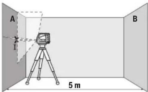
- aasmonn m8gno ysbmmu 30ogmlu A oos anoanlssma bmuuymu 300603gmomnu dusdmo mmbs. am6a60 m8ymo ubn3gonu 800330nnu 366mn (f)
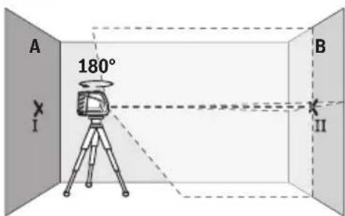
-
amsd6gun 180°-u, uo dojnoa slu 300603cmonngnu 2gludmoedmdu, am6n6gu mssymyn b58jndnu gos330nnu B (gmo II).
-
amsosgun usbman bumusyam - amny6jndu yag - andxboom 30gmmss B, hongn nu gns angnon n3no6nmoanodn agusdmogmbs.
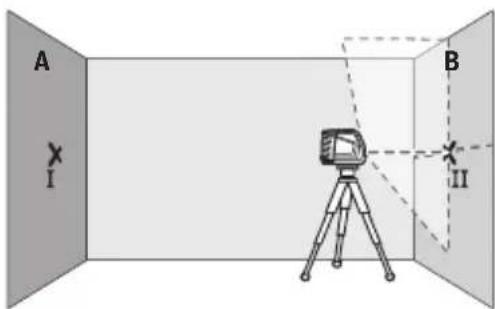
- 856bmngmogwus8man
bnuuysymyu 356nmo
unasmmgnyu, mna (a0s03ol
s6 ufoomndu agab33ad
d3uugdoou ad3gmnon),
m8ymyu ubo30nu aoo330nu
ymynu ylu ynu ndymgdmnu
m8ymyu ubo30nu y6lu
am6ymyu ooo330nu ymgmdn II
3000B.
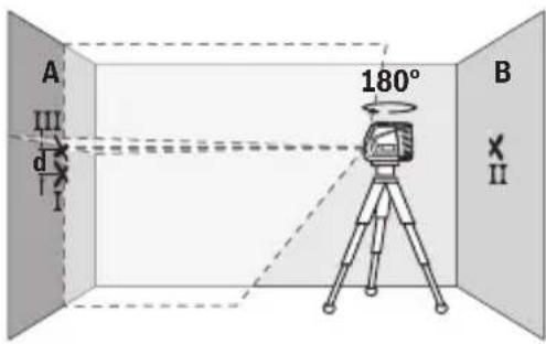
- amsbmy60n 180°-no, 1oasymol o33mou
aog. andsmon 60gmo
300g8A, mda 30gno3ymo
osbnu b8o asoomu 333
dsomoyf yogom 1. dgo
usbma bmyu
o0o6030mojdo
agusdmojdo os am6o
Mgmyn ubo3gndu 800333mou A (Gmnn III).
-ub3smdd 3gog A mnn amnndyym gngomu I os III amnub
Smsa86b1 ssman bumusymyu 3dmoan aossbnlu unoogbu.
sbsmaa m5s33082 2x5a = 10 aadunasymg cosusda3gon asosbm
dsag6b:
10 × ± 0,3 34/8=±34a. s83msu, ubsmds d yomogdu I gss III amnol u 600s oagodgoglu adlu. 3 a-u.
3mno8m5ymyna bssu 5ngjgmjou uoyuogd
aouomgdoomoo aonmogosn m3nogmo ln36gmonnn gssb. 5x5a.
- 0ssd6g jn 1s8m n6u mya A oB 3gymjou ayan oasdmyb 5dsosn3bg, 56 ssy6gm dyam, uomm Lusy3gmyb. Rmonn 1s8man 6lu myo 3omds ynn 6n3gmondo nyasmdunon 0s snhno 3mn8m6gmyn mgnan. gmmnog nn 1s8man n6lu mydgnu 3nno6n3gmongydu.
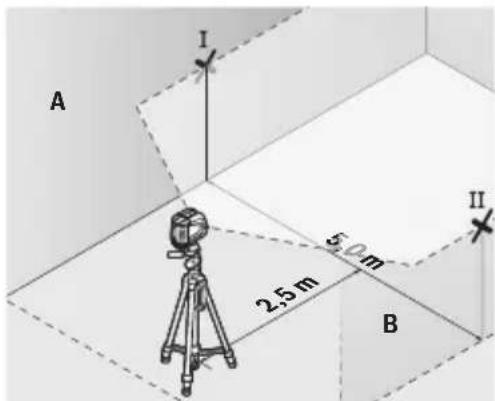
- a60600 m8ymyn b8ydou 350mnn30 30000g2,5 a 4s6dmo8y u8mna 6luoyda60005 (yno I A 30000g y no yno n B 30000g).
292|Jshonmy
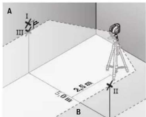
-ossy60n 180°-nn amsmssgmon 5 a 6d0m800s00mmogon 0u 6032mngoslu.
- aessmnnnns nssmn n 650yag6o lnasmmg (aogonol sb gannmngnu 33n nn yag6o) n, ma m8mybnn B66no 8u o qanb33mglu am6nblgnmB
-A 300008g am6n69m m8mynn b8nlu 36mo I15 moomol Lsbnn (36mo36mo8I GmOnm8g 83non 56 33300). - a5dno m n d m6d6y I 0s lll ymoynol amnol A 3oogm8g
aambsu bssman o6uynag5cnu 3mn8m6smolus 3doon
gomangosu.
U8ma a6330082 2x5a=10aundasmygmoosuoad3doaomangds
10 × ± 0,3 3 / = ± 3 3 . 3 3
30000000000000000000000000000000000000000000000000
aamnbnunonu aanmogosom 3mol nmmn, mnaumg 26ds an6ndy 2,5 a onsnyoosnn 3mg (dysm bwo3m8g) 3mol mn03g abmsgl.
-0ssy6g2n 1s8mno n5uymyj6o3mou jmoomoo56 2,5 a 4s6doom8yds m, Ummn uoyd3g8g (sns dgo38g). Hmogon 1s8mno n5uymyj6o3o3moadyn 603mamomomomom ydsmonlun3n. snnn 3m03mymn mgnan gos oogmmgmo n 5s8mn no 5uymyj6o3o3mamomomgdsb.
j60ymo1293
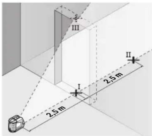
- am6n6603m03mmymo m8mymo bs0nu 050no 3molomnu nss38g (yngnmo I), 4sdo78g 5 a 3molu ngnol agmgo absmg (yngnmo II), sbo30 3moln mo nmbu 8wos absmg (yngnmo III).
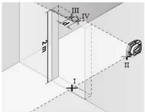
-0ssy62n 1s8man n 6uymy6
3mol momol a mmy abmgl
y6mnmol y356. wogmmg
1s8mdo 6luymy6
m060mgmoosdu yds adsmong
anlu 30m03mmy ms8my
Lb03n oU, md a sno dy
am6330mn gogmogu 8yub
oo II y6mog
- aod6n m8mou 860mol ymo 3mou mombu 8wos 6hmo,
mamgbo mo IV. - ubgsmds dm amn6ygm gomnu I10 IV amnu hmsagbu 58man bmyu 3mogsmnu 6dymmo n 8osbnu unonglu.
-88mgon 3nun nomnu unasymg.
aJundasmyngosuagdo gossbnss
36mol mombol mdasan undsgm × 0,3 a/
aogmon: 3nou mnu lnasmnu gmb 2 a dunssyngs yusd3gon
800006
2×2a×±0,3a/α=±1,2aa.aaamgmoqdoIIIv6
aegsngmoggl 6dngg sns 63gmj0n 1,2 aonssgnb5.
aamg6gonu annnogdo
asmngbnongnuymgmona aamny6gnabmmn m8mynnb8nlu 3056no.m8mynnbsnlu nss6nq3mnsdsdngmo6sadmao66m.
294|Jshonmno
U8n86j 60a6no no ayasmds
Usan862 6nssn (20) sydmojdu m8gmnu ubn3nu bnmsgmdsu
smbusmym 3nmdoo oq qnoq nou66088g.
Usan862 6n6n 6n3m3n 8ws3n (20) syxmdgdu m8mynn b8nu
bnm3scomds, 3n3m3m 8ws3n8g m8mynn bs n 85u Usan862
6n6n y3sbs abmog5.
aOn3nn aysms (sglugusn)
a0030 y6my63ymymou Lusommy, uosmmyb myomnodu Lysmy6bu 1/4" (4)
00000000000000000000000000000000000000000000000000000000000000000000000000000000000000000
usman bumusmyu hmon3sagog n6uun aouuymon ano
2nJusns 6n3mLusmynn oosdymoab d3mmon (sduysma) (ob.uym.F)
y6n3mLusmynn Lssagmoa 03mmon (19) aUsdmoos U8mdn
bomlusymyu osdsngos, asgmoos, 3mO3mmyn bogosmgoj 56
asboynno dsusmolus gosdsgoym 8cos3mgoj. y6n3nuymn
Ussao no jndmgos admy6goj mamms Lwosad. Jusm03gdu
bgmusymylu ndsmgmdo sUvmgdsu.
sduuysmnu 3608608608608608608608608608608608608608608608608608608608608608608608608608608608608608608608608608608
usmnbuusymu hmo3sdog, no5uum 6ubmmgymn yno3msusmymoosdmo 86mngds (19).
mgybmybmylun6 uaydsm uon3oog (sdlguyso)
m8mybmlusymu5 usydm uon3mo gnnmogu asjmu aydu.
snu yysmmn m8ymu dyo n3smolun3nu yom 3sd3ss.
smaamny6mo Iusm3mgon m8myn n6uymo 60nn Iusdysm (sgluysn) osa3n Iusm3mgonu Isbnn. m8mynn n6uymo 60nn Oydsmonlu snaomg on y6mymogm36 m8mynn ubn3nu 32jum d5dngmu, aagnd sn nss36 m8mynn oadmbn3gonu5.
sAsamny6mnsu035mgon m8mynnn 6lu6y6oennusdsm (sugysn) 8ou wosg2n uos3mogndnu 1bmo 56 usglons.
msbmon6 dyasmonu uos3mgon n sm y63ymg36 umn nn-
asdmnbqdoa5 wssu os dyomdu uymn gondnu smjtsu.
usyaasmb aubmygdoabagammonog (nb. ym.F-H)
usmboaumu ymu 3amuy6jduo 3mo56jduo aasmnnoognob. 3336008g omylmsngdo.
6n3ynn amalbsyngos yu3un
036n3mno amalusbmyoos 8666
us8mno bomuluy ymgmo3o lycoos ymb.
sulogbdoomn bsmdbn gmousfym ygmdn 5bbs boombjao.
a#an6ogon fyno monno, 6guosn fumzmonn. sm aadmoy6mon u#j6gon
usaymgdon sasabu6gmdo.
3jmdm,6o8ymofoy 80suygoo33n m8gnnu 8aamul3m
6sb3mogonlu 8gos3nngon mSBgmol 603mnm8g o8my63myo3nn
bsmgonl amyymds.
yBomgmoosg 065bgon os 65bmmboogm usbnn bgmusmy
6n6u3mngnogosgds3gusudan (21).
usman bomusyym 0ss8s36gm agus30mdoos oos33 gnsudan (21).
Gj6n3ynm dmalusbyngdou ulalusbmyn 3m5uym8bnjdoa my6gonu u3noobgdoos6 os3o3dnomdo
0d63mo amalusbmyo luasusbmyo unam36gon 3sbygdu m36u
03nmb3gdu, 36u anm y6ybn gmlusyml/sjubysnab, s239
Lusososomg 6ywnmgonu ygmonosus os gdsn amalubymos
www.bosch-pt.com/serviceaddresses
JOnmno8ouo
usman bumuymgon, duguymgon 0a 30 aosyomg an mduon yusommbn.
s yosymnn 18mna bmygon oos smggon Lysmsbmgom 6m86goos6 gnss!
abmmg 36m33aonnu 3y60nun3u:
33mm33dnnol ngmJg3nL EC 2012/19/EU aJusdsanlu, gadmy6jymn
usbman bumuysymon o 33mm33dnnol nngmJg3nL EC 2006/66/EC
aJusdsanlu, gosns6jymo 56 gadmy6jymo nn 33do
gag6jogon 600s agm3oglu 800s 800s 33mmamng
glssmomb asosdyas3gonlunnl.
Româna
Instruţiuni de siguranta

Service scule electrice
Strada Horia Macelariu Nr. 30-34, sector 1
013937 Bucureşti
www.bosch-pt.com/serviceaddresses
310|BbIrapckn
Eliminarea
JHHeeH na3ep GLL 2-10
Knac Ha 3aunTa IP54 (3aunTa cpeuy npoHnK
BaHe Ha npax HnnpbckBaHe C BOda)
A) Ipn He6naropnraTHn ycnoBna (Ha np. HncpecdTBeHn CbHueBn byn) pa6oTHnT dana30HO MOKe da e nMaJIbK.
B) Ima cmo He npoBOJMO 3aMbpcBaHe, pni KoTo o6aue e Bb3MoXHO da ce ouakBa BpeMeHHO npuHHeHa npoBOJMOCT nopadn KOHe3.
3a eJHO3HaHNOIeHTnOuPHe Ha Baunr H3MepBaTeIeH ypeI cnyKn cepHnrHnrT Homep (10) Ha Ta6ekkata Ha ypeIa.
Mоntиранe
I3non3BaHe/cmHaHa 6aTepuHte
3a 3axpaHbaHe Ha n3MepBaTeHHn ypeI ce npenopbYBa n3NoJ3BaHeTo Ha aNkaJHO-MaHraHOBn 6aTePnn.
3a OTbaprHe Ha KaNaka Ha rHe3dOTo 3a 6atepn (11) HATNCHEte 3actOpraunr ByTOH (12) n cBaIeTe Kanaka. NocTabete 6atepnTe.
BHHMaBaIte 3a npabHnHaTm nolpHocT, n3o6pa3eHa Ha fHpypTa OT BbTpEuHaTa CTpaHa Ha rHe3dOTo 3a 6aTePHN.
Ako HnndnkaTopbT 3a CbctOHHneTo Ha 6atepHnte (7) Mna, To 6atepHnte ca n3toeHN. OTHauanoTo Ha MnraHeTo N3MePBAteHnIypeD MoKe da pa6oTH oSe np6n.1 h.
3aMeHnTe BnHaRn BCnUKN 6aTePNn eNHOBpeMeHNO. N3PON3BaIe BnHaN 6aTePNn OT eINH n CbU pOn3BOdntEn n C eDHaKbB KanaunTeT.
Ako npoDbnKHTeHNO BpeMe HMa Da n3NoI3BaTe HHCTpyMeHTa, n3BaXdaIte 6aTePHTeOT Hero. Pn npoDbnKHTeHNO cbxpaHbAbe H He 6aTePHTe B n3MepBaTeHnHa IHCTpyMeHT MoT Da KopoDnpat N da ce camOpa3peJrT.
Pa6ota c Bbptraata ce stoKa RM 1 (Bx. qnr. A-B)
C nomouTa ha BbptTaaTa ce cToiKa (13) moKeTe da 3aBbptate H3MepBaTeHnHa ypei Ha 360^ . Taka na3eprHnte IHHn Moar Ta da 6bDat no3nOHHpaHn TouHo, 6e3 da 6bde npoMeHnHa No3nIraHa Ha H3MepBaTeHnHa ypei.
IocTaBeTe n3MepBaTeHnY ypeD C B0eUHa KaHa1 (17) Bbpy HnPaBnaBaUaTa
uHa (14) Ha BbptAaTa Ce cToiKa (13) N BKapaTe n3MepBaTeHnY ypeD Do ynp B
PnataopMaTa.
3a demontpnahe n3dbpnaTe n3MepBaTeHnY ypeI OT BbptTaaTa ce cToiKa B npOTBO- noJoxHa nocoka.
Bb3MOXHOCTNaI03NIOHINHpAHeHa BbptTaaTa ce cToiKa:
- NOCTaBeHa Bbpxy paBHa NOBbpxHOcT,
-3aXbHaTa C BnHTObe KbM BePtIkaIIHa IOBbpxHOCT,,
-BKOM6HHaHcBcCKo6aTa3a TaBaHN (18) KbM MeTaHn JaChn Ha TaBaHN, - C NOMOuTa Ha MaHHTHTe (16) KbM MeTaJIH NIOBbpxHOCTN.
Pn3e npbctnte cn OT 3aHaTcTpaHa Ha MaHHTHaTApnHaJNEXHOCT npn 3akpenBaHe Ha NocneHata KbM NOBbpxHOCT. Upe3 CnHaTApnTeRnaCnHa HaMaHHTte npbctnte Bn Moat da ce 3axBaHAT.
Pa6ota
Nyckahe Bekcnoataaia
IpeNa3BaTe H3MepBaTeHHn np6op OT OBnaxHBAHe N DnpeKTHO IonaHa He Na CJIbHcEBN IbU.
He n3naraTe H3MepBaTeHnHa ypeHaekCTpeMHn Tempeatpyn Hn pe3Kn TmepaTyPhn npomeHn. Hanp. He ro octabTte npobJnte Hbme B aBTOMo6n. Pn rOleMn Tempeatpyn KonebaHn octabTte H3MepBaTeHn ypeDa ce aanTnpa Hnpd npobJnaBaHe Ha pa6otata BnHaru H3BbPwBaTe npOBepKa Ha toUHocTTa (Bx. "Piobepka 3a ToHocT Ha n3MePBeTnHa ypeD, CtpaHnca 317). Pn ekCTpeMHn Tempeatpyn Hn rOleMn Tempeatpyn pa3nnKToUHocTtHa n3-MepBaTeHnHa ype Moke Da ce BLOHN.
N368raBte CnHH ydapn Hnn H3nyckaHe Ha N3MepBaTeHnHa ypeD. CneJyapHn Bb3deIcTBn Bbpxu N3MepBaTeHnHa ypeI Tpr6BaJa H3BbpWBeT npOBepKa Ha ToUHOCTTa My, IpeN Da npOdbJnxTe Da ro H3noJ3BaTe (BxK. "PpOBepKa 3a ToUHOCT Ha N3MepBaTeHnHa ypeD", CtpaHnca 317).
Korato npehacate ypea, npeBapntenho ro n3KnIOyBaTe. Pn H3KNIOyBaHe MoDyblT 3a Kone6aTeHN DnIXeHna Ce 3actOpraBa, TbN KaTO npn CnIHn Bn6paun MoKe da 6bJe nobpehen.
BkIOUbaHe n3KIOUbaHe
3a BkIIOUBaHe Ha n3MePbATEHnYpei npemecTe Te NyCKOBn npekbcBau (2)do nO3nTnra"On"(3a pa6ota c maxanHO apetnpaHe) nnDo nO3nTuTa "On"(3a pa6ota c ABToMaTHuHO HnBeHnPaHe). CtaTychaTnHnKaun (7) cbETBa. Behara cneBkIOUBAHe n3MEpBaTeHHrT ypei n3lbUbVa na3epHNnHnNn Ppe3 nXODaHTe OTBOpn (1).
He hacouBaIte na3epHnI Nb4 KbM Xopa HnXHBOTn; He rneJaTe cpeuy na-3epHnI Nb4, cbso n OT rOJMo pa3CToHHe.
316 |Былгарский
3a n3KIOUbaHe Ha n3MePbATEHnY ypeI npemeCTe NyCKOBn IpeKbcBaU (2) B no3n- "Off". CtaTychata HndnKaun (7) yracBa. PpN n3KIOUbaHe MoynbT 3a Kone6aTeHNTE DnXKeHHce 6nOKnpa.
He ocTaBnTe ypeDa BKnUoyen 6e3 Ha3Op; cnei KaTo npKnOuHTe pa6ota, ro n3KnIOuBaIte. Dpyr nnca Moat da 6bDat 3acnenen O T Na3epHnA nbU.
Pn npemnaBaHe Ha MaKcMaHNO dOnyCTMaTa TemnepaTypa ot 50 ^ C ypeBt ce n3KIOUba 3a npedna3BaHe Ha na3epHnI dyo. Cnei oxJaXaHe n3MePbTeHNrT ypeI e OTHOBO rOTOB 3a paOta I MOKe da 6bDe BKIOUeH.
ABTomaTHUHO N3KNIOUbaHe
Ako 3a npn6n.120 MNHytn He 6bJe hATnCHat 6yToH Ha n3MePBATeHNn ypeD, 3a npedna3BaHe Ha 6atepnnte H3MePBATeHNnT ypeD ce n3KnIOuBa aBTOMaTHNo.
3a da BKNIOHTe NOBTOPOHO H3MEpBaTeHnH ypeD CNEd aBTOMaTHUHO H3KIIIOUBAHe, MOKeTe Da N36yTaTe NcCKOBnI ppeKBcBauch (2) NbpBO Ha N03HnCnH "Off" N CneD TOBa OTHOBO Da BKNIOHTe H3MEpBaTeHnH ypeD nH DA HATNCHEt eEHN PbT 6byToaH 3a peXmHa pa-bota c Na3ep (5) nH 6byToHa 3a peXm Ha npneMahe (6).
3aДа DeakTNBnPaTe aBTOMaTHUHOTo N3KlIOUBAHe,HaTNCHe T 3aIpbXTe NOHe 3s6yToHa 3apeKIM Ha pa6Ota (6) (npn BkIIOueH N3MePbATEeH ypeI). PpN DeakTNBnPaHe Ha aBTOMaTHUHOTo N3KlIOUBAHe Na3epHIne IINHH pPmMnBaT KpaTKo 3a NOTBbPjKeHne.
Yka3aHne: Ako pa6oTHata TemnepaTpa HaxBbPnn 45 ^ C , aBTOMaTHUHOTo n3KJIIOuBaHe He MoXe da 6bDe DeakTNBpuHo.
3aДаakTbBnpaTe aBTOMaTHUHOTO n3KJIIOUBAHe, n3KJIIOUeTe n OTHOBo BKIOUeTe n3MepBaTeHHypeI.
Pa6oTHn pexmm
Ia3epHnT ypeI pa3nonara c HЯKoNko pa60THn paBHHN, MeJy KOHTO MoXeTe da npebKIIIOuBaTe NO BcAKO BpeMe:
- peXIM C KpbCTOCAH N IHHN (Bx. fIg. C): rHeepnpa XOpN3OHTaHa N BepTnKaHa Na-3epHa IHHN,
-xopn3oHTaJIeH peKIM (Bxk. qIr. D): reHeepnpa xOpn3oHTaIIHa na3epHa nnHH, - BepTKaJIeH pexm (Bx. qnR. E): reHepnpa BepTKaHa na3epHa nnHna.
CneBkIIOUBaHe H3MepBaTeHnHrT ypeD ce HaMnpa B pexmHa KpbctOo6pa3Ha IHHra.
C6bytoHnTe 3aXopn3oHTaJIeHpeKIM (6)NBePTNKaJIeHpeKIM (5)MOKeTe da BKNIOuBaTe N3KIIIOUBAte He3aBNCMo eHa OTdpyra BePfKaIIHa IOTBeCSHa Na3epHa INHHI.
BcHKnpeKHMnMOrat Da 6bDaT H3NoJ3BaHN KaKTo C aBTOMaTHUHO HNBeHnpaHe, Taka N C maxaHNO apetnpaHe.
ABTOMATNUHO HNBeJInpaHe
Pa60Ta cbc cnCTemata 3a aBTOMaTHUHO HNBENHpAne
IocTaBete n3MepBaTeHnHa ypei Ha xOpH3OHTaJIHa 3dpaBa OCHOBA, 3axBaHete Ro Ha yHn-BepcaHnHa TcOnKa (13) Hn Ha CtaTnB (23).
3a da pa6oTHe c aBTOMaTHUHO HNBENHpaHe, NOCTaBeTe NyCKOBn IpeKbCBauch (2) B no-3nIa " n".
CnCTemata 3a aBTOMaTHUHO HNBENIPAhe KOMNEHCnpa OTKJOHeHnO T XOpN3OHTaNaTbB pAMKInTe Ha dHaIaHa3OHa 3a aBTOMaTHUHO HNBENIPAhe O ± 4^ . HNBENIPAheTo e npNKIOuNo, KOrato Na3epHIne IINHH IpceTaHt Da ce npMeCTBaT.
Ako aBtOMaTHHOTo HnBeJInpaHe He e Bb3MOxHO,HaNP. KOraTO IOBbpxHOCTTa,Ha KOrTo ypeIbTe IocTaBeH, ce OTKIOHOBA OT XOpH3OHTaIaTaNObeue O T 4°, Ia3epHITe IHHN 3a- NOuBaT Da MHRat 6bp30.
B TaKbB Cnyuayn NoCTaBeTe H3MepBaTeHnH ypeD xOpH3OHTaHNO H3UaKaIe aBTOMaTHNHO My HNBENpaHe. Korato H3MepBaTeHnHrT ypeD 6bJe NoCTaBeH B rpaHnIte Ha dHa na30Ha 3a aBTOMaTHUHO HNBENpaHe OT ±4°, Na3ePHnTE NbUn 3aNoUBAr Da CBETr HEnpeKbCHaTO.
Pn pa3bpcBAnHa HIn IpomraHa Na NonoJKeHHeTo NO BpeMe Ha pa6oTa H3MepBaTeHNrYpeI ce HnBeNIPA OTHOBa ABTOMaTHNo. CneI npKIOUbaHe Ha HnBeJIpaHETo npOBePeTe P03uHrTa Ha Ia3epHnTE NbU No OTHoWeHne Ha pepepENTH ToK, 3a Da H36erHe TpeWK BCJeDCTBHe Ha OTMeCTBaHe Ha ypeJa.
DeynoC maxaHApetnpaHe
3a da pa6oTHe c MaxaHNo apetnpaHe, nocTaBeTe NycKOBnI pKeKbCBAu (2) B IIO3nU
Otpa3raBaaata NOBbpxHocT ha Ia3epHaTa MEPntHa IInoya (20) noo6pBa BnIMocT Ta Ha Ia3epHaTa IHHa, a npes Ipo3paHata IOBbpxHOCT Ia3epHaTa IHHN MoKe da Ce BnI N OT o6paTHata CtpaHa Ha Ia3epHaTa MEPntEHa IInoya.
Pa60Ta cbcctaTHB (npHnAdIeXHoCT)
I3noI3BaHeTo Ha cTaTHB OCHpyra Ba cTaNnHO, peryHnpyEmo no BnCOunHa MOHTipaHe Ha I3MepBaTeHNHa ypei. NocTabete H3MepBaTeHNHa ypei c 1/4" NOCTaBKata 3a cTaTHB (4) BBpxy npncbEHHNTeHNHa BHT Ha cTaTHBa (23) nHa o6nKHOBeH TpHNOxHK 3a fOtoanapat. 3a MoHTnpaHeTo KbM cTaHApTeH CTOHApTeH TpHNOxHK N3NoI3BaNTE 5/8" NOCTaBKATA 3a cTaTHB (3). 3aTeHHeTe H3MepBaTeHNHa ypei c BnHTa Ha cTaTHBa.
Ipei Da BkHIOUHTe N3MepBaTeHNnYupei, HacOueTe CTaTHBa rpy6o.
MoHTnpaHe c yHnBepcAnhata cToKa (npHaDnExKHOCT) (BHXTe fHr.F)
C nOMOHTa Ha yHnBepcaHaTa CToKka (19) MoKeTe Da 3axBaIaTe H3MepBaTeHNH ypei HaIp. KbM BepTKaHn NOBbpxHocTn, Tpb6n IINn HamaHrTeH3npaUc Ce MaTePauu. YHnBepCaHaTa CToKka e NODxOJaA CbIo TaKa I 3a NocTaBAre Ha Noda N ObLeKuaBa HactPoIBaHeTO NO BnCOUnHa Ha N3MepBaTeHNH ypeI.
Pn3e Tpbcntte cN OT 3aHaTcTpaHa Ha MarHHTata npHaadLeXHOCT npn 3aKpenBaHe Ha NocneHata KbM NOBbpxHOCTn. Upe3 cnHaT a npnterlaa cna Ha MaHHTTE npbcntte Bm morat da ce 3axBaHaT.
I3paBHeTe yHnBepcaHaTa CToiKa (19) rpy6o, Ipei Da BkIoUHTe N3MePbTeHnna ypei.
OuHa 3a Ha6nOdaBaHe Ha na3epHnaIbU (npHnAdneXHoCT)
OuHnata 3a Na6IIOdaBaHe Ha Ia3epHnI NbU PhInTpnpaT OkOHnHa TcBETnHa. TaKa Ia3epHNATNbU CTaBA No-NeCHO pa3NnHM.
He n3non3BaIte na3epHnTe oUHna (npHHaIeNEXHoCT) KaTo 3auHTn OUYHa. Na-3epHnTe ouHna cnykata 3a no-do6po pa3no3HaBaHe Ha na3epHnHa bU; Te He npednaBbAT OT na3epHO IbueHne.
He n3no3BaIte Ia3epHnte Ounla (npHHaJIeXHOCT) KATO cIbHueBn OUnHa Hn npn WoOphpae. Ia3epHnte OUnHa He npedIarat IIbIHa UV 3aunTa HamaJIaBt Bb3- npneMaHeto Ha UCBetOBete.
Pa60TH HnpHmepn (BnxTe fH)
Iprime 3a npnojKeHneTo Ha n3mePbaTeHHnY ypei MoKte Da Bnnte Ha cTpaHncaTa CfHypnte.
IopdIbpxaHe n cepBn3
PoiDbpxKaHe n nouNCTBaHe
PoiDbpKaIte H3MepeTHe yPeD BnHaHn uHCT.
He nToTnBaTne H3MePBaTeHnH ypeD BbB BOa NII dpyrTeuHocTn.
H36bpcBaTe 3aMbpCraBAHHaTc MeKa,NeKO HaBnaXHeHa KbPna. He H3noI3BaTe no- nCTBaun npenapatn nn pa3TBOpHTeN.
IOnuCTBaItepeIOBHO CneUHNO IOBbPxHOCTHTe Ha I3XoJa Ha Ia3epHnHa IbY HBNMaBaTe Da He OCTaBaT BnACnHKn.
CbxpaHraBaIte n npenacnTe n3MepBateHnY ypeD cMo BbB BKIOueHaTa B OKOMNKeKTOBkata npedna3Ha YaHTa (21).
Ipn Heo6xOIMOCOT peMOHT ppeIOCTaBnTe n3MePbTeHnYupeB VcaHtata (21).
KInnentcKa cnyX6a n KOHCytauHr OTHoCHO ynoTe6ata
CepBn3bT 1e OTROBOpHa Bbnpocite Bn OTHOCHO pEmOHn IIOdpBXKa Ha 3aKyIeHHoT BAc npOdyKT, KaKTo n OTHOCHO pe3epBHN qactn. POKOMnoHENTn YepTeKN INHOpMaunr 3a pe3epBHnTe qactn 1e OTKpneTe n Ha:
www.bosch-pt.com
Ekntno koncuntaa onhocno ynotpebata ha Bosch ue Bn nomorhe c ydoBolctBne npn Bbnpocn 3a nahte npodyktn n TexHnte akcecoapn.
MOna, npn Bbnpocn n npn nopbUbaHe na pe3epBn uactn BnHaHn nocouBaIte 10-ncppeHHa KaTALOKeH HOpE, n3nncaH Ha Tabekata Ha ypeda.
Быларна
Robert Bosch SRL
Service scule electrice
Strada Horia Macelariu Nr. 30-34, sector 1
013937 Bucuresti, Romania
TeN.: +359(0)700 13667 (Блгарский)
ΦaKc: +40 212 331 313
Email: BoschServiceCenterBG@ro.bosch.com
www.bosch-pt.com/bg/bg/
DpyrncepBn3Hn aDpeCh ue oTkphete Ha:
www.bosch-pt.com/serviceaddresses
324 MaKeDoHcKn
БракуВанe
I3MepBaTeHnHrT ype,doBnHrTeHnHrTe npncnoc6neHn H onakOBKnte Tpr6Ba da 6b-dat IopIOxHe H a ekOIOrHuHa npepa6OTka 3a ycBOraBaHe Ha cbDbpKaunTe Ce B Tnx cyPOBHH.
He n3xBbprnTe n3MepBaTeHnTe ypeu H batepHnTe npn 6ntOBnTe OTnaDb- u!
Cama 3a ctpaHn ot EC:
Cbflacno eBponecka dIpekTnBa 2012/19/EC n3MepBaTeHnTe ypeH, KOtO He MoRaTa da ce non3BaT nobuee, a cbflacno eBponecka dIpekTnBa 2006/66/EO noBpeHn nn3xa6eHN o6KnHOBeH nn akymyNaTopHn batePn Tp6Ba Da ce cb6nap t npedaBa 3a OON3OTBOPRAHe Ha cBdbpKaUHTe Ce B TAX CypOBHH.
MaKeDoHcKn
Бe36eHocnHaNoMeHn

CnTe ynatCTBa Tpe6a Da ce npoHTaaT Ha da Ce BHMaba Ha HNB, 3a Da moKe 6e36eHNO H6e3 onaCHOCT Da pa6OTHe co MEPHNOTypeI. Dokonky MEPHnotypeI He ce KopncTH cornacho npnoXeHnte HHCTpyKun, MoKe Da ce HapuHn FyHKunjata Ha BrpaedeHte 3aHTTN MexAHN3MBO MEPHnotypeI.He rH
OwTeTyBaJTe HaneHnUHTe 3a npEynpeyBaIbe. IOBPO CyBAJTE TNOBNE YNATCTBA N PEPADETE TN 3AEHNO COMEPHNOT YPEI.
BHHMaHHe -doKoNky KopnCTHe npyH npedn 3a noDecyBaBe n paKyBaBe oCBeH OBd He HabeDeHnI NonHaKn NoCTaKN, OBA MoKe Da DoBeDe Do onacha H3IOKeHoCt Ha 3paueHe.
MepHnoT ypeI ce nCnpaUyBa co 03HaKa 3a npEynpeDyBaBe 3a Iacepot (O3NaueHO Ha npKAc3OT Ha MEPHnot ypeI ha rpaΦnukTa cTpHa).
Iokonky TeKCTOT Ha 03HaKaTAta 3a npedynpeDyBaHe 3a nacepot He e Ha BaHnot ja3NK, Bp3 Hero 3aneneTe ja HanenHnCata Ha BaHnot ja3NK nped npBata ynoTpe6a.
He ro hacouybajte nacepcknot 3paK KOH Hua HN XHBOTn H HemojTe H Bne camnte Da rnaTe BO dHpekTHnoT Hnn pefneKTnpauchnot nacepckn 3paK. Taka MoKeJa ra 3acJeNTe nnata, da npedn3BnKaTe Heceke Nn da rN OWTte OHTe.
Iokonky nacepcknot 3paKdoCnee do ouHTe,BeHauTpe6a da rN 3aTBOPHTe na ja TprHeTe rnaBata od nacepcknot 3paK.
He npabete npomeHn Ha nacepcknoType.
He rKopnctete nacepcknte 3aHTTHn Ounna (dONOHNTENHa onpema) KaKO 3aHTTHn OUnna. Nacepcknte 3aHTTHn OUnna cnykat 3a noD6po paCno3HaBaHc Ha nacepcknot 3paK; cenak, Tne He wTtAT od nacepckoto 3pauehe.
He rKopnctete nacepcknte 3aHTTHN ouHna (doonHnTeHa onpema) kako ouHna 3a coHcne Hn nak BO COO6paKaJOT. Nacepcknte ouHna He daBaat cenocha UV-3aHTTA n ro HaamanyBaat npeno3HaBaHbeto Ha 6oH.
MepHnot ypeD cMee da ce nonpaba cmo od ctpaHa ha KBaHnФKyBaH ctpyuH nepcoHAn h cmo co opHrHAnHn pe3epBHN deNoBn. CAmO Ha ToJ HauHH Ke 6nnde TcIpyHn BO 6e36eHocTa Ha MEPHnot ypeI.
He rno octabaje deuata da ro kopncat nacepcknot mepeh ype3 ha30p. Be3 Hau3Op, Tne MoKe da ce 3acnenat cebecn nn npyn nua.
He pa6oTeTe co MEPHnOT ypeD BO OKOINHa KaJe NOCTOn ONaCHOCT O ekCnNo3nJa, KaJe HMa 3anAnHB TeuHocTH, rac Hnn npaunHa. MEPHnOT ypeD co3dAbv NcKpN, KOH MoKe Da ja 3anAnat npaBtAn nI npaeata.
He rnpnncybajte MEPHnot ypei n MarheThata onpeMa BO 6n3nHa h mnnaHTn Hn dpyr n MeuHcKn ypei, Ha np. nejcmejkepn Hn HcynHcKa nymna. Ipeky MaHETe Ha MEPHnot ypei n onpemata ce npo3BvBa none, KoeTo MoKe da ja HapuHn cyHKNJata Ha MMnAHTne Hn MeuHcKNe tyepei.
Држete Г Мернот урети Маггета onpema nodaileky od marheTHn Hocayn Ha nodaTOH ypeH n UyBCTBHTENn Ha Marhet. Iopadn BnnaJahneTo Ha mahrteTte OD MEPHNOT upeH n ONpemata MoKe da dojde Do HeNoBpaTHn 3ary6n Ha noDAtoUITE.
Onnc Ha npOn3BODOT n nepOpMaHcnte
BHHMaBaJTe Ha cInKInTe BO ppeHnOt DeI Ha yNaTcBTo 3a KopncTeHe.
Ynotpe6a co cooDbetHa HameHa
MepHnoTypeeHaMeHeT3aOndpeyBaHeI npOBepKa Ha XOpH3oHTaJIHN I BepTKKaJIHN JINHHN.
MepHHoT ypeE e IoroJeH 3a KOpIcTeHe BO BHaTpeSeH N HaIbOpeSeH npocToP.
Inyctpauniha KOMnoHeHTN
HymepnpaheTo Ha cInKte CO KOMnoHeHTn ce odHecyBa Ha npKa3OT Ha MepHnot ypeHa rpaΦnukata CTpaHnca.
(1)ИЗпзэн OTВОР за ЛасярсknOTЗразК
(2)П配电инБачзВКлuyуВаьe/NСКлuyваьe
(3)ПифаТ ha cTaTHBOT 5/8"
(4)ПифаТ ha CTaTNBOT 1/4"
(5) Konque 3a BepTKaJIeH peKIM
(6) Konque 3a xopn3oHTaJIeH peKIM
(7)Прнкзастатус
(8)Приказ осц�ал�орна бнokада
(9)HaTnnc 3a npdeynpdeyBaHbe Ha nacepoT
(10) Cepnck 6poj
(11) Kanak Ha nperpadaata 3a 6atepi
(12)ФнкраHeHaKanakOToNpperpaTa3a6aTeHH
(13) Potaunohen dpxau (RM 1)a
(14)山Ha-BoDnIkaa)
(15) Издожен OTвори за пицврстува。(a)
(16) MarHeT ^a)
(17)BoJeUkxJne6
(18) Cterata 3a noKpB (BM 3)a
(19) YHnBep3aJIeH dpXkau (BM 1)a)
(20)Плесрскацелнатабаa
(21) 3aWHTHa yaHtA
(22)前列腺3aHTTNnOunna
(23) CtaTnB (BT 150)a
(24) Telenckoncka npaupaKa (BT 350)a
a) NnyctpnpaHata Hn OnnHaHa onpema He e JeOn cTaHapHnot 6em Ha Hcnopaka. Lenochata onpema moke da ja hajdete BO haWata Pporpama 3a onpema.
TexHHuKn noDaToCu
| Пиниски ласер GLL 2-10 | |
| Бров на дол | 3 601 K63 L.. |
| Минимално работно поleA) | 10 m |
| Точность на Новелега ве ±0,3 mm/m | |
| Тишино поle на самоньелега ве ±4° | |
| Тишино Вразе на Новелега ве < 4 s | |
| Операимьна Temпература -10°C ... +50°C | |
| Temпература посменения -20°C ... +70°C | |
| Мakс. операимьна Висни пеку решени висни 2000 m | |
| Мakс. релатовна Влажност на Воздунот. 90% | |
| Стосян на Извалкеанocst соред IEC 61010-1 2 | В) |
| Клеса на ласер 2 | |
| Тил на ласер 630-650 nm, < 1 mW | |
| C6 | 1 |
| Остanyва bene 0,5 mrad (целесен arол) | |
| Пробат за статов 1/4"; 5/8" | |
| Батерни 3 × 1,5 V LR6 (AA) | |
| Вразе ласер на р散热имOT на пбotinga | |
| - Ржим на Вкрстени линни 9 h | |
| - Линскри ржим | 17 h |
| Тжига согласно EPTA-Procedure 01:2014 | 0,49 kg |
| Димензни (дожима ×ширина × Висни) | 112 × 55 × 106 mm |
328 MaKeDoHcKn
Плнн检кл晋ср GLL 2-10
BnHa 3aHTTa IP54 (3aHTTa o npaB n
npckahe Boga)
A) Pa6oTHOTo None MoKeJa ce HamaJIIN NopaI IN HeIOBOHn YcNoBn Ha OKOIHHaTa (Ha np. DnpeKTHa H3IOXeHOCT Ha COHueBn 3paI).
B) HactaHyBaat cMoHecnpoBOJINBHeuNCTOTHN, HO NOBpeMeHO ce OuekyBa npHBpeMeHa cnpoBOJNBOCT npeNJ3BkAHa oKoHdeH3aunja.
Cepncknot 6poj (10) Ha cneuHkaHOnHa TIOUka CnyKHa ja Jacha HDeHTNkaJHa BaHnoT Mepeh ypei.
Mонтужа
CtabaBe/MehyBaHe Ha 6aTePm
3a pa6oTa co MepHnOT ypeI ce npenopayBa KOpHCTeHbe Ha aKaNHO-MaHraHcKn 6bATEpHn.
3a da ro OTbOpHTe KanaKOT od nperepaTata 3a 6atepHn (11) npHTncHeTe Ha MexaHn3MOT 3a 3aknyBaHbe (12) n H3BaTe Ro KaNAKOT od nperepaTata 3a 6atepHn. CTabete rH 6atepHnTe.
PnToa BnMaBajTe Ha NIOOBte Cnopei Prka3OT Ha BHaTpeHHaTa CTpaHa oD nperpaIata 3a 6aTePN.
Ako 6atepHnTe ce cna6n, Toraa TpeKka npKa3oT 3a CtaTyc (7).I0 npBOTo TpeKkahe, MepHnot ypeD MoKe Da ce KOpNCTn yuTe oKony 1 h.
Cekora 3aMeHyBaJTe rncnte batepnn oedHa. Kopnctete camo batepnn od eH npOn3BODnten co nct KaNaunTeT.
Ako He ro KopnCTHHe MEPnOT ypeI noDOnIro BpeMe, n3BaTe re 6aTeepnIte.
A B T O M A T H K A T A 3 a H N B E N I P a H e a B T O M A T C K N T H N 3 p a M H y B a H e p a M H N H I T E B O N O I T O H a c a m O H N B E N I P a H e o d ± 4^ . H N B E N I P a H e t o e 3 a B p S h e O T M J I c e P C K H T E L I H H N H e c d b n k a T n o B e k e.
ДOKOLKY He e BO3MOxHOb ABTOMaTcKo HnBelenpaHbe, Ha np. 6nDejKn POnIorata Ha MePHNt ypeD OTCTaNYBa NOBeKe oD 4^ od xOpH3OHTaJIaTа, IacepCKHe 3paun TpenKaat 6p30.
Bo BaKOB cIyuj, noCTaBeTe ro MEPHnot ypeD xOpN3OHTaIIHO nNoueKeajTe ro camOHnBEnHpAbeTo. IToM Ke ce Hajde MEPHnot ypeD BO NoJeTO Ha camOHnBEnHpAbe Od ± 4^ nacepcknte 3paun CBetat HeIpeKnHaTo.
При Вибраци Или помена Ha поожбata 3a Врeme Ha pa6oTa, Мернотуpeд NOВTOPHO ce HNBeInpa aBToMaTcKn. ПО NOBTOPO TO HNBeInpaHbe,пpoBepTe ja NO3njuJaHa NaIacePCKte 3paun BO OdHoc Ha pepepeHTHne TOnKn, 3a Da ce N36erHnat rpeSKITE npn NOMecTyBaHbe.
Pa60Ta co ocunlaTopha 6nokada
3a pa6oTeHbe co ocunlaTopHa 6lokaJa, npTnCHeTe ro npeKHHyBaOTo 3a BklyuYBaHe/ NCKnyUyBaHe (2) BO no3njuJa .On". PpHKa3OT ocunlaTopHa 6lokaJa (8) CBETn CpBeHO I Nacepcknte IHHN HnpeKHHaTO TpeKHaAT Bo 6aBEN TaKT.
Pn pa6oTa co ocunlataopHa 6Ioka a ABToMaTHKaTa 3a HNBEnpaBe e NCKlyueHa.
MepHnot ypeD moKe da ro npKnte cNo6oNHO BO paka nn da ro nocTabte Ha HabaJeHa
noJorA. Iacepcknte 3paun nobKe He ce HNBEnnpaT n He Mopa Da ce BepTKaJIHo
eHa kon dpyra.
KoHTpOHa Ha ToUHocTa Ha MepHnOType
PpIMep: PnBcHnHa HbTbOpOT Ha BpaTaTa 2 m MaKcImaJIHOTo OTCTaNyBaHe CMee Da N3HecyBa
2 × 2m × ± 0,3mm/m = ± 1,2mm . Tóuknite III n IV cmeat da nejat HajMHORY 1,2 mm eHa oD npyra.
Cobetn npa6oteheTo
3a obenexybahe, cekoraw KopncTee ja camo cpeHHata Ha nacepckata nnHna. HnHa ta Ha nacepckata nnHja ce meHyBa co oDaneeyBaBeTo.
Pa6otehe co uehna ta6na 3a nacepot
Lelnata Ta6na 3a nacepot (20) ja nooobpyBa BndnBocTa ha nacepcknoT 3paK npH HeNoBOLHN yCNOBn I rOeMn pactojaHnja.
PeΦneKtpaKaTnOBpHnHa Ha cenHaTa Ta6Na Ha Iacepot (20) ja noDobpyBa BnIINBOcTa Ha IacepckAra HnHa, Hn3 TpaHCnapeHTHaTnOBpHnHa IacepckAra HnHja e BnIINBa nOd 3aHaTc TpaHa Ha cenHaTa Ta6Na Ha Iacepot.
Pa6oTebe co cTaTHB (onpeMa)
CTaTHBOT OBO3MOxUyBa CTA6HnHa MEPHa NODnora ITO MOKe Da Ce NODecyBa NO BNCnHa. NocTabeTo MepHnot ypeD co 1/4"-PnPfAOT Ha CTaTHBOT (4) Ha HABoJOT Ha CTaTHBOT (23) HnObueH fOTo CTaTNB. 3a PnucBpCTyBaHe Ha oBueH rpaedxeH CTaTNB, KopncTeTe 5/8"-Pnpat 3a CTaTNB (3). 3aucBpCTeTo MepHnot ypeD co 3aBPtKa 3a KHKcapaHe Ha CTaTNBOT.
ГрубоцентсягocstatИВOT,прдда roвкльунite Мернnotуpe.
PnucBpcteTe co yHnBep3aen dpxka (onpeMa) (Bnncnka F)
Co nomow Ha yHnBep3aJIHHOT dpxkau (19) MoKe da rO npNcBpCTHTe MEPHNOT ypeHa np. Ha BepTKaJIHH IOBpUHH Hnn MaHHeTn3IpaH N MaTePnJaH. YHnBep3aJIHHOT dpKaH N hCTo Taka IIOJodEH KAKO IODEN CTaTHB IN rO OLeChyBa IIODECyBaHbETo IIO BNCHa Ha MEPHNOT ypeD.
Држete Гпnpстнite подалеку od 3аднот Ден Ha MarHeTHaTo onpeMa Kora ja npnkaaybATE ha NOBpunHnte. Поради jakata сиа Ha Bileye He Ha MaHTe, BaшITE npctn можда ce 3arnaBat.
Ten./daKc:02/2467610
Mo6.:070595888
Д.П.T.Y“POJKA"
JAnu NyKpOBcKn 66;T.LA BToKOMaHaJa loKaI 69
1000 Ckonje
E-nowta: servisrojka@yahoo.com
Bosch Power Tools 1609 92A 7AN| (14.12.2021)
Ten: +389 2 3174-303
Mo6: +389 70 388-520, -530
DOnonHnTeHHaepcnHa cepBnCH MoKe Da HajdeTe npd:
www.bosch-pt.com/serviceaddresses
OtcTpaHyBaBe
Mepnnte ypei, onpemata n ambaanxte Tpeba da ce otctpaHAT Ha ekonouKn npaTnB naHH.
He r n pnpajte mepnnte ypeu n 6aTepnnte Bo domaunata kaHTa 3a f6pe!
Cama 3a 3emjnte oEY:
CnopeEbponckata dnepeKTnBa 2012/19/EU MEPnTe ypei nTo ce BOH ynoTpe6a NdepeKTHnte HnN NcKOpncTeHnTe 6aTePnN CnopeI dnepeKTHBaTa 2006/66/EC mopa OndenHO da ce cobepa Hda ce peuKnnpaat 3a NOBTOpHa ynoTpe6a.
Srpski
www.bosch-pt.com/serviceaddresses
Uklanjanje dubreta
Merni alati, pribor i ambalaža treba da se uključe u reciklažu koja odgovara zašitičovekove okoline.
Merne alate i baterije nemoje bacati u kućni OTPad!
Samo za EU-zemlje:
Prema evropskj direktivi 2012/19/EU merni alati koji se više ne mogu koristiti, a prema evropskj direktivi 2006/66/EC akumulatorske baterije/baterije koje su u kvaru ili astrosene moraju se odvojeno sakupljati i uključiti u reciklažu koja odgovara zašiti Čovekove sredine.
Slovenscina
Varnostna opozorila

www.bosch-pt.com/serviceaddresses
Odlaganje
Merilne naprave, pribor in embalažo oddajte v okolju prijazno recikliranje.
www.bosch-pt.com/serviceaddresses
Zbrinjavanje
Mjerne alate, pribor i ambalažu treba dovesti na ekoloski prihvatljivo recikliranje.
Mjerne alate i baterije ne bacajte u kučni otpad!
Samo za zemlje EU:
Sukladno europskoj Direktivi 2012/19/EU mjerni alati koji vishe nisu uporabivi i sukladno europskoj Direktivi 2006/66/EZ neispravne ili istrosene aku-baterije moraju se odvojeno sakupljati i dovesti na ekoloski prihvatljivo recikliranje.
Eesti
Ohutusnõuded

www.bosch-pt.com/serviceaddresses
Jäätmekäitlus
Lazera skatbrilles (papildiederums)
Lázera skatbrilém piemit ipasiba aizturet apkartéjo gaismu, tapec lázera stars acim liekas spilgtáks.
▶ Nelietojiet lazera skatbrilles (piederums) kā aizsargbrilles. Lāzera skatbrilles in paredzétas lazera stara redzamibas uzlabošanai, tăcu tâs nespej pasargāt acis no lazera starojuma.
▶ Nelietojiet lazera skatbrilles kā saules brilles vai kā brilles, vadot satiksmes lidzekli. Lazera skatbrilles nenodrosina pilnevertigu aizsardzibu no ultravioleta starojuma un pasluktina krasu izskirsanas speju.
Darba operaciju piemeri (atteli F-H)
www.bosch-pt.com/serviceaddresses
www.bosch-pt.com/serviceaddresses
Salinimas
www.bosch-pt.com/serviceaddresses
糜粟
www.bosch-pt.com/serviceaddresses
废弃处理
www.bosch-pt.com/serviceaddresses
廢棄物處理
-ReiJrRnJnJnJnJnJnJnJnJnJnJnJnJnJnJnJnJnJnJnJnJnJnJnJnJnJnJnJnJnJnJnJnJnJnJnJnJnJnJnJnJnJnJnJnJnJnJnJnJnJnJn

; � � � � � � � � � � � � � � � � � � � � � � � � � � � � � � � � � � � � � � � � � � � � � � � � � � � � � � � � � � � � � � � � � � � � � � � � � � � � � � � � � � � � � � � � � � � � � � � � � � � � � � � � � � � � � � � � � � � � � � � � � � � � � � � � � � � � � � � � � � � � � � � � � � � � � � � � � � � � � � � � � � � � � � � � � � � � � � � 5 m 5 m 5 m 5 m 5 m 5 m 5 m 5 m 5 m 5 m 5 m 5 m 5 m 5 m 5 m 5 m 5 m 5 m 5 m 5 m 5 m 5 m 5 m 5 m 5 m 5 m 5 m 5 m 5 m 5 m 100% 100% 100% 100% 100% 100% 100% 100% 100% 100% 100% 100% 100% 100% 100% 100% 100% 1
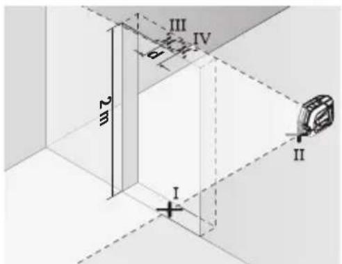
龍龍龍龍龍龍龍龍龍龍龍龍龍龍龍龍龍龍龍龍龍龍龍龍龍龍龍龍龍龍龍龍
尅詠詠公設上,果也。
www.bosch-pt.com/serviceaddresses
封
- 1A uauuua A uuuu uuuu uuuuuuuuuuuuuuuuuuuuuuuuuuuuuuuuuuuuuuuuuuuuuuuuuuuuuuuuuuuuuuuuuuuuuuuuuuuuuuuuuuuuuuuuuuuuuuuuuuuuuuuuuuuuuuuuuuuuuuuuuuuuuuuuuuuuuuuuuuuuuuuuuuuuuuuuuuuuuuuuuUU
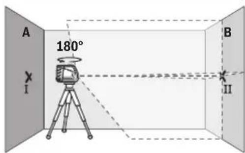
-180° 180°
180°
180°
180°
180°
180°
180°
180°
180°
180°
180°
180°
180°
180°
180°
180°
180°
180°
180°
180°
180°
- 7nnaaannnnn B nnnnnnnnnnnnnnnnnnnnnnnnnnnnnnnnnnnnnnnnnnnnnnnnnnnnnnnnnnnnnnnnnnnnnnnnnnnnnnnnnnnnnnnnnnnnnnnnnnnnnnn
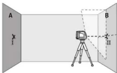
- 777777777777777777777777777777777777777777777777777777
m|473
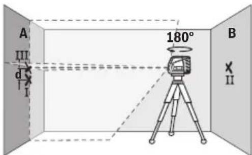
(19)WJU WJU WJU WJU WJU WJU WJU WJU WJU WJU WJU WJU WJU WJU WJU WJU WJU WJU WJU WJU WJU WJU WJU WJU WJU WJU WJU WJU WJU WJU WJU WJU WJU WJU W
Vvuaaunuunnuanauauauunnnnnaaennnnnnae
(19)
Hnnn nnnn nn nnnn nnnn nnnn nnnn nnnn nnnn nnnn nnnn nnnn nnnn nnnn nnnn nnnn nnnn nnnn nnnn nnnn nnnn nnnn nnnn nnnn nnnn nnnn nnnn nnnn nnnn nnnn nnnn nnnn nnnn nnnn nnnn nnnn nnnn nn
lnu ln uun n nn nnnn
Bosch Power Tools 1609 92A 7AN|(14.12.2021)
478
2525 4
10110
tn: +66 2012 8888
wnn: +66 2064 5800
www.bosch.co.th
y
2
10/11 16
www.bosch-pt.com/serviceaddresses
n
1
v 17u
aunssnnnnaannnns
2012/19/EU 2006/66/EC 2007/10/10
Bahasa Indonesia
Laser garis GLL 2-10
| C6 | 1 |
| Divergensi 0,5 mrad (sudut penuh) | |
| Dudukan tripod 1/4"; 5/8" | |
| Baterai 3 × 1,5 V LR6 (AA) | |
| Durasi pengoperasian pada mode pengoperasian | |
| - Mode garis silang 9 h | |
| - Mode garis 17 h | |
| Berat seksuai dengan EPTA-Procedure 01:2014 0,49 kg | |
| Dimensi (panjang × lebar × tinggi) 112 × 55 × 106 mm | |
| Jenis perlindungan IP54 (terlindung dari debu | dan percikan air) |
Palma Tower 10th Floor
Jalan RA Kartini II-S Kaveling 6
Pondok Pinang, Kebayoran Lama
www.bosch-pt.com/serviceaddresses
Caramembuang
www.bosch-pt.com/serviceaddresses
Su thai bo
Dung cu do, phu kien va bao bi phai duoc phan loai de tai che theo huong than thien voi moi truong.
Khong vut dung cu do va pin cung trong rac thai qua gia dinh!
Chi dānh chocac quoc gia thuoc khoi Lien minh Chau Au (EU):
Dung cu do khong con giá tri su dung theo chi thi chau Au 2012/19/EU vac quy/pin bi hong hoac da qua su dung theo chi thi so 2006/66/EC phai duoc thu gom rieng va co the tai su dung theo luat moi truong.
#
JlKl 1sLj

e 100000000000000000000000000000000000000000000000000000000000000000000000000
1 1 1 1 1 1 1 1 1 1 1 1 1 1 1 1 1 1 1 1 1 1
UJw9gI J
()

.(aubabllgwsllaae gwlll 0scg w
gulgglj jllglaag 2
. gaii gl jlllgl aag 1
gglgag ggljgl jllg 1
jUg
gJlI Lc Iqal
4.juUjLgUc
.
joo 2 J jJjU UJU W JUW JUU .jjU E
jIbIs gI juow iUll aLoUly jUll a
.1uJIbIJI Ic bLoU SJlogjglSswuIJI
Lol 1eikosuogigkglaojsswoll osc
JUJI Osc Jusw p "Off, gglg1g1 (2) 1abxI jswll gloo
Jj g (5) wlll Jwll JJ Lc oalg ojo bdo jgl
6
wIaJI Ioc uGsj lo sic) baiI, SuIogjgJl GLoJl aJU Joo
sic. 3 oJol Igdo (6) Jj
oag jgjIbgs aogj, aJloggXl glxI aJlglglo!
.
aJl aJl 45 Jd j 1
.
J 1
山
1g j 2g j 0u Uauu uKs g uu uu 0u uu uu
:g
jg jjL bL qic:(C gall jbl) solll lsswll a
WJ
JolJI IcBgA jI JdJI jn Jn Jn Jn Jn Jn Jn Jn Jn Jn Jn Jn Jn Jn Jn Jn Jn Jn Jn Jn Jn
0sc Jssu. a g uog dui dau jI Lc Igolgol JlJalgl
wull oxc E. g01 l u wll aab jia g gwlil gl go wll
.1gW2I bao gai
-1c jll bcaaio jaiy p9
2,5Lc wlaal oo p
abll) 1Jl lsljll A abaiIg ll Jdll B.(
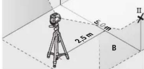
-oo
1JSSa180 5JioI
.ugwulrgogjlg
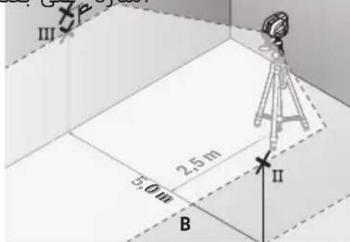
jgI gll lall abwlg) wll oxc IaJgWbI - aJy jll b cnnn nn (ogll sic lao lo wg
B|JxJ|Lc Juaa Jw Jll IabaiI
I aboJU cJg (gg) A JdJI Ic III aboS JJU b a cuaio jauy
.1.sgac
A JdJI Ic nJtalsalll lIg 1uabai j d qjll Jksh
gaggl no wll
:agawalUglaIgluIg10=5x2wUaIagluo
1jibaii jdu gskjuiyjwug .03= /oo 0,3+ x 10
3 1g
gssbll gwll d
Lc(aui aui jui)p2,5uaiyuyiaaiaii
.111 w1g 00 w1 g US
auiu aoujI Lc uUll aad no 2,5 aIwO Uc wUall ooc g
g wll oxc uu u. (pilgall jJ Jolal lc u) agiog
516
oo jI I JU U JU U JU JU JU JU JU JU JU JU JU JU JU JU JU JU JU JU JU JU JU JU JU JU JU JU JU JU JU JU JU JU JU JU JU JU JU JU
-jiulbcbasjua jauy
Uaiai g uIgol
abai)1 5c9 (500 III
Uaiaiai J
abai)IIaJL Uc I
abai)Uaiaiaia
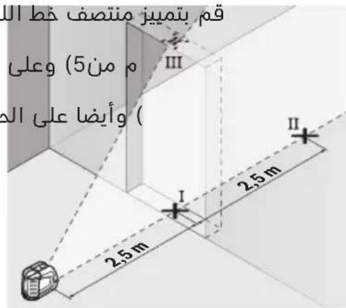
-1JLALIILGwJQILO Ⅳ
a b00g0000000000000000000000000000000000000000000000000000000000000000000000000000
abaii dij lgl aiaa ayaglll adlaI jull baaoo jauo - IV
0 1g 1k 1n jal IV g III n bai I d qal I -
UuI aai 1aJl uuL -
UuLgai Uua 00003xUaI aag ElaJI
gloj 2 2 10 2
Ig III jubai 1j gai d1 00 1,2= p/oo 0,3x 2
.oo 1,2 llo
Jusll Jss
.
jlll nnnnnaa aalg
jjuUgagJgaj)20(jgSj lo sic
.0jS LwJg aoJla jgX
jjU UggluSlaI gBwI pgo)20(baagj aik
I 1111111111111111111111
JJJUUUGaJ aagj
(1gll) glll lalal abwgl
oocg .lgljb u jk aaiu wlg qj gll lal
gai jolal ola i sawly wai1/4 aogy) 4(bgg)
aIgai IJUolal)23.1gWJI
pIgWgWgJgJgSio IwJwOuOgU
101gll Jolal 5/8 aogj)3(
JgJU JUJI UJU
o 1
U
F(ooJ) (g) 10
aIJI Ie wIoll ooc (19) pIJI Jolal pssu y
jolololololololololololololololololololololololololololololololololololololololololololololololololololol
.
C 1
yogol anu jauu u laa oj w sag. gglgll
.1uulbiol
.111 111 111 111 111 111 111 111 111 111
(gIgU) jJUU aGj UJU
jjUg guy uug buaaI gaauogj jll aagj lka
.1uJU lcbw jSjoo
aogj oJbig .aloo jIis (lloJI) JJU1 aqg jUai Jx
.aaabllgwwlllccwllloolssx
518|
aIg aJJI
#
Lulol oxc aolj Lc la lga
Jgll jo 1g lI J g wla o s c ubs
gI cuii 1go pssuW X. aubjg auiw abo abwlg jLwgl wol
.du do slgo
JlI Jll lgl p bio jk wjjg aag sic gbllaa
.
bog aolgl aonl oaiu ly lalg uol oxc jao)21(
aagll aaaa 1g j gj j wlaal osc (Jw)21.
pIaWlUJluuWlgLaJldo
aLxLy,dluggaiJg aIy dalsaiAilwJcdo sa jjo y
jIJIJIJIJIJIJIJIJIJIJIJIJIJIJIJIJIJIJIJIJIJIJIJIJIJIJIJIJIJIJIJIJIJIJIJIJIJIJIJIJIJIJIJIJIJIJIJIJIJIJIJIJIJIJIJIJIJIJIJIJIJIJIJIJIJIJIJIJIJIJIJIJIJIJIJIJIJIJIJIJIJIJIJIJIJIJIJIJIJIJIJIJIJIJIJIJIJIJIJIJIJ
:2g www.bosch-pt.cc
GjA mBoschS JJ U
.lqtaolog liLoo yogosyjluoai
JUJ JIgJgJgJgJgJgJgJgJgJgJg
jLc gbo UuBgI UJluoiW
U
Robert Bosch Morocco SARL
53sgjooaoo jIc
20300LJJ1
:JL+2125293143
:gjJyI sJyI sav.outillage@ma
:ddaaa aaglic no jolll
www.bosch-pt.com/serviceaddresses
aJyKJ 0oJoo
aulll lccababaa aagb ylsllg gglg walssdscn no nalsll
. 11111111111111111111111111
.1J111111111111111111111111
gX1 1gJ b
gjgJdugglw2012/19/EU
gjgJdugglwag JlaaewJdJLJ2006/66/EC
Iqio yalaii piu oLgUs aSglguwll gaiJlJI/psJol
aalai lai jsljol qjubc ailll lcl abaoa
wJ
iJgss

jU jL (J) "On 2" Cgo J L (Jg Jy Jx Jy Jx Jy) "On
()()
.5S Go UJwJ Sjj JsUg j (1) 2g j sIio j i d w jw j I u
p jg g uj k uulg u g lalw d ju ju g
.1gdsoljIgaiSkioljjjglgju laaio
(2) 1/10
· g 7) c2s g jui .jul "Off" Cggo
gaw Go JgJgJy Jdg
Jg g iSj J j j 0
gag juolawl puiu uysu wul jLsol .Laolj gola yjs jI
.
50oC jdo y jLjlo slj g
s jj j j j j j j j j j j j j j j j j j j j j j j j j j j j j j j j j j j j j j j j
.
jLsga b
120 120
.8gawogoljSggbu jyjilcbablaoo gjoljlj
Sjlogil jddgolaj jy g ojl jj l d
JjIg jIg "Off" Coo go Jd IJJ (2) wogal/uggJ dks L dglgo
(5) 15gac sJSLac daS JI Sj Ls i jwogj oJugsj (SjS oJsl
.6)
ojilj1j1 jg jw gj jds) slogilgbj jS Jg
J. J. J. J. J. J. J. J. J. J. J. J. J. J. J. J. J. J. J. J. J. J. J. J. J. J. J. J. J. J. J. J. J. J. J. J. J. J. J. J. J. J. J. J. J. J. J. J. J. J. J.
SauogS,ul jjI bgs,glgil gag jgge
.
gjglj jgjlj45°CjlSlslosdsjjgssd:di
.3J Uloa JUlogil
526|wJ
oJg g oJgol j 5uS oJdjljI ,logil bag Jogai Jg .siS uWg
JSLac gjl
jUloj uIgJ GdSduu JSLAC ggi juiy slg oJsi JjI 1sJusJJ Ugj gJ SfLl Jy LdsLac u
-1gai dui S Ego
gwhoulgj
-1gai duiS eg
-ugaiuS
g jg bao gbsjSla oJdil jIb, nJrsk wg jI Ws
ba jlg (5) 5gac sJSLAC g (6) 1sJSLAC sldaS y. J
. 1wgoa g jw g Jaauwo jgb I ydsagc g 1j
Uaui Ugdy Jgogg Lgogil jy npn lgq Go I wSslac po
.
logjI
sIlogJIJJJJ
0uJusj s9jI jI,du Jg JgJgJgJgJgJgJgJgJgJgJgJgJgJgJgJgJgJgJgJgJgJgJgJgJgJgJgJgJgJgJgJgJgJgJgJgJgJgJgJgJgJgJgJgJgJgJgJgJgJgJg
On 2) 10g g bds k, sIlogil jj lks c 4o JSGJgwhj oogd JlloJgai Ij j SiiS i j jbgs d jio .sio pui ylogil g
oJi jIjI gBw JUa y, wu y u kol sIgil jui 40 ju 5u .ij Go Saw
jw jIg g Jg 1g jg b u I y s oJsi JjU U g u Jy S OJsi JIg dsi U a .u k u Sgwh jj Dg u G u G u G u G u G u G u G u G u G u G u G u G u G u G u G u G u G u G u G u G u G u G u G u G u G u G u G u G u G u G u G u G u G u G u G u G u G u G u G u G u G u G u G u G u G u G u G u G u G u G u
$$ m = 1 0 \text {的} $$
JUULI lgl aai j d 10 m x ± 0,3 mm/m = ± 3 mm
$$ \mathrm {c u l g i 3 . s w l j i o u l o} $$
gac bajj jus
.1JwJ (21) 1000 J J J J J J J J J J J
juiuwo ly oJgluoglo
Iabg g uugw, jooj J laow 21g w d, sjuu lo
LbBgBgJooIcIbI gSsduwIgauai .sIuolgsewy
:uuu ujj laijli jS u
www.bosch-pt.com
jUjJoo oJgLoo ogS BoschoJUJ Lw
. sin s o e w y lalao g Xgaa
i jlaa l aai k 10
L
U
wJUJJWg-|g
yliqj yu, yol s uqw jyuaSig jldso
oJaw, jy yj kau3
1994834571
:42039000+ 9821
:duaolsljJlJlJdJwJd
www.bosch-pt.com/serviceaddresses
oLswJdSgJl
