BC 4535 IIS Premium - Grass trimmer AL-KO - Free user manual and instructions
Find the device manual for free BC 4535 IIS Premium AL-KO in PDF.

| Product type | Brushcutter |
| Brand | AL-KO |
| Model | BC 4535 IIS Premium |
| Engine type | 2-stroke, air-cooled |
| Displacement | 42,7 cm³ |
| Power | 1,1 kW |
| Dry weight | 7,6 kg |
| Operating weight (without fuel) | 9,0 kg |
| Fuel tank capacity | 1,1 l |
| Ignition | Electronic |
| Spark plug | L8RTC |
| Drive | Centrifugal clutch |
| Handle | Bike handle |
| Guaranteed sound power level | 113 dB |
| Sound pressure level | 102 dB |
| Vibration (hand-arm) | ≤ 15 m/s² (uncertainty K = 2,25 m/s²) |
| Cutting line diameter | 2,5 mm |
| Cutting width (line) | 41 cm |
| Cutting width (blade) | 25 cm |
| Maximum engine speed | 9 500 tr/min |
| Idle engine speed | 2 800 ± 150 tr/min |
| Cutting tool speed | 7 500 tr/min |
| Included accessories | Blade (ref. 112405), line head (ref. 112406), shoulder strap (ref. 411705) |
| Fuel mixture | 50:1 (gasoline/2-stroke oil) |
| Spark plug electrode gap | 0,635 mm |
Frequently Asked Questions - BC 4535 IIS Premium AL-KO
User questions about BC 4535 IIS Premium AL-KO
0 question about this device. Answer the ones you know or ask your own.
Ask a new question about this device
Download the instructions for your Grass trimmer in PDF format for free! Find your manual BC 4535 IIS Premium - AL-KO and take your electronic device back in hand. On this page are published all the documents necessary for the use of your device. BC 4535 IIS Premium by AL-KO.
USER MANUAL BC 4535 IIS Premium AL-KO
natural_image
Technical line drawing of a mechanical lever device with two articulated arms and a handle (no text or symbols)| D | DK |
| GB | S |
| NL | N |
| F | FIN |
| E | EST |
| P | LT |
| I | LV |
| SLO | RO |
| HR | BG |
| SRB | RUS |
| PL | UA |
| CZ | GR |
| SK | MK |
| H | TR |
INFORMATION | MANUALS | SERVICE
AL-KO Motorsensen BC 4535 II-S
Betriebsanleitung


D ... 6
EN 15
NL 24
FR 33
ES 42
PT 51
IT 60
SL 69
HR 77
SR 86
PL 95
CS 104
SK 113
HU 122
DA 131
SV 139
NO 147
FI 155
ET 164
LT 172
LV 181
RO 190
BG 199
RU 209
UK 219
EL 229
MK 239
TR 249
3
4
6
8
Antonio De Filippo Managing Director
Safety instructions....16
Assembly....17
Fuel and Operating fluids....18
Startup....18
Operation....19
Maintenance and care.... 20
Storage....21
Recommissioning.... 21
Disposal....21
Troubleshooting....21
EC declaration of conformity....22
Warranty....23
ABOUT THIS HANDBOOK
Read this documentation before starting up the machine. This is a precondition for safe working and flawless operation.
- Observe the safety warnings in this documentation and on the product.
This documentation is a permanent integral part of the product described and must be passed on to the new owner if the product is sold.
Explanation of symbols

CAUTION!
Following these safety warnings carefully can prevent personal injury and/or material damage.

Special instructions for greater ease of understanding and improved handling.
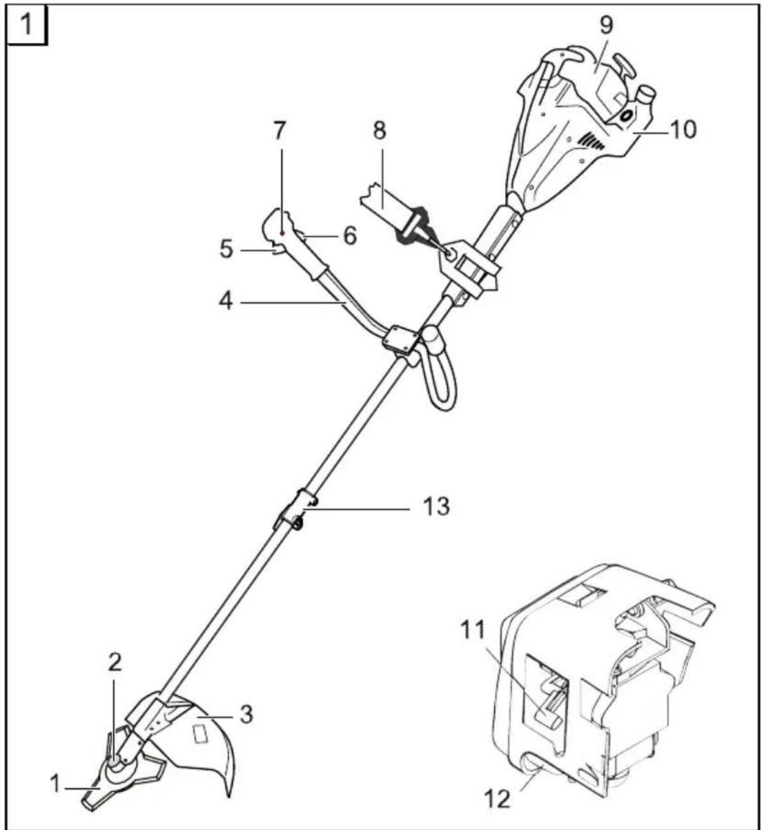
PRODUCT DESCRIPTION
This documentation describes a hand-held scythe with a petrol engine.
Product overview
see Figure 1
| 1 | Cutting blade |
| 2 | String head |
| 3 | Guard |
| 4 | “Bike” grip |
| 5 | Gas lever |
| 6 | Engine ON / OFF switch |
| 7 | Gas lever lock |
| 8 | Shoulder strap |
| 9 | Air filter shroud |
| 10 | Petrol tank |
| 11 | lever “Choke / Run” |
| 12 | Primer (cold-start) |
| 13 | peel-away sheath |
Symbols on the machine

Caution! Special care required during use.

Read the operating instructions before start-up.

Wear safety goggles, safety helmet, ear defenders.

Wear gloves.

Wear safety shoes.

Keep body and clothing away from cutting parts.

Danger due to ejected objects!

The distance between the device and other persons must be at least 15 m.
Safety and protective equipment
Emergency Stop
In the event of an emergency, swith the ignition switch to "STOP".
Stone impact guard
Protects the operator from ejected objects. The integrated cutter shortens the cutting string to the permissible length.

CAUTION!
Risk of injury!
Safety and protective devices should not be disabled.
Split shaft
Via the split shaft, you can easily assemble the Motorsense, take it apart after mowing and store compactly.
TECHNICAL DATA
BC 4535 II
| Motor type 2-stroke, air-cooled | |
| Cylinder capacity 42,7 cm3 | |
| Power: 1,1 kW | |
| Dry weight 7,6 kg | |
| Operating weight without petrol | 9,0 kg |
| Fuel capacity 1,1 l | |
| Ignition Electronic | |
| Spark plug L8RTC | |
| Drive train Centrifugal clutch | |
| Grip „Bike“-grip | |
| Sound power level 113 dB ± LpA 3 bdB | |
| Sound pressure level | 102 dB |
| Vibration | ≤ 15 m/s2 uncertaintyK 2,25 m/s2 |
| String diameter | 2,5 mm |
| Cutting width, string | 41 cm |
| Cutting width, cutting blade | 25 cm |
| Max. engine speed | 9.500 U/min |
| Engine idle speed | 2800 ± 150 U/min |
| Tool speed | 7.500 U/min |
■ Use the machine only in perfect working order.
- Do not deactivate safety and protection devices
The machine must not be operated with different cutting tools or attachments.
■ Wear appropriate working clothes:
■ Long trousers, sturdy footwear, gloves.
■ Safety helmet, safety goggles, ear defenders.
■ Always ensure stability when working.
The machine must not be operated if the operator is under the influence of alcohol, drugs or medication.
■ Always operate the appliance with two hands.
- Keep the handles dry and clean.
- Keep body and clothing away from cutting parts.
- Keep others away from dangerous areas.
■ Remove foreign objects from the working area.
■ Always keep the guard, string head and engine free of mowing debris.
Before leaving the equipment unattended:
Turn the engine off
- Wait for the cutting unit to stop
Do not leave the appliance unsupervised.
Children and other persons who are unfamiliar with the operating instructions must not operate the machine
Before use, check that all screws, bolts and nuts on the device are tight.
Insert the blade guard for ever, before they transport the device or the knife or store.
ASSEMBLY

CAUTION!
The machine must not be put in operation before it has been assembled completely.
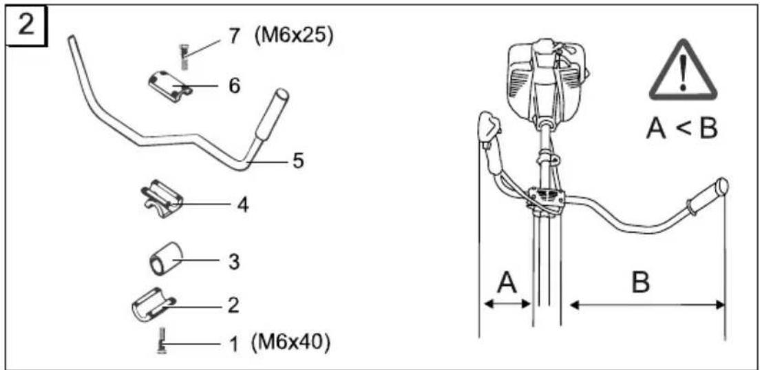
Mounting the "Bike" grip
see Figure 2
- Place the rubber sleeve (3) over the shaft.
- Fasten the lower brace (2) and the center piece (4) using the four Allen screws (1).
- Place the grip rod (5) into the grip holder and fasten with the upper brace (6) and the four Allen screws (7).
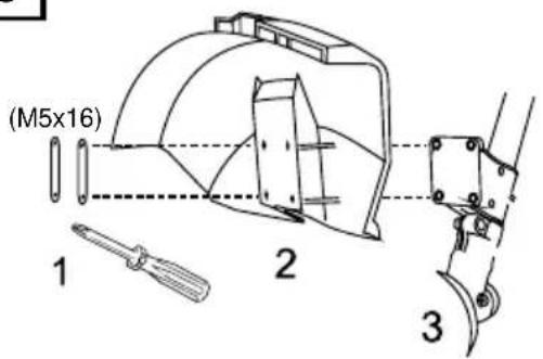
Mounting the guard
see Figure 3
- Place the metal plate (2) under the guard (3).
- Fasten to the support bar with 4 screws (1).

The cutter integrated into the guard automatically shortens the cutting string to the optimal length.
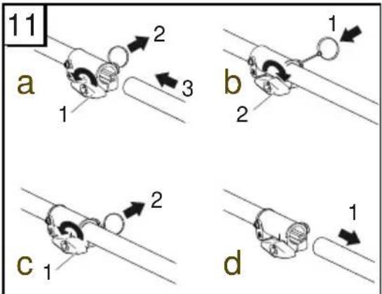
Mounting the rail
see fig. 14
- Slide the lower half of the rail into the holder.
- Engage the button.
- Tighten the holder.
Mounting the rail
see fig. 11
-
Release the lock nut (a -1) and pull out the splint (a -2) slightly.
-
Insert the lower rail with the protective cover (a -3) in the upper rail.
→ Insert guide groove on the splint side.
- Release the splint again (b -1) and secure the lower rail with the lock nut (b -2).
Detaching the rail
see fig. 11
- Release the lock nut (c -1) and pull out the splint (c -2) slightly.
- Pull the lower rail with the protective cover (d -1) out of the upper rail.
→ The Motorsense is now more compact for storage.
Mounting the cutting blade
see Figure 4
- Remove the smaller half shield from the guard.
- Remove the cotter pin (8) and flange (5).
- Place the cutting blade (4) on the drive plate (2) in such a way that the hole in the cutting blade is exactly aligned with the guide circle of the drive plate.
- Push the flange (5) onto the cutting blade so that the flat side faces the cutting blade.
- Secure the clamping nut (7) on the guide pin (1). To do this, insert the Allen key (3) into the hole provided and tighten.
→ Caution: left-hand thread!
- Secure the nut with the cotter pin.
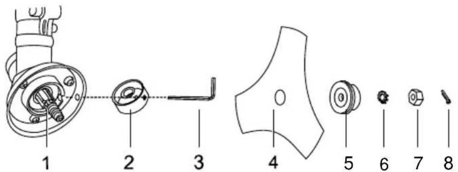
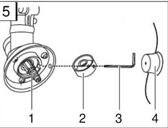
Mounting the string head
see Figure 5
- Remove the cotter pin and flange.
- Insert an Allen key (3) into the hole in the drive plate (2) and screw the string head (4) onto the guide pin of the drive shaft (1).
→ Caution: left-hand thread!
- Lock the drive plate with the Allen key in order to mount the string head.
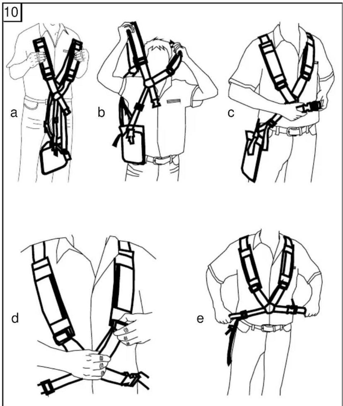
Adjusting the shoulder strap
see Figure 10
- Push the shoulder strap first over the left shoulder.
- Hook the locking hooks into the eyelet.
- Check the length of the shoulder strap by making a number of swinging movements without switching on the engine.
The string head or cutting blade must move parallel to the ground.

CAUTION!
Always use the shoulder strap when working with the device. Only hook up the shoulder strap once the engine is started and idling.
Fire danger! Petrol is highly flammable!
■ Store petrol in designated containers only.
■ Only refuel in open air.
■ Never smoke while refilling!
Do not open the tank cap while the engine is running or if the machine is hot.
- Replace a damaged petrol tank and/or tank cap.
■ Always close the tank cap.
If petrol has been spilt:
Do not start the engine
Do not start the equipment
Clean the equipment

WARNING!
Never leave an engine running in an enclosed space. Toxic hazard!
Preparing a fuel mixture

Only use fuel in a ratio of 50:1.
- Pour petrol and a branded 2-stroke oil into a suitable container in accordance with the table.
- Mix both parts thoroughly.
Table of fuel mixing ratios
Mixing procedure Petrol Mixing oil
| 50 parts petrol:1part mixing oil2-stroke mixing oil | 1 l 20 ml | |
| 3 l 60 ml | ||
| 5 l 100 ml |
STARTUP

CAUTION!
Always perform a visual check prior to start-up.
The device may not be used if there are any loose, damaged or worn out mounting parts or if the cutting unit is loose, damaged or worn out.
■ Always operate the trimmer with the guard.
■ Always observe the operating instructions supplied by the engine manufacturer.
- Check the cutting parts for damage or cracks before use, and exchange any damaged or worn parts for original spare parts.
Starting the engine

WARNING!
Never leave an engine running in an enclosed space. Toxic hazard!
Before start-up, shorten the cutting string to 13 cm to avoid overloading the engine.
- Observe local ordinances regarding operating times.
Choke settings
| |↘| | |↓| |
| CHOKE | RUN |
Kaltstart

CAUTION!
Risk of kickback!
Always pull the starter cord straight out. Do not let it snap back too quickly.
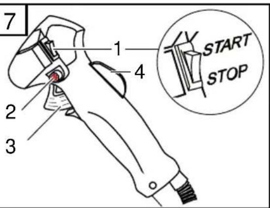
see Figure 7
- Set the ignition switch to the "Start" position.
- Lock the gas lever.
a) Press the "Lock off" switch (2) inwards. Then simultaneously press the gas lever (3) and the gas lever lock (4).
b) Release the "Lock off" switch. The gas lever latches into full throttle.
see Figure 6
- Set the choke (1) to the "CHOKE" position.
- Squeeze the fuel pump (2) 10 times.
-
Pull the starter cord out straight 3-4 times until the engine starts (turns on) quickly and audibly.
-
Once the engine has started: set the choke to "RUN".
- Pull out the starter cord until the engine starts.
- If the engine fails to start, please repeat steps 1-7.
Warm start
- ZSet the ignition switch to "Start".
- Set the choke to "RUN".
- Lock the gas lever as described under "Cold start".
- Pull the starter cord a maximum of 6 times. → the engine starts.
- Keep the gas lever pressed down until the engine runs smoothly.
Engine does not start
- Set the choke to the "RUN" position.
- Pull the starter cord 5 times.
If the engine still does not start
- Wait 5 minutes and then try again with the gas lever pressed down.
OPERATION
Always let the engine run in the upper speed range during trimming and cutting.
Safety instructions

CAUTION!
Please observe the safety and warning notices in this manual and on the product.

CAUTION!
During extended periods of use the vibrations can cause disorders of the blood vessels or nervous systems of the fingers, hands and wrists. You may experience parts of your body going numb, twinges, pains or changes in the skin. If such symptoms arise, please consult your doctor!
■ Never hold the string head higher than knee level when the device is in operation.
■ Never work on a slippery hillside or slope.
When mowing on sloping ground, always stand downhill of the cutting device.
- Never use the device in the vicinity of highly flammable liquids or gases – Risk of fire and/or explosion!
■ After contact with a foreign object:
■ Switch off the engine.
Examine the device for damage.
Persons who are not familiar with the trim-mer should practise handling it with the engine switched off.
Avoiding recoil

CAUTION!
Risk of injury from uncontrolled kick-back!
Do not use cutting blade near solid obstacles.
Dense vegetation, young trees or brushwood can jam the cutting blade and stop it turning.
- Avoid jamming by noting the direction in which the vegetation leans and then cutting from the opposite side.
If the cutting blade becomes entangled during cutting:
■ Switch off the engine immediately.
Hold up the device so that the cutting blade does not jump or break.
■ Push the caught material away.
Trimming
- Examine the terrain and determine the desired cutting height.
- Guide and hold the string head at the desired height.
- Swing the device from side to side in a sweeping, scythe-like motion.
- Always keep the string head parallel with the ground.
Close trimming
- Hold the device so that it is tilted forward at a slight angle and moves just above the ground.
- Always trim away from your body.
Trimming along fences and foundations

CAUTION!
Risk of injury from uncontrolled kick-back!
Do not use cutting blade near solid obstacles.
- Move the device slowly and with care, ensuring that the string does not impact with obstacles.
Trimming around tree trunks
- Guide the device slowly and carefully around tree trunks, ensuring that the cutting string does not touch the tree bark.
- Mow from left to right around tree trunks.
- Cut grass and weeds with the tip of the string and keep the string head tilted slightly forwards.

Trimming along stone walls, foundations and tree leads to increased string wear.
Mowing
-
Tilt the string head to the right at an angle of 30 degrees.
-
Move the handgrip to the desired position.

CAUTION!
Risk of injury / damage to property from ejected foreignobjects!
Remove foreign objects from the working area.
Mowing with the cutting blade
When mowing with the cutting blade, the cutting blade should be guided in a curving horizontal motion from one side to the other.
Before using the cutting blade, observe the following additional instructions:
Use the shoulder strap.
- Check that the cutting blade is correctly fitted.
■ Wear protective clothing and eye protection.
Do not use weed cutter blades for cutting brushwood and young trees.

CAUTION!
Only use original cutting knives and accessories! Non-original parts can cause injuries and device malfunctions!
Switch off the engine
-
Release the gas lever and let the engine idle.
-
Set the ignition switch to "STOP".

CAUTION!
Risk of injury!
The engine continues to run after it is switched off.
Lengthening the cutting string
- Let the engine run at full throttle and tap the string head on the ground.
→ The string is lengthened automatically.

The cutter on the guard shortens the string to the permissible length.
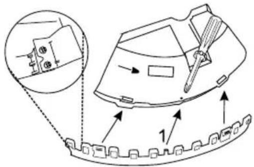
Cleaning the guard
- Switch off the device.
- Carefully remove mowing debris with a screw-driver or similar tool

Clean the guard regularly to prevent the shaft tube from overheating.
MAINTENANCE AND CARE
Air filter

CAUTION!
Never operate the device without an air filter. Clean the air filter regularly. Exchange the filter if damaged.
- Remove the star screw, take off the cover and take out the air filter.
- Clean the air filter with soap and water. Do not use petrol!
- Allow the air filter to dry..
- Install the air filter in reverse sequence.
Fuel filter

CAUTION!
Never operate the device without a fuel filter. Severe engine damage may result.
- Completely remove the fuel cap.
- Empty the remaining fuel into a suitable container.
- Pull the filter out of the tank with a wire hook.
- Remove the filter with a twisting motion.
- Exchange the filter.
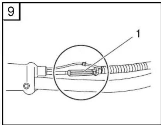
Adjusting the Bowden cables
see Figure 9
The Bowden cables of your strimmer are factory-adjusted. If the position of the “bike grip” handle is significantly changed, this can cause the Bowden cable to stretch, resulting in malfunctioning of the throttle.
If the cutting head does not come to a standstill after the strimmer has been started and the half
throttle lock has been released, the Bowden cable must be adjusted by means of the adjusting screw (1). Correct functioning of the throttle is then assured once again.

CAUTION!
Risk of injury from rotatingcutting head!
Only adjust Bowden cables with the engine switched off.
■ Only check the function with the strimmer lying down.
Sharpening the string cutter blade
- Remove the cutting blade from the guard.
- Clamp the cutting blade in a vice and sharpen it with a flat file.
File in one direction only!
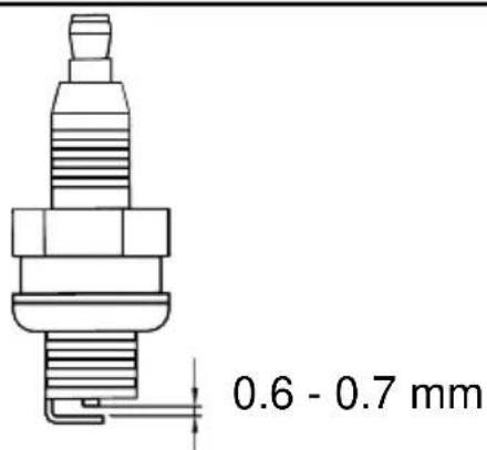
Spark plug
- Tighten the spark plug with a torque of 12-15 Nm.
- Push the spark plug connector onto the spark plug.

Spark plug gap = 0,635 mm [0.025"]. see Figure 8
Carburettor adjustment
The carburettor is optimally adjusted at the factory.
STORAGE

CAUTION!
Risk of fire and/or explosion!
Do not store the machine in the vicinity of naked flames or heat sources.
■ Empty the fuel tank before long periods of storage (over the winter).
TROUBLESHOOTING
■ Only empty the fuel tank outdoors.
- Allow the engine to cool down before storage.
Steps
- Empty the fuel tank.
- Start the engine and let it idle until it stops.
- Let the engine cool down.
- Loosen the spark plug with a spark plug socket.
- Pour a teaspoon of 2-stroke oil into the combustion chamber.
- Pull the starter cord slowly several times to distribute the oil in the interior of the engine.
- Insert the spark plug again.
- Thoroughly clean and service the device.
- Store the device in a cool dry place.

CAUTION!
Fire hazard!
Do not store fuelled machine in buildings where the petrol fumes might come into contact with naked flames or sparks!
RECOMMISSIONING
- Remove the spark plug.
- Quickly pull the starter cord to remove leftover oil from the combustion chamber.
- Clean the spark plug and check the spark gap. Replace if necessary.
- Prepare the device for operation.
- Fill the tank with the correct fuel/oil mixture.
DISPOSAL

Do not dispose of old equipment, batteries or accumulators as householdwaste!
Product, packaging, and accessories were made with recyclable materials, and should be disposed of accordingly.
PROBLEM POSSIBLE CAUSE CORRECTION
Engine does not start Incorrect starting procedure Observe operating instructions
| Engine starts but does not continue to run | Wrong lever position on the choke | Set the lever to RUN |
| Dirty, incorrectly adjusted or wrong spark plug | Clean, adjust or exchange the spark plug |
PROBLEM POSSIBLE CAUSE CORRECTION
| Fuel filter clogged Exchange the filter | ||
| with full performance | Wrong lever position on the choke | Set the lever to RUNEngine starts but does |
| Air filter clogged Clean or exchange the filter | ||
| Motor runs spasmodically Dirty, incorrectly adjusted or wrong spark plug | Clean, adjust or exchange the spark plug | |
| Excessive smoke Incorrect fuel mixture Use the correct fuel mixture | ||

In the case of faults that are not listed in this table, or faults that you cannot rectify without assistance, please contact our customer service department.
EC DECLARATION OF CONFORMITY
We hereby declare that this product in the form in which it is marketed by us complies with requirements of the harmonized EC directives, EC safety standards and the product-specific standards.
Product Manufacturer Authorised representative
Serial number EC Directives Harmonised standards
| G 230 2305 2006/42/EC | ISO 11806:2009-01 | |
| 2004/108/EG | ISO 14982:1998-09 | |
| Kötz, 6 June, 2012 | 2000/14/EG (13) | |
| 2002/88/EG |

Antonio De Filippo
Managing Director
Sound power level
measured: 109 dB(A)
guaranteed: 113 dB(A)
Conformity assessment
2000 /14/EC Appendix V
WARRANTY
If any material or manufacturing defects are found during the statutory customer protection period, we will either repair or replace the equipment, whichever we consider the more appropriate. This statutory period may vary according to the legislation in force in the country where the equipment was purchased.
Our warranty is valid only if:
The equipment has been used properly
The operating instructions have been followed
Genuine replacement parts have been used
The warranty is no longer valid if:
The equipment has been tampered with
■ Technical modifications have been made
The equipment was not used for its intended purpose
The following are not covered by warranty:
■ Paint damage due to normal wear
■ Wear parts identified by a border [xxx xxx (x)] on the spare parts list
Combustion motors (these are covered by a separate warranty from the manufacturer concerned)
The warranty period begins on the purchase by the first end user. Decisive is the date on the receipt. To make a claim under warranty, please take this statement of warranty and proof of purchase to the nearest authorised customer service centre. This warranty does not affect the usual statutory rights of the customer relative to the seller.
ORIGINELE GEBRUIKERSHANDLEIDING
Inhoudsopgave
Over dit handboek....24
Antonio De Filippo Managing Director
Geluidsniveau
INFORMATIONS SUR CE MANUEL
DÉCLARATION DE CONFORMITÉ CE
Antonio De Filippo Managing Director
Antonio De Filippo Managing Director
Antonio De Filippo Managing Director
Nível de ruído
Antonio De Filippo Managing Director
PROBLEM MOŽEN VZROK POPRAVA
PROBLEM MOŽEN VZROK POPRAVA
Antonio De Filippo Managing Director
Raven zvočne moči
Antonio De Filippo Managing Director
Razina zvučne snage
| izmjerena: 109 dB(A) | 2000 /14/EG Prilog V |
| zajamčena: 113 dB(A) |
JAMSTVO
Eventualne pogreške u materijalu ili izradi uređaja uklonit ćemo unutar zakonskog roka zastare za podnošenje zahtjeva za uklanjanjem nedostataka po našem izboru u vidu popravka ili u vidu isporuke zamjenskog uređaja. Rok zastare ovisi o zakonima zemlje u kojoj je uređaj kupljen.
Antonio De Filippo Managing Director
USTERKI I ICH USUWANIE
Antonio De Filippo Managing Director
Poziom mocy dźwięku
Antonio De Filippo Managing Director
Směrnice EU
2006/42/EG
2004/108/EG
2000/14/EG (13)
2002/88/EG
Antonio De Filippo Managing Director
Smernice EÚ
| 2006/42/EG |
| 2004/108/EG |
| 2000/14/EG (13) |
| 2002/88/EG |
Hlučnost'
| nameraná: 109 dB(A) |
| zaručená: 113 dB(A) |
Harmonizované normy
| ISO 11806:2009-01 |
| ISO 14982:1998-09 |
Vyhodnotenie zhody
Antonio De Filippo Managing Director
Zajnyomásszint
Antonio De Filippo Managing Director
Lydeffektniveau
| målt: 109 dB(A) |
| garanteret: 113 dB(A) |
Overensstemmelsesvurdering
| 2000 /14/EG bilag V |
GARANTI
Antonio De Filippo Managing Director
Ljudeffektnivå
Tabell for blandingsforhold for drivstoff
| Blandingsprosess Bensin Blanding-solje | ||
| 50 deler bensin:1 del blandingsolje2-takts blandingsolje | 1 l 20 ml | |
| 3 l 60 ml | ||
| 5 l 100 ml | ||
IGANGKJ∅RING

OBS!
VEDLIKEHOLD OG PLEIE
Luftfilter

OBS!
Stille inn forgasser
Antonio De Filippo Managing Director
Lydtrykknivå
målt: 109 dB(A) garantert: 113 dB(A)
Samsvarserklæring
2000 /14/EG tillegg V
GARANTI
Antonio De Filippo Managing Director
Äänitehotaso
| mitattu: 109 dB(A) | 2000 /14/EG arviointi V |
| taattu: 113 dB(A) |
TAKUU
Commissioning....167
Kasutamine....168
Antonio De Filippo Managing Director
Müratase
| mõõdetud: 109 dB(A) | 2000 /14/EG lisa V |
| tagatud: 113 dB(A) |
GARANTII
PAGALBA ESANT GEDIMAMS
Antonio De Filippo Managing Director
Antonio De Filippo Managing Director
Antonio De Filippo Managing Director
2000/14/EG (13)
2002/88/EG
Antonio De Filippo Managing Director
Ses gücü seviyesi
| ölçülen: 109 dB(A) |
| garanti edilen: 113 dB(A) |
Karma normal
| Pos. | Art.-Nr. | Pos. | Art.-Nr. | Pos. | Art.-No | ||
| 1 | 46 | 2503 | 16 | 413487 | 31 70 | 0252 | 46 462542 |
| 2 | 70 | 1745 | 17 | 412300 | 32 70 | 0841 | 47 412299 |
| 3 | 46 | 2547 | 18 | 412302 | 33 46 | 3250 | 48 112406 |
| 4 | 70 | 2830 | 19 | 462516 | 34 41 | 1717 | 49 462535 |
| 5 | 41 | 3482 | 20 | 462517 | 35 46 | 2551 | 50 462536 |
| 6 | 41 | 3483 | 21 | 462548 | 36 46 | 2552 | 51 462537 |
| 7 | 41 | 2185 | 22 | 462549 | 37 46 | 2553 | 54 412208 |
| 8 | 70 | 4536 | 23 | 462550 | 38 46 | 3252 | 55 412209 |
| 9 | 41 | 2186 | 24 | 112405 | 39 46 | 3253 | 56 701776 |
| 10 | 70 | 0137 | 25 | 412210 | 40 46 | 2527 | 57 411720 |
| 11 | 41 | 2206 | 26 | 462532 | 41 41 | 1705 | 58 411718 |
| 12 | 41 | 3484 | 27 | 462520 | 42 46 | 2529 | 59 411719 |
| 13 | 46 | 2513 | 28 | 463248 | 43 46 | 2538 | |
| 14 | 41 | 3485 | 29 | 411716 | 44 46 | 2531 | |
| 15 | 41 | 3486 | 30 | 700840 | 45 46 | 2544 |
ETK BC 4535 II-S-1
Art.Nr. 112940
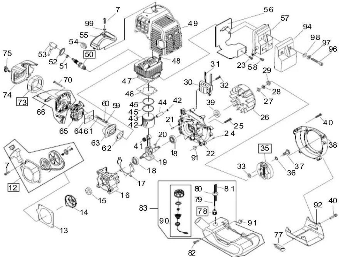
| Pos. | Art.-No | Pos. | Art.-No | Pos. | Art.-No | ||
| 7 | 462555 | 31 | 411727 | 52 | 462593 | 78 | 462619 |
| 12 | 462554 | 32 | 463222 | 53 | 462594 | 79 | 411749 |
| 13 | 462556 | 33 | 411728 | 54 | 462595 | 80 | 411750 |
| 14 | 462557 | 35 | 411729 | 55 | 411738 | 81 | 411751 |
| 15 | 462558 | 36 | 462576 | 56 | 411739 | 82 | 462623 |
| 16 | 411721 | 37 | 462577 | 57 | 411740 | 83 | 411730 |
| 17 | 463215 | 38 | 462578 | 58 | 462599 | 90 | 462631 |
| 18 | 412180 | 39 | 463219 | 59 | 411741 | 91 | 462632 |
| 19 | 411722 | 40 | 463247 | 60 | 411742 | 92 | 411752 |
| 20 | 462563 | 41 | 411731 | 61 | 411743 | 94 | 411753 |
| 21 | 462564 | 42 | 411732 | 62 | 411744 | 96 | 411754 |
| 22 | 411723 | 43 | 411733 | 63 | 411745 | 97 | 411755 |
| 23 | 411724 | 44 | 463227 | 64 | 411746 | 98 | 411756 |
| 24 | 462564 | 45 | 463228 | 65 | 411747 | 99 | 411757 |
| 25 | 462566 | 46 | 411734 | 66 | 411768 | ||
| 26 | 411725 | 47 | 411735 | 70 | 462611 | ||
| 27 | 463220 | 48 | 463230 | 73 | 462614 | ||
| 28 | 462568 | 49 | 411736 | 74 | 411748 | ||
| 29 | 462569 | 50 | 411737 | 75 | 462616 | ||
| 30 | 411726 | 51 | 462592 | 77 | 462618 |
| Count ry | Company | Telephon e Fax | |
| A | AL-KO Kober Ges.m.b.H. | (+43) 35 78 / 2 515100 | (+43) 35 78 / 2515 30 |
| AUS | AL-KO International PTY. LTD | (+61) 3 / 97 67- 3700 | (+61) 3 / 97 67- 3799 |
| B / L (+32)16 / 80 54 27Eurogarden NV | (+32)16 /80 54 25 | ||
| BG | Valerii S&M Group SJ | (+359) 2 942 34 02 | (+359) 2 942 34 10 |
| CH | AL-KO Kober AG | (+41) 56 / 418 31 50 | (+41) 56 / 418 31 60 |
| CZ | AL-KO Kober Spol.sr.o. | (+420) 382 / 21 03 81 | (+420) 382 / 21 27 82 |
| D | AL-KO Geräte GmbH | (+49) 82 21/ 2 03 - 0 | (+49) 82 21/ 2 03 -138 |
| DK | AL-KO Ginge A/S | (+45) 98 82 10 00 | (+45) 98 82 54 54 |
| EST/LT/LV | AL-KO Kober SIA | (+371) 674 09 330 | (+371) 678 07 018 |
| F | AL-KO S.A.S. | (+33) 3 / 85 -76 35 40 | (+33) 3 / 85 -76 35 88 |
| GB | Rochford Garden Machinery Ltd. | (+44)19 63 / 82 80 50 | (+44)19 63 / 82 80 52 |
| H (+36) 29 / 53 70 50AL-KO KFT | (+36) 29 / 53 70 51 | ||
| HR | (+385) 1 3096 567Brun.ko.-prom d.o.o. | ||
| I | AL-KO Kober GmbH / SRL | (+39) 039 / 9 32 93 11 | (+39) 039 / 9 32 93 90 |
| IN | (+91) 33 2287 4206AGRO-COMMERCIAL | ||
| IQ | Gulistan Com | (+946) 750 450 80 64 | |
| IRL (+44) 2890 813 121Cyril Johnston & Co. Ltd. | (+44) 2890 914 220 | ||
| LY | ASHOFAN FOR AGRICULT. ACC. | (+218) 512 660 209 | (+218) 512 660 209 |
| MA (+212) 022 447 128BADRA Sarl | (+212) 022 447 130 | ||
| MK (+389) 2 255 18 01Techno Geneks | (+389) 2 252 01 75 | ||
| N (+47) 64 86 25 50AL-KO GINGE A/S | (+47) 64 86 25 54 | ||
| NL | O.DE LEEUW GROENTECHNIEK | (+31) 38 / 444 6160 | (+31) 38 / 444 6358 |
| PL | AL-KO Kober z.o.o. | (+48) 61 / 8 16 19 25 | (+48) 61 / 8 16 19 80 |
| RO | OMNITECH Technology SRL | (+4) 021 326 36 72 | (+4) 021 326 36 79 |
| RUS | OOO AL-KO Kober | (+7) 499 / 168 87 18 | (+7) 499 /966 00 - 00 |
| RUS | AL-KO St. Petersburg GmbH | (+7) 8 12 / 4 46 10 75 | (+7) 8 12 / 4 46 10 75 |
| S | AL-KO Ginge Svenska AB | (+46) (0) 3157 35 80 | (+46) (0) 3157 56 20 |
| SK | AL-KO Kober Slovakia Spol.s.r.o. | (+421) 2 / 45 99 4112 | (+421) 2 / 45 64 8117 |
| SLO | Darko Opara s.p. | (+386) 1 722 58 50 | (+386) 1 722 58 51 |
| SRB (+381) 34 308 000Agromarket d.o.o. | (+381) 34 308 16 | ||
| TR (+90) 232 4580586ZIMAS A.S. | (+90) 232 4572697 | ||
| UA | TOV AL-KO Kober | (+380)44/4923396 | (+380)44/4923397 |