
BC 223 B - String Trimmer AL-KO - Free user manual and instructions
Find the device manual for free BC 223 B AL-KO in PDF.

| Product type | Thermal grass trimmer |
| Brand | AL-KO |
| Model | BC 223 B |
| Dry weight | 5.5 kg |
| Engine type | 2-stroke, air-cooled, 1 cylinder |
| Displacement | 22.5 cm³ |
| Maximum power | 0.7 kW (0.95 HP) at 8000 min⁻¹ |
| Idle speed | 3200 ±200 min⁻¹ |
| Full throttle speed | 9500 min⁻¹ |
| Fuel tank capacity | 550 cm³ |
| Gasoline/oil mixing ratio | 50:1 |
| Cutting width (spool) | 415 mm |
| Cutting line diameter | 2.5 mm |
| Blade diameter (3 teeth) | 255 mm |
| Sound pressure level LpA | 94.9 dB(A) (K=3.0 dB) |
| Guaranteed sound power | 112 dB(A) |
| Vibration level (left/rear handle) | 4.83 m/s² / 3.52 m/s² (K=1.5 m/s²) |
| Spark plug | CMR6A, electrode gap 0.6-0.7 mm |
| Ignition type | Electronic |
| Clutch | Centrifugal |
| Intended use | Cutting soft grass, vegetation; with blade: brushwood |
| Delivery contents | Hex key, spark plug wrench, screws, 3-tooth blade, guard |
Frequently Asked Questions - BC 223 B AL-KO
User questions about BC 223 B AL-KO
0 question about this device. Answer the ones you know or ask your own.
Ask a new question about this device
Download the instructions for your String Trimmer in PDF format for free! Find your manual BC 223 B - AL-KO and take your electronic device back in hand. On this page are published all the documents necessary for the use of your device. BC 223 B by AL-KO.
USER MANUAL BC 223 B AL-KO
natural_image
Two metal carbocage levers with attached harnesses and metal fittings (no text or symbols visible)DE
GB
NL
FR
ES
IT
SI
HR
RS
PL
CZ
SK
HU
DK
SE
NO
FI
EE
LV
LT
RU
UA


Inhaltsverzeichnis
Deutsch 8
English....27
Nederlands 45
Français....64
Español 84
Italiano....104
Slovenščina 123
Hrvatski....141
Српски....159
Polski....178
Česky 198
Slovenská 216
Magyarul....234
Dansk 253
Svensk....271
Norsk 289
Suomi 307
Eesti 325
Latviešu 342
Lietuvių 361
Русский 380
Україна....401
© 2019
AL-KO KOBER GROUP Kötz, Germany
This documentation or excerpts therefrom may not be reproduced or disclosed to third parties without the express permission of the AL-KO KOBER GROUP.


4.2 Montage Motorsense BC 223 L-S..... 15
4.2 Montage Motorsense BC 223 L-S
4.2.1 "Loop"-Griff montieren (09)
6.3 Motor starten/stoppen BC 223 L-S (13)
Kaltstart
BC 223 B (Motorsense)
BC 223 L-S (Grastrimmer)
EU-Richtlinien
2006/42/EG
2014/30/EU
2000/14/EG
1 About these operating instructions ..... 27
1.1 Symbols on the title page.... 28
1.2 Legends and signal words ...... 28
2 Product description 28
2.1 Intended use 28
2.2 Possible foreseeable misuse .... 28
2.3 Residual dangers 28
2.4 Safety and protective devices ..... 29
2.5 Symbols on the appliance 29
2.6 Scope of supply (01, 08) ...... 29
2.7 Product overview (01, 08) ...... 30
2.8 Approved cutting tools.... 30
3 Safety instructions 31
3.1 Operator 31
3.2 Personal protective equipment...... 31
3.3 Safety in the workplace 31
3.4 Appliance safety.... 31
3.5 Safety of persons, animals and property 31
3.6 Vibration load 32
3.7 Handling of petrol and oil 32
4 Installation.... 33
4.1 Assembling brushcutter BC 223 B ..... 33
4.1.1 Mounting the "bike" handle (02, 03) 33
4.1.2 Mounting the spool head (04)..... 33
4.1.3 Fitting the blade (05).... 33
4.1.4 Installing guard plate (06) ...... 34
4.2 Assembling brushcutter BC 223 L-S .. 34
4.2.1 Installing loop handle (09) ...... 34
4.2.2 Installing the spool (10) 34
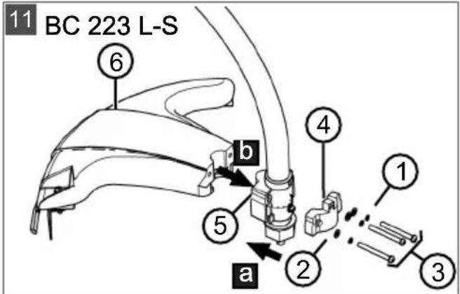
4.2.3 Installing guard plate (11) ...... 34
4.2.4 Assembling shaft (12).... 34
5 Start-up 34
5.1 Mixing and pouring in the petrol/oil mixture 34
6 Operation.... 35
6.1 Preparation 35
6.2 Starting/stopping the engine, BC 223 B (07).... 35
6.3 Starting/stopping the engine, BC 223
L-S (13).... 36
6.4 Prolonging the cutting line during operation (14) 37
7 Working behaviour and working technique.... 37
7.1 Trimming.... 37
7.2 Mowing 37
8 Maintenance and care.... 37
8.1 Cleaning/replacing the air filter (16).... 38
8.2 Checking/replacing fuel filter (17) ..... 38
8.3 Maintaining the spark plug (18) ..... 38
8.4 Sharpening line cutter (19) 39
8.5 Maintenance schedule.... 39
9 Help in case of malfunction 40
10 Transport.... 41
11 Storage.... 42
12 Disposal.... 42
13 Technical data.... 42
14 After-Sales / Service.... 43
15 Guarantee 44
16 Translation of the original EU/EC declaration of conformity.... 44
1 ABOUT THESE OPERATING INSTRUCTIONS
The German version is the original operating instructions. All additional language versions are translations of the original operating instructions.
■ Always safeguard these operating instructions so that they can be consulted if you need any information about the appliance.
■ Only pass on the appliance to other persons together with these operating instructions.
■ Comply with the safety and warning information in these operating instructions.
1.1 Symbols on the title page
Symbol Meaning

It is essential to read through these operating instructions carefully before start-up. This is essential for safe working and trouble-free handling.

Operating instructions

Never operate the petrol powered device in the vicinity of open flames or heat sources.
1.2 Legends and signal words

DANGER!
Denotes an imminently dangerous situation which will result in fatal or serious injury if not avoided.

WARNING!
Denotes a potentially dangerous situation which can result in fatal or serious injury if not avoided.

CAUTION!
Denotes a potentially dangerous situation which can result in minor or moderate injury if not avoided.
IMPORTANT!
Denotes a situation which can result in material damage if not avoided.

NOTE
Special instructions for ease of understanding and handling.
2 PRODUCT DESCRIPTION
2.1 Intended use
The brushcutter is intended for cutting soft grass and similar vegetation. The trimmer must be guided parallel to the ground.
The brushcutter is available in two versions; observe the instruction steps appropriate to your appliance:
■ BC 223 B: Brushcutter with "bike" handle; use with spool or blade. When using a blade, the brushcutter is also suitable for mowing thicker herbaceous plants, young under-growth and shrubs.
■ BC 223 L-S: Grass trimmer with "loop" handle; used exclusively with a spool.

NOTE
Local and national regulations in working hours, noise control and exhaust emissions can restrict the use of the appliance. Please obtain and observe the applicable information!
This appliance is intended solely for use in non-commercial applications. Any other use (as well as unauthorised conversions or add-ons) are regarded as contrary to the intended use and will result in exclusion of the warranty as well as loss of conformity (CE mark); the manufacturer will thus decline any responsibility for damage and/or injury suffered by the user or third parties.
2.2 Possible foreseeable misuse
■ Do not cut any shrubs, hedges, trees or flowers.
- Do not lift the appliance off the ground during operation.
Use the appliance only with the manufacturer's original cutting tools (see chapter 2.8 "Approved cutting tools", page 30).
2.3 Residual dangers
Even during correct use of the appliance, there is always a certain residual risk that cannot be excluded. Depending on the use, the following potential risks can be derived from the type and construction of the appliance:
■ Throwing out of cuttings, soil and small stones
■ Throwing out of cut-off parts of the cutting line
■ Inhalation of cuttings particles if no breathing protection is worn.
■ Damage to the hearing if no hearing protection is worn.
■ Cutting injuries when reaching into the rotating cutting line or the rotating blade
2.4 Safety and protective devices

WARNING!
Risk of injury
Defective and disabled safety and protective devices can lead to serious injury.
■ Have any defective safety and protective devices repaired.
■ Never disable safety and protective devices.
Emergency stop
In an emergency, switch off the engine with the on/off switch.
Guard plate
The guard plate protects the operator from contact with the rotating cutting line and objects that are thrown out.
Loop handle with spacer
The "loop" handle ensures that the operator's feet do not get into the vicinity of the rotating cutting line.
2.5 Symbols on the appliance
Symbol Meaning

Hot surface. Do not touch!

Danger of fire! Pay special attention when handling petrol!

Pay special attention when handling this product.

Read the operating instructions before starting operation.

Wear a protective helmet, ear defenders and eye protection!

Danger due to objects being thrown out!
Symbol Meaning

The distance between the appliance and persons not involved in the work must be at least 15 m in the entire area around the user.

On no account may the brushcutter be operated with rotating blade!

For BC 223 B only: On no account may the brushcutter be operated with a saw blade!

Danger during tool run-down.

Observe the maximum speed and direction of rotation of the shaft for the cutting tool.

Operate the brushcutter only with spool and cutting line!

Wear sturdy shoes!

Wear protective gloves!
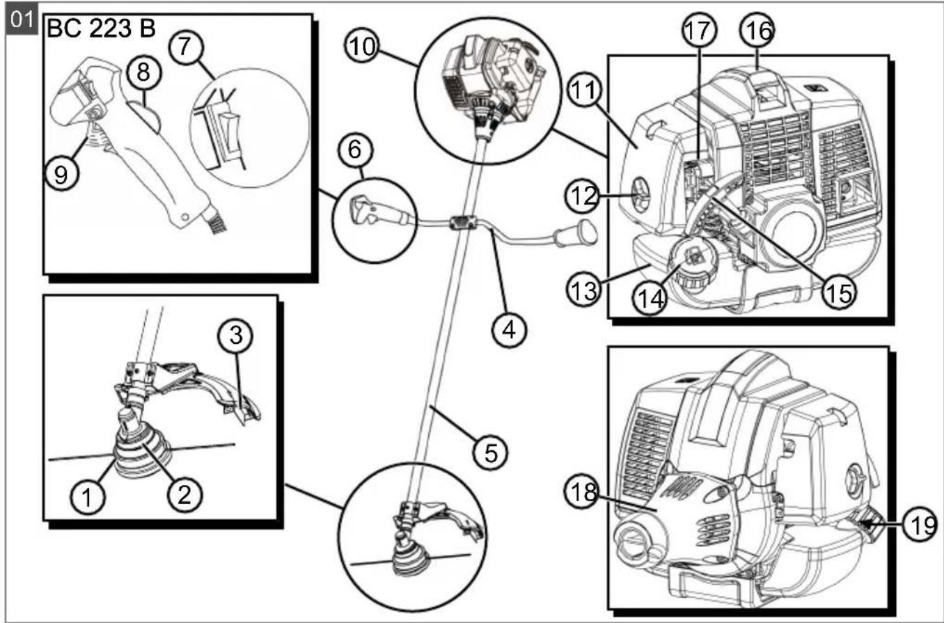
2.6 Scope of supply (01, 08)
The scope of supply includes the components listed in the product overview, see chapter 2.7 "Product overview (01, 08)", page 30. The following are also included in the scope of supply:
Allen key
- Spark plug spanner
Allen screws
■ 3-toothed blade (BC 223 B)
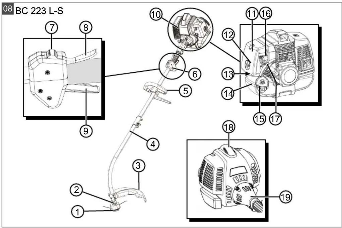
2.7 Product overview (01, 08)
BC 223 B (01)
No. Component
| 1 Spool head | |
| 2 Angular transmission | |
| 3 Guard plate with line cutter | |
| 4 Bike handle | |
| 5 Shaft | |
| 6 Combination handle with: | |
| 7 | ■ On/off switch for engine (START/ STOP) |
| 8 | ■ Locking button |
| 9 | ■ Throttle lever |
| 10 Engine block with: | |
| 11 | ■ Air filter housing |
| 12 | ■ Air filter screw |
| 13 | ■ Fuel tank |
| 14 | ■ Cap of the fuel tank |
| 15 | ■ Starter handle |
| 16 | ■ Spark plug cover |
| 17 | ■ Choke lever |
| 18 | ■ Housing flange |
| 19 | ■ Primer |
BC 223 L-S (08)
| No. | Component |
| 1 | Spool head |
| 2 | Drive shaft |
| 3 | Guard plate with line cutter |
| 4 | 2-piece shaft |
| 5 | Loop handle with spacer |
| 6 | Combination handle with: |
| 7 | ■ On/off switch (START/STOP) |
| 8 | ■ Locking button |
| 9 | ■ Throttle lever |
| 10 | Engine block with: |
No. Component
| 11 | ■ Air filter housing |
| 12 | ■ Air filter screw |
| 13 | ■ Primer |
| 14 | ■ Fuel tank |
| 15 | ■ Cap of the fuel tank |
| 16 | ■ Choke lever |
| 17 | ■ Starter handle |
| 18 | ■ Spark plug cover |
| 19 | ■ Housing flange |
2.8 Approved cutting tools
Only the OEM cutting tools listed here may be used:
■ BC 223 B spool: article no. 112406
■ BC 223 L-S spool: article no. 112880
■ BC 223 B 3-toothed blade: article no. 112405

DANGER!
Danger from cutting tools!
Non-approved cutting tools (e.g. multi-part metallic cutting tools with revolving chains and blades) and damaged cutting tools (e.g. cracks, spalling) can result in very serious injuries or even death.
■ Use only the approved OEM cutting tools.
- Replace damaged cutting tools immediately.
The use of non-approved cutting tools is contrary to the intended use (see chapter 2.1 "Intended use", page 28)!
3 SAFETY INSTRUCTIONS

CAUTION!
Danger of hearing damage
The appliance is extremely loud during operation. This can cause hearing damage to the operator and to persons and animals in the vicinity.
■ Only work when wearing hearing protection.
- Maintain a safe distance to persons or animals, or switch off the appliance if persons or animals approach.

NOTE
It is essential to familiarise yourself with the operation of the appliance. In particular, learn how the appliance can be immediately stopped.
3.1 Operator
■ Young people under 16 years of age and people who do not know the operating instructions are not allowed to use the appliance. Heed any country-specific safety regulations concerning the minimum age of the user.
If you are working with such an appliance for the first time: Have the salesperson or another expert explain the operation of the appliance. Or attend a course.
To operate the appliance, you must be rested and in good physical and mental health. If you must not exert yourself for health reasons, ask your doctor whether it is possible to work with this appliance.
■ Do not operate the appliance if you are under the influence of alcohol, drugs or medication.
3.2 Personal protective equipment
■ Wear clothing and protective equipment in accordance with the regulations in order to avoid injuries to the head and limbs, as well as to avoid hearing impairment.
■ The clothing must be appropriate (tightly fitting) and must not restrict movements.
■ The personal protective equipment comprises:
■ Hearing protection (e.g. ear defenders, especially when working for than 2.5 hours a day)
- Protective glasses
■ Sturdy working gloves, vibration and shock absorbent
■ Safety boots with high-grip sole and steel toe caps
3.3 Safety in the workplace
■ Only operate the appliance out of doors and never in enclosed spaces.
■ Only work during daylight or under very bright artificial light.
Before working, Remove any dangerous products and objects from the working area, e.g. branches, broken glass, sharp-edged objects, pieces of metal, stones, before starting work.
■ Make sure you are standing safely. Avoid wet, slippery ground.
■ When working, move cautiously and slowly. Do not run. Watch out for obstacles.
3.4 Appliance safety
■ Only use the appliance under the following conditions:
The appliance is not dirty, especially not with petrol and oil.
The appliance show no signs of damage, especially the protective grille.
■ All controls function properly.
All accessory parts intended for the respective operating mode are fitted on the appliance.
- Do not overload the appliance. It is intended for light work in the private sector. Overload can lead to damage to the appliance.
■ Never block the vacuum and ventilation grille during operation in order to avoid any overheating of the engine.
- Immediately switch off the appliance if the engine begins to vibrate abnormally or strongly. There is an appliance fault in this case.
■ Never operate the appliance with worn or defective parts. Always replace defective parts with original spare parts from the manufacturer. If the appliance is operated with worn or defective parts, guarantee claims against the manufacturer are excluded.
3.5 Safety of persons, animals and property
■ Use the appliance only for the purposes for which it is intended. Any non-intended use can lead to injury and property damage.
■ Switch on the appliance only when there are no persons or animals in the working area.
- Maintain a safe distance to persons or animals, or switch off the appliance if persons or animals approach.
■ Never direct the exhaust gas jet of the engine towards persons and animals or towards inflammable products and objects.
- Do not reach into the vacuum and vent grilles when the engine is running. Injuries can occur due to rotating appliance parts.
■ Always switch off the appliance when not in use, e.g. when changing the work area, during service and maintenance, and when filling with the petrol/oil mixture.
- Immediately switch off the appliance if there is an accident in order to avoid further injuries and/or property damage.
■ Never operate the appliance with worn or defective parts. Worn or defective appliance parts can cause serious injuries.
- Keep the appliance out of the reach of children.
3.6 Vibration load
■ Danger due to vibration
The actual vibrations emitted during the use of the appliance may deviate from those stated by the manufacturer. Observe the following influencing factors before or during use:
Is the appliance being used as intended?
Is the material being cut or processed in the proper manner?
Is the appliance in a proper condition of use?
Is the cutting tool properly sharpened or is the correct cutting tool installed?
Are the handle grips and any optional vibration grips mounted, and are they firmly attached to the appliance?
■ Only operate the tool at the combustion engine speed required for the respective work. Avoid using the maximum speed in order to reduce noise and vibrations.
The noise and vibrations of the tool may increase due to improper use and maintenance. This leads to health damage. In this case, immediately switch off the tool and have it repaired by an authorised service workshop.
The degree of stress due to vibration depends on the work to be performed or on the use of the tool. Estimate the stress and plan
appropriate work breaks. This considerably reduces stress due to vibration over the entire working time.
- Extensive use of the tool exposes the operator to vibrations, which can lead to circulatory issues ("white fingers"). To avoid this risk, wear gloves and keep your hands warm. If any symptoms of "white fingers" occur, immediately consult a physician. These symptoms include: Numbness, loss of feeling, tingling, itching, pain, reduced muscular strength, changes in the colour or condition of the skin. Normally these conditions affect the fingers, hands or pulse. The risk increases at low temperatures (below approx 10°C).
Take long breaks during your working day so you can recover from the noise and the vibrations. Plan your work in such a way that the use of appliances that generate strong vibrations is spread over several days.
If you notice an unpleasant sensation or discoloration of the skin on your hands when using the tool, stop work immediately. Take sufficient work breaks. Without sufficient breaks, a hand/arm vibration syndrome can occur.
- Minimise your risk of being exposed to vibrations. Maintain the tool according to the instructions in the operating instructions.
If the tool is used frequently, contact your dealer to purchase anti-vibration accessories (e.g. handles).
■ Define how the vibration load can be limited in a work plan.
3.7 Handling of petrol and oil
Risk of explosion and fire:
An escaping petrol/air mixture can cause an explosive atmosphere. Deflagration, explosion and fire can lead to serious and even fatal injuries if fuel is not handled properly. Observe the following:
- Do not smoke when dealing with petrol.
- Only handle petrol out of doors and never in enclosed spaces.
It is essential to heed the code of conduct stated below.
■ Only transport and store petrol and oil in containers approved for that purpose. Ensure that children have no access to stored petrol and oil.
In order to avoid ground contamination (environmental protection) when filling, ensure
that no petrol or oil enters the soil. Use a funnel for filling.
■ Never fill the appliance in enclosed spaces. Petrol vapours may gather at ground level, and thereby result in a deflagration or even an explosion.
- Immediately wipe any spilled petrol off the appliance and the ground. Allow textiles used to wipe off petrol to dry in a well ventilated place before disposing of them. Otherwise, sudden self-ignition may occur.
If petrol has been spilled, petrol vapours occur. For this reason, do not start the engine at the same location and move it at least 3 m away.
- Avoid skin contact with mineral oil products. Do not inhale petrol vapours. When filling, always wear protective gloves. Change and clean protective clothing regularly.
■ Ensure that your clothing does not come into contact with petrol. If petrol has got onto your clothing, change it immediately.
■ Never fill the appliance while the engine is running or hot.
4 INSTALLATION

WARNING!
Danger if assembly is not carried out completely!
Operation of an incompletely assembled appliance can result in serious injury.
■ Only operate the appliance when it is fully assembled.
- Check that all safety and protective devices are in place and functioning correctly before switching on.

WARNING!
Risk of injury due to detaching appli- ance parts
Appliance parts detaching during operation can lead to serious injury.
- Attach the cutting tools so that they cannot come loose during operation.
4.1 Assembling brushcutter BC 223 B
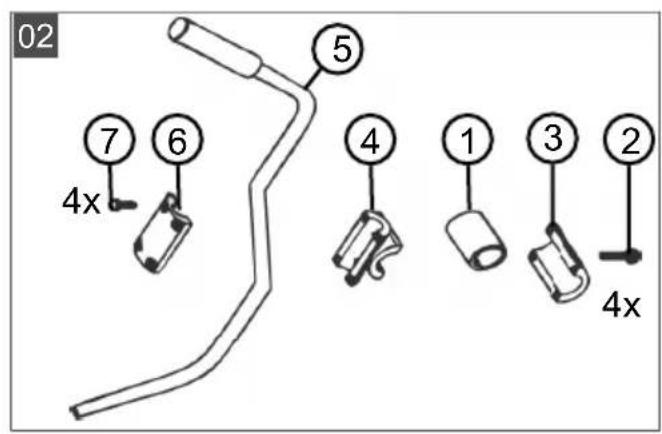
4.1.1 Mounting the "bike" handle (02, 03)
-
Place rubber sleeve (02/1) over shaft.
-
Use the four Allen screws (02/2) to fasten the lower bearing shell (02/3) and the handle bracket (02/4) over the rubber sleeve (02/1).
- Insert the "bike" handle (02/5) into the handle bracket (02/4).
- Use the four Allen screws (02/7) to fasten the upper bearing shell (02/6) on the handle bracket (02/4).
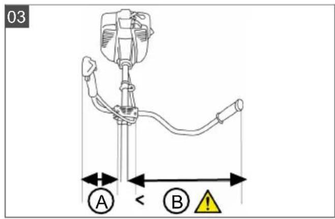
- Align the "Bike" handle in such a way that distance A is smaller than distance B (03/A, 03/B).
Note: Always guide the trimmer to the right of your body using the "Bike" handle. Both distances are correct when the middle of the cutting head coincides with the middle of the body.
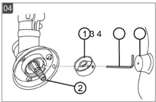
4.1.2 Mounting the spool head (04)
- Place driver plate (04/1) onto guide pin (04/2) of drive shaft.
- To lock, insert Allen key (04/3) into hole of driver plate (04/1).
- Screw spool head (04/4) onto the drive shaft and tighten.
Note: Left-hand thread. Tighten the spool in an anti-clockwise direction.
4.1.3 Fitting the blade (05)

WARNING!
Danger of serious injury!
The blade can become undone during operation and cause serious injury due to a locking nut that starts to turn easily.
- Immediately replace the locking nut if it becomes easy to turn.
- Place the brushcutter so that the cutting head is pointing upwards.
- Place driver plate (05/1) onto guide pin (05/2) of drive shaft.
- Place the blade (05/3) on the driver plate (05/1) so that the hole in the blade lies precisely on the guide circle on the driver plate.
- Place the flange (05/4) onto the blade (05/3) so that the flat side points towards the cutting blade.
- Put on the serrated washer (05/5).
- Screw the fastening nut (05/6) onto the guide pin (05/2). To do this, insert the Allen key (05/7) into the holes provided and tighten with the spark plug spanner.
Note: Left-hand thread.
- Secure the fastening nut (05/6) with the split pin (05/8).
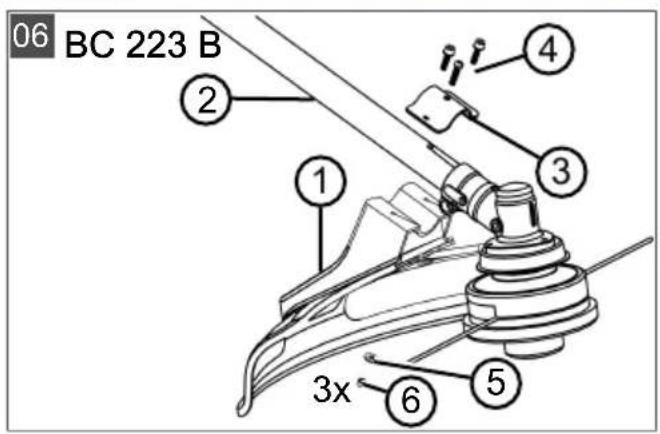
4.1.4 Installing guard plate (06)
- Place the guard plate (06/1) on the shaft (06/2).
- Position the half clamp (06/3) on the shaft (06/2) from the other side, and guide three Allen screws (06/4) through the half clamp, shaft and guard plate.
- Firmly tighten all components with three washers (06/5) and three fastening nuts (06/6).
4.2 Assembling brushcutter BC 223 L-S
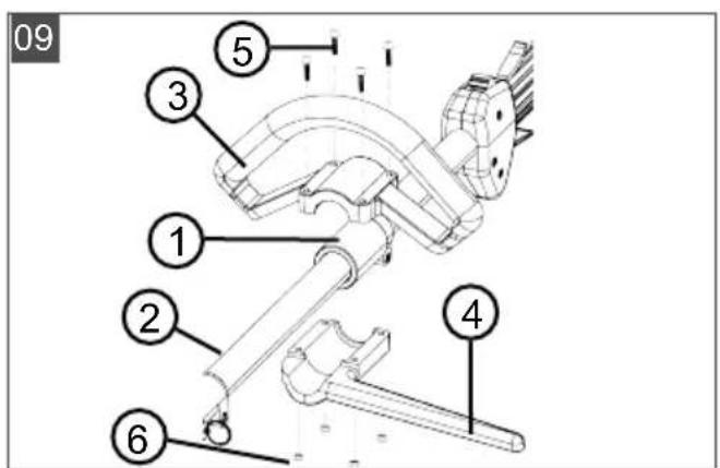
4.2.1 Installing loop handle (09)
- Place rubber sleeve (09/1) over shaft (09/2).
- Place loop handle (09/3) from above and spacer (09/4) from below onto the rubber sleeve.
- Insert an Allen screw (09/5) from above and screw on a nut (09/6) from below, then tighten slightly. Repeat this step with the other Allen screws and nuts.
- Tighten all Allen screws securely.
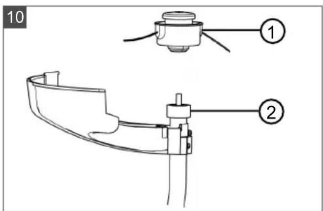
4.2.2 Installing the spool (10)
- Screw spool (10/1) onto the drive shaft (10/2) and tighten.
Note: Right-hand thread. Tighten spool clockwise.
4.2.3 Installing guard plate (11)
- Push a spring lock washer (11/1) and a washer (11/2) onto the screw (11/3) M5 x 45 mm.
- Insert all three screws with spring lock washer and washer through front attachment part (11/4) and position on the shaft (11/a).
- Position rear attachment part (11/5) and guard plate (11/6) on the shaft (11/b).
- Tighten the screws securely.
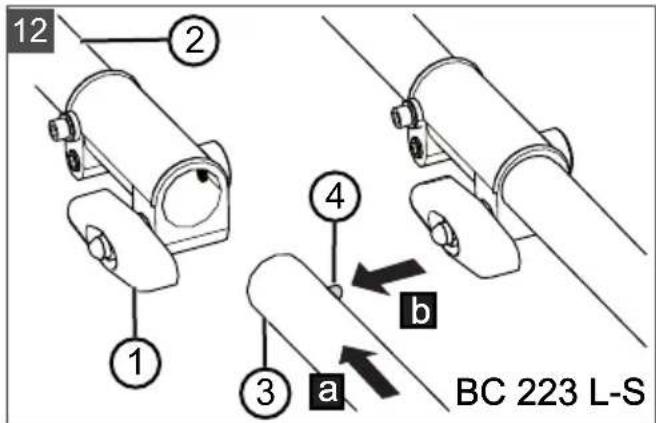
4.2.4 Assembling shaft (12)
The shaft of the brushcutter comes in two parts to save space during storage.
Pushing the two shaft halves together
-
Loosen clamping screw (12/1) of upper shaft half (12/2).
-
Insert the lower shaft half (12/3) into the coupling sleeve up to the limit stop (12/a) until the knob (12/4) audibly engages. Note:
The hollow shaft in the lower shaft half must engage in the square of the upper shaft half. Twist upper and lower shaft half slightly during assembly, if necessary.
- Tighten the clamping screw (12/1) again.
Pulling the two shaft halves apart
- Loosen the clamping screw (12/1).
- To release, press (12/b) the knob (12/4) and pull the shaft halves apart.
5 START-UP

NOTE
Inspect the appliance for damage every day before starting work, if it is dropped or is subjected to other impacts. Have any damage repaired before putting the appliance into operation.
5.1 Mixing and pouring in the petrol/oil mixture
IMPORTANT!
Danger of engine damage
Pure petrol will result in damage and complete failure of the engine. Guarantee claims against the manufacturer are excluded in this case.
■ Always operate the engine using the specified petrol/oil mixture ratio.
Producing the petrol/oil mixture
The 2-stroke engine requires:
Lead-free, fresh petrol with an octane rating of at least 90. Petrol stored for longer than 2 months will lead to deposits and malfunctions of the engine.
■ High-quality synthetic oil for 2-stroke engines Prepare a petrol/oil mixture in a ratio of 50:1 using these two constituents:
| Mixing ratio Petrol | [li-tres] | 2-stroke oil [millilitres] |
| 50 parts petrol: 1 part 2-stroke oil | 1 l 20 ml | |
| 3 l 60 ml | ||
| 5 l 100 ml |
- Pour the petrol and 2-stroke oil into a fuel mixing bottle (quantities, see table, depending on the size of the fuel mixing bottle).
- Close the fuel mixing bottle and shake vigorously several times so that the petrol and oil can mix thoroughly.
Pouring in the petrol/oil mixture (15)
- Place the appliance on a level, horizontal surface. The cap of the fuel tank must be facing upwards.
- Wipe the fuel tank cap (15/1), the fuel tank (15/2) and the surrounding appliance parts clean so that no dirt can get into the fuel tank when the petrol/oil mixture is poured in.
- Open the fuel tank cap slowly so the pressurised petrol/air mixture can slowly escape from the fuel tank into the atmosphere. Leave the cap hanging on the fuel tank.
- Insert a funnel (15/3) into the filler neck (15/4) of the fuel tank.
- Pour the prepared petrol/oil mixture from the fuel mixing bottle (15/5) into the fuel tank up to the lower edge of the filler neck, but not higher.
- Remove the funnel and screw on the cap finger-tight.
- Wipe any spilled petrol/oil mixture off the appliance and the surface.
6 OPERATION
6.1 Preparation
Before starting
Place the trimmer level and free of obstacles on the ground. The cutting tool must not be touching any objects or the ground.
When starting
- Do not stand on the shaft to avoid damage to the shaft and/or the drive shaft inside the shaft.
■ Make sure you are standing securely and hold the trimmer firmly at the housing flange.
Positions of the choke lever

CHOKE RUN

Cold start
If the engine is cold, i.e. if it has not been in use for more than 5 minutes, a “cold start” is carried out.
Warm start
If the engine is still warm from use, i.e. shortly after it was switched off, a "warm start" is carried out. The choke is not used here.
6.2 Starting/stopping the engine, BC 223 B (07)
Cold start
- Move the on/off switch (07/1) to the START position.
- Setting the throttle lever:
■ Press and hold throttle lever (07/2).
■ Press and hold the locking button (07/3).
■ Release the throttle lever (07/2) – it engages at half throttle.
■ Release locking button (07/3).
- Move the choke lever (07/4) to CHOKE.
- Briefly and firmly press the primer (07/5) approx. 10 times.
- Starting the engine:
■ Press the appliance firmly onto the ground with one hand.
■ With the other hand, pull the starter handle (07/6), first carefully and slowly until resistance is felt, and then firmly and quickly upwards until resistance is felt again (approx. 1 arm length).
- Allow the starter rope to coil up again, but without releasing the starter handle.
■ Repeat the previous step several times until the engine starts, but stalls again.
- Moving the choke lever to RUN:
■ Press the appliance firmly onto the ground with one hand.
■ With the other hand, pull the starter handle (07/6), first carefully and slowly until resistance is felt, and then firmly and quickly upwards until resistance is felt again (approx. 1 arm length).
- Allow the starter rope to coil up again, but without releasing the starter handle.
■ Repeat the previous step several times until the engine starts and runs smoothly.
-
Allow the engine to warm up for a few minutes.
-
Press the throttle lever briefly to disengage the locking button. The engine runs at idle speed.
Note: Press the throttle lever again if the engine no longer runs smoothly.
Warm start
If the engine is still warm from use, i.e. shortly after it was switched off, a "warm start" is carried out. The choke is not used here.
- Move the on/off switch (07/1) to the START position.
- Check that choke lever (07/4) is in the RUN position.
■ Press the appliance firmly onto the ground with one hand.
■ With the other hand, pull the starter handle (07/6), first carefully and slowly until resistance is felt, and then firmly and quickly upwards until resistance is felt again (approx. 1 arm length).
- Allow the starter rope to coil up again, but without releasing the starter handle.
■ Repeat the previous step several times until the engine starts and runs smoothly.
The engine runs at idle speed.
Note: Press the throttle lever again if the engine no longer runs smoothly.
Stopping the engine
- Release the throttle lever (07/2) and let the engine run at idling speed.
- Move the on/off switch (07/1) to the STOP position.
- Wait until the cutting tool has come to a complete standstill.
6.3 Starting/stopping the engine, BC 223 L-S (13)
Cold start
- Move the on/off switch (13/1) to the START position.
2. Setting the throttle lever:
■ Press and hold the locking button (13/2).
■ Press throttle lever (13/3).
- Move the choke lever (13/4) to CHOKE.
- Briefly and firmly press the primer (13/5) approx. 7 to 10 times.
5. Starting the engine:
■ Press the appliance firmly onto the ground with one hand.
■ With the other hand, pull the starter handle (13/6), first carefully and slowly until resistance is felt, and then firmly and quickly upwards until resistance is felt again (approx. 1 arm length).
- Allow the starter rope to coil up again, but without releasing the starter handle.
■ Repeat the previous step several times until the engine starts, but stalls again.
6. Moving the choke lever to RUN:
■ Press the appliance firmly onto the ground with one hand.
■ With the other hand, pull the starter handle (13/6), first carefully and slowly until resistance is felt, and then firmly and quickly upwards until resistance is felt again (approx. 1 arm length).
- Allow the starter rope to coil up again, but without releasing the starter handle.
■ Repeat the previous step several times until the engine starts and runs smoothly.
-
Allow the engine to warm up for a few minutes.
-
Press the throttle lever briefly to disengage the locking button. The engine runs at idle speed.
Note: Press the throttle lever again if the engine no longer runs smoothly.
Warm start
If the engine is still warm from use, i.e. shortly after it was switched off, a "warm start" is carried out. The choke is not used here.
- Move the on/off switch (13/1) to the START position.
- Check that choke lever (13/4) is in the RUN position.
■ Press the appliance firmly onto the ground with one hand.
■ With the other hand, pull the starter handle (13/6), first carefully and slowly until resistance is felt, and then firmly and quickly upwards until resistance is felt again (approx. 1 arm length).
- Allow the starter rope to coil up again, but without releasing the starter handle.
■ Repeat the previous step several times until the engine starts and runs smoothly.
The engine runs at idle speed.
Note: Press the throttle lever again if the engine no longer runs smoothly.
Stopping the engine
- Release the throttle lever (13/3) so that the engine runs at idle speed.
- Move the on/off switch (13/1) to the STOP position.
- Wait until the cutting tool has come to a complete standstill.
6.4 Prolonging the cutting line during operation (14)
The cutting line shortens during operation and frays out.
- Allow the engine to run at full speed.
- Tap (14/a) the spool head (14/1) on the ground from time to time. This unwinds a piece of new cutting line from the spool and cuts off the used end of the cutting line (14/2).
7 WORKING BEHAVIOUR AND WORKING TECHNIQUE
■ Make sure you are standing securely.
■ Never work on a smooth, slippery hill or slope.
■ When working on a slope, always stand below the cutting tool.
■ Always allow the engine to run in the upper speed range during trimming and mowing, as the brushcutter then cuts best.
If the cutting line jams
High grass or scrub can cause the cutting line to jam.
■ Avoiding blockages: Cut long grass in several passes. Always proceed from top to bottom.
In the event of a blockage: Switch off the engine immediately and hold the appliance in the air so that the engine is not damaged.
7.1 Trimming
- Keep the appliance away from delicate plants.
Low trimming
■ Guide the cutter head with a slight forward angle so that the cutting line trims just above the ground.
■ Always trim away from your body.
Trimming at fences and foundations
■ Guide the appliance slowly and carefully so that the cutting line does not come into contact with solid obstacles.

NOTE
Trimming around brick walls, foundations, fences and trees results in increased cutting line wear.
Trimming around tree trunks
■ Guide the appliance slowly and carefully around tree trunks so that the cutting line does not touch the tree bark.
- Trim from left to right around tree trunks.
- Cut grass and weeds with the tip of the cutting line and hold the cutter head with a slight forward angle.
7.2 Mowing
■ Guide the cutter head in a smooth horizontal, arc-shaped movement from one side to the other.
- Hold the cutter head parallel to the ground at all times.
■ Long grass should be mown in several passes. Always proceed from top to bottom.
■ The appliance cuts best at very high speed. Therefore, do not overload the appliance by cutting long grass.
■ Tilt the cutter head at an angle of 30^ to the right to mow with the tip of the cutting line. Walk forwards slowly.
- Do not move the appliance directly against hard obstacles (e.g. walls), but mow sideways. This protects the cutting line.
8 MAINTENANCE AND CARE

DANGER!
Risk of injury or death due to improper maintenance
Maintenance work carried out by unqualified persons and the use of non-approved spare parts can result in serious injuries and even death during operation of the appliance.
- Do not remove or deactivate any safety installations.
■ Use only approved OEM spare parts.
■ Ensure through regular and proper maintenance that the appliance is in a clean and functional condition at all times.

CAUTION!
Risk of injury
Sharp-edged and moving appliance parts can lead to injury.
■ Always wear protective gloves during maintenance, care and cleaning work.
Proper maintenance and care is necessary to ensure the functionality and safety of the appliance. Note the following points:
■ Only carry out maintenance and care work if you have the necessary knowledge and tools.
- Wait until the engine has cooled down completely.
■ Only replace any worn or defective appliance parts with original spare parts from the manufacturer.
- Do not carry out any maintenance and care work that is not described in these instructions for use. Instruct an authorise service workshop to do this work. Any infringements will invalidate the manufacturer's warranty.
The intervals for the maintenance and care work mentioned here can be found in the maintenance schedule (Maintenance schedule).
Use only the approved cutting tools (Approved cutting tools)!
8.1 Cleaning/replacing the air filter (16)
IMPORTANT!
Danger of engine damage
Operation of the engine without air filter will result in serious engine damage!
■ Never operate the appliance without air filter.
■ Clean the air filter at regular intervals.
- Replace a damaged air filter.
- Dismantling the air filter:
■ Loosen the air filter screw (16/1) until the air filter housing cover (16/2) is loose.
■ Pull off the air filter housing cover.
■ Pull the filter sponge (16/3) from the frame (16/4).
- Cleaning the filter sponge (16/3):
■ Squeeze out the filter sponge, then wash out with soap and water. Do not use petrol or other solvents!
-
Allow the filter sponge to dry thoroughly until it contains no more water. A wet filter can make the engine difficult to start.
■ Clean the air filter housing thoroughly using a cloth. -
Replacing the filter sponge (16/3):
- Replace the filter sponge if it is no longer elastic or falls apart.
- Fitting the air filter:
■ Push the filter sponge (16/3) onto the frame (16/4).
■ Push on the air filter housing cover (16/2) and hold in place.
■ Screw in the air filter screw (16/1) until the air filter housing cover is tight.
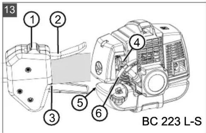
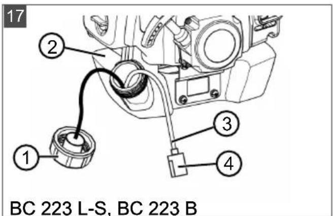
8.2 Checking/replacing fuel filter (17)
The felt-like fuel filter is located in the fuel tank and is plugged onto the vacuum head. If the fuel filter becomes hard, dirty or clogged, less petrol flows to the engine. In this case, the fuel filter must be replaced.
It is recommended that an authorised service workshop carries out this work.
- Preparing the appliance:
■ To empty the fuel tank: Allow the engine to run until it stops itself.
Place the appliance on a level, horizontal surface. The cap (17/1) of the fuel tank (17/2) must be facing upwards.
■ Wipe the fuel tank cap, the fuel tank and the surrounding appliance parts clean so that no dirt can get into the fuel tank.
- Checking/replacing the fuel filter:
■ Unscrew the cap (17/1) of the fuel tank (17/2). Leave the cap hanging on the fuel tank.
■ Use a wire hook to pull the intake head (17/3) out of the fuel tank.
- Inspect the fuel filter (17/4). If the felt has become hard, dirty or clogged: Pull off the fuel filter and push a new fuel filter onto the intake head.
-
Push the intake head into the fuel tank again.
-
Mix and pour in the petrol/oil mixture (see chapter 5.1 "Mixing and pouring in the petrol/oil mixture", page 34).
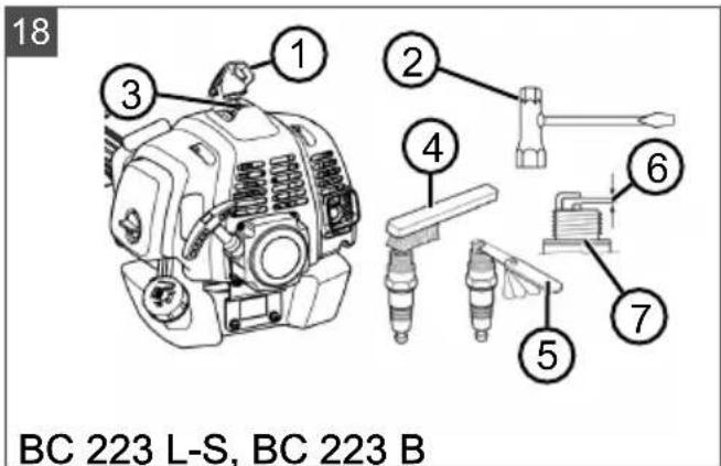
8.3 Maintaining the spark plug (18)
- Removing the spark plug:
■ Remove the spark plug connector (18/1).
■ Unscrew the spark plug (18/3) using a spark plug spanner (18/2).
- Assessing the condition of the spark plug:
If the spark plug is reddish-brown: The engine is working correctly and the spark plug is in order. If necessary: Carefully brush the spark plug clean using a fine wire brush (18/4).
If the spark plug is sooty, oily, encrusted, melted or bridged: The spark plug is defective. Replace the spark plug with a new spark plug. Use the specified spark plug type (see chapter 13 "Technical data", page 42).
If, after a short period of operation, the spark plug is defective again, the engine and the carburettor settings must be checked by an authorised service workshop.
- Check the electrode spacing:
Use a feeler gauge (18/5) to check that the electrode gap (18/6) is 0.6 – 0.7 mm. If not, carefully tap the electrodes closer together or carefully bend them apart.
- If the specified interval is reached or the spark plug is defective:
- Replace the spark plug with a new spark plug. Use the specified spark plug type (see chapter 13 "Technical data", page 42).
- Installing the spark plug:
■ Ensure the spark plug seal ring (18/7) is on the spark plug.
- Screw in the spark plug again by hand and tighten using the spark plug spanner (torque 12 – 15 Nm).
- Push on the spark plug connector again firmly.
8.4 Sharpening line cutter (19)
- Loosen the mounting screws (19/1).
- Clamp the line cutter (19/2) in a vice and sharpen it using a file. File in one direction only.
- Attach the line cutter to the guard plate (19/3) again using the mounting screws. Tighten the mounting screws firmly.
8.5 Maintenance schedule
The following jobs are allowed to be carried out by the user independently. All other maintenance, service and repair work must be carried out in an authorised service workshop.

NOTE
Shorter maintenance intervals than those stated in this table may be necessary in case of severe loading and high temperatures.
| Activity Once | after 5 operating hours | Before each use | Every week | Every 50 operating hours | Every 100 operating hours | If required | Every year before the mowing season |
| Carburettor | |||||||
| Check idling speed X | |||||||
| Air filters | |||||||
| Clean X | |||||||
| Renew X | |||||||
| Spark plug | |||||||
| Check electrode gap, adjust if necessary | X | ||||||
| Renew X X | |||||||
| Cooling air inlet | |||||||
| Clean X X X | |||||||
| Silencer | |||||||
| Visual inspection for condition | X | ||||||
| Fuel tank | |||||||
| Clean X X | |||||||
| Fuel filter | |||||||
| Renew X | |||||||
| Controls | |||||||
| On/off switch, locking button, throttle lever, starter rope | X | ||||||
| All accessible screws (except set screws) | |||||||
| Retighten X X X | |||||||
| Complete appliance | |||||||
| Visual inspection for condition | X | ||||||
| Clean X X X | |||||||
9 HELP IN CASE OF MALFUNCTION

CAUTION!
Risk of injury
Sharp-edged and moving appliance parts can lead to injury.
■ Always wear protective gloves during maintenance, care and cleaning work.
■ Switch the appliance off.

NOTE
For malfunctions that are not listed in this table or that you cannot resolve yourself, please contact our customer service.
| Malfunction Cause Remedy | ||
| Engine does not start, or only starts with difficulty. | Engine start was not carried out properly. | see chapter 6.2 "Starting/stopping the engine, BC 223 B (07)", page 35, see chapter 6.3 "Starting/ stopping the engine, BC 223 L-S (13)", page 36 |
| Spark plug is dirty, defective or the electrode spacing is not right. | see chapter 8.3 "Maintaining the spark plug (18)", page 38 | |
| Malfunction Cause Remedy | ||
| Air filter is dirty. see chapter 8.1 "Cleaning/replacing the air filter (16)", page 38 | ||
| Fuel filter is worn. see chapter 8.2 "Checking/replacing fuel filter (17)", page 38 | ||
| Carburettor settings are not cor-rect. | Contact an authorised service work-shop. | |
| Choke lever is in CHOKE posi-tion. | Move choke lever to RUN. | |
| Engine starts, but the en-gine output is low. | Choke lever is in CHOKE posi-tion. | Move choke lever to RUN. |
| Air filter is dirty. see chapter 8.1 "Cleaning/replacing the air filter (16)", page 38 | ||
| Fuel filter is worn. see chapter 8.2 "Checking/replacing fuel filter (17)", page 38 | ||
| Carburettor settings are not cor-rect. | Contact an authorised service work-shop. | |
| Engine not running smoothly and engine speed not increasing when the throttle is ap-plied. | Spark plug is dirty, defective or the electrode spacing is not right. | see chapter 8.3 "Maintaining the spark plug (18)", page 38 |
| Carburettor settings are not cor-rect. | Contact an authorised service work-shop. | |
| Engine exhaust smoking heavily, appears blue. | Amount of oil in the petrol/oil mixture is too high. | Pour in petrol/oil mixture with correct mixture ratio.see chapter 5.1 "Mixing and pouring in the petrol/oil mixture", page 34 |
| Carburettor settings are not cor-rect. | Contact an authorised service work-shop. | |
| Engine starts abnormally and vibrates strongly. | Appliance/engine parts have come loose and/or are dam-aged. | 1. Stop engine.2. Inspect appliance for damage.3. Check the spark plug, see chap-ter 8.3 "Maintaining the spark plug (18)", page 384. Contact an authorised service workshop. |
10 TRANSPORT
Transporting the appliance between two working areas
- Switch off the engine.
- Put the transport protection onto the blade.
- Hold the brushcutter firmly at the engine block and the handle.
- Walk carefully to the next working area. Take care not to endanger persons or animals.
Transporting the appliance in a vehicle
- If possible: Empty the fuel tank by allowing the engine to run.
- Switch off the engine.
-
Put the transport protection onto the blade.
-
Ensure that the appliance cannot tip over while driving to prevent the petrol/oil mixture from running out:
Place the appliance on the floor of the vehicle so that the fuel tank cap is facing upwards. The fuel tank must be securely closed.
- Fix the appliance to the floor of the vehicle.
11 STORAGE
If you are not going to use the appliance for longer than 2 – 3 months, the following work is necessary to avoid any damage:
- Empty the fuel tank:
- Allow the engine to run until it stops itself. Then there is no longer any petrol/oil mixture in the fuel tank or carburettor, and deposits cannot form.
- Cleaning the appliance:
■ Wipe the entire appliance and accessory parts with a cleaning rag. Do not use petrol or other solvents.
■ Remove any dirt from all appliance openings (including cooling openings for the engine).
-
Oiling the cylinder:
-
Allow the device to cool down completely.
■ Pull off the spark plug connector and unscrew the spark plug (see chapter 8.3
"Maintaining the spark plug (18)", page 38).
-
Drop a little oil into the spark plug opening.
■ Slowly pull on the starter handle so the piston moves and the oil is distributed in the cylinder.
■ Screw in the spark plug again tightly and push on the spark plug connector. -
Put the transport protection onto the blade.
- Store the machine in a cool, dry place.

CAUTION!
Risk of injury
If the appliance is accessible to children and unauthorised persons during storage, this can result in injury.
■ Store the appliance out of the reach of children and unauthorised persons.
12 DISPOSAL

- Petrol and motor oil do not belong in household waste or the public sewer system, but should be collected and disposed of separately.
■ Before disposing of the device you must empty the fuel tank and the engine oil tank!
Packaging, equipment and accessories are made from recyclable materials, and must be disposed of accordingly.
13 TECHNICAL DATA
| BC 223 L-SItem no.: 113691 | BC 223 BItem no.: 113692 | |
| Dry weight 5.1 kg 5.5 kg | ||
| Engine type Air-cooled 2-stroke en- | engine, 1 cylinder | Air-cooled 2-stroke en-gine, 1 cylinder |
| ■ Engine weight 2.8 kg 2.8 kg | ||
| ■ Displacement 22.5 cm | ^3 | 22.5 cm^3 |
| ■ Maximum engine output at 8,000 rpm 0.7 kW (0.95 PS) 0.7 kW (0.95 PS) | ||
| ■ Maximum speed 9500 rpm 9500 rpm | ||
| ■ Idle speed 3,200 ( ± 200) rpm 3,200 ( ± 200) rpm | ||
| ■ Spark plug CMR6A CMR6A | ||
| Ignition electronic electronic | ||
| Clutch Centrifugal clutch Centrifugal clutch | ||
| Tank capacity (petrol) 550 cm | ^3 | 550 cm^3 |
| Petrol Lead-free, minimum 90 | octane | Lead-free, minimum 90 octane |
| Oil Synthetic, for 2-stroke | engines | Synthetic, for 2-stroke engines |
| Fuel mixture ratio [petrol:2-stroke oil] 50:1 50:1 | ||
| Hand grip “Loop” handle “Bike” handle | ||
| Cutting width of the spool (diameter) 415 mm 415 mm | ||
| Diameter of the cutting line 2.0 mm 2.5 mm | ||
| Diameter of the blade | — | 255 mm |
| Speed of the tool | Max. 7,500 ( ± 500) rpm | Max. 8000 ( ± 500) rpm |
| Measured sound pressure level LpA(to EN ISO 22868) | 93.7 dB(A) | 94.9 dB(A) |
| Measurement uncertainty | K = 3.0 dB(A) | K = 3.0 dB(A) |
| Measured sound power L_W A (to EN ISO 22868) | 108.4 dB(A) | 109.0 dB(A) |
| Measurement uncertainty | K = 3.0 dB(A) | K = 3.0 dB(A) |
| Guaranteed sound power | 112.0 dB(A) | 112.0 dB(A) |
| Measured vibration level at the loop handle(to EN ISO 22867) | Front: 6.75 m/s^2 Rear: 8.0 m/s^2 K = 1.5 m/s^2 | Left: 4.83 m/s^2 Rear: 3.52 m/s^2 K = 1.5 m/s^2 |
| Measurement uncertainty | ||
14 AFTER-SALES / SERVICE
In the event of questions of warranty, repair or spare parts, please contact your nearest AL-
KO Service Centre. These can be found on the Internet at:
www.al-ko.com/service-contacts
15 GUARANTEE
We will resolve any material or manufacturing faults on the appliance during the legal warranty period for claims relating to faults, in accordance with our choice either to repair or replace. The legal warranty period is determined by the legislation of the country in which the appliance was purchased.
Our warranty promise applies only if:
■ These operating instructions are heeded
■ The appliance is handled correctly
■ Original spare parts have been used
The warranty becomes void in the case of:
■ Unauthorised repair attempts
■ Unauthorised technical modifications
Non-intended use
The guarantee excludes:
■ Paint damage that can be attributed to normal wear and tear
■ Wear parts that are marked with a frame (x) on the spare parts card
■ Internal combustion engines (these are covered by the guarantee provisions of the corresponding engine manufacturers)
The guarantee period commences with purchase by the first end user. The date on the proof of purchase is decisive. In the event of a guarantee claim, please take this guarantee declaration and the original proof of purchase, and contact your dealer or the nearest authorised customer service centre. This statement does not affect the purchaser's statutory claims for defects against the vendor.
16 TRANSLATION OF THE ORIGINAL EU/EC DECLARATION OF CONFORMITY
We hereby declare, as the exclusively responsible party, that this product in its marketed form meets the requirements of the harmonised EU directives, EU safety standards and the product-specific standards.
Product
Petrol brushcutter/grass trimmer
Serial number
G1071012
Manufacturer
Duly authorised person for technical file
| Andreas Hedrich |
| Ichenhauser Str. 14 |
| D-89359 Kötz |
| Germany |
Type
| BC 223 B (brushcutter) |
| BC 223 L-S (grass trimmer) |
EU directives
| 2006/42/EC |
| 2014/30/EU |
| 2000/14/EC |
Harmonised standards
| EN ISO 11806-1:2011 |
| EN ISO 14982:2009 |
| EN ISO 22868:2011 |
| EN ISO 22867:2011 |
Sound power level
| EN ISO 3744 |
| measured/guaranteed |
| BC 223 B: 109.0 dB(A) / 112 dB(A) |
| BC 223 L-S: 108.4 dB(A) / 112 dB(A) |
Conformity evaluation
| 2000/14/EC Annex V |
Kötz, 16 Jan 2019
Pde UwumAn.C
Peter Kaltenstadler Managing Director
VERTALING VAN DE ORIGINELE GEBRUIKERSHANDLEIDING
Inhoudsopgave
2 PRODUCTOMSCHRIJVING
6.3 Motor starten/stoppen BC 223 L-S (13)
Koude start
www.al-ko.com/service-contacts
15 GARANTIE
BC 223 L-S (grastrimmer)
Geluidsvermogensniveau
EN ISO 3744
www.al-ko.com/service-contacts
15 GARANTIE
| BC 223 B: 109,0 dB (A) / 112 dB (A) |
| BC 223 L-S: 108,4 dB (A) / 112 dB (A) |
Fabricante
www.al-ko.com/service-contacts
15 GARANZIA
| BC 223 L-S (tosaerba) |
Rumorosità
| EN ISO 3744 |
| misurata / garantita |
| BC 223 B: 109,0 dB(A) / 112 dB(A) |
| BC 223 L-S: 108,4 dB(A) / 112 dB(A) |
Costruttore
Peter Kaltenstadler Managing Director
PREVOD ORIGINALNIH NAVODIL
Kazalo vsebine
14 SERVISNA SLUŽBA/SERVIS
www.al-ko.com/service-contacts
15 GARANCIJA
BC 223 B: 109,0 dB(A)/112 dB(A)
BC 223 L-S: 108,4 dB(A)/112 dB(A)
Proizvajalec
AL-KO Geräte GmbH
Ichenhauser Str. 14
D-89359 Kötz
Direktive EU
2006/42/EC
2014/30/EU
2000/14/EC
www.al-ko.com/service-contacts
15 JAMSTVO
Možebitne greške u materijalu ili proizvodnji na uređaju uklonit ćemo tijekom zakonskoga roka zastare za jamstvo na nedostatke prema vlastitom izboru popravljanjem ili zamjenskom dostavom. Rok zastare određuje se prema pravu države u kojoj je uređaj kupljen.
Peter Kaltenstadler Managing Director
www.al-ko.com/service-contacts
15 ГАРАНЦИЈА
www.al-ko.com/service-contacts
15 ZÁRUKA
www.al-ko.com/service-contacts
15 ZÁRUKA
Peter Kaltenstadler Managing Director
AZ EREDETI KEZELÉSI ÚTMUTATÓ FORDÍTÁSA
Tartalomjegyzék
www.al-ko.com/service-contacts
15 GARANCIA
6.2 Start/stop motor BC 223 B (07) .....261
6.3 Start/stop motor BC 223 L-S (13) .....262
11 Opbevaring....267
12 Bortskaffelse......268
14 Kundeservice/service ....269
15 Garanti....269
6.3 Start/stop motor BC 223 L-S (13)
Koldstart
www.al-ko.com/service-contacts
15 GARANTI
Peter Kaltenstadler Managing Director
ÖVERSÄTTNING AV ORIGINALBRUKSANVISNING
6.3 Starta/stoppa motorn BC 223 L-S (13)....280
6.3 Starta/stoppa motorn BC 223 L-S (13)
Kallstart
7.1 Trimming....299
7.2 Klippe....299
7 ARBEIDSFREMTREDEN OG ARBEIDSTEKNIKK
8 VEDLIKEHOLD OG PLEIE

FARE!
Livsfare pga. feil vedlikehold
www.al-ko.com/service-contacts
15 GARANTI
Peter Kaltenstadler Managing Director
KÄÄNNÖS ALKUPERÄISESTÄ KÄYTTÖOHJEESTA
Sisällysluettelo
www.al-ko.com/service-contacts
15 TAKUU JA TUOTEVASTUU
4.2 Trimmeri BC 223 L-S monteerimine... 331
4.2.1 Aaskäepideme paigaldamine (09) 331
4.2.2 Jõhvipooli monteerimine (10) ..... 331
4.2.3 Kaitsekatte monteerimine (11)..... 331
4.2.4 Varre kokkupanek (12) 331
4.2 Trimmeri BC 223 L-S monteerimine
4.2.1 Aaskäepideme paigaldamine (09)
www.al-ko.com/service-contacts
15 GARANTII
www.al-ko.com/service-contacts
15 GARANTIE
BC 223 B: 109,0 dB(A)/112 dB(A)
BC 223 L-S: 108,4 dB(A)/112 dB(A)
Ražotājs
AL-KO Geräte GmbH
Ichenhauser Str. 14
D-89359 Kötz
ES direktivas
2006/42/EC
2014/30/EU
2000/14/EC
www.al-ko.com/service-contacts
15 GARANTIE
www.al-ko.com/service-contacts
15 ГАРАНТИЯ


- Inhaltsverzeichnis
- Montage Motorsense BC 223 L-S
- "Loop"-Griff montieren (09)
- Motor starten/stoppen BC 223 L-S (13)
- Kaltstart
- EU-Richtlinien
- ABOUT THESE OPERATING INSTRUCTIONS
- Symbols on the title page
- Symbol Meaning
- Legends and signal words
- DANGER!
- WARNING!
- CAUTION!
- IMPORTANT!
- NOTE
- PRODUCT DESCRIPTION
- Intended use
- Possible foreseeable misuse
- Residual dangers
- Safety and protective devices
- Risk of injury
- Emergency stop
- Guard plate
- Loop handle with spacer
- Symbols on the appliance
- Scope of supply (01, 08)
- Product overview (01, 08)
- BC 223 B (01)
- Approved cutting tools
- Danger from cutting tools!
- SAFETY INSTRUCTIONS
- Danger of hearing damage
- Operator
- Personal protective equipment
- Safety in the workplace
- Appliance safety
- Safety of persons, animals and property
- Vibration load
- Handling of petrol and oil
- INSTALLATION
- Danger if assembly is not carried out completely!
- Risk of injury due to detaching appli- ance parts
- Assembling brushcutter BC 223 B
- Mounting the "bike" handle (02, 03)
- Mounting the spool head (04)
- Fitting the blade (05)
- Danger of serious injury!
- Installing guard plate (06)
- Assembling brushcutter BC 223 L-S
- Installing loop handle (09)
- Installing the spool (10)
- Installing guard plate (11)
- Assembling shaft (12)
- Pushing the two shaft halves together
- Pulling the two shaft halves apart
- START-UP
- Mixing and pouring in the petrol/oil mixture
- Danger of engine damage
- Producing the petrol/oil mixture
- Pouring in the petrol/oil mixture (15)
- OPERATION
- Preparation
- Before starting
- When starting
- Positions of the choke lever
- Cold start
- Warm start
- Starting/stopping the engine, BC 223 B (07)
- Stopping the engine
- Starting/stopping the engine, BC 223 L-S (13)
- Setting the throttle lever:
- Starting the engine:
- Moving the choke lever to RUN:
- Prolonging the cutting line during operation (14)
- WORKING BEHAVIOUR AND WORKING TECHNIQUE
- If the cutting line jams
- Trimming
- Low trimming
- Trimming at fences and foundations
- Trimming around tree trunks
- Mowing
- MAINTENANCE AND CARE
- Cleaning/replacing the air filter (16)
- Checking/replacing fuel filter (17)
- Maintaining the spark plug (18)
- Sharpening line cutter (19)
- Maintenance schedule
- HELP IN CASE OF MALFUNCTION
- TRANSPORT
- Transporting the appliance between two working areas
- Transporting the appliance in a vehicle
- STORAGE
- DISPOSAL
- AFTER-SALES / SERVICE
- GUARANTEE
- Our warranty promise applies only if:
- The warranty becomes void in the case of:
- The guarantee excludes:
- TRANSLATION OF THE ORIGINAL EU/EC DECLARATION OF CONFORMITY
- VERTALING VAN DE ORIGINELE GEBRUIKERSHANDLEIDING
- Inhoudsopgave
- PRODUCTOMSCHRIJVING
- Koude start
- GARANTIE
- Geluidsvermogensniveau
- GARANZIA
- PREVOD ORIGINALNIH NAVODIL
- Kazalo vsebine
- SERVISNA SLUŽBA/SERVIS
- GARANCIJA
- Proizvajalec
- Direktive EU
- JAMSTVO
- ГАРАНЦИЈА
- ZÁRUKA
- AZ EREDETI KEZELÉSI ÚTMUTATÓ FORDÍTÁSA
- Tartalomjegyzék
- GARANCIA
- Start/stop motor BC 223 L-S (13)
- Koldstart
- GARANTI
- ÖVERSÄTTNING AV ORIGINALBRUKSANVISNING
- Starta/stoppa motorn BC 223 L-S (13)
- Kallstart
- ARBEIDSFREMTREDEN OG ARBEIDSTEKNIKK
- VEDLIKEHOLD OG PLEIE
- FARE!
- Livsfare pga. feil vedlikehold
- KÄÄNNÖS ALKUPERÄISESTÄ KÄYTTÖOHJEESTA
- Sisällysluettelo
- TAKUU JA TUOTEVASTUU
- Trimmeri BC 223 L-S monteerimine
- Aaskäepideme paigaldamine (09)
- GARANTII
- Ražotājs
- ES direktivas
- ГАРАНТИЯ
Brand : AL-KO
Model : BC 223 B
Category : String Trimmer