TWIN 300 - Door/window sensor Schellenberg - Free user manual and instructions
Find the device manual for free TWIN 300 Schellenberg in PDF.

User questions about TWIN 300 Schellenberg
0 question about this device. Answer the ones you know or ask your own.
Ask a new question about this device
Download the instructions for your Door/window sensor in PDF format for free! Find your manual TWIN 300 - Schellenberg and take your electronic device back in hand. On this page are published all the documents necessary for the use of your device. TWIN 300 by Schellenberg.
USER MANUAL TWIN 300 Schellenberg
natural_image
Technical line drawing of a mechanical or electrical assembly with vertical supports and a central panel (no text or symbols)DE GB FR NL PL IT ES PT CZ SK HU HR SI RO BG GR TR RU UA LT LV EE SE DK NO FI AL BA XS IS
Deutsch 4
English 13
Français.... 22
Nederlands 31
Polski 40
Italiano 49
Español 58
Português 67
Český 76
Slovenčina 85
Magyar 94
Hrvatski 103
Slovenski jezik 112
Roman 121
Български 130
Ελληνικά 139
Türk 148
Русский 157
Український 166
Lietuvos 175
Latvijas 184
Eesti 193
Svenska 202
Dansk 211
Norsk 220
Suomi 229
Shqiptar 238
Bosanski 247
Српски 256
Icelandic 265
DE
GB
FR
NL
PL
IT
ES
PT
CZ
SK
HU
HR
SI
RO
BG
GR
TR
RU
UA
LT
LV
EE
SE
DK
NO
FI
AL
BA
XS
IS
INHALT
EC Declaration of Conformity 17
Technical Data 18
Dimensions 18
A Legend and explanation of the switches for the programming 19
B Assembly....282
C General optional settings for the hand-held transmitter teach-in....298
- Optional force setting 299
- Optional automatic closing function 300
- Optional adjustment of the opening and closing delay ....301
- Teach hand-held transmitter ....302
- End-point adjustment ....304
- Optional adjustment of the hand-held transmitter function 308
- Optional setting of the light barrier 309
- Delete hand-held transmitter ....310
D Optional accessories 312
E Wiring diagrams of the optional accessories ....314
ASSEMBLY AND OPERATING INSTRUCTIONS
Dear customer,
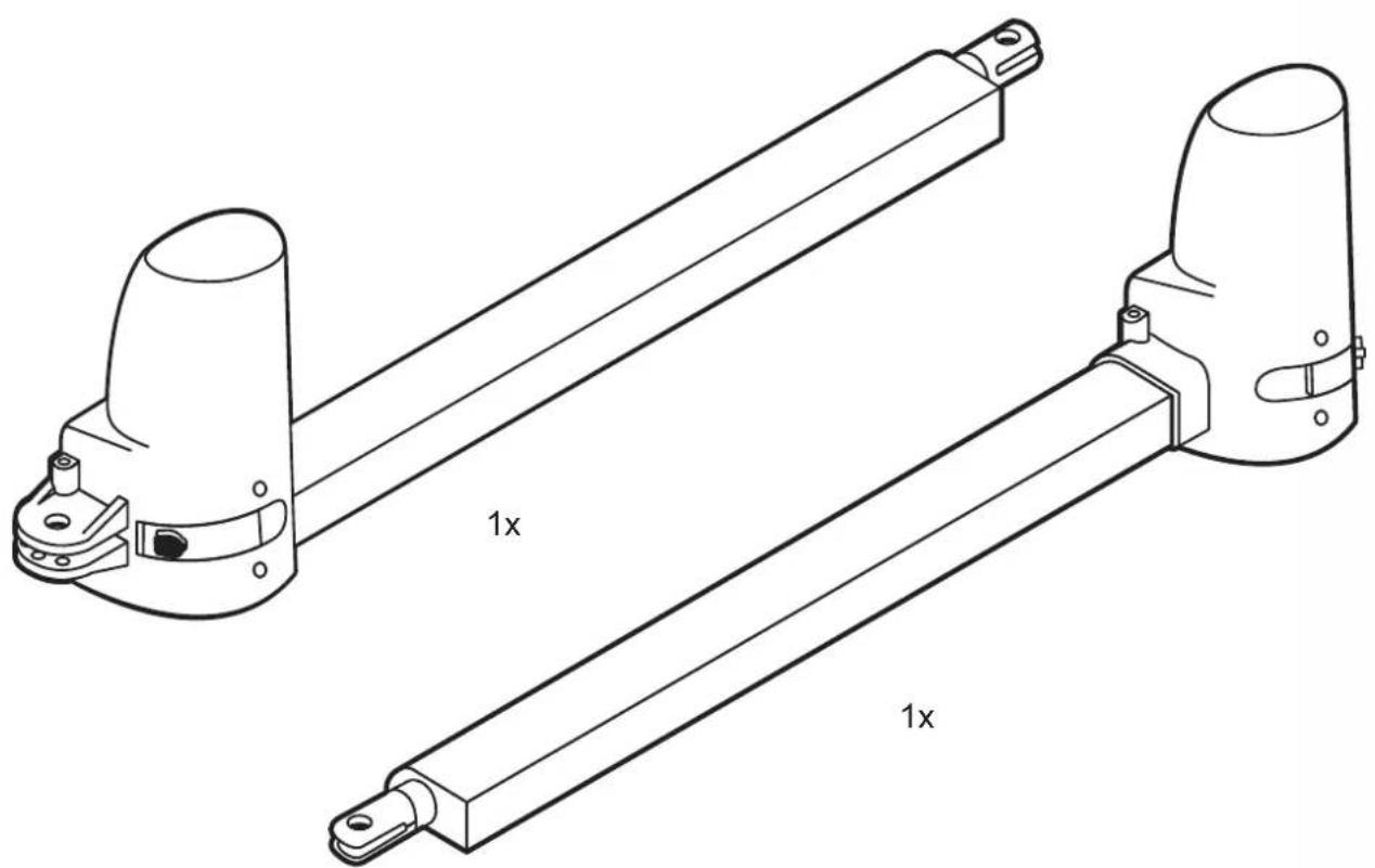
with your purchase of the Twin drive system from Schellenberg you have acquired a high-quality product. This product this product is intended for the actuation of double-leaf gates on residential premises. We hope that this product meets your expectations and thank you for the trust you have placed in us. If you have any questions regarding our products or the implementation options, please contact our Customer-Service:
Contact:
Important safety notes:
Electrical connections may only be performed by an authorized electrician. Such works pose a risk to health and life and therefore require special expertise.
Areas of application / use:
» On privately used double-leaf gates
The Schellenberg gate actuator systems are subject to a continuous improvement and further development process. We therefore reserve the right to implement changes due to technical progress and for the improvement of the products. Alterations and deviations from the illustrations as well as printing errors are reserved.
The performance of the actuator systems may be influenced by various factors such as specific on-site construction and conditions. No claims may arise based on the technical information as this may differ in individual cases.
General safety regulations / safety notes for the installer
CAUTION! To ensure the safety of persons, the instructions must be carefully read before proceeding with the installation of the product. An incorrect installation or faulty operation of the product can cause serious personal injury.
» The product and the packaging are not toys. Keep children away from them. There is a danger of injury and suffocation!
» The manual must be stored carefully, to properly enable a referencing in the future.
» This product has been exclusively developed and manufactured for the application purposes described in this document. Any other use that is not explicitly stated, could affect the integrity of the product and/or represent a source of danger.
» Schellenberg declines all liability for damage caused by an incorrect or improper use of the product.
» The mechanical parts must be conform with the requirements of the standards EN 12604 and EN 12605.
» Countries that do not belong to the European Union, are responsible for ensuring an appropriate level of safety according to national legal provisions beyond those defined by the above mentioned standards.
» Schellenberg shall not assume any liability in case of an unprofessional installation of the closing devices to be actuated, as well as for any deformation that may occur during the operation.
» The installation must be carried out in accordance with the standards EN 12453 and EN 12445. The force setting of the automatic module must be adapted to the gate. The actuator has a built-in safety device to prevent crushing injuries which consists of a torque control. In any case it is necessary to adjust the torque control to the gate appropriately. To minimize the risk of injury as far as possible, the force setting of the gate controller must be adapted to the gate as follows.
» After hitting an obstacle the actuator will reverse direction.
» Level 1 is the factory programmed the force setting.
» The safety devices (EN 12978 standard) allow the securing of potentially hazardous areas and protect against mechanical movement risks, such as crushing, dragging, and shearing injuries. During the programming of the force setting the safety shut-off will not be active.
» Prior to the execution of any job on the system, the electrical supply must be interrupted.
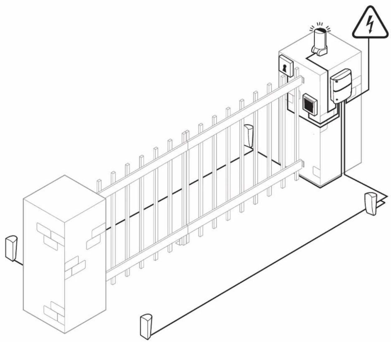
» For each system it is recommended to use at least one light signal as well as a warning sign which should be connected to the gate structure.
» Schellenberg disclaims all liability pertaining to the safety and trouble-free operation of the drive, if components are used on the system which were not supplied by Schellenberg.
» Only original parts from Schellenberg are authorized for use during maintenance.
» The components that are part of the drive system are not allowed to be altered in any way.
» The installer must hand over all information to the operator of the system which concern the manual operation of the system during emergencies as well as these installation instructions which were supplied with the product.
» Neither children nor adults are allowed to dwell in the immediate vicinity of the gate system during operation.
» The remote controls or other impulse transmitters must be kept out of reach of children to prevent accidental activation of the actuator.
» A passage between the gate leaves is only allowed when the gate is fully open.
» The operator shouldn't perform any repairs or directly intervene on the drive. If this should become necessary, only contact qualified technical personnel.
» Do not dispose of used batteries in the domestic trash! Appropriate collection-boxes are available in certain retailer localities.
» All procedures that are not expressly provided in these instructions are not permitted.
» The commissioning of the gate system is prohibited until it has been determined that the gate system complies with the provisions of all relevant applicable regulations and EU directives.
Assembly und operating instructions
To ensure the necessary security and the smooth operation of the actuators, the following preconditions must be checked:
» The installation of the electronic control unit housings must be performed with such a distance from the drives, that the motor cables will not require an extension in any case.
» For use in masonry or concrete posts, we recommend using chemical anchor bolts or anchor bolts which guarantee a stress-free mounting.
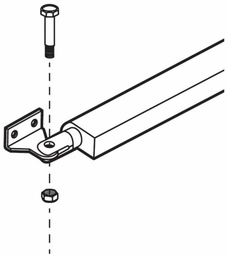
» The gate must be suitable for the actuator system. It must especially be ensured that it is sufficiently strong and rigid. For metal gate leafs we recommend establishing the connection to the actuators with screws. For wooden gates the fixing screws must be fully supported on the inside and outside with metal plates, since otherwise the screws could loosen over time.
» The dimensions and weights must match the specifications of the technical properties.
» Check for the smooth and uniform movement of the leafs and make sure that there is no friction or obstructions during the entire movement.
» Also ensure the perfect condition of the hinges.
» Mechanical end stops in the position “door closed” must be present.
» Remove the existing locks and blocking devices. It is recommended that any blacksmithing be carried out before mounting the actuators.
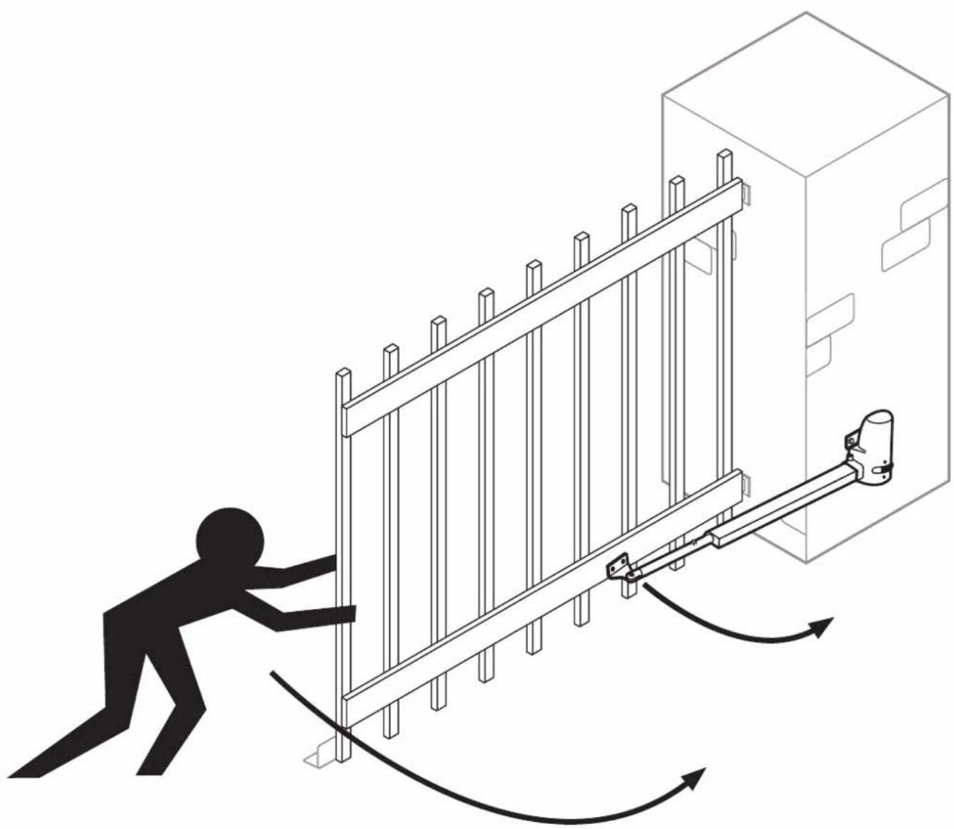
» Please observe that, depending on the opening angle, there must be an adequate space for the motion range of the gate.
After the installation
» The passage between the leafs is prohibited as long as they are in motion. Before passing through the gate leafs, the gate should be opened completely.
» The dwelling of persons between the leafs is strictly prohibited.
» The presence of people or the placement of objects in the immediate vicinity of the gate system is prohibited. This especially applies during the operation.
» The movement of the leafs should not be counteracted deliberately.
» Branches and shrubs may not interfere with the operation of the automatic gate system.
» The gate leafs should only be moved manually after the emergency-release has been actuated (unlocked).
» Prior to the execution of any intervention on the system, the electrical supply must be interrupted.
» In the event of operational malfunctions, the gate leafs must be unlocked to allow the access. It should be waited until qualified personnel is available for technical assistance.
» We recommend performing an operating capability test of the gate system, security devices and accessory equipment at least once every six months through qualified personnel.
» With the winter operation (page 19) you are able to ensure perfect operation during the winter months.
Warranty conditions
Dear customer,
thank you very much that you have decided to purchase a SCHELLENBERG product.
All SCHELLENBERG products are tested and subjected to the scrutiny of the SCHELLENBERG quality assurance.
We therefore guarantee that our products are free from material and manufacturing defects.
Excluded from the warranty are damages that are caused by:
» use-related, normal wear
» improper installation, connection, operation or treatment
» acts of God or other external influences
» improper maintenance or repair by third parties
» technical alterations by third parties
In case of a warranty case we will repair the product at our discretion, or exchange it for an equivalent SCHELLENBERG product. Replacement or repair of the unit will not extend the warranty period. This manufacturer's warranty is without prejudice to any statutory warranty claims which you as a consumer may have against the seller under the applicable law, including any special protection provisions for consumers. The warranty neither excludes nor limits the statutory warranty. A condition for a warranty claim processing is the presentation of a copy of the original sales receipt. When you return a product back to us, please include a copy of the original sales receipt and a description of the defect. The warranty period for the Twin 300 drive is 24 months from the date of purchase. Please contact our Consumer Service Department regarding any warranty claims, requests for spare parts or questions regarding the proper installation of your product. The SCHELLENBERG team is always happy to be able to personally consult you.
The SCHELLENBERG team is always happy to be able to personally consult you.
Unit shipment to:
We hope you enjoy the product you acquired to the fullest.
Your SCHELLENBERG team
EC DECLARATION OF CONFORMITY
(in the sense of the EC Machinery Directive 2006/42/EC, annex II, part 1 A)
We herewith declare,
Manufacturer:
that the product listed below:
Swing gate drive TWIN 300
corresponds to the fundamental safety and health requirements of the following EC/EU directives/regulations, through its design and construction in the version marketed by us:
EU Electromagnetic Compatibility Directive 2014/30/EC
EU Directive RED 2014/53/EC
EC Machinery Directive 2006/42/EC
EU Directive RoHS 2011/65/EC
EC Directive WEEE 2012/19/EC"
Utilized as well as applied standards and specifications:
EN 301489-1, EN 301489-3, EN 300220-1, EN 300220-2, EN 60335-1, EN 60335-2, EN 62233, EN 12453, EN 12445
Note: The commissioning of the final product or in combination is prohibited by Alfred Schellenberg GmbH until the conformity of the end product or a combination of this swing gate drive and gate has been established on the basis of the respectively applicable standards, specifications or guidelines. In case of doubt, a professional installer should be consulted for this.
The Managing Director of the above mentioned manufacturer is the authorised entity for the compilation of the technical documentation.
Siegen, May 20, 2016
Sascha Schellenberg
Managing Director
"Confirmation of conformity through the assembly specialist company"
Gate manufacturer / type:
Serial number of the components:
Company: ____ Date: ____ Signature / function: ____
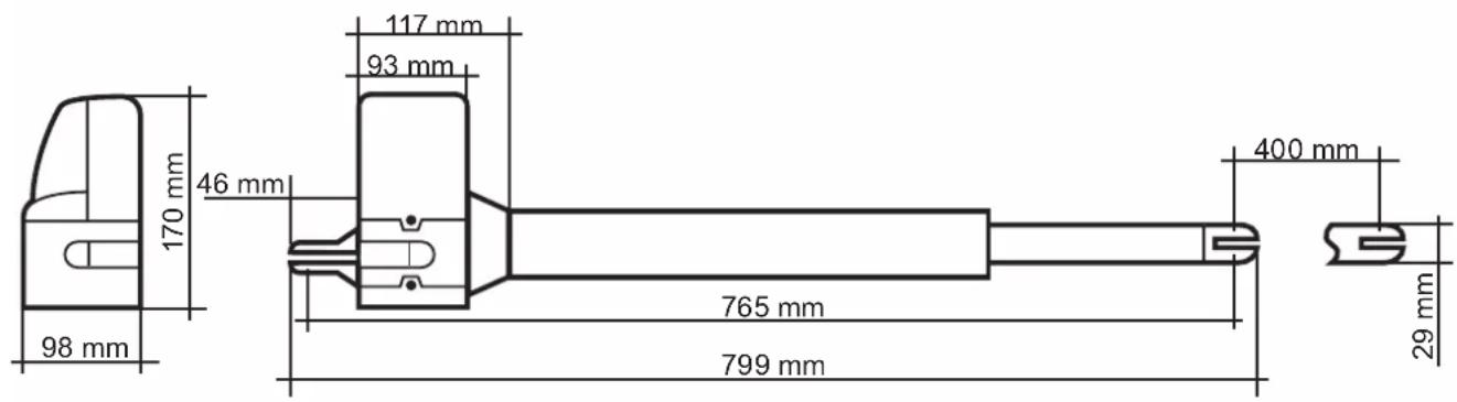
TECHNICHAL DATA
| Voltage Input 220 V-240 V | AC / 50 HzOutput 24 V DC | |
| Motor Motor voltage 24 V | DCPerformance 50 W | |
| Drive arm Linear spindle drive | 2 QuantitySpeed without load 25 mm / sec.Stroke 400 mmMax. traction 2 x 2000 NMax. gate weight 2 x 200 KgMax. gate width * 2 x 2,5 mMin. gate width 2 x 1,2 mTemperature range -20°C up to +50°Coperating cyclesMax. opening angleEmergency release | 15.000>120°Key |
| Control | Soft start/stopAutomatic force settingGate open positionGate closed position | YesYes90° -> 120° depending on the installation situation external mechanical stopper |
| Radio | frequencyRange outdoors approx. | 433,92 MHz40 m |
| Dimensions | PackagingControlDriveDrive retractedDrive retracted | 900 x 310 x 245 mm295 x 195 x mm799 x 98 x 170 mm765 mm1165 mm |
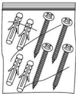
| Accessories (optional) | Art. No.60030 / 6003125101 / 2510325102 / 2510420058 / 2005760060 / 6006160999 / 6099760859 / 6086060853 / 6085260854 / 6085760855 / 6085860856 / 60861 | |
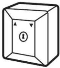
| Light barrierKey switch, surface-mountedKey switch, flush-mountedRadio coding switchInner keySmartphone garage door openerWireless in-car transmitterHand-held wireless remote control DRIVEHand-held wireless remote control STANDARDHand-held wireless remote control PLUSHand-held wireless remote control PREMIUM | ||
| * without wind load |
DIMENSIONS
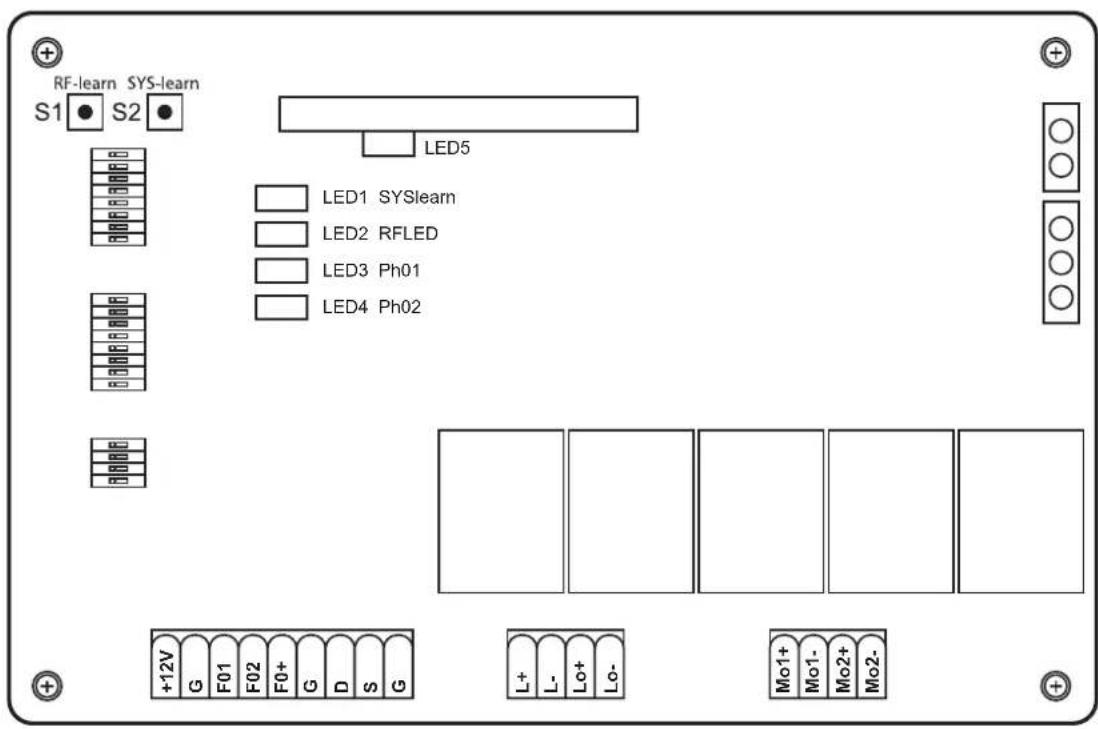
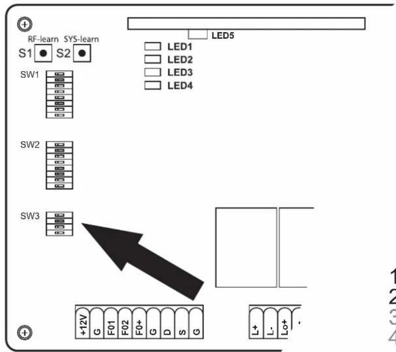
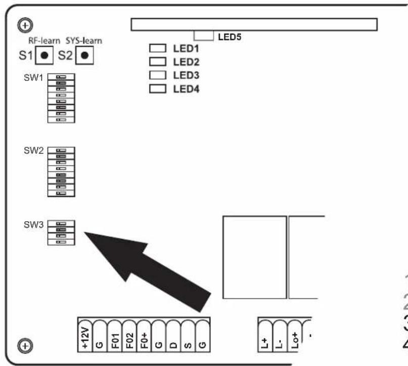
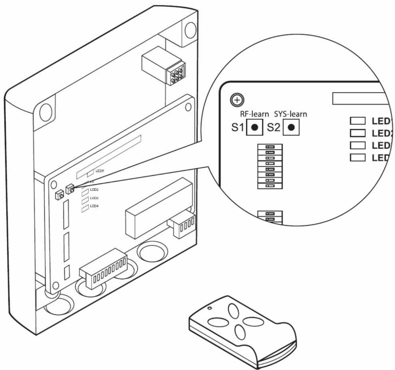
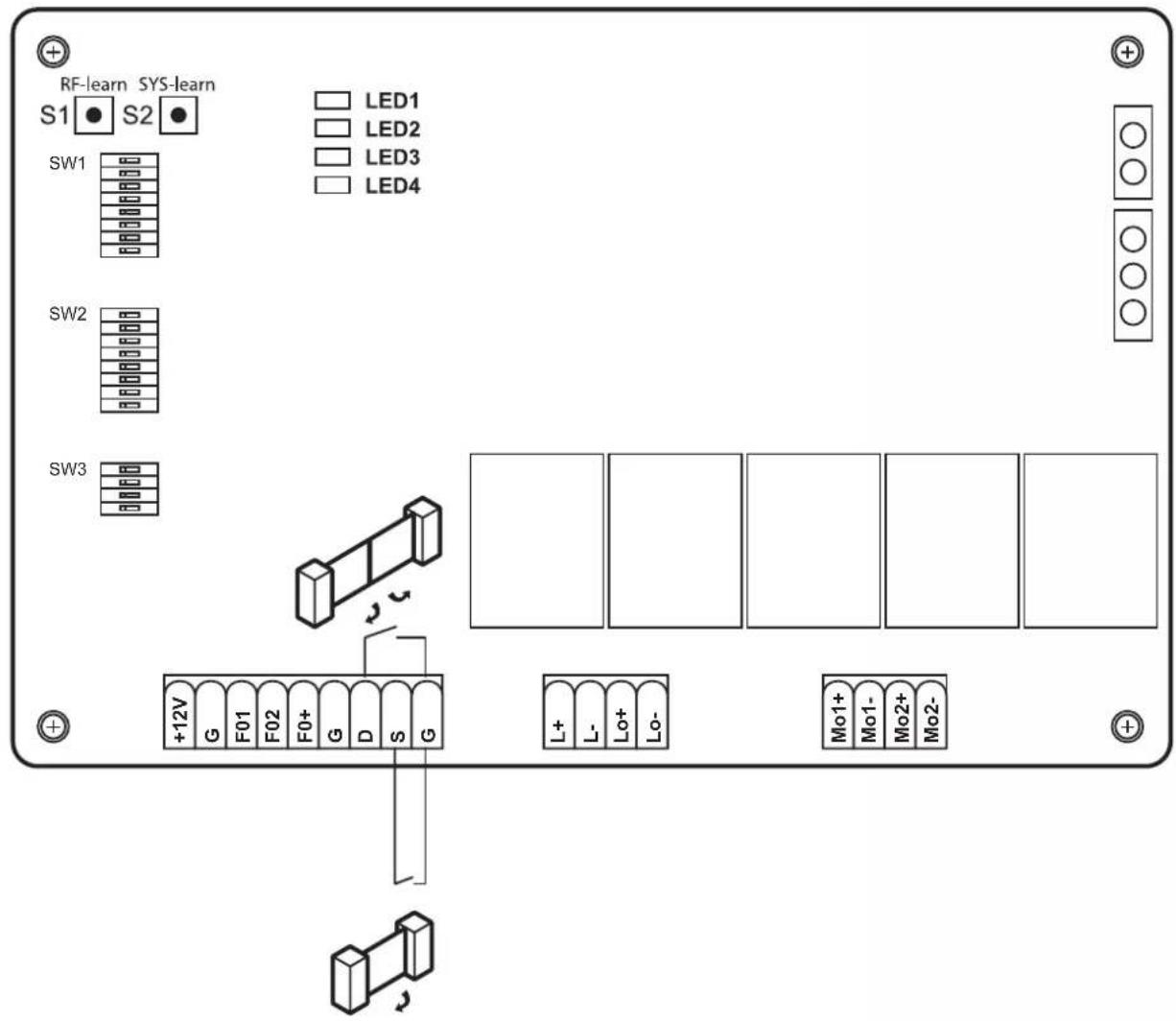
A LEGEND AND EXPLANATION OF THE SWITCHES FOR THE PROGRAMMING

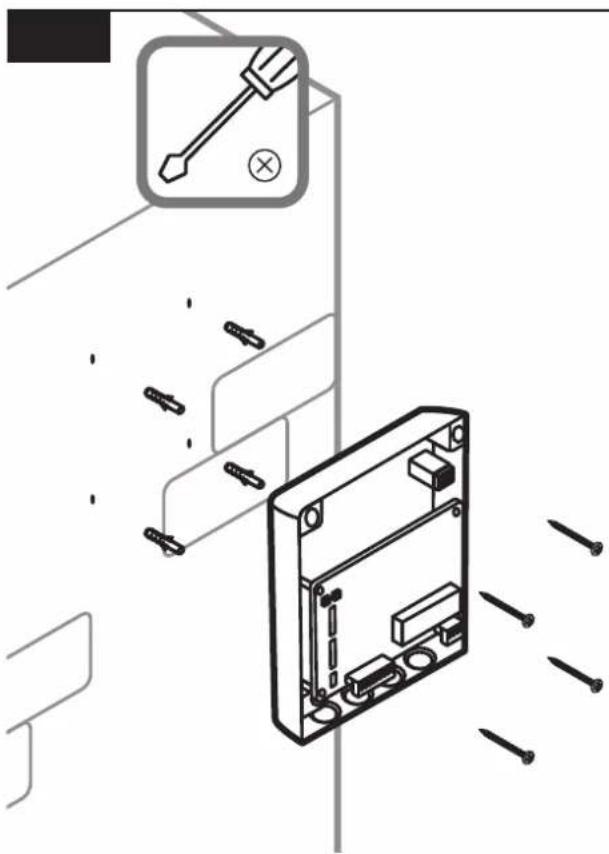
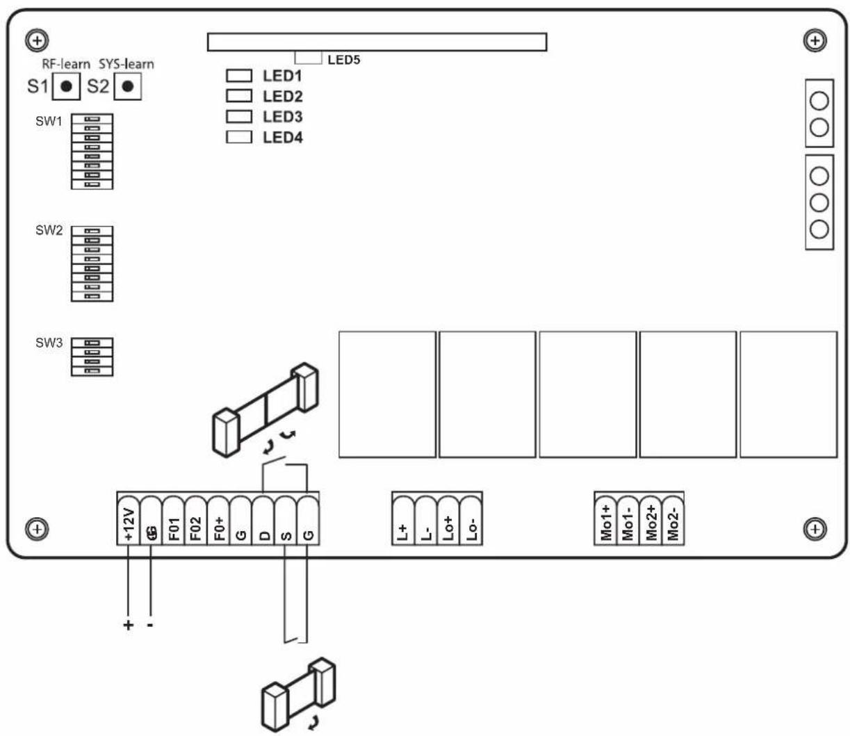
All settings of the dip switches must be performed prior to the commissioning and before power is supplied to the controller, in order to ensure a proper functionality of the settings.
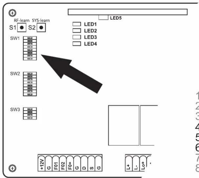
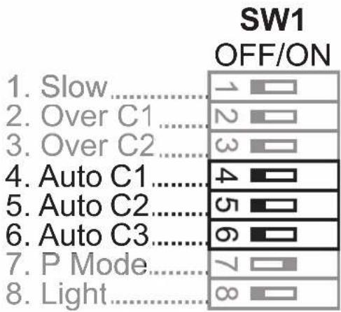
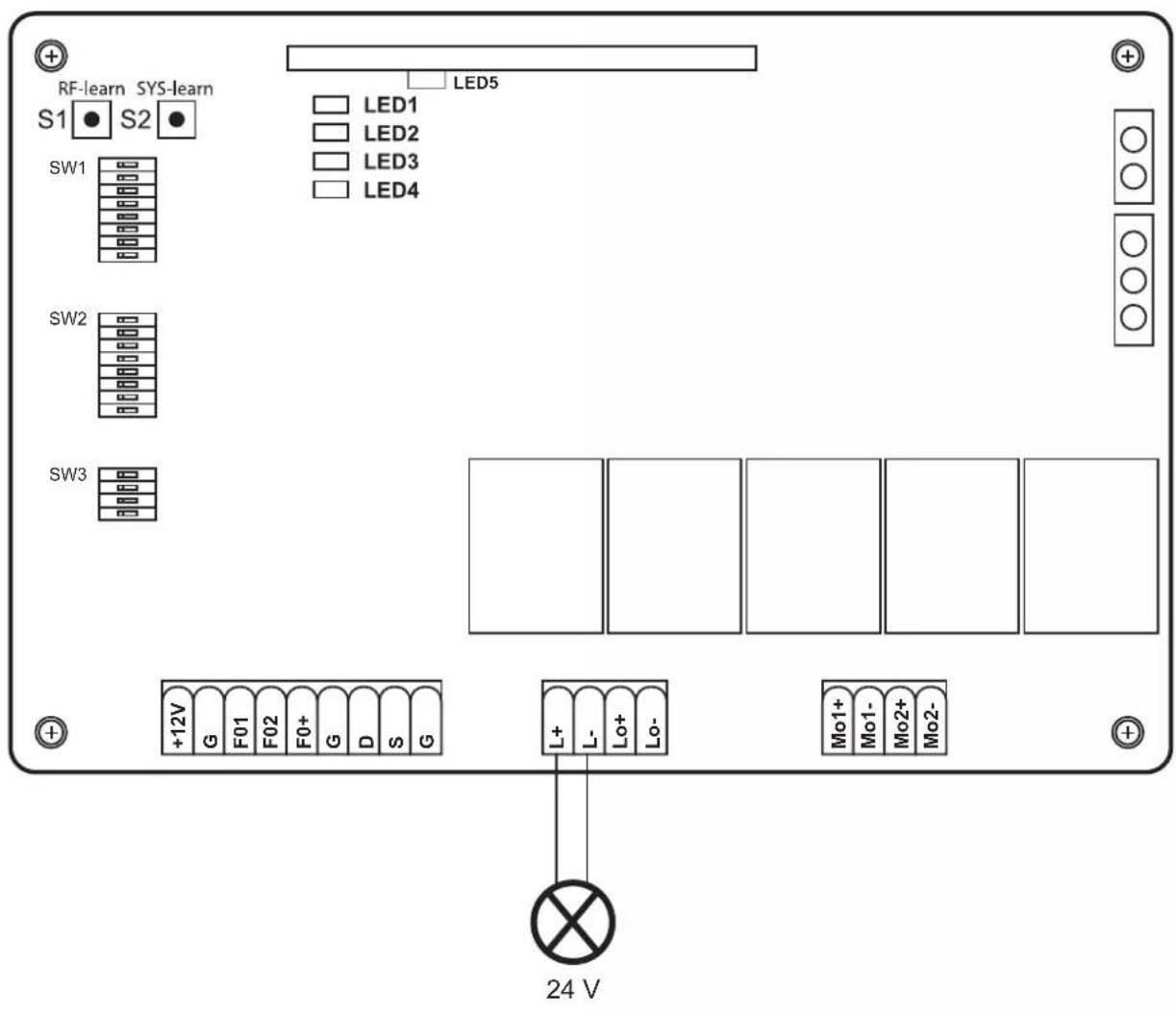
SW1:
1. Slow: Optional soft-start and soft-stop setting
ON: The motors move at a continuous speed during the opening and closing up to the end positions.
OFF: The motors reduce their speed during the closing and opening before they reach the end positions (protects the gearbox).
2.-3. Over\_C1 + Over\_C2: Optional force setting
The factory-set forces (value 1) are designed to enable a smooth operation of standard gates (which are intended for use with this drive). The forces exerted in the factory default setting should fundamentally be sufficient to fully open and close the gate to be operated. In the factory default setting, the drive complies with the legal or relevant standards (for example, EN 12455, EN 12453; EN 60335-2-95) pertaining to the requirements for the operating forces and therefore the maximum permissible force limits. The forces to be exerted by the drive can be increased if required, through the procedure described below (values 2-4).
NOTE
This could be required, for example, if the „gate open“ or “gate closed” end stops are not reached with the factory default setting (value 1). In this case, the setting for the maximum force must be increased gradually, until the respective end stop is reached.
Winter operation:
We recommend increasing the force level during the winter months if the „door open“ or „door closed“ end stop is not reached with the factory default setting (value 1). In this case, the setting for the maximum force must be increased gradually, until the respective end stop is reached.
CAUTION
An increased setting which deviates the factory default setting (value 1) can lead to serious personal injury and even a mortal danger, as well as severe property damage!
An increased force value which deviates from the factory default setting (value 1) increases the forces exerted onto the gate during the opening and closing motion. If a factory default setting is changed, there is a danger of serious personal injury up to mortal danger through a possible jamming or crushing of persons or items within in the gate area, as well as the risk of damage to property, since a force setting which deviates from the factory default setting can possibly lead to an exceeding of the specified maximum permissible force limits. Therefore, the following shall apply:
After each force setting change (values 2-4) which deviates from the factory default setting (value 1), the full compliance with the statutory or relevant standards regarding the force limit values must be checked, approved and documented by a competent person, in order to exclude the indicated dangers for life and limb.
More information is available on page 299
4.-6. Auto\_C1 - Auto\_C3: Optional automatic closing function
The door closes independently after the pre-set time, once the end position „open“ has been approached. For your own safety, the automatic closing function may only be enabled, if the system is operated in conjunction with an additional safety device, e.g. a light barrier.
More information is available on page 300
7. P\_Mode: Optional customization of the pedestrian function
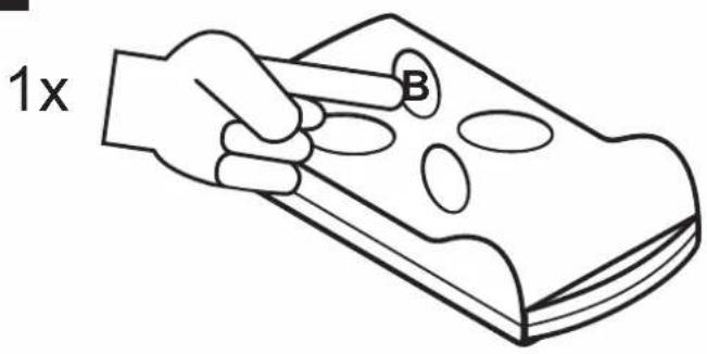
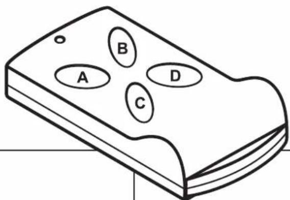
ON: Press the button B on the hand-held wireless remote control to only open one door leaf (45° opening angle).
OFF: Pedestrian function is disabled. The drive opens and closes completely.
8. Light: Optional signal lamp setting
A 24 V signal lamp can be connected optionally.
ON: The signal lamp will flash for 3 seconds before the gate is set in motion again, and during the complete opening and closing cycle
OFF: The signal lamp will flash during the opening and closing cycle
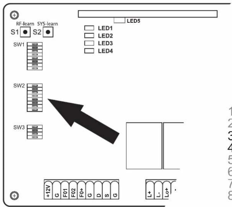
SW2:
3.-4. Delay\_2: Optional adjustment of the opening and closing delay
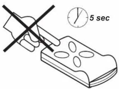
The opening and closing delay of the 2- leaf drives can be set between 2-6 seconds.
More information is available on page 301
6. D-speed: Optional adjustment of speed in the range of the soft-start / soft-stop
ON: The speed is reduced to 70% of the standard gate speed
OFF: The speed is reduced to 50% of the standard gate speed
7. O\_speed: Optional adjustment of the factory-set speed (beyond the soft-start / soft-stop range)
ON: 100%
OFF: The speed is reduced to 70% of the standard gate speed
8. D/S\_Set: Setting of the 1-leaf or 2-leaf operation
ON: 2-leaf operation (also for the teach-in process)
OFF: 1-leaf operation (also for the teach-in process)
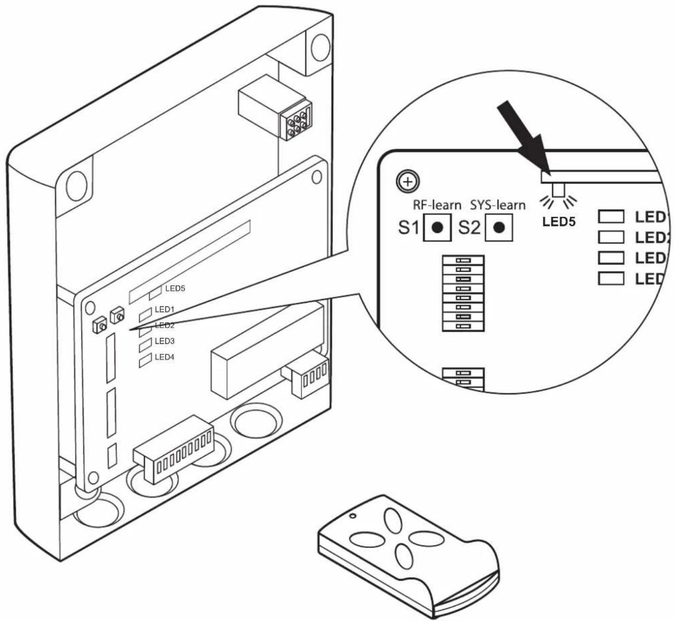
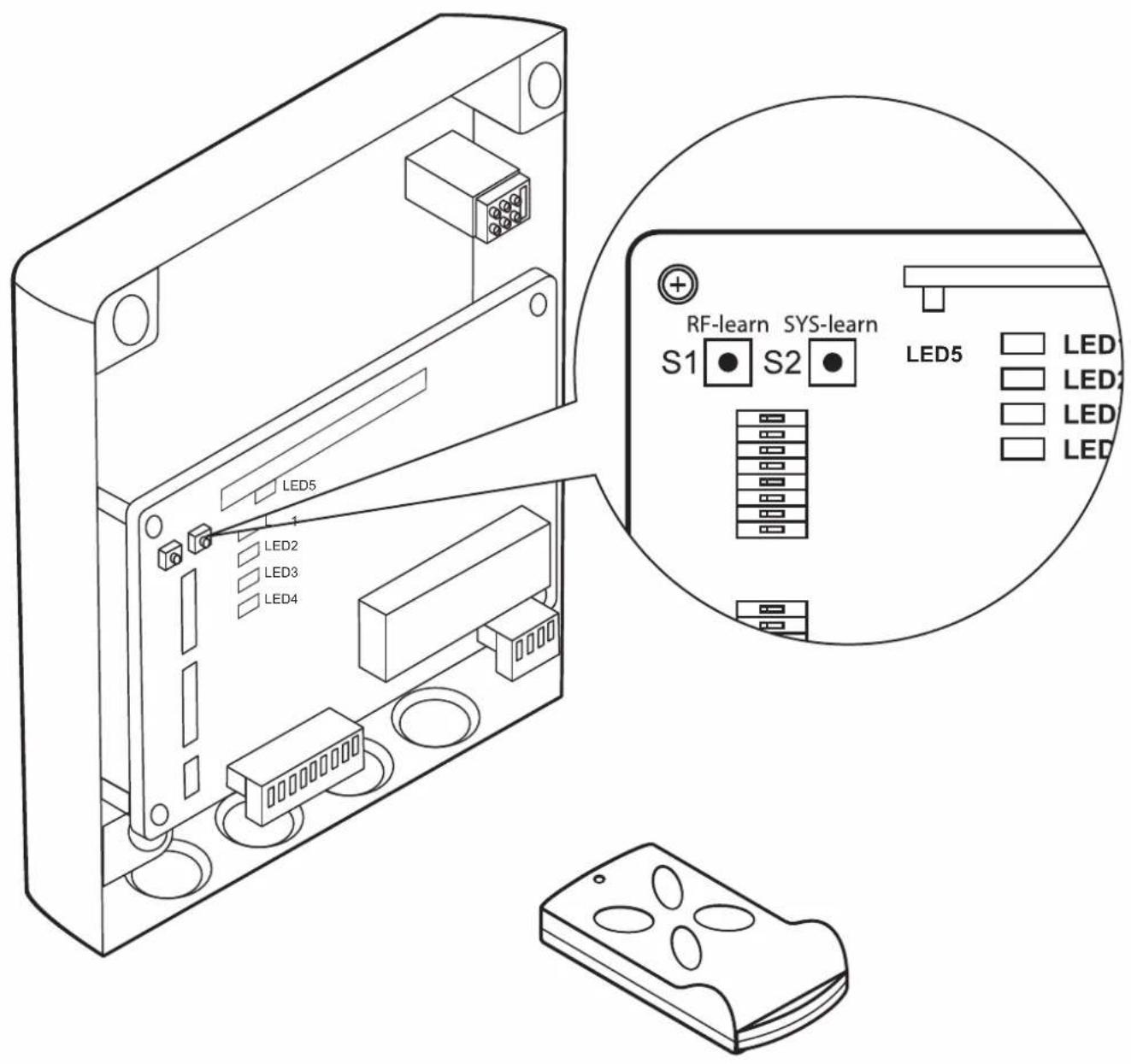
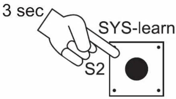
S1-S2:
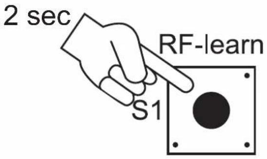
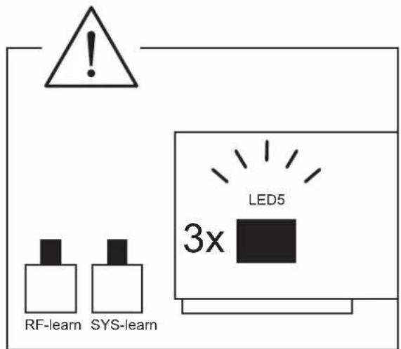
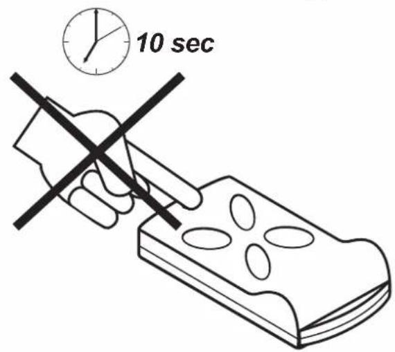
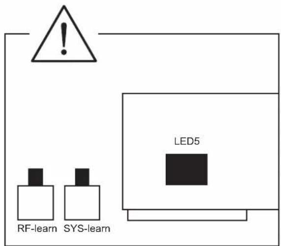
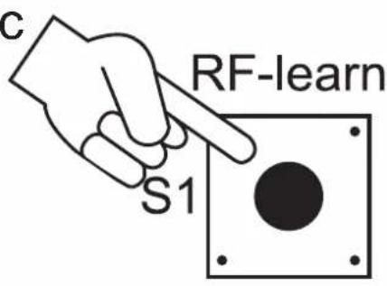
RF-learn (1): Hand-held transmitter teach-in - for a single gate or two gates
More information is available on page 302
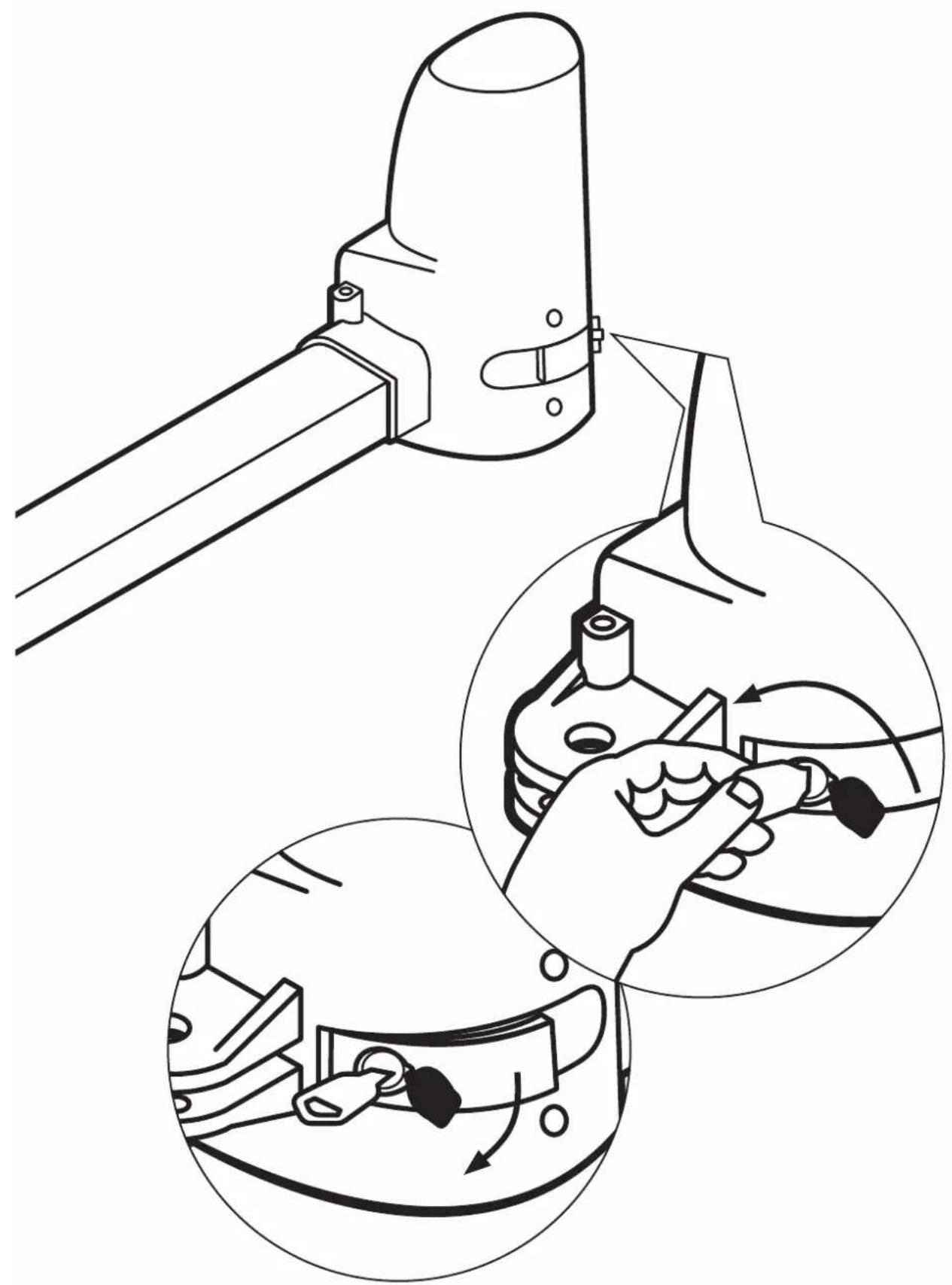
SYS-learn: End-point adjustment
More information is available on page 304
RF-learn (2): Delete hand-held transmitter
More information is available on page 310
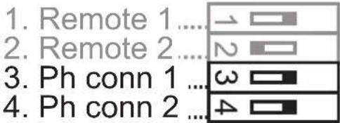
SW3:
1.-2. Remote\_1 - Remote\_2: Optional adjustment of the hand-held transmitter function 4 channel
More information is available on page 308
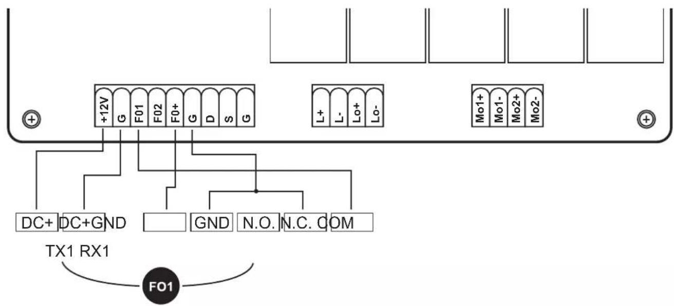
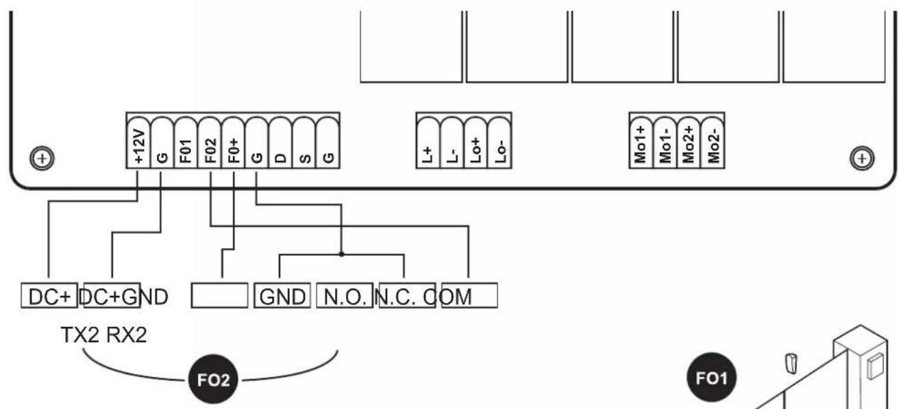
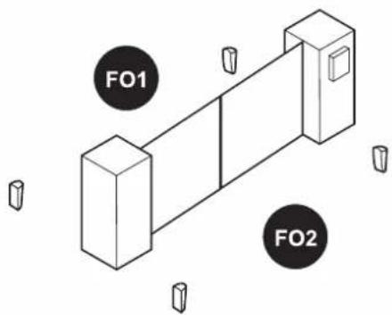
3.-4. Ph\_conn1 - Ph\_conn2: Optional light barrier setting
More information is available on page 309
Factory default setting
Prior to the initial commissioning the controller is pre-set as follows.
| Function Conditivon | |
| SW1 | |
| 1. Soft-start and soft-stop enabled | |
| 2.-3. Force adjustment Force level 1 | |
| 4.-6. Automatic closing function disabled | |
| 7. Pedestrian function Opening angle 45° | |
| 8. Signal lamp function The signal lamp will flash during the opening and closing cycle | |
| SW2 | |
| 3.-4. Opening and closing delay Opening delay of the 2nd gate leaf by 2 secondsClosing delay of the 2nd gate leaf by 3 seconds | |
| 6. Speed in the range of the soft-start / soft-stop 70% of the standard gate speed | |
| 7. Default gate speed (beyond the soft-start / soft-stop range) | 100% of the standard gate speed |
| 8. Setting of the 1-leaf or 2-leaf operation 2-leaf operation | |
| SW3 | |
| 1.-2. Hand-held transmitter function | Button A: double-sided opening, button B: single-sided opening disabled |
| 3.-4. Light barrier function disabled | |
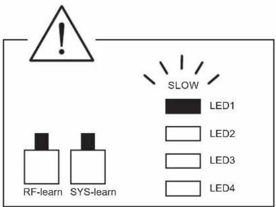
LED LEGEND
LED1: LED1 lights up continuously if the system is not fully taught-in. LED1 flashes once when the system is completely taught-in (for 1 leaf systems). LED1 flashes twice when the system is completely taught-in (for 2 leaf systems).
LED2: if the hand-held transmitter is activated, or the key switch or button is activated, then LED2 will be lit.
LED3: the LED3 lights up as soon as the first light barrier is activated.
LED4: the LED4 lights up as soon as the second light barrier is activated.
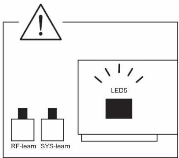
LED5: the LED 5 lights up as soon as a hand-held transmitter signal has been received.

SOMMAIRE
DÉCLARATION DE CONFORMITÉ CE
(dans le sens de la directive Machines CE 2006/42/CE, annexe II, section 1 A)
Directive CE Machines 2006/42/CE
Directive UE RoHS 2011/65/UE
Directive CE DEEE 2012/19/CE
INHOUD
Montage en bedieningshandleiding 32
Sascha Schellenberg
Manager

SPIS TREŚCI
DEKLARACJA ZGODNOŚCI WE
INDICE
Sascha Schellenberg
ÍNDICE
Sascha Schellenberg
Director gerente
ÍNDICE
DEKLARACJA ZGODNOŚCI WE
Sascha Schellenberg
Director
RF-learn (2): Eliminar o emissor manual

OBSAH
OBSAH
Sascha Schellenberg
Konatel'
Potvrdenie konformity odbornou montážnou firmou
Výrobca brány/typ:
TARTALOM
SADRŽAJ
Ugradnja i upute za uporabu ....104
Izjava proizvođača o sukladnosti proizvoda u skladu s direktivama EZ-a ....107
Tehnički podaci ....108
Dimenzije 108
A Legenda i objašnjenje sklopki za programiranje ....109
B Ugradnja....282
C Opće opcije postavki i ručnog odašiljača moraju se programirati....298
- Opcija postavke sile 299
- Opcija automatske funkcije zatvaranja ....300
- Opcija prilagođavanja odgode otvaranja i zatvaranja ....301
- Programiranje daljinskog upravljača ....302
- Namještanje krajnje točke ....304
- Opcija prilagođavanja funkcije ručnog odašiljača ....308
- Opcija namještanja svjetlosne prepreke ....309
- Brisanje daljinskog upravljača ....310
D Pribor koji je opcija ....312
E Sheme priključivanja opcija proširenja ....314
UGRADNJA I UPUTE ZA UPORABU
Cijenjeni korisnic,
Sascha Schellenberg
Direktor
VSEBINA
Montaža in navodila za uporabo ....113
EU izjava o skladnosti ....116
CUPRINS
Sascha Schellenberg
Director

СЪДЪРЖАНИЕ
Sascha Schellenberg
Управител:
ПЕРИЕХОМЕНА
Sascha Schellenberg
Διευθυντής

İÇİNDEKİLER
СОДЕРЖАНИЕ
Sascha Schellenberg

3MICT
TURINYS
LT
SATURS
SISUKORD
Olulised ohutusjuhised:

INNEHÄLLSFÖRTECKNING
Skicka in enheten till:
Ert SCHELLENBERG-team
INTYG OM ÖVERENSSTÄMMELSE MED EU-DIREKTIV
Sascha Schellenberg
A BESKRIVNING OCH FÖRKLARING AV KNAPPARNA FÖR PROGRAMMERINGEN

INDHOLD
Sascha Schellenberg
Direktør

INNHOLD
Sascha Schellenberg
Daglig leder
Samsvarsbekreftelse framonteringsbedriften
Portprodusent / type:
SISÄLTÖ
PËRMBAJTJA
SADRŽAJ
Upute za montažu i uporabu....248
UPUTE ZA MONTAŽU I UPORABU
Poštovani kupče,
Kupovinom Twin pogona kuće Schellenberg, odlučili ste se za kvalitetan proizvod. Ovaj je proizvod pogodan za pogon krilnih vrata ograda privatnih domaćinstava. Nadamo se da ćemo ovim proizvodom ispuniti Vaša očekivanja i zahvaljujemo se na iskazanom povjerenju. U slučaju pitanja o našim proizvodima ili mogućnostima njihove primjene, molimo Vas obratite se našoj službi za korisnike:
Kontakt:
САДРЖАЈ
EFNI
Uppsetningar- og notkunarleiðbeiningar 266
EB-samræmisyfirlýsing 269
Tæknilýsing....270
Stærðir....270
natural_image
Row of eight tool icons including a screwdriver, wrench, ruler, pencil, screwdriver, and clamp (no text or labels)
natural_image
Technical line drawing of two mechanical components with 1x scaling labels (no text or symbols beyond '1x')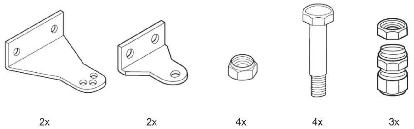
natural_image
Simple line drawing of a stylized human figure with a circular head, no text or symbols present2x2
natural_image
Isometric line drawing of a rectangular object with four circular indentations on its surface (no text or symbols)2x
natural_image
Illustration of multiple screw fasteners with different thread configurations (no text or symbols)1x
1x
natural_image
Simple line drawing of a rope tied with two knots (no text or symbols)1x2m
natural_image
Illustration of a rope tied with a string, no text or symbols present1x7m
natural_image
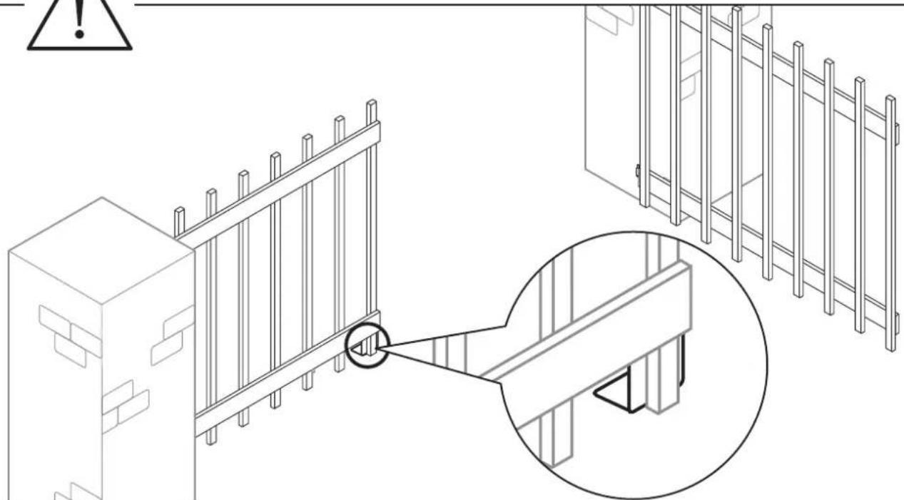
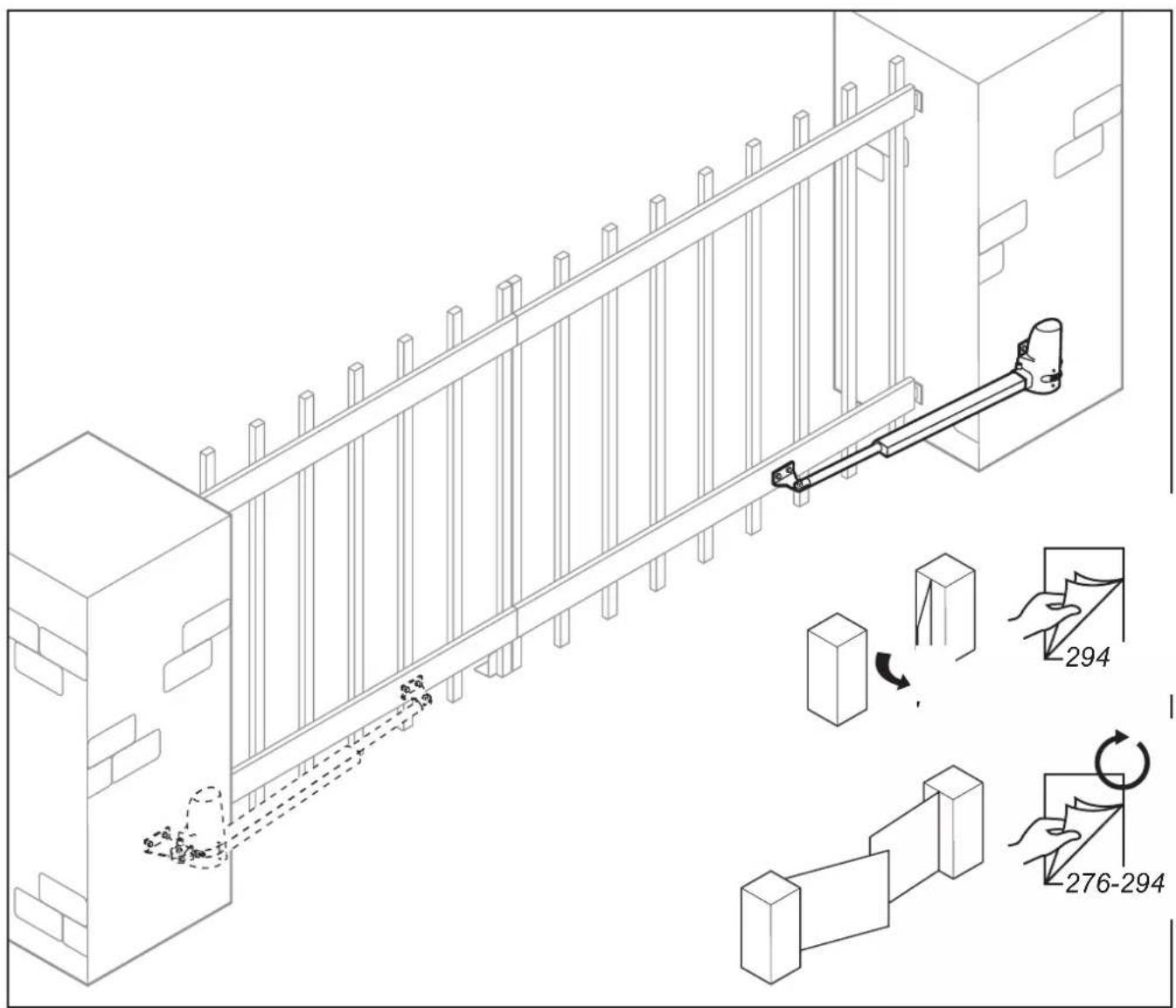
Isometric line drawing of a fence structure with an inset close-up showing a detail (no text or symbols)GB To ensure trouble-free operation, these measures are strictly adhered to.
To ensure a trouble-free operation, these dimensions must absolutely be maintained. Please observe that, depending on the opening angle, there must be an adequate space for the motion range of the gate. If there is an obstacle within the travel range, a door stop must be provided in order to reduce the opening angle.
natural_image
Technical illustration showing a mechanical clamp and two circular insets depicting hand tool manipulation (no text or symbols)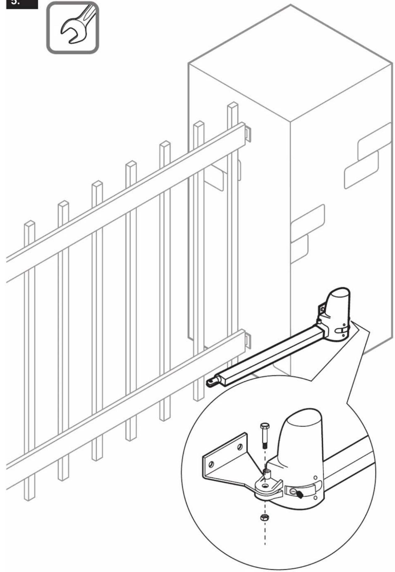
natural_image
Technical line drawing of a mechanical assembly with a bracket and mounting bracket, plus an inset close-up of a mechanical clamp (no text or symbols)
natural_image
Technical line drawing of a mechanical bracket assembly with a bolt and nut, no text or symbols present7.
natural_image
Illustration of a person pulling a wall-mounted lock mechanism with directional arrows indicating motion (no text or symbols)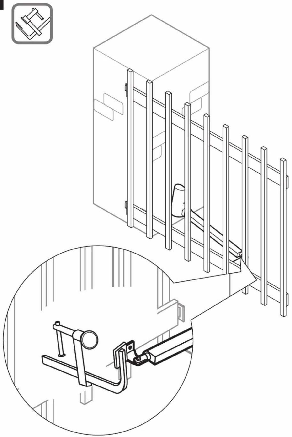
natural_image
Technical line drawing of a cabinet with ladder and support structure, plus a magnified inset showing the same components (no text or symbols)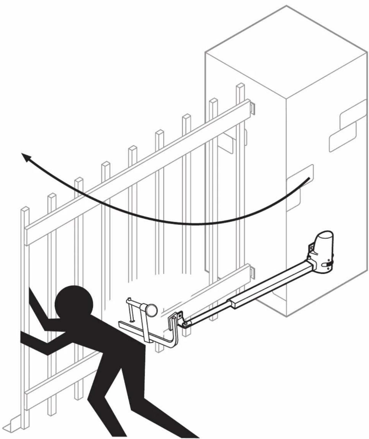
natural_image
Illustration of a person using a mechanical lever system to lift a wall-mounted device, with no visible text or symbols.10.
natural_image
Technical illustration of a mechanical device with three circular insets showing hand operating components (no text or symbols)
natural_image
Technical line drawing of a mechanical assembly with a bracket and tool, showing a 2x magnified view (no text or symbols)SCHELLENBERG
SCHELLENBERG

natural_image
Two simple line drawings: a ruler and a pencil, both enclosed in rounded square frames (no text or symbols)
16.1

flowchart
graph TD
    A["Start"] --> B{Decision}
    B -->|Yes| C["Process 1"]
    B -->|No| D["Process 2"]
    C --> E["End"]
    D --> E
    style A fill:#f9f,stroke:#333
    style E fill:#bbf,stroke:#333
natural_image
Technical illustration of a computer case with screwdriver and screw rod assembly (no text or symbols)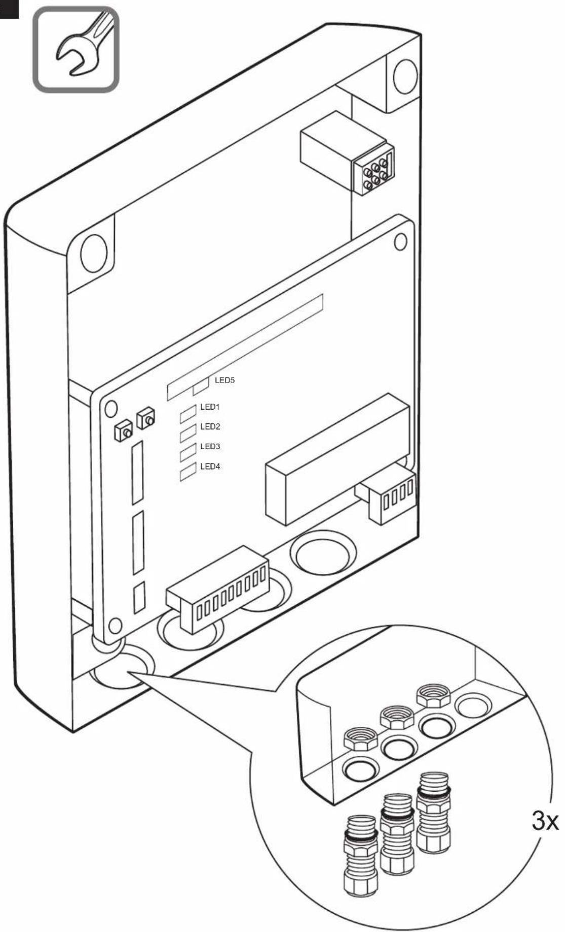
C
DE Werkseinstellung
GB Factory default setting
FR Réglage usine
NL Fabrieksinstelling
PL Ustawienie fabryczne
IT Impostazione di fabbrica
ES Ajustes de fábrica
PT Ajuste de fábrica
© Tovární nastavení
SK Výrobné nastavenie
HU Gyári beállítások
HR Tvornička postavka
SI Tovarniške nastavitve
RO Setare din fabricatie
BG Фабрична настройка
GR Εργοστασιακή
ρύθμιση
TR Fabrika ayari
RU Заводская настройка
UA Заводська настройка
LT Gamyklinis nustatymas
LV Rūpnīcas iestatījums
EE Tehaseseadistus
SE Fabriksinställning
DK Fabriksindstilling
NO Fabrikkinnstillinger
FI Tehdasasetus
AL Cilësimi në fabrikë
BA Tvorničke postavke
XS Фабричке поставке
IS Verksmiðjustilling
C1
SW1
OFF/ON
- Slow......
- Over C1.....
- Over C2.....
- Auto C1.....
- Auto C2......
- Auto C3.....
- P Mode.....
- Light......
| 2. Over C1 3. Over | C2 |  |
| OFF N ON | OFF ω ON | 1 |
| OFF N ON | OFF ω ON | 2 |
| OFF N ON | OFF ω ON | 3 |
| OFF N ON | OFF ω ON | 4 |
C2
bar
SW1 OFF/ON | Category | Value | |---|---| | 1. Slow.... | 1 | | 2. Over C1.... | 2 | | 3. Over C2.... | 3 | | 4. Auto C1.... | 4 | | 5. Auto C2.... | 5 | | 6. Auto C3.... | 6 | | 7. P Mode.... | 7 | | 8. Light.... | 8 || 4. Auto C1 5. Auto C2 6. Auto C3 |  | ||
| OFF ▲ □ ON | OFF ▶ □ ON | OFF ◎ □ ON | OFF |
| OFF ▲ □ ON | OFF ▶ □ ON | OFF ◎ □ ON | 3 sec |
| OFF ▲ □ ON | OFF ▶ □ ON | OFF ◎ □ ON | 10 sec |
| OFF ▲ □ ON | OFF ▶ □ ON | OFF ◎ □ ON | 20 sec |
| OFF ▲ □ ON | OFF ▶ □ ON | OFF ◎ □ ON | 40 sec |
| OFF ▲ □ ON | OFF ▶ □ ON | OFF ◎ □ ON | 60 sec |
| OFF ▲ □ ON | OFF ▶ □ ON | OFF ◎ □ ON | 120 sec |
| OFF ▲ □ ON | OFF ▶ □ ON | OFF ◎ □ ON | 360 sec |
C3
SW 2
OFF/ON
- Photo 1.....
- Photo 2.....
- Delay 1 ...... ω □
- Delay 2.....
- Latch.....
- D speed .....
- O speed.....
- D/S Set .....
| 3. Delay 1 4. Delay 2 |  | 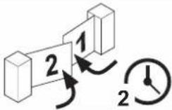 | ||
| OFF ON | OFF ON | 3 sec2 sec | ||
| OFF ON | OFF ON | 4 sec2 sec | ||
| OFF ON | OFF ON | 5 sec3 sec | ||
| OFF ON | OFF ON | 6 sec3 sec | ||
C4

C5
natural_image
Line drawing of two 3D geometric shapes: a cube and an open door, connected by a line (no text or symbols)
natural_image
Simple line drawing of a hand holding a sheet of paper next to a device with three ovals (no text or symbols)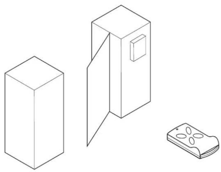
natural_image
Line drawings of three household appliances: a box, a door with a vent, and a remote control unit (no text or symbols)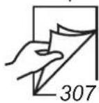
1.

2.
1x
natural_image
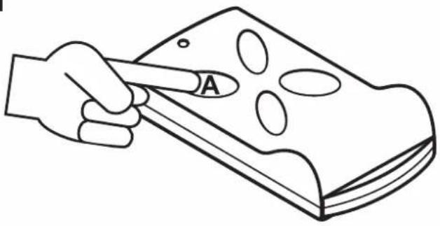
Line drawing of a hand holding a rectangular object with circular indentations, labeled 'A' (no text or symbols on the object itself)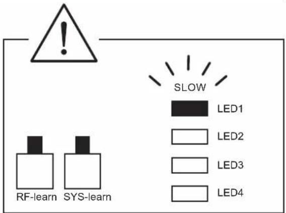
flowchart
graph TD
    A["Step 1: L-shaped block"] --> B["Step 2: Reordering block"]
    B --> C["Step 3: Reordering block"]
    C --> D["Step 4: Reordering block"]


1
natural_image
Diagram showing three 3D geometric shapes with rotation arrows, no text or symbols present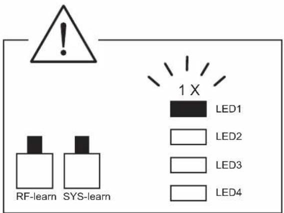
C6
SW 3
OFF/ON
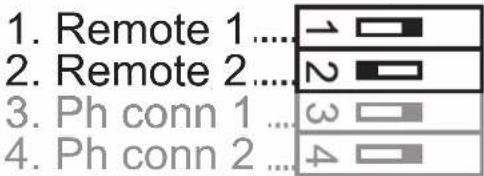
| 1. Remote 1 2. Remote 2 |  | 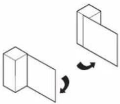 | |
| OFF → ON | OFF N ON | A | B |
| OFF → ON | OFF N ON | B | A |
| OFF → ON | OFF N ON | C | D |
| OFF → ON | OFF N ON | D | C |
C7
SW 3
OFF/ON
| 3. Ph conn1 | 4. Ph conn2 | |
| FO1 (RX1+TX1) | OFF ON | OFF ON |
| FO2 (RX2+TX2) | OFF ON | OFF ON |
| FO1+FO2 | OFF ON | OFF ON |
| OFF | OFF ON | OFF ON |
C8
1.
10 sec


10sec

LED5
natural_image
Simple line drawing of a 3D rectangular prism adjacent to a tilted rectangular prism (no text or symbols)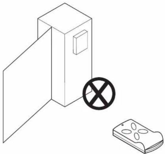
natural_image
Simple line drawing of a cabinet with an open door and a prohibition symbol (no text or labels)D
natural_image
Isometric line drawing of an electrical enclosure with warning sign and safety symbols (no text labels)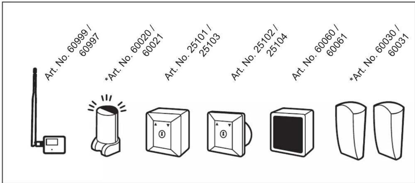
* Kommisionsartikel
E
natural_image
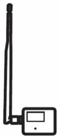
Simple line drawing of a wireless device with antenna and display (no text or symbols)Art. No. 60999 / 60997
natural_image
Simple line drawing of a warning light with no text or symbolsArt. No. 60020 / 60021
natural_image
Simple line drawing of a 3D cube with an internal circle and directional arrows (no text or symbols)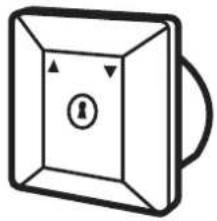
natural_image
Simple line drawing of a rectangular box with an internal circle and directional arrows, no text or symbols present.
natural_image
Simple 3D cube illustration with no text or symbolsArt. No. 25101 / 25103 Art. No. 25102 / 25104 Art. No. 60060 / 60061
natural_image
Five identical 3D geometric shapes arranged horizontally (no text or symbols)Art. No. 60030 / 60031
flowchart
graph TD
    A["+"] --> B["+12V G"]
    B --> C["F01"]
    C --> D["F02"]
    D --> E["F0+"]
    E --> F["G"]
    F --> G["D"]
    G --> H["S"]
    H --> I["G"]
    I --> J["L+"]
    J --> K["L-"]
    K --> L["Lo+"]
    L --> M["Lo-"]
    M --> N["+"]
    O["DC+"] --> P["DC+GND"]
    Q["TX1 RX1"] --> R["F01"]
    S["FO1"] --> T["N.O."]
    U["N.C."] --> V["COM"]
SCHELLENBERG
DE
For warranty claims, spare parts requests or questions regarding the proper installation of your product, please contact our Consumer Service Department. service.int@schellenberg.de