Smart Drive 10 Premium - Automatic gate motor Schellenberg - Free user manual and instructions
Find the device manual for free Smart Drive 10 Premium Schellenberg in PDF.
User questions about Smart Drive 10 Premium Schellenberg
0 question about this device. Answer the ones you know or ask your own.
Ask a new question about this device
Download the instructions for your Automatic gate motor in PDF format for free! Find your manual Smart Drive 10 Premium - Schellenberg and take your electronic device back in hand. On this page are published all the documents necessary for the use of your device. Smart Drive 10 Premium by Schellenberg.
USER MANUAL Smart Drive 10 Premium Schellenberg
natural_image
Line drawing of a mechanical component with a recessed top and side features (no text or symbols)


natural_image
Assorted mechanical components including a Schellenberg device, frame assembly, and railings (no visible text or symbols)Deutsch 4
English 22
Français 39
Polska 56
Italiano 73


INHALTSVERZEICHNIS
natural_image
Cross-sectional diagram of a structural component with diagonal lines indicating construction or reinforcement (no text or symbols)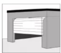
natural_image
Simple line drawing of a building with a diagonal X mark (no text or symbols)
natural_image
Technical line drawing of a mechanical assembly with spring and housing components (no text or symbols)natural_image
Exterior view of a modern white electronic device labeled 'SHELLLENBERG' with a Wi-Fi symbol on the side (no additional text or symbols)
natural_image
Mechanical device with a lever and a rectangular base, no visible text or symbols on the main components
natural_image
Technical line drawing of a mechanical assembly with a suspended cylindrical component (no text or symbols)natural_image
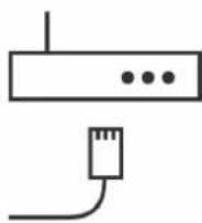
White wireless router with Wi-Fi signal icon and surrounding icons (no text or symbols)Art.Nr. 21000

natural_image
White wireless router with signal icon and Wi-Fi symbol (no text or labels)Art.Nr. 26000
ABUS
Paulmann
Schellenberg
Steinel

www.smart-friends.com
TABLE OF CONTENTS
Safety and notices 23
Basic functions 24
A Installation 25
B Assembly of the 3-piece steel rail 26
C Mounting of the drive 28
D Instructions for the installation 29
E Basic functions, setting and application 30
F Other features and applications 32
Accessories: Smart Friends Box 33
Accessories: Smartphone garage door opener 34
G Manual release 35
H Care and Maintenance 35
I Important explanations for the installer 35
J Important notes for the user 35
K Technical data 36
L Parts list 36
M Warranty 37
N Pairing with the Smart Friends Box 38
natural_image
Pure architectural cross-section diagram without any text, numbers, or symbols

natural_image
Simple line drawing of a building with two crossed X marks (no text or symbols)Copyright protected, 2017 Alfred Schellenberg GmbH. All rights reserved. Any use, in particular reproduction, translation, processing or transmission of content into databases or other electronic media and systems beyond the authorization provided by the copyright legislation is strictly prohibited.
SAFETY AND NOTICES
Dear customers,

read the instructions carefully before installing and operating the product. The installation should be carried out by a qualified specialist. Faulty installation or repairs carried out yourself can lead to injuries, death or damage to property during the operation. Follow all instructions for your own safety, and store this installation manual a safe place.
- The product is designed and manufactured according to local regulations. The installer must be familiar with the local regulations regarding the installation of the drive.
■ Unqualified personnel or persons who are not familiar with the health and safety standards for automatic doors and gates may under no circumstances undertake any installation or intervention work on the product. - Persons who fail to comply with applicable safety standards for installation and maintenance, are responsible for damages, injuries, costs, expenses or claims resulting from non-compliance with the safety standards.
- For an additional safety we recommend the use of a light barrier. Although the product has a pressure-sensitive obstacle detection, an additional light barrier can significantly improve the safety of an automatic garage door.
- Ensure that the garage door is fully open and in the rest position before moving into or out of the garage.
- Ensure that the garage door is fully closed after leaving the garage.
- The safety-obstacle system only works reliably in the case of stationary obstacles. Severe injuries, death and/or material damage may occur when the garage door comes into contact with a moving object (obstacle).
- When using the emergency release, observe that the open garage door can suddenly fall down due to weak or broken springs.
- After installation, check that the product is correctly set and reversed, and that the object is released when the bottom of the gate hits a 50 mm high object that is on the ground. Tip: Use a 50 mm high piece of wood for this.
- Every month, perform a check if the product reverses when the gate hits a 50mm high obstacle on the ground. If necessary, perform an adjustment and check, since an incorrect setting poses a danger.
- The garage door should be balanced. Immovable or difficult to reach gates must be repaired. In an unbalanced condition, garage doors, door springs, cables, windows, brackets and rails are under extreme tension, which can lead to serious injuries. Do not attempt to detach, move, or straighten the gate. Seek the assistance of a garage door specialist.
- Check the system regularly, in particular, cables, springs and brackets for signs of wear, damage or imbalance. Do not use the product if a repair or modification of the setting is required.
- Children may not carry out any cleaning or repairs on the product without supervision.
- If the power cord is damaged, it must be replaced by the manufacturer, its customer service or a similarly qualified person.

During the cleaning, maintenance and replacement of parts, the garage door drive must be disconnected from the mains.
- Do not allow children to play with the unit, including the remote controls. Remote controls must be kept away from children.
- Observe the moving door. Persons are not allowed to be in the danger area of the garage door until the door is fully opened or closed.
- An incorrect setting can pose a danger. If the readjustment does not restore the fault-free function, call the authorized service.
■ Before installing the product, remove all unnecessary ropes or chains and deactivate all hardware such as locks that are not required when using a garage door drive. - Install all switches at a height of at least 1.5 m and within sight of the garage door, but away from moving parts and out of the reach of children.
- Fasten the warning notices against pinching in a clearly visible place or near the switch.
- Attach the label for the manual release near the product.
- The product may not be used with a garage door which has a hatch door.
■ After the installation, check that parts of the gate do not protrude onto public footpaths or roads during the operation.
BASIC FUNCTIONS
Congratulations on purchasing this product. The garage door drive has been developed with state-of-the-art technical knowledge, and manufactured using the most reliable and modern electrical / electronic components.
The garage door drive is programmed directly on the device. The control is performed via the supplied hand-held transmitter, or with a smartphone or tablet via the App. For the control with the App, you will need the Smart Friends Box (not included in the scope of delivery).
■ Softstart, Softstopp - The door operator starts and stops gently, almost silently.
■ Self-learning force adjustment
- Overload protection - when closing, the gate moves back approx. 15 cm, or stops when opening.
■ Adjustable force setting for the safety return.
- Low voltage protection - The drive does not operate at a too low voltage, to prevent the drive from being damaged.
- Hopping code technology of the hand-held transmitter - Prevents the intrusion of unauthorized persons reliably.
- Option for the connection of a wall switch.
- Option to connect a light barrier - The gate is reversed when an obstacle is detected.
Do not dispose of together with household waste. The product is recyclable and can be deposited at a recycling centre or a collection station for electrical household waste.
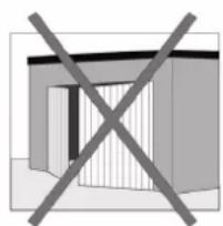
A INSTALLATION
- Read the instructions carefully.
- The garage door must be suitable for the use with the door drive.
- The door must be able to move lightly and freely.
- The door must be balanced and easy to move with the hand.
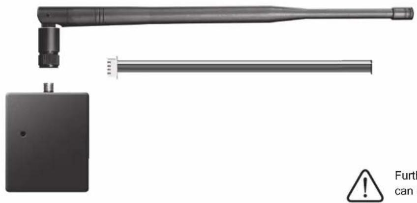
Fig. 1
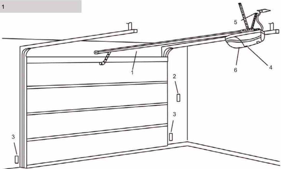
1 Rail
2 Wall button (optional)
3 Light barrier (optional)
4 Settings screen
5 Power connection
6 Door drive
Fig. 2 Fig. 3
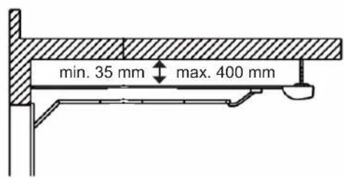
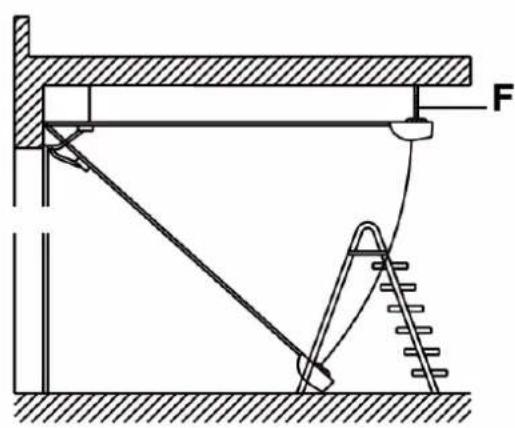

A minimum space requirement of 35 mm is required (Fig. 2). The rail must be mounted horizontally to the drive shaft. Ensure that the mounting rail (F) is securely installed (Fig.3). Faulty attachment of the garage door drive can lead to personal injury and property damage.
B ASSEMBLY OF THE 3-PIECE STEEL RAIL
Fig. 4
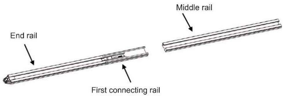
Fig. 5
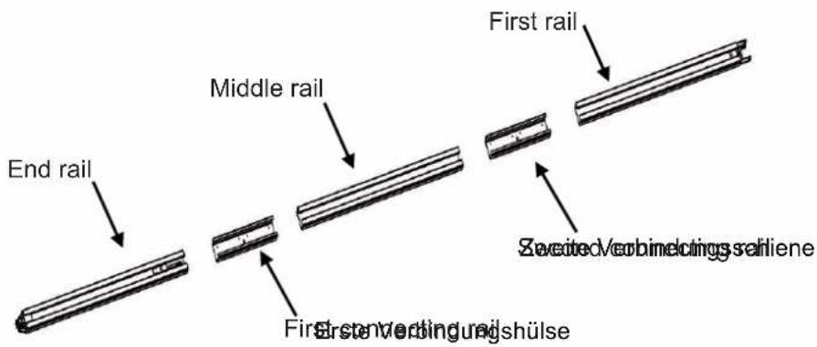
Fig. 6
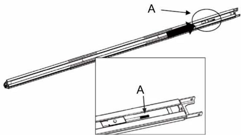
Fig. 7

natural_image
Technical line drawing of a mechanical assembly with springs and housing (no text or symbols)- Slide the rail together (Fig. 4).
- Slide the second connecting rail over the end of the middle rail (Fig. 5).
- Remove the cable tie.
- Pull the screw rod A with the chain to the end of the top rail (Fig. 6).
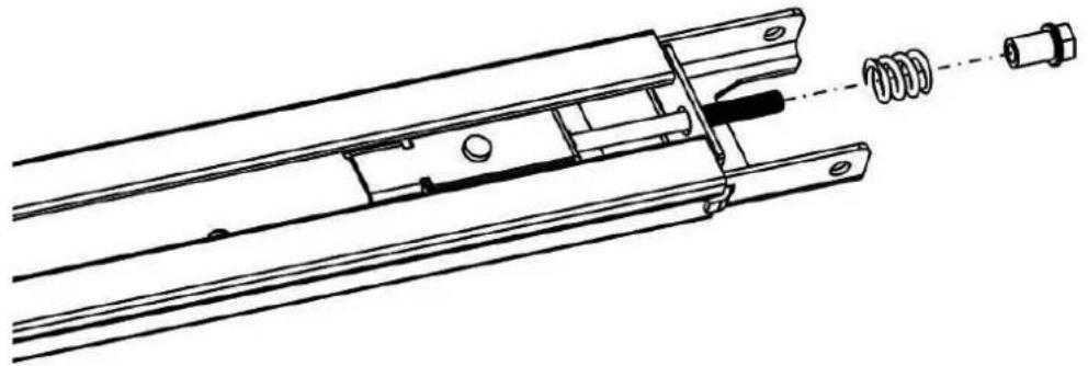
- Connect the bolt and the spring, and terminate it with the nut (Fig. 7).
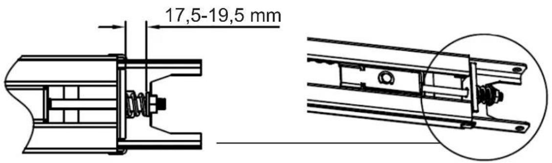
- Tighten the bolt in the correct position (Fig. 8) and cut the cable ties close to the gear wheel. The rail is now mounted.
- Tension the chain by turning the bolt. The optimum chain tension is set when the spring is tensioned to a length of 17.5 - 19.5 mm (Fig. 8).
Fig. 8
C MOUNTING OF THE DRIVE
Fig. 9
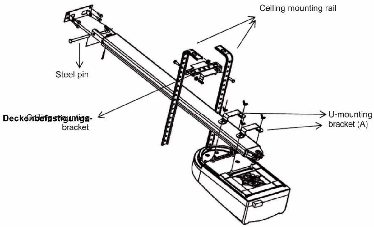
Fig. 10
D INSTRUCTIONS FOR THE INSTALLATION
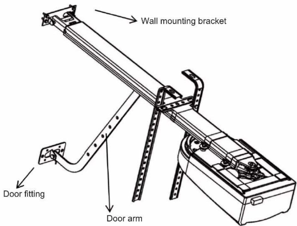
- Fasten the wall mounting fitting approx. 2 - 15 cm (depending on the space) above the upper door middle part (Fig. 9).
- Fasten the rail with the steel pin (Fig. 9).
- Use the U-mounting brackets (A) to fasten the door drive to the rail (Fig. 9).
- Fasten the door drive with the ceiling mounting rails on the garage ceiling (Fig. 9).
Important: The door drive must be fastened so that the rail is aligned horizontally. The ceiling mounting rail must be attached securely.
- Fasten the door hinge to the garage door (Fig. 10).
- Attach the straight and curved door arm (Fig. 10).
- Attach the unlocking cable to the carriage (Fig. 13).
- Pull the release part and disconnect the carriage from the door drive. Perform a manual test by manually opening and closing the door. The door must be able to move without resistance.
- Plug the mains plug of the door drive into a suitable socket (230V / 50Hz).
Important: Ensure that your garage door drive is connected to the power supply (230V / 50Hz).
INSTRUCTIONS FOR THE INSTALLATION
- Follow the regulations and safety standards for electrical installations of automatic gates.
- Be sure to observe the following points to ensure the maximum degree of safety and reliability of your door drive.
- Before commissioning your door drive, ensure that there are no obstacles in the area of the door drive.
- Check your power supply. The values must match with the values in these operating instructions. This information can also be found on the rating plate of the drive.
- The electricity connection in the garage must comply with local regulations.
- The controller of the device can be damaged if the door drive has been installed incorrectly.
- Check the completeness of all parts and accessories before the installation.
- Read the instructions carefully.
- Ensure that your garage door is in good condition before starting the installation. It should move lightly and without resistance.
- Observe the minimum distances during assembly as described in the drawings.
- Use an optional light barrier for your additional safety, and check the automatic safety return regularly.
- Follow the instructions and notes in this manual. If you are unsure about the installation, please contact our customer service (see back cover).
E BASIC FUNCTIONS, SETTING AND APPLICATION
SETTING OF THE END POSITION
Automatic force setting
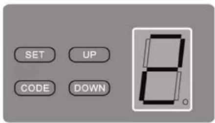
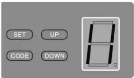
Press the SET button until the display shows „1“. Set the upper end position of the door by pressing the UP button. Wait approx. 10cm before the upper door position is reached, release the UP button. Now, press the UP button several times to move the door to the desired upper door position and complete the process by pressing the SET button.
The display will now show „2“. Now, set the lower end position of the door by pressing the DOWN button. Wait approx. 10cm before reaching the lower door position, release the DOWN button. Now, press the DOWN button briefly to bring the door to the desired lower door position, and then press the SET button to complete the operation.
Your door drive will now perform a complete movement cycle independently, learn the positions and set the automatic force setting.
Please open and close the door another 5 times.
INCORRECT SETTING OF THE END POSITION
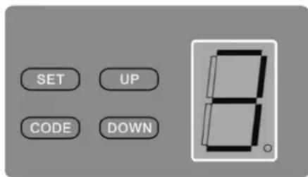
If the door drive does not perform an independent learning movement, an „E“ will be shown in the display. The lower door position is set incorrectly. The door presses too strong onto the floor, the closing force of the door is too high.
Please disconnect the garage door drive for 10 seconds from the power supply, and repeat the settings for the automatic force setting, and slightly lower the door less when setting the lower door position.
SETTING THE RECEIVER AND HAND-HELD TRANSMITTER
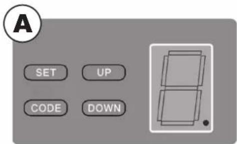
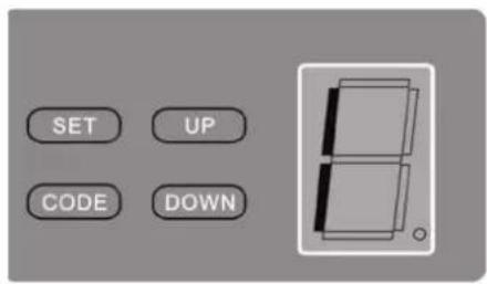
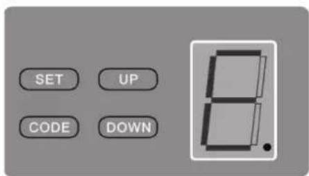
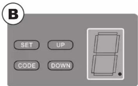
Press the CODE button until the LED dot is illuminated (Fig. A). Now press any button on your hand-held transmitter. The LED dot will switch off. Press the menu button on the hand-held transmitter again. The LED will now flash quickly and the LED display will show „ii“ (fig. B).
If you have several hand-held transmitters, repeat the procedure accordingly.
To clear all codes, press the CODE button on the unit for approx. 8 seconds until the LED display shows „C“.
OPTIONAL FORCE SETTING
The factory-set forces (value 3) are designed to enable a smooth operation of standard doors (which are intended for use with this drive). The forces exerted in the factory setting should fundamentally be sufficient to completely open and close the door to be operated. In the factory default setting, the drive complies with the legal or relevant standards (for example, EN 13241-1, EN 12453, EN 60335-2-95) pertaining to the requirements for the operating forces and therefore the maximum permissible force limits.
However, the forces to be exerted by the drive can also be reduced (values 1-2) or increased (values 4-9) by the procedure described below.
Note:
This could be required, for example, if the "Door open" or "Door closed" end stops are not reached with the factory default setting (value 3). Then the setting for the maximum force - as described below - must be incrementally increased until the respective end stop is reached.
In addition, the running behaviour of the door may deteriorate (for example, through a depletion of the spring tension) throughout the course of the operating time. For safety reasons, it could then be necessary to adjust the forces, because a manual actuation which could then be necessary to open or close the door might entail a safety hazard (for example, an uncontrolled closing of the door) for persons and property.
But

CAUTION:
An increased setting which deviates the factory default setting (value 3) can lead to serious personal injury and even a mortal danger, as well as severe property damage.
An increased force value which deviates from the factory default setting increases the forces exerted onto the door during the opening and closing motion. When the factory default setting is changed there is a danger of serious personal injury up to mortal danger through a possible jamming or crushing of persons or items within in the gate area, as well as the risk of damage to property, since a force setting which deviates from the factory default setting can possibly lead to an exceeding of the specified maximum permissible force limits. Therefore, the following shall apply:
Note:
After each force setting change (values 4–9) which deviates from the factory default setting (value 3), the full compliance with the statutory or relevant standards regarding the force limit values must be checked, approved and documented by a competent person, in order to exclude the indicated dangers for life and limb.
Procedure for changing the factory default setting:
Please note again that the limits of the forces defined by the law may not be exceeded! Therefore, you should check the compliance with these limit values for each deviation from the factory default setting for the force setting (values 4-9) as described in the bold printed note above.
Press the SET button until the LED display shows „3“. For a higher force setting, press the UP button, and the DOWN button for a lower force setting. Values from 1 to 9 can be set.
SETTING THE LIGHT BARRIER
Press the DOWN button until the LED shows "II". Press the UP button to activate the light barrier function. The LED shows "H". To deactivate, press the DOWN button. The LED shows „II“. To confirm, press the SET button. Connect the light barrier as described in Figure 12.
Important: If you are not using a light barrier, the light barrier function absolutely must be switched off. Otherwise, the door drive will not function.
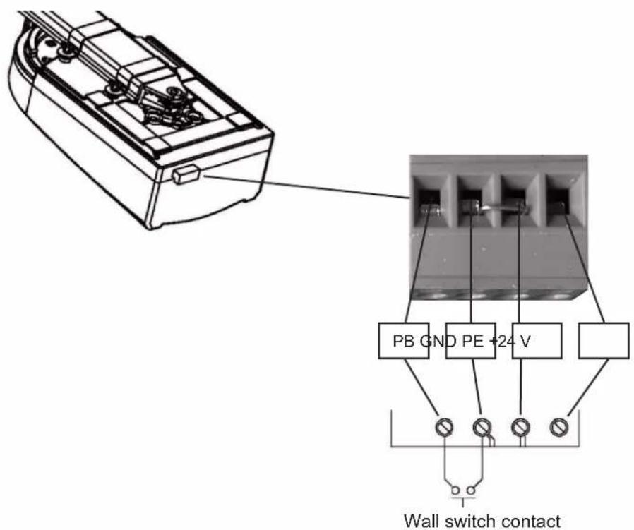
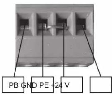
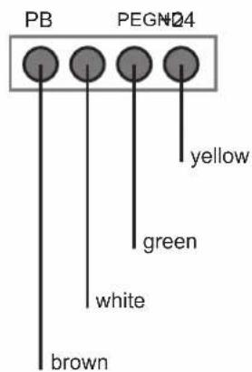
CONNECTION OF A WALL SWITCH
Connect the optional wall switch to the door drive (Fig. 11).
F OTHER FEATURES AND APPLICATIONS
- In order to connect a further wall switch, please refer to the connection diagram (Fig. 11).
- In order to connect a light barrier, please refer to the connection diagram (Fig. 12).
Fig. 11
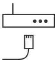
ACCESSORIES: SMART FRIENDS BOX
For smartphone control via the App, we recommend the Smart Friends Box. This used to control all Schellenberg wireless products via App. You can then use this product as a smart standalone solution, or integrate it into automated actions.

Item No.: 26000

natural_image
White smart device labeled 'Smart Friends' on a square base (no additional text or symbols visible)
Further information on the product and the App can be found at www.smart-friends.com
For smartphone control via the App, we recommend the Schellenberg Smart Home garage door opener. With this, the garage door can be easily operated with a smartphone.
Item No.: 60999
natural_image
Mechanical device with a lever and connector, no visible text or symbols
Further information on the product and the App can be found at www.schellenberg.de.
CONNECTING THE SMARTPHONE GARAGE DOOR OPENER
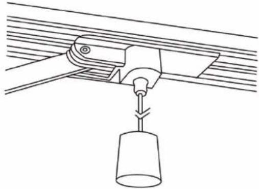
G MANUAL RELEASE
As described in Fig. 13, you can separate the carriage from the door drive. Pull on the handle and move the door manually. The door drive automatically reconnects with the door when you start it. If you do not have an internal access door to the garage, we recommend the use of an emergency unlocking lock (item no. 60511).

Fig. 13
natural_image
Technical line drawing of a mechanical lifting device with a conical cup, no text or symbols presentH CARE AND MAINTENANCE
The electronic controller does not require any special care or maintenance. Check your garage door monthly for ease of movement.
In the monthly cycle, also check the force setting for the automatic return and, if activated, check the function of the light barrier.

A sluggishly moving and poorly installed garage door will have a direct impact on the service life of your door drive.
I IMPORTANT EXPLANATIONS FOR THE INSTALLER
It is important that the user is familiar with the functions of the door drive. When the force setting is changed, the safety device must absolutely be checked by a competent person. We recommend an annual inspection of the safety equipment by a competent person.
J IMPORTANT NOTES FOR THE USER
Do not operate the door drive when people are in the vicinity. The hand-held transmitters are not suitable for children and should be stored accordingly. Repairs and other services must be carried out by appropriately trained and qualified personnel.
Important: In the event of a malfunction, please contact our customer service (see back cover). Never attempt to repair the drive yourself.
K TECHNICAL DATA
| Model / type | Smart DRIVE 10 PREMIUM / 60912 (DE), 60916 (INT) | Smart DRIVE 14 PREMIUM / 60915 (DE), 60914 (INT) |
| Power Input | 220 – 240 V AC 50/60 Hz | 220 – 240 V AC 50/60 Hz |
| Power output | 200 W | 245 W |
| Maximum force | 600 N | 1.000 N |
| Speed | 0.15 m/sec. | 0.15 m/sec. |
| Lighting | LED, 24 V DC | LED, 24 V DC |
| Lighting time | 3 min. | 3 min. |
| Coding | Hopping code | Hopping code |
| Storm supply transmitter | 23 A 12 V battery | 23 A 12 V battery |
| Frequency | 433,92 MHz | 433,92 MHz |
| Operating temperature | -20° to +40°C | -20° to +40°C |
| Max. Door size | 10 m^2 | 14 m^2 |
| Protection class | only for dry rooms | only for dry rooms |
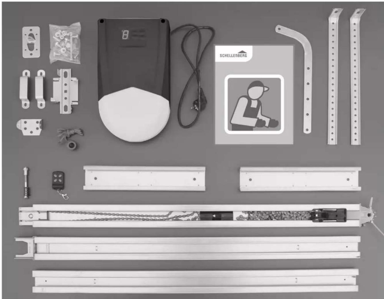
L PARTS LIST
| Part Amount | |
| Garage door drive 1 | |
| Rail 1 | |
| Hand-held transmitter 1 | |
| Door bracket 1 | |
| Wall bracket 1 | |
| Ceiling mount 2 | |
| Release with handle 1 | |
| Door arm 1 | |
| Mounting material 1 | |
| M6 nut 2 | |
| M8 nut 4 | |
| M6 x 14 Hex screw 2 | |
| M8 x 14 Hex screw 4 | |
| M8 x 25 axle pin 1 | |
| M8 x 90 axle pin 1 | |
| M1.8 x 38 split pin | 2 |
| U-mounting bracket | 2 |
M WARRANTY
Dear customer,
dear customer, thank you very much that you have decided to purchase a SCHELLENBERG product. all of our products are tested and subjected to the scrutiny of the Schellenberg quality assurance. The statutory warranty period is 24 months from the date of purchase in all EU countries. The statutory warranty / guarantee conditions of the respective country apply outside the EU.
In case of a warranty case at our discretion we will repair the product, or exchange it for an equivalent SCHELLEN-BERG product. The warranty period is not extended by the replacement or repair of the product! A condition for a warranty claim processing is the presentation of the original sales receipt. When shipping the product please include a copy of the original sales receipt and a description of the occurred defect.
The following are excepted from the warranty:
■ use-related, normal wear and tear
- improper installation, connection, operation or treatment
■ acts of God or other external influences
- improper maintenance or repairs by third parties
■ technical modifications by third parties
We wish to point out explicitly that electrical work may only be carried out by qualified and authorised electricians! Replaced units shall become our property. Any claims to compensatory damages are hereby excluded unless they are due to malice aforethought or gross negligence on the part of the manufacturer. No claims going beyond this on the basis of warranty obligations will be entertained.
Replacement or repair of the device will not extend the warranty period! The period of warranty is not extended as a result of replacement or repair of the device! If you need to make a claim under warranty or need spare parts then please contact the dealer who sold you the product.
Terms and conditions of the additional motor warranty for the garage door drives:
This manufacturer warranty is valid for the end purchaser of the device (customer). Legal claims of the customer or claims of the customer against the seller / dealer of the device are consequently neither excluded nor restricted.
The warranty period for the drive motor is
- Smart DRIVE 10 PREMIUM, 4 years = 48 months
- Smart DRIVE 14, PREMIUM 6 years = 72 months
from the date of purchase of the device by the original customer.
The warranty relates solely to the electric motor as an individual component of the garage door drive not exhibiting any defects in material or workmanship. It does not relate to any other mechanical or electrical components that are also connected to the electric motor within the product.
During the period of warranty devices that show a defect of the type described above will at the sole choice of Schellenberg either be repaired or else the entire garage door drive or parts of it will be replaced. Any replaced parts or equipment will become the property of Schellenberg.
The warranty will neither be extended nor renewed for repaired or replaced devices.
This warranty does not apply if the defect is caused by one of the following causes.
a) The garage door drive is not suitable for the garage door to be operated. Taking into account the operating instructions of the door manufacturer.
b) The maintenance and operating instructions of the door manufacturer were not followed.
c) The maintenance and service instructions of the drive manufacturer (e.g. safety switch-off test etc.) have not been followed.
In order for claims made under warranty to be valid the customer report the defect or fault to Schellenberg within a period of 10 days of becoming aware of the defect. To do this, a legible and unmodified receipt from the seller/dealer or from Schellenberg must be sent in as proof of purchase. Schellenberg is not liable under this warranty for collateral damage, consequential damage or direct damage, costs or expenses. Statements going beyond this warranty declaration and made in oral form or in writing without the approval of Schellenberg shall be invalid. Any changes made to this warranty shall likewise require the prior written approval of Schellenberg.
We hope that you will enjoy using the product that you have bought.
The team from Schellenberg
N PAIRING WITH THE SMART FRIENDS BOX
Pair the product with the Smart Friends System, and control all „Ready for Smart Friends“ products through the Friends app.

Security Tech Germany

Paulmann

SCHELLENBERG

Intelligent technology


[Non-Text]


www.smart-friends.com
TABLE DES MATIÈRES
natural_image
Pure architectural cross-section diagram without any text, numbers, or symbols
natural_image
Simple line drawing of a building with a diagonal X mark (no text or symbols)Chères clientes, chers clients,

natural_image
Technical line drawing of a mechanical assembly with spring and housing components (no text or symbols)natural_image
White smart device labeled 'Smart Friends' on a plain background (no additional text or symbols visible)
natural_image
Diagram showing a mechanical device with a shaft and connector, plus a warning symbol (no readable text or labels)
natural_image
Technical line drawing of a mechanical lifting device with a conical weight (no text or symbols)H ENTRETIEN ET MAINTENANCE

Security Tech Germany

Paulmann

SCHELLENBERG

Intelligent technology


[Non-Text]


www.smart-friends.com
SPIS TREŚCI
natural_image
Pure architectural cross-section diagram without any text, numbers, or symbols
natural_image
Simple line drawing of a building with two crossed X marks (no text or symbols)
natural_image
Technical line drawing of a mechanical assembly with spring and housing components (no text or symbols)
natural_image
White rectangular electronic device labeled 'Smart Friends' with a smiley face logo on the front panel (no additional text or symbols visible)
natural_image
Mechanical device with a black rectangular base and a long rod, accompanied by a warning symbol (no text or labels on the main components)
natural_image
Technical line drawing of a mechanical assembly with a suspended cylindrical component (no text or symbols)
H PIELEGNACJA I KONSERWACJA
I WAŻNE OBJAŚNIENIA DLA INSTALATORA
J WAŻNE INFORMACJE DLA UŻYTKOWNIKA

Security Tech Germany

Paulmann

SCHELLENBERG

Intelligent technology


[Non-Text]


www.smart-friends.com
INDICE
natural_image
Pure architectural cross-section diagram without any text, numbers, or symbols
natural_image
Simple line drawing of a building with a diagonal X mark (no text or symbols)natural_image
Technical line drawing of a mechanical assembly with springs and housing (no text or symbols)natural_image
White smart device labeled 'Smart Friends' on a square base (no additional text or symbols visible)
natural_image
Diagram showing a mechanical device with a shaft and connector, alongside a black rectangular component and warning symbol (no readable text or labels)
natural_image
Technical line drawing of a mechanical device with a suspended weight (no text or symbols)N ACCOPPIAMENTO CON SMART FRIENDS BOX

Security Tech Germany

Paulmann

SCHELLENBERG

Intelligent technology


[Non-Text]


www.smart-friends.com

| _1^2 | _2^2 | _3^2 | _4^2 | |
| _5^2 | _6^2 | _7^2 | _8^2 | _9^2 |
| _10^2 | _11^2 | _12^2 | _13^2 | _14^2 |
| _11^2 | _12^2 | _13^2 | _14^2 | _15^2 |
| _12^2 | _13^2 | _14^2 | _15^2 | _16^2 |
| _13^2 | _14^2 | _15^2 | _16^2 | _17^2 |

For warranty claims, spare parts requests or questions regarding the proper installation of your product, please contact our Consumer Service Department. service.int@schellenberg.de