
EN424MP - Multifunction tool MAKITA - Free user manual and instructions
Find the device manual for free EN424MP MAKITA in PDF.
| Brand | Makita |
| Model | EN424MP |
| Product type | Mower head (accessory for multi-tool) |
| Cutting width | 330 mm |
| Dimensions (L x W x H) | 820 mm x 350 mm x 191 mm |
| Net weight | 2,3 kg |
| Power source | Battery (via compatible power head) |
| Compatible power heads | DUX60, DUX18, UX01G |
| Intended use | Cutting grass and weeds on the ground |
| Blade type | Shear blades (upper and lower) |
| Cutting angle adjustment | Yes, by wheel position |
| Guaranteed sound power level | Compliant with directive 2000/14/EC |
| Required protective equipment | Helmet, glasses, ear defenders, gloves, sturdy boots |
| Safety distance | 15 m from bystanders and animals |
| Blade maintenance | Low viscosity oil before use and after cleaning |
| Motor axle lubrication | Makita grease No. 2 or equivalent every 30 h |
| Grease lubrication (blades) | Every 50 h, approx 1.5 g per hole |
| Storage | Blade cover in place, dry place, out of reach of children |
| Spare parts available | Shear blade set, Makita battery and charger |
| Repairability | Authorized Makita service center |
Frequently Asked Questions - EN424MP MAKITA
User questions about EN424MP MAKITA
0 question about this device. Answer the ones you know or ask your own.
Ask a new question about this device
Download the instructions for your Multifunction tool in PDF format for free! Find your manual EN424MP - MAKITA and take your electronic device back in hand. On this page are published all the documents necessary for the use of your device. EN424MP by MAKITA.
USER MANUAL EN424MP MAKITA

natural_image
Diagram of a mechanical device with two wheels and a labeled component (no text or symbols)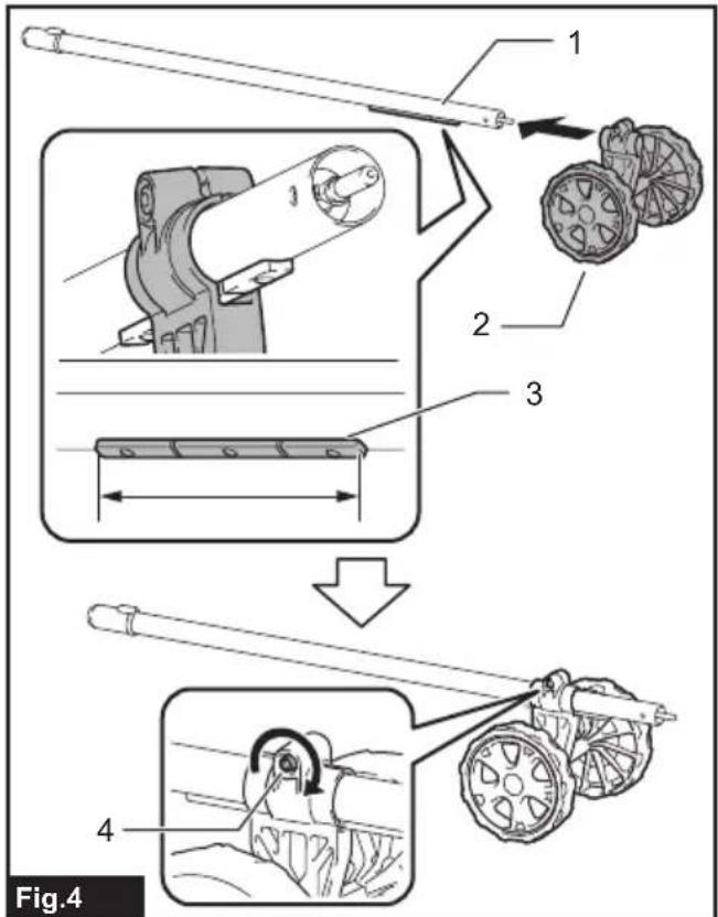
natural_image
Technical illustration of a mechanical assembly with a battery and component labeled '1', no text or symbols present.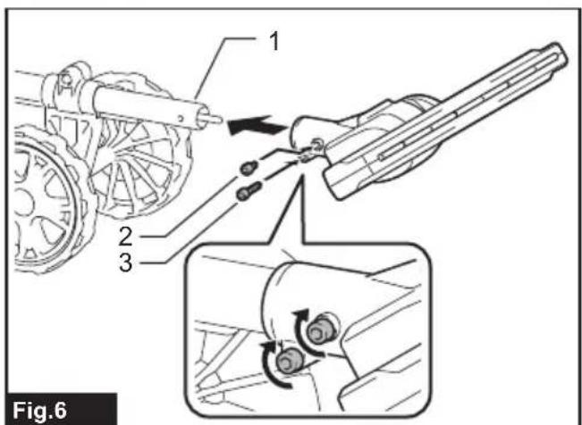
natural_image
Technical diagram of a mechanical device with labeled component '1' and directional arrow (no text or symbols beyond label)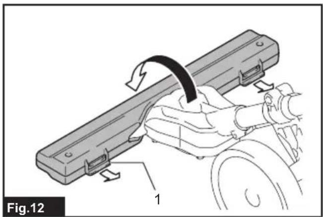
natural_image
Mechanical assembly diagram showing a lever mechanism with a curved arrow and labeled component (no text or symbols beyond label)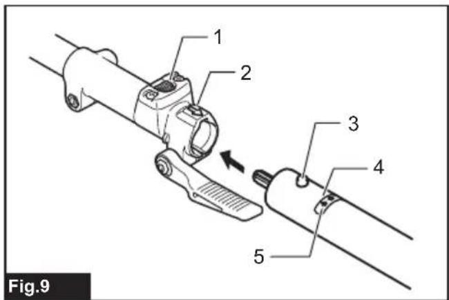
natural_image
Technical illustration of a mechanical component with a hand adjusting a slot (no text or symbols present)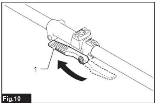
natural_image
Mechanical device diagram showing a lever mechanism with a curved arrow indicating motion (no text or symbols present)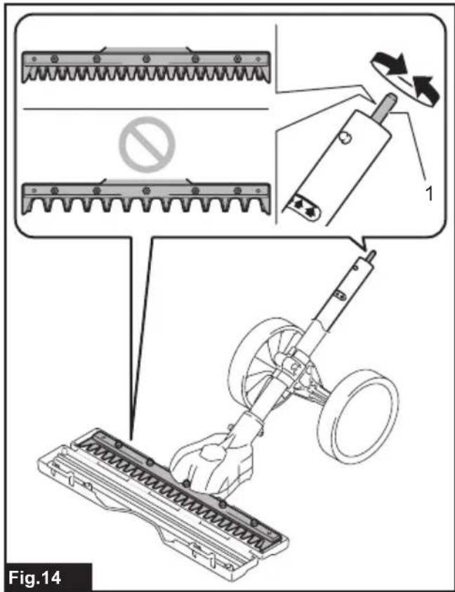

natural_image
Technical illustration of a mechanical assembly with a bracket and wheels, showing an upward force arrow (no text or symbols)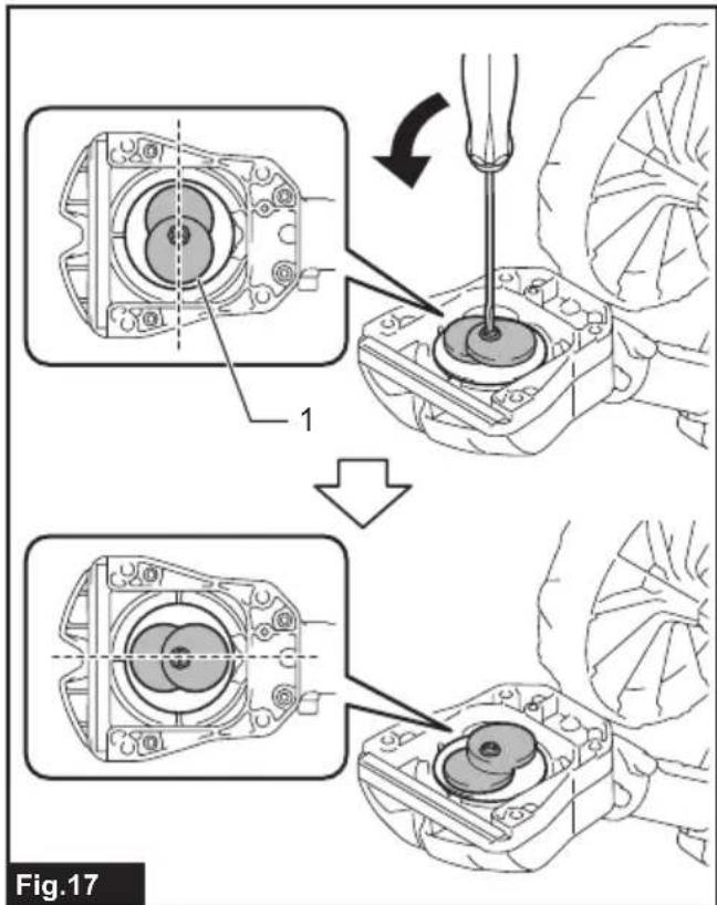

natural_image
Mechanical assembly diagram showing a bracket being lifted by a pulley system (no text or symbols)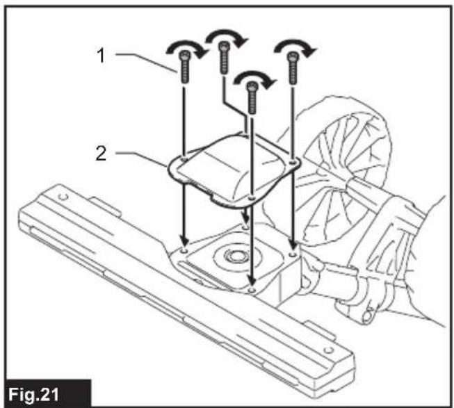
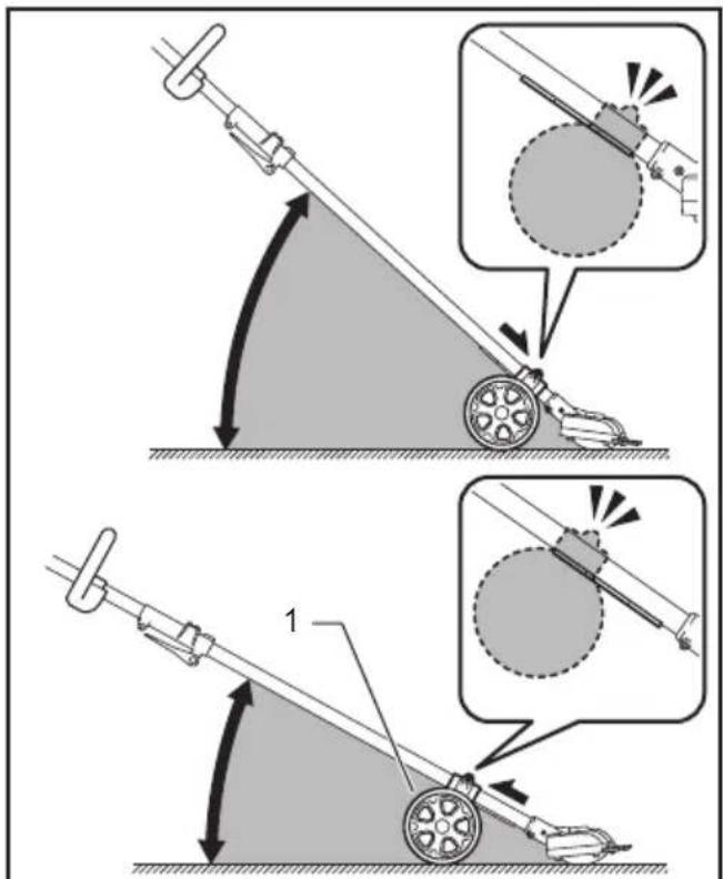
Fig.22
natural_image
Diagram showing a crossed-out circle enclosing a field with plants and fruit, labeled Fig.23 (no text or symbols on the diagram itself)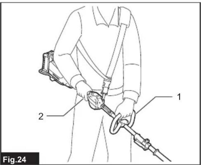
natural_image
Person in protective gear using a manual leach tool to clean grass or gravel (no text or symbols visible)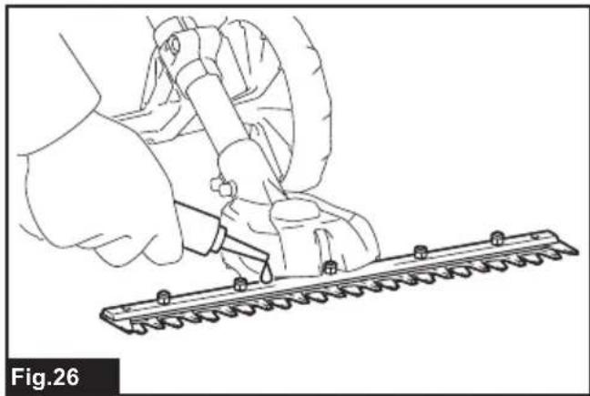
natural_image
Line drawing of a hand using a tool to cut a saw blade, no text or symbols present
natural_image
Line drawing of a hand using a tool to cut a mechanical part, labeled Fig.27 (no text or symbols on the diagram itself)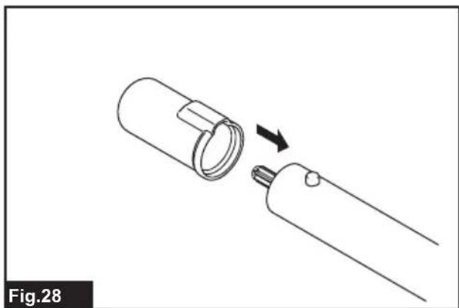
natural_image
Diagram of a mechanical device with a cylindrical component and a separate cylindrical component, showing an arrow indicating assembly or transformation (no text or symbols present)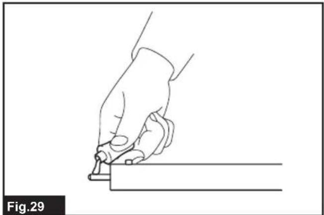
natural_image
Line drawing of a hand holding a tool, poised to write on a rectangular object (no text or symbols)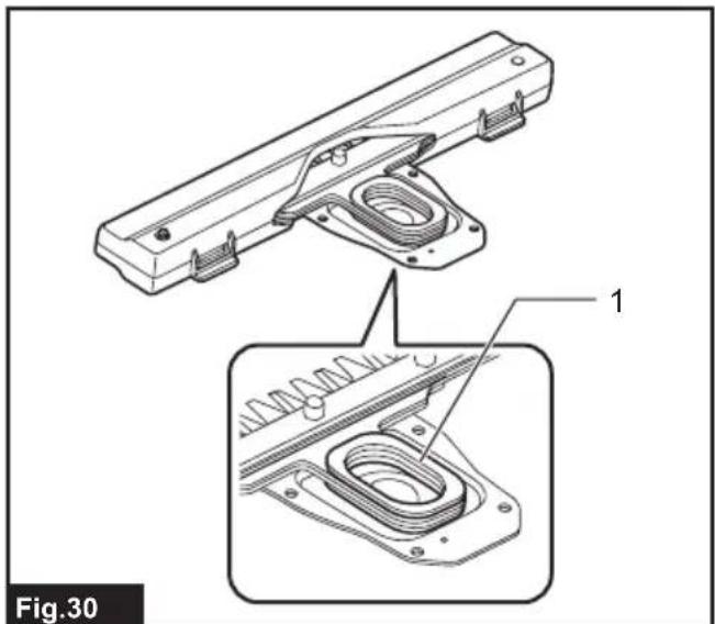
natural_image
Technical line drawing of a mechanical assembly with labeled parts, showing exploded and assembled views (no text or symbols present)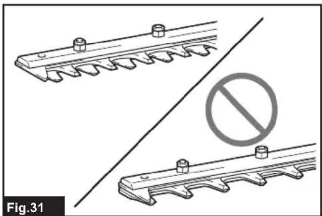
natural_image
Technical illustration of two mechanical components with a prohibition symbol (no text or labels)
natural_image
Technical diagram showing mechanical assembly with a highlighted section and numbered marker (no readable text or symbols)SPECIFICATIONS
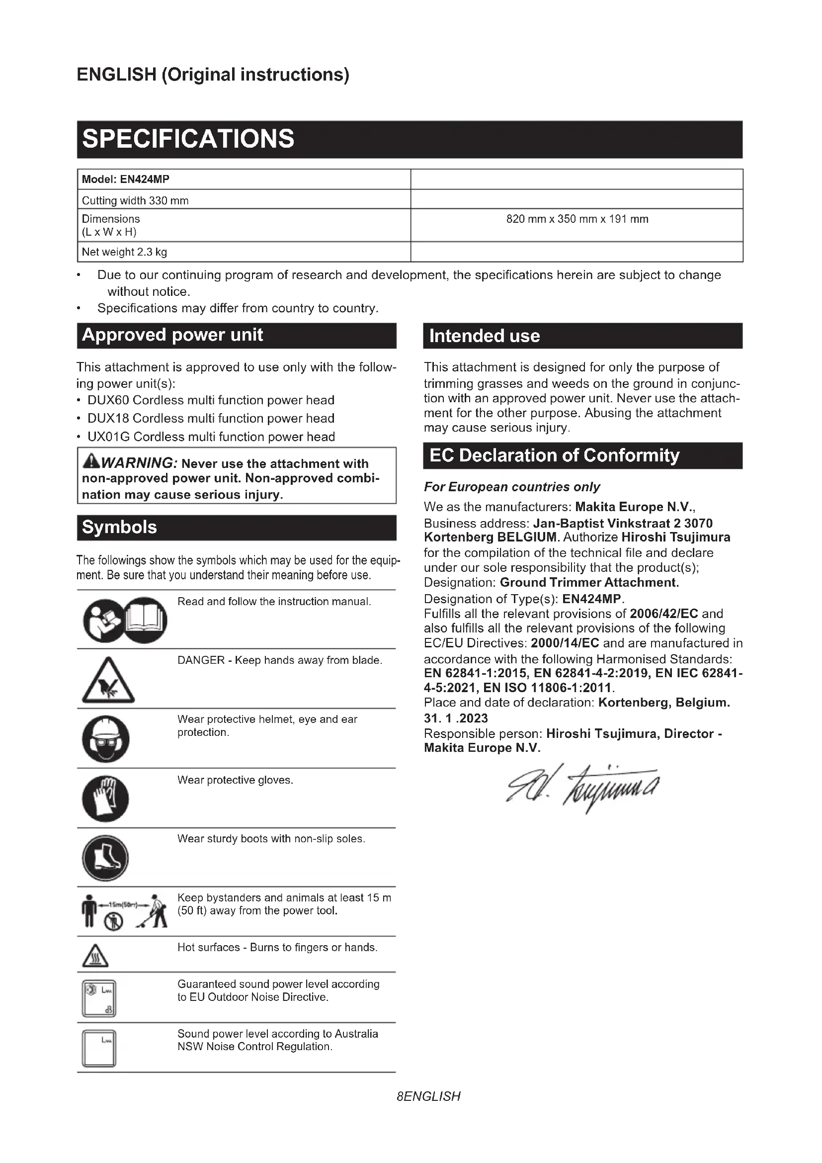
| Model: EN424MP | |
| Cutting width 330 mm | |
| Dimensions(L x W x H) | 820 mm x 350 mm x 191 mm |
| Net weight 2.3 kg |
- Due to our continuing program of research and development, the specifications herein are subject to change without notice.
• Specifications may differ from country to country.
Approved power unit
This attachment is approved to use only with the following power unit(s):
- DUX60 Cordless multi function power head
• DUX18 Cordless multi function power head - UX01G Cordless multi function power head
WARNING: Never use the attachment with non-approved power unit. Non-approved combination may cause serious injury.
Symbols
The followings show the symbols which may be used for the equipment. Be sure that you understand their meaning before use.

Read and follow the instruction manual.

DANGER - Keep hands away from blade.

Wear protective helmet, eye and ear protection.

Wear protective gloves.

Wear sturdy boots with non-slip soles.

Keep bystanders and animals at least 15 m (50 ft) away from the power tool.

Hot surfaces - Burns to fingers or hands.

Guaranteed sound power level according to EU Outdoor Noise Directive.

Sound power level according to Australia NSW Noise Control Regulation.
Intended use
This attachment is designed for only the purpose of trimming grasses and weeds on the ground in conjunction with an approved power unit. Never use the attachment for the other purpose. Abusing the attachment may cause serious injury.
EC Declaration of Conformity
For European countries only
We as the manufacturers: Makita Europe N.V.,
Business address: Jan-Baptist Vinkstraat 2 3070
Kortenberg BELGIUM. Authorize Hiroshi Tsujimura
for the compilation of the technical file and declare under our sole responsibility that the product(s);
Designation: Ground Trimmer Attachment.
Designation of Type(s): EN424MP.
Fulfills all the relevant provisions of 2006/42/EC and also fulfills all the relevant provisions of the following EC/EU Directives: 2000/14/EC and are manufactured in accordance with the following Harmonised Standards: EN 62841-1:2015, EN 62841-4-2:2019, EN IEC 62841-4-5:2021, EN ISO 11806-1:2011.
Place and date of declaration: Kortenberg, Belgium. 31. 1. 2023
Responsible person: Hiroshi Tsujimura, Director - Makita Europe N.V.
- hyuunna
Declaration of Conformity (For UK)
For UK only
We as the manufacturers: Makita Europe N.V., Business address: Jan-Baptist Vinkstraat 2 3070 Kortenberg BELGIUM. Authorize Hiroshi Tsujimura for the compilation of the technical file and declare under our sole responsibility that the product(s); Designation: Ground Trimmer Attachment.
Designation of Type(s): EN424MP. Fulfills all the relevant provisions of S.I. 2008/1597 (as amended) and also fulfills all the relevant provisions of the following UK Regulations: S.I. 2001/1701 (as amended) and are manufactured in accordance with the following Designated Standards: EN 62841-1:2015, EN 62841-4-2:2019, EN IEC 62841-4-5:2021, EN ISO 11806-1:2011.
Place and date of declaration: Kortenberg, Belgium. 31. 1. 2023
Responsible person: Hiroshi Tsujimura, Director - Makita Europe N.V.
Importer: Makita (UK) Limited, Michigan Drive, Tongwell, Milton Keynes, Buckinghamshire, MK15 8JD, UK

SAFETY WARNINGS
Cordless Grass Shear Safety Warnings
- Do not use the grass shear in bad weather conditions, especially when there is a risk of lightning. This decreases the risk of being struck by lightning.
- Keep all power cords and cables away from cutting area. Power cords or cables may be hidden and can be accidentally cut by the blade.
- Wear ear protection. Adequate protective equipment will reduce the risk of hearing loss.
- Hold the grass shear by insulated gripping surfaces only, because the blade may contact hidden wiring. Blades contacting a "live" wire may make exposed metal parts of the grass shear "live" and could give the operator an electric shock.
- Keep all parts of the body away from the blade. Do not remove cut material or hold material to be cut when blades are moving. Blades continue to move after the switch is turned off. A moment of inattention while operating the grass shear may result in serious personal injury.
-
When clearing jammed material or servicing the grass shear, make sure the power switch is off and the battery pack is removed or disconnected. Unexpected actuation of the grass shear while clearing jammed material or servicing may result in serious personal injury.
-
Carry the grass shear by the handle with the blade stopped and taking care not to operate the power switch. Proper carrying of the grass shear will decrease the risk of inadvertent starting and resultant personal injury from the blades.
- When transporting or storing the grass shear, always use the blade cover. Proper handling of the grass shear will decrease the risk of personal injury from the blades.
Additional Safety Instructions
General instructions
- To ensure correct operation, user has to read this instruction manual to make himself familiar with the handling of the equipment. Users insufficiently informed will risk danger to themselves as well as others due to improper handling.
-
Never allow children, persons with reduced physical, sensory or mental capabilities or lack of experience and knowledge or people unfamiliar with these instructions to use the machine, local regulations may restrict the age of the operator.
-
Use the equipment with the utmost care and attention.
-
Operate the equipment only if you are in good physical condition. Perform all work calmly and carefully. Use common sense and keep in mind that the operator or user is responsible for accidents or hazards occurring to other people or their property.
-
Never operate the machine while people, especially children, or pets are nearby.
-
The motor is to be switched off immediately in case that the equipment shows any problem or abnormal sign.
-
Switch off and remove the battery cartridge when resting and when leaving the equipment unattended, and place it in a safe location to prevent danger to others or damage to the equipment.
-
Avoid using the machine in bad weather conditions especially when there is a risk of lightning.
Personal protective equipment
-
Wear eye protection and stout shoes at all times while operating the machine.
-
Always wear substantial footwear and long trousers while operating the machine.
Starting up the equipment
-
Make sure that there are no children or other people nearby, also pay attention to any animals in the working vicinity. Otherwise stop using the equipment.
-
During operation, keep bystanders or animals at least 15 m away from the tool. Stop the tool as soon as someone approaches.
-
Before use always check that the equipment is safe for operation. Check the security of the cutting tool and the guard and the switch trigger/lever for easy and proper action. Check for clean and dry handles and test the function of the start/stop.
-
Check damaged parts before further use of the equipment. A guard or other part that is damaged should be carefully checked to determine that it will operate properly and perform its intended function. Check for alignment of moving parts, binding of moving parts, breakage of parts, mounting, and any other condition that may affect its operation. A guard or other part that is damaged should be properly repaired or replaced by our authorized service center unless indicated elsewhere in this manual.
- Switch on the motor only when the hands and feet are away from the cutting tool.
- Before starting make sure that the cutting tool has no contact with any objects.
- Hold the tool firmly when using the tool.
- Avoid unintentional starting. Do not carry the tool when the battery cartridge is installed and with finger on the switch. Make sure that the switch is off when installing the battery cartridge.
- Before operation, examine the work area for wire fences, stones, or other solid objects. They can damage the blades.
- Check the hedges and bushes for foreign objects, such as wire fences or hidden wiring before operating the tool.
Method of operation
- Only use the equipment in good light and visibility. During the winter season beware of slippery or wet areas, ice and snow (risk of slipping). Always ensure a safe footing on slopes and be sure to walk and never run.
- Take care against injury to feet and hands from the cutting tool.
- Never stand on a ladder and run the equipment.
- Never climb up into trees to perform cutting operation with the equipment.
- Never work on unstable surfaces.
- Remove sand, stones, nails etc. found within the working range. Foreign particles may damage the cutting tool and can cause dangerous kick-backs.
- Should the cutting tool hit stones or other hard objects, immediately switch off the motor and inspect the cutting tool.
- Inspect the cutting tool at short regular intervals for damage (detection of hairline cracks by means of tapping-noise test).
- Before commencing cutting, the cutting tool must have reached full working speed.
- The cutting tool has to be equipped with the appropriate guard. Never run the equipment with damaged guards or without guards in place!
- All protective installations and guards supplied with the equipment must be used during operation.
- Always remove the battery cartridge from the equipment:
— whenever leaving the equipment unattended;
— before clearing a blockage;
— before checking, cleaning or working on the equipment;
— after striking a foreign object;
— whenever the equipment starts vibrating abnormally.
- Always ensure that the ventilation openings are kept clear of debris.
- Cutting means continues to run after the motor is switched off.
- If the blades stop moving due to the stuck of foreign objects between the blades during operation, switch off the tool and remove the battery cartridge, and then remove the foreign objects using tools such as pliers. Removing the foreign objects by hand may cause an injury for the reason that the blades may move in reaction to removing the foreign objects.
- When attaching or removing the blade cover, be careful not to injure your hands.
Cutting Tools
Employ only the correct cutting tool for the job in hand.
Maintenance instructions
- The condition of the equipment, in particular of the cutting tool of the protective devices must be checked before commencing work.
- Turn off the motor and remove the battery cartridge before carrying out maintenance, replacing cutting tools or cleaning the equipment or cutting tool.
- When not in use, attach the blade cover to the tool and store the tool indoors in dry, and high locked-up place, out of reach of children.
SAVE THESE INSTRUCTIONS.
⚠ WARNING: DO NOT let comfort or familiarity with product (gained from repeated use) replace strict adherence to safety rules for the subject product. MISUSE or failure to follow the safety rules stated in this instruction manual may cause serious personal injury.
PARTS DESCRIPTION
▶ Fig.1: 1. Blade cover 2. Cap 3. Shear blades 4. Wheel
ASSEMBLY
WARNING: Before assembling or adjusting the equipment, switch off the motor and remove the battery cartridge. Otherwise, the machine may start unintentionally and result in an injury.
WARNING: When assembling or adjusting the equipment, always put it down. Assembling or adjusting the equipment in an upright position may result in serious injury.
WARNING: Follow the warnings and precautions in the chapter "SAFETY WARNINGS" and the instruction manual of the power unit.
Assembling the attachment
- Remove the cap from one end of the pipe on the side with the plate.
▶ Fig.2: 1. Cap 2. Plate
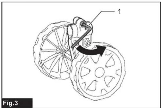
- Loosen the bolt of the wheels with the hex wrench.
▶ Fig.3: 1. Hex wrench
- Align the plate on the pipe with the groove in the wheels, and then attach the wheels to the pipe as shown in the figure. Securely tighten the bolt to fix the wheels.
▶ Fig.4: 1. Pipe 2. Wheel 3. Plate 4. Bolt
NOTICE: Be sure to attach the wheels so that the plate is engaged with the wheels.
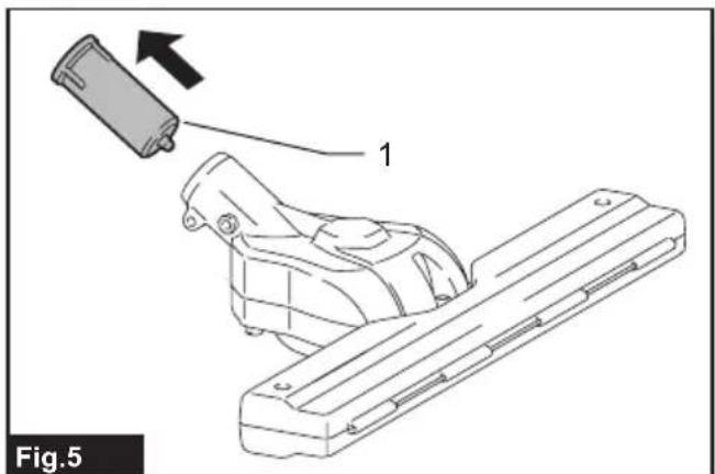
- Remove the cap from the attachment.
▶ Fig.5: 1. Cap
- Attach the attachment to the pipe so that the hole on the pipe is aligned with the hole on the attachment. Securely tighten the short bolt first, and then tighten the long bolt to fix the pipe.
▶ Fig.6: 1. Pipe 2. Bolt (short) 3. Bolt (long)
NOTE: When tightening the bolts, apply 4.0 - 6.0 N•m as tightening torque.
Mounting the attachment pipe
⚠️CAUTION: Always check that the attachment pipe is secured after installation. Improper installation may cause the attachment falling off from the power unit and cause personal injury.
Mount the attachment pipe to the power unit.
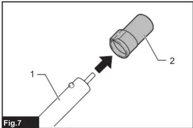
- Remove the cap from the end of the pipe.
▶ Fig.7: 1. Pipe 2. Cap
NOTICE: Do not dispose of the cap since the cap is necessary for storing the attachment.
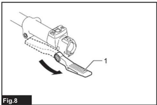
- Turn the lever toward the attachment.
▶ Fig.8: 1. Lever
- Align the pin with the arrow mark on the power unit. Insert the pipe until the release button pops up.
Make sure that the position line is on the tip of the arrow mark on the power unit, and the arrow mark on the power unit and the arrow mark on the pipe are facing each other.
▶ Fig.9: 1. Release button 2. Arrow mark on the power unit 3. Pin 4. Position line 5. Arrow mark on the pipe
- Turn the lever toward the power unit.
▶ Fig.10: 1. Lever
Make sure that the surface of the lever is parallel to the pipe.
NOTICE: Do not tighten the lever without the attachment pipe inserted. Otherwise the lever may tighten the entrance of the drive shaft too much and damage it.
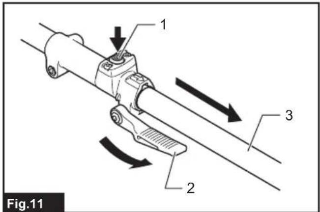
To remove the pipe, turn the lever toward the attachment and pull the pipe out while pressing down the release button.
▶ Fig.11: 1. Release button 2. Lever 3. Pipe
Removing or attaching the blade cover
Release the latches of the blade cover by pulling them, and then open the blade cover.
▶ Fig.12: 1. Latch
When attaching the blade cover to the shear blades, make sure that the blade cover is closed and both latches are fixed securely.
Installing or removing the shear blades
⚠️ CAUTION: When replacing the shear blades, always wear gloves so that your hands do not directly contact the blades.
⚠️ CAUTION: Attach the blade cover before removing or installing the shear blades.
NOTICE: When replacing the shear blades, do not wipe off grease from the crank.
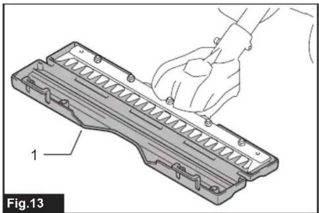
- Place the shear blades on the blade cover.
▶ Fig.13: 1. Blade cover
- Turn the shaft so that the upper blade and lower blade are positioned alternately.
▶ Fig.14: 1. Shaft
-
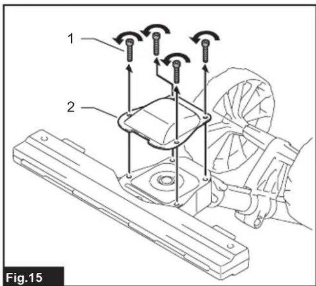
Close the blade cover, and then place the attachment upside down.
-
Remove 4 bolts with the hex wrench and remove the cover.
▶ Fig.15: 1. Bolt 2. Cover
- Remove the shear blades.
▶ Fig.16
- Turn the crank with the slotted screwdriver so that the crank is positioned in the direction as shown in the figure.
▶ Fig.17: 1. Crank
-
Remove the blade cover from the shear blades, and then place the new shear blades on the blade cover.
-
Align the holes of the upper shear blade and lower shear blade as shown in the figure.
▶ Fig.18: 1. Hole
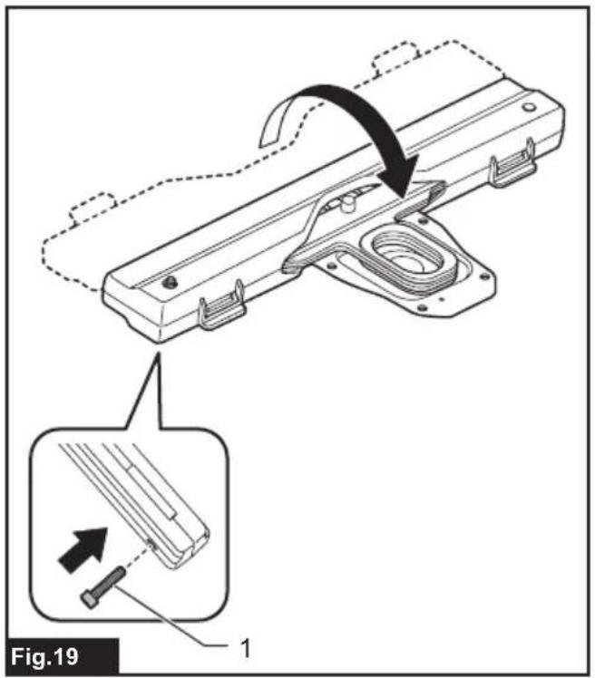
- Close the blade cover, and then insert the bolt removed in step 4 into the hole of the blade cover to temporarily fix the shear blades.
▶ Fig.19: 1. Bolt
-
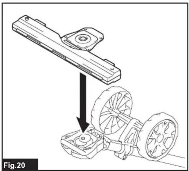
Apply a small amount of grease to the periphery of the crank.
-
Attach the shear blades to the attachment.
▶ Fig.20
- Attach the cover, and then tighten 3 bolts. Remove the bolt inserted into the blade cover in step 9, and then tighten the bolt.
▶ Fig.21: 1. Bolt 2. Cover
NOTICE: If the shear blades do not operate properly, the blades are not engaging the crank properly. Remove the blades and install them again.
NOTICE: If the parts other than the shear blades such as the crank are worn out, ask Makita Authorized Service Centers for parts replacement or repairs.
FUNCTIONAL DESCRIPTION
⚠️CAUTION: Always be sure that the tool is switched off and the battery cartridge is removed before adjusting or checking function on the tool.
Adjusting the cutting angle
⚠️CAUTION: Always be sure that the tool is switched off before adjusting the cutting angle.
The angle of the attachment can be adjusted by changing the position of the wheels. Loosen the bolt on the wheels, then move the wheels to the desired position, and then securely tighten the bolt to fix the wheels.
▶ Fig.22: 1. Wheel
NOTICE: Make sure that the plate on the pipe is engaged with the wheels.
OPERATION
WARNING: Follow the warnings and precautions in the chapter "SAFETY WARNINGS" and the instruction manual of the power unit.
Operating the tool
WARNING: Keep hands away from shear blades.
⚠ WARNING: Be extremely careful to maintain control of the tool at all times. Do not allow the tool to be deflected toward you or anyone in the work vicinity. Failure to keep control of the tool could result in serious injury to the bystander and the operator.
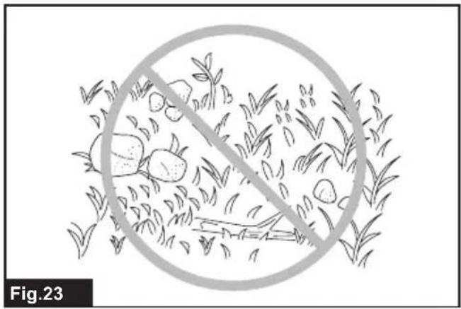
WARNING: Before shearing, clear away sticks and stones from the shearing area.
▶ Fig.23
CAUTION: Avoid operating the tool in very hot weather as much as practicable. When operating the tool, be careful of your physical condition.
CAUTION: Be careful not to accidentally contact a metal fence or other hard objects while trimming. The shear blades may break and cause an injury.
CAUTION: Overreaching with the tool, particularly from a ladder, is extremely dangerous. Do not work while standing on anything wobbly or infirm.
NOTICE: Do not cut down dead trees or similar hard objects. Doing so may damage the tool.
NOTICE: Do not use the tool in a way that causes the motor to stop or to rotate extremely slowly.
NOTICE: Do not attempt to cut thick branches.
NOTICE: Do not allow the shear blades to contact the ground during operation. The blades will be dulled, causing poor performance.
NOTICE: Do not trim the wet grass or foliage of small trees.
Hold the tool with both hands by holding the front handle and the rear grip of the power unit.
▶ Fig.24: 1. Front handle 2. Rear grip
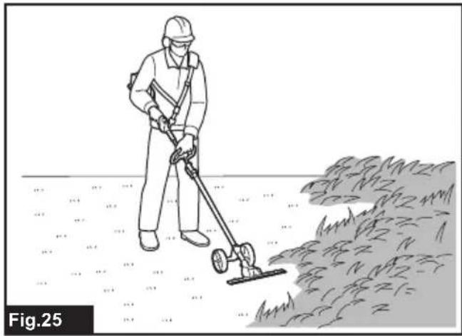
With the wheels in contact with the ground, pull the switch trigger while pressing the lock-off lever, and then move the tool forward.
▶ Fig.25
When trimming around curbs, fences or trees, move the tool along them. Be careful that the blades do not come into contact with them.
MAINTENANCE
WARNING: Before inspecting or maintaining the equipment, switch off the motor and remove the battery cartridge. Otherwise, the machine may start unintentionally and result in serious injury.
WARNING: When inspecting or maintaining the equipment, always put it down. Assembling or adjusting the equipment in an upright position may result in serious injury.
WARNING: Follow the warnings and precautions in the chapter "SAFETY WARNINGS" and the instruction manual of the power unit.
CAUTION: Wear gloves when performing the inspection or maintenance.
NOTICE: Never use gasoline, benzine, thinner, alcohol or the like. Discoloration, deformation or cracks may result.
To maintain product SAFETY and RELIABILITY, repairs, any other maintenance or adjustment should be performed by Makita Authorized or Factory Service Centers, always using Makita replacement parts.
Cleaning the tool
Clean the tool by wiping off dust with a dry cloth or one dipped in soapy water and wrung out.
NOTICE: Never use gasoline, benzine, thinner, alcohol or the like. Discoloration, deformation or cracks may result.
Shear blade maintenance
Before the operation or once per hour during operation, apply low-viscosity oil (machine oil, or spray-type lubricating oil) to the shear blades.
▶ Fig.26
After operation, remove dust from both sides of the shear blades with a wired brush, wipe it off with a cloth and then apply low-viscosity oil (machine oil, or spray-type lubricating oil) to the shear blades.
▶ Fig.27
NOTICE: Do not wash the shear blades in water. Doing so may cause rust or damage to the tool.
NOTICE: Dirt and corrosion cause excessive blade friction and shorten the operating time per battery charge.
Storage
Attach the blade cover to the shear blades so that the blades are not exposed. Store the tool out of the reach of children. Store the tool in a place not exposed to moisture or rain.
When storing the attachment separated from the power unit, put the cap onto the end of the pipe.
▶ Fig.28
Lubricating moving parts
NOTICE: Follow the instruction of the frequency and amount of grease supplied. Otherwise insufficient lubrication may damage moving parts.
Drive axle:
Apply grease (Makita grease N No.2 or equivalent) every 30 hours of operation.
▶ Fig.29
NOTE: Genuine Makita grease may be purchased from your local Makita dealer.
Grease lubrication
Interval of lubrication: Every 50 operating hours
-
Remove the shear blades from the attachment.
-
Apply grease to the inner periphery of the holes on the shear blades (Approximately 1.5 g as a guide).
▶ Fig.30: 1. Hole
- Install the shear blades to the attachment.
Grinding the shear blades
NOTICE: If the shear blades have considerably deformed by grinding, replace the shear blades with new ones.
- Install the battery cartridge to the tool.
- Turn on and start the tool so that the upper blade and lower blade are positioned alternately.
▶ Fig.31 - Turn off the tool and remove the battery cartridge from the tool.
- Set the angle of a file to 45^ , and grind the upper blade from 3 directions with the file.
⚠️ CAUTION: Before grinding the shear blades, make sure that the tool is switched off and the battery cartridge is removed from the tool.
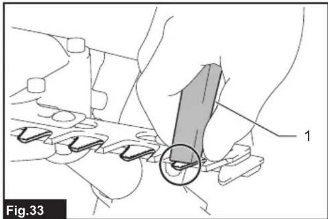
- Place the tool upside down, and then remove the burrs from the shear blades with the dressing stone.
▶ Fig.33: 1. Dressing stone - Set the angle of the file to 45^ , and grind the lower blade from 3 directions with the file.
- Return the tool to normal position, and then remove the burrs from the shear blades with the dressing stone.
TROUBLESHOOTING
Before asking for repairs, conduct your own inspection first. If you find a problem that is not explained in the manual, do not attempt to dismantle the tool. Instead, ask Makita Authorized Service Centers, always using Makita replacement parts for repairs.
| State of abnormality Probable cause | (malfunction) Remedy | |
| Motor does not start. - Refer to the instruction manual of the power unit. | ||
| Motor stops soon. - Refer to the instruction manual of the power unit. | ||
| Motor speed does not increase. - Refer to the instruction manual of the power unit. | ||
| Shear blades do not move: → stop the machine immediately! | Foreign objects are caught between the shear blades. | Switch off the tool and remove the battery cartridge, and then remove the foreign objects using tools such as pliers. |
| The drive system does not work correctly. | Ask your local authorized service center for repair. | |
| Abnormal vibration: → stop the machine immediately! | Shear blades are broken, bent or worn. | Replace the shear blades. |
| The drive system does not work correctly. | Ask your local authorized service center for repair. | |
| Shear blades and motor cannot stop: → Remove the battery immediately! | Electric malfunction. Remove the battery | and ask your local authorized service center for repair. |
OPTIONAL ACCESSORIES
⚠️CAUTION: These accessories or attachments are recommended for use with your Makita machine specified in this manual. The use of any other accessories or attachments might present a risk of injury to persons. Only use accessory or attachment for its stated purpose.
If you need any assistance for more details regarding these accessories, ask your local Makita Service Center.
• Shear blade assembly
• Makita genuine battery and charger
NOTE: Some items in the list may be included in the product package as standard accessories. They may differ from country to country.
SPÉCIFICATIONS
▶ Fig.2: 1. Capuchon 2. Plaque
▶ Fig.4: 1. Tuyau 2. Roue 3. Plaque 4. Boulon
▶ Fig.6: 1. Tuyau 2. Boulon (court) 3. Boulon (long)
▶ Fig.7: 1. Tuyau 2. Capuchon
▶ Fig.17: 1. Manovella
VEILIGHEIDSWAAR- SCHUWINGEN
OPTIONELE ACCESSOIRES
Persona responsible: Hiroshi Tsujimura, Director - Makita Europe N.V.
- hyuunna
▶ Fig.2: 1. Tampa 2. Chapa
▶ Fig.33: 1. Pussestein
▶ Pav.22: 1. Ratukas
▶ Joon.21: 1. Polt 2. Kate
▶ Ábra14: 1. Tengely
TIETO POKYNY USCHOVAJTE.
▶ Obr.22: 1. Koliesko
TYTO POKYNY USCHOVEJTE.

▶ Obr.22: 1. Kolečko
VOLITELNÉ PŘÍSLUŠENSTVÍ
▶ Fig.17: 1. Pârghie
3-11-8, Sumiyoshi-cho,
Anjo, Aichi 446-8502 Japan


- Approved power unit
- Symbols
- Intended use
- EC Declaration of Conformity
- For European countries only
- Declaration of Conformity (For UK)
- For UK only
- SAFETY WARNINGS
- Cordless Grass Shear Safety Warnings
- Additional Safety Instructions
- General instructions
- Personal protective equipment
- Starting up the equipment
- Method of operation
- Cutting Tools
- Maintenance instructions
- SAVE THESE INSTRUCTIONS.
- PARTS DESCRIPTION
- ASSEMBLY
- Assembling the attachment
- Mounting the attachment pipe
- Removing or attaching the blade cover
- Installing or removing the shear blades
- FUNCTIONAL DESCRIPTION
- Adjusting the cutting angle
- OPERATION
- Operating the tool
- MAINTENANCE
- Cleaning the tool
- Shear blade maintenance
- Storage
- Lubricating moving parts
- Drive axle:
- Grease lubrication
- Grinding the shear blades
- TROUBLESHOOTING
- OPTIONAL ACCESSORIES
- VEILIGHEIDSWAAR- SCHUWINGEN
- OPTIONELE ACCESSOIRES
- TIETO POKYNY USCHOVAJTE.
- TYTO POKYNY USCHOVEJTE.
- VOLITELNÉ PŘÍSLUŠENSTVÍ
Brand : MAKITA
Model : EN424MP
Category : Multifunction tool