0 607 450 626 - Screwdriver BOSCH - Free user manual and instructions
Find the device manual for free 0 607 450 626 BOSCH in PDF.
User questions about 0 607 450 626 BOSCH
0 question about this device. Answer the ones you know or ask your own.
Ask a new question about this device
Download the instructions for your Screwdriver in PDF format for free! Find your manual 0 607 450 626 - BOSCH and take your electronic device back in hand. On this page are published all the documents necessary for the use of your device. 0 607 450 626 by BOSCH.
USER MANUAL 0 607 450 626 BOSCH
OBJ BUCH-281-006book Page 1 Friday. September 2, 2016 2:45 PM
Robert Bosch Power Tools GmbH
70538 Stuttgart
GERMANY
www.bosch-pt.com
160992A39P(2014.07)AS/30TUNI

160992A39P
0607450...
...593|...622|...626|...627|...628

BOSCH
OBJ_BUCH-281-006.book Page 4 Friday, September 2, 2016 2:45 PM
4
160992A39P(2.9.16) Bosch Power Tools


6 | Deutsch
Deutsch
OBI_BUCH-281-006.book Page 8 Friday, September 2, 2016 2:45 PM
8 | Deutsch
OBI_BUCH-281-006.book Page 10 Friday, September 2, 2016 2:45 PM
10 | Deutsch
Technische Daten
OBI_BUCH-281-006.book Page 11 Friday, September 2, 2016 2:45 PM

Deutsch | 11
Henk Becker Helmut Heinzelmann Executive Vice President Head of Product Certification Engineering PT/ECS

Robert Bosch Power Tools GmbH
70538 Stuttgart, GERMANY
Stuttgart, 01.01.2017
OBI_BUCH-281-006.book Page 13 Friday, September 2, 2016 2:45 PM


Wartung und Service
The pneumatic tool may not be modified in any way. Modifications can reduce the effectivity of the safety measures and increase the risks for the operator.
Service
Have your pneumatic tool repaired only through a qualified repair person and only using original replacement parts. This will ensure that the safety of the pneumatic tool is maintained.
SafetyWarnings for Pneumatic Impact Wrenches
- Check if the type plate can be read. If required, provide for replacement from the manufacturer.
In case of breakage of the workpiece or an accessory, or even of the pneumatic tool itself, parts can be thrown about at high speed.
During operation, repairs or maintenance, and when replacing accessories on the pneumatic tool, always wear shock-resistant eye protection. The degree of the required protection should be separately evaluated for each individual application. - Never switch the pneumatic tool on while carrying it. Clothing or hair can be caught in a rotating tool holder and lead to injuries.
Wear close-fitting gloves. The flow of compressed air makes the handles of pneumatic tools cold. Warm hands are less sensitive to vibrations. Loose fitting gloves can be caught by rotating parts. - Keep your hands away from the socket drive and the rotating application tool. Never hold a rotating application tool or the drive. You could injure yourself.
Be careful in confined work spaces. Keep hands away from the reaction bar. Reaction torques may result in injuries due to pinching or crushing.
The operators and the maintenance personnel must be physically capable to handle the size, weight and power of the pneumatic tool.
Be prepared for unexpected movements of the pneumatic tool that can develop owing to reaction forces or breakage of the application tool. Maintain a firm grip on the pneumatic tool and position your body and arms to allow you to resist such movements. These precautions can prevent injuries.
Use auxiliary aids to absorb reaction torque, such as a supporting fixture. If this is not possible, use an auxiliary handle.
In case of an interruption of the air supply or reduced operating pressure, switch the pneumatic tool off. Check the operating pressure and start again when the operating pressure is optimal. - When using the pneumatic tool for the performance of work-related activities, the operator may experience unpleasant sensations in the hands, arms, shoulders, neck area or other body parts.
When working with this pneumatic tool, assume a comfortable stance, hold the tool securely and avoid unfavourable positions or such positions, where it is difficult to keep your balance. For prolonged work, the
operator should change the stance or posture, which can help avoid discomfort and fatigue.
Should the operator perceive symptoms such as persistent nausea, discomfort, throbbing, pain, tingling, numbness, burning or stiffness, these warning signs should not be ignored. The operator should notify his employer about the symptoms and consult a qualified physician.
Do not touch any socket drives or accessories during the impact procedure, as this may increase the risk of cutting, burning or injuries caused by vibrations.
Only use impact sockets in good working condition. A defective condition of hand sockets and accessories can cause them to shatter and be ejected when used with impact wrenches.
Use appropriate detectors to determine if utility lines are hidden in the work area or call the local utility company for assistance. Contact with electric lines can lead to fire and electric shock. Damaging a gas line can lead to explosion. Penetrating a water line causes property damage.
Avoid contact with "live" conductors. The pneumatic tool is not insulated; contact with a "live" conductor can lead to an electric shock.
The dust developing during sanding, sawing, grinding, drilling and similar
operations can act carcinogenic, teratogenic or mutagenic. Some of the substances contained in these dusts are: - Lead in lead-based paints and varnishes;
- Crystalline silica in bricks, cement and other masonry work:
- Arsenic and chromate in chemically treated wood. The risk of disease depends on how often you are exposed to these substances. To reduce the risk, you should work only in well ventilated rooms with appropriate protective equipment (e.g. with specially designed respirators that filter out even the smallest dust particles).
Wear ear protectors. Exposure to noise can cause hearing loss.
When working on the workpiece, additional noise can develop, which can be avoided through appropriate measures (e.g. by using damping materials on occurrence of ringing noise from the workpiece).
When the pneumatic tool is equipped with a silencer, always ensure that it is available and in proper working condition when operating the pneumatic tool.
Vibration effects may cause damage to the nerves and blood circulation disorders in the hands and arms.
If you notice that the skin of your fingers or hands becomes numb, tingles, hurts or turns white, stop working with the pneumatic tool, notify your employer and consult a physician.
Do not use worn or poorly fitting socket drives and extensions. This can lead to intensification of vibrations.
If possible, use a stand, spring pull/balancer or compensation device in order to support the weight of the pneumatic tool.
English|17
Hold the pneumatic tool with a not too firm yet secure grip, compliant with the required hand-reaction forces. The vibrations can be intensified the firmer you hold the tool.
When universal rotary couplings (bayonet couplings) are being used, retaining pins are required. Use Whip-check hose restraints to protect against failed hose connections or the connection between hose and pneumatic tool.
Never carry the pneumatic tool by the hose.
Support the screwdriver with, for example, a reaction bar when you are working at high torque. Work at high torques may result in damaging reaction torques, which can be reduced by using a support device.
If you want to operate the pneumatic tool in a suspension device or a clamping fixture, take care to fasten it in the device/fixture first before connecting it to the air supply. This measure prevents accidental starting of operation.
Symbols
The following symbols could have a meaning for the use of your pneumatic tool. Please take note of the symbols and their meaning. The correct interpretation of the symbols will help you to use the pneumatic tool in a better and safer manner.

Before installing, operating, repairing, maintaining and replacing accessories as well as prior to working near by the pneumatic tool, please read and observe all instructions. Failure to follow the following safety warnings and instructions may result in serious injury.

Always wear ear protection.

Wear safety glasses/goggles
Symbol Meaning
| W | W | a | t | t | P | o |
| Nm Newton metre | Unit of energy (torque) | |||||
| kg | Kilogram | Mass, weight | ||||
| Ibs | Pounds | |||||
| mm Millimetre Length | ||||||
| min | Minutes | Time period, dura- | ||||
| s | Seconds | tion | ||||
| min-1 | Revolutions or motions per minute | No-load speed | ||||
| bar | bar | Air pressure | ||||
| psi | pounds per square inch | |||||
| Symbol | Meaning | |
| l/s | Litres per second | Air consumption |
| cfm | cubic feet/minute | |
| dB Decibel | Unit of relative loudness | |
QC Quick-change chuck
Symbol for hexagon socket
Symbol for external drive Tool holder UNF US fine thread (Unified National Fine Thread Series)
G Whitworth thread NPT National pipe thread Connecting thread
R
Right rotation
L
Left rotation
Product Description and Specifications
Read all safety warnings and all instructions. Failure to follow the warnings and instructions may result in electric shock, fire and/or serious injury.
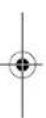
While reading the operating instructions, unfold the fold-out page with the illustration of the pneumatic tool and leave it open.
Intended Use
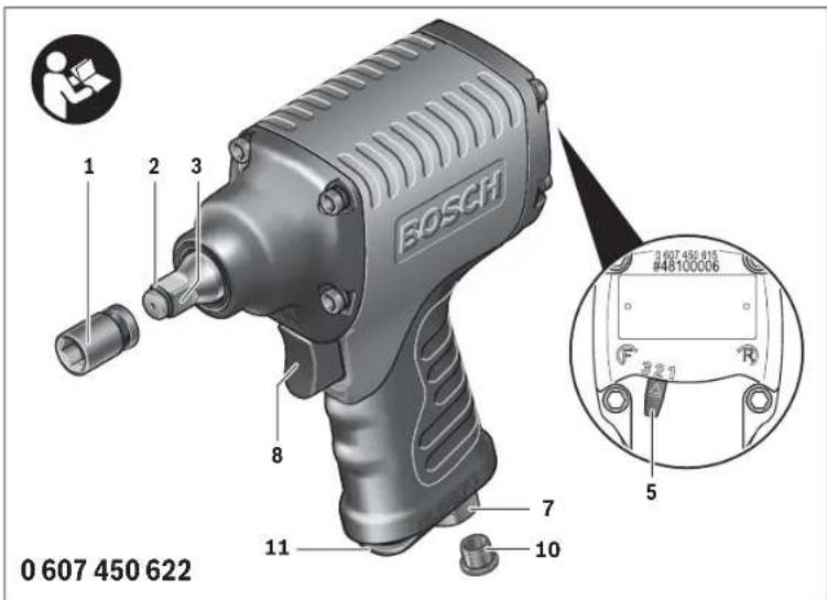
The pneumatic tool is intended for driving in and loosening screws as well as for tightening and loosening nuts within the given dimension and power range.
Product Features
The numbering of the product features refers to the illustrations on the graphics page. The illustrations are partly schematic and may differ from your pneumatic toq).
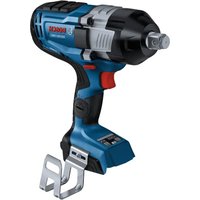
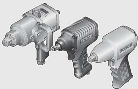
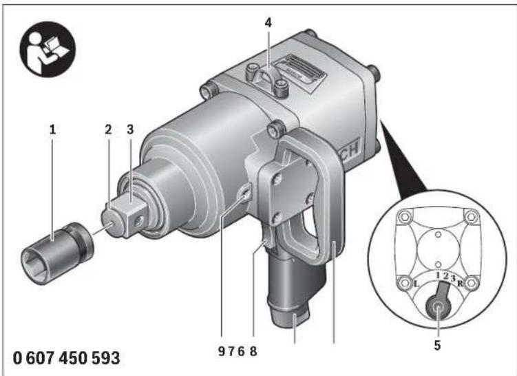
1 Tool bit (e.g. impact socket for hexagon bolts according to DIN 3129)
2 Snap ring on the tool holder
3 Tool holder
4 Suspension hook
5 Rotational direction switch
6 Auxiliary handle
7 Connection thread at air inlet
8 On/Off switch
9 Locking screw
10 Closing cap
11 Air outlet with silencer


OBI_BUCH-281-006.book Page 18 Friday, September 2, 2016 2:45 PM
18|English
12 Screwdriving
13 Washers
14 Utility clip
15 Hose fitting
16 Hose clamp
17 Supply-air hose
18 Tube connector
19 Clutch
20 Oil chamber
The accessories illustrated or described are not included as standard delivery.
Technical Data
| Pneumatic Impact Wrench | ||||||
| Article number 0 607 450 ... | ...593 | ...622 | ...626 | ...627 | ...628 | |
| No-load speed n0 | min-1 | 3100 | 4500 | 10000 | 10000 | 7000 |
| Maximum torque according to ISO 5393rotated right | Nm | 1300 | 900 | 120 | 120 | 310 |
| Max. screw dia. | mm | 33 | 27 | 14 | 14 | 18 |
| Tool holder | ■1" | ■3/4" | ■3/8" | ■1/2" | ■1/2" | |
| Engine oil SAE 40 | ml | 25 | 40 | 15 | 15 | 25 |
| Max. working pressure for tool | bar | 6.3 | 6.3 | 6.3 | 6.3 | |
| psi | 91 | 91 | 91 | 91 | ||
| Thread size of hose connection | G1/2" | 3/8" NPT | 1/4" NPT | 1/4" NPT | 1/4" NPT | |
| Inner diameter of hose | mm | 13 | 13 | 10 | 10 | |
| Air consumption at no-load | l/s | 13 | 18 | 6.0 | 6.0 | |
| cfm | 27.5 | 38.1 | 12.7 | 12.7 | ||
| Weight according to EPTA-Procedure 01:2014 | kg | 9.6 | 5.6 | 1.5 | 1.5 | |
| lbs | 21.2 | 12.3 | 3.3 | 3.3 | ||
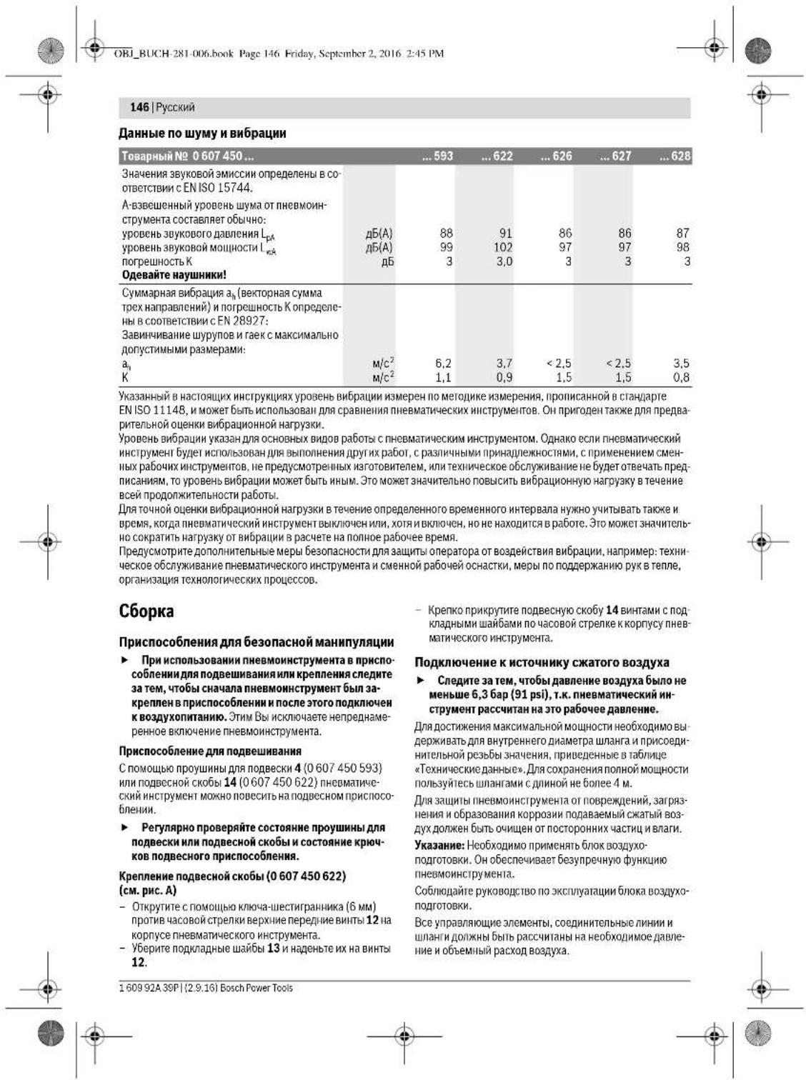
Noise/Vibration Information
| Article number 0 607 450 ... | ...593 | ...622 | ...626 | ...627 | ...628 | |
| Sound emission values determined according to EN ISO 15744. | ||||||
| Typically the A-weighted noise level of the pneumatic tool is: | ||||||
| Sound pressure level LpA | dB(A) | 88 | 91 | 86 | 86 | 87 |
| Sound power level LwA | dB(A) | 99 | 102 | 97 | 97 | 98 |
| Uncertainty k | dB | 3 | 3.0 | 3 | 3 | 3 |
| Wear hearing protection! | ||||||
| Vibration total values a, (triax vector sum) and uncertainty K determined according to EN 28927: | ||||||
| Tightening of bolts and nuts of the maximum permitted size: | ||||||
| a, | m/s2 | 6.2 | 3.7 | <2.5 | <2.5 | 3.5 |
| K | m/s2 | 1.1 | 0.9 | 1.5 | 1.5 | 0.8 |
The vibration emission level given in this information sheet has been measured in accordance with a standardised test given in EN ISO 11148 and may be used to compare one pneumatic tool with another. It may be used for a preliminary assessment of exposure.
The declared vibration emission level represents the main applications of the pneumatic tool. However if the pneumatic tool is used for different applications, with different accessories or insertion tools or is poorly maintained, the vibration emission may differ. This may significantly increase the exposure level over the total working period.
An exact estimation of the level of exposure to vibration should also take into account the times when the pneumatic tool is switched off or when it is running but not actually doing the job. This may significantly reduce the exposure level over the total working period.
Identify additional safety measures to protect the operator from the effects of vibration such as: maintaining the pneumatic tool and the accessories, keeping the hands warm, organisation of work patterns.


OBI_BUCH-281-006.book Page 19 Friday, September 2, 2016 2:45 PM
English|19
Declaration of Conformity C We declare under our sole responsibility that the product described under "Technical data" complies with all applicable provisions of the directive 2006/42/EC including its amendments and is in conformity with the following standards: EN ISO 11148-6.
Technical file (2006/42/EC) at: Robert Bosch Power Tools GmbH, PT/ECS, 70538 Stuttgart, GERMANY
Henk Becker Helmut Heinzelmann Executive Vice President Head of Product Certification Engineering PT/ECS

Robert Bosch Power Tools GmbH
70538 Stuttgart, GERMANY
Stuttgart, 01.01.2017
Observe the operating instructions of the maintenance unit. All fittings, connecting lines and hoses must be dimensioned for the pressure and the required air volume. Avoid restrictions in the air supply, e.g., from pinching, kinking, or stretching! When in doubt, check the pressure at the air inlet with a pressure gauge with the pneumatic tool switched on.
Connecting the Air Supply to the Pneumatic Tool Note: Always mount the supply-air hose to the pneumatic tool first, then to the maintenance unit.
0607450593 (see figure B)
- Remove the closing cap 10 from the connection thread at the air inlet 7.
- Screw a hose fitting 15 into the connection thread at the air inlet 7. To avoid damage to interior valve components of the pneumatic tool when screwing the hose fitting 15 in or out, it is recommended to counter-hold the projecting connection thread at the air inlet 7 with an open-end wrench (size 26 mm).
- Loosen hose clamp 16 of supply-air hose 17, mount the supply air hose to hose fitting 15 and retighten the hose clamp.
0607450622/..626/..627/..628 (see figure C)
- Remove the closing cap 10 from the connection thread at the air inlet 7.
- Screw a tube connector 18 into the connection thread at air inlet 7. To avoid damage to interior valve components of the pneumatic tool when screwing the tube connector 18 in or out, it is recommended to counter-hold the projecting connection thread at air inlet 7 with an open-end wrench (size 22 mm).
- Place the supply-air hose 17 with the appropriate clutch 19 onto the tube connector 18.
Assembly
Devices for Safe Handling
If you want to operate the pneumatic tool in a suspension device or a clamping fixture, take care to fasten it in the device/fixture first before connecting it to the air supply. This measure prevents accidental starting of operation.
Suspension Device
You can fasten the pneumatic tool to a suspension device using the suspension hook 4 (0 607 450 593) or the utility clip 14 (0 607 450 622).
Regularly check the condition of the suspension hook or the utility clip and the hook in the suspension device.
Fastening the Utility Clip (0607450622) (see figure A)
- Screw the upper, front screws 12 with an Allen key (6 mm) in an anticlockwise direction from the housing of the pneumatic tool.
- Remove the washers 13 and place them onto the screws 12.
- Firmly screw the utility clip 14 with the screws and washers in a clockwise direction on the housing of the pneumatic tool.
Connecting the Air Supply
Ensure that the air pressure is not lower than 6,3 bar (91 psi) because the pneumatic tool is designed for this operating pressure.
For maximum performance, the values for the inner hose diameter as well as the connection threads must be adhered to as listed in the "Technical Data" Table. To maintain the full performance, only use hoses with a maximum length of 4m . The compressed air supplied should be free of foreign material and moisture to protect the tool from damage, contamination, and the formation of rust.
Note: The use of a compressed-air maintenance unit is necessary. This ensures proper function of the pneumatic tools.
Changing the Tool
- Disconnect the air supply before making any adjustments, changing accessories, or placing the pneumatic tool aside. This safety measure prevents accidental starting of the pneumatic tool.
When working with an application tool, pay attention that the application tool is firmly seated on the tool holder. When the application tool is not firmly connected with the tool holder, it can come loose again and not be controlled.
Inserting
- Slide the application tool 1 over the square drive of the tool holder 3. Pay attention that the snap ring 2 locks in the groove of the application tool. Use only application tools with an appropriate shank end (see "Technical Data").
Do not use adapters.
Removing
- Pull off the application tool 1 from the tool holder 3. A seized application tool can be loosened by applying light blows with a rubber hammer.
Bosch Power Tools 1609 924 39P(2.9.16)


Français
OBI_BUCH-281-006.book Page 26 Friday, September 2, 2016 2:45 PM
26 | Français
Symbol Signification
OBI_BUCH-281-006.book Page 34 Monday, September 5, 2016 12:19 PM
34|Espanol
OBI_BUCH-281-006.book Page 42 Friday, September 2, 2016 2:45 PM
42 | Português
Simbolo Significado
E

Marcha à direita
Sentido de rotação
1
Marcha à esquerda
OBI_BUCH-281-006.book Page 43 Friday, September 2, 2016 2:45 PM
Portugues 43
Executive Vice President Head of Product Certification
Engineering PT/ECS

Robert Bosch Power Tools GmbH
70538 Stuttgart,GERMANY
Stuttgart, 01.01.2017
Montagem
OBI_BUCH-281-006.book Page 51 Friday, September 2, 2016 2:45 PM
Italiano | 51
Dati tecnici
OBI_BUCH-281-006.book Page 53 Friday, September 2, 2016 2:45 PM
Italiano | 53
OBI_BUCH-281-006.book Page 59 Friday, September 2, 2016 2:45 PM
Nederlands|59
Symbol Betekenis
QC Snelwisselhouder
OBI_BUCH-281-006.book Page 60 Friday, September 2, 2016 2:45 PM
60|Nederlands
Executive Vice President Head of Product Certification
Engineering

Robert Bosch Power Tools GmbH
70538 Stuttgart,GERMANY
Stuttgart, 01.01.2017
Montage
OBI_BUCH-281-006.book Page 68 Friday, September 2, 2016 2:45 PM
68|Dansk
Overensstemmelseserklaering
Executive Vice President Engineering
Helmut Heinzelmann
Head of Product Certification PT/ECS

Robert Bosch Power Tools GmbH
70538 Stuttgart,GERMANY
Stuttgart, 01.01.2017
Montering
OBI_BUCH-281-006.book Page 70 Friday, September 2, 2016 2:45 PM
70|Dansk
0607450593 (se Fig. D)
OBI_BUCH-281-006.book Page 73 Friday, September 2, 2016 2:45 PM
Svenska 73
OBI_BUCH-281-006.book Page 75 Friday, September 2, 2016 2:45 PM


Forsakran om overensstammelse C
Henk Becker Helmut Heinzelmann Executive Vice President Head of Product Certification Engineering PT/ECS

Robert Bosch Power Tools GmbH
70538 Stuttgart, GERMANY
Stuttgart, 01.01.2017
Montage
Utrustning for sakerHantering
OBI_BUCH-281-006.book Page 77 Friday, September 2, 2016 2:45 PM

Svenska 77
OBI_BUCH-281-006.book Page 79 Friday, September 2, 2016 2:45 PM
Norsk|79
OBI_BUCH-281-006.book Page 80 Friday, September 2, 2016 2:45 PM
80|Norsk
| Symbol for untendig faktant | Verkleyfeste | |
| UNF | US-fingjenger( Unified National Fine Thread Series) | |
| G | Whitworth-gienger | Tilkopingsjenger |
| NPT | National pipe thread | |
R

Hoyregang
L

Venstregang
Produkt- ogytelsesbeskrivelse

OBI_BUCH-281-006.book Page 82 Friday, September 2, 2016 2:45 PM
82|Norsk
Samsvarserklaering
C
Executive Vice President Engineering
Head of Product Certification PT/ECS

i. V.k = W_C
Robert Bosch Power Tools GmbH
70538 Stuttgart,GERMANY
Stuttgart, 01.01.2017
Montering
Utstyr for sikker handtering
OBI_BUCH-281-006.book Page 86 Friday, September 2, 2016 2:45 PM
86 Suomi
OBI_BUCH-281-006.book Page 87 Friday, September 2, 2016 2:45 PM
OBI_BUCH-281-006.book Page 88 Friday, September 2, 2016 2:45 PM
88 Suomi
OBI_BUCH-281-006.book Page 89 Friday, September 2, 2016 2:45 PM
Suomi | 89
Executive Vice President Engineering
Head of Product Certification PT/ECS

Robert Bosch Power Tools GmbH
70538 Stuttgart,GERMANY 70538 Sturtegut,Germany
Stuttgart, 01.01.2017
Asennus
OBI_BUCH-281-006.book Page 91 Friday, September 2, 2016 2:45 PM
Suomi|91
OBI_BUCH-281-006.book Page 93 Friday, September 2, 2016 2:45 PM
EANyivk@93
Mny xpnoonouone eva copyaleio memcavou aepa ato v ON/OFF daokntc tou civa xalaovoc. Eva copyaleio memcayou aepa tou dev mopel va teoi mev oe leatopyla nextoc,leituyia elvat enkivuvo kai pemei va cienkeuaotie.
Na diakotene nvtote mytpooodoe aepa npv b
cayctc ot ouokcn kana cypia opuhuc, crav
poketai va aalee cepapnti ha vay tn pnpno
ouie yau nou kaip. Autro to paoanikmo ptoe epono
keyntn ae anen enkniou tou epyaalou meeqevou ae
pa.
Na anoohkeute/biaupukayere ta epyalea nemeieoue vaoce oxipov ampoatouc ne naio. Mny emptoe ce npnoaounv ou civ eviaekowcuva ie to epyaleo nemeuevou aepi hevxoyu diaeaicnapooae onyilec va xnpoonotouou to epyaleo nemeieoue vao. To epyalea nemeuevou aepi civ enkivduva orav xnpoonotouvra anre aepu npoaos.
Na nepunoiote emueo, ta cypaeia tne meouevou aepa. Na bejaiweote oia daa tv kivoueva eapnjuata TNC uocukei Iactauoyou apiaata Kai 6ev gnpovouk Kaos kai ot bEv exouymaei xahdooe kmoia Eapjura, ootetra v ampeodctat avopriukia Iactauoyla Tou cypaeiciou nmeceuvou aepa. Na divete ra xalaqveApEupayuIepuaTVAIcKINpovipxnpouoje To epyaleo nmeepouv aepa. Hekimuc auvtipan Tuv epayakeiu wneepouv aepa amoreel amia nookav atuyntu
Na xpaiaoioieTo epyaleio nmeouov aepa, ta
eaptnjnta, ta epyaleia kai. ouipwau ma TC npaooec
oyicke. SumlAnpoatka va laupve entu ong ackai
tck ekatate uuvthekc epyaaac kai tyu no EKTEAeien
eypaia. Etai nepiopciVai kato duvato ndyiupyoi
okovic, o kpaobaoi kai kkrnnn BpuiBau.
To epyaelo nenieoevou aepa npnei va ovapuoloyn oei, va puoiotei ka va xnpouonoeir anokAciotka anot kato AAnAo ckiakoevuo npnooik.
Ev enpenceta n pematom tou epaaleou nemeoue ou aepa. Tuoyu patpmoc meopel va eattauou tvn amoteeaatikotrau Tou ptpaw apakaleac kai va auou coukov kivouc yia tokeipatn.
Service
Na 1e oepaleo aepoc yia mkeun ano apota cnaevo eiko npooomko kai yvnoa vnt alakta. Toei eaoaicte Tn diatponan Tc aoaeiac Tou epaloe aepoc.
Yno6eiic aaoaaleiac yia kpooutka Kartaibia nmeaeqvou aepa (muoulovokke)
BcBaioeire on nivakiao rua kaoaKauaot civa cuayawvmo. Avpcaeotnnoi rou kaiokauon mai Kaivouipnuikia.
neptwnanpaoangtou unokepyaola teayiou, evoc eapntatocn kakn kai tou iou tou epaclou nemeovou npoepi taopaa va ekoevoivotou mv ceyAn Toxunina.
*Tav epyaeate Kabi Ka Tav eneouae, auynpeite, n avtkaotatc eapntaatau cypaiaocnncpeovau npape na vpoatae t a jaac na nvoote anoteaeapartka e katalaaalediarefe.0baoPoc noptaoiae npene va kxtjaiatkexwipota tvn exoktoe uno kctkeon cypaiae.
MgOeTe to cyaleio aoc note aeIcToupyia, oav to jeaepede. H nepatpeooyevn unboxeyceyaiou mpoel va tuaxtela oaaia na ta poya aac kai va onnyoei otov pauamogaoac.
Naopatecpapnoa yavta. Oaabeuwepayaiwn neimaeuvoaepayovtiaefaricou peuotoc aepo. Oraiv ta xepia civa cera avexcvn nepaoorepo oouc kpa daouc. Paoiayva nupoei va eunakov stnepepuevaetapmuata.
Na npopuayetye ta xepia oac amo tic unoboxc taw oAanwauk kkeiouki ame nepiortpeoejeva epyaleia. Mny npoonaohote note va nioote to nepiortpeoejevo epyaeio hto mxaivao kivnong.Mnpoei va rpaunatoreirc.
Na pooeexetotavepayoeoteoctveceocNa kpa-ta xepia aagpki an no tduankovtpapiaToc. EaIarL Taw eipawovavvntopawonovtpeun mcpol vopaumane an oohywnou Cohnya
OeiprtnK kTpoopmuk oovrnpnc npenei va clv ae 0eon v avtaneEcpovnto oeoc, to bapoc ka TIV axu To pvceAioenmeqcvou aepa.
Na unoloyicne novtoe me avanvtexec kvioec tou eyaiaoumeieqevou aepo rou mnpovv u npokAn Boov an khotanjai n ao paoon rou eyaiaiou. Na KpOte To eyaiaole meieqevou aepo yap Ka va malpvte Me to owaac Ka ta xepaac thec otc onoe 0 npoeocve AvtaneEhctere cKnuoeic autc.Aura Ta npolnntka eipora oujbalauov any npoata oia anpuaopuocv.
Na xpaonpooneiEponnmaTAYaTN eousetepoan TAWpomovorpeyn,π.xμa6daTn anpIeN. OraV auto dev evai epkto va xpaonpoonei pa npooBte NaaB
OeTe Ta epyaleo nemoeou aepa Ektoe Aetoupylac otav dakoen i npoxn nmeocueyou aepa hotnv neoei nneon Aetoupyiac. EaeE rny nien kntoupyac kai Ekvihote ma pe ty oivkiin meon Aetoupylac.
KataTnV exTeAen TnV stapov apv epyaav me toepa Aeio nmeaeuov aepo a xeiptic tou copaaleou nem eevou aepa npoei va oanovc biapopa duapeota auimutata strxepia ta npatrao, tou wouoc n ae AA JEPn Tou aupatoc Tou.
Orav cyapocre mc auto to epyaleio nemeouaepa va maipveo ma avetn kai oopaaanrstan kai va anopeuyete kthe duayevn thepyaacn theeic otolec elva 6dokovo daatnpoeet neu wopponaoc. Karatn dapkeca epyaow ucyawnc diapkeiac o xeiipntgnapeena va aAaeTn raoan tou oupatoc tou.Auto oubetale stny amopuyh guadpeotw oumuutawkai TNCKOpauanc.


94|EAnvka
Oxepiunc6v npievi aodopopoei otav 0a oaoav- cvi noAol npia oaiia aalec diarapaxc, ioxpocnaoicnovouc,knpo,kayipata hdookupia, aa npievi to avokoioteoT ov epyobtou kai va oupouleurei evav ciokoyatp.
Mny aayle ta kajla undoxy h kaveva eeptna kata tn diapkeia tnc daekuaic nK pOvoNC, cneiH auto mpe va auoei rov kivou konc, ykauatoC npauatapoo dov tv KpObaqua.
XpnaomoeiTe anokaeotka unooboxc kpoanc (kapu- dka) oe kaai katotaen epaiaoc, Mia eakwpatriki katoanaun wu onoboxw kau vekaptnaun mnpoe va oynjaoic oepaian kai ny cxtivaen tou kata npnnc paokoutia katoaibia (muouovokAea).
Xpouonouocite katalanac avxveutke ouokceuc yva evotriae tuxov m opatec trooobotke youpieh c ouoouelurete tyu tonuk emeylenop omoohc evepueuc. H enaqn ie nektripke youpiec umoei va onnyhoei oe npukayia kai naektoponmHa. Tuyov Abin evoc ayouou acipoi (ykaiaoui) umoei va npokalcoe ekpnj. To pumuaev ocupooaahv npokakai ulikne jnauec.
Na anopoeuyte nyn eapn ie ncktpoopouc ayovoc. To eayale meeepoyou aede dev elvat mvoovevko i enpaoi ie evay nkeptropoopo ayawo omuoe vi oynyoe ce naekponiaqia.
NPOEIOTIOIHEN
Hokovnou napayetakata m
npovjua, to pumna kaoa kai kata nTv ektean npoauov eyaow mopel va elvakapkoyovoc,vaAemr T yovmuT a vaeBaaT o teyeku uko.Mepka anoTuuknounepeixovtaOautec ticokoece elvai.
-MoAuboc oμoAubouxaoguata kaiakc.
- KpuoTAAaIK npuRikn YN oC NIAOUC,TOJEVTOK OALOC AAMUKA ToXIOJIAC.
-apeviko kai xpawarivn oe xynikkatapeyaogevo Eilo.
O klovuoc voanongc eapataoi and noaouyk estetaiar kaioo cta uikiauto. Ia va nepiopioe tov klovuov ba npe nei va epycaote oe kaiaeipouevouxupoiak va qopate avayoloo npotatutukic eoionlioj (I, x, mc iobka kataaekuaqieve, avavwauitkeuc ooiotole auykpatoivokn kai ta miko pukoiad oovki.
P OpiacraaioeC. Hcipaaon Tou Bpuou npoei va oeyaiy e an aieae Tnckock
OraV KATEpyaceTe Ta diapopa UaKa ioc napaxthetaoepBnnyeamepabvyn, n oIola, dmuac, npoei va KaTanaoleupei eAunKataaAnawpEtpwv, x.xpnOauonouovovovovuAaOavTo uno KATEpyoia Teuxo napayei petaaAkoic fioue.
一 T r a v 以 e p y a l e 念 国 业 国 国 国 国 国 国 国 国 国 国 国 国 国 国 国 国 国 ~ t ~ o ~ ~ i ~ ~ a ~ ~ t ~ a ~ ~ t ~ a ~ ~ p ~ a ~ ~ c ~ ~ t ~ e ~ ~ t ~ o ~ ~ t ~ o ~ ~ t ~ a ~ ~ t ~ a ~ ~ p ~ a ~ ~ c ~ ~ t ~ e ~ ~ t ~ o ~ ~ t ~ o ~ ~ t ~ a ~ ~ t ~ a ~ ~ c ~ ~ t ~ e ~ ~ t ~ o ~ ~ t ~ o ~ ~ t ~ a ~ ~ t ~ a ~ ~ c ~ ~ t ~ e ~ ~ t ~ o ~ ~ t ~ a ~ ~ t ~ a ~ ~ c ~ ~ t ~ e ~ ~ t ~ o ~ ~ t ~ a ~ ~ t ~ a ~ ~ c ~ ~ t ~ e ~ ~ t ~ o ~
H Kpaapol umepol va baoouva veopa ka va npokaaov avwajie ctnv kkaopopla tou alatoc e paia ka mpatra.
*OTav damotowae ot ta 6epa Tuav daxtuauo aoc n Tuv xepuac muaiaea, napouaoae uuprrnata Knojoo, novoei ampoe, tote biokoye tvv eya
oi aoc, eioonoiote tv epyobotn oac kalouuoueute eva yarpó.
Mnyxnpouponouocte qapuevec n anakpbcic unofo xek kai emukovoe. Mnopei va auonbov ou kpa6aaojoi.
Fua va eoubepeoote to apoc tou epyaleiou neme ouevou aepa xpanayomoihtoe,av auto elva epuok, evav opooatn, eva naayakk n ma daataqnvippononc.
Mny kparate to cpyaio nemcavou aepo nol oopKa, aaAoapKc ka va AapBave TmOwoc tcvatiooxe anapainTcavbipocTcw xepowoc. Okaabaqol umoei evayubodov avakoyae to opfioou nou epoipocTe 0r epyaleo nenoeou oepa.
Tavx npaumoieTe yupotouc ouv6etpec yevukx xphoc (ouv6tpec me ydvto) penevi ta vmo taeohoeTc kai nipoc oapalac. Na xhpauonoei aopafalec eowlya tmou Whipecheck. Era Eaapaliovrai ka on ouv6eic, wovawuwv me to eoyaleo nemieqevou aepa Ka iouv6eae cetafo wovawuwv.
MvIeptapeTe note toepaIeIo nenieqevou ape KpOgivac oAo oAlyva.
Na unoortnlcte to mouovokla6o, n.x. kpatwntac Kovtpa me ia kalanaih dtaatn, dravc opece me uynai nont opetnc. O'art cyopcaocte me uynai cpcne, otepueic niopoei va dpaoov anvpiuke ic vioaatake duvcmu (kaotalata), o tiolec, mauc, mupov va piaowu me TnBohdieia mka catraanlnc dtaenrnoonphtncc
OraV eAeTe va epyaTeIe Me To epyaTeio aepoc kavoTACX npnnaucuauagaptnncn uwoqipnc, Tore npeneva to atepoeote anu taun auyn npnu to uvoBaeTe any npoabotnnepe. EToanopoeeyte nky kata ldooekivnoiou
UuBoa
Ta ouijola nou akolouov mopei va exou anlaia y ta eaycdoac me nncievo aepa. Napakaiue amorunoe cte 0ra uaiao na Ta auijba kai Tn anjaou tauc.H aoatn epnuvela tuv ouipkawuupdaleoavkauteko aopaeotepo xeiapauotepyaieoi me nmeqveo aepa.
Σμβολ Σμαδι

Tpvnyeykarataoan,tnleitoupyia,Tnv enoeku,ntuvtnonkai Nvyavtataaenaptnauw, kaoacnpiivapxlaeotevpeyaceotcvraTTOvpeAeNnequeVuaepaaeaeKauTVPnactoealencunobieec,HnapaOnTuvnoiueEevooaagaaelacou nokakakououmupeilvexouwamteelaouo aoaopaocpaatauouc.

OBI_BUCH-281-006.book Page 95 Friday, September 2, 2016 2:45 PM

Epo

Dopoe npooraunka yuaia
| W | W | a | t | t | I |
| Nm Newtonmeter | Movába evcpeyicac(Ponm strpěvné) | ||||
| kg | Xuδyραμμo [kαδ] | Maζα, βδρος |
| Ibs | Pounds |
| mm Xiliogro Mhiko |
Xpnooupuwauerovtnpoepa
To cypaiaio aepoc noopoei cra i yoi Bida kai To Auaio Bidov kaioi kai yoi aipieo kai To Auaio naiaiaow otny avaoepcev neipoxh biadaiotaoavk aoixouc.
Anekoivoeva otoxieia
HanapibunonTuw aenikovizoeuvw otoxieiw avapeptai otic aneiokovicacn oiaoiae je ta vapakia. Oopaevec anekovicioc elvaayamiek kai mepal ve diaqepouv an ekeivc tou eayoleu neneqvou aepa.
1 Epyaleo (napeAekovne) (x. xavoei kaeidoi ouqovva me to npotroDIN 3129 ia [bce6 me eefovnu kepa]
2 P6eHa aqaaieac oyn unofoy ncpyaiaou
3YnOboXyepyAeiou
4Iopnnavapntnnc
5Aakotnc,akayn,phiac,neiptoopn
6Pioo0eemla3h
7Ieipwua ouv6cnc ony eioofo rou aepa
8 Dαkòntnc ON/OFF
9 Biodro mpa
10 Biwto mua
11'Eoocepocc ooyanip
12Bibec
13 PoeAe
14 Toe avaptnang
15PaKop oAAnva
16 Σφγκτηρας ωλλνα
17 ZIyvac Tpoopodomnpeepa
18 Trpoicukainou
19∑μmλκτης
20 Dαμος λδιού
EApHnATA NO AnekovovtA nepyipovotA dev nepiXovTAt ot stTATO uokvukA.


OBI_BUCH-281-006.book Page 96 Friday, September 2, 2016 2:45 PM
96|EAnvka
Texvika xapaktnpotiuka
IIAnpoopoeic yia opuo KaI doynoeic
OBI_BUCH-281-006.book Page 97 Friday, September 2, 2016 2:45 PM
EAnynk@97
Anwoupaepe aokaiatn paac eunv, on to npov nou npapepetra oTg Teykia otoyiaavntaoe ie dce toc xekic Guaie cnc 2006/42/EK oumepaabayoeuvw vaw alkyov nC kai turtetra pa taakoloua npotura: EN ISO 11148-6.
Teyukiok fkekaoc (2006/42/EK) ano: Robert Bosch Power Tools GmbH, PT/ECS, 70538 Stuttgart, GERMANY
Henk Becker Helmut Heinzelmann Executive Vice President Head of Product Certification Engineering PT/ECS

Robert Bosch Power Tools GmbH
70538 Stuttgart, GERMANY
Stuttgart, 01.01.2017
O eioeocvoc aepoc npenei va mny nepiey Eevavntkicuva Kau ypaola, yia va npodaturel to epaela aepoc an o njeic, Bpauei c o aeoioei.
Ynueo:Anaenrataonxionu mucovadoc uovnepn. Etoe eoaeoketai n apoiot Aetoupiyaou ty oevaaou aoepc.
Aaote npoooh ntioc oyniece xepiaou tnc povadac ouvtanon
Oloi oonmouo, o ypaumoc ouvebeoc kai otawhyce npenei vaotexouov tny nien kai stov anapaimtro oyko aepoc.
AnopoeYTEcTNEeWcE TO TPOD0TeKwVyOaMv, P. x. anQuaHauTae,TaekiaTuTnTvTuMa?
AvxpeaoiTe, eAeyTe nyn meo anmny eo0o aepoc me eva mavo- meipo, oav to cypaleio aepoc bioket ae leoupyia.
Uv6ean TnTPOPOOlae aepoc 0To epaaleo aepoc
Nyoedcn:Na ORepeoeWte oouyna npoxh eapoc npwa
0To epaaleo aepoc kai katim ot movoda uovthonqn.
0607455093 (Baeene Ekeova B)
Anapakvcre tny rana 4pync10 amo to oceipua ouv6e onc anr elaofo tou aede 7.
Biaoei eae aoe iocauimou oawlya 15 0ra oineipua ouvebocn 0my elaofo ou cepa7.
Tn anopuy (njaac sta eawepika eupakokoevaue pueon Tc baikbactoayekolne meneevou oape, npene kata To bijua kai To xibijua taou taotou Eukapmou oavuva 15 tropoefov anelipua atuvvEong Tc eio6ou ta epe 7 va kovtapapte me eva yepavko kkei (avojuka KkiDIO 26 mm).
-XaIApawOTe TOU aOpivKTpec 16 TOU aLHVa npaohy cAepoc 17 KAI ePeOwTe To aOLHVa npaohy cAepoc eravv sto pKap oLHVya 15, apoyovta To opaiyTpaolva.
0607450622/..626/..627/..628(βλeineikovαC)
Anapuayepre myra rana ppaync 10 ano orneipupa ouvse onc eny ciooo rou aepa 7.
Bldoe evo stmo eukannou oAiva 18 ro anelpua ouveon cny eloo dou aep7.
Tn Tn anopuy nuiac stc oawcpcuupocucva uqcn Tnc Baikbacto npeyakoune meauov aepa, npenei kata To biaua Kai fkiBuaou to ouoiou eukkmaotau dya 18 aopeceox aneiogaaovsean ctc iaoabou tue aep 7 va Kovtpapctc m c vyaepavikko Kaib (ovyka Kaicbiu 22 mm).
-∑uδεcτeTovcuikμmTo oawγTu aepa npooayuγικ 17 uoyuavTov kαλληo uδvβεo19σo tóμiaTu eukajmou ωauγyu 18.
Avtakataaonepyaleiou
Na diakomete Tny npaoh aepoc npiv dieayetro an Xavna epaiaoc pubuanc, npiv avtuataotane Kano eoaptnau kabk kai tnv anobetre to epyacioa oepoc. Me auto npolamtkovetpo emodicty nty kataddoc ekvionn npoyakeiou aepoc.
Ppoaeote oav tonoBcTe ie opyaieio nupokceir a xpanopnohtoe. Toepaiae auto npenei va kaael e kaiad stny unooxy epaoeiyo. 2e nepinwou no T oepaiae 6ev da elvai stepeu uve6evo je tvu unoooyepyaciou, mnpci va auei an auriny ki ctova myun opecire na va to eekyei.
Uvapmooynon
AiaTeic yia ToV aopaiXeipio
Oar e va epaoteire me to epaiae aepoc kavoVrac xan mua diata nnc avotnnpnna oomegaqnc, tote npeneva tootepeooeet an diutn auyn npnu to uovbceae tn npoofojntne ieepa. Eto anopoeeyte nky kai Aooeckknvton tou.
AuaTea gn avapnonc
Me to daikuo avapponc 4 (0 607 450 593) n ie rov avaptnpa 14 (0 607 450 622) mtopelre va stepeudete to epyaeia menegeyou aepe o ia diaraeynapponc.
EeYyTe TAKTAtN KATaTaan Tou bKaTuUo avOpnt onn Tou avaptna KaTo dyKuTo pOn sIaTuEn avOpnt- onc.
OBI_BUCH-281-006.book Page 102 Friday, September 2, 2016 2:45 PM
102|Türkce
| Disdörtgen sembolü | Uç kovany | |
| UNF | US ince disq( Unified National Fine Thread Series) | |
| G | Whitworth diş | Baglanti dişi |
| NPT | National pipe thread | |
| R | ||
| F | Saga dinuiş | |
| Dönme yǒnu |
Urun ve islev tanimi

OBI_BUCH-281-006.book Page 104 Friday, September 2, 2016 2:45 PM
104|Türkce
OBI_BUCH-281-006.book Page 105 Friday, September 2, 2016 2:45 PM
Türkce | 105
Uygunluk beyani C
Henk Becker
Executive Vice President
Engineering
Helmut Heinzelmann
Head of Product Certification
PT/ECS

Robert Bosch Power Tools GmbH
70538 Stuttgart, GERMANY
Stuttgart, 01.01.2017
Montaj
OBI_BUCH-281-006.book Page 106 Friday, September 2, 2016 2:45 PM
106 | Türkçe
Isletim
Isletime alma
Havali alet en verimil bicime de 6,3 bar (91psi) calisma cinda calar ve bu deger havali alet acik durumda iken hava girijsinde ciulir.
OBI_BUCH-281-006.book Page 112 Friday, September 2, 2016 2:45 PM
112|Polski
Symbol Znaczenie

Nalezy nosic srodki ochrony shchu.

Nalezy nosic okulary ochronne
WWatMoc
OBI_BUCH-281-006.book Page 113 Friday, September 2, 2016 2:45 PM
OBI_BUCH-281-006.book Page 114 Friday, September 2, 2016 2:45 PM
114|Polski
Executive Vice President Engineering
Helmut Heinzelmann
Head of Product Certification PT/ECS

iV. k = m _____
Robert Bosch Power Tools GmbH
70538 Stuttgart, GERMANY
Svidant: 01-01-2017
Montaž
OBI_BUCH-281-006.book Page 116 Friday, September 2, 2016 2:45 PM
116|Polski
OBI_BUCH-281-006.book Page 119 Friday, September 2, 2016 2:45 PM
Cesky|119
Pouziveje pneumaticke naradi, prisluensstvi, nasazovaci nastroje atd. podle techtoPokynu. Zohlednene pitom pracovni podminkya a povadenou cinnost. Tim budou takeiko, jak je tojen moze, redukovany tvborja prachu, vibrate a vznik hluku.
Pneumaticke nafadi by melo byt instalovano, sefizovano nebo pouzivano vyhradne kualifikovanou a proskolenu obshluoh.
Pneumaticke nafari nesmi byt pozmenevano. Zmemy houm noiut icunnost bezpeceostnic opatfen i zyvit ri-ziko pro obsluhu.
Servis
Nechte sve pneumaticke nafadi opravit jen kvalifikovanyom odbornyn personalam a pouze originanimi nahrdmini dily. Tim bude zaruceno, ze bepeznost pneumatickeho nafadi zustane zachovana.
OBI_BUCH-281-006.book Page 122 Friday, September 2, 2016 2:45 PM
122 | Cesky
Uroven vibraci uvedenva tchtoPokynech bylazmefena pomocnormanoene mefici metaly podod EN ISO 1.1148 a lyj puszt pro vazemne porovnani pneumatickeho nafadi.Hodi se i pro odbefbny odhad zatieni vibracemi.
Uvedena uroven vibraci represente hlavni pouziti pneumatickeho nafadi. Pokud se ovsem bude pneumaticke nafadi posizvat pro jine prace, s odilnym pfrisluensstvim, s jinymi naastrojne bo s nedostatetnou udrzbou, muze se uroven vibraic lisit.To muze zatizeni vibracemi po celu sucravni dobu zfeitelne zvist.
Pro pries odhad zatizeni vibracem by melybyt zohlednene i doby, kdy je pneumaticke nafadi vypnute nebo sice bezi, ale fakticky se nepouziva.To meze zatizeni vibracem po celou pracovni dobu zfetelne zredukovat.
Executive Vice President Engineering
Helmut Heinzelmann
Head of Product Certification
PT/ECS


Robert Bosch Power Tools GmbH
70538 Stuttgart,GERMANY
SUTTGART,01.01.2017
Montáž
OBI_BUCH-281-006.book Page 123 Friday, September 2, 2016 2:45 PM
Cesky|123
Vymena nastroje
Pruiste zasobovani vzduchem drive, nez pristoupite k sefizeni stroje, ymene dlil pfisusentvne nebo pneumaticke naudi odlozte. Toto preventi opatfen i zabrani neuymysinemu startu pneumatickeho naudi.
Dbejei prisnazovani nastroje na to,aby nastroj pevné sedel na nastrojovem drzaku. Pokud nenin nastroj pevnie spojeny s nastrojovim drzakem, pak sme opet uvolmit a jiz je nelze kontrlovat.
Nasazení nastroje
- Nasazovaci nastroj 1 nasunite na chtyhran nastrojovheho drzaku 3. Dbeje na to, aby se pojmst krouzek 2 zaarevalo do drzkya nasazovacho nastroje.
OBI_BUCH-281-006.book Page 127 Friday, September 2, 2016 2:45 PM
Slovensky|127
Nedotykaje sta objimok alebo dielov prisluensstva po-cas priklupe, pretoze sa tmozhe zvyst risitz pozera-nia, popalenia alebo paranenia v dosledsku vibraki.
Pouzivajte vhyradne priklepovo objimky v robom stve. ZV stav ruchny objobjmak a dielov prisluensstva moze sposobif, ze pri pouziti rasovymi utahovačmi prasknú abudu odmrstene.
Pouzivajte vchodne pristroje na vyh'adavanie skrytych elektrickym vedeni a potrubi, aby stich nenuvtili, alebo sa obrfte na miestne energetike podniky. Kontakti s elektrikym vodicom pod napatim moze sposobit poziar alebo ma'za nasledok zasah elektrikym prudom. Poškodenie plynového potrubia moze ma'za nasledok exploziu. Preniknutie do vodovodné potrubia sposobi vecnskodu.
Vyhybajte sa kontaktu s elektrickym vedenim pod napatm. Toto rucne pneumaticke naradie nie je izolované, a kontakt s elektrickym vedenim, ktoré je pod napatm, moze spasobif zasah elektrickym prudom.
POZOR
OBI_BUCH-281-006.book Page 129 Friday, September 2, 2016 2:45 PM
Slovensky | 129
Technické udaje
| Pneumatický impulzový skrutkovač | ||||||
| Vecné Čísló 0 607 450 ... | ... 593 | ... 622 | ... 626 | ... 627 | ... 628 | |
| Počět volnoběžný ochrátok n₀ | min-1 | 3100 4500 | 10000 | 10000 7000 | ||
| max. krútiací moment podla normy ISO 5393pri pravoběznom chode | Nm 1300 900 | 120 120 | 310 | |||
| max. skrutkovaci priemer | mm 33 27 | 14 14 18 | ||||
| Sklučovadlo | ■ 1" | ■ 3/4" | ■ 3/8" | ■ 1/2" | ■ 1/2" | |
| Motorový olej SAE 40 | ml 25 40 | 15 15 25 | ||||
| max. pracový tlak pri náradi | bar | 6,3 | 6,3 | 6,3 | 6,3 | 6,3 |
| psi | 91 | 91 | 91 | 91 | 91 | |
| Závit pripájacej hadice | G 1/2" | 3/8" NPT | 1/4" NPT | 1/4" NPT | 1/4" NPT | |
| Svetlošf hadice | mm 13 | 13 10 | 10 10 | |||
| Spotreba vžduchu pri chode naprázdno | l/s | 13 | 18 | 6,0 | 6,0 | 8,5 |
| cfm | 27,5 | 38,1 | 12,7 | 12,7 | 18,0 | |
| Hmotnosf podl'æ PENTA-Procedure 01:2014 | kg | 9,6 | 5,6 | 1,5 | 1,5 | 2,3 |
| lbs | 21,2 | 12,3 | 3,3 | 3,3 | 5,1 | |
Informácia o hlucnosti/vibraciach
Executive Vice President Engineering
Helmut Heinzelmann
Head of Product Certification PT/ECS

iV. k = m
Robert Bosch Power Tools GmbH
70538 Stuttgart,GERMANY
Stuttgart,01.01.2017
Bosch Power Tools 1609 924 39P(2.9.16)


Slovensky|131
Použivanie
Uvedenie do prevadzky
Pneumatice naradie pracuie optimale pri pracovom tlaku 6,3 bar (91 psi), meran ne vystupe vzduchu pri zapnutom pneumaticom naradi.
Skor akorucne pneumaticke naradie zapnete, vsimnite si nastaveny smer otacania naradia. Ked chcete napriklad uvolnofak skrutky a smer otacania je nastaveny tak, ze sa strukta zaskrutkuje, moze dojst k prudkemu nekontrolvanemu pohyu rucneho pneumatickeho naradia.
Nastavenie smeru otáčania a krútiaceho momen-tu
Prepina csmeru otacania 5 sluzi nielen na nastavovanie smeru otacania, ale aj na nastavovanie krutiaceho momentu.
S preplacom smeru otacania manipulujte len vtedy, kad je naradie vypnuté.
0607450593
- Pravobězný chod: Pre zaskrutkovávanie skrutiek a matic otoče prepinač smeru otačania 5 doprava na 1 (najměsi krútiaci moment), 2, 3 alebo do „R“ (najváčí krútiaci moment).
Lavobězný chod: Na uvořovanie a vyskruktovávanie skrutiček a matic nastavte prepinač šmeru otáčania 5 do polohy, L.
0607450622

Forward"znamenapravobeezychod.

Reverse"znamena'favobeznychod.
Pravobeznychod: Pre zaskrutkovavanie skrutiek a matic otoče prepinač smeru otacania 5 doprava na 1 (najměsi krutiaci moment), 2 alebo na doraz na 3 (najváčí krutiaci moment).
Lavobězný chod: Na uvořovanie skrutiček a matric otočte prepinač smeru otáčania 5 proti smeru pohybu hodinovych rucíček.
0607450626/..627/..628

OBI_BUCH-281-006.book Page 137 Friday, September 2, 2016 2:45 PM

Muszaki adatok
OBI_BUCH-281-006.book Page 138 Friday, September 2, 2016 2:45 PM
138Magyar
Henk Becker Helmut Heinzelmann Executive Vice President Head of Product Certification Engineering PT/ECS
f_( 2) = h · d
Robert Bosch Power Tools GmbH
70538 Stuttgart,Germany
Stuttgart,01.01.2017
Osszeszerelés
OBI_BUCH-281-006.book Page 140 Friday, September 2, 2016 2:45 PM
140 | Magyar
CBHHeB KBDaCKX HnKaKx:
KINCTANJIHNECKI KPMHEEMB KIPNIHIE,JIEMENHE INPOOHN MaTePnAnA,KOTOpBIE PnHMENRAOTCnPNKNAOHTbXpOaTc;
Mblbuk HxPOMaTbB O6paOtaHNOXMHNKATAMN DPE B0C1Hc.
PCK 3ab0eBAHnAB3BNCHTOTOrO,KAKTACBOIIOB-BePArAChbOB3eCTBnHO3XtBEuCtB. JNyEMhBHeHnAOnCHCTNHoe6oDnMoPBOATOBxBKOPONoPpOBTRPaMbxNOPEMeHnAXN0EaBbCOOTBETCTBYOuHcpeCDTB3aJTHb(Harp,CtueMaHbNbepncnAPotp,KOTOpBnOtObHpTOPOBBAeMbnHaUNHnAACTHbbln)
PnmeHaeIe cpeCTBa3uHbIeOraHOBcNya.Bo3-ENCTBeYbMaMOKETPBNEcK NIOTEPeCbNyA.
Pnpaobote c3arotOBKO MOYr BO3HHKHTy DOONHH TbnbIbe Wmbl, KOtOpbe MoKHO npDOrTbpATNTb Pn NOMOu COOTBeCTBMyuXH Mep, HApN, PyTeM HCNoB- 30BAHN CHNOUNOHbMATEpANOB Dn3aunTBOT dpe6e3KaHnBO BPOBM KONTAKc c3arotOBK.
EcnHnEBMaTHMaueKmN HcTpyMeHT OChaEn HPyuWntHe, BcERdaNopeBPeTRe eHOAnHe Na CbOeM MeCte HNCpRaHoe pAbooee cOctOnHHe.
BbpaqnaMoKetBpeDHOzoEeHToBAtHaNebbI KpoBoo6paenHeKcTeHpyk.


144|Pycckn
EeN KxHa NaIbuaX HnKCTHX HeMeET,3yHNT,60- HnHnBHeNEe,IPKePATHE paBOY C HEBMaTHcKHM HnCTpymETOM,COo6HTte 6TOM pa6oTodAteNo 6OpaTHeCbK Bpauy.
He HcnoN3yIte KAnOHueHbIe Hn HenoXoAuaHe NaTPOhMyyDHNHTeIN.3TO MOKET PnBecTH K CYNHEHINBbpaui.
Iy IaonpaHnA HINBMAHTUeCKrOHO HNCTpymEnTa BBNy EEOBaNo BO3MxOHeCT NCHOnb3yTe NOCTaBKn, npXHHHMeOTTAnKKn HnN 6anaCnBpIy.
DePKHTe INHEBMATHueckHNHCTpyMeHt He CnHxKOM KPNKO,HOyBepeHHo B COOTBETCTBH C NAMM PEAKuyn pyK. Cem KpNeBu DEpkHTe HNCTpyMeH, TEm 60bnbe MoKer yCNHNTCB HbOpaun.
EcNHCNoB3yOTCYHHeBPcAblbIe BpaAouHece COnueHHENH (KauNkoBbMe MyTb), Heo6xMOHO yCTAHNBAtb CTOpNPbIE UHTbIb. NcNoB3yTe npdoXpAHnTeBbHb TPOChk IINaUHaR Bo K36ExAHne HApyuEHHo CoeHHHHaUNaHra C INHeBMATHeCKHM HCTpyMeHOM UN HApyuHHo CoeHHHHaUNaHro MEckycoB.
HnKoHaHepepeHcTe HneBMaTHeCKMnHcTpyMeHT 32aHJH
PpnaPabote C bblcOKM KpyTMAH MmOmeHtOM ONpaTe Uppynoepa H KOHTponopy.PpnaPabote C bblcOKM KpyTMAH MmOMeHtOM MOKET BO3HHKHTyB bclcOKM peAKTMBHL MmOHENT, KOTOpbY MOKET BbITc CHNKeH c NMOUbIO KOHTponOpbI.
PnHcnoIb3ObaHNIIHEBMOHNCTPYMEnBaTHpNHCIOcb6neHNnDnIPOBBeWbBAHHNKnpeHNnEeNnCNEHTe 3aTm,TOBbCaHNAIePHEBMOHNCTPYMeBbN3aKpnENnB pncNOc6neHNnNocneSToroNpOKnHOuEN KBO3dYxONHTAHIO.3TNMBbNckNcuaTeHepeNaMeepEHOC BIOKNCHyE HIEBMOHNCTPYMeHtA.
CHMBOLBI
CnnyKUHc CHMBOH MORY MeTb 3HAeHHe Nn HCNIOB3OBAHBA Bueero NHMOHOHCTPYMEHTA.3aONMHTE,NOxAHyCTA.3TH CmBOH BHX 3HAeHHe.1PabINbHOe TOKOBAHHE CHMBOHO NMOKOTAMByuHHe HADKeHHe pAOBt a3THN INBEMOHCTPYMEHTOM.
Chmbon3haeHne

Pepd MoTaxKOM,3KcNpyatau 1nme,peMOrTOm,TexHueCKMn06 cyKJbHMnBn N3AeMoHnPiHnADnEKNHOte HHEBMATUeCKMN HCPyMeHTOB,A TAKHe nepeD pa6oToi B6nHn HNX,BHNMaTeBnHO npOHTaHTBe HbONnHnRE BcYkAAHH. HeBbIOnJIHeHne HIXKeCEnyDyKHX HcHTpCYKIn N YK33AHn NO TEHX H630nACCHOTM XKETIOBIE4b 3a CoOBI CepbC3HbIE TpABMbI.

HochtpecpedTBA3auntncnyxa.
1609 92A 39P | (2.9.16) Bosch Power Tools
CHMBON3aueHHe

OeBaIte 3aunTHbne OOKN
Bt BaTT MoUHOCtB
| Hm | HbIOTOH-METP | EduNnua 3eHrnn (KpyTnssM MOMENT) |
| Kt | KINlORpAMM | Macca, Bec |
| Ibs | ΦyHTbI | |
| MM | MIMIIHMeTp | ДиHA |
| MHN | MHNYtI | ПрOДОЛКИТЕЛ- |
| c | CEkyNdi | HOCTh |
| MHN1 | CHCNo OOBOPOTOB HIN DBH JENH IN MHNITY | ЧИСNO OOBOPOTOB XONOCTOFO XOJa |
| bar | 6ap | atMocsppeHoe |
| psi | ФуNTbI Na KBaIpaTHbI ДIOHМ | Давпнeнe |
| π/c | ПлТБВ CECYHДY | ПOTpeBLENHe |
| cfm | KYBHyeCKNe ΦyTb I B MINHTY | BOZdYka |
| ДБ DeuHbENH | EDHHaIa OTHocn- TeHbHoi CNbI bZbKa | |
| QC bIbCTPOSCMENHbI natPoH | ||
| ○ | ОБоЗачEHne BNYtpENHe ro StecrIparNHkA | ПлтOHn |
| ■ | СИМВОн hapYHKOrO uebI- pexrIparNHkA | |
| UNF | STaNdAPrTOHIOH pe3b6bl CUla (ΕДИНь NaHIoHANbIb 3aIaONrTOHIOOBpaObTKH CUla) | |
| G | pe3b6a YHbTOPIa | ПпсоEdHInHtEL- |
| NPT | HauHOnaHbNbIb STaNdAPr TpybHoi pe3b6bl CUla | HAN p3b6a |
| R | ПлвоE HanpavlnHne BPA- шeHnIa | HanpavlnHne BPA- |
| F | шeHnIa | |
| L | ПлвоE HanpavlnHne BPA- шeHnIa: | |
OnncanHe npoDyKta n ycnyr

PnOHTHE BCE YKAA3AHN H NHCPTyKUNH NO TEXHNKE 6eONACHO.NUYUENH BO TOHO- WENH YKAA3AHN H NHCPTyKUNI NO TEXHNKE 6eONACHO.MORYCTaB pNHNHO NOPAKE-HNRAJIETPHUECKHM TOKOM,IOXAPARI TJKEBLT PABM.
NoxaynCTa,OTKPOItePaknADHUYCTPAHHUcNTHOPLAAMNHBEBMONCHPTyMeHTHaOCTABNIteeOTKbTOIHOKA BBy HauyeTe pykOBdCTBO no KcNlpyAtu.


OBI_BUCH-281-006.book Page 145 Friday, September 2, 2016 2:45 PM
Pycckn | 145
PpHmEHeHne no Ha3HaueHHIO
HactoHHINIINHEBMONHCPTyMeHTPpeH3aHueHEN3ABHHBAHnH BBBHbHHBaHHBnHHTOB,aTAKKE Dn3ATRTHBAHHNOTBHnHHBaHHraek BYKa3aHHOMdHaJAn3OHe p3aMePOB INMOCHCTH.
H306paXeHHbIe coCTaBbIe qACTH
HymepaiaIIN3o6paKeHHbIX,TeTaeNII BInIOJIeHnI IO pCHyKAM HA cTpaHnue CIN3o6paKeHHM. IN3o6paKeHHa DO HeKTO topoi CTeneHH cXeMATHuHb I MORY TOnHuaBcR O TaBwero INHEBMATNECKO HNCTyPmEHTA.
3 NatpoH
1 Pa60chYH NTHcTMyEM (HanMHpE, TopeBuaR tonOBka NO DIN 312.9JIN UIUECTRIPAHHX HINTHO)
2IpyKHHHOcTOnOpHoe KOJIbOHa NocaoDohOH CeyBpexrPanHHo
4PpooyuHaIaIIOBBeckn
5 Pepeknouateneh HanpaBneHn BpaueHH
6DIOONHHTENbHaRpyKoRTKa
7 PnncoeHHntbHaBpe3b6aHbXoae Bo3dyxa
8 BbiknoohateB
9 BHT-3aTnyuKa
10 Konnauok
11 OTepeTne DnBbXoDa B03dyxa C rnywnTeMe
12Bnntbl
13PonknaOuHbIeWae6b
14NoBecnKaKo6a
15 UnaHroBb Hnnnne
16 3aKIMnIaIHaHa
17 ⅢnHaH noaHn B03dyxa
18 Nparybokd npnchoednneHnaHa
19 Myphi
20 Kamepa nna macna
H06abekHHHe Hn OHCNAHBne pMHADNEKHOCTHE B XKOJIT B STaHTAPNDN KOMPKNT NOCTAKN.
3aBHeHHe o COOTBeTcTBn

MHa3aBnRmC NONHOr OTBeCTBHeHOCTbIO,TOOHNCAHHB B
paedene TExHHBeCKeHdAHHeIbN PpOyKrNHOCHcTbIO COOT
BETCTByET BCm IIOXENHEHM DpeKEmBbs 2006/42/EC,
BKHOAAe EEMMEHNNH, HOpMaM: EN ISO 1148-6.
Tenchueckan Dokumemtazia (2006/42/EC): Robert Bosch Power Tools GmbH, PT/ECS, 70538 Stuttgart, GERMANY
Henk Becker
Executive Vice President
Engineering
Helmut Heinzelmann
Head of Product Certification
PT/ECS

Robert Bosch Power Tools GmbH
70538 Stuttgart,GERMANY
StutgH,01.01.2017
Texnueckne daHbie
| Писматueckий удирать taiковерг | ||||||
| Товарный NG 0 607 450 ... | ... 593 | ... 622 | ... 626 | ... 627 | ... 628 | |
| Число oborotob xoloctotoхoda n0 | MнH-1 | 3100 4500 10000 | 10000 7000 | |||
| Мак. круший мочent соглесno ISO 5393прн наразалени врашени вправо | HM | 1300 900 120 120 310 | ||||
| Диаметр виHTOB, мбс. | MM | 33 27 14 14 18 | ||||
| Пагон | ■ 1" | ■ 3/4" | ■ 3/8" | ■ 1/2" | ■ 1/2" | |
| Моторhoe масно SAE 40 | mN | 2 | 5 | 40 15 15 25 | ||
| Мак. равочец даденье на сменом равочемпоструmentе | sap | 6,3 | 6,3 | 6,3 | 6,3 | 6,3 |
| psi | 91 | 91 | 91 | 91 | 91 | |
| Прииме diинтелльая розьшланговоштуера | G 1/2" | 3/8"NPT | 1/4"NPT | 1/4*NPT | 1/4*NPT | |
| Виутreneй дiamетршанга | MM | 13 13 10 10 10 | ||||
| Расхов boэддаха на:xолoctomхody | n/c | 13 | 18 | 6,0 | 6,0 | 8,5 |
| cfm | 27,5 | 38,1 | 12,7 | 12,7 | 18,0 | |
| Вес согнасно EPTA-Procedure 01:2014 | Кr | 9,6 | 5,6 | 1,5 | 1,5 | 2,3 |
| Ibs | 21,2 | 12,3 | 3,3 | 3,3 | 5,1 | |
Bosch Power Tools 1609 924 39P(2.9.16)
150|YkpaIiHcbKa
UkpaiHcbka
Bka3iBk 3Texhik6e3neKe
3arabhi Bka3iBkn 3 texhikn 6e3neKn dnn HHEBMTHHNN pnpadib
A NONEPEDXEHHAI PepeM ToHAKeEM BHKOPDHCTAHRM, pemOHTM
TEXHMHM 6cNHyBOYBAMH I a3HIOO npnAa
NHEBMATHHX IHCTPYMENTIB, a TAKOX NepED TM, HK
PnpoBHObNH3yHX, yBaXKO npoHTAE yCI
IcTpykui II dOrpMHyTECb. TX. HEBKOHAHH HActynHHX
BKA3IOK 3TexHIKH 63eNEKMOKe pN3BecTH DO cepHO3HHX
TpaBM.
36epiraiye bkaiaibK 3 texihi K6e3neki i nadaaie To neopatopar.
PnBnIhHe NOBxOeHHa TApKOpCTyBaHHN NHEBMATNNHINH IcHTyPMAETHM
Aa3kpinnHbO aio nnpnHnro 6oPbnohoro
Matepiany KOpHTyTEc 3ATCNKHHM NpCTPOHM
6oNeuataTMM. PInPTPHMN OoPbNOHbYETanB
OIOIO pyKOo ABO pNITCKyOH II JO TIN, HEMOXHO
DOCHTB DeNEHNO PtAcOBAT 3TNHEBMTHHM
HCTPYMHTOM.

OBI_BUCH-281-006.book Page 151 Friday, September 2, 2016 2:45 PM
YkpaHchka151
He nepehabaTaxyte nheMaTHHnHn HcTpymENT. BKnOpNCTOByTe takn nheBaTHnHnHnHcTpymENT, 10 cneCiJIbNo pI3HaChEnn DnBawx BnDIs po6i. Pndatnn nheMaTHnHnHnHcTpymENT npaoe Kpaae Ta HadiHIeB 333AueHOmy dianaoHi Ioro notyHKoHcI.
HekpctyTecnHEBMATNHHINCTpymENTM,AKIO NOKDKEHN HBMK4H.1E8BMAHTHHINCTpymENT, IOHO BMMKaETCbA BO HE BIMMKaETbC, E He63neuHmI 1notpeSy pemOHry.
Peped TM,HK HANAHTOBYBATH IHCTPYMENT,MIHRT
pnpnndaa 106KJXo Bn DOBTH YACHe 6yDte
KOPCHYBATHCN IHCTPYMERTOM,BMHKTb NOSITPA. Li
NONepejkanbi haxoJn 3aoNIOIaTOB HBNMCHOMY
BMKNHIOH NHEBMNTHOHO IHCTPYMENT.
36epiraTe nheBmatuHInctpymnH, HkHH Bcame Hekopnctycecb, danekO Bid dite. He 03bONnHe KOPNCTBYATnH NHEBMATuHInctpymrTOM oc6am, uo He 3aHomi 3 noro p06tOIO abo HeHTANU oio hctpykuio. y pao 3actocByAHn HEOOCBjueHNm OC6am HnBematuHIn HcIpymH INecytB Cobi Hebesneky.
CTapaHNO DorpaIaTe 3a BaaHMM HeBMaTHHMM IIncPymEtOM. PpebpIe, IOO pXyomi Detani IIncPymety 6bdoarHO npauoBaan The a 3aJdAnn Ta 0o6 Detani, AkoMoxytBnnBaTH Na yHKIOhyBAHN NHEBMATHNHO IIncPymety, H6yHnNoamAHMN A6o NowkdoKeHHM. Nepu, HIX KOPHcyBatcn NHEBMATHMIM INcPymETOM, NoMKoKxHeni Detani Tpe6a BlpemOnyBath. BenHa KaibKtBHeuaChix BnAikIB CnpYHmEBCoRanHMM DORnDm 3a NHEBMATHMHINH IHcPymETAMH
BHKOPKCTOBYIe HNEbMaTHHNI IHCTPMyENT, npnnaDIO hBOrO, BCTaBI pOoi IHCTPMyENT ToIO BIOnOBIOHO IO XINBA3IOk. SeptBo IyoBarN npB OmyoBN oobTOA TcneuKficy BHKOnyBaHOI poSOIH. 1eIoONMOKE MAKCNMAIBHO 3MeHNTH YIbOpeHH NIIY, BiBpaIOI UIMNH
HanahtoybathyarnpernohantbHKOpnctobyathn HneBMaTHNI INCTPymENTHOBoNtBcN hHe KAniΦKOBaHMn I HAueHMn OpeatopAM.
BhocnTHMmHDo nHeBMaTHHOrIOCTpyMeHTy 3a6oPOnHtctc. TaKl3MHMOxTyb3MEuHTN DcBt b 3axoJIoT aTexiikbe3eKn i 3ibIbHTn pNknn oonepTa.
Cepbic
PemohrybTH NHEBMONPHNAD DO3BONHCTCBNIMue KBNiFIOKOBAHMM qaxIBzum 3 BNKOPCTAHNM opHnHbNH 3aYACTHH. Ntue paTOba 3 nHEBMONPHNADOM He6ybe HKNKNTAHTHe6e3NEKn
Bka3iBKN 3TexiIKN 6e3neKn DnI NHeBMaTHuHx wypnoBeptIB
NpepiBt, mHKTbAe3BaOBcbkTaBnHk#. 3a HeoBbHjCTIO BcERHbTcB O BrHObHKn3a BOHOJ.
BnnaKy noonmK60p6noHbAo3arotOBKn a6o npnaadn HABTc camO rneBbMaTHNHO hCPTyactHHMOxyb po3nITAHc3 BNCOKIO WbIKCTHO.
PnEeknnyataui, a taKoN iH vac pemOny, TexOcnyroByaHHi 3aAMHH pnnAaDn NHEBMATHNHOrIhCTpymyTb3AKnDIOOB8A3KOBO HocrIpoTHydpAr3aXHNcIKOynpH. Heo6xIDHm CTynHb3xHcyBHaNAcYBaCkOpeMo dKNOHOrO KOHKpETHOrO BnHAcY BKNOpCTAHNRhICTpymyTb
Hikon He BMKaHe NHEBMOpnPaIaN qac nepehceCnHa. B3aICnKaPbOHOrIO HcTpyMeHtA, IO oBeptactCb, MoKe NOaTn OJAR aBO BONCC, IO MOKe np3BDoNTdoTpABM.
Braatte By3ki pykABHKn. Hepea notik nobitpr pykoTkn THEBMATMHHX IHCPTyMEHN MOXYb oxoJxMyBaTnc. Tenni pyKm MeuBpa3nBi do biapqui. UHpoki pykABHKN MOXYb 3aenHNTbc yJeTanRnx, uO6epTa0tbc.
Hie ndabnite pykn nia natponn Htpoeboro rainbooro knoa Ta 3minhi p6oui IHctpymentn, u0 06eptaotcb.Hi Bkmyo pa3i He hamaraitecr ytpmaTH mHHm poOuy IHcTpymn, u0 06eptactb, a6o npheid. BH MOKETe nopAHHTCA.
Byte opeepn npo60i tichnx ymoab.He ndTabrnye pyk n kontponpy. Peakni MOMEHTM MOKYt BHKNkATn TineChy uYkoDxHeH Hepe3 3AtmCHENH ABOO P03dABIOBHAH.
Onepatopio6cnyrobyuynnepcohan noBHnniMath HaneKHy f3HuyfOpmy,066yTHB 3m03i npaQoBATH 3IHEBMATHHHNtCYPmToTAMKx pO3MIPb,3TAKOO BarOIO TAKOO NOTYHXHCTO.
Bybte rotoi do hecnodibanx pyix INeBMaTHHORIOIcTpyMeHTY,AKI MOxYT bHNKHyTH BHCNIADOKpeakuiHHM MoMeTIB afo NOnMKCTABHOPOboHOrO IHcTpyMeHa.MiIO TPhMAITE INeBMaTHuHHIcTpyMeHT,TPMaIte CBOC TINO Ta pyKu y nonoxehHI, BY AKOmy Bn 3MOXeTe npOTCHOTNtMHpyAM.LI sactepekhi 3axoDn moKxyTB 3an0biTbpAaMaM.
Ira noraheHn peakuiHHM oMeHIs BHKOPHCOTyHTe DOnOMiXHHN pHcTpi, HAnpKnA, onopy. RaIO ce HeMOxHHBO,BHKOPCTOByTe dOaATKOBy PkyoNTKy.
Pnpe6o3 nocayAHN nobrt npn 3mennnoi po6o0rTO TCKY BMMKHTNBHEmatHNN INCTPYMNT. PpeBPTe pOo0y TCKI hOBy gIMKnHb HcTpyMT, KOH POo0y THCK AHOBY Oyde ONTHMAhHMN.
Piq cac po60th 3 nheBMATHHHM IHCTpyMeHtOM B onepatopato MoKytb BHKNKHTH ENHPcHMblBHTTBA KKTaX, pykTx, naeuax, mIoA bO hIuNk xactnHaTina.
Dnpo60TH3HmIHEBMATHMHIMIHCPTPMHTOM CTAHbtey3pyuHNo3y,He3a6yBaTeHaHINOTPMATHM IHCPTPMYIHKKAHTe HcpeyHHNNOJHbE ABO NOJOKHbBAKKIO36epiratPINHOBARY.ⅡIac TpBNAOIPO60THonepatopNOBHNEM3MHOBATN NOJOKHNAITINAA3oBirHnHcpeyHooCTiTa CTOMNEHRA.


OBI_BUCH-281-006.book Page 152 Friday, September 2, 2016 2:45 PM
152|YkpaIiHcbKa
Onepatopy He MoJHa IriHpyBn Taki CmHITOMn, Ra Hapnp. TpBane He3yJxHHa, NoBa cKapr, qache Cepe6bHTn, Boni, Cbe6iX, RYTHoza, NeuHHa 60 A3AHINHJa. Oepatop NobIHHe NOBIDOMTH npe pOboTodabio i3eByPhTc6 3 KaBaniikoiBaoHO MedHIOHO KOHCNYtaIciO.
He Topkayre do npnHoi i npnHaia nD ia yadhoi d, ockinbKu me oke 36bnwn He6e3neky npis3i, onikl i npam BnaclonBqipaw.
BnKOpHCTOByIe Hnue HATPOH B DObPOMy POBOOMY crani. Iorhanr hcn HATPOHIB I pnpndm MOKe npN3BODHTIOx iX nAMHHI POaITAHN Iqac PoobOTn 3 dyAPHMWpynOeBPTom.
IIN3HXAOxDEHnTHpy6ipOBoDNBHKOPHCOTBye npndatni pnpna 4603EBHPbBc Bmicbe nipnpncmCTBO enektpo,ra3o-Ta BOIONoCTaHH. 3aennnnHNE HENPPOpNOBDOKMOKE PnPBDOHTJIO NOKEXI TA ypaXeHHN ENEKTPyHHN CTpyMOM.3aennneHHRAOBoT py6H MOnE PnBDOHTJIO BvBxyx.3aennneHHBOIOPOBHOHOITpy6H MOKE 3aEDATNI KODMyATEpiJIbHM IHHOOCTHM.
YHKKaIe KOtAKrty 3 npOBoKOIO, 0O 3HaoDnBcRn iN HApyIO. THeBMIOHCTpyMeHr He MaE 10aNlU, I KOTAKT 3 npOBoKOIO, 0O 3HaoDnBcRn iN HApyIO, MOJE PINBECTOn Do ypaCNHRA EIEKTPKNHM CTPOMM
PONEPEDXEHHA
MnI, qO yTBPOIOCTbC pN H o60JIH HAKAOKOM
pO3nHOBaHH,wniFyBaHH,CBepDneHHI nO16HNX pO6tAX,MoKe 6TyN KauepeoRHHM,WKINBBM dN IIOda a603mIHOBaTH cnaKOBMaTePiaan.30KpeMa, mNMOKE MICTHTN:
CUNHeBvΦap6axiNaKax;
KINCTAIIHNI KPMNEHM36B DENTIL,DMCHTI TAIHNMATEIAHJN,LIQ 3CTOACBOVITI BTD MPNDYBAVHTI CHI
acperiXpomarBdepeBHHoBaNYobpObeNeHa XIMIKATAMH.
P3KHK 3XABOPBOAH3AeNKeHbBIDTOJAKHeTO B3aHaabnn DIO XnE PEOHN. JI M3MeHueHHE6e3neKn TpeBa IpaOaOBTH BdoPe npOBITPOBAAH NpIMiHEnR HjBnATn BIIPOBNIH 3AeXHCNE CnpApKeHH (HapN, CneJIaBnHpecnipatop, IOBipInbTpoBye HABtiohAmEHmHI nnHH).
BdaraTe habyuHKn. Wym moKe noWkoDHTn cnyx.
Pn p6o0ti3a9or8koMOkyb BHHKHYH DoatkoIyMNH,HXMOxHA3no6iHT 3n DOmOrO BIDIOB1dHX 3axOIB,Hanp. BHKOpNCtAHJIO3aONuHINX MATEPIANp Np daeneHHnnp KOnKTAti3 a3arOkoH
RkOoNHEBMaTHMNHcTpymEn OCAUeHHIyMORUYHbOM,3ABJxNepeBpIe HTo HABHcMb HcBOeMY MucI dOpB pO6ou CTan.
BIBpaJMA MoJE 3aBdTH uKOHN HePbAM I KpOBO6Iry KHeT EpyK.
Rkuo kipka hanaibua xab60 KCTAX HIMIC, cbepbntb, 60nhtb ab6 Binec, npnnHtts po80y 3 NHEmatuHHM INCTPYEMTOM, noBIDom npo qe po6oTaaboo i 3eepHtcbdoNikpa.
He BnKOpHcOByTe 3HOwEni a6o HnepNdTHn patOHn Ta noDobKyBaui. Me MOKe pIeBcTn Do nocnHnHb Bipaaui.
IINIITPMHNA BARN HNEBMATHNHO IHCPTPYMHTY BHOKOPCTOBBye 3a MoKNBHCTIO NCTabKH, npyKHHI BIHTKKH a6o banaCNPHc.
TpMaTe NHeBmATHHnIHcTpMEn He 3aHaTo MiHNO, ane BnBHeHO BiINOBiHO Do cN peakui pyK. CmMiUHHe BnTpMATe IHCTPcMHT, THM GInbWe MOKe NOCHNTNC BIfpaiaJ.
RkO BHKOPHCTOBYOTcB yHBepcanbHI o6eptanb HneHHN (yynauKBI MyDTH), He6xJIO BCTAHOBINBATH OTCNIPII HTMNTB. KHKOPCTOBYte 3a0bIXHH TPOCKn IA UANHa, uOy HNNHYTN NOpuyEHN3 CTDHANuHaT 3IHEBMATHMM INCTPYMTEM A6o UANHRI MKB COBO.
HikonHepehOcTe HneBMaTHnI hCTpyMeHTn3a annar.
PiinpiB wypnoBep, Hanp., 3a DonomorO KOHTponOp, kAIO Bn Pnapoc3 BeHNKMH 06eptanHMM MOMENTOM. Pnp BOOTI 3 BEHNKMH 06eptanbHM MMOTOM MOKYb MATN MUCc HNCPTINHBI peakuiHIMOMETH, AOK, OJHAK, MOKH3 MEHNHTA 3aDonOMORo NIIIPHOrPO PPNCPTO.
AkuoBn 6hpaTeEcBKcNpybath NheBMOnpnaad B nidiHCHOMy a60 b3aChKMOH pnpctO, cniKyte 3a TmU, o6 npnd Cnoatcy By 3akzpiHNEB pnpctO,i nIwne nicra yoro NiC'dyHye To ro Do Jxepena nobir. UIm 3anobiraetcH HeBAHMche BMKHAA Hnpanady.
CHMBONH
HnKHeoDaI CHMBONMOKyb 3HaO6ob7bc Bam npn KOPKCTBAAH BANIM THeBMONPnADOM. Byb nacka, 3anam raite U CHMBONTaix 3HaCCHN.PpABmBhe po3yMIHH C HMBON DIOnOMKe BAM pRABMnHO Ta He6e3neHo KOPCNCTBYATC HHEBMONPAADOM.
CHMBON3haenHH

NpeD MoTHaxem, BHKOPCTAHBNM, pMOHTOM texHNIHM 06cnyROBAAHHm 3aMHIO npnHADn IHEBMATNHHX IHCPYMEHTB, a TAKOX NpeD TM, NK pNaOuBHn NObN3y HIX, yBXAHNO PPOHTAITE YcI HCTpyKII iOTPMHyTecbIX. HeBKOHAHH HAcyTHIN BKA3IBOK 3 TECHIKH 6BeNEK IN IHCKYMI KOme npH3BcTIO DE CEOH03HxTBAIM.

BdraaTe HabyuHnKn.

BdraaTe 3axmChi okyIrpH
1609 92A 39P | (2.9.16) Bosch Power Tools


OBI_BUCH-281-006.book Page 153 Friday, September 2, 2016 2:45 PM
YkpaHchka 153
PnH3BcTn Do ypaKeHHeNEKTPnHm
CTpyMOM, NOXekjTa/abo cepH03HNx TpaBM.
Byb naacka, poaroprihct crotipnHy i3 06bpaekennnn nheMaTHHOro npnday i aannnnei tepecoBoYbeC va, konl BvBdyeetmAtnIcHtpKyU3 eKcnnyataui.
Pn3NaueHHH
THBMEONPNDn3aHueyHnIJn3akpyuBAHHaTBA BIDKpyuBAHHaWpyNJIB/ribNTIBaTaRok3aBHeHXeP0sIMiTBaB3aHaehOmydlanaoHoiNtnyHcHIO.
3o6paXeHi KOMnOHeHTN
Hymepaia 306paexHHX KOMNOHEHTB NOCnnaTbCA HA 306paexHHHa CTOPHI3 MAnIOHKOM. 306paexHH C DEKIO MPIO CXEMATHHI MOKyTB BIPiSHTHCb BJD Bauoro NHEBMATHFOHO HCTPYMHTE.
1 PobouHHInCTpymEnT (Hanp..3miHa rOIOBka
BInoBjIoDo Do DIN 3129 dRrBnHrib 3 wEchtnpaHHOIO roNkoIO)
2 Pnyke stcnopne KInbue hae 3aatahckai pbohoro iHCTDyMeHTA
3IaTPOH
4ByuKoJnnaiinBiuWbHaH
5 Nepemkkau HnppMky opeTaHH
6DOnaTkoBa pyKoTka
7 Pnepdhybana p3bba hBxoi nobitpr
8B HMMKau
9Hapii3Ha npo6Ka
10Kobnaqok
11 Otbip dnn BHXOy nobirp 3 wymornyHHKOM
12TBNHTN
13Плкнадишайби
14DyKKa dnni ndiyyBaHHa
15UanraHOBn HineB
16XomyT
17 Uanh pna noa nobirp
18 Napy6ok niaiEpaHnHa WnHa
19 Myfra
20 Kamepa nna mactnna
36Bapxene HU OHNCAHE PnHADJI He HANEXKNTb DO CTAHDPHTORO 06CNYTONCTABKN.


OBI_BUCH-281-006.book Page 154 Friday, September 2, 2016 2:45 PM
154|YkpaIiHcbKa
Texhi dani
| ПИЕВМАЦЧИМ YДAPРПУРОВЕТ | ||||||
| TOBAPHRH HOMEP 0607 450... | ...593 | ...622 | ...626 | ...627 | ...628 | |
| ШБДСТСТБОБERTВ на ХОЛСТOMУ XODY nD | XBN.1 | 3100 | 4500 | 10000 | 10000 | 7000 |
| Макс. обергайнoi морент ВДПОВ. ДОISO 5393obергайnpлаворч | HM | 1300 | 900 | 120 | 120 | 310 |
| Макс.Ф.TВПNTIB | MM | 33 | 27 | 14 | 14 | 18 |
| Патон | ■1" | ■3/4" | ■3/8" | ■1/2" | ■1/2" | |
| МOTOPHA OЛЯ SAE 40 | MЛ | 2 | 5 | 40 | 15 | 25 |
| Макс. робочий поочьу Иструмени | 6ap | 6,3 | 6,3 | 6,3 | 6,3 | 6,3 |
| psi | 91 | 91 | 91 | 91 | 91 | |
| Приедимыльна різьбашианноюштуцера | G1/2" | 3/8"NPT | 1/4"NPT | 1/4"NPT | 1/4*NPT | |
| Истди дiamетрштона | MM | 13 | 13 | 10 | 10 | |
| Споживанный поитray нахоз到最后уху xodу | n/c | 13 | 18 | 6,0 | 6,0 | 8,5 |
| cfm | 27,5 | 38,1 | 12,7 | 12,7 | 18,0 | |
| Bara bIDNOVIDNo Do EPTA.Procedure 01:2014 | KF | 9,6 | 5,6 | 1,5 | 1,5 | 2,3 |
| Ibs | 21,2 | 12,3 | 3,3 | 3,3 | 5,1 | |
Inbopmauiu odo wmyi bi6pauii
| ToBapHH noMeP 0607 450 ... | ... 593 | ... 622 | ... 626 | ... 627 | ... 628 |
| Знayеня зувковoi emicii otprimaHi bIDnoBIdNodo EN ISO 15744. | |||||
| A-Звавени pIBeHb зувково rTICky bIД | |||||
| ПИСБМОПИДАУ, RК ПЯВИNO, CTaHOBITb: | |||||
| Зувкове habантажени IpA | ДБ(A) | 88 | 91 | 86 | 86 |
| Зувкова почхисть LpA | ДБ(A) | 99 | 102 | 97 | 97 |
| poxixka K | ДБ | 3 | 3,0 | 3 | 3 |
| Бдагaithe habyuHnK! | |||||
| Сумарна bIbpaia a (BeKTOPHa cMa Tpbox hAnpIMkia) ta loxHbKa K BmIhaueHI bIdNoBIdNo doEN 28927: | |||||
| Зakpyчынг rTbNITi r IraJok MAKcHMaJIbHo | |||||
| dOyuctHMOro poMIPy: | |||||
| aH | M/c2 | 6,2 | 3,7 | < 2,5 | < 2,5 |
| K | M/c2 | 1,1 | 0,9 | 1,5 | 1,5 |
33aHueHHB 1xKb3A1Bkax pIeHB bIbpaIi BmipIOABc3 a npOeDpyo, BnIHauHoHO B EN ISO 11148; Heo MoKHa KOpHCyBaTHCAIINOPiBHHNII HBeBMAtuHIX HCTpyMeHTB. BIh npdAthm TAKoX i nnepeDboi OJHKn BiopaHHO HABAHAXHOH
3a3aHueHH pIBeBbpauiTcTOcyTBcR rONOBHX pOit, dR RIKX 3AcTOCobyETcR INHEBMATHHINHCTPYMEHT. OJHnK nPH 3ACTOyBAHH INEOBMAHTHOIOI CPTPEMHOT. PO061 3 PIHNM PNPAAHM a60 3 IHHMM 3MIHHN MPOBHH INHPTyMeNTAMH a60 NHP ENoCTAHTbMOY TexHOMO MycNBOYBaHH bpeBpaui Mooy eHTIHIM. BpeyntaI BPAaHHe HabaHAXEHHN PPOrTOB CBOrO lIHPBAYN BHKOPACTHHN pNpndMy MOx E3HAHO sPcTAti
IaTOUHOUIOJHKN BIBpauiHBOH BAHAHTAEHNA TpeBa BpAoxyBATn TAKo I HETPbAH NAcY, KOJI INHEMaTHHHN HCTpyMeHT BmKHyTH ABO, xOy I yBMKnHYTH, aie came He B pOBoT. Lc MoKe 3HaVH0 3MeHwTH BIBpauiHHe HABaTaXeHHN IIPOTHROM BcBOr HIEBpAry BHKOpCTAHN pPiany.
BnHaeTae doaKoai 3aoXdi 3eAnekn Dna 3axHcy BiaBipauPi npauooorO 3 hCPTyEMTN, AHNp::TeKHe
obCyroBbAHn INeBMAtHHOrIO hCTpyMHTy I 3mHHnx pOoHx hCPTyMHTIB, HarpBaHry Pk, oprHaizua pOoHx
Ipoecueh.

OBI_BUCH-281-006.book Page 156 Friday, September 2, 2016 2:45 PM
156|YkpaIiHcbKa
BCTpOMNnHpa06oOroIHcTpymeHa
HadihhepoohinhtpymEn1HaOTnpkytnn HXOBTOBHKATKcKa4aPoOHOrIHCPTyMeHTA3CNIkyTe 3aTMM,0oP npKHe CTOnOpHE KInbue 2yBInNo B KaHakBypoOHOrIHCPTyMeHTA
BHKOPCHTBYeI HmIe pO6UH CTpyMeHH 3PnHdAHHKIIHM (DJIb. ETexHHi Dahi).
He BHKOpHCTOByIte aanTePH.
BHHMaHHpO6o0rO iHcTpymeHa
BHTbpo6OHINCTpyMeHT133atNCKaHPO6OHO INCTpyMeHT3.,KIOPO6OHINCTpyMeHTCHNDtBuYKe MIIOHOIOHOMOHX3pUHTNIJIeKNHmUyapAMnYrMOBMIM MOOTKO M
Ekcnnyatauiai
Noatokpo60tn
THBMAHTHNHYI HCTPYMEHT OHMNAHBO npaQIOe pnp oboHOYM THCKY 6,bap (91 psi),BMHPHNOHb HA BxOJI NOBPTn BYPIMKHEOMHYE HBMTHAHNOHYI HCTPYMEH.
PepeTHM,AKYIMKHYTNHEBMONPHAD,NepeBIPTE BCTAHOBHHeHNHAMPNOO6ePTAHN.KAIO BAM,Hanp., TpeBaBIXKTYTHMNUYPN/TBNHT,aHANPMOKOePTAHN BCTAHOBHHeN TAK,LIQWYPN/TBNHTbYE3aKpyyBuATnCRA, MOXINBH CNbHBH NHEKHTPOBBOAHNpyx INBBMOPINDyA.
BCTAHOBENHNAHNPAKMy 06ePTAHN i 06ePTaIbHOrO MOMENTY
NepemHKau HapnPKy o6eptaHn 5cnyKhtdnn BCTAHOBtHeHH RAHnPnPKy o6eptaHH, TaI o6eptaHbHO M0BHTY.
日 華蒙HKaIe nepemKauHnapmky 6oeptAHnHne H a yuHHoHmy npHaJIaI.
0607450593
06epTahnnpaOpuyJln3aikpyyBaHARbREHBTTIBIraOH NOBEPHTIIEPENMKAHANPAIMKByOepeTAHN53a ROHNHHKOBOIO CTPIKNOHO1A(HAHNKNNHOBpEpeTAlbHH MOMEH2)2,3a0eR(MAKCHMaJIbHHOBpeTAlbHH MOMEH2).
06eptanha nioepy:JnnoNcnaehnra 6oBnKpyuBaHnBBHITIpo3kpyuBaHnBAHOJKoNCTabeNEpeMnKaHAnpRmky oepetHa H5 B NIOKeHHaL.
0607450622
Forward(Binepno3naocobeipnnpabopyu. Reverse(nao3naocoeipnnpibopyu
06epTahn npabOpyu:JIN3akpyuYBaHHI rHbTHIBraHOK nopeBHn nepemKau HapRMky o6eTpAHN 53a roHHIOO CTPIKOHO HA 1 (HainHKHHo6ePantbHMMOTHT),2abo ynpOHa 3 (MAKCHMaBHH o6ePantbHHMOMHT).
-06epTAnHnIbOpyy:INBHKpyHbAHNrTBmHITBIaHOK NOeBPHTbpeMnK4HANpAMky o6epTAnHH5npOTn CPTKNKOrHnIHnKa.
0607450626/..627/..628
Reverse(naa)no3naue o6eepTnHnNibopyu.
Forwarda (anepe) no3Haoe oepaHn npabopyu.
06epTann npabopyu:Jn3aKpyuBaHnRrHtIigaiok NOepeHHn nepeMmuk HapnMky opeTaan 53a CPTINKO rOHHNka Ha 1 (MIHMaNHN opeTaNHN MOMHT),2 a0 do ynpoy (MAKcMaNbHN opeTaNHN MOMHT).
-06epTAnHnIbOpy:JINBVKpyUyBaHHraRTHINiRAIKo nOBepHnIb nepeMnKauh npAmpky o6epTaHHa 5 npToH cptinK4 roDHHHa.
BMHKAHHA/BMHKHAAH
Bka3iKa: KaIO, HApI., NICIA TpHbAIOI Na3H, INeB- MoINJIaH He BMMKAcTbC, NEpeKpytne OocauHHN NOBITPI DEKIIbKa pOaIB POpEBHbT MOpT, B3BaWbHc 3a 3aTckAaPbOo4OuHO tCnPTMcyta L. MMHImCaTbcAcre3ia
-Ⅲb06y8 1
-106BMMKHYTHINHEBMATNHHIPIJNAID,BIDYNCTHB BMHNKAH8.
Bka3iBa:Heo6xHnObeptaHbHHMOMeTI pTHBanictb 3aKpyUBAHn3aJeNtBbID BMDY TBHTBOHO 3dHaHNH I KpaIe BcBOrO 3hAxODyBcMeTOMo Cnp06. NpeBepTe PnObE 3dHaHNH ENEpTOOHm DnHMaONTEMOP aBO DnHMOMETPCHNHKNIOVEM. PnCn3hAXoDKEHH ONITMMHBoHO oBePTaHbHO MOMeTI BNOJDAHbIMOy -PnD OHaKOBHX TBHTOBHX 3eHaHNHAR -BMMKaH8 TpeBa TPMAHTPNPCHTKHmTAKIN CAMM Hac.
Bka3iBKN 0oO p6oTn
PnctabnpepoouinHcTpymetdo raiuWyypna/rrbHa HnueyBMMKHTOMy cTahi. PoooyinHcTpymet,uoobepaTcBcM0KE3JCKOB3HTH 3raHHwyypna/rBNHtA.
Pnpe603 noctaAHm nobipn npn 3MHWEHNI pOoQTO THCK BYMKNHTB NHEBMATHHN IHCPYMEHT. PnepeIte poOouTH TCK iHOBy yBMKnHtB IHCTPYMEHT, KOON POOUH TMCK 3HOBy 6yde OHIMAUHMM.
HecnoDIBAHABAHABAHAXEHNNPIM3BQHTbDO CINBHOTMOHEMeHHNINKINBOCTOEBpIbIaHBITdo aynnnnnpnndny,ane Ie HeIKoNDtB MOpTy.
Texhihe 06cnyrobybaHHi cepbic
Texnue 6cbnyrobybHH i ouhneHH
TexobcyrobyaHHa Ta pemont npnndy 03oBONCTc BKNOKBYHn BAeKANIFIOBAHm 4axiHm. NHe 3a TaNKYN MOB BAA HNEBMATNHO rnpnndn Hndani Byne SAHNuaNCB SezneHIN.
TINKHOHOTEXHNOO6CNYROBBAHNREpeBIPHTI KINKCTbOePTb3aONOMOIO pnpNdyDINBMIPBOAHNAI KINKOCtOePTbTa nepeBIPHTI NHEBMATHHH HCTpyMeHT HAHNBtCBBENHKBIBpaui.
1609 92A 39P | (2.9.16) Bosch Power Tools


160|Kasakura
HnBMaTHKanbIKypanbi naidanahya cekHyTbIK abaHbIbIK, KaTIbXkapaKaIIaHynIapra autblkienyi MYMKHH.
Keke caktaibn KIniJKe HepaBm KopFaHbI WkIndipkiKtIKH.3XMyBc6epyHcyKaBtApbl HEMeCE MyxCbPcHINH XHe DEHCayBnBtKoPeyepexenepi 60bHuaWHTbU, CbyrpyanCaKaTbH BAtChke, caktaibn Whem HEmee CynK CaTaTbH ChkTH Keke KopFaHc XabDhTapBn Kho KaPaKaTAnhy KayHmTeMeHedTeqI.
BaiKaycbi3 nainananyahaynayak 60bnih.
IheBMATKANbIK KypandBu aya KcTeiptyHe KcOyDAn,
OhktepeRhen HeMece anm yKpyreHn anBn
eupynbl O6bnbKaK3KekTkiHa. TheBMAtKANbIK
KypandBu KcTeipIn typrAna, BapMaKTb KocBbW/eupriWte
ctay HEmec HeBMATNka KypanHn KcOyNb KyHe aya
KcTeiptyHe KcOy, JzataaBbM OkmraA anBn Kenyi
MVKMH.
PHEBMATHANbKypanblKocyadnabHpeTey KypanabHnabNcTbH3.1IeBmATHANbKypanblHnA hAnatbnBeniriHneOpahtbnFanpeTey Kypanbl XapakATaHTynaparaanbKnYMIKNk
30313di acbipa 6garanamaa.3. Tipe kkyte tybn, apkaaun 033kiycdnmiyctybl. 6Bekm tyjke acaee dee Knyi HNEBMAtkaiK bkypauu bky tinnmer Xgadaapnda 6bkaynaay Kmekecctci.
Xymbika kajapamblk hkm KHeHemec Ccndk khm Kmmehiz. 1aawbhyb3bl, kvm xane konfantbl kozfarmanbl Bonuekeptden bnc yctab3. KHeKm. aweeken Hemece yabH waai Konrmanbl Bonuekeptre TnOi MVMKH.
Anapbatah ayahbi tikeen yytnab3.Anapbatah aya k3re xetneeyi Kaekr. TheBMATKANBk KypanDnH anapbatah ayacbbl KypamBla KOMnpccopDn cybl, Maib, metan Bnwekepi Hemece lac bony MyMkh. Byn DeHCaybka 3nBdy bOmy MyMkh.
TheBMaTHkAblk KypanDbI Dpybc Kapay Xhe naIanaHny
AaHbHdAmHb6Kec yctan tipey yuih kbcy XabDhTapbn HEMece KbckBtBn naDanaHbHb3. TaHbHdAmHb KONMeH yctacAhB3 HEmece Deheere 6ipecEH, nHeBMAtnKaIbKypaPdBi Dpybic naDanaHaMaHcb3.
PHEBMATHKANbIK KpapanbIa cak KenyKTeMeHJI.
XMyCbHb3 yuH KApambln HHEBMATHKANbIK
KypanbI naDanaHbHbI3. KaPambln HHEBMATHKANbIK
KypanbI kepkiYxMbIC aHaMfHbIa npbc api ceHHmJI
XMyCbIC 1CHeHCs.
Kockbui/ewipriui dybc60nmaHnHeBMtKaBik KypanblnnaDnAba3. Kcyra Hemece 1iPpyre 60MaHbIn HIEBMAtkaiBk Kypan kayinii 60bn,Onb XeHNey KaKet 60NaH.
KabkbTapbpetrey,6nwnkTeepin anMaTbpy Hemece KpandB3yakaybit naDanaHabcb3a ayxetictpyih ToKtaBb3. Byn cKaTHK Wapachn NHEBMATNkanBk KpandBn KeedcoK 1cten KetyIHn anbnn anad.
NaihananbHMaTHINHEBMTHKApypanapdbi 6bnapKoHxKTeHHIhXaKaKObHb3.Ocbnapdbi 6nmeHemceOcblckepTnepeIokMMAFAH adamapra 6yn nheBMTHkanbIKypanabi nainahanyAxonBepeMH. TaKipGcicia amadap KOBbHOIHHEBMTHANBKKypanap KAVITI Bnab
NHEBMATKANbIK KypandapdbIykbntb KyTin3. KypandbIK KoaranaMbIe NbeukeTepdII Kepepric3 icteyHe Xehe KentenIN KanmByHb, GneukeTepdIaAkycbI3 HeMece 3akBIMdAmnFAH 6OyBuHa, NHEBMATKANbIK KypandbIK 3akBIMdAmnFAH BcE HxekTei313, 3akBIMdAnrHb GneukeTepi 6ap NHEBMATKANbIK KypandbIK NaDaNanHydAn aBthn KeJeH3. TheMnabkAnbIK KypandpAbIykbIyPbYbc KytInmeYiXaaataibm Okfharnapra ceben Bonbn Xatad.
HBeMaTHKnblk Kypndbl, Xa6blkTapbl, Anmblcannblb acnnapdbl khaeT.6.0cbIhckyarnapa cainpndanblbl. CboHMEn HsnaCwapTbpblOpnHaidtbn HApekETpe RnapAaydpNbIb. Ocbnai nla na bony, Tepbennyep kno hynn na na b onyTe mEmehetneid.
NHEBMATHKANbIK KypanDbI TeK KaHa MAMAHKaHe KaTbIKaHn NaIaNanDaYbHnAp opHnatyb, peTeyi Hemece NaiDaNanHyb KaKet.
IeBbMaTHKnAbk KpyaBbEz3epyMymKIN EMEc. 3epyTnyep cakTbK uapAnabpHbN eacePi TeMeDertin nnaAanAHyy KaivInTePi KETePy MymKIN.
Kb13Met
PHEBMATKANBk KpyanbHb3db TeK 6nIKT MAMHaF XeApayh6 BnueKeTepmen KeHdtek. C on apkbln PHEMAtKANBk Kypan KayinCinH cakTahc3a.
THEBMATHKANbIK KAFATbH 6ypayblkayinc3dk HcKaynbTapbl
3ayblbTKaTAAHAPAbXkaaynapdbOky MykindirineKeKkeT1iin.KepeKconcaeHdpyuiden backacnabaihBn.
AaiiHdAmHeMeecXa6bHk,HeMeecIHeBMAtnKAnBk Kypan 6y3bnCaBenikTeKorapbYkbNdaMdknien yuyn Keri MyKMIn.
Pnainanahya, XeHye HeMe CKe3 met Kepcetye XeHe NHEMaTHKanbIK Kpyan Ka6bKapbHnnAmactbpyda CoKbFA KApCb Ke3 KoprAhnBcHKnKKaKet. KaKettI KoprAhnC HcReHHNep6ip nainanahya dnBnHb SaFaanpekE.
PbMnKpAaBnHxpyHee uKaaH KocnBIs. AInHnn tyPrAnctTAPnoHk Hmme HeuTuO npJakapatahyra any KnyI MyMKH.
Tap konranta KhiHa. HcBMaTHKabk KypanbH TytKaNaApb CbFirHaf 3aRKnbl My3dA BonBy MmKIn Kbnpaipinepreye acepehri BoMmBKe Kcnrata BnHanbp Tpyraenb6nKtep opan ketyi MMkn
KoNbHbI3bI ToptBk kInT npObnHnXe HainbI tyPhan anmblc canmanb acnantapadn KaibkbYCTaHb3.AhAnbI tyPhan anmblc-Canmanb acnantb Hemece 6epinici eukauah Yctamab3. 0ihi3j xapaakatanybHb3 MyMkiH.

OBI_BUCH-281-006.book Page 161 Monday, September 5, 2016 12:15 PM
Kaaakua 161
Tap kymbcicteykdaanbdaab6bnb3. Kombnblepki tipektenknaowkctahb3. PeakunlkbnaihainbllmnapcaibcebeeienHckblnyxohne khaunnpaikbblnkapakatTAhybmbMynKIN
NaiDnAnhyBnIap MeH KbI3MeT KepeTy MaMaHApbl BnEBMATHKANBk KpyanBb HKeEeIMh, AybpNbFbH KxHe KyaTbHa Nama Kenyre Dehenik Kywi XeTePnik BonybKaeket.
Peakunblkywep Hemece anmanb-calanmbn acanbH 63yblny ce6e6hien naa 6onatbn HNEBMTHKANbIK KypandnkyTINmEREH apeketepineab6ab6onbln.11HEBMTHKANbIK Kypandb6ekem yctan dehen36en konapnb3db npkETEPdY cTAYtBN KANBnKAKTIPn3.Ocb kAcbTKWAPANbApkblNjkapakattAHynpndnAnbHanyMYMKH
Peakima catin yctay yuhi Tiperii ChnKtbl Kocbmua Mexahm3mbi naaidanaibHb3. Erep MykIn GOnmaca Kocbmua TyTkaHb ni naidanaHb3.
Aya Kenyi ToKtaca Hemece Kymbka KepeKTi Kcbmbi TomeHence NHEBMATKANB Kypan Eowei. Kymbcka KepeKTi KcbMnbl TeKepin OTTNMaJIb KcbIM XaJdauHua Kaia YKMycIc IteByd bactHa.
TheBMtKabABTOMaTbI naHaAnydaXyMbIc
AepekeTepH opbnIay Ke3Ine naIaNanahyUbnAnaKaH,
KoN, KbH MoBH Hemece 6ocKa de GbeGnIXtePeH
XakmbI3TuYicKeTpEci 3eyiMymKIN.
Byn HBEBMATKanbIK KYPAMENKYMBCICTey yuHJ KAnbI KyNE Tpybn BekEM TybNIs, an TeneTENDIKIYTAY Tpyk KbHbGonabHe dy KInepnE PyTMAbHa. PndanahyBuYzakYakIttBkyMBCTAPaDE NcYbA aybCTbPbIN kKaBIMcb3dbKxHe aapwayDbN andn any bpeK
Eepn pannanybty yaxkaytbTb Jxakmbcbldbk, apyy, pyy, kacay, kbiyy, ybn kany, dene Kyrehi Hemece cipcin Kanyc bChnk TcMMTOnapdBi ce3e 6yn genrinepdi bKunnaesko Oyo Mymkn Emec. Pannanybty xmybc sepyuhe xa6ap 6epin maman dpirepre xabapacyka Kaeket.
Kary6apbcbHa naTPOH HEMeE Xa6bIbKtPaF TmHeH3, Kecy, KYIO HEMeTepeBENApkbln bXapakATaY Kayni aprAa.
TeKdybckyMbckkyinderi karynatpondaapbn i naananaabn. KOn natpondaphm MeKaBkTkap KynHHdybc60nMaBy, KarabTHb6pyaBtwni nainananyda 6bynbyjxHne NaKTbpNbyMymKH.
Kaketti13eey Kypandpahn Naidanahn Xbaepihar H Kopek cbimabh TaBbHm Hemepe Xeprinikr Kopek YbHimabn Haekpmb.3NKeTc bimdA hTHIOg THeMece TOK CorybHa anin Kenyi MYMHN. Taa KybDh 3aKIMday JXapibnck a anin Kenyi MYMHN.Cykbpsbn 3aKIMmday MATEPnnd3I3HFA anin Kenyi MYMHN.
TOKOTETIH CBIMDbTHMEHJ.1HEBMATKHANbACnAnOKayanhADpBmARanBDonBOnBH TOKCBMHaTHOI TOKCOBYHA ABEN KYMIYMKH
ECKEPTY Yukipney,apanay,terictey,6pybinay XHe YKcac apeketepdiopbHday
Ke3iHne naia gonatbH uan konpeorehdi, tepatoerehdi Hemece mtearehd acep etry MmKHH. Ocbu wadap TEmeHdI 3aattekepdi KAMTbD:
-1ak Hemece 60ynapdarbu KOPracbH:
- kipniu, uement khe baKa tac 3aTeKepiHderi
KPNCTaIIDbI KpEMHcE3M;
- XHMnabIK eHneReh aFaWtA KyyuH MeH xpomAT
Ayibin kany Kayni oci 3aTeKrepre dyuap bonyra
baanHactb. Kayini Temenery yiuH dybc xueqetireH
Benmenepe TnCTi cakTKxKa6dKnTapBn KInyMbc icteH3 (mbcIa npAai KpactabprHan e Kkiw ana BenkekTePi cyirineTH wAHrYkbWuprap).
Knaekacatbtaibnki.1ybnIaephenectcy Kaibetinl3zakmmdaymyMVKH
JaBnDamaiaICTeyKeaHJeKocBmuaWbynnnaJdAna BonyMyMKIN,OhNTHiTUIapanapApkblnAnbHanyMymKIn,MBcAlbDaBnDamaaCbHbPnHaHAn dblbcIbIKKaHdaOKuHaNbTaBpTaH MaTePhanadpaibnnaDanahy.
Erep nheMaTHKAnbIK Kypanda 6ocHeTkiW 6ap 60nca on nheMaTHKAnbIK Kypandb naHdAnHy KeiHaep 6ap 60nbIn Dpybc Kymbic ictey KynHde 60nyh kamTama3b3 etHJ3.
Dipinpei anakm KONKpHHeBxKeHAnhbc3aKbIManyhaCe6en6onyMmK.
Eep6apMaKtapdaftepiYbInKaCa,kbUbica, KcAca Hemece oK peHd 6oHn Kanca nHEBMAtKHalBk KpyaBbJxMybc icTeyDit TokTatbn xMybc 6epyui Xabap 6epin dpirepre xaBapnaCbHbI3.
To3raH Hemece Xapamc3n TatpoH Xehe y3aHKnBtBu naiDaanahb.3.BynepenkyuEIN ketyIHe anIn kenyIyMkII.
THEBMATKANbIKypanIbIK aybpIbIbIK ketepy uHIN, MyMHN 60nca, TipeY, cipinne Hemece otemdk KypbnfNbH NaiDananabHb3.
IINeBMaTHKAnbIKypanbOteKaTbIeMec,6ipak BepkYCTAN TANAN ETINHANAKaBbIKpeaknkyuTePiC KaTbn.3Epe KaTbIpaKytacAHb3Tepeynep KUyeIO MyMKH.
ErepyHnBepCanbai aiHnAmnbTipKecimdi (xdybpNbHtpiTbKecim) naDAnanyKepekGonca, 6ekTIkiuTePi daniDanyane Kepek. UHaar Mehen HneBMAtKnbA botomAT HeMece uHnAHTap KocBnFAH JKei akPbnpyi KaFAdhDa KOPFaHbc Gonyu yHw Whipcheck KopFaHbc KypaNbI nauDaanahBn3.
HEBMATKANbIK KypanbIe EkwKaaH WnAHTbIHAN yctan ketepMeH3.
Korapb6puy MOMHTimEn ICTecen3 6puymbt MyCanb Kepi tipknehn tipen anbHb3. Xorapb6puy MOMHTePiHne tCeYde 3nHbI peakmblk 6puy MOMHTePi ece etyi MYMKIN, an onapbl tipeKnem TemeHdetye bona.
EepnheBmatKanbkypandbinirHemececkbH 1 aonana nndananykepek bocna,ayaxerictipy kocydan anbdu acnantb6ekitih.ObimhenKeedcok naandanhynd and anh anacbi.


OBI_BUCH-281-006.book Page 162 Monday, September 5, 2016 12:15 PM
162Kasaikua
Benrinep
TMeHeneri BeRinep HBeBMAtKanbIK KypaandbNaiaDanahyda MaHbBb6 Bony MyMmKIn. BEnriep MeHc OpaBn MafHbAnapbHKattan anbHb3.Benriepnp Dpybc TcyHi ci3re HBeBMAtKanbIK KypaandbNpDpybc apci cemHdi naiDanahyfKaEMKTecEci.
Benri Marsma

XabikapbiOpny, naaHany, XeHey KxHe anmaCTbpydAnBnHKn HneBMATHKANbIK Kypan KaKbHbHaNg YMbICIcETyDn AnbHbApBbIK HcyKaNbTKaBpTaOkbOpHbAa3. KaynciDk HcyKaNbTbAPbH HEmeCE eckpttnepoiOpbHdAmayKtBb XkapaHTaYtaAanHKeYMyMkn

KnyakcaKaTaftbBHHKmH3.

Koprahbi Ko3inipikti KhiH3
Bt Barr Kyaar
| HbIytoH-Metp | Зергьб bipліri (aиналымдр саны) | |
| КТ | КИнограмM | Маса,ayырны |
| ФуNT | ФуNT | |
| ММыногметр Yындык | ||
| MHN | MHNY | Уakсы apanысы, |
| c | Секун | yaak'tbik |
| MHN-1 | БID МИнуTTeRi Taimailынмдap Hemece apekeTETP | Бoc aiHany cati |
| Бар | Бар | Aya Кысымы |
| ПСН | ФуNTшарши доHмfa | |
| n/c | Литр секунда | |
| TeKшe | TeKшe Фут/MNHуT | Aya naɪdəny |
| MHNYTA | ||
| ДБ Deuhiбeŋ | Арн. кeнem caɪntbɪрmaɪы daybɪc kyyi yüin | |
| SWF | ЖынданamamacMbTbpHnatbɪn natpoH | |
| ○ | Iliki an'tbɪ KApplbɪy yüin 6eni | |
| ■ | Сырткы ТERT KApplbɪy yüin 6eni | Асnam панрны |
| UNF | КИн-kiiш ойвɪk (Unified National Fine Thread Series) | |
Senri Marbha
| G NPT | Whitworth-Ohbby National pipe thread | Bipikippy ohbby |
| R C L R | Ohra aHany Conha aHany | AHHany barby |
13 ACTbHA KORTBHbTbIFbPbIKaTap
14 Inriu
15IinaHKeTKeYbip
16UnahrKaMbTb
17Aya kyybinybl
18 Wnahrblkentkybipnap
19 Tipkecy
20 MaH KaMePaCbI
BéhenéreHHeNEMe CHIàNTaFAnH JxàDyHbTAP CTaHdApTbI bKetXkIY KENEMIMEH KMbTmAbkMJI.
1609 92A 39P | (5.9.16) Bosch Power Tools


OBI_BUCH-281-006.book Page 163 Monday, September 5, 2016 12:15 PM
Kaatakuna 163
TexHnKaIbI KmIImeITep
| ПИЕВМАКALБКAFATБH 6урайш | ||||||
| Одим Немп i 0 607 450 ... | ... 593 | ... 622 | ... 626 | ... 627 | ... 628 | |
| Бос icстуй aiийнлмдар саны ng | MHN1 | 3100 4500 | 10000 | 10000 7000 | ||
| Мakc. aiийнлмдар саны ISO 5393 | ||||||
| боьнша | ||||||
| Onha aiийнлда Hm 1300 900 120 120 310 | ||||||
| шуутгардьиEn ykenenДиамерi | MM 33 27 14 14 18 | |||||
| Acaman naHTpoHb | ■ 1" | ■ 3/4" | ■ 3/8" | ■ 1/2" | ■ 1/2" | |
| МOTOP майы SAE 40 | MЛ 25 40 15 15 25 | |||||
| дайындамага МAKC.ЖуMbIC Кьсьмы | 6ap | 6,3 | 6,3 | 6,3 | 6,3 | 6,3 |
| пси | 91 | 91 | 91 | 91 | 91 | |
| Шалг козлвий козлвий ойьгы | G1/2" | 3/8"NPT | 1/4"NPT | 1/4"NPT | 1/4"NPT | |
| Шалгтынжарыктабен | MM 13 13 10 10 10 | |||||
| Бос icстудэр iayaшьмы | n/c | 13 | 18 | 6,0 | 6,0 | 8,5 |
| Tekшe Фунг минуту | 27,5 | 38,1 | 12,7 | 12,7 | 18,0 | |
| EPTA-Procedure 01:2014 Кужатая саigмагы | KF | 9,6 | 5,6 | 1,5 | 1,5 | 2,3 |
| фунг | 21,2 | 12,3 | 3,3 | 3,3 | 5,1 | |
Uybn kane dipindey typanbIaknapaT
| Одим Немр i 0 607 450 ... | ... 593 | ... 622 | ... 626 | ... 627 | ... 628 | ||
| Шу зшенисын Mэдөр i EN ISO 15744 boйьнда ecentтөн. | |||||||
| A-мeн Бeггл eнгн PпeнБматикалыk куралын дыбс kушä ädettre TOMeндүгүтөн балды | ДБ(A) | 88 | 91 | 86 | 86 | 87 | |
| Дыбс kушä LpA | ДБ(A) | 99 | 102 | 97 | 97 | 98 | |
| Бошeу дэngidi R | ДБ | 3 | 3,0 | 3 | 3 | 3 | |
| Кура'tы корray кураларын кинд! | |||||||
| Жынгыдирл манi a (yш bafын ведл Ведл kocынды) жeне K дэngidi rɪ EN 28927 stan'dap'tbHa саŋ anbok'taɪfən: Tarp'tылathи bуралдар men Comындарын Мaks'mа'dы enшeMi: | |||||||
| a₃ | M/c² | 6,2 | 3,7 | < 2,5 | < 2,5 | 3,5 | |
| K | M/c² | 1,1 | 0,9 | 1,5 | 1,5 | 0,8 | |
OBI_BUCH-281-006.book Page 166 Monday, September 5, 2016 12:15 PM
16Kazakua
Kyhenik typerdi taanay (C cypetin kapa hla3)
IheBMaHKnAbkKypanDbHya kipicHneriTOpbHkyenik Tpye Ta3aHnH. Xanay KeNT Ky6bpH 15 Hemece uHaH r7uepin 18 bpa anhHb3, cBtin Tocpda HaM MeH KpiDjKeTIpH3.CocBn WAnAHTbKeNT Ky6bpDu KaTa oPahbH3.
CbIbnar aya iuihneri cy meh nac Bnuekepi aeneyce6e6i 60bn knatnp, knanah 1.6. To3yba anan kenyIyMNKH.AnBbany uynu ayia Kipiche 76ipHeure TAMmbOTMOPaMHNtAMs3yKepe,NHEBMNTKNKINKypAaJIbKaTna ayaa xetictpyine Kocun (Aya xetictpyre Kocuny164BcHnKapabHa) oBn5-10cTein,ubfateMaHNIWbpekehcyptih3.Erep HneBmatNaBuk Kpyan yakbl naDanaHmMaCa 6kn epi apdaim IbHny Kepek.
Mep3imdkb3metKepcety
Ko3rAtnKbH KATnapnApnMepSiIMpeTteMaHAM KU3MeTKePnep TeKcpin Kepe Bonca anMaCTbpyKaXet.
IheBMaTHKanbIK KypaIbI MaHay
THEMBAANBkypanbTikienen ManayuHHEMEC K3MeT Kpcety KpybIbcHbKa Ocyu HSAE10HEMEc SAE 20 MOT marnapnblnaiyanaa nepek.
Eckeptne: Tum Kei Mair Coarathin ComH bxyayuHTn HmDinithe acepe eted, iKtKei coHy mexaHm3M xab6cIn Kanadai.
0607450593(DcypetinKapaHb3)
IHeBMOMOTOPdb MaNay yuHm KaMepacb20 KipCtipinreH. Ma6Bypkiuui NaidanahbIMaca,Ohk KEMInJe KyHHe dip per Maun pHJImen ToBbpy KEpeK.
- Bvy nIeBMOxpaIaN TytKacbI Jxofapbl kapan TpyaIbnai 6bybpya
Bekiy6paHdcbn9caKeacntbKbIeEaepnEeKepTeypanbIcypakrbaH3ra
- Man Ka Me Pa C b H 20 MOTOP MaBbMeH ToTbI Pteyui TaanTaDb MeH HOpMaJapbHbH CaKaTaNbMeH
-BeKityBnHITIN9KaHTaBeKeMdeHJ3.
060745062.(Ecypetih KapaHbI3)
60 caratbIKKmBCTAN KeiikIpMeo CofaBH COMBH 6pyaybiTbHcofMEXAH3MH aadn MaaiyKepeK.
BnyIeHmEOKpyaIHyTkyKaIbIyKoFApIbI KApAly TpyaIbIaI 6byPbIb.
Bekitybpaanda cblh9caHekc anaHb3.
MOTOP MABH TNKTI BYPAHDA TECIRHEKARY MEXAHN3MIHE TOIbTpBbHb3.
-BeKityBHTIH9KaHtBeKeMHeH3.
IiMa.100006bpyapnadcHcKaryMexaanmKiata Mauaykepek.
ByunIeHMeKoXpaanDuTtKaCsIgKorapbI kapan Tpyatbaniad 6bphyb3.
-BeKiy6paHacb9caHkean aIbHb.
- Fcki MaJIbIb KpRIJIaH aOpTbA cKaTbTH bAijcte XOBJIbHIa.
-Motop MaHbTH KekTI BypaHa TecirHeN Kary MexAH3MHeT OToIbTpBnH. ToIbTpBy KepeK MOTOp MaHbHH MJIeepHIKeTeDeI MOTop MaHb TYpaA JKOJIb KaPaH3(,TeXnKAnBdpeKeP"6BNIMKapAaH3).
-Akkan Mabdiy Kymcak SybepeknC cyprin anbHb3. -6Ketyi BHHIN 9Kaia Se6kEmdH
CLEAN-HyckanapbHaTHiCt6oNMaHnHEBMaTHKaIbIK KypaIpaDpblMaiay
CLEAN-KatapbHaTHiCTI60nMaRaH 6apBbK Bosch
nHEBMATKabIK KypaPbAbaHda (MaHcB3 CbIFraH ayAmCh
KMyhbc IcTeIH NHEBMATKabIK K0FaTKnKbHbApaHb
Typ), aRtYrTpFbAcbHafay aApOaHmMaiy TumAbbl
KocyKepek60nAda. Tanan EInetIH cbIFraH ay MaNapb
CbIFraHAYa HNEBMATKabIK KypaPbA KcObHraH Ka3MeT
Kepcety KypbIfbcHdHaBgap (KcObHMaMImeTep
KompaneeCop OHDipuicinHany MyMKH).
Kepek-kaapakTap
Canabla Kocanki KypandapdbHnTobu kaykmbIy TpaBNI HHTEPHTTE www.bosch-pt.com MEKENKAHUNDA HEMECATuyuHN BINYonbae
TybIHyBbIra Kbl3MeT KepcTeY XeHe naaanany Kehectepi
Bapnckpyanp men Kocankb Bonkepre Tancpbb6bp 693eMHdtI type NHEMATKANK Kypan3ayltbTKaTAAcbHnab10-opbHbE HmEHMIk3aa3bb3.
Kb3Met KepcTey 8e6epxahacbi EHMdi JKeHcy KeaHTy, COndai Ak Kocankai BnEWeKET typan cyoakapra Xayan Bepei. KaKetri Cb3abapm Hm Kocankai BnEWeKET typanbl Akiapatbl MbaM MeKHeKaHaJabAcB3:
www.bosch-pt.com
Kehec bepsi Bosch kmekepeepe HmndnanaHxane paaepaepaepaepaepaepaepaepaepaepaepaepaepaepaepaepaepaepaepaepaepaepaepaepaepaepaepaepaepaepaepaepaepaepaepaepaepaepaepaepaepaepaepaepaepaepaepaepaepaepaeppaee
yui TanaTapbMeH HOpMaPbHbKcTanybMeH 3NkETK KpAaBnKHOJeyKaHO KeiNiD KpMert KcpCetY 6apBik MeMekeTepeayMaHaJaTeK PoePeI Boi 0fPmAbk HEmece ABTopaunnAnrH KaMert KcpCetY 0ptAnbTaPbHaOpbHaan.
ECKPTY!3aCb3JGKmENHEKINHBNHMDEpJI NaIADANAHy
Kayinti, deHCayIbHbBb3A3HN KENITpyi MyMkIn. GIMpePI
3aCb3JMACAYKHeTAPAYO kAIIMNIKJXe HkMIbCTK
TATRI 60bbluHa 3a3HMeY KyDanaHbI.
PbIK NtBIH BYPAn
Ka3aKcTah
KUIC.Po6ep50w
3neKtp KypaIapbHa KaB3MeT KePCeTy OptaJIbFbl
ANMATI KANAeBI
Ka3aKCTaH
050050
PaibIM6ek daHbIbIb
KOMMyHbHnKaueecinH6ybpBbH,169/1
Ten: +7 (727) 232 37 07
Dil kumhepayd
E-Mail: info.powertools.ka@bosch.com
PecmcaTb: www.bosch.kz; www.bosch-pt.kz
1609 92A 39P | (5.9.16) Bosch Power Tools


168 Romana
Romana
OBI_BUCH-281-006.book Page 169 Friday, September 2, 2016 2:45 PM
Romàia 169
periculoase atunci cand sunt folosite de persone lipsite de experientia.
Intretine-va cu grija scula pneumatica. Controla da caca, componentete mobile ale sculei pneumatica functioneaza impecabil si nu se blocheaz a dacu sunt piese rupte sa detiorate care sa afecteze buna functione a sculei pneumatica. Inainte deutilizare, reparati piesele defecte ale sculei pneumatica.Cauza multor accidente o constituiue sculele pneumatica Intretinite necorespunator.
Folositi scula pneumatica, accesoriile, dispositivele de lucru etc. conform prezentelor instructiani. Tineti seama in acest sens de activitatea ce urmeaz a desfa surai. Astiel veti reduce c at mai mult posibil degajarea pafului, vibratiile s zgomotele.
OBI_BUCH-281-006.book Page 170 Friday, September 2, 2016 2:45 PM
170 | Romanà
A VERTISMENT
Praful degajatamirgheluiire, debitare, sfeuire,gaurire si in
OBI_BUCH-281-006.book Page 171 Friday, September 2, 2016 2:45 PM
Simbol Semnificatie
OBI_BUCH-281-006.book Page 172 Friday, September 2, 2016 2:45 PM
172 | Romanà
Informatie privind zgomotul/vibranteile
| Numar de identificare 0 607 450 ... | ... 593 | ... 622 | ... 626 | ... 627 | ... 628 | |
| Valorile zgomotului emis au fost determinate conform EN ISO 15744. | ||||||
| Nivelul de zgomot evaluat A al sculei pneumatice esté in mod normal: | ||||||
| Nivel presiune sonora LpA | dB(A) | 88 | 91 | 86 | 86 | 87 |
| Nivel putere sonora LwA | dB(A) | 99 | 102 | 97 | 97 | 98 |
| Incertudine K | dB | 3 | 3,0 | 3 | 3 | 3 |
| Purati aparat de protectie auditivä! | ||||||
| Valorile totale ale vibratiilor ai (suma vectoriala a trei direcţii) si incertitudinea Kau fost determinate conform EN 28927: | ||||||
| Strangerea de Šuruburişi piuîte, dimensiuni ma-xime admise: | ||||||
| an | m/s2 | 6,2 | 3,7 | < 2,5 | < 2,5 | 3,5 |
| K | m/s2 | 1,1 | 0,9 | 1,5 | 1,5 | 0,8 |
Executive Vice President Head of Product Certification Engineering PT/ECS

Robert Bosch Power Tools GmbH
70538 Stuttgart,GERMANY
Stuttgart, 01.01.2017
Montare
OBI_BUCH-281-006.book Page 173 Friday, September 2, 2016 2:45 PM
Romana 173
Racordarea la instalata de alimentare cu aer
OBI_BUCH-281-006.book Page 179 Friday, September 2, 2016 2:45 PM
BbIraPcKn 179
CHMBONH
CHMBONITE NO-dony Morat da 6bdat ot 3haueHene npn H3no3-BAHA BAINHNEBMATYH NHTCPYMEHT. MoNA, 3aONMHTE CHMBONITE IN TAXHO TAHNEE. PABNHIOTIOHTEPNPETPAH HA CHMBONITE Ue BA NOMOTI DA H3NO3BATE BAHN HHEBMATYH INCTPymeNT No-dOpeNo-cHpyHO.
CMMBOI3HaueHMe

PnepiMoHTHpahe,pa60ta c,pemoHT,TEXHuecko 6cnyKbaHe n3aMnaHa npncnsocbneHHnMoDyH, KAKTO pnpdi paobTa bNtOCTdo nHEBMATuHmHnCHtpyMeHnpoHETpeBcHNKya3aAHn. AKO He cnBaate Yka3AnHrTa 3a BezoNaNoCT noDyno NocNeCDTBnraMoTg da 6daTeKk TpAEBM.

Pabotete c yuMo3aIyUHTEN (athnfoH).

Pabotere c npedn3n ouhna
W Bar MoHooCT
| Nm | Hótoh-Metbρ | Eduinnuca 3a cheptnna (Bbpttnu, MoneHT) |
| kg | Klnlorgpam | Maca, terno |
| Ibs | Pnynd | |
| mm | MmllneMbρ | Дьлхина |
| min | MmhytNi | Врөм, прдьлхи- |
| s | CekyHyd | TeiHOCCT |
| min1 | ОБороти Нли Двигенязma | Ссokрст ha Бытөн ha праэнх xoJ |
| bar | bar | Вьзdyшно Haɪralgaоe |
| psi | Pnyndа на KBaɪdpateн ИИH | |
| I/s | Плгета за секунda | Paazxod nla Bb3ayx |
| cfm | КубчнHyфтуМнHyтα | |
| dB DeuH6eni | Беэрэнэрна edи- нluцааOTOHOCHTENHa chna Ha 3byka | |
| QC | Патроннix 3a Бызäаamry нa | |
| ○ | Симь�л за Вьтшениш: Тоctөн | |
| ■ | Симь�л за Вьншениш: псhtөн | ГнзIDO о равOTEN нИСТРУМЕТ |
| UNF | Фина улоча peэбä no ameroŋkaɪchкɪ StəндаRT (Uflied National Fine Thread Series) | |
| G | Whitworth-pe36a | Прис徳ннentүнэ pe36a |
| NPT | National pipe thread | |
CHMBON3Hauhenne

BbptHeHaACHO

BbPTeHHe HAIBO
OnncanHe Ha npOyKta H Bb3MOXHOCTHTe My

PnpoTeT E BHMMaTeHNO BChKyn kya3aHHN. HecnBa3aHHeNo h npBBeDneHnTe no-Jolny yka3aHHN Moe da BoDE do ToKOB yapd, Noxap H/nn TeKkN TpaBMn.
MON,OTBOPeTe aarPbuaaata cKeRnHa cH3OpaBeHHeHTo HNAHEBMATHNHNHCTPmEnH N OCTABETAKA,DOKATO YETE pkoBOQDBTO3a EKCNIOAAUAn.
PpeHa3HaueHHe Ha HhCTpyMeHTa
OBI_BUCH-281-006.book Page 180 Friday, September 2, 2016 2:45 PM
180|Блгарский
TexHHueckn daHHN
| П�ЕМATЧЕН YДAPЕН BИNTВОЕР | ||||||
| Каталожен Home 0607450 ... | ...593 | ...622 | ...626 | ...627 | ...628 | |
| Скорост на вретен на празэн xcod n2 | min-1 | 3100450010000100007000 | ||||
| Мак. Вьртул мочent сьлесно ISO 5393 при вретен надосно | Nm 1300900120120310 | |||||
| Мак. № на винтөр | mm 3327141418 | |||||
| Геобdo за равOTEN HINCTPUMERT | ■1" | ■3/4" | ■3/8" | ■1/2" | ■1/2" | |
| Двигателно macno SAE 40 | ml 2540151525 | |||||
| Мakc. равOTNo налгане рри Истчрмента | bar | 6,3 | 6,3 | 6,3 | 6,3 | |
| psi | 91 | 91 | 91 | 91 | ||
| Присьденился рezба за иниши за марку | G1/2" | 3/8"NPT | 1/4"NPT | 1/4"NPT | 1/4"NPT | |
| С被告л оrobop | mm 1313101010 | |||||
| Консуальна на вьдун на празэн xod | l/s | 13 | 18 | 6,0 | 6,0 | 8,5 |
| cfm | 27,5 | 38,1 | 12,7 | 12,7 | 18,0 | |
| Маça сьласно EPTA-Procedure 01:2014 | kg | 9,6 | 5,6 | 1,5 | 1,5 | 2,3 |
| lbs | 21,2 | 12,3 | 3,3 | 3,3 | 5,1 | |
HhOpMaun3a H3bYBaH wum Hn6paun
| Katanoxen home 0607450 ... | ||||||
| ...593 | ...622 | ...626 | ...627 | ...628 | ||
| Стошосте на有很大不便 situation can opende-nie нлсгабално EN ISO 15744. | ||||||
| РавлиAMENT A на有很大 inconvenience от пhevьатуни пнструment situation obkнобно E: | dB(A) | 88 | 91 | 86 | 86 | 87 |
| Мошоста на有很大不便 situation可以 | dB(A) | 99 | 102 | 97 | 97 | 98 |
| Heopendelehoct K | dB | 3 | 3,0 | 3 | 3 | 3 |
| Равоте сшиимаагнити! | ||||||
| Пънatable стошост на有很大不便 situation are (beaktopha- ta symma по有很大不便 situation可以 | m/s2 | 6,2 | 3,7 | <2,5 | <2,5 | 3,5 |
| К | m/s2 | 1,1 | 0,9 | 1,5 | 1,5 | 0,8 |
PocnoHOToTO BToPAbKIOBOcTBOaEcknOlaaTuPABHNue HarepepNAHTe B6paJIHHe oipepEneHO bclNaCHO npOpJeDpya, CTanDAPTHNHPaBAENISO11148,HMOKe Da cnyKn aCpaBNBaHe HnHEBMaTHINHCTPymEHnEDHHCPyR.To e noDxopa 20CuHpN3aPeNDAPHTHeOPNEHPOBbUHNPceENKa HnATOBaBPHeOTb6paIu.
PONOCHEOTO PABHNIIE HA BHPAUNHTE CEOTAHACD POITANBHTTE OBNACTN HA PNPLOKENHE HA HEBMATNUHHN HCTPYMENT. AKO 0bA-ue PHEHBMATNUHNT HHTCPMTENT BDE K3NON3BAH 3aDPYTH DEHOCHT, C pa3NJUHN PA6OHTN HCTPYMENT HIN 6e3 HEOBXODHIMO TEXHNCCKO 0CNYBAHE, HNBO THO BAHPAUNHTE MOKE DA ce p3NJHNA. TOBA bN MGNIO Da yBENH N3HAYNTEN HO CMAPHOT HOI80BAPBAHE OT BHPAUNH INPOUCEA HA p6O7A.
3a ToHHTA cHNT HA HtAOBaBAHETO ToBbAPINI BTO TPOBbALIO BA TOcEOTUHnA BEMTO, B KOETO FHEMATNHNNH INCHPTyMEnT EIKHOUYEN HN pABOT0, HO 6e3 da NoON3BA. Toba 6H MOrno 17AHCTHNIO DA HAMAN CymAPHO ToHATBOABAETO ToBbAPINI
PnpnneHMeTIOBHTHENM MEK3a npEIN3Abe HA pAOBtEua C HHEBMATUHN HNCTpymEnOT BpEOHO BNNHHe HA BbpaHHe,HaNPpABnHNOIpoIbXpAHe HA NtBMAHHTNH INHCTpyMeHTN Ha pAOBTHNE HNCTpyMeHTN, aarpaBaHe HA pSe, npABnHOOprnAHPa HnNCnoBdoTnHOCTaHApAOBTHNE CTbKn.
OBI_BUCH-281-006.book Page 181 Friday, September 2, 2016 2:45 PM
BbIraPckn 181
Deknapauna 3a cboTBeTCTBne

CtBnHaOTOBOPHOCT HHe DknpnPaMe, He ONHcHnHbT BpaDnAeXTeHNueckn DaHnnPiPoOyK TcOBeTcBA Ha BAJIHmHTe N3CKBaHnHa HaNpeKTHBa 2006/42/EO,BKN.TEXHHTe HAMHEHNN, KAKTO HA CnEHNHe CTaHapTH:EN ISO 11148-6.
TRENHUCKEA KOKYMENTAUN (2006)/42/EO) pRn Robert Bosch Power Tools GmbH, PT/ECS, 70538 Stuttgart, GERMANY
Henk Becker
Executive Vice President
Engineering
Helmut Heinzelmann
Head of Product Certification
PT/ECS

Robert Bosch Power Tools GmbH
70538 Stuttgart, GERMANY
Stuttgart, 01.01.2017
3a da dbe npednna39e HHEBMAATWHRHTHCTDyMEENTOT yBpekJHae, pKJaHa 3ambPCBHAE, IOJAABAHNITCBsTeH Bb3. dyHx He TpBba Da cbPbKa TBpDn AuaTCHIN BNAKHIOCT.
YmTaHe: Heo6xoJIMMo e K3NIO3SbAHTo HA KOmbHHpaH npMa3nIeH (oeB3aKnHttn, OMAcNttn, PnpMa3nH nHnpeyuHp-BeHTn). ToCnHpyRBA ONTHMANH yC0BnBA 3a Be3abApHa pAbota Ha NHEBMAtyNHr HtneCTPMyENTn.
CnBa3aJIyEYka3ANHTBbKbOBOCTBOTO 3aEkCNNOATAHA KOMkHNHPAAHnpDnAHTen.
UHATA HAN3BANA AHPMTYPA, CbEDHNHTENH 3EBAH MAPKUY TpBB6A DA CbOTBeCTBAT HA HOMNAHINTE HANRAHE NDeBBNT HA CTeHENH BbDXY.
Hnep.Bpe3yTnHa npeBae, npntckane HnCnHO6rahe!
Ipy CmHmHnne pOepBnAeRc M cHMOEtLp HnIaIgHeTcHo BxOdaN aHneBMaTHuYNHCTPMeOn bPeMeHa pa60ta.
BKNIOVABEH AN CHTEMTA 3a CbCTeH Bb3DyX KbM INHEB-MATNUHINHCTPYMNET
YmTaBHe: BnHAnI 3aXbAuaJIe MapKya 3aIOpaBaHa NCbTeHbBxDyPbBO KbM IIEBMaTHNtHIN HCTpyMeHT, a CJIE TOb A KOMOHNHAPAHIN IpeJIAaHTen.
0607450593(BnKTeHnR.B)
MaxheTeKaanKata 10 ot OTbopa 3a Nodabae HA Cbcteh BbDxy7.
Habirne HnInema 3a Mapky 15 B otBopa 3a noDaBaHa Hcbrceh bBd7y.
3aJa npEoBpTaTte yBpeKJHa nBe BtpeHInHe nEmEHn Hn HNBEMaTHnHHN HnCTpyMeHT, npi HABBaHn paBaBHnBaHe Hn HnIeNa 15 PrbaDa N a3bPkaTe "KOHTpa" Hn noDaBaata c CeA h TaOBpa 3a CbStc HbAdy7 CraeHn KlnO (paasMp 26 mm).
Ocbo6oBedeCKoBata 16 N Bkaparate H 3actonopope MapKya3aNoIabAbe HA CbTeHbSbJyX 17 HA HmNerEa 15, KaTo 3aterHeTe dApBa CKoBata.
0607450622/..626/..627/..628(BMKeTeΦmF.C)
MaxheTaneKaKATAO10OTOBPA3aNOBaAbe HA cIbCTEH Bb3dxy7.
HabnIe 7uep3AmpKy18Bpe6b0BmO tBpO3aIpaBaI HcBCTenBbXyD.
3aJaIpeJOTBpATHTeYbpeXdHaNe HbTpeXHITHeBeTHMnH aTHEbmATUHHNHCCTpyMeHT, nprHabVbAne H p3aBbVAa H aUyepera 3a Mapkyu 18 TpaB6BaJa IbpbKHe NoDABaa Ucne PncbEduHNHTenH uyeep Ha OTBpa 3a NoDabae H cBCTeh Bb3ux y CraeuehKnOy (pazMe2 mm).
BkaJrAeMapKya 3a noJaaba HcBaTeB 3a BbDy 17 cNoXoDaJIc bCbeHNHtE 19 HaUepe 3a MapKyu 18.
MOnTUpaHc
Pnncnoc6neHHa 3a 6e3onacha pa6ota
Ako HCKate da KaONONBAte NHEBMATNUHMHCTpyMeHT CnoDMHO pNCHCNO6BHeNE KIN MOHTHPAN B CTEN, MbPBO MOHTHPaIE, INKIOVAuBaTe CCHTEMA 3a CbTcEH BbDyX cneTOBA. Taka IaB8BATE onACOCTTA Da To BKIOYHTE NO HEBHMANHE.
Pnncno6JeHHe 3a OKaYBaHe
C NMOUHTA H XAIKATA 4 (0 607 450 593) HNCKOBATA 14 (0 607 450 622) MOKETe da 3axBAHete NHEBMATNHMA IN-CTPYMNETB MPINICIOOJEHNE 3aOKAHAE.
PIOBoePBnAEpeBDHObCToHHeTO HA XaHkTA 3a OKaYBaHe, pcn. Hs KaObTa 3a OKaYBaKe, KAKTo H a KYKaTHa npHCnOCobNHeMo 3a OKaYBaHe...
MOHTPRAH HCKo6aTa 3a OKaHbAe (060745622) (BHXTeΦHr.A)
- C I E S T O C T E H E N K I OU (6 mm) p3aBnIte ropHnTE pnpDHI BHTOBE 12 Or KOPNYCA hNHEBAMTHINH HCTpYMET, KATO H BPTTNE oBAPHO h NaCBOHBKOBATA CTpeKnA.
- Maxhiete noJIOIOKHIHTe 1aIIbI 13 Hn NOCTABe HA BHTOBeTe 12.
-3aTeHrEe cKobara 3a KaONBaHe 14c BnTHOBeTe NIOJLIOHNHTe WAnOH KbM KopNya HnHEBMnTHNnHnHCTpyMeHT, Kato IINBpIte No VACOBHHOBATA CIPENJa.
BkIIOUBAHe KbM cHCTeMaTa 3a cTbCTeH Bb3dYx
CnedeTe HAnraHeto Da He Napa noa 6,3 bar (91 psi), TBKATOIeBMaTHuHHrHTHcHtPymHe TnpoeKtPah3a TOBA pabtoHO HAnraHae.
3aNoCTHARHOHaMAKCHMAMNHPINBOANBDHTENHOCTeHEO6XODMO CHAEBAHOTHO HNOOCOHTNE BTOBIMUcTExNHUYCECKDAAHHITCTOHIOHCTNaCBBETOBOPMaHAPKMyCA,KAKTHOHAIPNCHEHNHTENHATApe3Ba.3aNA3ABAHOTHOHbTHIHATAMOIIOCTNIOJIBAIteMAPkyuCNMAKCHMAMHaOBiAbkHnHA4m。
Bosch Power Tools 1609 924 39P(2.9.16)


BbIraPckn 183
Bhe3aHNO Bb3NKKBaUM HATOBAPBAHH NpEID3BKNBAT PRAKIO naHa HbOBoPHTne Wn CInPAne Ha BbPteHTo, Ho He Bpe- nTn HA DnBtATEy.
PoiDlbpxaHe n cepBn3
NoaepkaHn nouchTahe
DonyckaTeXHHueCKTo 6cNyKbaHe HpeMOHTb Ta bDaH3BpBaHn CaMoO TKAHNHDnpuHnEXHHu. CTOBAceIpaHtHa, CheCHyPocHa Ha INHEBMAtH HINTHcPTMeyTLe 6eDe3aenaHa.
CnBcBnKo TBeHnueKcO bckyBaHne npObepete cKOpocCTa HbBtene Cyped n npObepete daHH NHEBMATNHNHCTpy MEHT He BnBpHra IIO-CINHO.
Taan DieHOT MoKe 8a Ba Dn HnIHe Ha Bp30 Ho KaeCTeHoB O TOpKnHAp CepBa 3a HnCTpymEnHa B ooi.
HnoN3BaIte Camo OpnHHnHnpe3epBnHnact Ha Boi.
Tekyio nouictbahe (BHXTe C)
NTOCHBIAIpepoBOHO CHIOHO HAOTBOP3a 3IOBADABAHc HbCTeH b3DyH NaHIEBMATHHINHCTPYMENT.3a ceta TaPBO pAO B4AHIHE NHPNE15 NNIUYUEPA18 CnTOB TOnOCTPAAHET HATPNYANHNO CTTOPO npax INACTHNOT3aMbPCBAHNA.CnED TOBA OTHOB0 3ABHIE N3aterTE Uy-epa3aMAKpYK.
CbDpKaHTe Ce BCTeHnH B3dYx B0da H TBbpH qactTHK NpIepI3BnKbAT KOPO3HH IBOJ DO YBNyEHO H3NcBaHE NaAMHe, BEHNIH N. 3a Da npTeDPaTbATE TOp, Tp6BA da KaHInete HRAkonIO kaKNb DBeRatno HMaCn ppe3 B3dyX IOXoIaBaeITnH OTOB7 BKnOeTe IHeBMAtTHINH INHCPyMEHT OTOHO KbM CnCTeMaTA 3a CbTeH B3dyX (BkTe BKnOeHaB KM CnCTeMaTA 3a CbTeH B3dyX, cTpaHua181) H octabete Da pa60th 5-10 s, kato nnonBaTE HnHaAOTo MAcNo CkPna. Korato nHEMaTHnHmH HnCPyMENT Hnma Da 6bE hON2BaH npObLnKtENH BpMe, Tp6Ba BnHAr Da HnBnRaB Taa NpoIeDya.
NepnoHNO noHCTBaHe
JAMENITE HA TYPBHATA HABRATENTRPBAePOBDHO DA bB dat npOBepBAHOT KBAHINCHPAKHTEXHK3aH3OBCAHe I pIIE HEOXIOIMCT Da bHDT A3MeAHHH.
Cma3BaHe Ha IINHEBMTHUHHNHCHTpymENT
3aHnpeKTHCM3BaHE HnHnEBMaTHnHHnHCTpyMeHTnHn3a
106abaahe KbM CBrCTeHn Bb3dYnx PpE3KOMbHHpaHnPpD
naahten TpHbda aHnIIOBate MeTOPOHmacNo SAE 10 Hn
SAE 20.
YMaTae:TBpDc MHOTo RpeCe Otpa3Ba HA MOUHOCCTHa YdAPHHBHTOBepT, TbKATOydpAHRTMEXAHNtM 3aONOBA daNoNba.
0607450593(BHXTeΦHr.D)
3a CmBa3eHa NHeBMaTHy DBeIaTe npeDnHd PeEepoar 3a MNo 20.Axo He c NoIb3a OmHnTe Ha CStcTeHn BBydx, To TpIbA da CeblHn HAI MaNko BeBbX DHeBHO C NOMOHTa HA CNPINIOB Ka.
- 3a ceieta aabaIptere nheMaTHINH INCTpyMeHT TAKA, He bkoXeKATATA d a oOBPHATA HAGO.
- PaarBHeIe HAnHbN I HbAdebere 3aanyBaWuaHIN BHT N cNoJXoJIJI XIECTOEtEN KIOH.
- Hanl/HnhepeBPOAPA c 20 BnHrAteHIO MACHO. -OTHOBO HABNIE HsAHTERE BHTN3G
060745062.(BHXTeΦHr.E)
Hai-KbCHO CIEG 60 paOHTH NcA yDAPHHM MEXAH3bMa HA ydAPHHB HHTOBEP TpBa da Bbde cMa3aHJEKO.
- 3a ceieta tbaBprete IhebeMaTHMNHINN HcTpyMeTN TAKe, he bkoXbATKATA da e oobhPATA hoage.
- PaarBHeTne HamsHn H3BaTe 3aayuBaunH BHTN 9 cnoJXoAaIe WbCTOEtEN KNoH.
- Hanatei B yadpanH MEXAHBbM DNBATeNHO MAIO JPOE3 OTOBA H a3aYUBABH BAHH.
-OTHOBO HABNITE H 3AETHE BHTA9. Cnepn6h.100.000 3abBAHNAH paaBbAHNAYdapHHM EMAHbMbTpa5ba da6be cmaaah OTHOB.
-3a ceTt a3abbptetne HIEBMATMHHH MHTpyMeHIT Taka,pe pkoBkBatkata da e obphata harope.
-4aBnHHTe HANbHIN H3BaDEI 3aYbWbAUNH BNT CIOJXOJDJI XIECTOEHN KHOJ.
- Inpap3ihete cataro Macno nO hauHH, KOJIHO He aambpcRA bo OKNJHATA cpeA.
HaneTe ByyadnHmexAHn3bMdbHrTaTeHoMaCno npe3 OtBpa HA 3aIiyuuaBHnHHT. KOHNCTBOTo HA Heo6xOHNMO TO MaNO MoKeTe Da BnDte Ha peda Ha TaBnHaTa 3a DBrHrTaTeHOTo MaNo (BHKTe pa3dena "TexHHueckn daH Hn).
- ΜΟνητές έβεγγήουν έροτηκό Μαλύ C Μελίκη κυβρά.
- ΘΟθόν Αβαπίνη ἡλατεύθεν Βημή 9.
CmaBaBAHe NaIeBMaTnHHTe NHTcPymEnTH, KOTo He ca or cepHaTBe CLEAN
PnBCHNCHNHHEMHTHNNHINCTPYMEHTHNA600KoTHHeCa or cepHrtA CLEAN (CNEaHAnE HNDYPbMHENDBHrAten, KOHTo pa6b0th C5c CBrCTeHN BbDyX BeMHNHMOHCnO), Tp6Ba NocTOAHNO KmIPENMHAAJIINPE3 XNTcBCTeHN BbDyJa doabae pTaapnaHEn MAHHINHO MACNo. HeoBXODMMHHTa 3a TOBAOMcNtEn HA CBrCTeHN BbDyX Ce HAMPAH BA HKNOpHEI PnpeMTHNAY INCTPYMEHTKMO6HNHPaHn PnpnA3HtEN (no-nopbHa HnFOPMAuMoKeTe Da nOlyneT To npnsOBdHnra HOMNPecopa).


OBI_BUCH-281-006.book Page 186 Friday, September 2, 2016 2:45 PM
186 | MaKeJIoHcKn
He rokophcTepeBmATcknHOT anat,doKONky Hma deEkeTEN npeKHyBa 3a BkNyyBaBe/6ckNyyBaBe. PneBMaTCKnOT anat KOJ nobKe He MOKe Da CE BkNyH Nn HcKnyu,Ja aarpo3ya Be6e6dHocTa N Mopa da ce nonpanRb.
IpnkHHe ro hanojyBaHTo co Bo3dyX, npE da NochHeTe Da nOeCyBate ypeoT, da MeHyBaTe denOBnO onOpmATA HnN DOKONKY DNOr Bpme He CTe ro kOpCtene anatot. Obne npBeHnBHn MepKnro cnpeyBaAT HbHMMaTeHNHOT cTAP Ha NHEBMATCKNOT ypeD.
Ybajre rH noJanaeky oddoaTOn Ha deua NHEBMATCKHTe anTH KOHr E KOPCHNTe. OBOJ NHEBMATCKH ANAT HE CMEA dTO KOPCHTAT MUA KOHcE 3aON3HaEN Co Hr HNr HnMaat PPOUHTAO OBNe ynatCTBa. HEBMATCKHTe anTH ce onaChn, DOKOKKr KOPCHOTAT HNCKCYHIMUA.
OxpybaTe r npKINBO NHEBMATCKHr anATH. Pnppepe daan noDBeHHKeT DenOBn FyHKuONHPaAT BecnPekOpHO He ce 3aRnabeHN DaHn ce CkPweHN HnN owTeHEN, wto Moke da ja npePNF yHKuJATA Ha eneKTPHnOT anAT. Nopabete r HoutetEnTe denOBn nped KopHeTe hOHa NHEBMATCKHr anAT. Mhory HecpeKc CBOjTa NPnHHa Ja HMaat BO JIoWo OpOxyBaHIne NHEBMATCKHAnATN.
KopchETeTe NTHEBMATCKHte AnATH,ONPemATA, datoaHTHe 3a anHTe HTH. BO cOrnAChOC co OBA yNAcTCTBO. INPOTHa 3eMeHTe BO o6bIPa6oTHHeY cOHN HJeHOCTa ITO TpeBa Da ce HABUN. HaToJ HauHH CO3dABaHbE To pAb, Bn6pAUH He C03daBabE To Byuaba Ke cHAManatIto eMOxHO NoBeke.
TheBMATCKNOT anat Tpe6a da ce ynotpe6yba n noedeya HcknyHBO oCt pHa NA KBAHNFKYBaHH N kOkyBaHn KOHNCHNI.
TheBMATCKHOTypeHeCMeJaCeMoHnHnHa. IPOPMEHITMOKEJaJaHAMANJDenTOBPOHOCTA Ha CHrPHOCHHTMEKINHaRo3RONEMAT PH3NKOT 3a KOPICHNHTe.
CepBMC
Nonpabkata Ha Baunot nhebmatckn anat cmee da bHee KEBPueha cmo on CTPaHa h KaanHnKkyban CTpyen nepcoan H cmo co KOpncTebe Ha opnrnnnnepe3epBNn denOBn. cMoHa toJnauHHKe 6Mdtte ChyprnBHO be63edHocta H nhebmatckn anat J
Be36eHNOCHN HANOMEH 3a IHeBMATCKN yIapHH ODBPTyBaH
PpOBepTe dann eHTnBa cneuHkauHONATA nnoKHa,doKoNky He e,3aMeHeTe ja kaj npOn3BodyTetNO.
Dokonky ce ckpnienenot stnoce 6oeb607ybnn ene Od eNoBHTa H naPemATA nak NIIEBMaTcKNOT ype, denobite MOEs da hNetaet a co roneMa 6p3Hna.
Pn KOpHCTBe KaKo HNONPABKN HN ODPJxBaHe, KAKO HnPNa3MeHa NeONBOn OOnpeMaHa nNHBEMATCKHOT AnAT cekoraTuTpe6a Da HCtE 3auHTHa 3aOHTte OTnpHa YA dpAH.CTeNEHOH NaOTpe6Ha Ta3uHTHa Tpe6a Da ce npouChn Noce6Ho 3a cekoJa nooeHHNeHa pnhMeHa.
Hnkoraawhe ro BknyuBajte nHeBMATCKNHT anat,doekrao hocnre. PotHPaKOHIPnDnat haIaTOT MOKeJa ja aadath obnekata Hnn Kocata N da BopeJe Do nobepdi.
Hocete npnnnHH paKabH. IpKHTe oJ nBEMATCKHte anat ChaTnyBaat naHN noparctyeHeto KA mnpcechpan Bo3yX. TOnJIHe dAnKH CC nomAky yVbCTBENH HnBbpaHIne. Upokhtpe paKabHm moKe da ce 3afatat on potpKaKHTe denOBH.
- Dpxkete rH dIaHKnHe nO anaKe yO paBOT hKnuyot 3a BTHcHbAbe H potpAChKte anAT h2BMETHBaBe. HnKoraw He rH npTnckaje pothpAChKnot anAT 3a BMETHBaBe HnN NorOHOT. MoKe da neoepdne.
BdTepe npTeaNnBN pRgAnHuey pa60THN OKHOCTn. NpAePbKxPteF rN nOaNaeEY oNtHpaor. TnpaepaekuKcNBe pTeKHN MmEHTN MOKeJa HsTaHeT OAnCHOT 3aIaBysBaH e HIN PnTHickabe.
KopnCHHHTHe H nepcoHaNoT 3a OndjxBaHe Mope da 6bDatФнчнК NOrTOBENH 3a Da MoKe TaJa NOHeCat rOlenHHa,TeKHHa T JaYHHaTa Na NHEBMATCKHOT anat.
BHeTe NOIroTBeHH Ha HeoeyKbAHn DnBxKeHa Ha NHEBMATCKHOT Anat, KOH MoKE Da HACTAHAT KAKO nocneMa o4 peakuKcata CnHn HKn pKwEeTo Ha anat OT Ce BMHTyBa. DpKeTe To HneBMATCKHOT anat UpcTo h 3actaHete Co TenoTO n paTe Bo NoNHNJBA BO KAe MOKE Da Hn 3AqpXte Bo DnBHeKa CoNoHTyBaHa N OBE MePkn 31 PnpEnpyBaHa MeKOJa ce KaEBHnT Nobpei
KopHCTe TnoMOHH cpeCTBa 3a npHpa H peakuickHTe MOMENTI KAKO Ha np. yepd 3a notnopa. Jokony Oba e BO3MOKHO, yonptbeTe DOONHNTHNDApka.
Pn npnekn Hn Hanojybaheo co Bo3dyx nnn Hamaen peboteh pnpncKMKNHytee ro nHBMATCKNOT ypeD. PnpobepreTo paobTHNOt npTHCOK nOHOBO CTAPTyBajte co ONTHMANeH paobTe pnpTHCOK.
PnKOpHcTeHbEtHa NHeBMaTCKNtAnat,Ha KOpCHNkOTn PnPaobTeHbTo MoKe Da My Ce NojABH HenpnJaTHo YCbCTBO Bo DnAkhKTe, paueTe, pAmehaTa, rnpTo Hn HAdpYr DenOBN OD TenoTo.
Dodeka pa6ohtte co 0ojo nheBmatckn anat,3actaHete BO yOo6ha no3nju, BHIMABAJte Ha DPKeBJeTO H36erhyBaJte HeNoBIOHN No3nHn Hnno3nHn BO KO eTeuKo da JpKTe pAMHOTeKa.3a BpeMaHa DoIroTpaJa ha6oTa, KopcHKnKOT rpe6nOBpeMeHO da ro npomEHn dpKeBJeTo HA TenoTo, wto MoKeJa na NOMorHe pn H36erHyBaJeto Hn HnpjAHTocTHn YmOpyBaBe.


MaKeDoHcKn 187
DOKONKYa KOPCHHKOT MY CE NOJABAT CHMTOMH KAKO HA np. Tpna HcBOCT, TEROB, GONKa, BocKahe, RNYBOCT, XeHTTHN HIN KBOAHETOC, OBE NpeytpedyBaunn 3auHne TpeBa da ce HrnpHpaaT. KOPCHHKOT HA anatot TpeBa OBHe 3auu da My TN COONTH Ha paToDabeouoTnn Da cokCynTPAco CTPYHO MeiHNCKNoHue.
He rH donHpajte faocOHKeTHe HnH denOBHe od onepemata 3a speMe Ha yadpanhotpoec,6hdejkn Toa MoKeJa a3rOenmNOnaCHoA oCneBhe,ropeHe HnN nobpeDnOdoKeA tpaat BnBpaOeHne.
KopHCTe cmo yapn Hacnn KnyeBn Bo 6pa pabOtha cocto6a,doKONky HACnHte KnyeBn H neIOBHTe O onpemaHe CE BO HCnpBaHc COCTo6a,MOKe daCe CNYH The Da CE CKPuaN Da CE HCpPnat PnKOpHCTeHTo HA npHHTe O BpTyBAuN.
KopHCTete cooBETHN ypeHn 3a np6apyBaBe,3a da
tnnpohajdete cKePHMeHTe eNKTpyHM Kabnn HNNKcynThpaJte ce no KOKANHO tpoNTpNJathe 3a
chAcbyBaBe co eNKTpyHNA EnerHja. KOtAKTco
eNKTpyHH KabHMOxJa do NOXAPn
eNKTpyEH yad. OUreTyBAHTo Ha rAcobOTo MOne da
DObede do EKcnNoHJI. HABeretyBaHTo BO BoBDOpHN
ueBKn IpeMzBNkyBa OwTeYBaBe.
H3eRhyaJte KOaHnIOI HAOH.
HEBMATCKNOT anAIE 03OIIpAH,HOKTAOT co KaBEN IOI HAOH MOKe JAOBede JOEKEPHyE yApd.
TPENDYTPENYBAHBe
Pnabta 1to hantahya npn mwnpnahe, nnebe
6pycebe,dynebe H cnHnH DejHoCT MoKe Da Denya KaHuepeRoHO,da J HA MANH NIOHOCTa HJ da Denya MyTareHO.HeKoI O cynctanHTe ITO rH coPjKat Obie CeytnKn PpB CE:
-ONOBO BO BOHTE N JAKOBITE ITO CODPKAT OBOO: KPHCTAEN KBAPU BOIITIN,CEMEH HpyrTpaekHN MATEpHJAN;
apceHxPOMATOxEMKCHOBAPb6TyBHOToDp80.
P3HKOTo3aBOyBaH3aBHNoTOaKOKNyCteO CT
NHOKONHO HOBHECYTANHO.3aJaJAHAHAMITNEO1AHCOTCA,
tpe6daPa6bHTe cAmO BoD6po PnOBETPNOPCTOPHN COooDBETNa3aHTHTNA OPEMA (Ha np.Cno CNEHJAnHO
KOHCTpyPAHnYpe3a3aHTHTnPnDNHeBE KOHN
fHINPPaATnHcHHTNTeCeyTHKnIPaaB
Hocete3auntra3a cnyxot. HanaoxeHOCTa Ha bYaba Moke da Bnmae HrybEHTo Ha cnyxot.
Pn6o6b0kata Na npaetoe Maepnjan Moe Ja Hactane DOnIOHHTENHa 6yaba,StO MoEa De a36BeTe CoooBdMeN KAKO Ha Npimpe KopHeTe Ha KOnaIPOHN MaepnJan,DOKONky Ce nojabyBaat 3Byu Ha SBOHeHe Ha denot StTo ce 6o6b0TBya.
Dokonky nheBmATcknOT anat HMa npdyuBaay, tpe6a NoctoJHO DA KOHTponPate, danHnKOPHEtBO HA nHeBmATcknOT anat NCTHcE Ha MecTo HdAnCe HaaFo BO 06pa paobHa cOto6a.
BnJAHHrOHa NbMpaUHrMe MOKe Da npEIM3BHKa OHTyBaHa Na HepBHe, npEKN Go KpBnata Upkynau Bo DOANKHe n paQeTe.
KOKy yBpnte deKa KOkata Ha BAaHTe nptn Hnn dAnHn e Tepda,Be Heua,BOHN Hn Ce oObna BO 6eno, 3anpe ja pa2oTata co nheMaTcKnOTypeA, N3BeTe fo BAuHOT pa2oToDaue KOnCynTpajte nekap.
He Kophtete HcpoeHNn npKnpyouH n npOnjNtOoK KO HeOpBaP. ObaMoKe da oBede do jaiakHyBaIbe Ha BbPaunir.
3aDpKHeBa HtKeHnHa HnHEbMaTcKnOT anat,doKoKy E BoMkoHxo, KOpHeTe Ny, GanaHce co npKHyXn HnYpe 3aHpAMHyBaBe.
PHEBMATCKNHTypeIdpKTe ro coCHpyenΦaT, no OIOHC na peakuncknTE CNH NA DnAkhATA. BmBpaunite MOKe Da ce 3ajkHt,doKoJky noupBCTO ro dpKhte ypeDIO.
KoKny c KopHCTAT YHHBep3aHH oTHpauKc CnoJHK (kauechtn cnojHK), Mopa ca CE BmETnat H KINHOB 3a 3aKnYBaBa. KOpCHeTe Whipck-ocrCyrpyBa 3a upeBO, 3a Da HMaTe 3aAHTMA BO cNoyHa JNa DeFeKT Ha nobP3yBaHTo HA upeBO To cNHEbMaTCKHOT anat mHn MeFyc6eBO cnojBaBe HA upeBaTa.
He ro hocete HHEBMATCKHOT ANJ DPKejkn 03a 1pDEBTO.
Notpente ro Odbpybaot Ha np. co eeden noTnnpau, KOANKy pabotte Co BBCOK BPTEKEN MOMENT. PnpaoboteHe Co BVCOKN BPTEKH MOMENT MOKE Da CeNojabet WeHTH peAKHCN BPTEKH MOMENT KON CEHAManyBaat CO NOTNOPE MEXAHHNAM.
KOKy cakare da ro KopHCTNE nHEBMATCKNt anat Ha ype3a 3a KaayBahe Hnn 3a 3aterabe, BHHMaabJte Ha Toa, anato HajnpBO da ro npHbCPNTBE Oy peod, npda Ro npKnYHTe HnapoJyBaBe co Bo3dy. Ha TOJ HAHNHEMA HeBHMMATEHO da y noTpe6ne.
O3HaKn
CnEHNrO3HAKnCe0JrnoMe3Hauee3aKOpHcTeBetoHa BAAHOTNHEBMATCKnAnat.BeMOHmE 3anaMEmETeTn OHAHKNTe HnHBOHO3HaueHe.BnCTnHckata HHTepnpTaunJa Ha O3HAKNTe Bn NOMaRaNoDobpo NnoBe3BeDho Da ro INHEBMATCKnOtAnat.
Ozhaka 3naythe

Pioohrajte Hn BHHMabajte Ha CHTe HANOMEH NpeMD MONTAKATA, yonotpe6ata, nonpaBkata, oDpKByBaHeto HAMenHATA Ha denOBH cO nppeMaTAKaHO paBoTeBe BO bHN3Ha HA nHEBMATCKHeAaH. DOKOKKY He BHMMABATE HA CNEJHNTE
63e6dHcHn HANOMEH NYPATCTBA, MOKc Da HACTaHAT CEPNO3HH IOEepHH.

Hoceteaawnta3a cnyxot.


OBI_BUCH-281-006.book Page 188 Friday, September 2, 2016 2:45 PM
188|MaKeJHOHcKN
03naka 3nauehebe
3a6e36eHNOCT. [peWKHTe HAcTaHaTH KaKO
pe3yntaONHeNPnDxyBaHaeNo
63eepoHCHHe HANOMHnYnATCTBA MoKeIa npeH3BnKaat eNEKpHEnyDap, noXApWmN TseHKnOBepi.
Be MonNHME IbTOpej Ja npeKnOneHATA CptAHua Co npMKAa HnIHEBMATCKHOT Anat, NApJxete JAp TOBpEHa DOpeka To yHtate YyIATCTBOTo 3a yNtOPe6a.
YnOtpe6a co cooDbETHa HameHa
THEBMATCKHOTaIaTHeMaHEr3a3upaFbYaBaHeNOTUpaFbYaBaHeHaPpOBNKaKo3a3uBpCTyBa
OTUpa4yBaHE H MaYTEpH BO DAJIENHTe rpaHINu HA DImEH3N MIOHOCT.
Nmyctpaunha HA KOMNOHEHTH
HmepnpaheTo hA cInKHe Co KOMIOeHTc ce OJHecyBa Ha npKhazot H rpaDfNkAta CTPanHa. IpNKs3KeCe denMyHO WEMATCKN H MOKE Da OTCTanyBaat Kaj BAAMOT IHEBMATCKn anat.
1 Anat3a BMETHYBaHe (HaNP. KNTyueBn 3a BTNCHYBaHe
cnopei DIN 31293a ueetaronHH wpafoBn)
2IpcTeH3a3aDpXyBaHaHeHa npDpaT03anat
3PnHHa anatot
40ke3a3akayBaHe
5 PpeKHyBaH 3a MeHyBaBe Ha npabeBcT Ha BpTeHb
6DOnonHnTeHa npka
7 PnKnyeh HABoJ haDObOTo3BaO3dyx
8 PpeKHHyBa 3a BkNyyBaBa/ncKnyBaBa
9 1pa03a3aTb0paIbe
10 Kana ye 3a 3aTbopahe
11MaeneHaB03dyxco npnyyBaay
12 3a#pa#yBaHBe/0aBpTyBaHe
13PouoK
14 06pa3a3aKaayBaHe
15 CnojHnua 3a ueBO
16Држанацрсево
17UpeBO3aD0BOnHa BO3dyx
18CnojHnH3aUpeBETO
19 Cnojka
20 Komopa 3a maclo
OnnHahana onponma nprkakhana H na cnknkhte He ne den od cTnndapdunhot o6hem Ha Kcnpoka.


OBI_BUCH-281-006.book Page 189 Friday, September 2, 2016 2:45 PM
MaKeDoHcKn 189
TexHHnKn noDaToOn
| ПИЕВМATСКУДAPEN OДВERTΥBAU | |||||
| Бpoj на дe/nap'tkn 0 607 450 ... | ... 593 | ... 622 | ... 626 | ... 627 | ... 628 |
| Бpoj на праэн вр'veги Np. | \( min^{-1} \) | 3100 4500 10000 10000 7000 | |||
| Мак. вр'veген мочent ISO 5393 BO receн Тек | Nm | 1300 900 120 120 310 | |||
| Мак. пол eн δ | MM | 33 27 14 14 18 | |||
| Придат на anatot | ■ 1" | ■ 3/4" | ■ 3/8" | ■ 1/2" | ■ 1/2" |
| Моторно Macno SAE 40 | Mn | 2 | 5 | 40 15 15 25 | |
| Мак. пра'teh пра'thсok на anatot | бари | 6,3 | 6,3 | 6,3 | 6,3 |
| psi | 91 | 91 | 91 | 91 | |
| Навoj на пранnotуковот на repezBOTо | G 1/2" | 3/8" NPT | 1/4" NPT | 1/4" NPT | 1/4" NPT |
| Шпrimа на repezBOTо | MM | 13 13 10 10 10 | |||
| Пotравачка на bośdych bo праэн од | π/c | 13 | 18 | 6,0 | 6,0 |
| cfm | 27,5 | 38,1 | 12,7 | 12,7 | |
| Текина сordласно EPTA-Procedure 01:2014 | KF | 9,6 | 5,6 | 1,5 | 1,5 |
| Фунта | 21,2 | 12,3 | 3,3 | 3,3 | |
HnΦopMaun 3a 6yUaB/Vb6paun
| Бpoj ha dén/aptrkkn 0 607 450 ... | ... 593 | ... 622 | ... 626 | ... 627 | ... 628 |
| Вразностпе на Emисиha hyбучава odрedingу bo cornachocnt co EN ISO 15744. | |||||
| Нимоу Ha 3byk Ha пhevматcknot anat ocehtero co A, Тинчинko Икессува: | dB(A) | 88 | 91 | 86 | 86 |
| Нимо Ha 3byk Ha пhevматcknot anat ocehtero co | dB(A) | 99 | 102 | 97 | 97 |
| Hecrhypnoct K Hocerte sautmna za clyxot! | dB | 3 | 3,0 | 3 | 3 |
| Вкунгite Вразностп ha вибрациya (Векторски збор на trpithe hacokи) и сеничирочт К дадени ce bo cornachocnt co EN 28927: IaBnekybahe Ha wapafobu ry myterpa co Maksimmaioho doabolna ha rolemina: | m/s2 | 6,2 | 3,7 | < 2,5 | < 2,5 |
| a1 | m/s2 | 6,2 | 3,7 | < 2,5 | < 2,5 |
| K | m/s2 | 1,1 | 0,9 | 1,5 | 1,5 |
HbTOA HbVbAeHbAeHO BO BnE yNATCb E hM3peHo CO HOpMnpana NoCTaKa cnped EN ISO 11148 H M0ke Ha cOHPcHtHa 3a MeBpaTeBaCnepDba HA NHeBMaTckAn anatn. HcTo TaKa MoKe Da ce npnarOdn 3a npedBpeMeHa npoeha Ha OTOBpaBaIeBO Co bHbPaun.
HabeHTo HO HA BpaHn e 3a OchOBHATA npMeHa HneBMaTCKNOT anar. JokOnky nHeBAtckNt anat ce KopHCTn 3a JpyTH INPMEH, CO pAnTHaONpeM, Anot TOI TO CE MBHTyBa OTCTANYBa OD HOPMHe HIN HeBOBHO Ce ODPKByA, MOKe Da otCTANBy HA BhoTO HA BpaHn. OBA MoKe 3NaHTeHIO DA To 3ronEMN ONTOBAPyBaHeto Co BpaHn BO nepNOoT Ha neKOpHTo paBoTeHae.
3a pneuHNO OpepeyBaHe H aontobapBybAeTo CO bHbpaun, Tpe6a da ce 3eMe BO oBnsp H nepHOOT BO KO pHeMATCKNt anat e KcJyueHm Hn EcbajpabOn, a He BO MOpENTOT kora e Bo yIotpe6a. Oba MoKe 3HaHTenHIO da r HamaHIO OTOBAPByBaHeto CO bHbpaun BO nepHOPTAO HneOkyHnTO pAboteHe.
Ybtpedr Hn DOnonHnHTNE MEPK 3a 6636eHc07 3a 3aHTN HA KOPCHHKTOT BnHJAHHTO HA BHPaHTNE, KAKO HA np. oPxyBAjTe Hn BHMaTHe NHEBMATKe TneA1N H aIATOT 3a BMETHyBaBe, OpxyBaTe J tonHHATA Ha dnAnKHTE, oPraHNPAjTe ro TEKOT ha Pabota1.
OBI_BUCH-281-006.book Page 192 Friday, September 2, 2016 2:45 PM
192|MaKeDoHcKn
OdpjxBaBe H cepBnC
OdpxkyBahe HnCTeHe
OdpkyBaBeTo H nonpAbKaTa Tpe6a Da ce H3BeyBa
cmo OJ cTpHa HA KBaHINHbKyBbA CtpyuHen NepcoHAn. Camo Ha ToJ HauHH Ke 6HeTe CHyprn B0 Be63eDHOCTa HnHEBMATCKHOT AJAT.
NoCekeoOJpKyaBHe IpOpeBeTe 10bjojt Ha BpTeHN Co ncmOuHa ypeTn MapeHb HbpojHa BpTeKN HnpoBePe TaHn THeBMATCKHOANlMaHrOrEneMnBb6PcAun.
OBnactenata cepBncha cnykba Ha Bosch obhe paobtn HnHbpyBa 6p30 nDopBePnBO.
KoHcTe TE NckLyuBIOO pRtnHnHNI pe3ePbN HEN BOIa HAs Bosch.
PeDobHOHcTeHe(BHmCnHaC)
PepoHIO HCTe Ro HHTepoHa DnOBoT 3a Bo3ux OJ NHEBMATCKHOAT. IpNToA OTuPApeTe ja CNOHJHATA 3a UpeBO 15 INI DOAtOuTE 3a UpeBO 18 INK3aPeTe TcHectpHtne pab HNECHTOJIa Od HPTePo. IOBTOPO 3auPApeTe INBPCrDOAtOuTe 3a UpeBO.
CeyHINKHTBNOA HNEHCOTNJA WTOI HCODPKNN KOMNPCEPAHNOBT BOYyX MOKEJa PnpeHNBBAKAT CO3aBaABHe HA pHa NCTPOWHEKT HA NAMENTE, BEBHNTNFNTN. 3a Da CE CnpneHBOA,BO DOBDOT 3a BO3Dxy7 TpeBaDa KaHHTE HEKONKY KAHN MOTOPO MAcNoTIOBTOp HNOKNYeTe r NHEBMATCKOHANAT Ha HANOJyBAe co BO3Dxy (BHN
PnKlyOHa HanojyBaBeTo Co Bo3dyx",Cp7aH 190) n octabeTo Ro ja pabotn 5-10c,doNeKa He ro cobepete MacnIOTo uTo kane Co eJha Kpna. DOKONKY NHEBMATCKNhot anat He ce Kopnch NoJOnTO BpeMe, Obaa Noctanka Tpe6a da ja NOBtOpHe.
PeDobHOoDPKyBaHae
JAMENITE HAMOTOP Tpe6a peDBOHa ce KOHTPONpaat Od CTpyen nepcoHAn NdoKoNky e nOte6ho da 6hDat 3AmeHt
PouMaayBaBe Ha NHeBMATCKNt aIaT
3a DnpeKTHO NOdMkyBaHBe H NtBEBMCTKHOT anAT NHIN 3a MueHeBe Ha ENHNiAta 3 aOpKyBaIbe Tpe6a da KOPHCTTE MOrPOHO MAIO SEA 10 NHN SAE 20
Nanomema: [P]nemohry Machtmonja bainjra ha Kaia nupetretat Ho yadapinot Odbpytbya, bainje ro no nen nyadipinot Mexaan3am.
0607450593(BHmCnHaD)
3a noMaKyBaHe Ha IHeBMATCKHOT MOTOp, BpAdHa e Komop 3a MacNo 20. JOKONKy He ce KOPHCn MaJIeHa MaJIa, KOMopAra IpeBaJa Ce nonHajmanky EJIIaI dHeBHO co NOMOu Ha unPiu 3a MacNo.
- Cbptete To nheBmatcknnot anar, Taka wto co Dpukata Ke nookayba Haraope.
Outapadete ro npapotat 3a 3abopate 9 co c0oDBTeH BHATPEUe HcSTARONnKNUy. - HanonHete ja komopata 3a macno 20 co motopho macno.
- NOBTOPHO 3aU8pcTeTe ro upaot 3a 3aTbopahe 9.
060745062.(BnHcnnKaE)

Pno haioaHa 60 paobTHn caca, ydaapHHoT meHaH3Am HA ydaapHHoT OOBPTyBaay Mopa MaNKy Ja ce noJaMaKa.
CbTeTe rHBMATCKHOT anat, Taka tio CO dKata Ke nokakya HAroge.
Upatapade To rupadot 3a 3atbpahe 9 co c0oDBeteh BHATPHEW IeCTARONENKHY
HANOHiete MOTOPHO MACNO BO OTBOTPO HA WPAOTO 3A 3ATBOPDAE BO YADPHNEXMEXHKM3A.
-Notobtpho zaupeptete roiipapot 3aatbophe9. P0kony 100000 auppaoyba hyapnHOTexAHsAM MOPa da ce nodmaika.
Cbptete ro nHBMATCKHOT ANAT, TAKU tio co Dpikata Ke nokayba HARODE.
Upatdpate ro npadotao 3aabaopae H co cdoDBeteh BHATPeH WIECTAROEN KIUY.
- EKONOUKH HcnpaHete ro cTapTo MaNo.
HanoHHTe MTOPOHO MacNO BO OTBOPOT HA WpAPOT 3a 3aTbOPAHBe YOydpHOT MEXAH3AM. KOnuHnHaTa H MoTtPOHo MACIO HO Tpe6a Da c HoNtINHnIOHnDEHe J a BoTabenata 3a MOTOHO MacNO (BND)TexHHKn Ndoatoum).
BnwoKOTMaCNOH36pWwTe ro CoMeKa Kpna.
- NOBTOPO 3aueBpctete ro wpaot 3a 3aTbOpae9
Pnmaaybahe ha nHeBMATCKH anath, uTo He cnaaat Bo cepnjata CLEAN
KAJ CITE NHEBMATCKH ANATN HA Bosch, UTO He cnaaf BAO cepjata CLEAN (CNEJHANJ HOTOP CO KOMNPecpahn BO3xyn, KOJ FyHKUONHpa CO oB6MAETCN KOMNPecpahn BO3xyn), KOMNPecpAHOT BO3xyn UTO CTPNY TpeBa NOCTOJAHO DA CE MSA O CA MCAHENA MARNA. IOTPB6HNT NOPMACHKYBAH 3A KOMNPecpAHOT BO3xyn CE hAOHa HA eHNHJATA 3A ODPXBYAE H KAOMNPecpAHOT BO3xyn HA NHEBMATCKH ANAT (DETANHTE 3A TOA MOKE DA TH DOBHET KAJ PPOHNBOIDNTNEHA KOMNPecpOH).
Onpema
3a KomnneHATAKANHTHTAATnporgama HA pRb6p MOKETe Ⅱca HINOPMHPATE HAHTEPHEH HAwww.bosch-pt.com HNJ KAJ BAHOTJ0aBBya4.
CepBncha cnyXbHa coBcTn npn KopHe
3a CnIe npaaBb H naapauK H naepeeHH neoBo,Be monHMe habeGeTe ro 10uPpeHnHbOJ od cneHnKkaHnOHATA NPOHKA hnaHEBMATCKHOT aat.
CepBnata cny6a Ke OJROBOp HA BauHIne npaaHa BO BPCKa Co nonpaKATA N ODPKByBaTe HO BA HauHOIN PpON3BOD KAKO Hpe3BnHTe DeOBN. EKcno3BHe UPTeK HnDopMaun 3a pe3BnH DenOBN Ke HajTeT Ha
www.bosch-pt.com
TMMOTa cOBETyBaHpe npu KOpHTeHe Ha Bosch Ke Bn NOMOHE DOKONKY HMaTe PpaAHa3a HauWite PPOH3BDoH NOPEM.


OBI_BUCH-281-006.book Page 196 Friday, September 2, 2016 2:45 PM
196 | Srpski
prigusivanje kada se pojati zvuk zvonjenja na radnom komadu.
Ako pneumatski alat raspolaze sa jednim prigusivacem zvuka, mora se uvek osigurati, da je on uradu pneumatskog alata tuinalazi se udobrom radnom stanju.
Delovanje vibracija moze izavati ostecenje zivaca i poremecate u cirkulaciji krvi u rukama i sakama.
Ako utvrdite da koza na Vasim prestima ili rukama pecka, boili ilse boji bulo, obustavite rad sa pneumatskim alatom, obavestite Vaseg poslodavca i konsultjte nekog lekara.
Ne upotreblavajte pohabane ili stezae i produzetke koji lose odgovaraju. Ovo moze uticati na pojacane vibracije.
Koristite za drzanje tezine pneumatskog alata ako je moguce neki stalak, neku dizalicu ili neki korekclioni uredja.
Ne drzite pneumatski alat sa suvise cvrstim, medjutim sigurinm hvatanjem odzavajuci potrebn reakcionu snagu ruke. Vibraciie se mogu pojacati, sto cvrse drzite alat.
U slucaju da se koriste univerzali rotirajuci spojevi (kandzaste spojine), moraju se upotrebiti i civijice za blokadu. Ako upotreblavate Whipcheck-osiguranje creva, da bi pruzilza'sittu za slucaj otkazivanja veze sa pneumatskim alatom ili creva medjusobom.
Ne nosite nikada pneumatski alat za crevo.
Ucrstite uvtac na primer sa nenik suprotnim drzacem, akoradite sa visokim obtrnin momentom. Pri radu sa visokim obtrnin momentom mogu delovati stetni reakcioni obtrni momenti, koj se mogu smanjiti sa uredjalem sa ucrscivanje.
Ako hociete da radite sa pneumatskim alatom u nekom urdjaju koji visil ili priboru gde je zategnut, pazite na to, da ga prvo pricrvstre u uredjai, pre ngo st prikljucite na nabehdvanje vazduhom. Tako cete izbeci, da gnenamerno pustite urad.
Simboli
Sledeci symboli mogu biti od značaja za upotrebu Vaseg pneumatskog alata. Upamite molimo simbole i njihovo značanje. Prava interpretacijsa symbola de Vam pomo di bolje il sigurnije koristije pneumatski alat.
Simbol Značenje
Procitajte obratite paznju pre
ugradnej, rade, popravke,
odzavanja i promene delova
priblaora kao I rada u blzini
pmaunatskog alata na sva
upstvta.Kod neobraconja paznje na sigurnosna upstvta i savete mogu biti posledica ozbiljne povrede.
Simbol Značenje

Nosite zaftitu za sluh.

Nosile zašitne naoCare
| W | W | a | t | t | S |
| Nm Newtonmeter | Jedinica za energia (obrtni moment) | ||||
| kg | Kilogram | Masa, težina | |||
| Ibs | Pounds | ||||
| mm Millimeter Dužina | |||||
| min | Minuti | ||||
| s | Sekunde | Vreme, trajanje | |||
| min-1 | Obrtaja ili Pokretu u minuti | Broj obrtaja na prazno | |||
| bar | bar | ||||
| psi | pounds per square inch | Vazdušni pritisak | |||
| l/s | Litra u sekundi | ||||
| cfm | cubic feet/minute | Utrošak vazduha | |||
dB Decibel
| QC | Stezna glava sa brzom promenom |
| ○ | Simbol za imbus |
| ■ | Simbol za spojni ćetvorougao |
| UNF | US-fini navoj (Unified National Fine Thread Series) |
| G | Whitworth-navoj |
| NPT | National pipe thread |
R
L

Odnosmaera relative glasnoke
Prihyat za alat
Priklučni navoj
OBI_BUCH-281-006.book Page 197 Friday, September 2, 2016 2:45 PM
Srpski 197
Upotreba prema svrsi
OBI_BUCH-281-006.book Page 200 Friday, September 2, 2016 2:45 PM
200 | Srpski
Održavanje i servis
Održavanje i cisćenje
Neka radove odzavanja i popravki obavlja smo kvalifikovano strucno osoblje. Time se obezbedju, da ostane sačuvana sighurnost pneumatskog alata.
Posle svakog odzavanja prekontrolisste broj obtraja pomocu mernog uredjaja za broj obtraja i prekontrolisie pneumatski at al na povcane vibracije.
Jedan stručni Bosch-servis izvodi ove radove brzo i pouzdno.
Upotrebljavaje iskjučivo Bosch originalne rezernve delove.
Redovno cijscenje (pogledajte sliku C)
Redovino cistite sito na upustu za vazduh pneumatskog alata. Za to odvrnite sisak creva 15 il nastavak za crevo 18 iuklonite cistice praseinecistoce sa sita. Zatim ponovo cvrsto zvarmite nestavak za crevo.
OBI_BUCH-281-006.book Page 203 Friday, September 2, 2016 2:45 PM
Slovensko|203
OBI_BUCH-281-006.book Page 205 Friday, September 2, 2016 2:45 PM
Slovensko|205
Komponente na sliki
OBI_BUCH-281-006.book Page 206 Friday, September 2, 2016 2:45 PM
206 | Slovensko
Executive Vice President Head of Product Certification Engineering PT/ECS

iV. k = m
Robert Bosch Power Tools GmbH
70538 Stuttgart,GERMANY
Stultgat,01.01.2017
Montaža
OBI_BUCH-281-006.book Page 207 Friday, September 2, 2016 2:45 PM
Slovensko|207
Zamenjaya orodja
OBI_BUCH-281-006.book Page 212 Friday, September 2, 2016 2:45 PM
212 | Hrvatski
OBI_BUCH-281-006.book Page 213 Friday, September 2, 2016 2:45 PM
Hrvatski 213
Prag vibracija naveden u ovim uputama izmjeren je postupkom mjerenja normiranim u EN ISO 11148i moze se primijeni za medusobnu uporedbu pneumatskih alata. Prikladan je za privremenu procjenu operterecnja od vibracija.
Navedeni prag vibracija predastvlja glavne primjene pneumatskog alata. Akso dedouse pneumatski kal korisi za druge primjene, s razilitim pirobrom, radnim atalima koji odstupaju od navedenih il se nedovljno odraravaju, prag vibracija moze odustupati. Na taj se naclin moze osjetno povecati opeterencjen od vibracija tijekom chitavog vremenskog perioda rada.
Za tocn procjenu opterecenja od vibracija trebaju se uzeti u obzir i vremena u kojima je pneumatski alat isklucen, ili douse rali ulstarno njue umprimjen. Na taj se nacin moze osjetno smanjiti opterecenje od vibracija tjekom citavog vremenskog periodara rada.
Prijie cjelevonija vibricija odredite dodatne mjere sigurnosti za zastitu korisnika, kao npr.: odzvanje pneumatskog alata i usadnka, te organizirana radin opericina.
Henk Becker
Executive Vice President Engineering
Helmut Heinzelmann
Head of Product Certification
PT/ECS

Robert Bosch Power Tools GmbH
705.38 Stuttgart, GERMANY
Stuttgart, 01.01.2017
Montaža
Naprave za sigurno drzanje
Ako bi pneumatski alat radio u napravi za vjeisanje ili stezanje, pazite da se on mora prvicrstitu nprava, prije nego sto se prikluci na opskrbu zrakom. Zbog toga izbegavajte nehotici noputanju urad.
Naprava za vjesanje
S uiscm 4 (0 607 450 593) ili stremenom za vjeisan 14 (0 607 450 622) mozete pneumatsi alat pricrvstiti za napravu za vjeisanj.
OBI_BUCH-281-006.book Page 214 Friday, September 2, 2016 2:45 PM
214|Hrvatski
Zamjena alata
Prekinite opskrbu zrakom prije podesavanja pneumatskog alata, zamjne pribora ili odaganja pneumatskog alata. Ovim mjerama opreza izjeci cete nehoticnoPokretanjte pneumatskog alata.
Kod stavljanja radnog alata pazite da radni alat cvrsto sjetdi na stezacu alata.Ako radni alat ne bi bio cvrsto spo-jen sa stezaem alata, mogao bi seponovmo opustiti viise se ne bi mogao konotrolarit.
Umetanje radnog alata
- Navucite radni alat 1 preko cetverokuta stezača alata 3.
Pazite da se sigurnosni prsten 2 uglavi u utoru radnog alata.
Koristite samo radne alate sa odgovarajucim usadnim krajem (vidjeti, Tehnikci podaci).
Ne koristite nikakve adaptere.
Vadenje radnog alata
- Skinite radi alat 1 sa stezača alata 3. Radni alat koji se ječrsto zaglavio može se olpustiti laganim udarcem gume-nim Čekicem.
Rad
Pustanje urad
Pneumatski alat optimalno radi pri radnom tiaki od 6,3 bara (91 psi), mjeren na ulazu zraka kod kuklučenog pneumatskog alata.
Prije uklucivanja pneumatskog alata pazite na namstei smjer rotacije. Ako npr. zeilte opustiti neki vijak i smjer rotacije je tako namstejen da se vijak uvija, moze do di do snaznog nekontroliranog pomicanja pneumatskog alata.
OBI_BUCH-281-006.book Page 215 Friday, September 2, 2016 2:45 PM
Hrvatski 215
A TAHELEPANU Enne tarvike paigdalamist, kai-tamist, parandamist, houldamistja
vahetamist, samuti enne suruδhutūoörìsta lāeduses tōtānistam lugejä lbi kōk juhési. Järngevate ohutsnouète iēirame tagajareks vōivad ola rasked vīgustased.
Unified National Fine

Thread Series)

Whitworth-keere

National pipe thread

Parem käik

Vasak käik
OBI_BUCH-281-006.book Page 220 Friday, September 2, 2016 2:45 PM
220|Festi
Vastavus normidele
C
Kinnitame ainuvastutajatena, et punkitis, Tehnilised andmed' kirjeldatud tooote vastab kokiidele direktivi 2006/42/EU ja sella muudehud redaktsojnoonie ajasakhtete satelete ng on kooskaljasjargmiste standarditega: EN ISO 11148-6.
Tehinlne toimik (2006/42/EU) saadaval Robert Bosch Power Tools GmbH, PT/ECS, 70538 Stuttgart, GERMANY
Henk Becker Helmut Heinzelmann Executive Vice President Head of Product Certification Engineering PT/ECS

i. V.k = W_C
Robert Bosch Power Tools GmbH
70538 Stuttgart, GERMANY
Stuttgart, 01.01.2017
Montaž
OBI_BUCH-281-006.book Page 221 Friday, September 2, 2016 2:45 PM
Festi|221
Kasutamine
Kasutuselevott
Suruohutoborist tootab optimaalselt surve 6,3 baari (91 psi), mis on moedetud sisselulitatud suruohutoborista hsu sisselaskeave jaures.
OBI_BUCH-281-006.book Page 226 Friday, September 2, 2016 2:45 PM
226|Latviešu
Simbols Nozime
Qc Atras nomaiqas turetajape
Seestura ligzdskrves sim- bols Darbinstrumenta
Cetrstura kata symbols stiprinajums
UNF ASV smalkvttne unificetacnacion smalkvttur serij
G Vitvorta vitne NPT Nacionalaa caurulvitru serija Savienoosai vitne
R

Griesanas virziens pa labi
1
Griesanas virziens pa kreisi
Izstradajuma un ta daribas apraksts

Uzmanigi izlasiet visus drosibas noteikumus. Seit sngto drosibas noteikumu un noradijumu neieverostra var izraisi azdegsanos un but par celoni elektriskajam tricienanvaim nopietnam savainojumam.
Ludzam atvert atlokamo lappusi ar pnealmatiska instrumenta attelu un turet to atvertu laika, kamir tiek lasita lietoanas pa-macibia.
Pielietojums
Pneimatiskais instruments areparedzets skrujuieskrveesanai un izskruvestanai, k airi uzgriezn pupilskrveisanu an atskruve- sanai izmeru un jaudas robezas, ko nosaka ta tehniskie parametri.
Attelotas sastavdalas
Atellot osta sastvalu numeracjia abtilst grafiskajas lappuses nsiegtajem atteliem. Atellir pa dalai shematiski un var atskirties no pneimatiska instrumenta konstrukcjias.
1 Darinstruments (pieméram, jestiprinams atslegas uz-galis atbilostosi standartam DIN 3129 skruvēm ar seštūr alvu)
2 Darbinstrumenta stiprinajuma atspergredzens
3 Darbinstrumenta stiprinajums
4Cilpa piekaransai
5 Griesanas virziana parsledzejs
6 Papildrokturis
7 Gaisa ievadatveres savienotaja vitne
8 lesledzecs
9 Aizdares skruve
10 Nosegvacins
11 Izstradata gaisa izvatere ar troksna klusinataju
12 Skruves
13 Paplaksnes
14 Lokveida turetajs piekarinasai
15 Sjutenes iemava
16 Slutenes apskava
17 Sapiesta galsa pievadsutene
18 Slutenes iemava
19 Sajugs
20 Ellas kamera
Attolotte vayapraksitie piederuni neietipststandarta piegades komplekta.
Tehniskie parametri
| Pneimatiskais tricienskrüvgriezis | ||||||
| Izsträdajuma numurs 0 607 450 ... | ... 593 | ... 622 | ... 626 | ... 627 | ... 628 | |
| Svarstibu biezums brivgaita n. | min.1 | 3100 4500 | 10000 | 10000 7000 | ||
| Maks. griezes moments atbilstoşi standartam ISO 5393 grieşanas virzianam pa lábi | Nm 1300 900 | 120 120 310 | ||||
| Maks. skrivju diameters | mm 33 27 | 14 14 18 | ||||
| Darbinstrumenta stiprinăjums | 1" | 3/4" | 3/8" | 1/2" | 1/2" | |
| Dzinej eu jla SAE 40 | ml 25 40 | 15 15 25 | ||||
| Maks. darba spiediens pie instrumenta | bari | 6,3 | 6,3 | 6,3 | 6,3 | 6,3 |
| psi | 91 | 91 | 91 | 91 | 91 | |
| Ślutenes savientojă vitre | G 1/2" | 3/8" NPT | 1/4" NPT | 1/4" NPT | 1/4" NPT | |
| Ślutenes diametrs nenospiegotă stavokli | mm 13 | 13 10 10 | ||||
| Galsa paterină brivgaită | l/s | 13 | 18 | 6,0 | 6,0 | 8,5 |
| cfm | 27,5 | 38,1 | 12,7 | 12,7 | 18,0 | |
| Svars atbilstoşi EPTA-Procedure 01:2014 | kg | 9,6 | 5,6 | 1,5 | 1,5 | 2,3 |
| lbs | 21,2 | 12,3 | 3,3 | 3,3 | 5,1 | |
1609 92A 39P | (2.9.16) Bosch Power Tools

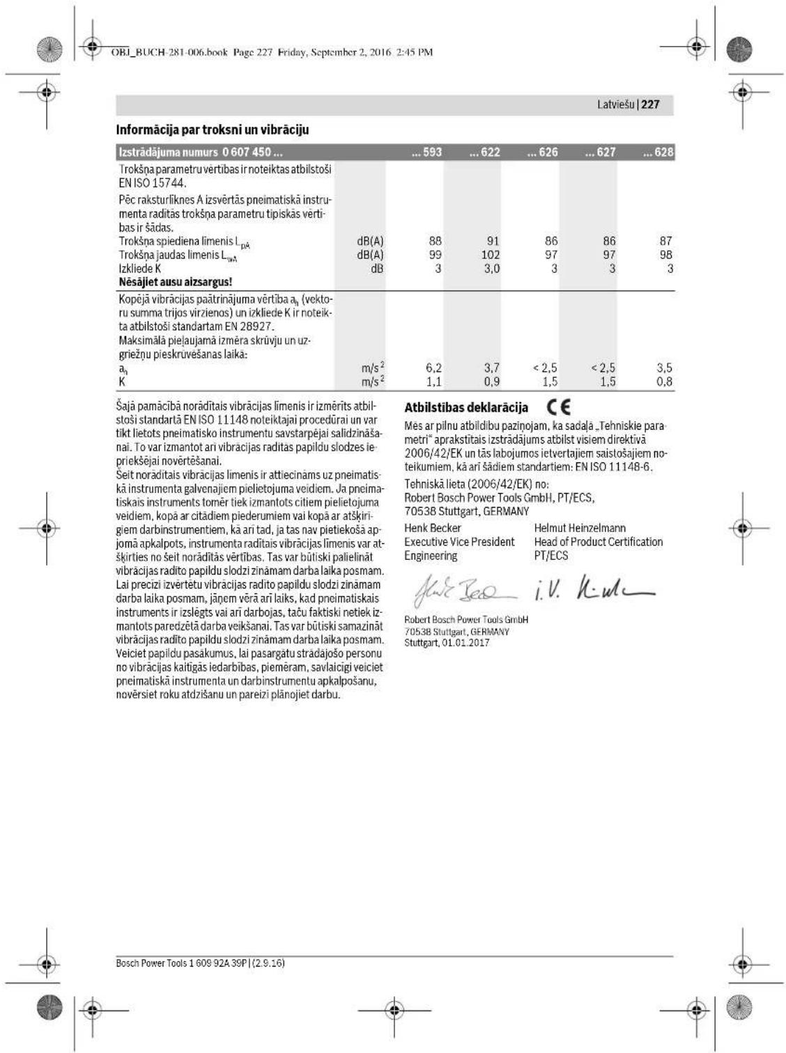

OBI_BUCH-281-006.book Page 230 Friday, September 2, 2016 2:45 PM
230|Latviesu
pievienojet pneimatisko instrumentu gaisa spiedientiklam (skatil sadalu, "Gaisa padeve" lappuse 228) un'aujiet tam darbotes 5-10 sekundes, apslaukot izdaljusos uar auduma gabalin. Ja pneimatiskais instruments igaku laiku nav darbinats, pirms ta lietoanas viemner veiciet iepriks apraksito proceduro.
Regulara apkalposana
Kvaliféctam specialistam laiku pa laikam jäparbauda pneimata zînejbe blivaplaksnes un vajadzibas gadijuma tãs jaapmaina viétam.
Pneimatiska instrumenta elošana
Pneimatska instrumenta tiešajai elošanai va ilas pievienošanai saspiestajam gaisam kondicionesanas ierice lietojama dzinju eja SAE 10 vai SAE 20.
Piezime. Pärak liels smervielas daudzums nelabvigi etekme triecienskruvgrieza jaudu, jo izraisa triecienmehanna salipsanu.
0607450593 (attels D)
Lai nodrosinatu pneimatiska dzinejao elosan, instrumentairieibuevaellaskamera 20.Ja netiek lietota gaise elosanas ierie, sikamera vismaz reizi dienaja piepildaarlespiiedenisrfici.
- Sim nolukam pagriezieit pneimatisiko instrumentu ta, lai takorturis buvi vosts ausep.
- Ari mererotu sesstura stienatslegu izskruvejit aidares skruj
-lepildiet ellas kamera 20 dzineju ellu.
- No jauna stingri pieskru vejiet aizdares skruvi 9.
060745062.(attelsE)
Vélakais pec 60 darba studam tricienskrüvgräża tricienmehnennia nedaudz jäeello.
- Sim nolukam pagrieziet pneimatisko instrumentu ta, lia ta rokturis bute verts ausgup.
- Ar piemerotu se sestura stienatslegu izskruvejiet aizdares skrivi 9
Caur aidzears skruves atverumu iepildet triecienmehannisma dzineju ellu. -
No jauna stingri pieskruveijiet aizdares skruvi 9. Aptuveni pec 100000 skruveesan operacijam no jauna javie trieci mechnanica elošana.
-
Süm nolükan pagriziet pneimatakiagnostik unentu à, la tə korturis bʊt vɛrs augsp.
- Ar piemerotu sesstura stienatslegu izskruvejiet aizdares skrivji 9
- Nolejiet izstradato elju tai, lia netaiktu nodarifts kaitejums apkartéi jidavi.
Caur aizdares skruves atverumu iepildet tricienmehanismazdineju elluelepidaam dzineju ellas daudzums ir noradits attieigaj tabulas aile (skati sadalu Tehniskie parmetri). - Apslaukiet parljuaso ellu ar mikstu lupatinu.
No jauna stingri pieskruejiet aizdares skruvi 9.
Tadu pneimatisko instrumentu elošana, kas nepieder pie sérijas CLEAN
Visiem Bosch pneimatiskajemi instrumentien, kas nepieder pie sierijas CLEAN (tie ir apgadati ar ipaša veida pneimatiskajemi dzinejem, kas darbojas bez ellas piajaukuma pivadajamaj gaisam), jäpvada saspisteis gaiss, kam siku pilieni-ru neva vestà passàviigti tiep jieukáta alla. Šoz devenmu večic ipaša saspistá gaisa elosanas ierice, kas darbojas pneimatiskajam instrumentam pievionotas saspisté gaisa kondiconešanas ierices sastava (sikaku informaciju par to var sanem't no firmas, kas razo kompressorus).
Piederumi
Lai iepazitos ar pilnu augstas kvalitates piederumu programmu, ataveriet interneta vietni www.bosch-pt.com vai griiezties kada no specializetajam tirdirzniebicas vietnam.
OBI_BUCH-281-006.book Page 231 Friday, September 2, 2016 2:45 PM

Lietuviskai 231
Lietuviskai
Saugos nuorodos
Bendrieji saugaus darbo su pneumatinais jrankiais nurodymai
ISPEJIMAS
OBI_BUCH-281-006.book Page 233 Friday, September 2, 2016 2:45 PM

Lietuviskai 233
OBI_BUCH-281-006.book Page 234 Friday, September 2, 2016 2:45 PM
234 | Lietuviškai
OBI_BUCH-281-006.book Page 235 Friday, September 2, 2016 2:45 PM

Lietuviskai 235
Executive Vice President Engineering
Helmut Heinzelmann
Head of Product Certification
PT/ECS


Robert Bosch Power Tools GmbH
70538 Stuttgart,GERMANY
Phone:+81 01 2012017
Sutgat,01.01.2017
Montavimas
OBI_BUCH-281-006.book Page 237 Friday, September 2, 2016 2:45 PM
Lietuviskai 237
Regularius valymas (zr. pav. C)
Regulariai valkyite pneumatinio jranko orjo kleidimo angooje esanti sieteli. Tuo tklsu nusukite zaros jmoja 15 arba zaros atvamzdj 18 ir nuo sietilo pašalinkite dulkes i nešavarumus. Tada veli tvirtai užverkite zaros atvamzdj.
Suslégame erte asesitant vanduo ir nesvarum dalelesukelia rudijima ir mentaliu, voztuvu bei kitu dilu susidevejima. Siekiant sengtir rudijima ir susidevejima, jaisinkte oiro tiekimo anga 7 Keleta lau variklio alyvos. Po to vel prijunkite pneumatin jranki prie susiego t oire kiko sistemas (2r. "Prijungimas prie susiego oiro tiekimo systemos", psl. 235) Ir junjkte jranki 5-10 sekundziu, tu paiciu metu valykite istekancia hyau audiini. Jeigu pneumatin |rankis bus nenaudojas ilgesnilaika, visada atlikite sia sutepimo procedura.
Elline techninen priezūrā
Specialistai turi periodiskai patikrinti ir, jeirekia, pakeisti varikinto meistei.
Pneumatinio irankio tepimas
Pneumatinio jrankio tiesioginiam tepimui ir maisymui joruslegto oro pravoosimo bloke naudokite varikliq alyva SAE 10 arba SAE20.
Nuoroda: Per didelis ahyos kieki dorjak smuginio suktu-vo naumui, nes u2skemsa smuginis mechanizmas.
0607450593 (zr.pav.D)
Pneumatiniam variiklii tepi yra jmontuota alyvos k
mera 20. Jei alyvos purskikis nenaudojasms, pneu
matiniu tepalo svirkstu kamera reika pripildyt bient
karta per diena.
- Pneumatinjrankj pasukite taip, kad rankena buty nukreipta aukstj.
-Tinkamu sesiabriauniu raktu issukite srieginj dangtelj 9.
-Alyvos kamera 20 pridiykde varlikli alyvos. Vel tvirtai uzukite siregnj dantgel 9.
060745062.(zr.pav.E)
Ne velau kaip po 60 darbo valandy reikia siek tiek pa- tepi smuginio sukturno smuginj mechanizma.
Pneumatinjrankj pasukite taip, kad rankena botu nukreip a tauk'st.
Tinkamu seisiabriauni raktu issukite sriegin dangtelj 9.
- Plkite varikilij alvyj smugin mechanizma per srieginiame dangelteyse sanca angia.
Vetvirtaiuzukite srieginj dangtelj 9.
- Pneumatinjrankj pasukite taip, kad rankena botu nukreip taaukstyn.
Tinkamu seisiabriauni raktu issukite sriegin dangtelj 9.
- Plkite varikilij alya j smugin mechanizma per srieginiame dangelteje esanda angia.
Vetvirtaiuzukite srieginj dangtelj 9.
MaDaqgo 100000 sukimo operaciju smugin mechanizmaj reikla is naujo patepi.
Pneumatinjrankj pasukite taip, kad rankena butu nukreip a taukint.
Tinkamu seiabriauniu raktu issukite srieginj dangtelj 9.
Panaudota alvya ispilkite laikydamiesi apinkos apsaugos rekalavalinak.
- Pilkite varikiu alvyj smugin mechanizma per srieginiame dangtelye esanci anga. Varikiu alvos kiekis, kurj reikia jpili, pateiitas varikiu alvayi skirtoje lenteles eiluteje (Zr. "Techniain duomens").
Pneumatinjrankj pasukite taip, kad rankena butu nukreip a taukint.
Tinkamu seiabriauniu raktu issukite srieginj dangtelj 9.
- Pilkite varikiu alvyj smugin mechanizma per srieginiame dangtelye esanci anga. Varikiu alvos kiekis, kurj reikia jpili, pateiitas varikiu alvayi skirtoje lenteles eiluteje (Zr. "Techniain duomens").
Issiliejusia ayva nuvalkyite minksta sluoste.
- Vel tvirtai uzsukite srieginj dangtelj 9.
Pneumatiniu jrankiu, kurie nepriklauso CLEAN serjai, tepimas
Visiens Bosch pneumatiniams jrankiams, kurie nepriskiriami prie CLEAN serijos (specialus tipso pneumatiniarmarikial, kuriemiels kiesiamas suslegtasoras be alvys), pratekanciususlegto oro drauta reikia visada sumaitytu su alvys ruku. Butinasuslegto oro tepimo itaisa yra priei pneumatinjrkjprijungtame suslegto oro paruoso bloke (issamesnius duomenis jums gali patekti kompressorig gamintojas).
Papildomajranga
Visa kokyibskos papildomos jrangos programa galite rasti internete www.bosch-pt.com arba pasiteirauti specializuotos prekybos astlovo.
OBI_BUCH-281-006.book Page 240 Friday, September 2, 2016 2:45 PM
240|中文
代表符号
OBI_BUCH-281-006.book Page 241 Friday, September 2, 2016 3:01 PM
中文|241
技术数据
Executive Vice President
Engineering
Helmut Heinzelmann
Head of Product Certification
PT/ECS

V.H. MC = 90^
Robert Bosch Power Tools GmbH
70538 Stuttgart,GERMANY
Stuttgart, 01.01.2017
Bosch Power Tools 1609 924 39P(2.9.16)


OBI_BUCH-281-006.book Page 243 Friday, September 2, 2016 2:45 PM
中文|243
0607450 622

"Forward" 代表正转。

"Reverse" 代表逆转。
OBI_BUCH-281-006.book Page 245 Friday, September 2, 2016 2:45 PM
中文|245
中文
安全規章
針對氣動工具的一般性安全指示
OBI_BUCH-281-006.book Page 246 Friday, September 2, 2016 2:45 PM
246|中文
氣動衝擊起子機的安全注意事項
OBI_BUCH-281-006.book Page 247 Friday, September 2, 2016 2:45 PM
中文|247
代表符號
OBI_BUCH-281-006.book Page 248 Friday, September 2, 2016 2:45 PM
248|中文
技術性數據
OBI_BUCH-281-006.book Page 249 Friday, September 2, 2016 2:45 PM
中文|249
合格聲明 C
Executive Vice President Head of Product Certification
Engineering
[h : w]
Robert Bosch Power Tools GmbH
70538 Stuttgart,GERMANY
Stuttgart, 01.01.2017
1)吉其人云义用元国,月士贝士贝士贝士贝士贝士贝士贝士贝士贝士贝士贝士贝士贝士贝士贝士贝士贝士贝士贝士贝士贝士贝士贝士贝士贝士贝士贝士贝士贝士贝士贝士贝士贝士贝士贝士贝士贝士贝士贝士贝士贝士贝士贝士贝士贝士贝士贝士贝士贝士贝士
青 皂藻,
一 云云云云云云云云云云云云云云云云云云云云云云云云云云云云云云云云云云云云云云云云云云云云云云云云云云云云云云云云云云云云云云云云云云云云云云云云云云云云云云云云云云云云云云云云云云云云云云云云云云云云
伊通公的
OBI_BUCH-281-006.book Page 253 Friday, September 2, 2016 2:45 PM

中国银行|253
漢上達日則曾不之,其在朝而有,亦不。
Aoei公,默战,自人公,动中,实电,
国的,
- 哉云糟藻則是藥國,躁藻對藥藥藥藥藥藥藥藥藥藥藥藥藥藥藥藥藥藥藥藥藥藥藥藥藥藥藥藥藥藥藥藥藥藥藥藥藥藥藥藥藥藥藥藥藥藥藥藥藥藥藥藥藥藥藥藥藥藥藥藥藥藥藥藥藥藥藥藥藥藥藥藥藥藥藥藥藥藥藥藥藥藥藥藥藥藥藥藥藥
山
国的云
()
OBI_BUCH-281-006.book Page 254 Friday, September 2, 2016 2:45 PM
254|中国
OBI_BUCH-281-006.book Page 255 Friday, September 2, 2016 2:45 PM


| 9 bedroom suite | 16 floorings |
| 10 bedroom suite | 17 living room |
| 11 bedrooms per family | 18 floorings |
| 12 rooms | 19 bedrooms |
| 13 rooms | 20 rooms |
| 14 floors of the tower | 多媒体会议室,卧室,客厅,餐厅,卧室,餐厅,卧室,餐厅,卧室,餐厅,卧室,餐厅,卧室,餐厅,卧室,餐厅,卧室,餐厅,卧室,餐厅,卧室,餐厅,卧室,餐厅,卧室,餐厅,卧室,餐厅,卧室,餐厅,卧室,餐厅,卧室,餐厅,卧室,餐厅,卧室,餐厅,卧室,餐厅,卧室,餐厅,卧室,餐厅,卧室,餐厅,卧室,餐厅,卧室,餐厅,卧室,餐厅,卧室,餐厅,餐厅,卧室,餐厅,卧室,餐厅,卧室,餐厅,卧室,餐厅,卧室,餐厅,卧室,餐厅,卧室,餐厅,卧室,餐厅,卧室,餐厅,卧室,餐厅,卧室,餐厅,卧室,餐厅,卧室,餐厅,卧室,餐厅,卧室,餐厅,卧室,餐厅,卧室,餐厅,卧室,餐厅,卧室,餐厅,卧室,餐厅,卧室,餐厅,卧室,餐厅,卧室,餐厅,卧室,餐厅, |
新
Executive Vice President Head of Product Certification
Engineering

iV. k = m _____
Robert Bosch Power Tools GmbH 70538 Stuttgart, GERMANY
info@bosch.com
丕
中
- 云 云
封山
:龍龍龍龍龍龍龍龍龍龍龍龍龍龍龍龍龍龍龍龍龍龍龍龍龍龍龍龍龍龍龍龍龍龍龍龍龍龍龍龍龍龍龍龍龍龍龍龍龍龍龍龍龍龍龍龍龍
0607450593(二B)
- 10
一函士名15电国用的
OBI_BUCH-281-006.book Page 258 Friday, September 2, 2016 2:45 PM
258|
日是云,
奉功
多托贝在的,
[
海云国中日
:G:H2L 1
0607450593(D
哉藻藻藻藻藻藻藻藻藻藻藻藻藻藻藻藻藻藻藻藻藻藻藻藻藻藻藻藻藻藻藻藻藻藻藻藻藻藻藻藻藻藻藻藻藻藻藻藻藻藻藻藻藻藻藻藻藻藻藻藻


OBI_BUCH-281-006.book Page 259 Friday, September 2, 2016 2:45 PM
259
nwn
ng=
nngl山Wnnaaannnnn
A 1
wannnnnnaaennnnnnnnnn
1
a 1000000000000000000000000000000000000000000000000000000
1 2
aannnnnne
aannnnnnaanennnnnnnnnnnnnnnnnnnnnnnnnnnnnnnnnnnnnnnnnnnnnnnnnnnnnnnnnnnnnnnnnnnnnnnnnnnnnnnnnnnnnnnnnnnnnnnnnnnnnnnnnnnn
aannnnnnaanennnnnnaanennnnnnnnnnnnnnnnnnnnnnnnnnnnnnnnnnnnnnnnnnnnnnnnnnnnnnnnnnnnnnnnnnnnnnnnnnnnnnnnnnnnnnnnnnnnnnnnnnnnnnnnnnnnnnnnnnnnnnnnnnnnnnnnnnnnnnnnnnnnnnnn
Buaaannnnae annnnnne aannnne nnnnne anennnne
gululnnaaannnnnnae annnnnnae aannnnnnae
TJUANANJUAN
Tnueovaguanwunwun wunrtyuau nnuuug uanuunuunuunuunuunuunuunuunuunuunuunuunuunuunuunuunuunuunuunuunuunuunuunuunu
OBI_BUCH-281-006.book Page 260 Friday, September 2, 2016 2:45 PM
2601m7n
y
1nannnnn nnnnnnnnnnnnnnnnnnnnnnnnnnnnnnnnnnnnnnnnnnnnnnnnnnnnnnnnnnnnnnnnnnnnnnnnnnnnnnnnnnnnnnnnnnnnnnnnnnnnnnnnnnnnnnnnnnnnnnnnnnnnnnnn nnannn
AeauuueuuuueuuuuuuuuuuuuuuuuuuuuuuuuuuuuuuuuuuuuuuuuuuuuuuuuuuuuuuuuuuuuuuuuuuuuuuuuuuuuuuuuuuuuuuuuuuuuuuuuuuuuuuuuuuuuuuuuuuuuuuuuuuuuuuuuuuuuuuuuuuuuuuuuuuuuuuuuuuuuuuuuuuuuuuuuuuuuuuUU
mnnnnaaannnnnnnnnnnnnnnnnnnnnnnnnnnnnnnnnnnnnnnnnnnnnnnnnnnnnnnnnnnnnnnnnnnnnnnnnnnnnnnnnnnnnnnnnnnnnnnnnnnnnnnnnnnnnnnnnnnn
179
OBI_BUCH-281-006.book Page 261 Friday, September 2, 2016 2:45 PM

mnnn261
aannnnnnaanennnnnnnnnnnnnnnnnnnnnnnnnnnnnnnnnnnnnnnnnnnnnnnnnnnnnnnnnnnnnnnnnnnnnnnnnnnnnnnnnnnnnnnnnnnnnnnnnnnnnnnnnnnnnnnnnnnnnnnnnnnnnnnnnnnnnnnnnnnnnnnnnnnnnnnnnnnnn nn
aannnnnnaeennnnne nnnnnnnnnnnnnnnnnnnnnnnnnnnnnnnnnnnnnnnnnnnnnnnnnnnnnnnnnnnnnnnnnnnnnnnnnnnnnnnnnnnnnnnnnnnnnnnnnnnnnnnnnnnnnnnnnnnnnnn
wunwunwnnwnnnnnnnnnnnnnnnnnnnnnnnnnnnnnnnnnnnnnnnnnnnnnnnnnnnnnnnnnnnnnnnnnnnnnnnnnnnnnnnnnnnnnnnnnnnnnnnnnnnnnnnnnnnnnnnnnnnnnnnnnnnnnnnnnnnnn
aannnnae nnnnne aen annnne
nannnnnnnnnnnnnnnnnnnnnnnnnnnnnnnnnnnnnnnnnnnnnnnnnnnnnnnnnnnnnnnnnnnnnnnnnnnnnnnnnnnnnnnnnnnnnnnnnnnnnnnnnnnnnnnnnnnnnnnn
B
nulululntuunauvuaanrnnn n
aunuunununu unnuuun uauuuu uuaaunuunuunu uuuuuuuuuuuuuuuuuuuuuuuuuuuuuuuuuuuuuuuuuuuuuuuuuuuuuuuuuuuuuuuuuuuuuuuuuuuuuuuuuuuuuuuuuuuuuuuuuuuuuuuuuuuuuuuuuuuuuuuuuuuuuuuuuuuuuuuuuuuuuuuuuuuuuuuuuuuuuuuuuuuuuuuuuuuuuuuuuuuuuuuuuuuuuuuuuuuUU
wnnnaaennnnnaa (bayonet coupling) nannnnnnae nnne nnnnnnnae (whipcheck) nnnnnnnnnnnnnae nnnnnnnnnae nnnnnnnnnae
a#
auiuuiuuiuuiuuiuuiuuiuuiuuiuuiuuiuuiuuiuuiuuiuuiuuiuuiuuiuuiuuiuuiuuiuuiuuiuuiuuiuuiuuiuuiuuiuuiuuiuuiuuiuuiuuiuuiuuiuuiuuiuuiuuiuuiuuiuuiuuiuuiuuiuuiuui
mnnnnaeannnnnneennnnnnnnnnnnnnnnnnnnnnnnnnnnnnnnnnnnnnnnnnnnnnnnnnnnnnnnnnnnnnnnnnnnnnnnnnnnnnnnnnnnnnnnnnnnnnnnnnnnnnnnnnnnnnnnnnnnnnnnnnnnnnnnnnnnn nn nannnannnannnannnannnannnannnannnannnannnannnannnannnannnannnannnannnannnannnannnannnannnannnannnannnannnannnannnannnannnannnannnannnannnannnannnannnannnannnannnannnannnannnannnannnannnannnannnannnannnann
aynn
aayyanaeululunuunuunuunuunuun uuuu uuuu uuuu uuuu uuuu uuuu uuuu uuuu uuuu uuuu uuuu uuuu uuuu uuuu uuuu uuuu uuuu uuuu uuuu uuuu uuuu uuuu uuuu uuuu uuuu uuuu uuuu uuuu uuuu uuuu uuuu uuuu uuuu uuuu
海

nauuue uuuuuaa aannnnnnae nnnnne nnnnne nnnnne nnnnne nnnnne nnnnne nnnnne nnnnne nnnnne nnnnne nnnnne nnnnne nnnnne nnnnne nnnnne nnnnne nnnnne nnnnne nnnnne nnnnne nnnnne nnnnne nnnnne nnnnne nnnnne nnnnnee nnnnne nnnnne nnnnne nnnnne nnnnne nnnnne nnnnne nnnnne nnnnne nnnnne nnnnne nnnnne nnnnne nnnnne nnnnne nnnnne nnnnne nnnnne nnnnne nnnnne nnnnne nnnnne nnnnne nennne nnnnne nnnnne nnnnne nnnnne nnnnne nnnnne nnnnne nnnnne nnnnne nnnnne nannnee

mnnnnaaannnnn

OBI_BUCH-281-006.book Page 262 Friday, September 2, 2016 2:45 PM
262 mnnn
77
#

OBI_BUCH-281-006.book Page 263 Friday, September 2, 2016 2:45 PM
myny 263
yaiuunuiuuauaa
| ENGLISH | ENGLISH | ENGLISH | ENGLISH | ENGLISH | ENGLISH |
| ENGLISH | ENGLISH | ENGLISH | ENGLISH | ENGLISH | ENGLISH |
| ENGLISH | ENGLISH | ENGLISH | ENGLISH | ENGLISH | ENGLISH |
| ENGLISH | ENGLISH | ENGLISH | ENGLISH | ENGLISH | ENGLISH |
| ENGLISH | ENGLISH | ENGLISH | ENGLISH | ENGLISH | ENGLISH |
| ENGLISH | ENGLISH | ENGLISH | ENGLISH | ENGLISH | ENGLISH |
Tnannnnnnaaennnnn nnnnnnnnnnnnnnnnnnnnnnnnnnnnnnnnnnnnnnnnnnnnnnnnnnnnnnnnnnnnnnnnnnnnnnnnnnnnnnnnnnnnnnnnnnnnnnnnnnnnnnnnnnnnnnnnnnnnnnnnnnnn nn
Tnannnnnnnnnnnnnnnnnnnnnnnnnnnnnnnnnnnnnnnnnnnnnnnnnnnnnnnnnnnnnnnnnnnnnnnnnnnnnnnnnnnnnnnnnnnnnnnnnnnnnnnnnnnnnnnnnnnnnnnnnnnnnnnnnnnnnnnnnnnnnnnnnn
nannnnnnnnnnnnnnnnnnnnnnnnnnnnnnnnnnnnnnnnnnnnnnnnnnnnnnnnnnnnnnnnnnnnnnnnnnnnnnnnnnnnnnnnnnnnnnnnnnnnnnnnnnnnnnnnnnnnnn
aannnnnnaanennnnnnnnnnnnnnnnnnnnnnnnnnnnnnnnnnnnnnnnnnnnnnnnnnnnnnnnnnnnnnnnnnnnnnnnnnnnnnnnnnnnnnnnnnnnnnnnnnnnnnnnnnnnnnnnnnnnnnnnnnnnnn
nannnnnnnnnnnnnnnnnnnnnnnnnnnnnnnnnnnnnnnnnnnnnnnnnnnnnnnnnnnnnnnnnnnnnnnnnnnnnnnnnnnnnnnnnnnnnnnnnnnnnnnnnnnnnnnnnnnnnnnnnnnnnnnnnnnnnnnnnnnnnnnnnnnnnnnnn nn nannn nannn nannn nannn nannn nannn nannn nannn nannn nannn nannn nannn nannn nannn nannn nannn nannn nannn nannn nannn nannn nannn nannn nannn nannn nannn nannn nannn nannn nannn nannn nannn nannn nannn nn annn nn annn nn annn nn annn nn annn nn annn nn annn nn annn nn annn nn annn nn annn nn annn nn annn nn annn nn annn nn annn nn annn nn annn nn annn nn annn nn annn nn annn nn annn nn annn nn annn nn annn nn annn nn annn nn annn nn annn nn annn nn ann
1

1
yannnnn nn nnnnnnnnnnnnnnnnnnnnnnnnnnnnnnnnnnnnnnnnnnnnnnnnnnnnnnnnnnnnnnnnnnnnnnnnnnnnnnnnnnnnnnnnnnnnnnnnnnnnnnnnnnnnnnnnnnnnnnnnnnnnnnnnnnnnnnnnnnnnnnnnn
Robert Bosch Power Tools GmbH, PT/ECS, 70538 Stuttgart, GERMANY
Henk Becker
Executive Vice President Engineering
Helmut Heinzelmann
Head of Product Certification PT/ECS

Robert Bosch Power Tools GmbH
70538 Stuttgart,GERMANY
Stlgtgat,01.01.2017
nnu
aunnnnnaeaaeaan
mnnnnaeauuueaennnneauuuuauauauauauauauauauauauauauauauauauauauauauauauauauauauauauauauauauauauauauauau
unu
40607450593m14 0607450622
aannnnnnae
nwnnnn (0607450622) (nannnna A)
- 1211111111111111111111111111111111111
- nonunu 13 aonuaa
- 141111111111111111111111111


OBI_BUCH-281-006.book Page 264 Friday, September 2, 2016 2:45 PM
264m
nT
→ 193700000000000000000000000000000000000000000000000000000000000000000000
Tulalamnnaaannnnnnaanennnnaanrnuu Tlu 1000000000000000000000000000000000000000000000000000000000
annnnnneaaaalnuuauuuuauuuaa uauuauu uauuuuuuuuuuuuuuuuuuuuuuuuuuuuuuuuuuuuuuuuuuuuuuuuuuuuuuuuuuuuuuuuuuuuuuuuuuuuuuuuuuuuuuuuuuuuuuuuuuuuuuuuuuuuuuuuuuuuuuuuuuuuuuuuuuuuuuuuuuuuuuuuuuuuuuuuuuuuuuuuuuuuuuuuuuuuuuuuuuuuuuuuuuuuuuuuuuuUU
mnnnnaeennnnneannnnnne nnnnne
aannnnnnae annnnnne aannnnnne nnnnnnne nnnnnnne nnnnnnne nnnnnnne nnnnnnne nnnnnnne nnnnnnne nnnnnnne nnnnnnne nnnnnnne nnnnnnne nnnnnnne nnnnnnne nnnnnnne nnnnnnne nnnnnnne nnnnnnne nnnnnnne nnnnnnne nnnnnnne nannnnnne nannnnnne nannnnnne nannnnnne nannnnnne nannnnnne nannnnnne nannnnnne nannnnnne nannnnnne nannnnnne nannnnnne nannnnnne nannnnnne nannnnnne nannnnnne nannnnnne nannnnnne nannnnnne nannnnnne nennnnnne nannnnnne nannnnnne nannnnnne nannnnnne nannnnnne nannnnnne nannnnnne nannnnnne nannnnnne nannnnnne nannnnnne nannnnnne nannnnnne nannnnnne nannnnnne nannnnnne nannnnnne nannnnnne nannnnnne namm
nannnnnnnnnnnnnnnnnnnnnnnnnnnnnnnnnnnnnnnnnnnnnnnnnnnnnnnnnnnnnnnnnnnnnn
wwW: nnnnnaaannnnnne aannnnnne
0607450593 (aannnnn B)
- 10007
15 15 7
16 17 15
0607450622/..626/..627/..628(annnnnnaC)
10 10 7
- 17 19 18
n
aannnnnnaeennnnnne aannnnnne nnnnnnne
aannnnnnae aannnnnne nnnnnnne annnnnne nnnnnnne nnnnnnne nnnnnnne nnnnnnne nnnnnnne nnnnnnne nnnnnnne nnnnnnne nnnnnnne nnnnnnne nnnnnnne nnnnnnne nnnnnnne nnnnnnne nnnnnnne nnnnnnne nnnnnnne nnnnnnne nnnnnnne nnnnnnne nannnnnne nannnnnne nannnnnne nannnnnne nannnnnne nannnnnne nannnnnne nannnnnne nannnnnne nannnnnne nannnnnne nannnnnne nannnnnne nannnnnne nannnnnne nannnnnne nannnnnne nannnnnne nannnnnne nannnnnne nennnnnne nannnnnne nannnnnne nannnnnne nannnnnne nannnnnne nannnnnne nannnnnne nannnnnne nannnnnne nannnnnne nannnnnne nannnnnne nannnnnne nannnnnne nannnnnne nannnnnne nannnnnne nannnnnne nannnnnne namm
#
- 1 1 1 1 1 1 1 1 1 1 1 1 1 1 1 1 1 1 1 1 1 1 1 1 1 1 1 1 1 1 1 1
Iowonnnoofoolnnaeunnneauuulnueu (e"ayamnuwtn)
aia
#
- 1000000000000000000000000000000000000000000000000000
nuiu
山
uuaaunrnnnnaeannnnnnaeauanrnnn 6.3 u(9 uannnnnnn) Iaeiueeennnnnneaaen annnnnnnnnnnnnnnnnn
1 1
n
aannnnnannnnn 5 nnnnnnnnnnnnna
aunnnnnaeannnnnne aenrnnnne
0607450593
- 1
-
0607450622
F "un" (Forward) mnnn nn
-
5uunuunuuuunuuuuuuuuuuuuuuuuuuuuuuuuuuuuuuuuuuuuuuuuuuuuuuuuuuuuuuuuuuuuuuuuuuuuuuuuuuuuuuuuuuuuuuuuuuuuuuuuuuuuuuuuuuuuuuuuuuuuuuuuuuuuuuuuuuuuuuuuuuuuuuuuuuuuuuuuuuuuuuuuuuuuuuuuuuuuuuuuuuuuuuuuuuuuuuuuuuuuUU
-
1


OBI_BUCH-281-006.book Page 265 Friday, September 2, 2016 2:45 PM
265
0607450626/..627/..628
B "nann" (Reverse) nannnnn
F "unun" (Forward) nun nn mnnn
- 1
aannnnnnae annnnne aen ananennnne nnnnnnne 1 1
nna-n-
mnnnne nnnnnnnnnnnnnnnnnnnnnnnnnnnnnnnnnnnnnnnnnnnnnnnnnnnnnnnnnnnnnnnnnnnnnnnnnnnnnnnnnnnnnnnnnnnnnnnnnnnnnnnnnnnnnnnnnnnnnnnnnnnnnnnnnnnnnnnnnn nn
- 100000000000000000000000000000000000000000000
- 8
wnnnn: mnnnnnnnnnnnnnnnnnnnnnnnnnnnnnnnnnnnnnnnnnnnnnnnnnnnnnnnnnnnnnnnnnnnnnnnnnnnnnnnnnnnnnnnnnnnnnnnnnnnnnnnnnnnnnnnnnnnnnnnnnnnnnnnnnnnnnnnnnnnnnnnnnnnnnnn nn nannn nannn nannn nannn nannn nannn nannn nannn nannn nannn nannn nannn nannn nannn nannn nannn nannn nannn nannn nannn nannn nannn nannn nannn nannn nannn nannn nannn nannn nannn nannn nannn nannn nannn nn annn nn annn nn annn nn annn nn annn nn annn nn annn nn annn nn annn nn annn nn annn nn annn nn annn nn annn nn annn nn annn nn annn nn annn nn annn nn annn nn annn nn annn nn annn nn annn nn annn nn annn nn annn nn annn nn annn nn annn nn annn nn annn nn annn nn ann
Jauununnnn
OBI_BUCH-281-006.book Page 270 Friday, September 2, 2016 2:45 PM
OBI_BUCH-281-006.book Page 274 Friday, September 2, 2016 2:45 PM
Nguyen Tác An Toàn Chung Danh Cho Dung Cu Nen Khi
CANH BAO Truc khi lap dat, van hanh, sua chu, bao tri va thay phi kien cung nhu truc khi lam vlc gan dung cu nen khi, xin vui long doc va tuan theo tat ca moi huong dan. Khong thuc hiem theo cacloi canh bao an toan say da co the bi tan thuong nghiem tong. Giu lai ta cac huong dan de tham khao ve sau, va tao dileu kien cho nguoi van hanh san dc su dung.
Khu vuc lam viec an toan
Luu y den cac be mat co the tro nen trotr, phat sinh tu viec su dung may, va cac nguy him do yap phi duq cu nki hay voi ong thu luc. Trot chan, vap va tegna lac fy do chinh gay ton thuong ndi lam viec.
Khong van hanh dung cu nén khi o moi truong chay n6,chang han nuo co chat long de chay, khi gas hay rac. Trong khi lam viec voi vat gia cong,cac tia la bana ra co the lam rac bat la hay ngun khoi.
Giu che tre em va nguoi dung gan cach xa khoi nol lam viec cua ban trong khi van hanh dung cu nen khi. Su maf tap trung vi nhung nguoi khac co the gay cho ban maf su kiem soat dung cu nen khi.
Su'an toan voi dung cu nen khi
Khong bao gio duoc huong thang luong hoi vao chinh nguoi ban hay nguoi khac gan ben, vua dau hoi lanh thanh khoi tan. Hoi nen co thegay ra cac ton thuong ngiem trong.
Kiem tra cac cac phan dai vo duong cung cap hoi. Tá cac cac bó bao tri, bó não, voi cóng hu pi diap ung cac dac tian khy tuat duri hinn thuc ap suai va khoi luyng khi. Ap suai qua thaip lam suy giam su hoat dong cua dung cu nen khi; ap suai qua cao co the lam hu hai vat lieu va gay ton thuong cho chinh minh.
Bao voi ong khong bi that nut, nghen, dung moi lam tan, cac canh ben. Gifu ong cach xa nhiet, dau, vac bo phan xoy. Thay ngay voi ong bi hu hong. Mott duong cung cap ho bi hong co the gay voi ong khi nen vung vay va co the gay t on thuong cho chinh minh. Bui bi day tung hay cac manh vun co the gay t on thuong ma!.
Bao dam tep dan hoi vong luon luon duoc siet that chat. Kep dan hoi vong bj hu hai co the lam mat kiem soat hoi thoat ra naoai.
An toan canh
Gi tinh tao, biét ro ban dang lam gi, v suy xet hop ly khi su dung dung cu nen khi. Khong duoc sur dung cu nen khi kang met moi hay dang bi anh huong cua chat gay nghiens, ruu, hay duoc pham. Mto thoang ma tap trung tong khi vananh dung cu nen khi co theg y ton thuong cho chinh minh.
Su dung trang thiet bi bao hca nhan. Luon luon mang kinh bao ve mat. Mang trang thiet bi bao hca nhan - nu'la mata nhong ho doc, giay an loan chong truot, mu bao hoy baov theh inh giac - theo sur chi dao cua chu su dung lao dong cua ban hay tuan theo ca dieu khoan yeau cau dai voci cong vioc sur bao vse suc khoe, lam giam nguy co gay ton thuong cho chin minh.
Ngān ngua may khoi dong bat ng. Bao dam dung cu nen khi da duc tāt truc o khi noi vao nguon cung cap hoi, nhac may len hay di chuyen may. Khi ngon tan cu bān ngang trén cong tāc Tat/Mo khi di chuyen dung cu nen khi hay khi noi dung cu nen khi vao nguon cung cap hoi khi may dung duc mc, tai nan co the xay ra.
Thao bat cu dung cu dieu chinh nao ra trucckhi cho dung cu nen khi hoat dong. Chia vandaioc hay chia van con gan dinh trong bo phanquay cu dung cu nen khi co they tan thuongcho chinhhinm.
Khong duoc voi. Giu tu the dung thich hop va can bang trong moi luc. Dieu nay lam viec dieu khien dung cu men khf duoc tot hon trong cac tinh huo ng bng.
An mac phu hop. Khong mac quan ao rong thung thinh hay mang trang suc. Giu toc, quan ao va gang tay cua ban cach xa cac bo chan chuyen dong. Quan ao rong thung thinh, do tranq suc hay toc dai co the bi quan vao cac bo chan chuyen dong.
Khong duchitruc tiep khi thai. Tranh khong de malphran voi khi thai.Khi thai cua dung cu nen khi co the chu nauc, dau, manh vun kim loai vcan ba tbo phan nen hdiu nay co the gay nguy hai cho suc khec con ngubi.
Surdung va cham soc dung cu nen khi
Su dung cac thiiet bi kep hay mo cap de giu an toan va jiu do cho vatgia cong. Giu vat gia cong bang tay hay tv vao ngui se khong lam cho su hoat dong cua dung cu nen khi duoc an toan.
Khong lam dung cu nen khi bi qua tai. Su dung dung cu nen khi theo cong viec du dinh cua ban. Dung cu nen khi dung loai se thuc hieng cong
Tieng Viet|277
viectotvaantoanhondo ma mayduoc thiet ke.
Khong su dung dung cu nén khi cong tac Tatmo bu hong. Mot dung cu nén khi khong the dieu khien dac bang cong tac la nguy hiem va phai duc sua chuia.
Thao nguon cung cap hoi truck hiuchien bát cu dieu chinh, thay phu kien, hoac khong sū dung den trong moi thoi gian dai. Bié naph an toan nay ngn ngua su v o tinh lam dung cu nen khi khoi dong.
Cat giung dung cu nen khi khong sury dung den o noi gnoi taml voi cua tr em. Khong cho phep nhng nguoi khong am hiieu dung cu nen khi hay khong biht nhuong huoang dan nay su dung thiet bj.Dung cu nen khi nguyi hiem khi nam tren tay nguoi su dung khong co kinh nghim.
Bao tri dung cu nen khi can than. Kiem tra su sal lech hay cac bo phan chuyen dong bi tac, bo phan bi vovatac cac tinh trangh kac co the anh huong den sur hoat dong cu dung cu nen khi.Dua cac bo phan bu hong di sua chu trucoc khi su dung dung cu nen khi. Nheiu tai nan xayrdo su bao tri dung cu nen khi kem.
Su dung dung cu nen khi, phu kien, dung cu ung dung v. v. du' theo cac hong dan nay. Hay luu y den dieu kien lam vic va cac cong viec se thuc hien. Dieu nay lam giam su phat sinh bui. su rung va tieng on den muc do lon nhat.
Dungcun nén khi nen duroc lap dat, dieu chinh hay su dung danri nguo van hanh co nang luc va co tay nghe.
Khongcai biendungcu nén khi bangbat cir hinh tncn.Sucai biéco the lam giem hiue qua cua cac bian phap an toan,va lam tang nguy co cho ngoi van hanh.
Bao Tri
Dua dung cu nén khi cua ban den tho chuyen mon chi su dung phu tung cung loi chinh hang de bao tri va sua chu. Dieu nay se dam bao su an toan cu dung cu nen khi duqc gu nguyen.
Huong dan an toan dang cho sung khi nén xiet luc
Klém tra néu nhu bang ghi chung loi may có con ce do dacu. néu can, dé nghi nha sān xuat cung cap dé theye.
Trong truong hop vatgia cong hay phu kien, hay ngay chinh dung cu nen khi bo, cac bo phan co the ban tung ra chung quanh o toc do cao.
Trong thoi gian van hanh, sua chu ya hay bao tri va khi they cac phu kién tren dung cu nen khi,
luon luon mang kinh chong va dap bao ve mat. Muc do can bao vé can phai duoc luong dinh ri néng cho tung umd dung.
Khong duoc cho dung cu nén khi hoat dong khi dang mang ben nguoi. Dung cu dau gai dang quay co the cuon vao quan ao va co the gay thuong tich.
Mang gang tay kin sat. Luong khi nén lam cho tay nam cua dung cu nen khi lan. Ban tan ducg giam thi nhy cam voi surng. Gang tay rong co the bi cac bo phan chuyen dong cuon vao.
Khong dé tay ban gan chia vān ong va dung cu ung dung xoay. Khong bao gio duoc nam dung cu ung dung hany bo phan truyen dong. Ban co the tu lam t on thuong chin minh.
Cantrongkhlkhonggian lamviebcjhanche. Tranh tayra xahoi thanh chuyen hoan ngau luc.Luc phan hoci kha nang gay thuong tich do bi kep hay chen chat.
Nguoi van hanh va nhan vien bao tri phai DAY du the luc de xur ly kich thuoc, trong luong va luc ca dung cu nen khi.
Hay san sang umgh po voic dac dong thai bat ngocua dung cu nen kco the phat sinh do luc phan ung hay su vocua dung cu umng. Gurl chat tay nam trn dung cu nen kvi datturthe than theban va hai canh tay cho phep ban cuong lai nhung dong thai nuv. Nhong sur phong ngua nay co the tranh bi ton thuong.
Sdung cac phu tro de hap thu luc van phan ung, nhu cac thi et bi htro. Neu dieu nay la khong the duoc, su dung tam nau phu.
Trong truong hop nguon hoi cung cap bi gian doan hay ap suat hoang giang, ta dung cu nen khi. Kiem tra ap suat hoat dong va khdi dong may tro lai khi ap suat hoat dong o muc tot nhai.
Khi sur dung dung cu nen khi de thuc hién cac hoat dong co lien quan den cong viec, ngroi van hanh co the cam nhn cac cam giac kho chu o tay, canh tay, hai vai, vung co va cac bo phan co the khac.
Khl lam voc voi dung cu nen khi, tao tu the dung thoa mai, gi chac dung cu va tranh cac vi the khong thuan loi hay nhung tu the nhu vay o hung noi ma ban kho gur dcu shang bang. Doi voi nhung cong viec keo dai, ngoi van hanh phai they doi the dung hay tu the, cach nay giup tranh duc su kho chu va met moi.
Gia sun ngloi van hanh may nhan thay cac triu chu ng nuon non dal dang, kho chu, tim dap manh, dau, ngua ngay, te dai, bong rat hay te cung. Khong duoc bo qua nhung canh


OBI_BUCH-281-006.book Page 279 Friday, September 2, 2016 2:45 PM
Tieng Viet|279
BieuTuong YNghia

Mang dung cu bao vé tai

Mang kinh an toan/kinh bao holaodong
W Watt (don vi dien nang) Cong suat
Newton metre (don vi Don vi do nang
Bieu tving danch cho 6
cām sāu canh
Biéu tuo ng chi dαu
truyen dong yuong
Ren buac nhc US
UNF (Dong Ren Buoc Nho
ThongNhatQuocGiai
G Ren Whitworth (he
Anh)
NPT Renong liu chuang
quocgia
R
Chieu quay phai
Chieu quay
E

Chieuquaytrai
Senior Vice President Head of Product Certification
Engineering
PT/ECS

Robert Bosch Power Tools GmbH,
70538 Stuttgart,GERMANY
Stuttgart, 01.01.2017

j0sJ 1sswU Jg
jg jbgaiollgaiocJusawu cuj
jooaiuui uuiuuiu
Jkuqui qiu y li.1ggl soly Lglo
Jgaoo Jc
| الجُد الجُد | الجُد | الجُد | |||
| الجُد الجُد | الجُد | الجُد | |||
| الجُد الجُد | الجُد | الجُد | |||
| الجُد الجُد | الجُد | الجُد | |||
| الجُد الجُد | الجُد | الجُد | |||
| الجُد الجُد | \(الجُد\)\(الجُد | \(الجُد\)\(الجُd\)\(الجُd\)\(الجُd\)\(الجُd\)\(الجُd\)\(الجُd\)\(الجُd\)\(الجُd\)\(الجُd\)\(الجُd\)\(الجُd\)\(الجُd\)\(الجُd\)\(الجُd\)\(الجُd\) \(الجُد\)\(الجُd\)\(الجُd\)\(الجُd\)\(الجُd\)\(الجُd\)\(الجُd\)\(الجُd\)\(الجُd\)\(الجُd\)\(الجُd\)\(الجُd\)\(الجُd\)\(الجُd\)\(L\)\(R\)\(R\)\(R\)\(R\)\(R\)\(R\)\(R\)\(R\)\(R\)\(R\)\(R\)\(R\)\(R\)\(R\)\(R\)\(R\)\(R\)\(R\)\(R\)\(R\)\(R\)\(R\)\(R\)\(R\)\(R\)\(L\)\(R\)\(R\)\(R\)\(R\)\(R\)\(R\)\(R\)\(R\)\(R\)\(R\)\(R\)\(R\)\(R\)\(R\)\(R\)\(R\)\(R\)\(R\)\(R\)\(R\)\(R\)\(R\)\(R\)\(L\)\(F\)\(F\)\(F\)\(F\)\(F\)\(F\)\(F\)\(F\)\(F\)\(F\)\(F\)\(F\)\(F\)\(F\)\(F\)\(F\)\(F\)\(F\)\(F\)\(F\)\(F\)\(F\)\(F\)\(F\)\(F\)\(L\)\(R\)\(R\)\(R\)\(R\)\(R\)\(R\)\(R\)\(R\)\(R\)\(R\)\(R\)\(R\)\(R\)\(R\)\(R\)\(R\)\(R\)\(R\)\(R\)\(R\)\(R\)\(R\)\(R\)\(F\)\(F\)\(F\)\(F\)\(F\)\(F\)\(F\)\(F\)\(F\)\(F\)\(F\)\(F\)\(F\)\(F\)\(F\)\(F\)\(F\)\(F\)\(F\)\(F\)\(F\)\(F\)\(F\)\(F\)\( F\)\(F\)\(F\)\(F\)\(F\)\(F\)\(F\)\(F\)\(F\)\(F\)\(F\)\(F\)\(F\)\(F\)\(F\)\(F\)\(F\)\(F\)\(F\)\(F\)\(F\)\(F\)\(F\)\(F\)\(F\)\(G\)\(G\)\(G\)\(G\)\(G\)\(G\)\(G\)\(G\)\(G\)\(G\)\(G\)\(G\)\(G\)\(G\)\(G\)\(G\)\(G\)\(G\)\(G\)\(G\)\(G\)\(G\)\(G\)\(G\)\(G\)\( G \) | \(L \)\(L \)\(L \)\(L \)\(L \)\(L \)\(L \)\(L \)\(L \)\(L \)\(L \)\(L \)\(L \)\(L \)\(L \)\(L \)\(L \)\(L \)\(L \)\(L \)\(L \)\(L \)\(L \)\(L \)\(L \)\(L \)\\( L \)\(L \)\(L \)\(L \)\(L \)\(L \)\(L \)\(L \)\(L \)\(L \)\(L \)\(L \)\(L \)\(L \)\(L \)\(L \)\(L \)\(L \)\(L \)\(L \)\(L \)\(L \)\(L \)\(L \)\(L \)\( L \)\( L \)\( L \)\( L \)\( L \)\( L \)\( L \)\( L \)\( L \)\( L \)\( L \)\( L \)\( L \)\( L \)\( L \)\( L \)\( L \)\( L \)\( L \)\( L \)\( L \)\( L \)\( L \)\( L \)\( L \)\( F \) | \(S \)\(S \)\(S \)\(S \)\(S \)\(S \)\(S \)\(S \)\(S \)\(S \)\(S \)\(S \)\(S \)\(S \)\(S \)\(S \)\(S \)\(S \)\(S \)\(S \)\(S \)\(S \)\(S \)\(S \)\(S \)\(S \)\\( S \)\( S \)\( S \)\( S \)\( S \)\( S \)\( S \)\( S \)\( S \)\( S \)\( S \)\( S \)\( S \)\( S \)\( S \)\( S \)\( S \)\( S \)\( S \)\( S \)\( S \)\( S \)\( S \)\( S \)\( S \)\( S \)\\( S \)\( S \)\( S \)\( S \)\( S \)\( S \)\( S \)\( S \)\( S \)\( S \)\( S \)\( S \)\( S \)\( S \)\( S \)\( S \)\( S \)\( S \)\( S \)\( S \)\( S \)\( S \)\( S \)\( S \)\( s \)\( s \)\( s \)\( s \)\( s \)\( s \)\( s \)\( s \)\( s \)\( s \)\( s \)\( s \)\( s \)\( s \)\( s \)\( s \)\( s \)\( s \)\( s \)\( s \)\( s \)\( s \)\( s \)\( s \)\( s \)\( S \)\( S \)\( S \)\( s \)\( s \)\( s \)\( s \)\( s \)\( s \)\( s \)\( s \)\( s \)\( s \)\( s \)\( s \)\( s \)\( s \)\( s \)\( s \)\( s \)\( s \)\( s \)\( s \)\( s \)\( S \)\( S \)\( S \)\( S \)\( s \)\( s \)\( s \)\( s \)\( s \)\( s \)\( s \)\( s \)\( s \)\( s \)\( s \)\( s \)\( s \)\( s \)\( s \)\( s \)\( s \)\( s \)\( s \)\( s \)\( S \)\( S \)\( S \)\( s \)\( S \)\( s \)\( s \)\( s \)\( s \)\( s \)\( s \)\( s \)\( s \)\( s \)\( s \)\( s \)\( s \)\( s \)\( s \)\( s \)\( s \)\( s \)\( s \)\( s \)\( s \)\( s \)\( s \)\( s \)\( S \)\( s \)\( s \)\( s \)\( s \)\( s \)\( s \)\( s \)\( s \)\( s \)\( s \)\( s \)\( s \)\( s \)\( s \)\( s \)\( s \)\( s \)\( s \)\( s \)\( s \)\( s \)\( s \)\( S \)\( S \)\( s \)\( s \)\( s \)\( s \)\( s \)\( s \)\( s \)\( s \)\( s \)\( s \)\( s \)\( s \)\( s \)\( s \)\( s \)\( s \)\( s \)\( s \)\( s \)\( s \)\( s \)\( s \)\( S \)\( s \)\( S \)\( s \)\( s \)\( s \)\( s \)\( s \)\( s \)\( s \)\( s \)\( s \)\( s \)\( s \)\( s \)\( s \)\( s \)\( s \)\( s \)\( s \)\( s \)\( s \)\( s \)\( s \)\( S \)\( S \)\( s \)\( S \)\( s \)\( s \)\( s \)\( s \)\( s \)\( s \)\( s \)\( s \)\( s \)\( s \)\( s \)\( s \)\( s \)\( s \)\( s \)\( s \)\( s \)\( s \)\( s \)\( s \)\( S \)\( S \)\( S \)\( S \)\( S \)\( S \)\( S \)\( S \)\( S \)\( S \)\( S \)\( S \)\( S \)\( S \)\( S \)\( S \)\( S \)\( S \)\( S \)\( S \)\( S \)\( S \)\( S \)\( S \)\( s \)\\( R \) | \( L \) |
| \( L \) | \( L \) | \( L \) | \( L \) | ||
| \( L \) | \( L \) | \( L \) | \( L \) | ||
| \( L \) | \( L \) | \( L \) | \( L \) | ||
| \( L \) | \( L \) | \( L \) | \( L \) | ||
| \( L \) | \( L \) | \( L \) | \( L \) | ||
| \( F \) | \( F \) | \( F \) | \( F \) | ||
| \( F \) | \( F \) | \( F \) | \( F \) | ||
| \( F \) | \( F \) | \( F \) | \( F \) | ||
| \( F \) | \( F \) | \( F \) | \( F \) | ||
| \( F \) | \( F \) | \( F \) | \( F \) | ||
| \( F \) | \( \( F \) | \( F \) | \( F \) | ||
| \( F \) | \( F \) | \( F \) | \( F \) | ||
| \( F \) | \( F \) | \( F \) | \( F \) | ||
| \( F \) | \( F \) | \( F \) | \( F \) | ||
| \( F \) | \( F \) | \( F \) | \( F | ||
| \( F \) | \( F \) | \( F \) | \( F | ||
| \( F \) | \( F \) | \( F \) | \( F | ||
| \( F \) | \( F \) | \( F \) | \( F | ||
| \( F \) | \( F \) | \( F \) | \( F | ||
| \( F \) | \( F \) | \( F \) | \( \( L \) |
sIg aiaI Iog
aJdJI UlaJALg Jel
gubj sic ubl l j! laeillg
5d 1g dlll
gwiJduiuSllloaai
IgJU IJI UKJU JLOJI UJU JU
JU 111111111111111111111111111
ggl oac gag ggl gla glaa aabg
山 mss aJle
Lolss
gaaal 19gll osc ailw g alagg jasw sic
aajdsai pui uic gill gbb Jusw liscg
.wwjnnn nn nnnn nn nnnn nn
g.100 100
aagdallal.aaallllglalll jI Jgaoaal.oggJUJLJnOgaoaal.oggJ
aaijlaal.ajljxuLyIuJiaiAlIyS
.0lgJlJzJ 1JzJnQ
<gcaggs
JwI 8c12wJ 8jlgJ JwI SSc -29JyJgJ.0jLgacg jlgJ
Jg 1 Jg 1 1 1 1 1 1 1 1 1 1 1 1 1 1 1 1 1 1 1 1 1 1 1 1 1 1 1 1 1 1 1 1 1
A
aJUJIgBg
oojg jgg gao Jolal Lswu Jnlo 1gll
gagaaal 1gagc aqagaaaai
joglaal s gagac kssu d gll aaggio
gagc uagaaal psaI. jauo ooc uu
uuwaaagbclsgdawjg agaaal
abwugbuaaiaa aagaaa aagaaa
A
10 10 10 10 10 10 10 10 10
- aIg 1JbI g aIg Ig Ig Ig Ig Ig Ig Ig Ig Ig Ig Ig Ig Ig Ig Ig Ig Ig Ig Ig Ig Ig Ig Ig Ig Ig Ig Ig Ig Ig Ig Ig Ig Ig Ig Ig Ig Ig Ig Ig Ig Ig Ig Ig Ig Ig Ig Ig Ig Ig Ig
1gllsLdLgogbgsalggll 2c elao lclusol gai ciS u! Lgao glg9gl 1gblgsaallgagll 0sc JaaIabxlg aaswll 4goggall sso bgsalllgall 0sc 1gog .slgallggaJLL
0x jg jg 0sgaal baal ooc 5g 2g 10k111bgaal
i j 10000000000000000000000000000000000000000000000000000000000000000
g aalaaaal y 2. aalaaal y 1y j
jlaag b g jai l g jia .j
lgl aalaaal y 111111111111111111111111111111111111111111111111111111
jai jai jai jai jai jai jai jai jai jai jai jai jai jai jai jai jai jai jai jai jai jai jai jai jai jai jai jai jai jai jai jai jai jai jai jai jai jai jai jai jai jai jai jai jai jai jai jai jai jai jai
logaalllgall sclpalswlg aloloo uu
6c p suiu u gbiu u Jauu Aab Sliu! aobg Uc uai lo sic uol Usw bgaal -ggl .claw gai Igbeai lo sic gl uu
p saiu1.ogaoall Igall ooc uuaa bjo k
aaasallbgaiaol Igall oac lais cllw
oac abwlg lal jg 1k Jsu Jooi .Jg
Jgssl 1sU 0 aoi Iogaoall Igall
e 1gSic bgsaill gll sasw
bgsaill gell oc j. cLi lalablg Luswi
piu uug ooblaqlabgl qaiy
JlsswgljgllbpaagllsLggbg 1u..logaaallgqll0sc (Sj sccg glll Jsw logaaallgqll0sc jsw giao oobla
gol daiy 8 gbi bgsal ggl l kaii
scl plssw yaw .jlabl jio c sdy
jpo jol g1 q o2x jol bsal ggl
o u oybsbgsaol lgll ssc n .laasll
g uu uus uus aasall jalll jai cils 1auiu cis n gl asjll ne aasuaa cuiu 1agll oec le g juy bai g iogsw so 1aaui l q aull jai bau y aow .bgsaoll 1oos uolquln uus u. bsaaal agll osc
Jl

llob!o sllgabjagjalelehglaloula
logssdol
Jg g jg 10000000000000000000000000000000000000000000000000000
j
aull lgl 1000 aal 1000 aal
.0aaiuall gao wg jS u 1o21 Ulaalay baii I aai
jll jI I g aIg 10aI aIg JI. ggl gI ggl ggbjcuu U! aIgU uWJiJn oBgawlg jIg .JlJL
Cunol
gJglgWl gjgWgSJJgUJLJIaJI JIJI JIJI JIJI JIJI JIJI JIJI JIJI JIJI JIJI JIJI JIJI JIJI JIJI JIJI JIJI JIJI JIJI JIJI JIJI JIJI JIJI JIJI JIJI JIJI JIJI JIJI JIJI JIJI JIJI JIJI JIJI JIJI JIJI JIWI
4
gall osc Jasaui lo sic elac uso jc sss
gell osc lce jbunll sao a. bsiaoll
uulolwuy wqilll sic bsiaoll
A Lc JlgJlgU
logssaaJI:lgell ssc jloI
a a 1000
1
ijjU
g g w I J L jS iJ w g C S w jL sI o
siuio paijuiab
.0laawl g y jglj
(Cgjai gwh Egj) aio jS jai
Lg 00 g 00 15 jy yj
5uajac ujag qg j 5 uja j g
JLJUeUw
0607450626/..627/..628
1JIAI 05jgU10 5iL W Jgbiio jy.
juiuuiuui jai j o g jg jg jg j
.
Sj Cbu Dg Sg g g g g g g g
jg jb g jj j j sgs s y
a oJgJ | jS JjI . 7 | gGgJ jgjo
UolilogaiDgugEgj).SUGgU
10 5 jg (295 ddo, 一 _ 日 gjgio dy
UJdolosjgJUaJusgJusOJ
gssy jj1dssjjg0s.issy Jlaaw S
paii i j 1yj gwi
doli jgub g
gi 10aiao bwgj Jsuagg suiu jgga slmo
.ugw uagj ggl jggo g oos JjiS
JjIgJg
jg jogjgl sylg syljpaiaa [Sicg]
jgga jgluiuuyu jj cggj g pabjj
SASAE20ugSAE10
1jglduo ggulg j sluj g ggl:dgj
Loo suiu u Lj u J u
.3
(Dgag a gEgJ)0607450593
20 jc gj (sdaa (sjlcg) j 5
o laowpocgjg j. cwo dai j bki
JgljgJgJabaoGiuuLygljUjUgJ
.8gw gwwu jj c9gSos a jgjjLsu

sui jui slgg g g g
.
Forward
R
LsL oog L uu y 1y:J
cIw slw aJoc cJg J5 uJg J
joo jul u g f. (jglus Jd) | (gj
JlaJ(jglusla)
Lg 000 g 000 uJy jy yj y
(sloujaccsyagg)5uajuy
JLJUeLW
jSgolgog
jLs j01 s01 0s01 Jj1 d0g j0s:dgj:dgj
gjlgjyjLjLjGj
Jggs Jgjg03 jjgjg g
Ssiu gdu LgUgui d u
.ijgj jjggo jgo
g gdo s sly sljul uuggl
Juiigj8
18 8 0g g bgs 15 s 1j j 1s gol
.
uJ uo juaa g jlu jggo glus lu:dgj
jjjwjjgdduJUaiEgiDuu
cls 1 J Lj loj I GJg .d jn Jiaol q
jglui jg i g jgiJ iWgliu
w y j jj j o j o g gglb jglusd siam
aJg0j8ggeaas
.0j0o0o0o0o0o0o0o0o
JooI JooIooIooIooIooIooIooIooIoo
jI jy S yuolgdo jI .sis agi U uJ
COW gU dS Jai I JgJgJgJ
SJJ CCHU JnJnJnJnJnJnJnJnJnJnJnJnJnJnJnJnJnJnJnJnJnJnJnJnJnJnJnJnJnJnJnJnJnJnJnJnJnJnJnJnJnJnJnJnJnJnJnJnJnJnJn
jglu#pabg uja qaa pabogai
pa g uasu cag uiguo pa 5 uasu cag uusu sLg .gai pabiui jjgliu
Jaiyolw
0607450593
J 5u J 1 2,(guiu jla)1 sgi ciu aac g J 3 g u jg jg jy jy:J 5
0607450622
. Forward
JRS uHs


j5u ygl sLw uJy uJy:3CwU 15 uJy uJy LsL,0g0u Jy g2.3 (jgluS Jl) (sg) cIw SLO dJc UJy .Jy (jgluS jSI) 3 (sg) qui Iu
A Jg g jj 1d 1j 1j 1j 1j 1j 1j 1j 1j 1j 1j
jbj jj y b i j j 10000000000000000000000000000000000000000000000000000000000000000000000000000000000000
j 1 j 1 j 1 j 1 j 1 j 1 j 1 j 1 j 1 j 1 j 1 j 1 j 1 j 1 j 1 j 1 j 1 j 1 j 1 j 1 j 1 j 1 j 1 j 1 j 1 j 1 j 1 j 1 j 1 j 1 j 1 j 1 j 1 j 1 j
a Cw ciw (sL a jae qg 6)
Jil 5u JjU 5di
12 1g j 1g j g j 1j 13
cclw slw aja c g jL wagg g qg1 14 jgi
. jaiu 15jui 15ai
CCaIbdouJgbl
aJyjIgblgIaIcuguO u gloalwuyu 1JyooLgDgUo 006/42/EGU
ENISO 11148-6:JJJJJJJ
:awgj (2006/42/EC) Lgj
Robert Bosch Power Tools GmbH, PT/ECS
70538 Stuttgart,GERMANY
Henk Becker
Helmut Heinzelmann
Senior Vice President
Engineering
Head of Product Certification
PT/ECS


Robert Bosch Power Tools GmbH,
70538 Stuttgart,GERMANY
Stuttgart, 01.01.2017
1 1
jIjI dI bgo (la) daI 2
3
jglUg4
5
Sos diu 6
1g0s9gjgSgJUwajSogjj 7
Jogg2b8 8
Cw 9
w w w 10
11
L 12
ωμωlg 13
olw jgi g1j jilos 14
Sliu15
Sllw 16
s9g g 17
山山 18
UgS 19
gj is aldo 20
jgb, Cwol ool jio jL g ygai ds jalao aLs
JgW Laiilolsw ojam Jgoso
JSLACgolwJ
1j 1g jgws aLs
pjc jw uuui .us dallbo
cwJ Soo gai Ugws nU Cucj
muu g siaqw. qy cuy
.sgsw sl calja

gssla 1j laiJygs j o w l aab
a j 1j sllg g i ju l u
jJgjjljlaiolj
olkwsjlolaiwsljgo
jiaao g 10 10 jg 9 10 yj 10 10 jg 10 ojl 0jg 10 ojg 10 ojl g 10 ojg 10
OlsuS:1jal
Jgaiagai aybogjog jao sIjI sI JdOla JwJlg gSll Iaegai .swy go gwi dAso .iiS g9 ybljI lyosawn oosg jil Oos
giulaa
U
| 0 607 450 ... 593...622...6 | ||||||
| 31004 5001000100007000 | n0 min | |||||
| ISO 5393 3.3.3.3.3.3.3.3.3.3.3.3.3.3.3.3.3.3.3.3.3.3.3.3.3.3.3.3.3.3.3.3.3.3.3.3.3.3.3.3.3.3.3.3.3.3.3.3.3.3.3 | Jadal | |||||
| Nm1 300900120120310 | Jadal | |||||
| mm332714141 | ||||||
| 1/2" | 1/2" | 3/8" | 3/4" | 1" | Barakir | |
| ml2540151525 | SAE 40 | |||||
| 6,3 | 6,3 | 6,3 | 6,3 | 6,3 | bar | Bisshin |
| 91 | 91 | 91 | 91 | 91 | psi | Jousi |
| 1/4"NPT | 1/4"NPT | 1/4"NPT | 3/8"NPT | G 1/2" | Majzic | |
| Sahin | ||||||
| 8,5 | 6,0 | 6,0 | 18 | 13 | l/s | Jousi |
| 18,0 | 12,7 | 12,7 | 38,1 | 27,5 | cfm | Bisshin |
| 2,3 | 1,5 | 1,5 | 5,6 | 9,6 | kg | Jousi |
| 5,1 | 3,3 | 3,3 | 12,3 | 21,2 | Ibs | EPTA-Procedure 01:2014 |
| jil qlllqlllqlllqlllqlllqlllqlllqlllqlllqlllqlllqlllqlllqlllqlllqlllqlllqlllqlllqlllqlllqlllqlllqlllqlllqlllqlllqlllqlllqlllqlllqlllqlllqlllq | |
| . jld gddgddgddgddgddgddgddgddgddgddgddgddgddgddgddgddgddgddgddgddgddgddgddgddgddgddgddgddgddgddgddgddgddgddgddgddgddgddgddgddgddgddgddgddgddgddgddgddgddgddgdd | |
| . jld gddgddgddgddgddgddgddgddgddgddgddgddgddgddgddgddgddgddgddgddgddgddgddgddgddgddgddgddgddgddgddgddgddgddgddgddgddgddgddgddgddgddgddgddgddgddg | |
| . jld gddgddgddgddgddgddgddgddgddgddgddgddgddgddgddgddgddgddgddgddgddgddgddgddgddgddgddgddgddgddgddgddgddgddgddgddgddgddgddgddgddgddgddgddgddgddg | |
| . jld gddgddgddgddgddgddgddgddgddgddgddgddgddgddgddgddgddgddgddgddgddgddgddgddgddgddgddgddgddgddgddgddgddgddgddgddg | |
| . jld gddgddgddgddgddgddgddgddgddgddd gddg | |
| . jld gddgddgddgddgddgddgddgddgddgddgddgddgddg | |
| . jld gddgddgddgddgddgddgddgddgddgddg | |
| . jld gddgddgddgddgddgddgddgddgddg | |
| . jld gddgddgddgddgddgddgddgddg | |
| . jld gddgddgddgddgddgddgddg | |
| . jld gddgddgddgddgddgddg | |
| . jld gddgddgddgddgddg | |
| . jld gddgddgddgddg | |
| . jld gddgddgddg | |
| . jld gddg | |
| . jld gddg | |
| . jld gddg | |
| . jld gddg | |
| . jld gddg | |
| . jld gddg | |
| . jld gddg | |
| . jld gddg | |
| . jld gddg | |
| . jld gddg | |
| . jldg | |
| . jldg | |
| . jldg | |
| . jldg | |
| . jldg | |
| . jldg | |
| . jldg | |
| . jldg | |
| . jldg | |
| . jldg | |
| . jldg | |
| . jldg | |
| . jldg | |
( x + 1) ( x + 3) = 4
-,jlaalwJlc
.
. 100000000000000000000000000000000000000000000000000000000000000000000000000
Lg CwLio sglgJ L aS Js Jgog fao 1aas Igo jI oiaW siilo, uo ygj gJ L aabe (9) 1s0 g jg jg jp kim 1s0 siiS
JU JIJI Ls dJ 1000
g qws ugs jyjai yduu
saww Lgj S, ggo ggo, uu Lw
gag slojls a, ais aggo I yu JyI yL
ss daJjo Swj agdus
UwJyWgOg0u
oIaiwi oiiS Jslai jjqj U sji qlib aL.
1j1j1d2 jJ 5000000000000000000000000000000000000000000000000000000000000000
oJaiw oiiis Jg slj guiyL (s)diS s 10iil jaiil j uqjiaabo q. a i 15uji 15u jI 15uoi
. 1 J 1 J 1 J 1 J 1 J 1 J 1 J 1 J 1 J 1 J 1 J 1 J 1 J 1 J 1 J 1 J 1 J 1 J 1 J 1 J 1 J 1 J 1 J 1 J 1 J 1 J 1 J 1 J 1 J 1 J 1 J 1 J 1 J 1 J
dai dsi g bgi y g ydi aig j
cuiy i yj yj ydu ay dgi yg
gao y jw sis pao abgpo alwg n y
ds w slga cly j. sis lao gn j
. yj j csra dy aai galj bp o ki
Loo
g 1s j1j0laow s yuuglo cooL u
uys ay gai li qil glo cooL u labu. sinu
yis oSASlaw ay lo cooL u gao. yjuyu
ssls juiabog jqiyu lyu
a jy gjusu y slg jds jsl pksim 193 lalao ojsjglj gsgsglw s. dss wJSSg
.wwuWl Lwdu Jluu gJjU j
jLgauu jbl guiu uug uiuu g uul
1jglgjg jg ojlal aSawu
.
aui jds 15y lji ojbiio u 1u do ubgo
gugLoJjIgsswLcogLaIg
g lngjlg g jglqj 1g slj.
Ld aJg Jg gds Jg Jla Js Jg
jglgjgoaiaaiy|jui.
.
LsS JIw9 jJguiu LloaII uSe Uii S
Joojdu jilu. uS o laowdui juaio silo
.0s olaow | sos dws j| gjj
jIJI JwLgJg
uJolkuiu g oJUus JjUw,gol
jwg jljg diq! ju# slj!
JyL CwI JSSu JjIaWU Jg
LaiwlogjlyuwsJyLaljLpajl
.1sI wluol u y slqiaowu w ly n jz 1bl
yaiIj jalj cagg (sJ JJI JU LJS
jgdsaggiogoljgjaiS
JlJS JSLaIbOa d uWliol Igillu j
pail jus gwwu JLS. uw u wJgws
aS uu j g a u u cag 15
g g g g g g g g jj j j
jLooJlGaiuJgili
jgwsjdsjgo jgo jgsjdaJI
iulwj jI suiJ SsOoWooI J nqj ygs
IgdeuLyJL.0ySli JosimJusm
Jauoio Suji g jg sEblsglg sljLd
.aisdaio
jjjwLgawgulgolaoaJLS
jbj jclg y gw jg jgs
.3Jg g
jg0 j. sS olaow U ggs qj jq
Lgijds CwI jSoo Ulaio g Lgijduo uWls cu
a g siiSuy sl ufo (slo wg Suy l jL pSio
jgw 1g
yoljolissjlgsao g jloiaaw
UwwuIgawgIgJnIgIyIyg
LwuwuUgUgUgUgUgUgUgUgUgUgUgUgUgUgUgUgUgUgUgUgUgUgUgUgUgUgUgUgUgUgUgUgUgUgUgUgUgUgUgUgUgUgUgUgUgUgUgUgUgUgU
Lwai. yjwai abgjo lo sa g laiaIw
g sjjwul ccl wol Saa gur slqaw g 1S
jglgJgWgJgJg
clgJgJgJgWgJgJgJg
siguo jlua slay
yj yj yj yj yj yj yj yj yj yj yj yj yj yj yj yj yj yj yj yj yj yj yj yj yj yj yj yj yj yj yj yj yj yj yj yj yj yj yj
.1gwhjg jgjclwJ Soo
0jL S L wu w j L u Jg
jLw gSjLai jgW ij wLs
jIjIjIjIjIjIjIjIjIjIjIjIjIjIjIjIj