
GSR 12V-300HX Professional - Screwdriver BOSCH - Free user manual and instructions
Find the device manual for free GSR 12V-300HX Professional BOSCH in PDF.

| Product type | Cordless screwdriver |
| Brand | Bosch |
| Model | GSR 12V-300HX Professional |
| Rated voltage | 10.8 V / 12 V MAX |
| No-load speed (speed 1) | 0 – 460 rpm |
| No-load speed (speed 2) | 0 – 1750 rpm |
| Max. screwing capacity | 8 mm (5/16 in) |
| Max. drilling diameter (wood) | 32 mm (1-1/4 in) |
| Max. drilling diameter (metal) | 10 mm (3/8 in) |
| Drive type | Hexagonal 1/4 in (6.35 mm) with drive groove |
| Adjustable clutch | 21 positions + drilling mode |
| Variable speed | Yes, by trigger |
| Forward/reverse | Yes, with trigger lock |
| Chuck brake | Yes, automatic upon release |
| Work light | Integrated LED |
| Battery charge indicator | 3 LEDs (green) |
| Power supply | Lithium-ion battery pack (sold separately) |
| Operating temperature | -20 °C to +50 °C |
| Charging temperature | 0 °C to +45 °C |
| Weight (approx.) | 1.2 kg (with battery) |
| Dimensions (L × W × H, approx.) | 210 × 60 × 95 mm |
| Included accessories | Belt clip, 4-piece bit holder |
| Maintenance | Regular cleaning of ventilation slots; no lubrication required |
| Warranty | 1 year (parts and labor) |
Frequently Asked Questions - GSR 12V-300HX Professional BOSCH
User questions about GSR 12V-300HX Professional BOSCH
0 question about this device. Answer the ones you know or ask your own.
Ask a new question about this device
Download the instructions for your Screwdriver in PDF format for free! Find your manual GSR 12V-300HX Professional - BOSCH and take your electronic device back in hand. On this page are published all the documents necessary for the use of your device. GSR 12V-300HX Professional by BOSCH.
USER MANUAL GSR 12V-300HX Professional BOSCH
| Safety SymbolsThe definitions below describe the level of severity for each signal word. Please read the manual and pay attention to these symbols. | |
 | This is the safety alert symbol. It is used to alert you to potential personal injury hazards. Obey all safety messages that follow the symbol to avoid possible injury or death. |
 | DANGER indicates a hazardous situation which, if not avoided, will result in death or serious injury. |
 | WARNING indicates a hazardous situation which, if not avoided, could result in death or serious injury. |
 | CAUTION indicates a hazardous situation which, if not avoided, could result in minor or moderate injury. |
General Power Tool Safety Warnings
WARNING
Read all safety warnings, instructions, illustrations and specifications provided with this power tool. Failure to follow all instructions listed below electric shock, fire and/or serious injury.
SAVE ALL WARNINGS AND INSTRUCTIONS FOR FUTURE REFERENCE
The term “power tool” in the warnings refers to your mains-operated (corded) power tool or battery-operated (cordless) power tool.
1. Work area safety
a. Keep work area clean and well lit. Cluttered or dark areas invite accidents.
b. Do not operate power tools in explosive atmospheres, such as in the presence of flammable liquids, gases or dust. Power tools create sparks which may ignite the dust or fumes.
c. Keep children and bystanders away while operating a power tool. Distractions can cause you to lose control.
2. Electrical safety
a. Power tool plugs must match the outlet. Never modify the plug in any way. Do not use any adapter plugs with earthed (grounded) power tools. Unmodified plugs and matching outlets will reduce risk of electric shock.
b. Avoid body contact with earthed or grounded surfaces, such as pipes, radiators, ranges and refrigerators. There is an increased risk of electric shock if your body is earthed or grounded.
c. Do not expose power tools to rain or wet conditions. Water entering a power tool will
increase the risk of electric shock.
d. Do not abuse the cord. Never use the cord for carrying, pulling or unplugging the power tool. Keep cord away from heat, oil, sharp edges or moving parts. Damaged or entangled cords increase the risk of electric shock.
e. When operating a power tool outdoors, use an extension cord suitable for outdoor use. Use of a cord suitable for outdoor use reduces the risk of electric shock.
f. If operating a power tool in a damp location is unavoidable, use a Ground Fault Circuit Interrupter (GFCI) protected supply. Use of an GFCI reduces the risk of electric shock.
3. Personal safety
a. Stay alert, watch what you are doing and use common sense when operating a power tool. Do not use a power tool while you are tired or under the influence of drugs, alcohol or medication. A moment of inattention while operating power tools may result in serious personal injury.
b. Use personal protective equipment. Always wear eye protection. Protective equipment such as dust mask, non-skid safety shoes,
General Power Tool Safety Warnings
hard hat, or hearing protection used for appropriate conditions will reduce personal injuries.
c. Prevent unintentional starting. Ensure the switch is in the off-position before connecting to power source and / or battery pack, picking up or carrying the tool. Carrying power tools with your finger on the switch or energizing power tools that have the switch on invites accidents.
d. Remove any adjusting key or wrench before turning the power tool on. A wrench or a key left attached to a rotating part of the power tool may result in personal injury.
e. Do not overreach. Keep proper footing and balance at all times. This enables better control of the power tool in unexpected situations.
f. Dress properly. Do not wear loose clothing or jewelry. Keep your hair, clothing and gloves away from moving parts. Loose clothes, jewelry or long hair can be caught in moving parts.
g. If devices are provided for the connection of dust extraction and collection facilities, ensure these are connected and properly used. Use of dust collection can reduce dust-related hazards.
h. Do not let familiarity gained from frequent use of tools allow you to become complacent and ignore tool safety principles. A careless action can cause severe injury within a fraction of a second.
4. Power tool use and care
a. Do not force the power tool. Use the correct power tool for your application. The correct power tool will do the job better and safer at the rate for which it was designed.
b. Do not use the power tool if the switch does not turn it on and off. Any power tool that cannot be controlled with the switch is dangerous and must be repaired.
c. Disconnect the plug from the power source and/or remove the battery pack, if detachable, from the power tool before making any adjustments, changing accessories, or storing power tools. Such preventive safety measures reduce the risk of starting the power tool accidentally.
d. Store idle power tools out of the reach of children and do not allow persons unfamiliar with the power tool or these
instructions to operate the power tool. Power tools are dangerous in the hands of untrained users.
e. Maintain power tools and accessories. Check for misalignment or binding of moving parts, breakage of parts and any other condition that may affect the power tool's operation. If damaged, have the power tool repaired before use. Many accidents are caused by poorly maintained power tools.
f. Keep cutting tools sharp and clean.
Properly maintained cutting tools with sharp cutting edges are less likely to bind and are easier to control.
g. Use the power tool, accessories and tool bits etc. in accordance with these instructions, taking into account the working conditions and the work to be performed. Use of the power tool for operations different from those intended could result in a hazardous situation.
h. Keep handles and grasping surfaces dry, clean and free from oil and grease. Slippery handles and grasping surfaces do not allow for safe handling and control of the tool in unexpected situations.
5. Battery tool use and care
a. Recharge only with the charger specified by the manufacturer. A charger that is suitable for one type of battery pack may create a risk of fire when used with another battery pack.
b. Use power tools only with specifically designated battery packs. Use of any other battery packs may create a risk of injury and fire.
c. When battery pack is not in use, keep it away from other metal objects like paper clips, coins, keys, nails, screws, or other small metal objects that can make a connection from one terminal to another. Shorting the battery terminals together may cause burns or a fire.
d. Under abusive conditions, liquid may be ejected from the battery, avoid contact. If contact accidentally occurs, flush with water. If liquid contacts eyes, additionally seek medical help. Liquid ejected from the battery may cause irritation or burns.
e. Do not use a battery pack or tool that is damaged or modified. Damaged or modified
General Power Tool Safety Warnings
batteries may exhibit unpredictable behaviour resulting in fire, explosion or risk of injury.
f. Do not expose a battery pack or tool to fire or excessive temperature. Exposure to fire or temperature above 265 °F may cause explosion.
g. Follow all charging instructions and do not charge the battery pack or tool outside the temperature range specified in the instructions. Charging improperly or at temperatures outside the specified range may damage the battery and increase the risk of fire.
6. Service
a. Have your power tool serviced by a qualified repair person using only identical replacement parts. This will ensure that the safety of the power tool is maintained.
b. Never service damaged battery packs. Service of battery packs should only be performed by the manufacturer or authorized service providers.
Safety Rules for Cordless Drill/Drivers
Safety instructions for all operations
a. Hold the power tool by insulated gripping surfaces, when performing an operation where the cutting accessory or fasteners may contact hidden wiring. Cutting accessory or fasteners contacting a "live" wire may make exposed metal parts of the power tool "live" and could give the operator an electric shock.
Safety instructions when using long drill bits
a. Never operate at higher speed than the maximum speed rating of the drill bit. At higher speeds, the bit is likely to bend if allowed to rotate freely without contacting the workpiece, resulting in personal injury.
b. Always start drilling at low speed and with the bit tip in contact with the workpiece. At
higher speeds, the bit is likely to bend if allowed to rotate freely without contacting the workpiece, resulting in personal injury.
c. Apply pressure only in direct line with the bit and do not apply excessive pressure. Bits can bend causing breakage or loss of control, resulting in personal injury.
Safety Rules for Cordless Hammer Drills
a. Wear ear protectors when impact drilling.
Exposure to noise can cause hearing loss.
b. Use the auxiliary handle(s). Loss of control can cause personal injury.
c. Hold the power tool by insulated gripping surfaces, when performing an operation where the cutting accessory or fasteners may contact hidden wiring. Cutting accessory or fasteners contacting a "live" wire may make exposed metal parts of the power tool "live" and could give the operator an electric shock.
d. Use clamps or another practical way to secure and support the workpiece to a stable platform. Holding the work by hand or against your body leaves it unstable and may lead to loss of control.
e. Do not drill, fasten or break into existing walls or other blind areas where electrical wiring may exist. If this situation is unavoidable, disconnect all fuses or circuit breakers feeding this worksite.
f. Always wear safety goggles or eye protection when using this tool. Use a dust mask or respirator for applications which generate dust.
g. Use thick cushioned gloves and limit the exposure time by taking frequent rest periods. Vibration caused by hammer-drill action may be harmful to your hands and arms.
h. Secure the material being drilled. Never hold it in your hand or across legs. Unstable support can cause the drill bit to bind causing loss of control and injury.
i. Disconnect battery pack from tool before making any assembly, adjustments or changing accessories. Such preventive safety measures reduce the risk of starting the tool accidentally.
j. Position yourself to avoid being caught between the tool or side handle and walls or posts. Should the bit become bound or jammed in the work, the reaction torque of the tool could crush your hand or leg.
k. If the bit becomes bound in the workpiece, release the trigger immediately, reverse the direction of rotation and slowly squeeze the trigger to back out the bit. Be ready for a strong reaction torque. The drill body will tend to twist in the opposite direction as the drill bit is rotating.
I. Do not grasp the tool or place your hands too close to the spinning chuck or drill bit. Your hand may be lacerated.
m. When installing a drill bit, insert the shank of the bit well within the jaws of the chuck. If the bit is not inserted deep enough, the grip of the jaws over the bit is reduced and the loss of control is increased.
n. Do not use dull or damaged bits and accessories. Dull or damaged bits have a greater tendency to bind in the workpiece.
o. When removing the bit from the tool avoid contact with skin and use proper protective gloves when grasping the bit or accessory. Accessories may be hot after prolonged use.
p. Check to see that keys and adjusting wrenches are removed from the drill before switching the tool "ON". Keys or wrenches can fly away at high velocity striking you or a bystander.
q. Do not run the tool while carrying it at your side. A spinning drill bit could become entangled with clothing and injury may result.
Additional Safety Warnings
GFCI and personal protection devices like electrician's rubber gloves and footwear will further enhance your personal safety.
Develop a periodic maintenance schedule for your tool. When cleaning a tool be careful not to disassemble any portion of the tool since internal wires may be misplaced or pinched or safety guard return springs may be improperly mounted. Certain cleaning agents such as gasoline, carbon tetrachloride, ammonia, etc. may damage plastic parts.
Use vacuum system and protective gear when drilling into materials which generate dust.
WARNING
Some dust created by power sanding, sawing, grinding, drilling, and other construction activities contains chemicals known to cause cancer, birth defects or other reproductive harm. Some examples of these chemicals are:
- Lead from lead-based paints,
- Crystalline silica from bricks and cement and other masonry products, and
- Arsenic and chromium from chemically-treated lumber.
Your risk from these exposures varies, depending on how often you do this type of work. To reduce your exposure to these chemicals: work in a well ventilated area, and work with approved safety equipment, such as those dust masks that are specially designed to filter out microscopic particles.
Symbols
Important: Some of the following symbols may be used on your tool. Please study them and learn their meaning. Proper interpretation of these symbols will allow you to operate the tool better and safer.
| Symbol Designation / Explanation | |
| V Volts (voltage) | |
| Ah Amp hour (measurement of battery capacity) | |
| A Amperes (current) | |
| Hz Hertz (frequency, cycles per second) | |
| W Watt (power) | |
| kg Kilograms (weight) | |
| min Minutes (time) | |
| s Seconds (time) | |
| ∅ | Diameter (size of drill bits, grinding wheels, etc.) |
| n_0 | No load speed (rotational speed at no load) |
| n Rated | speed (maximum attainable speed) |
| .../min | Revolutions or reciprocation per minute (revolutions, strokes, surface speed, orbits etc. per minute) |
| 0 Off position (zero speed, zero torque...) | |
| 1, 2, 3, ...I, II, III, | Selector settings (speed, torque or position settings. Higher number means greater speed) |
| 0 | Infinitely variable selector with off (speed is increasing from 0 setting) |
| → | Arrow (action in the direction of arrow) |
| ~ | Alternating current (type or a characteristic of current) |
| --- | Direct current (type or a characteristic of current) |
| ~ | Alternating or direct current (type or a characteristic of current) |
| □ | Class II construction (designates double insulated construction tools) |
| ⊕ | Earthing terminal (grounding terminal) |
Symbols
Important: Some of the following symbols may be used on your tool. Please study them and learn their meaning. Proper interpretation of these symbols will allow you to operate the tool better and safer.
| Symbol Designation / Explanation | |
 | Alerts user to read manual |
 | Alerts user to wear eye protection |
 | Alerts user to wear respiratory protection |
 | Alerts user to wear hearing protection |
 | This symbol designates that this tool is listed by Underwriters Laboratories, to United States and Canadian Standards. |
 | This symbol designates that this tool is listed by the Canadian Standards Association. |
 | This symbol designates that this tool is listed by the Canadian Standards Association, to United States and Canadian Standards. |
 | This symbol designates that this tool is listed by the Intertek Testing Services, to United States and Canadian Standards. |
 | This symbol designates that this tool complies to NOM Mexican Standards. |
 | Designates Li-ion battery recycling program |
Functional Description and Specifications
Cordless Hammer Drill GSB12V-300
1 Variable speed trigger switch
2 Battery charge condition indicator lights
3 Built in work light
4 Forward/reversing lever and trigger lock
5 Gear selector
6 Ventilation openings
7 Rubberized grip (insulated gripping surface)
8 Adjustable clutch
9 Battery pack *
10 Battery release tabs
11 Keyless chuck
12 Mode selector ring
* Sold separately
Model number .....GSB12V-300
Voltage rating .....10.8V/12V MAX
No load speed 1 . . . . . . . . n0 0-460/min
No load speed 2 . . . . . . . . n _0 0-1,750/min
Impact Rate .....26,250 BPM
Maximum capacities
Chuck size ....3/8" (10mm)
Screw size ....5/16" (8mm)
Maximum drilling diameter
Masonry 3/8" (10mm)
Mild metal ....3/8" (10mm)
Wood 1-1/4" (32mm)
Allowed ambient temperature
- during charging . . . . . . .32...113 °F (0...+45 °C)
- during operation/
storage ....-4...122 °F (-20...+50 °C)
Battery Packs/Chargers
Please refer to the battery/charger list, included with your tool.
Functional Description and Specifications
Cordless Drill/Driver GSR12V-300
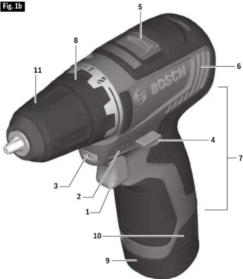
1 Variable speed trigger switch
2 Battery charge condition indicator lights
3 Built in work light
4 Forward/reversing lever and trigger lock
5 Gear selector
6 Ventilation openings
7 Rubberized grip (insulated gripping surface)
8 Adjustable clutch
9 Battery pack *
10 Battery release tabs
11 Keyless chuck
* Sold separately
Model number .....GSR12V-300
Voltage rating .....10.8V/12V MAX
No load speed 1....n00-460/min
No load speed 2....n00-1,750/min
Maximum Capacities
Chuck size ....3/8" (10mm)
Screw sizes .....5/16" (8mm)
Maximum drilling diameter
Mild metal ....3/8" (10mm)
Wood .....1-1/4" (32mm)
Allowed ambient temperature
- during charging . . . . . . .32...113 °F (0...+45 °C)
- during operation/
storage .....-4...122 °F (-20...+50 °C)
Battery Packs/Chargers
Please refer to the battery/charger list, included with your tool.
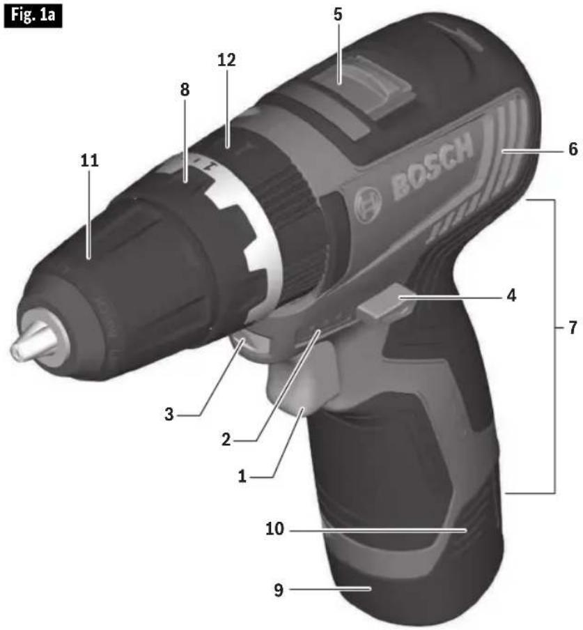
Functional Description and Specifications
Cordless Screwdriver GSR12V-300HX
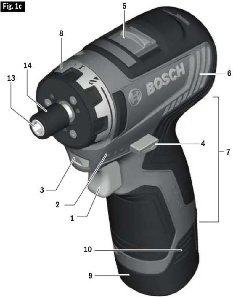
1 Variable speed trigger switch
2 Battery charge condition indicator lights
3 Built in work light
4 Forward/reversing lever and trigger lock
5 Gear selector
6 Ventilation openings
7 Rubberized grip (insulated gripping surface)
8 Adjustable clutch
9 Battery pack *
10 Battery release tabs
13 Hex drive
14 Locking sleeve
* Sold separately
Model number .....GSR12V-300HX
Voltage rating .....10.8V/12V MAX
No load speed 1....n00-460/min
No load speed 2....n00-1,750/min
Maximum Capacities
Hex drive ....1/4" (6.35mm) Hex-shank with power groove
Screw sizes .....5/16" (8mm)
Maximum drilling diameter
Mild metal ....3/8" (10mm)
Wood .....1-1/4" (32mm)
Allowed ambient temperature
- during charging . . . . . . .32...113 °F (0...+45 °C)
- during operation/
storage .....-4...122 °F (-20...+50 °C)
Battery Packs/Chargers
Please refer to the battery/charger list, included with your tool.
Assembly
WARNING
Disconnect battery pack from tool or place the switch in the locked or off position before making any assembly, adjustments or changing accessories.
Such preventive safety measures reduce the risk of starting the tool accidentally.
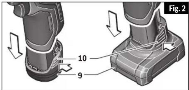
Inserting and Releasing Battery Pack
Release battery pack 9 from tool by pressing on both sides of the battery release tabs 10 and pull downward (Fig. 2). To insert battery, align battery and slide battery pack into tool until it locks into position. Do not force.
WARNING
If battery release tabs are cracked or
otherwise damaged, do not insert into tool. Battery can fall out during operation.
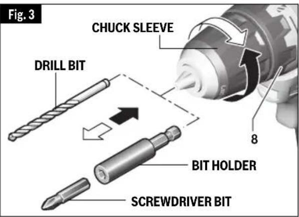
Inserting Bits
GSR12V-300 AND GSB12V-300
WARNING
Do not use the power of the drill while grasping
chuck to loosen or tighten bit. Friction burn or hand injury is possible if attempting to grasp the spinning chuck.
Move forward/reversing lever to the center "OFF" position. Remove battery pack and rotate the clutch ring 8 to the drill bit symbol "8" Rotate the chuck sleeve counter-clockwise viewing from chuck end, and open chuck to approximate drill bit diameter. Insert a clean bit up to the drill bit flutes for small bits, or as far as it will go for large bits. Close chuck by rotating the chuck sleeve clockwise and securely tighten by hand (Fig. 3).
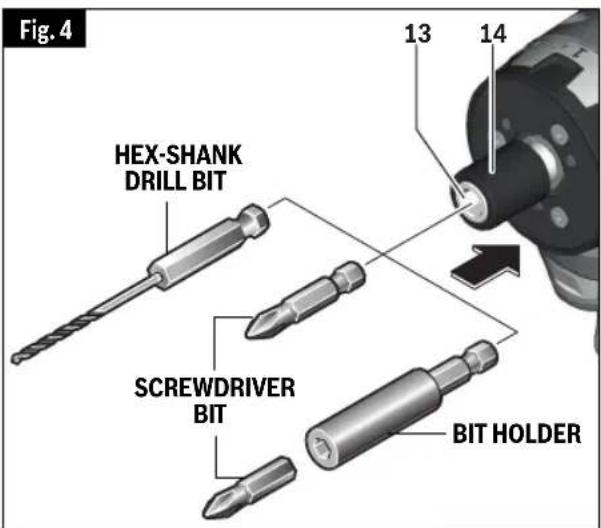
GSR12V-300HX
WARNING
To avoid loss of control, ensure bit is locked in
hex drive by pulling on bit after it has been inserted.
To insert an accessory, simply pull locking sleeve 14 backward, insert desired accessory into hex drive 13 until the locking sleeve retracts automatically, locking the bit (Fig. 4).
To remove an accessory, pull locking sleeve backward and simply remove it from the hex drive.
One inch bits should only be used along with a bit holder as shown in Fig. 4.
Assembly
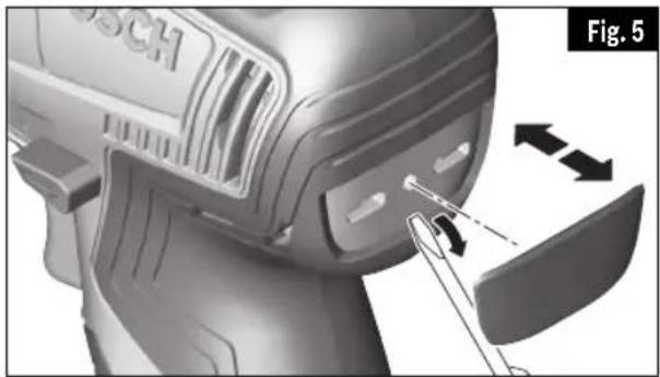
Belt Clip and Bit Tip Holder
These tools come with the option to use a metal belt clip or a four piece bit tip holder. Pry off the plastic cover from the back of the drill to install these accessories (Fig. 5).
BELT CLIP
WARNING
When the tool is attached to the belt,
position yourself to avoid entanglement with surrounding objects. Unexpected entanglement could cause the tool to fall resulting in injury to the operator or bystanders.
The belt clip will allow you to conveniently attach your tool to your belt. This feature will allow you to have both hands free when climbing a ladder or moving to another work area.
The belt clip can be positioned on either side of the tool and secured to the back of the tool with a mounting screw (Fig. 6). Always make sure you securely tighten the mounting screw before use.
To use the belt clip, point the chuck down and slide the clip over the belt.
4X BIT TIP HOLDER
WARNING
Only store short screwdriver bits in the
on-tool bit tip holder. Longer bits could interfere with proper tool operation and result in user injury.
The four piece bit tip holder can be used for convenient on tool storage of your most commonly used screw driving bits. Always make sure you securely tighten the mounting screw before use. (Fig. 6).
natural_image
Close-up of a Bosch electric shaver with tool interacting with a component (no visible text or symbols)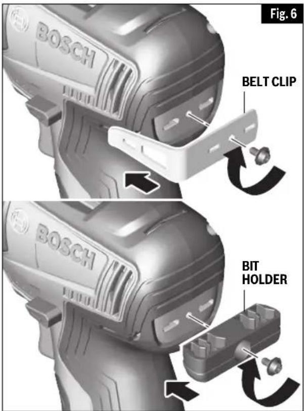
Operating Instructions
Protection against Deep Discharging
The lithium ion battery is protected against deep discharging by the “Electronic Cell Protection (ECP)”. When the battery is empty, the tool is switched off by means of a protective circuit.
Variable Speed Controlled Trigger Switch
Your tool is equipped with a variable speed trigger switch. The tool can be turned "ON" or "OFF" by squeezing or releasing the trigger. The speed can be adjusted from the minimum to maximum nameplate RPM by the pressure you apply to the trigger. Apply more pressure to increase the speed and release pressure to decrease speed (Fig. 1).
Brake
When the trigger switch is released it activates the brake to stop the chuck quickly. This is especially useful in the repetitive driving and removal of screws.
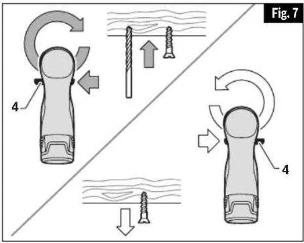
Forward/Reversing Lever and Trigger Lock
WARNING
After tool use, lock trigger in "OFF"
position to help prevent accidental starts and accidental discharge.
CAUTION
Do not change direction of rotation until the tool
comes to a complete stop. Shifting during rotation of the chuck can cause damage to the tool.
Your tool is equipped with a forward/reversing lever and trigger lock 4 located above the trigger (Fig. 7). This lever was designed for changing rotation of the bit, and for locking the trigger in an "OFF" position.
For forward rotation, (with chuck pointed away from you) move the lever to the far left.
For reverse rotation move the lever to the far right.
To lock the trigger in the "OFF" position, move the lever to the center.
Gear Shifting
Your tool is equipped with two separate gear ranges, low gear and high gear. Low gear provides high-torque and slower drilling speeds for heavy duty work or for driving screws. High gear provides faster speeds for drilling lighter work. To change speeds slide the gear selector 5, to the high position "2" or low position "1" (Fig. 1).
ATTENTION: If your tool appears to be running, but the chuck will not turn, check to make sure the gear selector is pushed fully into desired setting.
Adjustable Clutch
Your tool features 21 clutch settings. Output torque will increase as the clutch ring 8, is rotated from 1 to 20. The drill "E position will lock the clutch to permit drilling and driving heavy duty work (Fig. 1). Select the proper clutch setting for your application.
Drill/Hammer Drill/Driving Mode Selector ring
GSB12V-300 ONLY
The mode selector ring 12 allows the tool to be set for various drilling/hammer drilling and driving applications. Rotate the selector ring right or left depending on the below applications (Fig. 8).
Driving action: The driving position allows operation of adjustable clutch for driving screws and tightening nuts and bolts.
Operating Instructions
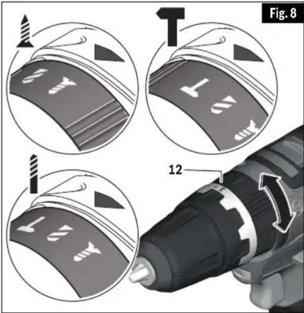
Drill only action: For drilling in woods, metals, plastics or other non concrete materials. The drill position overrides the clutch for drilling.
Drill with hammer action: For drilling in concrete, asphalt, tile or other similar hard materials. The hammer drill position overrides the clutch for hammer drilling.
Autolock™
Your tool is equipped with an automatic locking system. This feature will lock the bit holder in one position when the trigger switch is released. This will allow you to tighten or loosen a nut or screw by rotating the tool by hand with the switch off. This is convenient when higher turning torque is needed.
Built-in Work Light
Your tool is also equipped with a light that turns on automatically when the switch is activated, for better visibility when drilling/driving (Fig. 1).
Battery Charge Condition Indicator Lights
Your tool is equipped with charge condition indicator lights (Fig. 1). The indicator lights shows the charge condition of the battery for a few second when the On/Off trigger is pressed halfway or fully.
| LED | Capacity |
| Continuous lighting 3 x green | ≥ 76% |
| Continuous lighting 2 x green | 51–75% |
| Continuous lighting 1 x green | 26–50% |
| Flashing light 1 x green | ≤ 25% |
Operating Tips
You will extend the life of your bits and do neater work if you always put the bit in contact with the work before pulling the trigger. During the oper a tion, hold the tool firmly and exert light, steady pressure. Too much pressure at low speed will stall the tool. Too little pressure will keep the bit from cutting and cause excess friction by sliding over the surface. This can be damaging to both tool and bit.
DRIVING NUTS AND BOLTS
Variable speed control must be used with caution for driving nuts and bolts with socket set attach ments. The technique is to start slowly, increasing speed as the nut or bolt runs down. Set the nut or bolt snugly by slowing the drill to a stop. If this procedure is not followed, the tool will have a tendency to torque or twist in your hands when the nut or bolt seats.
DRILLING
You will extend the life of your bits and do neater work if you always put the bit in contact with the work before pulling the trigger. During the oper a tion, hold the tool firmly and exert light, steady pressure. Too much pressure at low speed will stall the tool. Too little pressure will keep the bit from cutting and cause excess friction by sliding over the surface. This can be damaging to both tool and bit.
DRILLING WITH VARIABLE SPEED
The switch trigger with variable speed adjustment helps in maintaining control of the tool. When the drill bit starts to remove material, speed of the drill bit may be increased by squeezing the trigger.
DRIVING WITH VARIABLE SPEED
Variable speed drills will double as a power screwdriver by using a screwdriver bit. Prior to driving screws, pilot and clearance holes should be drilled. Place the threaded end of the screw in the pilot or clearance
Operating Instructions
hole and start driving the screw slowly, increasing the speed as the screw runs down. Set the screw snugly by slowing to a stop.
FASTENING WITH SCREWS
The procedure shown in Fig. 9 will enable you to fasten materials together using your drill without stripping, splitting or separating the material.
First, clamp the pieces together and drill
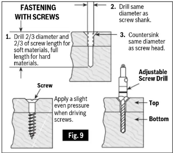
the hole 2/3 the diameter of the screw. If the material is soft, drill only 2/3 the proper length. If it is hard, drill the entire length.
Second, unclamp the pieces and drill the hole in the top piece of wood again to the same diameter as the shank of the screw.
Third, if flat head screw is used, countersink the hole to make the screw flush with the surface. Realign the holes on the two pieces and apply even pressure when driving the screw. The screw shank clearance hole in the first piece allows the screw head to pull the pieces tightly together.
The adjustable screw drill accessory will do all of these operations quickly and easily. Screw drills are available for screw sizes No. 6, 8, 10 and 12.
DRILL BITS
Always inspect drill bits for excessive wear. Use only bits that are sharp and in good condition.
TWIST BITS: Available with straight and
reduced shanks for wood and light duty metal drilling. High speed bits cut faster and last longer on hard materials.
CARBIDE TIPPED BITS: Used for drilling stone, con crete, plaster, cement and other unusually hard nonmetals. Use continuous heavy feed pres sure when employing carbide tip bits.
DRILLING WOOD
Be certain workpiece is clamped or anchored firmly. Always apply pressure in a straight line with the drill bit. Maintain enough pressure to keep the drill "biting".
When drilling holes in wood, twist bits can be used. Twist bits may overheat unless pulled out frequently to clear chips from flutes.
Use a “back-up” block of wood for work that is likely to splinter, such as thin materials.
You will drill a cleaner hole if you ease up on the pressure just before the bit breaks through the wood. Then complete the hole from the back side.
DRILLING METAL
There are two rules for drilling hard materials. First, the harder the material, the greater the pres sure you need to apply to the tool. Second, the harder the material, the slower the speed. Here are a couple of tips for drilling in metal. Lubri cate the tip of the bit occasionally with cutting oil except when drilling soft metals such as alu minum, cop per or cast iron. If the hole to be drilled is fairly large, drill a smaller hole first, then enlarge to the required size, it's often faster in the long run. Main tain enough pressure to assure that the bit does not just spin in the hole. This will dull the bit and greatly shorten its life.
DRILLING MASONRY
Soft materials such as brick are relatively easy to drill. Concrete however, will require much more pressure to keep the bit from spinning. Be sure to use carbide tip bits for all masonry work.
Maintenance
WARNING
To avoid accidents, always disconnect the tool and/or charger from the power supply before servicing or cleaning.
Service
WARNING
NO USER SERVICE ABLE PARTS INSIDE.
Preventive maintenance performed by un - authorized personnel may result in misplacing of internal wires and components which could cause serious hazard. We recommend that all tool service be performed by a Bosch Factory Service Center or Authorized Bosch Service Station. SERVICE MEN: Disconnect tool and/or charger from power source before servicing.
Batteries
Be alert for battery packs that are nearing their end of life. If you notice decreased tool performance or significantly shorter running time between charges then it is time to replace the battery pack. Failure to do so can cause the tool to operate improperly or damage the charger.
Tool Lubrication
Your Bosch tool has been properly lubricated and is ready for use.
Motors
The motor in your tool has been engineered for many hours of dependable service. To maintain peak efficiency of the motor, we recommend it be examined every six months. Only a genuine Bosch replacement motor specially designed for your tool should be used.
Cleaning
CAUTION
Certain cleaning agents and solvents damage
plastic parts. Some of these are: gasoline, carbon tetrachloride, chlorinated cleaning solvents, ammonia and household detergents that contain ammonia.
Ventilation openings and switch levers must be kept clean and free of foreign matter. Do not attempt to clean by inserting pointed objects through opening.
Taux de percussion .....26250 b/mn
Capacités maximales
Dimension de mandrin ...3/8 po (10 mm)
Tailles de vis ....5/16 po (8 mm)
natural_image
Close-up of a Bosch electric shaver with tool interacting with the blade (no text or symbols visible)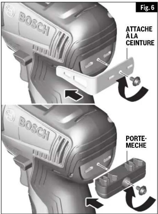
natural_image
Close-up of a Bosch electric shaver with a tool inserted, showing mechanical components and motion arrows (no text or symbols)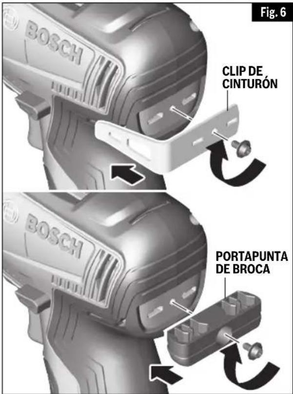
Robert Bosch Tool Corporation ("Seller") warrants to the original purchaser only, that all BOSCH portable and benchtop power tools will be free from defects in material or workmanship for a period of one year from date of purchase. SELLER'S SOLE OBLIGATION AND YOUR EXCLUSIVE REMEDY under this Limited Warranty and, to the extent permitted by law, any warranty or condition implied by law, shall be the repair or replacement of parts, without charge, which are defective in material or workmanship and which have not been misused, carelessly handled, or misrepaired by persons other than Seller or Authorized Service Station. To make a claim under this Limited Warranty, you must return the complete portable or benchtop power tool product, transportation prepaid, to any BOSCH Factory Service Center or Authorized Service Station. For Authorized BOSCH Power Tool Service Stations, please refer to your phone directory.
THIS LIMITED WARRANTY DOES NOT APPLY TO ACCESSORY ITEMS SUCH AS CIRCULAR SAW BLADES, DRILL BITS, ROUTER BITS, JIGSAW BLADES, SANDING BELTS, GRINDING WHEELS AND OTHER RELATED ITEMS.
ANY IMPLIED WARRANTIES SHALL BE LIMITED IN DURATION TO ONE YEAR FROM DATE OF PURCHASE. SOME STATES IN THE U.S., SOME CANADIAN PROVINCES DO NOT ALLOW LIMITATIONS ON HOW LONG AN IMPLIED WARRANTY LASTS, SO THE ABOVE LIMITATION MAY NOT APPLY TO YOU.
IN NO EVENT SHALL SELLER BE LIABLE FOR ANY INCIDENTAL OR CONSEQUENTIAL DAMAGES (INCLUDING BUT NOT LIMITED TO LIABILITY FOR LOSS OF PROFITS) ARISING FROM THE SALE OR USE OF THIS PRODUCT. SOME STATES IN THE U.S. AND SOME CANADIAN PROVINCES DO NOT ALLOW THE EXCLUSION OR LIMITATION OF INCIDENTAL OR CONSEQUENTIAL DAMAGES, SO THE ABOVE LIMITATION OR EXCLUSION MAY NOT APPLY TO YOU.
THIS LIMITED WARRANTY GIVES YOU SPECIFIC LEGAL RIGHTS, AND YOU MAY ALSO HAVE OTHER RIGHTS WHICH VARY FROM STATE TO STATE IN THE U.S., PROVINCE TO PROVINCE IN CANADA AND FROM COUNTRY TO COUNTRY.
THIS LIMITED WARRANTY APPLIES ONLY TO PORTABLE AND BENCHTOP ELECTRIC TOOLS SOLD WITHIN THE UNITED STATES OF AMERICA, CANADA AND THE COMMONWEALTH OF PUERTO RICO. FOR WARRANTY COVERAGE WITHIN OTHER COUNTRIES, CONTACT YOUR LOCAL BOSCH DEALER OR IMPORTER.
GARANTIE LIMITÉE DES OUTILS ÉLECTRIQUES PORTATIFS ET D'ÉTABLI BOSCH
© Robert Bosch Tool Corporation 1800 W. Central Road Mt. Prospect, IL 60056-2230
Exportado por: Robert Bosch Tool Corporation Mt. Prospect, IL 60056-2230, E.U.A.