
GCL 250 CG Professional - Laser pointer BOSCH - Free user manual and instructions
Find the device manual for free GCL 250 CG Professional BOSCH in PDF.
| Brand | Bosch |
| Model | GCL 250 CG Professional |
| Category | Laser pointer |
| Laser type | Green (500‑540 nm, < 10 mW) for lines; Red (630‑650 nm, < 1 mW) for points |
| Laser class | 2 |
| Laser line range (standard) | 20 m |
| Range with receiver cell | 5–50 m |
| Plumb point range | 10 m (top and bottom) |
| Leveling accuracy (lines) | ±0.3 mm/m |
| Leveling accuracy (points) | ±0.7 mm/m |
| Self‑leveling range | ±4° |
| Leveling time | < 4 s |
| Power supply | Lithium‑ion battery 10.8 V / 12 V (GBA 12V…) or 4 LR6 (AA) batteries |
| Run time (point and cross line mode) | 10 h (battery) / 4 h (batteries) |
| Dimensions (without bracket) | 136 × 55 × 122 mm |
| Weight (with battery) | 0.62 kg |
| Protection rating | IP54 (dust‑proof and splash‑proof) |
| Operating temperature | −10 °C to +50 °C |
| Bluetooth® | 4.2 (Classic & Low Energy) – remote control via Bosch app |
| Main functions | Horizontal and vertical lines, plumb points, cross line mode, point mode |
| Swivel mount included | 360° rotation, magnets, micrometer screw, wall mounting |
| Care and cleaning | Clean with a soft, damp cloth; do not use solvents; do not immerse |
| Safety | Do not look into the laser beam; use in non‑explosive atmosphere; observe warnings |
| Spare parts and repairability | Spare parts available through Bosch service; repair by an authorized professional |
| General information | User manual downloadable as PDF from notice‑facile.com |
Frequently Asked Questions - GCL 250 CG Professional BOSCH
User questions about GCL 250 CG Professional BOSCH
0 question about this device. Answer the ones you know or ask your own.
Ask a new question about this device
Download the instructions for your Laser pointer in PDF format for free! Find your manual GCL 250 CG Professional - BOSCH and take your electronic device back in hand. On this page are published all the documents necessary for the use of your device. GCL 250 CG Professional by BOSCH.
USER MANUAL GCL 250 CG Professional BOSCH
Bmu Fredetti has maliat ulasitas
ru OOhnuaHoe DvKOBcCTaDC
AKTINYSLALUKA
uk CoHrHaBb HcTpyKjE 3
ekzryataa
kkTnndnanyHcKAYDfEHsH
TYNNYCKACs
ro InstruetiOn
bgComnHAnHaHnCTpyKp
MKOPAHHHOY130
srOriginalng uotstvo zara
sl Izyma pavodla
by Original up
YkpaIHcbKa ..CtoPiHa 201
Kaazak. 5er 213
Romana.. .Pagina 224
Блгарский.. ..Ctpanua 235
MaKeDoHcKn. CtrpaHua 246
Srpski Strana 257
Slovenscina Stran 268
Download on the App Store

GET IT ON Google Play
www.bosch-pt.com/serviceaddresses
Transport
All instructions must be read and observed in order for the measuring tool to function safely. The safeguards integrated into the measuring tool may be compromised if the
measuring tool is not used in accordance with these instructions. Never make warning signs on the measuring tool unrecognisable. SAVE THESE INSTRUCTIONS FOR FUTURE REFERENCE AND INCLUDE THEM WITH THE MEASURING TOOL WHEN TRANSFERRING IT TO A THIRD PARTY.
Warning! If operating or adjustment devices other than those specified here are used or other procedures are carried out, this can lead to dangerous exposure to radiation.
The measuring tool is delivered with a laser warning sign (marked in the illustration of the measuring tool on the graphics page).
If the text of the laser warning label is not in your national language, stick the provided warning label in your national language over it before operating for the first time.

Do not direct the laser beam at persons or animals and do not stare into the direct or reflected laser beam yourself. You could blind somebody, cause accidents or damage your eyes.
If laser radiation hits your eye, you must close your eyes and immediately turn your head away from the beam.
Do not make any modifications to the laser equipment.
- Do not use the laser goggles (accessory) as protective goggles. The laser goggles make the laser beam easier to see; they do not protect you against laser radiation.
Do not use the laser goggles (accessory) as sunglasses or while driving. The laser goggles do not provide full UV protection and impair your ability to see colours.
Have the measuring tool serviced only by a qualified specialist using only original replacement parts. This will ensure that the safety of the measuring tool is maintained.
Do not let children use the laser measuring tool unsupervised. They could unintentionally blind themselves or other persons.
Do not use the measuring tool in explosive atmospheres which contain flammable liquids, gases or dust. Sparks may be produced inside the measuring tool, which can ignite dust or fumes.
Do not open the battery. There is a risk of short-circuiting.
In case of damage and improper use of the battery, vapours may be emitted. The battery can set alight or explode. Ensure the area is well ventilated and seek medical attention should you experience any adverse effects. The vapours may irritate the respiratory system.
If used incorrectly or if the battery is damaged, flammable liquid may be ejected from the battery. Contact with this liquid should be avoided. If contact accidentally occurs, rinse off with water. If the liquid comes into contact with your eyes, seek additional medical attention. Liquid ejected from the battery may cause irritation or burns.
The battery can be damaged by pointed objects such as nails or screwdrivers or by force applied externally. An internal short circuit may occur, causing the battery to burn, smoke, explode or overheat.
- When the battery is not in use, keep it away from paper clips, coins, keys, nails, screws or other small metal objects that could make a connection from one terminal to another. A short circuit between the battery terminals may cause burns or a fire.
Only use the battery with products from the manufacturer. This is the only way in which you can protect the battery against dangerous overload.
Only charge the batteries using chargers recommended by the manufacturer. A charger that is suitable for one type of battery may pose a fire risk when used with a different battery.


Protect the battery against heat, e.g. against continuous intense sunlight, fire, dirt, water and moisture. There is a risk of explosion and short-circuiting.
Keep the measuring tool and the magnetic accessories away from implants and other medical devices, e.g. pacemakers or insulin pumps. The magnets inside the measuring tool and accessories generate a field that can impair the function of implants and medical devices.
- Keep the measuring tool and the magnetic accessories away from magnetic data storage media and magnetically sensitive devices. The effect of the magnets inside the measuring tool and accessories can lead to irreversible data loss.
- Remove the rechargeable battery/non-rechargeable batteries from the measuring tool before carrying out work on the measuring tool (e.g. assembly, maintenance, etc.). The battery/batteries should also be removed for transport and storage. There is risk of injury from unintentionally pressing the on/off switch.
Caution! When using the measuring tool with Bluetooth, a fault may occur in other devices and systems, aeroplanes and medical devices (e.g. pacemakers, hearing aids). Also, damage to people and animals in the immediate vicinity cannot be completely excluded. Do not use the measuring tool with Bluetooth in the vicinity of medical devices, petrol stations, chemical plants, areas with a potentially explosive atmosphere and in blasting areas. Do not use the measuring tool with Bluetooth on aeroplanes. Avoid using the product near your body for extended periods.
The Bluetooth® word mark and logos are registered trademarks owned by Bluetooth SIG, Inc. and any use of such marks by Robert Bosch Power Tools GmbH is under license.
Product Description and Specifications
Please observe the illustrations at the beginning of this operating manual.
Intended Use
The measuring tool is intended for determining and checking horizontal and vertical lines and plumb points.
The measuring tool is suitable for indoor and outdoor use.
You can use the RM 2 rotating mount to rotate the measuring tool 360^ around a central, always visible plumb point. This enables you to align the laser lines precisely, without having to change the position of the measuring tool.
Product Features
The numbering of the product features shown refers to the illustration of the measuring tool on the graphic page.
(1) Guide groove
(2) On/off switch
(3) Laser beam outlet aperture
(4) State of charge of rechargeable battery/non-rechargeable batteries
(5) Pendulum lock indicator
(6) Receiver mode button
(7) Receiver mode indicator
(8) Button for laser operating mode
(9) Bluetooth® connection indicator
(10)Bluetooth® button
(11) Battery bay
(12) Rechargeable battery
(13) Battery adapter cover
(14) Non-rechargeable batteriesa
(15) Rechargeable battery/chargeable battery adapter release button
(16) Battery adapter sealing cap
(17) Laser warning label
(18) 1 / 4 tripod mount
(19) Serial number
(20) Guide rai[a]
(21) Magnet
(22) Fastening slot
(23) Rotating mount
(24) Fine adjustment screw of the rotating mounta
(25) Ceiling clipa)
(26) Universal holder
(27) Rotating platform
(28) Remote control
(29) Laser receiver
(30) Laser viewing glassesa
(31) Laser target plate
(32) Tripodal
(33) Telescopic roof
(34) Protective bag
(35) Battery adapter
(36) Casea
a) Accessories shown or described are not included with the product as standard. You can find the complete selection of accessories in our accessories range.
Technical Data
Point and line laser GCL 2-50 C GCL 2-50 CG
| Article number | 3601 K66 G.. 3601 K66 H.. |
| Working rangeA) | |
| - Standard laser lines 20 m 20 m | |
| - With laser receiver 5-50 m 5-50 m | |
22 | English
Point and line laser GCL 2-50 C GCL 2-50 CG
| - Laser point facing up 10 m 10 m | ||
| - Laser point facing down 10 m 10 m | ||
| Levelling accuracy\(^{B(C)}\) | ||
| -Laser lines ±0.3 mm/m ±0.3 mm/m | ||
| -Laser points ±0.7 mm/m ±0.7 mm/m | ||
| Typical self-levelling range ±4° ±4° | ||
| Typical levelling time < 4 s < 4 s | ||
| Max. altitude 2000 m 2000 m | ||
| Relative air humidity max. 90 % 90 % | ||
| Pollution degree according to IEC 61010-1 | \(2^{D)}\) | \(2^{D)}\) |
| Laser class | 2 | 2 |
| Pulse frequency | ||
| - Operating without receiver mode | 23 kHz | 23 kHz |
| - Operating with receiver mode | 10 kHz | 10 kHz |
| Laser line | ||
| -Laser type | 630-650 nm, < 10 mW | 500-540 nm, < 10 mW |
| -Colour of the laser beam | Red | Green |
| -\(C_6\) | 10 | 10 |
| -Divergence | 50 × 10 mrad (full angle) | 50 × 10 mrad (full angle) |
| Laser point | ||
| -Laser type | 630-650 nm, < 1 mW | 630-650 nm, < 1 mW |
| -Colour of the laser beam | Red | Red |
| -\(C_6\) | 1 | 1 |
| -Divergence | 0.8 mrad (full angle) | 0.8 mrad (full angle) |
| Compatible laser receivers | LR 6, LR 7 | LR 7 |
| Tripod mount | 1/4" | 1/4" |
| Power supply | ||
| -Rechargeable battery (Li-ion) | 10.8 V/12 V | 10.8 V/12 V |
| -Non-rechargeable batteries (al-kaline manganese) | 4 × 1.5 V LR6 (AA) (with battery adapter) | 4 × 1.5 V LR6 (AA) (with battery adapter) |
| Operating duration in operating mode\(^{B(E)}\) | Rechargeable battery/non-rechargeable batteries | Rechargeable battery/non-rechargeable batteries |
| -Cross-line and point mode | 18 h/10 h | 10 h/4 h |
| -Cross-line mode | 25 h/16 h | 13 h/6 h |
| -Line mode | 35 h/28 h | 15 h/12 h |
| -Point mode | 60 h/32 h | 60 h/32 h |
| Bluetooth® measuring tool | ||
| -Compatibility | Bluetooth® 4.2 (Classic and Low Energy)\(^{F)}\) | Bluetooth® 4.2 (Classic and Low Energy)\(^{F)}\) |
| -Operating frequency range | 2402-2480 MHz | 2402-2480 MHz |
| -Max. transmission power | 2.5 mW | 2.5 mW |
| Bluetooth® smartphone | ||
| -Compatibility | Bluetooth® 4.0 (Classic and Low Energy)\(^{F)}\) | Bluetooth® 4.0 (Classic and Low Energy)\(^{F)}\) |
| -Operating system | Android 6 (and above)iOS 11 (and above) | Android 6 (and above)iOS 11 (and above) |
Point and line laser GCL 2-50 C GCL 2-50 CG
| Weight according to EPTA-Procedure 01:2014 | ||
| – With rechargeable batteryG) | 0.62 kg 0.62 kg | |
| – With non-rechargeable batteries 0.58 kg 0.58 kg | ||
| Dimensions (length × width × height) | ||
| – Without holder 136 × 55 × 122 mm 136 × 55 × 122 mm | ||
| – With rotating mount Dia.: 188 × 180 mm Dia.: 188 × 180 mm | ||
| Protection ratingH) | IP 54 (dust and splash-proof) IP 54 (dust and splash-proof) | |
| Recommended ambient temperature during charging | 0°C ... +35°C 0°C ... +35°C | |
| Permitted ambient temperature during operation | -10°C ... +50°C -10°C ... +50°C | |
| Permitted ambient temperature during storage | -20°C ... +70°C -20°C ... +70°C | |
| Recommended rechargeable batteries GBA 12V... | (except for GBA 12V ≥ 4.0 Ah) | GBA 12V... |
| (except for GBA 12V ≥ 4.0 Ah) | ||
| Recommended chargers GAL 12... | GAX 18... | GAL 12... |
| GAX 18... | ||
A) The working range may be reduced by unfavourable environmental conditions (e.g. direct sunlight).
B) At 20-25°C
C) The values stated presuppose normal to favourable environmental conditions (e.g. no vibration, no fog, no smoke, no direct sunlight). Extreme fluctuations in temperature can cause deviations in accuracy.
D) Only non-conductive deposits occur, whereby occasional temporary conductivity caused by condensation is expected.
E) Shorter operating times in Bluetooth® operation and/or in conjunction with RM 3
F) When using Bluetooth® Low Energy devices, it may not be possible to establish a connection depending on the model and operating system. Bluetooth® devices must support the SPP profile.
G) Depends on battery in use
H) The lithium-ion battery and the AA1 battery adapter are excluded from IP 54.
Technical data determined using the battery that comes with the product.
The serial number (19) on the type plate is used to clearly identify your measuring tool.
Assembly
Measuring Tool Power Supply
The measuring tool can be operated either with conventional non-rechargeable batteries or with a Bosch lithium-ion battery.
Operation with Rechargeable Battery
Use only the chargers listed in the technical data. Only these chargers are matched to the lithium-ion battery of your measuring tool.
Note: The use of batteries unsuitable for your measuring tool can lead to malfunctions or damage to the measuring tool.
Note: The battery is supplied partially charged. To ensure full battery capacity, fully charge the battery in the charger before using your tool for the first time.
The lithium-ion battery can be charged at any time without reducing its service life. Interrupting the charging process does not damage the battery.
The lithium-ion battery is protected against deep discharge by the "Electronic Cell Protection (ECP)". A protective circuit switches the measuring tool off when the battery is drained.
Do not switch the measuring tool back on after it has been switched off by the protective circuit. This can damage the battery.
To insert the charged battery (12), slide it into the battery bay (11) until you feel it engage.
To remove the battery (12), press the release buttons (15) and pull it out of the battery bay (11). Do not use force to do this.
Operation with Non-Rechargeable Batteries
It is recommended that you use alkaline manganese batteries to operate the measuring tool.
The batteries are inserted into the battery adapter.
The battery adapter is intended only for use in designated Bosch measuring tools and must not be used with power tools.
To insert the batteries, slide the cover (13) of the battery adapter into the battery bay (11). Place the batteries into the cover as per the illustration on the sealing cap (16).
Slide the sealing cap over the cover until you feel it click into place.

To remove the batteries (14), press the release buttons (15) of the sealing cap (16) and pull off the sealing cap. Make sure that the batteries do not fall out. To do this, hold the measuring tool with the battery bay (11) facing up
ward. Remove the batteries. To remove the cover (13) from inside the battery bay, reach into the cover and pull it out of the measuring tool, applying light pressure to the side wall as you do so.
Always replace all the batteries at the same time. Only use batteries from the same manufacturer and which have the same capacity.
Take the batteries out of the measuring tool when you are not using it for a prolonged period of time. The batteries can corrode and self-discharge during prolonged storage in the measuring tool.
Battery Charge Indicator
The battery charge indicator (4) shows the state of charge of the rechargeable battery/non-rechargeable batteries:
LED State of charge
Green continuous light 100-75%
Yellow continuous light 75-35%
Red flashing light < 35%
No light - Rechargeable battery defective
Non-rechargeable batteries drained
If the rechargeable battery or non-rechargeable batteries are running low, the laser lines will gradually become dimmer. Immediately replace a faulty rechargeable battery or any empty batteries.
Working with the RM 2 rotating mount (see figures A1-A3)
You can use the rotating mount (23) to rotate the measuring tool 360^ around a central, always visible plumb point. This enables you to set up the laser lines without having to change the position of the measuring tool.
You can use the fine adjustment screw (24) to align vertical laser lines precisely with reference points.
Place the measuring tool with the guide groove (1) on the guide rail (20) of the rotating mount (23) and slide the measuring tool all the way onto the platform.
To disconnect the measuring tool, pull it off the rotating mount in the opposite direction.
Rotating mount positioning options:
- Standing on a flat surface,
Screwed to a vertical surface, - On metallic ceiling strips using the ceiling clip (25),
- On metallic surfaces using the magnets (21).
Operation
Starting Operation
Protect the measuring tool from moisture and direct sunlight.
Do not expose the measuring tool to any extreme temperatures or fluctuations in temperature. For example, do not leave it in a car for extended periods of time. If it has been subjected to significant fluctuations in temperature, first allow the measuring tool to adjust to the ambient temperature and then always carry out an accuracy check before continuing work (see "Accuracy Check of the Measuring Tool", page 26).
The precision of the measuring tool may be compromised if exposed to extreme temperatures or fluctuations in temperature.
- Avoid substantial knocks to the measuring tool and avoid dropping it. Always carry out an accuracy check before continuing work if the measuring tool has been subjected to severe external influences (see "Accuracy Check of the Measuring Tool", page 26).
Switch the measuring tool off when transporting it.
The pendulum unit is locked when the tool is switched off, as it can otherwise be damaged by big movements.
Switching On/Off
To switch on the measuring tool, slide the on/off switch (2) to the on position (for working with the pendulum lock) or to the on position (for working with automatic levelling). As soon as it is switched on, the measuring tool emits laser beams from the outlet apertures (3).
Do not direct the laser beam at persons or animals and do not stare into the laser beam yourself (even from a distance).
To switch off the measuring tool, slide the on/off switch (2) to the Off position. The pendulum unit is locked when the tool is switched off.
Never leave the measuring tool unattended when switched on, and ensure the measuring tool is switched off after use. Others may be blinded by the laser beam.
If the maximum permitted operating temperature of 50^ is exceeded, the tool shuts down to protect the laser diode. Once it has cooled down, the measuring tool is operational again and can be switched back on.
Automatic Shut-Off
If no button on the measuring tool is pressed for approx. 120 min, the measuring tool will automatically switch itself off to preserve battery life.
To switch the measuring tool back on after it has been automatically switched off, you can either slide the on/off switch (2) to the "Off" position first and then switch the measuring tool back on, or press the laser operating mode button (8).
Temporarily Deactivating Automatic Shut-Off
To deactivate the automatic shut-off function, hold down the laser mode button (8) for at least 3 s (with the measuring tool switched on). If the automatic shut-off function is deactivated, the laser beams will flash briefly as confirmation.
Note: If the operating temperature exceeds 45^ , automatic shut-off can no longer be deactivated.
To activate the automatic shut-off function, switch the measuring tool off and on again.
Setting the Operating Mode
The measuring tool has several operating modes, which you can switch between at any time:
Cross-line and point mode: The measuring tool generates a horizontal and a vertical laser line as well as two vertical laser points, one facing up, the other down. The laser lines cross at a 90^ angle.
Horizontal line mode: The measuring tool generates a horizontal laser line in front of it.
Vertical line mode: The measuring tool generates a vertical laser line in front of it. Positioning the measuring tool in the room displays the vertical laser line on the ceiling beyond the top laser point.
If the measuring tool is positioned directly against a wall, the vertical laser line almost encircles the entire space (360^ line).
- Point mode: The measuring tool generates two vertical laser points, one facing up, the other down.
All operating modes, apart from point operation, can be selected with both automatic levelling or the pendulum lock. To change the operating mode, press the laser mode button (8).
Working with Automatic Levelling
| Sequence of actions Horizontal line | mode | Vertical line mode | Point mode Pendulum lock indicator (5) | Figure | |
| On/off switch (2) in position "on" | ●●● | Cross-line mode | □ | B | |
| Laser | Press the laser operating mode button (8) once | ●-- | □ | C | |
| Laser | Press the laser operating mode button (8) twice | -●- | □ | D | |
| Laser | Press the laser operating mode button (8) three times | -● | □ | E | |
| Laser | Press the laser operating mode button (8) four times | ●●● | Cross-line mode | □ | B |
If, during work with automatic levelling, you switch to "working with pendulum lock" mode (on/off switch (2) in position
On), the first combination option of this mode's indicators is always activated.
Working with the pendulum lock
| Sequence of actions Horizontal line | mode | Vertical line mode | Point mode Pendulum lock indicator (5) | Figure | |
| On/off switch (2) in position "On" | ●●- | Red | F | ||
| Cross-line mode | |||||
| Laser | Press the laser operating mode button (8) once | ●-● | Red | ||
| Laser | Press the laser operating mode button (8) twice | -●- | Red | ||
| Laser | Press the laser operating mode button (8) three times | ●●- | Red | F | |
| Cross-line mode | |||||
If, during work with pendulum lock, you switch to "working with automatic levelling" mode (on/off switch (2) in position On), the first combination option of this mode's indicators is always activated.
Receiver Mode
Receiver mode must be activated when working with the laser receiver (29), regardless of which operating mode is selected.
26|English
In receiver mode, the laser lines flash at a very high frequency, enabling them to be detected by the laser receiver (29).
To switch on receiver mode, press the receiver mode button (6). The receiver mode indicator (7) will light up green.
When receiver mode is switched on, the laser lines are less visible to the human eye. Therefore, switch receiver mode off by pressing the receiver mode button (6) again to work without a laser receiver. The receiver mode indicator (7) will go out.
Automatic Levelling
Working with Automatic Levelling (see figures B-E)
Position the measuring tool on a level, firm surface or attach it to the rotating mount (23).
For work with automatic levelling, slide the on/off switch (2) to the "On" position.
The automatic levelling function automatically levels irregularities within the self-levelling range of ± 4^ . The measuring tool has been levelled as soon as the laser beams stop flashing.
If automatic levelling is not possible, e.g. because the surface on which the measuring tool stands deviates by more than 4^ from the horizontal plane, the laser beams will flash quickly.
If this is the case, set up the measuring tool in a level position and wait for the self-levelling to take place. As soon as the measuring tool is within the self-levelling range of ± 4^ , the laser beams will light up continuously.
In case of ground vibrations or position changes during operation, the measuring tool is automatically levelled again. Upon levelling, check the position of the laser beams with regard to the reference points to avoid errors arising from a change in the measuring tool's position.
Working with a pendulum lock (see figure F)
For work with the pendulum lock, slide the on/off switch (2) to the "On" position. The pendulum lock indicator (5)
lights up red and the laser lines continuously flash slowly. For work with the pendulum lock, automatic levelling is switched off. You can hold the measuring tool freely in your hand or place it on a sloping surface. This means that the laser beams are no longer levelled and no longer necessarily run perpendicular to one another.
Remote control via Bluetooth®
The measuring tool is equipped with a Bluetooth® module which uses radio technology to enable remote control via a smartphone with a Bluetooth® interface.
Information about the system requirements for a Bluetooth® connection can be found on the Bosch website at www.bosch-pt.com
When remote controlling via Bluetooth, poor reception conditions can cause time delays between the mobile terminal device and the measuring tool.
Bosch applications (apps) are available for remote controlling. They can be downloaded in the respective stores, depending on the terminal/device:

Download on the App Store

GET IT ON Google Play
Switching on Bluetooth®
To switch on Bluetooth®, press the Bluetooth® button (10). Ensure that the Bluetooth® interface is activated on your mobile terminal device.
The connection between mobile end device and measuring tool is established after the Bosch application has started. If multiple active measuring tools are found, select the appropriate measuring tool. A connection will be established automatically if only one active measuring tool is found.
The connection is established as soon as the Bluetooth® indicator (9) lights up.
The Bluetooth® connection may be interrupted if the distance between the measuring tool and the mobile terminal device is too great or is blocked, and if there are any sources of electromagnetic interference. Should this occur, the Bluetooth® indicator (9) will flash.
Switching off Bluetooth®
To switch off Bluetooth® for remote control, press the Bluetooth® button (10) or switch off the measuring tool.
Accuracy Check of the Measuring Tool
Influences on Accuracy
The largest influence is exerted by the ambient temperature. In particular, temperature differences that occur from the ground upwards can refract the laser beam.
Since the temperature stratification is greatest at ground level, you should always mount the measuring tool on a tripod for measuring distances of 20m or more. In addition, position the measuring tool in the centre of the work surface, wherever this is possible.
In addition to external influences, device-specific influences (e.g. falls or heavy impacts) can also lead to deviations. For this reason, check the levelling accuracy each time before beginning work.
First check the height accuracy and levelling accuracy of the horizontal laser line, then the levelling accuracy of the vertical laser line and the plumb accuracy.
Should the measuring tool exceed the maximum deviation during one of the tests, please have it repaired by a Bosch after-sales service.
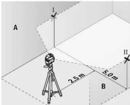
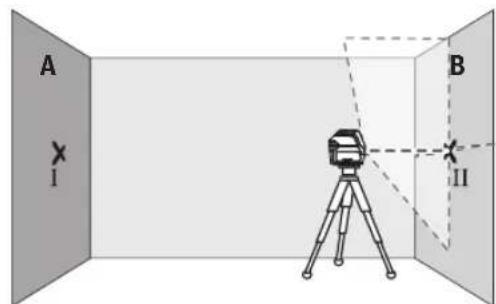
Checking the Height Accuracy of the Horizontal Line
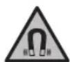
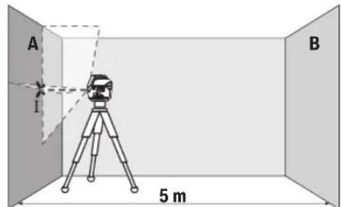
For this check, you will need a free measuring distance of 5 m on firm ground between two walls (designated A and B).
- Mount the measuring tool close to wall A on a tripod, or place it on a firm, level surface. Switch on the measuring tool. Select cross-line mode with automatic levelling.
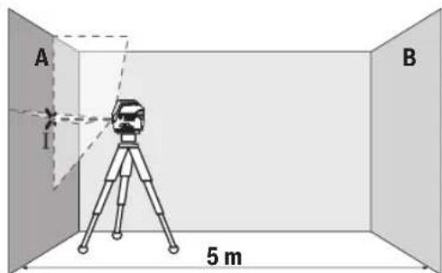
- Aim the laser at the closer wall A and allow the measuring tool to level in. Mark the middle of the point at which the laser lines cross on the wall (point I).
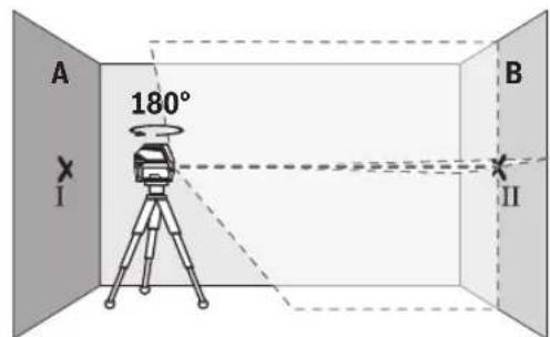
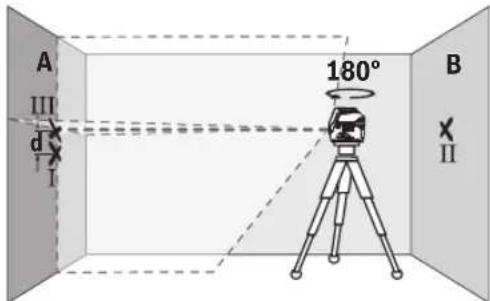
- Turn the measuring tool 180^ , allow it to level in and mark the point where the laser lines cross on the opposite wall B (point II).
- Position the measuring tool - without rotating it - close to wall B, switch it on and allow it to level in.

Align the height of the measuring tool (using the tripod or by placing objects underneath as required) so that the point where the laser lines cross exactly hits the previously marked point II on wall B.

- Turn the measuring tool 180^ without adjusting the height. Aim it at wall A such that the vertical laser line runs through the already marked point I. Allow the measuring tool to level in and mark the point where the laser lines cross on wall A (point III).
- The discrepancy d between the two marked points I and III on wall A reveals the actual height deviation of the measuring tool.
The maximum permitted deviation on the measuring distance of 2 × 5m = 10m is as follows:
10 m × ±0.3 mm/m = ±3 mm. The discrepancy d between points I and III must therefore amount to no more than 3 mm.
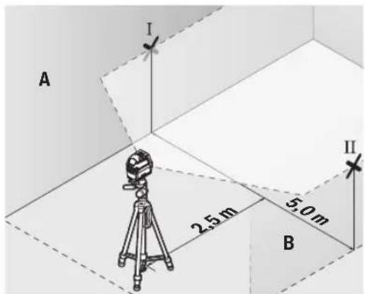
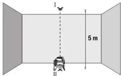
Checking the Level Accuracy of the Horizontal Line
For this check, you will need a free area of 5 × 5 m.
- Mount the measuring tool in the middle between walls A and B on a tripod, or place it on a firm, level surface. Select horizontal line mode with automatic levelling and allow the measuring tool to level in.
- At a distance of 2.5m from the measuring tool, mark the centre of the laser line on both walls (point I on wall A and point II on wall B).
28|English
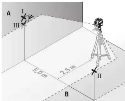
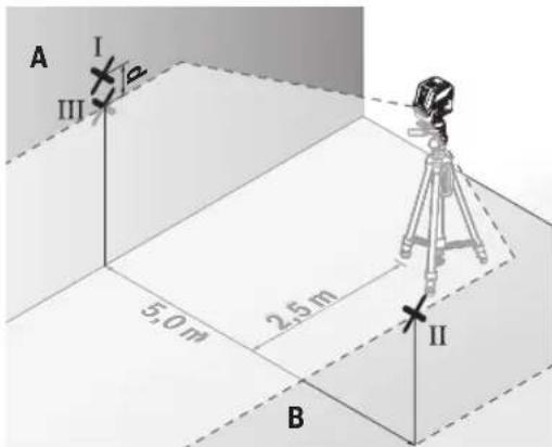
- Set up the measuring tool at a 5 m distance and rotated by 180^ and allow it to level in.
Align the height of the measuring tool (using the tripod or by placing objects underneath as required) so that the centre of the laser line exactly hits the previously marked point II on wall B. - Mark the centre of the laser line on wall A as point III (vertically above or below point I).
- The discrepancy d between the two marked points I and III on wall A reveals the actual horizontal deviation of the measuring tool.
The maximum permitted deviation on the measuring distance of 2 × 5m = 10m is as follows:
10 m × ±0.3 mm/m = ±3 mm. The discrepancy d between points I and III must therefore amount to no more than 3 mm.
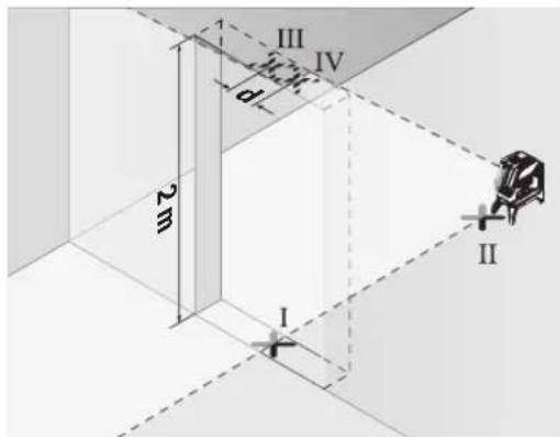
Checking the Level Accuracy of the Vertical Line
For this check, you will need a door opening (on solid ground) which has at least 2.5m of space either side of the door.
- Place the measuring tool 2.5m away from the door opening on a firm, flat surface (not on a tripod). Select vertical line mode with automatic levelling. Aim the laser line at the door opening and allow the measuring tool to level in.

- Mark the centre of the vertical laser line on the floor of the door opening (point I), 5 m away on the other side of the door opening (point II) and on the upper edge of the door opening (point III).

- Rotate the measuring tool 180^ and position it on the other side of the door opening, directly behind point II. Allow the measuring tool to level in and align the vertical laser line in such a way that its centre passes through points I and II exactly.
- Mark the centre of the laser line on the upper edge of the door opening as point IV.
- The discrepancy d between the two marked points III and IV reveals the actual vertical deviation of the measuring tool.
- Measure the height of the door opening.
You can calculate the maximum permitted deviation as follows:
Doubled height of the door opening × 0.3mm / m
Example: At a door opening height of 2 m, the maximum deviation amounts to
2 × 2m × ± 0.3mm/m = ± 1.2mm . The points III and IV must therefore be no further than 1.2mm from each other.
Checking Plumb Accuracy
For this check, you will need a clear measuring space on firm ground with a distance of approx. 5 m between the floor and the ceiling.
- Mount the measuring tool onto the rotating mount (23) and place it on the floor. Select point mode and allow the measuring tool to level in.
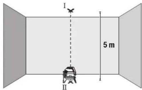
- Mark the centre of the top laser point on the ceiling (point I). Also mark the centre of the bottom laser point on the floor (point II).
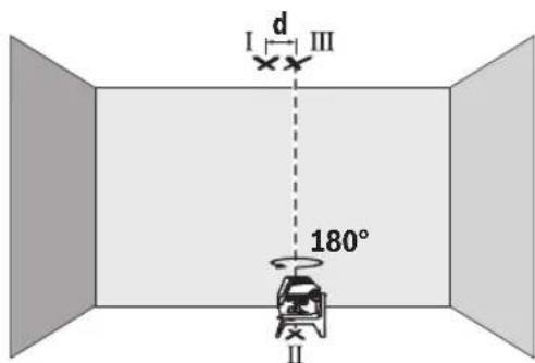
Turn the measuring tool by 180^ . Position it so that the centre of the bottom laser point falls onto the marked point II. Allow the measuring tool to level in. Mark the centre of the top laser point (point III).
- The discrepancy d between the two marked points I and III on the ceiling reveals the actual deviation of the measuring tool from the vertical plane.
You can calculate the maximum permitted deviation as follows:
Doubled distance between floor and ceiling × 0.7mm / m Example: At a floor-to-ceiling distance of 5m the maximum deviation amounts to
2× 5m× ± 0.7mm / m = ± 7mm .The points I and III must therefore be no further than 7mm from each other.
Working Advice
Only the centre of the laser point or laser line must be used for marking. The size of the laser point/the width of the laser line changes depending on the distance.
The measuring tool is equipped with a wireless interface. Local operating restrictions, e.g. in aeroplanes or hospitals, must be observed.
Working with the Laser Target Plate
The laser target plate (31) improves visibility of the laser beam in unfavourable conditions and at greater distances. The reflective surface of the laser target plate (31) improves visibility of the laser line. The transparent surface enables the laser line to be seen from behind the laser target plate.
Working with the Tripod (Accessory)
A tripod offers a stable, height-adjustable support surface for measuring. Place the measuring tool with the 1/4" tripod mount (18) on the thread of the tripod (32) or a conventional camera tripod. Tighten the measuring tool using the locking screw of the tripod.
Roughly align the tripod before switching on the measuring tool.
Securing with the universal holder (accessory) (see figure L)
Using the universal holder (26), you can secure the measuring tool on vertical surfaces, pipes or magnetizable materi
als, for example. The universal holder is also suitable for use as a floor stand and facilitates height adjustment of the measuring tool.
Roughly align the universal holder (26) before switching on the measuring tool.
Working with the laser receiver (accessory) (see figure L)
Use the laser receiver (29) to improve detection of the laser lines in adverse lighting conditions (bright environment, direct sunlight) and over greater distances. When working with the laser receiver, switch on receiver mode (see "Receiver Mode", page 25).
Laser Goggles (Accessory)
The laser goggles filter out ambient light. This makes the light of the laser appear brighter to the eye.
Do not use the laser goggles (accessory) as protective goggles. The laser goggles make the laser beam easier to see; they do not protect you against laser radiation.
Do not use the laser goggles (accessory) as sunglasses or while driving. The laser goggles do not provide full UV protection and impair your ability to see colours.
Example applications (see figures G-M)
Examples of possible applications for the measuring tool can be found on the graphics pages.
Maintenance and Service
Maintenance and Cleaning
Keep the measuring tool clean at all times.
Never immerse the measuring tool in water or other liquids. Wipe off any dirt using a damp, soft cloth. Do not use any detergents or solvents.
The areas around the outlet aperture of the laser in particular should be cleaned on a regular basis. Make sure to check for lint when doing this.
After-Sales Service and Application Service
Our after-sales service responds to your questions concerning maintenance and repair of your product as well as spare parts. You can find explosion drawings and information on spare parts at: www.bosch-pt.com
The Bosch product use advice team will be happy to help you with any questions about our products and their accessories.
In all correspondence and spare parts orders, please always include the 10-digit article number given on the nameplate of the product.
Malaysia
Robert Bosch Sdn. Bhd.(220975-V) PT/SMY
No.8A,Jalan 13/6
46200 Petaling Jaya
Selangor
Tel.: (03) 79663194
Toll-Free: 1800 880188
30 | Français
Fax: (03) 79583838
E-Mail: kiathoe.chong@my.bosch.com
www.bosch-pt.com.my
Great Britain
Robert Bosch Ltd. (B.S.C.)
P.O.Box 98
Broadwater Park
North Orbital Road
Denham Uxbridge
UB95HJ
At www.bosch-pt.co.uk you can order spare parts or arrange
the collection of a product in need of servicing or repair.
Tel. Service: (0344) 7360109
E-Mail: boschservicecentre@bosch.com
You can find further service addresses at:
www.bosch-pt.com/serviceaddresses
Transport
The recommended lithium-ion batteries are subject to legislation on the transport of dangerous goods. The user can transport the batteries by road without further requirements.
When shipping by third parties (e.g.: by air transport or forwarding agency), special requirements on packaging and labelling must be observed. For preparation of the item being shipped, consulting an expert for hazardous material is required.
Dispatch battery packs only when the housing is undamaged. Tape or mask off open contacts and pack up the battery in such a manner that it cannot move around in the packaging. Please also observe the possibility of more detailed national regulations.
Disposal

Measuring tools, rechargeable/non-rechargeable batteries, accessories and packaging should be sorted for environmental-friendly recycling.
Do not dispose of the measuring tools or battery packs/batteries with household waste.
Only for EU countries:
According to the Directive 2012/19/EU on waste electrical and electronic equipment and its transposition into national law, measuring tools that are no longer usable, and, according to the Directive 2006/66/EC, defective or drained batteries must be collected separately and disposed of in an environmentally correct manner.
If disposed incorrectly, waste electrical and electronic equipment may have harmful effects on the environment and human health, due to the potential presence of hazardous substances.
Only for United Kingdom:
According to Waste Electrical and Electronic Equipment Regulations 2013 (2013/3113) and the Waste Batteries and Accumulators Regulations 2009 (2009/890), measuring tools that are no longer usable must be collected separately and disposed of in an environmentally friendly manner.
Battery packs/batteries:
Li-ion:
Please observe the notes in the section on transport (see
"Transport", page 30).
Français
Download on the App Store

GET IT ON Google Play
Activation du Bluetooth®
Robert Bosch Morocco SARL
53, Rue Lieutenant Mahmoud Mohamed 20300 Casablanca
Tel.: +212 5 29 31 43 27
E-Mail: sav.outillage@ma.bosch.com
France
Robert Bosch (France) S.A.S.
www.bosch-pt.com/serviceaddresses
Transport
Calle Robert Bosch No. 405
C.P. 50071 Zona Industrial, Toluca - Estado de Mexico
Tel.: (52) 55 528430-62
Tel.: 8006271286
www.bosch-pt.com/serviceaddresses
Transporte
www.bosch-pt.com/serviceaddresses
Transporte
www.bosch-pt.com/serviceaddresses
Trasporto
www.bosch-pt.com/serviceaddresses
Vervoer
Download on the App Store

GET IT ON Google Play
Tilkobling af Bluetooth®
For at slà Bluetooth® til for fjernstyringen skal du trykke på Bluetooth®-tasten (10). Sørg for, at Bluetooth®-interfacet på din mobile enhed er aktiveret.
Frakobling of Bluetooth®
Bosch Service Center
Telegrafvej 3
2750 Ballerup
Pá www.bosch-pt.dkkan der online bestilles reservedele el
Tlf. Service Center: 44898855
Fax: 44898755
E-Mail: vaerktoej@dk.bosch.com
www.bosch-pt.com/serviceaddresses
Transport
Download on the App Store

GET IT ON Google Play
Aktivera Bluetooth®
For att aktivera Bluetooth® for fjarrystyrningen, tryck pa Bluetooth®-knappen (10). Se till att Bluetooth®-gransnittet ar aktiverat pa din mobila enhet.
Bosch Service Center
Telegrafvej 3
2750 Ballerup
Danmark
Tel.: (08) 7501820 (inom Sverige)
Fax: (011) 187691
Du hittar fler kontaktuppgifter till service har:
www.bosch-pt.com/serviceaddresses
Transport
Endast for EU-lander:
www.bosch-pt.com/serviceaddresses
Transport
www.bosch-pt.com/serviceaddresses
Kuljetus
Sigma npnon kal oepic
Euvtnpnon kalkaogapioooc
Na diatnpieTe to epyaleio meponnc navTa kaBap.
Mn ubioge to epyaleio meptonc o evpo n oe aaaa uypa. KaqapiTe tuxov punavon ^ eva uypo, paalako navi. Mn xpn- oponiHaete kaveva uypo kaqapaou n diaaUTN.
Na kaapite taiká idai terpa tic enipaveiec kovta otny édo toc aktivac letep kal va npoeexete va un dniouyouvta xoudelta.
EumptnneAatovkauouaecepapoyic
H unnpeta Eaunnpetnnc n eanaw anavta otic epwnaeic ao oxetka me tnv eniakeun kai tn ouvtipnoan tou npoiovtoc oac kaohc kai yia ta avtriatoxa avaalakrtika. xedia ouvapoo Aoyonnc kai naopopiec yia ta a vtaaakrtka 0a 8peite eni onk katw ano: www.bosch-pt.com
H ouda napoxic oumbouw tnc Bosch anavta euxapiatwc tic epwnoic oac yia npoivotma kac kai ta eapntmuata touc. Awote oe ole cie pewtoeic kai npayyalec avtaaaktikow onomega note to 10nphiio kwdiok apiog oupovae nvi vakida toun Tou npoiovtoc.
EAAaδa
Robert Bosch A.E.
Epxeiac 37
19400Kopwni-Athiva
Tnλ:2105701258
Φaξ:2105701283
Email: pt@gr.bosch.com
www.bosch.com
www.bosch-pt.gr
Iepatrepw dieuovoc eepic 8a pteire otyn aeKtpovik dieuvan:
www.bosch-pt.com/serviceaddresses
Meraqop
Ouviotmevec unatapie oivtwv Ailou unokevtai ot anaithoeicTwv emikivuvw ayaw. Ounatapie mnpovvaetapebpov obikcw an toxphnT xwipacllouoc opuc.
'Otav, 6muw, oI npatapiec anooteAovtai ano tpiouc (n.x. ae- ponopikwic n ie atia petaaetapopow) npenei va npouvtau diapopec ibiatrepec anaitnoeic yia tn oukeuaia kai tn anu van. E6w npenei, kata nTv npoeioaia tou teaylou anoToolhc va ztnthei onoohnote kai n ouubouh evoc eibkouy ienivduva ayaa
AnoTeAte TIC mntapiec movo otav to nepiBnma eivai ahtko. Kollate TIC ymuvc enapec me kollntk taivia kai va uokeuacete TIV mntapia kata tetoio tpono, wote autn va npu kouvieta ma onuakceuaia. Napakaolueva lauabave emianc unoyn oac kai tuyov nauonpc ec vkiec diataeic.
Anoupon

Ta opya metpno, oI enavaopnpzoevec
unatapiec/umatapiec, ta eapntmuata kai oU
okeuaie npenei va avakukawovtai pe Tpno
piiko noc to nepiaaov.
Mn pivvete Ta opyava metponnc kai tic mntapie csigmaikad anoppipmuata!
Movi yia xopec tnc EE:
UuWvA u TnV EupwnaiKn obnyia 2012/19/EE oxetikdae tic naiec nkeptikec kai nketpovikc ouokec kai tnetaopap Ta cnc obnyiac autnc oe bviKO bikaio ta axnpota opya va metponc kalouwva e Tnv EupwnaiKn obnyia 2006/66/ EOKoi xalauevec h npouonnonvec matapieic npenei va oulambdaoyovta Exawpiota, yia va avakukawoov u pto no fuiko npoc to nepiBaalov.
Se nepittwnon n evdeevmevc anouponc oI nektpkek kai nektpovike ouokeuec loyewdvexoeve npouiaic etikivbuvw ouiw mnpovv va exov eniBaie centtwoe cto nepiAALov kai otny avpwnyn ueia.
Enavaopotiopevec mnatapieC/MnatapieC:
Li-Ion:
PiopoeEe npapaKaIw TIC unoBeiEc otNv evotnTa Metapopa (Bene «Metaopap», Seiaiba 135).
Türkce
Güvenlik talimati

Tripod girisi 1/4" 1/4"
Enerji kaynagl
-Aku (Lityum iyon) 10,8V/12 V 10,8V/12 V
| - Piller (alkali mangan) | 4 × 1,5 V LR6 (AA) (pil adaptörü ile) | 4 × 1,5 V LR6 (AA) (pil adaptörü ile) |
| Isletim türlerine güre,isletim suresi(B)E) | Aküler/piller Aküler/piller | |
| - Çapraz çizgili ve noktasal mod | 18 sa/10 sa | 10 sa/4 sa |
| - Çapraz çizgi modu | 25 sa/16 sa | 13 sa/6 sa |
| - Çüzgisel,isletim | 35 sa/28 sa | 15 sa/12 sa |
| - Noktasal mod | 60 sa/32 sa | 60 sa/32 sa |
Bluetooth® olcum aleti
EPTA-Procedure 01:2014 uyarinca agirlk
www.bosch-pt.com/serviceaddresses
Nakliye
Robert Bosch Sp. z o.o.
www.bosch-pt.com/serviceaddresses
Transport
Trvale svfti zlute 75-35%
Bliká Červěne < 35%
Nesviti - Vadny akumulator
-Vybite baterie
S vybijenim akumulatoru, resp. bateri se pomalu snizuje jas laserovych car.
Download on the App Store

GET IT ON Google Play
Zapnuti Bluetooth®
Bosch Service Center PT
K Vapence 1621/16
692 01 Mikulov
Na www.bosch-pt.cz si si muzete objednat opravu Vaseho stroje nebo nahradni dily online.
www.bosch-pt.com/serviceaddresses
Preprava
Dopurocené lithium-iontove akumulatory podlehaji pozadavkum zakona o nebezpechnych nkladech. Tyto akumulatory mohou byt bez dal'sich podminek prepravovany uzivatelem po silnici.
www.bosch-pt.com/serviceaddresses
Transport
www.bosch-pt.com/serviceaddresses
Szallitas
IaTn3rOToBnEHHyKa3HaHaNocJeHHeCTpaHnCe 0bIOKKnPyKOBoDCTBaHnHaKOpNyce HdEIN.
KoTakTha HhOpMaun OTHocHtBHo HmnpTepa coepKHTcHa ynaKOBKe.
Cpok cny6bln3denn
Cpok Cnyk6bln3dennncocctabnre7 net. He pekomehyertcK 3Kcnnyataunno ncteueHHN 5net xpaehnnc DaTbH3ROTOBHeHH6e3 npedapntelbHO npOBepKn (DaTy H3ROTOBHeHH cM. Ha 3TNKeTke).
IpeueHb KpHTHueckHX OTKa3OB H OWH6OHyB IeJCTBnI NepcoHaHa HN NpIb3oBaTeJIa
-HeHcN0lb3OBaTb npnIOBbIeHNn DbIMa HEnOcpeCTBeHHO N3 Kopnyca N3dennr
-HeHCIOB3OBaTbHaOTKpbITOMnpoCTpaHCTBEBOBPMA DOXDA(BpaCnblAEMOBoE)
-He BkIIOuATb npn noJaHmN BoDb I KOpNyC
Kpntepnn npedeBbix coctoHHN
- noBpeKdEn KOpNc nAeJIINr
TnHn nepnoaHocb texHueckoro 6cnyXBaHHN
PekomeHcyTcOHTbHHCTpyMeHrOT Nblnn NoCne KaK-DOHOHCNOB3OBAHN.
Xpahenne
Heo6xOIMO XpaHb BCyXOMecTe
Heo6xoJMO XpaHHTB DAnHOTNCTOuHKNOB NObblIeH HbIX TEMNEpApTy HBO3JeCTBnCOnHehBix Lyuei
- npn xpaHenn Heo6xOIMO n36eraTb pe3Koro nepenada TeMneparyp
-ecnHhctpyMeHT NoCTaBnRETCB MmKoCymKe HnPiactIKOBOM KeiCe peKoMeHdyETcXpaHHTb HhCTpyMeHT B30J 3aunTHOH ynaKOBke
- noDpo6HbIe Tpe6oBaHN K yCNoBnM XpaHeHH CmOTpHTe B FOCT 15150-69 (YcNoBne 1)
TpaHcnpToPbObKa
KaTeRoPnueckn He DoNyckaetcnaJeHHe N IIObIe MExaHneckn BO3dEChTBHa Ha yNaKOBky npn TpaHCnpTINPOBKe
- npn pa3rpy3ke/norpy3ke He donyckaetcH nCnoIb30BaHne IIO6O BnDa TexNkH, pa6oTaIOeH no npHHuNy 3aKIMa ynaKOBKN
- noDpO6HbIe Tpe6oBaHnK yCIOBnM TpaHCnOpTIpOBKn CMOTPHTE B FOCT 15150-69 (YcIOBne 5)
Yka3aHnnoTexHnke6e3OnacHOCTn

IIOO6eueHn 6e0NaCHO HADExHOI pa6oTbI cN3MepHTenbHIM INHCtpymEtOM dONKbI 6bITb npouTHaHbIN C6bNOaTbcBc BCE NHCtpykUHHcNoNb3OBaHHe N3Mepu
TeNbHOro HNCTpyMeHTA He B COOTBETCTBnC hactOaMH yKa3aHHaMn YpeBaTO NobpeXeHem HNTERpHPOBaHNbIX 3aunTHbIX MEXaHH3MOB. HNKoRda He N3MeHnTe do Hey3HaBaEMocTH npeDynpeHnteNbHbIe Ta6nnKHa N3-MepNTeNbHom HNCTpyMeHTe. XOPOIo COXPAHNTE 3TN HNCTPYkUHN NPEPdABAHTE INX BMECTE C NPEPDA-ENH3MEPTeNbHOrO HNCTpyMeHTA.
OcToPOxHNo -npHMeHeHHe HHCtpymEntOB nIg 6cnyXHBaHHn HnIOCTHpOBKn HnN IpOueDyP Texo6cnXnBAHH, KpOme YKa3aHHbIX 3dEcB, MoKET npNBecTN K ONaCHOMY BO3dEhCTBnH H3nyeHH.
N3mepntenbHbHnHCTpyMeHT NoCTabnHETc C npedeynpeintenbHO TabnHcKOa3epHoro H3nyeHHa (noKa3aHa Ha cTpaHHe c H3o6paxeHHem N3mepntenbHoTo HHCTpyMeHTa).
Ecn TeKCT npdynpeHnteBhoT a6nueKn na3epHoro n3nyeHHe Ha BaWem poHOM 3bike, nepeD nepBbIM 3anyckom B 3KcnnyatauHIO 3akneIte ee HakneiKOHa BaWem poHOM 3bike,KOTOPA BxOaNT B06bem NOCTABKN.

He HanpaBnIte lyu na3epa Ha IIOeHnn KBNOTbIX HcAMH He CmOTpHTe Ha IpiMoH nn OTpaKaemblny na3epa.3TOT Lyu MoKet cIeNtB IIOe, CTb pNpuHoi HeCCACTHO CNYaH NIOBpeNTb Tna3a.
B cnyuae nonanaHnnaephoro nyuBa rna3 rna3a hyxHo HamepeHHo 3akpbItb HEmedneHHO OTBepHyTbca OTnya.
He MeHrTe Hnueero Bna3epHom yctpOcTBe.
He hcnb3yTe ouKn da pa6oTb c na3epHbIM HnCTpyMeHTOM (npHaadnHexHOCTb B KaueCTBE 3aunHbIX OOKOB. OKn dpa6oTb c na3epHbIM HnCTpyMeHTOM oecneuBaOT lyuwee pacno3HaBAnHe na3epHoro Lyua, Ho He 3aunuAot OT na3epHoro n3nyeHna.
He hcnb3yte ouKn npa6oTbI c na3epHbIM HnCTpymENTOM (npHaadNExKHOctb) B KaueCTBe coH- ce3aunTHbIX OOKOB HIN 3a pyem. OOKn dpa6oTbIC na3epom He oecneuBaOT 3aunTy OT YΦ-H3nyeHnI MEaAOT npaBnHbOmy CBETOBcPnATNO.
Pemont H3MePHTenbHOHcTpymenta pa3peaetc BblIOJIHTb TOnbKO KBAHnHpOBAHHOMy nepcoHany IToIbKO CHCNOB3OBAHmE OPHINAHbHbIX 3aNaCTeN.3TNM 06ecneuBaETc 6eONaCHOCTb H3MePHTenbHO HOHcTpymenta.
He no3BONHtte DeTAM NOb3OBaTbCnA3epHbIM H3-MepHTeNbHbIM NcHCTpymEtOM 6e3 npncMOTpa. JETMOrT IIO HeOCTOpOKHOCTN OCLeNTb Ce6nIIN NoctoPOHHX IIOJe.
He pa6oTaTe Cn3MePHTeNbHbIM HnCTpyMeHToM Bo B3pBBOONaCHO Cpe, No6nH3OcTH OT rOpOuHX XnKocTei, Ra3OB NblIN. B n3MePHTeNbHOM HnCTpyMeHTo MOryT o6pa30BaTbcNCKpbI, OT KOTOpbIX MoXET BOCnnaMeHHTbcNblN nn Napbl.
He BckpbBaTe aKKymyIaTOp. Pn3OM Bo3HnKaET ONaCHOCTb KOPOTKOr 3aMbKaHH.
Pn NOBpeKHeHH HeHaIeKaaem HcNoIb30BaHHn AKKymyIATOPa MoKet BbIeHITbcra3.AkkymyIATOP MoKet BO3rOpTaBCn HnB3pBaTbCn.ObecneYte npitOK CBExero Bo3dyxa n pRn BO3HKnHOBeHHxKAno6 o6paTHTecb K Bpaay. Ra3bl MOryT BblBaTb pa3npaKeHne DbixaTeHbHbIX nyTei.
Pn Hn HnpaBnHOM nCnONb3OBaHNn 3aKKymyIaTopa MoKet noteYb KnKOcTB. N36eAraTe cOpNKoCHOBeHH C Hei. Pn CnyaHOM KOtAKte IpomOIte COOT-BETCTByIOUee MeTO BOIOE. EcIN 3TA KnKOcTB NOna-ET B rna3a, TO dONONHIneBHO o6paTHecb 3a NOMOsbIO K bpaCy. BbITEKaIOsA aKKymyIaTOPHaJ KNDKOCTb MOKet pNBeCTn K pa3dpaKeHHO KOKn Hn K OKO-tam.
OctpbIMn npedMetamn, kak Hanp., rB03dEm HnH OTBePTKo, a TaKxE BHeWHM CNIOBbIM BO3dNCTBHeM
MOXHO NOBpeHb akymyIaTOPHyO 6aTapeo.3To MOKET PnHBecrN K BHYTpHeHemy KOpOTKOMy 3aMbIkaHHIO, BO3RopaHIO C 3aDblmneHem, B3pBy NII NepePReby aKymyIaTOPHo 6aTapen.
3aunuane HeHcnonb3yeMbI aKKyMnTOp OT KaHcEApCKNX cKpenOK,MOHET,KNIOe,ΓBO3Je,BHNTOB HApYHX MaNEhBKnX MetaIINueCkNx PpeMeTOB,KOTOpbIE MoRyT 3aKopoTHTb NIOOca.KoPOTKe 3aMbIKAHHe NIOIOCOB aKKyMnTOpa MOKeT pINBecTH K OKO-ram HIN NOxapy.
McnoIb3yIte aKKymnIaTOpy6aTapeIO ToNbKO B H3- dHnx H3rotOBHTeIN. TOnkO TaK aKKymnIaTOp 3aun- uenOT onaCHO npeperpy3kn.
3apKaIte aKkyMnyTOpHbIe 6atapen ToIbKO c NoMoUcBIO 3apAHy xCTPOCB, peKOMHeOBAHHbIX H3rTOBHTeMe. 3apAHOe yCTPOCBTO, ppeyCMTopeHHoe DnONPeJeENHO BnDA aKKMyNtOpOB, MOXET PnBECTN K NOxApHOI ONaCHOCTN pIN NCIOJIb3OBAHN erO C DpyrHMn aKKMyJITopAMH.

3aunuateakymnyto6ataeioOT BbICOKX TEMnepaTp, Hap., OT dntenbHO rHOHARpeBaHHa COHue,OT ORH, rR3N, BOblnBnH.CyueCTByeTOnaCHOCTb B3pBaH KOPOTKOrO 3aMbKAHH.

He yctanabnbaTe N3MepeHtBbIy HNCTpyMeHT MArHHTbIe PpHnAdnEeXHOCTb B6nn3HmNpHaTbTO HPOuHX MeHcHckx annapaTOB, HAp., KAPNoCTMMyrTopoB HHCynHoBbIX HaCOCOB. MarHtB I3-MepHTeBHO INcTpyMeHTa N pPiHaIeXHOCTH CO3dAOT NOE, KOToPOe MOKeT OTPuaTeBHO BnHraTB Ha paBoTy HmPnHaTbTOH MeMNCHKnx aannapaTOB.
ДерхиTe H3МePHTeBbHbI HNCTpyMeHT N MaHHTHbIe npHaJdIeXHocTH BdaIHNOT MaHHTbIX HOcHTeIe DaHHbIX N OT pN6OpOB, YyBCTBHTeBbHbIX K MaHHTHO My nonIO.Bo3JeCTBHe MArHToB H3MepHTeBbHO rHCTpyMeHTa I npHaJdIeXHocTe MOKeT pNBeCTn K Heo6paTMoN NOpe DaHHbIX.
PepedIIO6bIMMaHmnyIaIcHmMCn3MePeITenbHBMHCtpyMeHTOM(HaNP.,MOHTax,pa0bTI NO Texo6cyJXHBAHIO Hnp.),aTAKKe npN TpAHCnOpTHPOBKe XpaHeHH BbIHMaTe AKKMyIaTOP H3NeKTpOHCTpyMeHTa.PnHnpeHAmpeHHOM pInBeHHN BDeICTBNE BbIKNoTaIeI BO3HkaET OaCHOCTbTPaBMPOBaHNA.
Octopoxho!Pn HcIOnb3OBaHN H3MepeHTeBHO HNCTpymEnTa C Bluetooth®BO3MOXHbI NOMEXdIpyrHx npH6OpOB HycTaHOBOK, CaMonetOB H MeHNuHNckHX annapaTOB (Hanp., KApDIOCTMMyTApTOB, CnyXOBbIX annapaTOB).KpOme TOrO, Heh3ra NOnHOCTbIO HCKNIQUHTb HaHeceHHe BpeDA HxOJaUHMcB HENOCpeCTBeHHo 6IN3OCTNIOJIM HxHBOTbIM. He nONb3yTeCb H3MepeTEnbHbIM HNCTpymEtonC Bluetooth®B6IN3H MeHNCHckHX annapaTOB, 3anpaBOUYbIX cTAHCIN, XMHueckNX yCTaHOBOK N TeppToPn,HaKOTpbIX cyueCTByET OAnCHOCTb B3pbIBa HN
MOryT NpOBoNDtbcB3pbIBHbIe pa60bI. He NoJIb3yTeCb H3MePHTeHBbIM HcHcTpMeHToM c Bluetooth BcAMoTeaX. CtapAteCb He BKIOUaTb erO Ha npOdoJKNHTenbHOe BpEMB HenocpeCTBeHHoB 6nN3OCTn OTena.
CNoBechTobApHb3nak Bluetooth® n rpaΦnueckn 3nak (nOrToH) ABnIOTc 3apErHCTpnpoBaHHbIM TobapHbIM 3nakOM cO6CTBeHHocTeblu BoTeoth SLG, Inc. KomnHaRa Robert Bosch Power Tools GmbH nncnbsyET 3TO CNoBechTobApHb3nak/NOrToHn no nHcnEHNH.
Onncahne npoodykta u ycnyr
Ponanycta,co6IoudaItennIOCTpaunB Hauane pykoBODCTBa no kcnnyataun.
PpMHeHnNoHa3NaeHHIO
I3mepnteBbHINHCTpyMeHTnpedHa3HaueHnIOnpeDeneHnIIPOBepKnTopn3OHTbHbIXNBePTnKaJIbHbIXNIHNIOTBECOB.
H3mePHTeBbHnHcTpymEt pnproEnIpa60bByHytpnOMeueHnHaOTKpbTOM Bo3dyXe.
Pn nOmouN NOBOPoTHOro KpennenHrM 2 H3MepeTeNb HbHnHCTpyMeHT MoKHO NOBOpaHbTaH 360° BOKpyr cHtPaIbHo, NoCToHHO BnHMOn OCN OTBeCa. 3To No3BOJReT TOHcHaCTPOHTb Na3epHbIe IINHn, He H3MeHeHra NIOXKeHn H3MepeTeNbHO IHCTpyMeHTa.
H306paXeHHbIe coCTaBHbIe qACTn
HymepaunipnectabnEHbixcoCTabhixyacteBbINOHeHa noN3oPaxKeHHIO N3MepHTenbHO IHCTpyMeHTa Ha cTpaHHue C HIOCTpauNM.
(1) HappaBnaIounn na3
(2) BbikniouyateNB
(3)OTBepCTneIyBaBixOda na3ePHoro nyu4
(4) CootonHe 3apda akKymnTopa/6atapeek
(5)ИнданаторфкаторmaRTHnka
(6)KhoIIpaepKIma pa60Tb c pIneMHNKOM
(7)Инданатор рекима pa60тб спнemнkom
(8) Khoinka BbIbopapeKMa pa60Tb na3epa
(9)ИндикатOP coeДиненЯ Bluetooth
(10) KhoNka Bluetooth
(11) AKKMyJITOpHbIOTcK
(12) AKKMynTOp
(13)Koxyex nepexoDnka dna 6aTaapeek
(14)Батарениa)
(15) KhoIka pa36IoknOBk nAkkymyIaTopa/nepexoHnK dIg 6Taapeek
(16) Kpbiuka nepexoDnka dna 6aapeeKa
(17) Ppeynpeintenbna Ta6nueKa Ia3epHoro n3ny-ueHHA
(18) ένελησινιδινιατινιβειν 1/4"
(19) CepHbH HOMep
(20) Haprabnouza peka
(21)MaHHT
(22) IpoDIOIROBaTOe KpenEJHoe OTBepCTHe
(23)Поворот Shoeкpenпенhoea
(24) BnHT TOHOn peryInpOBKn NOBOPoTHOrO KpenneHHa
(25)ПOTOnOuHанСкобa
(26) yHnBepcaIbHoe KpeIeHHe
(27)Поворотая патфогмa
(28) NylbT nIcTaHnOHHoro ynpaBneHnra
(29) Naapehby npneMHNKa1
(30) Oukn dna pa6oTbI cna3epHbIM HHTpyMeHTOMa
(31) BnHpaMapka dIy naePHoro lyua
(32) LJItaTHNb
(33) Teneckonnueckn wecet
(34) 3aunthbnyuchexon
(35)пекхонддбатаeek
(36) ymnp^i
a)H3o6paXeHHbIe HnONnCAHHbIe npHnADJeKHOCTHe BXOJrB CTAnDAPThbIO bSeM NOCTABKn. NOnHbI accOPTmEHT pHnADJeKHOCTe BbHaJaTe BHaWei npPorpMaMe npHnADJeKHOCTe.
Texnueckne daHbIe
HHTAHHe H3MePHTeBbHOrO HcHCTpyMeHtA
H3mepnteBbHnHCTpyMeHT MoKET pa6oTaTb O6bUHbIX 6atapeek HnO TnTHeBO-HOHHO AKKyMnyTopHO 6atapen Bosch.
3Kcnnyataaunr oAkkymyIaTopno6aTapeH
Ponb3yntecb tonbko 3apnHbIMn yctpoCTBaMn, yka3aHHbIMN BTEXHuecKnx npaMetpax. TOnbko 3TN 3apRnHbIe yctpoCTBa pnpoNDbl nIINHeBO-NOHOrO aKkymnapota Baawero n3MepeTbHorO nHCTpyMeHTa.
Yka3aHHe: PnmeHeHne aKKyMnyIaTOPOB, He npEHa3Ha-ueHHbIX nlaDaHHOro N3MePHTeNbHO INCTpyMeHTa, MOKET npBeCTN K c60aRm B pa6Ote Hn NobpeKeDeHHo N3MePHTeNbHO INCTpyMeHTa.
Yka3aHHe: AkkMyIaTOpHa 6aTape nocTabnEeTcB aCTNHO 3apAKeHHOM COCTOHH. Iy oecneehn NOHOM MOUHOCTH AKKMyIaTopa 3apAInTe erO nonHOctbIO nepei nepBBIM pImMeHHeHem.
HINHNOHHbAkkymyIaTOpMOKTe6bITb3apJKeH BIO6oeBpem6e3cokpaueHnCpOaCnyk6bl.PpeKpaueHne npoCecca3apJKnHeHaHOCTBpeaAkkymyIaTOpY.
IITnEBo-HoHHa AkkymyIaTOPHa 6batape 3aunuSha oT rny6koK pa3paJKn CnCTeMo, Electronic Cell Protection (ECP)".Pnp pa3paJKeHHOAkkymyIaTOPHo 6bataee H3Me-pntbHbHmHcTpMyeH BbIKIOaETcB 6laorapx Cxeme 3a-
He BkIouaTe NOBtOPO H3MePHTeNbHbHnHCTpyMeHT NocLe Eero OTKIOUeyHn PnH NOMOu CXEmbl 3a-NTb. AKKyMylTOp MOKeT 6bItb NobpeXdH.
IyctahOBKn 3apJxHnOTo AKKMyTnTopa (12) BCTaBbTe ero BAKKMyTnTOPbIOTcK (11) TaK,TO6bl OH OTcETnBO BOWeI B3aenHeH.
ДлгИЗВЕЧЕНаakKуМЛТОпа(12)HAKMITEHa KHOПК pa36LOKINPOBKN(15)иИЗВLEКITEaKKyMЛТОн aKKyMЛТOPHOROOTCEKA(11)He npIMeHЯTe npH aTOM cHnbl.
3KcIyataaOn 6Taapeek
B INMepHTeHbOM HNCTpyMeHTe peKoMeHdyETcR hCNoIb30BaTb IeNoOHO-MapraHueBbe 6atapeKn.
Pa6oTa cABTOMaTHueckHM HHBENHPOBaHHem (cm.pnc.B-E)
YCTaHOBIne N3MepIneIbHbI INHCTpyMeHT Ha CTaBnIbHoE rO pIN3OHTaIbHOe OCHOBaHne INN 3aKpeInTe erO Ha NOBOpOT-HOM KpeInHeHH (23).
IpaobtcbaTOMATHueckn HNBENPOBaHMe nepeBHBte BbIKIOaTeNb (2)B NOJIOKeHHe «
Функця abTomatueckoro HnBENPobAHN KOMneHCpyET HEPOBHOCIN B paMKaxДиana3OHa aTOMaTHueCKORo HNBENPobAHN B ±4°.ИМepHTeBbHbI NcHcTpMeHT HNBENPobAH, KAK TOIbKO Ia3epHbIe LyuN pKePaTIN MmTaTb.
EcHn ABToMaTHueeCKoe HHBENHOBaHHe HeBO3MOxHo, HanpHMeP, T.K. NOBepXHOCTb, Ha KOTOPo YcTAHOBJIeH N3MePHTeIbHbN IHCTpyMeH, OTNIuAeTcO TROP3OHTaIIb 60Jee yem Ha 4^ , na3epHbIe Iyun MIRaKOT B6bICTpOM TEMne.
B Takom cnyae yctaHObHTe N3MepTeNbHbN INHCTpyMeHT roN3OHTaJIbHo N IOXdNTecb OOKHaHnA BTOMaTNUeCKOrO caMOHNBeHNPoBaHn. Iocne TOrO, KaK N3MepTeNbHbN
HNCPTyMENT BOIeT B Dnana30H ABTOMaTHueCKTO HNBENPOBaHH ± 4^ ,Na3epHbIe LyuHaHaiOT HeNpepbIBHO CBeTNTbC.
PnCOTpceHnIXnH3MeHeHHX NOLOKeHHN BO BpeMpa60bI H3MePHTeBHy INHCTpyMeHATBtOMaTHueckn CaMOHNBeHInPyETc. Nocne HNBEnPiPOBaHHN POBepbTe NOLOKeHNE Na3epHBx IyueN IO OTHoWeHHIO K peNepHBIM TOUkAM, 4TO6bI H36EkaTb OwH6OK Bpe3yNbTaTe CMeUeHHN H3MePeTbeHOrO HnCTpyMeHtA.
Pa6Ota c φнкcatopom MaTHnka (cm. pnc.F)
Ipaobtbc6bokpOBKO MaTHNka nepeDbHbTe BbIKNoUoateBb2BnOJKeHne(On).HINKAtOp 5bOKPOBKNMaTHNka(5)ropHT KpaChbIM Hna3epHbIe IHHHHeIpepbIBHO MraOT B MeDJIeHHOM TEMne.
Pn pa6oTe C 6IOKIOBKO MAHTHnKa ABTOMaTneCKoe HNBeHIpOBaHHe BbIKHOeHO.3MepeNTbHbI INHCtpyMeHTMOXHOepKaTb Ha Becy Bpyke HIN NOCTaBHTb Ha HAKNHOEOcHOBaHHe.Pn 3OM Na3epHbIe LyuH 6OJIbWe HeHNBEHNPYOTcH He O83aTeBHo 06pa3yIOT nepNeHNkyJIrp.
Ductauohoe npablenno Bluetooth
N3mepntbHbHnHCTpyMeHT OcHaueH MoyIeM
Bluetooth, KOTOpBn PnP NOMOuPi PAHOTeXHNUeCKHX
CpeCTB oEocneUHBeT B03MOxHOCtB nCTaHNoHHO
ynpaBHeHra uepe3 cMaprO h CInTEppeHcOM Bluetooth.
HfopMaunO Heo6XoHMbIX CnCTeMHbIX Tpe6oBaHNx DnA
coeHHeHra Bluetooth HaxoNTca Ha caTe Bosch no aDpecy www.bosch-pt.com.
PnDuctaHOnHOMynpAbeHHNoBleoth BO3MOKHa 3aepkKa NO BpeMeHN MExdy MObIbHbIM OKOHeuHbIM yCTPOiCTBOM N3MEPeHTeHBbIM INHCTpyMeHToM BCNECTBne IIOXIN YCNOBCHB3N.
IInCTaHNoHHoe ynpaBnEHeN OocTynHO B npnIOKeHNX Bosch. B 3aBNCUMOCTOn OT yCTpoNCTBaNX MOKHO cKaaTaB B COOTBETCTByoUx MAra3Hax:

Download on the
App Store

GETITON
Google Play
BkJIOueHne Bluetooth®
YTO6bI BKNIOHTB Bluetooth®nIaNCTaHcHONHO ynpaBneHnHAKMTe KNONKY Bluetooth®(10).YIOCTOBepbTeCb, YTO INTEPpeicn Bluetooth®BKNIOueH Ha OKOHeHOM MOHbHOM yCTpOICTBe.
Iocne 3anycka npniloxkeHn Bosch yctaHaBnBaetc Cb3b MExdy MoNBbIM OKOHeuHbIM ycTpoiCTBOM H3MepeHTeNbHbIM IHCTpyMeHtOM. Pnp O6hApyKeHH HeCKoJIbKx AKTNBbIX N3MePHTeNbHbIX IHCTpyMeHToB BbIepeTne NOxOJrN H3MepeNTeNbHbIN IHCTpyMeHt. Pnp O6hApyKeHH ToJbKO JInMb ODHO RkTHBHO rN3MepeTbeHOrO IHCTpyMeHtCoEINHeHHe YcTaHaBnBaETc ABTomAtueckn.
CoeHHeHne yCTaHOBNeHo, KOrDa 3arOpaeTcR HnDnKaTOp Bluetooth®(9).
CoeHHeHnNo BluTooth MoKTeI npepBaTcBn H3-3a 60nbUoro paacToHHN Hnn npenATCTBm MExdy N3MepnTEbHbIM INCTpyMeHTOM NMOHBHbIM OKOHeuHbIM yCTpoiCTBOM,aTaKKe H3-3a 3NeKTPomarHHTbIX NOMex.B TaKOM cnYue HnDkaTop Bluetooth (9) MURAET.
BbIKHoueHne Bluetooth®
IINBbIKHOUeHHnBluToothDnIINCTaHUNHOHOROynpaBHeNHAHXMITEKNKNYBluTooth(10)NNBbIKHQUHTN3MePNTeHBnIHCTpyMeHT.
KoHTpOJIb TOnHOCTn H3MePHTeIbHOrO HHCTpyMEnTa
ΦaKToBb, BnHIOUe Ha ToOHcTb
HanboBuee BnHHe Ha ToUHcTb Oka3bIaBt OKpyKaIOua TemepaTypa.BoObeHHocTH TempeaTpHbIe nepenabI, HMeoune MeTo NO Mepe ydaHnro OT NoBbl, MOryT CtaTb npuHNO TkloHeHna3epHoro lyya.
NocKoIbky npenapTeMnepaTpby Han6Oone OuyTM B6HIN3n rpyHTa,To Ha yAcTkax DHHHO CbbIe 20 M n3MePntBHBn HnCTpymET CneIyET YcTaHaBnBaTb Ha WtATNB. KpomeTOrO,ycTaHaBnBaTBe N3MePntEhBn HnCTpymET,NO B03MOxHOCTH, BcepeInHe pa6oey nnoaadn.
Hapy C BHeuHMn BO3eJCTBnMn, CneuHueckne nI INHCTpymeHa BO3eJcTBn (Hanp., naDeHnN mCnHbHie yApbl) taKke MOrY T npBODHTb K OKNOHEHnM. POToMyc BCerda nepeed Haaylom paOto pnoBeprTe ToUHOCT HnBeLipOBaHn.
PpOBepaIe Chauana ToUHOCb IIO Bblcote N ToUHOCTb HnBENIOPOBaHnro pOn3oHTaJIbHOJ Na3epHOJ LInHH, a 3aTeM TOOHOCTb HnBEIpNOBaHnB BePTKakHoJ Na3epHOJ LInHHN IN TOOHOCb paCNoIooKeHH TOuek OTBeca.
EcnB BO Bpemr OJHOH 3 npOBepOK H3MpeHTenbHbI INHCTpyMeHT pEBICHT MaKcHMaJIbHO DOyCTmOe OTKIOHeHne,OTaIte ero B peMOHT B cepBnCHyo MaCTepckyHO Bosch.
PpOBepKa ToUHcTn Rop3oHTaIbHOIN HNNH NO BbICote
JIa KOHTPOH Heo6xOIM CBO6OHNbI OTpe3OK 5 MHa npouHOMrpyHTe MeKdyCTeHAMN B.
-3aKpeHnTE H3MepNTeBbHbHnHCTpyMeHT B6nH3n CTehbA Ha 1tATnBE nnn yctAHOBnTe erO ha npouHoe, nIOCKoe OCHOBaHHe. BkHOnTe H3MepNTeBbHbHnHCTpyMeHT. Bbi-6epHTe pexHM nepeKpecTHbIX nHHn C aBTOMaTHueckm HNBenHOBaHem.
- HanpaBbTe Na3ep Ha 6nHexIO CTeHy A n daTte N3mepTeNbHOMy HNCTpyMeHTy HNBEnHPOBaTbcra. OTMeTbe CepeHNy TOcKN, B KOTopoJ Na3epHbIe NHHN NepeceKaIcra HA cTHe (TOka I).
-ПовернITE ИЗМерптельнИнСТРУМЕТ Ha 180°, поддпerte, пOKA ON He npOn3BeTeCaMOHBeNIpOBAHHe, nOTMeTbTe ToUky nepeKpeUBaHnI Na3epHbIX NHHnHa npOTIBONOLOXHOr cTeHe B (ToUka II).
- YctaHOBnTe I3MepnteIbHbI INCTpyMeNT - He NOBOPaHBAero-B6n3N CTehBi B, BKIOHTe ern daTe emyBpem HNBENPOBaTBCa.
-HactpoTe H3MePHTeBbHb HnCTpyMeHt NO BbICote (C noMoIbHO WtTaHbA HIN NODKlaDOK) TAK, YTO6bI TOUka nepeKpeuBaHn Ia3epHyX INHn ToHcOBoN a paHee OTMeueHHo ToKoII Ha CTHe B.
-ПовернITE ИзмерпгельнIHCTpymERT Ha 180°, He Из-MeHRЯ BBICOTbl. HanpaBte INHCTpymERT Ha CTehY A taK, UTO6bl BEpTKaJIbHAR na3epHAR liHHI npOXOJla uepe3уKe OTMeueHHyTOUky I. NOOxDNTE, NOKA INHCTpymERT He 3aKOHHT cMOHINBENIOBaHHe, HOTMeTbTe TOUYKe nepeKpeuBAHnI na3epHbIX liHHI Ha CTehE A (touKa III).
-PacctoHHeMeKyDByMnO603HaueHHbIMNTOUKaMnI I1 HA CTeHe AOTpKaaeTΦaKTNuEeCKoe OTKIOHeHHe H3MePHTeBHOHOHCTpyMeHTA NO BICOTE.
Ha yactke 2 × 5 M = 10 M MaKcHMaJIbHO DOIpyCTHMoe OT-KIOHEHHe COCTABHET:
10Mx±0,3MM/M=±3MM.TaKHM o6pa3OM,pacCToHnede MEXMyTOUkAMN I H III He DoJNHO npeBbIaTb MaKc.3MM.
PpOBepKa TOnHOCTN HNBENHPOBaHHaTPOH3OHTaBHOH NHHH
I npOBepKn Tpe6yeTc CBO6OHa nOBepxHocTb npn6n. 5×5M.
-MoHTnpyTe H3MePHTeBbHbHnHCTpMyENT nocepeHHe MeJy CTehAMN A N B Ha WtATMbE HnYcTaHOBHTeeroHa npOuHoe,POBHOE OCHOBaHHe.BbIePte Trop3OHTaB- HbI NInHeHbI pExHM C aBTOMaTHueCKM HnBeINpOBAHnEM HdaTe H3MePHTeBbHOMy HnCTpMyEHTy CaMOHNBe- IInPOBaTbCra.
-06o3HaBte Ha paccToHHn 2,5 Mo H3MePHTeHbHorO HcTpyMeHTa cepeHNy Ia3epHOrO LyuHa Ho6ExxCTeHax (TOUka I Ha CTHe A N TOUka II Ha CTHe B).
- YCTAHOBHTe NOBEPHyTbI Ha 180° H3MePHTeHbHbI HHCTpyMeHT Ha paCCToaHHN 5 M DaHTe eMy caMOHBeJIINPOBaTcR.
- BbipOBHnTe H3MePHTBHyI HnCTpyMeHNT NO BbICote TaKMM O6pa3OM (c NMOU bIO UaTbNA HIN NODIOXHB UTOH6yNb No Hero), UTObI CEHTp Na3epHOIN NHHN TOHNO nonadan Ha npEBAptelbHO 0o3HaueHHyHO HA CTHe BTOky II.
-0603HaBte Ha CteHe A CepeHHy Na3epHNo IINHn B KaueCTBe TOUKn III (BepTKaIbHO HAD INN NOI TOUKOI).
-PacctoHHeMeKJyDByMnO603HaueHHbIMTOUKAMN I III Ha CTeHE AOTpKaAeTpaKTHueCKe OTKIOHeHne N3MePHTeBHO HCHTpymEHTaON.
Ha yuaCTke 2×5M=10MMaKcHMaJIbHO DoIpyCTHMoe OT-KIOHeHHe COCTaBnAET:
10M×±0,3MM/M=±3MM.TaKHM o6pa3OM,pacCToHHe d Mekdy TOUKAMN I H III He DoJNHO npeBbIaTb MaKc.3MM.
PpOBepKa TOpHocTH HNBENHpOBaHn BEPTKkAIBHOIHHH
Длп поевки Bam Tpe6byTe rpoem Dbeprn,В obe CTopoны OT KOTOPORO (Ha npouHOM nony) ectb Cbo6oHoe npocCTpaHCTBOДПИHON He MeHee 2,5M.
- YctahOBNTe H3mepHTenbHbI HnCTpyMeHT Ha paccTcHIN 2,5 MOT DBepHO rpoema Ha npouHoe, POBHeO cHOBaHne (He Ha WtTaHB). Bb6peTe BePTKAbHbI NInHeHbI peKIM C ABTOMaTueCKM HnBeNIpOBAHem. HanpaBBTe Na3epHyIO IHHIO Ha DBepHOI npoEM n daTe H3mepHTenbHOMy IHCTpyMeHTy CaOHNBENpOBAtCB.

-OTMeTbTe CepeHnBy BepTKaJIbHOI HINHn Ha nOyB npoeMe DBePN (TOkaI),Ha pacCToHnB 5 M cDpyroI CTOpOHbl npoeMa DBePN (TOkaII),a TaKKe no BepXHEmy KpaIO npoeMa DBePN (TOka III).
-Повернite Измерпелбий Иструмент ha 180°и noCTaBbte erо NOДугю CTOPOHу DBePHORO npoema nprmoNo3aHToUKNII.DaHTe H3MepHTeNBOMpynp6OpCaMoHNBeHnPoBaTcHnHaHpaBbTe erO BePTHKaJIbHbIe Na3eHbIe lyuHtak, uTObIx IcepeDnHbI npoxOdIN ToUHOpe3ToUKNII.
-Пометътсеренинулазерноуна Вьрхим КрадоверноюpoemaΚakToчkyIV.
-PacctoHHe dMeKdyDByMRAO63HaueHHbIMTOUKAMN III IVOTOBpaKaetΦaKTHeCKOEOTKNHOHeNE H3MEpHTeB-HORIOHCTpyMeHTAOTBepTKaH.
-ImepbTe BlicOTy npoemaDbepn. MaKcHMaNbHO dOpyCTHMoe OTKIOHeHHe paccuTbIbAeTCr cJeDyUOM 6pa30m:
BBOHnBa BbICoTa DBePHOrO NpoEma X,3MM/M
PiHmep: npN Bblcote DBePHOrO NpoEma B M MaKcHMaJIbHOEOTKIOHeHHe MOKeT CoCTaBnTb
2×2M×±0,3MM/M=±1,2MM.ToKn III IVdoJKNbHaXoDHTCBa npn 6OoHxN3MepeHHx Ha paCToHnMaKcHMy1,2 MM dpyr ot dpya.
PpOBepKa TOUHocTH OTBeca
ДлпnpobepknBam Tpe6yeTcra Cb6oDньи H3MepHtIbHbI yactOK Ha TBePdOM OCHOBAHn C paCCTOHRHeM OK.5 M MEKJy NOLOM H NOTOLKOM.
-MoHTpyIte H3MePTeIbHbI INHCTpyMeHt Ha NOBOPOTHOe KpennHe (23) n yctaHOBITE erO ha non. Bb6epTeTOueHbI peKIM I daIte H3MePTeIbHOMy INHCTpyMeHTYHBENIOPOBaTcR.
-06o3HaBte cepeHHy BepxHe Na3epHOI TOKn Ha nOToJIke (TOyKa I). O6o3HaBte TaKxce cepeHHy HIXHe Na3epHOI TOKn HA NOy (TOyKa II).

-ПовернITE ИЗмерпелбий ИСТуремпт ha 180°.Ранолкпге ergTak,чTOБиCEpeДИнHa HIXHKeI Na3ePFOH TOUKN HaxOДиNacbВ paHee OTmeuHHOH ToUke II.ДaHTeИЗМерпельHOMY INCHTpymeHTy HINBeIInPoBaTbCЯ.OTMeTbTecepeDHy BepXHeI Na3ePFOH TOUKN (TOUka III).
-PacctoHHeMeJyDByMRO6O3HaueHHbIMTOUkAMINIIIHaNtOToJIkeOTOppaKaetΦaKTHueCKOEOTKIOHeHHeH3-MepntelbHOHOHCTpyMeHTAOTBepTkaHn.
MaKcHMaJIbHO DoIpyCTHMoe OTKIOHeHne paCCHTbIBaETcR cIeNyUOIM 6pa3OM:
ДовиhoepacSTOnHMeJyNOMHNOTOKMx0,7MM/Мпгмер:прпacSTOnHmMeJyNOMHNOTOKM5MMAKCMaNbHOeOTKJOHeHHeMOXET COCTaBnTb
2× 5M× ± 0,7MM /M = ± 7MM .TouKINIII DOnKHBi HaxoDnTBcPnO6OHXN3MepeHnxHa paCCToHmMaKCHMyM7 MMDPYOrDpyra.
Yka3aHnno npmHeHHIO
McnoB3yTe Bcerda TOnbKO cepeHny na3epHOH ToCKn Hnna3epHOHnnn DnOtMeTKn. Pa3Mep na3epHOH TOcKN/UnpHa Na3epHOH nnHH MeHReTcB 3aBNCMOCTN OT pACCToHNr.
V3MePHTeBbHbHnCTpMyeTobopyoBaHpaHOnHHTepeHcOM.Co6IIOaTe MeCtHbIe OPAHueHnNo pHMeHeHNO,HaP.,BCaMOteax Hn60bnHuaX.
Pa60Tb C BN3HpHO mApKoI
Bn3npna Mapka (31) ynyuetaet BnDnMoCTb na3epHOro ly-ya npn He6laRaonpnaTbIx ycNoBnx H ha 60nbux pacctoHnax.
OtpaKaIOUaI NOBepXHOCTb Bn3HPOH MapKn (31) ynyuwaet BuIMOCt bna3epHOI INHH, HApno3paHNOBepxHOCTN Ia3ePHyIO INHHIO TaKke BnDHO C TbINbHO CTOpOHb BN3HPOH MapKn.
Pa6oTa co 7aTHBOM (npuHaJIeXHocTb)
山taHB oecneuBaet cabnBHyO,peynpemyIO no BbCote onopy dIaH3mepeHH. NocTaBte H3meptenbHbIHNCTpymeHT H3DOM NOJ WtATNB 1/4" (18) Ha pe36by wTAHbA (32) INI O6bHORo FOToWtTbA. 3aFHKcpyTe H3-MepTeNbHbINHCTpymeHT C NOMOuB KpeNEXHOrO BNHTaWtTaHbA.
PepBapntbHo BbypOBHnTe 1tAtnB, npexde yem BKIO- qatb N3MePntbHbI HNCTpyMeHT.
ФИКСАЦСС NOMOДБУHNBEPCARbHOrO KpENNEHn(PnHnAaNEXKHOCTb)(cM.pHc.L)
C NOMOJIbU yHnBepcaJIbHOro KpeJIeHnra (26) MoJHO 3aKpeIITb N3MePHTeJIbHbI INHCTpyMEnT, HAp.. Ha BepTKaJIbHbIX NOBepXHOCTx, Tpy6ax HII HAmARHHuBAEmBX MaTePHaIax. YHnBepcaJIbHoe KpeJIeHne MOJHO TaKKe HcNoJIb30BaTb B KaueCTBe NoCDTaBKn. OHO o6JeerHaET BbIPaBHnBaHHe INHCTpyMEnTA IO Bbcote.
PpeBapnteBHO BbipoBnHTe yHBepcaNBHe KpeIeHne (26), npexKeYem BKIOuAtb NmepnteBhIn HNCTpymEHT.
Pa60a c napepbim nphemnKOM (npHnAdneXHoCTb) (cm.pnc.L)
Pnhe6naorponpnaTHOOCBeeHooCTn(CnIbHooeOCBeeHne,PnarnbleconHeuHbeNy)Ha6BoJIbOMpacCToRHMnDnnyUeHOhoxKDeHHa3epbHexNINHNNCIOB3yTeNa3epHybnPnemHk(29).PnpabotaxCna3epbHmPnEmHKOM BKNIOaHTpepeKMnPnemHka(cm.PekmPnEMHKa”,CTpaHua196).
OuKnIpa60TbIcna3epHbIM HhCTpyMeHTOM (npHaadNExKHOctb)
Naepehble OOK NTPOBBAHOT OKpykaHcBcET. NToMcyCBet Naepa KaKcTeC6Ooe npKm dIy3pHTbHo- ro BocnpnTn.
He hcnonb3yIe ouKn dIpa6oTbI c na3epHbIM HnCTpyMeHTOM (npHaadNexKHOCTb) B KaueCTBE 3aunTHbIX OOKOB. OKn dIpa6oTbI c na3epHbIM HnCTpyMeHToM oBecneuBaIOT lyuWee paCno3HaBaHne na3epHoro Lyua, Ho He 3aunIauIOT OT na3epHoro n3nyeHna.
He hcnb3yte ouk nla pa6tbcnaepbim HnctpymENTOM (pnhadneXHOCTb) B KaueCTBe cHn-3aunTHbIX OOKOB Hn 3a pyem. Oukn da pa6toBc naepom He oecneuBaOT 3aunTy ot YΦ-H3nyeHnN Meaakot PpaBnHOMy CBETOBOCPnTnIO.
PpHmepbI BO3MOxHBIX BnOBo pa6oTbI (cm.pnc.G-M)
PpIMepbBo3MOKHBx PpIMeHeHn H3MePteIbHoI OHCTpyMeHTa PpIBeDeHb Ha CTpaHuaxC pncyHaMn.
Texo6nyKbHaHne n cepBnC
Texo6cnyxHBaHne n ouhctka
CoepKeTe H3MepHtBbHbI NHCtpMeHT NOCTOARHO BnCTOTE.
HnKOrJa He NorpykaTe H3MepntbHbI HnCTpyMeHT B BOy HnDpyrHe KnKoCTn.
BbItpaIte 3aRpa3HeHmCyxO mKoTprnKo.He nCnonb3yTe KaKe-Im60 uNCTAue cpeCTBa Hn pactBopHTeH.
OuHuaIepeyIaepHOOC6eHHNOBepxHocTHYBbIXoHOROTBepCTHa3epaHcneItePn3TOM3aOTcyTCTBHeM BOPCINHOK.
CepBn KOncynbTHpObaHne no BOpocam npMHeHH
CepBnchbI OTenOTBeHT Ha Bce Baun Bonpocbl no peMOHTy IobcnyBaHnO BaWero npOdykta, a TaKKe No 3aNactrM. N3o6paKeHHc nPoCTpaHCTBeHHbIM pa3deneHHem DeNaTe HnHOpMauNo 3anactm MoXHO NOCMOTpeTb TAKKe no anpcy: www.bosch-pt.com
KoNneTnB cotpydHnKOB Bosch, npedocabnaIounn KOHCyNbTaunHa npedmET nCNOb3OBAHN pOdykUn, C yD0BObCTBnEM OTBETn HA Bce Baun BONpocbl OTHOCHTeB-HORo Hauen npodykUnn ee npnHaadJeXHOCTe.
Ioxanycta,Bo Bcex 3anpocax n 3aka3ax 3anactei 06ra3aTeIbHO yka3bBaIte 10-3HaHbI TOBapHbI HOpE np 3aBODcKoTabnueKe H3dJIeI.
IpynHnOHe 06cnyKbAHne H pEmOH 3eKTPOnHCTpyMeH Ta C6oJIIOEHNEM Tpe6OBaHH IN HOPM N3rTOBHTENI PNO IIN3BOJATCR Ha TeppHTOpHN BCex CTpaH TOIbKO BΦHPMeHHbIX IIN ABTOPN3OBaHHbIX CEPBCHbIX CEHTPAX «Po6epT BoW). IPEyIPEXJEHEH! NcNoIb3oBAHNE KOHTpaKaTHOH npOdyKUn OnACHO EKcIIyATAUIM, MOKeT pINBecTN K Uyepe6y IINBaWero 3dOpOBb. N3rTOBNeHne IN pacnpocTaPAHHe KOHTpaKaTHOH npOdyKUn npeCleJeYETC NO 3aKOH Y aMNHNCtpAHBHOM INYTOBHAM NOPAKe.
Pocchra
YonHOMOeHHa H3rOToBHTeMeOpraHn3aun: OOO «PObepT BoW» BaUyTHnCKoe Uocce, Bn. 24 141400, r. XmKn, MockoBcKa o6n. Ten.: +7800 1008007 E-Mail: info.powertools@ru.bosch.com www.bosch-pt.ru
DOnonHnTeNbHbIe apeca cepBnChbIX ceHTPOB Bbl HaidTeNo CcbInke:
www.bosch-pt.com/serviceaddresses
TpaHcnoptmpoBka
Ha peKoMeHdyeMbIe NITN-HOHHbIe AKKyMnyTOpHbIe 6batape npacPiocTpahnOTcTpe6oBaHnB OTOHOWeHN TpaHC
noptnpOBKn OAncbIx rpy3OB. AkkyMnyTopHbte 6aTapeN MOrTy NpeBo3NTbcra CamHM NOIb3OBaTeJem ABTOmO6HbHbIM TpaHCnOPTom Be3 Heo6xOmoCTn Co6IHOeHn DOnonHHTeBbHbIX HOpM.
PnpeB03Ke C npBneueHem Tpebux NmU (HaNP.: caMoIeTOM HIN TpaHCNOpTHbIM 3KcNEHITOPOM) Heo6xOIMOC6NIOaTb OC6bIe Tpe6oBaHN KynakOBKe H MapKnipOBKe. B 3OM cnyae Pnp NOdrTOBKe rpy3a K OTnpabKe Heo6xOIM yuactne 3Kcnepta No onachbIM rpy3am.
OtnpaBnIte AKKyMnIaTOHy 6batapeTo TOnbKc HcnOBpeKdEHHbIM KOpnycom.3akJeTe OTKpbItbe KOHTaTbH yNaKyIte AKKyMnIaTOHy 6batapeTo Ta, UTo6bI OH He nepemeUanacb BHYtpn YnakOBKn. IoxKaanyctA, cobIoJaTe TaKke BO3MOxHbIe DOnONHtEnbHbIe HaNHOHaBHbIe PpeDnicaHnI.
YTNH3aun

H3mePHTeBnHnCTpyMeT,AKKMyJrTOp/ 6aTapeKN, npHaadJeXHOCTn yNaKOBky HxKHO CdaBaTB Ha 3KOLOHnCeCKn YnCTyO yTNIN3a- 1IO.
He bIbIpaIbIbIaIe aKKMyIaIopHbIe 6aTapeN/ 6aTapeKnB 6bITOBoM Mycop!
IITIEBO-IOHHH akymyIaTOp MOXHa 3apdKaTH KOHN 3aBROHIO, ue He cKOpOyuE Horo ekCnIyaTauiHH pecypc. IpepeBaHnH npocecy 3apdJkaHH He nouKoDkye akymyIaTOp.
IitieBO-IOHHN akMyJrTOp 3axHneHn BID rIN6OKoR0
po3paKaHH CNTeMoIO „Electronic Cell Protection (ECP)".
Pnpo3paJKeHi akMyJrTOpHI 6aTapeBmipOBAhH NICTpyMeHT BmHKaeTbC4BaJKn CXemI 3axHcy.
HikonHe BMKAte BmipIOBbHn IHcTpyment nIICn HOro BmKHeHH CXeMO 3axNCTy. Lc moKe noWKoDHTn AkmyJrToPhy 6atapeio.
UoB BCTPOMHT 3apJxKeHn AkyMnTOp (12), npocyBaIte Ioro y cekuoIy AkyMnTOpHOi 6atapei (11), nOKn BiH He 3aJe BIDuy HO y 3aueenneHH.
Lio6 BnHATn akymyIaTOp (12),HaTHCHITb KHOKN pO36NOKyBaHNr (15) iBnMItb akymyIaTOp i3 cekii dna akymyIaTOpHOi 6aTaPei (11). He 3actocobyTe npn zuBomy cnny.
He cnpaMOByTe Na3epHn IpomInb Ha IIOpei TBapn i He DnBtbcy Na3epHn IpomInb, BKNIOUaOuN i 3 BeNHKOi BiDCTahi.
Lio6 BmKHyTH BmipIOBaIbHn IHCTpyMeHT, nocyHbTe BmHKaU (2) y NOJXeHHA Off. PpB BMKHeHHi IHCTpyMeHTa MaTHIKOBH BY30J 6NOKyETBCR.
He 3aHnWaiTe yBIMKHyTH BHMIPHOBaIbHH IHCTpyMeHT 6e3 DoTMy, nicra 3aKiHuEHH po60TH BMMKaIte BHMIPHOBaIbHH IHCTpyMeHT. IhuI oc6n MOxytb 6yTu 3acJinnHei JaaepHm npomehem.
PnpeBnHmakmambHOdo3Bonehoipo6ooyi TemepaTyp50Cna3epn npomInbIra3axHcty na3epHOrO iOia aBTOMaTHUHO BmHKaETcb. IicnToTO, K BmIPIOBaIbHN pnilad OxJIOHe, BIN 3HOBy rOTOBH Do EKcIIyataJI Ta HrO MOXHa 3HOBy BMKaTH.
ABTOMATUHE BIMKHEHHA
KJIO npOTAROM np6n.120 XBnI. He HATNCKaTH Ha KOHy KONKY Ha BmIPIOBaHOMy IHCTpMeHT, IHCTpMeHT ABTomTuHO BmHKaETbcra, 063aouaADITn aKymIaTOp a6o 6atapei.
Ioo3HOBy yBIMKHyTN BHMIPBOaBbHn IHCTpyMeHT nicra ABTomATUHO BMMKHeHHa,MOXHa a6o NocyHTN BMMKaU (2) CNoOaTK BNOIOKeHHA «Off», a NOTIM 3HOBY yBIMKHyTN BIMIPBOaBbHn IHCTpyMeHT, a6o HaTHCHyTH KHNKPyeXmMy po60Tu naepa (8).
TMMUACOBaDeaKTHBauiyABOTMaTHuHOrBOBHMKeHHH
Uo6 DeakntbByaHbOMatnue He BmHKaHH, npyBIMKHeHOMy BmIPHOBaHbHOMy IHCTpyMeHTI TpMaHTe KOnky peKmYpo6Otn Na3epa (8) HATNCHYTO pNHaMHI 3c. RaIO abOMaTHuHE BmHKaHH DeAKTBOBaHe, na3epHi npOME Hi KOPOkO bHMaIOb Ha NiITBePckHeHH.
BkaibKa: y pazi nepeBnueHH po6oOi Temnepatyp 45°C, aBTOMaTHUHe BmHKaHH DeaKTHByBaTH He MOxHa. Lio6 aKTHyBaTH cyHKciIO aBTOMaTHUHO RBMKHHeHH, BmKHITb BMIPIOBAJIbHn npIad i3HOY yBIMKHITb Horo.
BctaHOBHeHHpeKmMy po60Tu
BmipIOBaIbHn npHnad Mae KeINbKa peKHMIB po60TH, kIMoXHa B 6yIb-ANu cac nepeMkATn:
-PexHM po60Tu 3 nepexpechHm nIHIAHm I TOUKOBn peKHM:BMMIPBOBHLH INCTpyMeHT BHNPMOMHO OHy ROpN3OHTaBHy N ONDy BEPTKALbHY Na3epHy NIIIO BNepeTa NO ONDy Na3epHi TOnCi BEPTKALbHO BROPY I BHN. Na3epHi NIIi nepeXeuyIbCra Ni KyTOM 90^
-Topn3oHTaBHH NIIHIN HPEKM:BIMIPOBaBHH IHCTPmEHT BnPOMiHOE ONDHY ROpN3OHTaBHy Na3epHy NIIHIO Bnpepd.
-BepTKKaIbHn NiinHnpeXHM: BmipIOBaJIbHN IHCTpyMeHT BNpOMIHIOE ONDy BepTKKaIbHy Ia3epHy IINIIO Bnepe.
Pnno3nioHyBaHHI BmipIOBaNbHOrIO IHcTpMeHTa y npmiueHHI BepTKaJIbHa Na3epHa LiHIB BiO6paKyeTbcra HA CTeJI NOHaD BepXHbOIO Na3epHO TOKIO.
Pnno3uioHyBaHHi BmipIOBaNbHorO iHCTpyMeHTa 6e3nocepedhbo 6iIN CTINH BEPTKakha na3epHa nHia CTBOpoe MaJke NOBHe Kono na3epHo iHii (ha 360^
ToKOBH pexHM: BmipIOBaIbHH iHCTpyMeHT BnnpOMHIO NO OdnH Ia3epHIO TOUcI BEPTHKaIbHO BROPY I BH3.
Yci pekHMn po60TH, KPM TOUKOBO rpeKIMy, MoXHa BMNKaTH 3 aBOMaTHuHM HiBeJIIOBaHHaM a6o3 6IOKyBaHHMaTnHaKa.
Uo6 3miHHTpeKMM,HaTNCiB Ha KhoNkY peKmMy po60tn naepa (8).
Po6ota y pexnmi ABTomaTHORo HIBENOBHNN
Download on the App Store

GET IT ON Google Play
YbIMKHeHHa Bluetooth®
U06 yBIMKHyTN BluTooth® nIy nIcTahuiHOrO ynpaBnHHaHTCHITb KhoNkY BluTooth® (10). BneBHITbcr, 10IHTeppeC BluTooth® Ha MOiNbHOMy KIHcEBOMy pncTpoiakTINBOBaHIn.
Iicnra 3anycky anilikaii Bosch BCTaHOBIOEbC3 3'EdHaHH
MIX MOiIBHM KINUEBM INPcHToeIM I BHMIPIOBAHBM
IHCTpyMeHTOM. KaIO 3HaJDeHO DEKiJIbKa aKTHBHX
BMMIPIOBAHbNX IHCTpyMeHTIB, Bb6epITb PnDAtHN
BMMIPIOBAHbNH IHCTpyMeHT. KaIO 3HaJDeHNI LIIe OINH
BMMIPIOBAHbNH IHCTpyMeHT, 3'EDHaHH BCTaHOBIOEbC8
ABTOMATHNO.
3'εινηλινην BCTaHOBnHe, KONN 3aRopEbCαIhɪnkatOp Bluetooth®(9).
3'ενηνανλαθh Bluetooth® Moke po3ipBaTicra chepe3 Bενικу BiDCTaHb a60 nepeuKoJIM MIX BmMIPOBaJIbHIM IHCTpyMeHTOM iMoBilbHM KInueBHM pNtCPoE M, a TAKOχepe3 eEnKTpOMaHITI dKepeNa 3aBaJ. Y cBOMy BnnaKy iHnKaTOp Bluetooth® (9) 6nMaε.
BmmKaHHa Bluetooth®
Uo6B BmKHyTN Bluethothe nlaHnTaHuiHoro ynpabnHHaHTNCHTb KhoNky Bluethothe (10) a6o BmKHiB BMIPOBaBHN iHCTpyMeHT.
Ipebeipka TouHOCT BmipIOBbHOro IHcTpymEnta
ΦaKTOpH, ξΟ BnINBaIcTb Ha ToUHicTb
HaibnBn BnNB CnpaBnE TemnepaTy 30BHIbHoro cepeOBnua.OcbNBO TemnepaTyPi nepenad,IO cnoctepiraOtbcB Mipy BiDaneHH BId rpyHTy,MOKytb CnpuHHrB iDxHHeHH NaepHOro npomeHra.
OckibkTNemepaTyPi KONIBAHNc E Hn6iINbHMn 6n3bKO
DTo rpyHT, Heo6xioHO NOUHauOn 3 DOBXHH
BIMIPOBALBOI DInrHKN 20 M3aBXn MOHTyBaTH
BIMIPOBALHNI pHnIad Ha WtATnBI. Kpim TOrO, 3a
MOXINBICIO BIMIPOBALHNI IHCTPmEHT Tpe6a
BCTAHOBIOBATH B cHTPI po6oOi DInrHKn.
Iopn i3 3OBHIMM yMOBAM TakoX i cneuifiuH IINCTpymeHTy yMOBN (HaNP.. ctpcN a6o cnblhi ynapu) Moxyt np3BOaHTN do BiXnHe. 3iEi npuHHKoKHOpa3y nepeD noaTOM pObTo npeBipraTe TouHicTB HIBENOBAH
IpebeipnTe cnoatky TOHicb BNCOTNI TOHICb HIBENOBAHNA TOpN3OHTaBHOI NaeepHOI NiHII, a NOTIM TOHcHt b HIEINOBAHNA BEPTKANbHOI NaeepHOI NiHII Ta TOHcHt ToKN BnCKA.
Kyuo nuc oHic3 nepebipok BmipboaBHH IHCTpyMeNT nepeBnHTb MaKCHMaIbHO DOnyCTHMe BiXnHeHH, HOro TpeBa BiNecTH Ha peMOHT DO MaIcTePHi Bosch.
Ipebipka tohocti rohontalhoi nii no Bcorti
IypeBipKn BAm Ha TBepDomy rpyHti notpi6Ha BinbHa BmipIOBaIbHa dINRAHKA DOBXNHO 5 M MIX DOMA CTiHAMn A iB.
BCTaHOBITb BImIPBOaBHn npnaI KO nO CTIN HA WtATNB a6o BCTaHOITb NOro Ha TBePny, pIBHy NOBepxHIO. YBIMKHITb BImIPBOaBHn IHCTpyMeHT. YBIMKHITb pEXHM po60TH 3 nepexpecHHM NIiHmN 3 aBTOMaTHyHM HBeJIbOBaHHM.
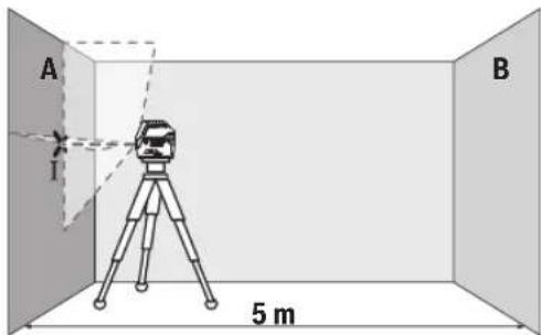
- Cnpmyte na3ep Ha 6nky CTHy A Ta daIte Nomy HBeIIOBATNC. Po3NaTe cepEnHy TOK, B KII Na3epHI liHII nepexpeuOyTOBC HA CTHi (TOka1).

Bi3nHHI (31) nokpaUyE BnHmictb naeepHoro npomeHIO npn HecnpaTINBnx yMOBaX Ta Ha BeNkNx BiCTaHx.
NobepxH B3nphoro 31)0Bic3epkaioc, nokpaue BVnIMcTb na3ephoI liHH, uepe3 npo3opy nobepxHIO na3epHy nHIO TAKOX BnHO 3 TnHBO 6Oky bi3npHO 5HTa.
Pobota 3i wtaTbOM (npnlaa)
WtataHB 3a6e3neueccta6inbHy niCTabky dN BmipHOBaHHBnCOTy kkoMOKHa peynBOaTH. NocTaBE BmipOBAhHINCTpyMeHT H13DOM NiD WtATNB 1/4" (18) HA p3b6y wtaTNa
(32) a60 3BnauHORo FOToUHTaTbA. 3afoikcyte BmipOBaIbHInCTpyMeNT KpINbHm FBHTOM UTAbTa
Ipyo BnpiBnHnTe 1tAtnB, nepu HIX BMnKaTn BmipOBAhBN npnna.
Φikcaia 3a donomoro yhibepcainbHoro KpinneHHa (npnaad) (nB.Man.L)
3a donomoro yHibepcaIbHOro KpInneHHA (26) MoKHa 3aipikcyBn BmipHOBaIbHn IHcTpMeHT, HAp., Ha BeptkakbHnx NOBepxHx, Tpy6ax afo HamarHueHHx MaTepiJax. YHibepcaIbHe KpInneHHa MoKHa BHKOPrTOByBAtn TaKox B JKOcTI niCDtABKn. BOHO nonerWyC BpIBHOBAHH npnaJy no BncOTi.
Ipy6o BnpiBnHrTe yHbEpcanbHe KpInneHHa (26), nepu HIX BMKAtu BmipIOBaIbHn IHCTpyMeHT.
P6oTa3 na3epHm npHmauem (npHnadaa) (nB.MaL.L)
3a HecnpnHnBHX yMOB (cBITne cepedOBnue, npame coHnue cBtno) Ta Ha BENKHX BIDCTAHX, 0o6 newe 6yno 3HaHTn IaepHI liHII, KopNCTyIeTcB naepHM npnMaem (29).Pp npo6Oti 3 naepHM npnMaem BMKaTepeKM npmMaay (NB. Pekm npnMaayC, CToPiKa 208).
Okynpn npo60TH 3 na3epom (npnaad)
Okynprn npo6oTH 3 naepeom BiDipinbTpoByIO bCITNO 3OBHIHbOro cepedOBuHa. 3aBAnu cboMy Cbitno na3epa 3daETbca nrye CbitniuHm.
He BnKOpNCbOByte OKyIaRn DnIpo60TH 3 na3ePOM (npna)Ak 3axHcHIOkyIaRn. OKyIaRn DnIpo60TH 3 na3ePOM 3abe3neuyIb KpaIe po3ni3HaBaHH Na3epHOro npomeHIO, ODAHKe 3axHuaIbBID Na3epHOro BnIPomHOBAHJ.
He BHKOPNCOTByTe OKyIaRn DnIpo60TH 3 na3epom (pHnaDn) kCohue3axncHi OKyIaRn Ta He BJaRaIte Ix, KONN BH 3hAxOHTecra 3a KepMOM. OKyIaRn DnI po60TH 3 na3epom He 3a6e3neuyoTb NOBHH 3axHCT BiD YΦ npomeniBa Tn poripuyoTb po3ni3HaBaHnKoJIbOpIB.
www.bosch-pt.com/serviceaddresses
TpaHcnopryBaHH
Ha pekomehdoabhi nitiEBO-ioHni akymyIaTOpHi 6aTaapei p03NOBcOJxOToBcBAIMOrn IIOo TpaHCnOpTyBaHH He6e3neuHnx BaHTaxiB. AkymyIaTOpHi 6aTaapei MoKytb nepeBo3NTnCk KopNCtYBaem ABTOmO6IbHm TpaHCnOPTOM 6e3 Notpe6n DotpmaHH DaDTKObHX HOPM.
Pnpecnui tptimn oc6amn (hanp.: nobitprnHm TpaHCnopTOM a6o tpaHCnopTHM ekCneDHTOPOM) notpi6HOdoepkyaBtnc Oc6bNBHX BHMOTO yNakOBKnTa MapkyBaHHa. Y cybomy BNpaKy y nIroTOBci NOHN H 6paTHy uactb ekcept3 He6e3neuHx BaHTaxiB.
BicnaiTe akymyTOpHy baTapeIO nIwe 3
HENOISHKOJKeHM KOpnycom.3aKneIe BIIkPnTI KOHTAKTN Ta 3anakyTe akyMnyTOpHy batapeIO TAK,IO6 BOHa He COBaJaCByyNakOBu.i.DOTPNMyTEcA,6yNb NaCKa,TaKoX MOKNBHX DOdaTKOBHX HauioHOHaBbHx npnncIB.
Ytunizia

BmipioBaIbHI iHCTpyMeHTn, akMyIaTOpN/ 6atapei, npnaJdI yIyakOBky tpeba3aDaBAtn ha ekONOrIuHO uNCTy nobTOPhy nepepoKy.
He BnKdAaTe BmIpOBAJbHi iHCTpyMeHTi aKyMnyTOpHi 6aTapei/6aTaepKNB NObyToBe CMITTA!
IIneIINKpaIH EC:
BidnoiHO do CbponecboKoi DnpeKTHBN 2012/19/EU
Odo BixoDIB eNkTPnuHOro Ta eneKtpoHHoro 6bnaHaHH
Tt II nepeTBOpEHnB H aHIOHaJIbHe 3aKOHoDaCTBO
BmipOBAIbHI iHCTpyMeHTn, Aki Bilhe He npdaTHI DO
BHKOPNCaHHA, a TAKOK BiNDOBiHO Do CbponeCbKOi
DnpeKTHBN 2006/66/EC hecnpaBH a6o BiNpaBoBaHi
akymyIaTOpHI 6atapei/6atapeKn NOBHHI 3dAbatnc
Okpem o ytni3yBatncra EkonoriguHOnu ChTM CNOC6OM.
PnHepaBnHni ytni3auiB iDnpaobAHi eneKtpuHi Ta
eNkTPOHNI npnlaH MoKyb MaTH uKiIDINBn BnNB Ha
HaBKONHHe cpeDoBnue Ta 3dOpOB' IIOHNH Ypeez
MOxNNBy HAABHICTb Hebe3neuHX peOvHN.
Akymnyatophi 6aapei/6aapeKn:
Jitiebo-oHHI:
BydNb Iacka, 3BaKaJte Ha BkaziBKn B pozdiN "TpaHCnOpTyBaHH" (DnB. ,TpaHCnOpTyBaHH, CtopiHa 212).
Ka3ak
Eypa3nna 3KoHOMnKaIbIK OdaftbHa (KeJeH OdaftbHa) Mywe MemLeKeTtep aymarfbHda KOnDaHbIaIbI
HdyinH yin KapaTbPfAH naDanaHy KkaTapbHbH KpaMbHa naDanaHy XeHHeiOcb HcaybK, coBIme bipe KocbMwapnap da bony MykH. Caikecti pactay kainb aKnapat Kocmba da bap. OHmDi eHipre Memneket Tpyabaknapat OhmHIn KopcybHa Jxhe Kocmbuada Kepctinre. OHipireh Mep3i MykaacbHbH coFb 6etinde xhe him KopnycbHa Kepcetinre. HmnpTepre KaTbCTb SaNaHbcaknapat Him KaTamacbHa Kepcetinre.
Ehimi naiandahy Mep3iMi
HIMH Kbl3metety Mep3iM 7 kbl. Hdipinre Hmpimeh
6actan (hnpy kyhi 3aybTTaKaTHwacbiHa Jaa3bnFaH)
ictne5 kbl caTafAHn coH, hIMdi TeKcepyi3
(cepbcik TKeKepy) naDanaHy CbHmMaBbl.
Kb3METKeH HeMeCe NaaDAnaHyBbHbH KATENIKTepi MeH icTe HbIry ce6entepinH t3imi
-0HIM KOPnycbHaH TIKENEI TYTIIN WbIKCa, naJaDaNaHaBaHbI3
JkayBH-7aWbHKe3IHc6bPTTa(daIada) naIdaIah6aHbI3
-Kopnyc iiwhe cy Kipce KypbifbHb Kocyub60MaHb3
Uekri kyn6enrinepi
-0HIM KOPnYCbHbH 3aKbIMdAnybl
Kb3met Kepcety Typi MeH xiniri
OpaandaaHyaH coH eHimDiTa3aJay yCbIbnaDb.
CaKray
KypfakKepe daTay Kepek
KOFapbI TemnepaType Ke3iHcXHe KYN CAYneNepiH 0cepH e anbcakTayKepeK
- cakay kezihne TemnepaTypaHbIH Kehet ayblkbyHaH KOPfay KepeK
-erep Kypan JxMcaK cMke HeMece nactK KeCTe XeTKi3Jnce OHbIOcbI e3IH KOpFaBbIa Ka6bIHda caTay YcbHbIaNabI
- cakay waprtapby typabik Kocbimwa aknapaTanyuH MEMCT 15150-69 (Wapr1) KyaKaTBH KapaHb3
TacbImaay
TacbImaIay Ke3HHe eHIMdi Kynatyra XeKe 3Ke KeIReh MExaHHKaIbIK bKnAn etYe KaTah TbInbIM CaJIbHaBbl
-6ocaty/xykTey Ke3iHne NaekTI KbcatbH MaunHaapn naDanahyFa pyKcat bepinmei.
-TacbImaJay wapTAPbI TaIanTAPbIH MEMCT 15150-69 (5wapt)KyKaTbIH OKbIHbI3.
Kayinci3ik HycKaynapbI

Onwey KypanbimEn Kayinci3 Xhe ceHimdi
Xymbcicteey yinbapnbik
HyckaynbikTapdbokbinOpbHday Kepek.
Onwey Kypanbihocby HcyKaynapra cai
naIanaIaH6ay enwey KypalbHaBfkiPictipinre H Kayinci3ik wapanapbHa Jxbfimcb3 acep etei. Enwey KypalbHaBfleceepTynepei Keipn6eHTIN KbIMMaHb13. OCblHYCKAYAPDbICAKTAN, ENWEY KYPALbIH BACKAJIAPFA BEPTEHEOJAPDbKOCA YCbHbIHb13.
A6aB 60nbHb3 -erep ocblxepde 6epinren naDanaHy HeMece Ty3eTy KypanapbHaH 6acka KypanDaH naDanaHca HeMece 6acka Kymbic aDiptepi opbHdanca 6yn Kaynti ceynere wabHyra anIn Kenyi Mymkn.
Θηωeу KypaIbI na3ep ecKepy TaKtacbImeH 6ipre XeTki3inei (rpaФнka 6etIHderi eNωeу KypaIbIHbH, cypTeHne 6enrInehren).
Erepnaepeckpy TaKtacbHbMmTIHI eniHiaHtinihde60nMaCa,anfaw pet kondaHbIcKa eHri36ec 6ypbH OHbH opbHa eniHiaHtinihderi XancbipMaHbXa6bictbipbHb3.

Ja3ep cayneinci adamapfa Hemece Kahyapnapfa 6afblTamaHb3 Xehe e3iH3 de Tikenei Hemece Wafblbckan Ja3ep Cyaynecine Kapamahb3. By anaMdpdbH Ke3IH Waflblpybi MymKH, cTcI3 OKfanaPfA kenyi Hemece Ke3re 3kblm KeTtipyi MymKH.
Erepnaepcayneci Ke3reTyceKe3epejixymbin 6actbcaynenapkapatykepk.
Na3ep KypbInfbicihda eukhdaa e3repty opbIHdAmhbl3.
- Na3ep Kepy Ke3inDipirih (KepeK-japak) KopraHbIw Ke3inDipiri petiHe naaDaanha6bI. Na3ep Kepy Ke3inDipiri na3ep cayneCIn JaaKcbIpaK Kepy ywiH KonDaHbNad, anaJa n3ep cayneCIneH KopFamaibl.
P3ep Kepy Ke3inDipirin (KepeK-kaK) KynHe K0pTaBtH Ke3inDipik petiHne Hemece K03FaBbCbIHda naIaIaHa6BaHb3. P3ep Kepy Ke3inDipiri ynbTpaKynrHcaynenepeH ToBik K0pTaBbCTb KaMTaMaCbI eTneI JxHe TycI ce3y KaBineH a3aiTabl.
Onwey KypanbH TeK 6iniKi MAmHaFa XHe apHaynb 6eWekTepeMeh XeHdeti3. Con apKbIbI eWey Kypan Kayinciairin caKaTaNbI.
Bananapra na3ep enwey kypanbih 6akbinaycbi3 nainanahyra pykcat etneH3. Onap 6acka adamapdbIH Hemece e3HH Ke3H abaicblaan haafbibictbyb MyMKIH.
KhaHbIH cyhBtBkTap,ra3dap Hemece waH KhbINFAH XapBnBc Kayni 6ap optada enwey KypaBH naDanaHa6bI3. OWeey KypaBly WbKbH WbIFapbln,waHbI KaHdbipIn,epTdybpy MyMKH
AkkymyTopbI aunahbI. Kbicka TybIKTany Kayini 6ap.
214|Ka3aKa
AkkymyTOp 3aKbIMDaIraH HeMece Dpybc IaIaIaHaBImMaHaH KaFdaJa, OaH 6y WbIFBy MymKIn. AkkymyTOp XaHbIn Hemece XapbIn BanyMymKIn. Ta3a aya iIke TaTpBtHi3 JxHe WaBmAp 6oNc, aIpirepNiKemeri He KyrinH3. By TbHbC any KonDapbIH TitIPKeHdipy MymKIn.
AkkymyITopDpybc NaiaDanaHbImaHaH HeMece 3aKbIMdAnFah XaFdaJa, aKKMyIToppaH cybIKtbK aBybl MymKIn. OfAH TmEi3. Ke3eicOcTepire TReHe, coJxepDi cyMeH WaiBbHb3. CybIKTBk K93re TnCe, MeHHuHaNbIK KEmek aIbHbI3. AkkymyITopdaFbCybIKtbK, tepHi TitipKeHdipyi Hemece KyIipyi MyMKIn.
Were Hemece 6ypaybi ciKtbi yuTbi 3aTTap Hemece cbiptkbi cep apkblb i AKKMyyIANTop 3akbIMdaHybl MyMKIN. Byi Kbcka TyblkTalyf aBIn Kenin, aKKMyIANTop XaHybl, TyIH bIfapby, XapblNyI Hemece Kb13bn KeTyI MyMKIN.
PaiDanaHbIMaHTbIH AKKyMnTOpDbI Tyicnenepei TYbIKTaybi MYMKIN KbICtBIPfBiITapDaH, TbIHdApDah,KiTTepDeH,WereNepDen,BHNTePden Xhe 6acka Ycak Temip 3ATTapHaN CaKtaHbI. AKyMnTOp TYicnenepiH apacbHaFb KbcKa TybIKTany KyikTepre Hemece optKe kenyi MYkH.
BnyakymyIaTOpIbTeKKaHaOcbEhDipyi eHIMepiHne naDaIaNbIb3.CoApkbIbI aKKMyIaTOpIbKayinti,apTbIKKytKeYdeHcaKaTaIcbl3.
AkkymyIaTOpnb6aTaepnHbTeKeHdpyWi KepcTeKe3apdTay KypbnfbcbImeh 3apdTaHb3. 3apdTay Kypbnfbcbl6enrini 6ip akkymyIaTOpnapTypine apHaHanfaH,Onb6acKa akkymyIaTOpnapbl3apdTaYuHn naDanaHy ept KayinH tybipaB.

AkkymytnTopbl, kblnydaH, cohdai-ak, Mbicalbl, y3diKc3 KYN kapbIfbHaH, OTTaH, KipdeH, cydah XHe bInFaIaH KopFaHbI3. Xkapblbc XHe Kbicka TybIKany Kayni TybHdaBbl.

OJwey KypalbIH XHe MaHHTIK KepeKXapaKTapdbI HmNnHaTtAPdbIH XHeKapdnoCTHMpyIaTOp HeMece HNCyINCOPfbIcbl CnAeTbI backaDa MeDnHnHaBbIK KypblfIaPdbIH KaHbHa KoMaHbI3. OJwey KypalbIMeHKepeK-kaPaKTapdbIH MaHHTepi HmNnHaTtAPdbIH XHeMeDnHnHaBbIK KypblfIaPdbIH KymbIcblHaacep etetih epic tybpabI.
Θnwey KypalbMeH MaHHTTI akceccyapdbMaHHTIK depeK TaBbIbTAP MeH MaHHTKe ce3imTan KypbInfbIpadHa anwak YcTaHbI3. Θnwey KypalbMeH akceccyap MarHHTepiH acepi depekTeprIH KaTbIMCbI3 KOblNyibaHa eKenyi MymkiH.
AkkymytnopblHemece6atapennapblbEwey KypalbIme6apblkXymbICTapbl(Mblicanbl,opnaty, KbI3MeTKepeCey,T.6.)6actay andbHa,cohdai-ak, Owwey KypalbIHTacbImaIay XHe caKtay Kezihde WbIFapblbI3.Kocbl/ewipriuke KeaeicokTIOXapaKaattAHy KayniH TyblpaBl.
A6ai 6o1h13! OIwey KypanbHn Bluteoth6eH naDanahyda 6acka Kypannapm Hen Ka6bIKTap, ywaK xhe MeuHNHaBik Kypanlap (Mbicnbl, kapnoCTMMyTApOp, ccty Kypanl4bp) KymbcihDa Keeprinep naDaa 6onyb MyMkIn. Cohdai-ak XaKbIH TypFaH aamap Men XaYaNapf3HH TyDbipy KayinH ToBikXOIO MymKIN emec. OIwey KypanbHn Bluetooth6eH MeuHNHaBik Kypanlap, XaHap MaJ 6ekETepi, XmNraBik Xa6bIKTap, Kapbiny Kayni6ap XeH JapBnATbH aiMaKTap XaHbHna naDanaHb13. OIwey KypanbHn Bluteoth6eH ywaKTapda naDanaHb13. DeHere XaKbIH aiMaKTa y3ak yaKbIT naDanaHb13.
Bluetooth® ce3 genrici, cohdai-ak cypert genrinepi (norotintep) Bluetooth SLG, Inc KOMnahancbihin tipkenreh cayda genrinepi xane xke mehuiri 60bn tabbina.Obc ce3/cypert genricinH Robert Bosch Power Tools GmbH TapanbHaH ep KOndaHbIybl niuehenia 6oibHwa kyyere acadbl.
Θhim KəHe KyaT CnnaTTamacbl
Painanany Hcyckaynbifbihn anfbi 6nirinH cypeTepiH ecepiH3.
Taraihdaany6oibinaKoandahy
Oney Kypalbl KeIeHeH XeHe TIK Cb3bKTapbl XHe NepnEnkyIep Heri3epin ecenten TeKcepyre apHaIFaH. Oney Kypalbl iKi MeH cbiptkbl aMakTapda naJaIaNHyFa apHaIFaH.
RM26ypama yctaftbHbHkKemerImeH enIwe kypaBnIH 360-kaapdaibm KepiHTeH opTaBik, npeHnkyJnR HerizhiH anHaNaCbHda 6ypayFa 6oJa. Ocbiaa naep cb3bIKTapbl dAn TypanaHaBla da, enIwe kypaBhlBnOpHaNacBye3repMeNi.
KopceTirren Kypamdb6nweekTeP
Kepcetireh KypamdaCTap Hemipi cypTep 6ap 6teri enIwey KypaBbHbH CnnaTTaMaCbHa KaTbICTbl.
(1) BaftTaybiOuBik
(2) AxbipaTkbii
(3) Na3ep cayneciHHbIbIc aHbIaaybI
(4) AkkymyTop/6atapennap 3apbIbHIn DeHreIi
(5)MaTHnKti6yFaTTayHnDnKaTOpbl
(6)Ka6bɪnɪdʌfbiɪwpejxɪm Tynmeci
(7) Ka6bɪnɪdaɪfɪwpejxɪmɪnɪdɪkɑtɒpɪ
(8) NaapeKyMbicpekHmIe aPhaIHaT TymE
(9)Bluetooth®apkblb6aHnHaHbcHnDnKaToptb
(10)BluetoothTMyMeci
(11) Akkymyntop 6enimi
(12) AKKyMnyTOpa
(13) BaTapea aanTepeiH Kabba
(14) BaTapeaIap
(15) AKKyMnyTOp/6aTaper aanTepiHbocaty TVIMecia
(16) BaTApE aIaIaTePiHJXaNkblbIa)
(17) Na3ep eckepy TaKtacbi
(18) ⅢtaTMB6ekitkiu,1/4dHIM
(19) CepnIbIK HEmip
(20) BaftiTaybiIi ShnHa
(21)MaTHHTa
(22) BoiIbIK 6ekITKiI caHbIaNaya
(23) Bypama yctarbiw
(24) Bypama yctaftbIHTbH dAnen peTtey bpaHaacba
(25)Te6eKancbipMpcb(a)
(26) Θm6e6an yctafblu
(27) AynHnMa nnaTΦopMa
(28) KaawbikTanh backapnynbltn
(29) Na3eprKa6bInaBfAibpa1
(30) Μλερ κεργκεδιπίριρια
(31) Na3ep HbICaHbIK TaKTabc)
(32)UHTaTHB
(33) TeneckonTbik KapHaKa3
(34)KopFaHbIwKaTnTa
(35)Багаряадптepi
(36) ⅢaδaπaH
a)GeHeneHReH HemeCnTaTaNfH K6bIKTap cTaNapTTbI XeKTI3y K0enMImEH KAMTBIMMaBb. ToNtBkKa6bIKTapDbI 6iDIn Ka6bIKTap 6afapnAmMbI3an Ta6acbl3.
TexHnKanbIK mAnimetTep
| Hyukteni XXeHne sbIbIKtBik Ia3ep GCL 2-50 C GCL 2-50 CG | ||
| ФИМ HOMPI | 3601 K66 G.. 3601 K66 H.. | |
| ЖуMbIC aIIMaFBI A) | ||
| - СтандарТы пазер сbl3bIKTapbl 20 M 20 M | ||
| - Пазер каблдагышимen 5-50 M 5-50 M | ||
| - Хогары karapatыган пазер hykteci 10 M 10 M | ||
| - Төмен karapatыган пazер hykteci 10 M 10 M | ||
| Нивелирей undДirig(BC) | ||
| - Пазер сbl3bIKTapbl ±0,3 MM/M ±0,3 MM/M | ||
| - Пазер hykteleri ±0,7 MM/M ±0,7 MM/M | ||
| Ödettere i eždirinien Hnibelenrpey dlnanazohb | ±4° ±4° | |
| Ödettere i nivelniprey yakbItb < 4 c < 4 c | ||
| Herizri biKtikTih yctinderi maks. naДалану biKtiri | 2000 M 2000 M | |
| Салысторmaы aya bInFaIbIbIbIbIbIbIbIbIbIbIbIbIbIbIbIbIbIbIbIbIbIbIbIbIbIbIbIbIbIbIbIbIbIbIbIbIbIbIbIbIbIbIbIbIbIbIbIbIbIbI | 90% 90% | |
| Ластану дэржесi IEC 61010-1 standarltbбоьншa | 2D) | 2D) |
| Пазер Класы | 2 | 2 |
| Иmsnyльстор жиiliri | ||
| - Каблдагыш ржиминсiaпайдану | 23 кГц | 23 кГц |
| - Каблдагыш ржиминde пайдану | 10 кГц | 10 кГц |
| Пазер сbl3bIFbI | ||
| - Пазер Typi | 630-650 HM, < 10 MBT | 500-540 HM, < 10 MBT |
| - Пазер саулесинчуci | Кызblлжасbl | |
| - C6 | 10 | 10 |
| - Альперmaшык | 50×10 мразд (толыкбурbl) | 50×10 мразд (толыкбурbl) |
| Пазер hykteci | ||
| - Пазер Typi | 630-650 HM, < 1 MBT | 630-650 HM, < 1 MBT |
216|Ka3aKa
HykTei XaHe cb3biktbk naep GCL 2-50 C GCL 2-50 CG
Thiye KypaIbCTaHapTb6atapeRnapMeH He Bosch HINTH-NOHBkAKKymNtOpMeH XyMbIC iTeNi.
AkkymyIaTOpMeH naIdaIaNy
TekTexHkAnbIK MOniMeTepDe Ka3bInFaH 3apdTay KypanDapbH naJaHaNbHbI3. Tek KaHa oCbI 3apdTay KypanDapbI ci3iH eJlwey KypaBbHb3dbH iHiHe NHTINHOHBik AkkyMnyTopMeH caikec.
Hcy:Onwey KypanbHb3ra apHaMaFAaKKymnTOpdb naDanaHy eIwey KypanbHbH KATE XMybIC icTeYiHE HEmec 3aKbIMdahybHa anBn Keyi MyMKIH.
Hcyak: aKKyMnTOp iHInapa 3apdTaFaN Kyide KETKlnei. AKKyMnTOpDbH TObIK KyatbH naIaHaHyuH OHbI anFaW pet naIdaHaHydAanDbH ToBk 3apdTaHbI.
HINHNOHBkAKKMyIaTOpblnAaJaHaMyMep3iIMH KbICAPyCbI3 Ke3 KeIReH yaKbITTa 3aprTayfa 6oJaDb. 3aprTay npueciH y3aKKMyIaTOpdbH 3akbIMdAnybiHa eKeMeNdi.
IINH-NOHBk AKKyMnTOp 3eKTPoHDbK 3JeMeHTepi Kopray "Electronic Cell Protection (ECP)" apKbInb Tepeh 3apd JxofAynH KoprAnFAn. AKKyMnTOpBn TOrb6itCe, Kopray Kymeci Onwey Kypalb H eWipei.
Kopfbaiwewipriwuewipinrenhencoh enwey KypanbH Kaeta Kocnab3. 8ntnece aKKymyIaTOp 3aKbIMdHaHybl MykH.
3apraTanFaH akymyIaTOpbl (12) opHaty yuH OHbl aKymyIaTOp 6eimuecihe (11) ceinin tipenreHwe XblXblTbHb3.
AkkymyIaTOpIb1 (12) wIbIapy yIiN 6OcAty nepHepePi (15) 6acBn aKKMyIaTOpIbI aKKMyIaTOp 6eIMueCInE (11) WbIFApbHb3. OcbI Ke3de KUw caMaHbI3.
BaTapeHapMeH naiDanaHy
Ouwe KypaIbI yin Ankainn MapraHe 6atapencbH naananahy CbHbnaBbl.
BaTapeJnap BaTapea aanTepine caIbHaDbI.
Batape aanntepi tek ticti Bosch tekepy kamepaBH naDanahya aphanfah 60bn 3neKtp KypandapbImeH naDanahya 60mai.
BatapeenapbIcanyuHbatae aanTepiHka6bH (13) aKKMyJrTOp 6nIMueCHe (11)XbIXbITbHb3.
BatapeenapbIka6yKaKnafbHdaFb1(16)cypETe KepcetinreHdeKanKa cAnbH3.Ka6yKaNfaBH Kan yCTiHeCceiTeIH pete TipeReHwe KblNbTbH3.

BaTapea npab any yuH auy (14)
nepHenepi(15)KabyKaNfBnDa bacbn, Kaby KaNfBn(16)Taptbn KoBbHb3. BaTapea npabH sbfbn KeTneyiHe Ke3 KekiaiH3. On yuih eWey KpaBnH
akymynap06nimueciH(11)Kofapbifa KapaTbIn yTaHb3.
BaTapeaNapdbAnbIN KOHBiH3.IIHeJeaTkaH KaNTbI (13)
akmynap06nimueciH anbIN KOO YUH KAnTbKaH
KaBipfara a3 bacin yCTan, eJIeY KpaBihA H bIfapbH3.
BapbIK BaTapeaRnapdb 6ipEn AnMaCtbPbHb3.Tek 6ip
EHIpuyHHKHe Kyatb6ipEn BatapeaRnapdb
naDanaHbHb3.
- Εηωeγκραπbɪh y3a kγακbɪr nai danaɪh6acahbɪs, 6aṭaperæn bɪ Εηωeγκραπbɪh aɪn wɪfapbɪn aɪbɪhɪbɪ.
¥3ak yaKbT CaKaTaH KαJaIa, ΕηIeey KγpaNbIHdaftb6aTapeJapdbToT 6acybXHe OaPbIH 3apdBe3diH HAYcbly MyMKH.
3apdanykyinHnHnKaTOpbl
3apd DeHReHH HnHnKaTOpbl (4) AkkymyTApnapbH Hemece 6aTapeepanbpH 3apd DeHReHH KepcTei:
| Жарык дюда зардени | |
| Жасын тустi yздіксіз Жарык | 100-75% |
| Сары тустi yздіксіз Жарык | 75-35% |
| Кьзын тустi Жасынылытайтбн Жарык | <35% |
KapbIK KOK-AKKyMnyTOp 6y3blfHa
218|Ka3aKa
Kapbik dnobl3apaa denreini
-Батaperлардынзарды TaycbiFaH
Erep6ataperenaphemecaekkymyntop3apdblaaabibn KeTce na3epcb3bIKTapbIHbHxapbIKTbIFbIakbipIH TEmHeDi.
By3bIraH aKKyMnTOpbl HeMece 6oc 6aTapeRnapblk Kyneik peTte anMaCtbIpbHbI3.
RM 2 6ypama yCTaFbIWBIMeH XyMbIC icTey (A1-A3 cypeTepiH kapaHbI3)
Bypama yctfbltbiH (23) Kemerimeh enwey KypalbiH 360° Ka optaIbIK, apdaiBIM KepiHIN nepneHnkynap HerizHe bypayfa 6oana. OcbnaHa na3ep cb3biktapbi 6aftTanaDa da, enwey KypalbHbH opHanacby e3repmeNdi.
Iaen peTey 6paHacbIMeH (24) TIK naep cb3bKTapBH Heri3ri Hkyenepre dAn 6aftayfa 60aJIb.
OJy KpyanbH 6aftayu OybfH (1) 6ypama ytaftbIH (23) 6aftayu peKacHa (20) KapaTbOpHaBtBu3 XHe enwey KpyanbH NnatopMa TipenreHwe kpi3iH3.
Akkipaty yuhi Hneuwe kypabih Kepi 6aftta 6ypaMa YCTaftbIHTAH bIfapbHb3.
Bypama yctaftbIHTbH opHaanactbipy MymkiHdkTepi:
- Teric aMakTa Tpyda,
-Tik aImakka Ka byan 6ekitirhenne,
-Te6eKaIcBipMaIapbI (25)KEMerImeH MetaII Te6e peKaIapbIHda,
-Магнтердн (21)Кемеримmetanbetterpe.
PaindaIaHy
PaiDanaHyFa eHdipy
Oneyky KypanbH cb3daH XHe TIKeNei KyH caynepeineh caKaTahb3.
Ouwe KypaBHaA pybKwA TemnepaTypa Hemece Temnepatypa 03repictepin hcepi Turi3yre 6onmaIb. OHbl, Mbicnb, abTOMoBnIb iHInde y3ak yaBtKa KaNbpMaHbI. TemnepaTypa 03repictepi Wfbl 6onfaH KafdaJa, anDbIme Hnewe KypaBhlH TypaKTbI TEMnpaTypacBn CaTahB3 XHe JxMbiCTb IXFaTbPmac 6ypbH apDaBIM dAnDik TeKcepiciH eTKi3iH3 (kapaBIs "Onwe KypaBHLHdAnDirH TeKcepY"5et220). AipbkaTa TemnepaTypa Hemece Temnepatypa 03repictepi opBH AnFAH KafdaJa, enlwe KypaBhlH dAnDiRI TeMeHDeey MymkiH.
Θnwey KypaBbH KaTbI cOfBbNyad Hemece Tycydeh caKaTbH3.CbptKbI KyuTI acepnepeH KeiH eJwey KypaBbHbH XMyMbIcBbH JAnFaCTbpydA 6pybH apaBbIM dAnik TeKcepyiOpbHday Kepek (KapaBbI „Θnwey KypaBbHbH DaNirih TeKcepy", Bet 220).
Onwey KypanbH TacbImaaydah andbH OHbIKocbH3. Owye Tep6eny 6eniri 6yfaTana,b, 8nTneceon KaTbpeKeTepde 3aKbIMaIybl MmKIH.
Kocy/ewipy
Ony KypaibH Kocy yinaxbipatkbwTb (2) "On" KyiHe (MaTHNKti 6yFarTay TetirimeH Kymblc icTey yuiH) Hemece "n" KyiHe (HNBENPny ABOMATNkacbIme Hymblc icTey yuiH) KblNkblH. Ony KypaBbIOKcbIraHH KeIN BipDen HbIbapy caBilaynpbHaH (3) na3ep CaynepePi WbIpaabI.
Panaep caynein aadamapra Hemece xahyapnapra 6aftTamaHb3 xHe tinti anbcih 6oncbH xapbk Ceyneinee 03iH3 kapaMaHb3.
OnwekykpaibHewipy yinKockbw/ewipriwiT (2)"Off KynHe XbIbXbIbHb3. Ewipy KeiHne Tep6eny 6norbl Byfattanab.
Kocynb3apnaykypanbH6akbnaycb3 KanbpMaHb3XHe enuey KypanbH naaHaHydcoh ewiipi3. Naep cayneimeh aamdpBnKe3IH 1aFbIbCTbpy MmKiH.
50°C wamacbiHdaFb pykcatetireh MaKc. Kymblc TempepatypacbiHaH acbiPfah KaFaJaDaIa3ep IIObl KoPraHbc yiwH oWeiCi CyBFAHH coEneWey KpaJIb KaHTa Kocblybi MYMKIH.
Uwipy aBToMaTHKacbl
Erep wamameh 120 mHyt iWHe eHwe KypalbHa eW6ip tyme bacbIMaca, eHwe KypaBbA kkyMyIaTOpnapdbH Hemece 6atapenapbIH 3apRbIH caKtay yuH ABOMaTTb Typee eWIn KanabI.
Onwey KpaabH ABOMaTbI eKHe COHa KaTa icKe Kocy yinH, aXbipaTbIbTbI (2) aNdbimEn "Off" KyiHe KxblkbTbIn, codan KeHH enwey KpaabH KaTa icKe KocbHb3 HEmecn anaep Kymbc pexmHin Tymecin (8) bacHb3.
Uipy aTOMaTHKacbH yaKbITwa aXkbIpaTy
Owby ABOMATKacbH eWipy yiw (enwey KypaNbI Kocynbl
bonFaHa) xmbic typnei nepheci (8) kemInde 3 cek.
bacn ycTaHbI. Owby ABOMATKacbE wken Bonca, naep
cayenepi pactay ywiN KbICKa yaBlt KblnbTakbl.
Hcy:KyMbIcTeMnepatypacbl45CwMaacbHaHxorapbl6onca,ewyabTOMaTKacbH 6ydaH 6bnai eWipye60nMaJbI.
ABTomattb 乌ydi benceHdipy yiwin OJwey KypalbH eWipin, KaTaNocbl3.
PaiDanaHy typiH opHaTy
Onuwey kpaanbHa 6ipHeWe Kymbc pexKmI 6ap, onapnB apKe3 aybCTbpya 60ana:
Kbmy Hkytenik Kymbc: Ouwey Kpaan anra Kaapan Keane He XaHe TIK naepnik Cb3bIKTbXaHe Kofapbl XaHe TMeH Kapai Keane He naepnik Cb3bIKTbUbFapabI. Naepnik Cb3bIKTap 906vbyta KnbicaBbl.
-KeIeHc bIbIKbIKXyMbIC: eIwey KypaIbI KeIeHeH naepnik cbIbIKbI anFa Kapai IbIrapabI.
-Tikcb3bIKTBKXYMbIC:enWey KypaBtTiknaepnIK CblkTb anFa KaapanFapadbl.
OJUey KypaIb6eMneOpHaNacKaHnTaIK naepnKcB3bK Te6eJeXOFapfbl NaepnK HYKTeEH Xofapbl Kepctinei.
OneykypaanbHtikeenKa6bipraJaOpHaanactbipraHaTik na3epnIK cb3bIK TonbIK depnik aHaHaanblk na3epnIK cb3bIKbTI (360cb3bIFbIH) WbIfapadbl.
-HyKTeiK Xymbic: eUwey KpaBti TIK naepnik HkyTeHi Kofapbi XeH TeMeH Kapai Wblfapadbl.
HykTei JyMbIC pekmHc6aKapbIKyMbIC peKmepiH HBeHnPney aBOMaTHKacbIMeH De, MaTHNKTI 6yFATTay TetirimeH de TaHdayFa 6oanabl.
XyMbICpeKmIH aybIcIbpy yuH naep KymbicpeKmIH TYMeciH (8)6acbHb3.
Hbennpney abTomakacbImeHxymbcictey
| Жуmbic kaadamapbihin peTTiniri KeIydenen | Tik сызбтбд Жуmbic pexhmi | Hykteni Жуmbic pexhmi | Маянктɪ 6уfasгay Инданаторь (5) | Cypet |
| Ажырату(b)(2)"n" кунde | ●●● | B | ||
| Ки blысу peхнмi | ||||
| Laser Laser Laser Laser Laser Laser Laser Laser Laser Laser Laser Laser Laser Laser Laser Laser Laser Laser Laser Laser Laser Laser Laser Laser Laser Laser Laser Laser Laser Laser Laser Laser Laser Laser Khymbic pexhmi pexhmi pexhmi pexhmi pexhmi pexhmi pexhmi pexhmi pexhmi pexhmi pexhmi pexhmi pexhmi pexhmi pexhmi pexhmi pexhmi pexhmi pexhmi pexhmi pexhmi PEXHMI | ●-● | C | ||
| -●- | D | |||
| -●- | E | |||
| -●● | B | |||
| Kиblысу peхнm i |
HnBEnInpney aBToMaTnKacbImeH JyMbic icTeReHeIe
"MaTHNKTI 6yFATTay TeteIRMeH Kymbic icTeey" (aXbIpaTbIi (2) "On" KyIHHe) pexnmihe aybcCaHb3,
ocbypeKHMHHdkaTOpnapbHbH6ipiHti tipkecIM MymkiHdiirapdaHbim ickeKocblnabbl.
MaTHMKTI 6yFaTTay TetirimeH xMybIc iTeY
| Жуmbic kaadamapbihin peTTiniri KeLDenen | Tik cbl3bIKTBiK Жуmbic pexnimi | Hykteni Жуmbic pexnimi | MaHTNKTI 6yfaTTay HndNKatOpbl (5) | Cypet |
| АжыраTkbl (2) "On" Кшдe | ● ● - | F | ||
| КиьлбICу pexnimi | Kbl3bl | |||
| Laser Laser Laser Laser Laser Laser Laser Laser Laser Laser Laser Laser Laser Laser Laser Laser Laser Laser Laser Laser Laser Laser Laser Laser Laser Laser Laser Laser Laser Laser Laser Laser Laser Laser Knymehi (8) 3 pet 6acy | ● - - | Kbl3bl | ||
| - ● - | Kbl3bl | |||
| ● ● - | Kbl3bl | |||
| KиьлбICу pexnimi | Kbl3bl |
MaTHNKTI 6yFATTayTeTIRIMEH Kymblc ictereHne "HbEnHpny aBOMaTHKacbIme Hymblc ictey"
(aKbpaTkbu (2) "n" KyinHpeXmHpe aybcacHb3,OCbpeXm HnMkatoPnpabHbH biipihi TipKecIM MymkiHdi npaBbIM icke Kocbna.
Ka6bɪnɪdərɪbɪwpeXHm
Ja3ep Ka6bIaFbIbIMeH (29) Kymbc iTey yuHnnaHaHy Typihe 6aHaNaHbIcB3 Ka6bIaFbIw peKHMdi6encenDipyre 6oana.
Ka6bIndaFbIpeKHMde na3ep cb3bIKtapbl KOFapbl KINiIKTe KblbnBkTan,na3ep Ka6bIndaFbIbIyuHIN (29) KepiHETIN 6onadbl.
Kabindaftpexnmi Kocy yuiH KabindaftpipexnmiH (6) nepheci 6acbiH3. KaBnay pexnmi (7) HndkaTOpbl kacbl TycTe KaHaBl.
Aaam Kei yuH KabIbIaBbIpeKHM Kocybl60nFaHda na3ep cb3bIKTapbHbH KepHici TMeHdetineI. Na3ep Ka6bIbIaBbIbICb3 Kymbc icTeReHde Ka6bIbIaBbIpeKHMdi
220|Ka3aKa
(6)TMyMeueCinKaIa 6acbin ewiipih3.Ka6bIaFbiw peKMIH (7) KepcetKiWi eWdi.
HNBENHPney ABTomAtKacbi
Hbennpney aBTOMaTHKacbImeH Kymbic icTey (B-E cypeTtepin Kapahbi3)
OIIwey KypabibH KJIeHeH XblXbIMaNTbIH Ta6 KOblHbI3 Hemece 6ypama YCTaftTa (23) 6eki
HnBeHnIpyeABtOMaTnKacbImeHxMbICICTeyuHINKCKbI/ euiipriwi(2)"n"kyiHe Kblkblh3.
HnBeInpney ABTomAtHKacb ± 4^ e3 HnBeInpney aHaMaFbHdaFb Teric emeCTIKTePdi ABOMaTbTeri
Ja3ep Caynepei KblnbiaKtaaydaIaKtaca,Onwey Kypanbl HbennpneHreH 60nabl.
ABTomattI TypHe HnBeHnpney MyMKIn 60Imaca, Mbicanbl,
OJwey Kypanbl TpyFaH 6et KeJeHeh Cb3bIKTaH 4
WamacBHaH apTbK ayBtKbIraH 6oNca, na3ep caynepei
KbIaAM KbIbNbIKTaIbI.
BykafdaaOnwey KpaBbH KeJeHeHHeH KoBb, 3zirih HnBEnpney aKtAnFaHa WkyTl3. OIwey KpaBb ± 4^ 3zirih HnBEnpney aMafbHda Tpyca, na3ep Cayenepi ydiKi3iKaHaDbI.
Painanahy Ke3iHne Kaflnbictap 60nca Hemece Kyn e3repce 8nwey Kypanbl ABtOMaTb peTte 93in HINBENPnEi.
HnBeInpNeyEn COH enwey KypalnbHbXkbNxbyapKbNb naa 60nyb MyMKIN KaTepePiAnBbH any yuH na3epNk cb3bIKTapdbH KyIH Heri3ri HYKTenepre caIbCTbPbIN TeKcepiH3.
MaTHMKTI6yTaTTayTetirImEHxMbICictey (FCypetIHkapaHbI3)
MaTHnKti Byfattay TetirimEn Kxmbic icTey yuiH
aXbipAtkbiTb(2)On"kyiHe XbIbIKbIbHbI. MaTHNKTI 6yfattay INHikKatOpbi(5) Kbl3bn TYcneH XaHbIn Typadbl XeHe Na3ep Cbi3bKTabpl6Ory XblnbItKaTaNbl.
MaTHNKTI 6yFATTayTeTIRImeK yMbIC icTeReH Ke3e, HBeBnnpney abTomAtNKacbl eipipinei. Ouwe KypaBbH epKin Konda YCTayFa HeMece EHC 6etke KOFOBaONAbbl.
Ja3ep cayenepe 6ydaH 6bna HnBennpneH6eNi Xahe 6ip-6ipine TiriHeH eTnei.
Bluetooth® apKbInbI KaBbIKTah 6ackapy
Onuwey Kypanbl BluetoothModynimeH ka6biktanfah, on paNIO apKbIb CMapTFOHH Bluteoth HHTepfeci apKbIb KaBkTaH BacApyFMyMKiHdk 6epei.
Bluetooth® 6aainhaibcby yuih tanan etinetih kyyenik anfbiuapTAP typaiiww.bosch-pt.com Bosch HHTephet TopabHda Tabacb3.
Bluetooth@apkbnblKaawbKTHaB6ackapydaMo6nHbIcoHfB KpybNfBMeH enwey Kypanbl apacbHda KaMaH Ka6bNday wapTarpbl naDa 6oNaBl.
KaawbKaTH backapy ywiH Bosch kondaanapbl (Apps) KonkeTImi. Ohbi akpiFb Kypbnfbfa 6aHaNbictb Tnicti dyKeHepDen kkyTe n anyFa 60nabI:

Download on the
App Store

GETITON
Google Play
Bluetooth® kocy
Bluetooth® Kaalbiktan backapyra Kocy yinbl Bluetooth® TymeiriH (10) 6acbHb3. MoNbIbIkypanbHb3da Bluetooth® yAubfBHBn 6eNceHdi 6onybH KaMTamacbi3 etiH3.
Bosch 6aFapnamnapbH 6actaydah coh moNbbl Kypalme H enwey Kypalb apacbHa da bainhaic kacaIadbl. Biphewe 6encndi enwey Kypalts Tabinca Kepekti enwey Kypalbin TaHdaH3.Erep 6encndi enwey Kypalts Tabinca 6aanblic ABOMATb peTte XacanaIabl.
Bluetooth® KepcTeKici (9) XaHaJa 6aHaNaHbIc 6ap 6oNaIbI.
Bluetooth® BaaNaHbIcB 0nUe KpyanBi MeN MoBnIbI COHfBi KpybnIbI apacBHaFbY 3aKa KaBbIKbH Hemece KepePri XaHe
3neKpMaHrHTtik aKaynbK Ke3epei Ce6e6iHe Y3inyi MyMkiH.
Byn XaFaJaDl BluTooth® KepcTeKici (9) XbInbIbIKTaIbI.
Bluetooth® eupipy
Bluetooth® KaawbikTah backapy yiwih owiPy wiwih Bluetooth® TyMeiwirH (10) 6acbHb3 Hemece enwey Kypalh owiPiHj3.
Onweky KypaibHbH, dAndiirTeKcepy
Дандik acepnepi
Kopway TemnepatypacbIe KUtiacep etei. EeHdien Kofapbfa 6oJraH Temnpatypa e3repictep na3ep cayncin aybTKybi MymkIH.
EeH KaBbHbHa Temnepatypa 03repictepi KaTb6oNfaHb YIIN eIwey KpaIbH 20 M KaBbIKtBtAH 6actan WtATNBKe opHAty KepeK. OIwey KpaIbH MyMKIHwIK 6oBbHwa KMybC aMAmFbHbH,OPTacbHa KoBbHb3.
CbIPTbI acepnpenTbIc acnantbIK acepnpe De (Mbicnb KaftlbIC Hemece KaTbI cokkbipap ayltkynapFa anbin Keniyi MymkiH. CoYwIH ap KymbICTaH anDbH HNBENPney dndirih TeKcepH3.
AaBIMeH KAnIeHeH Na3ep CbIbIbHbH 6nIKTK XaHe HBeInpNeY dAnirH, an cOaN H KeIH TIK Na3ep CbIbIbHbH HBeInpNeY dAnirH XaHE BepTKaN b DAnirH TeKcepIN WbIFbHb3.
Erep enuwey kpaanb tekcepy Ke3iHne MaKcMaIbbl ayltkydAn acbIpcA, OHBI Bosch cepBnCTIK optanbIfbIHda KHeHTeTih3.
KoIeHEn Cb3bIKtBn 6nikTik dAndirin Tekcepy
Tekcepy yuH 5 M 6oc eHwey KaabkTbIfk KaTbI Kepde A MeH Beki Ka6bipraHbH apacbHa da Kepek bonaDb.
-0nuey Kpypabih A Kabbpfcabihh XaHbHdaBfI WtaTNBKe Hemece KaTbTeric 6etke opHaTbH3.0nuey Kpypabih
Kocblb3.HBEnHpey aBTOMaTHKaCbMeH KbIcy Kymblc peKMIn TaHaBl3.
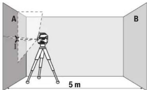
-Ja3epdiJkaKbIH A ka6bIpFaCbHa 6aBfTTan, OJIwey KypaIbH HnBEnHpNeH3. Ja3ep cb3bIKTapb Ka6bIpFada aKbIiW-YuKbI W HyKTeciHOpTaBH 6enrIneH3 (IHyKTeci).
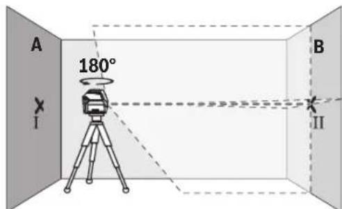
-Onuwe KypanbH 1806ypan,OnbH HnBEnHpnen Na3ep cb3bIKapbHbH apfbl BKa6bpFacbiHdaFbl aKbIi-MyKbIHyKTecih BenrineH3 (II HyKTeci).
-0nuey KpaBbH 6bpamB BKa6bIpracbHbH KaCbHda KoBbN, KcBbHb3 da HNBennpneH3.

-0nuey KpansbHbH 6nKtirH (WtTaHBep HeMece 6ap 6oIca tipeyii Kemerim) na3ep cb3bIKTapbIHbH aIKblu YKbIi HYKTcB i Ka6bpFacbHa anDbimE 6enrInre HHyKTere II cAIEKC 6oNaTbHdAn 6aftTbH3.
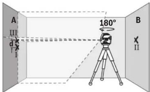
-0nwey KypalbH 1806ypan 6nikTirih 03reptneH3. Ohbl A Ka6bipracbHa TIK naep cb3bfb6enrireHRe HkyteciH eTeiH erin 6afbbTTaHb3.0nwey KypalbH HBeHpIe, naep cb3bKTapbHbH aKiWi-yKbiH HkyteciA Ka6bipracbHaDa (III Hkyteci) 6enrineH3.
A ka6bipfacbiHdafbI MeH III eKiBenrineHRe HkyTeHH d aibipMaBblbFbElnwey KpaBhlbHdN 6nIKTIKeH aybiTKybH KepeTeJI.
2× 5M = 10 m enIwey KaIbIKtbIFbIHdaFblpyKcATetINReH MaKCHMaNDbaybITky:
10M×±0,3MM/M=±3MM.ImeHIII HYKTeNepi apacbHaFbdaibpMaBbIbFbE hKe6i 3 MM Kpybi TnC.
KoIeHeH cb3bIKtbH HnBENHpny dAnirH TeKcepy
TeKcepy Ywih Wam. 5× 5 M6oc KeHjcTik Kepek.
www.bosch-pt.com/serviceaddresses
TacbImaay
YcbHbIFaH IINTH-NHOHBkAKKMyJrTOpnap KayiTI Tayapnapra KOBblaTbH TaanTAPfa 6aBHaNb. PaAnaHyblA kKKMyJrTOpnapDb KeWeDe KocBIMaa KKaTAPcB3 TaCImJa anaBl.
YiwHwIyTnFanapMbicanb,ayeKnliriHemeceXibepy) opamaraJxHe MapkanaPra KOnblnabH apHaBt TaanTapdbCaKaTay Kepe.KiibepyRe daBihDay Ke3InDe Kayinti KyKTepiTacbImaay MAmahbEm Hxa6apnacyKepe.
AkkymyIaTOpIbI Kopnycbl 3akblmdaIHaB0nca fHa
Xi6epiH3. Aushk tyicnepej iKeimdeH3 Kahe
aakkymyIaTOpbl opamada Ko3faMaMtbHdApHaH3. KaKet
60nca, KocblMa yttbIepekepepeDl caKaTah3.
Kadere kapaTy

Thiwey KypanbH, AkkymnTOpbH/
6aTapeenapbH, OHbH Ka6DbIKTapbI MeH opamcbH KopwaFaH opTaHb KOpFaHbH peTte KaDeE KapaTy opHbHa TaNCbipy KaKeT.
OneyuKpyanapbHxHeaKkymyTOpnpabbl/ 6atapeenapbIy KOKbIcHa TaCTaMaHb3!
Tek kaHa EO enepi yuin:
EckneKtpnik XHe 3NeKtpoHbIK KypblfIap Typanbl 2012/19/EU eyponaBik DnpkeKTHBaCbi XHe OhBiYNTbIK 3aHHaMaKaONdaHbIybi6ObIHwa naNdanaHyra6yDaH
6bilaJxapamcb3eIweyKpaanapbHxhe 2006/66/EC eyponabIKnpeKTHBaCb6oBHnHa3aKbIMdAnFaH HeMececkipreh akymyTOpnapdb/6atapeennapdb6neKxHan, KopwaHan opta yin Kayincia KOnmEn KaTa enDeye Te xibepy KaXet.
Kate konmeH kadere japaTbnfah ecki 3neKtpnik XaHe 3neKtpOnDbIK KypbIbnfAp Kayinti 3attapdbH 6ony MymkiHirige bainahhictb Kopwafan optafa XaHe aam DeHCaynbfbHa 3HHdbA cep TNI3yIMyMKIN.
AkkymytnTopnap/6atapennap:
JIITM-HOHBK:
TacbImaay6eimHderi,6etHderi HcaynapdbOpbHa3(KapaHb3,TacbMaay",Bet 224)cehcopnbIke npHeMepeTaH3.
Româna
Instruktiuni de siguranta

- Functionare in modul Receptor 10 kHz 10 kHz
Linielaser
-Tip laser 630 - 650nm, < 10mW500 - 540nm, < 10mW
- Acumulator (litiu-ion)
10.8V/12V
-Baterii (alcaline cu mangan)
-Compatibilitate Bluetooth® 4.2 (Classic sI Low Energy)Bluetooth® 4.2 (Classic sI Low Energy)
-Gama freventelore lucru 2402-2480 MHz 2402-2480 MHz
- Puterea maxima de emisie 2,5 mW 2,5 mW
Smartphone cu Bluetooth®
-Compatibilitate Bluetooth® 4.0 (Classic 山 Low Energy)Bluetooth® 4.0 (Classic 山 Low Energy)
- Sistem de operare
Android 6 (si variantele superioare)
iOS 11 (si variantele superioare)
Android 6 (si variantele superioare)
iOS 11 (si variantele superioare)
Greutate conform EPTA-Procedure 01:2014
cu accumulator 0,62 kg 0,62 kg
-cubaterii 0,58kg 0,58 kg
Dimensiuni (lungime x latime x n'taltime)
-fara suport 136× 55× 122mm 136× 55× 122mm
cu suport rotativ 0188x180mm 0188x180mm
Tip de protectie IP 54 (protectie impotrivica prafului si a stropilor de apa) IP 54 (protectie impotrivica prafului si a stropilor de apa)
Temperatura ambienta recomandata in 0^ ...+35°C 0°C...+35°C
timpul incárcárii
Temperatura ambienta admisa in -10^ +50^ - 10^ +50^ timpul functionarii
Temperatura ambienta admisa in -20^ +70^ - 20^ +70^ timpul depositarii
228 Romana
Nivelä laser cu puncte Şi linii GCL 2-50 C GCL 2-50 CG
| Accumulatori recomandi GBA 12V... | (cu exceptia GBA 12V ≥ 4.0 Ah) | GBA 12V... |
| (cu exceptia GBA 12V ≥ 4.0 Ah) | ||
| Incarcatoare recomandate GAL 12... | GAL 12... | |
| GAX 18... | GAX 18... |
Download on the App Store
GET IT ON
Google Play
Activarea functiei Bluetooth®
Service scule electrice
Strada Horia Macelariu Nr. 30-34, sector 1
013937 Bucuresti
www.bosch-pt.com/serviceaddresses
Transport
Accumulatori li tiu-ion recomandi etr ceriintelegislatiei privind transportul marfurilor periculoase.
Accumulatori pot fi transporte rutier fara restricti de catre utilizator.
yka3aHnHa 3a cnryphnoct

3a da pa6oHTe c n3MepBaTeHHn ypeD 6e- 30nacHO h cnrypHo, Tpr6Ba da npooyete H cna3BaTe BCnUKN yka3aHHN. Ako n3MepBaTeHHnTYPed He 6bde n3non3BaN cbO6pa3
Hn Hactounte yka3aHHn, BrpaedHnBe Hero 3aunTHm MexAHmMn Morat da 6bdaT yBpeHn. Hkora He ocTaBnTe npdynpentenHnTe Ta6ENK No n3MePbaTeHHnYpe Da 6bdaT HeeTnHBn.CbXPAHRAIte TPNKINBO TE3N YKA3AHn INI IPEDABAITE 3AEHO C N3MEPBATEHNy UPEJ.
BHHMaHHe - aKc ce H3non3BaT dpyr, pa3nHnO tNoCooeHHe Tk cbOpbXeHHe 3a ynpaBHeHne Hn KaH6-pHpaHe Hn Ce H3BbPwBaT dpyr NpoeDpyr, TOBa MoKe da DoBeE do ONacHO h3naRe He Ha IbueHne.
H3MepBaTeHHrT ypeC ce DocTabra c npeDynpneHrTeHa Ta6eNka 3a Na3ep (B H3o6paXeHHeTo Ha H3MepBaTeHHra ypeHa CTpaHnUata C hrypnte).
Ako TeKCTbT Ha npedynpndntenHaTa Ta6eKa 3a na3ep He e Ha Baunr e3NK, 3aIene TpeHn PbBATA ekcnloatauia OTrope Bbpxy Hero DocTaBeHHc TnKep Ha Baunr e3NK.

He hacoubaite na3epnnaIbkyKbMxopa IN KBNBOTNI BHNMaBaIte Da He NOrneHHe HENocpeDCTBeHO CpeSy na3epnnaIbny IINn CpeSy HerOBO OTPaXKeHne. TaKa MoXeTe Da 3acleniTE xopa,Ja npuHHnTe TpyoBn 3IONoIyKn IIN da npeDu3BkATE yBpeKdaH Ha OUn-Te.
Ako na3epHnT IbU nonaIHe B OuHTe, H3aTBopeTe Bb3MOxHO HAI-6bp3O HOTdpBnHETe TnABTa Cn OT Na3epHHnIb4.
He H3BpUbaIe H3MeHEnHn I0 Ia3epHoTo o6OpyD BaHe.
He n3non3BaIte na3epHnte ouHna (npnHaNDexKHOCT) KATO 3aunTHN OUHNA. Na3epHnte ouHna cnykat 3a no- do6po pa3no3HaBaHe Ha na3epHnra Ib4; Te He npedna3BAt OT na3epHo IbueHne.
He h3noI3BaIte na3epHnte ouHna (npHHaIeXhoCT) KaTO CbHueBn OUYHa HIN npuOoHpaHe. Na3epHnte ouHa He npedlaarat PbIHa UV 3aunTa n HaMaJIraBt Bb3PiMaHETO Ha CBETOBete.
Donyckaite H3MepBaTeHnHrT ypeIa 6bIe peMOHTpancMoOT KBaIIHΦNtpuHnTexHnUcHcMoC n3ON3BAHe HaOpHHaHnPe3epBnYactn.CToBa ce rpaHTnpa 3ana3BaHToHaФyHKuNTe,ocnrypRaUnc 6e3-ONaCHOCTTa Ha H3MepBaTeHNHyaPeI.
He octabraye deca 6e3 npk had3op da pa6oTc n3-MepBaTeHHy ype, Te morat HeBOHDo da 3acnenr Dpy-rn Xopa nn Ce6e cn.
He pa6oTeTe c H3MePbAteHnHa ypeB Cpea C nobH-WeHa OAnchOCT OT EKcNIO3HH, B KOrTo HMa IecHO3a
NaHMM TeHOCn, RaOBe Hn npaxoB. B n3MepBaTeHn Hny ypeN MoT a Bb3HNKHaT NcKpN, KOHT Da Bb3nPaMeHr npaxa nn Napnte.
He oTbapnTe akyMnTaOpHaTa 6aepn. CbuecTByBa ONaCHOCT O T Bb3HNKBAHe Ha KbcO CbeINHHeHne.
Pn noBpeKdahe HnHepaBnHa ekCnnoataun O aKymnatopHaTa 6aTeprn MORat da ce OTdenT nap. AkymnatopHaTa 6aTeprn MOKe da ce 3anann nn da ekcnlonpa. Iorpnke te ca 3a do6po npOBetpBaHe n npOnnKaBAHHe Ce 6bphete KbM nekap. Napte MORAT Da pa3dpa3Hr dHXaTeHNHTe NTHua.
PnH HnPaBnHO n3non3BaHe nHn NOpeDeHa akMyNaTOpHa 6aTepna OT Hea MoKe Da n3Teue eNeKTPoNHT. N36aRbAte KOtAKTa C Hero.AKO BbIpeKn TOBa HA Koxata BN nonaHe eNEKTPoNHT, n3nnakHe TMAcTOO bHnHO c BOa. Ako eNEKTPoNHT nonaHe B OuHTe BN, He3a6abHO ce 06bpHete 3a NmOoi KbM OueH nekap. ENEKTPoNtBT MOKe Da nPeDn3BnKa n3rapnHa Koxa-Ta.
AkyMnyatopHata 6aTepeH MoKe Da 6bJe NOBpeDeHa OT OCTPN PpeMeTH, HApN. INPOHN HIN OTBepTKN, HIN OT CnHHydpH. MoKe Da 6bJe PneH3BnKaHO BbTpeHHO KbcO cBeHHeHHe H AkyMnyatopHata 6aTepeH MoKe Da ce 3aapanH, da 3anyuH, da ekCnNoIpa Hn da ce nper-pee.
Pepna3BaHte HEn3non3BaHnTe akymyNatOpHn 6aTePHN OT KOHTAKC FOrEMNH NmMAnK MAnKN MetaHN PpeMeTH, HApN. KNaMEpH, MOHeTH, KInOYObE, INPOHN, BnHTOBe HdP..TbN KaTO TE MoRAT Da IpeEN3BnKaT KbCo CbeEINHeHne. IocNeCTBnTAOT KbcoTo CbeINHeHne Morat Da 6bDat n3rapHHN nnoXap.
N3non3BaHTe akymyNaTophata 6aTepeHna cMo B npOdykTH Ha npOn3BODHTen. CaMo TaKa TRe e npedna3eHa OT ONaCHO 3a He rnpTeTOBapBaHe.
3apeKdaTe akymyataopnHte 6aTepeHn cmo cb 3apnHHe yctpoCTBa, KOTo ce npenOpBbAT O npoH3BOIDTeJ. Korato H3non3BaTe 3apAHH yctpoCTBa 3a3apeXdHa He HenoDxOJaU NKyMnaTOpHn 6aTeepn, CbIeCTByBa ONaCHOCT OT Bb3HNKBaHe Ha NOkap.

IpeNa3BaIte akymyataOpHATA 6aTePnHa OT BcOKH Tempeatypn, Hapn. BCneCTBHe Na npOdbNkHTeNo H3naIae Ha dHpeKTHa CbHueBa CBETINHa, OrH, MPbCOTn, BOda H OBnAaXHBAHe. Ima ONaCHOCT OT EKCnIO3n H KbCO CbeHHeHHe.

He nocTabnIte H3MepBateHnna ypeH mHarHHTnTe npHHaHneHXoCTn B 6Hn3oCTdo HmnnAHTn HpyrMeHNuHcKn ypeH, KaTO Hanp. nehcmKbpr Hn Hn HcyHOBn NOMn. MarHnTte Ha H3MepBateHnna ypeH nHa npHHaJIeXHOCHTne Cb3daBt NOE, KOEt MOKe Da Hapuyn FyHKUHOHnpaHETo Ha HmIIaHTne Hn MeNUnHCKnTE ypeH.
ДрьхтЕЗМерВATEENHуpeIMMaHTHTNTE npHAnIeXHOCTHa 6e3Oancho pa3CToHHe OT MaHTTHHoCHTENHa HnHΦopMaUnguN uYBcTBNTENH KbMaHTHT-
Hn noneta ypeHn. BcneCTBHe Ha BnHnHnTo Ha MaHHTte Ha n3MepBaTeiHnYpeHn Ha npHaJnEeXHoCTHMeOKe da ce CTnHHe do Heb3BpaTmHa 3ary6a Ha HnΦopMaun.
IpeHn3BbPwBaHe Ha KaKBHTo N da e DeHocTH no H3MEpBaTeHNH ypei (Hanp. MoTHpaHe, TexNHuecko 06cnyKaBeH n dp.n).KAKTo H np TpaHCnOpTnpaH e np6HpAe 3a CxbpaHeHne H3BaXdaTe 06HKHOBeHH Te Hn AkymyNatOPn 6ateHn OT Hero. CbueCTByBa ONaCHOCT OT HapaHBAHe npn 3aDeHCTBaHe Ha NyCKOBHn IpeKcbau No HeBHMaHne.
BHHMaHHe!PnON3BaHToHaN3MepBaTeHNHINCTpyMeHTCBluetootheB3MOXHOcMyuBaHToHa pa60tata HaDpyrHuYCTPOHCTBAHcbOpBXeHNH,CAmoneTH MeuHckn anapath(Hanp.CbpeHn CTmynatopn,CnyxOBn anapath).CbIO TaKa He MoKe Ja ce H3KNUCh EBeHTyAnHO BpeHNO BnHHe Bbpxy Xopa HKBOTHn.He 3nON3BaIte ENEKTPoHnCTpyMeHTa C BkIOueh BluetoothB6nIOCTdo MeuHnCKn anapATn,6EHNHOCTAHUN,XHMNUH CbOpBXeHNH,B3OHNC NOBHeHa ONachOCT OT EKCNIO3HN B6nIOCTdo B3PHBOOnacn MATEpHann. He 3nON3BaIte ENEKTPoHnCTpyMeHTa CBIOUeH BluetoothB CaMonetn. N3-68raBaeTnpOdbNxHTenHaTa pa6OaB HenocpeDCTBeHa 6nIOCT Do TANOTO.
HaHMeHOBaHHeTo Bluetooth® KaKTo H rpaФuHHTe eHemTe (nora) ca perHCTpnpaHH TbPROBcKn MapKn HaΦHpMa Bluetooth SIG, Inc. IOn3BaHTo Ha ToBA HaHMeHOBaHHe N ha rpaФuHHTe eHemTe O ΦHpMa Robert Bosch Power Tools GmbH cTaba no liueh3.
Onncahne Ha npodykta n DeHocCTTa
Moi, hmaTe npedBnH3o6paXeHNrTa B npedHaT aact Ha pkoBOcTB0To 3a paOta.
PpeHa3NaueHne Ha ypeDa
H3mePbTeHNHTypeeIpePnHa3NaueH3aOnpeDnHe H npOBepKa HaXOpH3OHTaHn H BepTnKaJIHnLHHN, KaKTo H NaNTHaOTBeCN.
H3mePbATEHNHTypee nOxOJa3a pa6oHa OTKpITo H B 3aTBOpEH NOMEeHH.
C NOMOHTA Ha BpTAA tae CToKa RM 2 MoKTe da 3aBbTpate H3MepBaTeHnHa ypeHa 360° OKoNo CEHTpaHn, BnHaRn BnHmA OTBeCHA TOcKa. Taka Na3epHnTe IHHN MOrAT da ce HacOyBat ToHo 6e3 Da ce IpomHe I No3uHrTa Ha H3MepBaTeHnHa ypeD.
H306pa3eHH eIemEnTH
HomepnpaHTo Ha enemEnTe ce OTHacn DO n3o6paKeHHe To HA n3MePbATEHnYpeN HcTpaHnUaTcФnpynte.
(1) KaHaJI 3a no3nHOpHpaHe
(2)IyckOB npekbCba
(3) OToBp 3a n3xoJaIyI na3epeHJIbY
(4)CTeneHa3apeDeHocHa6aTepeHnTe/akymynta-TopHnTe 6aTePHn
(5)Индикади maxaIHO apetipahe
(6) ByToH 3a peJHKM C npHeMHNK
(7)ИндikatopЗаразжимсспгшнк
(8) Byton 3a pekima ha pa6oTa Ha na3epa
(9)Инданаця за врьскуюBluetooth®
(10) Byton Bluetooth®
(11) THeaDo 3a akymyIatopHata 6aTepeRn
(12) AkymyataTopha BaTepeRa
(13) BnOxKa aadTep 3a 6aTepeia
(14) BaTepeinn a)
(15) ByToH 3a OTKnHouBaHe Ha akymyNaTopHa 6aTepe/ aanTep a)
(16) Kanaye 3a 3atBapnHe aanTep 3a 6aTepeHa
(17) PpeynpeintenHa tabeKna 3a na3epnna lyb
(18)「He3do 3a MOHTnpaHe KbM CTaTNB 1/4"
(19) CepneH Homep
(20) HanpaBnaBa 7a 7Ha
(21)MaHHTa
(22) Hndlbjxeh O Tbop 3a3aKpeNBaHe
(23)Bbptraa ce ctoKaa
(24) BnHT 3a φHHa HAcTpOHa HA BbPTrAaTa ce CTOnKa
(25) Cko6a 3a TaBaHaH
(26) yHnBepcaneHdbpjkaa3
(27) Bbptraa ce nlaTΦopMa
(28)Дистанционноуnpавпени)
(29) Na3epeH npMeMHNK
(30) ΜαзερΗν Κουηλα³)
(31) Μλαερην Κεηνεν Απούκα
(32) CtANB
(33) TeneckonuHa uHa a
(34)ПпеднанчаHTa)
(35) AaantTeP 3a 6aTePnna
(36) Kyφαρa
a) N3o6pa3eHnTe Ha nHyPHTe HOnnCaHnTe OOnbHHnTENnn pNcNcO6NeHn He Ca BKnIOuEHn B CTaNAPThATA OKOMnNEKtOBk HA ypeHa. N3eepNaTeEN CnCbK Ha DOnbHHnTeHN HnPeCNcO6NeHn MoKeHe Da HAMEPTE CbOTBeTHo B KataIora Hn 3a DOnbHHnTeHN PnCnocO6NeHn.
TexHHueckn daHHN
| Точков и линец постухе GCL 2-50 C GCL 2-50 CG | ||
| Каталожен Homep | 3601 K66 G.. 3601 K66 H.. | |
| РавOTEN obxbatA) | ||
| - Пазерни лини стодартуни 20 m 20 m | ||
| - Слazерни п��имник 5-50 m 5-50 m | ||
| - Пазерни пося на гоpe 10 m 10 m | ||
| - Пазерни пося на дoly 10 m 10 m | ||
| Точост на посыvelларанeeB(C) | ||
| - Пазерни лини ±0,3 mm/m ±0,3 mm/m | ||
| - Пазерни пося ±0,7 mm/m ±0,7 mm/m | ||
| Диапазон на посытчно по посылар- нe, почно | ±4° ±4° | |
| Вреема за посытчно по посылар- нe, почно | < 4 s < 4 s | |
| Мakс. посыта височа над посы- ва височа | 2000 m 2000 m | |
| Ото сени влажно原则上 Мaks. 90 % 90 % | ||
| Стосян на заьрсане сыласно IEC 61010-1 | 2D) | 2D) |
| Клас пазер | 2 | 2 |
| Импунсане чECTOTA | ||
| - Равota бez рожим с п��имник | 23 kHz | 23 kHz |
| - Равota в посы波特овп光照п光照- нik | 10 kHz | 10 kHz |
| Пазерни лини | ||
| - Тир пазер | 630-650 nm, < 10 mW | 500-540 nm, < 10 mW |
238|BbIrapckn
ToykOB nnHeen naep GCL 2-50 C GCL 2-50 CG
| - Κыт ha λазерни льч черveho 3eileho | ||
| - C6 | 10 10 | |
| - Довир提到 50 × 10 mrad (плелен bгл) 50 × 10 mrad (плелен bгл) | ||
| Лазерна точа | ||
| - Ти п лазер 630-650 nm, < 1 mW 630-650 nm, < 1 mW | ||
| - Сыт ha λазерни льч черveho черveho | ||
| - C6 | 1 | 1 |
| - Довир提到 0,8 mrad (плелен bгл) 0,8 mrad (плелен bгл) | ||
| Сывмостима лazерни поемни LR 6, LR 7 LR 7 | ||
| Гиз do за монтурахе кьм сатин | 1/4" 1/4" | |
| Еlec triческо зхарвахе | ||
| - Акуmunаторна батеря (литоев- йонna) | 10,8 V/12 V | 10,8 V/12 V |
| - Батерни (алекално-mангаови) | 4 × 1,5 V LR6 (AA) (садалtersе за вate- рени) | 4 × 1,5 V LR6 (AA) (садалtersе за вate- рени) |
| Пюдьжителност наRobота в pe- ЖИМВICI | Акуmunаторни/об kindкововни ватерни | Акуmunаторни/об kindкововни ватерни |
| - Рожим Крьстocанни ватка | 18 h/10 h | 10 h/4 h |
| - Рожим Крьстocанни ватки | 25 h/16 h | 13 h/6 h |
| - Рожимни | 35 h/28 h | 15 h/12 h |
| - Рожим точа | 60 h/32 h | 60 h/32 h |
| Bluetooth® Имерbatелин урет | ||
| - Сывмостимост | Bluetooth® 4.2 (Classic and Low Energy) F | Bluetooth® 4.2 (Classic and Low Energy)F |
| - РабOTEN чеб�ToEN obxbaT | 2402-2480 MHz | 2402-2480 MHz |
| - Моцност на Ильчаве, макс. 2,5 mW | 2,5 mW | |
| Bluetooth® smapтфОн | ||
| - Сывмостимost | Bluetooth® 4.0 (Classic and Low Energy) F | Bluetooth® 4.0 (Classic and Low Energy)F |
| - Оразционна сисема | Android 6 (и по-нова) | Android 6 (и по-нова) |
| iOS 11 (и по-нова) | iOS 11 (и по-нова) | |
| Maca sbflacno EPTA-Procedure 01:2014 | ||
| - С akуmunatорна ватерия G) | 0,62 kg | 0,62 kg |
| - С batерни | 0,58 kg | 0,58 kg |
| Разерни (дьжина ×ширни × Висуна) | ||
| - Бez дьрач | 136 × 55 × 122 mm | 136 × 55 × 122 mm |
| - С вртаце сстонka | Ø 188 × 180 mm | Ø 188 × 180 mm |
| Клас на зашитыH | IP 54 (эциитен срец пох и ворни- пьски) | IP 54 (эциитен срец пох и ворни- пьски) |
| Пробьчтелнаlemпогура Na околнatable среда по захданe | 0°C ... +35°C | 0°C ... +35°C |
| Дожystimalemпогура Na okolнatable среда по врeme наRobota | -10°C ... +50°C | -10°C ... +50°C |
| Дожystimalemпогура Na okolнatable среда по врeme насхсанe | -20°C ... +70°C | -20°C ... +70°C |
| Пробьчтелны akуmunatорни ватерия | GBA 12V... | GBA 12V... |
| - Сььрпспага Na околнatable среда по захданe | (c ИЗklюочеся Na GBA 12V ≥ 4.0 Ah) | (c ИЗklюочеся Na GBA 12V ≥ 4.0 Ah) |
ToykOB nnHeen naep GCL 2-50 C GCL 2-50 CG
IpenopbutyTeHn3apAHHyCTpoiCt-
GAL 12...
GAL 12...
Ba GAX 18... GAX 18...
A)Пин He6naorponpTHy yCNoBnH (HAnp. HEnocpeCTBeHn CbHueBn LbUn) pa6oTHnT dHaana3OH MoKe Da e NO-MaJIbK.
B) npn 20-25°C
C) NocoueHHTe CTOHOCTH INpEINONAR HOpMaINH NO 6nAoropmTnH yCIOBn HA OKoIHATA Cpea (HaNP. 6e3 Bn6paH, 6e3MbIa, 6e3dM. 6e3 dneKTHO cBHeBO bYeHHe). CnED CNHN TMENepaTyPH KOne6AHN MoKe Da Ce TnHRe Do OTKnHOEHn B ToHOCTTa.
D)Ima camaHnpoBDOHMo 3aMbpCBAHe, npn KoTo e oae e Bb3MOxHO da oe aOKBa BpeMeHHO npuHHeHa npoBOHMoCT npapAn KOHNHS.
E) NO-Kbcn BpeMeHa pa6oTa npn Bluetooth® pexm H/nn npn pa6oTa c RM 3
F) Pnbltooth®-Low-Energy yctpoctBa cnopeM moena H onepaHOnHata CnCTema Moke da He e BB3MOXHO 3rpaXdaHe Ha Bpb3ka. Bluetooth®yctpoctBtata Tp6ba Da noDbpxat npofnna SPP.
G)B3aBnCmOCToH3IOIbHaHataakymyIaTOPha6atepH
H)IITNEBO-NOHHHTAKMYMnATOp H6ATEpMHnHTdAanTePAA1CaN3KNIouHeHOT IP54.
TexnueckntepnapaetnpcaonpeleeneCakymnaTopHaTa6aTePnB, BKIOyeHbOKOMNKeKTOBkata.
3a eHOn3NaHIO nIeHTnФHnIpaHe Ha Baun H3MepBaTeIeH ypeD cnyKc cepHHNHT HOpEp (19) Ha Ta6enKaTa HypeA.
MOnTupaHe
3axpaHbHe Ha n3MepBaTeHnHn HhctpyMeHT
N3mepBateHnHTypeD MoKeJa 6bJe 3axpaHbaH nIc 06nKHOBeH 6aTePnH, nIc C NITHeBO-IOHHa AkymyNaTOpHa 6aTePna Ha Bo.
Pa6ota c akymyataTopha 6aTepeira
N3non3BaIte cmo nocouehnBe Bpa3eJaTexHueck N daHH 3apAHH yCtpoiCTBa.CaMo Te3n 3apAHH yCtpoiCTBa ca napaMeTPh, noXoJxu 3a H3non3BaHaTa BB BaIIH N3MepBateJe hpeIHTHeBO-HoHb6aTePra.
Yka3aHHe: H3nON3BaHETo Ha akyMynatOpHb6ateHH, KOHTO He ca npedHa3auehen 3a Ba7Hn H3MePbaTeen ypeD, MoKe Da npedH3BnKa HepabHnHO My FyHKUHOHPaHc Hn da ro NOBpeH.
Yka3aHHe: AkymnatoPnHa 6aTepe nCe DoCTAB qactuHo 3apeHa. 3a DaIOCTnHETe IbHnna KanaunTet Ha akymnatoPnHa 6aTepe, npEnI PbBoto H3nON3BaHe 3apeTe DOKpaB 3apdHToO yCTPOICTBO.
JIITeBO-IOHHATAkyMylatopH6aTepeRnMoKeJa6bJe3apeKDaHaNoBCAOKBPeMe,6eTTOBaDaCbKpaUaBADbIroTaPaiHOCTTA.NIpeKbCBAHeHa3apeXdAnetoCbIoHeN BpeDn.
IITHeBO-IOHHATA AkyMynaTOpHa 6aTepeR e 3aunTeHa cpeu ybl6oKo pa3peXdaHe ue3 eNeKTPOHHata CnCTeMa "Electronic Cell Protection (ECP)".Pnp pa3peJeha 6aTepeR n3MePBATEHnT ypeD ce H3KnOyBa OT ppeJnaeH npeKbcBau.
Ako n3mepeBATEHnHT ypeD 6bDe n3KnIOueHOT npEINa3HHN ppeKcbau, He FO BKIOUbaHTe OTHOBO. AkymyIatopHATA 6atePMA MoKe Da 6bDe NOpeHeHa.
3a noCTaBHe Ha 3apeHeta akymyntopHa 6aTepeRn (12) BkapaTBe B rHe3dTo (11),doKaTO ycETnTe OTeTnBO npEuppaBAhe.
3a n3BaXdAne Ha akymyNaToPHaTa 6aTepeRn (12) HATNCHeTe OCbo6oxDaBaunte 6yToHn (15) HnDbpnaTe akymyNaToPHaTa 6aTepeRn OT rHe3DoT (11). PnTOBa He npNarAe cnHa.
Pa6oTa c o6nKHOBeHn 6aTePmN
3a 3axpaHbAe Ha 3MepBaTeHnHa ypeI ce npenopbBa H3- non3BaHeTo Ha aKanHO-MaHraHOBn 6aTePN. BaTePnnte Ce noCTaBt B aAnTOp 3a 6aTePN.
AanTopb3a6atehnepeHa3haeHcmo3a non3BaHe B npeBnDEHnte 3a TOBA H3MePbTeHNypeHnHa Bosch nnon3BaHeto My c eNEKtpoHCTpymentn He ce donycka.
3a noCTabHHe Ha 6aTeHNrte BkapaTne KyTHnTa (13) Ha aAnToppa 3a 6aTePNB rHe3DoTo 3a 6aTePNN (11). NocTabeTe 6aTeHNrTe Taka, KaKTo e NOKa3aHO Ha H3o6paKeHHeNo Ta3aTbapAun KaNaK (16) B KyTHnTa. NocTabeTe 3aTBapAun KaNaK Ha KytHnTa, DOKATO YcETnE OTYeTINBO PpePpKaBAHe.
3a n3BaXdaHe Ha batepHnte (14) HATnCHete De6nOKpaunte 6byToHH (15) Ha KaNaka (16) I ro n3dbpnaIte. Pnp TOBa BHNMaBaIte batepHnte Da He n3nAHaT. 3aTOBa DpbKTe H3MepeBaTeHNH INCTpyMEHT C rHE3dOTo 3a aKymyNa-
Topha 6aTepe (11) Harope. N3BaTe 6aTepeHte. 3a da n3BaNTe pa3nONKeHaTa BbTpe BnOka (13) ot ayMynatopHaTa KyTHra, 3axBaHeTe OT BbTpeWHaTa CtpaHaN rN3DbpaNaTe OT N3MePBeTENy ypeD cNeK HaTcK KbM CtpaHnHaTa CTHeA.
3aMeHHTe BnHaHn BCNUK6aTePNn eNHOBpeMeHHo. H3noJI 3BaIte BnHaHn 6aTePNn OT eINH nCbU pON3BOJNTen n c eHnKaBb KaauNTet.
Ako npoDbIaNHTeHbBpeMe HMa Da H3nON3BaTe HcTpymEnTa, 3BaXdaTe 6aTePnTe Or Hero. Pnp npOdbIaNHTeHbCbxpaHReBaHe B Hea 6aTePnTe B N3MepBaTeHNHa IHCTpymEt MOrat Da KopoDnPaT Na Ce CaOppa3peJr.
HnKAtop 3a cTeIeHTa Ha 3apeJeHocT Ha akymnatophata 6atepna
HnHKaTOpb3a cTeNEHa Ha 3apeDeHoCT Ha akymyNatopHaTa 6aTePnra (4) noka3Ba KOnK e 3apeDHa akymyNatopHata 6aTePnra, pecn. 6aTePnnte:
CbeToHcTeneHHa3apeDeHoCT
Henpebchata 3eneHa 100-75% CBETnHa
CbeToAnoD Ctenen Ha 3apeDeNoCT
| Henpekbchataxbnta cBETNIHA | 75-35% |
| Черва мигаши сBet- лиha | < 35% |
| Яма сBetлиha - Akymу latорната bateрnia e pe- фектna - batepinte ca Источи | |
CntoaabaHToHaakymyataOpHata6aTepeHna 6aTepeHnTe npKocTtHa na3epHnTe nnHHnnPaBHO HaMaJIbBA.
CmeHnTe He3a6bAHO NOBpeDHa aKymyIaTOPHa 6aTePn, peCn. HxAbHn 6aTePn.
DHeHocn C BbptTaaTa Ce cToiKa RM 2 (Bk. fnr. A1-A3)
C NOMOHTa Ha BbPTAata Ce cToKa (23) MoKTe da 3aBbPtate H3MEPBATEHnHa ypeHa 360^ OKoNo CEHTpaJHa, BnHaBn BnIMMa OTBeCHA TOka. Taka Na3ePHnte NHHMn MORat Da 6bDat No3NIOHnPAHnTOHO, 6e3 Da bDe IpOMeHnHa No3nIHTa Ha H3MEPBATEHnHa ype.
C BnHTa 3a fHno perynipane (24) moKTe npeunHO da noDpaBnHTe BePTHKaJIHn Ia3epHn IHHN TOHc CnpRMO pe- fepeHTnIte ToKn.
IocTaBete H3MepBaTeHnHnypeD CBODeuHa KaHa1 (1) Bbp-xy HAnpaBnBaUaTAtuHa (20) Ha BbptAuta Ce cToKa (23) NbkapaiTe H3MepBaTeHnHnypeDdo ynpB nlaTphiOpMaTata.
3a demoHTnpaHe H3bPnAte H3MePbaTeHnHa ypeO T BpTAA tca cToKa B npTOBnOIOxHa NOCKa.
Bb3MOXHOCTHaNo3HIOOHpAHeHa BbPTAAcTaCe CToKa: -NoCTaBeHa Bbpxy paBA HOBbPxHOCT,
-3aXBHaTa C BHHTOBE KbM BepTHKaHHa NOBbpxHOCT.,
B KOMbHaCb CkoBaTa 3a TaBaHn (25)KbM MeTaNHn NaCHN Ha TaBaHN,
C NOMOHTa Ha MaHHTHe (21) KbM MetaJIHH NOBbpXHOC-TH.
Pa6ota
IyckaneBekcnnoTaun
PpeNa3BaTe H3MePbATEHHn np6op ot OBnaxHBAHe HdpeKTHO nonaHa He CbHcBn bH.
He n3naraaTe H3MepeBaTeHnHa ypeHaekTpemHn TEMnepaTyPhnnpe3Kn TemnepaTyPh npomeHH.
Hanp. He ro octabnIte npoIbIKNHTeNo BpeMe BA TOMO6nI. Pn rOlem TemnepaTyPhN KOle6aHH OCTABnIte H3MepBaTeHNH ypeJa ce aadTnpa N ppeN IpOdbNkaBHe Ha pa6oTa Ta BNHaH N3BbPbBaTe NpOBepKa Ha ToUHOCTTa (BK..PiOBepKa 3a ToUHOCT Ha N3MEpbATEENH ypeD", CtpaHnca 242).
PnEckTePMHNTMnepaTpynnIINrOIeMNTmnpaTpHpa3NIKTOUHOCTTaHaN3MePbTeHNyypedMOKeDaCeBLOuN.
H36IBAIe CnHH yapn Hn H3nycKaHe Ha H3MePbA-TeHHype. Cneynapnn Bb3deNCTBn BbpxHy n3MeP
BaTeHnHa ypeTpr6Ba Da n3BbPbBaTe npOBepKa Ha ToUHOCTTa My, pEeN dA npOdbNxHTe da rO n3NoI3BaTe (BX. "PiobepKa 3a ToHocT ha n3MePbaTeHnHa ype", CtpaHn- 242).
Korato npenacate ypeda, npedbapntenho ro n3knouBaTe. PnHn3KnUOVAhe MoynbT 3a Kone6aTeHNi DnHKeHHce 3aCTOnOpRABa, Tb KaTO npn CnIHn Bn6paunMoKe da 6bde Nobpehen.
BkIIOUbaHe H3KIIIOUbaHe
3a BkIIOUbaHe Ha N3MepBaTeHNHrypeI npMeCte Te nycKOBn ppeKcbau (2)do No3NHTaOn (3a DeHOCTH C MaXaIHO apETnpaHe) nn do No3NHTaOn (3a DeHOCTH C ABToMaTHNo HNBENPaHe).BedHara cneD BkIOUbaHe N3-MepBaTeHNHrypeI n3bYbHa na3epHn IbYn npE3 OTBOpHTe (3).
He haooubaTe na3epnna bKbM Xopa Hnn KHBOTHn; He rne daTe cpeuy na3epnna bHu,cbuO HOT RONMO pa3ctoHHne.
3a N3KIOUbaHe Ha N3MEpBaTeHNH INHCTpyMeHTIpeMeCTe TnyCKOBn IpeKbCBaue (2) B NO3nN "Off".Ipn N3KIOUBAHe MOnyIbT 3a Kone6aTeHNITE DnBKeHnCe 6blOKnpa.
He octabnte ypea BknoeH 6e3 HAp3Op; cne KaTo npknouthe paOta, ro nKIOuBaTe. Dpytn nua Mo- rata 6bDat 3aclenenH ot naeepnna b4.
Ppi npemnHaBaHe Ha MaKcMaHIO dOnyctHMata Tempepatypa ot 50°C ypeBt ce n3KnIOuBa 3a npedna3BaHe Ha na3epHHNIAHO.CIeOxJaHa He3MePBATeHNHType e oTHOBOTOB3a pa6oTa HMOKe Da 6bDe BKNIOueH.
ABTomathuHO H3KIOUvaHe
AkoB npOdbJxKeHHe Na np6bn3nTeHNO 120 min He 6bde HaTHCHAT 6yTOH Ha H3MepBaTeHNHa HNCTpyMeHT, H3MepBaTeHNrH NCHTPMeHT Ce H3KNIOyBa aBTOMaTHHO 3a 3aNa3BaHe Ha akymyIaTopa, pecn. 6atePnTE.
3a Da BKNIOHTe NOBTOPO H3MEpBaTeHnHyayeD cneI ABO MATNHO N3KIOUBAHe, MOKeTe IIN Da IpeMeCTte NcKO-BHn PpeKcbCAu (2) NpBPO Do N03nua "Off" IN CneI TObA OTHO BA BKNIOHTe H3MEpBaTeHnHyaep,IIN Da HAITCHETe EHNOKpaTHO 6yToHa 3a H36Op Ha peKHM Ha paBoTa (8).
BpeMeHHO DeakTHBnpaHe Ha aBTOMaTHHOTOn H3KlIOUBAHe
3a da deakTNBnPaTe ABToMaTHUHOTo N3KIOUyBaHe,HaTNCHe T 3aIpbXTe NOHe 3cekyHn6byToHa 3a pexHM Ha pa6ota (8) (PnBkNIOueH N3MepBaTeH ype).PnDeakTNBnPaHe HA aBTOMaTHOHO N3KIOUyBaHe Na3ePHHTe NINHN PpIMnBt KpaTKO 3a NOTbPckJeHne.
Yka3aHHe: Ako pa6oTHaTa TempepaTypa HAdxBpIn 45°C, aBtOMaTHuHTo H3KlIOvBaHe He MoKe da 6bJe DeakTbNpaHO.
3a daakTHBnpaTe aBTOMaTHHOTo N3KIOUBAHe, N3KIOUeTe HOTHOBO BkIOUeTe N3MepBaTeHHypeI.
H36opHa pexkma Ha pa60Ta
Ia3epHnHTypepa3noIara c HkONko pa6oTHn paBHnH, MEXUYKOTMOKeTe Da npeBKnOuBaTe NO BCKaO BpeMe:
-PexHM Ha KpbctocAHnnn HnHn HtoKa: n3MepBaTeHNnIyTypeI rHepePpa eHa XOpN3OHTaHn H eHa BepTKaHa Ia3ePHn IINHH HapPe, KaKTo N NO eHa Ia3ePha ToKa Harope HnHDoY. Ia3ePHnTe IINHH Ce npechvat noIbIg 90°
-PexKHM XOpH3OHTaHa HINHH: H3MepBaTeHnIypeIreHepHpa eHbXopH3OHTaHa Ia3epHa IINHH Hanpei.
-PexHM BepTKaHa HHHN:H3MepBaTeHNrTypeI rHe-epnpa eHa BepTKaHa Ia3epHa IINHn HapeD.
PnnoocTabaHHeHa H3MepBaTeHHy ypeHa TaBaHa BepTHKaJIHaTa Na3epHa IHHNc Ee N3bYBa Ppe3 rOpHata Na3epHa TOUka.
IocTbAHe Ha n3MepBaTeJHnHa ypeH enoCpeDCTBeHO Ha CTeHa BepTKaJIHATA Na3epHa NHHra TepHnpa eHa NoTH 3aTbOpeHa o6KoJHnHa Na3epHa NHHn (360°NHHn).
-PexKm TOka: H3MePbATEHnT ypeI reHeepnpa no eHa ToKa Harope HnHOny.
BcHKn peKHMn H3KIIoueHHe Ha TOUKOBApeKM MoRat Da 6bDat N3NoI3BaHH KATo C aBTOMaTHUHO HHBENHa, Ta Ka n c MaxanHo apetnpahe.
3a da cmeHnte peKIma ha pa6ota, hATNCHe 6yToHa (8).
HIOCTN CbC ChTeMaTa 3a ABToMaTHUHO HNBENHPaHe
| Посnéдоватиноct на paбOTнITE сълки Ржимхор- ЗOLTANHA п- нья | Ржим Верн- Кална пинья | Ржим точka Иndицая maxan- но apetиране (5) | Фигура |
| Пусков пекьсвач (2) в поэция " "..." | ... ... | B | |
| Ржим кръстocationни рини | |||
| * Laser Laser Laser Laser Laser Laser Laser Laser Laser Laser Laser Laser Laser Laser Laser Laser Laser Laser Laser Laser Laser Laser Laser Laser Laser Laser Laser Laser Laser Laser Laser Laser Laser Laser Laser | ... -- | C | |
| - ... - | D | ||
| - - - | E | ||
| - - - | B | ||
| ... ... | |||
| ... ... | |||
| ... ... | |||
| ... ... | |||
| ... ... | |||
| ... ... | |||
| ... ... | |||
| ... ... | |||
| ... ... | |||
| ... ... | |||
| ... ... | |||
| ... ... | |||
| ... ... | |||
Ako,doKATO pa6oTIne c ABToMaTHUHO HnBEnHpaHe, npemHHe TpeKM"Pa6oTa C maxaJIHO HnBEnHpaHe"(nycOB
npeKbCbau (2) Ha No3nua n), ce AKTNbpa BnHaRn nbpBaTa KOM6Hnau HA HnDAkATOpHTe Ha To3n peXHM.
Диночсmaхалho apetupahe
| Посnéдователноct на paBOTнITE съпки Реким Хор- Зонтална линь НЯ | Реким Берн- Кална линь | Реким точka ИndидаIGNma maxan- но apetipaine (5) | Фитура |
| Пусков пекьсвач (2) в поцися "n" | ● ● - | F | |
| Реким Крьстocationи линь | черва Черва | ||
| Laser Laser Laser Laser Laser Laser Laser Laser Laser Laser Laser Laser Laser Laser Laser Laser Laser Laser Laser Laser Laser Laser Laser Laser Laser Laser Laser Laser Laser Laser Laser Laser Laser Laser R Laser Laser Laser Laser Laser Laser Laser Laser Laser Laser Laser Laser Laser Laser Laser Laser Laser Laser Laser Laser Laser Laser Laser Laser Laser Laser Laser Laser Laser Laser Laser Laser Laser | ● - | F | |
| Pеким KapbCTOcaHIлинь | черва | ||
| ● - - | F | ||
| - ● - | черва | ||
| - ● - | F | ||
| - ● - | черва | ||
| Pеким Крьстocationи линь | черва |
Ako,doKaTo pa6oTHe cABToMaTHUHO HNBENHpAHe, npemHHe T BpeKIM "Pa6Ota C ABToMaTHUHO HNBENHpAHe" (NyckOBnpkBcBaY (2) HaNo3nHn), ceakTNbPa BNHaNnBpBATA KOM6NaHua HA HNDkaTOPHe HaTo3npeKIM.
PekHM c npHemHHK
3a pa6oTa C Ia3epHHN INPHEMHNK (29) He3aBNCMO OT H36paHnpeKHM Tp8Ba Da 6bDe BKNIOueH n peKHMbT 3a pa6oTa C pHeMHNK.
BpeKHM ha pa6oTa c npneMHNK na3epHnTE nnHHM MRat C MHORO BVcOKa YecToTA n Taka CTaBaT NO-NECHO OTKpHBAEM 3a Na3epHHN pnpemHHK (29).
3a BkHIOUBaHe Ha pexHMHa pa6Ota c npHEmHK HATNCHeTe 6byToHa peXHM Ha npHEmHK (6). INHINKAToPbT 3a pexHM Ha npHEmHK (7) CBeTBa B 3eNEHO.
3aOBEwKOTo OKO npn BKNIOueH peKHM 3a pa6oTa C npHEMHNK BNDIMOCTtHa Na3ePHNTE NHNH e HAMaleHa.3aTOBa npn pa6oTa 6e3 na3epeh npHEMHNK I3KIOUte peKHMa 3a npHEMHNK Upe3 NOBTOPO HAITCKAHe Ha 6yTOHa 3a peKHM Ha npHEMHNK (6). INHdkaTopbT 3a peKHM Ha npHEMHNK (7) yracBa.
ABTomathHNO HNBennpaHe
Pa6oTa c aBtOMaTHuHO HnBEnHpaHe (Bx.ΦnR.B-E)
IocTaBeTe H3MePbAteHnHyapeHa TbBpdaXOpHOrTaH OCHOBa HINr MOHTnPaIe KbM BbpTtAaTa Ce pbKoXBaTKa (23).
3a da pa6OTNE c aBTOMaTHUHO HINBENHPaHe, NOCTaBeTe nycKOBnIpeKbCBau (2) B N03nCn "n".
CnCTemata 3a ABTomatHNO HNBenpahe KOMneHCnpo OKIOHOHr OXOpN3OHTanA B pAMKHe Ha DnAn3OHa 3a ABtomATNo HO HNBenpahe O ± 4^ .ABTomATNoHOTo HNBenpaH e IpnKIOuHNO, KORATO Na3epHNe IbYc CNpA t Da MInrA. AKO ABtOMaTHPO HNBenpaH e E Bb3MOxHO, HApN. KOrato NOBbPxHOCTTa, HA KOrTo ypeDbT e NocTabeH, CE OKIOHOBa OXOpN3OHTaIATA NOBeue O 4^ ,Na3epHNe IINHH 3aNoOBat Da MNrAT 6bp30.
B TaKb CnyaH NoCTaBe H3MepBaTeHnH ypeD xOpNHO- TaHNO H3yakaHte ABTomAtuHOTo MY HnBeHnPHaHe. KOrato H3MepBaTeHnHT ypeD 6bDe NoCTaBeH B rpaHnHTe Ha dna- na3OHa 3a ABtOMaTHUHO HnBeHnPHaHe OT ±4°, Na3epHnTe Nb- uH 3aONuBAT Da CBETT HenpeKbCHATO.
Pn pa3tpcbHn Hn npomHa Ha noJoxeHneTo NO BpeMe Ha pa6Ota H3MepBaTeHNrT ypeD CE HNBEnIpa OTHOBaTOmTaHNO.CneI npKIIIOUBAHe Ha HNBEnIpaHEoNPOBepeTe N03uHTa Ha na3epHIne IbChNo OTHOWeHne Ha pepepENTn TOkN, 3a Da n36eHHe TpeuKn BCNeIcCTBne Ha OTMeCTBaHe Ha ypeDa.
DHeHocTHcMAxAHO apETHpAe(BK.ΦHR.F)
3a da pa6oHTe C maxaHno apetnpaHe, noctabete nycKOBn npekbCbau (2) B no3nua "On". HndnkaunraTa 3a MaxaHno apetnpaHe (5) CBETBA B cepBeHO n na3epHnTe nnHHMnRat noctoHHNo 6abHo.
Pn pa60a C maxaHOTOp apetnpaHe aBOMatmHOTOn HbElnpaHe e hKIIIOueHo. MoKTe da bpxkTe h3MepBaTeHNHa yed cbo6oHO B pbKa nn Da ro nocTaBHe Bpyx HaKIOHeHa NOBbPxHOCT. Na3ePHNe IbUn Beue He ca HbEInpauHn Hne 3aIbIXNtENHO da npemHHabAT OTBECHO EaHdpyra.
DuctaHOnHO npabneHne npe3 Bluetooth®
N3mepBaTeHnHrIypeEcMOynBluetooth,KOITNO03BO-NaBa6e3KNUHOTOnCTAHUHOynpABLeHHeC NOMOuTaHa CmApTfOHc HHTepFeic Bluetooth
HΦoPmaun3a Heo6xOuMnTe CNTeMHN H3NCKBaHn 3a OcBsqctBraBaHTo Ha Bluetooth® Bpb3ka MoKeTe da HamePnTe Ha INTepHET CTpaHnCaTa Ha BoW Ha aDpec www.bosch-pt.com.
PnI nCTaHIOHHOTy npaBneHne C BtloeHTBCNECTBHe HA looN yCIOBna 3a pIneMaHe Ha cHbAe E BbMOKHO Bb3- HIKBAHTo HA 3aKbCHeHn BB B3aHMoDeECTBHeTo Ha CMapTfOH N3MepBaTeH eYpe.
3aДиCTaHNoHHTOуnpaBHeHne caHaJIuHn npInIOxHnHa B0w(Apps).B 3aBNCIMoCT OT BnDa Ha Mo6NlHOTo yCTpoIcTBO MOKeTe Da ro H3TeRnTe OT cBoTBETHn Ma4a3HN 3a npInIOxHnE (store):

Download on the App Store

GET IT ON Google Play
Bknoubahe Ha Bluetooth®
3a da BkIouHte INTEpFcHca Bluetooth® 3a duCTaHcHNOHOr ynpabHeHne,HaTnCHete 6yToHa Bluetooth® (10).YBepTe ce,ue INTEpFcHcBT Bluetooth® Ha BaWeTo Mo6HNo yCtpoiCTBO e aKTHBnpaH.
CneI cTAPtnaHe Ha npnOKeHHeTo Ha BoW ce n3rpaKaDa BpB3kata MeJy ycTPOiCTBOTo N 3MepBaTeHNHa ypei. Ako 6bDat OKPHTN HAKONKO AKTNBHN 3MepBaTeHNy ypei, Tp8BaJa n36pePe tyepe, c KOITo Jekaete da KOMyHKnPaTe. Ako 6bJe OTKPTCaMoEeHH 3MepBaTeNeH ypei, aBTOMaTHuHO Ce n3rpaKaDa BpB3Ka C Hero.
Bp6kata e n3rpaedeHa, KOrato HnDnKaTopbT Bluetooth@ (9) 3anoUHe da CBtN.
Bp63kata Bluetooth® MoKe Na 6bDe npeKcbHata npaDi TBbPd rOJAMo pa3cTOnHne MeXdy N3MePbATEHNHa yPeN MO6nHOTo yCTPOIcTB0, KaTO N BCNEcTBNe Ha eNeKTpoMaRHTHN CmUeHnA. B TaKbB Cnyaai HnDKaTOpBT Bluetooth® (9) Mna.
H3KlOuBaHe Ha Bluetooth®
3a da n3KIOUHTe Bluetooth® 3a DCCTaHcNOHHTO ynpaBHeNHe, HATNCHTe Bluetooth® 6yTOHa (10) INI IN3KIOUHTe I3-MepBaTeHNH YApeI.
PpOBepKa 3a TOnHocT Ha H3MePbTeHnHyapei
ΦaKTopn, BnHReuHa ToHocCTTa
Hai-tolmaBnHHe Bbpxy ToUHocTtHa HMa OKoJIHaTa TeMpeIpya.CneuHNO TemepaTypHaTa pa3nKa OT noJa Harope MoKe da npednBnKa OTKNoHEHH Ha Ia3epHnIbU.
TbKATo TEMnepaTyPhNte pa3nKN Ca Hau-CnHn B 6nH3OCT do nOda, npn pa3ctOHHn Ha20 m Tpr6Ba 3aDbJNKHTENHO da MOHTnape H3MepBaTeHNHa ypeHa CTaTHB.OCBEH TOBa npn Bb3MOXHOCT BnHaHn NocTaBnE H3MepBaTeHNHa ypeD BCpeData Ha pa6OTHata nlou.
HapecBbHnHTe pKaTOpn, npuHa 3a oTKnoHeHHa Morat da6bDat cbuO n paKToPi, Cbvp3aHn cypeDa (HapnpaHne HIN CNHN Bn6paun/yapn).3aTOBa BNHar npedn 3anOuBaHe Ha pa6ota npOBepRaIte ToHOCTTa HA HBeInpae.
BnHaH NpBpO npOBepBaIte ToUHocTt Ha BnCOnHAta Hn HnBEnIpaHe Ha XOpN3OHTaHATA Na3epHa IINHn, CneD TOBa ToUHOCTTa Ha HnBENIpaHe Ha BepTKaHATA Na3epHa IINHn. AOK npHnKoR OT npOBepKIne H3MepBaTeHNHRTypeHnX BpHn MaKcHMnHO DOnyCTmOTO OKIOHeHNe, ToT p8Ba Da 6bdepeMOHTnpaH B OToP3npaH cepBn33a eNEKTPOHHCTpyMeHTn Ha Bosch.
PpOBepKa Ha ToUHocTHa BA BnCOuHnHaTa Ha XOpH3OHTaJIHATA JINHH
3a npOBepkata Tp6Ba da HMaTe Cb6OHa 30Ha 3a H3MepeBaHe c TBbpda OCHOBA c DblKHa 5 m MeJy DBe CTeHn A nB.
-MoHTnpaIte H3MEpBaTeHnH ype6bn3o do cTeHaT A Ha CTaTHB HnI rO nocTaBe Tbpxy TBbpda paBHa NOBbpx HOCT. BKnIOUeTe H3MEpBaTeHnH ypeD. N36pepe pexm HA KpbctOCAHNINHH C ABTOMaTHuHO HNBenpaHe.

-HacoueTe Na3epa KbM 6nH3kata CTeHa A HTo H3uKaHTe Da ce HnBEnipa. MapKnpaIte cpeIata Ha npeceHata TOka Ha DBeTe Na3epHn IHHN (TOka I).
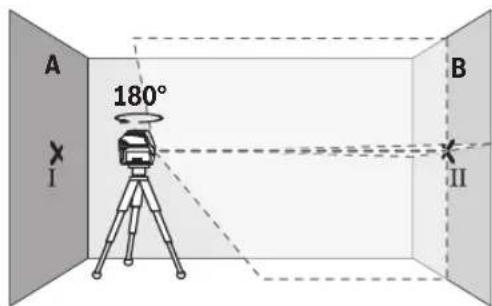
-3aBbpteteH3MepBaTeHHypeHa 180°,H3uKaaiTeTo Da ce HnBeInpa aBTOMaTHUHO n MapKnpaTe npeceHaTa TOka Ha DBeTe Na3epHN JINHH Bbpxy CTehata B (Touka II).
-IOCTaBeTe H3MepBaTeJIHHypeI -6e3 da ro Bbptnte -6Hn3o Do cTeHaTBA, BKJIOUte Ro I IO OCTaBeTe da ce HNBeHnpa.

-13mecTe H3mepBateHnH ypeD no BncoUHa (ype3 cTINBA INI pN Heo6xOIMOC T nOJaNAHe), Taka ye npceHuata TOCA HA Ia3epHIne Ibyn Da nona ToHOb BBpxy MapKnpaHATA npeDToBa ToKa II Ha CTenA tB.
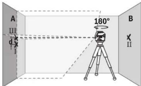
-3aBbptTe H3MepBaTeHnHa ypeHa 180°,6e3Ja npomeHnTe BnCOuHnHa.HacOeTe Ro KbM CTehAraTaka,Ye BEPTNkAlHATA Na3epHa HnHn Da npemHHaba npe3MapKnPaHATA npei TOBa TOka I.N3uKaaiTe H3MepBaTeHNrYpeDaa Ce HNBenpa Ha MapKnpaIte npeceHuTaTOka HA Na3epHHeNbHnHa CTehA(Touka III).
-PaJIHKATA d MEXdy DBete MapKpuHn TouKn I I I HA CTeHata A daBa DeICTBNTENHOTO OTKNOHeHne NO BNCOHNHa H3MEpBAteHNHy ypeD.
Ha pa3ctoHHe oT 2 × 5 m = 10 m MaKcImaJIHO DoIpyCTmoTO OTKIOHEHe e:
10m×±0,3mm/m=±3mm.CneIOBaTeHOpa3NIkaTa d Mekdy ToKHTe I N III Tpr6Ba da e HaH-MHOrO 3 mm.
PpOBepKa Ha ToUHOCTTa HA HMBENHpAne Ha XOpH3OHTaHATA MHHNA
3a npoBepkata ce Hxkaete ot Cbo6oHa nnoo ot npn6n. 5× 5m
-MoHTnpaIte H3MepeBaTeHnHny ypeD B cpeDaTa MeKdy CTeHNrte A N B Bbpyx CtaTnB HnI rO nocTaBe T bpyx 3dpaBa paBaHa oChOBa. N36epete pexm XOpN3OHTaIIHa IINHna C aBTOMaTHUHO HnBEnHpaHe HnBEnHpaTe H3MepeBaTeHnHny ypeD.

-MapknpaTe cpeTa Ha na3epHaTa nnHnHa nDbTe CteHN Ha pa3cToHne OT na3epHna ypeo 2,5 m (TouKa I Ha cTeHa A N TouKa II Ha cTeHa B).

-3aBbpteteN3MepBaTeHHypeHa 180°,noCTabeTe ro Ha pa3ctOAHne 5 m N3uKaaiTe da CE HnBeHnpa.
-ImecTe H3MepBaTeHnHrypeN NO BnCOuHa(Upe3 cTbBAHnPn Heo6xOHNMOcT CnoNaIaHe),takaue CpeData Ha Na3ePHN JbH da nonaHHe TOUHO BbpXy MapKnpaHata npedTOBa TOUkA II HA cTeHATA B.
-MapKnpaTe Ha cTeHaA CpeTaHa NaIa3epHaTaNHHN KaTo ToyKa III (TOUHO HAp, pecn. NoTouka I).
-Pa3nKata d MeKdy DBeTe MapKnpaHn TouKn I III Ha CteHata A daBa DeIeCTBnTEHOTo OKIOHeHne Ha N3MepBaTeHNHa ypeD OT BODopBAHATA nnHna.
Ha pa3ctOaHHe oT 2 × 5 m = 10 m MaKcHMaJIHO DOyCTHMoTO OTKIOHeHHe e:
10m×±0,3mm/m=±3mm.CnEoBATEHOpa3Nkata d meKdy TOOKTEI IITPRA6Ba da eHaM-MHOrO 3 mm.
PpOBepKa Ha ToHOCCTHa HnBEnHpAe BbB BePTKAnHO HanpaBHeHne
3a npOBepkata ce HxKdaeTe OTbOp Ha BpTa, npH KOrTO (Bbpxy TBbpda OCHOba) HMa Hau-MaNko No 2,5 m Cbo6oHa nloou OT DBete CTpaHn.
-NotabeteH3MepBaTeJIHHypeJHa pa3ctOHHne 2,5 m OTBopa Ha BpataHa TBbpda,paBH OCHOBa (He Ha CTaTb).N36peTe pexHM Ha BEptKHanHa IHHnC aBTOMaTHUHO HMBenPahe.HacoueTe Na3epHATAIHHN KBm Bpa
TaTaN3UaKaIte N3MePBATeHnHrTypeN da ce HnBeHnpa ABTOMATNo.
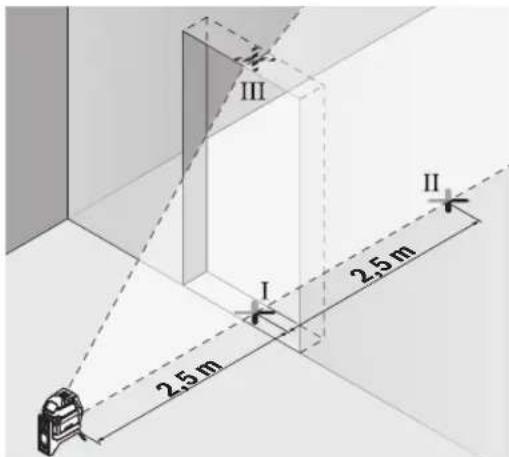
-MapknpaTe cpeTa Ha BepTKaHATA na3epHa HnHnHa noda Ha OTbopa Ha Bpata (Toka I), Ha pa3ctOHHe 5 m ot npyra TcpaHa Ha OTbopa Ha Bpata (Toka II), KaKTo n Ha roPHn pb Ha OTbopa Ha Bpata (Toka III).
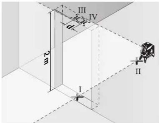
-3aBbpteteH3MepBaTeHNHa ypeHa 180° n ro noctabeTe OT dpyrata cTpaHa Ha OTbopa 3a Bpata HENocpeCTbeHO 3aTouka II. N3aKaAte H3MepBaTeHNHaT ype Da ce HINBeNIPA HACOyTe BepTKaKHaTa Na3ePha NInnra Taka, Ye CpeDATA N da MNHaBa Npe3 Touknte I n II.
- OtbenenkeTe cpeTata Ha naeepHata nHHnHa rOpHnpa6 Ha OTbopa 3a BpTa KaTo TouKa IV.
-Pa3nKkata d MEXky DBeTe MapKnpaHn TocKn III IV daBa DeNCTBHTeHOTO OTKIOHeHne NO BNCouHn Ha N3MepBaTeHHypei.
-ИзмеретьиоунотаHaOTbopaHaBpata.МakcmaHIOdonyctmOTOOTKIOHeHneMOXeTeJaI3uCnHTeNoCJIHNHaUHH:ДВaTINBICOCHHATAHaBpata × 0,3mm / m IpIMep:ПпВСOCHHаHaBpataOT2mMaKcmaHHTOOTKIOHeHneMOxeDa6bde
2× 2m× ± 0,3mm / m = ± 1,2mm CnepoBaTeHNO ToUKHe III IV moKe da ca ha pa3ctOaHne eoHa ot npyra HaMHoro 1,2 mm.
PpOBepka Ha ToHocTHa HoTBeca
3a npOBepkata ce HxkaeTe O CBO6OHa 30Ha 3a H3MePbAHe Bbpxy TBbpda OCHOBA c pa3cToHHe MeKdy NDoI Na TaBaHa npn6n.5m.
-MoHTnpaIteH3MepBaTeHNHa ypeKbMbBpTAAata ce CToiKa (23) nroNoCTaBeTe Ha nOda. N36epeTe TouKOB peKIMn 3uKaaiTe aBTOMaTHHOTo HNBenpaHe Ha n3-MepBaTeHNHa ypeI.

-MapKnpaTe ceHbpa Ha rohpata naeepHa Touka Ha TabaHa (Touka I).MapKnpaTe cBIO taka Ha nOda ceHbpa Ha DOnHaTa naeepHa Touka (Touka II).

-3aBbpteteH3MepBaTeHHypeHa 180°.No3uOnOHpaIe ro taKa,ye CEHTbpbT Ha doJHATA na3epHa TOka da e ToUHO Bbpxy MapKpHaHaTa TOka II. H3aKaIte ABToMaTHuHOTo HnBeJIHpAHe HA H3MepBaTeHHypeI. MapKpaIte ceHTbpa Ha rOpHata na3epHa TOka (TOka III).
-Pa3nHKATA d MEXky DBeTe MapKnpaHn TOckn I n III Ha TaBaHa DaBa DeIcTBNTeHOTO OTKnOHeHne NO BICOCHHa HaN3MepBaTeHNHrype.
MaKcIMaJIHO DOIpyCTMOTO OTKIOHeHHe MoXeTe Da H3UcNITe NO CnEDHHaHnH:
IBOHHTO pa3CToHHe MeJy Nda H TaBaHa × 0,7mm / m IpHMEp:Pi npa3CToHHe MeJy Nda H TaBaHa ot 5 m MaK-CHMJIHO TO KIOHEHeMoKe Da 6bDe
2× 5m× ± 0,7mm / m = ± 7mm .CneIOBATEHOTOUKHTI n III moKe Da ca Ha pa3ctoHHe eHa ot Dpyra Hau-MHOrO 7 mm.
Yka3aHn 3a pa60Ta
BnHaHm Mapkpapte cehbpa Ha na3epHata toka, pecn. Ha na3epHata NHHa. C pa3ctoHHeTO roJeMNHaTa Ha Na3epHata ToKa, pecn. Ha na3epHata NHHa ce npomehra.
M3MePBATeHNNrTypee cBopbXeHc6e3KmUeHN HnTepfeic.Tp86BaJa ce cna3BaTeBEHTyAnHOrpaHnueHnHaNP.BcAMoNETnn60nHn.
Pa6ota c na3ephata MepuTeHa nNoouka
Ja3epHaMaepntHa nOua(31)noOpBbBA BnHmocTtHa na3epHnIb4 npH He6naRopnRTn pa60THyycNOBnNo-ronMpa3cTOnHH.
Otpa3Baata NOBbpxHocT Ha Ia3epHaTa MEPHTenHa nloa (31) NODo6pBa BVINMOCTT Ha Ia3epHaTa IHHN, a npE3 np03paHATA NOBbpxHOCT Ia3epHaTa IHHN MOKe da ce BnH IObpaTHa CTpaHa Ha Ia3epHaTa MEPHTenHa nloa.
Pa6oTa cbc cTaNb (npHnAdnEeXHoCt)
H3NON3BaHETO HA cTaN BOCnrypRa Cb6nHNO, perynpyeMo NIO BnCOUHNa MOHTnpAHe Ha H3MepBATEHHNya ypeI. NocTabeTe H3MepBATEHHNya ypeI c 1/4" NOCTABKATA 3a cTaNIB (18) BBpxy npncBeHNHTENHNA BNT HA cTaNBA (32) HnHa o6nKHOBE TPNHOKNK 3a fOtoanapat. 3aterHete H3MepBATEHHNya ypeI c BNHTa HA cTaNBA.
Ipei Da BkIOHHTe H3MePbATEIHnYpei, HAcOHTe CTAHBa rpy60.
MOnTHnpaHc yHHBepcaHnHaTcToHka (npHHaJIeXHoCT) (BHXTe pHr.L)
C nOMOuTa Ha yHnBepCaIHaTc TcOka (26) MoKTe Da 3axBaAaTe H3MePbATEHnna YpeD Hanp. KbM BepTnKaIIHn NOBbpXHOCTN, TpbHnHnHaMarHeTnIpaUnc Ce MaTePhaIh. YHnBepCaIIHATA CToHkA e NIOxOJaIcaCbIo Taka I 3a NoCTabReHa NpOa HOBKeUba HAcTpoBaNHeTO NBOCuOHHa Ha N3-MepBaTeHNHa YpeD.
H3paBHeTe yHnBepCaHaTcStoKa (26) rpy6o, npedn da BKNIOHTe H3MePBATeHNy ype.
Pa6oTa cna3epen npneMHNK (npHHaDnEeKHOCT) (BxKTe pHr. L)
3a no-d6po ha6nIoDaBaHe Ha na3epHna ly npn He6laonPnTHn CBETnHHn ycNoBn (CBETNa Cpea, HenocpeCTBeHn CbHuEBn lyu) Hn rOeMn pa3ctOHaNcpeopbYBaH3no13BaHe Ha na3epHna pnpemHnK (29).Pi npa60tn c na3epen npneMHNK BkIOUyBaTe peXm HA npemHnK (BX. "Pekm C npemHnK", Ctpanua 241).
OuHnla 3a Ha6bIoudaBaHe Ha Na3epHnIbU (npHaadNexKHOCT)
OuHnata 3a HabnoDaBaHe Ha na3epHHnIbUy fHnTpnpaT OKoHnTa CBeTIHa. Taka Na3epHHnIbUcCTaBnNo-NechOp a3NJHm.
He 3nON3BaHTe Na3epHNTe Ounna (npHaNDIeKHOCT) KATO 3aunTHN OUnna. Na3epHNTe Ounna cnyXat 3a noD6po pa3no3HaBaHe Ha Na3epHnra IbU; Te He npedna3Bat OT Na3epHo IbueHne.
He n3non3BaIte na3epHnTe ouHna (npHaadJeXhoCT) KATO cIbHcEBn OUYHa Hn npuwoHpaHe. Na3epHnTe ouHa He npedlarat PbHa UV 3aunHa n HamanBat Bb3pHnMaHTo Ha CBETOBete.
Pa60TH Hnphmepn (BHXTe fHr.G-M)
PpHmepn 3a npHNOKeHHeTo Ha H3MepBaTeHHypeN MoKeTe Da BnHTe Ha CTpaHncaTa C cnHyprte.
PoiDbpxaHe n cepBn3
Iopdbpxhae n nouchTahe
IopdbpxkaTe n3mepBaTeHHypeD BnHaHn uCT.
He notonBaTe n3MepBateHnry ypeD BbB BOda nn npyTteuHOCTN.
N36bpcBaIte 3aMbpcBaHnIa T MeKa,NeKo HbNaJxHeHa Kbpna. He n3noJI3BaIte NoUcTBAuI npenapTu nn pa3T BOpHTenn.
IouncBaTe peoBHO CneuaHNO NOBbPxHOCTte Ha 3xoDaHa na3epnHbU HBMaBaTe Da He ocTaBt BNaCnHKn.
KIneHTcKa CnyX6a H KOHcyNTaCn OTHoCHO yNoTpe6ata
CepBn3bT 0e OTROBOpHa Bbnpocite Bn OTHOCHOpeMOHTn I NOpDpbKka Ha 3akyPeHnO T Bac npOyKT, KaKTo N OTHOCHO pe3epBHN qactN. POKOMNoHEHTH NeuTeKx N HΦopMaZIa 3a pe3epBHNte qactN 0eOTKPneTe H a:
www.bosch-pt.com
EknnbT no KOHcyntaun OTHOCO yNtpe6ata Ha Bosch ue Bn NOMORHe C yIOBOJCTBNE npn Bbnpocn 3a HauHTe npoDyKTIn TExhNTe akcecoapn.
MOnI, npn Bbnpocn H npn npbpyBahe Ha pe3epBHN qacTH BHHaHn nocOuBaHte 10-uaPpeHn KaTaoXKeH Homep, H3NHCan Ha Tabekata Ha ypea.
Былария
Robert Bosch SRL
Service scule electrice
Strada Horia Macelariu Nr. 30-34, sector 1
013937 Bucuresti, Romania
Te.n.: +359(0)700 13667 (Блгарский)
a c + 40212331313
Email: BoschServiceCenterBG@ro.bosch.com
www.bosch-pt.com/bg/bg/
DpyrH cepBn3HH aIpeCh uie oTKpHeTe Ha:
www.bosch-pt.com/serviceaddresses
TpaHcnpOpTnpaH e
IpenopbunTeHNHTeNTHeBO-HOHHaKymyataOpHb6atePHn Tpa6BaJa H3NbHnBaT H3NcKBaHn 3a TpaHCnOpTpHa Ha onacnTOBapn. AkymyataOpHnTe 6atePHn Moat Da 6bDat TpaHCnOpTpHaHOTpe6ntenHa Ny6nHm MecTa 6ez DOnbHnTeHN pa3peuHTeHN.
Ipn TpaHcnpTnpaHe OT TpeTn CtpaHn (Hanp. npn Bb3dyweh TpaHCnopt Hnn NOn3BaHe Ha KypnepcKy ycLyH) HMa CneuAnHn H3NCKBaHn KbM ONaKOBaHEo O6O3NaUaBaHTo IM.
3a ceta npn noTROBkata Ha naKeTnpaHTo Ce KOHCyItnpaIte C eKcnept B cbOTBeTHata ObnaCT.
H3npaataeakymnatoptnh6atepnncam0akoKopnycbt Hne nOBpehen.H3oInpaTe OTkPHTN KOHTAKTHN KJIEMC neIaHnIeHTN ONAKObaTe akymnatoptnh6atepnntaka,ue da He MoRaT Da Ce H3MeCTBaT B ONAKObKaTa Cn. Monr,
CnA3BaIe CbIoo HOnbJIHHTeHN HaIIOHaJIH NpeDIncaHH.
Бракуван

C orneoanaBae Ha oKoHnHa Tcpea H3MepBaTeHHy ypei,OBKnHOBeHNTE uN akyMnaTOpHNbAtePHN,doNbHnTeHNTE pNnHaJNeK-HocTHn OAnokOBKe Tp8BaJa ce npedabat 3aONo3OTBopBAHe Ha cbbpkaunte CE TBX
CypOBHHN.
He 3XbpynIe H3MepBaTeHnTe ypeNi n akymyataopHnTe 6aTePN/6aTePNTe npN 6ntoBnTe OTnabu!
Cama 3a CtpaHn ot EC:
CbINaCHO eBpOeNcKa dIpeKTHBa 2012/19/EC 3a cIapHTe eIeKTPnueckn n eIeKTPoHn ypei n HeHTo TpaHCnpTpaHe B HAIOHOANHO TPABO H3MepBaTeHNtE ypei, KOHTo He Morat da ce non3BaT nobYe, a CbINaCHO eBpOeNcKa dIpeKTHBa 2006/66/EO nobPeHn Hn H3xa6EHn O6HKOBen Hnn akymyntopn Hs BateHH, TprBa da ce cb6upat n npedabat 3a onol3OTBOPBAhe Ha cbdbpxaunte CE TBx cyPOBHH.
PnHnepaBnHIO n3XbBpIaHcTapIte eneKtpuueckn H eNEKTPoHHN ypeiN npaDN Bb3MOxHOTo HaJIuYe Ha ONaCHN BeUeCTBa MOraT Da OKaKaT BpeHN BInraHn BbpxO KOnHaTa Cpea N OOBeWKTo 3dpaBe.
Akymnyatopn6atepn/6atepn:
JIITHEBO-NOHHN:
Mon, cna3BaTe yka3aHnraB pa3dena TpaHcnpTnpahe (Bx. ,TpaHcnpTnpahe", CtpaHnca 246).
MaKeDoHcKn
Be36eHocnHaNoMeHH

Ctye ynatcbTa Tpe6a Da ce npoHTaT n da ce BHHMABA HnHb, 3a Da MoKe 6e36eHNO 6e3 onaCHO Ta paBoITte Co mepHnotypei. DOKONky MepHnotypeI He ce
KOpHCTN corIacHO npHIOXeHHTe HnCTpyKunH, MoKe da ce HApUH ΦyHKunJaTa Ha BrpaJeHTe 3aWtHTn MExAH3MH BO MePHNO TyeJ. He rOwTeTyBaJte HaneHNuHTe 3a npeDynpeDuBaHe. IOBPO UYBAJTE rOBNE YIATCTBA N PPEDADETEN 3AEDHOC MOPHNO TyeJ.
BHHMaHHe -DOKKky KOpHCTNe Dpyr Hyei3a NOdecyBaBe HpaKyBaBe OCBeH OBDe HabeJeHHTe NIN NONHaKNB NoCTaIKN, OBA MOKe Da DOBeE Do ONaCHA H3IOKeHoCT Ha 3paueHe.
MepHnOTypeCeHCnpaUyBaCo03HaKa3a npEynpeyBaBe 3aIacepot(O3HaueHoHaIIpHKa3OT Ha MEPHNOTypeHa rpaΦnKATAcTpHa).
Dokonky TeKcTHa 03HaKaTa 3a npEynpEyBaHe 3a nacepot He e Ha BaHnot ja3NK, Bp3 Hero 3anenete ja HanenHHncaTa Ha BaHnot ja3NK npE npBata ynorpe6a.
He ro hacouybajte Iacepcknot 3pak KOH Hnua HnN XnBOTH N HEmoJte H Bne camnte Da rIeDte BO dHpeKTHNOT Hn pePektnpauchknot nacepckn 3pak. Taka
MOKe Da rH 3acneHnTe NnUaTa, Da npEni3BnKate HecpeKn nN da rH OWTeNTe OHTe.
Dokonky nacepcknot 3paK Docnee do ouHTe, BeHaaw Tpe6a da rH 3aTBOPHe H da ja TprHete rnaBata oN nacepcknot 3paK.
He npabete npomenn Ha nacepcknotype.
He hKopnctTe Iacepcknte 3aHTTHOn Ouyna (DONONHTENHa ONPema) KAKO 3aHTTHOn OUYNA. Iacepcknte 3aHTTHOn Ouyna cnjykat 3a noD6po pacno3HaBaHBe Ha IacepckNt 3paK; cenaK, Tne He WHTAT OD IacepCKTO 3paueHe.
He Hn Kopnctete Nacepcknte 3aunTHn OuHa (DOnonHHTenHa onpema) KaKo OuaHa 3a coHcE Hn nak Bo coo6pakajot. Nacepcknte OuyHa He daBaat cenocha UV-3aHTHa Ito HaMaNyBaat npenosHaBaeTo Ha 60n.
MepHnotypedcmee da ce nonpaba camo od ctpaHa KaBnHnKyuBaH CTpyeH nepcoHan Cama co OPHnHaHN Pe3epBN DenOBn.Camo HToJ hauHH Ke 6ndete cnryphn BO 6e36ednocta Ha MEPHnotypeid.
He n octabaje da ra koHCTat nacepcknot Mepeh ypei 6e3 hao3op. Be3 hao3op, Tne moKe da ce 3acnenat ce6ecn nn npyri niua.
He pa6oTe co MepHnOypeB OBO OKOnnHa Kaede NoctOn OnaCHOCT OekCnNo3nJa, Kaede NMa 3anaNHB TeHOCTH, rac HIN npaunHa. MepHnO ypeD co3DaBa NCKPN, KOH MOKe Ja ja 3anaNat npaBA Tn nna naeata.
He ja orbopajte 6atepnjata. nocton onaCHOCT OJ kpatok cnoj.
PnH OHTeYBaBe HENPONHcHa yNtpe6a Ha 6aTepnjata MoKe Da H3ne3e Napea. Batepnjata MoKe Da ce 3aannn Hn Da ekCnNoHa. BHece T CBex BO3dyx H DOKoKny HMa IOBpeEHN OHHeCeTc Hn HaNekap. Papeata MoKe Da Hn Hndpa3Hn DnHInte NaTHta.
Pn norpeuho Kophebe Hn npohwTeHa 6atepnja moke da hcteue 3anaHb aTeHoCT od 6atepnjata.136erhybaje KOtAKT co Hea.10kONky Cnyauhdojde BO KOHTAKT CO TeUHOCTA, HCnnaKHeTe Co Bda.10kONky TeHocTa JoJe BO KOHTAKT Co OHTe, no6apajte NekapcKa NOMoi. IcTeeuHaTeHoCT od 6atepnjata Moke da npedn3Bnka KOKHN npHTaunnnn Hn H3ropeHHn.
Batepnjata Moke da ce owtetn od octpnte npedmetn KaKo Ha np. Knnncn HnN OdbpyBaHnH co Hnbopeuho BnnaJne. MoKe Da doJe Do BHaTpeWeH Kpatok cnoj n Batepnjata Moke da ce 3anaH, da nyuTuH aD, da ekcnnoipa nn da ce nperee.
Heynotpe6eHata 6atepna dpKte ja noaneky od KaHcIapnckn cnojybalkn, KnyeBn,Keene3nn napn, KInHn, 3aBPKN HnDpyrMaH MeTaNn PnpMeTH, ITO MOKe Da npEn3BnKaat npeMoCTyBaHe Ha KOHTAKTHe. KpaTOK cnoj meY koTakTHe Ha 6atepnjata MOKe Da npEn3BnKa HropeHn nnIOkap.
Kopctete ja 6atepnjata cmo BO npOn3B0nO npOn3BOOnTeNo. Cmo Ha ToJ HauHH 6atepnjata Ke ce 3aHTTN OJ onaCHO npeontOBapyBaHe.
Баерпente nonheTe rco nonhaun wTo ce npenopaahn HcknyuHBO od npoh3BOHTeNoT. ДOKONky nonHaOT 3a KoJ ce HameHeTH OndpeDen BnD Ha 6aTeHH, ce KOpHCTn coДpyn 6aTeHH, noCTOn onachOCT od noXkap.

3aHTTe ja 6atepjuata od tonnHa,Ha np. od DonroTpajno H3NOxyBaBe Ha COHueBn 3paun, oran, HeuHCTOnH, BODa H Blara. nHaky, nocto onaCHOCT od ekcnnoJna i Kpatok cnoj.

He npnhecybaTe MePNOT ypeH marrhenata onpema BO 6n3nHa Hmnnantn Hn DpyrMeHNuHcKn ypeH,Ha np. nejcmjeepn Hn Hncynncka nymna. Ipeky MarheTte Ha MEPHOT ypeH n onpemata ce pno3BeyBa None, KOeIto MOKe da ja Hapyu PhyHKuJaTa Ha HmPnAHTte Hn MeDnHCKNTe ypeH.
Држete rH MEPHnot ypeH mARHeTHata onpema nOdaNeky OJ MaRHeTHn HocauHa NoDAtoUH ypeH uYBCTBHTENn Ha MarHeT. IopaIN BnJaHNeTo Ha MaRHeTte OJ MEPHnot ypeH nOpemTa MoKe JaDojde Do HEnOBpaTHn 3ary6n Ha NoDAtoUInTe.
PepKaKb6HNO HHTepBHeuJa Ha MePHHot ypeI (Ha np. MoTaxKa, ODPxkyBaBe nTH.) KaKO Hn PnH HerOB TpaHCnOPT N ODPxkyBaBe H3BaTe To akyMnyaTopoT oH. 6aTePNTE Od MePHHot ypeI. Pn HeBHnMaTeHnHO pNtncKaHe Ha IpeKNHyBaQTo 3a BkNyUyBaBe/ NCKNyUyBaBe NoCTOn OnaCHOCT OJ NOBpei.
BnmaHne!PnKopHeBeToHaMepHnotypeCo BluetoothMOKeJaHactaHATPpeKnHaDpyrHte ypeHnCnCTeMH,ABHOHNMeDnHcKnAnapatn(Ha np. nejCmeJkep, anapatuHb3a CnyuBaE).NcToTaKa He MoKe zenocHo Da CE NCKyUH moXHoCTa 3a NOpeHa NaYre HxNBOTHBO HeNoCpeHa OKoHnHa. He ro KopHeTe MEPHnotypeCoBluetooth BO 6nHnHa Ha MeDnHcKn ypeH, 6eHnHckn Pymn, Xemnckn ypeH, 6nactn Co onacnoct Oeknno3na H Bo 6nHnHa Ha MHHcKn NoHbA. He ro KopHeTe MEPHnotypeCoBluetooth BO aBHOHN.36erHybaJte DOnroTpajHa yNoTpe6a Bo DnpeKTHa 6nHnHa Ha TeNoTO.
O3HaKaTa co 36OpOBu Bluteoth KaKo n CnKNKeTne (Noroata) ce perHcTPhaHm MapKn H conCTBeHoCT Ha Bluetooth SIG, Inc. Cekoe KopncTeHe ha OBaa O3HaKa co 36OpOBu/cnKn Ce BpuH co NueHca npEky Robert Bosch Power Tools GmbH.
OnncHa npoH3B0DoT nepopmaHCnTe
BHHMaBaJTe Ha cIHKnTe BO npeHnO T dE Ha yNaTcTBOTa KOpNCteHe.
YnOte6a co cooDbetHa HameHa
MepHnoT ypeI e HameHET 3a OndpeyBaHe I npOBepKa Ha XOpHIOHTaIIH N BepTKaIIH IIHH, KaKO H TOKHa BepTKaIaNtA.
Mepnnotypee noroedentka Kopnctebe BO BhatpeuHn HndBopeuH npocstop.
Co nomow ha potaohnoHOT dpkaR 2 moKTe da ro BPTNTe MEPnHOType360°okony ceHTpaHaTa H cekoraw BnHBATA TOKa Ha BepTKanata. Co toa TouHO ce ycornacyBaat Nacepckte Hnnn, 6e3 da ja npomeHite no3njuTah aHa MEPnHOType.
Hnyctpaunja ha komnoheHTN
HymepnpaBeTo Ha cInKHe Co KOMNoHeHTn Ce OndecyBaHa npka30Ha MePHNtypeHa rpaФuKaTcStpAnua.
(1)BoJeUKNKJIe6
(2)П配电ИнБачзВКлуваьe/ИСКлуваьe
(3) ΜηεηθΟβρο 3a nαερκησιθερα
(4) Coctoj6a Ha HanoHETOCT Ha akymyNaTOPCKNTE 6atePN/6atePNNTE
(5)Пикадocиларогаблokада
(6) KonquepeXHM Ha npneMHNK
(7)Ппказpeжимнапрсemнн.
(8) Konue 3a nacepcknT BnHa pa60Ta
(9)Пиказа врсампекуBluetooth®
(10) Konque Bluetooth®
(11)перрада за батерида.
(12) BaTepuJa
(13) 06BnBkaHa6aTepeNCKnot aadantTepa
(14) BaTepeHnna
(15) Konue 3a ocno6ooyBaHbe Ha akyMnyatopckata 6aTePnJa/6aTePncKnOT aanTep
(16) Kanaye 3a 3atbopahe Ha 6aTepecknot aadantepa
(17) Hattnc 3a npdynpdybahe Ha nacepot
(18) Pnphat Ha ctaTHOB 1/4"
(19) Cepnckn 6poj
(20) Ⅲин ha BoDnKka
(21) MarHet
(22) Идолжень OТВОРи 3a пицВрстУВаьe ^a)
(23) PoTaunOHeN dPkaay
(24) 3aBPTka 3aФINHO NODECyBaHbHe Ha potaunOHnT DpxKaay
(25)TabaHcKa cTeRa
(26) yHnBep3aene npxka
(27) BpTnBa nlaTΦopMa
(28)Далецнску npaВаua
(29) Nacepckn npneMHNK
(30) Nacepckn 3aunTHnOuHa
(31) Nacepcka uehna Ta6bna
(32) CTAHB
(33) Teneckoncka npaKa
(34) 3aunTHa aHa
(35) BaTePnCKn aIaNTeP
(36) KyΦeρ³
a) NHyctpnaHATA HnONnHnHaONPema He e den od CTaNapdHnOt OeMa HAHCnopaka. CEnoCHata ONPema MoKe Da ja hajTe Bo Hauata Pporpama 3a ONPema.
Texnukn noDaToun
HanomeHa: KopHeTeHo Ha 6aTeepn KOn He Ce COoBETHn 3a BaHOT MepeH ypeD MoKe Da DObeDe Do NOrpeH0 fHKUHOHPaBe HnDo OWTeTYBaBe Ha HCTNOT.
Hanomeha:Batepnjata ce ncnopauyba denymho HanonHeta.3a da ja HanonHnnte eNocho 6atepnjata, nped npBaTa ynoTpe6a ctabete ja ha nonNau doKeHa ce HanonHn nuocho.
Hym-johcknte 6atepn Moke da ce HANonHb CeKoe BpeMe,63 da ce HAMn HBNHT KINBOTeH BEK. PpeKNHot npnONHeBTo He HaHTyBa Ha 6atepnjata.
Hym-johckata 6atepnae3auntheo od napokopnapehbe co „Electronic Cell Protection (ECP)"doKony6atepnjata encnpa3eta, mepnoT ypece ncknyyba co3aHTEN peknhybay.
He ro Bknybajte MeHHOT ypeI oHBO, OTKako Ke ce NcknyuO od CTpaHa Ha ChryphocHTO KONo.
Batepnjata moke da ce owtetn.
3aBMETHyBaHe Ha HanoHeta 6atepnja (12) BMeHTe ja BO OTBOPOT 3a 6atepn (11), ce doNeKa He cnuyHete da ce BKJOnn.
3aBaBeHe Ha 6atepniata (12) npntnche Ha konHbata 3a OTKnyBaBe (15) n H3BneTe ja od OTBOPOT (11).
Pntoa He ynoTe6yBaJte cna.
Pa6ota co 6aTePnn
3a pa6oTa co MePHNt ypeI ce npenopauyBa KOpHCTe H aKanHO-MaHraHcKn 6aTePN.
BaTePmIte ce cTbAaT Bo 6aTePnCKnOt aanTep.
Batepncnoa ananep e HameHt NcknyuHBO 3a npedbndehnte MePHn ypeHn Ha Bosch H He cmee da ce Kopnctn co enektpnuHn anatn.
3aBMETHyBaHe Ha 6aTePnHTe CTaBeTe ja 06BnBkata (13) Ha 6aTePnCKnT aanTep BO OTBOPOT 3a 6aTePnn (11).
CTabete r6batepHnTe cnopei cnKata Ha Kaanayeto 3a 3aTbopahe (16) BOOBVBkata. CTabete ro kanaeTo 3a 3aTbopahe HAD OBVBkata,doKeHa ce CnyuHete Da Ce BKIOH.

3a BaHe Ha 6aTePnHTe (14) npTnCHeTe Ha KOnuHbTa 3a OTKnyBaBe (15) Ha KaNaeTo 3a 3aTbOpaHe (16) nOBLeYeTe ro. PnHToa BHMaBajTe Ha He nCnAdHat 6aTePnHTe. DpKeTe Ro MEPnOtypeD co OTbOpOT a
6aTePNH (11) Hacouen Harope. N3BaTeTe rN 6aTePNHTe. 3a da ja N3BaJNTe O6BnBkata (13) 0B BnATpeuHocTa oD OTBOPOT 3a 6aTePNH, fate TE ja N3Bneye TE ja co NecHO npTHCKaBe Ha CTpaHHHNO TSD ON MePHNOT ypeI.
Cekoraw 3amehybajte rncnte 6atepnn OednaW. Kopnctete camo 6atepnn o eden npoh3bOaHTEN CO nCT kanaTET.
Ako He ro KopnCTHe MEPnHOType nOOnrBOpeMe, n3BaTe r6bATEpHNTe. Pn noOnro cKnAnpaBe BO MEPnHOType,6aTEpHNTe MoKe da KopoOnpaat Ha ce Hcnpa3HaT.
Pmka3 Ha cocto6ata Ha HANONHETOCT
PnPKa3OT Ha COcto6bata Ha HAnONHeTOcT (4) HA ekpaHOT ja nOKaKyBa CoCTO6bata Ha HAnONHeTOcT Ha AkyMylaTOPOT ODH. 6aTepeNITE:
LED-cBETMNK Cocto6a Ha HanoHHeTOCT
Tpajno3eJeNo CBeTNO 100-75%
TpaJHOXoIToCBETNo75-35%
TpeKkaBOUpBeHo <35% CBETNO
HemaCBETNo-DepeKTHa batepnja
-ПраЗнбастерни
AkoakymyataPOPOTOnH.6aTePHnTEocna6byBaT,CbETIOCTa HaIacepCKNTeHHN NoneKa ce HamaNyBa.
Bedha3aemeHete ro HeCnpabHnot akymyNatop nI npa3nnte 6ateHH.
Pa6oTebe co potaunohnoT npkau RM 2 (BnDn CnKn A1-A3)
Co nomow Ha potaunohnoT dpkau (23) moxete da ro BPTnTe MEPHNO TyeD OKOly ueHTpanHaTa H cekoraW BnBnBaTo4Ka Ha BPtNkAnata 3a 360^ . Co Toa ce NoCTabyBaat Nacepcknte nnHH, 6e3 da ja npomeHnTe No3nJaTa Ha MEPHNO TyeD.
Co 3aBpTkata 3aФHNO IOdecyBahe (24) MoXeTe Da yCOrnACHTe BepTKaJIH NacepCKN INHHIN TOHHO pepepeHTHNTe TOKNI.
IocTaBete ro MEPHnot ypeD co BOdeuKnot Kne6 (1) ha
UHaTb BOHNka (20) Ha potaunOHnot dpKaue (23) H
PnTHcHete ro MEPHnot ypeD io KpaJ Ha nnaTOpMaTA.
3a da ro n3BaNITE, n3BneueTe ro MEPHnot ypeD BO o6pateH
npabeU od potaunOHnot dpKaU.
Mozhnoctn 3a no3nOHHpaBe Ha poTaONHOHT dpKau:
-BOHCnpaBeHaNoIoo6Ha paMaHa nobPunHa,
- npnucpcTeH Ha BepTikalHa nobpunHa,
-NOBp3aHa cO TaBaHcKa cTera (25) Ha MeTaJIHn TaBaHcKn JajCHN,
- CO NOMOOW Ha MaHET (21) HA MetaJIHN IOBpUHHN.
Ynotpe6a
CtabaBeBoynotpe6a
3aHTTeTo MepHnOTypeoBnara HnHpeKTHO HNOxyBaBe Ha COHcEBN 3paun.
He ro n3loxybaJte MEPnHOT ypeHa ekctpemn HTEMnepaTyPi Hn TEMnpaTyPHN Ocunnau. Ha np. He ro octabajTe doIro BpeMe BO ABTomObnot. Pn Hrlemn TEMnepaTyPi Ocunnau, OCTabete Ro MEPnHOT
yped npBO da ceakimmatnnpa HnpaBete npOBepka 3a ToHocTa cekoraa nped da npoDOnKHe co pa6ota (BnuN, KoHTpona Ha ToHocTa Ha MePHNoT ypeD, CtpaHnca 253).
PnEeKCTpeMHN TeMnepaTyPi NIN TeMnpaTyPhN OCuHaauH, Pneun3HocTa Ha MepHnotypeMDoKe da ce HApuyi.
136erhybaje yapn n npebpybaba Ha MePHNOType. IIO CINHN HADBPOeHH BnJaHJaHa MePHNOType, nped da ro ynotpe6nte 3a paobota, cekoraWn3BPwETe KOHTPOna Ha ToHocTa (BnD, KoHTPOna Ha ToHocTa Ha MePHNOType, CtpaHnca 253).
NcknyeTe ro MEPHnOType3a BpeMe Ha TpaHCnoptOT. Pn HCKnyuBaHbeto, ce 6noKnpa ocunlnpaKaTa eHNHa, KoJa 6n ce oHTeTnna npn INTEH3NBn DBHXKeBa.
BknyyBaBe/ncknyyBaBe
3a BknyBaHe Ha MEPnHOType npHTCHeTe ro npeKHyBaOT 3a BknyBaBe/HckNyBaBe (2) BO no3nJaOn (3a pa6oteBe co ocunatopHa 6nokada) Hn BO no3nJaOn (3a pa6oteBe co aBtOMaTHka 3a HnBeInpaHe). BeNaH No BknyBaHeTo, MEPnOType nyTa NacepCKn nnHnOd Hne3HnTe OTbOpN (3).
He ro hacouybajte 3pakot CBETnHa KOH nHa Ka Hnn KHBOTn H He NorneHyBaJte DnpeKTHO BO Hero,dypn HN od ronema ondaneheocct.
3a ncknyyBaBe Ha MEPnHOT ypeI npTnCHete ro npeKHyBaOT 3a BknyyBaBe/ncKyUyBaHe (2) BO no3nJa Off. Pn HcknyyBaBe, ocunnpaKaTa eHNHa ce 6nKnpa.
He ro ocTabaje BKNyueHnO Mepeh ypeI 6e3 Hau3Op ncknyute ro no ynotpe6ata. pyrnte Iua MoKe da ce 3aclenat OJ NacepcknOT 3paK.
Пин НадMinHyBaHe Ha HajBICOKaTe Do3BOJeHa pa6OTha TempepaTpa od 50°C ce nCKnyuBa 3apAn 3aHTTa Ha nacepckata DnOda. OTKako Ke ce onaDi, MEPHnot ypeI e NOBtropHo NpOrTBeh 3a pa6To n Moke oNHOBo Da ce Bknyu.
ABTomathkaHaNcknyyBaBe
Iokony 120 min He ce npnnche HneHNO konue Ha MePNOT ype, ToJ ce ncknyBa ABtOMatcKn 3apadn 3aHTHa Akymnatopckte BatepOn OH. BatepInTe.
3a da ro BKnyuHTe MEPHnOT ypeB BeHaA IO aBTOMaTCKOTO NCKnyuBaHe, MOKeTe HnH HajnpBO Da rO npTHcHETe IpeKHyBaOT 3a BKnyuBaHe/NCkNyUbHe (2) BO nO3nJua .Off' nTOa NOBtOpHO da ro BKnyuHTe MEPHnOT ypeI, INI da npTHcHETe Ha KOnyeto 3a peXmH pa6ota Ha Naacepot (8).
DeakTNBnpaBe Ha aBTOMaTHKaTa 3a NCKIyUyBaBe
3a da ja deakTNBnpate abTomatNkata 3a ncknyuBahe, dpjke ro npntncato konyeto 3a pekmHa pa6ota8 (npn BknyeH mepeh yepi) hajmaKy 3s. Dokonky abTomatNkata 3a ncknyuBahe e deakTNBnpaHa, nacepcknte 3paun KpaTko TpenKaat 3a notbpda.
Hanomeha: Ako pa6oTHata TemnepaTypa ja HaIMHHyBa 45°C, aBtOMaTHKaTa 3a NCKNpyBaHe He MoKe da ce deaKTbnpa.
3a da ro akTNBnPaTe ABOMaTcKToTo HCKnyuBaHe, HCKnyeTe ro MEPHnotypeI NOBTOHO BKnyeTe ro.
NoecyBaHe Ha peKHMOT Ha pa6ota
MepnnoT ypeI hma NobeKe hauHH Ha pa6ota, KOH MOnKe da Tn IpomEnHe BO 6HIO Koe Bpeme:
-PeKHM HbBkpcTeHnHHHnToUKeCTpeKHM: MepHnotypeI npOn3BvBaXOpH3oHTaHa N BeptNKaHaNacepKa nHaJaHaHaNPed, KaOi BeptNKaHa NacepKa ToKa HaRope HADony. NacepckTe HnHHcBe BkpcTyBaAT noJ aron 90°
-XOpH3OHTaEN HINNcKn peXHM: MepHNoTypeI npOn3BeyBa XOpH3OHTaHa nacepcka HINHJa HAHanpei.
Pa6oTeHe co aBTOMaTHKa 3a HHBENHpAbe
-BeptnKaJIeH nHHckn peKIM: MepHnot ypeI npOn3BcYBa BePTnKaIIHa Iacepcka IIHHJa HaaHpeI. Ppi N03uONHpaIbe Ha MEPHnot ypeI BO coba, BePTnKaIIHaT aIacepcka IIHHJa Ke IokaJyBa Ha TaBaHOT HAD rOpHATA Iacepcka IIHHJa. Ppi N03uONHpaIbe Ha MEPHnot ypeI dIpeKTHO Ha sIa, BePTnKaIIHaT aIacepcka IIHHJa IpoN3BcYBa peHCn cIeIOChA KpyKHa Iacepcka IIHHJa (360^ -nnHja).
-Tockct pexHM: MepHnOtypeI npOn3BeyBa BepTKaJIHa nacepKa TOUka Harope HnHOJy. CHTe HauHH Ha paBoTa MoKe Ja ce H36epaT co ABTomAtKa 3a HnBeHnpaBe KaKo N CO OcunNaToPHa 6nOkada,OCBeH ToCHCTNt PEXHM.
3a da ro cmeHnte haunhot Ha pa6ota, npntnche Ha konueTo 3a peKmHa pa6ota Ha nacepot (8).
| Рedingлесд на чекорientsа равotas Хорозанале н линникpenхим | Вертыkanени линникpenхим | Точность реким | Прinksа ocumnatорна бл_OKада (5) | Слика |
| Прешинывача вklуваиь/ нсклычнываче (2) bo поцида, n" | ● ● ● | B | ||
| Реким на Вкрстен линners | ||||
| Laser Laser Laser Laser Laser Laser Laser Laser Laser Laser Laser Laser Laser Laser Laser Laser Laser Laser Laser Laser Laser Laser Laser Laser Laser Laser Laser Laser Laser Laser Laser Laser Laser Laser 4×прешинываче на чекero за рекимот на равotas пасет (8) | ● - - | C | ||
| - ● - | D | |||
| - - ● | E | |||
| - - ● | B | |||
| Pеким на Вкрстен линners |
Ako 3a BpeMe Ha pa6oTa co ABToMaTka 3a HnBeHnPaHe ro npomeHnte pexMOT BO ,Pa6oTeHe co ocunlaTopHa 6Ioka" (npeknHyBa 3a BkNpyBaHe/ncknyyBaBe (2) BO
no3njua n), cekoraw ceakTHBnpa npBaTa MOXHOCT 3a KOM6HauJaHa npKa3ne Ha OBOj peKM.
Pa6oTa co ocunlaTOpHa 6noka
| Рedingлесд на чекорite за pавotas Хорозонтaine Н линник пеким Реким ншувае/ Искувае (2) в поцида, "n" | Вертыkanени Линник пеким пеким Pеким Реким Pеким Pеким Pеким Pеким Pеким Pеким Pеким Pеким Pеким Pеким Pеким Pеким Pеким Pеким Pеким Pеким Pеким Pеким Pеким Pеким Pеким Pеким Pеким Pеким Pеким pавotas/Pавotas | ТочECT пеким пеким пеким пеким пеким пеким пеким пеким пеким пеким пеким пеким пеким пеким пеким пеким пеким пеким пеким пеким пеким пеким пеким пеким пеким пек stim пеким пеким пеким пеким пеким пеким пеким пеким пеким пеким пеким пеким пеким пеким пеким пеким пеким пеким пеким пеким пеким пеким пеким пеким пекstim пекstim пекstim пекstim пекstim пекstim пекstim пекstim пекstim пекstim пекstim пекstim пекstim пекstim пекstim пекstim пекstim пекstim пекstim пекstim пекstim пекstim пекstim пекstim пекstim пек stim | Приказ ocüлалорна бл_OKада (5) | Слика |
| Прикизувача за вklучывае/ Исклучывае (2) в поцида, "n" | ● ● - | ● црveha | F | |
| Реким на вklрстен lilлии | ||||
| Laser Laser Laser Laser Laser Laser Laser Laser Laser Laser Laser Laser Laser Laser Laser Laser Laser Laser Laser Laser Laser Laser Laser Laser Laser Laser Laser Laser Laser Laser Laser Laser Laser Laser laser laser laser laser laser laser laser laser laser laser laser laser laser laser laser laser laser laser laser laser laser laser laser laser laser laser laser laser laser laser laser laser laser laber laber laber laber laber laber laber laber laber laber laber laber laber laber laber laber laber laber laber laber laber laber laber laber laber laber laber laber laber laber laber laber laber laber | ● - | ● црveha | F | |
| Pеким Pеким Pеким Pеким Pеким Pеким Pеким Pеким Pеким Pеким Pеким Pеким Pеким Pеким Pеким Pеким Pеким Pеким Pеким Pеким Pеким Pеким Pеким Pеким Pеким | Pеким Pеким Pеким Pеким Pеким Pеким Pеким Pеким Pеким Pеким Pеким Pеким Pеким Pеким Pеким Pеким Pеким Pеким Pеким Pеким Pеким Pеким Pеким Pеким Pекstim Pекstim Pекstim Pекstim Pекstim Pекstim Pекstim Pекstim Pекstim Pекstim Pекstim Pекstim Pекstim Pекstim Pекstim Pекstim Pекstim Pекstim Pекstim Pекstim Pекstim Pекstim Pекstim Pекstim Pекstim Pек stim | Pikveha црveha | F | |
| Pеким Pеким Pеким Pеким Pек stim | Pikveha црveha | F |
Ako 3a BpeMe Ha pa6oTa c ocCnHaTOpHa 6Ioka Iro npomeHHe peXmOT Bo ,Pa6oTeHe co ATOMaTKa 3a
HnBEnHpBe"(npekHyBa3a BknyBaHe/ NcknyyBaBe (2)BO nO3njuA n),ceKoraw ce
aKTHBnpa npBaTa MOXHOCCTa KOM6Haunja Ha npKa3HTe H OBOJ peKM.
PexMMHa npneMHNK
3a pa6oTeHe co nacepckn npneMHNK (29) mopa - He3aBnCHO onn3bpaHnOT hauHH Ha pa6oTa - da 6nnde AKTNBnpaH peKIMOT Ha npneMHNK.
PnAkTNBupaH peKHM Ha npneMHNK, nacepCKNTe HINH Tpenkaat CO MHORY BnCOKA ppeKBHeuJa n Taka MOKe da Ce Hajde NacepCKNOT npneMHNK (29).
3a BknyBaBe Ha pexHMOT Ha npHemHK nPHTnCHTe Ha konHeTo Ha nacepcknoT npHemHK (6).PiPKa3OT 3a pexHM Ha npHemHKOT (7)CBETn 3eNEHO.
3aOBeUKOTo OKO BUNINBOCTa Ha nacepcknte HnHn e HamaIeHaDOKONkyeBKNyuepepeKHMOT Ha npEmHK.3a pa6oTeHe 6e3 NaeePcKn pneMHNK, NCKnyeTe ro peKMMOT Ha npEmHKn CO OHOBO pNtncKaHe Ha KOnyeto PeKHM Ha npEmHKOT (6).PiPKa30T (7) ce racn.
ABTomathka 3a HnBeInnpahe
Pa6oTeHe co aBTOMaTHKa 3a HHBenHpaHe (BnDn cInKu B-E)
IocTaBeTe ro MEPHNOtypeHaXOpH3oHTaHa,ZbPcTa noJIOra HnnpuBpCTe Ro hpaOTauNoHHOT dpKaU (23). 3a pa6OteHe co aBTOMaTnka 3a HnBEnIpaHe, pNTHcHete ro npKeHHyBaOH 3a BkNuyBaHe/HckNuyBaHe (2) BO no3HnJa "
ABTomaHkata 3a HnBEnHpae abTomatckn H3paMHyBa hepamHHnHTe BO nOJeTo Ha cAmOHBeHNpae oD ±4°. IITOM Ke npctaHa Da TpeKaaT Nacepckte 3paun, MEPHHOTypeE hNBeHpaH.
Iokonky He e Bo3MOxH0 ABTOMaTCKO HnBelenpaHe,Ha np. 6ndejkn noIOnrata Ha MEPHNOT ypeD OTCTanyBa NOBeKe o4oN xOpH3OHaIATA,nacepckte 3paun Tpenkaat 6p3o. Bo BAKOB Cnyaj, Noctabete Ro MEPHNOT ypeD XOpH3OHaIHO nNoeKaJTE ro CAMOHbENHPaBeTo. LITOM Ke ce hajde MEPHNOT ypeD BO NOIeTO Ha CAMOHbENHPaBe Oe ±4' nacepckte 3paUN CBetAT HenpeKNHato.
PnB6paunnnnpomeHa nnookbata3a BpeMe Ha pa6oTata, MepHnot ypeN NOBtropHo ce HNBennpa ABTomatckn. IIO NOBtropHO T NBEInnpaHe, IpOBepTe ja No3uJaTa Ha Nacepckte 3paun BO ODHoc Ha pepepeHTHNTe TOUKN, 3a da Ce H36erHat rpeWKte npn NOMecTyBahe.
Pa6oTebe co ocunnataopna 6nokada (BnncnkaF)
3a pa6oTeHbe co ocunnataopHa 6noKaJa, npHTNCHeTe ro npeKHyBaOT 3a BknyuBaHe/ACKnyuBaHe (2) BO no3nuiJa "On". PnPKa3OT ocunnatoHa 6noKaJa (5) CBEN UPBeHO nacepcknte nnHHn HnpeKnHaTO TpeKkaT BO 6aBeH tAKT.
Pn pa6ota co ocunatopha 6nokada ABOMaTKaTa 3a HNBenpaIbe e NCKnyueHa. MepHnot ypeJ moKe da ro dpKHTe cNoobHO BO paka nn Da rnoocTabe Ha HabaneHa noIora. Iacepcknte 3paui NOBeke He ce HNBenpaATn He Mopa da ce BepTNKaIHO edHa KOHdpyra.
Далачнско упаыbaье co nomoi Ha Bluetooth®
MepnnoT ype nOpemeh CO Bluetooth®-Moyn, kojto co nOMOw Ha 6e3KnuHa texHONOrna Jo3BOyBa daneuHcKO ynpabyBaBe Co NOMoW Ha naMeTeH TenefoH co Bluetooth®- HHTeppejc.
Hhopmaa3a Notpe6hnte ChTeMckn npedyocnoBn 3a Bluetooth BPcKa Ke hajte Ha HHTepet cpaHata Ha Bosch Ha www.bosch-pt.com.
Pn daJeHcKo ynpaBvBaBe co NOMoHa Bluetooth MoKe Da HacTaHAT BpeMeHcKn OJIOxKyBaHa NOMeFy MObHnHOT MepHnO TpeN nopAaNoU yCNoBn 3a npHeM.
3a daeneHHcKO ynpaByBaHe Ha pacnoIarabe cTojar Bosch annkaun (Apps). Tne moke da ce npesemat BO COoDBeTHNE npoabHNu BO 3aBnCHOCT OJ TepMNHaOT:

Download on the App Store

GET IT ON Google Play
BknyeTe ro Bluetooth®
3a BknyBahe Ha Bluetooth® 3a daneyHcKO ynpaByBaHe, npHTCHeTe ro Bluetooth®-KoNHeTo (10). PpOBepTe daHn Bluetho®-InHTeppejcoTe aKTbBpuH na Baunot MObnen Heyd.
IIO CTAPHa Bosch-anIIkaJnajaCe BOCnOCTaByBa Bpcka
nomeryMoBnHnOTnMepHnOTypeI.DOKoNky ce
IPOHajENI NOBeKe AKTNBnMEpHn ypei,36epete ro
COOBETnOte MepeH ypeI.10KoNky e npOHajEn cAmOeH
AKTINBEH MepeH ypeI,ce BOCnOCTaByBa ABtOMaTcKa Bpcka.
IOBP3yBaBeTo Ce BocnoCTaByBa, Kora Bluetooth"npkka30
(9)CBETN.
Bluetooth®-noBp3yBaHetoMoKeJaCe npeKHe npaHn RoIeMoTo pAcToJaanHe nnPipeKn NmEpy MePHNoT H MoBnHHoT ypeD, KaOuNopaDn EneKtpomarHeTcKn H3BOpn Ha npeKn.Bo OBOj cnuyaj TpenKa Bluetooth®-npka30T (9).
NcknyyBaBe ha Bluetooth®
3a Bluetooth® 3a DaneuHcKTo ynpaByBaHe, npHTnCHeTe Ha Bluetooth®-KoHTo (10) Hn NcknyUte To MepHnOT ypeI.
KoHTpOHa HToUHocTa Ha MepHnOTypeI
BnnaHjaHa ToUHocTa
Hajronemo BnnaJHne BpHn OKoHaTa Tempepatya. Oco6eHo TEMepaTpyHnTe pa3NKn KO nCe dBHkAT oNOD T Harope moKe Da rnopeHacOyat IacepcknOT 3paK.
Bndejkn TempepaHHTpe pa3nKn ce hajrolemn Bo 6n3nHa HnOToT, MEPnOt ypeD Tpe6a cekoraw da ce MOHTnpa Ha CTATNB NOUYbajKn Om MEPHATA nnHjia od 20 m. DOKONky e
BO3MOXHO, NOCTaByBaTe Ro MEPHNOT ypeD BO CpeHHaTa Ha pa6oTHata NoBpUnHa.
Ocben HnBOpEunHte BnJaHnJa,doOTcanyBaHe MoKe da IOBeaT n BnJaHnJa tceuΦnHn 3a ypeDt (kakoHa np. naOBn nn jaknyapn).3aToa,nped cekoj noeToK Ha pa6ota npoBepete ja ToOHcTa HnHBennpaBoTe.
Hajnpbo npoBepe ja touHocTa ha BnCHnHe kaKo HNBenHpAbeTo Ha xOpN3OHTaHaT aacepcka nnHna, a nToa ToUHocTa Ha HNBenHpAbeTo Ha BeTpKaHaTa Nacepcka nnHna Jn ToHocTa Ha NMeHeTo.
Iokny npn Hekoja od npOBepKHe MEPHOTypeI ro HdMnHE MaKcImaHTo OCTaNyBaHe, ToraW Tpe6a da ce nonpaBn OD CTpHaHa CepBnchata cnKy6b Ha Bosch.
PpOBepKa HA TOUHOCTa HA BHCnHATA HA XOpN3OHTaHATA HHHja
3a npOBepkata Notpe6hBAe cNoobDHa MepHa IHHJa 0d 5 m Ha UBCPTA NOIora NOMeRy Dba Snda A N B.
-MoHTnpajTe ro MePHNOT ypeD BO 6n3nHa ha SuOToA Ha cTAtNB NnnoCTaBte Ro HA UbpctA, pAMHa NoDnora. BknyuyeTe ro MePHNOT ypeD. H3bepete ro peKmOt Ha BkpcTeHH NHHN CO aBTOMaTHKaTa 3a HHBenpaBe.
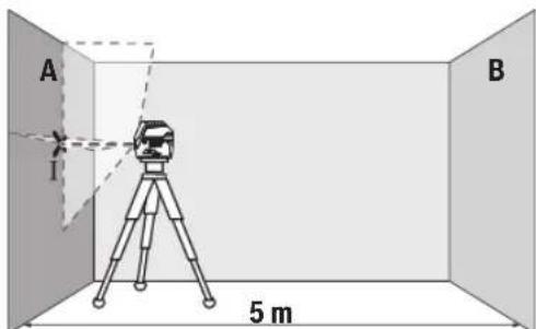
-Hacouete ro nacepot BO 6n3nHa ha Suot A n octabete ro MepHnot ypeJ da ce HBeJInpa. Obenexe te ja CpeINHaTa Ha ToUkata, Kaede Nacepckte IHHnCe BKPCTyBaat Ha Suot (Touka I).
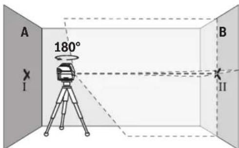
-CbpTeTe ro MePHNOT ype3a 180°,octabete ro da ce HnBEnnpa nO3HaueTe ja ToyKaTa Ha BkPctyBaHe Ha Nacepcknte nnHnHa cnpotNBnTnSd B (Toyka II).
-Noctabete ro MEPHNO type -6e3 da ro BPTHTe -BO 6n3Ha Ha sIOT B, BKnyte ro n octabete ro da ce HbEnpa.
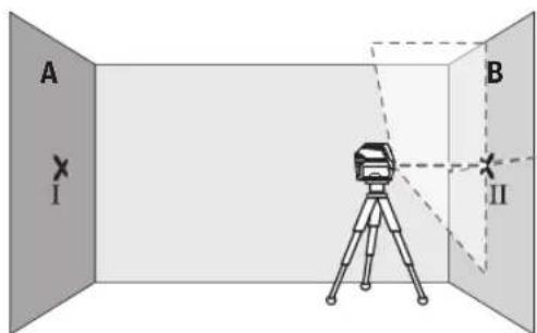
-Noctabete ro MEPHNOYpeI NO BHCnHa (co nOMoH ha CTaHBOT HIN EBEHTyaHIO CO NODrata), Taka ITO TOKATA Ha BKPCTyBaHe Ha Naacepcknte INHHN TOHOr Ke ja NOROIN PEPxOHO O3haueheTa TOKa II Ha SInDor B.

-Cbptete ro MEPHNOt ype3a 180^ 6e3 da ja npomehnte BnCHnHaT. HAcOte Ro Ha sNDOT A, Taka uTO BePTNkAINHATA nacepcka IHHJa npoaf a H3 BeKe O3HaueHa Tocka I. Octabete Ro MEPHNOt ypeI da ce HBeInpa I O3HaueTe ja TOOKata Ha BkpcTyBaHe Ha nacepcknte IHHn Ha sNDOT A (TOKA III).
Pa3nKata dHaDbete O3haeHToUckI I I I HA sHIDOT A ro DaBa 4aKTNUKOTO OTCTanyBaBe OJ BNCnHaTa Ha MEPHNOTypeI.
HaMepHaIHHJaOd2×5m=10mMaKcHMaHnHOToD03BOHeHOOTCTanyBaHe H3HecyBa:
10m×±0,3mm/m=±3mm.Pa3nKataMeFyTouKHTI I Icme da H3HecyBa HajMHORY 3 mm.
PpOBepKa Ha ToUHOCTa HA HnBENHPaBe Ha XOpH3OHTaHATA JHHJia
3a npoBepka, noTpe6Ha Bn e cno6oHa nOBpuHHa oD OKony 5× 5m
-MoHTnpajTe ro MEPHnOT ypeD BO cpeDHa MeFy sIOBHTe A n B h a cTaTb Hnn NocTaBeTe ro Ha CBpCTa, paMHa noIora. H36pePeTe ro xOpH3OHTaIHnOT IHHNCKn peXIM CO aBTOMaTIka 3a HNBENHpAbe HNBENPajTe ro MEPHnOT ypeD.
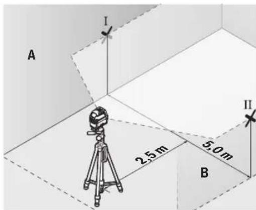
-Ha 2,5 m pactojaHHe oM MepHnotypeI.Ha Dbata sHa O3haueTe ja cpeiHata Ha nacepckata liHHja (Touka I Ha SNDOT A N TOUka II HA SNDDT B).

-Notctabete ro MEPHNOyepd, CBPTeH 3a 180°Ha 5 m pactojaHne n octabete ro da ce HNBennpa.
- Noctabete ro MEPHNO tpei NO BHCnHa (co nomou ha CTaTHBOT HIN EBEHTaIHO CO NOIORATA), Taka ITO CpeHNHaT aHa NacepCKte INHH TOUHO Ke ja NOrOIN npTeXoDHO O3HaueHata ToKa II Ha SInOT B.
Ha snoT A oboEnkeTe ja cpeHnHa Ta Ha nacepckata NHHja kako ToKa III (BepTKaJIHO HAD HIN NOI TOKATA I).
Pa3nKata dHaDbete O3HaueHn Tockn I I I I HA sNDOT A ro daBa paKTNUKOTO oTcanyBaHe Ha MEPHNOT ypeD OXOPN3OHTaIa.
HaMepHaIHHJaO2X5m=10mroDaBaMaKcHMaJIHOTo 03B0NEHOOTCTaYBaHe:
10m×±0,3mm/m=±3mm.Pa3nKata d Mefy TouKnte I n IIIcme da n3HecyBa HajMHOry 3 mm.
PpOBepKa Ha ToUHOCTa Ha HHBenHpaBeTo Ha BePTKkAnHaTAMHHJa
3a KOHTpONa NOTpe6eH Bn eOTBOp Ond BpaTaT, KaIe (Ha CBpCTa NODIora) Ha CEkoJa CTpaHa Ond BpaTata HMa MecTo OJ HajMaNKy 2,5 m.
-Noctabete ro MEPHNOtypeHa 2,5 m pactojaHne od OTBOPOT Ha BpaTata Ha UbpCTa, pAMHa NOIOrA (He Ha cTaHB).N36peTe ro BEPTKANHNO tINHHCKPexHM CO
aBtOMaTHKaTa 3a HnBeHnpaHe. HacOeTe ja Iacepckata nnHJa Ha OTbopoT O BpaTAt N OCTaBe T RO MepHHOType da HnBeHnpa.
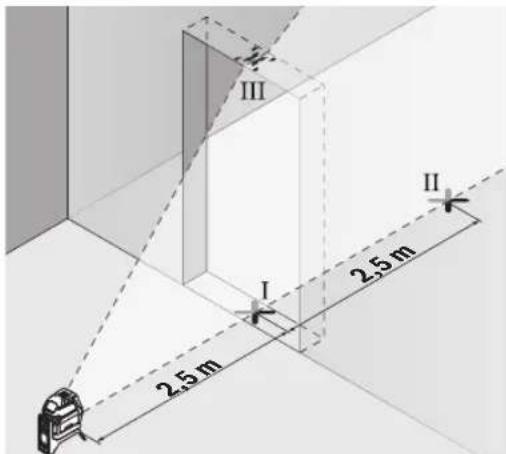
-03haute ja cpeinHata Ha BepTKaHATA nacepcka HnHa Ha nooT od OTBOPoT Ha BpaTata (touka I), Ha 5 m pactoJAHne OD npyrata CTpaHa Ha OTBOPOT OD Bparata (touka II), KaKo H a rOpHnot paHa BA pata Od OTBOPOT (touka III).
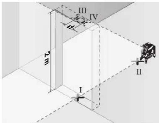
-CBpTeIro MePHNOT ypeJ 3a 180° nIOCTABeTe ro Ha Dpyrata CtpaHa HA OTBOPOT HA BpaTATA dIpeKTHO 3aD Toykata II. OcTabeTe ro MePHNOT ypeJ da CE HINBenipa n HacOyete ja BEPTKANHATA NacepCKA INHInJa Taka ITO HeJ3HNATA CpeINHa Ke NOMHByA TOHNO Hn3 TOOKITE I NII.
-ObenexKeTe ja cpeHnHa Ta HaIacepckTa IHHJa Ha roHNOT pa6 Ha OTBOPOT Ha BpaTata KaKo Tocka IV.
- Pa3nKata d Ha DBeTe O3HaueHn Tockn III IV ro daBa ФakTNKOTO OTCTaNyBaHe Ha MepHnotypeoD BepTKaJIHHTe LHHN.
-Измерета ja Bиснота Ha OTbOPOT OД Врата. Мakсимално ДОЗВолно OTCTAnyBaHе ГпSpecmetyBate HA CLEDHOT HauHH:
IbOJHa BHCnHa Ha OTBOPOT Ha Bpata × 0,3mm / m PnpMep: PnBnCnHa Ha OTBOPOT Ha Bpata O2 m
MaKcHMaHHTO OCTanyBaBe CMee Da H3HeCyBa 2× 2m× ± 0,3mm / m = ± 1,2mm .Tockte III IV Cmeat da
NeXkat HajMHORY 1,2 mm edHa odpyra.
IpoBepKa Ha ToUHocTa Ha IacepCKnOT CHON
3a npOBepkata Notpe6ha Bn e cNoobHa MepHa NHHja Ha Ubpcta noIora co pactoJahne od OKony 5 m nomefy nodot n IpafoHOT.
-MoHTnpajTe ro MEPHnOT ypeHa potaunOHnO TpJkau (23) nIOCTaBeTe ro Ha noDTo. N3bepeTe ro TOUKeCTNoT peKmN OCTaBeTe ro MEPHnOT ypeJa ce HnBeInpa.

- O3haeTe ja cpeHnata Ha rOpHaTna cepcka Touka Ha npaonot (touka I).OcBeH Toa, oBeJeKeTe ja cpeHnata Ha donHaTna cepcka Touka Ha noDor (touka II).
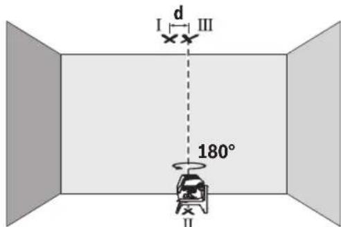
-Cbptete ro MePHnoT ype3a 180°.POnsHnOHaJaTe ro Ha Toj HauHH, ITO cpeHnHaTa Ha DonHata Nacepcka TocKa Ke Jekn Ha BeKe oBeJekaHaTa TocKa II. OCTabeTe ro MePHnoT ype3a ce HbEInpa. ObEnKeTe ja cpeHnHaTa Ha rOpHata Nacepcka TocKa (To4ka III).
Pa3nKaTa dHa DBeTe O3aueHToKu I III Ha PnafoHOT Ro DaBa KaTHKOTO OTCTanyBaHe Ha MepHNOt ypeoD BePTNKaJIHHTe NHHN.
MaKcHmAJHOToIO3B0NEHOOTCTaYBaHe rO npeCMetyBaTe HA CnEHNOT HauHH:
DBOJOHO pAcToJAHNMeFyNoDTNnPaHOT × 0,7mm / m
PpHmep: Pn paactojaHne Mefy noot n npafohot od 5 m MAKCHMaHOTO OCTanyBaHe CMee Da H3HeCyBa
2× 5m× ± 0,7mm / m = ± 7mm .TockteI I IcMeat da nekat hajmory 7 mm eo npya.
Cobetn npa6oTeheTo
3a 06eKyBaBe KOpHCTeJa cekoraUcpeHata Ha nacepckata ToUKa OHN. Nacepckata HHHja.
TolemnHaTa Ha nacepckata ToKa OJH. HnpHaTa Ha nacepckata nnHJa ce MeHyBa corlacho pactoJanHeTo.
MepHnoTyepe o npemeh co 6e3xHueH HHTeppejc.
Tpe6a da ce BHMaba Ha loKaHHTe onepaTHBn orpaHcyBaHa np.Bo aBHOHN Hn6oHnnc.
Pa6otebe co cenHa Ta6na 3a nacepot
LcnHata Tabla 3a nacepot (31) ja nooobpyBa BnInBocTa Ha nacepcknoT 3paK npn HenoBOnHyCNoBn rOeMn pactoJahna.
PeKnTpaKaTaNpBpHnHaHaeHnTaTa6Na Ha nacepot (31) jaNoobpyBa BnINBOCTa Ha nacepckata HnHja, Hn3 TpaHCnapeHTHa TaOBpHnHa nacepckata HnHja e BnNBA H od 3aHnTa CtpaHa Ha eHnTa Ta6Na Ha nacepot.
Pa6oTeHe co cTaTHB (onpeMa)
CtANBOT OBO3MOKByBa Cta6HnHa MepHa NOIInora ITO MoKe Da ce NOpDecyBa No BnCnHa. NocTaBeTe Ro MEPHNOT ypeD co 1/4"-npNpaTOT Ha CTANBOT (18) Ha HABoJOT HA CTaTNBOT (32) INN ObuueH fOTo CTaNB. 3aUbPcTeTe Ro MEPHNOT ypeD CO 3aBPTKa 3a DKKcapAbe Ha CTANBOT.
Ipy6o ceHTnpajTe ro ctaTnBOT, nped da ro BKnyuHMepeHNOtypeN.
Pnucpctete co yHbep3aneh dpka (onpema) (BnD nCnKa L)
Co NOMOHa yHnBep3aHnHOT dpXaU (26) MoKe Da ro npuBcPHTe MepHnOypeH naP. Ha BepTnKaHn IOBpHHn HnMaHETnHpaHn MaTepnJaHn.
YHnBep3aJIHHOTIpKaUHcTO TaKa IIOeH N KaKo IIOeH CTaTHB IN OIOeCHyBa IIOeCyBaIbETo IIO BICnHa HA MepHnOT ypeI.
Ipy6o ceHTnpajte ro yHnBep3aHnnot dpKau (26), nped na ro Bknynte MePHNOType.
Pa6oTebe co nacepckn npHemHK (onpeMa) (BnD cnka L)
Pn HENOBOLH CNBETIOCHN YCNOBn (OCBETNeHa OKOINHa, nIpeKTTH COHcEBN 3paun) Ha IroEmPiactoJAHJa 3a noD6po HAOfAbe Ha NacepCKte IHHN KOpHCTe Ro IacepCKnot PnpemHKn (29).PnpapBoTeBe co Iacepckn PnpemHKn BklyueTe ro pexHMOT Ha npemHKn (BNn "PexmHa npemHKn", Ctpanuca 253).
Nacepcckn 3aWHTTHOQHna (onpema)
Nacepckte 3aHTTHO Ounna ja qHITPpaaT OKOHATA CBETnHa. Ha ToJ HauHH CBETNO HA nacepot NrIeJa NOCBETNo 3a OKOTo.
He Hn Kopnctete Nacepcknte 3aHTTHN Ounna (doonHnTeHa onPema) Kako 3aHTTHN OUnna. Nacepcknte 3aHTTHN Oounna cnjxkat 3n noD6po paCnO3HaBaHbE Ha IacepckNoT 3paK; cenak, Tne He 1tAT od NacepckTo 3pauehe.
He rKoPCHTeI Nacepcknte 3aHTTHN OCHNA (DononHnTeHa onpeMa) KaO OUNa 3a COHcE Hnna KBO COOpaKaJot. Nacepcknte Ounna He daBaat cenocha UV-3aHTTa nTo HaAManyBaat npeno3HaBaeTo Ha60n.
Ppimepn 3a pa6oTa (Bnu n cInk G-M)
PpHmepn 3a MoKHOCTHe Ha pHmeha Ha MePHNOTypeKe HajTe Ha rpaqHKnTe CTpaHn.
OdpKyBaHe n cepBnC
OdpKyBaBe n uHCTeBe
IocjoaHO ODPxyBajTe ja NCTOTATA Ha MEPHnot ypeD. He ro notonybaje MEPHnot ypeD BO BODn DpyrnteHQCTN.
H36pnueTe Hn HeuNcTOnnHe Co BnaXHa MeKa KpNa. He KopncTepeCTBa 3a YnCteHe nn PaTbOpn.
PeIOBHO UCTeTe rN NOBpUHHHTe OKNY N3JIe3HNOr OTBOP HaIacepot IN pntoA BHIMAbajTe HA BnAKeHuaTa.
CepBncha cnyK6a H COBET np KOpHCTeBe
CepBnchata Cnyk6a Ke OngroBOpn Ha BaWnte npaHaBa BO Bpcka co nonpaBkata N odpyBaHeto Ha BaWnOT npo3BOD KAKO IN pe3epBNHTe DeIOBn. O3NaK 3a EKCnIO3nJa INHOPMaun 3a pe3epBNHTe DeIOBn IcTO Taka Ke HajTe Ha: www.bosch-pt.com
TMMOT 3a COBetyBaBe npK KopnCTeHe Ha Bosch Ke Bn NOMORHe DOKOLky HMaTe npaHaHa 3a HaaHte npOn3BDoN onpema.
3a CnTe npaaHbHa HapaKHa pe3epBHN DeNoB,Be MoIInme HabeTe ro 10-ncfpeHHOT 6poj od CneuNkauNHOHa TIOUka Ha npOn3BODoT.
Cebepha MaKeDoHja
Д.Д.Енктпс
CabaKobayek47b,6poj3
1000 Ckonje
E-nouta: dimce.dimcv@servis-bosch.mk
HHTepHET: www.servis-bosch.mk
TeN./φaKc:02/2467610
Mo6.:070595888
Ⅱ.Ⅰ.T.Y“POJKA”
JaHn LyKpOBcKn 66; T.Li ABTOKOMaHaJa loKaI 69
1000 Ckonje
E-nouta: servisrojka@yahoo.com
Ten: +389 2 3174-303
Mo6: +389 70 388-520, -530
IOnonHnTeHH aDpeCN Ha cepBnCH MoKe Da HajTeNoi:
www.bosch-pt.com/serviceaddresses
TpaHcnpT
Ppenopaahnte Htnym-johcn6bateynnoJnEkaH a6apaaHa 3akOHOT 3a onachm Maepujan. Batepnte MoKe da ce tpaHcnpTnpaat cmo od ctpaHa KaOpchNkOt, 6e3 notpe6a od donoHnTeHH KBaHnФKaun.
Pn npneHoc Ha nCTHe Oc TpaHa Ha TpeT Nua (Ha np. Bo3DyWeH TpaHCnOPT Hn WneDnUja) HeONXoHO e Da ce BHIMABA HA CneJauHInTe HAnOMEHN Ha AMbaJata n 03HaKIne. Bo TaKOB Cnyuj, npn NoDrTOBkATA Ha npTaKaTa Mopa Da Ce NOBkA EKcnepT 3a Onacn CyncTahu.
TpaHcnpHpajTe r6batepHnTe cmo DOKoNky KyKnHTeTo e HEOHTeHO.3aIeNETe rTO TBOpEHnTE KOHTACh nCnakyBajTe ja 6batepJata Ha Toj HauHH wTO Hema Da ce DBrNX BO aMbaJxata. Be MoJIme BHNMaBajTe Ha eBEHTyAnHnTe DoONHnTeHN HaUHOHaHn IpOINcN.
OtctpaHyBaBe

MepHnTe ypei, akymlaTopHe/6aTePnTe, onpemataHa am6anakHe Tpe6a Da ce OCTpaHaT Ha ekonoWKn npdaTINB HauHH.
He nФрnajTe Мернite ypeNi 6aTePnnte Bo domaHnata KaHa 3a r6pe!
Cama 3a 3emjnte oEY:
Cnope ebponckata dnpkeTbBa 2012/19/EU 3a ctapn eEeKTPNHN EeKTPoHcN ypeDN HNBHATA ynotpe6a BO hauNoHaHnHO t3aKoHoDaBCTBO, MepHNTe ypeDN ITO CE BOY notpe6a N deEeKTHNE INN NCKOpNCteHNTe 6aTePN CnopeD npkeTbAta 2006/66/EC Mopa OndenHO da ce co6epat n da ce peuknnpaat 3a nobToPHa ynotpe6a.
DOKONky ce oTcpaHyBaat HenpabHnHo, eNEKtpnHata n eNEKtpoHckata onpema MoKe da HMaat WTeTHn BnJaHjaBp3 KINBOTHATA cpeHa H 3IpaJbeto Ha IyreTo nopAn MOKHOTO pncyctBO Ha OpanCH MaTePHN.
Akymylatopck6aTeepn/6aTeepn:
JTHym-jOHCKH:
Be MoJIHMe BHHMaBajTe Ha HAnOMeHHTe BO DeNoT TpaHCnOpT (BnuN, TpaHCnOpT, CtpaHnua 257).
Srpski
- Kompatibilost Bluetooth® 4.0 (Classic Low Energy)Bluetooth® 4.0 (Classic Low Energy)
-Operativni system Android 6 (i visi) Android 6 (i visi)
iOS 11 (i visi) iOS 11 (i visi)
Tezina u skladu sa EPTA-Procedure 01:2014
-
Sa akumulatorom 0,62 kg 0,62 kg
-
Sa baterijama 0,58 kg 0,58 kg
Dimenzije (duzina × sirina × visina)
-Bez drza 136×55×122mm 136×55×122mm
-Saobrtnimdrzaem 0188×180mm 0188×180mm
Vrsta zastite
Preporučena temperatura okruženja prilikom punjenja
Dozvoljena temperatura okrużenja prilikom rada
Dozvoljena temperatura okrużenja prilikom skladiżenia
Preporuceni akumulatori GBA 12V... GBA 12V...
osim GBA 12V≥ 4.0Ah) osim GBA 12V≥ 4.0Ah)
Tackasti ili linijski laser GCL 2-50 C GCL 2-50 CG
Preporuceni punjaic GAL 12...
GAX 18...
GAL 12...
GAX 18...
A) Radno područje može da se smanzi zbog nepovoljinih okolnih uslova (npr. direktnog sunčevog zračenja).
B) na 20-25°C
C) Navedene vrednosti pretpostavlju normalne do povoljne okolne uslove (npr. nema vibracija, nema magle, nema dima, nema direktnog suncevog zracanja). Nakon jakih kolebanja temperature, moze doci do odstupanja u preciznosti.
D) Pojavluje se neprovodljiva zaprljanost, pri cemu se ocekuje privremena provodljivost prouzrokovana rosenjem.
E)Krace vreme rada u Bluetooth®rezimu i/jili u vezi sa RM 3
F) Kod Bluetooth® Low Energy uredaja u zavisnosti od modela i operativnog systema uspostavljanje veze moze da bude onemoguceno. Bluetooth® uredaji moraju da podržavaju SPP profil.
G) zavisi od upotrebljne akumulatorske baterije
H) Littium-jonski akumulator i adapter za baterije AA1 nisu obuhvaceni sa IP 54.
Tehnicki podaci dobijeni sa akumulatorom iz obima isporuke.
Za jasn identifikaciju vaseg mernog uredaja sluji broj articla (19) na plocici sa tipom.
Montaža
www.bosch-pt.com/serviceaddresses
Transport
Preporuceni litijum-jonski akumulatori podlezu zahevima propisa o opasnim materijama. Korisnik moze bez dodatnih uslova transporteovati akumulatore na drumu.
Kod slanja preko trecih lica (na primer vazdušnih transportom ili špedicijom) mora se obrati za na posebne zahteve u pogledu pakovanja i označavanja. Tada se kod pripreme paketa za slanje mora pozvati strucnjak za opasne materije.
Akumulatorske baterije saljite samo aku kuciSTE nije osteceno. Odlepitote otvorene kontakte i upakujte akumulatorsku bateriju tako, da se nePokrece u paketu. Molimo da obratite paznju na eventualne dalje nationalne propise.
Uklanjanje dubreta

Merne alate, akumulatore/baterij, pribor i pakovanja treba predatna reciklazu koja je u skladu sa zašitom zivotne sredine.
Merne alate i akumulatorske baterije/baterij nemojte bacati u kuconi opdat!
Samo za EU-zemlje:
Prema evropskoj direktivi 2012/19/EU o starim elektricnim i elektronskim uredajima i njenoj primeni u nacionalnom pravu, merni alati koji se visne megu koristiti, a prema evropskoj direktivi 2006/66/EC akumulatori/baterije koje su u kvar ili astrosene moraju se odvojeno sakupljati i ukluciti u reciklazu koja ispunjava ekoloske uslove.
Download on the App Store

GET IT ON Google Play
Download on the App Store

GET IT ON Google Play
Uklučivanje Bluetooth®
Za uklučivanje Bluetooth® za daljinsko upravljanje pritisnite Bluetooth® tipku (10). Provjerite je li na vašem mobilnom krajnjem uredaju aktivirano Bluetooth®-sućelje.
NakonPokretanja Boschaplakacije uspostavlja se veza izmedu mobilnog krajnjeg uredaja imjernog alata.Ako se pronade visaktivni mjernih alata, odaberite odgovarajuCi mjerni alat.Ako se pronade samo jeganaktivni mjerni alat, veza se automatski uspostavlja.
www.bosch-pt.com/serviceaddresses
Transport
Preporucene litij-ionske aku-baterije podljezu zakun o transportu opasnih tvari. Korisnik bez ikakvih preduvjeta moze transportirati aku-baterije cestovnim transportom. Ako transport obavlja treca strana (npr. transport zrakoplovom ili speficija), treba se pridržavati posebnih zahtjeva za ambalaizu označavanje. Kod pripreme ovakvih posiljki za transport prethodno se treba savjetovati sa strucnjakom za transport opasnih tvari.
Aku-bateriju saljite nekim transportnim sredstvomismo ako je njezino kuciSTE neoostecono. Oblijepite otvorene kontakte i zapakirajte aku-bateriju takdo sa se ne moze pomicati u ambalazi. Pridrzavaje se i eventualnih dodatnih nacionalnih propisa.
Zbrinjavanje

Mjerne alate, aku-baterije/baterije, pribor i ambalazu treba dovesti na ekološki prihvatljivo recikiranje.
Mjerne alate i aku-baterije/baterije ne bacajte u kučni otpad!
Samo za zemlje EU:
U skladu s europskom Direktivom 2012/19/EU o elektrichim i elektronickim starim uredajima i njihovom provedbom u nacionalno pravo neupotrebljivi mjrnii alati i u skladu s europskom Direktivom 2006/66/EZ neispravne ili istrosene aku-baterije/baterije moraju se odvojeno sakupljati i dovesti na ekoloski prihvatljivo recikliranje.
U slucaju nepravilnog zbrinjavanja elektrichi i elektronicki stari uredaji mogu imati stetne ucinke na okolis i ljudsko zdravlje zbog moguce prisutnosti opasnih tvari.
Download on the App Store

GET IT ON Google Play
Bluetooth® sisselilutamine
Bluetooth®kaugjuhtimise sisselulitamiseks vajutage Bluetooth®-nuppu (10). Veenduge, et Bluetooth®-liides on teie mobilises loppseadmes aktiveeritud.
www.bosch-pt.com/serviceaddresses
Transport
Darbs ar stativu (papildiederums)
Stativs ir icerae regulejamu augstumu, kas paredzeta merinstrumenta stabilai nostiprinasaanai. Novietojiet merinstrumentu uz stativa ta, lai ta vitne (18) atrastos pret stativa (32) vai tirdznieciba piejama fotostativa 1 / 4 " stiprinajuma skruvi. Stingri pieskruejiet merinstrumentu ar stativa stiprinajuma skruvi.
Pirms merinstrumenta ieslegsanas aptuveni izlidzinent stativu.
Nostiprināsana ar universā tureṭa ja palidzibu (papildiederums) (attels L)
Lazera skatbrilles (papildiederums)
www.bosch-pt.com/serviceaddresses
Transportesana
Iteicamajiem litja jonu akumulatoriem ir piemerojami Bistamo kravu aprites likuma noteikumi. Lietotajs var transportet akumulatorus ielu transporte plusma bez papildun nosacijumiem.
Parsutot tos ar treso personu starpniecibu (piemeram, ar gaisa transporta vai citu transporta agenturu starpniecibu), jiaevero ipasiti sutijuma iesainosanas un markesanas noteikumi. Tapec sutijumu sagatavoosanas laikajapieaicina bistamo kravu parvadasanas specialists.
Parsutiet akumulatoru tikai tad, ja ta korpussn nav bojats. Aizlimejiet valejos akumulatora kontaktus un iesainojiet akumulatoru ta, lai tas iesainojuma neparvietotos. Ludzam ieverot ari ar akumulatoru parsutisanu saistitos nacionlos noteikumus, ja tadi pastav.
www.bosch-pt.com/serviceaddresses
Transportavimas
Rekomenduojamu licio jonj akumulatoriuy gabinemui taikomos pavojingku kroviniu gabenima reglamentuojanciuy jstatymu nuostatos. Naudotojui akumulatorius gabenti kelais leidziami be jokiuy apribojmu.
Jei siunciant pasitelkiami tretieji asmenys (pvz., oro transports, ekspedijavimo jmoné), butina atsiizvelgtj j pakuoteir zenklinimui taikomus ypatingus reikalavimus. Butina, kad rengiant siunta dalyvauty pavojingu kroviniu gabenimo specialistas.
www.bosch-pt.com/serviceaddresses
運搬
Download on the App Store

GET IT ON Google Play
接通蓝牙
www.bosch-pt.com/serviceaddresses
搬运
www.bosch-pt.com/serviceaddresses
搬運
| 이��드에 편일 끼이지 | GCL 2-50 C GCL 2-50 CG | |
| 상품만 기재 썸고다 => -> => => => => => => => => => => => => => => => => => => => => => => => => => => => => => => => => => => => => => => => => => => => => => => => => => => => => => => => => => => => => => => => => => => => => => => => => => => => => => => => => => => => => => => => => => => => => => => => => => => => => >> => >> => >> => >> => >> => >> => >> => >> => >> => >> => >> => >> => >> => >> => >> => >> => >> => >> => >> => >> => >> => >> => >> => >> => >> => >> => >> => >> => >> => >> => >> => >> => >> => >> => >> => >> => >> => >> => >> => >> => >> => >> => >> => >> => >> => >> => >> => >> => >> => >> => > >> => >> => >> => >> => >> => >> => >> => >> => >> => >> => >> => >> => >> => >> => >> => >> => >> => >> => >> => >> => >> => >> => >> => >> => >> => >> => >> => >> => >> => >> => >> => >> => >> => >> => >> => >> => >> => >> => >> => >> => >> => >> => >> => >> => >> => >> => >> => >> => >> => >> = >> = >> = >> = >> = >> = >> = >> = >> = >> = >> = >> = >> = >> = >> = >> = >> = >> = >> = >> = >> = >> = >> = >> = >> = >> = >> = >> = >> = >> = >> = >> = >> = >> = >> = >> = >> = >> = >> = >> = >> = >> = >> = >> = >> = >> = >> = >> = >> = >> = >> <|im_start|>assistant <p>상품만 기재 썸고다 => -> => => >> => >> >> >> >> >> >> >> >> >> >> >> >> >> >> >> >> >> >> >> >> >> >> >> >> >> >> >> >> >> >> >> >> >> >> >> >> >> >> >> >> >> >> >> >> >> >> >> >> >> >> >> >> >> >> >> >> >> >> >> >> >> >> >> >> >> >> >> >> >> >> >> >> >> >> >> >> >> >> >> >> >> >> >> >> >> >> >> >> >> >> >> >> >> >> >> >> >> >> >> >> = >> >> = >> >> = >> >> = >> >> = >> >> = >> >> = >> >> = >> >> = >> >> = >> >> = >> >> = >> >> = >> >> = >> >> = >> >> = >> >> = >> >> = >> >> = >> >> = >> >> = >> >> = >> >> = >> >> = >> >> = >> >> = >> >> = >> >> = >> >> = >> >> = >> >> = >> >> = >> >> = >> >> = > >> = >> >> = >> >> = >> >> = >> >> = >> >> = >> >> = >> >> = >> >> = >> >> = >> >> = >> >> = >> >> = >> >> = >> >> = >> >> = >> >> = >> >> = >> >> = >> >> = >> >> = >> >> = >> >> = >> >> = >> >> = >> >> = >> >> = >> >> = >> >> = >> >> = >> >> = >> >> = >> >> = >> > >> = >> >> = >> >> = >> >> = >> >> = >> >> = >> >> = >> >> = >> >> = >> >> = >> >> = >> >> = >> >> = >> >> = >> >> = >> >> = >> >> = >> >> = >> >> = >> >> = >> >> = >> >> = >> >> = >> >> = >> >> = >> >> = >> >> = >> >> = >> >> = >> >> = >> >> = >> >> = >> >> = > > >> = >> >> = >> >> = >> >> = >> >> = >> >> = >> >> = >> >> = >> >> = >> >> = >> >> = >> >> = >> >> = >> >> = >> >> = >> >> = >> >> = >> >> = >> >> = >> >> = >> >> = >> >> = >> >> = >> >> = >> >> = >> >> = >> >> = >> >> = >> >> = >> >> = >> >> = >> >> = >> >> = >>>> <p>상품만 기재 썸고다 => -> => => >> => >> >> >> >> >> >> >> >> >> >> >> >> >> >> >> >> >> >> >> >> >> >> >> >> >> >> >> >> >> >> >> >> >> >> >> >> >> >> >> >> >> >> >> >> >> >> >> >> >> >> >> >> >> >> >> >> >> >> >> >> >> >> >> >> >> >> >> >> >> >> >> >> >> >> >> >> >> >> >> >> >> = >> >> = >> >> = >> >> = >> >> = >> >> = >> >> = <p>상품만 기재 썸고다 => -> => => >> => >> >> >> >> >> >> >> >> >> >> >> >> >> >> >> >> >> >> >> >> >> >> >> >> >> >> >> >> >> >> >> >> >> >> >> >> >> >> >> >> >> >> >> >> >> >> >> >> >> >> >> >> >> >> >> >> >> >> >> >> >> >> >> >> >> >> >> >> >> >> >> >> >> >> >> >> >> >> >> >> >> > >> >> = >> >> = >> >> = >> >> = >> >> = >> >> = >> >> = >> >> = >> >> = >> >> = >> >> = >> >> = >> >> = >> >> = >> >> = >> >> = >> >> = >> >> = >> >> = >> >> = >> >> = >> >> = >> >> = >> >> = >> >> = >> >> = >> >> = >> >> = >> >> = >> >> = >> >> = >> >> = >> >> = >>></p> | ||
。,RaiiJHbIroIhHe DaRn的NbiBnS 十
-ReiJrBnAnG(ACKSRE)R)日中BnAnG以
- ReiJr BnAnGg(ACKSRE)u 1000000000000000000000000000000000000000000000000000000000
著作日
www.bosch-pt.com/serviceaddresses
是
则当有之,即能为国。
3a 3
表端在上,如能用。
司

yauuuaaunauuuuauuuuuuuuuuuuuuuuuuuuuuuuuuuuuuuuuuuuuuuuuuuuuuuuuuuuuuuuuuuuuuuuuuuuuuuuuuuuuuuuuuuuuuuuuuuuuuuuuuuuuuuuuuuuuuuuuuuuuuuuuuuuuuuuuuuuuuuuuuuuuuuuuuuuuuuuuuuuuuuuuuuuuuuuuuuuuuuuuuuuuuuuuUU
aannnnnnae aen nnnnne anennnne
aannnnnnaanennnnae
aunnnnnaannnnnnnnnnnnnnnnnnnnnnnnnnnnnnnnnnnnnnnnnnnnnnnnnnnnnnnnnnnnnnnnnnnnnnnnnnnnnnnnnnnnnnnnnnnnnnnnnnnnnnnnnnnnnnnnnnnnnnnnnnnnnnnnnnnnnnnnnnnnnnnnnn
aunnnnnaanannnnnnaanennnnaanennnnnnaanennnnnnaanannnnnnaanannnnnnaanannnnnnaanannnnnnaanannnnnnaanannnnnnaanannnnnnaanannnnnnaanannnnnnaanannnnnnaanannnnnnaanannnnnnaanannnnnnaanannnnnnaanannnnnnaanannnnnnaanannnnnnaanannnnnnaanannnnnnaanannnnnnaanennnnaanannnnnnaanannnnnnaanannnnnnaanannnnnnaanannnnnnaanannnnnnaanannnnnnaanannnnnnaanannnnnnaanannnnnnaanannnnnnaanannnnnnaanannnnnnaanannnnnnaanannnnnnaanannnnnnaanannnnnnaanannnnnnaanannnnnnaanann
aovvovovovovovovovovovovovovovovovovovovovovovovovovovovovovovovovovovovovovovovovovovovovovovovovovovovovovovovovovovovovovovovovovovovovovovovovovov
aunnnnnaanannnnnnnnnnnnnnnnnnnnnnnnnnnnnnnnnnnnnnnnnnnnnnnnnnnnnnnnnnnnnnnnnnnnnnnnnnnnnnnnnnnnnnnnnnnnnnnnnnnnnnnnnnnnnnnnnnnnnnnnnnnnnnnnnnnnnnnnnnnnnn
aunnnnnaannnnnnnnnnnnnnnnnnnnnnnnnnnnnnnnnnnnnnnnnnnnnnnnnnnnnnnnnnnnnnnnnnnnnnnnnnnnnnnnnnnnnnnnnnnnnnnnnnnnnnnnnnnnnnnnnnnnnnnnnnnnnnnnnnnnnnnnnnnnnnnn
A
aannnnnnaanrnnnnae annnnnne nnnnne
Wnwnwunwnnnnwnnnn nn nnnnnnnnnnnnnnnnnnnnnnnnnnnnnnnnnnnnnnnnnnnnnnnnnnnnnnnnnnnnnnnnnnnnnnnnnnnnnnnnnnnnnnnnnnnnnnnnnnnnnnnnnnnnnnnnnnnnnnnnnnnnnnn
nnaananaananaananaananaananaananaananaananaananaananaananaananaananaananaananaananaananaananaananaananaananaananaananaananaananaananaananaananaananaananaananaananaananaananaananaananaananaananaananaananaananaananaananaananaananaananaananaananaananaananaanaraannnnnnnnnnnnnnnnnnnnnnnnnnnnnnnnnnnnnnnnnnnnnnnnnnnnnnnnnnnnnnnnnnnnnnnnnnnnnnnnnnnnnnnnnnnnnnnnnnnn
Tnunannn n. u.nu nnolnu wou nnnnnaan an an annnnnnae aen annnnaaennnnnne ennnnnae ennnnnnne ennnnnnne ennnnnnne ennnnnnne ennnnnnne ennnnnnne ennnnnnne ennnnnnne ennnnnnne ennnnnnne ennnnnnne ennnnnnne ennnnnnne ennnnnnne ennnnnnne ennnnnnne ennnnnnne ennnnnnne ennnnnnne ennnnnnne ennnnnnnee ennnnnnne ennnnnnne ennnnnnne ennnnnnne ennnnnnne ennnnnnne ennnnnnne ennnnnnne ennnnnnne ennnnnnne ennnnnnne ennnnnnne ennnnnnne enann
nnaaannnnnnaan nanaan an naan anan aan anan anan anan anan anan anan anan anan anan anan anan anan anan anan anan anan anan anan anan anan anan anan anan anan anan anan anan anan anan anan anan anan anan anan anan anan anan anan anan anan anan anan anan
1uunuaaunwauanrwnnnaeunnnnun
ywnnnn nn nnnnnnnnnnnnnnnnnnnnnnnnnnnnnnnnnnnnnnnnnnnnnnnnnnnnnnnnnnnnnnnnnnnnnnnnnnnnnnnnnnnnnnnnnnnnnnnnnnnnnnnnnnnnnnn

unuuaananaaannnnaa anu u. u. uuuuauauauauauauauauauauauauauauauauauauauauauauauauauauauauau

nannnnnnaaennnnnnae nnnnnnne nnnnnnne nnnnnnne nnnnnnne nnnnnnne nnnnnnne nnnnnnne nnnnnnne nnnnnnne nnnnnnne nnnnnnne nnnnnnne nnnnnnne nnnnnnne nnnnnnne nnnnnnne nnnnnnne nnnnnnne nnnnnnne nnnnnnne nnnnnnnee nnnnnnne nnnnnnne nnnnnnne nnnnnnne nnnnnnne nnnnnnne nnnnnnne nnnnnnne nnnnnnne nannnne nannnne nannnne nannnne nannnne nannnne nannnne nannnne nannnne nannnne nannnne nannnne nannnne nannnne nannnne nannnne nannnne nannnne nannnne nannnne nannnne nannnne nannnne nannnne nannnne nenn
nannnnnnnnnnnnnnnnnnnnnnnnnnnnnnnnnnnnnnnnnnnnnnnnnnnnnnnnnnnnnnnnnnnnnnnnnnnnnnnnnnnnnnnnnnnnnnnnnnnnnnnnnnnnnnnnnnnnnnnnnnnnnnnn
nannnnnnnnnnnnnnnnnnnnnnnnnnnnnnnnnnnnnnnnnnnnnnnnnnnnnnnnnnnnnnnnnnnnnnnnnnnnnnnnnnnnnnnnnnnnnnnnnnnnnnnnnnnnnnnnnnnnnnnnnnnn
27 17 17 17 17 17 17 17 17 17 17 17 17 17 17 17 17 17 17 17 17 17 17 17 17 17 17 17 17 17 17 17 17 17 1
nauuunnaaunnuu uanuunnuuauuauuauuauuauuuuauuuuuuuuuuuuuuuuuuuuuuuuuuuuuuuuuuuuuuuuuuuuuuuuuuuuuuuuuuuuuuuuuuuuuuuuuuuuuuuuuuuuuuuuuuuuuuuuuuuuuuuuuuuuuuuuuuuuuuuuuuuuuuuuuuuuuuuuuuuuuuuuuuuuuuuuuuuuuuuuuuuuuuuuuuuuuuuuuuuuuuuuuuuuuuuuuuuuuuuuuUU
alulnuuauauauauuuuauuauauauauauauuuuuuuuuuuuuuuuuuuuuuuuuuuuuuuuuuuuuuuuuuuuuuuuuuuuuuuuuuuuuuuuuuuuuuuuuuuuuuuuuuuuuuuuuuuuuuuuuuuuuuuuuuuuuuuuuuuuuuuuuuuuuuuuuuuuuuuuuuuuuuuuuuuuuuuuuuuuuuuuuuuuuuuuuUU
IwuaanTu:
nuaanrnnnnaaannnnnnaaannnnnnaaannnnaaannnnnnaaannnnnnaaannnnnnaaannnnnnaaannnnnnaaannnnnnaaannnnnnaaannnnnnaaannnnnnaaannnnnnaaannnnnnaaannnnnnaaannnnnnaaannnnnnaaannnnnnaaannnnnnaaannnnnnaaannnnnnaaannnnnnaaannnnnnaaann
LED
100-75%
75-35%
[ \ln n = \frac{y}{x} ]
LisitunwL -
-uuuunnnnun2
wuuuunnnnnaaannnnnnaaennnnnnnnnnnnnnnnnnnnnnnnnnnnnnnnnnnnnnnnnnnnnnnnnnnnnnnnnnnnnnnnnnnnnnnnnnnnnnnnnnnnnnnnnnnnnnnnnnnnnnnnnn
nunuunnuunruaLM2 (nnw Jnn A1-A3)
360° 3
nunnnnnnnnnnnnnnnnnnnnnnnnnnnnnnnnnnnnnnnnnnnnnnnnnnnnnnnnnnnnnnnnnnnnnnnnnnnnnnnnnnnnnnnnnnnnnnnnnnnnnnnnnnnnnnnnnnnnnnnnnnnnnnnnnnnnnnnnnnnnnnnn nn (24)
(1)(20)
nunnuuunuunuuuunnnnun (2)
nuucunnu "on" uunnuunununnuu (5)
nuuaauauauauauauauauauu uuuuuuuuuuuuuuuuuuuuuuuuuuuuuuuuuuuuuuuuuuuuuuuuuuuuuuuuuuuuuuuuuuuuuuuuuuuuuuuuuuuuuuuuuuuuuuuuuuuuuuuuuuuuuuuuuuuuuuuuuuuuuuuuuuuuuuuuuuuuuuuuuuuuuuuuuuuuuuuuuuuuuuuuuuuuuuuuuuuuuuuuuuuuuuuuuuuuuuuuuUU
nannnnnnu Bluetooth®
Bnblnblnblnblnblnblnblnblnblnblnblnblnblnblnblnblnblnblnblnblnblnblnblnblnblnblnblnblnblnblnblnblnblnblnblnblnblnblnblnblnblnblnblnblnblnblnblnblnblnbln
366
Bosch (Apps) wouwnnnaunn nnnn nn nnnn nn nnnnnnnnnnnnnnnnnnnnnnnnnnnnnnnnnnnnnnnnnnnnnnnnnnnnnnnnnnnnnnnnnnnnnnnnnnnnnnnnnnnnnnnnnnnnnnnnnnnnnnnnnnnnnnnnnnnnnnnnnnnnnnnn

Download on the App Store

GET IT ON Google Play
nntuNnuu Bluetooth®
Bnwnnnn nnnn nnnn nnnn nn nnnn nnnn nnnn nnnn nnnn nnnn nnnn nnnn nnnn nnnn nnnn nnnn nnnn nnnn nnnn nnnn nnnn nnnn nnnn nnnn nnnn nnnn nnnn nnnn nnnn nnnn nnnn nnnn nnnn nnnn nnnn nnnn nnnn nnnn nn
Bosch uunuunuunu unuunuunuunuunuunuunuunuunuunuunuunuunuunuunuunuunuunuunuunuunuunuunuunuunuunuunuunuunuunuunuunuunuunuunuunuunuunuunuunu
mTa 9
nblt 1000000000000000000000000000000000000000000000000000000000000000000
nDnDnDnDnDnDnDnDnDnDnDnDnDnDnDnDnDnDnDnDnDnDnDnDnDnDnDnDnDnDnDnDnDnDnDnDnDnDnDnDnDnDnDnDnDnDnDnDnDnDn
WnwnnwnnblnntnBleetohn nnnnnnnnnae 1na lnnoynnblueotho (10)
n7777777777777777777
W
y
nnaaannnnnnnnnnnnnnnnnnnnnnnnnnnnnnnnnnnnnnnnnnnnnnnnnnnnnnnnnnnnnnnnnnnnnnnnnnnnnnnnnnnnnnnnnnnnnnnnnnnnnnnnnnnnnnnnnnnnnnnnnnnnnnnnnnnnnnnnnnnnnnnnnnnnnnnnnnnn
Hnnnnaaannnnaaennnnnnaanennnnnne
nunnnnuuunnu) nunnuuunnuuunnuu uuuu uuuu uuuuuuuuuuuuuuuuuuuuuuuuuuuuuuuuuuuuuuuuuuuuuuuuuuuuuuuuuuuuuuuuuuuuuuuuuuuuuuuuuuuuuuuuuuuuuuuuuuuuuuuuuuuuuuuuuuuuuuuuuuuuuuuuuuuuuuuuuuuuuuuuuuuuuuuuuuuuuuuuuuuuuuuuuuuuuuuuuuuuuuuuuuuuuuuuuuuuuuuuuUU
nannnnnnaaennnnnnnnnnnnnnnnnnnnnnnnnnnnnnnnnnnnnnnnnnnnnnnnnnnnnnnnnnnnnnnnnnnnnnnnnnnnnnnnnnnnnnnnnnnnnnnnnnnnnnnnnnnnnnnnnnnnnnnnnnnnnnnnnnnnnnnnnnnnn nn nannnne annn nannn nannn nannn nannn nannn nannn nannn nannn nannn nannn nannn nannn nannn nannn nannn nannn nannn nannn nannn nannn nannn nannn nannn nannn nannn nannn nannn nannn nannn nannn nannn nannn nannn nann
mnnnnaaannnnnnnnnnnnnnnnnnnnnnnnnnnnnnnnnnnnnnnnnnnnnnnnnnnnnnnnnnnnnnnnnnnnnnnnnnnnnnnnnnnnnnnnnnnnnnnnnnnnnnnnnnnn
nunnnnnaaannn nn nnnnnnnn 5 u. uu
一 1
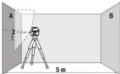
- 1AaAaBaaBaaBaaBaaBaaBaaBaaBaaBaaBaaBaaBaaBaaBaaBaaBaaBaaBaaBaaBaaBaaBaaBaaBaaBaaBaaBaaBaaBaaBaaBaaBaaBaaBaaBaaBaaBaaBaaBaaBaaBaaBaaBaaBaaBaaBaaBaaBaaBaaBaaBAA (qnaI)
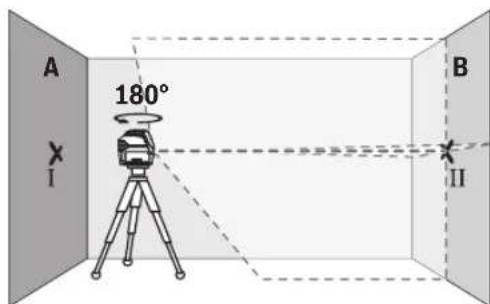
-nyuun 180° uouuiuuaauiuauu
- 177777777777777777777777777777777777777
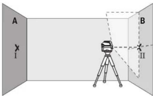
- 7777777777777777777777777777777777777777777777777777
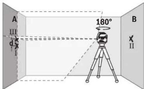
180° 1uuluuuunuunuun uuuuA uunuunuunuunuunuun uuuuuuuuuuuuuuuuuuuuuuuuuuuuuuuuuuuuuuuuuuuuuuuuuuuuuuuuuuuuuuuuuuuuuuuuuuuuuuuuuuuuuuuuuuuuuuuuuuuuuuuuuuuuuuuuuuuuuuuuuuuuuuuuuuuuuuuuuuuuuuuuuuuuuuuuuuuuuuuuuuuuuuuuuuuuuuuuuuuuuUU
一a 111
A uan anan anan anan anan anan anan anan anan anan anan anan anan anan anan anan anan anan anan anan anan anan anan anan anan anan anan anan anan anan anan anan anan anan anan anan anan anan anan anan anan anan anan anan
10x.±0.3u./u. =±3u.前n7d 1 u.Ⅲiuiu 3 u.
n 5x5.
一 1
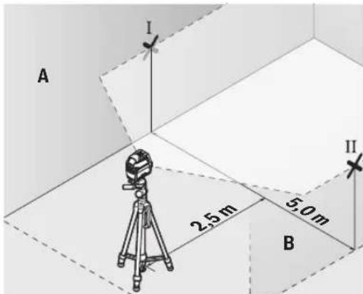
-2.5u.nnnaaannnnnnaa nnnnnnnaa aannnnnnaaannnnnnaa
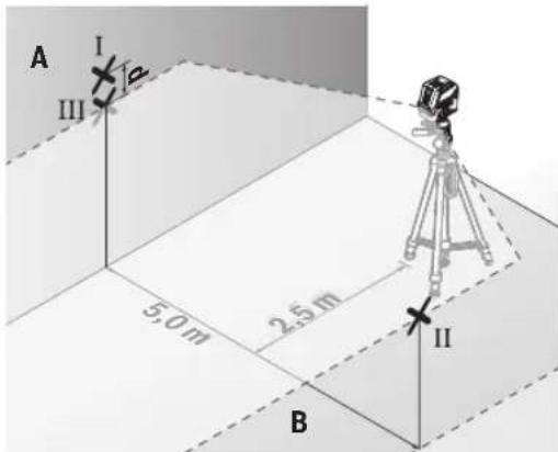
- 5u.180°
- 1
- nnnnnaaannnnaananaananaananaananaananaananaananaananaananaananaananaananaananaananaananaananaananaananaananaananaananaananaananaananaananaananaananaananaananaananaananaananaananaananaananaananaananaananaananaananaananaananaananaananaananaananaananaananaananaananaanara an
- 10000000000000000000000000000000000000000000000000000000000000000
2×5.10 1
- × ± 0.3 131./3. = ± 3 131. 前的d
nannnnnnaaennnnnnae nnnnnnne nnnnnnne nnnnnnne nnnnnnne nnnnnnne nnnnnnne nnnnnnne nnnnnnne nnnnnnne nnnnnnne nnnnnnne nnnnnnne nnnnnnne nnnnnnne nnnnnnne nnnnnnne nnnnnnne nnnnnnne nnnnnnne nnnnnnne nnnnnnnee nnnnnnne nnnnnnne nnnnnnne nnnnnnne nnnnnnne nnnnnnne nnnnnnne nannnne nannnne nannnne nannnne nannnne nannnne nannnne nannnne nannnne nannnne nannnne nannnne nannnne nannnne nannnne nannnne nannnne nannnne nannnne nannnne nannnne nannnne nannnne nannnne nannnne nenn
368
-777777777777777777777777777777777777777777777777
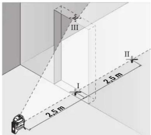
nnuuunnuuunnuuunnuuunnuuuu uuuuuuuuuuuuuuuuuuuuuuuuuuuuuuuuuuuuuuuuuuuuuuuuuuuuuuuuuuuuuuuuuuuuuuuuuuuuuuuuuuuuuuuuuuuuuuuuuuuuuuuuuuuuuuuuuuuuuuuuuuuuuuuuuuuuuuuuuuuuuuuuuuuuuuuuuuuuuuuuuuuuuuuuuuuuuuuuuuuuuuuuuuuuuuuuuuuuuuuuuUU
www.bosch-pt.com/serviceaddresses
#
Palma Tower 10th Floor
Jalan RA Kartini II-S Kaveling 6
Pondok Pinang, Kebayoran Lama
www.bosch-pt.com/serviceaddresses
Transpor
www.bosch-pt.com/serviceaddresses
Vanhuyen
Pin Li-lion duoc khuyen nghi la doi tuong phai tuan theo cac qui dinh cua Phap Luat ve Hang Hoa Nguyen Hiem. Ngu di su dung co the van chuyen pin hgp khoi bang dong bo ma khong can them yeu cau nao khac.
Khi duoc van chuyen thong qua ben thu ba (vd.
van chuyen bang duong hang khong hay dai ly giao
nhan), thai tuan theo cac yeu cau dac biét ve dong
gói va dan nhan. Thai tham van chuyen gia ve
hang hónguyi hieh khi chuán bi goiHang.
Chi gui pin hop khoi khi vongaikhong bi hong. Dän bang keo hay che kin cac diem tiep xuc ho va dong goi pin hop khoi theo cach sao cho pin khong the xedich khi nam trong bao bi.Ngoai ra, xin vui long chap hanh cac qui dinh chi tiét co the duoc bo sung them cua quoc gia.
Su thai bo

May do, acqui/pin, phu kien va bao bi can ducc tai su dung theo quy dinh vmei truong.
Khong vut dung cu do va pin/ac quy cung trong rac thai cua gia dinh!
Pin:
Li-Ion:
Tuan tu nhung hong dan trong phan v an chuyen (xem,Van chuyen",Trang 391).
gJ gJ j J J J J J J J J J J J J J J J J J J J J J J J J J J J J J J J J J J J J J J J J J J J J J J J J J J J J J J J J
J 100000000000000000000000000000000000000000000000000000000000000000000
g 1sLg yollll jia aal lal 1
15 g 9g .aai IyI 10
gljag aai alal ayuayk 10
10 g 1001 g ai dia 10
. abraag dgiw
42 g 1001 g 10
42 g 1001 g 10
42 g 1001 g 10
42 g 1001 g 10
42 g 1001 g 10
42 g 1001 g 10
(a) UJUJI JgLgO/ogj jjj (15)
(a) U JuaJ LgaoaLaaLae (16)
jU|u a
1/4 glll jololjol (18)
Juluaaia jll (19)
a du gjll dSω (20)
(a) uub li 21
(a) Cuii
(23)
aJgJJ JooJgJooJgJ (24)
(a) cawwclu (25)
(a) (26)
[a_j j g, d, a, a, a, a, a, a, a, a, a, a, a, a, a, a, a, a, a, a, a, a, a, a, a, a, a, a, a, a, a, a, a, a, a, a, a, a, a, a, a, a, a, a, a, a, a, a, a, a, a, a, a,]
(3) _n=1^ n^2n+1
^aj_iu| 1Jaiuo (29)
日 日 山 山 山 山 山 30
(a) jU U ggi dgl (31)
(a) g g g g g g g g g g g g g g g g g g g g g ^ 2 10a (32)
(a) _g_m_l
(a) aolg aoo (34)
(a)u|bullggo (35)
(a) wJdJI (36)
Lai jy dLaIgill gill .gail
IJIbUJg aabJlg ojgs
JUJIJI JUW UCL) JUJAI auiu JJgX1g
2.15. (auiJI UclawI, uJJI Ujpo pbiO
gJ Jd gss
- yjll gblill jn algaiI liigai
aiai jgjll wluall o sii
aabJjQeJI Jn JyJbL Bluetooth
UgLoJI gIooog gggjUgjjU Ubaog
2.jaij1 jbs lg9 dss gll biaallg
aaii o gjoll walf po sss
Jluu JjUjUjUj Bluetooth
Jaujagaluo Lgacgbsol
LgIgJawg Bluetooth@ sJlo pWl
Bluetooth SIG, aJwJ Lg g, dssaa
jloJaw/AsJolI pWgSsWiI sI Inc.
Robert Bosch Power Tools GmbH
Uaui Uo pui
1g aaiI 0g
JgJgJgJgJgJgJgJgJg
Jsui
Jusss
aagbIgblssuul (wauo ooc
. soluillblaj yI aLoyU Iog aJgosllg
aJg JdJl GJLaaWU WlaIoo
0sc 1J RM2 JlgJU JolJI gJb jS
aJ6oJdoJI abai Ug aJ 360 aUglj uJlu
jjU IgbiI guiu. uug.laJoo
uull oSc ggo jg d
oJgaaal |j5
wJaiIoojgwsJl jgaaal1jzai
aababaaIgawll aaaa oogagll
JUJJ1J11
labg juiu 2
(aaggall gllgll sllcI gllgllg (3)
UJb/psJnJwAa (4)
JgduJJ Joo (5)
aiaiIul
GCL 2-50 CGCL 2-50 CG
3601K66G..3601K66H..
g j
aioll
aJaaI gIbu
20 20
p50-5p50-5
10 10
10 10
-aauJj1bga
-jiuljiaiwo 20
-1e1jjjjaiabai
-awlJjUlaa
(C)gaw81baw a9
394
| GCL 2-50 CGCL 2-50 CG | ||
| ±4° ±4° | JLJLJLJLJLJLJLJLJLJLJLJLJLJLJLJLJLJLJLJLJLJLJLJLJLJLJLJLJLJLJLJLJLJLJLJLJLJLJLJLJLJLJLJLJLJLJLJLJLJLJ L | |
| 4 > 4 > | JLJLJLJLJLJLJLJLJLJLJLJLJLJLJLJLJLJLJLJLJLJLJLJLJLJLJLJLJLJLJLJLJLJLJLJLJLJLJLJLJLJLJLJLJLJLJLJLJ L | |
| 90 %90 % | JLJLJLJLJLJLJLJLJLJLJLJLJLJLJLJLJLJLJLJLJLJLJLJLJLJLJLJLJLJLJLJLJLJLJLJLJLJLJLJLJLJLJLJLJLJLJLJLJ J | |
| D)2 | JLJLJLJLJLJLJLJLJLJLJLJLJLJLJLJLJLJLJLJLJLJLJLJLJLJLJLJLJLJLJLJLJLJLJLJLJLJLJLJLJLJLJLJLJLJLJLJLJ | |
| 2 | JLJLJLJLJLJLJLJLJLJLJLJLJLJLJLJLJLJLJLJLJLJLJLJLJLJLJLJLJLJLJLJLJLJLJLJLJLJLJLJLJLJLJLJLJLJLJLJL J | |
| jJJ jJJ jJJ jJJ jJJ jJJ jJJ jJJ jJJ jJJ jJJ jJJ jJJ jJJ jJJ jJJ jJJ jJJ jJJ jJJ jJJ jJJ jJJ jJJ jJJ jJJ jJJ jJJ jJJ jJJ jJJ jJJ jJJ jJJ jJJ jJJ jJJ jJJ jJJ jJJ jJJ jJJ jJJ jJJ jJJ jJJ jJJ jJJ jJJ jJJ jJJ J J J J J J J J J J J J J J J J J J J J J J J J J J J J J J J J J J J J J J J J J J J J J J J J J J J J J J J J J J J J J J J J J J J J J J J J J J J J J J J J J J J J J J J J J J J J J J J J J J J J jJJ jJJ jJJ jJJ jJJ jJJ jJJ jJJ jJJ jJJ jJJ jJJ jJJ jJJ jJJ jJJ jJJ jJJ jJJ jJJ jJJ jJJ jJJ jJJ jJJ jJJ jJJ jJJ jJJ jJJ jJJ jJJ jJJ jJJ jJJ jJJ jJJ jJJ jJJ jJJ jJJ jJJ jJJ jJJ jJJ jJJ jJJ jJJ jJJ jjj jjj jjj jjj jjj jjj jjj jjj jjj jjj jjj jjj jjj jjj jjj jjj jjj jjj jjj jjj jjj jjj jjj jjj jjj jjj jjj jjj jjj jjj jjj jjj jjj jjj jjj jjj jjj jjj jjj jjj jjj jjj jjj jjj jjj jjj jjj jjj jjj jjj jJJ J J J J J J J J J J J J J J J J J J J J J J J J J J J J J J J J J J J J J J J J J J J J J J J J J J J J J J J J J J J J J J J J J J J J J J J J J J J J J J J J J J J J J J J J J J J J J J J J J jll l l l l l l l l l l l l l l l l l l l l l l l l l l l l l l l l l l l l l l l l l l l l l l l l l l l l l l l l l l l l l l l l l l l l l l l l l l l l l l l l l l l l l l l l l l l l l l l l l l l l jll l l l l l l l l l l l l l l l l l l l l l l l l l l l l l l l l l l l l l l l l l l l l l l l l l l l l l l l l l l l l l l l l l l l l l l l l l l l l l l l l l l l l l l l l l l l l l l l l jll g g g g g g g g g g g g g g g g g g g g g g g g g g g g g g g g g g g g g g g g g g g g g g g g g g g g g g g g g g g g g g g g g g g g g g g g g g g g g g g g g g g g g g g g g g g g g g g g g g g gg g g g g g g g g g g g g g g g g g g g g g g g g g g g g g g g g g g g g g g g g g g g g g g g g g g g g g g g g g g g g g g g g g g g g g g g g g g g g g g g g g g g g g g g g g g g g g g g g g g g jll l l l l l l l l l l l l l l l l l l l l l l l l l l l l l l l l l l l l l l l l l l l l l l l l l l l l l l l l l l l l l l l l l l l l l l l l l l l l l l l l l l l l l l l l l l l l l l l l f jll l l l l l l l l l l l l l l l l l l l l l l l l l l l l l l l l l l l l l l l l l l l l l l l l l l l l l l l l l l l l l l l l l l l l l l l l l l l l l l l l l l l l l l l l l l l l l l l l d jll l l l l l l l l l l l l l l l l l l l l l l l l l l l l l l l l l l l l l l l l l l l l l l l l l l l l l l l l l l l l l l l l l l l l l l l l l l l l l l l l l l l l l l l l l l l l l l l l t jll l l l l l l l l l l l l l l l l l l l l l l l l l l l l l l l l l l l l l l l l l l l l l l l l l l l l l l l l l l l l l l l l l l l l l l l l l l l l l l l l l l l l l l l l l l l l l l l l ll jll l l l l l l l l l l l l l l l l l l l l l l l l l l l l l l l l l l l l l l l l l l l l l l l l l l l l l l l l l l l l l l l l l l l l l l l l l l l l l l l l l l l l l l l l l l l l l l l l I jll l l l l l l l l l l l l l l l l l l l l l l l l l l l l l l l l l l l l l l l l l l l l l l l l l l l l l l l l l l l l l l l l l l l l l l l l l l l l l l l l l l l l l l l l l l l l l l l l L jlll jll jll jll jll jll jll jll jll jll jll jll jll jll jll jll jll jll jll jll jll jll jll jll jll jll jll jll jll jll jll jll jll jll jll jll jll jll jll jll jll jll jll jll jll jll jll jll jll jll jll jell jll jll jll jll jll jll jll jll jll jll jll jll jll jll jll jll jll jll jll jll jll jll jll jll jll jll jll jll jll jll jll jll jll jll jll jll jll jll jll jll jll jll jll jll jll jll jll jll jll jill jll jll jll jll jll jll jll jll jll jll jll jll jll jll jll jll jll jll jll jll jll jll jll jll jll jll jll jll jll jll jll jll jll jll jll jll jll jll jll jll jll jll jll jll jll jll jll jll jll jIll jll jll jll jll jll jll jll jll jll jll jll jll jll jll jll jll jll jll jll jll jll jll jll jll jll jll jll jll jll jll jll jll jll jll jll jll jll jll jll jll jll jll jll jll jll jll jll jll jll jillo 10 | jll jll jll jll jll jll jll jll jll jll jll jll jll jll jll jll jll jll jll jll jll jll jll jll jll jll jll jll jll jll jll jll jll jll jll jll jll jll jll jll jll jll jll jll jll jll jll jll jll jll jll jll jll jll jll jll jll jll jll jll jll jll jll jll jll jll jll jll jll jll jll jll jll jll jll jll jll jll jll jll jll jll jll jll jll jll jll jll jll jll jll jll jll jll jll jll jll jll jll jell jll jll jll jll jll jll jll jll jll jll jll jll jll jll jll jll jll jll jll jll jll jll jll jll jll jll jll jll jll jll jll jll jll jll jll jll jll jll jll jll jll jll jll jll jll jll jll jll jll jill jll jll jll jll jll jll jll jll jll jll jll jll jll jll jll jll jll jll jll jll jll jll jll jll jll jll jll jll jll jll jll jll jll jll jll jll jll jll jll jll jll jll jll jll jll jll jll jll jll iLL iLL iLL iLL iLL iLL iLL iLL iLL iLL iLL iLL iLL iLL iLL iLL iLL iLL iLL iLL iLL iLL iLL iLL iLL iLL iLL iLL iLL iLL iLL iLL iLL iLL iLL iLL iLL iLL iLL iLL iLL iLL iLL iLL iLL iLL iLL iLL iLL iLL iLL jll jll jll jll jll jll jll jll jll jll jll jll jll jll jll jll jll jll jll jll jll jll jll jll jll jll jll jll jll jll jll jll jll jll jll jll jll jll jll jll jll jll jll jll jll jll jll jll jll J jll l l l l l l l l l l l l l l l l l l l l l l l l l l l l l l l l l l l l l l l l l l l l l l l l l l l l l l l l l l l l l l l l l l l l l l l l l l l l l l l l l l l l l l l l l l l l l l l jll l ll l l l l l l l l l l l l l l l l l l l l l l l l l l l l l l l l l l l l l l l l l l l l l l l l l l l l l l l l l l l l l l l l l l l l l l l l l l l l l l l l l l l l l l l l l l l l l l l l l l l I jill jll jll jll jll jll jll jll jll jll jll jll jll jll jll jll jll jll jll jll jll jll jll jll jll jll jll jll jll jll jll jll jll jll jll jll jll jll jll jll jll jll jll jll jll jll jll jll jll jll k k k k k k k k k k k k k k k k k k k k k k k k k k k k k k k k k k k k k k k k k k k k k k k k k k k k k k k k k k k k k k k k k k k k k k k k k k k k k k k k k k k k k k k k k k k k k k k k k k k k jll k k k k k k k k k k k k k k k k k k k k k k k k k k k k k k k k k k k k k k k k k k k k k k k k k k k k k k k k k k k k k k k k k k k k k k k k k k k k k k k k k k k k k k k k k k k k k k k k jll jll jll jll jll jll jll jll jll jll jll jll jll jll jll jll jll jll jll jll jll jll jll jll jll jll jll jll jll jll jll jll jll jll jll jll jll jll jll jll jll jll jll jll jll jll jll jll jlljll jll k k k k k k k k k k k k k k k k k k k k k k k k k k k k k k k k k k k k k k k k k k k k k k k k k k k k k k k k k k k k k k k k k k k k k k k k k k k k k k k k k k k k k k k k k k k jll k k k k k jll k k k k k jll k k k k k jll k k k k k jll k k k k k jll k k k k k jll k k k k k jll k k k k k jll k k k k k jll k k k k k jll k k k k k jll k k k k k jll k k k jll k k k jll k k jll k jll k jll k jll k jll k jll k jll k jll k jll k jll k jll k jll k jll k jll k jll k jll k jll k jll k jll k jll k jll k jll k jll k jll k jll k jell jell jell jell jell jell jell jell jell jell jell jell jell jell jell jell jell jell jell jell jell jell jell jell jell jell jell jell jell jell jell jell jell jell | |
395
| GCL 2-50 CGCL 2-50 CG | الجعاني بعبيا | ||
| pès 0,62 pès 0,62 | (عmcملاوي – | ||
| pès 0,58 pès 0,58 | -الجعاني بعبيا | ||
| (عmcملاوي × مصحيطالعاء)الجعاني | |||
| pès 122 × 55 × 136 | pès 122 × 55 × 136 | -الجعاني | |
| pès 180 × 188 بpscبique | pès 180 × 188 بpscبique | -الجعاني | |
| (الجعاني بpscبique مصحيطالعاء) IP 54 | (الجعاني بpscبique مصحيطالع eighteen) IP 54 | (عmcمleaوي رهانسونسونسونسونسونسونسونسونسونسونسونسونسونسونسونسونسونسونسونسونسونسونسونسونسونسونسونسونسونسونسونسونسونسونسونسونسونسونسونسونسونسونسونسونسونسونسونسونسونسونسistonسونسistonسistonسistonسistonسistonسistonسistonسistonسistonسistonسistonسistonسistonسistonسistonسistonسistonسistonسistonسistonسistonسistonسistonسistonسistonسistonسistonسistonسistonسistonسistonسistonسistonسistonسistonسistonسistonسistonسistonسistonسistonسistonسistonسistonسistonسistonسistonسistonسistonسistonسloonسistonسloonسistonسloonسistonسloonسistonسloonسistonسloonسistonسloonسistonسloonسistonسloonسistonسloonسistonسloonسistonسloonسistonسloonسistonسloonسistonسloonسistonسloonسistonسloonسistonسloonسistonسloonسistonسloonسistonسloonسistonسloonسistonسloonسistonسloonسistonسloonسistonسistonسloonسistonسloonسistonسloonسistonسloonسistonسloonسistonسloonسistonسloonسistonسloonسistonسloonسistonسloonسistonسloonسistonسloonسistonسloonسistonسloonسistonسloonسistonسloonسistonسloonسistonسloonسistonسloonسistonسloonسistonسloonسistonسloonسistonسloonسistonسloonسloonسistonسloonسistonسloonسistonسloonسistonسloonسistonسloonسistonسloonسistonسloonسistonسloonسistonسloonسistonسloonسistonسloonسistonسloonسistonسloonسistonسloonسistonسloonسistonسloonسistonسloonسistonسloonسistonسloonسistonسloonسistonسloonسistonسloonسistonسloonسistonسloonسloonسistan | (عmcمleaوي رهانسونسونسونسistonسloonسistonسloonسistonسloonسistonسloonسistonسloonسistonسloonسistonسloonسistonسloonسistonسloonسistonسloonسistonسloonسistonسloonسistonسloonسistonسloonسistonسloonسistonسloonسistonسloonسistonسloonسistonسloonسistonسloonسistonسloonسistonسloonسistonسloonسistonسloonسistonسlowest sic |
| pès 50+...pès 10- | pès 50+...pès 10- | الجعاني | |
| pès 70+...pès 20- | pès 70+...pès 20- | الجعاني | |
| GBA 12V... (dclw↑ GBA 12V ≥ 4.0 | sec lo) | GBA 12V... (dclw↑ GBA 12V ≥ 4.0 | sec lo) | الجعاني | |
| GAL 12... | GAL 12... | الجعاني | |
| GAX 18... | GAX 18... |
.(aJUALLJUULI JUJIIL:) aJUALLJUJLbJUULJUJUJUJU
0^25 - 20日 aJdaJic (B
ggsjgljglssg) aaiia gaiabaaalagjllg jol gssall pall jusl bun (C
aJl aJg Gg Lg
aaggo ygul gao gao gao gao gao gao gao gao gao gao gao
RM 3 0gblg g/9 Bluetooth@ jaiy
y.
pssssspsssss (G
.1P54aJalaiagjoguiuAA1aJIbUJIgogoguUugiH
aallll lblg jgrralln aaiiaaii
gall 19)Jusuall pJ Jg>J.2gj gai all o
yduuull joguiuulUugjpoaLao pJ aiguiLulai dagabwlg
"Electronic Cell Protection (ECP)"
EJIOI 1000
Download on the App Store

GET IT ON Google Play
Bluetooth®
Bb 10) Bt 10. j 10
Jl Jj 10
Jj 10
Jj 10
Jj 10
Jj 10
Jj 10
Jj 10
Jj 10
Bluetooth® wgo Iosic j Jus
aJluuBleoth 1 Jau jn k jLj g wJlQ o s c y g aIg aIg aIg bIg IwblzoggJU WgWgJUgBlueth 8 Jwgo Jw
Bluetooth®
bdu jc kblu bI11Bleoth@ clk 0sc lalj g (10) Bleeth@jj J .wJd
wullloocg 1500
aJUc ojgo Jolgc
JL JU 1000000000000000000000000000000000000000000000000000000000000000000000000000000000000000
Ugul Uo Uo Uo Uo Uo Uo Uo Uo Uo Uo Uo Uo Uo Uo Uo Uo Uo Uo Uo Uo Uo Uo Uo Uo Uo Uo Uo Uo Uo Uo Uo Uo Uo Uo Uo Uo Uo Uo Uo Uo Uo Uo Uo Uo Uo Uo Uo Uo Uo Uo U0U0U0U0U0U0U0U0U0U0U0U0U0U0U0U0U0U0U0U0U0U0U0U0U0U0U0U0U0U0U0U0U0U0U0U0U0U0U0U0U0U0U0U0U0U0U0U0U0U0U0
Jaaunol da
(29)jUJIJIaIIOJIOJIOJIOJIOJIOJIOJIOJIOJIOJIOJIOJIOJIOJIOJIOJIOJIOJIOJIOJIOJIOJIOJIOJIOJIOJIOJIOJIOJIOJIOJIOJIOJIOJIOJIOJIOJIOJIOJIOJIOJIOJIOJIOJIO
(6) jll lbc baoi Jaiuall aabj uaiu Jiaai 7) wgol
sic oJauoJIuJIb gbsaagj ayksol Jai
jull Jaiuwo ng Jaaell Jaiuall aabj Uusw Jiaai wall ao Jia jlo gla p
.(6)Jaiuall aoabjjle Ldo
.(7) Jaiuall aoabjUy Gabiy
a gwll a
(B-EJgJJI) aGwJl JI gJfJU 10 gJgJUaJgJI Uc wJUJUoJg .(23) JlgJJUJLJU LqjUuJJ jU, aGwJl JI pJdSjU JI U. "On gJl (2) JIyJg
JU 1000000000000000000000000000000000000000000000000000000000000000000000000000000000000000000
UuUgla UaUeU 0,3UUaig EaU J 2 UUaig EaJI UgSloUc:Uu UaI UgS UaI UaI UaI UaI UaI UaI UaI UaI UaI UaI UaI UaI UaI UaI UaI UaI UaI UaI UaI UaI UaI UaI UaI UaI UaI UaI UaI UaI UaI UaI UaI UaI UaI UaI
Solaill abai a9s
wagao aayaiy jaoil ySJ 5 ggea aui Jla
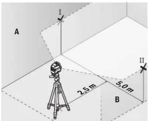
-2,5
aaii iiaai 1

-1c°180jIddoo
-1olalakwlg)
agwulpogai Lgjgl 5
-11111110811111111111
sic laia Iw gog Ula Jg pIgall jlll
aay jull bcauio cuy (oJg)
.B Jssll lcl uauj Gw lll abail
-AJdALIc1llab
-1c juaolllg
(31) jjU U g uu u u u u u u u u u u u u u u u u u u u u u u u u u u u u u u u u u u u u u u u u u u uu uuuuuuuuuuuuuuuuuuuuuuuuuuuuuuuuuuuuuuuuuuuuuuuuuuuuuuuuuuuuuuuuuuuuuuuuuuuuuuuuuuuuuuuuuuuuuuuuuuuuuuuuuuuuuuuuuuuuuuuuuuuuuuuuuuuuuuuuuuuuuuuuuuuuuuuuuuuuuuuuuuuuuuuuUU
aaii aaii 100g iagwll gaii waiI e xj
-23)1gJlJolJL
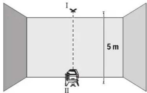
-(1abai)cawuJ
jUI abai jauu g, uJ 1 aJgU. (II abail) jOJI ylc auWl

JUULI JUULI abai aaiia iabiu 1uulll oec .ll juaui gwiill abaiil abaii jauu p. lili sgiw Ibuay agai Jull) JJUUI djjj jubi xnnn annl) JJU
-1c 1jiaolaiI IHIgI
gglj no yalai o s yia gla t coa w

bis(gj) jllgagagagagagagagagagagagagagagagagagagagagagagagagagagagagagagagagagagagagagagagagagagagagagagagagagagagagagagagagagagagagagagagagagagagagagagagagagagagag
JdJd
Robert Bosch Morocco SARL
gssoojllg53
LJ120300
+212529314327:JJI
sav.outillage@ma.bosch.com: 一 _ 1 ^ 一 gj
:aa aal glic no yjol s
www.bosch-pt.com/serviceaddresses
Jai
UbIJWgOgGgU UgU
pogj paxaalqaa.ogblslgol jglg
bguauiu 100
aGlo
jai:la jai jbi jbi jc qllwj puy lo sic
aIbgsuagulggy(jawdajgglgall
a oaiwI yaiy. aaiy g aaiy
jau yloic jabal lgJai uao
.1JlJI 0d gdiaw jall pSjll
LgK 1515 10
LauJgWSSOJI Lwosoll aBsu
y. 2 2 2 2 2 2 2 2 2
.1g nlaeaiiaaiaaaiaaiaaiaiaiaiaiaiaiaiaiaiaiaiaiaiaiaiaiaiaiaiaiaiaiaiaiaiaiaiaiaiaiaiaiaiaiaiaiaiaiaiaiaiaiaiaiaiaiaiaiaiaiaiaiaiaiaiaiaiaiaia
aJgSll oSll
/psjollg wlll lss jy yalil
sIgog aulokilll lalolllg UjU
Lalao g sJl jI jI g Iiuiuai Jy JI yuuiuuiuoi Uio slj yuuiuuiuuiuuiuuiuuiuuiuuiuuiuuiuuiuuiuuiuuiuuiuuiuuiuuiuuiuuiuuiuuiuuiuuiuuiuuiuuiuuiuuiuuiuuiuuiuuiuuiuuiuuiuuiuuiuuiuuiuuiuuiuuiuuiuuiuuiuuiuuiuuiuuiu ui uuuuuuuuuuuuuuuuuuuuuuuuuuuuuuuuuuuuuuuuuuuuuuuuuuuuuuuuuuuuuuuuuuuuuuuuuuuuuuuuuuuuuuuuuuuuuuuuuuuuuuuuuuuuuuuuuuuuuuuuuuuuuuuuuuuuuuuuuuuuuuuuuuuuuUU
g uublio sljluu jll j 19 g uublioo yuua lglkws
wJl
j0s0o0s j0g0jgc sglqgj 1jdaiaolgi Gdi Ja djaed
auiy 5jL
L
LawjJjJl.
julai jssu JwJjul Jusu 4u wuguaa aaa aaa aagg jil
oljao oosw jwjljsw cwsy jglj l jgsgss jj d olsw j wipuubnuee
g jj 1234567890101123456789010112345678901011234567890101123456789010112345678901011234567890101123456789010112345678
sjjw sjiy Lg sjiy u w w g y J 1y 1y 1u 1u 1u 1u 1u 1u 1u 1u 1u 1u 1u 1u 1u 1u 1u 1u 1u 1u 1u 1u 1u 1u 1u 1u 1u 1u 1u 1u 1u 1u 1u 1u 1u 1u
RM 2 jLjSjL (A1-A3 uJd jEg)
ojil jiljglg 23) jlaosjlsas
Sjlo gaiu dbai uga 360o jolil ayu
go digsi. jia, cwi o suaa uIg dauam ds
ojil jiljulagoo jui jujl bgs ulgi
s pabii uus
bgs uglg 24) qo pabiuy Ss a
s pabi yobai jqds lols I jui sgaoc
Slae Egi pabi
sU y sSoc ggi jusg slg oJsljI Jy Loo SLoa nol jnloj wng lgo aS :suiu u e gig g klail
g juLi gla ay ssgac g aaj jui baa Su l jui logba. yu g kui ay ssgac jui abai Su .Sis G yagjy am u da j 90° aglj
.
. 1uU Ggdu y Sgac jU gui Js sS oJl ulj u jf j Uo J
Jluu JJU abai sU caw Js Sgac jU ba
.5gW O OUs
Jlgus sS oJl ulj u jI u j U
GsO uJL uJai jU ba Su Sgac jU ba
.(360°)JULi
. 1uU Lg U g u y s gac ju Jlgl G U S abai jslac Ja u Lslae pao Iaill Jgulg U p m g SuIogil jui p
Download on the App Store

GET IT ON Google Play
J 25 J 25 J 25 J 25 J 25
jai jii
/5j1w g jj1s j1j1 jla uu j Jg 1j1u

:GolglSjJ/5jJwSgJjL
:Jgogj
Jaa 1
.uis agj (413 aow, "olsiw
(G-MgLaJdAsEgJ)LacStU
oJjIjI jUJL UUJU dUJ JUdigai
.510xuuao uLguglaa aao j 5
uugw9 CJr
www.bosch-pt.com/serviceaddresses
olius Jaa
IoljUgawOswdogjgoguJSLsJLsJLsJGooJSLsJLsJLsJLs
Jusu jui 10sau u g y I s
gJaaL) UaawbawjUwJUgJ
duuBogoo Uauo Jdy (uooj ly gao jai
J. 1Jg Dggo 5JlSIOg g Ss
Jluajdeo sJluo L aia yu uoy
. 5d ajo y 50K L Juauiu
Lai dss sss JwJgJb0jI jyju Ijlu (sIqSli) 2uai .swu o ysi wI Jds ss ss daw g jygu g Ja a lal oJy J. gdi Jsu dau uu .dagj Lgoldoi g
Licenses
Copyright © 2012-2020 STMicroelectronics
All rights reserved.
Redistribution and use in source and binary forms, with or without modification, are permitted provided that the following conditions are met:
- Redistributions of source code must retain the above copyright notice, this list of conditions and the following disclaimer.
- Redistributions in binary form must reproduce the above copyright notice, this list of conditions and the following disclaimer in the documentation and/or other materials provided with the distribution.
Neither the name of STMicroelectronics nor the names of its contributors may be used to endorse or promote products derived from this software without specific prior written permission.
THIS SOFTWARE IS PROVIDED BY THE COPYRIGHT HOLDERS AND COLNTRIBUTORS "AS IS" AND ANY EXPRESS OR IMplied WARRANTIES, INCLUDING, BUT NOT LIMITED TO, THE IMPLIED WARRANTYES OF MERCHANTABILITY AND FITNESS FOR A PARTICULAR PURPOSE ARE DISCLAIMED. IN NO EVENT SHALL THE COPYRIGHT OWNER OR COLNTRIBUTORS BE LIABLE FOR ANY DIRECT, INDIRECT, INCIDENTIAL, SPECIAL, EXEMPLARY, OR CONSEQUENTIAL DAMAGES (INCLUDING, BUT NOT LIMITED TO, PROCEDURE OF SUBSTITUTE GOODS OR SERVICES; LOSS OF USE, DATA, OR PROFITS; OR BUSINESS INTER-RUPTION) HOWEVER CAUSED AND ON ANY THEORY OF LIABILITY, WHETHER IN CONTRACT, STRICT LIABILITY, OR TORT (INCLUDING NEGLIGENCE OR OTHERWISE) ARISING IN ANY WAY OUT OF THE USE OF THIS SOFTWARE, EVEN IF ADJISSED OF THE POSSIBILITY OF SUCH DAMAGE.
Copyright notes
COPYRIGHT © 2020
TOSHIBA ELECTRONIC DEVICES & STORAGE CORPORATION ALL RIGHTS RESERVED
THE SOURCE CODE AND ITS RELATED DOCUMENTATION IS PROVIDED "AS IS". TOSHIBA ELECTRONIC DEVICES & STORAGE CORPORATION MAKES NO OTHER WARRANTY OF ANY KIND, WHETHER EXPRESS, IMPLIED OR, STATUTORY AND DISCLAIMS ANY AND ALL IMPLIED WARRANTY OF MERCHANTABILITY, SATISFACTORY QUALITY, NON INFRINGEMENT AND FITNESS FOR A PARTICULAR PURPOSE.
THE SOURCE CODE AND DOCUMENTATION MAY INCLUDE ERRORS. TOSHIBA ELECTRONIC DEVICES & STORAGE CORPORATION RESERVES THE RIGHT TO INCORPORATE MODIFICATIONS TO THE SOURCE CODE IN LATER REVISIONS OF IT, AND TO MAKE IMPROVEMENTS OR CHANGES IN THE DOCUMENTATION OR THE PRODUCTS OR TECHNOLOGIES DESCRIBED THEREIN AT ANY TIME.
TOSHIBA ELECTRONIC DEVICES & STORAGE CORPORATION SHALL NOT BE LIABLE FOR ANY DIRECT, INDIRECT OR CONSEQUENTIAL DAMAGE OR LIABILITY ARISING FROM YOUR USE OF THE SOURCE CODE OR ANY DOCUMENTATION, INCLUDING BUT NOT LIMITED TO, LOST REVENUES, DATA OR PROFITS, DAMAGES OF ANY SPECIAL, INCIDENTAL OR CONSEQUENTIAL NATURE, PUNITIVE DAMAGES, LOSS OF PROPERTY OR LOSS OF PROFITS ARISING OUT OF OR IN CONNECTION WITH THIS AGREEMENT, OR BEING UNUSABLE, EVEN IF ADVISED OF THE POSSIBILITY OR PROBABILITY OF SUCH DAMAGES AND WHETHER A CLAIM FOR SUCH DAMAGE IS BASED UPON WARRANTY, CONTRACT, TORT, NEGLIGENCE OR OTHERWISE.
1
| de | Hiermit erklart Robert Bosch Power Tools GmbH, dass der Funkanlage typ GCL 2-50 C/GCL 2-50 CG der Richtlinie 2014/53/EU entspricht. Der vollständige Text der EU-Konformitätserklärung ist unter der folgenden Internetadressee verfügbar: |
| en | Hereby, Robert Bosch Power Tools GmbH declares that the radio equipment type GCL 2-50 C/GCL 2-50 CG is in compliance with Directive 2014/53/EU. The full text of the EU declaration of conformity is available at the following internet address: |
| fr | Le soussigné, Robert Bosch Power Tools GmbH, déclare que l'équipment radioélectrique du type GCL 2-50 C/GCL 2-50 CG est conforme à la directive 2014/53/EU. Le texte complet de la déclaration UE de conformité est disponible à l'adresse internet suivante: |
| es | Por la presente, Robert Bosch Power Tools GmbH declares que el tipo de equipo radioélectrico GCL 2-50 C/GCL 2-50 CG est conformé con la Diretiva 2014/53/EU. Il此文 complète de la déclaration UE de conformità est disponible en la direction Internet suivente: |
| pt | A abaixa assinada Robert Bosch Power Tools GmbH declares que o presente tipo de équipimento de rádio GCL 2-50 C/GCL 2-50 CG est é a conformidade com a Diretiva 2014/53/EU. O此文 integral da交代ação de conformidade está disponível no seguinto endereço de Internet: |
| it | Il fabricante, Robert Bosch Power Tools GmbH, dichiara che il tipo di apparecchiatura radio GCL 2-50 C/GCL 2-50 CG é conformale alla direttiva 2014/53/EU. Il此文 completo della dichiarazione di conformità UE é disponible al seguito indirizzo Internet: |
| nl | Hierbij verkaar ik, Robert Bosch Power Tools GmbH, dat het type radioapparatuur GCL 2-50 C/GCL 2-50 CG conform is met Richtlijn 2014/53/EU. De volledige tekst van de EU-conformiteitsverklaring kan worden geraadpleegd op het volgende internetadres: |
| da | Hermed erklasser Robert Bosch Power Tools GmbH, at radioudystyrstypen GCL 2-50 C/GCL 2-50 CG er i overensstemmelse med direktiv 2014/53/EU. EU-overensstemmelseserkräingens fulde tekst kan findes på følgende internetadresse: |
| sv | Härmed fösakrar Robert Bosch Power Tools GmbH attenna typ av radioutrustning GCL 2-50 C/GCL 2-50 CG overensstämmer med direktiv 2014/53/EU. Den fullständiga texten till EU-fösakrnan om overensstämme finns på foljande webbadress: |
| no | Robert Bosch Power Tools GmbH erklasser herved at radioustyrstypen GCL 2-50 C/GCL 2-50 CG er i overensstemmelse med direktivet 2014/53/EU. Den fullstandige teksten i EU-samsvarserkräingen er tilgengelig auf følgende nettadresse: |
| fi | Robert Bosch Power Tools GmbH vakuuttaa, etta radiolaitetyppi GCL 2-50 C/GCL 2-50 CG on direktiivin 2014/53/EU mukainen. EU-vaatimustemmukaisusvakuutukuten täysittainen teksti on saatavilla seuraavassa internetosoitteessa: |
| el | Me tvn napooua o/n Robert Bosch Power Tools GmbH, δηλωνει οτιοράσεξαμιος GCL 2-50 C/GCL 2-50 CG πλροι tvn obnyia 2014/53/EE. To πλήρες κελίνεον της δηλωσός συμύρφωσε EE διαίθεται στην ακδλουθη στοσελίδα στο διαδικίuο: |
| tr | Robert Bosch Power Tools GmbH, GCL 2-50 C/GCL 2-50 CG radyo ekipmani tipinin Direktif 2014/53/EU ile uyumlu oldugunu borian eder. AB uygunluk borian niam tam metnine asagidaki internet adresinden ulasabilirsiniz: |
| pl | Robert Bosch Power Tools GmbH ninejsym oswiadzca, ze typ urzadzenia radiowego GCL 2-50 C/GCL 2-50 CG jest zgodny z dyrektywja 2014/53/EU. Pelny tekst deklaraci z godnosci UE jest dostepny pod nastujacym adresem internetowym: |
| cs | Timto Robert Bosch Power Tools GmbH prohlaseje, ze typ radiosého zařizenji GCL 2-50 C/GCL 2-50 CG je v souladu se směrnici 2014/53/EU. Üplné zněni EU prohlaseni o shodé je k disposizi na tefo internetové adrese: |
| sk | Robert Bosch Power Tools GmbH týmto vyhlasuje, ze radioséz zariadenie typu GCL 2-50 C/GCL 2-50 CG je v sulaide so smernicou 2014/53/EU. Üplné EU vyhlasenie o zhode je k disposizicii na tejo internetovej adrese: |
| hu | Robert Bosch Power Tools GmbH igazolja, hogy a GCL 2-50 C/GCL 2-50 CG típusú radiosberendezés megfelela a 2014/53/EU irányelnek. Az EU-megfelelo ségi nyilatkozat teljes szövege elérhetó a követkežo internetes címen: |
| ru | Сим Robert Bosch Power Tools GmbH zárabláneč, чу радиоборudованип Ттуна GCL 2-50 C/GCL 2-50 CG cootbetCTbyeДиректaven 2014/53/EU. С пелнымTekстом д��арцио о cootbetCTbvi EU можно ознakомпсь по седушему Иnterpnet-адесу: |
| uk | Сим Robert Bosch Power Tools GmbH zárabláne, чу радиobладаннь Ттуна GCL 2-50 C/GCL 2-50 CG вдіnobідае Директaven 2014/53/EU. 3 navим tekstом д��арцио вдіnobідіrosti EU можся ознakомпсь за takочи Intеретаadrecopo: |
| II | |
| kk | Осыmen Robert Bosch Power Tools GmbH Kompanhines GCL 2-50 C/GCL 2-50 CG Tprinjenri paiano Жабдьтардь 2014/53/EU Д配电ивасьна садыгш Марлмады. EO садкесх Марлмдамсь темендени Интерnet мекенкида калжетимд: |
| ro | Prin preventa, Robert Bosch Power Tools GmbH declararca tipul de echipamente radio GCL 2-50 C/GCL 2-50 CG este in conformitate cu Directiva 2014/53/UE. Textul integral al declaraţiei UE de conformitate este disponibil la urmätoarea adresä internet: |
| bg | С насточто Robert Bosch Power Tools GmbH Д配电ирава, чу тоши падносяпгпсьогьенье GCL 2-50 C/ GCL 2-50 CG e в сботоветспve с Д配电ива 2014/53/EC. Радостни ТЕКТ на EC Д配电ирава за сботоветспve mootа на се насдени Иntерnet Tradп: С ова, Robert Bosch Power Tools GmbH почртува дка тинот на радно onрера GCL 2-50 C/GCL 2-50 CG Бо согласноct co Д配电ива差别 2014/53/EU. ЛобочитTekт на Из jabата за сoudрацны на EU може на ro почитafe на се насдени Иntерnet Tradп: Со ова, Robert Bosch Power Tools GmbH почртува дка тинот на радно onрера GCL 2-50 C/GCL 2-50 CG Бо согласноct co Д配电ива差别 2014/53/EU. ЛобочитTekт на Из jabата за сoudрацны на EU може на ro почитAFE на се насдени Иnterpret Tradп: Со ова, Robert Bosch Power Tools GmbH почртува дка тинот на радно onрера GCL 2-50 C/GCL 2-50 CG Бо согласноct co Д配电ива差别 2014/53/EU. ЛобочитTekт на Из jabата за сoudрацны на EU може на ro |
| sr | Ovim Robert Bosch Power Tools GmbH izjavluje da je radio-oprema tipa GCL 2-50 C/GCL 2-50 CG u skladu sa direktivom 2014/53/EU. Kompletan tekst EC izjave o usaglašenosti je dostupan na sledečoj vehb-adresi: |
| sl | Robert Bosch Power Tools GmbH potrjuje, da je tip radijski opreme GCL 2-50 C/GCL 2-50 CG skladen z Direktivo 2014/53/EU. Celotno besedilo izjave EU o skladnosti je na voljo na naslednjem spltenem naslovu: |
| hr | Robert Bosch Power Tools GmbH ivime izjavluje da je radijska oprema tipa GCL 2-50 C/GCL 2-50 CG u skladu sa Direktivom 2014/53/EU. Cjeloviti tekst EU izjave o skladnosti dostupan je na sludečoj internetskoj adresi: |
| et | Кäesolevaga deklareerib Robert Bosch Power Tools GmbH, et käesolev raadioseadme tüpp GCL 2-50 C/ GCL 2-50 CG vastab direktivi 2014/53/EL nouetele. ELi vastavusdeklaratsioni täielik tekst on kattesaadav järgmisel internetiaadressil: |
| lv | Ar so Robert Bosch Power Tools GmbH deklare, ka radioiekārta GCL 2-50 C/GCL 2-50 CG atbilst Direktivai 2014/53/ES. Pilns ES atbilstibas deklaracijas teksts ir pieejams šadā interneta vietne: |
| lt | Aš, Robert Bosch Power Tools GmbH, patvirtinu, kad radijo jrenginiç tipas GCL 2-50 C/GCL 2-50 CG atitinka Direktvyga 2014/53/ES. Visas ES atitikties deklaracijos tekstas prieinamas šiuo interneto adresu: |
| → http://eu-doc.bosch.com/ | |
Declaration of Conformity
Hereby, Robert Bosch Limited as authorised representative acting on behalf of Robert Bosch Power Tools GmbH declares that the radio equipment type GCL 2-50 C, GCL 2-50 CG is in compliance with the Radio Equipment Regulations 2017. The full text of the declaration of conformity is available at the following internet address:
-
https://gb-doc.bosch.com
