
GCL 2-50 G Professional - Laser pointer BOSCH - Free user manual and instructions
Find the device manual for free GCL 2-50 G Professional BOSCH in PDF.

 FR
FR
 BG
BG
 CS
CS
 DA
DA
 DE
DE
 EL
EL
 EN
EN
 ES
ES
 ET
ET
 FI
FI
 HU
HU
 ID
ID
 IT
IT
 JA
JA
 KK
KK
 KO
KO
 LT
LT
 LV
LV
 MK
MK
 NL
NL
 NO
NO
 PL
PL
 PT
PT
 RO
RO
 RU
RU
 SK
SK
 SL
SL
 SV
SV
 TH
TH
 TR
TR
 UK
UK
 VI
VI
 ZH
ZH
| Product type | Cross-line laser pointer |
| Brand | Bosch |
| Model | GCL 2-50 G Professional |
| Category | Laser levels |
| Beam color | Green (500-540 nm) |
| Laser class | 2 |
| Range without receiver | Approx. 30 m |
| Range with receiver | Up to 50 m |
| Leveling accuracy | ± 0,3 mm/m |
| Self-leveling range | ± 4° |
| Rotation | Non-rotating |
| Power supply | 4 AA batteries (1,5 V) or NiMH rechargeable batteries (4× AA) |
| Battery life (alkaline batteries) | Approx. 12 h in cross-line mode |
| Protection rating | IP54 (dust and splash proof) |
| Dimensions (L × W × H) | Approx. 145 × 65 × 110 mm |
| Weight (with batteries) | Approx. 0,72 kg |
| Tripod mount | Yes, 1/4" thread |
| Main functions | Horizontal and vertical lines, cross mode, self-leveling function with warning signal |
| Care and cleaning | Wipe with a soft, dry cloth. Clean the laser output windows with a cotton swab. |
| Safety | Do not look directly into the laser beam. Use laser safety glasses if necessary. |
| Spare parts and repairability | Standard AA batteries. Other parts available from Bosch after-sales service. |
| General information | 2-year warranty. Made in China for Bosch. |
Frequently Asked Questions - GCL 2-50 G Professional BOSCH
User questions about GCL 2-50 G Professional BOSCH
0 question about this device. Answer the ones you know or ask your own.
Ask a new question about this device
Download the instructions for your Laser pointer in PDF format for free! Find your manual GCL 2-50 G Professional - BOSCH and take your electronic device back in hand. On this page are published all the documents necessary for the use of your device. GCL 2-50 G Professional by BOSCH.
USER MANUAL GCL 2-50 G Professional BOSCH
GCL 2-50 G Professional
Robert Bosch Power Tools GmbH
70538 Stuttgart
GERMANY
www.bosch-pt.com
1609 92A 5EN (2020.03) T / 271

1 609 92A 5EN
natural_image
3D rendering of a Bosch BOSCH electric shaver with visible branding and mounting bracket (no text or symbols on body)natural_image
Diagram showing a 3D object with dashed lines and a labeled section A, no readable text or symbols present.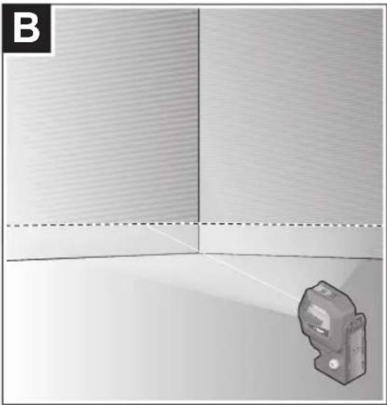
natural_image
Diagram showing a 3D object with a laser beam interacting with a panel, labeled 'B' in the top-left corner (no text or symbols on the diagram itself)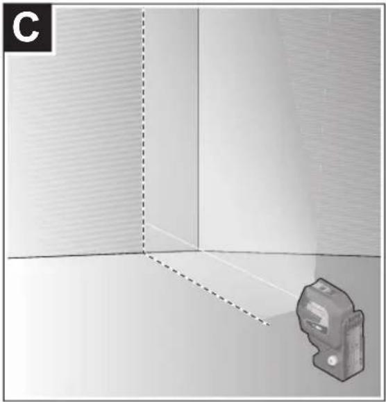
natural_image
Diagram showing a 3D object with a dashed line and label 'C' in the corner, no readable text or symbols present.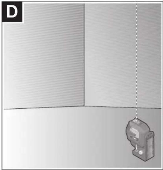
natural_image
Diagram showing a mechanical device suspended from a vertical wall, with no visible text or symbols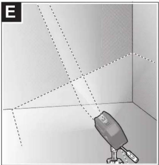
natural_image
3D diagram of a camera setup with dashed lines and a labeled 'E' in the corner (no text or symbols on the diagram itself)1 609 92A 5EN | (20.03.2020) Bosch Power Tools
5
natural_image
3D rendered image of a mechanical device with no visible text or symbols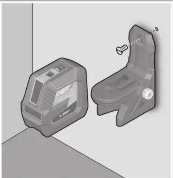
natural_image
3D rendering of two mechanical components: a rectangular device and a toilet, both without any visible text or symbols.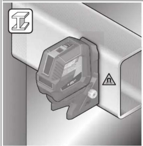
natural_image
Close-up of a mechanical device with a warning symbol (no readable text or labels)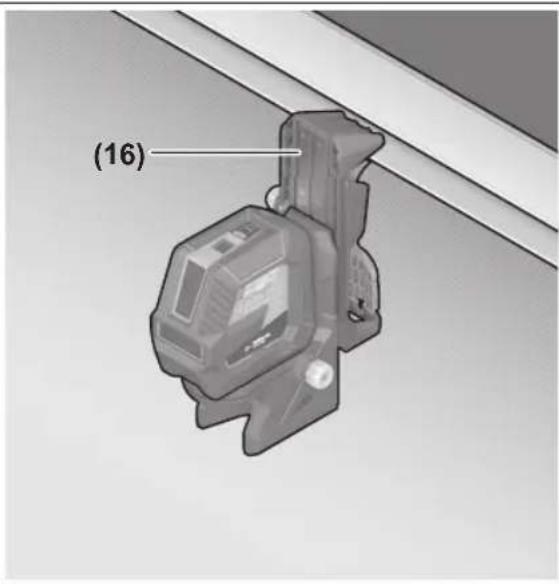
6
natural_image
Diagram of a 3D room setup with a camera on a tripod, showing walls and a wall-mounted unit (no text or symbols)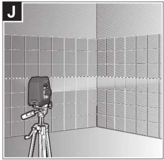
natural_image
Illustration of a camera on a tripod in a tiled room, no text or symbols present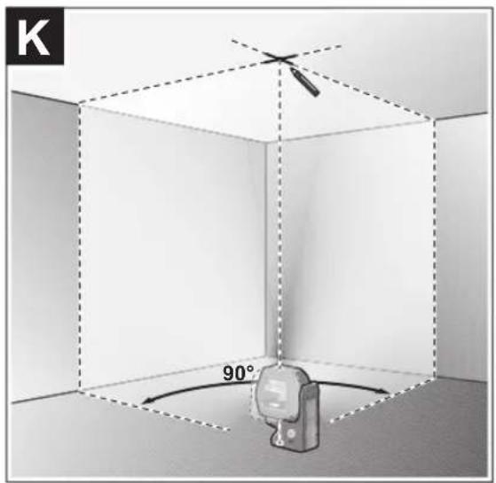
natural_image
Interior corner view of a room with a wall-mounted device and a ceiling-mounted sensor (no text or symbols visible)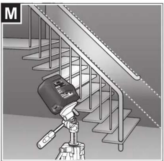
natural_image
Illustration of a camera mounted on a tripod next to a staircase with metal railings (no text or symbols)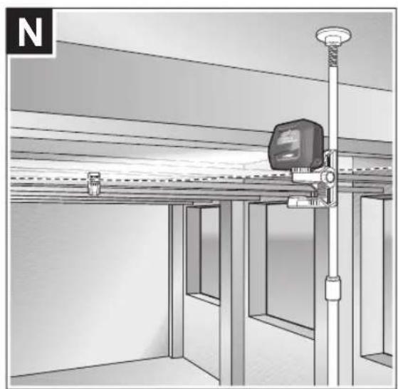
natural_image
Interior view of a modern building with overhead lighting and a mounted TV (no visible text or symbols)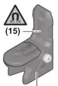
(11)
RM 10
0 601 092 A00
(17)
BM 1
0 601 015 A01
(19)
LR 7
0 601 069 J00

(15)
(20)
natural_image
Technical line drawing of a tripod with adjustable legs and a top-mounted device (no text or symbols)(21)
BT 150
0 601 096 B00

(23)
1 608 M00 05J
(24)
Deutsch
Sicherheitshinweise

All instructions must be read and observed in order for the measuring tool to function safely. The safeguards integrated into the measuring tool may be compromised if the measuring tool is not used in accordance with these instructions. Never make warning signs on the measuring tool unrecognisable. SAVE THESE INSTRUCTIONS FOR FUTURE REFERENCE AND INCLUDE THEM WITH THE MEASURING TOOL WHEN TRANSFERRING IT TO A THIRD PARTY.
▶ Warning! If operating or adjustment devices other than those specified here are used or other procedures are carried out, this can lead to dangerous exposure to radiation.
The measuring tool is delivered with a laser warning sign (marked in the illustration of the measuring tool on the graphics page).
If the text of the laser warning label is not in your national language, stick the provided warning label in your national language over it before operating for the first time.

Do not direct the laser beam at persons or animals and do not stare into the direct or reflected laser beam yourself. You could blind somebody, cause accidents or damage your eyes.
▶ If laser radiation hits your eye, you must close your eyes and immediately turn your head away from the beam.
▶ Do not make any modifications to the laser equipment.
▶ Do not use the laser goggles as protective goggles. The laser goggles make the laser beam easier to see; they do not protect you against laser radiation.
▶ Do not use the laser goggles as sunglasses or while driving. The laser goggles do not provide full UV protection and impair your ability to see colours.
▶ Have the measuring tool serviced only by a qualified specialist using only original replacement parts. This will ensure that the safety of the measuring tool is maintained.
▶ Do not let children use the laser measuring tool unsupervised. They could accidentally dazzle someone.
▶ Do not use the measuring tool in explosive atmospheres which contain flammable liquids, gases or dust. Sparks may be produced inside the measuring tool, which can ignite dust or fumes.

Keep the magnetic accessories away from implants and other medical devices, e.g. pacemakers or insulin pumps. The magnets in the accessories generate a field that can im-
pair the function of implants and medical devices.
▶ Keep the magnetic accessories away from magnetic data storage media and magnetically-sensitive devices. The effect of the magnets in the accessories can lead to irreversible data loss.
Product Description and Specifications
Please observe the illustrations at the beginning of this operating manual.
Intended Use
The measuring tool is intended for determining and checking horizontal and vertical lines and plumb points.
The measuring tool is suitable for indoor and outdoor use.
Product Features
The numbering of the product features shown refers to the illustration of the measuring tool on the graphic page.
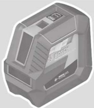
(1) Laser beam outlet aperture
(2) Battery indicator
(3) Button for laser operating mode
(4) On/off switch
(5) 1/4" tripod mount
(6) Guide groove
(7) Battery compartment cover locking mechanism
(8) Battery compartment cover
(9) Laser warning label
(10) Serial number
(11) Rotating mount (RM 10) ^A)
(12) Guide rail
(13) Fastening slot
(14) Fine adjustment screw of the rotating mount
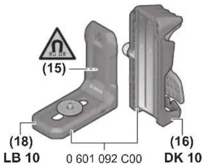
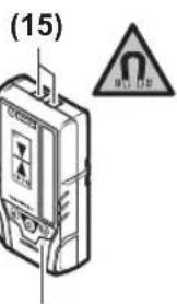
(15) Magnet
(16) Ceiling clip (DK 10) ^A)
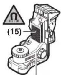
(17) Universal holder (BM 1) ^4
(18) Holder (LB 10) ^A)
(19) Laser receiver ^4
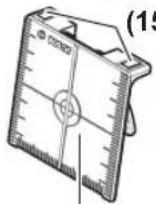
(20) Laser target plate ^A)
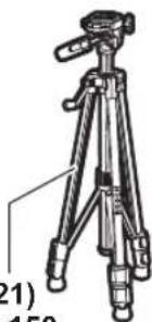
(21) Tripod (BT 150) ^A
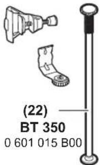
(22) Telescopic shaft (BT 350) ^A)
(23) Laser goggles ^A)
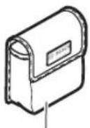
(24) Protective bag ^A
A) Accessories shown or described are not included with the product as standard. You can find the complete selection of accessories in our accessories range.
16 | English
Technical Data
| Point and line laser GCL 2-50 G | |
| Article number | 3 601 K66 M.. |
| Working rangeA) | |
| - Standard laser lines 15 m | |
| - Laser lines with laser receiver | 5-50 m |
| - Laser points 10 m | |
| Levelling accuracyB)(C) | |
| - Laser lines ±0.3 mm/m | |
| - Laser points ±0.7 mm/m | |
| Self-levelling range ±4° | |
| Levelling time < 4 s | |
| Operating temperature -10 °C to +45 °C | |
| Storage temperature -20 °C to +70 °C | |
| Max. altitude 2000 m | |
| Relative air humidity max. 90% | |
| Pollution degree according to IEC 61010-1 | 2D) |
| Laser class 2 | |
| Laser lines | |
| - Laser type 500-540 nm, < 10 mW | |
| - C6 | 10 |
| - Divergence 50 × 10 mrad (full angle) | |
| Laser points | |
| - Laser type 500-540 nm, < 1 mW | |
| - C6 | 1 |
| - Divergence | 0.8 mrad (full angle) |
| Compatible laser receiver | LR 7 |
| Tripod mount | 1/4" |
| Batteries 4 × 1.5 V LR6 (AA) | |
| Weight according to EPTA-Procedure 01:2014 | 0.58 kg |
| Dimensions (length × width × height) | |
| - Without holder | 126 × 63 × 115 mm |
| - With rotating mount RM 10 | 145 × 63 × 180 mm |
| Protection rating | IP 64 |
A) The working range may be reduced by unfavourable environmental conditions (e.g. direct sunlight).
B) At 20-25°C
C) The values stated presuppose normal to favourable environmental conditions (e.g. no vibration, no fog, no smoke, no direct sunlight). Extreme fluctuations in temperature can cause deviations in accuracy.
D) Only non-conductive deposits occur, whereby occasional temporary conductivity caused by condensation is expected.
The serial number (10) on the type plate is used to clearly identify your measuring tool.
Assembly
Inserting/Changing the batteries
It is recommended that you use alkaline manganese batteries to operate the measuring tool.
Press the locking mechanism (7) upwards to open the battery compartment cover (8) and remove the battery compartment cover. Insert the batteries.
When inserting the batteries, ensure that the polarity is correct according to the illustration on the inside of the battery compartment.
The battery indicator (2) always indicates the current status of the battery.
If the batteries are running low, the laser lines will gradually become dimmer.
If the batteries are almost empty, the battery indicator (2) will flash continuously. The laser lines will flash for 5 seconds every 5 minutes.
If the batteries are empty, the laser lines and the battery indicator will flash once before the measuring tool switches off.
Always replace all the batteries at the same time. Only use batteries from the same manufacturer and which have the same capacity.
▶ Take the batteries out of the measuring tool when you are not using it for a prolonged period of time. The batteries can corrode and self-discharge during prolonged storage in the measuring tool.
Operation
Starting Operation
▶ Protect the measuring tool from moisture and direct sunlight.
▶ Do not expose the measuring tool to any extreme temperatures or fluctuations in temperature. For example, do not leave it in a car for extended periods of time. If it has been subjected to significant fluctuations in temperature, first allow the measuring tool to adjust to the ambient temperature and then always carry out an accuracy check before continuing work (see "Accuracy Check of the Measuring Tool", page 17).
The precision of the measuring tool may be compromised if exposed to extreme temperatures or fluctuations in temperature.
▶ Avoid substantial knocks to the measuring tool and avoid dropping it. Always carry out an accuracy check before continuing work if the measuring tool has been subjected to severe external influences (see "Accuracy Check of the Measuring Tool", page 17).
▶ Switch the measuring tool off when transporting it.
The pendulum unit is locked when the tool is switched off, as it can otherwise be damaged by big movements.
Switching On/Off
To switch on the measuring tool, slide the on/off switch (4) to the "On" position. As soon as it is switched on, the measuring tool emits laser beams from the outlet apertures (1).
▶ Do not direct the laser beam at persons or animals and do not stare into the laser beam yourself (even from a distance).
The measuring tool can be used with a laser receiver (19) at any time.
To switch off the measuring tool, slide the on/off switch (4) to the Off position. The pendulum unit is locked when the tool is switched off.
▶ Never leave the measuring tool unattended when switched on, and ensure the measuring tool is switched off after use. Others may be blinded by the laser beam.
If the maximum permitted operating temperature of 45^ C is exceeded, the tool shuts down to protect the laser diode. Once it has cooled down, the measuring tool is operational again and can be switched back on.
Automatic shut-off
If no button on the measuring tool is pressed for approx. 120 min, the measuring tool will automatically switch itself off to preserve battery life.
To switch the measuring tool back on after it has been automatically switched off, you can either slide the on/off switch (4) to the "Off" position first and then switch the measuring tool back on, or press the laser operating mode button (3).
To deactivate the automatic shut-off function, hold down the laser mode button (3) for at least 3 s (with the measuring tool switched on). If the automatic shut-off function is deactivated, the laser beams will flash briefly as confirmation.
Note: If the operating temperature exceeds 45 °C, automatic shut-off can no longer be deactivated.
To activate the automatic shut-off function, switch the measuring tool off and on again.
Operating Modes
The measuring tool has several operating modes, which you can switch between at any time:
- Cross-line and point mode (see figure A): The measuring tool generates a horizontal and a vertical laser line facing forwards as well as two vertical laser points – one facing up, the other down.
- Horizontal operation (see figure B): The measuring tool generates a horizontal laser line.
- Vertical operation (see figure C): The measuring tool generates a vertical laser line. If the measuring tool is positioned in the room, the vertical laser line is displayed on the ceiling beyond the upper laser point.
- Point mode: (see figure D): The measuring tool generates two vertical laser points – one facing up, the other down.
To change the operating mode, press the button for laser operating mode (3) as often as required until the laser beams are generated in the required operating mode.
All operating modes can be used with both automatic leveling and the incline function.
All operating modes are suitable for operation with the laser receiver (19).
Automatic Levelling
The measuring tool monitors the position at all times during operation. It works with automatic levelling during set-up within the self-levelling range of ±4^ . Outside of the self-levelling range, it will automatically switch to the incline function.
Working with automatic levelling (see figures A-D)
Position the measuring tool on a level, firm surface or attach it to the rotating mount (11) or the tripod (21).
The automatic levelling function automatically compensates irregularities within the self-levelling range of ±4^ . Once the laser beam is permanently lit, the measuring tool has levelled in.
If automatic levelling is not possible, e.g. because the surface on which the measuring tool stands deviates by more than 4^ from the horizontal plane, the laser lines will initially flash quickly for 2 seconds, then quickly flash every 5 seconds several times. The measuring tool is in the incline function.
For additional work with automatic levelling, set up the measuring tool so that it is horizontal and wait for the self-levelling procedure to complete. As soon as the measuring tool is within the self-levelling range of ±4^ , the laser beams will light up continuously.
In case of ground vibrations or position changes during operation, the measuring tool is automatically levelled again.
Upon levelling, check the position of the laser beams with regard to the reference points to avoid errors arising from a change in the measuring tool's position.
Working with the Incline Function (see figure E)
Place the measuring tool on an inclined surface. When working with the incline function, the laser lines will initially flash quickly for 2 seconds, then quickly flash every 5 seconds several times.
In the incline function, the laser lines are no longer levelled and no longer necessarily run perpendicular to one another.
Accuracy Check of the Measuring Tool
Influences on Accuracy
The largest influence is exerted by the ambient temperature. In particular, temperature differences that occur from the ground upwards can refract the laser beam.
Since the temperature stratification is greatest at ground level, you should always mount the measuring tool on a tripod for measuring distances of 20 m or more. In addition, position the measuring tool in the centre of the work surface, wherever this is possible.
18 | English
In addition to external influences, device-specific influences (e.g. falls or heavy impacts) can also lead to deviations. For this reason, check the levelling accuracy each time before beginning work.
First check the height accuracy and levelling accuracy of the horizontal laser line, then the levelling accuracy of the vertical laser line.
Should the measuring tool exceed the maximum deviation during one of the tests, please have it repaired by a Bosch after-sales service.
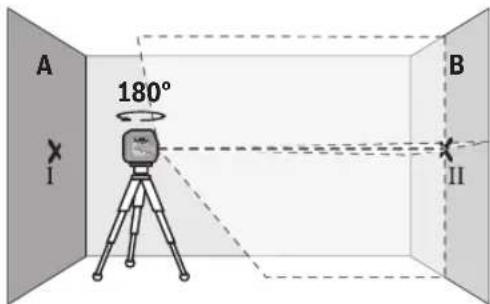
Checking the Height Accuracy of the Horizontal Line
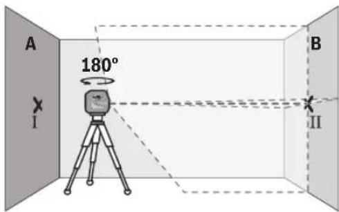
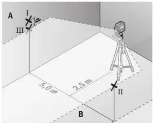
For this check, you will need a free measuring distance of 5 m on firm ground between two walls (designated A and B).
- Mount the measuring tool close to wall A on a tripod, or place it on a firm, level surface. Switch on the measuring tool and select cross-line operation.
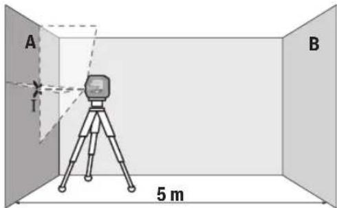
- Aim the laser at the closer wall A and allow the measuring tool to level in. Mark the middle of the point at which the laser lines cross on the wall (point I).
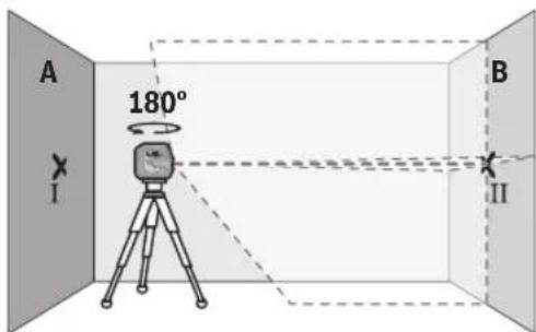
- Turn the measuring tool 180^ , allow it to level in and mark the point where the laser lines cross on the opposite wall B (point II).
- Position the measuring tool – without rotating it – close to wall B, switch it on and allow it to level in.
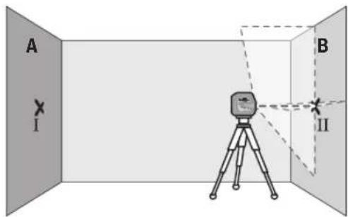
- Align the height of the measuring tool (using the tripod or by placing objects underneath as required) so that the point where the laser lines cross exactly hits the previously marked point II on wall B.
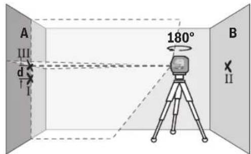
- Turn the measuring tool 180^ without adjusting the height. Aim it at wall A such that the vertical laser line runs through the already marked point I. Allow the measuring tool to level in and mark the point where the laser lines cross on wall A (point III).
- The discrepancy d between the two marked points I and III on wall A reveals the actual height deviation of the measuring tool.
The maximum permitted deviation on the measuring distance of 2 × 5 m = 10 m is as follows:
10 m × ±0.3 mm/m = ±3 mm. The discrepancy d between points I and III must therefore amount to no more than 3 mm.
Checking the Level Accuracy of the Horizontal Line
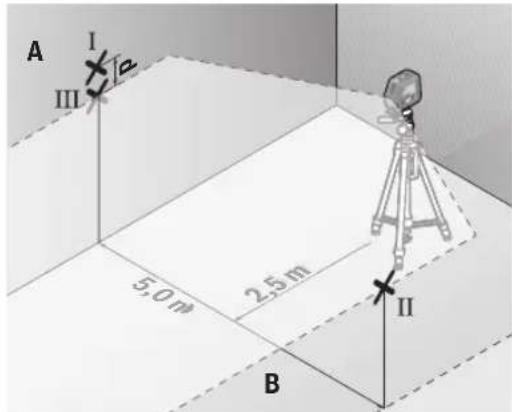
For this check, you will need a free area of 5 × 5 m.
- Mount the measuring tool in the middle between walls A and B on a tripod, or place it on a firm, level surface. Switch on the measuring tool and select horizontal operation. Allow the measuring tool to level in.
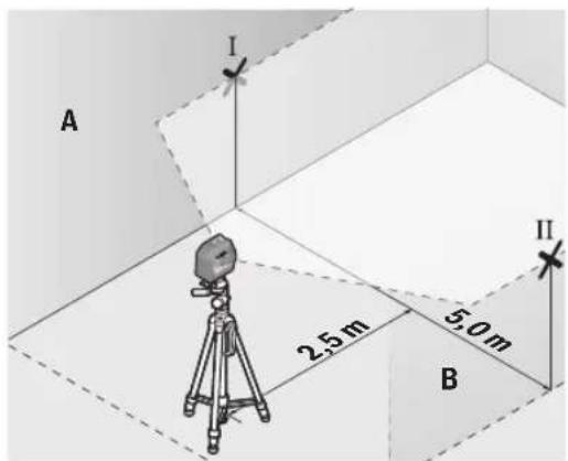
- At a distance of 2.5 m from the measuring tool, mark the centre of the laser line on both walls (point I on wall A and point II on wall B).
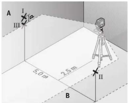
- Set up the measuring tool at a 5 m distance and rotated by 180^ and allow it to level in.
- Align the height of the measuring tool (using the tripod or by placing objects underneath as required) so that the centre of the laser line exactly hits the previously marked point II on wall B.
- Mark the centre of the laser line on wall A as point III (vertically above or below point I).
- The discrepancy d between the two marked points I and III on wall A reveals the actual horizontal deviation of the measuring tool.
The maximum permitted deviation on the measuring distance of 2 × 5 m = 10 m is as follows:
10 m × ±0.3 mm/m = ±3 mm. The discrepancy d between points I and III must therefore amount to no more than 3 mm.
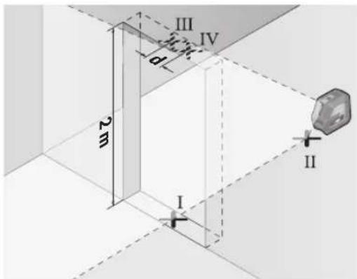
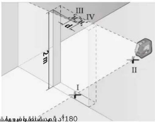
Checking the Level Accuracy of the Vertical Line
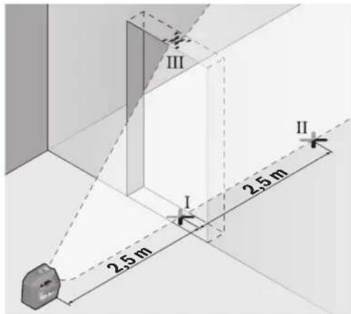
For this check, you will need a door opening (on solid ground) which has at least 2.5 m of space either side of the door.
- Place the measuring tool 2.5 m away from the door opening on a firm, flat surface (not on a tripod). Switch on the measuring tool and select vertical operation. Aim the
laser line at the door opening and allow the measuring tool to level in.
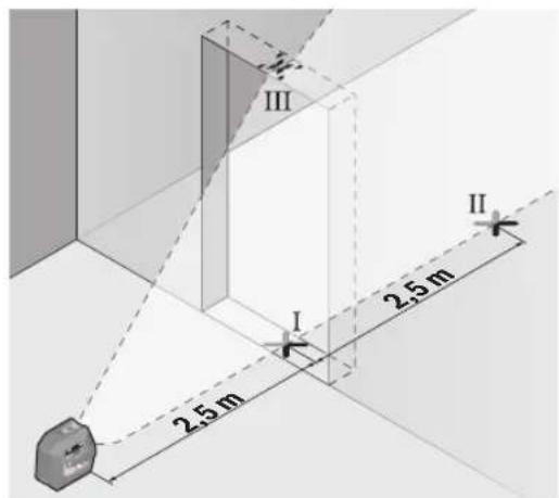
- Mark the centre of the vertical laser line on the floor of the door opening (point I), 5 m away on the other side of the door opening (point II) and on the upper edge of the door opening (point III).
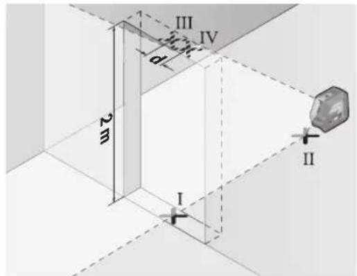
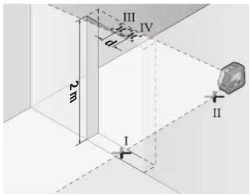
- Rotate the measuring tool 180^ and position it on the other side of the door opening, directly behind point II. Allow the measuring tool to level in and align the vertical laser line in such a way that its centre passes through points I and II exactly.
- Mark the centre of the laser line on the upper edge of the door opening as point IV.
- The discrepancy d between the two marked points III and IV reveals the actual vertical deviation of the measuring tool.
- Measure the height of the door opening. You can calculate the maximum permitted deviation as follows:
Doubled height of the door opening × 0.3 mm/m Example: At a door opening height of 2 m, the maximum deviation amounts to
2 × 2 m × ± 0.3 mm/m = ± 1.2 mm . The points III and IV must therefore be no further than 1.2 mm from each other.
20 | English
Checking Plumb Accuracy
For this check, you will need a clear measuring space on firm ground with a distance of approx. 5 m between the floor and the ceiling.
- Mount the measuring tool onto the rotating mount (11) and place it on the floor. Select point mode and allow the measuring tool to level in.
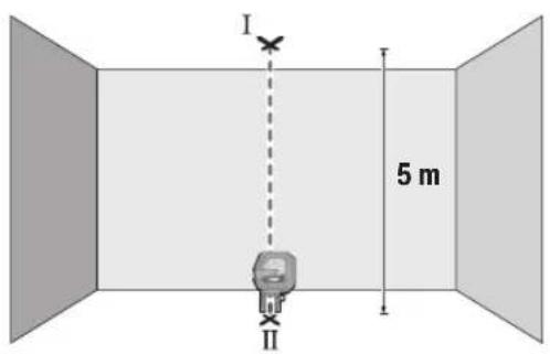
- Mark the centre of the top laser point on the ceiling (point I). Also mark the centre of the bottom laser point on the floor (point II).
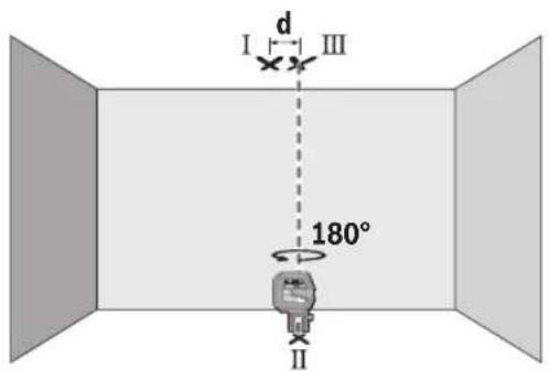
- Turn the measuring tool by 180^ . Position it so that the centre of the bottom laser point falls onto the marked point II. Allow the measuring tool to level in. Mark the centre of the top laser point (point III).
- The discrepancy d between the two marked points I and III on the ceiling reveals the actual deviation of the measuring tool from the vertical plane.
You can calculate the maximum permitted deviation as follows:
Doubled distance between floor and ceiling × 0.7 mm/m Example: At a floor-to-ceiling distance of 5 m, the maximum deviation amounts to
2 × 5 m × ± 0.7 mm/m = ± 7 mm . The points I and III must therefore be no further than 7 mm from each other.
Working Advice
▶ Only the centre of the laser point or laser line must be used for marking. The size of the laser point/the width of the laser line changes depending on the distance.
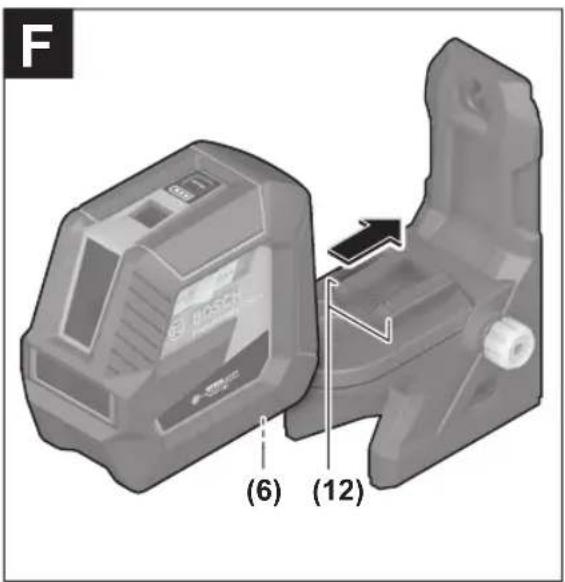
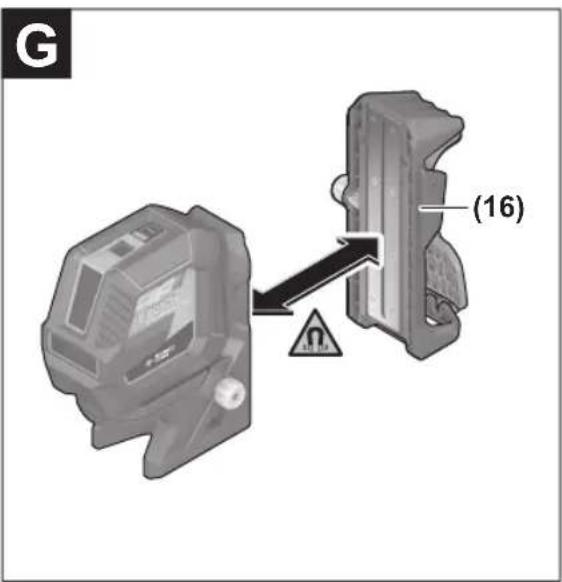
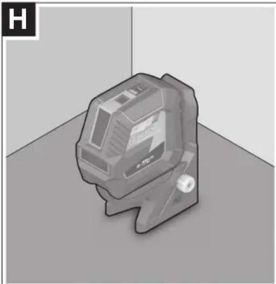
Working with the RM 10 Rotating Mount (see figures F-H)
You can use the rotating mount (11) to rotate the measuring tool 360° around a central, always visible plumb point. This enables you to set up the laser lines without having to change the position of the measuring tool.
You can use the fine adjustment screw (14) to align vertical laser lines precisely with reference points.
Place the measuring tool with the guide groove (6) on the guide rail (12) of the rotating mount (11) and slide the measuring tool all the way onto the platform.
To disconnect the measuring tool, pull it off the rotating mount in the opposite direction.
Positioning possibilities of the rotating mount:
- Standing on a flat surface,
- Screwed to a vertical surface,
- On metallic surfaces using the magnets (15),
- On crown moulding using the ceiling clip (16).
Roughly align the rotating mount (11) before switching on the measuring tool.
Working with the Laser Target Plate
The laser target plate (20) improves visibility of the laser beam in unfavourable conditions and at greater distances.
The reflective half of the laser target plate (20) improves visibility of the laser line. The transparent half enables the laser line to be seen from behind the laser target plate.
Working with the Tripod (Accessory)
A tripod offers a stable, height-adjustable support surface for measuring. Place the measuring tool with the 1/4" tripod mount (5) on the thread of the tripod (21) or a conventional camera tripod. Tighten the measuring tool using the locking screw of the tripod.
Roughly align the tripod before switching on the measuring tool.
Securing with the universal holder (accessory) (see figure N)
Using the universal holder (17), you can secure the measuring tool on vertical surfaces, pipes or magnetizable materials, for example. The universal holder is also suitable for use as a building tripod and facilitates height adjustment of the measuring tool.
Roughly align the universal holder (17) before switching on the measuring tool.
Working with the Holder LB 10 (accessory)
You can secure the measuring tool on vertical surfaces or magnetisable materials using the holder (18). In conjunction with the ceiling clip (16), the measuring tool can also be aligned vertically.
Roughly align the holder (18) before switching on the measuring tool.
Working with the Laser Receiver (accessory) (see figure N)
Use the laser receiver (19) to improve detection of the laser lines in adverse lighting conditions (bright environment, direct sunlight) and over greater distances.
All operating modes are suitable for operation with the laser receiver (19).
Laser Goggles (Accessory)
The laser goggles filter out ambient light. This makes the light of the laser appear brighter to the eye.
▶ Do not use the laser goggles as protective goggles.
The laser goggles make the laser beam easier to see; they do not protect you against laser radiation.
▶ Do not use the laser goggles as sunglasses or while driving. The laser goggles do not provide full UV protection and impair your ability to see colours.
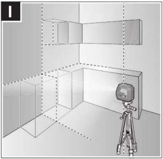
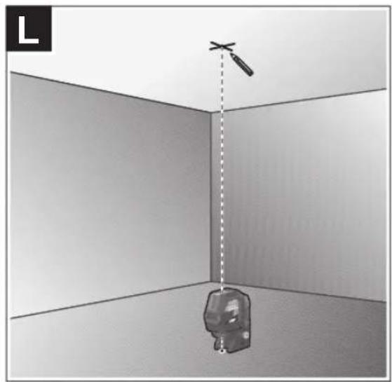
Example applications (see figures I–N)
Examples of possible applications for the measuring tool can be found on the graphics pages.
Maintenance and Service
Maintenance and Cleaning
Keep the measuring tool clean at all times.
Never immerse the measuring tool in water or other liquids.
Wipe off any dirt using a damp, soft cloth. Do not use any detergents or solvents.
The areas around the outlet aperture of the laser in particular should be cleaned on a regular basis. Make sure to check for lint when doing this.
Only store and transport the measuring tool in the protective pouch (24).
If the measuring tool needs to be repaired, send it off in the protective pouch (24).
After-Sales Service and Application Service
Our after-sales service responds to your questions concerning maintenance and repair of your product as well as spare parts. You can find explosion drawings and information on spare parts at: www.bosch-pt.com
The Bosch product use advice team will be happy to help you with any questions about our products and their accessories.
In all correspondence and spare parts orders, please always include the 10-digit article number given on the nameplate of the product.
Cambodia
Robert Bosch (Cambodia) Co., Ltd
Unit 8BC, GT Tower, 08th Floor, Street 169,
Czechoslovakia Blvd, Sangkat Veal Vong
Khan 7 Makara, Phnom Penh
VAT TIN: 100 169 511
Tel.: +855 23 900 685
Tel.: +855 23 900 660
www.bosch.com.kh
People's Republic of China
China Mainland
Bosch Power Tool (China) Co. Ltd.
Bosch Service Center
567, Bin Kang Road
Bin Kang District
Hangzhou, Zhejiang Province
China 310052
Tel.: (0571) 8887 5566 / 5588
Fax: (0571) 8887 6688 x 5566# / 5588#
E-Mail: bsc.hz@cn.bosch.com
www.bosch-pt.com.cn
HK and Macau Special Administrative Regions
Robert Bosch Co. Ltd.
21st Floor, 625 King's Road
North Point, Hong Kong
Customer Service Hotline: +852 2101 0235
Fax: +852 2590 9762
E-Mail: info@hk.bosch.com
www.bosch-pt.com.hk
India
Bosch Service Center
69, Habibullah Road, (Next to PSBB School), T. Nagar
Chennai-600077
Phone: (044) 64561816
Bosch Service Center
18, Community Center
Phase 1, Mayapuri
New Delhi-110064
Phone: (011) 43166190
Indonesia
PT Robert Bosch
Palma Tower 10th Floor
Jalan RA Kartini II-S Kaveling 6
Pondok Pinang, Kebayoran Lama
Robert Bosch Middle East FZE - Pakistan Liaison Office
2nd Floor Plaza # 10, CCA Block, DHA Phase 5
Lahore, 54810
Phone: +92(303)4444311
Email: Faisal.Khan@bosch.com
22 | English
Philippines
Robert Bosch, Inc.
11th Floor Ten West Campus
20 LeGrand Ave., McKinley West
Fort Bonifacio, Taguig City 1634
Tel.: (+632) 8703871
www.bosch-pt.com.ph
Singapore
Powerwell Service Centre Ptd Ltd
Bosch Authorised Service Centre (Power Tools)
4012 Ang Mo Kio Ave 10, #01-02 TECHplace
Singapore 569628
Tel.: 6452 1770
Fax: 6452 1760
E-Mail: ask@powerwellsc.com
www.powerwellsc.com
www.bosch-pt.com.sg
Thailand
Robert Bosch Ltd.
FYI Center Tower 1, 5th Floor.
2525 Rama IV Road, Klongtoei,
Bangkok 10110
Tel.: 02 0128888
Fax: 02 0645802
www.bosch.co.th
Bosch Service – Training Centre
La Salle Tower Ground Floor Unit No.2
10/11 La Salle Moo 16
Srinakharin Road
Bangkaew, Bang Plee
Samutprakarn 10540
Tel.: 02 7587555
Fax: 02 7587525
Vietnam
Branch of Bosch Vietnam Co., Ltd in HCMC
14th floor, Deutsches Haus, 33 Le Duan
Ben Nghe Ward, District 1, Ho Chi Minh City
Tel.: (028) 6258 3690
Fax: (028) 6258 3692 - 6258 3694
Hotline: (028) 6250 8555
Email: tuvankhachhang-pt@vn.bosch.com
www.bosch-pt.com.vn
Bahrain
EA Juffali and Brothers for Technical Equipment Company.
Kingdom of Bahrain, Al Aker - Block 0624 - Road 2403 -
Building 0055D
Phone: +97317704537
Fax: +973177045257
Email: h.berjas@eajb.com.sa
Egypt
RBEG-LLC
22 Kamal Eldin Hussein
Sheraton Heliopolis
11799 Cairo
E-mail: boschegypt.powertools@eg.bosch.com
Iran
Robert Bosch Iran
3rd Floor, No 3, Maadiran Building
Aftab St., Khodami St., Vanak Sq.
Tehran 1994834571
Phone: +9821-86092057
Iraq
Sahba Technology Group
Al Muthana airport road
Baghdad
Phone Bagdad: +964 (0) 7 901 930366
Phone Dubai: +971 (0) 4 422 1898
Email: duraid@sahbatechnology.com
Jordan
Roots Arabia - Jordan
Al-Hurriyah Street, Al-Muqabalein
Amman 11623, Jordan
P.O. Box: 110068
Tel.: +962 6 4398990
E-mail: bosch@rootsjordan.com
Kuwait
Shuwaikh Industrial Area, Block 1, Plot 16, Street 3rd
P.O. Box 164 - Safat 13002
Phone: +965 - 2496 88 88
Fax: +965 - 2481 08 79
E-mail: josephkr@aaalmutawa.com
Lebanon
Tehini Hana & Co. S.A.R.L.
P.O. Box 90-449
Jdeideh 1202 2040
Dora-Beirut
Phone: +9611255211
Email: service-pt@tehini-hana.com
Libya
El Naser for Workshop Tools
Swanee Road, Alfalah Area
Tripoli
Phone: +218 21 4811184
Oman
Malatan Trading & Contracting LLC
P.O. Box 131, Ruwi, Muscat
Postal Code: 112, Sultanate of Oman
Phone: +968 2479 4035/4089/4901
Mob: +968-91315465
Fax: +968 2479 4058
E-Mail: sudhirkumar@malatan.net
Qatar
International Construction Solutions W L L
P. O. Box 51, Doha
Phone: +974 40065458
Fax: +974 4453 8585
Email: csd@icsdoha.com
Saudi Arabia
Juffali Technical Equipment Co. (JTECO)
P.O.Box: 1049 - Jeddah 21431 - KSA
Jeddah: 00966 (0) 12 692 0770 - Ext 433
Riyadh: 00966 (0) 11 409 3976 - Ext-30/34/39
Dammam: 00966 (0) 13 833 9565
E-mail: M.Zreik@eajb.com.sa
Syria
Dallal Establishment for Power Tools
Damascus. Baramkeh street - Ibn Amer street,
Phone: +963112241006 or 009631122414009
Mobile: 00963991141005
Email: rita.dallal@hotmail.com
United Arab Emirates
Central Motors & Equipment,
P.O. Box 26255, Dubai
Dubai: 00971 (0) 4 3090920/3090930
Abu Dhabi: 00971 (0) 2 4017745
Sharjah: 00971 (0) 6 5932777
Al Ain: 00971 (0) 3 7157419
E-Mail: Mallappa.Madari@centralmotors.ae
Yemen
Abu Alrejal Trading Corporation
P.O. Box: 17024, Zubeiry St.
Sana'a, Yemen
Tel: +967-1-20 20 10
Fax: +967-1-47 19 17
E-mail: tech-tools@abualrejal.com/yahya@abualrejal.com
Ethiopia
Forever plc
Kebele 2,754, BP 4806,
Addis Ababa
Phone: +251 111 560 600
Email: foreverplc@ethionet.et
Ghana
Robert Bosch Ghana Limited
21 Kofi Annan Road Airport Residential Area Accra
Tel. +233 (0)3027 94616
Kenya
Robert Bosch East Africa Ltd
Mpaka Road P.O. Box 856
00606 Nairobi
Nigeria
Robert Bosch Nigeria Ltd.
52-54 Isaac John Street P.O. Box
GRA Ikeja - Lagos
Tanzania
Diesel & Autoelectric Service Ltd.
117 Nyerere Rd., P.O. Box 70839
Vingunguti 12109, Dar Es Salaam
Phone: +255 222 861 793/794
Australia, New Zealand and Pacific Islands
Robert Bosch Australia Pty. Ltd.
Power Tools
Locked Bag 66
Clayton South VIC 3169
Customer Contact Center
Inside Australia:
Phone: (01300) 307044
Fax: (01300) 307045
Inside New Zealand:
Phone: (0800) 543353
Fax: (0800) 428570
Outside AU and NZ:
Phone: +61 3 95415555
www.bosch-pt.com.au
www.bosch-pt.co.nz
Myanmar
Asia Era Company Limited
No.(40/44), Parami Road, 4th Quarter, South Okkalapa Tsp,
Yangon, Myanmar
Great Britain
Robert Bosch Ltd. (B.S.C.)
P.O. Box 98
Broadwater Park
North Orbital Road
Denham Uxbridge
UB 9 5HJ
At www.bosch-pt.co.uk you can order spare parts or arrange
the collection of a product in need of servicing or repair.
Tel. Service: (0344) 7360109
E-Mail: boschservicecentre@bosch.com
Ireland
Origo Ltd.
Unit 23 Magna Drive
Magna Business Park
City West
Dublin 24
Tel. Service: (01) 4666700
Fax: (01) 4666888
Republic of South Africa
Customer service
Hotline: (011) 6519600
Gauteng - BSC Service Centre
35 Roper Street, New Centre
Johannesburg
Tel.: (011) 4939375
Fax: (011) 4930126
E-Mail: bsctools@icon.co.za
KZN - BSC Service Centre
Unit E, Almar Centre
143 Crompton Street
Pinetown
Tel.: (031) 7012120
Fax: (031) 7012446
E-Mail: bsc.dur@za.bosch.com
Western Cape - BSC Service Centre
Democracy Way, Prosperity Park
Milnerton
Tel.: (021) 5512577
Fax: (021) 5513223
E-Mail: bsc@zsd.co.za
Bosch Headquarters
Midrand, Gauteng
24 | Français
Tel.: (011) 6519600
Fax: (011) 6519880
E-Mail: rbsa-hq.pts@za.bosch.com
Armenia, Azerbaijan, Georgia
Robert Bosch Ltd.
David Agmashenebeli ave. 61
0102 Tbilisi, Georgia
Tel. +995322510073
www.bosch.com
Kyrgyzstan, Mongolia, Tajikistan, Turkmenistan, Uzbekistan
TOO "Robert Bosch" Power Tools, After Sales Service
Muratbaev Ave., 180
050012, Almaty, Kazakhstan
Service Email: service.pt.ka@bosch.com
Official Website: www.bosch.com, www.bosch-pt.com
Disposal
Measuring tools, accessories and packaging should be recycled in an environmentally friendly manner.

Do not dispose of measuring tools or batteries with household waste.
Only for EU countries:
According to the Directive 2012/19/EU, measuring tools that are no longer usable, and according to the Directive 2006/66/EC, defective or used battery packs/batteries, must be collected separately and disposed of in an environmentally correct manner.
Français
(17) Support universel (BM 1) ^4
(18) Support (LB 10) ^A
Robert Bosch Morocco SARL
53, Rue Lieutenant Mahroud Mohamed
20300 Casablanca
Tel.: +212 5 29 31 43 27
E-Mail:sav.outillage@ma.bosch.com
Tunisie
Robert Bosch Tunisie SARL
Robert Bosch (France) S.A.S.
Robert Bosch Argentina Industrial S.A.
Calle Blanco Encalada 250 - San Isidro
B1642AMQ
Calle Robert Bosch No. 405
Bosch Service Center
Telegrafvej 3
2750 Ballerup
På www.bosch-pt.dk kan der online bestilles reservedele eller oprettes en reparations ordre.
Tlf. Service Center: 44898855
Fax: 44898755
E-Mail: vaerktoej@dk.bosch.com
Bortskaffelse
Bosch Service Center
Telegrafvej 3
2750 Ballerup
Danmark
Tel.: (08) 7501820 (inom Sverige)
Fax: (011) 187691
Avfallshantering
Robert Bosch Sp. z o.o.
Bosch Service Center PT
K Vápence 1621/16
692 01 Mikulov
118 | Slovenčina
Service scule electrice
Strada Horia Măcelariu Nr. 30-34, sector 1
013937 Bucureşti
Service scule electrice
Strada Horia Măcelariu Nr. 30-34, sector 1
013937 Bucureşti, România
www.bosch-pt.com/bg/bg/
Бракуване
- Usmerite laser na bliski zid A i pustite da se merni alat niveliše. Označite sredinu tačke na kojoj se laserske linije na zidu ukrštaju (tačka I).
174 | Srpski
- Okrenite merni alat za 180°, pustite da se niveliše i označite tačku ukrštanja laserskih linija na suprotnom zidu B (tačka II).
- Stavite merni alat - bez okretanja - blizu zida B, uključite ga i pustite da se niveliše.
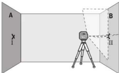
- Merni alat usmerite u vis tako (pomoću stativa ili po potrebi podmetanjem), da tačka ukrštanja laserskih linija tačno pogada prethodno označenu tačku II na zidu B.
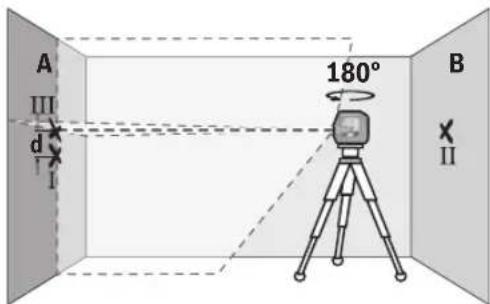
- Merni alat okrenite za 180°, a da ne pomerate visinu. Usmerite ga prema zidu A, tako da vertikalna laserska linija prolazi kroz već označenu tačku I. Pustite merni alat da se niveliše i označite tačku ukrštanja laserskih linija na zidu A (tačka III).
- Razlika d između dve označene tačke I i III na zidu A predstavlja stvarno odstupanje visine mernog alata. Na mernoj deonici od 2 × 5 m = 10 m maksimalno dozvoljeno odstupanje iznosi: 10 m × ±0,3 mm/m = ±3 mm. Razlika d između tačaka I i III sme da iznosi maksimalno 3 mm.
Provera preciznosti nivelacije horizontalne linije
Za proveru je neophodna slobodna površina od otprilike 5 × 5 m.
- Montirajte merni alat u sredini između zidova A i B na stativ, ili ga postavite na čvrstu ravnu podlogu. Uključite merni alat i izaberite horizontalni režim rada. Pustite da se merni alat izniveliše.
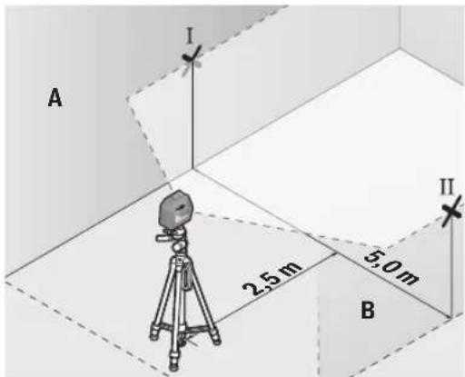
- Označite na 2,5 m udaljenosti od mernog alata na oba zida sredinu laserske linije (tačka I na zidu A i tačka II na zidu B).
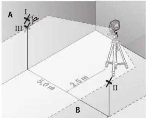
- Postavite merni alat za 180° okrenut na 5 m udaljenosti i iznivelišite ga.
- Merni alat usmerite uvis tako (pomoću stativa ili po potrebi podmetanjem) da sredina laserske linije tačno pogađa prethodno označenu tačku II na zidu B.
- Označite na zidu A sredinu laserske linije kao tačku III (vertikalno iznad odn. ispod tačke I).
- Razlika d između obe označene tačke I i III na zidu A predstavlja stvarno odstupanje mernog alata od horizontale.
Na mernoj deonici od 2 × 5 m = 10 m maksimalno dozvoljeno odstupanje iznosi:
10 m × ±0,3 mm/m = ±3 mm. Razlika d između tačaka I i III prema tome sme da iznosi maksimalno 3 mm.
Kontrola tačnosti nivelisanja vertikalne linije
Za kontrolu potreban Vam je otvor od vrata, kod kojih (na čvrstoj zemlji) sa svake strane vrata ima najmanje 2,5 m prostora.
- Postavite merni alat na 2,5 m rastojanja od otvora vrata na čvrstu ravnu podlogu (ne na stativ). Uključite merni alat i izaberite vertikalni režim rada. Usmerite lasersku liniju na otvor vrata i iznivelišite merni alat.
- Označite sredinu vertikalne laserske linije na podu otvora za vrata (tačka I), na razdaljini od 5 m od druge strane otvora za vrata (tačka II) kao i na gornjoj ivici otvora za vrata (tačka III).
- Na oddaljenosti 2,5 m od merilne naprave na obeh stenah označite sredino laserske linije (točka I na steni A in točka II na steni B).
- Okrenite mjerni alat za 180° bez promjene visine. Usmjerite ga na zid A tako da okomita linija lasera prolazi
kroz već označenu točku I. Mjerni alat iznivelirajte i označite križnu točku linija lasera na zidu A (točka III).
- Razlika d obje označene točke I i III na zidu A daje stvarno visinsko odstupanje mjernog alata.
- Na udaljenosti 2,5 m od mjernog alata označite na oba zida sredinu linije lasera (točka I na zidu A i točka II na zidu B).
- Postavite mjerni alat okrenut za 180° na udaljenosti 5 m i iznivelirajte ga.
- Mjerni alat usmjerite po visini (pomoću stativa ili eventualno podlaganjem) tako da sredina linije lasera točno udara na prethodno označenu točku II na zidu B.
- Na zidu A označite sredinu linije lasera kao točku III (okomito iznad odn. ispod točke I).
- Razlika d obje označene točke I i III na zidu A daje stvarno odstupanje mjernog alata od horizontale.
- Označite sredinu okomite linije lasera na dnu otvora vrata (točka I), na udaljenosti 5 m na drugoj strani otvora vrata (točka II) kao i na gornjem rubu otvora vrata (točka III).
- Okrenite mjerni alat za 180°. Pozicionirajte ga tako da sredina donje točke lasera pada na već označenu točku II. Iznivelirajte mjerni alat. Označite sredinu gornje točke lasera (točka III).
- Razlika d obje označene točke I i III na stropu daje stvarno odstupanje mjernog alata od okomice.
- Vërsiet lâzera starus uz tuvâko sienu A un nogaidiet, lîdz beidzas mërinstrumenta pašizlîdzinăšanās process. lezimëjiet lâzera staru veidoto liniju krustošanās vietas viduspunktu uz sienas A (punkts I).
Palma Tower 10th Floor
Jalan RA Kartini II-S Kaveling 6
Pondok Pinang, Kebayoran Lama
natural_image
Pure geometric lines forming a cross with a central circle (no text or symbols)العامودي على أرض-
-Ametha shgll (anpralpsu)
Sahba Technology Group
شارع مطار المثنى
بقداد
: ماتف بغداد: 964 (0) 7 901 930
Robert Bosch Morocco SARL
53.شارع الملازم محمد محرود
20300 الدار البيضاء
Copyright © 2016-2019 STMicroelectronics
All rights reserved.
Redistribution and use in source and binary forms, with or without modification, are permitted provided that the following conditions are met:
- Redistributions of source code must retain the above copyright notice, this list of conditions and the following disclaimer.
- Redistributions in binary form must reproduce the above copyright notice, this list of conditions and the following disclaimer in the documentation and/or other materials provided with the distribution.
- Neither the name of STMicroelectronics nor the names of its contributors may be used to endorse or promote products derived from this software without specific prior written permission.
THIS SOFTWARE IS PROVIDED BY THE COPYRIGHT HOLDERS AND CONTRIBUTORS "AS IS" AND ANY EXPRESS OR IMPLIED WARRANTIES, INCLUDING, BUT NOT LIMITED TO, THE IMPLIED WARRANTIES OF MERCHANTABILITY AND FITNESS FOR A PARTICULAR PURPOSE ARE DISCLAIMED. IN NO EVENT SHALL THE COPYRIGHT OWNER OR CONTRIBUTORS BE LIABLE FOR ANY DIRECT, INDIRECT, INCIDENTAL, SPECIAL, EXEMPLARY, OR CONSEQUENTIAL DAMAGES (INCLUDING, BUT NOT LIMITED TO, PROCUREMENT OF SUBSTITUTE GOODS OR SERVICES; LOSS OF USE, DATA, OR PROFITS; OR BUSINESS INTERRUPTION) HOWEVER CAUSED AND ON ANY THEORY OF LIABILITY, WHETHER IN CONTRACT, STRICT LIABILITY, OR TORT (INCLUDING NEGLIGENCE OR OTHERWISE) ARISING IN ANY WAY OUT OF THE USE OF THIS SOFTWARE, EVEN IF ADVISED OF THE POSSIBILITY OF SUCH DAMAGE.
- GCL 2-50 G Professional
- Deutsch
- Sicherheitshinweise
- Product Description and Specifications
- Intended Use
- Product Features
- Assembly
- Inserting/Changing the batteries
- Operation
- Starting Operation
- Switching On/Off
- Automatic shut-off
- Operating Modes
- Automatic Levelling
- Working with automatic levelling (see figures A-D)
- Working with the Incline Function (see figure E)
- Accuracy Check of the Measuring Tool
- Influences on Accuracy
- | English
- Checking the Height Accuracy of the Horizontal Line
- Checking the Level Accuracy of the Horizontal Line
- Checking the Level Accuracy of the Vertical Line
- | English
- Checking Plumb Accuracy
- Working Advice
- Working with the RM 10 Rotating Mount (see figures F-H)
- Working with the Laser Target Plate
- Working with the Tripod (Accessory)
- Securing with the universal holder (accessory) (see figure N)
- Working with the Holder LB 10 (accessory)
- Working with the Laser Receiver (accessory) (see figure N)
- Laser Goggles (Accessory)
- Example applications (see figures I–N)
- Maintenance and Service
- Maintenance and Cleaning
- After-Sales Service and Application Service
- Cambodia
- People's Republic of China
- China Mainland
- HK and Macau Special Administrative Regions
- India
- Indonesia
- | English
- Philippines
- Singapore
- Thailand
- Vietnam
- Bahrain
- Egypt
- Iran
- Iraq
- Jordan
- Kuwait
- Lebanon
- Libya
- Oman
- Qatar
- Saudi Arabia
- Syria
- United Arab Emirates
- Yemen
- Ethiopia
- Ghana
- Kenya
- Nigeria
- Tanzania
- Australia, New Zealand and Pacific Islands
- Myanmar
- Great Britain
- Ireland
- Republic of South Africa
- Customer service
- Gauteng - BSC Service Centre
- KZN - BSC Service Centre
- Western Cape - BSC Service Centre
- Bosch Headquarters
- | Français
- Armenia, Azerbaijan, Georgia
- Kyrgyzstan, Mongolia, Tajikistan, Turkmenistan, Uzbekistan
- Disposal
- Only for EU countries:
- Français
- Tunisie
- Bortskaffelse
- Avfallshantering
- | Slovenčina
- Бракуване
- | Srpski
- Provera preciznosti nivelacije horizontalne linije
- Kontrola tačnosti nivelisanja vertikalne linije
- -Ametha shgll (anpralpsu)
- Copyright © 2016-2019 STMicroelectronics
Brand : BOSCH
Model : GCL 2-50 G Professional
Category : Laser pointer