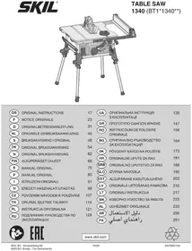
1340 AA - Saw SKIL - Free user manual and instructions
Find the device manual for free 1340 AA SKIL in PDF.



User questions about 1340 AA SKIL
0 question about this device. Answer the ones you know or ask your own.
Ask a new question about this device
Download the instructions for your Saw in PDF format for free! Find your manual 1340 AA - SKIL and take your electronic device back in hand. On this page are published all the documents necessary for the use of your device. 1340 AA by SKIL.
USER MANUAL 1340 AA SKIL
natural_image
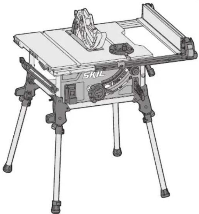
Technical line drawing of a tripod-mounted walk-in machine (no text or symbols visible)GB ORIGINAL INSTRUCTIONS 17
F NOTICE ORIGINALE 23
D ORIGINALBETRIEBSANLEITUNG 31
NL ORIGINELE GEBRUIKSAANWIJZING 40
S BRUKSANVISNING I ORIGINAL 48
DK ORIGINAL BRUGSANVISNING 54
N ORIGINAL BRUKSANVISNING 62
FIN ALKUPERÄISET OHJEET 68
E MANUAL ORIGINAL 75
(P) MANUAL ORIGINAL 83
I ISTRUZIONI ORIGINALI 91
H EREDETI HASZNÁLATI UTASÍTÁS 99
CZ PÜVODNÍM NÁVODEM K POUŽÍVÁNÍ 107
TR ORIJINAL İŞLETME TALİMATI 114
PL INSTRUKCJA ORYGINALNA 121
RU ПОДЛИННИК РУКОВОДСТВА ПО 129
ЭКСПЛУАТАЦИИ
UA ОРИГИНАЛЬНА ІНСТРУКЦІЯ 139
З ЕКСПЛУАТАЦІЇ
GR ΠΡΩΤΟΥΠΟ ΟΔΗΓΙΩΝ ΧΡΗΣΗΣ 147
RO INSTRUCTIUNI DE FOLOSIRE 156
ORIGINALE
BG ОРИГИНАЛНО РЪКОВОДСТВО 164
ЗА ЕКСПЛОАТАЦИЯ
SK PÔVODNÝ NÁVOD NA POUŽITIE 173
HR ORIGINALNE UPUTE ZA RAD 181
SRB ORIGINALNO UPUTSTVO ZA RAD 188
SLO IZVIRNA NAVODILA 195
EST ALGUPÄRANE KASUTUSJUHEND 203
LV ORIGINĀLĀ LIETOŠANAS PAMĀCĪBA 210
LT ORIGINALI INSTRUKCIJA 217
МК ИЗВОРНО УПАТСТВО ЗА РАБОТА 225
AL UDHËZIMET ORIGJINALE 233
AR دليل الاستعمال 256
④ RAHENMAI AUSLI 251
EAC
www.skil.com

| GB | EU Declaration of conformity | We declare under our sole responsibility that the stated products comply with all applicable provisions of the directives and regulations listed below and are in conformity with the following standards.Technical file at.* |
| Table saw Article number | ||
| F | Déclaration de conformité UE | Nous déclarons sous notre propre responsabilité que les produits décrits sont en conformité avec les directives, règlements normatifs et normes énumérés ci-dessous.Dossier technique auprès de:* |
| Table de sciage Numéro d'article | ||
| D | EU-Konformitätserklärung | Wir erklären in alleiniger Verantwortung, dass die genannten Produkte allen einschlägigen Bestimmungen der nachfolgend aufgeführten Richtlinien und Verordnungen entsprechen und mit folgenden Normen übereinstimmen.Technische Unterlagen bei:* |
| Tischsäge Sachnummer | ||
| NL | EU-conformiteitsverklaring | Wij verklaren op eigen verantwoordelijkheid dat de genoemde producten voldoen aan alle desbetreffende bepalingen van de hierna genoemde richtlijnen en verordningen en overeenstemmen met de volgende normen.Technisch dossier bij:* |
| Tafelzaag Productnummer | ||
| S | EU-konformitetsförklaring | Vi förklarar under eget ansvar att de nämnda produkterna uppfyller kraven i alla gällande bestämmelser i de nedan angivna direktiven och förordningarnas och att de stämmer överens med följande normer.Teknisk dokumentation.* |
| Bordssåg Produktnummer | ||
| DK | EU-overensstemmelseserklæring | Vi erklærer som eneansvarlige, at det beskrevne produkt er i overensstemmelse med alle gældende bestemmelser i følgende direktiver og forordninger og opfylder følgende standarder.Tekniske bilag ved:* |
| Bordsav Typenummer | ||
| N | EU-samsvarserklæring | Vi erklærer under eneansvar at de nevnte produktene er i overensstemmelse med alle relevante bestemmelser i direktivene og forordningene nedenfor og med følgende standarder.Teknisk dokumentasjon hos* |
| Bordsag Produktnummer | ||
| FIN | EU-vaatimustenmukaisuusvakuutus | Vakuutamme täten, että mainitut tuotteet vastaavat kaikkia seuraavien direktiivien ja asetusten asiaankuuluvia vaatimuksia ja ovat seuraavien standardien vaatimusten mukaisia.Tekniset asiakirjat saatavana.* |
| Käsisaha Tuotenumero | ||
| E | Declaración de conformidad UE | Declaramos bajo nuestra exclusiva responsabilidad, que los productos nombrados cumplen con todas las disposiciones correspondientes de las directivas y los reglamentos mencionados a continuación y están en conformidad con las siguientes normas.Documentos técnicos de:* |
| Sierra de mesa Número de artículo | ||
| P | Declaração de conformidade CE | Declaramos sob nossa exclusiva responsabilidade que os produtos mencionados cumprem todas as disposições e os regulamentos indicados e estão em conformidade com as seguintes normas.Documentação técnica pertencente à:* |
| Serra de mesa Número do produto | ||
| I | Dichiarazione di conformità UE | Dichiariamo sotto la nostra piena responsabilità che i prodotti indicati sono conformi a tutte le disposizioni pertinenti delle direttive e dei regolamenti elencati di seguito, nonché alle seguenti normative.Documentazione tecnica presso:* |
| Troncatrice da banco Codice prodotto | ||
| H | EU konformitási nyilatkozat | Egyedüli felelőséggel kijelentjük, hogy a megnevezett termékek megfelelnek az alábbiakban felsorolásra kerülő irányelvek és rendeletek valamennyi idevágó előírásainak és megfelelnek a következő szabványoknak.Műszaki dokumentumok megőrzési pontja:* |
| Asztali fűrész Cikkszám | ||
| CZ | EU prohlášení o shodě | Prohlašujeme na výhradní zodpovědnost, že uvedený výrobek splňuje všechna příslušná ustanovení niže uvedených smérnic a nařizení a je v souladu s následujícimi normami.Technické podklady u:* |
| Stolní pila Objednaci číslo | ||
| TR | AB Uygunluk beyani | Tek sorumlu olarak, tanimlanan ürünün aşağıdaki yönetmelik ve direktiflerin geçerli bütün hükümlerine ve aşağıdaki standartlara uygun olduğunu beyan ederiz.Teknik belgelerin bulunduğu yer:* |
| Tezgah tipi daire testere Ürün kodu | ||
| PL | Deklaracja zgodności UE | Oświadczamy z pełną odpowiedzialnością, że niniejsze produkty odpowiadają wszystkim wymaganiom poniżej wyszczególnionych dyrektyw i rozporządzeń, oraz że są zgodne z następującymi normami.Dokumentacja techniczna:* |
| Piła stołowa Numer katalogowy | ||
| RU | Заявление о соответствии ЕС | Мы заявляем под нашу единоличную ответственность, что названные продукты соответствуют всем действующим предписаниям нижеуказанных директив и распоряжений, а также нижеуказанных норм.Техническая документация хранится у:* |
| Настольная циркулярная пила Товарный номер | ||
| UA | Заява про відповідність ЄС | Мизаявляемо під нашу одноособову відповідальність, що названі вироби відповідають усім чинним положеням нищеозначених директив і розпоряджень, а також нижчеозначеним нормам.Технічна документация зберігається у:* |
| Настільна пила Товарный номер |
| GR | Δήλωση πιστότητας EEΕπιτραπέζιο δισκοπρίουν | Αριθμός ευρετηρίου | Δηλώνουμε με αποκλειστική μας ευθύνη, ότι τα αναφερόμενα προϊόντα αντιστοιχούν σε όλες τις σχετικές διατάξεις των πιο κάτω αναφερόμενων οδηγιών και κανονισμών και ταυτίζονται με τα ακόλουθα πρότυπα.Τεχνικά έγγραφα στη:* |
| RO | Declarație de conformitate UEFerăstrău de masă | Număr de identificare | Declarăm pe proprie răspundere că produsele menționate corespund tuturor dispozițiilor relevante ale directivelor și reglementărilor enumerate în cele ce urmează și sunt în conformitate cu următoarele standarde.Documentație tehnică la:* |
| BG | EC декларация за съответствиеНастолен циркуляр | Каталожен номер | С пълна отговорност ние декларираме, че посочените продукти отговарят на всички валидни изисквания на директивите и разпоредбите по-долу и съответства на следните стандарти.Техническа документация при:* |
| SK | Pôvodnej EU vyhlásenie o zhodeStolová píla Vecné číslo | Vyhlasujeme na výhradnú zodpovednosť, že uvedený výrobok spíňa všetky prislušné ustanovenia nižšie uvedených smernic a nariadení a je v súlade s nasledujúcimi normami.Technické podklady má spoločnosť:* | |
| HR | EU izjava o sukladnostiStolna pila Kataloški broj | Pod punom odgovornošću izjavljujemo da navedeni proizvodi odgovaraju svim relevantnim odredbama direktiva i propisima navedenima u nastavku i da su sukladni sa sljedećim normama.Tehnička dokumentacija se može dobiti kod:* | |
| SRB | EU-izjava o usaglašenostiStona testera Broj predmeta | Na sopstvenu odgovornost izjavljujemo, da navedeni proizvodi odgovaraju svim dotičnim odredbama naknadno navedenih smernica u uredaba i dá su u skladu sa sledećim standardima.Tehnička dokumentacija kod:* | |
| SLO | Izjava o skladnosti ESKrožna žaga Številka artikla | Izjavljamo pod izključno odgovornostjo, da je omenjen izdelek v skladu z vsemi relevantnimi določili direktiv in uredb ter ustreza naslednjim standardom.Tehnična dokumentacija pri:* | |
| EST | EL-vastavusdeklaratsioonSaepink Tootenumber | Kinnitame ainuvastutajatena, et nimetatud tooted vastavad järgnevalt loetletud direktiivide ja määruste köikidele asjaomastele nõuetele ja on kooskõlas järgmiste normidega.Tehnilised dokumentid saadaval:* | |
| LV | Deklarăcija par atbilstību EK standartiemGalda zāgis | Izstrādājuma numurs | Mēs ar pilnu atbildību pazinojam, ka šeit aplūkotie izstrādājumi atbilst visiem tālāk minētajās direktīvās un rīkojumos ietvertajām saistošajām nostādnēm, kā arī sekojošiem standartiem.Tehniskā dokumentacija no:* |
| LT | ES atitikties deklaracijaStalinis pjūklas Gaminio numeris | Atsakingai pareiškiame, kad išvardyti gaminiai atitinka visus privalomus žemiau nurodytu direktyvy ir reglamentu reikalavimus ir šiuos standartus.Techninė dokumentacija saugoma:* | |
| MK | EU-Изјава за сообразностПила за на маса Број на артикл | Со целосна одговорност изјавуваме, дека опишаните производи се во согласност со сите релевантни одредби на следните регулативи и прописи и се во согласност со следните норми.Техничка документација кaj:* | |
| AL | EU Deklarata e konformitetitBango Numri i nenit | Ne deklarojmě me përgjegjësině toně të vetme se produktet e paraçitura janě në përputhje me të gjitha dispozitat e zbatueshme të direktivave dhe rregulloreve të listuara mě poshtě dhe janě në përputhje me standardet si mě poshtě.Dosja teknike në:* | |
| 1340 BT1*1340** 2006/42/EC | EN 62841-1:2015EN 62841-4-1:2014 + A11:2017 | ||
| 2014/30/EU EN 55014-1:2017EN 55014-2:2015EN 61000-3-2:2014EN 61000-3-3:2013 + A1:2019 | |||
| 2011/65/EU EN 50581:2012 |
| GB | 2006/42/EC: EC type examination no. 4820026.20001 by notified body no. 0158. DEKRA Testing and Certification GmbH, Handwerkstraße 15,70565, Stuttgart, GermanyTechnical file at.* |
| F | 2006/42/CE: Examen CE de type n° 4820026.20001 effectué par l'office de contrôle notifié n° 0158. DEKRA Testing and Certification GmbH,Handwerkstraße 15, 70565, Stuttgart, GermanyDossier technique auprès de:* |
| D | 2006/42/EG: EG-Baumusterprüfung Nr. 4820026.20001 durch notifizierte Prüfstelle Nr. 0158. DEKRA Testing and Certification GmbH,Handwerkstraße 15, 70565, Stuttgart, GermanyTechnische Unterlagen bei:* |
| NL | 2006/42/EG: EG-typekeuring nr. 4820026.20001 door aangemelde instantie nr. 0158. DEKRA Testing and Certification GmbH, Handwerkstraße15, 70565, Stuttgart, GermanyTechnisch dossier bij:* |
| S | 2006/42/EG: EG-prototypeprovning nr. 4820026.20001 utfört av notifierat provningsställe nr. 0158. DEKRA Testing and Certification GmbH,Handwerkstraße 15, 70565, Stuttgart, GermanyTeknisk dokumentation:* |
| DK | 2006/42/EF: EF-typogodkendelses-nr. 4820026.20001 via bemyndiget organ nr. 0158. DEKRA Testing and Certification GmbH, Handwerkstraße15, 70565, Stuttgart, GermanyTekniske bilag ved:* |
| N | 2006/42/EF: EU-typogodkjenningsnr. 4820026.20001 fra bemyndiget organ nr. 0158. DEKRA Testing and Certification GmbH, Handwerkstraße15, 70565, Stuttgart, GermanyTeknik dokumentasjon hos:* |
| FIN | 2006/42/EY: EY-typpitarkastuksen nro 4820026.20001, jonka on suorittanut valtuutettu tarkastuslaitos nro 0158. DEKRA Testing and CertificationGmbH, Handwerkstraße 15, 70565, Stuttgart, GermanyTekniset asiakirjat saatavana:* |
| E | 2006/42/CE: Comprobación de ejecuciones CE N° 4820026.20001 por centro de comprobación notificado N° 0158. DEKRA Testing andCertification GmbH, Handwerkstraße 15, 70565, Stuttgart, GermanyDocumentos técnicos de:* |
| P | 2006/42/CE: Certificado de exame CE de tipo n.° 4820026.20001 através do organismo de inspeção notificado n.° 0158. DEKRA Testing andCertification GmbH, Handwerkstraße 15, 70565, Stuttgart, GermanyDocumentação técnica pertencente a:* |
| I | 2006/42/CE: Verifica CE N. 4820026.20001 a cura dell'ente incaricato N. 0158. DEKRA Testing and Certification GmbH, Handwerkstraße 15,70565, Stuttgart, GermanyDocumentazione tecnica presso:* |
| H | 2006/42/EK: 4820026.20001 sz. EK-mintavizsgálat, végrehajtotta a 0158 sz. notifikált testület (címe DEKRA Testing and Certification GmbH,Handwerkstraße 15, 70565, Stuttgart, Germany)Muszaki dokumentumok megórzési pontja:* |
| CZ | 2006/42/ES: ES přezkoušení typu č. 4820026.20001 zaregistrovanou zkušebnou č. 0158. DEKRA Testing and Certification GmbH,Handwerkstraße 15, 70565, Stuttgart, GermanyTechnicke podklady u:* |
| TR | 2006/42/AT: AT numune No. 4820026.20001 Test kuruluşu No. 0158. DEKRA Testing and Certification GmbH, Handwerkstraße 15, 70565,Stuttgart, GermanyTeknik belgelerin bulunduğu yer:* |
| PL | 2006/42/WE: Badanie homologacyjne typu WE, nr 4820026.20001 przeprowadzone przez Notyfikowaną Jednostkę Kontrolującą Nr 0158. DEKRA Testing and Certification GmbH, Handwerkstraße 15, 70565, Stuttgart, GermanDokumentacja techniczna:* |
| RU | 2006/42/EC: Испытание конструктивного образца в соответствии с предписаниями EC No 4820026.20001 было произведенозарегистрированным испытательным центром No 0158. DEKRA Testing and Certification GmbH, Handwerkstraße 15, 70565, Stuttgart, GermanyТехническая документация хранится y:* |
| UA | 2006/42/EC: Перевірка прототипу відповідно до приписів ЄС С № 4820026.20001 авторизованим іспитовим центром No 0158. DEKRATesting and Certification GmbH, Handwerkstraße 15, 70565, Stuttgart, GermanyТехнічна документация зберігається y:* |
| GR | 2006/42/EK: ЕЛёухос катаσκευαστικού протупою ЕК аріг. 4820026.20001 μέσω αναγνωρισμένου ινστιτούτου ελέγχου αριθ. 0158. DEKRATesting and Certification GmbH, Handwerkstraße 15, 70565, Stuttgart, GermanyТехуика ёγγραφα στη:* |
| RO | 2006/42/CE: Examinare CE de tip nr. 4820026.20001 de către organism notificat nr. 0158. DEKRA Testing and Certification GmbH,Handwerkstraße 15, 70565, Stuttgart, GermanyDocumentatie tehnică la:* |
| BG | 2006/42/EO: EO-сертификат за изпитване на образец No 4820026.20001 от оторизиран сертифициращ орган No 0158. DEKRA Testing andCertification GmbH, Handwerkstraße 15, 70565, Stuttgart, GermanyТехническа документация при:* |
| SK | 2006/42/ES: ES preskúšanie typu č. 4820026.20001 zaregistrovanou skúšobňou č. 0158. DEKRA Testing and Certification GmbH,Handwerkstraße 15, 70565, Stuttgart, GermanyTechnické podklady má spoločnost:* |
| HR | 2006/42/EZ: Pregled tipą 4820026.20001 Prijavljeno tijelo 0158. DEKRA Testing and Certification GmbH, Handwerkstraße 15, 70565, Stuttgart, GermanyTehnička dokumentacija se može dobiti kod:* |
| SRB | 2006/42/EG: EU-ispitivanje prototipova br. 4820026.20001 putem registrovanog zavoda za ispitivanje br. 0158. DEKRA Testing and CertificationGmbH, Handwerkstraße 15, 70565, Stuttgart, GermanyTehnička dokumentacija kod:* |
| SLO | 2006/42/ES: Tipski preizkus ES št. 4820026.20001 pri pristojnem organu št. 0158. DEKRA Testing and Certification GmbH, Handwerkstraße 15,70565, Stuttgart, GermanyTehnicna dokumentacija pri:* |
| EST | 2006/42/EU: EÜ-tübihindamine nr 4820026.20001 teavitatud asutuses nr 0158. DEKRA Testing and Certification GmbH, Handwerkstraße 15,70565, Stuttgart, GermanyTehnilised dokumendid saadaval:* |
| LV | 2006/42/EK: EK izstrădăjuma tipa părbaude Nr. 4820026.20001, kas veikta registrētă sertifikacijas iestādē Nr. 0158. DEKRA Testing andCertification GmbH, Handwerkstraße 15, 70565, Stuttgart, GermanyTehniska dokumentacija no:* |
| LT | 2006/42/EG: EG tipo tyrimo Nr. 4820026.20001, tikrino notifikuota patikros jstaiga Nr. 0158. DEKRA Testing and Certification GmbH,Handwerkstraße 15, 70565, Stuttgart, GermanyTechnine dokumentacija saugoma:* |
| MK | 2006/42/EG: EG-типско испитуванье бр. 4820026.20001 од страна на овластено тело бр. 0158. DEKRA Testing and Certification GmbH,Handwerkstraße 15, 70565, Stuttgart, GermanyТехничка документација кал:* |
AL 2006/42/EC: Ekzaminimi i KE-së për tipin me numër 4820026.20001, organizmi i njoftuar: 0158. DEKRA Testing and Certification GmbH, Handwerkstraße 15, 70565, Stuttgart, Germany Dosja teknike në:*

Skil BV
*Konijnenberg 62
4825 BD Breda
The Netherlands
Olaf Dijkgraaf
Approval Manager
Skil BV, Konijnenberg 62, 4825 BD Breda, NL
16.10.2020
1
1340

text_image
90 mm 90°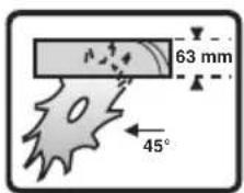
text_image
63 mm 45°②
natural_image
Silhouette of a person using a document inside a circle (no text or symbols)③

natural_image
Icon of a person wearing headphones inside a circle (no text or symbols)4
5
⑥ a
ADBCEHGJ
text_image
X W U AG T S R Q P V K L M N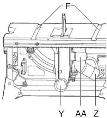
text_image
F Y AA Z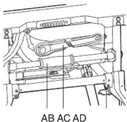
text_image
AB AC AD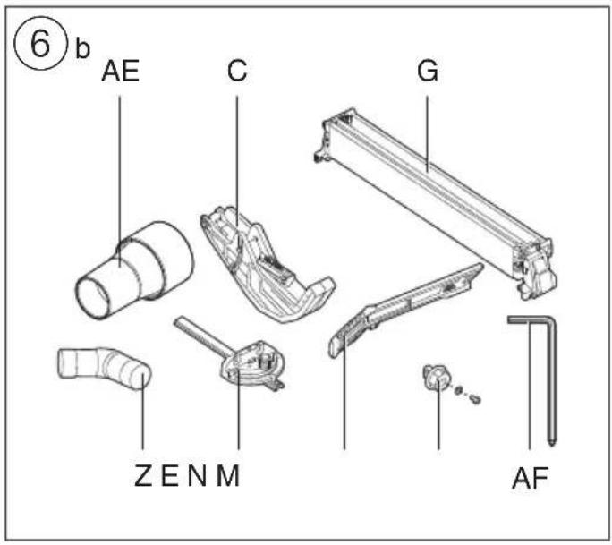
text_image
⑥ b AE C G ZENM AF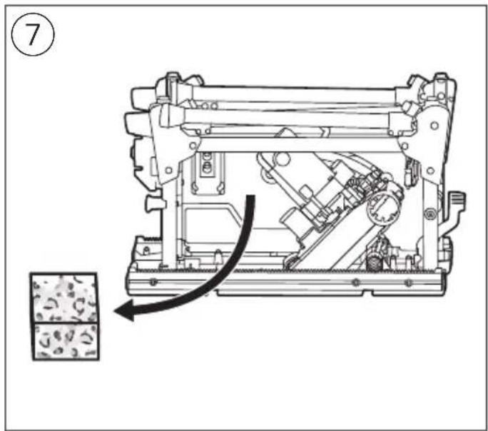
text_image
⑦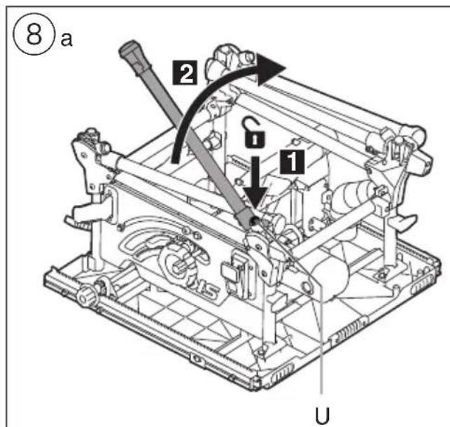
text_image
⑧ a 2 G 1 U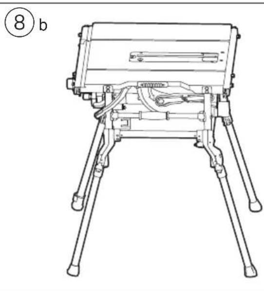
natural_image
Line drawing of a tripod-mounted device with legs and legs fixed, no text or symbols present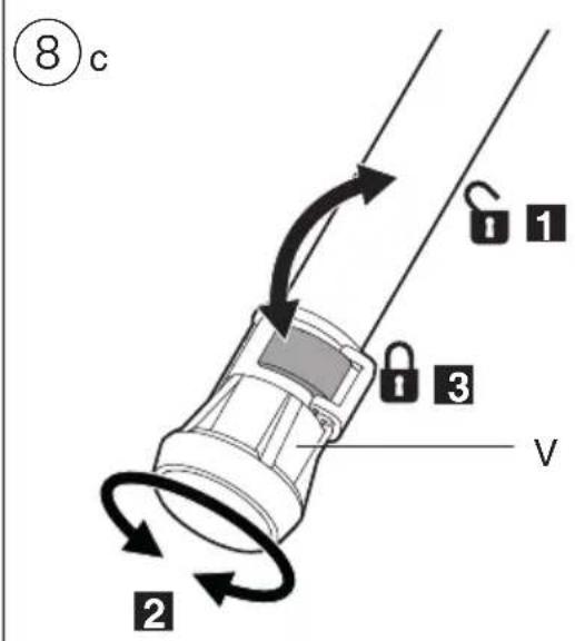
text_image
⑧c 1 2 3 v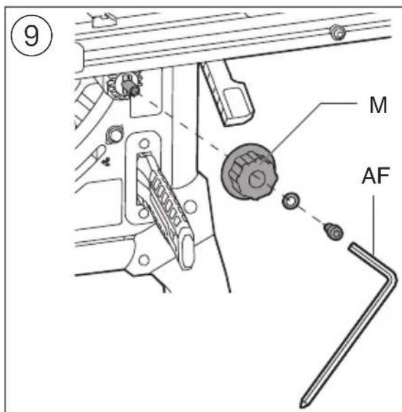
text_image
⑨ M AF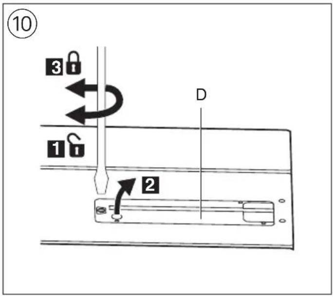
text_image
⑩ 3 1 D 2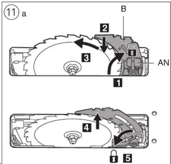
text_image
⑪ a B 2 3 AN 1 4 5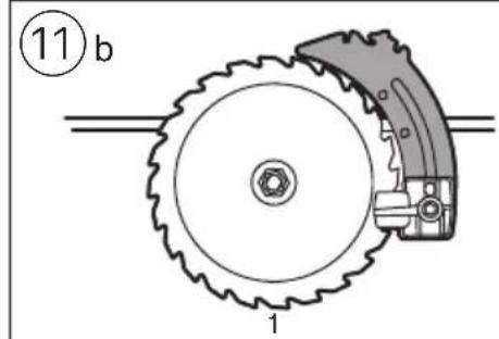
text_image
⑪ b 1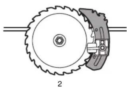
natural_image
Mechanical diagram showing a gear and cam mechanism (no text or symbols)
natural_image
Mechanical diagram showing a gear and cam mechanism (no text or symbols)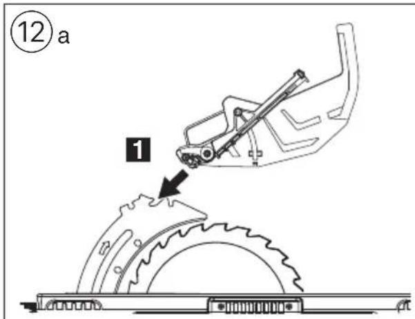
text_image
⑫ a 1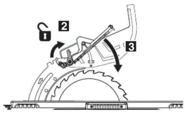
text_image
Technical diagram of a mechanical device with labeled parts and directional arrows indicating motion or assembly.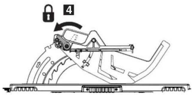
text_image
4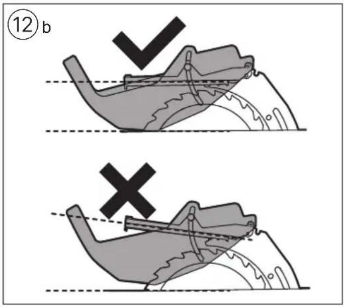
text_image
⑫b X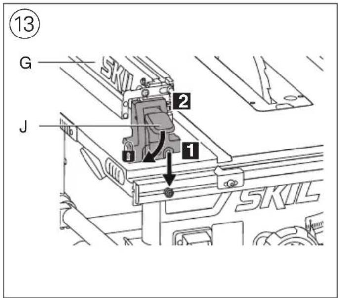
text_image
13 G 2 J 1 SKIL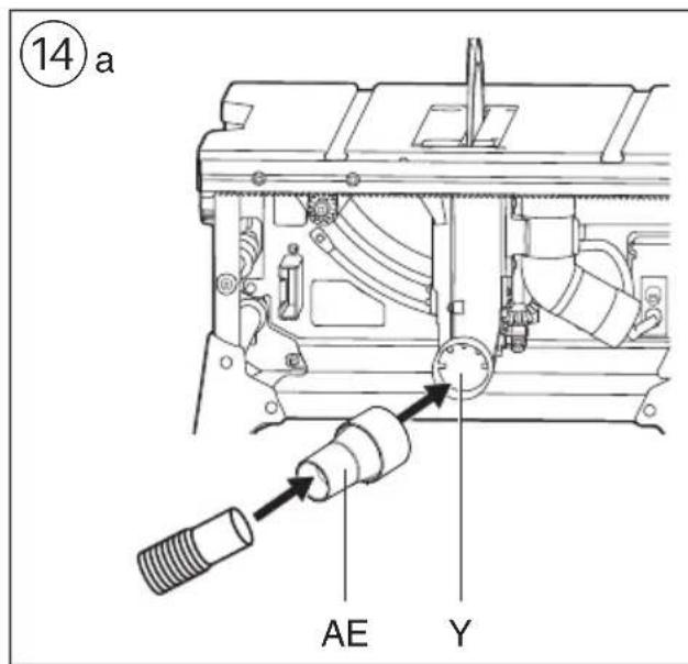
text_image
⑭ a AE Y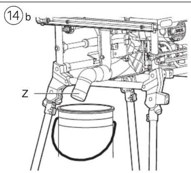
text_image
(14) b Z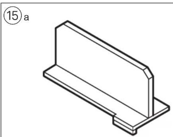
natural_image
Isometric line drawing of a rectangular metal bracket with a flat top and base (no text or symbols)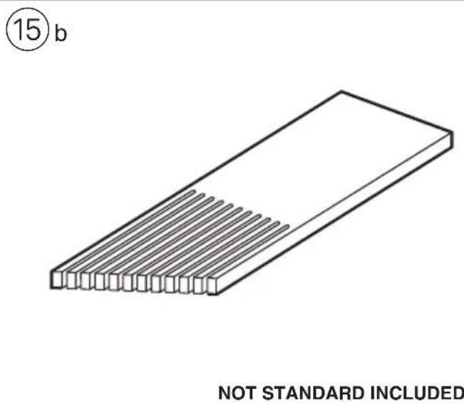
natural_image
Isometric line drawing of a rectangular object with parallel grooves, labeled with circled number 15 and 'NOT STANDARD INCLUDED' below (text not part of the diagram)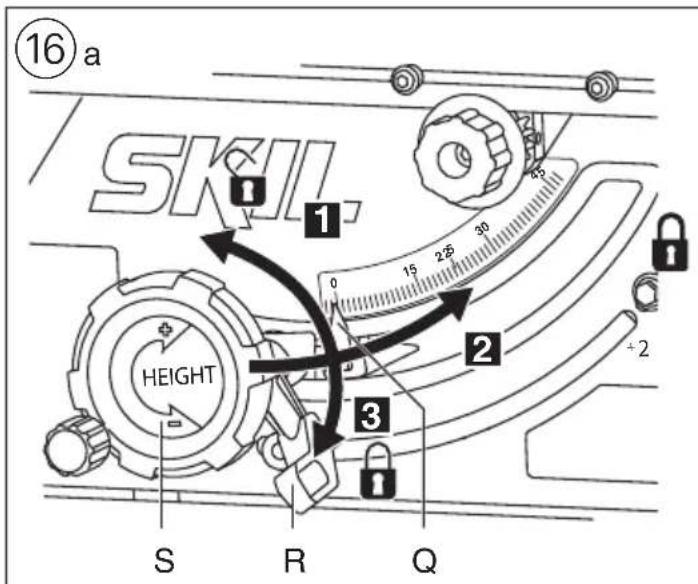
text_image
16a SKIL. 1 0 25 30 2 Height 2 3 S R Q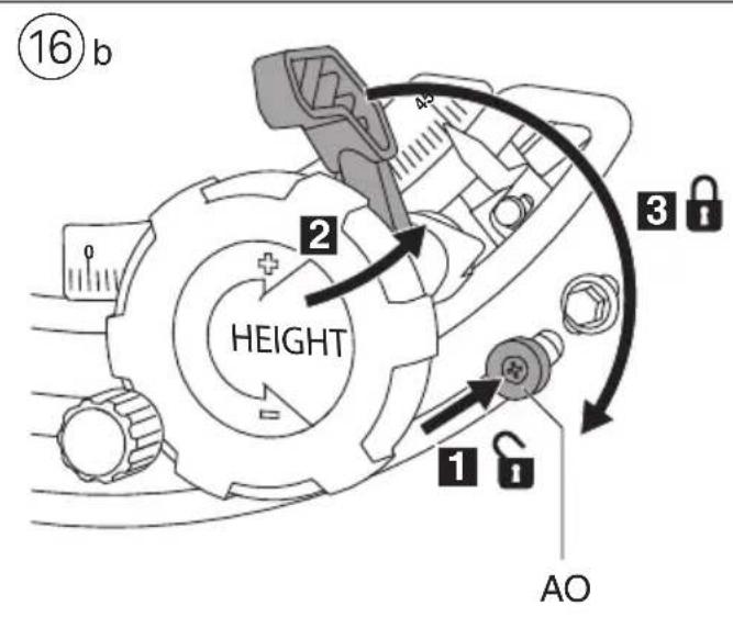
text_image
16 b 2 HEIGHT 3 1 AO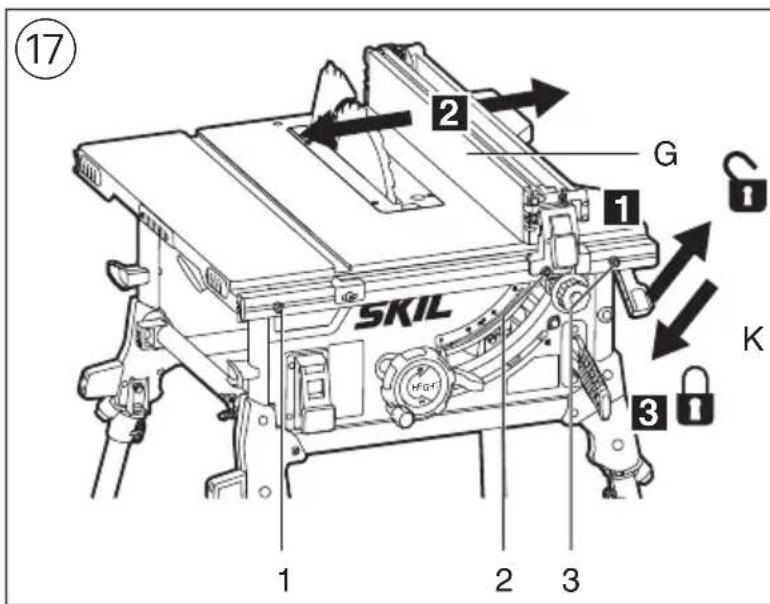
text_image
17 2 G 1 SKIL K 3 1 2 3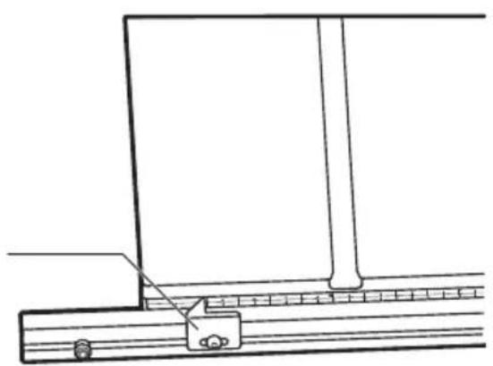
natural_image
Technical line drawing of a mechanical assembly with a bracket and rail (no text or symbols)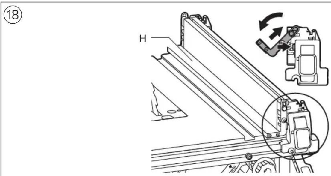
text_image
⑱ H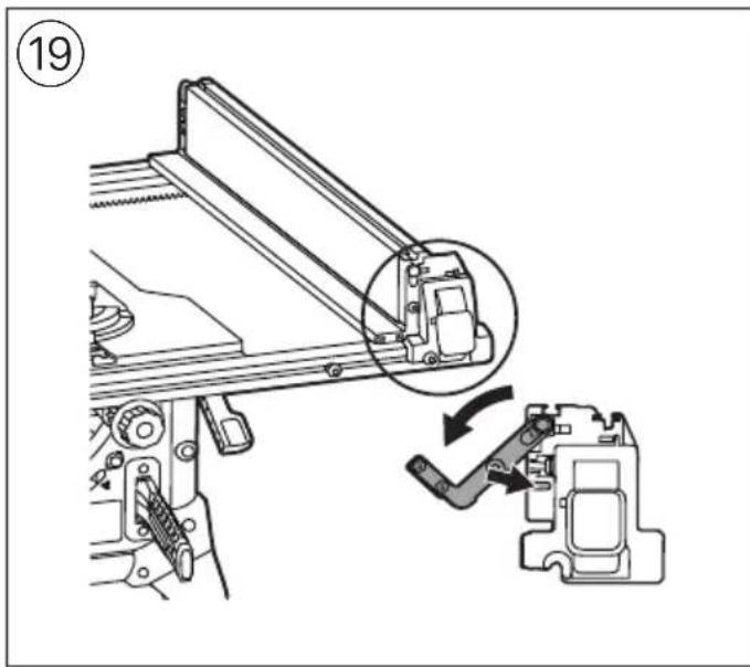
natural_image
Mechanical assembly diagram showing a lever mechanism and a close-up of a component (no text or symbols present)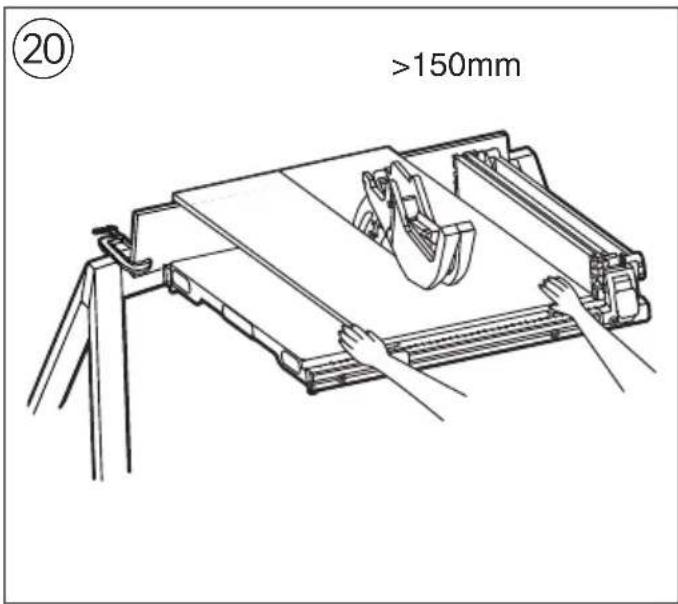
text_image
20 >150mm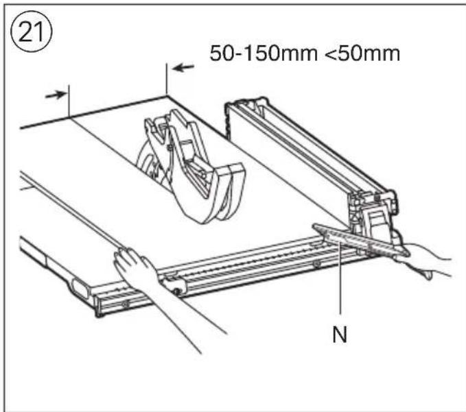
text_image
21 50-150mm <50mm N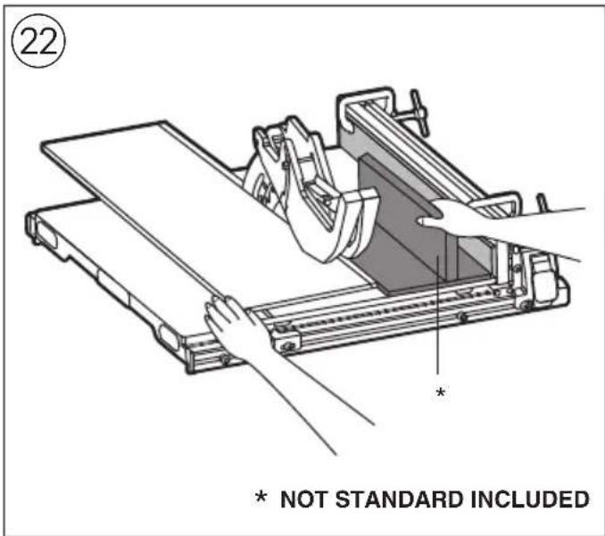
text_image
22 * NOT STANDARD INCLUDED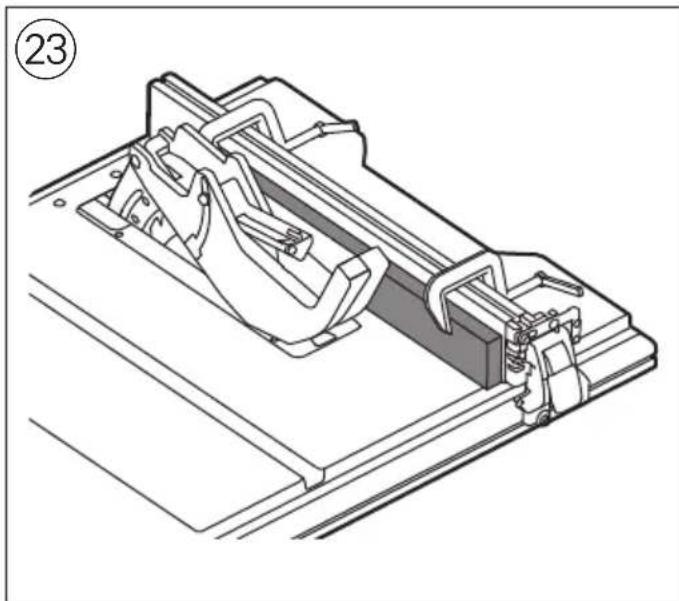
natural_image
Technical line drawing of a mechanical assembly with no visible text or symbols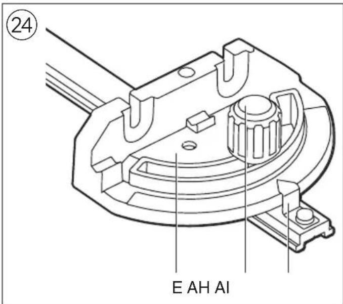
text_image
24 E AH AI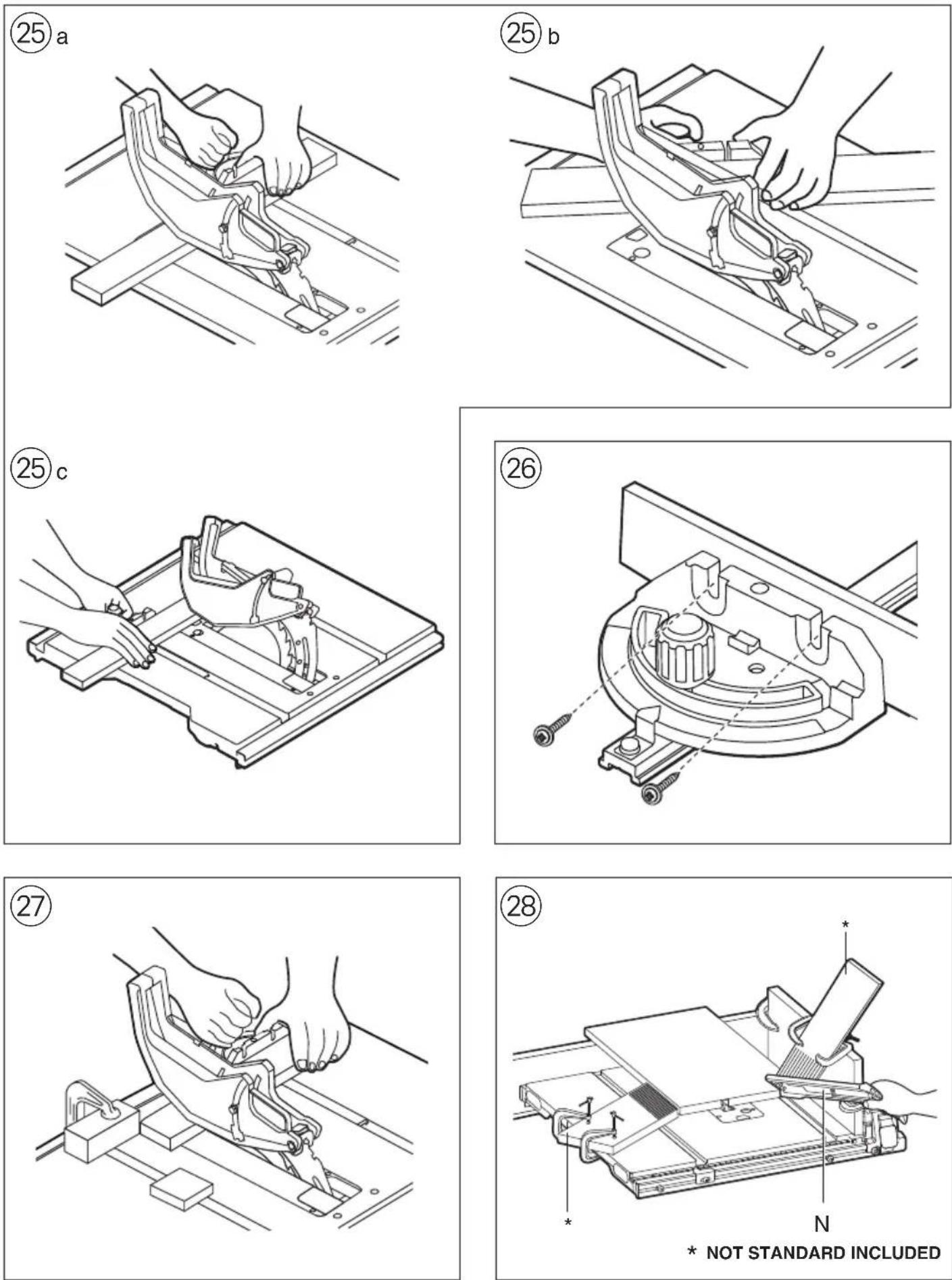
text_image
29 T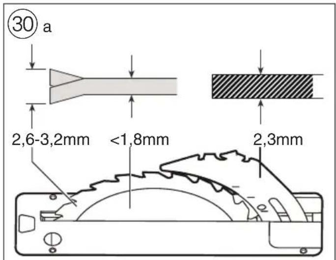
text_image
30 a 2,6-3,2mm <1,8mm 2,3mm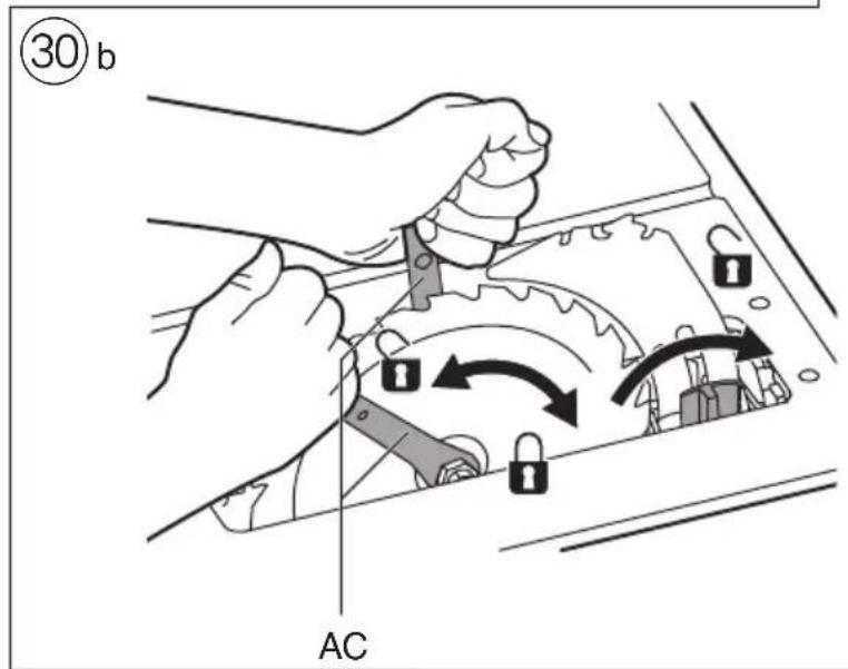
text_image
③0 b AC
text_image
AL AM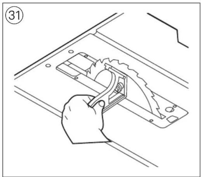
natural_image
Line drawing of a hand using a tool to cut or install a mechanical component, no text or symbols present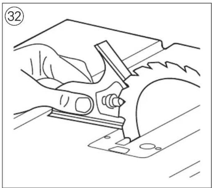
natural_image
Line drawing of a hand using a tool to cut or install a mechanical component, no text or symbols present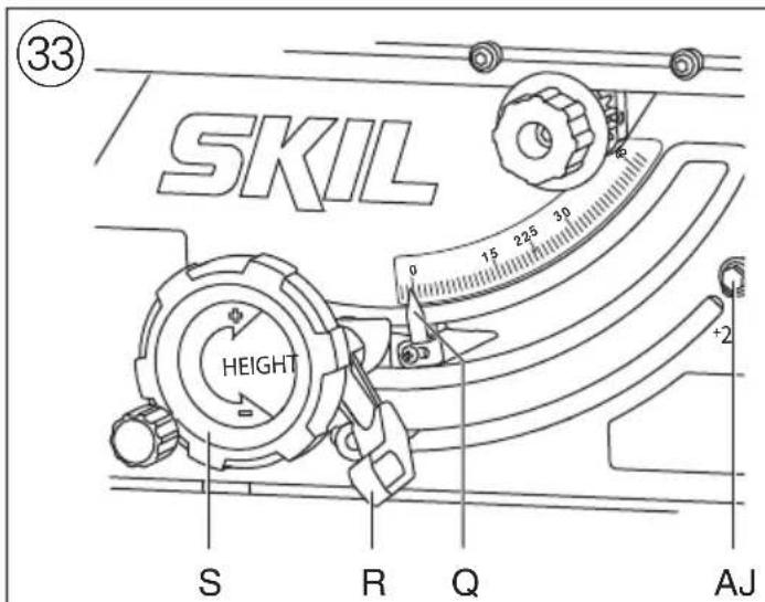
text_image
33 SKIL HEIGHT S R Q AJ
text_image
HEIGHT AK AO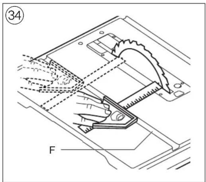
text_image
34 F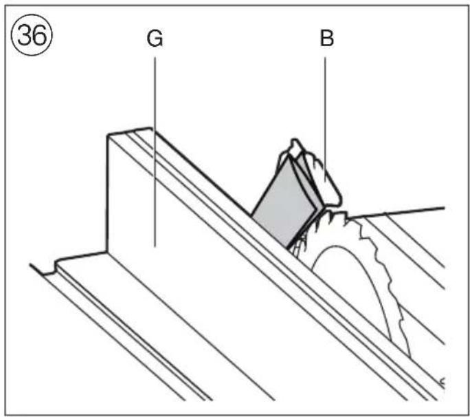
text_image
③6 G B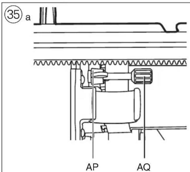
text_image
35 a AP AQ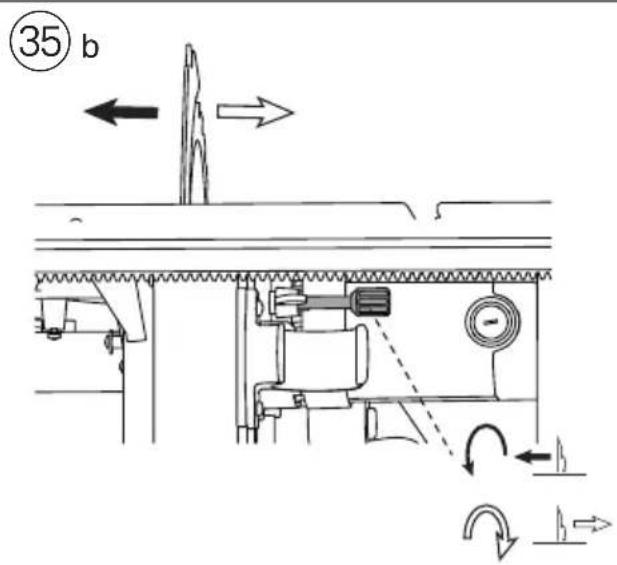
text_image
35 b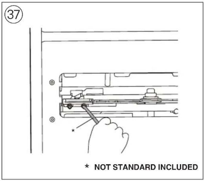
text_image
37 * NOT STANDARD INCLUDED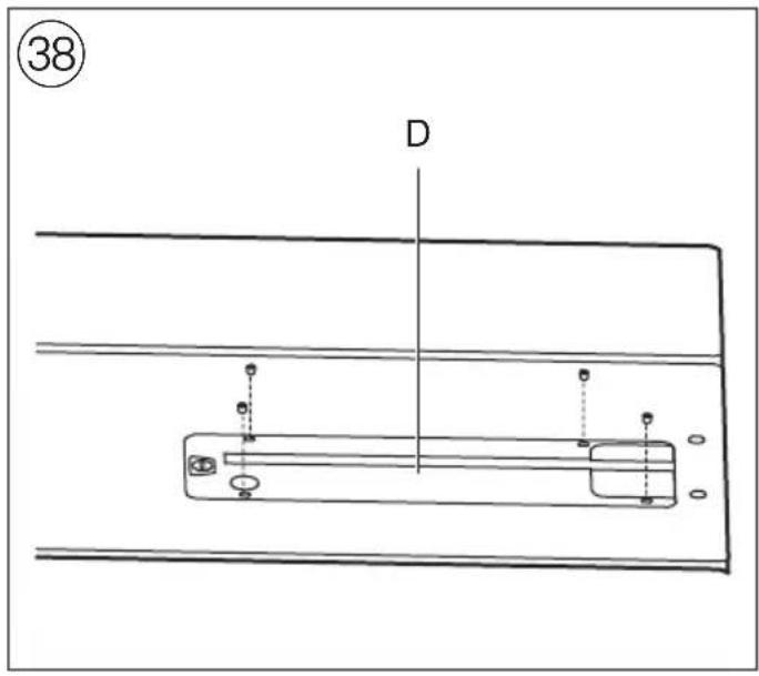
text_image
38 D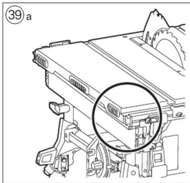
text_image
⑲ 39 a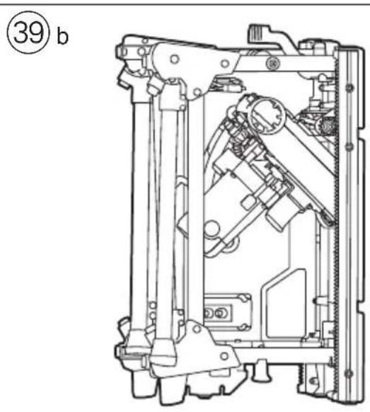
natural_image
Technical line drawing of a mechanical assembly with no visible text or symbols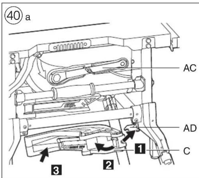
text_image
40 a AC AD C 1 2 3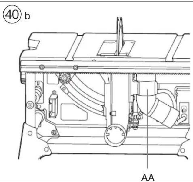
text_image
40 b AA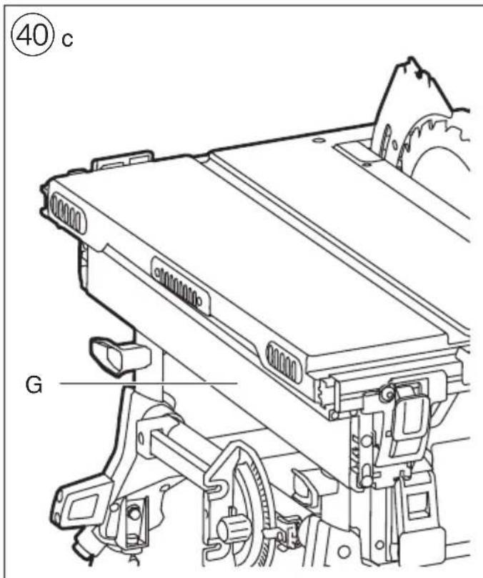
text_image
④0 c G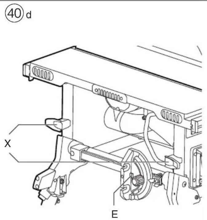
text_image
④0 d X E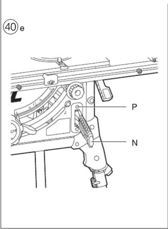
text_image
④0 e P N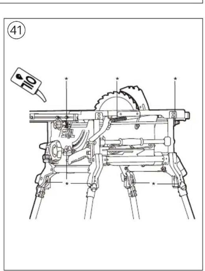
text_image
41 10 * * * ENL * *GB
Table saw 1340 INTRODUCTION
- This tool is intended as a stationary machine for lengthways and crossways cutting of wood with straight cuts as well as angle cuts (horizontal mitre angles of -60^ to +60^ as well as vertical bevel angles of -2^ to +47^ are possible)
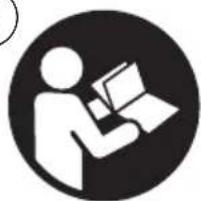
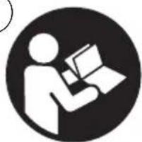
- Read and save this instruction manual ②
• This tool is not intended for professional use - Check whether the packaging contains all parts as illustrated in drawing ⑥b
- Only use the tool when correctly and completely assembled (be aware that Skil cannot be hold responsible for tool damage and/or personal injuries resulting from the incorrect assembly of the tool)
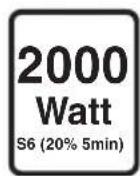
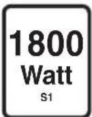
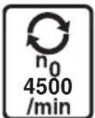
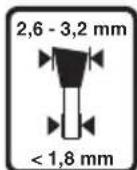
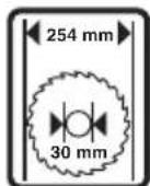
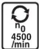
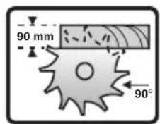
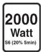
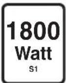
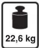
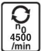
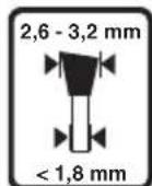
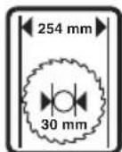
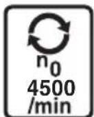
TECHNICAL DATA①
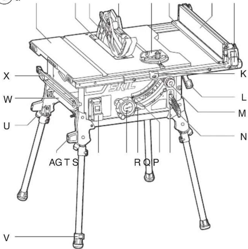
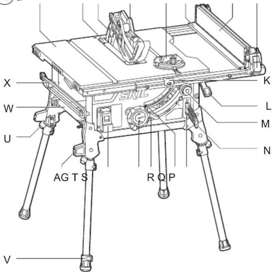
TOOL ELEMENTS ⑥
A Table top
B Riving knife
C Protective guard
D Table insert
E Mitre gauge
F Mitre gauge slot
G Rip fence
H Auxiliary fence / workpiece support
J Clamping lever
K Rip fence distance indicator
L Rail lock lever
M Rail drive knob
N Push stick
P Push stick storage
Q Bevel angle indicator
R Bevel locking lever
S Height adjustment wheel
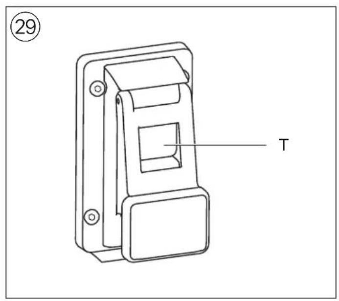
T On/off switch
U Knob for folding legs
V Adjustable foot
W Mitre guage storage
X Cable storage hook
Y Dust port
Z Dust deflector
AA Dust deflector storage
AB Transport handle
AC Wrenches
AD Protective guard storage
AE Vacuum cleaner adapter
AF Hex key
AG Support foot
AH Mitre angle lock knob
AI Mitre angle indicator
AJ Screw for adjusting bevel angle (right)
AK Screw for adjusting bevel angle (left)
AL Flange
AM Blade nut
AN Riving knife locking lever
AO Release knob (bevel angle)
AP Wing nut
AQ Adjustment bolt
SAFETY
GENERAL POWER TOOL SAFETY WARNINGS
A WARNING Read all safety warnings, instructions, illustrations and specifications provided with this power tool. Failure to follow all instructions listed below may result in electric shock, fire and/or serious injury.
Save all warnings and instructions for future reference.
The term "power tool" in the warnings refers to your mains-operated (corded) power tool or battery-operated (cordless) power tool.
1) WORK AREA SAFETY
a) Keep work area clean and well lit. Cluttered or dark areas invite accidents.
b) Do not operate power tools in explosive atmospheres, such as in the presence of flammable liquids, gases or dust. Power tools create sparks which may ignite the dust or fumes.
c) Keep children and bystanders away while operating a power tool. Distractions can cause you to lose control.
2) ELECTRICAL SAFETY
a) Power tool plugs must match the outlet. Never modify the plug in any way. Do not use any adapter plugs with earthed (grounded) power tools. Unmodified plugs and matching outlets will reduce risk of electric shock.
b) Avoid body contact with earthed or grounded surfaces such as pipes, radiators, ranges and refrigerators. There is an increased risk of electric shock if your body is earthed or grounded.
c) Do not expose power tools to rain or wet conditions. Water entering a power tool will increase the risk of electric shock.
d) Do not abuse the cord. Never use the cord for carrying, pulling or unplugging the power tool. Keep cord away from heat, oil, sharp edges or moving parts. Damaged or entangled cords increase the risk of electric shock.
e) When operating a power tool outdoors, use an extension cord suitable for outdoor use. Use of a cord suitable for outdoor use reduces the risk of electric shock.
f) If operating a power tool in a damp location is unavoidable, use a residual current device (RCD) protected supply. Use of an RCD reduces the risk of electric shock.
3) PERSONAL SAFETY
a) Stay alert, watch what you are doing and use common sense when operating a power tool. Do not use a power tool while you are tired or under the influence of drugs, alcohol or medication. A moment of inattention while operating power tools may result in serious personal injury.
b) Use personal protective equipment. Always wear eye protection. Protective equipment such as a dust mask, non-skid safety shoes, hard hat, or hearing protection used for appropriate conditions will reduce personal injuries.
c) Prevent unintentional starting. Ensure the switch is in the off-position before connecting to power source and/or battery pack, picking up or carrying
the tool. Carrying power tools with your finger on the switch or energising power tools that have the switch on invites accidents.
d) Remove any adjusting key or wrench before turning the power tool on. A wrench or a key left attached to a rotating part of the power tool may result in personal injury.
e) Do not overreach. Keep proper footing and balance at all times. This enables better control of the power tool in unexpected situations.
f) Dress properly. Do not wear loose clothing or jewellery. Keep your hair and clothing away from moving parts. Loose clothes, jewellery or long hair can be caught in moving parts.
g) If devices are provided for the connection of dust extraction and collection facilities, ensure these are connected and properly used. Use of dust collection can reduce dust-related hazards.
h) Do not let familiarity gained from frequent use of tools allow you to become complacent and ignore tool safety principles. A careless action can cause severe injury within a fraction of a second.
4) POWER TOOL USE AND CARE
a) Do not force the power tool. Use the correct power tool for your application. The correct power tool will do the job better and safer at the rate for which it was designed.
b) Do not use the power tool if the switch does not turn it on and off. Any power tool that cannot be controlled with the switch is dangerous and must be repaired.
c) Disconnect the plug from the power source and/or remove the battery pack, if detachable, from the power tool before making any adjustments, changing accessories, or storing power tools. Such preventive safety measures reduce the risk of starting the power tool accidentally.
d) Store idle power tools out of the reach of children and do not allow persons unfamiliar with the power tool or these instructions to operate the power tool. Power tools are dangerous in the hands of untrained users.
e) Maintain power tools and accessories. Check for misalignment or binding of moving parts, breakage of parts and any other condition that may affect the power tool's operation. If damaged, have the power tool repaired before use. Many accidents are caused by poorly maintained power tools.
f) Keep cutting tools sharp and clean. Properly maintained cutting tools with sharp cutting edges are less likely to bind and are easier to control.
g) Use the power tool, accessories and tool bits etc., in accordance with these instructions, taking into account the working conditions and the work to be performed. Use of the power tool for operations different from those intended could result in a hazardous situation.
h) Keep handles and grasping surfaces dry, clean and free from oil and grease. Slippery handles and grasping surfaces do not allow for safe handling and control of the tool in unexpected situations.
5) SERVICE
a) Have your power tool serviced by a qualified repair person using only identical replacement parts. This will ensure that the safety of the power tool is maintained.
SAFETY INSTRUCTIONS FOR TABLE SAWS
GUARDING RELATED WARNINGS
- Keep guards in place. Guards must be in working order and be properly mounted. A guard that is loose, damaged, or is not functioning correctly must be repaired or replaced.
- Always use saw blade guard and riving knife for every through-cutting operation. For through-cutting operations where the saw blade cuts completely through the thickness of the workpiece, the guard and other safety devices help reduce the risk of injury.
- Immediately reattach the guarding system after completing an operation (such as rabbeting) which requires removal of the guard and riving knife. The guard, riving knife, help to reduce the risk of injury.
- Make sure the saw blade is not contacting the guard, riving knife or the workpiece before the switch is turned on. Inadvertent contact of these items with the saw blade could cause a hazardous condition.
- Adjust the riving knife as described in this instruction manual. Incorrect spacing, positioning and alignment can make the riving knife ineffective in reducing the likelihood of kickback.
- For the riving knife to work, it must be engaged in the workpiece. The riving knife is ineffective when cutting workpieces that are too short to be engaged with the riving knife. Under these conditions a kickback cannot be prevented by the riving knife.
- Use the appropriate saw blade for the riving knife. For the riving knife to function properly, the saw blade diameter must match the appropriate riving knife and the body of the saw blade must be thinner than the thickness of the riving knife and the cutting width of the saw blade must be wider than the thickness of the riving knife.
CUTTING PROCEDURES WARNINGS
- DANGER: Never place your fingers or hands in the vicinity or in line with the saw blade. A moment of inattention or a slip could direct your hand towards the saw blade and result in serious personal injury.
- Feed the workpiece into the saw blade or cutter only against the direction of rotation. Feeding the workpiece in the same direction that the saw blade is rotating above the table may result in the workpiece, and your hand, being pulled into the saw blade.
- Never use the mitre gauge to feed the workpiece when ripping and do not use the rip fence as a length stop when cross cutting with the mitre gauge. Guiding the workpiece with the rip fence and the mitre gauge at the same time increases the likelihood of saw blade binding and kickback.
- When ripping, always apply the workpiece feeding force between the fence and the saw blade. Use a push stick when the distance between the fence and the saw blade is less than 150 mm, and use a push block when this distance is less than 50 mm. "Work helping" devices will keep your hand at a safe distance from the saw blade.
- Use only the push stick provided by the manufacturer or constructed in accordance with the instructions. This push stick provides sufficient distance of the hand from the saw blade.
- Never use a damaged or cut push stick. A damaged push stick may break causing your hand to slip into the saw blade.
- Do not perform any operation “freehand”. Always use either the rip fence or the mitre gauge to position and guide the workpiece. “Freehand” means using your hands to support or guide the workpiece, in lieu of a rip fence or mitre gauge. Freehand sawing leads to misalignment, binding and kickback.
- Never reach around or over a rotating saw blade. Reaching for a workpiece may lead to accidental contact with the moving saw blade.
- Provide auxiliary workpiece support to the rear and/or sides of the saw table for long and/or wide workpieces to keep them level. A long and/or wide workpiece has a tendency to pivot on the table's edge, causing loss of control, saw blade binding and kickback.
- Feed workpiece at an even pace. Do not bend or twist the workpiece. If jamming occurs, turn the tool off immediately, unplug the tool then clear the jam. Jamming the saw blade by the workpiece can cause kickback or stall the motor.
- Do not remove pieces of cut-off material while the saw is running. The material may become trapped between the fence or inside the saw blade guard and the saw blade pulling your fingers into the saw blade. Turn the saw off and wait until the saw blade stops before removing material.
- Use an auxiliary fence in contact with the table top when ripping workpieces less than 2 mm thick. A thin workpiece may wedge under the rip fence and create a kickback.
KICKBACK CAUSES AND RELATED WARNINGS
Kickback is a sudden reaction of the workpiece due to a pinched, jammed saw blade or misaligned line of cut in the workpiece with respect to the saw blade or when a part of the workpiece binds between the saw blade and the rip fence or other fixed object.
Most frequently during kickback, the workpiece is lifted from the table by the rear portion of the saw blade and is propelled towards the operator.
Kickback is the result of saw misuse and/or incorrect operating procedures or conditions and can be avoided by taking proper precautions as given below.
- Never stand directly in line with the saw blade. Always position your body on the same side of the saw blade as the fence. Kickback may propel the workpiece at high velocity towards anyone standing in front and in line with the saw blade.
- Never reach over or in back of the saw blade to pull or to support the workpiece. Accidental contact with the saw blade may occur or kickback may drag your fingers into the saw blade.
- Never hold and press the workpiece that is being cut off against the rotating saw blade. Pressing the workpiece being cut off against the saw blade will create a binding condition and kickback.
- Align the fence to be parallel with the saw blade. A misaligned fence will pinch the workpiece against the saw blade and create kickback.
-
Use a featherboard to guide the workpiece against the table and fence when making non-through cuts such as rabbeting. A featherboard helps to control the workpiece in the event of a kickback.
-
Support large panels to minimise the risk of saw blade pinching and kickback. Large panels tend to sag under their own weight. Support(s) must be placed under all portions of the panel overhanging the table top.
- Use extra caution when cutting a workpiece that is twisted, knotted, warped or does not have a straight edge to guide it with a mitre gauge or along the fence. A warped, knotted, or twisted workpiece is unstable and causes misalignment of the kerf with the saw blade, binding and kickback.
- Never cut more than one workpiece, stacked vertically or horizontally. The saw blade could pick up one or more pieces and cause kickback.
- When restarting the saw with the saw blade in the workpiece, centre the saw blade in the kerf so that the saw teeth are not engaged in the material. If the saw blade binds, it may lift up the workpiece and cause kickback when the saw is restarted.
- Keep saw blades clean, sharp, and with sufficient set. Never use warped saw blades or saw blades with cracked or broken teeth. Sharp and properly set saw blades minimise binding, stalling and kickback.
- Turn off the table saw and disconnect the power cord when removing the table insert, changing the saw blade or making adjustments to the riving knife, or saw blade guard, and when the machine is left unattended. Precautionary measures will avoid accidents.
- Never leave the table saw running unattended. Turn it off and don't leave the tool until it comes to a complete stop. An unattended running saw is an uncontrolled hazard.
- Locate the table saw in a well-lit and level area where you can maintain good footing and balance. It should be installed in an area that provides enough room to easily handle the size of your workpiece. Cramped, dark areas, and uneven slippery floors invite accidents.
- Frequently clean and remove sawdust from under the saw table and/or the dust collection device. Accumulated sawdust is combustible and may self-ignite.
- The table saw must be secured. A table saw that is not properly secured may move or tip over.
- Remove tools, wood scraps, etc. from the table before the table saw is turned on. Distraction or a potential jam can be dangerous.
- Always use saw blades with correct size and shape (diamond versus round) of arbour holes. Saw blades that do not match the mounting hardware of the saw will run off-centre, causing loss of control.
- Never use damaged or incorrect saw blade mounting means such as flanges, saw blade washers, bolts or nuts. These mounting means were specially designed for your saw, for safe operation and optimum performance.
- Never stand on the table saw, do not use it as a stepping stool. Serious injury could occur if the tool is tipped or if the cutting tool is accidentally contacted.
- Make sure that the saw blade is installed to rotate in the proper direction. Do not use grinding wheels, wire brushes, or abrasive wheels on a table saw. Improper saw blade installation or use of accessories not recommended may cause serious injury.
ADDITIONAL SAFETY INSTRUCTIONS
- Inrush currents cause short-time voltage drops; under unfavourable power supply conditions, other equipment may be affected (if the system impedance of the power supply is lower than 0.313 Ohm, disturbances are unlikely to occur); if you need further clarification, you may contact your local power supply authority
GENERAL
- Always check that the supply voltage is the same as the voltage indicated on the nameplate of the tool
• Always disconnect plug from power source before making any adjustment or changing any accessory
• Always disconnect plug from power source before transporting the tool - This tool should not be used by people under the age of 16 years
• This tool is not suitable for wet cutting
• This tool is not suitable for cutting metals
OUTDOOR USE
- When used outdoors, connect the tool via a fault current (FI) circuit breaker with a triggering current of 30 mA maximum, and only use an extension cord which is intended for outdoor use and equipped with a splashproof coupling-socket
BEFORE USE
- Use completely unrolled and safe extension cords with a capacity of 16 Amps (U.K. 13 Amps)
- Wear protective glasses, hearing protection, and protective gloves
- Dust from material such as paint containing lead, some wood species, minerals and metal may be harmful (contact with or inhalation of the dust may cause allergic reactions and/or respiratory diseases to the operator or bystanders); wear a dust mask and work with a dust extraction device when connectable
- Certain kinds of dust are classified as carcinogenic (such as oak and beech dust) especially in conjunction with additives for wood conditioning; wear a dust mask and work with a dust extraction device when connectable
- Follow the dust-related national requirements for the materials you want to work with
- Do not work materials containing asbestos (asbestos is considered carcinogenic)
- Always inspect table saw prior to every use. If any part of your saw is missing, malfunctioning, or has been damaged or broken, cease operating immediately until it is repaired or replaced.
- Never use the tool without the table insert; replace a defective or worn table insert
- Remove all obstacles on top of as well as underneath the cutting path before you start cutting
- Avoid damage that can be caused by screws, nails and other elements in your workpiece; remove them before you start working
ACCESSORIES
- Never use grinding/cutting discs with this tool
- SKIL can assure flawless functioning of the tool only when the correct accessories are used which can be obtained from your SKIL dealer
- For mounting/using non-SKIL accessories observe the instructions of the manufacturer concerned
-
Use only saw blades that correspond with the characteristic data given in these operation instructions and that are tested and marked in accordance with EN 847-1
-
Use only accessories with an allowable speed matching at least the highest no-load speed of the tool
- Never use saw blades made of high speed steel (HSS)
- Do not use a saw blade which is cracked, deformed or dull
- Only use saw blades with a hole diameter which fits the tool spindle without play; never use reducors or adaptors to fit large-hole saw blades
- Protect accessories from impact, shock and grease DURING USE
- Do not force the tool (apply light and continuous pressure in order to avoid overheating the blade tips and, in case of cutting plastics, melting the plastic material)
- Never reach over or behind the blade to pull or support the workpiece, or to remove cut-off material
- Avoid awkward operations and hand positions. Where a sudden slip could cause fingers or hand to move into the sawblade or other cutting tool.
-
If the saw blade becomes blocked, switch off the tool immediately and disconnect the plug; only then remove the wedged workpiece
-
check if the sawblade is parallel to the table slots or grooves and if the riving knife is properly aligned with the sawblade
- check if the rip fence is parallel with the sawblade
- In case of jamming or electrical or mechanical malfunction, immediately switch off the tool and disconnect the plug
- If the cord is damaged or cut through while working, do not touch the cord, but immediately disconnect the plug
- Never use the tool when the cord is damaged; it must be replaced by a specially prepared cord available through the service organization.
AFTER USE
- After switching off the tool, never stop the rotation of the accessory by a lateral force applied against it
- Only remove cut-offs or other parts of the workpiece from the cutting area when all moving parts have come to a complete standstill
- The saw blade becomes very hot during use; do not touch it before it has cooled down
- Store the tool indoors in a dry and locked-up place, out of reach of children
EXPLANATION OF SYMBOLS ON TOOL
② Read the instruction manual before use
③ Wear protective glasses and hearing protection
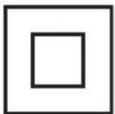
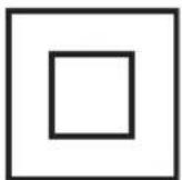
④ Double insulation (no earth wire required)
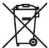
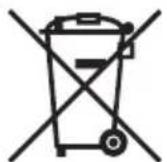
⑤ Do not dispose of electric tools and batteries together with household waste material
WHEN CONNECTING NEW 3-PIN PLUG (U.K. ONLY):
- Do not connect the blue (= neutral) or brown (= live) wire in the cord of this tool to the earth terminal of the plug
- If for any reason the old plug is cut off the cord of this tool, it must be disposed of safely and not left unattended
USE
- Preparation
- remove cable ties
- release bevel lock lever and remove styrofoam block ⑦ ! do not raise the saw blade before removing styrofoam block; this could damage the tool
- unfold the leg by pressing knob U (4x) ^8 a
- place the table saw on a flat and level surface and make sure that it is stable ⑧b
- foot V can be adjusted as shown to enhance stability ⑧c
- Assembly
- assemble the drive knob M with hex key AF ^9
- remove table insert D as shown ^①
- raise the saw blade to the highest position by rotating blade wheel S clockwise
- position the riving knife B to the highest position 1 ⑪
- assemble table insert D and lock it in place ⑩
- assemble the protective guard C as shown ^12 a, make sure that the middle part is parallel to the table top ^12 b
- check the protective guard C for proper function; it should keep in contact with the table top when changing the saw blade height and bevel settings
- check the protective guard C for proper closing before each use
! do not operate the saw if the protective guard does not move freely and close instantly
- assemble the rip fence G as shown ^13
- make sure that the lock levers are in released position
- Dust/chip extraction
- mount vacuum cleaner adapter AE as illustrated ⑭a
- connect vacuum cleaner
- alternatively, mount dust deflector Z to guide the dust into a bucket ⑭b
• Work helpers ⑮
- some sawing operations will require the use of additional work helpers
- use push block when working with narrow workpieces when you need to push close to the saw blade ⑮a
- use featherboards for all non-through-cutting operations where the protective guard cannot be used ^15 b
- push block and featherboards may be purchased at specialist woodworking stores
- Setting bevel angles ⑯
- loosen bevel lock lever R
- swing the saw to the desired bevel angle
- the saw has end stops at 0° and 45°
- to reach -2 and 47°, press release knob AO to be able to swing the saw 2° further ⑯b
- tighten the bevel lock lever R to secure the bevel setting
- Setting blade height
Set the saw blade approx. 3-6mm higher than the workpiece
- rotate blade wheel S clockwise to raise the saw blade
- rotate blade wheel S counterclockwise to lower the saw blade
- Rip fence ⑰
- the rip fence G has 3 positions ! make sure that the guiding surface is always facing the saw blade
- use position 1 in combination with the white scale
- use position 2 for maximum rip capacity in combination with the black scale
! when beveling (to the left) use the rip fence on the opposite side only (position 1 or 2)
- use position 3 for using the rip fence on the left side of the blade
- unlock rail lock lever L
- adjust the rip fence G to the desired distance with rail drive knob M
- lock rail lock lever L
! make sure that the rip fence is locked securely before sawing
- Auxiliary fence ⑱
Use the auxiliary fence H when cutting thin workpieces (18mm or less) close to the blade
- unlock rail lock lever L
- slide the rip fence G close to the blade (position 1)
- flip the auxiliary fence H and click into the highest position
- adjust the rip fence G to the desired distance with rail drive knob M
- lock rail lock lever L
- Saw table extension ⑲
- unlock rail lock lever L
- slide the rip fence G past the edge of the table (use position 2)
- flip the auxiliary fence H and click into lowest position to use as workpiece support
- adjust the rip fence G to the desired distance with rail drive knob M
- lock rail lock lever L
• Lengthways cutting (ripping)
! make sure the rip fence is locked
! when using the rip fence do not use the mitre gauge
- hold the workpiece with both hands and press it against the table ⑳
- use push stick N when the distance between the fence and the saw blade is less than 150 mm ^21
- use a push block (not standard included) when this distance is less than 50 mm ^22
- saw through the workpiece applying a uniform feed
- when cutting long boards or large panels use auxiliary work supports to support the free end ⑳
- when the workpiece is warped, place the concave side down to prevent rocking
- the workpiece must have a straight edge to face against the rip fence
- when cutting very thin workpieces (5mm or less) an auxiliary fence facing should be used ②3
- clamp a 18mm thick plywood board to the rip fence G as shown, make sure that it is resting on the table top
• Crossways cutting
- insert the mitre gauge E in one of the slots F in the table ! when beveling (to the left) use the mitre gauge on the opposite side only 25c
! when using the mitre gauge do not use the rip fence
- loosen lock knob AH ^24
- rotate the mitre gauge to the desired angle (-60° to 60°)
- tighten lock knob AH
! make sure the mitre gauge is locked
- make some trial cuts and measure if extreme accuracy is required
- hold the workpiece against the mitre gauge with one hand and place the other hand on the lock knob to guide the workpiece slowly forwards ②5
- when needed an auxiliary fence can be mounted ②6
- for repetitive cutting, a length stop block can be used ⑳
! do not use the rip fence as length stop
! make sure that the block is positioned well in front of the saw blade
• Non-through cutting ⑳
! use featherboards for all non-through-cutting operations where the protective guard cannot be used
- remove protective guard C
- set riving knife B to the middle position 2 ^1
- mount a approx. 20cm high flat facing board to the fence
- mount the featherboards (not standard included) as shown to apply pressure on the workpiece until the cut is complete
- the featherboards cannot be used when non-through cuts are performed with the mitre guage
- after finishing the cut, position the riving knife B to the highest position 1 ⑪
- assemble protective guard C
- On/off ⑲
! never stand directly in line with the saw blade ! wear hearing protection when sawing
- to turn on, press the green button
- to turn off, press the paddle
! in case of current interruption or when the plug is accidentally pulled out, the tool will not restart on its own
- Changing saw blade ③0
! disconnect the plug
! wear gloves when handling saw blades
! for correct functioning of the riving knife it is important to use the correct saw blade ③0a
- raise the saw blade to the highest position by rotating blade wheel S clockwise
- remove protective guard C
- remove table insert D
- take both wrenches AC from storage
- use the open wrench to hold the shaft and the ring wrench to loosen the blade nut AM COUNTER CLOCKWISE (= in same direction as arrow printed on saw blade) ③0b
- remove flange AL and saw blade
- unlock riving knife locking lever AN
! change saw blade with saw teeth pointing down at the front of the table
- mount flange AL
- use the open wrench to hold the shaft and the ring wrench to tighten the blade nut AM CLOCKWISE
- unlock riving knife locking lever AN
- install table insert D
- install protective guard C
- Checking/adjusting of 90^ blade alignment! disconnect the plug
- raise the saw blade to the highest position by rotating blade wheel S clockwise
- release bevel lock lever R
- swing the saw to the 90° end stop (indicator shows 0°)
- lock bevel lock lever R
- check for a 90° angle between blade and table with a square ③1
- if necessary, adjust the 90^ blade alignment as follows ③
-
loosen end stop screw AK with a blade wrench 10 (not standard included)
-
release bevel lock lever R
-
set saw blade to 90° angle between blade and table
-
lock bevel lock lever R
-
adjust end stop until it touches release knob AO
-
tighten end stop screw AK
-
reset the bevel indicator Q to 0°
- Checking/adjusting of 45^ blade alignment
! disconnect the plug
- raise the saw blade to the highest position by rotating blade wheel S clockwise
- release bevel lock lever R
- swing the saw to the 45^ end stop (indicator Q shows 45^ )
- lock bevel lock lever R
- check for a 45^ angle between blade and table with a mitre square ③2
- if necessary, adjust the 45^ end stop screw AJ in the same way as for 90^ angle
- Checking/adjusting parallelism blade – mitre gauge slots ③4
! disconnect the plug
- raise the saw blade to the highest position by rotating blade wheel S clockwise
- mark a point on the saw blade body
- set a combination square to the edge of the mitre gauge slot and the ruler touching the marked point
- rotate the saw blade and check the marked point at the rear of the table
- if both measurements are not identical, adjust as follows ③5:
-
loosen wing nut AP
-
turn bolt AQ clockwise or counterclockwise until the blade is parallel to the mitre gauge slot
-
tighten wing nut AP
- Checking/adjusting rip fence
! disconnect the plug
! make sure that the checks/adjustments mentioned above are performed before performing this adjustment
! the rip fence must be parallel to the saw blade to prevent kick back
- raise the saw blade to the highest position by rotating blade wheel S clockwise
- remove protective guard C
- lock the rip fence G to position 1⑰
- slide the fence to touch the blade and lock it
- the blade should contact the fence front to back
- if not, loosen the fence post (front and/or back) and slide it left or right (5mm hex, not standard included)
- firmly tighten the fence posts
- loosen the indicator K and slide it left or right to align with 0 on the white scale ⑰
- tighten the indicator K
- lock the rip fence G to position 2⑰
- measure the distance from the blade (front and back) to the fence
- both measurements should be 101.6mm
- if not, loosen the fence post (front and/or back) and slide it left or right
- firmly tighten the fence posts
- lock the rip fence G to position 3 ^17
- slide the fence to touch the blade and lock it
- the blade should contact the fence front to back
- if not, loosen the fence post (front and/or back) and slide it left or right
- firmly tighten the fence posts
- assemble protective guard C
! make a few test cuts with scrap material to check the adjustments
- Checking/adjusting riving knife ③6
! disconnect the plug
! make sure that the checks/adjustments mentioned above are performed before performing this adjustment
! regularly check the alignment of the riving knife
- raise the saw blade to the highest position by rotating blade wheel S clockwise
- remove protective guard C
- check the spacing between fence and blade body on both sides of the blade, while the blade teeth are touching the fence
- 3 paper thicknesses should fit between the blade body and the rip fence G
- if not, adjustment is needed ^37
-
remove table insert D
-
loosen the clamp screws (5mm hex, not standard included)
-
reposition the riving knife B as needed
-
firmly tighten the clamp screws
-
check the alignment and spacing again and repeat
- Adjusting table insert ③8
- the front of the table insert should be flush or a little below the saw table; the back should be flush or a little above the saw table
- if needed, the table insert can be adjusted with the 4 set screws (2.5mm hex, not standard included)
- Storage/transport
- to store the tool make sure that the end of the rail is not extruding from the table top side ⑲a
- set the riving knife B in the middle position 2
- lower the saw blade
- wrap the cable around the cable storage hook X
- fold the legs and place the tool in an upright position ③9b
- lift the tool by grasping the transport handle AB with the table top facing towards you
- the removable components of the tool can be stored as shown ④0a-e
APPLICATION ADVICE
- Only use sharp saw blades of the correct type
- quality of cut improves by the number of teeth
- carbide tipped blades stay sharp up to 30 times longer than ordinary blades
MAINTENANCE / SERVICE
- Always keep tool and cord clean (especially the ventilation slots at the back-end of the motor housing) ! disconnect the plug before cleaning
- Occasionally clean the area under the saw blade (dust chute) to prevent dust accumulation
- Clean saw blade immediately after use (especially from resin and glue)
! the saw blade becomes very hot during use; do not touch it before it has cooled down
- Occasionally oil the points indicated ④ with SAE 20/SAE 30 or WD40
- If the tool should fail despite the care taken in manufacturing and testing procedures, repair should
be carried out by an after-sales service centre for SKIL power tools
- send the tool undismantled together with proof of purchase to your dealer or the nearest SKIL service station (addresses as well as the service diagram of the tool are listed on www.skil.com)
- Be aware that damage due to overload or improper handling of the tool will be excluded from the warranty (for the SKIL warranty conditions see www.skil.com or ask your dealer)
ENVIRONMENT
- Do not dispose of electric tools, batteries, accessories and packaging together with household waste material (only for EU countries) in observance of European Directive 2012/19/EC on waste of electric and electronic equipment and its implementation in accordance with national law, electric tools that have reached the end of their life must be collected separately and returned to an environmentally compatible recycling facility
- symbol⑤ will remind you of this when the need for disposing occurs
NOISE
- Measured in accordance with EN 62841 the sound pressure level of this tool is 93.0 dB(A) and the sound power level 108.0 dB(A) (uncertainty K = 3 dB)
- The noise emission level has been measured in accordance with a standardised test given in EN 62841; it may be used to compare one tool with another and as a preliminary assessment of exposure to noise when using the tool for the applications mentioned
- using the tool for different applications, or with different or poorly maintained accessories, may significantly increase the exposure level
- the times when the tool is switched off or when it is running but not actually doing the job, may significantly reduce the exposure level
F
Table de sciage 1340
INTRODUCTION
- Stockage/transport
WAARSCHUWINGEN MET BETREKKING TOT AFSCHERMING
WAARSCHUWINGEN MBT ZAAGPROCEDURES
WAARSCHUWINGEN MBT WERKPROCEDURE TAFELZAAG
1) SIKKERHET PÅ ARBEIDSPLASSEN
- Kutte overlangs (rippe)
VEDLIKEHOLD / SERVICE
- retire as abraçadeiras dos cabos
Z Vychyl'ovač prachu
AA Miesto na uloženie vychyl'ovača prachu
AB Prepravná rúčka
AC Kl'úče
ĎALŠIE BEZPEČNOSTNÉ POKYNY
DODATNA UPUTSTVA O SIGURNOSTI
SAEPINKIDE OHUTUSJUHISED
KAITSMISEGA SEOTUD HOIATUSED
APKALPOŠANA / APKOPE
TECHNINIAI DUOMENYS ①
PRIETAISO ELEMENTAI⑥
natural_image
Simple line drawing of a pencil (no text or symbols)
natural_image
Simple line drawing of a pencil (no text or symbols)
natural_image
Simple line drawing of a pencil (no text or symbols)محفظه موتورا
! رق بکشید
• ۱۲۵
گھگاه تیز کنید
تیغه اره را فورا
کنید
• پاک
د شدن به!
أنها دست نزنید
natural_image
Technical line drawing of a mechanical assembly with a magnified inset showing internal components (no text or symbols)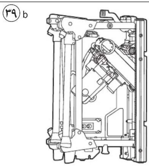
natural_image
Technical line drawing of a mechanical assembly with no visible text or symbols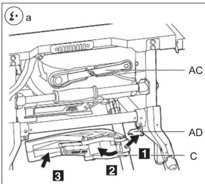
text_image
a AC AD C 1 2 3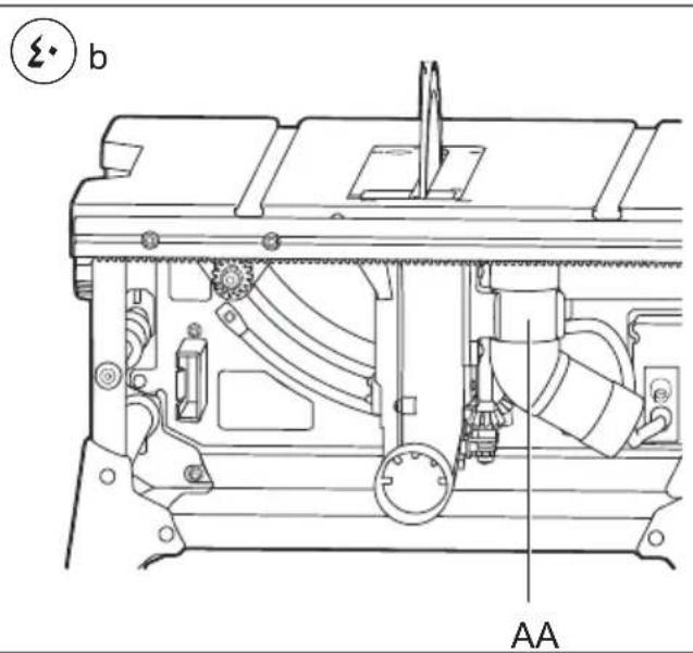
text_image
b AA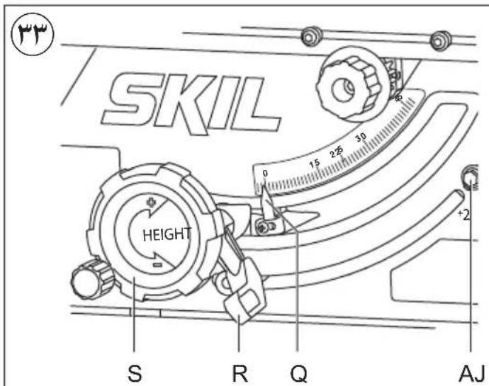
text_image
SKIL HEIGHT S R Q AJ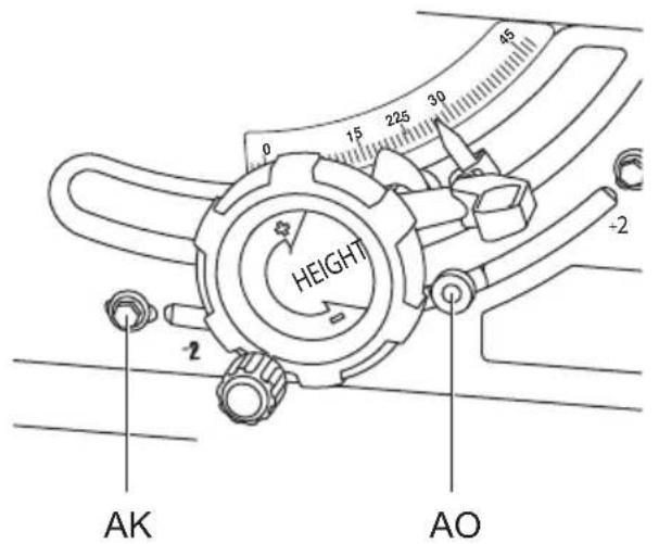
text_image
HEIGHT AK AO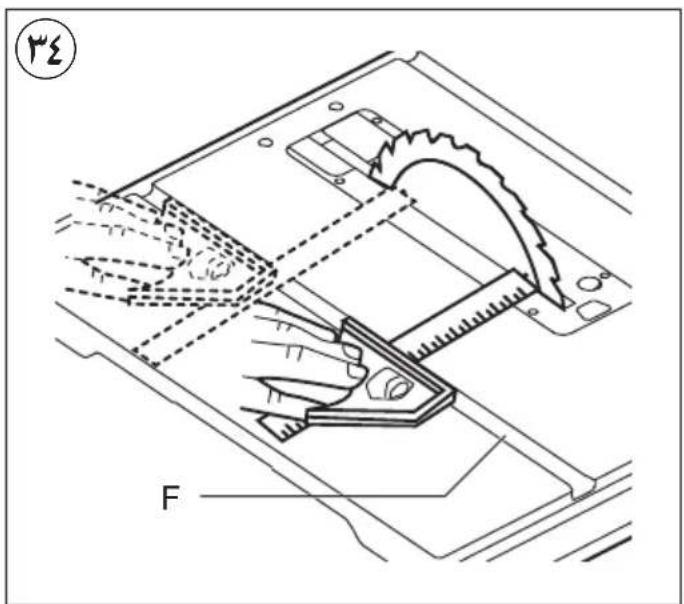
text_image
F 3/2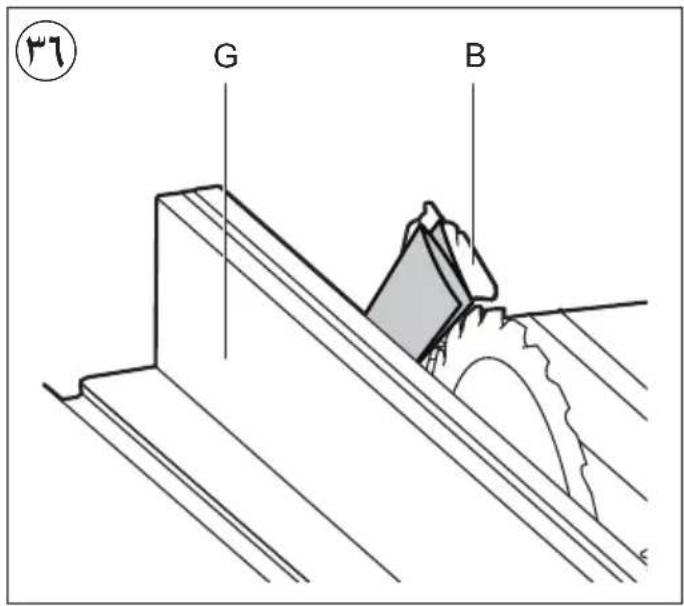
text_image
G B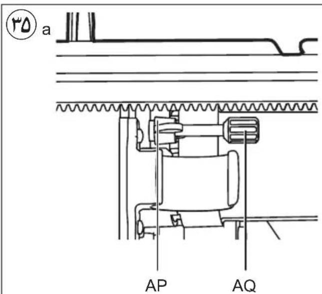
text_image
a AP AQ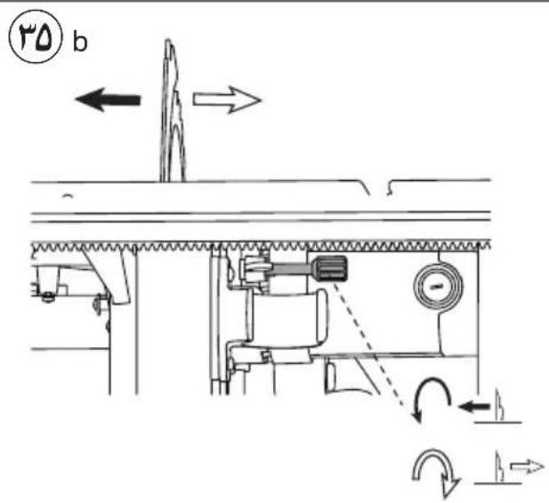
text_image
b b
text_image
19 T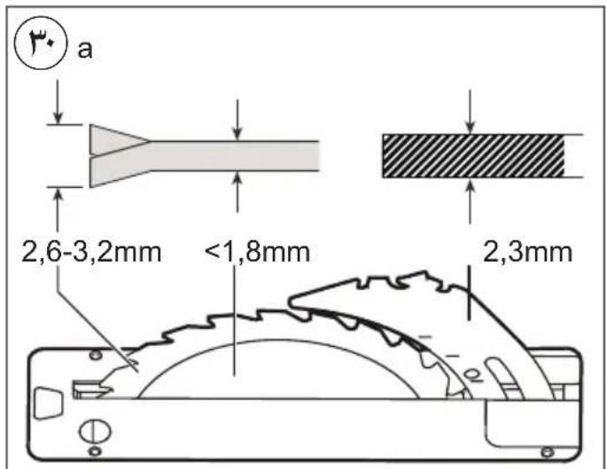
text_image
a 2,6-3,2mm <1,8mm 2,3mm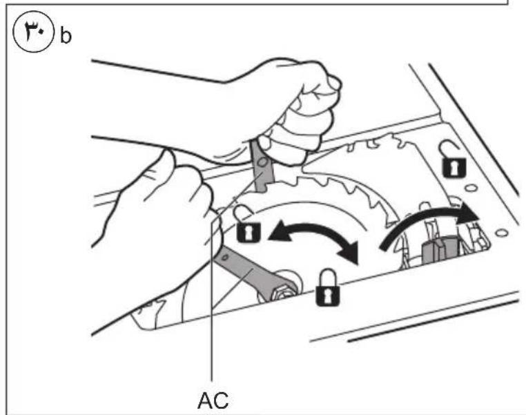
text_image
b AC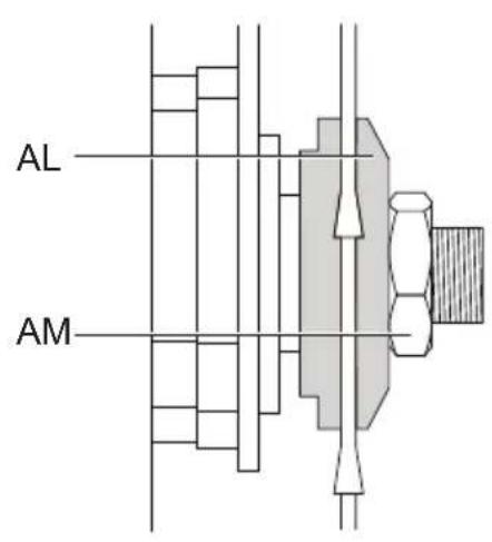
text_image
AL AM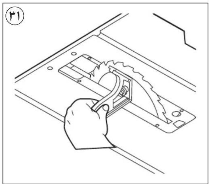
natural_image
Line drawing of a hand using a tool to cut or install a mechanical component, no text or symbols present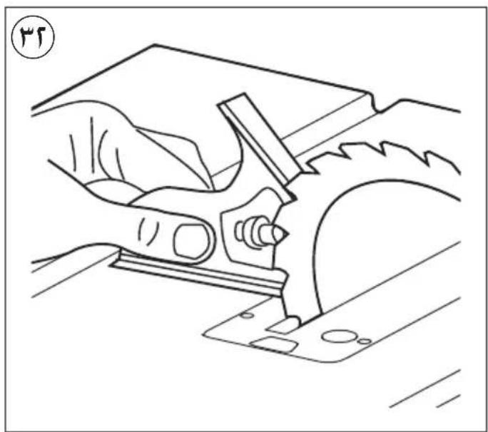
natural_image
Line drawing of a hand operating a mechanical tool on a workbench (no text or symbols)natural_image
Mechanical assembly diagram showing a lever mechanism and a close-up of a component (no text or symbols present)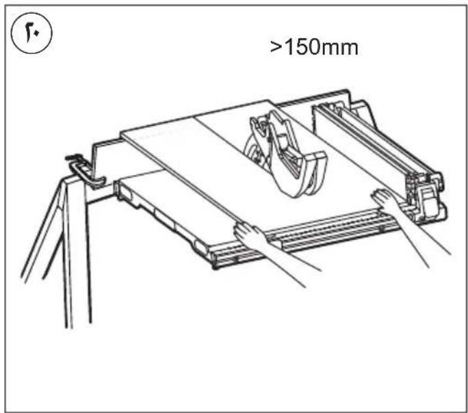
text_image
>150mm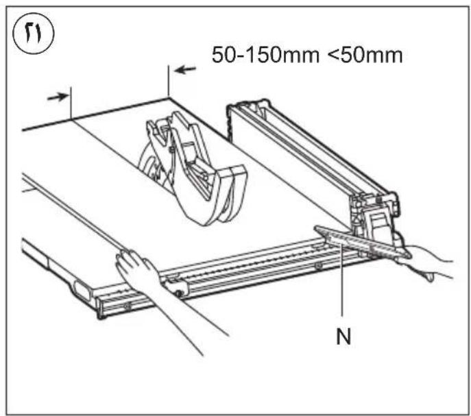
text_image
50-150mm <50mm N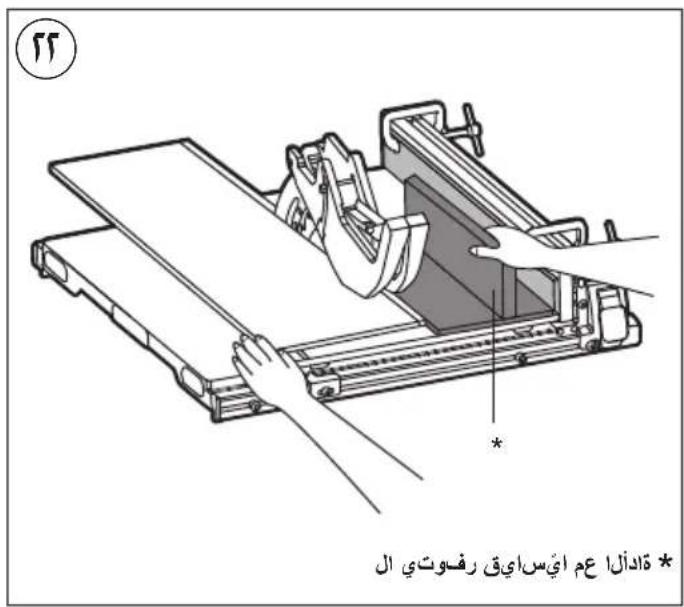
text_image
تَادُلَى عَمَّ أَيْسَ ايْقِ رفُوتِي ال *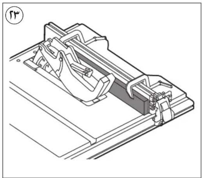
natural_image
Technical line drawing of a mechanical assembly with no visible text or symbols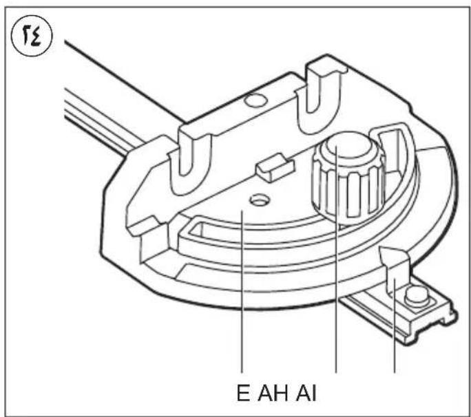
text_image
E AH AI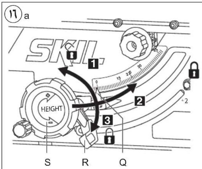
text_image
11 a SKIL. 1 0 15 25 30 2 Height 2 3 S R Q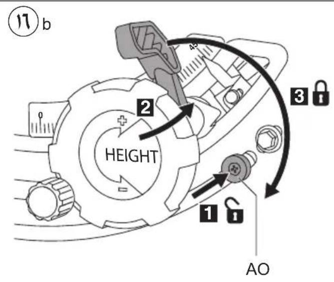
text_image
17 b 2 HEIGHT 3 1 AO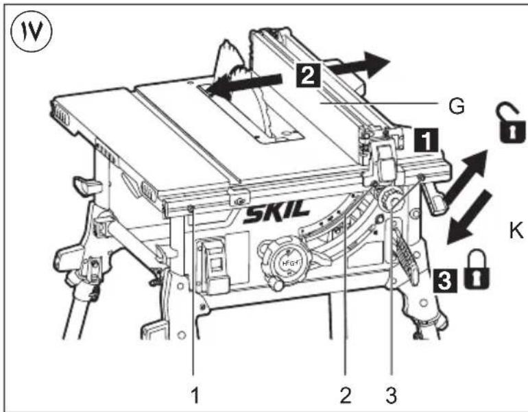
text_image
IV 2 G 1 SKIL HFD-1 K 3 1 2 3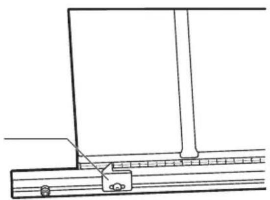
natural_image
Technical line drawing of a mechanical assembly with a bracket and rail (no text or symbols)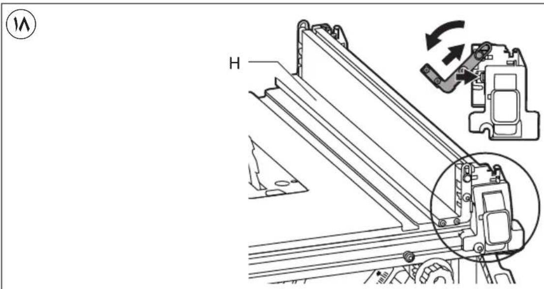
text_image
Technical diagram showing mechanical assembly with labeled component H and a magnified inset view of a device's internal structure.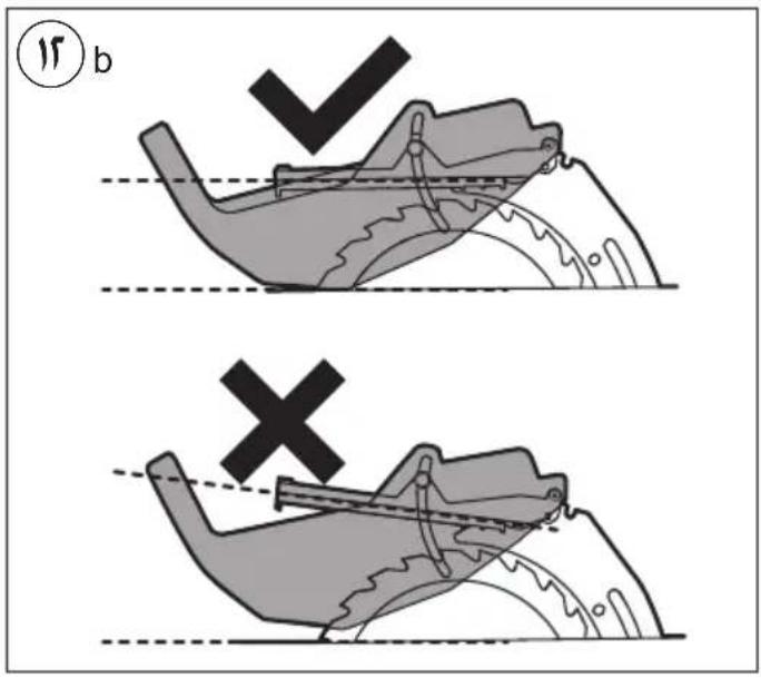
text_image
17 b ×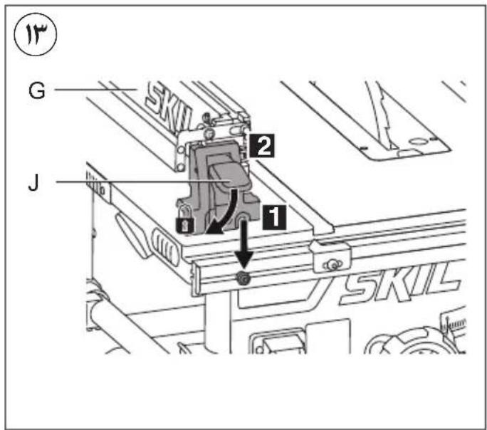
text_image
G J 2 1 SKIL SKIL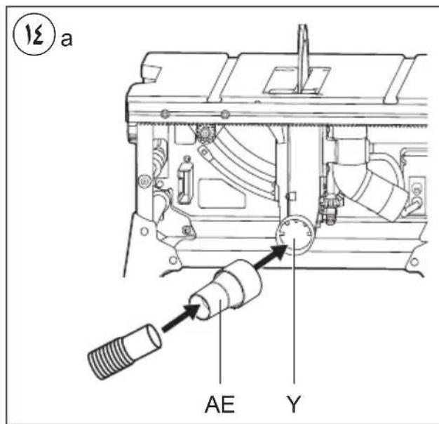
text_image
13 a AE Y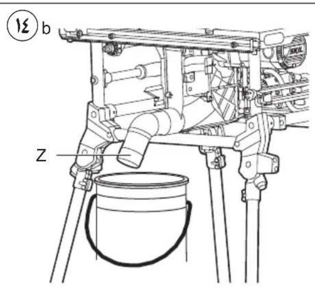
text_image
12 b Z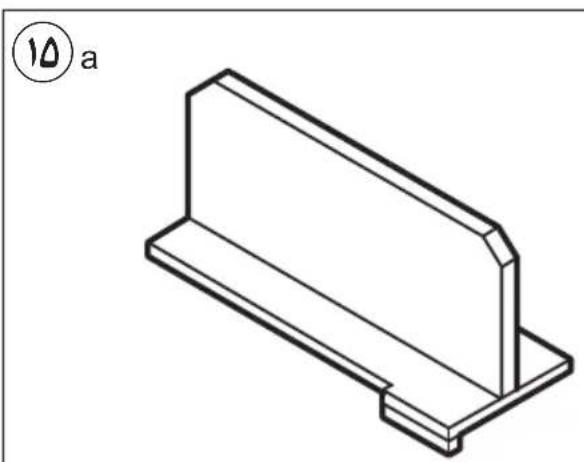
natural_image
Isometric line drawing of a rectangular metal bracket with a flat top and base (no text or symbols)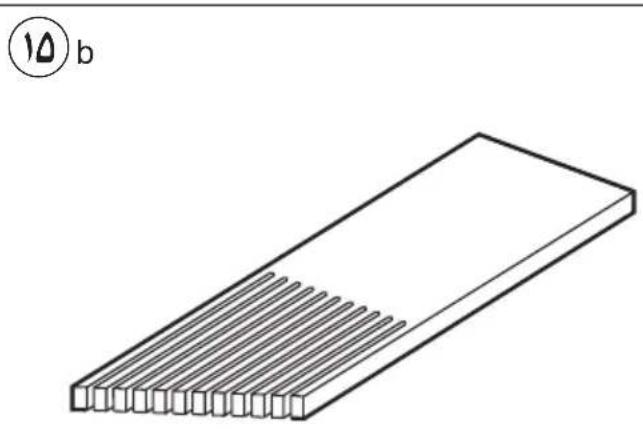
natural_image
Isometric line drawing of a rectangular block with parallel grooves, no text or symbols presenttext_image
1 b AE C G Z E N M AF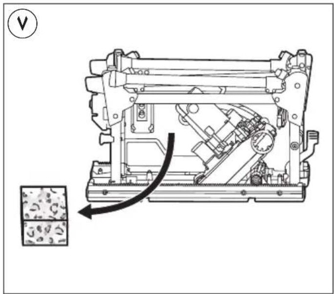
text_image
Technical diagram of a mechanical device with an arrow indicating force or movement, accompanied by a magnified inset showing internal components.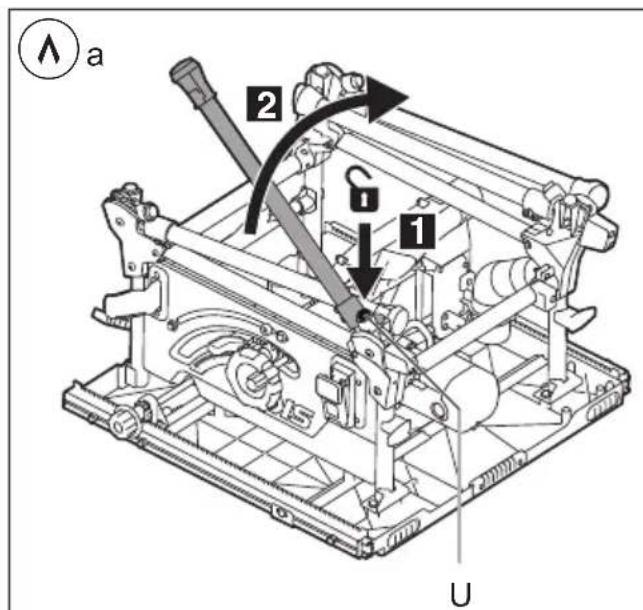
text_image
a 2 G 1 U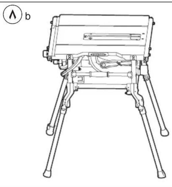
natural_image
Technical line drawing of a tripod-mounted device with visible wiring and mounting feet (no text or symbols)
text_image
C 1 2 3 V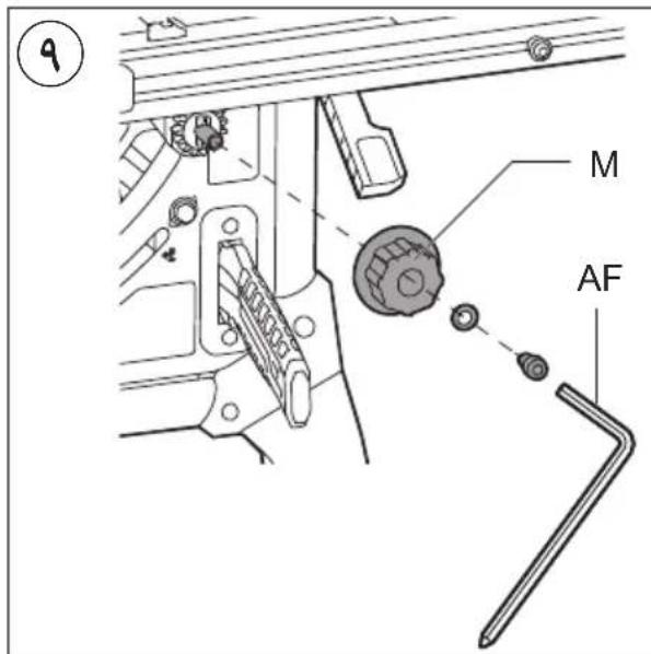
text_image
M AF1
1340

text_image
90 mm 90°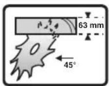
text_image
63 mm 45°1
natural_image
Silhouette of a person using a document inside a circle (no text or symbols)F

natural_image
Icon of a person wearing headphones inside a circle (no text or symbols)③
①
①a
ADBCEHGJ
text_image
X W U V AG T S R Q P K L M N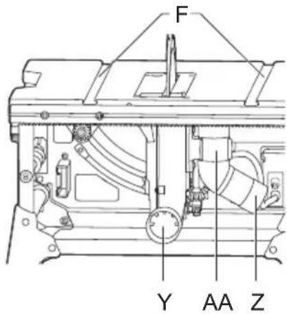
text_image
F Y AA Z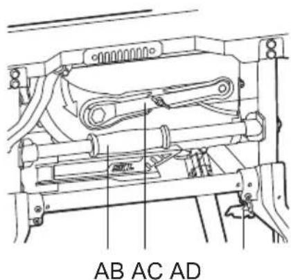
text_image
AB AC ADمنشار المنضدة
1340
SKIL®
natural_image
Technical line drawing of a SKIL robotic platform with tripod legs and base plate (no text or symbols)
text_image
دليل الاستعمال AR راهنماي اصلی FA