
3590 AA - Saw SKIL - Free user manual and instructions
Find the device manual for free 3590 AA SKIL in PDF.

| Product type | Cordless sliding miter saw |
| Brand | Skil |
| Model | 3590 AA |
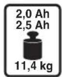
| Power source | 20 V lithium-ion battery (BR1*31**** models) |
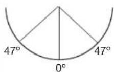
| Miter angle | From -47° to +47° |
| Bevel angle | From 0° to 45° (left) |
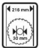
| Blade type | Circular saw blade, diameter 254 mm (10"), bore 30 mm |
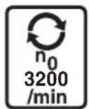
| No-load speed | Approximately 4000 rpm |
| Weight | Approximately 15 kg |
| Dimensions (L x W x H) | Approximately 60 x 50 x 40 cm |
| Main functions | Straight cut, miter cut, bevel cut, compound cut, sliding cut, grooving |
| Safety | Lower guard, safety switch (lever), spindle lock, automatic blade brake, accidental start protection |
| Dust extraction | Integrated dust bag, adaptable to vacuum cleaner |
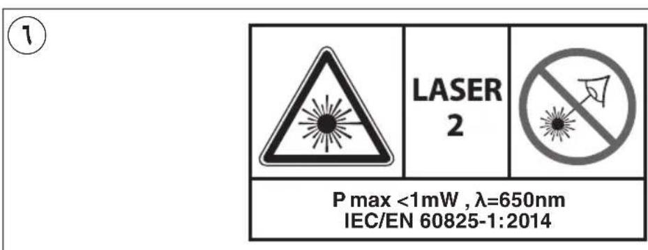
| Guide laser | Class 2 laser line, horizontally adjustable |
| Included accessories | Dust bag, clamp, hex key, additional table insert |
| Maintenance | Regularly clean ventilation slots, check guard, clean blade after use, clean laser outlet |
| Repairability | Repair by Skil after-sales service, spare parts available at www.skil.com |
| Warranty | See conditions at www.skil.com or from retailer |
| Intended use | Longitudinal and cross cutting of wood, non-professional use |
Frequently Asked Questions - 3590 AA SKIL
User questions about 3590 AA SKIL
0 question about this device. Answer the ones you know or ask your own.
Ask a new question about this device
Download the instructions for your Saw in PDF format for free! Find your manual 3590 AA - SKIL and take your electronic device back in hand. On this page are published all the documents necessary for the use of your device. 3590 AA by SKIL.
USER MANUAL 3590 AA SKIL
natural_image
Technical illustration of a mechanical cutting machine with visible blades and levers (no text or symbols)
GB ORIGINAL INSTRUCTIONS 17
(F) NOTICE ORIGINALE 23
D ORIGINALBETRIEBSANLEITUNG 31
NL ORIGINELE GEBRUIKSAANWIJZING 39
S BRUKSANVISNING I ORIGINAL 46
DK ORIGINAL BRUGSANVISNING 53
N ORIGINAL BRUKSANVISNING 60
FIN ALKUPERÄISET OHJEET 66
(E) MANUAL ORIGINAL 73
(P) MANUAL ORIGINAL 81
I ISTRUZIONI ORIGINALI 88
H EREDETI HASZNÁLATI UTASÍTÁS 96
CZ PÚVODNÍM NÁVODEM K POUŽÍVÁNÍ 103
TR ORIJINAL İŞLETME TALİMATI 110
PL INSTRUKCJA ORYGINALNA 117
RU ПОДЛИННИК РУКОВОДСТВА ПО 125
ЭКСПЛУАТАЦИИ
UA ОРИГІНАЛЬНА ІНСТРУКЦІЯ 133
З ЕКСПЛУАТАЦІЇ
GR ΠΡΩΤΟΥΠΟ ΟΔΗΓΙΩΝ ΧΡΗΣΗΣ 141
RO INSTRUCTIUNI DE FOLOSIRE 150
ORIGINALE
BG ОРИГИНАЛНО РЪКОВОДСТВО 158
ЗА ЕКСПЛОАТАЦИЯ
SK PÔVODNÝ NÁVOD NA POUŽITIE 166
HR ORIGINALNE UPUTE ZA RAD 173
SRB ORIGINALNO UPUTSTVO ZA RAD 179
SLO IZVIRNA NAVODILA 186
EST ALGUPÄRANE KASUTUSJUHEND 193
LV ORIGINĀLĀ LIETOŠANAS PAMĀCĪBA 200
LT ORIGINALI INSTRUKCIJA 207
МК ИЗВОРНО УПАТСТВО ЗА РАБОТА 214
AL UDHËZIMET ORIGJINALE 222
AR دليل الاستعمال 243
④ RAHENMAI AUSLI 238

EAC
www.skil.com

| GB | EU Declaration of conformityCordless sliding mitre saw Article number | We declare under our sole responsibility that the stated products comply with all applicable provisions of the directives and regulations listed below and are in conformity with the following standards.Technical file at:* |
| F | Déclaration de conformité UEScie à onglet coulissantesans fil Numéro d'article | Nous déclarons sous notre propre responsabilité que les produits décrits sont en conformité avec les directives, règlements normatifs et normes énumérés ci-dessous.Dossier technique auprès de:* |
| D | EU-KonformitätserklärungAkku-Gehrungssägemit Gleitfunktion Sachnummer | Wir erklären in alleiniger Verantwortung, dass die genannten Produkte allen einschlägigen Bestimmungen der nachfolgend aufgeführten Richtlinien und Verordnungen entsprechen und mit folgenden Normen übereinstimmen.Technische Unterlagen bei:* |
| NL | EU-conformiteitsverklaringDraadloze afkort-trekzaag Productnummer | Wij verklaren op eigen verantwoordelijkheid dat de genoemde producten voldoen aan alle desbetreffende bepalingen van de hierna genoemde richtlijnen en verordningen en overeenstemmen met de volgende normen.Technisch dossier bij:* |
| S | EU-konformitetsförklaringSladdlös glidande geringssåg Produktnummer | Vi förklarar under eget ansvar att de nämnda produkterna uppfyller kraven i alla gällande bestämmelser i de nedan angivna direktiven och förordningarnas och att de stämmer överens med följande normer.Teknisk dokumentation:* |
| DK | EU-overensstemmelseserklæringBatteridrevet glidendegeringssav Typenummer | Vi erklærer som eneansvarlige, at det beskrevne produkt er i overensstemmelse med alle gældende bestemmelser i følgende direktiver og forordninger og opfylder følgende standarder.Tekniske bilag ved:* |
| N | EU-samsvarserklæringBatteriløs glidende gjæringssag Produktnummer | Vi erklærer under eneansvar at de nevnte produktene er i overensstemmelse med alle relevante bestemmelser i direktivene og forordningene nedenfor og med følgende standarder.Teknisk dokumentasjon hos.* |
| FIN | EU-vaatimustenmukaisuusvakuutusAkkukäyttöinenliukuva jiirisaha Tuotenumero | Vakuutamme täten, että mainitut tuotteet vastaavat kaikkia seuraavien direktiivien ja asetusten asiaankuuluvia vaatimuksia ja ovat seuraavien standardien vaatimusten mukaisia.Tekniset asiakirjat saatavana:* |
| E | Declaración de conformidad UESierra ingletadora deslizante inalámbrica Número de artículo | Declaramos bajo nuestra exclusiva responsabilidad, que los productos nombrados cumplen con todas las disposiciones correspondientes de las directivas y los reglamentos mencionados a continuación y están en conformidad con las siguientes normas.Documentos técnicos de:* |
| P | Declaração de conformidade CESerra de esquadriadeslizante sem fios Número do produto | Declaramos sob nossa exclusiva responsabilidade que os produtos mencionados cumprem todas as disposições e os regulamentos indicados e estão em conformidade com as seguintes normas.Documentação técnica pertencente à:* |
| I | Dichiarazione di conformità UETroncatrice scorrevolecordless Codice prodotto | Dichiariamo sotto la nostra piena responsabilità che i prodotti indicati sono conformi a tutte le disposizioni pertinenti delle direttive e dei regolamenti elencati di seguito, nonché alle seguenti normative.Documentazione tecnica presso:* |
| H | EU konformitási nyilatkozatAkkus csúsztathatógérvágó fűrész Cikkszám | Egyedüli felelőséggel kijelentjük, hogy a megnevezett termékek megfelelnek az alábbiakban felsorolásra kerülő irányelvek és rendeletek valamennyi idevágó előírásainak és megfelelnek a következő szabványoknak.Műszaki dokumentumok megőrzési pontja:* |
| CZ | EU prohlásení o shoděAkumulátorová posuvná pokosová pila Objednaci číslo | Prohlašujeme na výhradní zodpovědnost, že uvedený výrobek splňuje všechna příslušná ustanovení níže uvedených směrnic a nařízení a je v souladu s následujícimi normami.Technické podklady u:* |
| TR | AB Uygunluk beyaniKablosuz kayar gönyetestere Urün kodu | Tek sorumlu olarak, tanimlanan ürünün aşağıdaki yönetmelik ve direktiflerin geçerli bütün hükümlerine ve așağıdaki standartlara uygun olduğunu beyan ederiz.Teknik belgelerin bulunduğu yer:* |
| PL | Deklaracja zgodności UEAkumulatorowa piłaukośnica przesuwna Numer katalogowy | Oświadczamy z pełną odpowiedzialnością, że niniejsze produkty odpowiadają wszystkim wymaganiom poniżej wyszczególnionych dyrektyw i rozporządzeń, oraz że są zgodne z następującymi normami.Dokumentacja techniczna:* |
| RU | Заявление о соответствии ЕСАккумуляторная раздвижная усовочная пила Товарный номер | Мы заявляем под нашу единоличную ответственность, что названные продукты соответствуют всем действующим предписаниям нижеуказанных директив и распоряжений, а также нижеуказанных норм.Техническая документация хранится y:* |
| UA | Заява про відповідність ЄСАкумуляторна розсувна торцювальна пила Товарний номер | Мизаявляемо під нашу одноособову відповідальність, що названі вироби відповідають усім чинним положенням нищеозначених директив і розпоряджень, а також никчеозначеним нормам.Технічна документація зберігається y:* |
| GR | Δήλωση πιστότητας EEАσύρματο συρόμενοφαλτσοπρίονο | Арібмός ευρετηρίου | Δηλώνουμε με αποκλειστική μας ευθύνη, ότι τα αναφερόμενα προϊόντα αντιστοιχούν σε όλες τις σχετικές διατάξεις των πιο κάτω αναφερόμενων οδηγιών και κανονισμών και ταυτίζονται με τα ακόλουθα πρότυπα.Техνικά έγγραφα στη.* |
| RO | Declarație de conformitate UEFerăstrău circular culisant fără fir | Număr de identificare | Declarăm pe proprie răspundere că produsele menționate corespund tuturor dispozitiilor relevante ale directivelor și reglementărilor enumerate în cele ce urmează și sunt în conformitate cu următoarele standarde.Documentație tehnică la:* |
| BG | EC декларация за съответствиеАкумулаторен плъзгащ се трион за рязане под ъгъл | Каталожен номер | С пълна отговорност ние декларираме, че посочените продукти отговарят на всички валидни изисквания на директивите и разпоредбите по-долу и съответства на следните стандарти.Техническа документация при:* |
| SK | Pôvodnej EU vyhlásenie o zhodeAkumulátorová posuvná pokosová píla Vecné číslo | Vyhlasujeme na výhradnú zodpovednosť, že uvedený výrobok splňa všetky príslušné ustanovenia nižšie uvedených smernic a nariadení a je v súlade s nasledujúcimi normami.Technické podklady má spoločnosť:* | |
| HR | EU izjava o sukladnostiAkumulatorska klizna preklopna nagibna pila Kataloški broj | Pod punom odgovornošću izjavljujemo da navedeni proizvodi odgovaraju svim relevantnim odredbama direktiva i propisima navedenima u nastavku i da su sukladni sa sljedećim normama.Tehnička dokumentacija se može dobiti kod:* | |
| SRB | EU-izjava o usaglašenostiBežična klizna ugaona testera Broj predmeta | Na sopstvenu odgovornost izjavljujemo, da navedeni proizvodi odgovaraju svim dotičnim odredbama naknadno navedenih smernica u uredaba i da su u skladu sa sledećim standardima.Tehnička dokumentacija kod:* | |
| SLO | Izjava o skladnosti ES Brezžična drsna zajeralna žaga Številka artikla | Izjavljamo pod izključno odgovornostjo, da je omenjen izdelek v skladu z vsemi relevantnimi določili direktiv in uredb ter ustreza naslednjim standardom.Tehnična dokumentacija pri:* | |
| EST | EL-vastavusdeklaratsioonJuhtmeta liugnurgasaag Tootenumber | Kinnitame ainuvastutajatena, et nimetatud tooted vastavad järgnevalt loetletud direktiivide ja määruste köikidele asjaornastele nöutele ja on kooskõlas järgmiste normidega.Tehnilised dokumendid saadaval:* | |
| LV | Deklarăcija par atbilstību EK standartiemBezvadu slīdrāmja lenkzāgis Izstrādājuma numurs | Mēs ar pilnu atbildību paziņojam, ka šeit aplūkotie izstrādājumi atbilst visiem tālāk minētajās direktīvās un rīkojumos ietvertajām saistošajām nostādnēm, kā arī sekojošiem standartiem.Tehniska dokumentacija no:* | |
| LT | ES atitikties deklaracija Belaidis slankus jžambinis pjūklas Gaminio numeris | Atsakingai pareiškiame, kad išvardyti gaminiai atitinka visus privalomus žemiau nurodytu direktyvu ir reglamentų reikalavimus ir šiuos standartus.Techninė dokumentacija saugoma:* | |
| MK | EU-Изјава за сообразностБезжична клизна пила за косо сечење Број на артикл | Со целосна одговорност изјавуваме, дека опишаните производи се во согласност со сите релевантни одредби на следните регулативи и прописи и се во согласност со следните норми.Техничка документација кај:* | |
| AL | EU Deklarata e konformitetitSharrë rrèshqitëse këndesh me bateri Numri i nenit | Ne deklarojmě me përgjegjësinė tonė të vetme se produktet e paraqitura janė në përputhje me të gjitha dispozitat e zbatueshme të direktivave dhe rregulloreve të listuara më poshtë dhe janë në përputhje me standardet si më poshtë.Dosja teknike nė:* | |
| 3590 BT1*3590** | 2006/42/EC EN 62841-1:20152014/30/EU EN 62841-3-9:2020 + A11:20202011/65/EU EN 60825-1:2014EN 55014-1: 2021EN 55014-2: 2021EN 63000:2018 | ||
| SKIL *Skil BVRithmeesterpark 22 A14838 GZ BredaThe Netherlands | |||
| Olaf DijkgraafApproval ManagerSkil BV, Rithmeesterpark 22 A1, 4838 GZ Breda, NL04.11.2022 |
| Declaration of ConformityCordless sliding mitre saw Article number | We declare under our sole responsibility that the stated products comply with all applicable provisions of the directives and regulations listed below and are in conformity with the following standardsTechnical file at:Chervon Europe Ltd., 34 Bridge Street, Reading, RG1 2LU, United Kingdom |
| 3590 BT1*3590** | Supply of Machinery (Safety) Regulations 2008 (SI 2008/1597)Electromagnetic Compatibility Regulations 2016 (SI 2016/1091)The Restriction of the Use of Certain Hazardous Substances in Electrical and Electronic Equipment Regulations 2012 (SI 2012/3032)EN 62841-1:2015EN 62841-3-9:2020 + A11:2020EN 60825-1:2014EN 55014-1: 2021EN 55014-2: 2021EN IEC 63000:2018 |
 Chervon Europe Ltd., 34 Bridge Street, Reading, RG1 2LU, United Kingdom, as authorized representative (in terms of above regulations) acting on behalf of Skil BV, Rithmeesterpark 22 A1, 4838GZ Breda, The Netherlands Chervon Europe Ltd., 34 Bridge Street, Reading, RG1 2LU, United Kingdom, as authorized representative (in terms of above regulations) acting on behalf of Skil BV, Rithmeesterpark 22 A1, 4838GZ Breda, The Netherlands | |
James McCroryTechnical Service Manager Place of issue: ReadingDate of issue: 04/11/2022 Place of issue: ReadingDate of issue: 04/11/2022 |
①
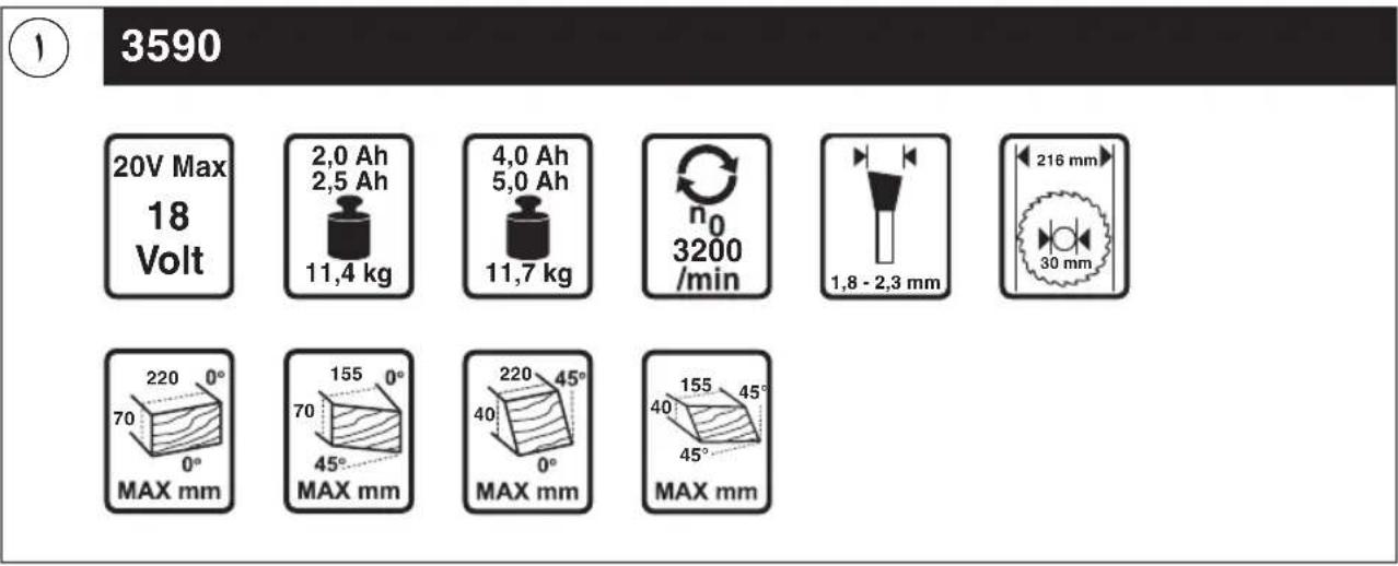
3590


②

③

natural_image
Icon of a person wearing headphones and glasses, enclosed in a black circle (no text or symbols)4

natural_image
Black circular sign with a diagonal line crossing over two hands (no text or symbols)5
natural_image
Symbol of a trash bin crossed with no text or labels⑥
⑦ a
⑦b

11
⑪ c d e1 ⑪
natural_image
Silhouette of a human figure holding a mechanical device (no text or symbols visible)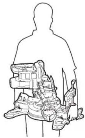
natural_image
Silhouette of a person holding a device with internal components, no text or symbols visible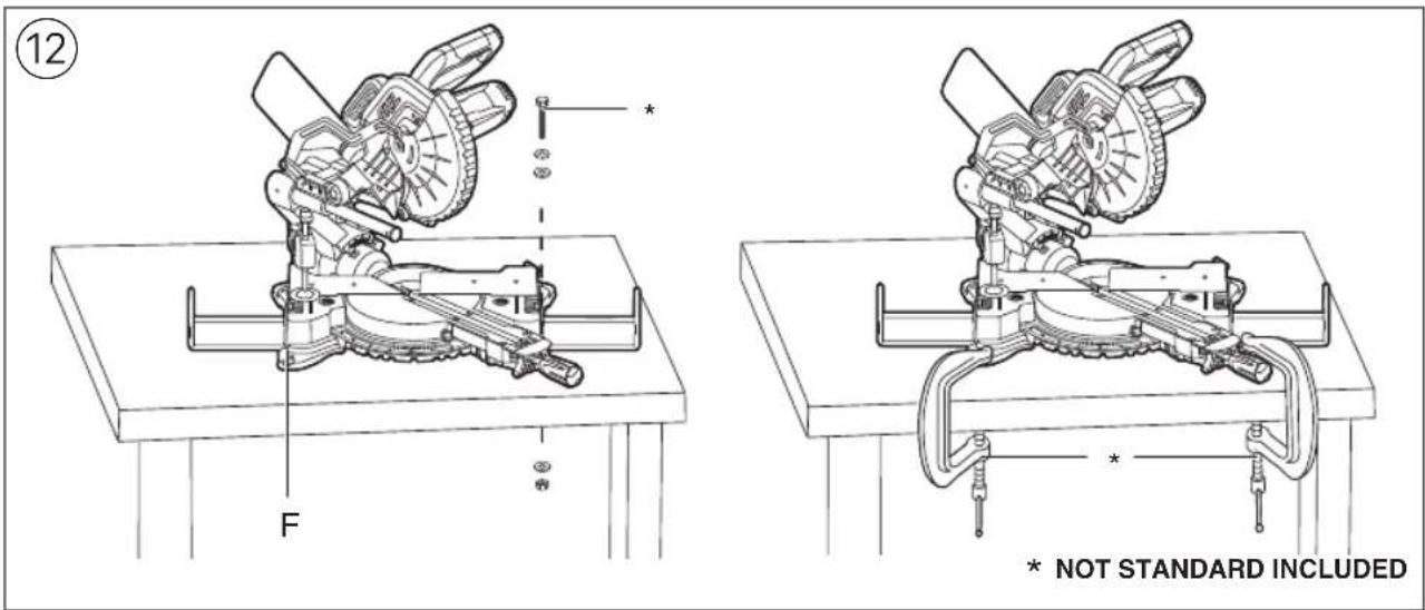
16
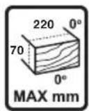
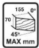
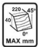
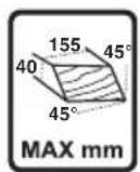
 | 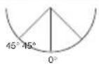 | Max A x Max B | |
| 0° 0° | 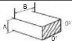 | 70 x 220 mm | |
| 45° 0° | 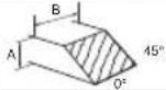 | 40 x 220 mm | |
| 0° 45° | 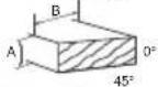 | 70 x 155 mm | |
| 45° 45° | 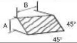 | 40 x 155 mm |
⑰a
natural_image
Technical line drawing of a mechanical cutting machine (no text or symbols)⑰b
⑱ a ⑱ b

natural_image
Technical line drawing of a mechanical cutting tool with wooden base and saw (no text or symbols)
natural_image
Technical line drawing of a mechanical assembly with no visible text or symbols


26
28

natural_image
Technical line drawing of a mechanical assembly with no visible text or symbols
natural_image
Technical line drawing of a mechanical assembly with no visible text or symbols* NOT STANDARD INCLUDED
29 a
natural_image
Mechanical assembly diagram showing gear and linkage components (no text or labels)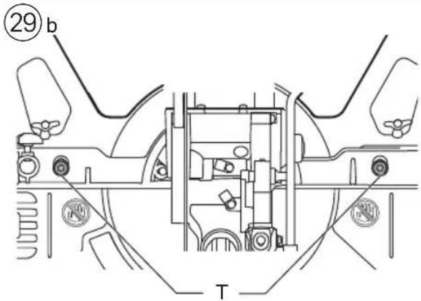
* NOT STANDARD INCLUDED
natural_image
Technical line drawing of a mechanical assembly with wooden base and gear mechanism (no text or symbols)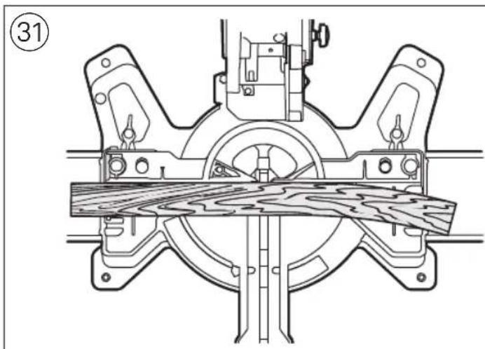
natural_image
Technical line drawing of a mechanical assembly with no visible text or symbols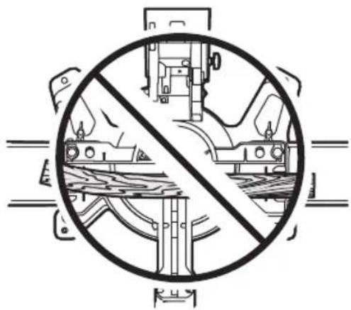
natural_image
Cross-sectional diagram of a mechanical device with no visible text or symbols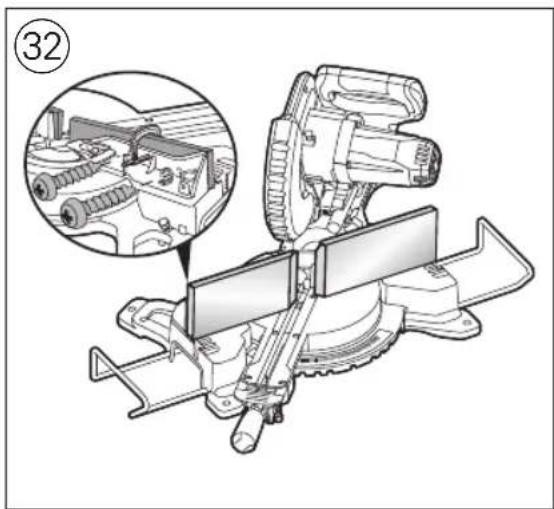
ACCESSORIES

WWW.SKIL.COM
GB
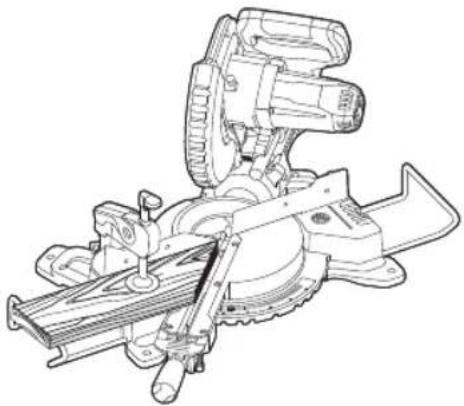
Cordless sliding mitre saw 3590 INTRODUCTION
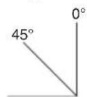
- This tool is intended as a stationary machine for lengthways and crossways cutting of wood with straight cuts as well as angle cuts (horizontal mitre angles of -47^ to +47^ as well as vertical bevel angles of 0^ to 45^ are possible)
- Read and save this instruction manual ②
• This tool is not intended for professional use - Only use the tool when correctly and completely assembled (be aware that Skil cannot be hold responsible for tool damage and/or personal injuries resulting from the incorrect assembly of the tool)
TECHNICAL DATA①
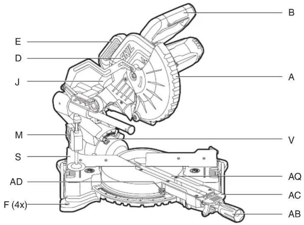
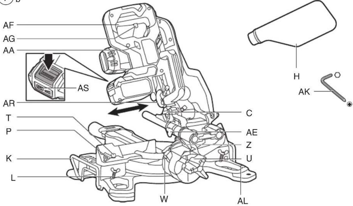
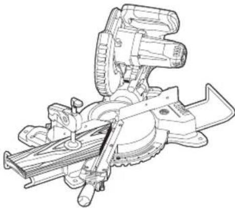
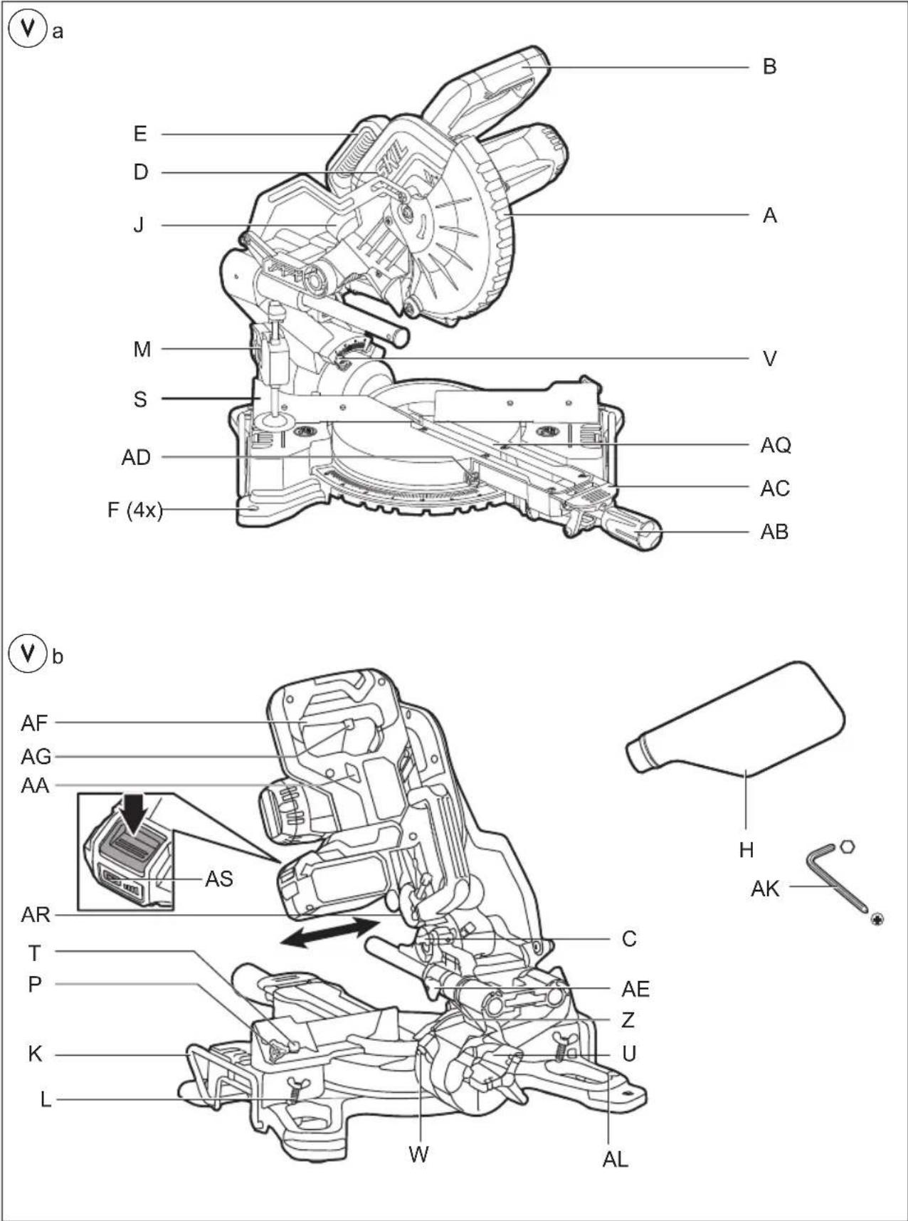
TOOL ELEMENTS ⑦
A Lower guard
B Switch handle
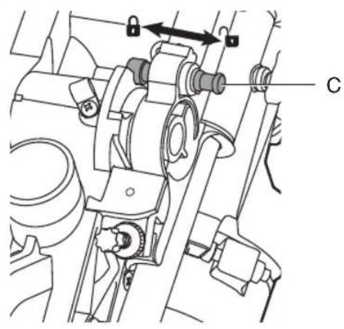
C Locking pin for transport
D Upper guard
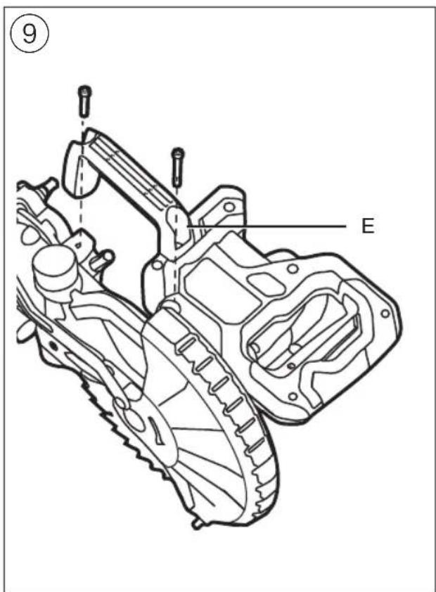
E Transport handle
F Mounting holes
G Support foot
H Dust bag
J Dust port
K Extension bars
L Knobs for locking extension bars
M Clamp for mounting workpiece
N Support hole
P Knob for fastening clamp
Q Knob for adjusting clamp
R Clamping lever
S Fence
T Hex screws for adjusting fence (2x)
U Locking knob (bevel angles)
V Bevel angle indicator
W Screw for adjusting bevel angle (right)
X Screw for adjusting bevel angle (left)
Y Laser adjustment screw
Z Laser light
AA On/off switch laser
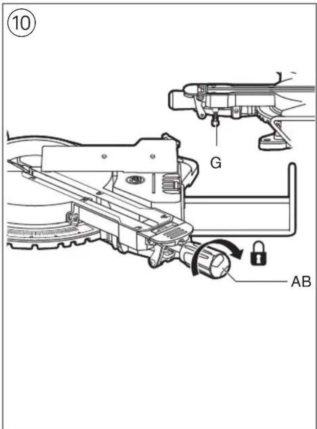
AB Locking handle (mitre angles)
AC Mitre detent release lever
AD Mitre angle indicator
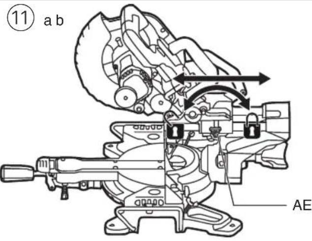
AE Locking knob for slide device
AF On/off switch
AG Safety lever
AH Cutting depth limiter
AI Depth stop
AJ Depth stop nut
AK Hex key
AL Storage for hex key
AM Spindle-lock button
AN Cover plate screw
AO Blade bolt
AP Flange
AQ Table insert
AR Dust deflector
AS Battery level indicator
SAFETY
GENERAL POWER TOOL SAFETY WARNINGS
WARNING Read all safety warnings, instructions, illustrations and specifications provided with this power tool. Failure to follow all instructions listed below may result in electric shock, fire and/or serious injury.
Save all warnings and instructions for future reference.
The term "power tool" in the warnings refers to your mains-operated (corded) power tool or battery-operated (cordless) power tool.
1) WORK AREA SAFETY
a) Keep work area clean and well lit. Cluttered or dark areas invite accidents.
b) Do not operate power tools in explosive atmospheres, such as in the presence of flammable liquids, gases or dust. Power tools create sparks which may ignite the dust or fumes.
c) Keep children and bystanders away while operating a power tool. Distractions can cause you to lose control.
2) ELECTRICAL SAFETY
a) Power tool plugs must match the outlet. Never modify the plug in any way. Do not use any adapter plugs with earthed (grounded) power tools. Unmodified plugs and matching outlets will reduce risk of electric shock.
b) Avoid body contact with earthed or grounded surfaces such as pipes, radiators, ranges and refrigerators. There is an increased risk of electric shock if your body is earthed or grounded.
c) Do not expose power tools to rain or wet conditions. Water entering a power tool will increase the risk of electric shock.
d) Do not abuse the cord. Never use the cord for carrying, pulling or unplugging the power tool. Keep cord away from heat, oil, sharp edges or moving parts. Damaged or entangled cords increase the risk of electric shock.
e) When operating a power tool outdoors, use an extension cord suitable for outdoor use. Use of a cord suitable for outdoor use reduces the risk of electric shock.
f) If operating a power tool in a damp location is unavoidable, use a residual current device (RCD) protected supply. Use of an RCD reduces the risk of electric shock.
3) PERSONAL SAFETY
a) Stay alert, watch what you are doing and use common sense when operating a power tool. Do not use a power tool while you are tired or under the influence of drugs, alcohol or medication. A moment of inattention while operating power tools may result in serious personal injury.
b) Use personal protective equipment. Always wear eye protection. Protective equipment such as a dust mask, non-skid safety shoes, hard hat, or hearing protection used for appropriate conditions will reduce personal injuries.
c) Prevent unintentional starting. Ensure the switch is in the off-position before connecting to power
source and/or battery pack, picking up or carrying the tool. Carrying power tools with your finger on the switch or energising power tools that have the switch on invites accidents.
d) Remove any adjusting key or wrench before turning the power tool on. A wrench or a key left attached to a rotating part of the power tool may result in personal injury.
e) Do not overreach. Keep proper footing and balance at all times. This enables better control of the power tool in unexpected situations.
f) Dress properly. Do not wear loose clothing or jewellery. Keep your hair and clothing away from moving parts. Loose clothes, jewellery or long hair can be caught in moving parts.
g) If devices are provided for the connection of dust extraction and collection facilities, ensure these are connected and properly used. Use of dust collection can reduce dust-related hazards.
h) Do not let familiarity gained from frequent use of tools allow you to become complacent and ignore tool safety principles. A careless action can cause severe injury within a fraction of a second.
4) POWER TOOL USE AND CARE
a) Do not force the power tool. Use the correct power tool for your application. The correct power tool will do the job better and safer at the rate for which it was designed.
b) Do not use the power tool if the switch does not turn it on and off. Any power tool that cannot be controlled with the switch is dangerous and must be repaired.
c) Disconnect the plug from the power source and/or remove the battery pack, if detachable, from the power tool before making any adjustments, changing accessories, or storing power tools. Such preventive safety measures reduce the risk of starting the power tool accidentally.
d) Store idle power tools out of the reach of children and do not allow persons unfamiliar with the power tool or these instructions to operate the power tool. Power tools are dangerous in the hands of untrained users.
e) Maintain power tools and accessories. Check for misalignment or binding of moving parts, breakage of parts and any other condition that may affect the power tool's operation. If damaged, have the power tool repaired before use. Many accidents are caused by poorly maintained power tools.
f) Keep cutting tools sharp and clean. Properly maintained cutting tools with sharp cutting edges are less likely to bind and are easier to control.
g) Use the power tool, accessories and tool bits etc., in accordance with these instructions, taking into account the working conditions and the work to be performed. Use of the power tool for operations different from those intended could result in a hazardous situation.
h) Keep handles and grasping surfaces dry, clean and free from oil and grease. Slippery handles and grasping surfaces do not allow for safe handling and control of the tool in unexpected situations.
5) BATTERY TOOL USE AND CARE
a) Recharge only with the charger specified by the manufacturer. A charger that is suitable for one type
of battery pack may create a risk of fire when used with another battery pack.
b) Use power tools only with specifically designated battery packs. Use of any other battery packs may create a risk of injury and fire.
c) When battery pack is not in use, keep it away from other metal objects, like paper clips, coins, keys, nails, screws or other small metal objects, that can make a connection from one terminal to another. Shorting the battery terminals together may cause burns or a fire.
d) Under abusive conditions, liquid may be ejected from the battery; avoid contact. If contact accidentally occurs, flush with water. If liquid contacts eyes, additionally seek medical help. Liquid ejected from the battery may cause irritation or burns.
e) Do not use a battery pack or tool that is damaged or modified. Damaged or modified batteries may exhibit unpredictable behavior resulting in fire, explosion or risk of injury.
f) Do not expose a battery pack or tool to fire or excessive temperature. Exposure to fire or temperature above 130 °C may cause explosion.
g) Follow all charging instructions and do not charge the battery pack or tool outside the temperature range specified in the instructions. Charging improperly or at temperatures outside the specified range may damage the battery and increase the risk of fire.
6) SERVICE
a) Have your power tool serviced by a qualified repair person using only identical replacement parts. This will ensure that the safety of the power tool is maintained.
b) Never service damaged battery packs. Service of battery packs should only be performed by the manufacturer or authorized service providers.
SAFETY INSTRUCTIONS FOR MITRE SAWS
- Mitre saws are intended to cut wood or wood-like products, they cannot be used with abrasive cut-off wheels for cutting ferrous materials such as bars, rods, studs, etc. Abrasive dust causes moving parts such as lower guard to jam. Sparks from abrasive cutting will burn the lower guard, the kerf insert and other plastic parts.
- Use clamps to support workpiece whenever possible. If supporting the workpiece by hand, you must always keep hand at least 100 mm from either side of the saw blade. Do not use this saw to cut pieces that are too small to be securely clamped or held by hand. If your hand is placed too close to the saw blade, there is an increased risk of injury from blade contact.
- The workpiece must be stationary and clamped or held against both the fence and the table. Do not feed the workpiece into the blade or cut “freehand” in any way Unrestrained or moving workpieces could be thrown at high speeds, causing injury.
- Push the saw through the workpiece. Do not pull the saw through the workpiece. To make a cut, raise the saw head and pull it out over the workpiece without cutting, start the motor, press the saw head down and push the saw through the workpiece Cutting on the pull stroke is likely to cause the saw blade to climb
on top of the workpiece and violently throw the blade assembly towards the operator.
- Never cross your hand over the intended line of cutting either in front or behind the saw blade Supporting the workpiece “cross handed” i.e. holding the workpiece to the right of the saw blade with your left hand or vice versa is very dangerous.
- Do not reach behind the fence with either hand closer than 100 mm from either side of the saw blade, to remove wood scraps, or for any other reason while the blade is spinning The proximity of the spinning saw blade to your hand may not be obvious and you may be seriously injured.
- Inspect your workpiece before cutting If the workpiece is bowed or warped, clamp it with the outside bowed face toward the fence. Always make certain that there is no gap between the workpiece, fence and table along the line of the cut Bent or warped workpieces can twist or shift and may cause binding on the spinning saw blade while cutting. There should be no nails or foreign objects in the workpiece.
- Do not use the saw until the table is clear of all tools, wood scraps, etc, except for the workpiece Small debris or loose pieces of wood or other objects that contact the revolving blade can be thrown with high speed.
- Cut only one workpiece at a time Stacked multiple workpieces cannot be adequately clamped or braced and may bind on the blade or shift during cutting.
- Ensure the mitre saw is mounted or placed on a level, firm work surface before use. A level and firm work surface reduces the risk of the mitre saw becoming unstable.
- Plan your work! Every time you change the bevel or mitre angle setting, make sure the adjustable fence is set correctly to support the workpiece and will not interfere with blade or the guarding system. Without turning the tool "ON" and with no workpiece on the table, move the saw blade through a complete simulated cut to assure there will be no interference or danger of cutting the fence.
- Provide adequate support such as table extensions, saw horses, etc. for a workpiece that is wider or longer than the table top. Workpieces longer or wider than the mitre saw table can tip if not securely supported. If the cut-off piece or workpiece tips, it can lift the lower guard or be thrown by the spinning blade.
- Do not use another person as a substitute for a table extension or as additional support Unstable support for the workpiece can cause the blade to bind or the workpiece to shift during the cutting operation pulling you and the helper into the spinning blade.
- The cut-off piece must not be jammed or pressed by any means against the spinning saw blade If confined, i.e. using length stops, the cut-off piece could get wedged against the blade and thrown violently.
- Always use a clamp or a fixture designed to properly support round material such as rods or tubing. Rods have a tendency to roll while being cut, causing the blade to "bite" and pull the work with your hand into the blade.
- Let the blade reach full speed before contacting the workpiece This will reduce the risk of the workpiece being thrown.
- If the workpiece or blade becomes jammed, turn the mitre saw off. Wait for all moving parts to stop and disconnect the plug from the power source
and/or remove the battery pack. Then work to free the jammed material Continued sawing with a jammed workpiece could cause loss of control or damage to the mitre saw.
- After finishing the cut, release the switch, hold the saw head down and wait for the blade to stop before removing the cut-off piece Reaching with your hand near the coasting blade is dangerous.
- Hold the handle firmly when making an incomplete cut or when releasing the switch before the saw head is completely in the down position The braking action of the saw may cause the saw head to be suddenly pulled downward, causing a risk of injury.
ADDITIONAL SAFETY INSTRUCTIONS
GENERAL
- Only use the tool for cutting wood
- Do not stand on tool or its stand Serious injury may occur if the tool is tipped or if the cutting tool is accidentally contacted. Do not store materials on or near the tool such that it is necessary to stand on the tool or its stand to reach them.
• Always remove battery pack from the tool before making any adjustment or changing any accessory - Always remove battery pack from the tool before transporting the mitre saw. Remove battery pack, lower head assembly and lock into position, use the carry handle and one of the hand indentations in the saw base.
- Do not leave tool until it comes to a complete stop
- When cutting irregularly shaped workpieces, plan your work so it will not slip and pinch the blade and be torn from your hand
- This tool should not be used by people under the age of 16 years
• This tool is not suitable for wet cutting
BEFORE USE
- Wear protective glasses, hearing protection, and protective gloves
- Dust from material such as paint containing lead, some wood species, minerals and metal may be harmful (contact with or inhalation of the dust may cause allergic reactions and/or respiratory diseases to the operator or bystanders); wear a dust mask and work with a dust extraction device when connectable
- Certain kinds of dust are classified as carcinogenic (such as oak and beech dust) especially in conjunction with additives for wood conditioning; wear a dust mask and work with a dust extraction device when connectable
- Follow the dust-related national requirements for the materials you want to work with
- Do not work materials containing asbestos (asbestos is considered carcinogenic)
- Never use the tool without the original protection guard system
- Check the protective guard for proper closing before each use
- Do not operate the saw if the protective guard does not move freely and close instantly
- Never clamp or tie the protective guard into the open position
- Never use the tool without the table insert; replace a defective or worn table insert
- Remove all obstacles on top of as well as underneath the cutting path before you start cutting
- Avoid damage that can be caused by screws, nails and other elements in your workpiece; remove them before you start working
ACCESSORIES
- Never use grinding/cutting discs with this tool
- SKIL can assure flawless functioning of the tool only when the correct accessories are used which can be obtained from your SKIL dealer
- For mounting/using non-SKIL accessories observe the instructions of the manufacturer concerned
- Use only saw blades that correspond with the characteristic data given in these operation instructions and that are tested and marked in accordance with EN 847-1
- Use only accessories with an allowable speed matching at least the highest no-load speed of the tool
- Never use saw blades made of high speed steel (HSS)
- Do not use a saw blade which is cracked, deformed or dull
- Only use saw blades with a hole diameter which fits the tool spindle without play; never use reducors or adaptors to fit large-hole saw blades
- Protect accessories from impact, shock and grease
DURING USE
- Do not force the tool (apply light and continuous pressure in order to avoid overheating the blade tips and, in case of cutting plastics, melting the plastic material)
- Keep fingers, hands and arms away from the rotating saw blade
- If the saw blade becomes blocked, switch off the tool immediately and remove the battery pack; only then remove the wedged workpiece
- In case of jamming or electrical or mechanical malfunction, immediately switch off the tool and remove the battery pack
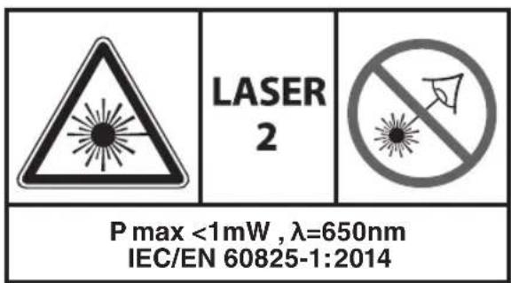
LASER RADIATION
- Do not direct the laser beam at persons or animals and do not stare into the direct or reflected laser beam yourself, not even from a distance (you could blind somebody, cause accidents or damage your eyes)
- If laser radiation strikes your eye, you must deliberately close your eyes and immediately turn your head away from the beam
- Do not make any modifications to the laser equipment
- Do not look into the laser beam (laser radiation)
- Do not use any magnifying optical tools (such as magnifying glasses, telescopes, or binoculars) to view the laser beam
- Do not operate the tool in the presence of flammable liquids, gases or dust
- Do not operate the tool with children around
- Do not replace the installed laser with another laser type
AFTER USE
- After switching off the tool, never stop the rotation of the accessory by a lateral force applied against it
- Only remove cut-offs or other parts of the workpiece from the cutting area when all moving parts have come to a complete standstill
- the saw blade becomes very hot during use; do not touch it before it has cooled down
- Store the tool indoors in a dry and locked-up place, out of reach of children
BATTERIES
- The battery supplied is partially charged (to ensure full capacity of the battery, completely charge the battery in the battery charger before using your power tool for the
first time)
- Only use the following batteries and chargers with this tool
-SKIL battery: BR1*31****
-SKIL charger: CR1*31****
- Do not use the battery when damaged; it should be replaced
- Do not disassemble the battery
- Do not expose tool/battery to rain
- Permitted ambient temperature (tool/charger/battery):
- when charging 4...40°C
- during operation -20...+50°C
- during storage -20...+50°C
EXPLANATION OF SYMBOLS ON TOOL
② Read the instruction manual before use
③ Wear protective glasses and hearing protection
④ Danger area! No hands zone. Keep hands, fingers or arms away from this area.
⑤ Do not dispose of electric tools and batteries together with household waste material
⑥ Laser radiation / Do not stare into beam / Class 2 laser product
USE
- Assembly
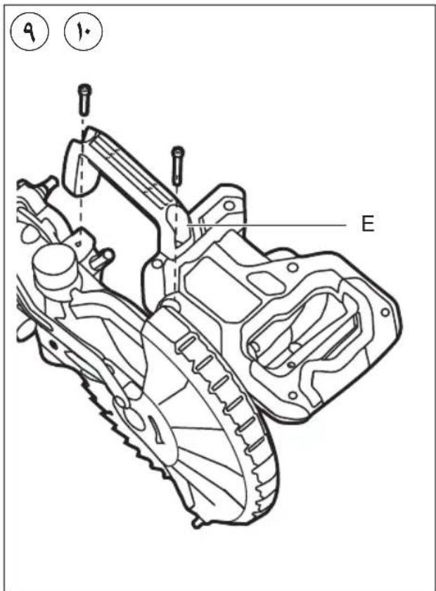
-assemble the transport handle with 2 bolts using hex key AK⑨
-assemble the mitre lock knob AB into the front of the table ⑩
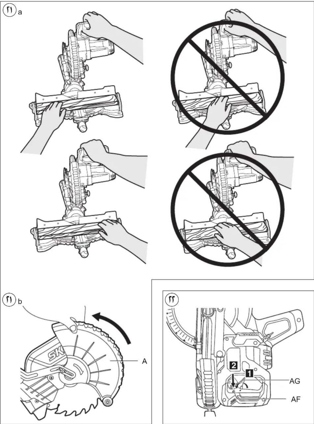
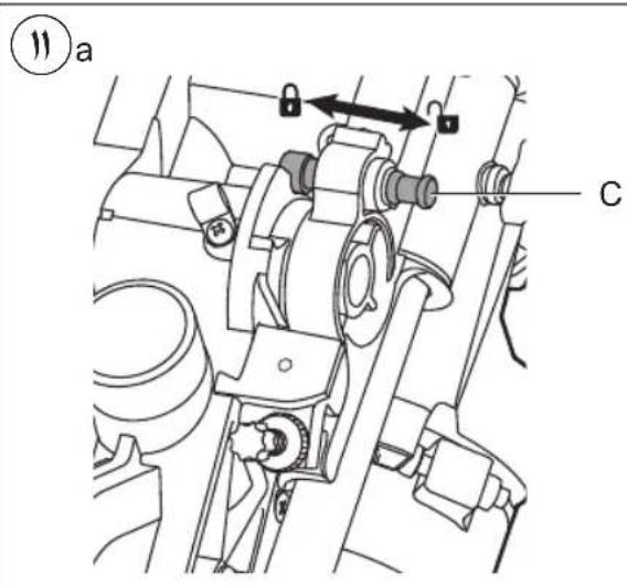
• Transport/working position
For releasing the tool (working position)
-press handle B downward with one hand while pulling out locking pin C with the other hand ⑪a
-guide the head assembly slowly upward
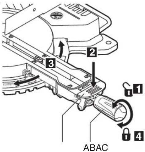
-for sawing with slide movement loosen locking knob AE ⑪b
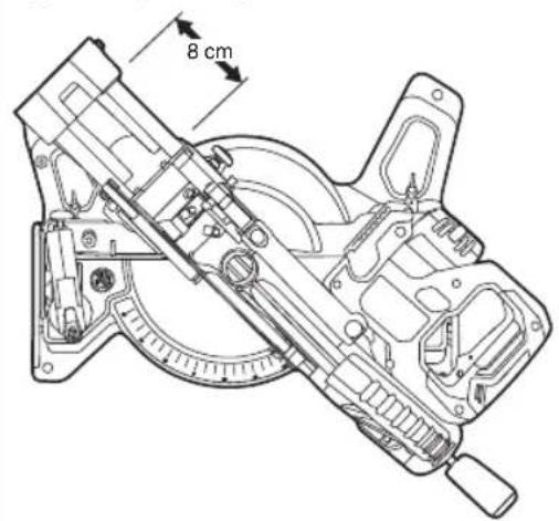
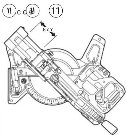
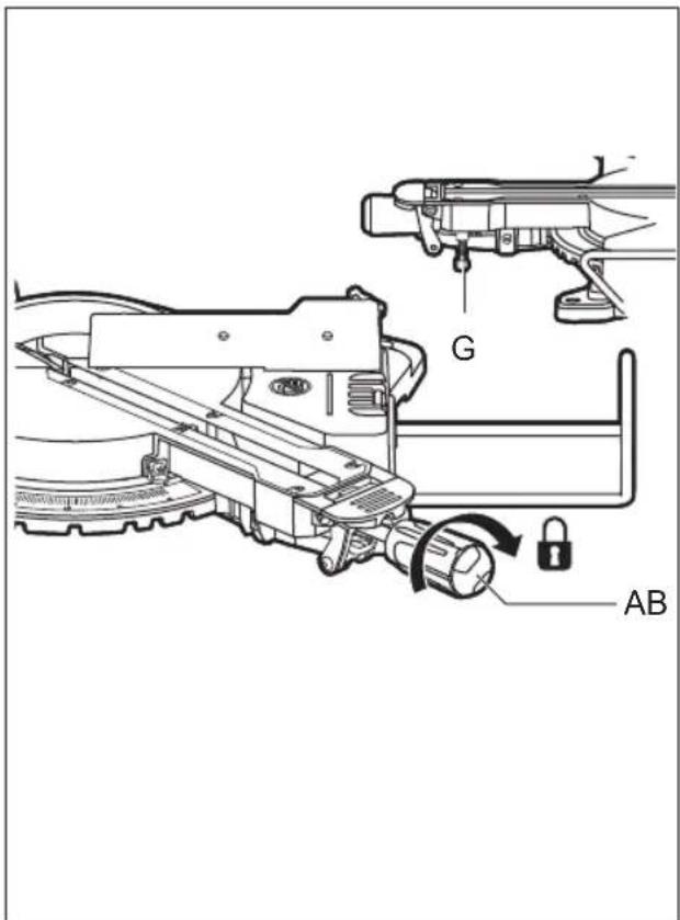
For securing the tool (transport position)
-slide the head assembly about 8 cm from the back and tighten locking knob AE ⑪c
-set the bevel angle to 0° (see Setting bevel angle)
-set the mitre angle to 45^ left or right (see Setting mitre angle)
-press handle B downward with one hand while pushing locking pin C with the other hand
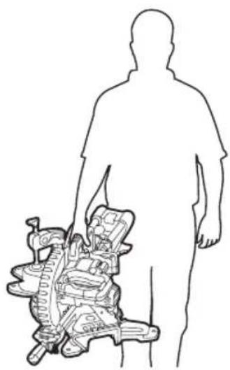
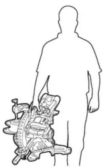
-use transport handle E for carrying the tool ⑪d
-alternatively, use the side handles for carrying the tool ⑪e
! never lift the tool by holding the main handle
- Mounting tool on working surface ⑫
! for safe handling always mount tool on a flat and stable working surface (e.g. workbench)
-use 4 mounting holes F for attaching the tool with suitable screws to the working surface
-you may also clamp the tool to the working surface with commercially available screw clamps
-for stabilizing the tool the height of support foot G can be adjusted
-alternatively, the tool can be mounted onto a mitre saw stand
! read all the warnings and instructions included with the saw stand
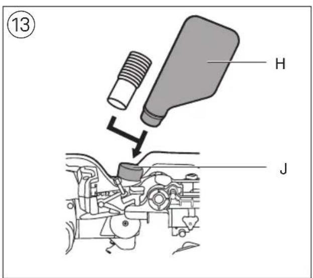
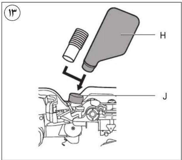
• Dust/chip extraction ⑬
-mount dustbag H/vacuum cleaner as illustrated
-empty dust bag regularly for optimal dust pick-up performance
! never let the vacuum cleaner hose interfere with the lower guard or the cutting operation
- Charging battery
! read the safety warnings and instructions provided with the charger
- Removing/installing the battery ⑦b
-recommended to use the saw with at least 4.0Ah battery pack
- Battery level indicator ⑧
-press the battery level indicator button AS to show the current battery level ⑧a
! if the lowest level of the battery indicator starts flashing after pressing button AS ⑧b, the battery is empty
! if 2 levels of the battery indicator start flashing after pressing button AS ⑧c, the battery is not within the allowable operating temperature range
- Battery protection
The tool is suddenly being switched off or prevented from being switched on, when
- the load is too high --> remove load and restart -the battery temperature is not within the allowable operating temperature range of -20 to +50°C --> 2 levels of the battery level indicator start flashing when pressing button AS ⑧d; wait until battery has returned within the allowable operating temperature range -the battery is nearly empty (to protect against deep discharge) --> a low battery level or flashing low battery level ⑧b is shown by the battery level indicator when pressing button AS; charge battery
! do not continue to press the on/off switch after the tool is switched off automatically; battery may be damaged
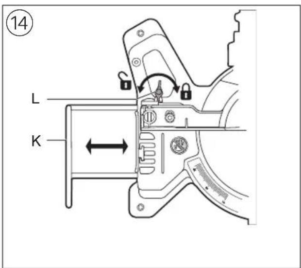
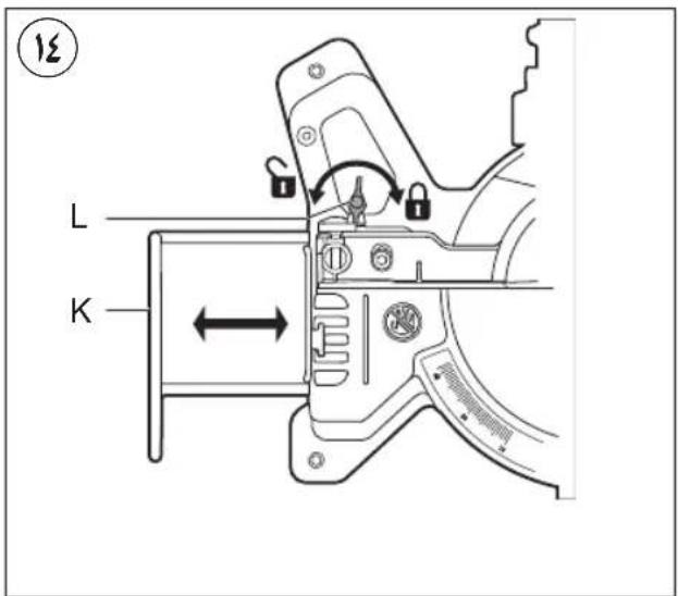
- Saw table extension ⑭
-use knobs L to fasten extension bars K (on either side of the tool)
-the length of extension bars K is steplessly adjustable from minimum to maximum
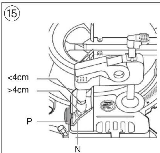
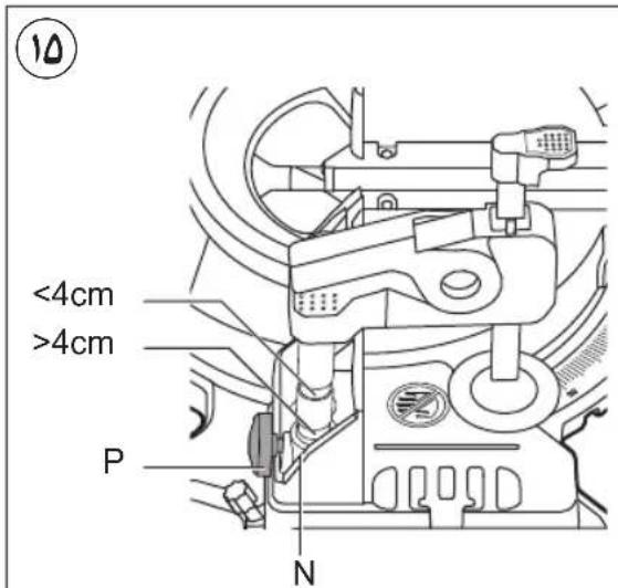
- Clamping the workpiece ⑮
! for optimum working safety always firmly clamp the workpiece with the adjustable clamp supplied
-do not work with workpieces that are too small to clamp
- for maximal workpiece dimensions use table ⑯ as reference
-fasten workpiece clamp into support hole N with knob P (on either side of the tool)
-use 1 of the 2 grooves; for workpiece thickness up to 4cm and workpiece thickness over 4cm
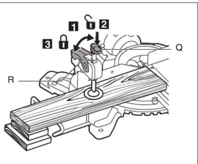
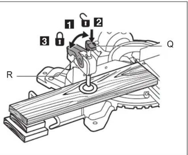
-press the workpiece firmly against fence S
-unlock lever R
-adapt clamp to the workpiece
-firmly clamp the workpiece by locking lever R
! for some mitre and bevel combinations, or depending on the size of the workpiece, it may be necessary to use commercially available screw clamps instead of the workpiece clamp
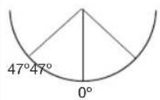
- Setting mitre angles ⑰
-loosen locking handle AB
-press down mitre detent release lever AC
-rotate the saw table to the left or right and set the desired mitre angle (from 0^ to 47^ ) by using indicator
AD
-release lever AC
- tighten locking handle AB (do not tighten the handle too firmly)
-for quick and precise setting of often used mitre angles (0°, 15°, 22.5°, 31.6°, 45°) the mitre detent lever clicks into place at the corresponding positions
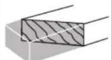
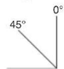
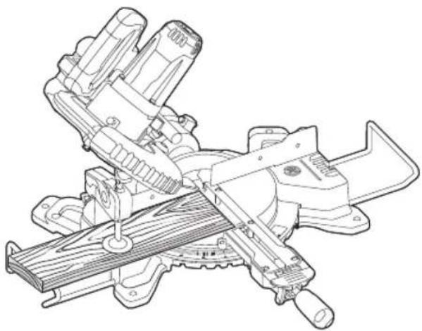
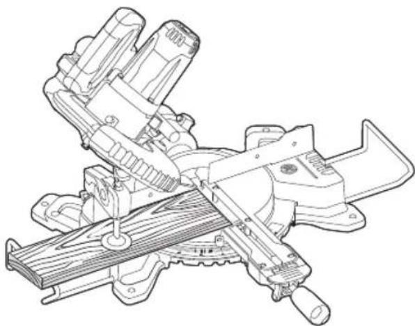
- Setting bevel angles ⑱
-loosen three-legged knob U 18b
-swing the saw head to the left until bevel angle indicator V points to the desired bevel angle
-hold the saw head in this position and tighten knob U
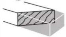
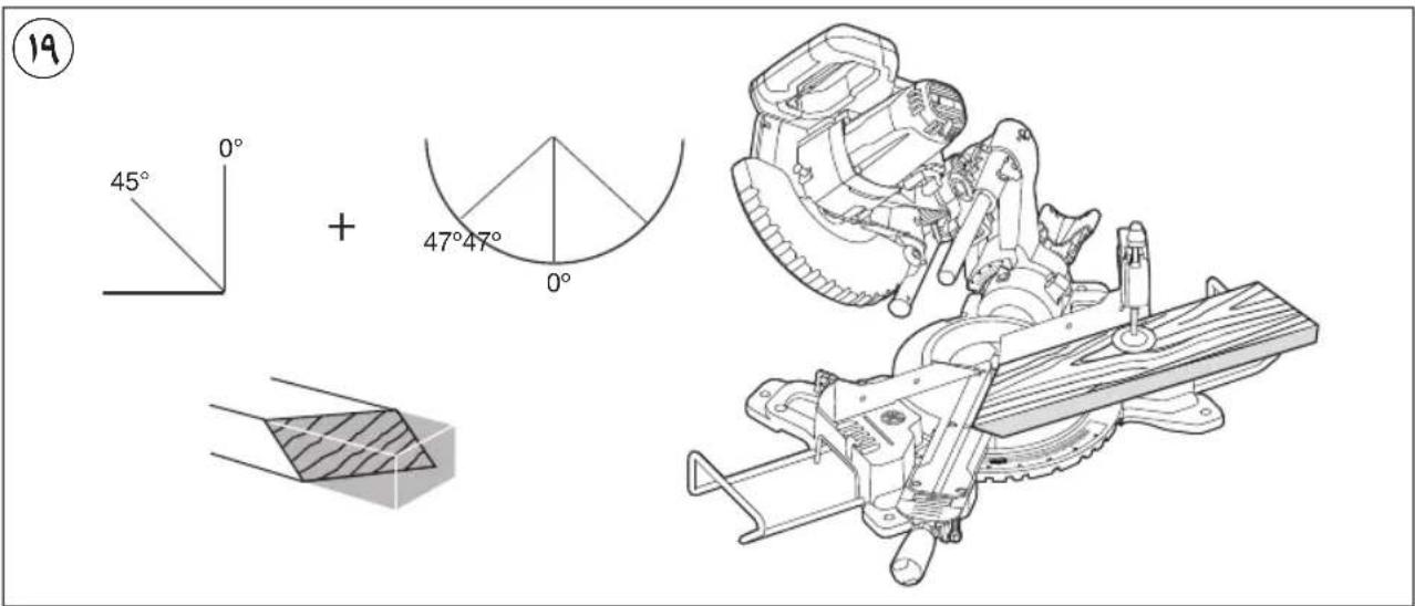
- Compound cuts ⑲
-compound cuts require both a mitre angle setting and a bevel angle setting
! do not operate the saw in certain of the mitre and bevel combinations which may result in interference between the sliding and stationary parts of the saw or between the sliding parts and the workpiece
! always test out first on a piece of scrap material
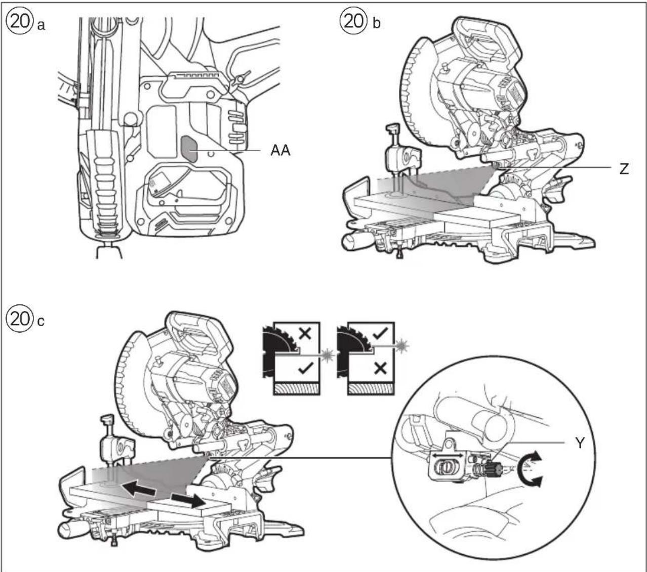
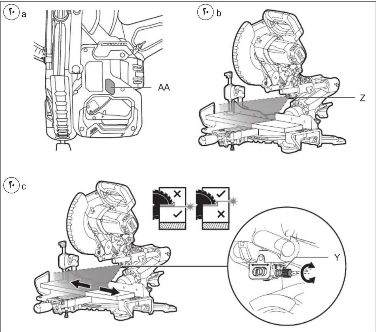
- Laser line ⑳
-for guiding tool along desired line of cut marked on the workpiece
-switch on/off laser line by pressing switch AA
-the laser is aligned to the left side of the cut
-the horizontal alignment of the laser can be easily adjusted with screw Y
! before starting a job, check the alignment of the laser line with the actual line of cut by making a trial cut on a piece of waste material
- Sawing without slide movement (small workpieces)
-loosen locking knob AE in case it is tightened
-slide the saw head to the stop in the direction of fence S and retighten locking knob AE
! failure to lock the mechanism can cause the blade to suddenly climb up on the top of the workpiece and force itself toward you
-set tool into working position
! ensure that the workpiece is firmly clamped against the saw table and fence S
-switch on the tool by releasing the lock-off AG and pulling the main switch AF ^22
! do not cross your arms when operating the saw head ②a
-saw through the workpiece with uniform advancing
! the tool should run at full speed before the blade enters into the workpiece
-switch off the tool by releasing switch AF
-wait until the sawblade has come to a complete standstill before guiding the saw head slowly upward
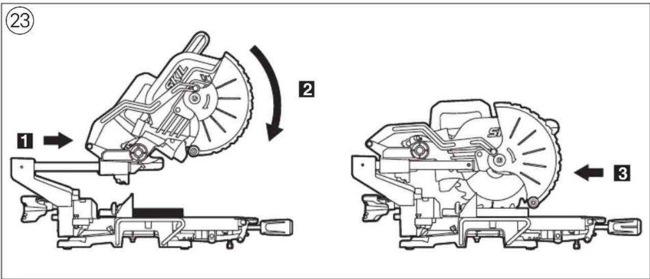
• Sawing with slide movement (wide workpieces)
! be aware that the method described below is the only safe one
-do not pull the saw through the workpiece
-loosen locking knob AE in case it is tightened
! ensure that the workpiece is firmly clamped against the saw table and fence S
-pull the saw head away from fence S far enough so that the saw blade is in front of the workpiece ②
-switch on the tool by pushing safety lever AG and pulling the main switch AF ^22
! do not cross your arms when operating the saw
head 21a
-push the saw head in the direction of fence S and saw through the workpiece with uniform advancing ②3
! the tool should run at full speed before the blade enters into the workpiece
! if the lower guard does not automatically open which can happen under certain conditions (e.g. a workpiece which is very close to the maximum capacity) you may have to open the guard by hand ⑳b
-switch off the tool by releasing switch AF -wait until the sawblade has come to a complete standstill before guiding the saw head slowly upward
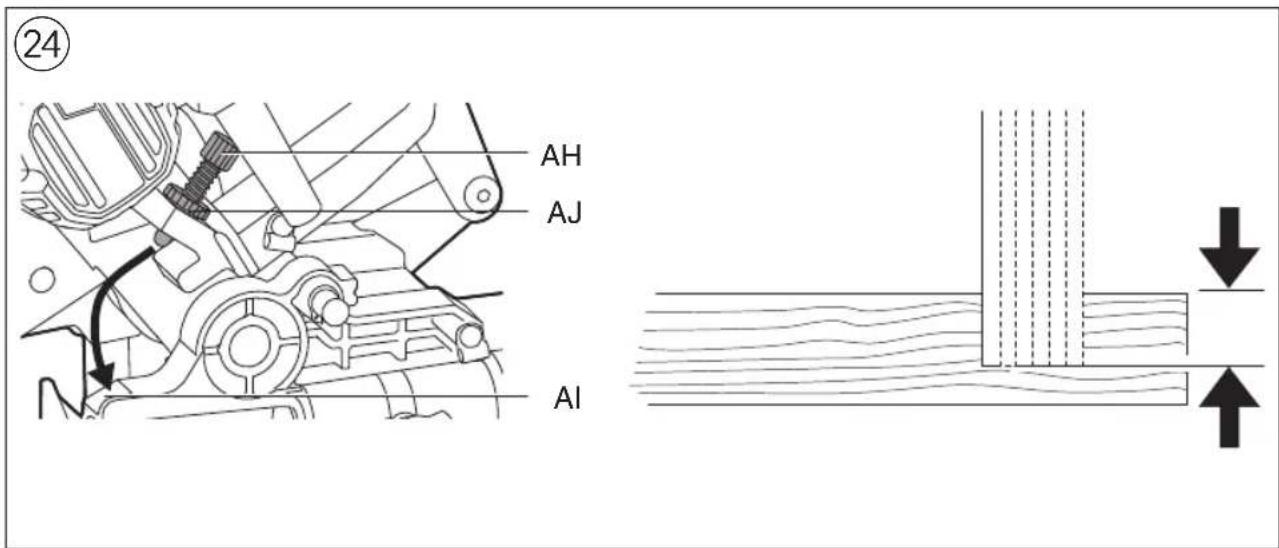
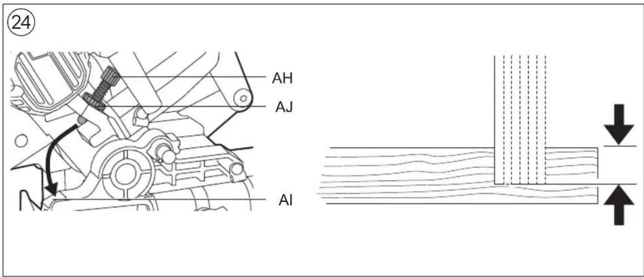
- Sawing grooves 24
-set the desired depth with depth stop AH and lock it in place by tightening nut AJ
-a wooden spacer shall be placed between the workpiece and the fence for a consistent depth over the full length of the groove
! ensure that the saw blade does not get jammed in the workpiece
! always test out first on a piece of scrap material
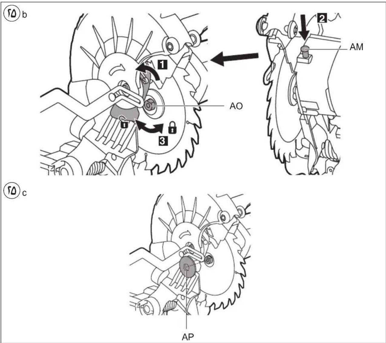
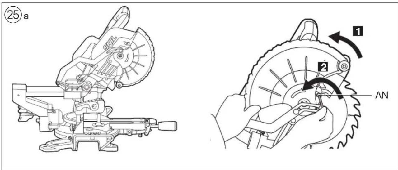
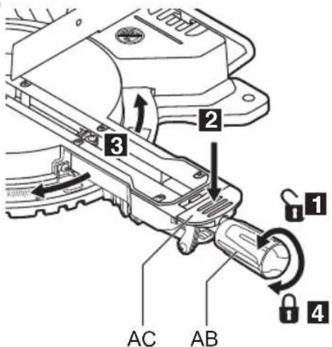
- Changing saw blade ②5
! remove the battery pack
-take hex key AK from storage AL
-hold protective guard A in open position
loosen cover plate screw AN (do not unscrew the screw completely) 25a
-rotate protective guard A completely backwards ^25 b
-push spindle-lock button AM and hold it while you remove blade bolt AO by turning hex key AK
CLOCKWISE (= in same direction as arrow printed on saw blade)
! push spindle-lock button AM only when tool is at a standstill
-release spindle-lock button AM
-remove flange AP and saw blade
! change saw blade with saw teeth and arrow printed on saw blade pointing in same direction as arrow on protective guard A
-mount flange AP 25c
-push spindle-lock button AM and hold it while you tighten blade bolt by turning hex key AK COUNTER CLOCKWISE 1/8 turn past finger tight (ensures slippage of saw blade when it encounters excessive resistance thus reducing motor overload and saw kickback)
-tighten cover plate screw AN
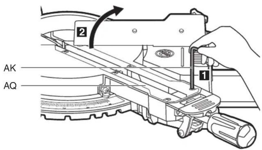
- Replacing table insert AQ ②6
Replace a defective or worn table insert as follows:
! remove the battery pack
-take hex key AK from storage AL
-remove all 6 screws as illustrated
-remove old table insert by first lifting it at the front and then pulling it out completely
-place new table insert
! firmly tighten all 6 screws
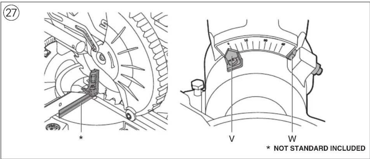
- Checking/adjusting of 90° blade alignment ⑳! remove the battery pack
-rotate the saw table to the 0° mitre position and lock in place
-swing the saw head to 0° bevel position
-lower the saw head and lock in place
-check for a 90° angle between blade and table with a square
-if necessary, adjust the 90° blade alignment as follows:
- loosen three-legged knob U
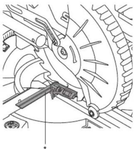
- adjust screw W with a blade wrench 10 (not standard included)
- re-check with square
- reset the bevel indicator V to 0°
- Checking/adjusting of 45° blade alignment ⑳ ! remove the battery pack
-rotate the saw table to the 0° mitre position and lock in place
-loosen three-legged knob U
-swing the saw head to the left
-check for a 45° angle between blade and table with a mitre square
-check that bevel indicator V is on the 45° mark
-if necessary, adjust the 45° blade alignment as follows:
-
adjust screw X with a blade wrench 10 (not standard included)
-
re-check with mitre square
- Checking/adjusting of 90° fence alignment ⑲ ! remove the battery pack
-rotate the saw table to the 0° mitre position and lock in place
-lower the saw head and lock in place
-check for a 90° angle between blade and fence S with a square (ensure the square contacts the saw blade body and not its teeth) ^29 a
-if necessary, adjust the 90° fence alignment as follows:
- loosen 2 hex screws T ^29b
- adjust fence until blade and fence have full contact with the square
- tighten 2 hex screws T
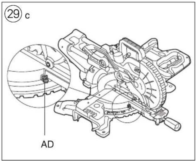
- reset the mitre indicator to 0°⑲c
APPLICATION ADVICE
- Special workpieces
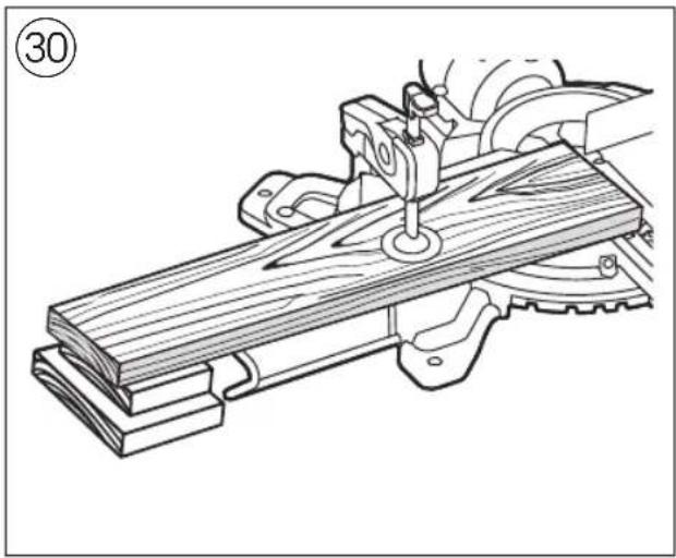
-always support the free ends of a long workpiece ③0
-ensure that curved or round workpieces are especially secured against slipping ③1
-at the cutting line no gap may exist between the workpiece and the fence or saw table
-if necessary, fabricate an auxiliary fence; the holes in the fence shall be used to secure the auxiliary fence ③2
! the auxiliary fence can only be used at 0° bevel
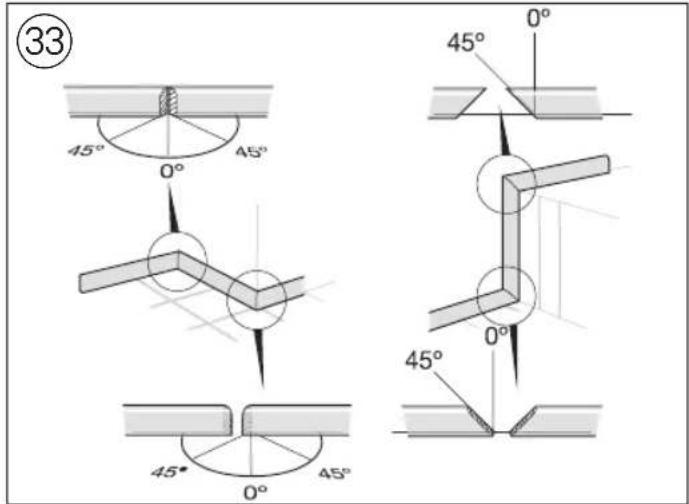
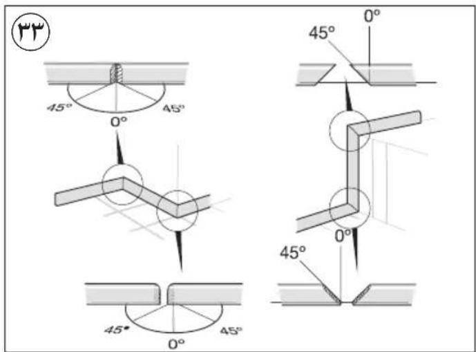
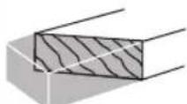
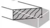
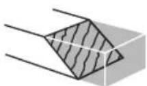
- For working with floor mouldings illustration ③ can be used as reference
• Always face the good side of the workpiece down to ensure minimum splintering - Only use sharp saw blades of the correct type -quality of cut improves by the number of teeth
-carbide tipped blades stay sharp up to 30 times longer than ordinary blades
MAINTENANCE / SERVICE
• Always keep tool clean (especially the ventilation slots at the back-end of the motor housing)
- Develop a regular check to make sure the lower guard is working properly. Clean the lower guard of any sawdust build up with a damp cloth.
! remove the battery pack before cleaning
-lift the lower guard to the fully open position and release it; if it does not immediately and fully close it should be checked by an after-sales service centre for SKIL power tools
- Clean saw blade immediately after use (especially from resin and glue)
! the saw blade becomes very hot during use; do not touch it before it has cooled down
- Clean the laser light AC with a soft brush after each use to keep a good visibility of the laser line (make sure that you do not change the setting of the laser)
- If the tool should fail despite the care taken in manufacturing and testing procedures, repair should be carried out by an after-sales service centre for SKIL power tools
- send the tool undismantled together with proof of purchase to your dealer or the nearest SKIL service station (addresses as well as the service diagram of the tool are listed on www.skil.com)
- Be aware that damage due to overload or improper handling of the tool will be excluded from the warranty (for the SKIL warranty conditions see www.skil.com or ask your dealer)
ENVIRONMENT
Only for EU countries
- Do not dispose of electric tools, accessories and packaging together with household waste material
- in observance of European Directive 2012/19/EC on waste of electric and electronic equipment and its implementation in accordance with national law, electric tools that have reached the end of their life must be collected separately and returned to an environmentally compatible recycling facility
- symbol ⑤ will remind you of this when the need for disposing occurs
! prior to disposal protect battery terminals with heavy tape to prevent short-circuit
Only for UK
- Do not dispose of electric tools, accessories and packaging together with household waste material
- in observance of on Waste Electric and Electronic Equipment Regulations 2013 (SI 2013/3113), electric tools that have reached the end of their life must be collected separately and returned to an environmentally compatible recycling facility
- symbol ⑤ will remind you of this when the need for disposing occurs
! prior to disposal protect battery terminals with heavy tape to prevent short-circuit
NOISE
- Measured in accordance with EN 62841 the sound pressure level of this tool is 90.0 dB(A) and the sound power level 100 dB(A) (uncertainty K = 3 dB)
- The noise emission level has been measured in accordance with a standardised test given in EN 62841; it may be used to compare one tool with another and as a preliminary assessment of exposure to noise when using the tool for the applications mentioned
-the noise emissions during actual use of the power tool can differ from the declared values depending on the ways in which the tool is used especially what kind of
workpiece is processed
- operator needs to identify safety measures to protect the operator that are based on an estimation of exposure in the actual conditions of use (taking account of all parts of the operating cycle such as the times when the tool is switched off and when it is running idle in addition to the trigger time)
F
CONSEILS D'APPLICATION
- Pièces spéciales
1) SIKKERHET I ARBEIDSOMRÅDET
Save all warnings and instructions for future reference.
DODATNE SIGURNOSNE UPUTE
OPĆENITO
- Alat upotrebljavajte samo za rezanje drveta
- Nemojte stajati na alatu ili njegovom postolju Može nastati ozbiljna ozljeda ako se alat prevrne ili ako slučajno dodirnete alat za rezanje. Ne čuvajte materijale na alatu ili blizu njega tako da je potrebno stajati na alatu ili njegovom postolju kako biste došli do njih.
- Izvadite baterijski modul iz alata prije bilo kakvog podešavanja ili promjene priobra
- Izvadite baterijski modul iz alata prije prijenosa nagibne pile. Uklonite baterijski modul, spustite sklop glave i fiksirajte ga na njegovom mjestu, koristite ručku za nošenje i jednu od ručnih udubljenja u postolja pile.
- Ne ostavljajte alat dok se potpuno ne zaustavi
- Prilikom rezanja izrađevine nepravilnog oblika, planirajte svoj rad tako da on ne sklizne i ne stisne pilu i ne istrgne se iz ruke
- Ovaj alat ne smiju upotrebljavati osobe mlađe od 16 godina.
DODATNA BEZBEDNOSNA UPUTSTVA
OPŠTA
- Koristite alat samo za sečenje drveta
- Nemojte stajati na alatu ili njegovom postolju Može doći do ozbiljnih povreda ako se alat prevrne ili ako se alat za rezanje slučajno dodirne. Ne skladištite materijale na ili u blizini alata tako da je potrebno stajati na alatu ili njegovom postolju da biste ih dohvatili.
- Uvek izvadite bateriju iz alata pre nego što izvršite bilo kakvo podešavanje ili promenu bilo kog pribora
- Uvek uklonite bateriju iz alata pre transporta ugaone testere. Uklonite bateriju, spustite dole sklop glave i zaključajte u tom položaju, koristite ručicu za nošenje i jedno od udubljenja za ruku u bazi testere.
- Ne napuštajte alat dok ne dođe do potpunog zaustavljanja
- Kada sečete obratke nepravilnog oblika, planirajte svoj rad tako da ne bi skliznuli i uhvatili sečivo i bili istrgnuti iz vaše ruke
- Ovaj alat ne treba da koriste osobe ispod 16 godina
- Ovaj alat nije pogodan za mokro sečenje
PRE UPOTREBE
- Nosite zaštitne naočare, zaštitu sluha i zaštitne rukavice
- Prašina od materijala poput farbe koja sadrži olovo, nekih vrsta drveta, minerala i metala može biti škodljiva (dodir sa tom prašinom ili njeno udisanje mogu izazvati alergijske reakcije i/ili respiratorne bolesti kod rukovaoca ili posmatrača); nosite masku za prašinu i radite sa uređajem za uklanjanje prašine kad ga je moguće spojiti
- Određene vrste prašine se klasifikuju kao karcinogene (poput prašine od hrasta i bukve), naročito u kombinaciji sa aditivima za kondicioniranje drveta; nosite masku za prašinu i radite sa uređajem za uklanjanje prašine kad ga je moguće spojiti
- Pratite nacionalne zahteve vezane za prašinu za materijale sa kojima želite da radite
- Ne radite sa materijalima koji sadrže azbest (azbest se smatra karcinogenim)
- Nikad ne koristite alat bez originalnog zaštitnog sistema
- Pre svake upotrebe proverite da li je štitnik pravilno zatvoren.
- Nemojte upotrebljavati testeru ako se štitnik ne kreće slobodno i ako se ne zatvara odmah.
- Nikad nemojte da fiksirate ili vezujete donji štitnik u otvoreni položaj.
- Nikada ne koristite alat bez umetka postolja; zamenite neispravan ili istrošeni umetak postolja
- Uklonite sve prepreke na iznad i ispod putanje sečenja pre nego što počnete da sečete
- Izbegavajte oštećenja koja mogu izazvati šrafovi, ekseri i drugih elementi u obratku; uklonite ih pre nego što započnete rad
PRIBÓR
- Nikada ne koristite brusne/rezne diskove sa ovim alatom
- SKIL može osigurati besprekorno funkcionisanje alata samo kada se koristi odgovarajući pribor koji možete nabaviti od vašeg SKIL prodavca
- Za montažu/korišćenje pribora koji nije SKIL, pridržavajte se uputstava dotičnog proizvođača
- Koristite samo sečiva koja odgovaraju podacima o karakteristikama datim u ovom uputstvu za rukovanje i koja su testirana i obeležena u skladu sa EN 847-1
- Koristite samo pribor čija dozvoljena brzina odgovara barem najvećoj brzini alata u praznom hodu
-
Nikad ne koristite listove testere napravljene od čelika velike brzine (HSS)
-
Nemojte koristiti list testere koji je napukao, deformisan ili tup
- Koristite samo listove testere prečnika rupe koji odgovaraju vretenu alata bez slobodnog kretanja; nikada ne koristite reduktore ili adaptere za postavljanje listova testere sa velikim rupama
- Zaštitite dodatnu opremu od udaraca, potresa i masnoće TOKOM UPOTREBE
- Ne forsirajte alat (primenite lak i kontinuiran pritisak da biste izbegli pregrevanje vrhova sečiva i, u slučaju sečenja plastike, topljenje plastičnog materijala)
- Držite prste, šake i ruke dalje od rotirajućeg lista testere
- Ako se list testere blokira, odmah isključite alat i uklonite bateriju; tek onda uklonite zaglavljeni obradak
- U slučaju da dođe do zaglavljivanja ili električnog ili mehaničkog kvara, odmah isključite alat i izvadite bateriju
LASERSKO ZRAČENJE
- Ne usmeravajte laserski zrak na ljude ili životinje i ne gledajte u direktni ili reflektovani laserski zrak, čak ni iz daljine (mogli biste nekoga zaslepiti, izazvati nesreće ili oštetiti oči)
- Ako vam lasersko zračenje pogodi oko, morate namerno zatvoriti oči i odmah okrenuti glavu podalje od zraka
- Ne pravite nikakve modifikacije laserske opreme
- Ne gledajte u laserski zrak (lasersko zračenje)
- Ne koristite nikakve optičke alate koji uvećavaju (kao što je lupa, teleskop ili dvogled) da biste videli laserski zrak
- Ne koristite alat u prisustvu zapaljivih tečnosti, gasova ili prašine
- Ne koristite alat u blizini dece
- Ne zamenjujte instalirani laser drugim tipom lasera
NAKON UPOTREBE
- Nakon isključivanja alata, nikada ne zaustavljajte rotaciju dodatne opreme primenom bočne sile na nju
- Uklonite odsečke ili druge delove obratka sa područja sečenja tek kada su se svi pokretni delovi potpuno zaustavili
- list testere postaje veoma vruć tokom upotrebe; ne dodirujte ga pre nego što se ohladi
- Skladištite alat u zatvorenom prostoru, na suvom i zaključanom mestu, van domašaja dece
BATERIJE
- Baterija se isporučuje delimično napunjena (da biste osigurali pun kapacitet baterije, bateriju napunite do kraja u punjaču baterije pre prvog korišćenja električnog alata)
- Isključivo koristite sledeće baterije i punjače sa ovim alatom
-SKIL baterija: BR1*31****
-SKIL punjač: CR1*31****
NURGASAAGIDE OHUTUSJUHISED
TECHNINIAI DUOMENYS ①
IRANKIO DALYS⑦
LAMarket EXAMOUNTING
natural_image
Technical line drawing of a mechanical assembly with wooden base and gear mechanism (no text or symbols)
natural_image
Technical line drawing of a mechanical assembly with no visible text or symbols
natural_image
Cross-sectional diagram of a mechanical device with no visible text or symbols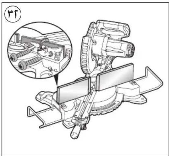
ACCESSORIES

WWW.SKIL.COM
natural_image
Technical line drawing of a mechanical assembly with no visible text or symbols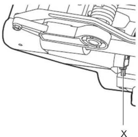
natural_image
Technical line drawing of a mechanical assembly with no visible text or symbolsnatural_image
Mechanical assembly diagram showing gear and pulley components (no text or labels)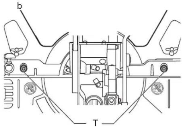
* NOT STANDARD INCLUDED
7


17
| | Max A x Max B | |
| 0° 0° | | 70 x 220 mm | |
| 45° 0° | 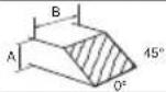 | 40 x 220 mm | |
| 0° 45° | 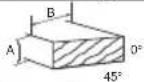 | 70 x 155 mm | |
| 45° 45° | 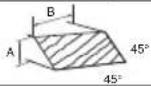 | 40 x 155 mm |
IVa
natural_image
Technical line drawing of a mechanical assembly with no visible text or symbolsIVb
a b
natural_image
Technical line drawing of a mechanical assembly with levers and workpiece (no text or symbols)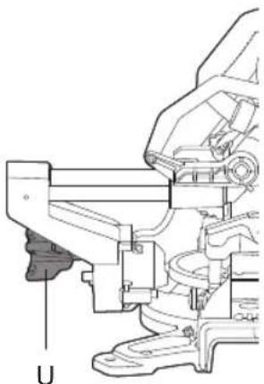
natural_image
Technical line drawing of a mechanical assembly with no visible text or symbols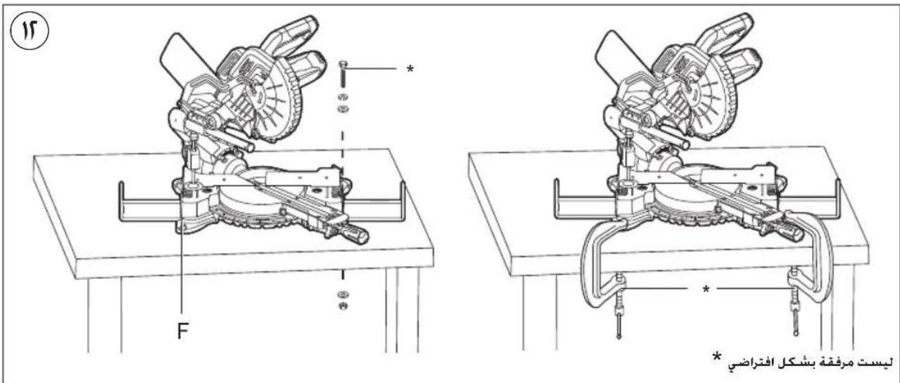

natural_image
Silhouette of a human figure holding a mechanical device, no text or symbols visible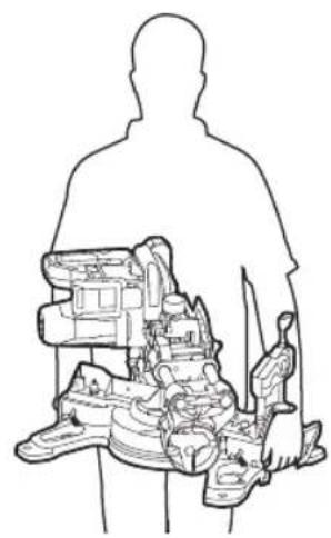
natural_image
Silhouette of a person holding a device with internal components (no text or symbols visible)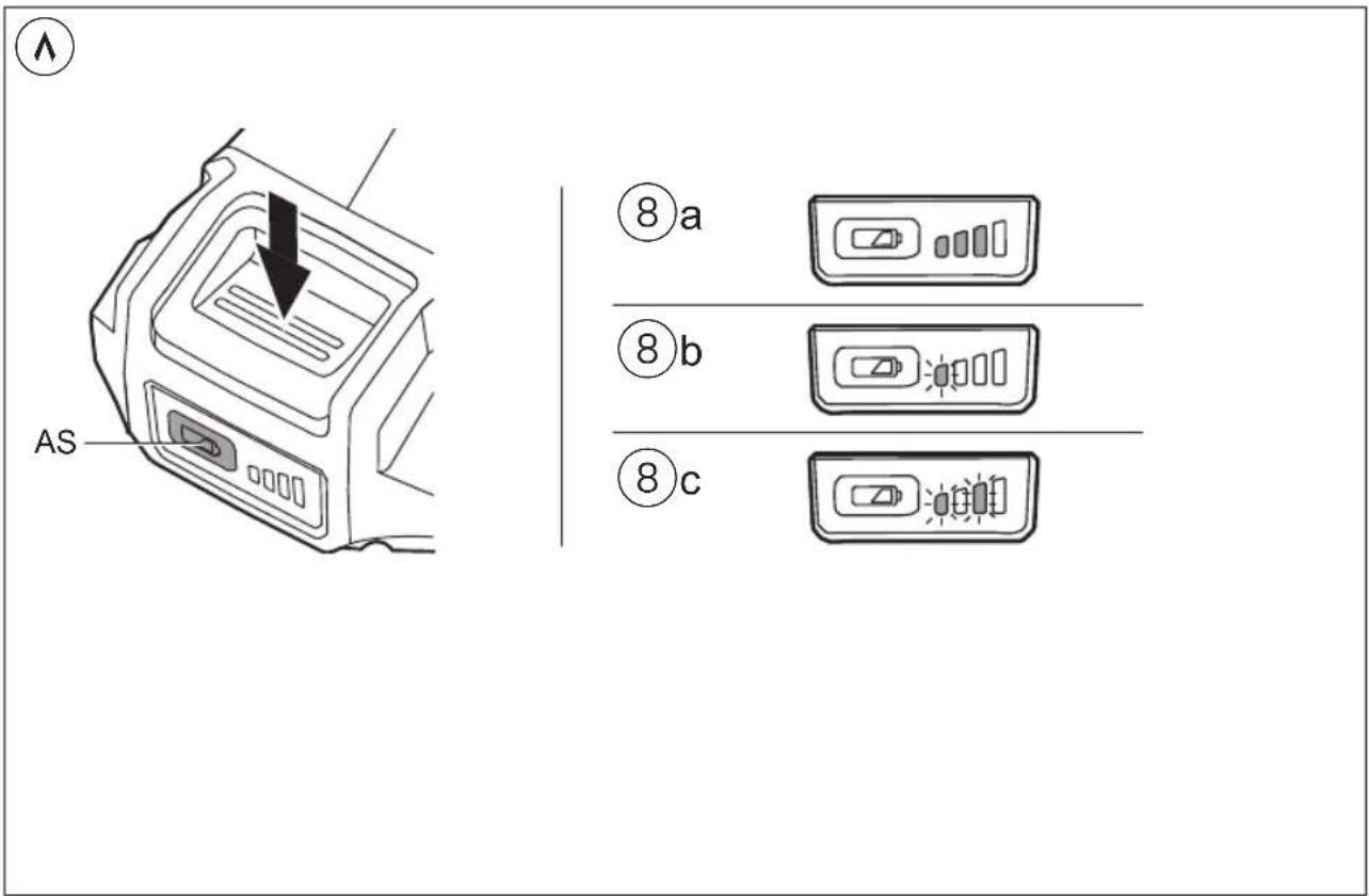
natural_image
Icon of a person reading a document inside a circle, with a small number 1 in the top-left corner (no text or symbols on the icon itself)
natural_image
Icon of a person wearing headphones inside a circle, with a small icon in the top-left corner (no text or symbols)

natural_image
Technical illustration of a mechanical cutting machine with visible blades and levers (no text or symbols)


- 3590
- GB
- Cordless sliding mitre saw 3590 INTRODUCTION
- TECHNICAL DATA①
- TOOL ELEMENTS ⑦
- SAFETY
- GENERAL POWER TOOL SAFETY WARNINGS
- Save all warnings and instructions for future reference.
- 1) WORK AREA SAFETY
- 2) ELECTRICAL SAFETY
- 3) PERSONAL SAFETY
- SAFETY INSTRUCTIONS FOR MITRE SAWS
- ADDITIONAL SAFETY INSTRUCTIONS
- GENERAL
- BEFORE USE
- ACCESSORIES
- DURING USE
- LASER RADIATION
- AFTER USE
- BATTERIES
- EXPLANATION OF SYMBOLS ON TOOL
- USE
- AD
- head 21a
- APPLICATION ADVICE
- MAINTENANCE / SERVICE
- ENVIRONMENT
- NOISE
- F
- CONSEILS D'APPLICATION
- DODATNE SIGURNOSNE UPUTE
- OPĆENITO
- OPŠTA
- PRE UPOTREBE
- PRIBÓR
- LASERSKO ZRAČENJE
- NAKON UPOTREBE
- BATERIJE
- NURGASAAGIDE OHUTUSJUHISED
- TECHNINIAI DUOMENYS ①
- IRANKIO DALYS⑦
Brand : SKIL
Model : 3590 AA
Category : Saw