
JS314901 - Saw SKIL - Free user manual and instructions
Find the device manual for free JS314901 SKIL in PDF.

| Product Type | Jigsaw |
| Brand | Skil |
| Model | JS314901 |
| Power Supply | 120 V~, 60 Hz, 6 A |
| No-load Speed | 800-3200 min⁻¹ |
| Stroke | 23 mm |
| Cutting Angle | 0° to 45° (left/right tilt) |
| Cutting Capacity (wood) | 85 mm |
| Cutting Capacity (aluminum) | 16 mm |
| Cutting Capacity (metal) | 6 mm |
| Orbital Action | Yes, 4 settings (0-3) |
| Lighting | LED Work Light |
| Dust Blower | Yes, slide switch (on/off) |
| Blade Change | Tool-free, lever cover |
| Switch Lock | Yes, lock button for continuous operation |
| Speed Adjustment | Rotary knob, 6 positions (1-6) |
| Handle | Rubberized, non-slip |
| Weight | Approx. 2.5 kg |
| Dimensions (L x W x H) | Approx. 27 x 8 x 23 cm |
| Compatible Blade Type | T-shank or U-shank, standard |
| Maintenance | Cleaning with dry compressed air, brush inspection every 2-6 months |
| Warranty | 1 year (household use), 90 days (professional use) |
Frequently Asked Questions - JS314901 SKIL
User questions about JS314901 SKIL
0 question about this device. Answer the ones you know or ask your own.
Ask a new question about this device
Download the instructions for your Saw in PDF format for free! Find your manual JS314901 - SKIL and take your electronic device back in hand. On this page are published all the documents necessary for the use of your device. JS314901 by SKIL.
USER MANUAL JS314901 SKIL
natural_image
Black and white line drawing of a SKIL power tool with no visible text or symbols on the device itselfGeneral Power Tool Safety Warnings 3-4
Safety Warnings for Jigsaws 4
Additional Safety Warnings ....5
Symbols 6-9
Get to Know Your Jigsaw 10
Specifications 10
Operating Instructions 11-17
Maintenance....18
Extension Cords 19
Troubleshooting 20
Limited Warranty of Skil Consumer Portable, Benchtop and Hd and Shd Heavy Duty Power Tools....21
WARNING
- Some dust created by power sanding, sawing, grinding, drilling and other construction activities contains chemicals known to the State of California to cause cancer, birth defects or other reproductive harm. Some examples of these chemicals are:
- Lead from lead-based paints.
– Crystalline silica from bricks, cement, and other masonry products.
– Arsenic and chromium from chemically-treated lumber. - Your risk from these exposures varies, depending upon how often you do this type of work. To reduce your exposure to these chemicals:
- Work in a well-ventilated area.
- Work with approved safety equipment, such as dust masks that are specially designed to filter out microscopic particles.
- Avoid prolonged contact with dust from power sanding, sawing, grinding, drilling, and other construction activities. Wear protective clothing and wash exposed areas with soap and water. Allowing dust to get into your mouth or eyes or to lie on the skin may promote absorption of harmful chemicals.
GENERAL POWER TOOL SAFETY WARNINGS

Read all safety warnings, instructions, illustrations and specifications provided with this power tool. Failure to follow all instructions listed
below may result in electric shock, fire and/or serious injury.
SAVE ALL WARNINGS AND INSTRUCTIONS FOR FUTURE REFERENCE.
The term “power tool” in the warnings refers to your mains-operated (corded) power tool or battery-operated (cordless) power tool.
Work area safety
Keep work area clean and well lit. Cluttered or dark areas invite accidents.
Do not operate power tools in explosive atmospheres, such as in the presence of flammable liquids, gases or dust. Power tools create sparks which may ignite the dust or fumes.
Keep children and bystanders away while operating a power tool. Distractions can cause you to lose control.
Electrical safety
Power tool plugs must match the outlet. Never modify the plug in any way. Do not use any adapter plugs with earthed (grounded) power tools. Unmodified plugs and matching outlets will reduce risk of electric shock.
Avoid body contact with earthed or grounded surfaces, such as pipes, radiators, ranges and refrigerators. There is an increased risk of electric shock if your body is earthed or grounded.
Do not expose power tools to rain or wet conditions. Water entering a power tool will increase the risk of electric shock.
Do not abuse the cord. Never use the cord for carrying, pulling or unplugging the power tool. Keep cord away from heat, oil, sharp edges or moving parts. Damaged or entangled cords increase the risk of electric shock.
When operating a power tool outdoors, use an extension cord suitable for outdoor use. Use of a cord suitable for outdoor use reduces the risk of electric shock.
If operating a power tool in a damp location is unavoidable, use a ground fault circuit interrupter (GFCI) protected supply. Use of a GFCI reduces the risk of electric shock.
Personal safety
Stay alert, watch what you are doing and use common sense when operating a power tool. Do not use a power tool while you are tired or under the influence of drugs, alcohol or medication. A moment of inattention while operating power tools may result in serious personal injury.
Use personal protective equipment. Always wear eye protection. Protective equipment such as a dust mask, non-skid safety shoes, hard hat or hearing protection used for appropriate conditions will reduce personal injuries.
Prevent unintentional starting. Ensure the switch is in the off-position before connecting to power source and/or battery pack, picking up or carrying the tool. Carrying power tools with your finger on the switch or energising power tools that have the switch on invites accidents.
Remove any adjusting key or wrench before turning the power tool on. A wrench or a key left attached to a rotating part of the power tool may result in personal injury.
Do not overreach. Keep proper footing and balance at all times. This enables better control of the power tool in unexpected situations.
Dress properly. Do not wear loose clothing or jewellery. Keep your hair and clothing away from moving parts. Loose clothes, jewellery or long hair can be caught in moving parts.
If devices are provided for the connection of dust extraction and collection facilities, ensure these are connected and properly used. Use of dust collection can reduce dust-related hazards.
Do not let familiarity gained from frequent use of tools allow you to become complacent and ignore tool safety principles. A careless action can cause severe injury within a fraction of a second.
Power tool use and care
Do not force the power tool. Use the correct power tool for your application. The correct power tool will do the job better and safer at the rate for which it was designed.
Do not use the power tool if the switch does not turn it on and off. Any power tool that cannot be controlled with the switch is dangerous and must be repaired.
Disconnect the plug from the power source and/or remove the battery pack, if detachable, from the power tool before making any adjustments, changing accessories, or storing power tools. Such preventive safety measures reduce the risk of starting the power tool accidentally.
Store idle power tools out of the reach of children and do not allow persons unfamiliar with the power tool or these instructions to operate the power tool. Power tools are dangerous in the hands of untrained users.
Maintain power tools and accessories. Check for misalignment or binding of moving parts, breakage of parts and any other condition that may affect the power tool's operation. If damaged, have the power tool repaired before use. Many accidents are caused by poorly maintained power tools.
Keep cutting tools sharp and clean. Properly maintained cutting tools with sharp cutting edges are less likely to bind and are easier to control.
Use the power tool, accessories and tool bits etc. in accordance with these instructions, taking into account the working conditions and the work to be performed. Use of the power tool for operations different from those intended could result in a hazardous situation.
Keep handles and grasping surfaces dry, clean and free from oil and grease. Slippery handles and grasping surfaces do not allow for safe handling and control of the tool in unexpected situations.
Service
Have your power tool serviced by a qualified repair person using only identical replacement parts. This will ensure that the safety of the power tool is maintained.
SAFETY WARNINGS FOR JIGSAWS
Hold the power tool by insulated gripping surfaces, when performing an operation where the cutting accessory may contact hidden wiring or its own cord. Cutting accessory contacting a "live" wire may make exposed metal parts of the power tool "live" and could give the operator an electric shock.
Use clamps or another practical way to secure and support the workpiece to a stable platform. Holding the workpiece by hand or against your body leaves it unstable and may lead to loss of control.
ADDITIONAL SAFETY WARNINGS
Secure material before cutting. Never hold it in your hand or across legs. Small or thin material may flex or vibrate with the blade, causing loss of control.
Do not drill, fasten or break into existing walls or other blind areas where electrical wiring may exist. If this situation is unavoidable, disconnect all fuses or circuit breakers feeding this worksite.
Never leave the trigger locked "ON". Before plugging the tool in, check that the trigger lock is "OFF". Accidental start-ups could cause injury.
Be aware of the location and setting of the switch "Lock-ON" button. If the switch is locked "ON" during the use, be ready for emergency situations to switch it "OFF", by first pulling the trigger then immediately releasing it without pressing the "Lock-ON" button.
Keep hands away from cutting area. Do not reach under the material being cut. The proximity of the blade to your hand is hidden from your sight.
Do not use dull or damaged blades. Bent blade can break easily or cause kickback.
Before starting to cut, turn tool "ON" and allow the blade to come to full speed. Tool can chatter or vibrate if blade speed is too slow at beginning of cut and possibly kickback.
Always wear safety goggles or eye protection when using this tool. Use a dust mask or respirator for applications which generate dust.
Make certain all adjusting screws and the blade holder are tight before making a cut. Loose adjusting screws and holders can cause the tool or blade to slip and loss of control may result.
When removing the blade from the tool avoid contact with skin and use proper protective gloves when grasping the blade or accessory. Accessories may be hot after prolonged use.
GFCI and personal protection devices like electrician's rubber gloves and footwear will further enhance your personal safety.
Do not use AC only rated tools with a DC power supply. While the tool may appear to work, the electrical components of the AC rated tool are likely to fail and create a hazard to the operator.
Keep handles dry, clean and free from oil and grease. Slippery hands cannot safely control the power tool.
Develop a periodic maintenance schedule for your tool. When cleaning a tool be careful not to disassemble any portion of the tool since internal wires may be misplaced or pinched or safety guard return springs may be improperly mounted. Certain cleaning agents such as gasoline, carbon tetrachloride, ammonia, etc. may damage plastic parts.
Risk of injury to user. The power cord must only be serviced by a SKIL Factory Service Center or Authorized SKIL Service Station.
SYMBOLS
Safety Symbols
The purpose of safety symbols is to attract your attention to possible dangers. The safety symbols and the explanations with them deserve your careful attention and understanding. The symbol warnings do not, by themselves, eliminate any danger. The instructions and warnings they give are no substitutes for proper accident prevention measures.

Be sure to read and understand all safety instructions in this Operator's Manual, including all safety alert symbols such as "DANGER,"
"WARNING," and "CAUTION" before using this tool. Failure to following all instructions listed below may result in electric shock, fire, and/or serious personal injury.
| The definitions below describe the level of severity for each signal word. Please read the manual and pay attention to these symbols. | |
 | This is the safety alert symbol. It is used to alert you to potential personal injury hazards. Obey all safety messages that follow this symbol to avoid possible injury or death. |
 | DANGER indicates a hazardous situation which, if not avoided, will result in death or serious injury. |
 | WARNING indicates a hazardous situation which, if not avoided, could result in death or serious injury. |
 | CAUTION, used with the safety alert symbol, indicates a hazardous situation which, if not avoided, will result in minor or moderate injury. |
Damage Prevention and Information Messages
These inform the user of important information and/or instructions that could lead to equipment or other property damage if they are not followed. Each message is preceded by the word "NOTICE", as in the example below:
NOTICE: Equipment and/or property damage may result if these instructions are not followed.

natural_image
Icon of a person wearing glasses inside a circle (no text or symbols)
The operation of any power tools can result in foreign objects being thrown into your eyes, which can result
in severe eye damage. Before beginning power tool operation, always wear safety goggles or safety glasses with side shields and a full face shield when needed. We recommend a Wide Vision Safety Mask for use over eyeglasses or standard safety glasses with side shields. Always use eye protection which is marked to comply with ANSI Z87.1.
SYMBOLS (CONTINUED)
IMPORTANT: Some of the following symbols may be used on your tool. Please study them and learn their meaning. Proper interpretation of these symbols will allow you to operate the tool better and safer.
| Symbol Name | Designation/Explanation | |
| V Volts Voltage (potential) | ||
| A Amperes Current | ||
| Hz Hertz Frequency (cycles per second) | ||
| W Watt Power | ||
| kg Kilograms Weight | ||
| min Minutes Time | ||
| s Seconds Time | ||
| ∅ | Diameter | Size of drill bits, grinding wheels, etc. |
| n_0 | No load speed | Rotational speed, at no load |
| n Rated speed | Maximum attainable speed | |
| .../min | Revolutions or reciprocation per minute | Revolutions, strokes, surface speed, orbits, etc. per minute |
| 0 Off position | Zero speed, zero torque... | |
| 1,2,3,...I,II,III, | Selector settings | Speed, torque or position settings. Higher number means greater speed |
| 0 | Infinitely variable selector with off | Speed is increasing from 0 setting |
| → | Arrow | Action in the direction of arrow |
| ~ | Alternating current | Type or a characteristic of current |
| --- | Direct current | Type or a characteristic of current |
| ~ | Alternating or direct current | Type or a characteristic of current |
| □ | Class II tool | Designates Double Insulated Construction tools. |
| ⊕ | Earthing terminal | Grounding terminal |
 | Li-ion RBRC seal | Designates Li-ion battery recycling program |
 | Ni-Cad RBRC seal | Designates Ni-Cad battery recycling program |
| Symbol Name Designation/Explanation | ||
 | Read manual symbol Alerts user to read manual | |
 | Wear eye protection symbol | Always wear safety goggles or safety glasses with side shields and a full face shield when operating this product. |
SYMBOLS (CERTIFICATION INFORMATION)
IMPORTANT: Some of the following symbols for certification information may be used on your tool. Please study them and learn their meaning. Proper interpretation of these symbols will allow you to operate the tool better and more safely.
| Symbol Designation/Explanation | |
 | This symbol designates that this tool is listed by Underwriters Laboratories. |
 | This symbol designates that this tool is recognized by Underwriters Laboratories. |
 | This symbol designates that this tool is listed by Underwriters Laboratories, to United States and Canadian Standards. |
 | This symbol designates that this tool is listed by the Canadian Standards Association. |
 | This symbol designates that this tool is listed by the Canadian Standards Association, to United States and Canadian Standards. |
 | This symbol designates that this tool is listed by the Intertek Testing Services, to United States and Canadian Standards. |
 | This symbol designates that this tool complies to NOM Mexican Standards. |
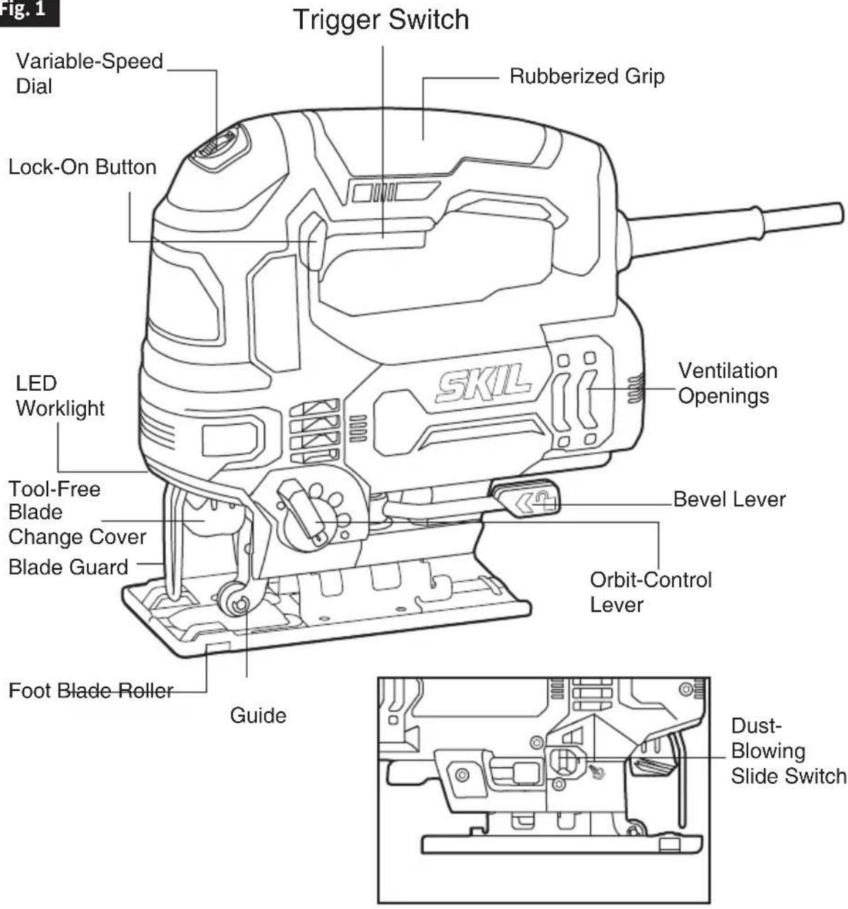
GET TO KNOW YOUR JIGSAW
Fig. 1
SPECIFICATIONS
| General | |
| Model No. JS314901 | |
| Power Input 120V~,60Hz,6A | |
| No-Load Speed (n0) 800-3200/min | |
| Stroke Length 7/8”(23mm) | |
| Cutting Angle 0 | ^0 ; 45^0 |
| Sawing capacity in wood 3-3/8 in.(85mm) | |
| Sawing capacity in aluminum 21/32 in. | (16mm) |
| Sawing capacity in metal 15/64 in. (6mm) | |
OPERATING INSTRUCTIONS
Tool-Free Blade Installation
WARNING
To prevent personal injury, always disconnect the plug from the power source before assembling parts, making adjustment, or changing blades.
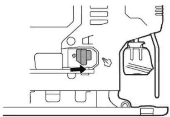
- Lift the tool-free blade change cover up and insert the blade (teeth facing the cutting direction) into the slot of the tool-free blade change holder (Fig. 2).
- Release the tool-free blade change cover to lock the blade in place.
- Pull down on the blade to verify that the blade is securely locked in place.
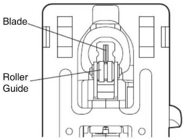
NOTICE: When inserting the saw blade, the back of the blade must rest in the groove of the guide roller (Fig. 3).
NOTICE: The tool accepts most commonly available T-shank and U-shank blades.
- To remove the blade, lift the tool-less blade change cover up and carefully remove the blade.
Fig. 2
Tool-Free Blade Change Cover
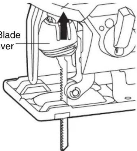
Fig. 3
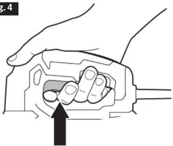
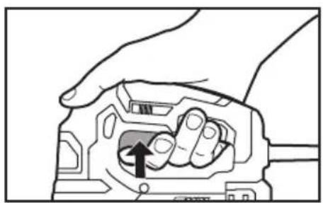
Trigger Switch
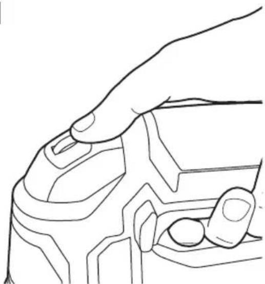
The tool can be turned "ON" or "OFF" by squeezing or releasing the trigger (Fig. 4).
Fig. 4
natural_image
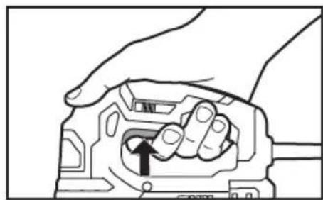
Illustration of a hand holding a mechanical component with an arrow indicating force or movement (no text or symbols present)"Lock-on" Button
The "Lock-on" button located in the handle of your tool allows for continuous operation at maximum SPM without depressing the trigger.
If you press the "Lock-on" button while the trigger switch is depressed, the switch will be locked in the operating position. To release the "Lock-on" button, press and release the trigger switch (Fig. 5).
Fig. 5
Trigger switch"lock-on" "Lock-on" release
natural_image
Hand holding a mechanical component with an arrow indicating rotation (no text or symbols)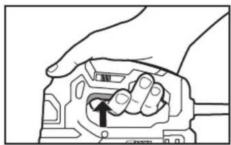
natural_image
Hand holding a mechanical component with an arrow indicating a specific part (no text or symbols present)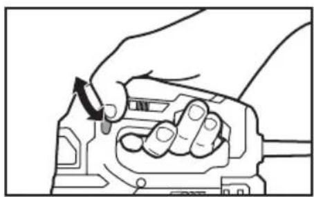
natural_image
Hand holding a mechanical component with a directional arrow indicating rotation (no text or symbols)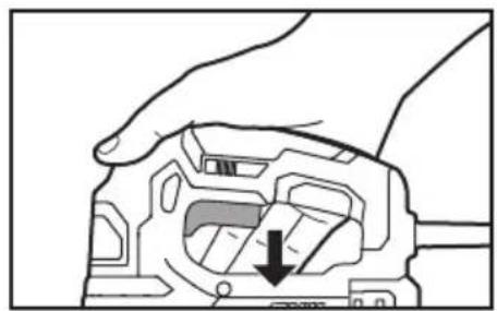
natural_image
Hand holding a mechanical component with a downward arrow indicating a specific part (no text or symbols present)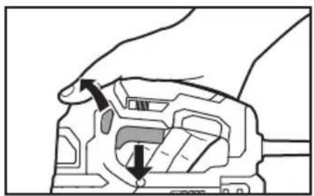
natural_image
Diagram of a hand holding a mechanical component with arrows indicating force or movement (no text or symbols present)Adjusting the Cutting Speed Using the Variable-Speed Dial
NOTICE: Determine the optimum speed for cutting your workpiece by making a trial cut in a scrap piece of the same material. Experience will help you to determine the best results for a particular application. However, as a rule, use slower speeds for harder, denser materials, and faster speeds for softer material.
The variable-speed feature of this jigsaw enhances the cutting performance and saves the blade from undue wear.
Use the variable-speed dial to adjust the speed of the blade. Turn the dial from setting 1 to setting 6 to increase the speed and from setting 6 to setting 1 to decrease the speed (Fig. 6).
Fig. 6
natural_image
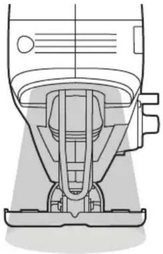
Line drawing of a hand gripping a mechanical component (no text or symbols)LED Work Light
The LED work light is located on the front of the saw in the tool housing. It will illuminate when the variable-speed trigger switch is depressed. This provides additional light on the surface of the work piece for operation in lower-light areas (Fig. 7).
The LED work light will turn off when the variable-speed trigger switch is released.
Fig. 7
natural_image
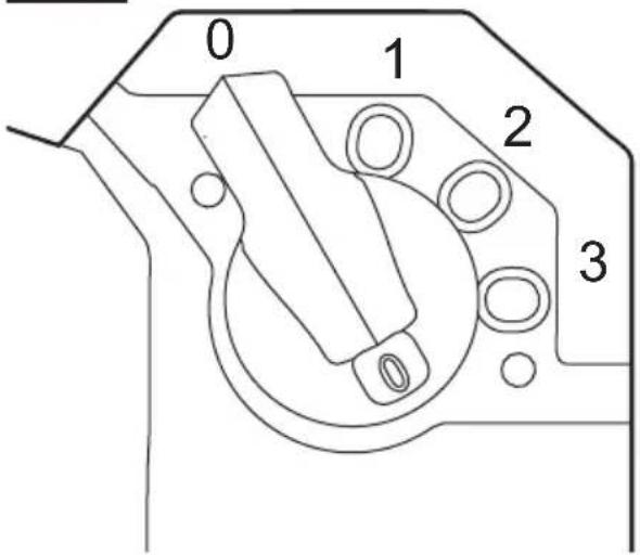
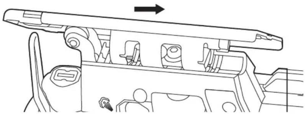
Technical line drawing of a mechanical device with no visible text or symbolsOrbital Action
This saw is equipped with an orbital control that allows you to choose the best cutting action for your material.
Simply turn the lever to the desired position for the type of cut you are making.
Turn the lever to a higher setting to increase the orbital action. Turn the lever to a lower setting to decrease the orbital action.
There are four orbital action cutting settings that may be chosen, according to different types of material (Fig. 8).
Setting 0: accurate cutting in all materials (straight and curved cuts).
Setting 1: fast cutting in metal (straight cuts only).
Setting 2: fast cutting in plastic (straight cuts only).
Setting 3: fast cutting in hard wood (straight cuts only).
Fig. 8
NOTICE: Always make test cuts in scrap material first to determine the best setting.
NOTICE: Always select "0" when sawing splinter-sensitive material.
NOTICE: In order to reach full orbital action. The blade must be facing straight forward, the back of the blade must be resting in the groove of the roller, and the foot must be positioned all the way forward. Orbital action is not detectable when the saw is running freely. The saw must be cutting in order for orbital action to occur. The cutting speed is easier to see when cutting thicker material.
WARNING
To reduce the risk of injury, always allow the jig saw to come to a complete stop before changing the orbital function setting.
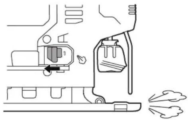
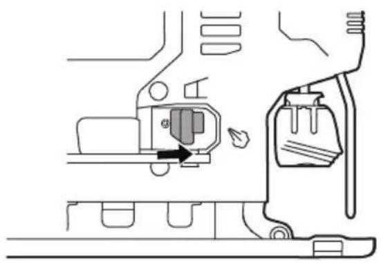
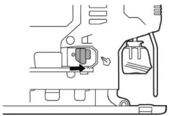
Dust-Blowing Slide Switch
To blow sawdust, move the switch to the blowing setting 0 (Fig. 9).
To turn off the blowing function, move the switch to setting 1 (Fig. 10).
WARNING
To reduce the risk of injury, always allow the jig saw to come to a complete stop before changing the dust blowing setting.
Fig. 9
natural_image
Diagram of a mechanical device with a valve and exhaust pipe, showing no text or symbolsFig. 10
natural_image
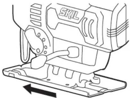
Technical line drawing of a mechanical component with no visible text or symbolsAdjusting the Foot Bevel Angle
Pivot the bevel lever to unlock the foot (Fig.11).
Fig. 11

natural_image
Technical line drawing of a SKIL electric shaver with mounting base (no text or symbols)
natural_image
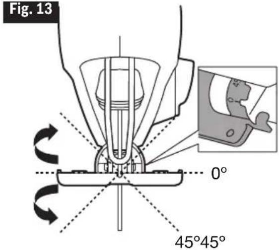
Line drawing of a sewing machine with a base plate and internal components (no text or symbols)Move the foot slightly forward and tilt it to the required angle ( 0^ or 45^ ) using the scale ( 0^ or 45^ ) that is marked on the base bracket. The foot has indents at 0^ and 45^ (tilt left or right) for easy angle setting (Fig. 12 & Fig. 13).
Fig. 12
natural_image
Line drawing of a sewing machine component with no visible text or symbolsFig. 13

Move the foot slightly backward until the lock pins locate in the indents at 0° or 45° (Fig. 14 & Fig. 15).
Fig. 14
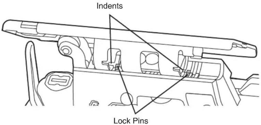
Fig. 15
natural_image
Technical line drawing of a mechanical assembly with no visible text or symbolsMake sure that the lock pins are situated in the indents at the angle you select. Pivot the bevel lever back to lock the foot.
Cutting Tips
Face the good side of the material down and secure it in a bench vise or clamp it down. Draw cutting lines or designs on the side of the material facing up towards you. Then place the front edge of the saw foot on the work and align the blade with the line to be cut. Hold the jigsaw firmly, turn it on, and press down (to keep the saw foot flat against the work) as you slowly push the saw in the direction of the cut.
Gradually increase the cutting rate, cutting close to the line (unless you want to leave stock for finish sanding). As you cut you may need to adjust or relocate the vise or clamps to keep the work stable. Do not force the saw or the blade teeth may rub and wear without cutting and the blade may break. Let the saw do most of the work. When following curves, cut slowly so the blade can cut through cross grain. This will give you an accurate cut and will prevent the blade from wandering.
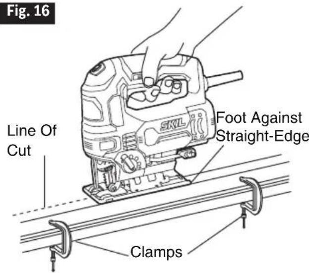
Cutting with a Straightedge
Use a roughcut blade whenever possible. Clamp a straightedge on the work parallel to the line of cut and flush with the side of the saw foot. (Either first mark the line of cut and then position the straightedge parallel and at the same distance as between the blade and the side edge of the foot or first mark the side edge of the foot and then clamp the straightedge on the mark and parallel to the cut line (Fig. 16).
As you cut, keep the saw foot edge flush against the straightedge and flat on the workpiece (Fig. 16).
Metal Cutting
When cutting metal, clamp the material down securely. Be sure to move the saw along slowly. Use lower speeds. Do not twist, bend, or force the blade. If the saw jumps or bounces, use a blade with finer teeth. If the blade seems clogged when cutting soft metal, use a blade with coarser teeth.
- For easier cutting, lubricate the blade with a stick of cutting wax, if available, or cutting oil when cutting steel.
- Thin metal should be sandwiched between two pieces of wood or tightly clamped on a single piece of wood (wood on top of the metal). Draw the cut lines or design on the top piece of wood.
- When cutting aluminum extrusion or angle iron, clamp the work in a bench vise and saw close to the vise jaws.
- When sawing tubing and the diameter is larger than the blade is deep, cut through the wall of the tubing and then insert the blade into the cut rotating the tube as you saw.
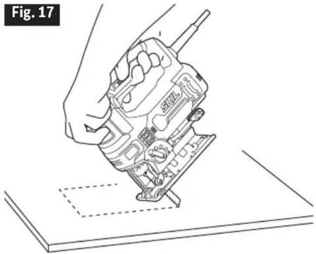
Plunge Cutting
Plunge cutting is useful and time-saving when making rough openings in softer materials. It is not necessary to drill a hole for an inside or pocket cut. Do not try to plunge cut into hard materials, such as steel.
- Draw lines for the opening,
-
Hold the saw firmly and tilt it forward so that the toe of the saw foot rests on the work, but with the blade well clear of the work.
-
Start the motor, and then very gradually lower the blade.
-
When the blade touches, continue pressing down on the toe of the saw foot while slowly
pivoting the saw like a hinge until the blade cuts through and the foot rests flat on the work.
- Then saw ahead on the line of cut line.
We do not recommend plunge cutting with a scroll blade (Fig.17).
To make sharp corners, cut up to the corner, then back up slightly before rounding the corner. After the opening is complete, go back to each corner and cut it from the opposite direction to square it off. Do not try to plunge cut into hard materials such as steel.
natural_image
Line drawing of a hand using a walkie-talkie to press or install electronic components on a flat surface (no text or symbols)MAINTENANCE
Service

Preventive maintenance performed by unauthorized personnel may result in misplacing of internal wires and components which could
cause serious hazard. We recommend that all tool service be performed by a SKIL Factory Service Center or Authorized SKIL Service Station.
Tool Lubrication
Your SKIL tool has been properly lubricated and is ready to use. It is recommended that tools with gears be regreased with a special gear lubricant at every brush change.
Carbon Brushes
The brushes and commutator in your tool have been engineered for many hours of dependable service. To maintain peak efficiency of the motor, we recommend every two to six months the brushes be examined. Only genuine SKIL replacement brushes specially designed for your tool should be used.
Cleaning

To avoid accidents always disconnect the tool from the power supply before cleaning or performing any maintenance. The tool may be
cleaned most effectively with compressed dry air. Always wear safety goggles when cleaning tools with compressed air.
Ventilation openings and switch levers must be kept clean and free of foreign matter. Do not attempt to clean by inserting pointed objects through openings.

Certain cleaning agents and solvents damage plastic parts. Some of these are: gasoline, carbon tetrachloride, chlorinated cleaning solvents,
ammonia and household detergents that contain ammonia.
Storage
Store the tool indoors in a place that is inaccessible to children. Keep away from corrosive agents.
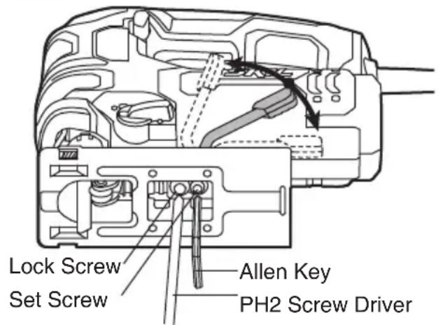
If the bevel lever loosens during use, set the tightness of the bevel lever (Fig.18)
- Place the bevel lever in the middle position.
- Loosen the lock screw with a PH2 screw driver (not included) counter clockwise.
- Tighten the set screw with a 4mm Allen key (not included) counter clockwise.
NOTICE: The set screw uses left hand thread.
- Tighten the lock screw with PH2 screw driver clockwise.
- Tighten the bevel lever.
Fig. 18
EXTENSION CORDS

If an extension cord is necessary, a cord with adequate size conductors that is capable of carrying the current necessary for your tool must be
used. This will prevent excessive voltage drop, loss of power or overheating. Grounded tools must use 3-wire extension cords that have 3-prong plugs and receptacles.
NOTICE: The smaller the gauge number, the heavier the cord.
RECOMMENDED SIZES OF EXTENSION CORDS 120 VOLT ALTERNATING CURRENT TOOLS
| Tool's Ampere Rating | Cord Size in A.W.G. Wire Sizes in mm2 | |
| Cord Length in Feet Cord Length in Meters | ||
| 25 50 100 150 15 30 60 120 | ||
| 3-6 18 | 16 16 14 0.75 .075 1.5 2.5 | |
| 6-8 18 | 16 14 12 0.75 1.0 2.5 4.0 | |
| 8-10 18 | 16 14 12 0.75 1.0 2.5 4.0 | |
| 10-12 16 | 16 14 12 1.0 2.5 4.0 — | |
| 12-16 14 | 12 — — — — — — | |
TROUBLESHOOTING
| Problem Cause | Remedy | |
| Tool will not start | 1. The power cord is not plugged in.2. The power source fuse or circuit breaker tripped.3. Cord damaged. 3. Inspect the4. Burned out switch. 4. Have switch replaced by an Authorized SKIL Service Center or Service Station. | 1. Plug tool into power source.2. Replace the fuse or reset the tripped circuit breaker. (If the product repeatedly causes the circuit or fuse to trip/blow, discontinue use immediately and have it serviced by an Authorized SKIL Service Center or Service Station.)cord for damage. If damaged, have the cord replaced by an Authorized SKIL Service Center or Service Station. |
| Tool does not come up to speed | 1. Extension cord has insufficient gauge or is too long.2. Low house voltage. 2. Contact your electric company. | 1. Replace with adequate extension cord (Refer to the part of “EXTENSION CORDS”). |
| Excessive vibration | 1. Blade is bent. 1. Discard blade and use different blade.2. Blade not secure in blade holder. | 2. See OPERATING INSTRUCTIONS section, “Tool-free Blade Installation”. |
LIMITED WARRANTY OF SKIL CONSUMER PORTABLE, HD, SHD AND MAG HEAVY DUTY POWER TOOLS
Chervon North America (“Seller”) warrants to the original purchaser only, that all SKIL consumer portable, HD, SHD and MAG Heavy Duty power tools will be free from defects in material or workmanship for a period of one year from date of purchase. SKIL consumer portable power tool models will be free from defects in material or workmanship for a period of ninety days if the tool is used for professional use.
SELLER'S SOLE OBLIGATION AND YOUR EXCLUSIVE REMEDY under this Limited Warranty and, to the extent permitted by law, any warranty or condition implied by law, shall be the repair or replacement of parts, without charge, which are defective in material or workmanship and which have not been misused, carelessly handled, or misrepaired by persons other than Seller or Authorized Service Station. To make a claim under this Limited Warranty, you must return the complete product, transportation prepaid, to any SKIL Factory Service Center or Authorized Service Station. For Authorized SKIL Power Tool Service Stations, please visit www.Registermyskil.com or call 1-877-SKIL-999 (1-877-754-5999).
THIS LIMITED WARRANTY DOES NOT APPLY TO ACCESSORY ITEMS SUCH AS CIRCULAR SAW BLADES, DRILL BITS, ROUTER BITS, JIGSAW BLADES, SANDING BELTS, GRINDING WHEELS AND OTHER RELATED ITEMS.
ANY IMPLIED WARRANTIES SHALL BE LIMITED IN DURATION TO ONE YEAR FROM DATE OF PURCHASE. SOME STATES IN THE U.S., SOME CANADIAN PRO V INCES DO NOT ALLOW LIMITATIONS ON HOW LONG AN IMPLIED WARRANTY LASTS, SO THE ABOVE LIMITATION MAY NOT APPLY TO YOU.
IN NO EVENT SHALL SELLER BE LIABLE FOR ANY INCIDENTAL OR CONSEQUENTIAL DAMAGES (INCLUDING BUT NOT LIMITED TO LIABILITY FOR LOSS OF PROFITS) ARISING FROM THE SALE OR USE OF THIS PRODUCT. SOME STATES IN THE U.S. AND SOME CANADIAN PROVINCES DO NOT ALLOW THE EXCLUSION OR LIMITATION OF INCIDENTAL OR CONSEQUENTIAL DAMAGES, SO THE ABOVE LIMITATION OR EXCLUSION MAY NOT APPLY TO YOU.
THIS LIMITED WARRANTY GIVES YOU SPECIFIC LEGAL RIGHTS, AND YOU MAY ALSO HAVE OTHER RIGHTS WHICH VARY FROM STATE TO STATE IN THE U.S., PROVINCE TO PROVINCE IN CANADA AND FROM COUNTRY TO COUNTRY
THIS LIMITED WARRANTY APPLIES ONLY TO PRODUCTS SOLD WITHIN THE UNITED STATES OF AMERICA, CANADA AND THE COMMONWEALTH OF PUERTO RICO. FOR WARRANTY COVERAGE WITHIN OTHER COUNTRIES, CONTACT YOUR LOCAL SKIL DEALER OR IMPORTER.
© Chervon North America, 1203 E. Warrenville Rd, Naperville, IL 60563. 08/19
TABLE DES MATIÈRES
natural_image
Icon of a person wearing glasses inside a circle (no text or symbols)AVERTISSEMENT
natural_image
Illustration of a hand holding a mechanical component with an arrow indicating upward motion (no text or symbols)natural_image
Hand holding a mechanical component with an arrow indicating rotation (no text or symbols)Déverrouillage
natural_image
Hand holding a mechanical component with an arrow indicating a specific part (no text or symbols present)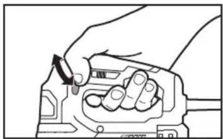
natural_image
Illustration of hands using a tool to adjust or install a mechanical component (no text or symbols visible)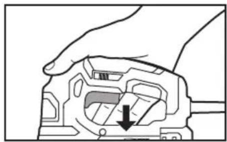
natural_image
Hand holding a mechanical component with a downward arrow indicating a specific part (no text or symbols present)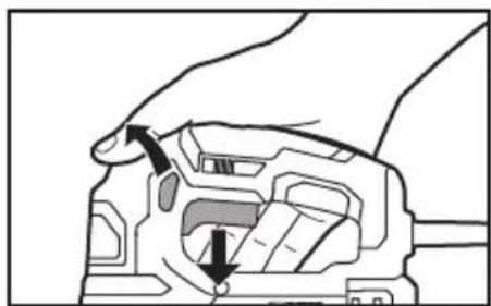
natural_image
Diagram of a mechanical component with arrows indicating motion or force direction (no text or symbols)natural_image
Line drawing of a hand gripping a mechanical component (no text or symbols)natural_image
Technical line drawing of a mechanical device with no visible text or symbolsCoupe orbitale
natural_image
Diagram of a mechanical device with internal components and exhaust plume (no text or symbols)Fig. 10
natural_image
Technical line drawing of a mechanical component with no visible text or symbolsnatural_image
Technical line drawing of a sewing machine component (no text or symbols visible)
natural_image
Technical line drawing of a SKIL electric shaver with mounting base (no text or symbols)natural_image
Line drawing of a sewing machine component with no visible text or symbols
natural_image
Technical line drawing of a mechanical assembly with no visible text or symbolsnatural_image
Line drawing of a hand using a walkie-talkie to press or install electronic components on a flat surface (no text or symbols)ENTRETIEN
Entretien
AVERTISSEMENT
© Chervon North America, 1203 E. Warrenville Rd, Naperville, IL 60563.
08/19
ÍNDICE
natural_image
Icon of a person wearing glasses inside a circle (no text or symbols)ADVERTENCIA
natural_image
Illustration of a hand holding a mechanical component with an arrow indicating force or movement (no text or symbols present)Botón de bloqueo
natural_image
Hand holding a mechanical component with an arrow indicating rotation (no text or symbols)natural_image
Hand holding a mechanical component with an arrow indicating a specific part (no text or symbols present)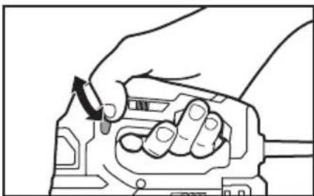
natural_image
Line drawing of a hand holding a mechanical component with a directional arrow indicating rotation (no text or symbols)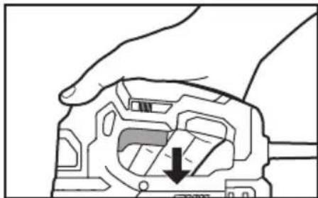
natural_image
Hand holding a mechanical component with a downward arrow indicating a specific part (no text or symbols present)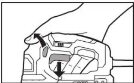
natural_image
Diagram of a hand holding a device with arrows indicating movement or force (no text or symbols present)natural_image
Line drawing of a hand gripping a mechanical component (no text or symbols)natural_image
Technical line drawing of a mechanical device with no visible text or symbolsAcción orbital
natural_image
Line drawing of a mechanical device with a valve and exhaust pipe, no text or symbols presentFig. 10
natural_image
Technical line drawing of a mechanical component with no visible text or symbolsnatural_image
Technical line drawing of a SKIL printer with mounting base (no text or symbols)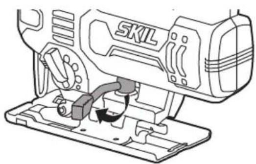
natural_image
Line drawing of a sewing machine with a base mount and internal components (no text or symbols)natural_image
Line drawing of a sewing machine component with no visible text or symbolsFig. 13
natural_image
Technical line drawing of a mechanical assembly with no visible text or symbolsnatural_image
Line drawing of a hand using a device to cut a component on a flat surface, no text or symbols presentMANTENIMIENTO
© Chervon North America, 1203 E. Warrenville Rd, Naperville, IL 60563.
08/19


- WARNING
- GENERAL POWER TOOL SAFETY WARNINGS
- SAVE ALL WARNINGS AND INSTRUCTIONS FOR FUTURE REFERENCE.
- Work area safety
- Electrical safety
- Personal safety
- Power tool use and care
- Service
- SAFETY WARNINGS FOR JIGSAWS
- ADDITIONAL SAFETY WARNINGS
- SYMBOLS
- Safety Symbols
- Damage Prevention and Information Messages
- SYMBOLS (CONTINUED)
- SYMBOLS (CERTIFICATION INFORMATION)
- GET TO KNOW YOUR JIGSAW
- OPERATING INSTRUCTIONS
- Tool-Free Blade Installation
- Trigger Switch
- "Lock-on" Button
- Adjusting the Cutting Speed Using the Variable-Speed Dial
- LED Work Light
- Orbital Action
- Dust-Blowing Slide Switch
- Adjusting the Foot Bevel Angle
- Cutting Tips
- Cutting with a Straightedge
- Metal Cutting
- Plunge Cutting
- MAINTENANCE
- Tool Lubrication
- Carbon Brushes
- Cleaning
- Storage
- If the bevel lever loosens during use, set the tightness of the bevel lever (Fig.18)
- EXTENSION CORDS
- RECOMMENDED SIZES OF EXTENSION CORDS 120 VOLT ALTERNATING CURRENT TOOLS
- LIMITED WARRANTY OF SKIL CONSUMER PORTABLE, HD, SHD AND MAG HEAVY DUTY POWER TOOLS
- TABLE DES MATIÈRES
- AVERTISSEMENT
- Coupe orbitale
- ENTRETIEN
- ÍNDICE
- ADVERTENCIA
- Botón de bloqueo
- Acción orbital
- MANTENIMIENTO
Brand : SKIL
Model : JS314901
Category : Saw