
RSG EX 1500 B - Milling machine Fein - Free user manual and instructions
Find the device manual for free RSG EX 1500 B Fein in PDF.

| Brand | Fein |
| Model | RSG EX 1500 B |
| Category | Milling machine (pipe milling machine) |
| Type | Partial explosion-proof electric pipe milling machine |
| Nominal voltage | 400 V (three-phase 3~, 50 Hz) |
| Nominal power | 1500 W |
| Motor speed at idle | 2860 rpm |
| Tool speed at idle | 35 rpm (version A) / 70 rpm (version B) |
| Feed rate | 40 mm/min (version A) / 80 mm/min (version B) |
| Max. tool diameter | 220 mm |
| Pipe diameter range | 250 – 1500 mm (RSG Ex 1500) / 250 – 3000 mm (RSG Ex 18) |
| Dimensions (L × H × W) | 974 × 334 × 450 mm (version A) / 1088 × 334 × 431 mm (version B) |
| Weight | 80 kg |
| Protection class | IP X4 |
| Type of protection | Partially explosion-proof (motor and switch ATEX) |
| Main functions | Cutting, milling and chamfering of steel or cast iron pipes |
| Automatic feed | Yes, via feed control lever (28) |
| Explosion-proof motor | ATEX compliant for zone 2 (with external control box) |
| Insulated handles | Yes (transport strap with insulated surfaces) |
| Maintenance | Gear oil drain, chain cleaning, lubrication of sliding surfaces |
| Included accessories | Transport container, tool case, crank, wrenches, chain tensioner, chains, etc. |
Frequently Asked Questions - RSG EX 1500 B Fein
User questions about RSG EX 1500 B Fein
0 question about this device. Answer the ones you know or ask your own.
Ask a new question about this device
Download the instructions for your Milling machine in PDF format for free! Find your manual RSG EX 1500 B - Fein and take your electronic device back in hand. On this page are published all the documents necessary for the use of your device. RSG EX 1500 B by Fein.
USER MANUAL RSG EX 1500 B Fein
natural_image
Technical line drawing of a mechanical assembly with gears, linkages, and housing (no text or symbols)RSG Ex 1500 A (**) 7 360 ...
RSG Ex 1500 B (**) 7 360 ...
RSG Ex 18 A (**) 7 360 ...
RSG Ex 18 B (**) 7 360 ...

A
natural_image
Technical line drawing of a mechanical assembly with no visible text or symbolsnatural_image
Technical line drawing of a mechanical device with no visible text or symbolsnatural_image
Technical line drawing of a mechanical or electrical component with mounting holes and a central circular dial (no text or symbols)Translation of the Original Instructions.
Symbols, abbreviations and terms used.
| Symbol, character Explanation | ||
 | ! | Observe the instructions in the text or graphic opposite! |
| [0ZX6] | Make sure to read the enclosed documents such as the Instruction Manual and the General Safety Instructions. | |
 | Use eye protection during operation. | |
 | Use ear protection during operation. | |
 | Use protective gloves during operation. | |
| [40AT] | General prohibition sign. This action is prohibited. | |
 | Do not reach in! | |
 | ! | Do not touch the rotating parts of the power tool. |
 | Do not reach into chains and sprockets! | |
 | Warning against sharp edges of application tools, such as the cutting edges of the cutter blades. | |
 | Hot surface! | |
| [08TK] | Gripping surface | |
 | Additional information. | |
 | Confirms the conformity of the power tool with the directives of the European Community. | |
 | Worn out power tools and other electrotechnical and electrical products should be sorted separately for environmental-friendly recycling. | |
 |  | Do not turn or screw the three securing screws. |
 | Applies only for China:The duration of environmental protection under normal use of the product is 10 years. | |
| (**) May contain numbers and letters | ||
Technical Data.
Order number 7 360 ... 7 360 ...
Design* RSG Ex 1500 A (**) RSG Ex 1500 B (***)
Order number 7 360 ... 7 360 ...
Design* RSG Ex 18 A (**) RSG Ex 18 B (**)
Voltage (U) 400 V 400 V
Frequency ( 50 Hz 50 Hz
Mains supply: 3 \~ (three-phase current) 3 \~ (three-phase current)
No-load speed ( n_0 )
| - Motor | 2860 rpm | 2860 rpm |
| - Application tools | 35 rpm | 70 rpm |
| Feed (J 40 mm/min) | 80 mm/min | |
| Rated power (P) | 1500 W | 1500 W |
| Power cord length (with plug) | ||
| - RSG Ex 1500 (**) | 2 × 20 m | 2 × 20 m |
| - RSG Ex 18 A/B (**) | 2 × 20 m | 2 × 20 m |
| Class of protection | +/-I | +/-I |
| Protection class | IP X4 | IP X4 |
*Electric motor and auxiliary switch in explosion-proof design (ATEX-compliant)
| Design® RSG Ex 1500 A (**) | ||
| RSG Ex 1500 B (**) | RSG Ex 18 A (**)RSG Ex 18 B (**) | |
| Dimensions: | ||
| - Weight (m) 80 kg | 80 kg | |
| - Max. tool ∅ | 220 mm | 220 mm |
| - Lmax. | 974 mm | 1088 mm |
| - Hmax. | 334 mm | 334 mm |
| - Bmax. | 450 mm | 431 mm |
| - B1 | 371 mm | 371 mm |
| - B2 | 201 mm | 201 mm |
| - B3 | 791 mm | 991 mm |
Intended Use of the Pipe Milling Machines.
The pipe milling machine is intended for cutting and milling free pipe ends and installed pipe sections made of steel or cast iron, as well as for chamfering pipe ends prior to welding them at construction sites or in the open. The pipe milling machine is for specialty companies and to be operated by specialists; it is not intended for continuous everyday use.
The complete pipe milling machine is not approved for explosion-protected areas.
The pipe milling machine is not intended for:
- use in areas with explosive atmospheres.
- use during heavy rain and work under water.
- use outside of the temperature range of -20°C to 40°C.
- for cutting explosive materials.
- for cutting combustible material.
EC Directive 94/9EC ATEX (Atmosphères Explosibles)
Please note that FEIN pipe milling machines of the type RSG Ex (**) are not approved for use in explosive atmospheres and therefore no EC type examination certificates exist for these pipe milling machines in accordance with Directive 94/9EC.
(Only two ATEX-compliant components are installed on the RSG Ex (**) pipe milling machines, being the electric motor and the auxiliary switch).
The ATEX directive applies only in the EC area.
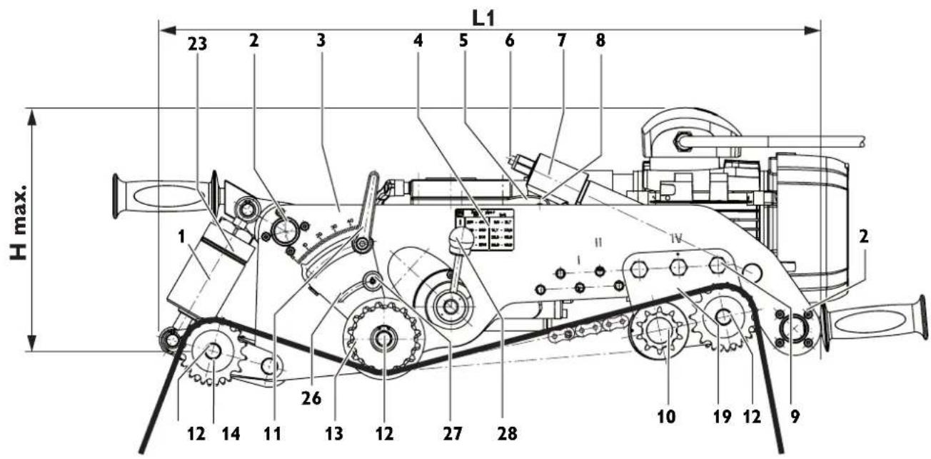
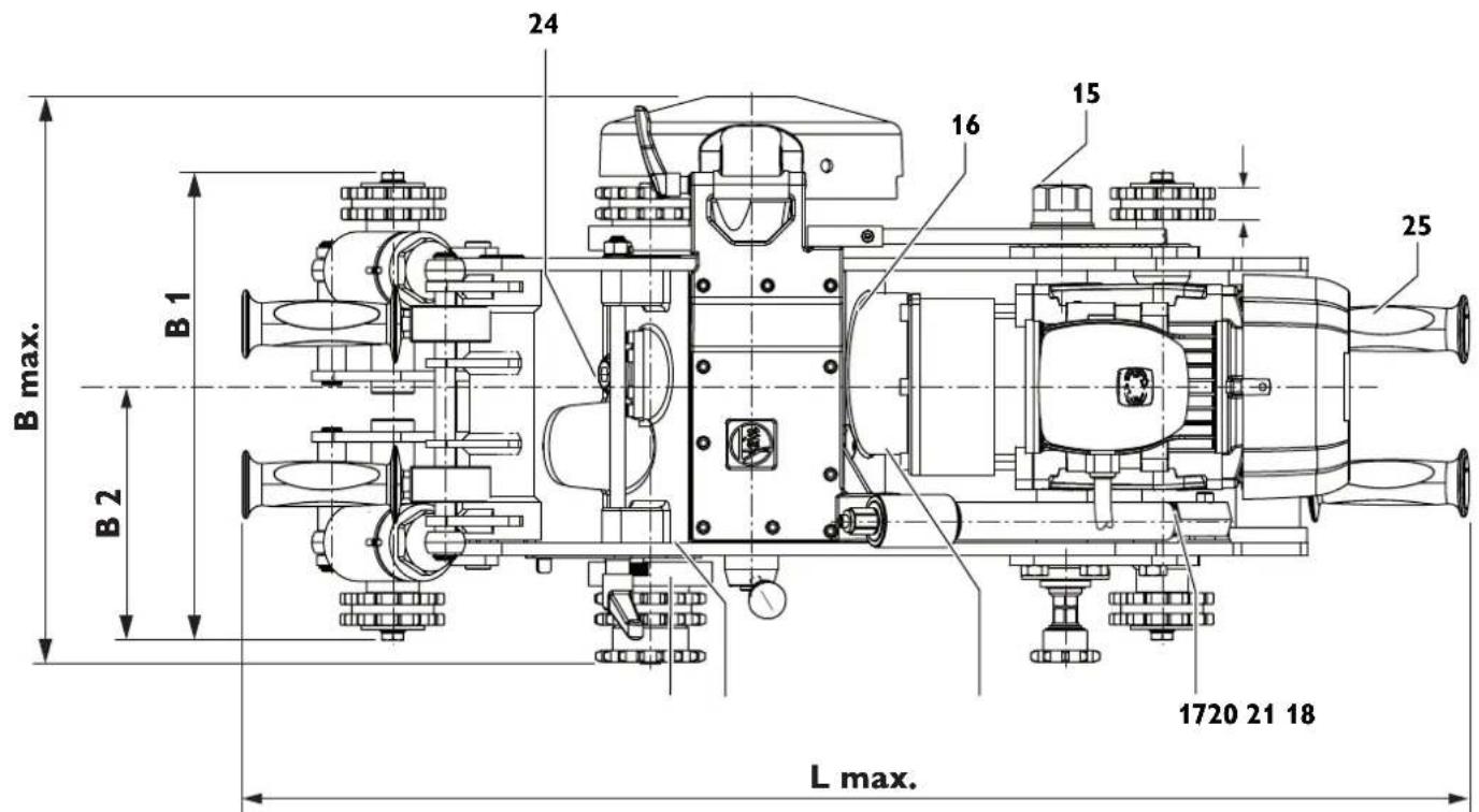
At a glance.
1 Tightening device
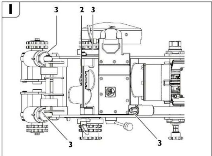
2 Fastening screw for side plate
3 Side plate
4 Information label
5 Bolt
6 Threaded spindle
7 Feed mechanism
8 Pan head screw for feed mechanism
9 Fitting screw
10 Running axle
11 Clamping lever
12 Hexagon bolt
13 Washer
14 Tightening axle
15 Nut
16 Tool spindle head
17 Pipe nut
18 Fastening screw for motor
19 Bracket
20 Drive sprocket
21 Transport shaft
22 Securing ring
23 Pin
24 Screw plug of tool spindle head
25 Carrying handle (insulated gripping surfaces)
26 Depth scale
27 Knurled nut
28 Feed switching lever
29 Chain-tensioner hexagon
30 Chain-tensioner disc
31 Securing screws of chain tensioner
32 Securing ring for chain link
33 Bolt of chain link
34 Carrying straps
For your safety.
General safety rules.
WARNING
Read all safety warnings, instructions, figures and technical data provided with power tool. Failure to follow the warnings
and instructions may result in electric shock, fire and/or serious injury.
Save all safety warnings and instructions for future reference.
The term "power tool" used in the safety instructions, refers to mains-powered power tools (with mains cable) and to battery-operated power tools (without mains cable).
1) Work area safety
a) Keep work area clean and well lit. Cluttered or dark areas invite accidents.
b) Do not operate power tools in explosive atmospheres, such as in the presence of flammable liquids, gases or dust. Power tools create sparks which may ignite the dust or fumes.
c) Keep children and bystanders away while operating a power tool. Distractions can cause you to lose control.
2) Electrical safety
a) Power tool plugs must match the outlet. Never modify the plug in any way. Do not use any adapter plugs with earthed (grounded) power tools. Unmodified plugs and matching outlets will reduce risk of electric shock.
b) Avoid body contact with earthed or grounded surfaces, such as pipes, radiators, ranges and refrigerators. There is an increased risk of electric shock if your body is earthed or grounded.
c) Do not expose power tools to rain or wet conditions. Water entering a power tool will increase the risk of electric shock.
d) Do not abuse the cord. Never use the cord for carrying, pulling or unplugging the power tool. Keep cord away from heat, oil, sharp edges or moving parts. Damaged or entangled cords increase the risk of electric shock.
e) When operating a power tool outdoors, use an extension cord suitable for outdoor use. Use of a cord suitable for outdoor use reduces the risk of electric shock.
f) If operating a power tool in a damp location is unavoidable, use a residual current device (RCD) protected supply. Use of an RCD reduces the risk of electric shock.
3) Personal safety
a) Stay alert, watch what you are doing and use common sense when operating a power tool. Do not use a power tool while you are tired or under the influence of drugs, alcohol or medication. A moment of inattention while operating power tools may result in serious personal injury.
b) Use personal protective equipment. Always wear eye protection. Protective equipment such as a dust mask, non-skid safety shoes, hard hat or hearing protection used for appropriate conditions will reduce personal injuries.
c) Prevent unintentional starting. Ensure the switch is in the off-position before connecting to power source and/or battery pack, picking up or carrying the tool. Carrying power tools with your finger on the switch or energising power tools that have the switch on invites accidents.
d) Remove any adjusting key or wrench before turning the power tool on. A wrench or a key left attached to a rotating part of the power tool may result in personal injury.
e) Do not overreach. Keep proper footing and balance at all times. This enables better control of the power tool in unexpected situations.
f) Dress properly. Do not wear loose clothing or jewellery. Keep your hair and clothing away from moving parts. Loose clothes, jewellery or long hair can be caught in moving parts.
g) If devices are provided for the connection of dust extraction and collection facilities, ensure these are connected and properly used. Use of dust collection can reduce dust-related hazards.
h) Do not let familiarity gained from frequent use of tools allow you to become complacent and ignore tool safety principles. A careless action can cause severe injury within a fraction of a second.
4) Power tool use and care
a) Do not force the power tool. Use the correct power tool for your application. The correct power tool will do the job better and safer at the rate for which it was designed.
b) Do not use the power tool if the switch does not turn it on and off. Any power tool that cannot be controlled with the switch is dangerous and must be repaired.
c) Disconnect the plug from the power source and/or remove the battery pack, if detachable, from the power tool before making any adjustments, changing accessories, or storing power tools. Such preventive safety measures reduce the risk of starting the power tool accidentally.
d) Store idle power tools out of the reach of children and do not allow persons unfamiliar with the power tool or these instructions to operate the power tool. Power tools are dangerous in the hands of untrained users.
e) Maintain power tools and accessories. Check for misalignment or binding of moving parts, breakage of parts and any other condition that may affect the power tool's operation. If damaged, have the power tool repaired before use. Many accidents are caused by poorly maintained power tools.
f) Keep cutting tools sharp and clean. Properly maintained cutting tools with sharp cutting edges are less likely to bind and are easier to control.
g) Use the power tool, accessories and tool bits etc. in accordance with these instructions, taking into account the working conditions and the work to be performed. Use of the power tool for operations different from those intended could result in a hazardous situation.
h) Keep handles and grasping surfaces dry, clean and free from oil and grease. Slippery handles and grasping surfaces do not allow for safe handling and control of the tool in unexpected situations.
5) Service
a) Have your power tool serviced by a qualified repair person using only identical replacement parts. This will ensure that the safety of the power tool is maintained.
Specific safety rules for pipe milling machines.
Observe the national regulations for prevention of accidents when starting-up, working on and maintaining the pipe milling machine.
Observe the statutory explosion-protection guidelines.
Ensure that the pipe being cut is firmly supported. Non-observance of this safety instruction can lead to serious injury or death.
Electrically-operated pipe milling machines (design RSG Ex [\*\*]).
The mains voltage and the voltage specification on the pipe milling machine must correspond.
The supply connection of the pipe milling machine must be protected with a 20 A fuse.
Check the power cord and, if necessary, the extension cable regularly!
Connect the pipe milling machine to the switchgear assembly only when the main switch is switched off.
The switchgear assembly must be accessible by the operator at all times.
Application.
Keep handles and gripping surfaces dry, clean, and free from oil and grease. Slippery handles and gripping surfaces do not allow safe operation and control of the machine in unexpected situations.
Hold power tool by insulated gripping surfaces only, because the cutting tool could cut into the machine's power cord. Contact with a "live" wire make exposed metal parts of tool "live" and shock the operator.
Do not overload the pipe milling machine. Use the right application tool for your work. Your work performance will be better and more safe when using the right application tool.
Do not use a pipe milling machine with a defective switch. A pipe milling machine that can no longer be switched on or off is dangerous and must be repaired.
Disconnect the power supply before making machine settings or changing application tools. This safety measure prevents accidental starting of the pipe milling machine.
Do not allow persons unfamiliar with the pipe milling machine or these instructions to operate the machine. Pipe milling machines are dangerous in the hands of untrained users.
Maintain the pipe milling machine at regular intervals. Inspect the pipe milling machine for possible damage as well as for other factors that may interfere with the operation of the pipe milling machine. Repair a pipe milling machine not in proper order before usage. Many preventable accidents are caused by poorly maintained pipe milling machines.
Use the pipe milling machine, the accessories as well as application tools according to the instructions in this manual, whereby the working conditions and the activities to be carried out are to be taken into consideration. The use of pipe milling machines for applications different from those intended could result in hazardous situations.
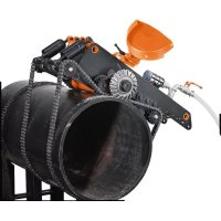
Operation (see figure A).
The pipe milling machine cuts and mills exposed pipe sections and laid pipes with the use of cutting application tools. It is clamped to the outside of the pipe by its tightening device and moves around the pipe with automatic working feed. The cutting tools used are metal circular saw blades and profile cutters with cutting edges are made of HSS steel or carbide, depending on the pipe material.
- The cutting depth is adjusted by the tool spindle head (16), which is seated in both side plates (3); it can be pivoted, and is adjusted by means of the threaded spindle (6).
- The transport shaft (21), which creates the operational feed motion via the transport wheels, is driven by the tool spindle via 2 worm gear stages.
- The feed motion can be switched on or off via the feed switching lever (28). A safety clutch protects the feed gearing against overload.
The bearing of the tool spindle is particularly rigid. The oil-bath lubricated main gearbox for driving the tool spindle consists of a planetary and worm gear stage.
The gearing unit is dimensioned in such a manner that occasional seizing of the chain can be endured without damage. All transmission shafts run in anti-friction bearings.
The machine frame with the axles has the task of guiding the clamped pipe milling machine on the pipe and transmitting the cutting and feed forces.
- The adaptation to the respective pipe outside diameter is achieved by adjusting the running axle (10).
The tightening chains are sized in length by putting together identical chain segments.
The number of chain segments required, respectively the length of the tightening chains depends on the exterior pipe diameter.
Transport.
B
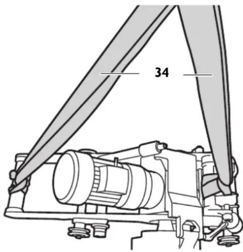

Danger of injury when transporting the pipe milling machine. Only transport the pipe milling machine using the supplied carrying straps (34) or by at least three persons.
Before Starting Operation.

Danger of injury from unexpected movements of the workpiece. Before processing, secure the workpiece against unexpected movements. When
processing the workpiece, there is a risk of unexpected rolling away, falling down or shifting of the workpiece.

The machine may only be operated when in technically proper condition. Each time before starting-up the machine, check it for worn or damaged insert tools and components. Worn or damaged application tools and components be replaced immediately with new ones.
Preliminary work on the pipe to be machined.
- Underlay/support pipes being cut in the storage area in such a manner that the application tool is not jammed.
- For pipes already laid, a clearance of at least 50 cm must be maintained measured from the pipe exterior to the pit wall at every point along a length of 1 m.
- The pipe surface being machined must be free of dirt and soil. Remove soft protective coatings on the machining surface beforehand.
- The cutting tool must be selected according to the pipe material, the required machining shape and cooling lubrication.
- Remove the welding seams in the area of the sprockets and chains.
For more information, please contact your coolant/lubricant supplier. (compressed-air cooling-lubricant device)
Lubricating agent at 0°C:
- Lubricating agent BIOCUT 1L - 3 21 32 039 00 0
- Lubricating agent BIOCUT 5L - 3 21 32 040 00 0
Lubricating agent up to 25°C:
- Lubricating agent 1L - 3 21 32 042 00 0
- Lubricating agent 5L - 3 21 32 043 00 0
Preliminary work on the pipe milling machine (see figure A).
- Release clamping lever (11)
- Raise the tool spindle head (16) at the feed mechanism (7) using the hand crank (in tool box).
- Remove the fitting screws (9) and the refit the running axle (10) to the current exterior pipe diameter in accordance with Table (4).
- Mount/tighten the fitting screws (9) again.
RSG Ex 1500 A/B (**)
| P | D[mm] [inch] | |
| I 250 – 400 9.8 | 15.7 | |
| II 400 – 600 15.7 | -23.6 | |
| III 600 – 900 23.6 | -35.3 | |
| IV 900 – 1500 35.3 | -58.9 |
RSG Ex 18 A/B (**)
| P | D[mm] [inch] | |
| I 250 – 400 9.6 | -15.7 | |
| II 400 – 600 15.7 | -23.6 | |
| III 600 – 800 23.6 | -31.5 | |
| IV 800 – 1000 31.5 | -39.4 | |
| V 1000 – 1300 39.4 | -51.2 | |
| VI 800 – 3000 51.2 | -118.1 |
P: Position of running axle
D: Pipe diameter
- Extend the tightening devices (1) for the clamping chains by turning the spring tube so that there is sufficient clamping travel after the pipe milling machine has been set down.

Arrange the clamping chains to fit the exterior pipe diameter.

Position the pipe milling machine on the pipe and secure it with lifting gear in order to prevent slipping off or shifting.

Assemble guide chain with chain tensioner to match the exterior pipe diameter.
- Affix the guide chain 10 mm clear aside of the clamping chain opposite of the milling tool. The clearance from the bolt of the guide chain to the bolt of the clamping chain is 10 mm.
- Check the clearance at the circumference at least three times.
Clamping the pipe milling machine on the pipe.
Mounting the chain links.
- On both sides of the pipe milling machine, place the still open chain links over the pipe.
- Raise the pipe milling machine and slide the chain links under the sprockets (20), so that the chain links engage in the sprocket teeth after lowering the pipe milling machine.
- Guide the free ends of the chain links over the sprockets of tightening axle (14) and bracket (19).
- Lock both ends of the chain links with bolt (3 02 17 216 00 4) and secure with the two securing rings (4 26 34 020 00 5).
Tensioning the chain links (see figure A).
- Firstly, lightly snug the chain links against the pipe by turning the two spring tubes (1). For exact alignment, move the pipe milling machine back and forth a few times in the circumferential direction of the pipe.
- Tension the chain links by turning the spring tubes until the pin (23 figure A) in the slotted hole of the spring tube is inside the groove cut in the circumference.
- Observe the position of the pin during the cutting process. If the pipe is out of round, you must either retighten or loosen the tension. Remove all 4 handles prior to the cutting.

Danger of accidents!
Do not tension the spring tube beyond this point!
natural_image
Pure mechanical assembly diagram showing a shaft and housing component without any text or symbolsMounting Application Tools.

Danger of injury
Danger of injury from unintentional switching on. Pull the mains plug before mounting the application tool.

Danger of injury
Danger of cuts from the sharp cutting edges of the application tool. Wear protective gloves when mounting and dismounting the application tool.

Danger of injury
Danger of burns from the hot application tool. Wear protective gloves when dismounting the application tool.

Wear protective gloves.
Only use application tools with cutting edges in proper condition.
- Before bringing the pipe milling machine into contact with the pipe, clean the tool spindle as well as all fitting and contact surfaces.
- Mount the application tool with spacers.
- Firmly tighten the tool clamping nut.
Starting Operation.
Pipe milling machine:
natural_image
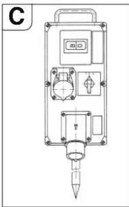
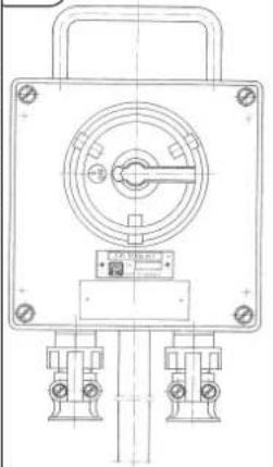
Technical line drawing of a mechanical device with no visible text or symbolsConnect a switchgear assembly on the line side of pipe milling machines with electric drives that have the following components:
-Main switch/reversing switch
-Motor protection switch
-Undervoltage release
-Plug connectors
The main switch is used as an on switch and for reversing the rotation direction. The motor protection switch and the undervoltage release are a unit. In case of overload, the motor protection switch cuts out; in the event of a mains voltage failure, the undervoltage release disconnects the pipe milling machine from the mains to prevent unintentional restarting.
The pipe milling machine is put back into operation by actuating the motor protection switch.
The switchgear assembly must be positioned so that tor at all times.
it can be reached by the operator at all times.
Pipe milling machine in partially explosion-proof design:
natural_image
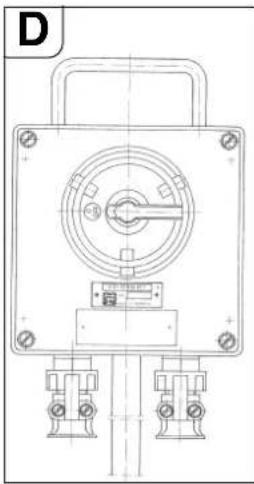
Technical line drawing of a mechanical device with mounting holes and central hub (no text or symbols)Upstream of the switchgear assembly, use a switch box with an additional on/off switch to operate the pipe milling machine In Zone 2 hazardous areas. The switch box must be positioned so that it can be reached by the operator at all times.
Danger of explosion
The switchgear assembly is to be set up outside of zone 2.
Operation.

Danger of injury
The protection hood must be completely closed and locked during operation!

Danger of injury from chips/swarf being thrown about
These can lead to injuries. Make sure that there are no persons in the danger area.

Danger of fire from chips/swarf being thrown about
Make sure that there are no easily flammable objects in the danger area.

Danger of injury
Danger of injury from parts being thrown about when the pipe milling machine is switched on. Remove the hand crank each time before using the pipe milling machine.
Starting procedure
For pipe milling machines with electric motor, ensure that the rotation direction of the cutting tool is correct. The rotation direction can be reversed with the reversing switch on the switchgear assembly.

Danger of injury
Danger of injury from rotating parts while the machine is running. The danger area of the machine may only be accessed for adjustment work in compliance with the safety-relevant measures.
- Shut off the feed gearing via the feed switching lever (28).
- Switch the pipe milling machine on.
- Release clamping lever (11) and with the hand crank, pivot the running saw blade as deep as possible into the pipe. The deeply immersed saw blade stabilizes the cutting process.
- When milling, select the least possible tool contact. The removal rate increases with increasing cutting depth.
- Immerse application tool approx. 3 mm deeper than necessary, then return to required depth, this disengages the application tool.
- When using the depth scale, allow the application tool to slightly graze against the pipe surface. Loosen the knurled nut (27) and set the pointer (28) to 0. Tighten knurled nut (27) again. The feed depth can be read off the scale.
- Switch the pipe milling machine off.
- Afterwards, lock the setting by tightening clamping lever (11).
- Switch the pipe milling machine on again.
- Switch on the feed gearing via the feed switching lever (28).
- If the motor power is sufficient, cut through the pipe wall in one cut.
- Laid pipes can give way during sawing and jam the application tool in the gap. Therefore, the supplied wedges must be driven into the gap behind the saw tool at regular intervals. In hazardous areas, use wedges (6 33 05 013 00 2) (RSG Ex 1500 A/B (^**) supplied accessories) and a hammer made of non-sparking material.
- Avoid overloading the pipe milling machine.
- An overload is given when the motor speed drops noticeably while the running application tool is plunged in.
- At the same time, this results in a drop of the cutting performance.
- Affix workpiece (cut-off pipe) to protect it from falling down.
For thick-walled pipes (s > 10 mm), the weld joint must be milled in several runs.
The congruent cutting process is influenced by the following factors:
- Alignment of the pipe milling machine when starting,
- Geometric deviation of the pipe from the circular or cylindrical shape,
- Sharpness of the application tool,
- Hardness of the material.
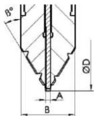
The pipe milling machine is adjusted such that for pipe diameters of 300 mm and 600 mm, the beginning and end of the cutting line approximately coincide.
Due to the eccentricity of the guide shaft, the adjustment mark (24, see Fig. E) is only binding for the two diameters indicated. For larger pipe diameters, readjustment may be necessary.
Return motion of the pipe milling machines (RSG Ex [\*\*]).
Possible damage!
Before retracting the pipe milling machine, make sure that the application tool is retracted so that damage to the tool and the gearbox is avoided.
- Shut off the feed gearing via the feed switching lever (28).
- Release clamping fever (11).
- Retract the application tool.
- Set main switch/reversing switch to "0" (off) position.
- Set reversing switch to return motion.
- Tighten clamping lever (11).
- Switch on the feed gearing via the feed switching lever (28).
The pipe milling machine is not suitable for making cuts in return motion!
Notes on cooling and lubrication.
Possible damage!
During milling, the application tool must be cooled and lubricated. Insufficient cooling and lubrication can cause chips to jam. This can lead to tool breakage.
Observe the manufacturer's information/notes on the coolant being used
- Always cut gray cast iron pipes dry without cooling lubricant.
- Cool the saw blade or cutter with soapy water when cutting unalloyed steel pipes.
Adjusting the running accuracy.
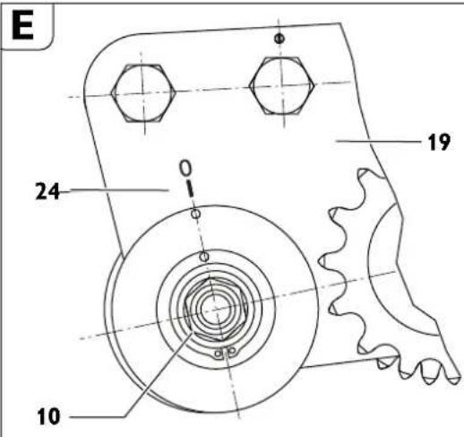
- Loosen nut (15, see figure A); wrench size 46.
- Turn axle (10) with respect to bracket (19).
- Tighten nut (15).
By turning the running axle (10) clockwise (towards the application tool), the application tool will move rightwards (the viewing direction is equal to the movement direction of the pipe milling machine).
When turning the running axle counterclockwise, the application tool will move leftwards.
Installing additional chain links.
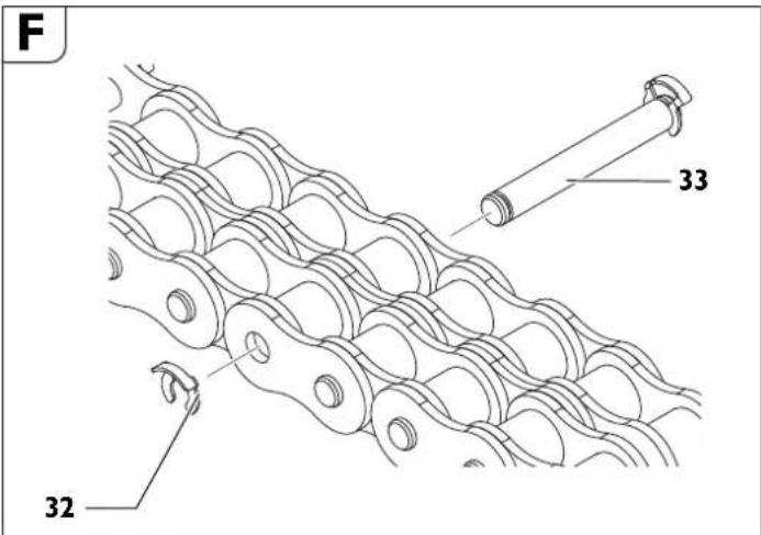

Additional chain links may only be installed at the positions intended for this.
- Remove the securing ring (32).
- Remove the bolt (33).
- Install the desired number of chain links.
- Different sizes of chain links are included in the accessories of the machine.
- Insert the bolt (33).
- Mount a new securing ring (32).
Clamping the pipe milling machine to a pipe.
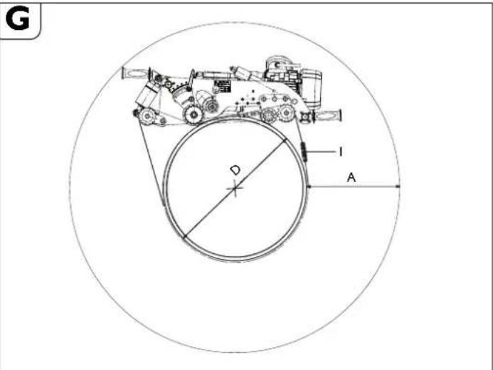
"A" required working space at the greatest cutting depth.
“D” Outer diameter of pipe
“i” Number of chain pieces for pipe diameter "D".
RSG Ex 1500 A/B
| Position of running axle | D[mm] [mm] | A[mm] [mm] | R e length per side | Total qchain length | i^\# |
| 1 | 250 | 400 | 1427 | 2854 | 5 |
| 300 | 392 | 1525 | 3050 | 5 | |
| 350 | 384 | 1632 | 3264 | 6 | |
| 400 | 378 | 1744 | 3488 | 6 | |
| 2 | 400 | 381 | 1782 | 3564 | 6 |
| 450 | 375 | 1898 | 3796 | 7 | |
| 500 | 369 | 2019 | 4038 | 7 | |
| 550 | 364 | 2144 | 4288 | 7 | |
| 600 | 360 | 2273 | 4546 | 8 | |
| 3 | 600 | 362 | 2302 | 4604 | 8 |
| 650 | 357 | 2433 | 4866 | 8 | |
| 700 | 352 | 2566 | 5132 | 9 | |
| 750 | 348 | 2702 | 5404 | 9 | |
| 800 | 344 | 2840 | 5680 | 10 | |
| 850 | 340 | 2862 | 5724 | 10 | |
| 900 | 337 | 3001 | 6002 | 10 |
| 4 | 900 | 348 | 3142 | 6284 | 10 |
| 950 | 345 | 3284 | 6568 | 11 | |
| 1000 | 342 | 3428 | 6856 | 11 | |
| 1050 | 340 | 3464 | 6928 | 11 | |
| 1100 | 337 | 3607 | 7214 | 12 | |
| 1150 | 335 | 3751 | 7502 | 12 | |
| 1200 | 333 | 3896 | 7792 | 13 | |
| 1300 | 331 | 4062 | 8124 | 13 | |
| 1400 | 329 | 4338 | 8676 | 14 | |
| 1500 | 328 | 4355 | 8710 | 14 | |
| *Order number 3 02 31 013 02 7 consisting of 10 pieces of chain, each 635 mm long. | |||||
RSG Ex 18 A/B
| Position of running axle | D A Required chain [mm] [mm] | length per side | Total chain length | i* | |
| 1 | 250 | 587 | 1427 | 2854 | 5 |
| 300 | 576 | 1525 | 3050 | 5 | |
| 350 | 564 | 1632 | 3264 | 6 | |
| 400 | 553 | 1744 | 3488 | 6 | |
| 2 | 400 | 522 | 1782 | 3564 | 6 |
| 450 | 511 | 1898 | 3796 | 7 | |
| 500 | 501 | 2019 | 4038 | 7 | |
| 550 | 492 | 2144 | 4288 | 7 | |
| 600 | 483 | 2273 | 4546 | 8 | |
| 3 | 600 | 453 | 2302 | 4604 | 8 |
| 650 | 445 | 2433 | 4866 | 8 | |
| 700 | 437 | 2566 | 5132 | 9 | |
| 750 | 429 | 2702 | 5404 | 9 | |
| 800 | 422 | 2840 | 5680 | 10 | |
| 4 | 800 | 396 | 2862 | 5724 | 10 |
| 850 | 393 | 3001 | 6002 | 10 | |
| 900 | 390 | 3142 | 6284 | 10 | |
| 950 | 386 | 3284 | 6568 | 11 | |
| 1000 | 383 | 3428 | 6856 | 11 | |
| 5 | 1 | 390 | 34640 | 69Q8 | 11 |
| 1050 | 387 | 3607 | 7214 | 12 | |
| 1100 | 385 | 3751 | 7502 | 12 | |
| 1150 | 382 | 3896 | 7792 | 13 | |
| 1200 | 379 | 4062 | 8124 | 13 | |
| 1300 | 374 | 4338 | 8676 | 14 | |
| 6 | 1 | 383 | 43550 | 8700 | 14 |
| 1400 | 382 | 4651 | 9302 | 15 | |
| 1500 | 378 | 4950 | 9900 | 16 | |
| 1600 | 373 | 5250 | 10500 | 17 | |
| 1700 | 369 | 5553 | 11106 | 18 | |
| 1800 | 366 | 5857 | 11714 | 19 | |
| 1900 | 362 | 6162 | 12324 | 20 | |
| 2000 | 359 | 6468 | 12936 | 21 | |
| 2100 | 356 | 6775 | 13550 | 22 | |
| 2200 | 353 | 7083 | 14166 | 23 | |
| 2300 | 350 | 7391 | 14782 | 24 | |
| 2400 | 348 | 7700 | 15400 | 25 | |
| 2500 e | 346 d | 8009 c | 16018 a | 26 | |
| 2600 | 343 | 8319 | 16638 | 27 | |
| 2700 | 341 | 8629 | 17258 | 28 | |
| 2800 | 339 | 8940 | 17880 | 29 | |
| 2900 | 337 | 9251 | 18502 | 30 | |
| 3000 | 335 | 9562 | 19124 | 31 | |
| *Order number 3 02 31 013 02 7 consisting of 10 pieces of chain, each 635 mm long. | |||||
To achieve optimal chain pre-tension, you may want to use the 31.75 mm half chain pieces included in the tool kit.
Example:
For a pipe diameter of D=400 mm, 6 chain pieces (order number 3 02 31 013 02 7) are required.
Track guidance through guide chain
H
Assemble the length of the guide chain in accordance with the Table.
To achieve optimal chain pre-tension, you may want to use the 31.75 mm half chain pieces included in the tool kit.
Chain length of guide chain
| Pipe diameter | Chain length | Chain pieces | |||
| [mm] | [mm] | mm | 63.5 | mm | |
| 250 710 1 1 | 1 | ||||
| 300 870 1 4 | 0 | ||||
| 350 1030 1 | 6 1 | ||||
| 400 1190 1 | 9 0 | ||||
| 450 1344 2 | 1 1 | ||||
| 500 1500 2 | 4 0 | ||||
| 550 1660 2 | 6 1 | ||||
| 600 1809 2 | 8 1 | ||||
| 650 1970 3 | 1 1 | ||||
| 700 2130 3 | 4 0 | ||||
| 750 2290 3 | 6 1 | ||||
| 800 2440 3 | 8 1 | ||||
| 850 2600 4 | 1 0 | ||||
| 900 2760 4 | 4 0 | ||||
| 950 2921 4 | 6 0 | ||||
| 1000 3079 | 4 8 1 | ||||
| 1100 3397 | 5 3 1 | ||||
| 1200 3714 | 5 8 1 | ||||
| 1300 4032 | 6 3 1 | ||||
| 1 4 | 0 | 0 4 | 3 3 | 0 6 | |
| 1 5 | 0 | 0 4 | 6 4 | 0 7 | |
Order number 3 02 31 034 01 0 (l = 635 mm)
Order number 3 02 31 036 01 0 (l = 63.5 mm)
Order number 3 02 31 035 01 0 (l = 31.7 mm)
- Fasten the guide chain to one of both chain pieces on the chain tensioner with chain bolt and securing ring.
- Thread the guide strand of the guide chain through below the two guide-chain sprockets (Fig. H).
- Fasten the free end of the guide chain to the chain tensioner with chain bolt and securing ring.
-
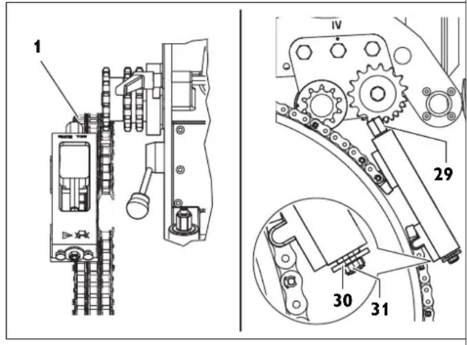
Snug the guide chain against the pipe by turning the hexagon at the chain tensioner (2).
-
Align the guide chain with a clearance of 10 mm (bolt of drive chain to bolt of guide chain) and check three times around the circumference.
- Tension the chain tensioner via the hexagon (29) until the washer (30) faces against the housing of the chain tensioner (tensioning range approx. 50 mm). (Max. tightening torque 50 Nm)
Caution! Danger of accidents! Do not turn or screw the three securing screws (31) on the face side. (see figure H)
Final work after each work assignment.
- Retract the application tool.
- Switch the pipe milling machine off.
- Remove the application tool.
- Dismount pipe milling machine from pipe.
Storing the pipe milling machine.
- Protect the external metal parts against corrosion.
- Store pipe milling machine at a dry location.
Maintenance and Repairs.
On maintenance and repairs.
For FEIN power tools and accessories in need of repair, please contact your FEIN after-sales service. The address can be found on the Internet under www.fein.com. The current spares parts list for this power tool can be found on our website at www.fein.com.
Use only original spare parts.
If required, you can change the following parts yourself: Application tools, handles, chain, chain links
The machine may only be operated when in technically proper condition. Worn or damaged application tools and components must be replaced immediately with new ones.
Danger of injury
through unintentional switching on.
Before any work on the pipe milling machine, pull the mains plug!
General information
Maintenance work may only be carried out by trained specialists.
The servicing and maintenance work basically include:
- Exterior cleaning of the pipe milling machine and clamping chains.
- Visual checking of the complete pipe milling machine.
- Changing the gearbox oil.
- Greasing the moving threads and chains.
- Greasing the guides of the tool spindle head in the clamping and transport device.
- Renewing the stickers and warning indications on the machine.
Maintenance of chain links
After removing coarse debris, carefully clean the link chains with benzine, kerosene or similar while moving the chain links.
To ensure lubrication, place the chains afterwards in viscous oil, e.g. SAE 140 gear oil, for several hours.
Danger of accidents! Before reviving the ck
Before reusing the chain links, carry out a thorough visual inspection to ensure that they are in proper condition. Replace damaged parts and missing securing rings.
Power supply cord
When the machine's power supply cord is damaged, it must be replaced by the manufacturer or their representative.
Feed mechanism (see figure A)
- Keep surface area of pipe nut (17) free from debris and any rust; always apply a light coat of grease.
- When changing gearbox oil, clean and grease moving threads.
Disassembly:
- Remove pan head screw (8).
- Pull bolt (5) out of lid.
- Afterwards, screw feed mechanism out of pipe nut using hand crank.
- Clean and grease the threaded parts (see section Lubricants and lubrication chart on page 19).
- Replace damaged scraper rings.
Assembly:
Assembly is carried out in reverse order. Do not damage scraper rings when assembling!
Tightening device
Avoid contamination of the threads on the eyebolts (3, Fig. 1) in the spring tube. Clean and grease threads as required.
Lubricants and lubrication chart
| Lubricating agentARAL oil Degol | Filling quantity Temperature range [°C] | Specification |
| BMB 460 2 liters 0 to +60 Gear oil, type | CLPF acc. to DIN15502 | |
| BMB 100 2 liters -20 to +40 |
Upon delivery, the tool spindle head is filled with ARAL oil Degol BMB 100. We must strongly advise against the use of any other gear oil.
Lubricants for sliding surfaces
For lubrication and servicing of sliding surfaces, we recommend using plain, acid-free, watertight, brand plain bearing greases.
| Lubricating point Lubricant or operating | material |
| 2 (gearbox) See Table: Lubricating oil for | r tool spin-dle head |
| 3 (sliding surfaces and moving threads) | Plain bearing grease |
Troubleshooting (Design RSG Ex [**]).
| Malfunction Possible Cause Corrective Action | ||
| Motor and application tool fail | Very low ambient temperatures | Use FEIN gear oil for low temperatures |
| Blunt or dull application tool Replace application tool | ||
| No mains voltage Check mains supply and switchgear | ||
| Incorrect mains voltage Check mains supply data | ||
| Feed rate too fast or too high material removal during one run | Adapt gearing and/or reduce immersion depth | |
| Oil loss at gearbox Locate leakage and correct cause - | Refill oil | |
| Excessive temperature increase in motor Reactivate switchgear assembly 3 07 02 041 01 4 | ||
| Defective drive sprocket Damaged chain piece | Replace chain piece | |
| Chain incorrectly connected | Check connection points and correct | |
| Chain pin only partially inserted Fully insert chain pin | ||
| Faulty cutting process | Incorrect alignment of pipe milling machine and chain | see section "Preliminary work on the pipe milling machine (see Fig. A)." on page 16 and section "Clamping the pipe milling machine on the pipe." on page 16 |
| Guide shaft not eccentric | Readjust the running accuracy, see section "Adjusting the running accuracy". on page 17 | |
| Blunt or dull application tool Replace application tool | ||
| Inclined or vertically seated pipe or pipe out of round | Use track guidance device, see section "Clamping the pipe milling machine on the pipe." on page 16 and section "Track guidance" on page 19 | |
| Application tool overloaded | Adapt gearing and/or reduce immersion depth | |
| Reduced or ineffective machine function | No mains voltage | Check mains supply and switchgear |
| Switch not switched on | Check switch | |
| Clutch slips | Adjust gearing or have the response torque of the clutch adjusted at the FEIN factory. | |
| Heavy vibrations | Feed rate too fast | Adjust gearing |
| Application tool immersed too deep | Retract application tool setting | |
| Clamping lever (11) not tightened | Tighten clamping lever | |
| Chain loose | Check chain tension | |
| Blunt or dull application tool Replace application tool | ||
Warranty.
The warranty for the product is valid in accordance with the legal regulations in the country where it is marketed.
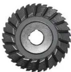
Application Tools and Accessories.
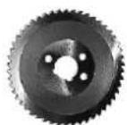
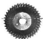
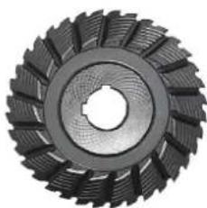
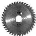
Circular saw blades
1
2
3
| Form 1, HSS, for gear type: | |||||
| A, B - For machining steel pipes | |||||
| ∅ | Width | Weight | Number of teeth | Max. cutting depth | Order number |
| (mm) | (mm) | (kg) | (mm) | ||
| 160 | 4 | 0.5 | 50 | 25 | 6 35 02 022 00 6 |
| 180 | 4 | 0.7 | 60 | 35 | 6 35 02 037 00 8 |
| 200 | 4 | 0.9 | 64 | 45 | 6 35 02 053 00 7 |
| 220 | 4 | 1.3 | 70 | 55 | 6 35 02 041 00 1 |
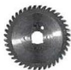
| Form 2, HSS, for gear type: | |||||
| B - For machining cast iron pipes | |||||
| ∅ | Width | Weight | Number of teeth | Max. cutting depth | Order number |
| (mm) | (mm) | (kg) | (mm) | ||
| 160 | 4 | 0.5 | 40 | 25 | 6 35 02 050 00 1 |
| 180 | 4 | 0.7 | 46 | 35 | 6 35 02 098 00 0 |
| 200 | 4 | 0.6 | 50 | 45 | 6 35 02 099 00 4 |
| Form 3, HSS, with tungsten teeth, for gear type: | |||||
| A, B - For machining cast iron pipes (even with cement collar) and unalloyed steel pipes to 400 N/mm ^2 | |||||
| ∅ | W | i | d of teeth | Max. cut- h ting depth | Order nu#ber e |
| (mm) | (mm) | (kg) | (mm) | ||
| 160 4 0.5 | 40 25 6 35 | 02 080 00 | 8 | ||
| 180 4 0.7 | 44 35 6 35 | 02 061 00 | 9 | ||
| 200 4 0.9 | 50 45 6 35 | 02 084 00 | 2 | ||
Feather key
| W x H x L | |
| mm | |
| 6 x 6 x 32 4 02 21 044 00 0 | |
| 8 x 7 x 32 4 02 21 050 00 5 | |
Transport box
| Length x Width x Height | |
| mm | |
| 1000 x 800 x 395 3 39 01 114 00 7 | |
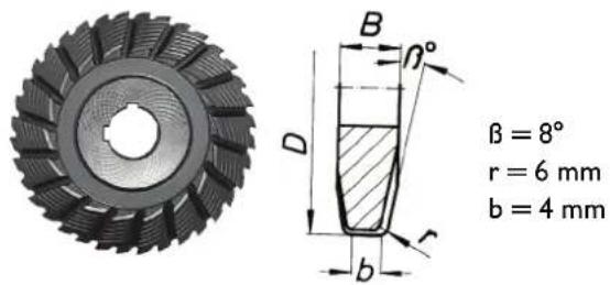
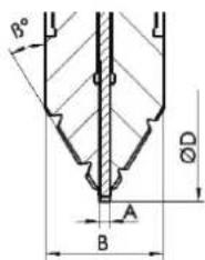
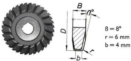
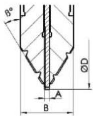
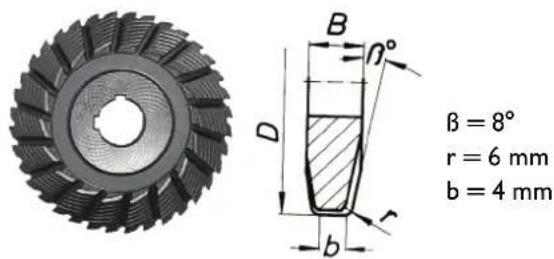
Profile cutter
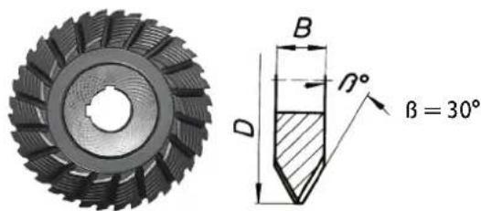
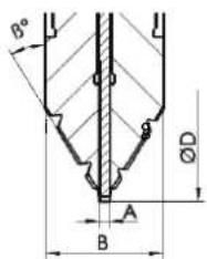
| V-Shape, HSS, for gear type: | ||||||
| A - for machining high-alloy steel pipesB - for machining unalloyed steel and cast iron pipes up to a max. wall thickness of 10 mm and a max. diameter of 1600 mm | ||||||
| D | B | Wt | Member of teeth | βi | Mgating depth | Order number c |
| (mm) | (mm) | (kg) | (°) | In (mm) | ||
| 125 | 25 | 1.6 | 32 | 30 | 25 | 6 35 08 056 00 4 |
| 160 | 30 | 3.2 | 36 | 30 | 25 | 6 35 08 081 00 9 |
| 160 | 30 | 3.3 | 36 | 37.5 | 25 | 6 35 08 093 00 0 |
| 180 | 42 | 5.5 | 36 | 37.5 | 25 | 6 35 08 094 00 0 |
| 180 | 42 | 4.9 | 36 | 30 | 25 | 6 35 08 085 00 8 |
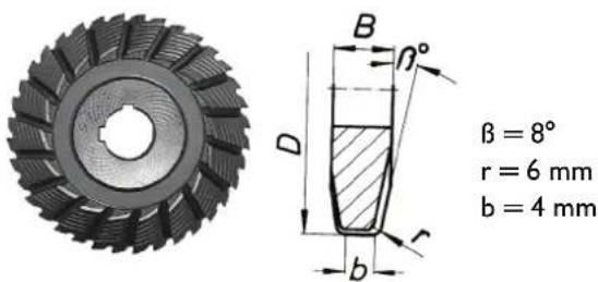
| U-Shape, HSS, for gear type: | |||||
| A - for machining high-alloy steel pipesB - for machining unalloyed steel and cast iron pipes up to a max. wall thickness of 10 mm and a max. diameter of 1600 mm | |||||
| D | B | Weight | Number of teeth | Max. cutting depth | Order number |
| (mm) | (mm) | (kg) | (mm) | ||
| 160 | 25 | 2.8 | 40 | 25 | 6 35 08 089 00 7 |
h t N u m b
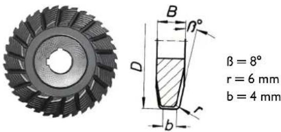
| Gang cutter, HSS, for gear type: | ||||||
| A - for machining high-alloy steel pipesB - for machining unalloyed steel and cast iron pipes up to a max. wall thickness of 10 mm and a max. diameter of 1600 mm | ||||||
| D | B | Wt | Number of teeth | _l | Mag. cutting depth | Order number |
| (mm) | (mm) | (kg) | (°) | (mm) | ||
| 154 | 30.5 | 2.5 | 32 | 30 | 25 | 6 35 08 099 02 0 |
Chain piece
| 10 chain pieces | x 63.5 mm = 635 mm |
| Order number | 3 02 31 013 02 7 |
| 1 chain piece | 31.75 |
| Order number | 3 02 31 029 00 2 |
Spare pin
| Order number | 3 02 17 216 00 4 | Clamping chain 38.5 mm |
| Order number | 3 02 16 166 00 0 | Guide chain 54 mm |
Spare securing ring
| Order number | 3 02 17 216 00 4 |
Spitting wedges made of steel
| Order number | 6 33 05 006 00 8 |
Provided accessories
| Order number | Quantity | Designation |
| 3 39 01 114 00 7 | 1 | Transport box |
| 3 39 01 031 00 1 | 1 | Tool case |
| 3 21 22 007 01 7 | 1 | Hand crank |
| 6 29 01 016 00 2 | 1 | Open-jawed wrench, size 46 mm |
| 6 29 03 010 00 6 | 1 | Open-jawed wrench, size 55 mm |
| 3 12 07 333 01 0 | 1 | Chain tensioner only for RSG Ex 1500 A/B (**) |
| 6 29 11 010 00 0 | 1 | Ring spanner, size 17/19 mm |
| 6 29 06 014 00 0 | 1 | Socket spanner, size 46/41 mm |
| 3 02 31 029 00 2 | 20 | Roller chain |
| 3 02 17 216 00 4 | 20 | Pin |
| 4 26 34 020 00 5 | 40 | Securing ring |
| 6 33 05 013 00 2 | 5 | Splitting wedges, non-sparking for RSG Ex 1500/18 A/B (**) |
| 3 07 02 041 01 4 | 1 | Switchgear assembly for RSG Ex 1500/18 A/B (**) |
| 3 21 74 009 00 1 | 1 | Round sling |
| 3 21 74 010 00 3 | 1 | Round sling |
| 3 07 28 188 00 8 | 1 | CEE coupling for RSG Ex 1500/18 A/B (**) |
| 3 02 31 035 02 0 | 1 | Chain only for RSG Ex 1500 A/B (**) |
| 3 02 16 166 01 0 | 1 | Pin only for RSG Ex 1500 A/B (**) |
| 3 40 56 026 00 0 | 1 | Insertion discs only for RSG Ex 1500 A/B (**) |
Optional accessories
| Order number Quantity Designation | ||
| 3 02 31 013 02 7 1 Chain with 10 chain pieces | ||
| 4 26 34 020 00 5 1 Securing ring | ||
| 3 02 17 216 00 4 1 Pin | ||
| 4 30 12 051 12 2 1 Fitting screw | ||
| 6 33 05 013 00 2 Spark-free drift | ||
| 9 12 01 002 00 4 Compressed-air cooling lubricant supply unit (CCLU) | ||
| 3 24 33 027 01 7 1 Connection parts for CCLU (board) | ||
| 9 26 01 023 02 3 1 Compressor for CCLU | ||
| 3 14 14 055 00 2 1 PA-DL hose, compete, for compressor | ||
| 4 11 36 005 01 9 1 Coupling sleeve | ||
| 3 02 31 035 02 0 1 Chain | ||
| 3 02 16 166 01 0 1 Pin | ||
| 3 40 56 026 00 0 1 Insertion discs | ||
Compressed-air cooling lubricant supply unit 9 12 01 002 00 4
Due to the possible high cutting and feed rates of the pipe milling machine, cooling and lubrication of the tools is required when machining steel. The compressed-air cooling lubricant supply unit operates on the principle of atomisation and evaporation of the cooling lubricant and provides continuous good cooling and lubrication through the spray nozzles mounted on the pipe milling machine.
Additionally, the contamination of soil at the jobsite through otherwise manually applied drilling emulsion, is avoided.
We recommend using BIOCUT 3000 metalworking lubricant as the cooling lubricant. It is a new fully synthetic high-performance lubricant with excellent adhesive and cooling effect, is water-soluble, readily biodegradable and economical in consumption (depending on the setting up to approx. 0.3dm^3/h per nozzle).
BIOCUT 3000 is free of substances that are hazardous to health. It meets the requirements of the German Gas and Water Association. (DVGW).
All ingredients comply with the guidelines of the FDA (Food and Drug Administration) and the German Pharmacopoela (DAB) in the currently valid version.
The lubricating agent is available from:
Lubricating agent BIOCUT 3000 for temperatures to 0°C:
1 L - 3 21 32 039 00 0 5 L - 3 21 32 040 00 0
Cold-resistant lubricating agent for temperatures to -25°C:
1 L - 3 21 32 042 00 0 5 L - 3 21 32 043 00 0
For the three-phase versions RSG Ex ( ^** ), a compressor (FEIN order number 9 26 01 023 02 3) with an intake volume of approx. 130 l/min is required in order to be able to use the compressed-air cooling lubricant supply unit.
Spare parts.
The spare parts list can be found on the Internet under www.fein.com.
Declaration of conformity.
The CE Declaration applies only for European Union and EFTA (European Free Trade Association) countries, and only for products intended for the EU or EFTA market.
FEIN declares itself solely responsible for this product conforming with the relevant provisions given on the last page of this Instruction Manual.
Technical documents at: C. & E. Fein GmbH, D-73529 Schwäbisch Gmünd
Environmental protection, disposal.
Packaging, worn out power tools and accessories should be sorted for environmental-friendly recycling.
natural_image
Pure mechanical assembly diagram showing a bolted joint and shaft (no text or symbols)natural_image
Technical line drawing of a mechanical device with no visible text or symbolsnatural_image
Technical line drawing of a mechanical or electrical component with mounting holes and a central circular dial (no text or symbols)natural_image
Technical line drawing of a mechanical device with no visible text or symbolsnatural_image
Technical line drawing of a mechanical or electrical component with mounting holes and a central circular dial (no text or symbols)natural_image
Close-up of a mechanical gear with visible teeth and central bore (no text or symbols)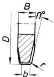
$$ \beta = 8 ^ {\circ} $$
$$ r = 6 \mathrm{mm} $$
$$ b = 4 \mathrm{mm} $$
natural_image
Technical line drawing of a mechanical assembly with no visible text or symbolsnatural_image
Technical line drawing of a mechanical device with no visible text or symbolsnatural_image
Technical line drawing of a mechanical device with mounting holes and a central circular component (no text or symbols)- Motor 2860 rpm 2860 rpm
- Útiles 35 rpm 70 rpm
Avance (f) 40 mm/min 80 mm/min
Potencia nominal (P) 1500 W 1500 W
natural_image
Technical line drawing of a mechanical device with no visible text or symbolsnatural_image
Technical line drawing of a mechanical device with mounting holes and a central circular component (no text or symbols)natural_image
Close-up of a mechanical gear with visible teeth and central bore (no text or symbols)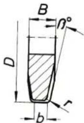
$$ \beta = 8 ^ {\circ} $$
$$ r = 6 \mathrm{mm} $$
$$ b = 4 \mathrm{mm} $$
natural_image
Technical line drawing of a mechanical assembly with no visible text or symbolsnatural_image
Technical line drawing of a mechanical device with no visible text or symbolsnatural_image
Technical line drawing of a mechanical or electrical component with mounting holes and a central dial (no text or symbols)natural_image
Close-up of a mechanical gear with visible teeth and central bore (no text or symbols)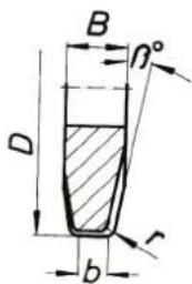
$$ \beta = 8 ^ {\circ} $$
$$ r = 6 \mathrm{mm} $$
$$ b = 4 \mathrm{mm} $$
natural_image
Pure mechanical assembly diagram without any text, numbers, or symbolsnatural_image
Technical line drawing of a mechanical device with no visible text or symbolsnatural_image
Technical line drawing of a mechanical or electrical component with mounting holes and a central dial (no text or symbols)natural_image
Technical line drawing of a mechanical assembly with no visible text or symbolsnatural_image
Technical line drawing of a mechanical device with no visible text or symbolsnatural_image
Technical line drawing of a mechanical or electrical component with mounting holes and a central circular dial (no text or symbols)natural_image
Technical line drawing of a mechanical assembly with no visible text or symbolsnatural_image
Technical line drawing of a mechanical device with no visible text or symbolsnatural_image
Technical line drawing of a mechanical device with mounting holes and internal components (no text or symbols)Smørestoffer for glideflater
| V-form, HSS, for girtype: | ||||||
| A- til bearbeiding av stålrør, høylegertB- til bearbeiding av ulegerte stål- og støpejernsrør opptil en max. veggtykkelse på 10 mm og en max. diameter på 1600 mm | ||||||
| D | B | V | e tenner | R | mt a pedybde | Aeskilingsnummer kt |
| (mm) (mm) (kg) (°) | I | (mm) | ||||
| 125 25 1,6 32 30 25 6 35 08 056 00 4 | ||||||
| 160 30 3,2 36 30 25 6 35 08 081 00 9 | ||||||
| 160 30 3,3 36 37,5 | 25 6 35 08 093 00 0 | |||||
| 180 42 5,5 36 37,5 | 25 6 35 08 094 00 0 | |||||
| 180 42 4,9 36 30 25 6 35 08 085 00 8 | ||||||
Spänning (U) 400 V 400 V
Frekvens (f) 50 Hz 50 Hz
| Nätanslutningstyp | 3 ~ (trefasström) | 3 ~ (trefasström) |
| Tomgångsvarvtal ( n_0 ) | ||
| - Motor | 2860 r/min | 2860 r/min |
| - Insatsverktyg | 35 r/min | 70 r/min |
| Matning (f) | 40 mm/min | 80 mm/min |
| Beräknad effekt (P) | 1500 W | 1500 W |
| Nätsladdens längd (med stickkontakt) | ||
| - RSG Ex 1500 (**) | 2 x 20 m | 2 x 20 m |
| - RSG Ex 18 A/B (**) | 2 x 20 m | 2 x 20 m |
| Skyddsklass | +/-I | +/-I |
| Skyddsklass | IP X4 | IP X4 |
natural_image
Technical line drawing of a mechanical device with no visible text or symbolsnatural_image
Technical line drawing of a mechanical device with mounting holes and central hub (no text or symbols)natural_image
Close-up of a mechanical gear with visible teeth and central bore (no text or symbols)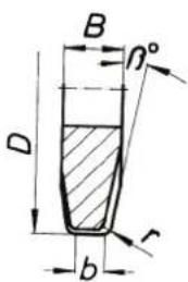
$$ \beta = 8 ^ {\circ} $$
$$ r = 6 \mathrm{mm} $$
$$ b = 4 \mathrm{mm} $$
natural_image
Pure mechanical assembly diagram showing a shaft and housing component without any text or symbolsnatural_image
Technical line drawing of a mechanical device with no visible text or symbolsnatural_image
Technical line drawing of a mechanical device with mounting holes and central hub (no text or symbols)natural_image
Close-up of a mechanical gear or cutting tool with visible teeth and central bore (no text or symbols)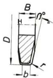
m p a
$$ \beta = 8 ^ {\circ} $$
$$ r = 6 \mathrm{mm} $$
$$ b = 4 \mathrm{mm} $$
natural_image
Technical line drawing of a mechanical assembly with no visible text or symbolsUçların takılması.

Yaralanma tehlikesi
natural_image
Technical line drawing of a mechanical device with no visible text or symbolsnatural_image
Technical line drawing of a mechanical or electrical component with mounting holes and a central circular component (no text or symbols)natural_image
Close-up of a mechanical gear with visible teeth and central bore (no text or symbols)
natural_image
Technical line drawing of a mechanical assembly with no visible text or symbolsnatural_image
Technical line drawing of a mechanical device with no visible text or symbolsnatural_image
Technical line drawing of a mechanical or electrical component with mounting holes and a central dial (no text or symbols)natural_image
Close-up of a mechanical gear with visible teeth and central bore (no text or symbols)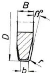
$$ \beta = 8 ^ {\circ} $$
$$ r = 6 \mathrm{mm} $$
$$ b = 4 \mathrm{mm} $$
natural_image
Technical line drawing of a mechanical assembly with no visible text or symbolsnatural_image
Technical line drawing of a mechanical device with no visible text or symbolsnatural_image
Technical line drawing of a mechanical device with mounting flanges and a central rotary knob (no text or symbols)natural_image
Close-up of a mechanical gear or turbine blade with teeth and central bore (no text or symbols visible)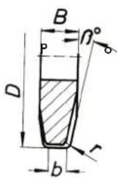
e t
$$ \begin{array}{l} \beta = 8 ^ {\circ} \ r = 6 \mathrm{mm} \ b = 4 \mathrm{mm} \ \end{array} $$
natural_image
Pure mechanical assembly diagram showing a shaft and housing (no text or symbols)natural_image
Technical line drawing of a mechanical device with internal components and a pointed tip (no text or symbols)natural_image
Technical line drawing of a mechanical or electrical component with mounting holes and a central circular dial (no text or symbols)Tvar V, HSS, pre typ prevodovky:
| A – na opracovávanie ocelových rúr, vysoko legovanýchB – na opracovávanie nelegovaných ocelových a liatinových rúr do max. hrúbky steny 10 mm a max. priemeru 1 600 mm | ||||||
| D | B | Hmotn. | Početzubov | β | Max.híbka rezu | Objednávacie číslo |
| (mm) | (mm) | (kg) | (°) | v(mm) | ||
| 125 | 25 | 1,6 | 32 | 30 | 25 | 6 35 08 056 00 4 |
| 160 | 30 | 3,2 | 36 | 30 | 25 | 6 35 08 081 00 9 |
| 160 | 30 | 3,3 | 36 | 37,5 | 25 | 6 35 08 093 00 0 |
| 180 | 42 | 5,5 | 36 | 37,5 | 25 | 6 35 08 094 00 0 |
| 180 | 42 | 4,9 | 36 | 30 | 25 | 6 35 08 085 00 8 |
natural_image
Close-up of a mechanical gear or turbine blade with visible teeth and central bore (no text or symbols)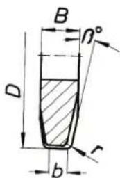
natural_image
Pure mechanical assembly diagram without any text, numbers, or symbolsnatural_image
Technical line drawing of a mechanical device with no visible text or symbolsnatural_image
Technical line drawing of a mechanical or electrical component with mounting holes and a central circular dial (no text or symbols)natural_image
Close-up of a mechanical gear or turbine blade with visible teeth and central bore (no text or symbols)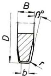
$$ \beta = 8 ^ {\circ} $$
$$ r = 6 \mathrm{mm} $$
$$ b = 4 \mathrm{mm} $$
Tip racord retea 3 \~ (current trifazic) 3 \~ (current trifazic)
natural_image
Pure mechanical assembly diagram showing a shaft and housing component without any text or symbolsnatural_image
Technical line drawing of a mechanical device with no visible text or symbolsnatural_image
Technical line drawing of a mechanical or electrical component with mounting holes and a central dial (no text or symbols)Recipient de transport
natural_image
Close-up of a mechanical gear with visible teeth and central bore (no text or symbols)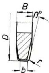
$$ \beta = 8 ^ {\circ} $$
$$ r = 6 \mathrm{mm} $$
$$ b = 4 \mathrm{mm} $$
natural_image
Technical line drawing of a mechanical assembly with no visible text or symbolsnatural_image
Technical line drawing of a mechanical device with no visible text or symbolsnatural_image
Technical line drawing of a mechanical device with mounting holes and central hub (no text or symbols)| Oblika V, HSS, za tip menjalnika: | ||||||
| A - za obdelavo jeklenih cevi, visoko legiranoB - za obdelavo nelegiranih in litih cevi do maks. debeline stene 10 mm in maks. premerom 1600 mm | ||||||
| D | B | Teža | Število zob | Maksimalna globina reza | Šifra blaga | |
| (mm) | (mm) | (kg) | (°) | v (mm) | ||
| 125 | 25 | 1,6 | 32 | 30 | 25 | 6 35 08 056 00 4 |
| 160 | 30 | 3,2 | 36 | 30 | 25 | 6 35 08 081 00 9 |
| 160 | 30 | 3,3 | 36 | 37,5 | 25 | 6 35 08 093 00 0 |
| 180 | 42 | 5,5 | 36 | 37,5 | 25 | 6 35 08 094 00 0 |
| 180 | 42 | 4,9 | 36 | 30 | 25 | 6 35 08 085 00 8 |
| Oblika U, HSS, za tip menjalnika: | |||||
| A - za obdelavo jeklenih cevi, visoko legiranoB - za obdelavo nelegiranih in litih cevi do maks. debeline stene 10 mm in maks. premerom 1600 mm | |||||
| D | B | Teža | Število zob | Maksimalna globina reza | Šifra blaga |
| (mm) (mm) | (kg) | (mm) | |||
| 160 25 | 2,8 | 40 25 | 6 35 08 089 | 00 7 | |
| Rezkalnik z dvema rezkaloma, hitrorezen,za tip menjalnika: | ||||||
| A - za obdelavo jeklenih cevi, visoko legiranoB - za obdelavo nelegiranih in litih cevi do maks. debeline stene 10 mm in maks. premerom 1600 mm | ||||||
| D | B | Teža | Število zob | Maksimalna globina reza | Šifra blaga | |
| (mm) | (mm) | (kg) | (°) | (mm) | ||
| 154 | 30,5 | 2,5 | 32 | 30 | 25 | 6 35 08 099 02 0 |
Kos verige
| 10 kosov verige x 63,5 mm = 635 mm | |
| Šifra blaga 3 02 31 013 02 7 | |
| 1 kos verige 31,75 | |
| Šifra blaga 3 02 31 029 00 2 | |
Nadomestni sornik
| Šifra blaga 3 02 17 216 00 4 Napenjalna veriga 38,5 mm |
| Šifra blaga 3 02 16 166 00 0 Samovodna veriga 54 mm |
natural_image
Technical line drawing of a mechanical assembly with no visible text or symbolsMontiranje radnih alata.

Opasnost od povreda
Postoji opasnost od povreda zbog slučajnog uključivanja. Pre montiranja radnog alata izvucite mrežni utikač.

Opasnost od povreda
Postoji opasnost od posekotina zbog oštrih sečlva radnog alata. Prilikom montiranja i demontiranja radnog alata nosite zaštitne rukavice.

Opasnost od povreda
Postoji opasnost od opeklina zbog vrućeg radnog alata. Prilikom demontiranja radnog alata nosite zaštitne rukavice.
Nosite zaštitne rukavice.
natural_image
Technical line drawing of a mechanical device with no visible text or symbolsMašinama za glodanje cevi sa električnim pogonom spreda priključite kombinaciju sklopnih uređaja sa sljedećim komponentama:
natural_image
Technical line drawing of a mechanical device with mounting holes and a central rotary knob (no text or symbols)Ispred kombinacije sklopnih uređaja upotreblte skloplnu kutiju sa dodatnim prekidačem za uključivanje/isključivanje radi aktiviranja mašine za glodanje cevi u eksplozivnom području zone 2. Skloplnu kutiju treba postaviti tako da je rukovalac može u svakom trenutku dosegnuti.
| V oblik, HSS, za tip prenosnika: | ||||||
| A - za obradu čeličnih cevi, visokolegiraneB - za obradu nelegiranih čeličnih i levanih cevi do maks. debljine zidova od 10 mm i maks. prečnika od 1600 mm | ||||||
| D B Nav. | Broj | zuba | Maks.dubina rezanja | Br. artikla | ||
| (mm) | (mm) | (kg) | (°) | in(mm) | ||
| 125 | 25 | 1,6 | 32 | 30 | 25 | 6 35 08 056 00 4 |
| 160 | 30 | 3,2 | 36 | 30 | 25 | 6 35 08 081 00 9 |
| 160 | 30 | 3,3 | 36 | 37,5 | 25 | 6 35 08 093 00 0 |
| 180 | 42 | 5,5 | 36 | 37,5 | 25 | 6 35 08 094 00 0 |
| 180 | 42 | 4,9 | 36 | 30 | 25 | 6 35 08 085 00 8 |
natural_image
Close-up of a mechanical gear with visible teeth and central bore (no text or symbols)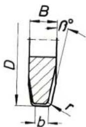
| U oblik, HSS, za tip prenosnika: | |||||
| A - za obradu čeličnih cevi, visokolegiraneB - za obradu nelegiranih čeličnih i levanih cevi do maks. debljine zidova od 10 mm i maks. prečnika od 1600 mm | |||||
| D B | Nav. | Broj zuba | Maks. | dubina rezanja | Br. artikla |
| (mm) | (mm) | (kg) | (mm) | ||
| 160 | 25 | 2,8 | 40 | 25 | 6 35 08 089 00 7 |
| Komplet glodala, HSS, za tip prenosnika: | ||||||
| A - za obradu čeličnih cevi, visokolegiraneB - za obradu nelegiranih čeličnih i levanih cevi do maks. debljine zidova od 10 mm i maks. prečnika od 1600 mm | ||||||
| D B Nav. | Broj | zuba | Maks.dubinarezanja | Br. artikla | ||
| (mm) | (mm) | (kg) | (°) | (mm) | ||
| 154 | 30,5 | 2,5 | 32 | 30 | 25 | 6 35 08 099 02 0 |
Deo Ianca
| 10 delova lanca x 63,5 mm = 635 mm | |
| Br. artikla 3 02 31 013 02 7 | |
| 1 deo lanca 31,75 | |
| Br. artikla 3 02 31 029 00 2 | |
Rezervni šraf
| Br. artikla 3 02 17 21 | 6 00 4 Zatezni lanac 38,5 mm | |
| Br. artikla 3 02 16 16 | 6 00 0 Vodeći lanac 54 mm |
natural_image
Technical line drawing of a mechanical assembly with no visible text or symbolsMontiranje radnih alata.

Opasnost od ozljeda
natural_image
Technical line drawing of a mechanical device with no visible text or symbolsnatural_image
Technical line drawing of a mechanical device with mounting holes and central hub (no text or symbols)| V oblik, HSS, za tip prijenosnika: | ||||||
| A - za obradu čeličnih cijevi, visokolegiraneB - za obradu nelegiranih čeličnih i lijevanih cijevi do maks. debljine zidova od 10 mm i maks. promjera od 1600 mm | ||||||
| D B Nav. | Broj | zuba | M a dubina rezanja | Br. krtikla s . | ||
| (mm) | (mm) | (kg) | (°) | in (mm) | ||
| 125 | 25 | 1,6 | 32 | 30 | 25 | 6 35 08 056 00 4 |
| 160 | 30 | 3,2 | 36 | 30 | 25 | 6 35 08 081 00 9 |
| 160 | 30 | 3,3 | 36 | 37,5 | 25 | 6 35 08 093 00 0 |
| 180 | 42 | 5,5 | 36 | 37,5 | 25 | 6 35 08 094 00 0 |
| 180 | 42 | 4,9 | 36 | 30 | 25 | 6 35 08 085 00 8 |
| U oblik, HSS, za tip prijenosnika: | |||||
| A - za obradu čeličnih cijevi, visokolegiraneB - za obradu nelegiranih čeličnih i lijevanih cijevi do maks. debljine zidova od 10 mm i maks. promjera od 1600 mm | |||||
| D B | Nav. | Broj zuba | Maks. | dubina rezanja | Br. artikla |
| (mm) | (mm) | (kg) | (mm) | ||
| 160 | 25 | 2,8 | 40 | 25 | 6 35 08 089 00 7 |
| Komplet glodala, HSS, za tip prijenosnika: | ||||||
| A - za obradu čeličnih cijevi, visokolegiraneB - za obradu nelegiranih čeličnih i lijevanih cijevi do maks. debljine zidova od 10 mm i maks. promjera od 1600 mm | ||||||
| D B Nav. | Broj | zuba | M a dubina rezanja | Br. krtikla s . | ||
| (mm) | (mm) | (kg) | (°) | (mm) | ||
| 154 | 30,5 | 2,5 | 32 | 30 | 25 | 6 35 08 099 02 0 |
Dio Ianca
| 10 dijelova lanca | x 63,5 mm = 635 mm |
| Br. artikla | 3 02 31 013 02 7 |
| 1 dio lanca | 31,75 |
| Br. artikla | 3 02 31 029 00 2 |
Rezervni svornjak
| Br. artikla | 3 02 17 216 00 4 | Zatezni lanac 38,5 mm |
| Br. artikla | 3 02 16 166 00 0 | Vodeći lanac 54 mm |
natural_image
Pure mechanical assembly diagram without any text, numbers, or symbolsnatural_image
Technical line drawing of a mechanical device with no visible text or symbolsnatural_image
Technical line drawing of a mechanical or electrical component with mounting holes and a central circular dial (no text or symbols)natural_image
Pure mechanical assembly diagram showing a bolted joint and shaft (no text or symbols)natural_image
Technical line drawing of a mechanical device with no visible text or symbolsnatural_image
Technical line drawing of a mechanical or electrical component with mounting holes and a central circular dial (no text or symbols)
natural_image
Close-up of a mechanical gear with visible teeth and central bore (no text or symbols)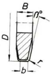
$$ \beta = 8 ^ {\circ} $$
$$ r = 6 \mathrm{mm} $$
$$ b = 4 \mathrm{mm} $$
natural_image
Pure technical line drawing of a mechanical assembly (no text or symbols)natural_image
Technical line drawing of a mechanical device with no visible text or symbolsnatural_image
Technical line drawing of a mechanical device with mounting holes and a central rotary knob (no text or symbols)V-форма, HSS, за редуктор тип:
U-форма, HSS, за редуктор тип:
Üldised ohutusjuhised.
TÄHELEPANU
natural_image
Technical line drawing of a mechanical assembly with no visible text or symbolsnatural_image
Technical line drawing of a mechanical device with no visible text or symbolsnatural_image
Technical line drawing of a mechanical device with mounting holes and central hub (no text or symbols)natural_image
Technical line drawing of a mechanical assembly with no visible text or symbolsnatural_image
Technical line drawing of a mechanical device with no visible text or symbolsnatural_image
Technical line drawing of a mechanical or electrical component with mounting holes and a central circular feature (no text or symbols)natural_image
Pure technical line drawing of a mechanical assembly (no text or symbols)natural_image
Technical line drawing of a mechanical device with no visible text or symbolsnatural_image
Technical line drawing of a mechanical or electrical component with mounting holes and a central circular housing (no text or symbols)natural_image
Close-up of a mechanical gear with visible teeth and central bore (no text or symbols)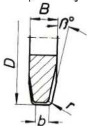
$$ \beta = 8 ^ {\circ} $$
$$ r = 6 \mathrm{mm} $$
$$ b = 4 \mathrm{mm} $$
S v a r s Z o b
natural_image
Pure technical line drawing of a mechanical assembly (no text or symbols)组合安装工具。

有受伤风险
natural_image
Technical line drawing of a mechanical device with no visible text or symbolsnatural_image
Technical line drawing of a mechanical device with mounting holes and a central dial (no text or symbols)China RoHS Status Certificate
中国 RoHS 认证概况
Table of Toxic and Hazardous Substances/Elements and their Content
as required by China's Management Methods for Controlling Pollution by Electronic Information Products
有毒有害物质 / 成分及其含量表
natural_image
Pure mechanical assembly diagram without any text, numbers, or symbols組合安裝工具。

有受傷風險
natural_image
Technical line drawing of a mechanical device with no visible text or symbolsnatural_image
Technical line drawing of a mechanical or electrical component with mounting holes and a central circular feature (no text or symbols)natural_image
Pure technical line drawing of a mechanical assembly (no text or symbols)장착용 액세서리의 조립.

부상 위험
natural_image
Technical line drawing of a mechanical device with no visible text or symbolsnatural_image
Technical line drawing of a mechanical or electrical component with mounting holes and a central circular dial (no text or symbols)| V형태,HSS,기어타입용: | ||||||
| A-스틸파이프가공용,고합금B-최대 벼두께10mm와최대직경1600mm까지의비합금스틸및주철파이프가공용 | ||||||
| D | B | 중량 | 톱니의게수 | β | 최대절단깊이 | 주문번호 |
| (mm) | (mm) | (kg) | (°) | in(mm) | ||
| 125 | 25 | 1.6 | 32 | 30 | 25 | 6 35 08 056 00 4 |
| 160 | 30 | 3.2 | 36 | 30 | 25 | 6 35 08 081 00 9 |
| 160 | 30 | 3.3 | 36 | 37.5 | 25 | 6 35 08 093 00 0 |
| 180 | 42 | 5.5 | 36 | 37.5 | 25 | 6 35 08 094 00 0 |
| 180 | 42 | 4.9 | 36 | 30 | 25 | 6 35 08 085 00 8 |
natural_image
Pure mechanical assembly diagram showing a shaft and housing (no text or symbols)natural_image
Technical line drawing of a mechanical device with no visible text or symbolsnatural_image
Technical line drawing of a mechanical or electrical component with mounting holes and a central circular housing (no text or symbols)natural_image
Pure mechanical assembly diagram showing a shaft and housing (no text or symbols)カッティングツールの取り付け

けがの危険
natural_image
Technical line drawing of a mechanical device with no visible text or symbolsnatural_image
Technical line drawing of a mechanical or electrical component with no visible text or symbolsV 形状、HSS、適用ギアタイプ:
natural_image
Close-up of a mechanical gear with visible teeth and central bore (no text or symbols)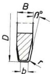
$$ \beta = 8 ^ {\circ} $$
$$ r = 6 \mathrm{mm} $$
$$ b = 4 \mathrm{mm} $$
U 形状、HSS、適用ギアタイプ:
natural_image
Pure mechanical assembly diagram showing a bolt and nut assembly without any text or symbolsnatural_image
Technical line drawing of a mechanical device with no visible text or symbolsnatural_image
Technical line drawing of a mechanical or electrical component with mounting holes and a central circular dial (no text or symbols)natural_image
Close-up of a mechanical gear with visible teeth and central bore (no text or symbols)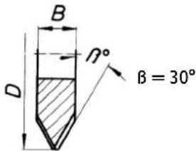
1
2
3
natural_image
Close-up of a mechanical gear with visible teeth and central bore (no text or symbols)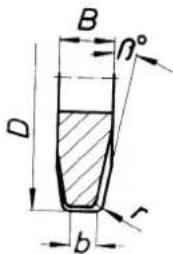
$$ \beta = 8 ^ {\circ} $$
$$ r = 6 \mathrm{mm} $$
$$ b = 4 \mathrm{mm} $$
natural_image
Technical line drawing of a mechanical device with ports and components (no text or symbols)D
natural_image
Technical line drawing of a mechanical device with mounting holes and a central circular component (no text or symbols)الاستخدام.
خطر الإصابة بجروح

natural_image
Pure mechanical assembly diagram showing a shaft and housing (no text or symbols)تركيب عدد الشغل.
خطر الإصابة بجروح
Motor connection diagram
Kopplingsaggregatkombination
3 07 02 041 01 4
辅助开关
3 07 22 024 01 7
輔助開關
3 07 22 024 01 7
추가 스위치
3 07 22 024 01 7
สวิทช์เสริม
3 07 22 024 01 7
追加スイッチ
3 07 22 024 01 7
अतिरिक स्विच
3 07 22 024 01 7
مفتاح إضاني
3 07 22 024 01 7
开关设备装置
3 07 02 041 01 4
開關設備裝置
3 07 02 041 01 4
배진반
3 07 02 041 01 4
ชุดสวิทช์เกียร์
3 07 02 041 01 4
スイッチギアアセンブリ
3 07 02 041 01 4
स्विचगियर असेंबली
3 07 02 041 01 4
تشكيلة أجهزة التحكم
3 07 02 041 01 4
CE
EN ISO 12100:2010
2011/65/EU, 2006/42/EG
U. Hergosell
i. V. S. Böhm i. V. Dr. M. Hergesell
Director of Quality Director of Product
Management Development


- Technical Data.
- Intended Use of the Pipe Milling Machines.
- EC Directive 94/9EC ATEX (Atmosphères Explosibles)
- At a glance.
- For your safety.
- General safety rules.
- WARNING
- Specific safety rules for pipe milling machines.
- Electrically-operated pipe milling machines (design RSG Ex [\*\*]).
- Application.
- Operation (see figure A).
- Transport.
- Before Starting Operation.
- Preliminary work on the pipe to be machined.
- Preliminary work on the pipe milling machine (see figure A).
- Clamping the pipe milling machine on the pipe.
- Mounting the chain links.
- Tensioning the chain links (see figure A).
- Danger of accidents!
- Mounting Application Tools.
- Danger of injury
- Wear protective gloves.
- Starting Operation.
- Pipe milling machine:
- Pipe milling machine in partially explosion-proof design:
- Danger of explosion
- Operation.
- Starting procedure
- Return motion of the pipe milling machines (RSG Ex [\*\*]).
- Possible damage!
- The pipe milling machine is not suitable for making cuts in return motion!
- Notes on cooling and lubrication.
- Observe the manufacturer's information/notes on the coolant being used
- Adjusting the running accuracy.
- Installing additional chain links.
- Clamping the pipe milling machine to a pipe.
- Example:
- Track guidance through guide chain
- Final work after each work assignment.
- Storing the pipe milling machine.
- Maintenance and Repairs.
- On maintenance and repairs.
- General information
- Maintenance of chain links
- Danger of accidents! Before reviving the ck
- Power supply cord
- Feed mechanism (see figure A)
- Disassembly:
- Assembly:
- Tightening device
- Lubricants for sliding surfaces
- Warranty.
- Application Tools and Accessories.
- Compressed-air cooling lubricant supply unit 9 12 01 002 00 4
- Spare parts.
- Declaration of conformity.
- Environmental protection, disposal.
- Smørestoffer for glideflater
- Uçların takılması.
- Yaralanma tehlikesi
- Recipient de transport
- Montiranje radnih alata.
- Opasnost od povreda
- Opasnost od ozljeda
- Üldised ohutusjuhised.
- TÄHELEPANU
- 组合安装工具。
- China RoHS Status Certificate
- 中国 RoHS 认证概况
- 組合安裝工具。
- 장착용 액세서리의 조립.
- 부상 위험
- カッティングツールの取り付け
- けがの危険
Brand : Fein
Model : RSG EX 1500 B
Category : Milling machine