
RDG 1500 B - Milling machine Fein - Free user manual and instructions
Find the device manual for free RDG 1500 B Fein in PDF.

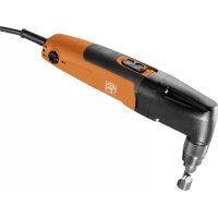
| Product type | Pneumatic tube milling machine |
| Brand / Model | Fein RDG 1500 B |
| Power supply | Compressed air, 6 bar max |
| Air consumption under load | 72 l/s |
| Useful power | 2000 W |
| No-load speed (motor) | 6000 min⁻¹ |
| Cutting tool speed | 70 min⁻¹ |
| Automatic feed | 80 mm/min |
| Max. tool diameter | 220 mm |
| Tube diameter range | 250 - 1500 mm (depending on carrier axle position) |
| Weight | approx. 67 kg |
| Dimensions (L × W × H) | 980 × 450 × 280 mm |
| Sound pressure level | 103 dB(A) |
| Sound intensity level | 116 dB(A) |
| Maintenance | Gear oil change every 80-120 h (first) then 200-250 h; clean pneumatic motor every 200 h |
| Recommended lubricant | ARAL ÖL Degol BMB 460 gear oil (standard) or BMB 100 (low temperature) |
| Included accessories | Transport container, crank, wrenches, chain tensioner, chains, bolts, maintenance unit |
| Warranty | According to applicable legal regulations |
Frequently Asked Questions - RDG 1500 B Fein
User questions about RDG 1500 B Fein
0 question about this device. Answer the ones you know or ask your own.
Ask a new question about this device
Download the instructions for your Milling machine in PDF format for free! Find your manual RDG 1500 B - Fein and take your electronic device back in hand. On this page are published all the documents necessary for the use of your device. RDG 1500 B by Fein.
USER MANUAL RDG 1500 B Fein
34101251050 Tefluf Sow 1 Donszing 25 April 2018 8:21:03

RSG Ex 1500 A (**) 7 160 ... RSG Ex 1500 B (**) 7 160 ... RSG 1500 A (**) 7 160 ... RSG 1500 B (**) 7 160 ... RDG 1500 A (**) 7 160 ... RDG 1500 B (**) 7 345 ...

CE
EN ISO 12100:2010 EN 55014-1:2006 + A1:2009 + A2:2011 EN 55014-2:2015 EN 61000-3-2:2014 EN 61000-3-11:2000 2011/65/EU, 2006/42/EG, 2014/30/EU

FEIN Service
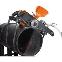
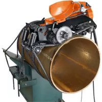
natural_image
Industrial machine with chain tracks and a motor, mounted on a cylindrical pipe (no visible text or symbols)Specifications....18
Intended use of the pipe milling machine....18
At a glance. 18
For your safety....18
Method of functioning (see Fig. A)....20
Before putting into operation. 20
Putting into operation. 21
Handling....21
Maintenance and repairs....23
Troubleshooting (type RSG (**) and RSG Ex (**)).....25
Troubleshooting (type RDG (**) ). 26
Maintenance unit. 26
Guarantee....27
Milling tools and accessories....27
Spare parts 29
France

natural_image
Technical line drawing of a mechanical device with no visible text or symbolsnatural_image
Technical line drawing of a mechanical device with mounting holes and central hub (no text or symbols)Sachbeschädigung!
natural_image
Close-up of a mechanical gear with visible teeth and central bore (no text or symbols)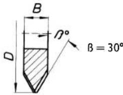
natural_image
Close-up of a mechanical gear with visible teeth and central bore (no text or symbols)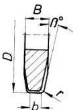
= 8^
r = 6 mm
b = 4 mm
Original Instructions.
Specifications.
Electric pipe milling machine:
Reference number 7 360 ... 7 360 ...
Type* RSG Ex 1500 A (**) RSG Ex 1500 B (**)
Reference number 7 360 ... 7 360
Type RSG 1500 A (**) RSG 1500 B (**)
Voltage (U) 400 V
Frequency (f) 50 Hz
Mains supply 3 \~ (three-phase current)
No-load speed (n0)
Motor 2860 r.p.m.
Rated power (P) 1500 W
Length of the mains cable (with plug)
RSG Ex 1500 A/B (**) 2 x 20 m
RSG 1500 A/B (**) 10 m
Weight (m), approx. 73 kg
Class of protection ⏻/1
Protective type IP X4
Dimensions:
Max. tool ∅ 220 mm
L_max 980 mm
H_max. 340 mm
B_max. 450 mm
B_1 372 mm
B_2 205 mm
L_1 795 mm
*Electromotor and auxiliary switch in explosion-proof design
The A-weighted sound level of the pipe milling machine in the typical case is:
Sound pressure level 92 dB (A); sound power level 105 dB (A).

Wear ear protection
Pneumatic pipe milling machine:
Reference number 7 560 ... 7 560 ...
Type RDG 1500 A (**) RDG 1500 B(**)
Air pressure (p) 6 bar
Air consumption under 72 l/s
load (Q)
No-load speed ( n_0 )
Motor 6000 r.p.m.
Weight (m), approx. 67 kg
Dimensions:
Max. tool ∅ 220 mm
L_max 980 mm
H_max 280 mm
B_max. 450 mm
B1 372 mm
B2 205 mm
L_1 795 mm
The A-weighted sound level of the pipe milling machine in the typical case is:
Sound pressure level 103 dB (A); sound power level 116 dB (A).

Wear ear protection!
Measuring values are determined according to EN 62 841.
Intended use of the pipe milling machine.
The pipe milling machine is intended for cutting free pipe ends and installed pipes sections of sufficient stability, made of steel or cast iron, as well as for chamfering pipe ends prior to welding them at construction sites or in the open. The pipe milling machine is for specialty companies and to be operated by specialists; it is not intended for continuous everyday use.
EU Directive 94/9EU ATEX (Atmosphères Explosibles)
We should like to point out that the Fein pipe milling machines of type RDG ( ^ ) / RSG ( ^ ) / RSG Ex ( ^** ) have not been approved for use in areas where there is risk of explosion and that there are no EC type-approval certificates in accordance with the 94/9EC Directive for these pipe milling machines.
(In the case of pipe milling machine type RSG Ex ( ^** ), where the electromotor and the auxiliary switch are concerned, merely two ATEX-conform components are built in.)
The ATEX Directive is only valid for the EC countries.
At a glance.
1 Clamping unit
2 Fixation screw for side plate
3 Side plate
4 Information labe
5 Bolt
6 Threaded spindle
7 Feed unit
8 Fillister head screw for feed unit
9 Tight-fit screw
10 Running axle
11 Clamping lever
12 Hexagon screw
13 Disc
14 Tensioning axle
15 Nut
16 Tool spindle holder
17 Pipe nut
18 Fixation screw for motor
19 Fish plate
20 Chain wheel
21 Transport shaft
22 Securing ring
23 Pin
24 Screw plug, tool spindle holder
25 Carrying handle
26 Depth scale
27 Knurled nut
28 Feed switching lever
29 Hexagon of chain tensioner
30 Washer of chain tensioner
31 Securing screws of chain tensioner
For your safety.

Before using this pipe milling machine please first read the following and act accordingly:
this Instruction Manual,
the relevant national industrial safety regulations.
This instruction manual should be kept for later use and enclosed with the pipe milling machine, should it be passed on or sold.


General safety instructions.
ATTENTION! Please read all the following instructions. Errors caused by non-adherence to the following instructions can cause an electric shock, burns and/or severe injuries. The following term, "pipe milling machine", relates to the electrically powered and pneumatically powered pipe milling machines.
1. Work place.
a) Keep work area clean, dry and tidy. Untidiness and bad lighting can cause accidents.
b) Secure the working area! When using the pipe milling machine, keep child and other persons at a safe distance away. If your mind is diverted, you might lose control of the pipe milling machine.
2. Electrical safety.
a) The electrical connection must not be changed in any way.
b) Protect the connection cable from heat, oil, sharp edges or moving parts. Connection cables that are damaged or tangled increase the risk of an electric shock.
c) Protect electrical lines from being pinched or squeezed.
d) When operating the machine in damp environments is unavoidable, use a residual current device (RCD). The use of a residual current device (RCD) reduces the risk of electric shock.
3. Safety when handling compressed air.
a) Check the compressed-air supply at regular intervals. Protect the hose from bending, squeezing, heat and sharp edges. Tighten the hose clamps. Make sure that damaged hoses and couplings are repaired immediately. If the air supply is defective, the compressed air hose can suddenly toss around and cause injuries. Dust and chippings flying up in the air can cause eye injuries.
4. Personal safety and safety of others.
a) Pay particular attention, be sure of what you are doing and tackle the work you are going to do with your pipe milling machine in a sensible manner. Do not use the pipe milling machine if you are tired or under the influence of drugs, alcohol or medication. One minute of carelessness whilst using the pipe milling machine can cause serious injuries.
b) Wear personal protective equipment. Depending on the use of the pipe milling machine, wearing protective equipment such as safety goggles (always!), dust mask, non-skid safety shoes, hard hat, protective gloves or hearing protection will reduce personal injuries.
c) Prevent unintentional starting. Make sure that the main switch on the switchgear assembly, the auxiliary switch as well as the ball valve are in the "OFF" position. Set the feed switching lever to the "0" position to switch off the feed motion before connecting the pipe milling machine to the power supply and to the compressed-air supply. Connecting the switched-on pipe milling machine to the power and compressed-air supply invites accidents.
d) Remove the adjusting tools and the wrench before you switch the pipe milling machine on. A tool or wrench that has been left on a rotating part of the pipe milling machine can cause injuries.
e) Do not over-estimate yourself. Do not overreach and avoid an abnormal posture. Make sure you have a firm stance and can keep your balance at all times. In this way you are able to control the pipe milling machine better if anything unexpected happens.
f) Wear suitable clothing. Do not wear any baggy clothes or jewellery. Keep your hair, clothing and gloves away from any moving parts. Loose clothing, jewellery or long hair could get caught in the moving parts.
g) Manual carrying and alignment must always be carried out by two persons.
h) Do not assume a false sense of security and disregard the safety regulations for power tools, even if familiar with the machine through multiple use. Careless action can lead to serious injuries within seconds.
5. Application.
a) Do not overload the pipe milling machine. Use the correct cutting tool for your work. With the correct cutting tool you can work better and more safely.
b) Do not use a pipe milling machine that has a defective switch or ball valve. A pipe milling machine that can no longer be switched on or off is dangerous and must be repaired.
c) Disconnect the power supply before you undertake any adjustments to the machine or change the cutting tools. This precautionary measure prevents the pipe milling machine from starting unintentionally.
d) Do not allow anyone to use the pipe milling machine who is not familiar with it and has not read these instructions. Pipe milling machines are dangerous if they are used by inexperienced persons.
e) Maintain the pipe milling machine at regular intervals. Inspect the pipe milling machine for possible damage as well as for other factors that may interfere with the operation of the pipe milling machine. A faulty pipe milling machine should be repaired before using it. A large number of avoidable accidents are caused by pipe milling machines that have been badly kept.
f) Keep the cutting tools sharp and clean. Cutting tools with sharp cutters that have been carefully looked after are less likely to jam and easier to guide.
g) Use the pipe milling machine, the accessories as well as cutting tools according to the instructions in this manual, whereby the working conditions and the activities to be carried out are to be taken into consideration. The use of pipe milling machines for applications different from those intended could result in hazardous situations.
h) Keep handles and gripping surfaces dry, clean, and free from oil and grease. Slippery handles and gripping surfaces do not allow safe operation and control of the machine in unexpected situations.
6. Service.
a) Have your pipe milling machine repaired only through a qualified repair person and only using original replacement parts. This will ensure that the safety of the machine is maintained.
Special safety instructions for pipe milling machines.
Risk of injury
Transport the pipe milling machine only with two persons or with the use of lifting gear.
The national regulations for the prevention of accidents must be complied with when starting up, using and servicing the pipe milling machine.
The Explosion Protection Guidelines of the Professional and Trade Associations are to be observed at all times!
Ensure that the pipe being cut is firmly supported. Non-observance of this safety instruction can lead to serious injury or death.
7. Electric pipe milling machines (type RSG (\*\*)).
The mains voltage must agree with the voltage specification on the pipe milling machine.
The connection for the pipe milling machine must have a fuse protection of 16 amperes.
Check the mains cable and if applicable, the extension cable at regular intervals!
Only connect the pipe milling machine to the switchgear combination when the main switch is turned OFF.
The switchgear combination must be accessible for the operator at all times.
20
en
8. Pneumatic pipe milling machines (type RDG ( ^** )).
The maximum pressure for the pipe milling machine is 6 bar.
Only connect the pipe milling machine to the compressed-air supply when the ball valve is closed.
Method of functioning (see Fig. A).
The pipe milling machine cuts and machines pipe walls using chip-removing cutting tools. It is clamped onto the outer surface of the pipe using the clamping gear and runs around the pipe with a self-actuating advancement. The tools used are metal circular saw blades and profiling cutters with HSS steel or hard metal cutters, depending on the what the pipe is made of.
The setting for the cutting depth is made using the tool spindle holder (16) that is pivot-mounted in the two side plates (3), and can be adjusted by the threaded spindle (6).
The transport shaft (21) that causes the working advancement via the transporting wheels, is driven by the tool spindle via 2 worm-gear levels.
The feed motion can be switched on or off via the feed switching lever (28).
A slipping coupling protects the advancement gear against overload. The bearing of the tool spindle is of a particularly rigid design. The main gear, lubricated by an oil-bath, for driving the tool spindle consists of a planetary and worm-gear level.
The gear is dimensioned in such a way that no damage is caused if the chain should occasionally come to a halt. All gear shafts run in roller bearings.
The machine frame together with the axles has the task of guiding the clamped-on pipe milling machine on the pipe, and transmitting the forces for cutting and advancing. The alignment to the respective external diameter of the pipe is made by adjusting the running axle (10). The clamping chains are composed of individual, identical chain links that are joined together.
The number of the required chain links, i.e. the length of the clamping chain, depends on the external diameter of the pipe.
Before putting into operation.
Preliminary work on the pipe to be machined.
■ Pipes that are cut in the warehouse must be supported underneath such that the cutting tool does not wedge.
In the case of pipes that have been laid, a distance away from the pit wall of at least 50 cm, measured from the outer side of the pipe, must be given at any place over a length of 1 m.
■ The surface of the pipe must be free from any dirt or earth. Remove any soft protective coating on the surface of the pipe.
■ The cutting tool must be selected according to the pipe material, the required form of machining and the cooling lubricant.
■ Remove the welding seams in the area of the sprockets and chains.
For further information, please contact your coolant/lubricant supplier (also see compressed-air cooling-lubricant device 9 12 01 002 00 4).
(Article number of lubricating agent:
Lubricating agent BIOCUT 1L 3 21 32 039 00 0,
Lubricating agent BIOCUT 5L 3 21 32 040 00 0)
Preliminary work on the pipe milling machine (see Fig. A).
Release clamping lever (11).
Raise the tool spindle holder (16) on the feed unit (7) using the handwheel (in the carrying case).
Remove the fitting screws (9) and the refit the running axle (10) to the current exterior pipe diameter in accordance with Table (4). Mount/tighten the fitting screws (9) again.
Specification plate:
| P | D[mm] [inch] | |
| I 250 - 400 | 9.6 - 15.7 | |
| II 400 - 600 | 15.7 - 23.6 | |
| III 600 - 900 | 23.6 - 35.3 | |
| IV 900 - 1 | 500 35.3 - 58.9 |
P: Position of the running axle
D: Diameter of the pipe
Drive out the clamping fixtures (1) for the clamping chains by turning the sprung chain tensioner such that after placing the pipe milling machine on, sufficient clamping/tensioning distance is available.
Assemble the clamping chains to fit the external diameter of the pipe. Position the pipe milling machine on the pipe and secure it with lifting gear in order to prevent slipping off or shifting.
Assemble guide chain with chain tensioner to match the exterior pipe diameter. Affix the guide chain 10 mm clear aside of the clamping chain, opposite of the cutting tool. The clearance between the guide chain bolt and the clamping chain bolt is 10 mm. Check the clearance three times around the circumference.
Clamping the pipe milling machine onto the pipe.
Mounting the link chains.
Place the link chains (that still have open ends) on both sides of the pipe milling machine, over the pipe.
Raise the pipe milling machine and slide the chain links under the sprockets (13), so that the chain links engage in the sprocket teeth after lowering the pipe milling machine. Place the link chains with their open ends over the chain wheels of the clamping axle (14) and running axle (10). Finally close using the bolt (3 02 17 216 00 4) and secure with the 2 securing rings (4 26 34 020 00 5).
Tensioning the link chains (see Fig. A).
Firstly, lightly snug the chain links against the pipe by turning the two spring tubes (1). For exact alignment, push the pipe milling machine backwards and forwards a few times along the circumference of the pipe.
Tension the link chains by turning the sprung chain tensioners until the pin (23, see Fig. A) juts into the elongated hole of the sprung chain tensioner inside the groove punched in the circumference.
Watch the position of the pin during the cutting process. If the pipe should prove to be out of round, either retention or loosen.
Remove all 4 handles prior to the cutting.

Danger of accidents!
Do not continue to turn the sprung chain tensioner beyond this point!
Assembling the cutting tools.

Risk of injury
- by switching ON unintentionallyn.
- Before assembly, remove the mains plug or the compressed-air hose.
- through objects being thrown off or falling down, such as wedges, tools, the pipe milling machine, the workpiece (pipe),....
- through sharp cutting edges of the cutter
Before assembly, remove the mains plug or the compressed-air hose.
■ Before mounting, clean the tool spindle and also the fitting area and contact surfaces.
■ Mount the cutting tool.
■ Tighten the tool tensioning nut.
en
Putting into operation.
Electric pipe milling machine:
natural_image
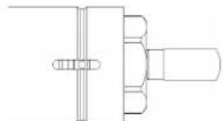
Technical line drawing of a mechanical device with no visible text or symbolsThe pipe milling machines with electric drive have an upstream switchgear combination that contains the following components:
-Main switch/reversing switch
-Motor protection switch
-Undervoltage release
-Plug connections
The main switch is used for switching on and for reversing the direction of rotation.
the undervoltage trip disconnects the pipe milling machine from the mains in order to prevent it from starting again unintentionally.
The motor protection switch and the undervoltage release form one unit. In the case of overload, the motor protection switch switches off; if there is a power cut,
The pipe milling machine is put into operation again by actuating the motor protection switch.
The switchgear combination is to be positioned such that it is accessible for the operator at all times.
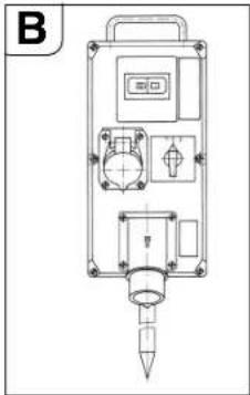
Pipe milling machine partially in explosion-proof design:
natural_image
Technical line drawing of a mechanical device with mounting holes and internal components (no text or symbols)In front of the switchgear combination use a switch box with additional ON/OFF switch for actuating the pipe milling machine in areas in Zone 2 where there is risk of explosion.
The switch box is to be positioned such that it is accessible for the operator at all times.

Danger of explosion
The switchgear combination is to be set up outside Zone 2.
After actuating the automatic circuit breaker, the auxiliary switch must be switched off first prior to switching on again.
Pneumatic pipe milling machine:
The model RDG 1500 A/B (**) is operated by the ball valve mounted on the compressed-air hose; the ball valve is directly in front of the pneumatic motor.
Handling.

Risk of injury
The guard must be completely closed and locked during operation!
Starting Procedure
For pipe milling machines with an electric motor, it is important to ensure that the direction of rotation of the tool is correct. The rotation direction can be reversed with the reversing switch on the switchgear assembly.
■ Shut off the feed via the feed switching lever (28).
■ Switch the pipe milling machine on.
■ Release clamping lever (11) and with the hand crank, pivot the running cutter/saw blade as close as possible to the pipe. Plunging the saw blade deeply into the pipe stabilises the cutting procedure.
■ For milling, choose the slightest possible tool depth. The removal volume increases as the cutting depth increases.
■ Plunge the cutting tool approx. 3 mm deeper than necessary; then return to the necessary depth; the cutting tool is then out of contact.
■ When using the depth scale, allow the cutter/saw blade to slightly graze against the pipe surface. Loosen the knurled nut (27) and set the pointer (28) to 0. Tighten knurled nut (27) again. The feed depth can be read off the scale.
■ Switch off the pipe milling machine.
■ Afterwards, lock the setting by tightening clamping lever (11).
■ Switch the pipe milling machine on again.
■ Switch on the feed via the feed switching lever (28).
■ Provided the motor power is sufficient the pipe wall should be cut in one operation.
■ Pipes that have already been laid can sag during sawing and wedge the cutting tool in the slit. For this reason, the wedges supplied with the machine must be knocked into the slit at regular intervals behind the sawing tool. In areas where there is risk of explosion, use wedges (6 33 05 013 00 2) (RSG Ex 1500 a/b (**) standard accessories) and a hammer made of a non-sparking material.
■ Avoid overloading the pipe milling machine.
■ The machine is overloaded if the motor speed noticeably drops when inserting the running cutting tool. This also results in a decrease in the chip-removal volume.
■ At the same time, this results in a drop of the cutting performance.
■ Affix the workpiece (the pipe being sawn off), to protect it from falling down.
For pipes with a thick wall (s > 10 mm) the welded joint must be milled in several operations.
Congruence in the cutting procedure is influenced by the following factors:
- Alignment of the pipe milling machine at the beginning,
- Geometric deviation of the pipe from the circular or cylindrical form,
- Sharpness of the cutting tools,
- Hardness of the material.
The pipe milling machine is adjusted in such a way that for pipe diameters of 300 mm and 600 mm the beginning and end of the cutting line are approximately in line.
Due to the eccentricity of the guide shaft, the adjustment mark (24, see Fig. D) is only binding for the two given diameters. For larger pipe diameters it may be necessary to make a readjustment.
Reverse run of the pipe milling machines (RSG [\*\*]/RSG Ex [\*\*]).
Avoid damage!
Before the pipe milling machine is reversed, ensure that the cutting tool is retracted, in order to avoid damaging the tool and the gears.
■ Shut off the feed via the feed switching lever (28).
■ Release clamping lever (11)
■ Retract the cutting tool.
■ Turn the main switch/reversing switch to position "0" (OFF).
■ Switch the reversing switch to reverse run.
■ Tighten clamping lever (11).
■ Switch on the feed via the feed switching lever (28).
The pipe milling machine is not suitable for cutting in reverse run! Reverse run is not possible with the pneumatic pipe milling machine!
22
en
Instructions for cooling.
Avoid damage!
We recommend using the FEIN compressed-air cooling lubricator. The chips can wedge if the cooling and lubrication are insufficient. This can cause the tool to break.
Observe the manufacturer's information/notes on the coolant being used
■ Always dry-cut cast iron pipes without using any cooling lubricant.
■ Cool the saw blade or cutter with soapy water whilst cutting plain steel pipes.
Setting the running accuracy.
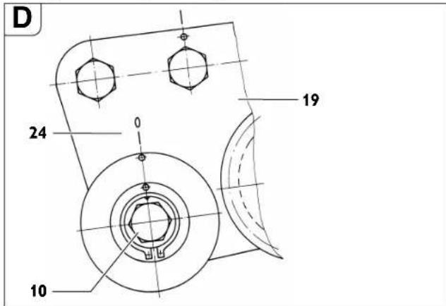
■ Unscrew the nut (15, see Fig A) SW 46.
■ Turn the axle (10) respective to the fish plate (19).
■ Tighten the nut (15).
By turning the axle (10) clockwise (towards the cutting tool), the cutting tool moves rightwards (the viewing direction is the same as the running direction of the pipe milling machine).
When turning the axle anticlockwise, the cutting tool moves leftwards.
Clamping on the pipe milling machine.
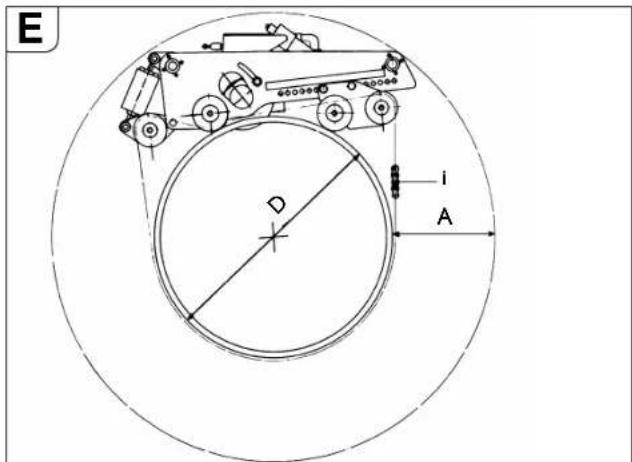
"A" required working space for the deepest cutting depth.
“D” External diameter of the pipe
“i” Number of chain links for pipe diameter “D”.
| Position of the running axle | D A Required chain length for each side [mm] [mm] [mm] [mm] | Total chain length | i* | ||
| 1 250 | 410 | 1427 | 2854 | 5 | |
| 300 | 410 | 1525 | 3050 | 5 | |
| 350 | 410 | 1632 | 3264 | 6 | |
| 400 | 410 | 1744 | 3488 | 6 | |
| 2 400 | 375 | 1800 | 3600 | 6 | |
| 450 | 375 | 1898 | 3796 | 7 | |
| 500 | 375 | 2020 | 4040 | 7 | |
| 550 | 375 | 2147 | 4294 | 7 | |
| 600 | 375 | 2278 | 4556 | 8 | |
| 3 600 | 310 | 2319 | 4638 | 8 | |
| 650 | 310 | 2449 | 4898 | 8 | |
| 700 | 310 | 2582 | 5164 | 9 | |
| 750 | 310 | 2718 | 5436 | 9 | |
| 800 | 310 | 2856 | 5712 | 10 | |
| 850 | 310 | 2996 | 5992 | 10 | |
| 900 | 310 | 3138 | 6276 | 10 | |
| 4 900 | 330 | 3148 | 6296 | 10 | |
| 950 | 330 | 3291 | 6582 | 11 | |
| 1000 | 330 | 3436 | 6872 | 11 | |
| 1050 | 330 | 3581 | 7162 | 12 | |
| 1100 | 330 | 3728 | 7456 | 12 | |
| 1150 | 330 | 3875 | 7750 | 13 | |
| 1200 | 330 | 4023 | 8046 | 13 | |
| 1300 | 330 | 4321 | 8642 | 14 | |
| 1400 | 330 | 4622 | 9244 | 15 | |
| 1500 | 330 | 4924 | 9848 | 16 | |
| *Reference number 3 02 31 013 02 7 consisting of 10 chain links, each 635 mm long. | |||||
To attain optimum chain pre-tensioning, the halved chain links supplied in the carrying case with a length of 31.75 mm can be used, if need be.
Example:
For a pipe diameter of D=400 mm, 6 chain links (reference number 3 02 31 013 02 7) are required.
Track guidance through guide chain
Assemble the length of the guide chain in accordance with the Table.
To achieve optimal chain pre-tension (tolerance of pipe diameter), it is possible to use the half chain-link pieces (with a length of 31.75 mm) provided in the tool box.
| Chain length of guide chain | ||||
| Pipe diameter | Chain length | Chain pieces 635 mm | Chain pieces 63.5 mm | Chain pieces 31.7 mm |
| 250 710 1 1 | 1 | |||
| 300 870 1 4 | 0 | |||
| 350 1030 1 | 6 1 | |||
| 400 1190 1 | 8 1 | |||
| 450 1344 2 | 1 1 | |||
| 500 1500 2 | 4 0 | |||
| 550 1660 2 | 6 1 | |||
| 600 1809 2 | 8 1 | |||
| 650 1970 3 | 1 1 | |||
| 700 2130 3 | 4 0 | |||
| 750 2290 3 | 6 1 | |||
| 800 2440 3 | 8 1 | |||
| 850 2600 4 | 1 1 | |||
| 900 2760 4 | 4 0 | |||
| 950 2921 4 | 6 0 | |||
| 1000 3079 4 | 8 1 | |||
| 1100 3397 5 | 3 1 | |||
| 1200 3714 5 | 8 1 | |||
| 1300 4032 6 | 3 1 | |||
| 1400 4330 6 | 8 1 | |||
| 1500 4640 7 | 3 1 | |||
Order number 3 02 31 034 01 0 (l = 635 mm)
Order number 3 02 31 036 01 0 (l = 63.5 mm)
Order number 3 02 31 035 01 0 (l = 31.7 mm)
Fasten the guide chain to one of both chain pieces on the chain tensioner with the chain bolt and securing ring.
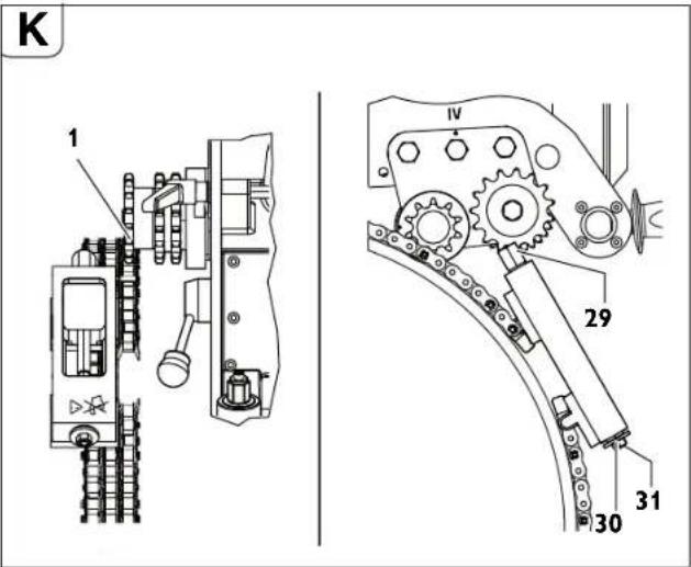
Thread the guide strand of the guide chain through below the two guide-chain sprockets (Fig. K).
Fasten the free end of the guide chain to the chain tensioner with the chain bolt and securing ring.
Snug the guide chain against the pipe by turning the hexagon at the chain tensioner (2).
Align the guide chain with a clearance of 10 mm (bolt of drive chain to bolt of guide chain) and check 3x around the circumference.
Tension the chain tensioner via the hexagon (29) until the washer (30) faces against the housing of the chain tensioner (tensioning range approx. 50 mm). (Max. tightening torque 50 Nm)
Caution! Danger of accidents!
Do not turn or screw the three securing screws (31) on the face side. (see figure K)
Final work after completing each job.
■ Retract the cutting tool
■ Switch off the pipe milling machine
■ Remove the cutting tool
■ Unclamp the pipe milling machine.
For pneumatic machines:
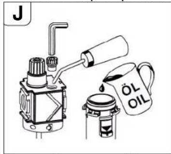
■ After uncoupling the compressed-air hose, pour a little corrosion-preventing oil into the air supply of the pneumatic motor and run it for a short time.
■ Close the hose opening with a protective cap.
Storing the pipe milling machine.
■ Protect the outer metallic parts against corrosion.
■ Store the pipe milling machine in a dry place.
Maintenance and repairs.
Maintenance and repairs.
We recommend our customer service department (central repair). Address at the end of this instruction manual.
Only use original FEIN spare parts.
Risk of injury
by switching ON unintentionallyn.
Before commencing any work on the pipe milling machine, disconnect the mains plug or the compressed-air hose!
General information
Servicing work may only be carried out by qualified engineers.
Care and maintenance work mainly comprises the following:
- Cleaning the outside of the pipe milling machine and the clamping chain
- Visual check of the entire pipe milling machine
- Changing the gear oil
- Filling the compressed-air maintenance unit with lubricant
- Greasing the movement thread and chains
- Greasing the guides of the tool spindle holder in the clamping and transport device.
- Renew the stickers and warning indications on the machine.
Care of the link chains
After removing most of the dirt on the chain with benzine used for cleaning, petroleum or similar agent, clean it carefully moving the chain links.
For guaranteeing sufficient lubrication, leave the chains in viscous oil, e. g. gear oil SAE 140 for several hours.
Danger of accidents!
Before using the chain parts again, make a thorough visual check of the chain links and ensure that they are in perfect condition. Change any damaged parts and replace any missing securing rings.
Tool spindle holder
■ Check the gear-oil level
■ If necessary, change the gear oil.
See also the section on "Lubricants and lubrication plan".
Checking the gear-oil level
Check the oil level and tightness of the tool spindle holder each time before using:
■ Place the pipe milling machine with the side plate opposite the tool protection lying on a horizontal base.
■ Remove the screw plug (25, Fig. A).
Please note:
The oil level is correct if a little gear oil is still just seeping from the tapped hole.
■ If necessary, top up with gear oil (see the section on "Lubricants and lubrication plan").
■ Screw on the screw plug again tightly.
Changing the gear oil
The gear oil is to be changed according to the number of operating hours given in the table, however, at least ever 18 months.
| Gear-oil change intervals [operating hours] | RSG Ex 1500 A (**)RSG 1500 A (**)RDG 1500 A (**) | RSG Ex 1500 B (**)RSG 1500 B (**)RDG 1500 B (**) |
| First oil change after 20 - | 40 80 - 120 | |
| Next oil change after 80 - | 120 200 - 250 |
Our central repairs department carries out the oil change for you and disposes of the used oil.
Drain the gear oil in its warm operating condition immediately after storing the pipe milling machine.
24
en
Pneumatic motor
The pneumatic motor is to be examined and cleaned thoroughly, using clean, oiled compressed air, free from water, after 200 hours of operation, however at least once a year. We therefore recommend our central repairs department for maintenance and repair work on the pneumatic motor.
Avoid damage!
Failure to carry out the stipulated checks can result in considerable damage and a reduction in the performance of the pneumatic motor.
Disassembling the pneumatic motor:
■ Position the pipe milling machine such that the pneumatic motor is at the highest point of the tool spindle holder.
■ Remove the 6 fillister head screws (18) (see Fig. A).
■ Remove the pneumatic motor.
Assemble in the reverse sequence. Care must be taken to connect the motor pinion and planetary gear exactly.
Feed unit (see Fig. A)
- Keep the surface area of the pipe nut (17) free from any dirt and rust formation and always grease slightly.
■ When changing the gear oil, clean the movement thread and grease.
Disassembly:
■ Remove the fillister head screw (8).
■ Pull the bolt (5) out of the cover.
■ Then, using the handwheel unscrew the feed unit from the pipe nut.
■ Clean and grease the threaded parts (see the section on “Lubricants and lubrication plan” on page 24).
■ Change any faulty oil rings.
Assembly:
Assemble in the reverse sequence. Do not damage the oil rings during assembly!
Clamping unit
Avoid dirtying the thread on the eye bolts
(3, Fig. G) in the sprung chain tensioner.
If necessary, clean and grease the thread.
Lubricants and lubrication plan
Lubricants for the pneumatic motor
The pneumatic motor is lubricated via the oiler of the maintenance unit. Merely add a few droplets of oil into the air intake of the pneumatic motor after prolonged downtime.
Lubricating oil for the tool spindle holder
| Lubricant ARAL ÖL Degol | Size of container | Reference number Te | temperature range [°C] | Specification |
| BMB 460 2 | litres 3 | 21 32 009 01 3 -15 | to +50 Gear | oil typeCLPF acc. to DIN 15502 |
| BMB 100 2 | litres 3 | 21 32 009 02 9 -35 | to +5 |
Gear-oil viscosity recommendation for different ambient temperature ranges:
F
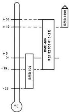
Machines with country code N34 (recognisable by the Order No. on the type plate by digit 9 and 10, which have the numbers 3 and 47360 XX XX 34 X) are delivered with BMB 100.
On delivery, the tool spindle holder is filled with ARAL OIL Degol BMB 460. We urgently request you NOT to use any other gear oil.
Lubricants for gliding surfaces
For lubricating and maintaining the gliding surfaces we recommend acidless, water-resistant branded, friction-bearing grease products.
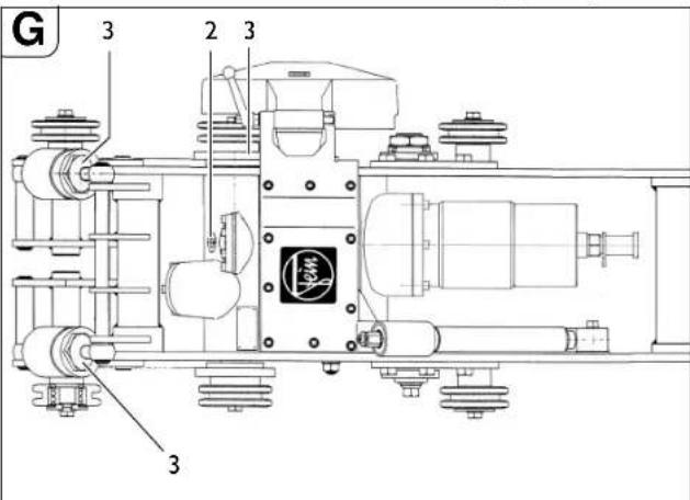
| Lubrication point Lubricant or fuel | |
| 2 (gears) see table: Lubricating oil for tool spindle holder | |
| 3 (gliding surfaces and movement thread) | Friction-bearing grease |
Troubleshooting (type RSG ( ^ ) and RSG Ex ( ^ )).
| Fault Possible causes Measures to be taken | ||
| Motor and cutting tool stop functioning | Very low ambient temperatures Use FEIN gear oil for low temperatures | |
| Blunt cutting tool Change the cutting tool | ||
| No mains voltage Check the mains connection and switching devices | ||
| Incorrect mains voltage Check the data for the mains connection | ||
| Advancement too fast or material removal too high during one revolution | Align the gears and/or reduce the plunging depth | |
| Oil loss in the gear box Replenish oil. If oil loss occurs again, look for leakage point and repair. | ||
| Excessive temperature increase in the motor Reactivate the switchgear combination 3 07 02 041 01 4 | ||
| Defective chain wheel Damaged chain link | Link Change the chain link | |
| Chain incorrectly joined Check the joins and correct | ||
| Chain bolt only partially inserted Fully insert the bolt | ||
| Faulty cutting procedure Pipe milling machine | Machine and chain are not correctly aligned | See Chapter „Preliminary work on the pipe milling machine (see Fig. A).“ auf Page 20 and Abschnitt „Clamping the pipe milling machine onto the pipe.“ auf Page 20 |
| Guide shaft not eccentric Adjust the running accuracy, see Chapter „Setting the running accuracy.“ auf Page 22 | ||
| Blunt cutting tool Change the cutting tool | ||
| Pipe is laid at an incline or vertical, or pipe is out of round | Use the track guiding device, see Chapter „Clamping the pipe milling machine onto the pipe.“ auf Page 20 und Chapter „Track guiding“ auf Page 29 | |
| Cutting tool is overloaded Align the gears and/or reduce the plunging depth | ||
| The function of the machine is reduced or ineffective | No mains voltage Check the mains connection and switching devices | |
| Switch is not on Check switch | ||
| Coupling slips | Align the gears or request the FEIN factory to adjust the pick-up torque of the coupling | |
| Strong vibrations | Advancement too fast | Align gears |
| Cutting tool too deep | Raise the cutting tool | |
| Clamping lever (11) not tightened | Tighten nuts | |
| Chain loose | Check chain tension | |
| Blunt cutting tool Chang the cutting tool | ||
en
Troubleshooting (type RDG ( ^** )).
| Fault Possible causes Measures to be taken | |||
| Motor and cutting tool stop functioning | Ice formation in the pneumatic motor Use | special lubricant | |
| Blunt cutting tool Change the cutting tool | |||
| Fall in pressure Check the compressed-air supply (6 bar) | |||
| Dirt, rust or worn lamellae in the pneumatic motor | Send the motor to the FEIN repairs | ||
| Advancement too fast or material removal too high during one revolution | Align the gears and/or reduce the plunging depth | ||
| Oil loss in the gear box Replenish oil. If oil | loss occurs again, look for leakage point and repair. | ||
| Defective chain wheel Damaged | chain link Change the chain link | ||
| Chain incorrectly joined Check the joins and correct | |||
| Chain bolt only partially inserted Fully insert the bolt | |||
| Faulty cutting procedure Pipe milling machine and chain are not correctly aligned | See Chapter „Preliminary work on the pipe milling machine (see Fig. A).“ auf Page 20 and Abschnitt „Clamping the pipe milling machine onto the pipe.“ auf Page 20 | ||
| Guide shaft not eccentric Adjust the running accuracy, see Chapter „Setting the running accuracy.“ auf Page 22 | |||
| Blunt cutting tool Change the cutting tool | |||
| Pipe is laid at an incline or vertical, or pipe is out of round | Use the track guiding device, see Chapter „Clamping the pipe milling machine onto the pipe.“ auf Page 20 und Chapter „Track guiding“ auf Page 29 | ||
| Cutting tool is overloaded Align the gears and/or reduce the plunging depth | |||
| The function of the machine is reduced or ineffective | Insufficient or no compressed air Check the | compressed-air unit for deficiencies or obstacles | |
| Lamellae are worn Change the lamellae | |||
| Motor is insufficiently lubricated | Check the oil level in the maintenance unit | ||
| Coupling slips | Align the gears or request the FEIN factory to adjust the pick-up torque of the coupling | ||
| Strong vibrations | Advancement too fast | Align gears | |
| Cutting tool too deep | Raise the cutting tool | ||
| Nuts (11) have not been tightened Tighten nuts | |||
| Chain loose | Check chain tension | ||
| Blunt cutting tool Change the cutting tool | |||
Maintenance unit.
for type RDG (\*\*)
The service life of a pneumatic system mainly depends on the processing of the compressed air.
Therefore, filters and line oilers are built into each pneumatic system as maintenance units; however, these have to be operated and serviced correctly.
Installing the maintenance unit
The installation is carried out in the direction of the arrow, a near as possible to the consumer (max. distance away, 10 m).
Filter
The compressed-air filter cleans the compressed air, thereby filtering out the moisture and solid substances. A filter insert is installed of 40 m. Smaller pore sizes can be supplied upon request.
Maintenance
Drain the condensation water regularly via the draining plug.
Cleaning
Release the maintenance unit of pressure and loosen the container from the bayonet lock. Loosen the impingement disc and take out the filter insert; clean the filter insert or replace it by a new one. Screw filter in ensuring O-ring is mounted. Mount container to bayonet lock.
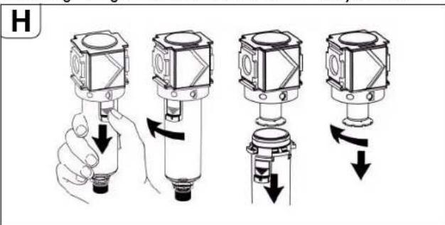
Avoid damage!
Plastic containers (polycarbonate) must only be cleaned with water or benzine used for cleaning purposes.
No liability can be assumed for damage caused due to non-adherence to these instructions.
en
Line oilers
Compressed-air line oilers conduct a thinly oiled mist to the compressed air and thereby create a constant, reliable lubrication for pneumatically powered compressed-air tools.
The built-in air diaphragm adjusts automatically to the air passage. The minimum pressure is 0.5 bar.
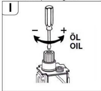
Setting
The oil quantity, measured in drops per minute, can be regulated using the metering screw. To do this, turn the screw in the oiler attachment anti-clockwise, approx. 1 revolution. The drops can be seen in the inspection glass.
Operation
The filling level can be seen on the container. Due to the built-in, pressure-regulating valve, topping up is possible during operation without turning off the compressed air.
- Unscrew the filler plug.
- Fill the container with oil; do not use a funnel.
- Alternatively, dismount the container at the bayonet lock and directly fill in oil. Mount container on again.
- Close the opening again with the filler plug. The oiler is ready for operation.
Max. operating pressure and temperature
For filters and oil-mist lubricators with polycarbonate container, the max. operating pressure is 16 bar to +30 °C max., and 10 bar to +50 °C max.
The following oil types are to be used for the maintenance unit:
■ For light to normal loads, use HLP/ISO-VG22 hydraulic oil with corrosion-protection properties (Order No. 3 21 32 017 05 0 - 0.25 l) or
■ For high loads, use HLP/ISO-VG46 hydraulic oil with corrosion-protection properties (Order No. 3 21 32 006 01 7 - 0.5 l).
■ When not using for longer periods (several months), we recommend using corrosion-protection oils with HD properties (load-carrying capacity level: min. 8) before putting out of operation; e. g. engine-preservation oils „Mobilarma 524“ (Mobil) or „Ensis 10W“ (Shell).
Under unfavourable operating conditions, cold temperatures (below +3 °C) and/or high water content of the compressed air, the motor can ice up. This can be avoided by using a commercially available synthetic de-icing and lubrication agent, e.g. „Kilfrost“, or by using „Renolin SDL 1808“ in conjunction with the metal container of the maintenance unit! Drain the lines and oiler first. Avoid any mixing, as this would reduce or nullify the de-icing effect. The remaining lubrication film does not have to be removed.
■ Kilfrost Anti-icing agent (DEPRAG - Order No. 807287)
■ Kilfrost 400 (Weyer Indutec)
■ Renolin SDL 1808 (Fuchs) is a biologically degradable compressed-air lubricant for restricted use when laying pipes for drinking water! Please generally observe the relevant regulations, legal provisions and the lubricant agent manufacturer's notes.
Flow pressure:
A flow pressure in excess of 6 bar leads to wear. A too low flow pressure leads to performance reductions.
Concerning the compressed-air quality according to ISO 8573-1, we recommend:
Class Residual Oil Residual Dust Residual Water
| [mg/m3]Particle size [μm] | Concen- tration (max.) [mg/m3] | Pres- sure dew point [°C] | Concen- tration (max.) [g/m3] | ||||
| For oiled air | 4 | 5 | 1 | 5 | 8 | + | 3 |
| For unoiled air | 3 | 1 5 5 -20 | 0.88 |
Guarantee.
The guarantee on the product is valid according to the legal regulations in the country where it is marketed.
Milling tools and accessories.
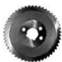
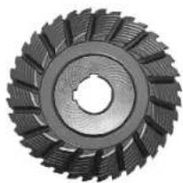
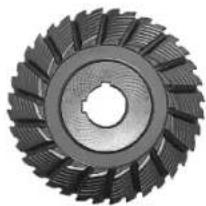
Circular saw blades
1
2
3
Form 1, HSS, for gear type:
a, b - for machining steel pipes
| ∅ Width Weight Number of teeth | Max. cutting depth | Reference number |
[mm] [mm] [kg] [mm]
| 160 | 4 | 0.5 | 50 | 25 | 6 35 02 022 00 6 |
| 180 | 4 | 0.7 | 60 | 35 | 6 35 02 037 00 8 |
| 200 | 4 | 0.9 | 64 | 45 | 6 35 02 053 00 7 |
| 220 | 5 | 1.3 | 70 | 55 | 6 35 02 041 00 1 |
Form 2, HSS, for gear type:
b - for machining cast iron pipes
| ∅ Width Weight Number of teeth | Max. cutting depth | Reference number | |||
| [mm] | [mm] | [kg] | [mm] | ||
| 160 | 4 | 0.5 | 40 | 25 | 6 35 02 050 00 1 |
| 180 | 4 | 0.7 | 46 | 35 | 6 35 02 098 00 0 |
| 200 | 4 | 0.6 | 50 | 45 | 6 35 02 099 00 4 |


28
en
Form 3, HSS, with tungsten teeth, for gear type:
b - For cutting cast iron pipes (even with cement collar) and unalloyed steel pipes to 400 N/mm ^2
∅ Width Weight Number Max. cutting Reference number of teeth depth
[mm] [mm] [kg] [mm]
| 160 4 0.5 | 40 | 25 | 6 35 02 080 00 8 |
| 180 4 0.7 | 44 | 35 | 6 35 02 061 00 9 |
| 200 4 0.9 | 50 | 45 | 6 35 02 084 00 2 |
Adjusting spring
W × H × L (mm)
6×6×3240221044000
8 × 7 × 32 4 02 21 050 00 5
Transport container
Length x Width x Height
mm mm mm
1000 × 800 × 395 3 39 01 114 00 7
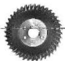
Form cutter
natural_image
Close-up of a mechanical gear with visible teeth and central bore (no text or symbols)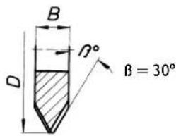
V-form, HSS, for gear type:
a - for machining steel pipes, high-alloyed
b - for machining plain steel pipes and cast iron pipes up to a max. wall thickness of 10 mm and a max. diameter of 1600 mm
| D | B | Weight | Number of teeth | Max. cutting depth | Reference number | |
| [mm] | [mm] | [kg] | [mm] | |||
| 125 | 25 | 1.58 | 32 | 30 | 25 | 6 35 08 056 00 4 |
| 160 | 30 | 3.2 | 36 | 30 | 25 | 6 35 08 081 00 9 |
| 160 | 30 | 3.3 | 36 | 37.5 | 25 | 6 35 08 093 00 0 |
| 180 | 42 | 5.5 | 36 | 37.5 | 25 | 6 35 08 094 00 0 |
| 180 | 42 | 4.9 | 36 | 30 | 25 | 6 35 08 085 00 8 |
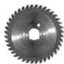
natural_image
Close-up of a mechanical gear with visible teeth and central bore (no text or symbols)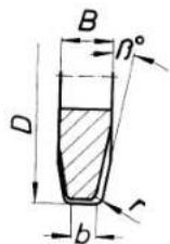
= 8^
r = 6 mm
b = 4 mm
U-form, HSS, for gear type:
a - for machining steel pipes, high-alloyed
b - for machining plain steel pipes and cast iron pipes up to a max. wall thickness of 10 mm and a max. diameter of 1600 mm
| D | B | Weight | Number of teeth | Max. cutting depth | Reference number |
| [mm] | [mm] | [kg] | [mm] | ||
| 160 | 25 | 2.8 | 40 | 25 | 6 35 08 089 00 7 |
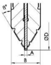
Gang cutters, HSS, for gear type:
a - for machining steel pipes, high-alloyed
b - for machining plain steel pipes and cast iron pipes up to a max. wall thickness of 10 mm and a max. diameter of 1600 mm
| D | B | Weight | Number of teeth | β Max. cutting depth | Reference number |
| [mm] | [mm] | [kg] | [mm] | ||
| 154 | 30.5 | 2.5 | 32 | 30 25 | 6 35 08 099 02 0 |
Special form cutters for other materials and other cutting geometries upon request
Chain link
10 chain links x 63.5 mm = 635 mm
Reference number 3 02 31 013 02 7
1 chain link x 31.75 mm
Reference number 3 02 31 029 00 2
Spare bolt
Reference number 3 02 17 216 00 4
Spare securing ring
Reference number 4 26 34 020 00 5
Spitting wedges made of steel
Reference number 6 33 05 006 00 8
Splitting wedges, non-sparking
Reference number 6 33 05 013 00 2
Standard accessories
| Reference number | Quan- tity | Description |
| 3 39 01 114 00 7 1 | Transport container | |
| 3 39 01 031 00 1 1 | Carrying case | |
| 3 21 22 007 01 7 1 | Handwheel | |
| 6 29 01 016 00 2 1 | Open-jawed wrench, SW 46 | |
| 6 29 03 010 00 6 1 | Open-jawed wrench, SW 55 | |
| 3 12 07 333 01 0 1 | Chain tensioner | |
| 6 29 11 010 00 0 1 | Ring spanner, 17/19 | |
| 6 29 06 013 00 5 1 | Box spanner, SW 46 | |
| 3 02 31 029 00 2 1 | Roller chain | |
| 3 02 17 216 00 4 2 | Bolt | |
| 4 26 34 020 00 5 4 | Securing ring | |
| 6 33 05 006 00 8 1 | Drift only for RSG 1500 A/B (**), RDG 1500 A/B (**) | |
| 6 33 05 013 00 2 5 | Drift, non-sparking only for RSG Ex 1500 A/B (**) | |
| 3 07 02 041 01 4 1 | Switchgear combination only for RSG 1500 A/B (**), RSG Ex 1500 A/B (**) | |
| 3 21 74 009 00 1 1 | Round loop | |
| 3 21 74 010 00 3 1 | Round loop | |
| 3 07 28 188 00 8 1 | CEE coupling for RSG 1500 A/B (**) and RSG Ex 1500 A/B (**) | |
| 3 21 32 006 01 7 1 | Oil can only for RDG 1500 A/B (**) | |
| 3 27 15 129 02 0 1 | Maintenance unit ass. only for RDG 1500 A/B (**) | |
| 3 14 14 001 02 3 1 | Hose ass. only for RDG 1500 A/B (**) | |
| 3 02 31 035 02 0 1 | Chain | |
| 3 02 16 166 01 0 1 | Bolt | |
| 3 40 56 026 00 0 1 | Insertion discs |
Optional accessories
| Reference number | Quantity Description |
| 3 02 31 013 02 7 | Chain with 10 links |
| 4 26 34 020 00 5 | Securing ring |
| 3 02 17 216 00 4 | Bolt |
| 4 30 12 051 12 2 | Tight-fit screw |
| 6 33 05 013 00 2 | Non-sparking drift |
| 3 07 09 022 01 2 | Connection cable (electric) |
| 9 12 01 002 00 4 | Compressed-air cooling-lubricant device (DKSE) |
| 3 24 33 027 01 7 | Connection parts for CCLU (board) |
| 3 27 15 129 02 0 | Maintenance unit ass. only for RDG 1500 A/B (**) |
| 9 26 01 023 02 3 | Compressor for CCLU |
| 3 14 14 055 00 2 | PA-DL hose, complete, for compressor |
| 4 11 36 005 01 9 | Coupling sleeve |
| 3 02 31 035 02 0 | Chain |
| 3 02 16 166 01 0 | Bolt |
| 3 40 56 026 00 0 | Insertion discs |
Compressed-air, cooling-lubricant device 9 12 01 002 00 4
Due to the possible high cutting and advancing speeds of the pipe milling machine, it is necessary to cool and lubricate the tools when machining steel. The compressed-air, cooling-lubricant device function on the principle of finely dispersing and vapourising the cooling lubricant and thereby offers constant, reliable cooling and lubrication through the spray nozzles fitted on the pipe milling machine.
In addition, pollution of the ground at the building site is avoided which is otherwise normally caused by applying the drilling emulsion manually.
As a cooling-lubricant fluid we recommend using the metal-working lubricant, BIOCUT 3000. It is a new kind of fully synthetic, high-performance lubricant; it has an excellent adhesion and cooling effect, is water-soluble, biologically well-decomposable and economical (depending on the setting, up to approx. 0.3dm^3/h per nozzle).
BIOCUT 3000 is free from any substances endangering the health. It fulfils all the requirements of the German association, Deutscher Verein des Gas- und Wasserfachs e. V. (DVGW).
All the contents comply with the Directives of the FDA (Food and Drug Administration) and the Deutsches Arzneibuch (DAB) [German book on medicine] in its currently valid version.
The lubricant can be purchased from the company:
Lubricating agent BIOCUT 3000 for temperatures to 0°C:
1L - 3 21 32 039 00 0
5L - 3 21 32 040 00 0
Cold-resistant lubricating agent for temperatures to -25°C:
1L - 3 21 32 042 00 0
5L - 3 21 32 043 00 0
Fa. Link GmbH
Am Herrenweg 6
D-76228 Karlsruhe
Tel. +49 (0) 721/45 05 55
For the three-phase-current versions RSG ( ^ )/RSG Ex ( ^ ), a compressor is required, i.e. FEIN reference number 9 26 01 023 02 3, with a suction volume of approx. 130 l/min, for enabling the use of the compressed-air, cooling-lubricant device.
Spare parts.
The latest spare parts list can be found on the Internet under www.fein.com.
30
fr
Notice originale.
natural_image
Technical line drawing of a mechanical device with no visible text or symbolsnatural_image
Technical line drawing of a mechanical device with mounting holes and a central circular component (no text or symbols)natural_image
Close-up of a mechanical gear with visible teeth and central bore (no text or symbols)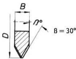
natural_image
Close-up of a mechanical gear with visible teeth and central bore (no text or symbols)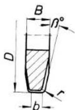
= 8^
r = 6 mm
b = 4 mm
natural_image
Technical line drawing of a mechanical device with internal components and a pointed tip (no text or symbols)natural_image
Technical line drawing of a mechanical device with mounting holes and a central rotary knob (no text or symbols)natural_image
Close-up of a mechanical gear with visible teeth and central bore (no text or symbols)
natural_image
Close-up of a mechanical gear with evenly spaced teeth and central bore (no text or symbols visible)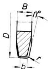
= 8^
r=6 mm
b = 4 mm
natural_image
Technical line drawing of a mechanical device with no visible text or symbolsnatural_image
Technical line drawing of a mechanical device with mounting holes and a central circular component (no text or symbols)¡Daños materiales!
natural_image
Technical line drawing of a mechanical device with no visible text or symbolsnatural_image
Technical line drawing of a mechanical device with mounting holes and a central rotary knob (no text or symbols)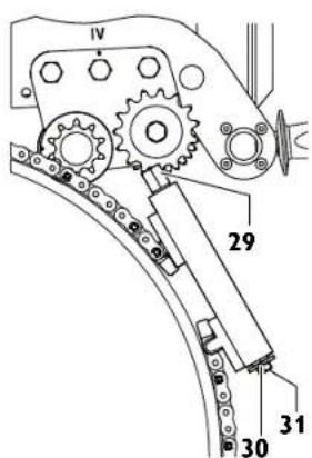
natural_image
Close-up of a mechanical gear with visible teeth and central bore (no text or symbols)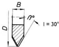
natural_image
Close-up of a mechanical gear with visible teeth and central bore (no text or symbols)
= 8^
r = 6 mm
b = 4 mm
Connection diagram, motor
China RoHS Status Certificate
中国 RoHS 认证概况
Table of Toxic and Hazardous Substances/Elements and their Content
as required by China's Management Methods for Controlling Pollution by Electronic Information Products
有毒有害物质 / 成分及其含量表

- France
- Sachbeschädigung!
- Original Instructions.
- Specifications.
- Electric pipe milling machine:
- Pneumatic pipe milling machine:
- Intended use of the pipe milling machine.
- EU Directive 94/9EU ATEX (Atmosphères Explosibles)
- At a glance.
- For your safety.
- General safety instructions.
- Work place.
- Electrical safety.
- Safety when handling compressed air.
- Personal safety and safety of others.
- Application.
- Service.
- Special safety instructions for pipe milling machines.
- Risk of injury
- Electric pipe milling machines (type RSG (\*\*)).
- en
- Pneumatic pipe milling machines (type RDG ( ** )).
- Method of functioning (see Fig. A).
- Before putting into operation.
- Preliminary work on the pipe to be machined.
- Preliminary work on the pipe milling machine (see Fig. A).
- Clamping the pipe milling machine onto the pipe.
- Mounting the link chains.
- Tensioning the link chains (see Fig. A).
- Danger of accidents!
- Assembling the cutting tools.
- Putting into operation.
- Pipe milling machine partially in explosion-proof design:
- Danger of explosion
- Handling.
- Starting Procedure
- Reverse run of the pipe milling machines (RSG [\*\*]/RSG Ex [\*\*]).
- Avoid damage!
- Instructions for cooling.
- Observe the manufacturer's information/notes on the coolant being used
- Setting the running accuracy.
- Clamping on the pipe milling machine.
- Example:
- Track guidance through guide chain
- Caution! Danger of accidents!
- Final work after completing each job.
- Storing the pipe milling machine.
- Maintenance and repairs.
- General information
- Care of the link chains
- Tool spindle holder
- Checking the gear-oil level
- Please note:
- Changing the gear oil
- Pneumatic motor
- Disassembling the pneumatic motor:
- Feed unit (see Fig. A)
- Disassembly:
- Assembly:
- Clamping unit
- Lubricants and lubrication plan
- Lubricants for the pneumatic motor
- Lubricants for gliding surfaces
- Maintenance unit.
- for type RDG (\*\*)
- Installing the maintenance unit
- Filter
- Maintenance
- Cleaning
- Line oilers
- Setting
- Operation
- Max. operating pressure and temperature
- Flow pressure:
- Guarantee.
- Milling tools and accessories.
- Circular saw blades
- Form 1, HSS, for gear type:
- Form 2, HSS, for gear type:
- Adjusting spring
- Transport container
- Form cutter
- Chain link
- Spare bolt
- Spare securing ring
- Spitting wedges made of steel
- Splitting wedges, non-sparking
- Compressed-air, cooling-lubricant device 9 12 01 002 00 4
- Spare parts.
- fr
- Notice originale.
- ¡Daños materiales!
- China RoHS Status Certificate
- 中国 RoHS 认证概况
Brand : Fein
Model : RDG 1500 B
Category : Milling machine