
Ex18a - Milling machine Fein - Free user manual and instructions
Find the device manual for free Ex18a Fein in PDF.

| Product type | Tube milling machine |
| Brand | Fein |
| Model | Ex18a (RSG Ex 18 A/B) |
| Supply voltage | 400 V, 50 Hz, three-phase |
| Rated power | 1500 W |
| No-load speed (motor) | 2860 rpm |
| Tool speed (depending on version) | 35 rpm (type A) or 70 rpm (type B) |
| Automatic feed | 40 mm/min (type A) or 80 mm/min (type B) |
| Tube diameter range | 250 to 3000 mm (depending on carrier axle position) |
| Power cable length | 2 × 20 m |
| Protection class | I |
| Protection type | IP X4 |
| Machinable materials | Steel, cast iron (including with cement lining) |
| Usable tool types | HSS or carbide circular saw blades, profile cutters |
| Gear lubrication | ARAL Degol BMB 100 or 460 oil (2 liters) |
| Clamping system | Link chains with tensioner |
| Feed | Automatic by worm gear with slip coupling |
| Depth adjustment | By fixed headstock for tool spindle and graduation |
| Transport | By shoulder straps or at least three people |
| Optional accessories | Pneumatic lubrication/refrigeration device, ATEX control box, transport container |
Frequently Asked Questions - Ex18a Fein
User questions about Ex18a Fein
0 question about this device. Answer the ones you know or ask your own.
Ask a new question about this device
Download the instructions for your Milling machine in PDF format for free! Find your manual Ex18a - Fein and take your electronic device back in hand. On this page are published all the documents necessary for the use of your device. Ex18a by Fein.
USER MANUAL Ex18a Fein
Bauart RSG Ex 1500 A () RSG Ex 18 A ()
RSG Ex 1500 B () RSG Ex 18 B (*)
Translation of the Original Instructions.
Symbols, abbreviations and terms used.
| Symbol, character Explanation | |
| 1 ! | Observe the instructions in the text or graphic opposite! |
| 2 | Make sure to read the enclosed documents such as the Instruction Manual and the General Safety Instructions. |
| 3 | Use eye protection during operation. |
| 4 | Use ear protection during operation. |
| 5 | Use protective gloves during operation. |
| 6 | General prohibition sign. This action is prohibited. |
| 7 | Do not reach in! |
| 8 | Do not touch the rotating parts of the power tool. |
| 9 | Do not reach into chains and sprockets! |
| 10 | Warning against sharp edges of application tools, such as the cutting edges of the cutter blades. |
| 11 | Hot surface! |
| 12 | Gripping surface |
| 13 | Additional information. |
| 14 | Confirms the conformity of the power tool with the directives of the European Community. |
| 15 | Worn out power tools and other electrotechnical and electrical products should be sorted separately for environmental-friendly recycling. |
| 16 | Do not turn or screw the three securing screws. |
| 17 | Applies only for China: The duration of environmental protection under normal use of the product is 10 years. |
| (**) May contain numbers and letters | |
Technical Data.
Order number 7360...7360...
Design RSG Ex 1500 A () RSG Ex 1500 B (*)
Order number 7360...7360...
Design* RSG Ex 18 A (^) RSG Ex 18 B (^)
Voltage (U) 400 V 400 V
Frequency (f) 50 Hz 50 Hz
Mains supply: 3 (three-phase current) 3 (three-phase current)
No-load speed (n_0)
-
Motor 2860 rpm 2860 rpm
-
Application tools 35 rpm 70 rpm
Feed (f 40 mm/min 80 mm/min
Rated power (P) 1500 W 1500 W
Power cord length (with plug)
-
RSG Ex 1500 (**) 2 × 20m 2 × 20m
-
RSG Ex 18 A/B (**) 2 × 20m 2 × 20m
Class of protection 1/1
Protection class IP X4 IP X4
*Electric motor and auxiliary switch in explosion-proof design (ATEX-compliant)
Design* RSG Ex 1500 A (**) RSG Ex 18 A (**) RSG Ex 1500 B (**) RSG Ex 18 B (**
| Dimensions: | ||
| - Weight (m) 80 kg | 80 kg | |
| - Max. tool Ø | 220 mm | 220 mm |
| - Lmax. | 974 mm | 1088 mm |
| - Hmax. | 334 mm | 334 mm |
| - Bmax. | 450 mm | 431 mm |
| - B1 | 371 mm | 371 mm |
| - B2 | 201 mm | 201 mm |
| - B3 | 791 mm | 991 mm |
Intended Use of the Pipe Milling Machines.
The pipe milling machine is intended for cutting and milling free pipe ends and installed pipe sections made of steel or cast iron, as well as for chamfering pipe ends prior to welding them at construction sites or in the open. The pipe milling machine is for specialty companies and to be operated by specialists; it is not intended for continuous everyday use.
The complete pipe milling machine is not approved for explosion-protected areas.
The pipe milling machine is not intended for:
- use in areas with explosive atmospheres.
- use during heavy rain and work under water.
- use outside of the temperature range of -20^ to 40^ .
- for cutting explosive materials.
- for cutting combustible material.
EC Directive 94/9EC ATEX (Atmosphères Explosibles)
Please note that FEIN pipe milling machines of the type RSG Ex (^**) are not approved for use in explosive atmospheres and therefore no EC type examination certificates exist for these pipe milling machines in accordance with Directive 94/9EC.
(Only two ATEX-compliant components are installed on the RSG Ex (^**) pipe milling machines, being the electric motor and the auxiliary switch).
The ATEX directive applies only in the EC area.
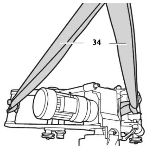
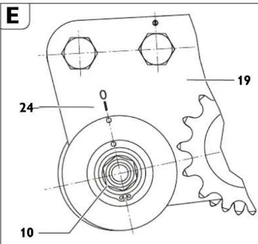
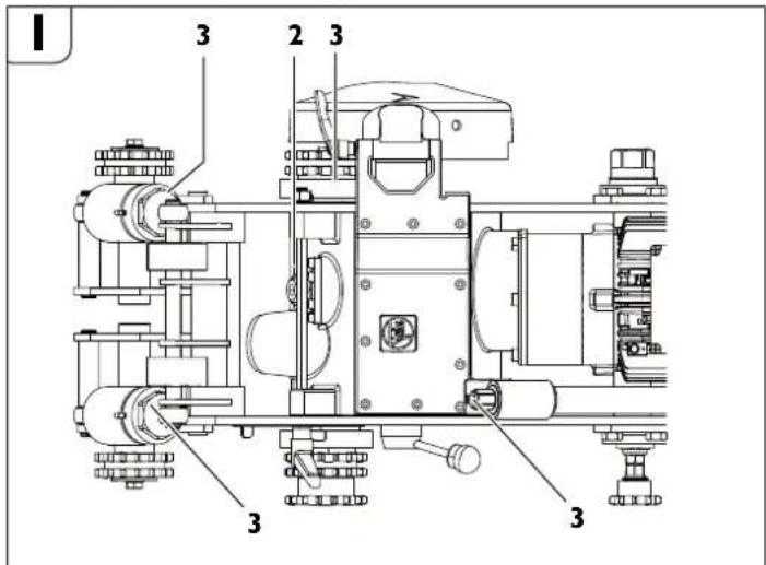
At a glance.
1 Tightening device
2 Fastening screw for side plate
3 Side plate
4 Information label
5 Bolt
6 Threaded spindle
7 Feed mechanism
8 Pan head screw for feed mechanism
9 Fitting screw
10 Running axle
11 Clamping lever
12 Hexagon bolt
13 Washer
14 Tightening axle
15 Nut
16 Tool spindle head
17 Pipe nut
18 Fastening screw for motor
19 Bracket
20 Drive sprocket
21 Transport shaft
22 Securing ring
23 Pin
24 Screw plug of tool spindle head
25 Carrying handle (insulated gripping surfaces)
26 Depth scale
27 Knurled nut
28 Feed switching lever
29 Chain-tensioner hexagon
30 Chain-tensioner disc
31 Securing screws of chain tensioner
32 Securing ring for chain link
33 Bolt of chain link
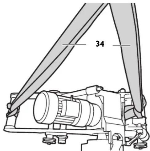
34 Carrying straps
For your safety.
General safety rules.
WARNING Read all safety warnings, instructions, figures and technical data provided with power tool. Failure to follow the warnings
and Instructions may result in electric shock, fire and/or serious injury.
Save all safety warnings and instructions for future reference.
The term "power tool" used in the safety instructions, refers to mains-powered power tools (with mains cable) and to battery-operated power tools (without mains cable).
1) Work area safety
a) Keep work area clean and well lit. Cluttered or dark areas invite accidents.
b) Do not operate power tools in explosive atmospheres, such as in the presence of flammable liquids, gases or dust. Power tools create sparks which may ignite the dust or fumes.
c) Keep children and bystanders away while operating a power tool. Distractions can cause you to lose control.
2) Electrical safety
a) Power tool plugs must match the outlet. Never modify the plug in any way. Do not use any adapter plugs with earthed (grounded) power tools. Unmodified plugs and matching outlets will reduce risk of electric shock.
b) Avoid body contact with earthed or grounded surfaces, such as pipes, radiators, ranges and refrigerators. There is an increased risk of electric shock if your body is earthed or grounded.
c) Do not expose power tools to rain or wet conditions. Water entering a power tool will increase the risk of electric shock.
d) Do not abuse the cord. Never use the cord for carrying, pulling or unplugging the power tool. Keep cord away from heat, oil, sharp edges or moving parts. Damaged or entangled cords increase the risk of electric shock.
e) When operating a power tool outdoors, use an extension cord suitable for outdoor use. Use of a cord suitable for outdoor use reduces the risk of electric shock.
f) If operating a power tool in a damp location is unavoidable, use a residual current device (RCD) protected supply. Use of an RCD reduces the risk of electric shock.
3) Personal safety
a) Stay alert, watch what you are doing and use common sense when operating a power tool. Do not use a power tool while you are tired or under the influence of drugs, alcohol or medication. A moment of inattention while operating power tools may result in serious personal injury.
b) Use personal protective equipment. Always wear eye protection. Protective equipment such as a dust mask, non-skid safety shoes, hard hat or hearing protection used for appropriate conditions will reduce personal injuries.
c) Prevent unintentional starting. Ensure the switch is in the off-position before connecting to power source and/or battery pack, picking up or carrying the tool. Carrying power tools with your finger on the switch or energising power tools that have the switch on invites accidents.
d) Remove any adjusting key or wrench before turning the power tool on. A wrench or a key left attached to a rotating part of the power tool may result in personal injury.
e) Do not overreach. Keep proper footing and balance at all times. This enables better control of the power tool in unexpected situations.
f) Dress properly. Do not wear loose clothing or jewellery. Keep your hair and clothing away from moving parts. Loose clothes, jewellery or long hair can be caught in moving parts.
g) If devices are provided for the connection of dust extraction and collection facilities, ensure these are connected and properly used. Use of dust collection can reduce dust-related hazards.
h) Do not let familiarity gained from frequent use of tools allow you to become complacent and ignore tool safety principles. A careless action can cause severe injury within a fraction of a second.
4) Power tool use and care
a) Do not force the power tool. Use the correct power tool for your application. The correct power tool will do the job better and safer at the rate for which it was designed.
b) Do not use the power tool if the switch does not turn it on and off. Any power tool that cannot be controlled with the switch is dangerous and must be repaired.
c) Disconnect the plug from the power source and/or remove the battery pack, if detachable, from the power tool before making any adjustments, changing accessories, or storing power tools. Such preventive safety measures reduce the risk of starting the power tool accidentally.
d) Store idle power tools out of the reach of children and do not allow persons unfamiliar with the power tool or these instructions to operate the power tool. Power tools are dangerous in the hands of untrained users.
e) Maintain power tools and accessories. Check for misalignment or binding of moving parts, breakage of parts and any other condition that may affect the power tool's operation. If damaged, have the power tool repaired before use. Many accidents are caused by poorly maintained power tools.
f) Keep cutting tools sharp and clean. Properly maintained cutting tools with sharp cutting edges are less likely to bind and are easier to control.
g) Use the power tool, accessories and tool hits etc. in accordance with these instructions, taking into account the working conditions and the work to be performed. Use of the power tool for operations different from those intended could result in a hazardous situation.
h) Keep handles and grasping surfaces dry, clean and free from oil and grease. Slippery handles and grasping surfaces do not allow for safe handling and control of the tool in unexpected situations.
5) Service
a) Have your power tool serviced by a qualified repair person using only identical replacement parts. This will ensure that the safety of the power tool is maintained.
Specific safety rules for pipe milling machines.
Observe the national regulations for prevention of accidents when starting-up, working on and maintaining the pipe milling machine.
Observe the statutory explosion-protection guidelines.
Ensure that the pipe being cut is firmly supported. Non-observance of this safety instruction can lead to serious injury or death.
Electrically-operated pipe milling machines (design RSG Ex \\ ).
The mains voltage and the voltage specification on the pipe milling machine must correspond.
The supply connection of the pipe milling machine must be protected with a 20 A fuse.
Check the power cord and, if necessary, the extension cable regularly!
Connect the pipe milling machine to the switchgear assembly only when the main switch is switched off.
The switchgear assembly must be accessible by the operator at all times.
Application.
Keep handles and gripping surfaces dry, clean, and free from oil and grease. Slippery handles and gripping surfaces do not allow safe operation and control of the machine in unexpected situations.
Hold power tool by insulated gripping surfaces only, because the cutting tool could cut into the machine's power cord. Contact with a "live" wire make exposed metal parts of tool "live" and shock the operator.
Do not overload the pipe milling machine. Use the right application tool for your work. Your work performance will be better and more safe when using the right application tool.
Do not use a pipe milling machine with a defective switch. A pipe milling machine that can no longer be switched on or off is dangerous and must be repaired.
Disconnect the power supply before making machine settings or changing application tools. This safety measure prevents accidental starting of the pipe milling machine.
Do not allow persons unfamiliar with the pipe milling machine or these instructions to operate the machine. Pipe milling machines are dangerous in the hands of untrained users.
Maintain the pipe milling machine at regular intervals. Inspect the pipe milling machine for possible damage as well as for other factors that may interfere with the operation of the pipe milling machine. Repair a pipe milling machine not in proper order before usage. Many preventable accidents are caused by poorly maintained pipe milling machines.
Use the pipe milling machine, the accessories as well as application tools according to the instructions in this manual, whereby the working conditions and the activities to be carried out are to be taken into consideration. The use of pipe milling machines for applications different from those intended could result in hazardous situations.
Operation (see figure A).
The pipe milling machine cuts and mills exposed pipe sections and laid pipes with the use of cutting application tools. It is clamped to the outside of the pipe by its tightening device and moves around the pipe with automatic working feed. The cutting tools used are metal circular saw blades and profile cutters with cutting edges are made of HSS steel or carbide, depending on the pipe material.
- The cutting depth is adjusted by the tool spindle head (16), which is seated in both side plates (3); it can be pivoted, and is adjusted by means of the threaded spindle (6).
The transport shaft (21), which creates the operational feed motion via the transport wheels, is driven by the tool spindle via 2 worm gear stages. - The feed motion can be switched on or off via the feed switching lever (28). A safety clutch protects the feed gearing against overload.
The bearing of the tool spindle is particularly rigid. The oil-bath lubricated main gearbox for driving the tool spindle consists of a planetary and worm gear stage.
The gearing unit is dimensioned in such a manner that occasional seizing of the chain can be endured without damage. All transmission shafts run in anti-friction bearings.
The machine frame with the axles has the task of guiding the clamped pipe milling machine on the pipe and transmitting the cutting and feed forces.
The adaptation to the respective pipe outside diameter is achieved by adjusting the running axle (10).
The tightening chains are sized in length by putting together identical chain segments.
The number of chain segments required, respectively the length of the tightening chains depends on the exterior pipe diameter.
Transport.
B
Danger of injury when transporting the pipe milling machine. Only transport the pipe milling machine using the supplied carrying straps (34) or by at least three persons.
Before Starting Operation.
Danger of injury from unexpected movements of the workpiece. Before processing, secure the workpiece against unexpected movements. When processing the workpiece, there is a risk of unexpected rolling away, falling down or shifting of the workpiece.
The machine may only be operated when in technically proper condition. Each time before starting-up the machine, check it for worn or damaged insert tools and components. Worn or damaged application tools and components must be replaced immediately with new ones.
Preliminary work on the pipe to be machined.
- Underlay/support pipes being cut in the storage area in such a manner that the application tool is not jammed.
For pipes already laid, a clearance of at least 50~cm must be maintained measured from the pipe exterior to the pit wall at every point along a length of 1m - The pipe surface being machined must be free of dirt and soil. Remove soft protective coatings on the machining surface beforehand.
- The cutting tool must be selected according to the pipe material, the required machining shape and cooling lubrication.
- Remove the welding seams in the area of the sprockets and chains.
For more information, please contact your coolant/lubricant supplier. (compressed-air cooling-lubricant device)
Lubricating agent at 0^
Lubricating agent BIOCUT 1L-32132039000
- Lubricating agent BIOCUT 5L - 3 21 32 040 00 0
Lubricating agent up to 25^
Lubricating agent 1L-32132042000
Lubricating agent 5L-32132043000
Preliminary work on the pipe milling machine (see figure A).
- Release clamping lever (11)
- Raise the tool spindle head (16) at the feed mechanism (7) using the hand crank (in tool box).
- Remove the fitting screws (9) and the refit the running axle (10) to the current exterior pipe diameter in accordance with Table (4).
- Mount/tighten the fitting screws (9) again.
RSG Ex 1500 A/B (^**)
| P | D [mm] [inch] | |
| I 250 – 400 9.8 | 15.7 | |
| II 400 – 600 15.7 | - 23.6 | |
| III 600 – 900 23 | 6 – 35.3 | |
| IV 900 – 1500 35 | 5.3 – 58.9 |
RSG Ex 18 A/B (^**)
| P | D [mm] [inch] | |
| I 250 - 400 9.6 | - 15.7 | |
| II 400 - 600 15.7 | - 23.6 | |
| III 600 - 800 23 | 6 - 31.5 | |
| IV 800 - 1000 31 | 1.5 - 39.4 | |
| V 1000 - 1300 39 | 39.4 - 51.2 | |
| VI | 1300 - 3000 51.2 - 118.1 |
P: Position of running axle
D: Pipe diameter
- Extend the tightening devices (1) for the clamping chains by turning the spring tube so that there is sufficient clamping travel after the pipe milling machine has been set down.
Arrange the clamping chains to fit the exterior pipe diameter.
Position the pipe milling machine on the pipe and secure it with lifting gear in order to prevent slipping off or shifting.
Assemble guide chain with chain tensioner to match the exterior pipe diameter. - Affix the guide chain 10mm clear aside of the clamping chain opposite of the milling tool. The clearance from the bolt of the guide chain to the bolt of the clamping chain is 10mm .
- Check the clearance at the circumference at least three times.
Clamping the pipe milling machine on the pipe.
Mounting the chain links.
- On both sides of the pipe milling machine, place the still open chain links over the pipe.
- Raise the pipe milling machine and slide the chain links under the sprockets (20), so that the chain links engage in the sprocket teeth after lowering the pipe milling machine.
- Guide the free ends of the chain links over the sprockets of tightening axle (14) and bracket (19).
- Lock both ends of the chain links with bolt (3 02 17 216 00 4) and secure with the two securing rings (4 26 34 020 00 5).
Tensioning the chain links (see figure A).
- Firstly, lightly snug the chain links against the pipe by turning the two spring tubes (1). For exact alignment, move the pipe milling machine back and forth a few times in the circumferential direction of the pipe.
- Tension the chain links by turning the spring tubes until the pin (23 figure A) in the slotted hole of the spring tube is inside the groove cut in the circumference.
- Observe the position of the pin during the cutting process. If the pipe is out of round, you must either retighten or loosen the tension. Remove all 4 handles prior to the cutting.
Danger of accidents! Do not tension the spring tube beyond this point!
Mounting Application Tools.
Danger of injury
Danger of injury from unintentional switching on. Pull the mains plug before mounting the application tool.
Danger of injury
Danger of cuts from the sharp cutting edges of the application tool. Wear protective gloves when mounting and dismounting the application tool.
Danger of injury
Danger of burns from the hot application tool. Wear protective gloves when dismounting the application tool.
Wear protective gloves.
Only use application tools with cutting edges in proper condition.
- Before bringing the pipe milling machine into contact with the pipe, clean the tool spindle as well as all fitting and contact surfaces.
- Mount the application tool with spacers.
- Firmly tighten the tool clamping nut.
Starting Operation.
Pipe milling machine:
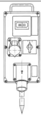
Connect a switchgear assembly on the line side of pipe milling machines with electric drives that have the following components:
-Main switch/reversing switch
Motor protection switch
-Undervoltage release
Plug connectors
The main switch is used as an on switch and for reversing the rotation direction. The motor protection switch and the undervoltage release are a unit. In case of overload, the motor protection switch cuts out; in the event of a mains voltage failure, the undervoltage release disconnects the pipe milling machine from the mains to prevent unintentional restarting.
The pipe milling machine is put back into operation by actuating the motor protection switch.
The switchgear assembly must be positioned so that tor at all times.
Pipe milling machine in partially explosion-proof design:
Upstream of the switchgear assembly, use a switch box with an additional on/off switch to operate the pipe milling machine in Zone 2 hazardous areas. The switch box is positioned so that it can be reached by the operator at all times.
Danger of explosion
The switchgear assembly is to be set up outside of zone 2.
Operation.
Danger of injury
The protection hood must be completely closed and locked during operation!
Danger of injury from chips/swarf being thrown about
These can lead to injuries. Make sure that there are no persons in the danger area.
Danger of fire from chips/swarf being thrown about
Make sure that there are no easily flammable objects in the danger area.
Danger of injury
Danger of injury from parts being thrown about when the pipe milling machine is switched on. Remove the hand crank each time before using the pipe milling machine.
Starting procedure
For pipe milling machines with electric motor, ensure that the rotation direction of the cutting tool is correct. The rotation direction can be reversed with the reversing switch on the switchgear assembly.
Danger of injury
Danger of injury from rotating parts while the machine is running. The danger area of the machine may only be accessed for adjustment work in compliance with the safety-relevant measures.
- Shut off the feed gearing via the feed switching lever (28).
- Switch the pipe milling machine on.
- Release clamping lever (11) and with the hand crank, pivot the running saw blade as deep as possible into the pipe. The deeply immersed saw blade stabilizes the cutting process.
- When milling, select the least possible tool contact. The removal rate increases with increasing cutting depth.
- Immerse application tool approx. 3 mm deeper than necessary, then return to required depth, this disengages the application tool.
- When using the depth scale, allow the application tool to slightly graze against the pipe surface. Loosen the knurled nut (27) and set the pointer (28) to 0. Tighten knurled nut (27) again. The feed depth can be read off the scale.
- Switch the pipe milling machine off.
- Afterwards, lock the setting by tightening clamping lever (11).
-
Switch the pipe milling machine on again.
Switch on the feed gearing via the feed switching lever (28).
If the motor power is sufficient, cut through the pipe wall in one cut. -
Laid pipes can give way during sawing and jam the application tool in the gap. Therefore, the supplied wedges must be driven into the gap behind the saw tool at regular intervals. In hazardous areas, use wedges (6 33 05 013 00 2) (RSG Ex 1500 A/B (^**) supplied accessories) and a hammer made of non-sparking material.
-
Avoid overloading the pipe milling machine.
- An overload is given when the motor speed drops noticeably while the running application tool is plunged in.
- At the same time, this results in a drop of the cutting performance.
- Affix workpiece (cut-off pipe) to protect it from falling down.
For thick-walled pipes (s > 10mm) , the weld joint must be milled in several runs.
The congruent cutting process is influenced by the following factors:
- Alignment of the pipe milling machine when starting,
- Geometric deviation of the pipe from the circular or cylindrical shape,
- Sharpness of the application tool,
Hardness of the material.
The pipe milling machine is adjusted such that for pipe diameters of 300mm and 600mm , the beginning and end of the cutting line approximately coincide.
Due to the eccentricity of the guide shaft, the adjustment mark (24, see Fig. E) is only binding for the two diameters indicated. For larger pipe diameters, readjustment may be necessary.
Return motion of the pipe milling machines (RSG Ex [ ] ).
Possible damage!
Before retracting the pipe milling machine, make sure that the application tool is retracted so that damage to the tool and the gearbox is avoided.
- Shut off the feed gearing via the feed switching lever (28).
- Release clamping fever (11).
- Retract the application tool.
- Set main switch/reversing switch to "0" (off) position.
- Set reversing switch to return motion.
- Tighten clamping lever (11).
Switch on the feed gearing via the feed switching lever (28).
The pipe milling machine is not suitable for making cuts in return motion!
Notes on cooling and lubrication.
Possible damage!
During milling, the application tool must be cooled and lubricated. Insufficient cooling and lubrication can cause chips to jam. This can lead to tool breakage.
Observe the manufacturer's information/notes on the coolant being used
- Always cut gray cast iron pipes dry without cooling lubricant.
Cool the saw blade or cutter with soapy water when cutting unalloyed steel pipes.
Adjusting the running accuracy.
Loosen nut (15, see figure A); wrench size 46.
Turn axle (10) with respect to bracket (19).
Tighten nut (15).
By turning the running axle (10) clockwise (towards the application tool), the application tool will move rightwards (the viewing direction is equal to the movement direction of the pipe milling machine).
When turning the running axle counterclockwise, the application tool will move leftwards.
Installing additional chain links.

Additional chain links may only be installed at the positions intended for this.
Remove the securing ring (32).
- Remove the bolt (33).
Install the desired number of chain links.
Different sizes of chain links are included in the accessories of the machine.
- Insert the bolt (33).
- Mount a new securing ring (32).
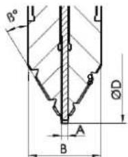
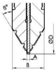
Clamping the pipe milling machine to a pipe.
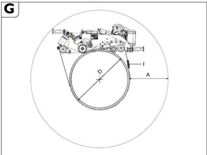
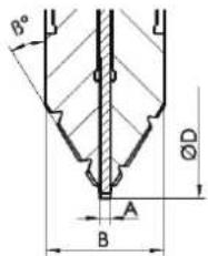
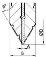
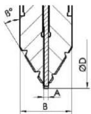
"A" required working space at the greatest cutting depth.
"D" Outer diameter of pipe
"I" Number of chain pieces for pipe diameter "D".
RSG Ex 1500 A/B
| Position of running axle | D [mm] [mm] | A [mm] [mm] | R e length per side | Total qchain length | i# |
| 1 | 250 | 400 | 1427 | 2854 | 5 |
| 300 | 392 | 1525 | 3050 | 5 | |
| 350 | 384 | 1632 | 3264 | 6 | |
| 400 | 378 | 1744 | 3488 | 6 | |
| 2 | 400 | 381 | 1782 | 3564 | 6 |
| 450 | 375 | 1898 | 3796 | 7 | |
| 500 | 369 | 2019 | 4038 | 7 | |
| 550 | 364 | 2144 | 4288 | 7 | |
| 600 | 360 | 2273 | 4546 | 8 | |
| 3 | 600 | 362 | 2302 | 4604 | 8 |
| 650 | 357 | 2433 | 4866 | 8 | |
| 700 | 352 | 2566 | 5132 | 9 | |
| 750 | 348 | 2702 | 5404 | 9 | |
| 800 | 344 | 2840 | 5680 | 10 | |
| 850 | 340 | 2862 | 5724 | 10 | |
| 900 | 337 | 3001 | 6002 | 10 |
| 4 | 900 | 348 | 3142 | 6284 | 10 |
| 950 | 345 | 3284 | 6568 | 11 | |
| 1000 | 342 | 3428 | 6856 | 11 | |
| 1050 | 340 | 3464 | 6928 | 11 | |
| 1100 | 337 | 3607 | 7214 | 12 | |
| 1150 | 335 | 3751 | 7502 | 12 | |
| 1200 | 333 | 3896 | 7792 | 13 | |
| 1300 | 331 | 4062 | 8124 | 13 | |
| 1400 | 329 | 4338 | 8676 | 14 | |
| 1500 | 328 | 4355 | 8710 | 14 | |
| *Order number 3 02 31 013 02 7 consisting of 10 pieces of chain, each 635 mm long. | |||||
RSG Ex 18 A/B
| Position of running axle | D A Required [mm] [mm] | ed chain [mm] [mm] | length per side | Total chain length | i* |
| 1 | 250 | 587 | 1427 | 2854 | 5 |
| 300 | 576 | 1525 | 3050 | 5 | |
| 350 | 564 | 1632 | 3264 | 6 | |
| 400 | 553 | 1744 | 3488 | 6 | |
| 2 | 400 | 522 | 1782 | 3564 | 6 |
| 450 | 511 | 1898 | 3796 | 7 | |
| 500 | 501 | 2019 | 4038 | 7 | |
| 550 | 492 | 2144 | 4288 | 7 | |
| 600 | 483 | 2273 | 4546 | 8 | |
| 3 | 600 | 453 | 2302 | 4604 | 8 |
| 650 | 445 | 2433 | 4866 | 8 | |
| 700 | 437 | 2566 | 5132 | 9 | |
| 750 | 429 | 2702 | 5404 | 9 | |
| 800 | 422 | 2840 | 5680 | 10 | |
| 4 | 800 | 396 | 2862 | 5724 | 10 |
| 850 | 393 | 3001 | 6002 | 10 | |
| 900 | 390 | 3142 | 6284 | 10 | |
| 950 | 386 | 3284 | 6568 | 11 | |
| 1000 | 383 | 3428 | 6856 | 11 | |
| 5 | 1 | 390 | 34640 | 6928 | 11 |
| 1050 | 387 | 3607 | 7214 | 12 | |
| 1100 | 385 | 3751 | 7502 | 12 | |
| 1150 | 382 | 3896 | 7792 | 13 | |
| 1200 | 379 | 4062 | 8124 | 13 | |
| 1300 | 374 | 4338 | 8676 | 14 | |
| 6 | 1 | 383 | 43550 | 8700 | 14 |
| 1400 | 382 | 4651 | 9302 | 15 | |
| 1500 | 378 | 4950 | 9900 | 16 | |
| 1600 | 373 | 5250 | 10500 | 17 | |
| 1700 | 369 | 5553 | 11106 | 18 | |
| 1800 | 366 | 5857 | 11714 | 19 | |
| 1900 | 362 | 6162 | 12324 | 20 | |
| 2000 | 359 | 6468 | 12936 | 21 | |
| 2100 | 356 | 6775 | 13550 | 22 | |
| 2200 | 353 | 7083 | 14166 | 23 | |
| 2300 | 350 | 7391 | 14782 | 24 | |
| 2400 | 348 | 7700 | 15400 | 25 | |
| 2500 e | 346 d | 8009 c | 16018 a | 26 | |
| 2600 | 343 | 8319 | 16638 | 27 | |
| 2700 | 341 | 8629 | 17258 | 28 | |
| 2800 | 339 | 8940 | 17880 | 29 | |
| 2900 | 337 | 9251 | 18502 | 30 | |
| 3000 | 335 | 9562 | 19124 | 31 | |
| *Order number 3 02 31 013 02 7 consisting of 10 pieces of chain, each 635 mm long. | |||||
To achieve optimal chain pre-tension, you may want to use the 31.75mm half chain pieces included in the tool kit.
Example:
For a pipe diameter of D = 400mm 6 chain pieces order number 3 02 31 013 02 7 are required.
Track guidance through guide chain

Assemble the length of the guide chain in accordance with the Table.
To achieve optimal chain pre-tension, you may want to use the 31.75mm half chain pieces included in the tool kit.
Chain length of guide chain
| Pipe diameter | Chain length | Chain pieces | ||
| [mm] | [mm] | mm | 63.5 | mm |
| 250 710 1 1 | 1 | |||
| 300 870 1 4 | 0 | |||
| 350 1030 1 | 6 1 | |||
| 400 1190 1 | 9 0 | |||
| 450 1344 2 | 1 1 | |||
| 500 1500 2 | 4 0 | |||
| 550 1660 2 | 6 1 | |||
| 600 1809 2 | 8 1 | |||
| 650 1970 3 | 1 1 | |||
| 700 2130 3 | 4 0 | |||
| 750 2290 3 | 6 1 | |||
| 800 2440 3 | 8 1 | |||
| 850 2600 4 | 1 0 | |||
| 900 2760 4 | 4 0 | |||
| 950 2921 4 | 6 0 | |||
| 1000 3079 | 4 8 1 | |||
| 1100 3397 | 5 3 1 | |||
| 1200 3714 | 5 8 1 | |||
| 1300 4032 | 6 3 1 | |||
| 1 4 | 0 | 0 4 | 3 3 | 0 6 |
| 1 5 | 0 | 0 4 | 6 4 | 0 7 |
Order number 3 02 31 034 01 0 (l = 635 mm)
Order number 30231036010 (l = 63.5mm)
Order number 30231035010(1=31.7mm)
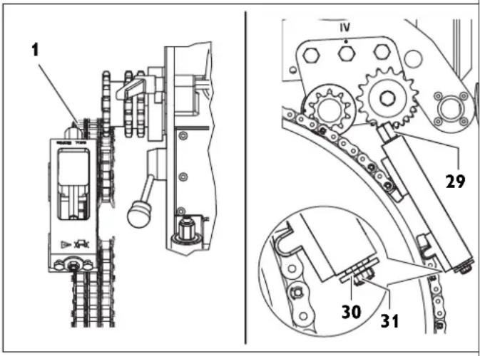
- Fasten the guide chain to one of both chain pieces on the chain tensioner with chain bolt and securing ring.
- Thread the guide strand of the guide chain through below the two guide-chain sprockets (Fig. H).
- Fasten the free end of the guide chain to the chain tensioner with chain bolt and securing ring.
- Snug the guide chain against the pipe by turning the hexagon at the chain tensioner (2).
- Align the guide chain with a clearance of 10mm (bolt of drive chain to bolt of guide chain) and check three times around the circumference.
Tension the chain tensioner via the hexagon (29) until the washer (30) faces against the housing of the chain tensioner (tensioning range approx. 50mm ). (Max. tightening torque 50Nm )
Caution! Danger of accidents! Do not turn or screw the three securing screws (31) on the face side. (see figure H)
Final work after each work assignment.
- Retract the application tool.
- Switch the pipe milling machine off.
- Remove the application tool.
- Dismount pipe milling machine from pipe.
Storing the pipe milling machine.
- Protect the external metal parts against corrosion.
- Store pipe milling machine at a dry location.
Maintenance and Repairs.
On maintenance and repairs.
For FEIN power tools and accessories in need of repair, please contact your FEIN after-sales service. The address can be found on the Internet under www.fein.com.
The current spares parts list for this power tool can be found on our website at www.fein.com.
Use only original spare parts.
If required, you can change the following parts yourself: Application tools, handles, chain, chain links
The machine may only be operated when in technically proper condition. Worn or damaged application tools and components must be replaced immediately with new ones.
Danger of injury
through unintentional switching on.
Before any work on the pipe milling machine, pull the mains plug!
General information
n Maintenance work may only be carried out by trained specialists.
The servicing and maintenance work basically include:
- Exterior cleaning of the pipe milling machine and clamping chains.
- Visual checking of the complete pipe milling machine.
- Changing the gearbox oil.
- Greasing the moving threads and chains.
- Greasing the guides of the tool spindle head in the clamping and transport device.
- Renewing the stickers and warning indications on the machine.
Maintenance of chain links
After removing coarse debris, carefully clean the link chains with benzine, kerosene or similar while moving the chain links.
To ensure lubrication, place the chains afterwards in viscous oil, e.g. SAE 140 gear oil, for several hours.
Danger of accidents!
Before reusing the chain links, carry out a thorough visual inspection to ensure that they are in proper condition. Replace damaged parts and missing securing rings.
Power supply cord
When the machine's power supply cord is damaged, it must be replaced by the manufacturer or their representative.
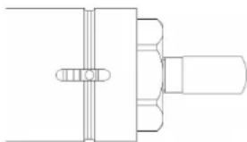
Feed mechanism (see figure A)
- Keep surface area of pipe nut (17) free from debris and any rust; always apply a light coat of grease.
- When changing gearbox oil, clean and grease moving threads.
Disassembly:
- Remove pan head screw (8).
Pull bolt (5) out of lid. - Afterwards, screw feed mechanism out of pipe nut using hand crank.
Clean and grease the threaded parts (see section Lubricants and lubrication chart on page 19). - Replace damaged scraper rings.
Assembly:
Assembly is carried out in reverse order. Do not damage scraper rings when assembling!
Tightening device
Avoid contamination of the threads on the eyebolts (3, Fig. 1) in the spring tube.
Clean and grease threads as required.
Lubricants and lubrication chart
| Lubricating agent ARAL oil Degol | Filling quantity Temperture range [°C] | Specification |
| BMB 460 2 liters 0 to +60 Gear oil, type | CLPF acc. to DIN15502 | |
| BMB 100 2 liters -20 to +40 |
Upon delivery, the tool spindle head is filled with ARAL oil Degol BMB 100. We must strongly advise against the use of any other gear oil.
Lubricants for sliding surfaces
For lubrication and servicing of sliding surfaces, we recommend using plain, acid-free, watertight, brand plain bearing greases.
| Lubricating point Lubricant or operating | material |
| 2 (gearbox) See Table: Lubricating oil ford tool spin-dle head | |
| 3 (sliding surfaces and moving threads) Plain bearing grease | |
Troubleshooting (Design RSG Ex (^**)
| Malfunction Possible Cause Corrective Action | ||
| Motor and application tool fail | Very low ambient temperatures | Use FEIN gear oil for low temperatures |
| Blunt or dull application tool Replace application tool | ||
| No mains voltage Check mains supply and switchgear | ||
| Incorrect mains voltage Check mains supply data | ||
| Feed rate too fast or too high material removal during one run | Adapt gearing and/or reduce immersion depth | |
| Oil loss at gearbox Locate leakage and correct cause - Refill oil | ||
| Excessive temperature increase in motor Reactivate switchgear assembly 3 07 02 041 01 4 | ||
| Defective drive sprocket Damaged chain piece | Replace chain piece | |
| Chain incorrectly connected | Check connection points and correct | |
| Chain pin only partially inserted Fully insert chain pin | ||
| Faulty cutting process | Incorrect alignment of pipe milling machine and chain | see section "Preliminary work on the pipe milling machine (see Fig. A)." on page 16 and section "Clamping the pipe milling machine on the pipe." on page 16 |
| Guide shaft not eccentric | Readjust the running accuracy, see section "Adjusting the running accuracy". on page 17 | |
| Blunt or dull application tool Replace application tool | ||
| Inclined or vertically seated pipe or pipe out of round | Use track guidance device, see section "Clamping the pipe milling machine on the pipe." on page 16 and section "Track guidance" on page 19 | |
| Application tool overloaded | Adapt gearing and/or reduce immersion depth | |
| Reduced or ineffective machine function | No mains voltage | Check mains supply and switchgear |
| Switch not switched on | Check switch | |
| Clutch slips | Adjust gearing or have the response torque of the clutch adjusted at the FEIN factory. | |
| Heavy vibrations | Feed rate too fast | Adjust gearing |
| Application tool immersed too deep | Retract application tool setting | |
| Clamping lever (11) not tightened | Tighten clamping lever | |
| Chain loose | Check chain tension | |
| Blunt or dull application tool Replace application tool |
Warranty.
The warranty for the product is valid in accordance with the legal regulations in the country where it is marketed.
Application Tools and Accessories.
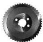
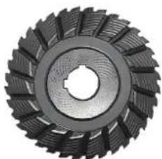
Circular saw blades
1
2
3
| Form 1, HSS, for gear type: | |||||
| A, B - For machining steel pipes | |||||
| ∅ | Width | Weight | Number of teeth | Max. cutting depth | Order number |
| (mm) | (mm) | (kg) | (mm) | ||
| 160 | 4 | 0.5 | 50 | 25 | 6 35 02 022 00 6 |
| 180 | 4 | 0.7 | 60 | 35 | 6 35 02 037 00 8 |
| 200 | 4 | 0.9 | 64 | 45 | 6 35 02 053 00 7 |
| 220 | 4 | 1.3 | 70 | 55 | 6 35 02 041 00 1 |
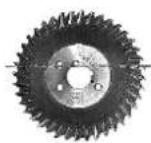
| Form 2, HSS, for gear type: | |||||
| B - For machining cast iron pipes | |||||
| ∅ | Width | Weight | Number of teeth | Max. cutting depth | Order number |
| (mm) | (mm) | (kg) | (mm) | ||
| 160 | 4 | 0.5 | 40 | 25 | 6 35 02 050 00 1 |
| 180 | 4 | 0.7 | 46 | 35 | 6 35 02 098 00 0 |
| 200 | 4 | 0.6 | 50 | 45 | 6 35 02 099 00 4 |
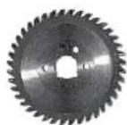
Form 3, HSS, with tungsten teeth, for gear type:
A, B - For machining cast iron pipes (even with cement collar) and unalloyed steel pipes to 400N / mm^2
| ∅ | W | i | d of teeth | Max. cut- ting depth | Order number |
| (mm) | (mm) | (kg) | (mm) | ||
| 160 4 0.5 | 40 25 6 35 | 02 080 00 | 8 | ||
| 180 4 0.7 | 44 35 6 35 | 02 061 00 | 9 | ||
| 200 4 0.9 | 50 45 6 35 | 02 084 00 | 2 |
Feather key
| W x H x L | |
| mm | |
| 6 x 6 x 32 4 02 21 044 00 0 | |
| 8 x 7 x 32 4 02 21 050 00 5 | |
Transport box
| Length x Width x Height | |
| mm | |
| 1000 x 800 x 395 3 39 01 114 00 7 | |
Profile cutter
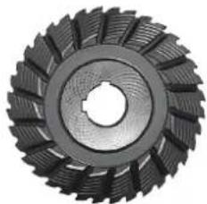
V-Shape, HSS, for gear type:
A - for machining high-alloy steel pipes
B - for machining unalloyed steel and cast iron pipes up to a max. wall thickness of 10 mm and a max. diameter of 1600 mm
| D | B | Wt | Member of teeth | Bi | M g a ting depth | Order number |
| (mm) | (mm) | (kg) | (°) | In (mm) | ||
| 125 | 25 | 1.6 | 32 | 30 | 25 | 6 35 08 056 00 4 |
| 160 | 30 | 3.2 | 36 | 30 | 25 | 6 35 08 081 00 9 |
| 160 | 30 | 3.3 | 36 | 37.5 | 25 | 6 35 08 093 00 0 |
| 180 | 42 | 5.5 | 36 | 37.5 | 25 | 6 35 08 094 00 0 |
| 180 | 42 | 4.9 | 36 | 30 | 25 | 6 35 08 085 00 8 |
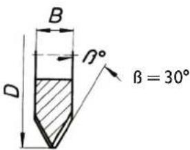
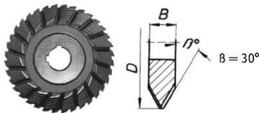
$$ \beta = 8 ^ {\circ} $$
$$ r = 6 \mathrm {m m} $$
$$ b = 4 \mathrm {m m} $$
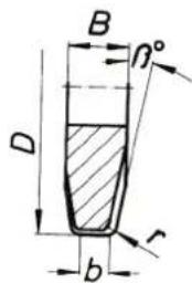
U-Shape, HSS, for gear type:
A - for machining high-alloy steel pipes
B - for machining unalloyed steel and cast iron pipes up to a max. wall thickness of 10 mm and a max. diameter of 1600 mm
| D | B | Weight | Number of teeth | Max. cut- ting depth | Order number |
| (mm) | (mm) | (kg) | (mm) | ||
| 160 | 25 | 2.8 | 40 | 25 | 6 35 08 089 00 7 |
h t N u m b
| Gang cutter, HSS, for gear type: | ||||||
| A - for machining high-alloy steel pipesB - for machining unalloyed steel and cast iron pipes up to a max. wall thickness of 10 mm and a max. diameter of 1600 mm | ||||||
| D | B | Wt | Number of teeth | Bi | Mag. cutting depth | Order number |
| (mm) | (mm) | (kg) | (°) | (mm) | ||
| 154 | 30.5 | 2.5 | 32 | 30 | 25 | 6 35 08 099 02 0 |
Chain piece
| 10 chain pieces | \( \times {63.5}\mathrm{\;{mm}} = {635}\mathrm{\;{mm}} \) |
| Order number | 3 02 31 013 02 7 |
| 1 chain piece | 31.75 |
| Order number | 3 02 31 029 00 2 |
Spare pin
| Order number | 3 02 17 216 00 4 | Clamping chain 38.5 mm |
| Order number | 3 02 16 166 00 0 | Guide chain 54 mm |
Spare securing ring
Order number 30217216004
Spitting wedges made of steel
Order number 63305006008
Provided accessories
| Order number | Quantity | Designation |
| 3 39 01 114 00 7 | 1 | Transport box |
| 3 39 01 031 00 1 | 1 | Tool case |
| 3 21 22 007 01 7 | 1 | Hand crank |
| 6 29 01 016 00 2 | 1 | Open-jawed wrench, size 46 mm |
| 6 29 03 010 00 6 | 1 | Open-jawed wrench, size 55 mm |
| 3 12 07 333 01 0 | 1 | Chain tensioner only for RSG Ex 1500 A/B (**) |
| 6 29 11 010 00 0 | 1 | Ring spanner, size 17/19 mm |
| 6 29 06 014 00 0 | 1 | Socket spanner, size 46/41 mm |
| 3 02 31 029 00 2 | 20 | Roller chain |
| 3 02 17 216 00 4 | 20 | Pin |
| 4 26 34 020 00 5 | 40 | Securing ring |
| 6 33 05 013 00 2 | 5 | Splitting wedges, non-sparking for RSG Ex 1500/18 A/B (**) |
| 3 07 02 041 01 4 | 1 | Switchgear assembly for RSG Ex 1500/18 A/B (**) |
| 3 21 74 009 00 1 | 1 | Round sling |
| 3 21 74 010 00 3 | 1 | Round sling |
| 3 07 28 188 00 8 | 1 | CEE coupling for RSG Ex 1500/18 A/B (**) |
| 3 02 31 035 02 0 | 1 | Chain only for RSG Ex 1500 A/B (**) |
| 3 02 16 166 01 0 | 1 | Pin only for RSG Ex 1500 A/B (**) |
| 3 40 56 026 00 0 | 1 | Insertion discs only for RSG Ex 1500 A/B (**) |
Optional accessories
| Order number Quantity Designation | |
| 3 02 31 013 02 7 1 Chain with 10 chain | pieces |
| 4 26 34 020 00 5 1 Securing ring | |
| 3 02 17 216 00 4 1 Pin | |
| 4 30 12 051 12 2 1 Fitting screw | |
| 6 33 05 013 00 2 Spark-free drift | |
| 9 12 01 002 00 4 Compressed-air cooling lubricant supply unit (CCLU) | |
| 3 24 33 027 01 7 1 Connection parts for CCLU (board) | |
| 9 26 01 023 02 3 1 Compressor for CCLU | |
| 3 14 14 055 00 2 1 PA-DL hose, comp ete, for compressor | |
| 4 11 36 005 01 9 1 Coupling sleeve | |
| 3 02 31 035 02 0 1 Chain | |
| 3 02 16 166 01 0 1 Pin | |
| 3 40 56 026 00 0 1 Insertion discs |
Compressed-air cooling lubricant supply unit 9 12 01 002 00 4
Due to the possible high cutting and feed rates of the pipe milling machine, cooling and lubrication of the tools is required when machining steel. The compressed-air cooling lubricant supply unit operates on the principle of atomisation and evaporation of the cooling lubricant and provides continuous good cooling and lubrication through the spray nozzles mounted on the pipe milling machine.
Additionally, the contamination of soil at the jobsite through otherwise manually applied drilling emulsion, is avoided.
We recommend using BIOCUT 3000 metalworking lubricant as the cooling lubricant. It is a new fully synthetic high-performance lubricant with excellent adhesive and cooling effect, is water-soluble, readily biodegradable and economical in consumption (depending on the setting up to approx. 0.3dm^3/h per nozzle).
BIOCUT 3000 is free of substances that are hazardous to health. It meet requirements of the German Gas and Water Association. (DVGW).
All ingredients comply with the guidelines of the FDA (Food and Drug Administration) and the German Pharmacopoela (DAB) in the currently valid version.
The lubricating agent is available from:
Lubricating agent BIOCUT 3000 for temperatures to 0^ :
1L-321 320390005L-321232040000
Cold-resistant lubricating agent for temperatures to -25^
1L-32132042000 5L-32132043000
For the three-phase versions RSG Ex (^**) , a compressor (FEIN order number 9 26 01 023 02 3) with an intake volume of approx. 130~l / min is required in order to be able to use the compressed-air cooling lubricant supply unit.
Spare parts.
The spare parts list can be found on the Internet under www.fein.com.
Declaration of conformity.
The CE Declaration applies only for European Union and EFTA (European Free Trade Association) countries, and only for products intended for the EU or EFTA market.
FEIN declares itself solely responsible for this product conforming with the relevant provisions given on the last page of this Instruction Manual.
Technical documents at: C. & E. Fein GmbH, D-73529 Schwabisch Gmünd
Environmental protection, disposal.
Packaging, worn out power tools and accessories should be sorted for environmental-friendly recycling.
$$ \beta = 8 ^ {\circ} $$
$$ r = 6 \mathrm {m m} $$
$$ b = 4 \mathrm {m m} $$
Tension (U) 400 V 400 V
Frecuencia (h 50 Hz 50 Hz
-
Motor 2860 rpm 2860 rpm
-
Utiles 35 rpm 70 rpm
Avance (f) 40 mm/min 80 mm/min
Potencia nominal (P) 1500 W 1500 W
$$ \beta = 8 ^ {\circ} $$
$$ r = 6 \mathrm {m m} $$
$$ b = 4 \mathrm {m m} $$
A completeness of the project is provided by a grant from the European Union.
Cologne as correntes de eles.
EuupaOaOynon Twv cpyaCioV eapuoyic.
Kivouoc tpaupatopou
Ytapxei kivouoc Tpauiatioo u oyw akouoiac eveytooinc. Anouuvdeote to qic ano to diktuo npiv tonotetnoeTe to epapoofoepaiaelo.
Kivouac Tpaunapou
Ynapiexi kivouoc konis ano tic aixunpec konttikcs akues tou
epapucojevou epaaleiou. Hopate tpootateutukayvtia kata tn
ouvapuoloynon kai anouvapuooyontou epapuofoevou
epyaaleiou.
Kivouac tpaunapau
Ynapexi kivuovc eykaumaw ano To kauto epapioofo evo epyaieio.
Φopate poootateutukia yavtna katn v anouuvapooynon Tou
epapioofoevou evyaiaeio.
P: Position for Ibeaksel
D: Rordiameter
Det frarades indtrangende at bruge andre former for gearolie.
Smoremidler til gldeflader
Type RSG Ex 18 A () RSG Ex 18 B (*)
Spenning (U) 400 V 400 V
Frekvens (日 5 0 H z 5 0 H z
Nettilkobling 3~ (trefasevekselstrom) 3~ (trefasevekselstrom)
Tomgangsturtall (_0)
-
Motor 2860 min ^-1 2860 min ^-1
-
Innsatsverktoy 35 min ^-1 70 min ^-1
Fremmating ( 40mm / min 80 mm/min
Nominell effekt (P) 1500 W 1500 W
Lengde pa nettkabelen (med stopsel)
-
RSG Ex 1500 (**) 2 × 20 ~m 2 × 20 ~m
-
RSG Ex 18 A/B (**) 2 × 20 ~m 2 × 20 ~m
$$ \beta = 8 ^ {\circ} $$
$$ r = 6 m m $$
$$ b = 4 \mathrm {m m} $$
Satsfres, HSS, for girity:
Spänning (U) 400 V 400 V
Frekvens (f)50Hz50Hz
| Nätansluttingstyp | 3 ~ (trefasström) | 3 ~ (trefasström) |
| Tomgangsvarvatal (n0) | ||
| - Motor | 2860 r/min | 2860 r/min |
| - Insatsverktyg | 35 r/min | 70 r/min |
| Matning (f) | 40 mm/min | 80 mm/min |
| Beräknad effekt (P) | 1500 W | 1500 W |
| Nätsladdens langd (med stickkontakt) | ||
| - RSG Ex 1500 (**) | 2 x 20 m | 2 x 20 m |
| - RSG Ex 18 A/B (**) | 2 x 20 m | 2 x 20 m |
| Skyddsklass | I/I | I/I |
| Skyddsklass | IP X4 | IP X4 |
"D" rorets yttre diameter
$$ \beta = 8 ^ {\circ} $$
$$ r = 6 \mathrm {m m} $$
$$ b = 4 \mathrm {m m} $$
Anma guci (P) 1500 W 1500 W
$$ \beta = 8 ^ {\circ} $$
$$ r = 6 \mathrm {m m} $$
$$ b = 4 m m $$
,D"vonkajsf priemer rury.
i"poctetretazovychusekovpriipriemere ruryD
RSG Ex 1500 A/B
| pozícia volnej osi | DA Potreb [mm] | ná dlížka [mm] | rețaze na každej jedernej strane | Celková dlížka rețaze | i* |
| 1 | 250 | 400 | 1 427 | 2 854 | 5 |
| 300 | 392 | 1 525 | 3 050 | 5 | |
| 350 | 384 | 1 632 | 3 264 | 6 | |
| 400 | 378 | 1 744 | 3 488 | 6 | |
| 2 | 400 | 381 | 1 782 | 3 564 | 6 |
| 450 | 375 | 1 898 | 3 796 | 7 | |
| 500 | 369 | 2 019 | 4 038 | 7 | |
| 550 | 364 | 2 144 | 4 288 | 7 | |
| 600 | 360 | 2 273 | 4 546 | 8 | |
| 3 | 600 | 362 | 2 302 | 4 604 | 8 |
| 650 | 357 | 2 433 | 4 866 | 8 | |
| 700 | 352 | 2 566 | 5 132 | 9 | |
| 750 | 348 | 2 702 | 5 404 | 9 | |
| 800 | 344 | 2 840 | 5 680 | 10 | |
| 850 | 340 | 2 862 | 5 724 | 10 | |
| 900 | 337 | 3 001 | 6 002 | 10 | |
| 4 | 900 | 348 | 3 142 | 6 284 | 10 |
| 950 | 345 | 3 284 | 6 568 | 11 | |
| 1 000 | 342 | 3 428 | 6 856 | 11 | |
| 1 050 | 340 | 3 464 | 6 928 | 11 | |
| 1 100 | 337 | 3 607 | 7 214 | 12 | |
| 1 150 | 335 | 3 751 | 7 502 | 12 | |
| 1 200 | 333 | 3 896 | 7 792 | 13 | |
| 1 300 | 331 | 4 062 | 8 124 | 13 | |
| 1 400 | 329 | 4 338 | 8 676 | 14 | |
| 1 500 | 328 | 4 355 | 8 710 | 14 |
Tip racord reea 3~ (current trifazic) 3~ (current trifazic)
Recipient de transport
| lungime x这段时间 x in这段时间 | |
| mm | |
| 1000 x 800 x 395 3 39 01 114 00 7 | |
Freze
$$ \beta = 8 ^ {\circ} $$
$$ r = 6 \mathrm {m m} $$
$$ b = 4 m m $$
Toate Ingredientele corespund directivelor FDA (Food and Drug Administration)
s ie Farmacopeei Germane (DAB) in versiunea valibla actualia.
$$ \beta = 8 ^ {\circ} $$
$$ r = 6 \mathrm {m m} $$
$$ b = 4 m m $$
| Oblika U, HSS, za tip menjalnika: | |||||
| A - za obdelavo jeklenih cevi, visoko legiranoB - za obdelavo nelegiranih in litih cevi do maks. debeline stene 10 mm in maks.premerom 1600 mm | |||||
| D | B | Teža | Številozob | Maksimalnaglobina reza | Šifra blaga |
| (mm) (mm) | (kg) | (mm) | |||
| 160 25 | 2,8 | 40 25 | 6 35 08 089 | 00 7 | |
| Rezkalnik z dvema rekaloma, hitrorezen,za tip menjalnika: | ||||||
| A - za obdelavo jeklenih cevi, visoko legiranoB - za obdelavo nelegiranih in litih cevi do maks. debeline stene 10 mm in maks.premerom 1600 mm | ||||||
| D | B | Teža | Število zob | β | Maksimalna globina reza | Šifra blaga |
| (mm) | (mm) | (kg) | (°) | (mm) | ||
| 154 | 30,5 | 2,5 | 32 | 30 | 25 | 6 35 08 099 02 0 |
Kos verige
Nadomestni sornik
| 10 kosov verige x 63,5 mm = 635 mm | |
| Šifra blaga 3 02 31 013 02 7 | |
| 1 kos verige 31,75 | |
| Šifra blaga 3 02 31 029 00 2 | |
$$ \beta = 8 ^ {\circ} $$
$$ r = 6 \mathrm {m m} $$
$$ b = 4 m m $$
| U oblik, HSS, za tip prenosnika: | |||||
| A - za obradu Čelčinih cevi, visokolegiraneB - za obradu nelegiranih Čelčinih i levanih cevi do maks. debljine zidova od10 mm i maks. prečnika od 1600 mm | |||||
| D B | Nav. | Broj zuba | Maks. | dubinarezanja | Br. articla |
| (mm) | (mm) | (kg) | (mm) | ||
| 160 | 25 | 2,8 | 40 | 25 | 6 35 08 089 00 7 |
| Komplet glodala, HSS, za tip prenosnika: | ||||||
| A - za obradu Čeličnih cevi, visokolegiraneB - za obradu nelegiranih Čeličnih i levanih cevi do maks. debljine zidova od10 mm i maks. prečnka od 1600 mm | ||||||
| D B Nav. | Broj | zuba | β | Maks.dubinarezanja | Br. articla | |
| (mm) | (mm) | (kg) | (°) | (mm) | ||
| 154 | 30,5 | 2,5 | 32 | 30 | 25 | 6 35 08 099 02 0 |
Deo Ianca
Rezervni sraf
| 10 delova lanca x 63,5 mm = 635 | mm |
| Br. articla 3 02 31 013 02 7 | |
| 1 deo lanca 31,75 | |
| Br. articla 3 02 31 029 00 2 |
$$ \beta = 8 ^ {\circ} $$
$$ r = 6 \mathrm {m m} $$
$$ b = 4 \mathrm {m m} $$
| U oblik, HSS, za tip prijenosnika: | |||||
| A - za obradu Čeličnih cijevi, visokolegiraneB - za obradu nelegiranih Čeličnih i lijevanih cijevi do maks. debljine zidova od10 mm i maks. promjera od 1600 mm | |||||
| D B | Nav. | Broj zuba | Maks. | dubinarezanja | Br. articla |
| (mm) | (mm) | (kg) | (mm) | ||
| 160 | 25 | 2,8 | 40 | 25 | 6 35 08 089 00 7 |
Dio Ianca
| Komplet glodala, HSS, za tip prijenosnika: | ||||||
| A - za obradu Čeličnih cijevi, visokolegiraneB - za obradu nelegiranih Čeličnih i lijevanih cijevi do maks. debljine zidova od10 mm i maks. promjera od 1600 mm | ||||||
| D B Nav. | Broj | zuba | β | M a dubina rezanja | Br. krtikla s . | |
| (mm) | (mm) | (kg) | (°) | (mm) | ||
| 154 | 30,5 | 2,5 | 32 | 30 | 25 | 6 35 08 099 02 0 |
| 10 dijelova lanca | \( \times {63},5\mathrm{\;{mm}} = {635}\mathrm{\;{mm}} \) |
| Br. articla | 3 02 31 013 02 7 |
| 1 dio lanca | 31,75 |
| Br. articla | 3 02 31 029 00 2 |
Tp6oep3epHa MaunHa B6ope He OanyuHa AINB3pyBoauiuHbIX 3OH.
Tp6ofope3epHaMaHnHaHe npEHaHaueHaAJIa:
- npMHeHnB 30Hax CO B3pbBOOAnchOn aTMocepoN.
- npMHeHn NOA CnBbM DOXdEM N dN POABHOHbIX paBOT.
- npnmeHeHn BHe dHaNa3oHa TeMnepaTy pO T -20°C Do 40°C.
- pe3aHnB3pbIbOONacBbIX MaTePnAnOB.
pe3aHnR rOpOuNX MaTePnANoB.
HnpeKTHBa EC 94/9EC ATEX (Atmospheres Explosibles)
O6paaaem BHHMaHHe Ha To, YTO Tpy6ofoep3epHbIe MaHnHbFeIn Tnna RSG Ex (^**) He OanyuheBHK PnIMHeHEnIO BO B3pBBOOnaChbIX 30hX, NO3OTMy Atnx Tpy6ofoep3epHbIX MaunH HET cptNfKkAToB NcBtTaHnTINIOBOro 6op3a3 EC corNaCHO AnpeKTNBe 94/9EC.
(B Tpy6oΦpe3epHoi MaunHe RSG Ex (^**) TonIbKO ABA KOMNoHEHa - 3neKtP0aBnIaTeBb H OONHITeBbHbB BIKIOuAteBb - COOTBeCTBYOT TpeOBoAHmATEX.)
AnepeKTHBAATEX AeIcTByET TOnbko HA TeppntOpHn EC.
KpaTHH 063Op.
13aKMMHoe yCTPOIcTBO
2 KpenexKbH BnHT AIG GOKOBO NNTbI
3 BoKOBa nnTa
4NnHopmaun
5 BonT
6XoAOBOB BuHT
7 MexaHm3n noaun Ha BpeaHne
B BuHT c uHnHApuecko RoIOBko AJa MExaHn3Ma NDoaHa BaPe3aHne
9Pn30HHb6oHT
10XoObaaocb
113aXHMHOI pyu
12 BnHT C wecntnpaHHo RONOBKOI
13山a6a
14Ocb HATAKHeHn
15 Tαικα
16 INHCTpymteHaBnaI HnHdEhBaI Ga6ka
17 Raika c Tpy6Hoi pe3b6oI
18 KpeNekHbBnHT ABnraTeNa
19HaKa
20 LienHaa 3Be3aOka
21 TpaHcnpTbB BaI
22 Ctonophoe konbuo
23UtuΦT
24 Pe3b6o8a 3aIyka HnCTpyMeHTaJIbHOu WnHdEJIbHOJ 6a6Ku
25Pyka npeHocKn (n3oInpOaHHbIe NOBepxHocTn dJIeApKaHn)
26 5kaI rny6nHb
27 FaKa c HakaTkoI
28 Pyuar nepeeknuehenckopctnoa
29 WecTnPaHHN yCTpoNCTBa HATXeHnueHn
30 La6a yctpoCTBa HataKeHnae
31 CTOnOpHbIe BnHTbI yCTpoCTBa HATaXKeHHa CEHN
32 CToIopHoe KOJIbUO 3BeHa UeIN
33 Panae 3BeHa ZEN
34 Tn n nepeHockn
ДяВашев6e3oNaChOCTN.
06uhe yka3aHHn no TexHmke 6e3onacHOCTH.
PNEyIeXeHHe NpoHTMe Bce yHa3aHHNo TeHXHe 630NaCHcTH, HNCTpyKHH, O3HaHObTeCb C HnIOCTpaHmH
TEXHNUECKHM DAHHBMN, INPOLOHEHbIMM H DAHNHOy 3NEKTOPHNCTPymEtHY. HecobIOeHHe Yka3AHNI NO TEXHKe 6eONaCHOCTn N HcTpyKmIO MOKET npBecTN K NOPaXeHNO 3NEKTPueckn TOKOM, NOKApY N/INI TReKeblm TpABMaM.
CoxpaHnTe Bce yHa3aHHNo texHNKe 6e3oNaChocTH H NcHCTpyKuHH dIaBHeWero NoJb3OBAHH.
IcnoIb3yEmbB yka3aHnX NO TexHKe 6e3oNaCHOCTN TepMHN «3NeKtponHCTpyMeHTO OTHOCINK K 3NeKtponHCTpyMeHTam, NITaIOUHMcR OT cTeH (C ceTBeMbKabeM), TAK N K 3NeKtponHCTpyMeHTAm, NITaIOUHMcR OT AKyMynrTopa (6e3ceTeBOKabeN).
1) Be3onachoctb pa6o4ero MecTa
a) CopeHHte paOoo MeTO B HCTOTE H XopoIO ocBeeHbIM. BeCnpoAOK IIN HeOCBeUeHHeIy UaCTKn paOooero MeTa MOrYT npBecTe K HeCACTHBm CnyuqAM.
b) He paobotaIe C 3THM 3NEHPTPOHHCTPymeHTOM BO B3pbBOONACHom NOMEueHHN, B KOTOPOM HAOJATCR TOpOCHE HNDHOCTH, BOCnPAMeHNIOUHEcra 3blHnn Nbl. 3NeKHTPOHHCTPymeTbI NCKpT, YTO MOKeT pNBeCTN BOcnpnAmEHHeHNO Nblnn Nn napOB.
c) Bo BpEma paObToB c 3neKTHPOHCTPYMENT HoDnyCMAte OnHnHO Baaemy paOoemy MeCy detey n noctopOHmX hN. OTBneKUnCb, Bbl MoKeTe NToePbT KoHTPoB hAd 3neKTHPOHCTPYMENToM.
2]3NeKtpoBe30nacHoctb
a) WtencelbHaB BnIka 3NtKtpOHcHcPymeHTa DOnHHa NoxOaHbT b WtencelbHO p03eTHe. Hb KoeM Cnyae He N3MeHnAte WtencelbHyo BnHKy. He npmehnTe nepeXoDHbIE WtkepbI dAn 3NtKtpOHcHcPymeHTOB C 3aunthbIM 3a3emHenHM. HeH3MeHeHHbIe WtencelbHbIe BnIKn I NOxAODJIue WtencelbHbIe po3eTKn CHnKaIOT PnCK NopakHeHH 3NeKTPOTOKOM.
b) NpdenotBpaaata TelechbHnHOHTc 3a3eMHeHHbIMN NobepXHOCTAMH, HAN To: C TpybAMH, 3neMeHTAMN OTONNEHH, KxOHHbIMN PnHTAMH XIOJINbHHMaH. PnI 3a3eMeHHn BaWero TaNa NobiJaTc pNCK NOPaKeHHe3NeKTPOTOKOM.
c]3aunuahe 3neKtpOHnCTpymEnOTdoHn H cbipocTH. IpoHnKHOBEHNE BOdbI B 3neKtpOHnCTpymEn IOBbIaet PNC NopaxeHn 3neKTPOTOKOM.
d) He pa3pewaetca HcnoIb3ObaTb WHPy He No Ha3NaueHHo, HanpHMeP, IIN TpaHCNOPTPOBKN HNN NOBecHN 3JIeHTPONHCTpyMeNTA, HIN DnBBTHRAHNAH BHKN H3 WTENCEbHb HO p03ETHN. 3aunuaTe WHPy OT B03DeHCTBnB BcOHNX TEMNEPAtP, Macna, OCTpbIX KpOMOH NnD-BHKHBqCTAE 3JIeHTPONHCTpyMeNTA. NobpeXeHHb Hnn CNYtaHHb WHPy NOBbUAae PNCK NopakKeHHa 3JIeKTPOTOKOM.
8) Pnphpaote c 3neHTponHCTpymEtono OTHpbTyBIm Hebom npHMHeHtne npHOdbIe dna 3TOO KaEBN-ydHHHTen. IpnMeHEHne pnpAoHoro dna paOto bNO OTKpbTbIM HebOMKaEBN-ydHHHTenr CHXKaET PNCK npaKHeHN aekTPTOKOM.
f) Ecn HeBO3MOHO H36eHaTb npmHeHHe 3nEhPTPOHcPymTe B cbIpom
NMOeHHe, NOdKnHouaTe 3NkPTPOHcPTyMeTpe 3yCTPOHcTBO
0aHTMHO OTHIOUeHNo. PIMHeHHe yCTpoCTBa 3aIHTHO
OTKIOUeHHe CHNkaet pNK 3nEhKTpueckoro NopaxHeH.
3) Be3onacHOCTb IIOdei
a] Bydte BHHMaTeNbHbIMn, CnEhTe 3a TeM, YTO Bbl DeJaTe, H npOymaHHO hauHnHaIe pa60ty c 3neKtpoHCTpymertOM. He nOb3yUeBc 3neKtpoHHCTpymertMO B yctAIO CoCTOHNN HIN eCNH Bbl HaxOHTe B COCTOHNN HApOTNHeCHOrO HIN ANKOrbHO ONbHEHNN HIN NOB 8O3DeHCTBMENekapCTB. OAnH MOMENT HeBHHMaTeNbHcHTn PpI pa60te c 3neKtpoHHCTpymertOM MOKeT PpNBecTH K cepbe3HbIM TpaBMam.
b) PnHMeHHIe CpeCTBa HHHBHyAaHbHO 3auHTbI H BcERda 3auHTbIe OuH. VcnoB3oBAHme CpeCTB HauBnAaYbHO 3auNTbI, KAK TO: 3auTHoM MaKn, OByN Ha HeCKoB3aEIO NOoUBE, 3auTHoro WNeMa HIN CpeCTB 3auNTbI oprAhO CyNA, B 3aBnHmocNt OT Bua Pa6oTbI c 3neKTPOHNCTpyMeHToM CHnKaet PNCK NOnyHeMn TpaBM.
c) PpeoTbpaaHTe HenpeHaMepeHHoe BnHIOueHHe 3NtPOHCTPymeHTa.
Peep noKIOHIOueHem 3NtPOHCTPymeHTa H 3NtPOHNTAHHO HNN K
AnHyMnIATOp yOedntbc B BBIOHIOueHOM COCTOHHN
3NtPOHCTPymeHTa.YepKaHne NaIbUca Ha BbIKHOuTaTe n pIn
TpAHCNOPTIpOBKe 3NtPOHCTPymeHTa IN OIOKIOueHHe N CetN NITAHNA
BKNIOueHHOrO 3NtPOHCTPymeHTa YpeBaTO HeCuaCTHBm CnyaMaN.
d] 6bHpaIte yctAHOBOHybI HNCTpMEn IINr RaYHbI HIOHOn DO BHNIOeHHN 3NEHTPOHNCTPmEt HAHTpMeHn INn KInOH, HAXoAaHcNBO BPAaOuHcECA TACT NfKETPOHNCTPMeTNa, MOXET PnPBcTeN K TpaBMaM.
e) He npHHMaIe HeecTeBHeHoe NonoHeHne Hopnyca Tena. Bcerda 3aHHMaIte yctOuHBOE NOLOHeHne H COxPAHJIte paBHOBcHc. BnaOApA 3TOMy Bb MoXeTe NyUe KOHTpOnIrpoBaTa 3nEKNpOHnCTpyMeHT B HEoKmAHhBix CHTaUaxR.
f) Hochte noxdxoadyu paobuyo oedMy. He Hochte whpokyo oedMy uynpaaleHn. DepnHtce BonoCbH n OedeHdy BdaHn OT dHHKyyuxxCa tactei. 1wipokar OeKa, ykpaaleHn Hn AINHHBte BonoCb MOryt 6bTb 3aTAYtb BrpalaOuHmNc CaCTMn.
g) PnH NaHnHH B03MOHnOCTH YcTaHOBH NblneOTcBaIbAUOHN H nbIeCCOBHbX yCPToHCTB npOBepaHE Xn pncOeMHHeHne H npabHbHOe HCNOL3OBAHnE. PtmeHeHne NblneOTcOCA MOxET CHN3Nb ONaCHOCTb, CO3dABaeMYIO PbIbIO.
h)XopoOoee 3HaHHe 3NeHTponHCTpyMeTHOB, NOlyeHHoe BpeSybTaTe qactoro HxHCNoB3OBaHH, He DOnHHo PnHbOaHTb K CamOyBepeHHocTH M HtHOpHpOBAHHo TexHHHcE03oAChOCTb OpaUeHHc 3NeHTponHCTpyMeTAMn. OAno He6peKHOe AetCBHe 3a DoIIO CeKYHabi MOKeT PnHBeCTN K cepe3bIM TpABMam.
i) BHMHAHHE! B cnyyae BO3HHHOBHeHH nepeoB paOte 3NEHTPOHnCTpyMeHTA BCNEcDCTBne NONHOro Hn qACTNHO rpeHpaueHH 3NEPROCHAeHHn Hn NOpeHJHHeu cENH ynpaBHeHH 3NEPROCHAeHHm EYtaHOBHe BbIKNoUcTBeB nONKeHHe BbIKn, y6EHNbHcB, YO OH He 3AbNOHpOBaH (nPH eO HANH).OTKIOHtVE CETeByu BNkY OT p03EHN HN OTOeOeHNHTe CBEmhI aKHymyIaTOp. 3TNM PpeOToBpaauTaTcH EKOHTOPINuPyembl NoTOTpHbI 3anyck.
OnepaTop dONKeH HMeTb NocToHHBIOCTyN K 6NOKY KOMMyTaUNOHbIX npNoOpOB.
Ippmehenne.
Coeepnhte pyHH HpyoHTK B CYXOM HCHCTOM COCTOHH N CBOEBPemHNO ydaJIHTE nonABWyo HA HNX HKHdyHO H KOHcHcTENTHYO cMa3Hy. CkOnb3Ke
pyKn npykoTKn He nO3B0JIAOT 6e3oNaCHO 3KcNpyTnpOBaTb N KOHTpOINPObaT bNeKTPOnHCTpyMeH T HENPeAdbEHHbIX CNTyA
PnBbINOHeHHpaOt, npH KOTOpbix paOoHMHCTpymEt MoHcTae b Chpyto 3eHTponpoBDy, depHnte 3eKTPoHNCTpymEt 3a H30NPOBaHHbIe
yHKn. KOHTAK C HAXOAdIeCn PoA NaHpRKeHnE m npoAoKo MoXeT pNpuBcTu K npaPaeKHeuIe YenOBeKa 3JNeKTpUYeCKm TOKOM Yepe3 MeTaIINuCeKne TOKOpOBoADIue DeTann NHTCPymENTa.
He neperpymaIte ty6o0ep3eHyo MaunHy. IcnoIb3yIte pa6OHH HCTpyMeHT, COOTBCTBYHOHN Bny DApot. CIOxOaIzMM pa6OHH 3NeKtpOHNCTpyMeHTOM pa6Otaetc8 bIcTpeu He6onachee.
He HcnoNb3yIe Tpy60Φpe3epHyo MaunHcy c nobpeMdeHHbIM BbIHIOuatoTeJeM.
Tpy6oep3epHnHaMaunHa,KOTOPaH He BkIOuAeTcHnnHe BbIKIOuAeTcH,OnaHnIPOAnEKNIT O6raTeNbHOMy peMOHTy.
OTNIOHuaTe NTAHNEpeAD HACTPOKHO 3NTHPNOHCTpyMeHTA HNN CMAHOI paOoHHX NCHPTyMeHTOB. 3Ta mPeA npEOCTOPOKHOCTH pPeAOBpaAaET HnpeADHamepeHHOE BKNIOHEME Tpy6Ophi3ePHO MAINHBt.
He pa3pewaaTe nonb3oBaTbc Tpyo0ope3epHoi MaunHnO Hnqam, KOTOpBie He 3HAOnMbI C HNI Hne pOouHTaH NactoAue HNCTpyKuHm. Ty6o0pe3epHbIe MaunHbI PpeCTabraIOT cpe3HyIO nAChocTB b pykax HeonbTHbIX nonb3OBaTenei.
Perynpho BbInonHnTe XnHHuechoe 06cnyHHBaHHe TpyoOphi3epHoMaunHbI.
PioueepHte TpyoOphi3epHyo MaunHy HA npEIMET BO3MOHNbIX NOpeHJdHn H
HaHnue pnoHx PhAnTopoB, KOpBoMy RTaHerATbHO Otpa3ntbCn Ha
3HCnPyatauHn TpyoOphi3epHo MaunHbI. HenCnpaBHy TpyoOphi3epHyo
MaunHy HeoOxOHMo OtpeMOHTPOBaTb NpeD hCNOb3OBAHem.
MHorouHcneHHbHeCHaCTbHbX cnyaeb YdaNoCb 6bl N36ExaTb,ecnn 6bl
Texnueckoe 0cbNyKHBaHne Tpyo6pEepbX Maunn BblNOHnIOcb
HaJNeuXeum 06pa3Om.
Hcnpb3ayTrepyo0oep3e9yMaunHy, npnHaJneHHOCTh, pa0oWMe HcHTpymBtIbM T. D. B COOTBE7CBN C yKa3aAHmHN DAHORO PYHOBODCTBa NO 3HCNUYATAaum, YHNTbIBaER pni 3TOM yCNOBn PAoTOB H BND BBIOINHMEO
onepaun. IcnoIb3oBaHne Tpy6oOpeepnMmaHNbIaNByBIOHNHeHApYnx, He npeAeCMOTpHbxIaE ee 3KcPnyatauOn Oepaun, MoXeT npBecTN K BO3NHKOHEHIO ONaCHbX CHTaayu.
PpHHnIeHCTBna (cm.phc.A).
Tpy6o0pe3epHra MaunHa C nOmoUbpo pexyUero pa6oUero HnCTpyMeHa TOp3eAeN O6paBataBaBaeCTeHN KOnTAeNBHXOTpe3KOB TPy6 NpOonoXeHHbx Tpy6npoBOoB. C NOMoBu KpenExKHOrO yCtpoiCTBa MaunHa YcTaHabNBAeTcH a HApkyHKn CTOpOHe TPy6bN C NOMoUbIO Co6CTBeHHoro MEXaHm3Ma pa6ooy NeDaun O6eraT py6chapxH. B KaueCTBe HnCTpyMeHa cNYkAT KpyIbnE NnHbBne AINCKn AIN MetaIIa NpOphiNbHe Ppe3b, pexyuaa KpOMKa KOTopBx BbIOnHeA B 3aBChMocTH O mATEpHana Tpy6bN H3 b6ctPopeKyuee CTAn NOBuHEHNOPOHCTN INN H3 TbePArO CnnaBa.
- YctAHOBKa rny6uHbpea npnoBDOAnTC nOmoUbIO IHCTpyMeHTaBHOI mHHAeBHO 6aKn (16), wapHpHO 3aKppeNHeHO H aObex 6oKBobHX pTTax H nepeCTaBReMEO XoAOBBM BHMTON (6).
TpaHcNOpTHbI BAI (21), KOTOPbI c NOMOuBIO TpaHCnOpTHBX KONEc CO3aET ABHXeHE pa6oeyNoAaH, pINBOaNTcR OT INHTpyMeHTaJIbHO WInHHeA c NOMOuBIO 2 CTyIeNEH YepBaYHO NEpeAaH.
PDAaay BKNIOaeyra N BbIKNIOaeyra Pnnp NMOUHN pMHaRa peEeKIOOHeHNA CKoOpCTn NOaAHN (28).ΦpNKUHOHHa MyfTa PpeAOxpaHReT peAkykToP NOaAHN oI pErpy3kn.
HnCTpyMeHTaIbHbI WnHHeIb BpaAaeTcB OueHb JeeCTKHX NOuHNHkax. INaBbI peyKTOp, CO m3KoN NorpyKeHEm, Anr PnB0Da
HnCTpyMeHTaIbHO TnHHeIa CoCToH N3 PnaHeTapHo H cepBraHoo CTynHei.
PeykTOp paccHtAn TaKHM Obp3OM, YTO cyuHoe TopMOKeHHe cenn DO nonHOJ octAHOBKn He npBOAnI K NOBpeKdEHNIO. Bce BaJIb peykTopp BpaauoTcR bOaUNNHNKx KaEHN.
IIOIOCTb MaUNHbIC OcMn PpeHa3HaueHa AIA BeEeHNr IO Tpy6 3AkpePiENHOI Tpy6oOpe3epHOI MaUNHbI AIA IpeAau CNI Pe3aHnI N oNDAA.
- YBRAKAC HApYHKbIM dAmMeTpOM Tpy6bOcUeCTBnAeTcRnepeCTaHOBKO XoAOBOO OCN (10).
Lcnn 3akpenneHn co6paHbI n3 OTAeJbHbIX OAnHaKOBbIX 3BeHbeB.
Uncno Heo6xoAMMbIX 3BeHbeB nIN dNHa cenEe 3akpenneHn 3aBNCt OT
HapxHoro DnAmetpa Tpy6bl.
TpaHcnpTnpoBbKa.
B

Onachoctb TpaBmPBOAHHH npn TpAChnpTPhoBHAAH TpyoopeepHO MaunHbI. TpaCHnOPTpyte TpyoOpe3ePHy MoaHNHY TobnkO npn NOMOUIBXOAJIMNX B KOMPIEKT NOCTABKN NIeTeNb dJI NapeHoCCKN (34) HIN CINAMKAK MINHMYM Tpex YenOBek.
Hauana paobtbi.

Onachoctb TpaBmHPOBAHH H3-3a HeOHnHaHHO CMeueHH 3arotOBHH. 3aKpennne 3arotOBHy neped o6paOtho BO h3eHNHe HeOHnHaHHO
CMEUH. PnO 6pa60Te 3aROTOBKn cyueCTByeT OaCHOCTb HeoKHaHHOROTKaTa, NaEHN Hm CMEUH 3aROTOBKn.

MaunHy p3aBaaTcNcNoB3bAtb TOnbXo B TeXnHcNe 6eZynpHOM COCTOHNN. IpeaKaKabIM BKIOUHeHem IpOBepaTe MaunHy Ha NaHInuH e N3HOWeHHbIX INI NOBPeKdEHHbIX paBOOxH INCtPYmETOB n
KOMHOHeHOB. 13HOWeHHbIe HINIOBpeXeHHbIe pa6Oue HNCTpyMeHTb I KOMHOHeHtB Heo6xOAnMo HEmEAnHeHHO 3aMeHrTb Ha HOBie.
IodrotobHTeBhIbe padotbHa 06paatbIbAemOn Tpyoe.
Tpy6by,pa3pe3aemble Ha cKnAaCkO INIOoAaKe,doNKHb 6bIb ynoxHb TaK, 4TO6by pekyuIN HcTpymEHT He 3aknHnBANO.
AINyNOKeHHBxTpy6HaYnACTkeAINH01MNoBCeNOKpyKHOCTnTpy6bOJIKHO BblApEHHBaTBcpaCtOaHHeOT HApYKHO CTeHKN Tpy6bO CTeHKKaHABb He MeHee 50 cm.
- NObepxHocThb Tpy6bl DOnJXHa 6blb OOnuEHa OT 3aRpaHeHn HpyHTa. PpeBaPnteBHO yAdInTe MAnKHe 3aUnTHBe NOKpblTHc NObepxHocTn Tpy6bl.
PekyuHn HnCTpyMeHT OONKHeB 6BbTb Bb6paB H COOTBTCTBN C MaTepeNlOM Tpyb, Tpe6yeMoH oOpMoO 6p6a0tKN H cMa3oHNo-OxnaKaDaiouWee KnAOKCTBo.
-yaanrtecbapouhhe WbBpaHoneKoneuene.
3a DoonHInTeBHOHnFopMaHneObpaAaTecb K NoCTabuNky Cm3oOHbIX MaTePnaIOB OxNxAkDaIOUeJ KnAkoCTN. (CM TAKe I NHEMaTHueKoe CmaOHO-OXnAAkAoUooye YctpOuCTBO 9 01 002 004)
Cma30yHbMaTePnAn npn 0^
-Cma3OHybMaTePnAnBIOCUT1n-32132039000
-Cma30uHbMaTePnBBIOCUT5n-32132040000
Cma30uHbMaTeepnAndo 25^
-Cma30HbMaTePnA11-32132042000
-Cma3OuHbIMaTePnA5n-321320430000
IpoIroTobKa TpyoOphipe3epHoMaunHbI (cM. pHC. A).
- Otnyctnte 3aXHMHOI pbHar (11).
- IIOAHIMNTe HNCTpyMeHTaIbHyO UINHAnEJIbHyO 6a6y (16) pIN NMOUHN KPNBOUHNHO PyKoRtKN (B INCTpyMeHTaIbHOM KoΦpe) Ha MExaHn3Me NOAaHn HA BpeaHne (7).
- ChHMMTe npH3OHHe 60Tb (9) npeCTaBBte XoOBOyIO ocB (10) B COOTBEcTBm C aAHbIMn Ta6NtBu (4) NOA TEKUuB HBeuHn DHaMetTp Tpy6b.
CHOBA Kpenko 3aTaHnTe npnsoHHbIe 6oNTbl (9).
RSG Ex 1500 A/B (^**)
| P | D [ММ] [Дюйм] | |
| I 250 - 400 9,8 | 15,7 | |
| II 400 - 600 15,7 | - 23,6 | |
| III 600 - 900 23,6 | 6 - 35,3 | |
| IV 900 - 1500 35,3 - 58,9 |
RSG Ex 18 A/B (^**)
| P | D [MM] [ДJOИМ] | |
| I 250 - 400 9,6 | 15,7 | |
| II 400 - 600 15,7 | - 23,6 | |
| III 600 - 800 23,6 | 6 - 31,5 | |
| IV 800 - 1000 31,5 | - 39,4 | |
| V 1000 - 1300 39,4 | - 51,2 | |
| VI | 1300 - 3000 | 51,2 - 118,1 |
P:nonoKeHneXoOBOO oCn
D:AnameTppy6bl
BbABHbTe 3aKHMbYe cTpoCTBa (1) Anr cepee 3akpenne Hn BpaueHem npyKHHNHO cTaKaHa, YTO6bI nOcne yctAHOBKn Tpy6oPe3epHO MauHHIO bCTAbaJIc DOCTaTOUYHb XOA dN HATAKHeH.

Co6epnte HataKHyIcIb B COOTBeCTBn C BHeHIM dHaMeTpOM Tpy6bl.

IomecHTne Tpy6oΦpe3epHyO MaunHhy Ta py6y H 3akpeNte ee npn NMOOnu NoBemHOrO pncnOco6NeHna TaK, YTObMaunHa He COCKONb3Hyna.

Co6epnte BeayuTo cBn yctpoCTBO HATRAKeHn CENN B COOTBeTCTBnC BHeuHM dAmETpOM Tpy6bl.
3aΦHKnpyTe BeAUYUO ΚeNb Ha paccToHNN 10 MM PRaOM C HATJXHOI ΚeNbIO HAnpOTNB ΦpeBepHOro NHTCPyMeNTa. PaCtOHRHe OT NaLBcA BeAUYeI ΚeNDO NaNBua ΚeINZAKPereHNe CoCTABET 10 MM.
IpoBepbTe 3To paaccTOnHne NO OKpyKHoCTn He MeHee Tpex pa3.
3aKpennHe TpyoOpeepHoi MaunnHi Ha Tpye.
HanoMeHHe 3BeHbBbX qen
- HanoXitte eue packbIte 3BHeBBeBie cEN Ha Tpy6y no o6e CTOpOHbI Tpy6oΦpe3epHoi MaunHbl.
-Пинларнгпс Trpy6oФрe3pHyU MaunHy N и Ротангп ЗьнБeБeBE ue ZENI NOД ZEINHIM NЗ3aOчКAMn (20) TAK, YTO6bI NOcNE ONYCaHnN Trpy6oФрe3ePHO MaunHbN 3ZBbEbeU ZENI BOWIn B azuYenneH e C3y6Amn.
HaNoXKeTe CBO6OaHbE KOHcbl cIeNe H3Be3AOuKN OCh HaTJKeHNr' (14) nHaKnJaKy (19).
3aMKHnTe 3eBHeBeyIO ueb naIbceM (30217216004) n3akpenTe naneu, ABMy CTOnOpHBmKoNbAmn (42634020005).
HaTaeHHe 3BHeBeBbIX ueen (cm. pnc. A).
- Chauana cnerka npinnoKHTe 3BeHbeBHe ue nn K Tpy6 neYtem Bpaaehna 06oNX npyXHHbIX ctaKAHOB (1).Ara ToHoi BBBePkn HeKoNbKO pa3 nepeAdbnBe Te py6oOpeep3epHyIO MaunHy B o6e cToPOhNI O OkpyxHocTn Tpy6u.
BpaueHnEM npyKHHbix CTaKaHOB HATAHHTe 3BeHbBbI cENI TAX, TTO6bl WTHOT (23, PNC. A) nOanB INPOdoNbHoe OTEBepCTne npyKHHoro CTaKaHa B ppeEnax BtIOTuKNO OKPYKHOCTN.
BoBpemrpoepcepeKn Heo6xoAnMo CNEAHTb 3a NIOJoxEHMeH WTHfTa. Ecn Tpy6e H Kpyra, eun HcEo6xoAnmo NOATRnBaTb INN Ocna5nTb. PpepaPnoecccmpe3AHNA CHMHTE Bc4 pykOaTK.
Pmch BO3HHHOBeHHH HeCuaCTbIX CnyuaeB!
He 3aTnBaTe npyKHHbI CTaKaH DaJIbWe 3ToI ToUKn!
YctahOBka pa6oOH HhCtpymENTOB.

Onachoctb TpaBMPOBaHH
Cytcctbyet onaCHOCTb NOnyueHn TaBm H3-3a HenpeA HamepeHHoro BKIOHEny. Ipee MoTaxKom paOohero HnCTpyMeHTa H3BnKeHTe Wttencehns po3eTKn.

Onachoctb TpaBMPOBaHH
C CyuocByeOnaHocBn Ope3aOcTpbMn KpaAMNa6oHeoMHCTpymEHTa. PnMOHTaKe HdMeONTaKe pa6oHeoMHCTpyMeHTa HaDeBaTe 3aunTHthe nepyATKn.

Onachoctb TpaBMnpoBaHH
OAnachoctb TpaBMMPOBAHn OCTpbIM HIN FOPaUM pa6oUHM INHcTpyMeHTOM. PnA demoHTaKe paOoHer IOHcTpymeHa HaDeBaHTe 3aunTHbe nepaTKn. HaebaeTte 3auuTHBe nepaTKn.
PpMmHnTe TOnbKO pa6Oue HnCTpyMeHTb c 6e3ynpueHbIMn peXyUmmKpOMkAMN.
Ipea yctahOBko Tpe6yTeC ONUCTnTB NHTCPymeHaBbHbN HAdb TaKke pnpHOnHbIe n NOCAOHyBe NOBepxHOCTn.
- YctaHOBHT pa6oOHHCTpyMeH T paCIOpHbIe WAI6bl.
- Tyro 3aTAHnTE 3aXmHHyraKy pa6oOero INHCTpyMeHTa.
BbOa B 3KcnnyatauHIO.
Tpy6oΦpe3epna MaunHa:

IopKIOHTe Tpy6oepe3epHyO MaunHy C 3neKtponpBOaOM K BNOKY KOMMYtaHOHHbIX np6OpOB, KOtoby coApExkNT cNeAyoUHne KOMNHOENTbl:
-ΓnabHbB BKIOuATeNb/peBepcNBbI BblKIOUaTeNb,
-3aunnThbBbKIOVAteNb 3NEKTOBBAHratae, -pacnntneB MHHMaJIbHO HApJRAKeHIn, -WTekePheBie CoeHEHHeN.
IaBbHb BkIOHaTeNb NcNoB3yeTcA
BKIOeHHn nepeBaPbENHe BpaueHHn.
3aunTHb BkIOuOaTeN bNeKtpoDBaratEn n
paueHNTbe MNHMnBHO HApRKeHHn
06pa3yOT eHNbH y3en. Pnp nepepy3ke
cpa6aTHBaET 3auHTbBbKIOuATen
3eKTPoDBaTeN, pnp OTKIOeHHn
HanpRAeHHn ceTN paueHNTbe MHmHaMnBHO
HanpReHHn OKIOaET Tpy6oOpe3epHyIO
MaunHy OT cTeH ANI PneoTbpaueHn HEnpeHaMepeHHoro NOBTOHRO 3aYncka.
AII BKNIOHHeN Tpy6ofoep3epHO MaunHb CneAyeT 3aDeiCTBOBaTb 3aUNTHbI BblKIOHaTeB 3neKTPOADnraTeNa.
BIOK KOMMYTAUHOHHbIX pIN6OBoHReO6XoAMo paCIOJIOXHTb TAK, YTO6bI onepaTOp BcERda HmEN K Hemy DOCTyN.
Tpyo0ppeepn Maunna BactuHb B3pb1B0e3onachm HcnoIHeHH:

Ipea 6nokom KOMmytaunOHhbx npH6opob CneAey TcAHOBNb DOnONHInTeBHyO KOMMytaUNHOHHO Kopo6k CBKIIIOuATeMeN AIN BKNIOHHe N Tpy6o0p3eepHO MaNNHb Ha B3pbBOOAnachbx yAcTkax 30hbl 2. KommytaUNHOHHO Kopo6k Heo6xOAnMo paCIOLOXHTb TaK, YTO6bl ONEpApToB CERda HmEn K HeDOC7yI.

Onachoctb B3pbiba
PacnonaraTe 6nok KOMMytauHbIX np6OpOB 3a npeDenamn 30hbl 2.
YnpabBHeHne.

Onachoctb TpaBMPOBaHH
Bo BpMa pa6oTb 3aunTHbI KOxy X OJKeH 6bTb NOnHOCTbIO 3aKpyI 3aΦHKpOBaH!

OnachoctbtpaBmPobAHnH3-3a pa3neTaOeIc cTpyKKn
CtpyKa MoKet npBecTn K TpaBMam. CneAHTe 3a TeM, YTO6bI B ONaCHO 3OHe He 6blno NIOdei.

Onachoctb nonapa 13-3a pa3neTaIOUeIc sTpyKKn
CneAHTe 3a TEM, YTO6bI B ONaCHO 3OHe He 6bINO BOCIINaMeHIOUxCxMaTePnaNoB.

Onachoctb TpaBMPOBaHHA
PnB BKIOUeHHN Tpy6oΦpe3epHOJ MaINHb HMeETcR OaCHOCTb TaBMPOBaHHN 13-3a pa3neTaoUHXcA DeTaeJI. IpeE KAKAbIM npIMHeHHeM Tpy6oΦpe3epHOJ MaINHb y6paaiTe KpIBOuHHIyIO pyKoRTky.
Ipoeypa npcka
B cnyae Tpy6oΦpe3epbIX MaunH C 3neKtpoADBraTeiem Heo6xoAIMO y6eAHTbc B npaunbHocTH HaprabHeHn BpaueHn paOuyero INCHTPymEtHa HaprabHeHn BpaueHn pepeKnouaetcB peBecNBbIM nepeKnouaTeiem Ha KOMMYTuaHOMH 6Noke.
Onachoctb TpaBMPOBaHHA
BoBpemraPabotbMaunHbI NMeTcraOnachOCTTpBaMnpoBaHnB BpaauoUHMncsTeaJIaMn.BoaCHyIO3OHy MaunHbI papeuaeTcA 3axoAnTbToNkOJIApaBOTnHOHaNAKe Cco6NIODeHHem Mep IIO TexHnke 6eOanocHTn.
- OTKIIOUHTe npIBoA npn IIMOoi PbYaHa nepeKIOUeHnckOPOCTn IOAAu (28).
-BKJIIOHTe Tpy6oΦpe3epHyO MaunHy.
OTyCTNE 3aHHMOHbI (11) nPiN NOMOUMK PKNBOUIMTHNO pyKoRTKOn ONYCTNE BpaAiouHcN PIIhBn DnCK KAK MOKHO Tpy6eB Tpy6y. Ipy6oKO norpyxHeHbN pINbHbN dNc Cta6HNHpyET npOceCp3aHy.
-
PnI pIe3ePobAHnn Bb6paTne KaK MoKHo MEHbWee 3aueIeHHe mHcTpyMeHa. IpnONBDOANTbHOCTb pe3AHn BO3pactaET cyBENuHemEM rny6hNbpe3AHn.
-
Iorgpy3tepexuyuHnHCTpyMeHT np6bn3ntenbHO Ha 3 MM rny6ke, cem Heo6xoAIMO u 3aTeM noAHHMnHe HA Tpe6yEmyI rny6HHy. Pnp 3tOM pexyuHnHCTpyMeHT BixOAnDTN 3 aaeJIENHIA.
B cnlyuae ncoNbo3oBaHnI shkAbl ny6hHb daTe pa6OeMy NHCTpyMeHTy BOINB cOnpHKoCHOBHeHne C NOBepxHOCTbO TybO. OTNCTNE raIKy C HAKaTKO (27),ycTahOBInTE yKAsaTeBn (28) Ha 0.CHOBA 3aTAHInTE raIKy C HAKaTKO (27).YcTahOBnEHnA ryn6Ha BnHa Ha kane.
BbIKIOuHTe Tpy6oOpe3epHyo MaunHy.
-
3aTeM 3aФИКСИРУТе HAcTpoIky, 3aTЯHbY 3aXIMHOn pyIar (11).
-
Choba BKNIOHTe Tpy6oOpe3epHyIO MaunHy.
-
BkIIOUHTe pnpBOa npn IIOMOUI pbYaRa nepeKIOUeHINCKOPOCTN NOAUN (28).
-
Ecnno3b0BnIeT MoUHocb 1BnIaTeJ, pa3peKbTe cTeHNy Tpy6b3 aOHN pNOXoA.
-
PpOIOXKeHbIe Tpy6bMoYr BO BpeMaPe3aHnIuMHeHtB CBoe NpOIOXKeHne n 3aaKbT HNCTpyMeHT B p43pe3. IOnToMy NOCTABNeHHBe KInHbRe Heo6xOAnMo B6BaTb B p43pe3 Yepe3 peryJnPbHEp BacCToHHa 3a peKyuImn HNCTpyMeHToM.Ha B3pbBOoNacbIX yAcTkax NcIObJIte KInHbRe (6 33 05 013 002) (npHnAaeKnHOCTN, BxoAJaue B KOMNIJEKT NcTOBKN RSG Ex 1500 A/B (^**) ) u MoNtOK n3 Be3bIKPOBOro MATEpHaNA.
-
PpeDoTbpaaaute nepeerpy3ky Tpy6oΦpe3epHoMaunHbI.
Ipeperpy3ka Hauuio, ecnn npn Bpe3aHnBpaaaOooerocpexyuer HnctpymEnTa YncNo 06opOTOB MOTopa 3aMeTHo NaaAet.
BcIeAcTBnE 3TOrO OAOHBpeMeHHo NaAaTe IPOH3BOAnTeNbHOCTb pe3AHn.
-ФИКСИРУТЕ 3АТОТБКУ (OTpe3aEMYIO Tpyby) ИпрдOTьрацAnTe ee NaAeHne.
Ha TOnCTOcTeHHbIX Tpy6ax (s>10 MM) pa3aENky KpOMKn IOnA CBAPKy CneAdyET pe3epoBaTb 3a HeckoNko IpoXoAOB.
OAnHakOBaΦoMa pe3a 3aBnCHT O CneAyoUnx ΦaKTopoB:
-BBbepKn Tpy6ofope3epHO MaunHb DO Haayana pa6oTbi,
-OTKNOHeHnReoMeTpueckOΦOpMbTy6bOtΦOpMbKpyraNcJIINHApa,
-
COCTOHN Pekyue KpOMK INHCTpyMeHTa,
-
TBepoCTMaTeepnana Tpy6bl.
Tp6oΦpe3epHa MaunHa OTnlaKeHa TaK, YTO pH AnamTepe Tpy6b B 300 MM 600 MM HauAo N KOHeu NNHH Pe3a NOHT COBnaAHO.
13-3a 3KcIeTpHNOCTn HapabJlroEero Bana MetKa HAcTpoKn (24, cm. pnc. E) DeCTBtENbHa TOnbKO AINr HABAHbIX hAmETPOB. IINr 60bWnx DAmETPOB MOKET BOHNIKHytB EO6XoAMNOCTB BIOACTPOKe.
06paThbXoTpyoΦpe3epHbIX MaHH (RSG Ex \一 ^ 一 \ )
HaheceHne MATEpHnIbHoro yuepe6a!
PpeA Bo3BpAToM Tpy6o0pE3epHO MauHHb CneAyET BbIECTH peKyuIINHCTpymEn I3 Tpy6bI,HTO6bl PpeAOBpaTnTB NOBpeKdEHNr INHCTpymEnTa HpeADYkTopa.
-OTKIOUHTe npBOA npn nOMOu npbua rpeeknoueHnckopoctn noaun (28).
- OTnyctnte 3aXkMHOH pbUar (11).
- BbIbeAte pa6OuH INHCTpyMeHT n3 Tpy6bl.
- YctaHOBHTIe IaHbIbIKIOUaTeIb/peBepcIBHbIKIOUaTeIb BNOIOXeHne «0» (BbIKn).
VcTahOBiTE peBepCHBnB bIKIOJouateBb IIOJOeHHeI6pAthORo XOaA. Kpenko 3aTnRnE 3axHHMOb pBuar (11).
- BkIIOUHTe pnpBOd npn IMOOu npn IIOOu npbUaTpepeKIOUcHEnckOpocTn IOAuaN (28).
Tpyofopeepnmaunha He npnoHa nnpe3aHn Ha o6paTHOM xOy! yKa3aHH no OXnAHHN H CMA3Ke.
HaheceHne MATEpHnIbHoro yuepe6a!
B npoucece p3aohn pa6oohn HnCTpyMeH n Tpe6yet OXlaJcEHn n CMAkKn. Pn HeOCTaOHm OXnaJcEHn n CMA3Ke cTpyKka MoKet 3aKnHnHTbCn. 3To YpeBaTO NpONOMKoi NHCTpyMeHTa.
Cnedyte daHHbIM/HHCTpyHcHm npOH3BODHTeI npHMehREMO OXlaHdaOuero cpeCTba
-4yryHHbIe Tpy6bH Heo6xOaHMo Pe3aTb BcERdaB CYXOM COCTOHIN Ge3 npIMHeHn CMA3OuHO-OxNkDaIOUe OpeACTBA.
-ΠnIbHbI dNc Knn Φpe3y Aa pe3K HeIeIrpObaHHbx cTaIbHbIX Tpy6 Heo6xoAIMO OxnaKaDaTb MbIbHOB BOAO.
HactpoHaToUHOCTXoJa.
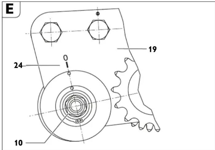
-OTnycTHe raiky (15,cm.pnc.A) KNIIOyOM pa3Mepa 46.
- NopobapuBaiTe Ocb (10) OTHoCHTeNbHO HAKnAaKN (19). 3aTARHNTe rany (19).
PnBpaueHnOcN (10) no yacobO CTpeJIke (B HappabHeHH peKyuero INHCTpyMeHTa) NINHnpeKyuero INHCTpyMeHTa CMeIaetCBnPaBO (HappabHeHne B3rJaDa pABHO nApbHeHIO ABHXeHn Tpy6oΦpe3epHO MauHHb).
PnBpaueHnO cno npTb YacobO CTpeIKn NINHnpeKyuero INHCTpyMeHTa CMeIaetcOOTBETCTBEHNO BNEBO.
MOHTAM DonoJIHHTenbHbIX 3BeHbeB cENH.

AnonHHTeBbIe 3BeHbIeN MoXHO MOHTnPOBaTb TOnbKO B npeAcMOTpeHHbIX AINr 3TOrO MecTx.
- CHIMITE CTONOPHOE KOJIbO (32).
-CHMNTe naNeU (33). - BCTaBbTe Heo6xOAnMoe KOJInueCTBO 3BeHbeB UeIN.
-3BeHbIeHNpa3INuHbIXpa3MepOB BXOaT B KOMPiJeKT PnHaJIeXHoCTeMaUNHbI. - BcTaBbTe naneu (33).
- MoHTpyTe HOBoe cTOnOpHoe KoJIbUo (32).
3aKpenIeHne Tpy6oΦpe3epHoMaunHbI.
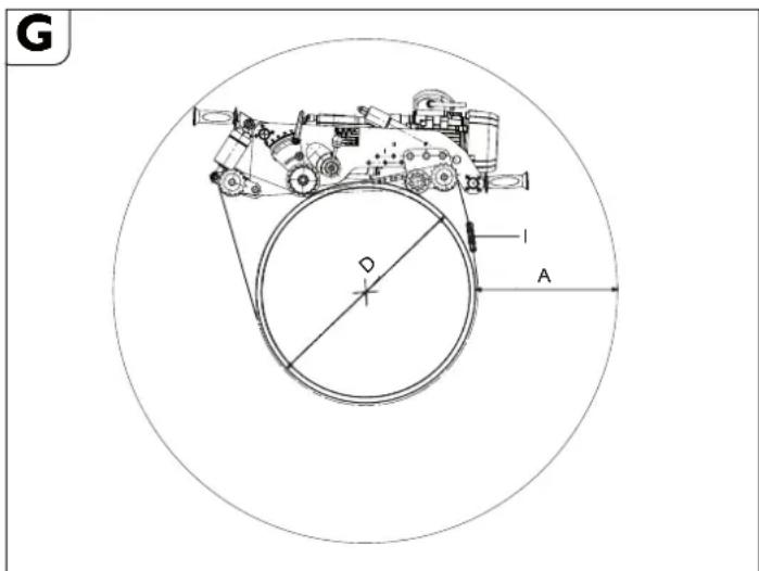
«A» Heo6xoAnmoe pa6ooyee npoctpaHCTBO npn Hau60nbwe rny6nHe pe3aHn.
«D» HapyKbI dHaMeTp Tpy6bl
《i》Hcno 3BHeB cenn npn dAmTe pTy6bD
RSG Ex 1500 A/B
| Положенияхов的好ocn | D[MM] [MM] | A[MM] [MM] | HДлина Zeелниоandingусторону | Одney длиноюпи | i* |
| 1 | 250300350400 | 400392384378 | 1427152516321744 | 2854305032643488 | 556668 |
| 2 | 400450500550600 | 381375369364360 | 17821898201921442273 | 35643796403842884546 | 6777778 |
| 3 | 600650700800850900 | 362357352348344340337 | 2302243325662702284028623001 | 460448665132540568057246002 | 889910101010 |
| 4 | 90095010001050110011501200130014001500 | 348345342340337335333331329328 | 3142328434283464360737513896406243384355 | 6284656868566928721475027792812486768710 | 101111111111111111111111111111111111111111111111111111111111111111111111111111111111111111111111111111 |
*Homep 3a3a3a 30231013027,cocTo8ueu H3103BeHeBbE AHHoH 635 MM.
RSG Ex 18 A/B
| Положенияхов的好ocn | D[MM] [MM] | A[MM] [MM] | HДлина Zeелниоandingусторону | ОБсяя длиныцени | I* |
| 1 | 250300350400 | 587576564553 | 1427152516321744 | 2854305032643488 | 556668 |
| 2 | 400450500550600 | 522511501492483 | 17821898201921442273 | 35643796403842884546 | 677777778 |
| 3 | 600650700750800 | 453445437429422 | 23022433256627022840 | 46044866513254045680 | 88910 |
| 4 | 8008509009501000 | 396393390386383 | 28623001314232843428 | 57246002628465686856 | 1010101011111 |
| 5 | 110501100115012001300 | 3900387385382379374 | 3464 036073751389640624338 | 6928072147502779281248676 | 11121212131314 |
| 6 | 1 | 3873 | 4355 | 0 | 87100 | 14 |
| 1400 | 382 | 4651 | 9302 | 15 | ||
| 1500 | 378 | 4950 | 9900 | 16 | ||
| 1600 | 373 | 5250 | 10500 | 17 | ||
| 1700 | 369 | 5553 | 11106 | 18 | ||
| 1800 | 366 | 5857 | 11714 | 19 | ||
| x | 1900 | 362A | 6162 | M | 12324 a | 20 |
| 2000 | 359 | 6468 | 12936 | 21 | ||
| 2100 | 356 | 6775 | 13550 | 22 | ||
| 2200 | 353 | 7083 | 14166 | 23 | ||
| 2300 | 350 | 7391 | 14782 | 24 | ||
| 2400 | 348 | 7700 | 15400 | 25 | ||
| 2500 | 346 | 8009 | 16018 | 26 | ||
| 2600 | 343 | 8319 | 16638 | 27 | ||
| 2700 | 341 | 8629 | 17258 | 28 | ||
| 2800 | 339 | 8940 | 17880 | 29 | ||
| 2900 | 337 | 9251 | 18502 | 30 | ||
| 3000 | 335 | 9562 | 19124 | 31 | ||
| *Homepr dlya zakaza uten 3 02 31 013 02 7, coctoansen 13 10 38eHbEbn no 635 mm. | ||||||
AIOOCTHKEHNOTTHMaBbHOPO npEaBAPTeNbHO HO HATXKeHnueHNOMOxHO NCIOJIb3OBaTb npINaRaMeBb INHTpyMeHTaBbHom KoΦpe NOnOBuHHbIe 3BeHbY eHINOH31,75MM.
PnHmep:
AII Tpy6bI dHaMeTpOM D=400 MM Tpe6yetc8 63BHeBbUeHIN (Homep AII 3aKa3a 302 31 013 027).
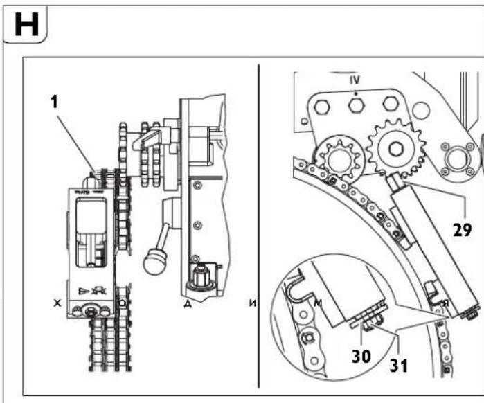
IbHHKeHne no Konee npn nomouin Beyuuei cenn
Co6epnTe BeauyuToeNb COOTBeTCTBryoUeN dInHb cornacho TaNHe
AIIA DIOCTHXKENH OINTNMaBHO rPpeABpntEhBOrHO HATRKeHHaIeNN MoXHO NCIOJIbO3OBaTb PnINaTaMeB E NHTCPymEtAlbHOM KoΦpe IIOOBHHbIe 3BeHbY eHN dINHOH 31,75 MM.
AinhaBeadyuee ceenn
| Диаметр Trусы | Длinaцени | Зевая堕п | |||
| [MM] | [MM] | 635 | MM | 63 | 5 MM |
| 250 710 1 | 1 | 1 | |||
| 300 870 1 | 4 | 0 | |||
| 350 1030 | 1 | 6 | 1 | ||
| 400 1190 | 1 | 9 | 0 | ||
| 450 1344 | 2 | 1 | 1 | ||
| 500 1500 | 2 | 4 | 0 | ||
| 550 1660 | 2 | 6 | 1 | ||
| 600 1809 | 2 | 8 | 1 | ||
| 650 1970 | 3 | 1 | 1 | ||
| 700 2130 | 3 | 4 | 0 | ||
| 750 2290 | 3 | 6 | 1 | ||
| 800 2440 | 3 | 8 | 1 | ||
| 850 2600 4 | 1 0 | ||||
| 900 2760 4 | 4 0 | ||||
| 950 2921 4 | 6 0 | ||||
| 1000 3079 | 4 8 1 | ||||
| 1100 3397 | 5 3 1 | ||||
| 1200 3714 | 5 8 1 | ||||
| 1300 4032 | 6 3 1 | ||||
| 1 4 | 0 | 0 4 | 3 | 3 | 0 6 |
| 1 5 | 0 | 0 4 | 6 | 4 | 0 7 |
Homep a na 3aKa3a 30231034010(1=635mm)
Homep 3aKa3a 30231036010(1=63,5MM)
Homep 3a3a3a 30231035010(1=31,7MM)
- PnKpeHTE BeAuyu 3a OAno H3 ABx 3BHeB UeIN K 3aXHMOMy YCTPOIcTBY PnN NMOOu6 BONTA H CTONOPHO KOnbua.
-1poAeHbTe Beyun yuactok Beayueen eenn noa obe 3Be3doyn Beayuenenn (pnc.H).
-ПркрпнTe CббОднКонeU,БeДушeI ueN K 3aЖиMHOMy yCTpoHCTBy npn NOMOu6oNTa n CTOnOPHOrO KOblua.
-Пилхнite BeaушуTo cenb K'tpy6e Nytem BpaueHnЯ WecTnrgpAHnka Ha 3aXHMHom yCTpoiCTBE (2). - PpOJoxNte BeAuyIO UeB Na pAcCToHnN 10 MM (OT pAnbueB npuBOaHOI cENN DO nAnbueB BeAuyEe UeIN) IN TpNkDa IPOBepbTe paCCToHne NO OKpyKHOCTN.
3aTARnBaTe yCTPOIcTBo HATRKeHnA LEN pNp NmOuPi eTCHrPaHHnKa (29) DoTexnopOKa 5aJb6a30 HeAoAeTO KOpNcyaCTPOIcTBa HATRKeHn ALENN (AMAnao3oH 3aKIMHa OK.50 MM). (MaKc.MoMeHT 3aTJKKn 50 H-M)


BHMMHHe - onachoctb Heecacthblx cnyaeB! Hb KOem cnyae He npokpyuBaIte TpN CTOnOpbIX BnHTa (31)Btopue. (cm. pnc. H)
3aKnHouTheIbHbIe pa6oTbI nocJe KaHDoRo npHMeHeHHA.
-BbIbeAHTe pa6oHn HnCTpyMeHT n3 Tpy6bl.
-BbIKIIOHTe Tpy6oOpe3epHyIO MaunHy.
-CHHMMTe pa6OuHn HcTpyMeHT.
- PackpoTe KpeHneHne Tpy6oΦpe3epHoMaunHbI.
XpAHHe rpyo0pe3epHO MAHHbI.
-3aunHTe HApxHbIe MeTaIIHuecknE qactn OT Koppo3n.
-XpaHnTe Tpy6ofope3epHy MaunHy B cyxom MecTe.
TexobcnyHnBaHne npemOH.
TexobcnyKHBAHne H peMOHT.
CJIeKTPnHCTpyMeHTAMN IN PnINaIeXHoCTAMN FEIN, Tpe6yHOuIMM peMOHTA, 06paauTecB, NoAnayCTa, B cepBNCHyO cyx6y FEIN. AApEc HaxoANTCB IVHeTHe HtBe6-caiye www.fei.com.
AkyaIbHbI CNICOK 3aIaCTeK 3OTMy 3NEKTPOINHCTpyMeHTy Bbl HauTe B IVItepehe No aDpecy: www.feln.com.
NcnoB3yTe TOJbKO OpUHnHaJIbHbIe 3aIyactn.
Pn HeoHMOCTB Bb MOHETe cMOCTOHTbHO 3aMeHtB CNeyHOue HcTb: pa6ouHe HcTpymEtB, pyKoTKn, ZeNb, 3BeHb aen

Maunhy pa3peaaetcnaonb3oBaTb tonkoB TexHmpeckn 6e3ynpeHOM
ctoHnn. HnoehHe bI INNOBpKAEHHe bpaOOhIE HnCTpyMeHTb I
KOMTOHEBTb He06XoAMHO HemeAENHHO 3aMeHTb Ha HOBie.
OnachoctbtpaBMPOBAAH
BCJeAChBHe HnpeHaMepeHHOro BKIOueHna.
IpeaIIO6bIMMaHmNpyuYnuaMnCtpy6ofoep3epHOMaunHO H3BNEkaTe WTeNCenH3 po3eTK!
06uhe yha3aHH
Pa6oTbI NO TexHnueckOMy 06cnyKuBaHHIO MOrY BbNOnHrTa TOnbKO 6oyeHHbI cneuaJIncTbI.
Pa6Otbl NO yXoAyn Texo6CnyxuBAHHO OXBaTbIbAIOT B OCHOBHOM:
HapyxHyIO OuCTKy Tpy6oΦpe3epHO MaunHb N cene KpenHeHa.
Bn3yaIbHbIKoHTpObnBcEtp6oΦpe3epHOaHHbl.
= Cmehy macna peAykTopa.
-Cma3kyXoOBOOpe3b6bHnueeN.
CzMkhy HapnabHIOUxN IHCTPmEnTbHOB mINHAdEbnHO 6aBKn B yctPOIcTBHe HATAKHeNn TpaHCNOPTpOBAHn.
-Bo3o6HOBnEHHnHaKneek n npdeynpeXeHn Ha 3NeKTPoHnCTpyMeHte.
YXoJ 3a 3BHeBbeBbIMN ueiAMN
ChaHana OCHNTHE 3BHeHb cHnO Tpy6bIX 3ARp3HeHn, 3aTe M ABraTe 3BeHbA cHnI TuaTeNbHO OCHNTHE IN POMMbOuHbM 6eH3HOM, KepoCHHom IIN NOoD6bHM CpeACTOBM.
AIIe oecneueHn CMA3Kn IIOONKHe OUYIe HbIe cEN Ha HeckoJIbKO YacOB B B3KToEkyuee MacNo, HApIMep, B TpaHcMncCOnHoe MacNo SAE 140.
Pmck BO3HMKHOBEHH Hecactbix CnyaeeB!
Pepe NOBTOPBHM NPMHeHEmn PObEaHTe TuaTeNBb BN3ayAbHb KOHToNb 63yPnHOrO COCTHO B3eHbueIe.3aMeHNToPBExKaEHHe NaCHn HEDocTAouHne CTOnOPHeK KOJIbA.
UHyp nHTaHH
PnnoBpeKdEHH WHypa NHTaHn3NeKtpOnHcTpymeHa WHyp DOJKeH 3ameHnTb PnOu3BOaNTeNb Hn ero npeAcTabTeIb.
Mexanh3m noaun Ha Bpe3aHne (cm. phc. A)
HapyKHa860KOBaI NOBepxHOCTb RaIKn C Tpy6HOJ pe3b6OJI (17) OJIKHA 6bITb BCERdA OUnIEHNOH OT 3ARp3HEHNI CNJEIOB PkABuHHBI NcERKa CMA3AHHO.
- Pn Cme He Macna peAkykTopa Heo6xoAMMO OHcTHTb H Cma3aTb XoOByIO pe3b6y.
DemyHTAM:
- 3BNEKHTE BNT CUNHAPNueCKOJ FONOBKOJ (8).
-13BNEKNTe 6oT (5) n3 KpblkN. - 3aTeM KPNBOUHIOH pyKoTko BbBHTnTE MExaHm NOaHn Ha Bpe3aHne H3 BaKn C Tpy6HOn pe3b6Oi.
- DeTAnCpe3b60HHeo6xOaHMoOuHCTHTb HcMa3aTB MaTOM (CM. pa3AeI 《Cma3OHyBle cpeAcTba Hcxema Cma3Kn》 Ha cTp.201).
-3aMeHHTe NOBpeKdEHHbIe rpa3ecbeMHbIe KOJIbLa.
Mortam:
MoTtAK OcyuCCTBnRETC B 6oPaTHOH NocNEAOBATENBHOCTn. He NobpeAHTe rpa3ecbEMHbKe KOJIbUa pnp MOtTake!
3aHHMHe yCtpoHCTBO
PpeoTbpaaate 3arpa3HeHne pe3b6by pbm-6ontob (3, pnc.1) B npyKHHOM CTakaHe.
Pn Heo6xoAUMocTH OuHCTHepe3b6y n CMAKbTe MaCIOM.
Cma30uHbIe CpeDCTBa H CXema Cma3KN
YctpaHHeH HeHcnpabHObTei (KoHCTpyKmR RSG Ex (^**)]
| Henschprabhoct Bozamochnii pleuchnch MepbI | ||
| Дыгателы рабочи инструment octанавливаютca | Очны Нзкая Temпература okружаший среды Испауший рашимсяногоне Масно FEIN | Плььшейные Нзкотемпецурачhoe Траимиссioногоне Масно FEIN |
| Затушия рабочи инструment 3амених chatош� | Инструment | |
| Нет наразжения в сети Поберът подкlioчинения к | сети И КOMмУТационье пізборь | |
| Нени раьлhoe наразжения в сети Поберът дади | псети КOMmUТационье к Сети | |
| Спшkom 6ыстая подачни спшkom вбокая позьдость себа мaterиала по оримету | Отreyшириные рeтуктор И\/Ии уменьшITE ГлБИну погуженья | |
| ПOTERи macna в рeтукторов Коробке Onpeдени | Мосто утук性和 устразиite ee - Долейte Maclio | |
| Чершени позьшени temпераусы в дhiratete | С hoBa Вкlioочи БLOK KMMyTuZIOHbIX пізборов 3 07 02 041 01 4 | |
| Повsprждане центов 3вeзdoчki Повsprждане звене zuюцуп chуногьяпьогьяпьогьяпьогьяпьогьяпьогьяпьогьяпьогьяпьогьяпьогьяпьогьяпьогьяпьогьяпьогьяпьогьяпьогьяпьогьяпьогьяпьогьяпьогьяпьогьяпвогьяпьогьяпьогьяпьогьяпьогьяпьогьяпьогьяпьогьяпьогьяпьогьяпьогьяпьогьяпьогьяпьогьяпьогьяпьогьяпьогьяпьогьяпьогьяпьогьяпбогупьогьяпьогьяпьогьяпьогьяпьогьяпьогьяпьогьяпьогьяпьогьяпьогьяпьогьяпьогьяпьогьяпьогьяпьогьяпьогьяпьогьяпьогьяпьогьяпьогьЯпьогьяпьогьяпьогьяпьогьяпьогьяпьогьяпьогьяпьогьяпьогьяпьогьяпьогьяпьогьяпьогьяпьогьяпьогьяпьогьяпьогьяпьогьяпьогьяпьогь亚 | Зюшени 3амени 3вeноцуп | |
| Нени раьлhoe-coeинене ци Поберът мcertа | соeинени Iипсравът | |
| Палец цelin Bстaven He noJIoNocstby Bстavenпалец | цelen Палочьюstvo | |
| Henschprasьнай траектора рezа Нени раьногьяпьогьяпьогьяпьогьяпьогьяпьогьяпьогьяпьогьяпьогьяпьогьяпьогьяпьогьяпьогьяпьогьяпьогьяпьогьяпьогьяпьогьяпьогьяпьогьярьогьяпьогьяпьогьяпьогьяпьогьяпьогьяпьогьяпьогьяпьогьяпьогьяпьогьяпьогьяпьогьяпьогьяпьогьяпьогьяпьогьяпьогьяпьогьяпьогьярбпь TpU66 | см. раздд«ПоД罗ТВКа Trpvбфоressesнй машинь (Cm.pinc.A)»Ha CTР.198И рAZdд«Зakpenlenes trpvбфоressesнй машинь Ha Tpv6e»Ha CTP.198 | |
| ОсутCTВи ЭКSUENTРNUHOCSTи habраляюшero BAana | Отreyшириные Точ�ocstх XODa, CM. рAZdд«《Hастroyka Точ�ocstх XODa»Ha CTP.199 | |
| Затушия раьлhoe рабених рабουч | Инструment | |
| Косе пizи вervikалhoe рacnoLoЖенage trpv6bl, небулгость trpv6bl | Исponsьзчын.Tanравл�юшee усточв, CM. «Зakpenlenes trpvбфоressesнй машинь Ha Tpv6e»Ha CTP.198И рAZdд«「Hастroyka Точ�ocstх XODa»Ha CTP.200 | |
| Перерузka рабочero Инструmentа | Отreyшириные рeтуктор И\/Ии уменьшITE ГлБИну погуженья | |
| Спнжени layingи оtcутствуюшая Фуншональbosьмшынь | Het habражени в сети Поберът подкlioчинения к | сети И КOMmyTuZIOHbIe пізборь |
| Выклочаел He bKloucen | Прobерът Выклочаел | |
| Прockалызване муФъ | Отreyшириные рeтуктор И\/Оправьtle Злесчpondирсчmenг NaZBOA, FEIN Ддя Hab相对较 Mоменту срабытван� MyФъ | |
| Чершернaya вибрацья | Спншkom 6ыстая подач | Отreyшириные рeтуктор |
| Рабочий Инструment onушen спшkom rIy6oko | Плodимитe рабочий Инструment | |
| Зжимнoi рычаг (11) He zatrayt. | Затянite зажимнoi рычаг | |
| Цelb ocra6леса | Прobерът Нatableоженьецeni | |
| Затушия раьлhoe рабочий Инструment 3амених рабουч | Инструment |
Rapantna.
IapaHTnHa H3dEInHe DeiCTByeT B COOTBeTCTBnC 3aKHOaTebHbIMN ppeINcHnHM, DeiCTByIOUIMM B CTPaHE BBODA K KcPnYaTaUNHO.
Pabouhe HnctpymEnTbH nppHaJdJIeHHoCTH.
ThNbHbIe DnCKN
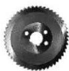
1
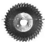
2
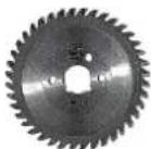
3
$$ \beta = 8 ^ {\circ} $$
$$ r = 6 m m $$
$$ b = 4 \mathrm {m m} $$
Tp6ofoep3epHa MaunHa He npn3NaueHa Dna:
-3acTocyBaHHr y 30Hax 3 Bn6yXoHe6e3neHIM cepeAOBmE.
-3actocyBaHHnHnA cnHbHM aoem ta poit nA BOAO.
3aCTOCyBaHHa 3a MeKamn Aiana3OHy Temnepatyp BiA-20°C A0 40°C.
-pi3aHHBn6yXoH6e3neuHXMaTepiIIB.
-pi3aHHraRopouxMaTepiJIIB.
HnpeKTHBa EC 94/9EG ATEX (Atmospheres Explosibles)
3BepTaMo Bauy yBary Ha Te, 10 Tpy6oep3epH Maunn HFein Tny RSG Ex (^**) He Oanyueshi Do 3aCTOCyBAHN Y Bn6yXOHe63neuHnx 30hAx, OTke AINx Tpy6oep3epHN MauHH Nemae cepTnphiKtB INpO6yBaHN TnnoBOrO 3paKa 3riAHO 3 AnpeKTHBOIO 94/9C.
(Ytpy6oΦpe3epHmMaunHi RSG Ex (^**) NIIe ABA KOMHOHeHTa - eNEKTOPOABUNYH I ODAATKOBIN BUMNKAY-BIANOIBaOTb BIMORAMATEX.) AnpeKTHBaATEX IAe NIIe Ha Tepntopii EC.
Hopotn no orna.
13aTncknn npncptpi
2KpinnnblnnrBnHTdN6iHoi nntu
3 BiHa nIITa
4IhOpMaia
5IporoHnH
6XoOBnTBNHT
7 MexaHImNoAquiHa Bpi3yBaHHr
8 BnHT 3 uINIHAPNHyO IO rONOBKOIO AIA MExaHl3My NOaui Ha Bpi3yBaHHr
9Pn3oHHnnpOroHn
10XoObaBicb
11 3aTnCKHbBaXinb
12BnHT3WecTnPaHHoTOJNOBKOHO
13 7aai6a
14 Bicb HaTgHeHHa
15 Raika
16 IhctpymehTaIbHa WnIHdIbHa 6aKa
17 Raika 3 Tpy6HIO pI3HO
18 KpinnblnhrBnHT ABnryHa
19HaKa
20 Bea3ipOuKa
21 TpaHcnpTnBn
22 Ctonophe KInbue
23 LTHΦT
24 Pi3b6Oba npo6ka iHCTpyMeHTaJIbHOI wNnHaenbHOi 6a6Kn
25 PyKoTka JnI nepeHeceHHa (i3onboBaHI noBepxHi pyKoTkn)
26 Kana rnnbnuHn
27 Taika 3 HakaTkoIO
28 BaXinb NepemHKaHHa WbNkOcTI NoaH
29 WecTnPapHHN npCTpoH HataRHeHHaHIOra
30 Wai6a npctpoIO HaTARHeHHHaHcIOrA
31 Ctonophi rBnHTnpCTpOHaTARHeHHNaHIOra
32 Ctonophe kInbue naHKn nauHcIogra
33 PporoHnHaNKn NaHcIOra
34IeTNIaI nepeHeceHH
ДяВаообeзн.
3araJIbHI BkA3iBKN 3TexHKn 6e3neHN.
TONEPEDEXEHHA
IpoHTaTe BcI BHa3iBn 3TexHkN 6e3neHH Ta IInCTpyKlU, O3HaHOMTecr i3 MaHIOHHAMn TaTexHCHMM
XAPANTHEPCHKAMH,IO DODAHOCTBOI OBOEENHTPOIHCTPYMNTA. HeBHKOHAHNA BKA3IBOK 3EXTKHMI TAO HCTpyKJI MOKE npN3BOAnTH O ypaKeHHN ENEKTPUHNM CTPYMOM, NOXeKI TA/ABO BAKKHX TpAMB.
3epirahe Bci npabnna 3 TeXHH 6e3neK H I Bka3iBHN Ha MaHoyTHc.
IIAn NOHATTAM ENEKTOPIHCTPymET),IIO BKNOPNCTOByETy BKA3IBkX3 TexhIKU 63neKn, MaTeBHa YAba3i eNEKTOPIHCTPymET, IIO pNaOIE bIA MepeKi (13 IHHYOM KJbHeHn) a6o bIA kMyrAToHPOIbGatapei (6e3 IaHpya KJbHeHn).
1]Be3neKaHa po604omy Micui
a) TpMHMaTe CbOe pOoBe Mue Cb V ChTOTI I 3a63neuty DoOpE ocBtIeHnna PoOoYOro MiCz. Be3NaA a60 noraHe OCbTIeHnHa paOoHOMy MiCiu MoxyTb Pnus3BcTNo HeUcaHINx BUnAkIB.
b) He npaouhe 3 eneKtpponpnaOAM y cepoOBnCi, de icHyc Hede3neKa BHOxy BNaCniOk npCyTHoCTI rpoUHx piHN, ra3is ao nny. EneKtpponpnaDN MoKyTb IopoAkyBaTIn iCKPN, BiA JAKX MOnke 3aMaTnCn nn aOp napn.
c)ПдсаocpoTH3eHNTponPnHnAOM He nIyNcaHTe Do po6oHOro Mucia ditei ta inuXh ocic. Bu MoKeTe BtpaTHn KOHTpONb Haa PnHnAOM, kkuO Bu He 6yAdete 3ocepeAkeHi BA HkOHAHHI po6OTn.
2]EeIeHTpHua 6e3neKa
a) Wtencelb enehtponphnaady noobhen niXoAnTH do po3eTN. He 030BONETBCMHH TcB wTcENcI. DnH pOoTH 3 eneHTponphnaamn, 10 MaHOb 3axHCHe 3aMeNHen, HE BHKOpHCTOByTe aadantepn. BnKOpHCTAHNN opriHaNBoHOro TseCNs Ta HaleKHOIT po3eTK 3MeHwYe PnIKU ypaKeHH eNeKTpHcHIM CTpyMOM.
b) YHHKaHte HOHTaTy 3a3eMnEHHMH NOBepXHaMH, Hn HApN. TpyBaAM, BatapeAHH OAnEHHN, NnTAMH TA XOnOdHbHHaMM. KOni Baue TINO 3a3eMnHe, IChy 36InbWeHa He6e3neKa ypaKeHH eNeKTPuHH CTPyOMM.
c) 3axuante npnnaB iD Douy i Boorn. IonaaHaHb BOAn B enektpopnpna3 36iNbye pnsNK ypaXeHHN eektpnHm CTpyMOM.
d) He BHHOPHCTOByte Ka6eBn DnnepeHeceHH enEnKtpponPhnady, niDsiWyBaHHa 0do BNTRyBaHH WTeNCen 3 po3eTHN. 3axmuaTne Ka6eBb Bi dTeNla, MaCTHNa, IOctPHx KpaIB Ta Detanei npHaNy, 1o pyxaToBcN. NwkoJaKeHH a6o 3aKpyeHH Ka6eBn 3iInbye pnsIK ypaKeHH eNEKTPnuHMM cTpyMOM.
e)ДЯЗOBHbHIXpoitO6OB'3aHOBOBbKOpHcTObYHTaHWE TaHmN OOBbYBaU,0npHaTaMHnIa3OBHbHixpoit.BbKOpNCtAHN IIOBbKyBaA,uOpo3paXoBAHnHa 3OBHbHiPo6Ot,3MeHwye pN3NK ypaXeHHEnEKeTpNCHMCTPymOM.
f) Ano He MoHa 3anobirn BnHOpctaHHo EneKtponPhady y BoIoromycepeoBnHui, BnHOpctOByte npHCTPII 3axKCHOro BmKHeHH. BnKOpctaHHI pNcTpoIO 3axHCOrO BmKHeHHI 3MeHUIy peu3NKypaxHeHH eJekTpUHHM CTpyOM.
3)Be3neKaIIODeH
a) 6yIbTe yBaHHMM, cnIkyTe 3a THM, 0o Bn poOHTe, Ta 6yIbTe o6epeHHMM qac poOToH 3 enEeTponpHnaDM. He HOpNCTyHTEcH enEeTponpHaJADOM, HxIO Bn CTomJIeHi aO 3hAxOHTeN Hi dIO HApHOTHKIB, CnHPTHN HOA NIKiB. MtH ByEyBaXHOt i pN KOPNCTyBAHHi enEeTponpHaJADOM MOKe npINBECTN AO cepNo3HHX TPABM.
b) Bdrahe OocHe 3axHcne CnpAHEHHa Ta 06OB'3HOBO Bdrahe 3axChiOyHnP. 3acTOcyBHaBH OocBcTOrO 3axHCnOro CnpAxKHeHHa, Ra HAp., -B 3aJIeXHocTi BiD bNAty PoSiT -3axChoI MaCKn, cneUzByTT, IO He KOb3aTeBcR, KACKn Ta HabyuHnKlb, 3MeHJype PN3IK TpABM.
c) YHHaHTe BnnaKnOBoro BMHHHn. Nepu Hm BBmHyTH eneKtpponpnaD B eeneKTPomepy 460 nId'cHaTHn AynMylrAToPHy batapeH, Opatn Horo B pynn a6o nepeHoCHTN, BnBbHtBCra B TOMy, 40 eNeKtpponpnaD BMMHHTN. TpmaHn NaIbUa Ha BmHKaui nIac npeHeceHn eNeKtpponpnaDy a6o nIaJIIOueHn B po3eTKy yBIMKHyTORO npHaMy MoKe Ipn3BeCTn Do TpaBM.
d) Pepa THM, RA BMKHATN ENENTPONPHAD, npheepitb HanaorOHyBaBbHI IHCTpymENTH Ta raHOBH NIOU. PepeSyBaHHa HanaoAxyBaHbHorO IHCTpymEnta a60 KNOuA BAcTHNI pHnA dy, 10 o6eptaTbcra, MoKe Ipn3BcETN DO TpaBM.
e) YHHKANTHE NHPPOHNO rONONOHNTHINA.30epiraHTe CTIke NOONHOHNA T 3aBmHn TPNMAnTE PIBHOBARY.Lae 3oBONITb Bam kpaue KOHTPONOBATn enkTPOPNpnaA y He63neuHNX cHTyauix.
f) BdraaTe npdaTmH Oar. He Bnrae Te npocToH Oar Ta npnKpach. He nCTabnHe BOLOCC H OAR DO Etanei, 10 pyxAOBc. IpocToH OAR, AOBE BOLOcc Ta npNKpaCn MOxTyb IOTpanNTu B DeTani, IO pyxAIOTBc.
g] Raio icHyc MOHnBicb MOnTyBaTH NIOBIDCMoHTyBaJIbHI aO0 NNOyOBnHOH O npHCTpO, nepeHOHaTReC, 0o BOH 6yn Do6pe NiEcHAni Ta npaBnHbNO BnKOpHCTOByBaHN.C. BkOpNCTaHH NIOBIACMOKToBAJbHOrO npHCTPOO MoKe 3MeHUnTI He6e3NeKn, 3yMOBneHi PNNOM.
h) Do6pe 3aHHa ENeHTpOIncTpymEtB, OtpMaHe B pe3yIbTaTI qactoro IX BnHOPCTAHN, He NOBHHo pN3BODmTH DO CAMOBNEBHeOCHT ITHOpYBaHHa PnHHuINb TExHHc Ee3NeKn. Ho6epeXHa AIO MoKe B OADHy MNTb Pn3BecTN DO BaKKoi TpaBMn.
4) PpabHbHe NOOBMeHHra KOpHcTByBaHHeNEKtpPnHaamN
a) He nepbentaHMyte npnlaD. BHKOPHcOByTe TaKm npnlaD, 10 CneiaiIbHO npn3HaenHm DInB iDnOBiHOi pooTH. 3 npNAtHM npnIaOM Bn 3 MeHNM pN3kOM OTpMaTe KpaJI pe3yIbTaTH po6OTn, RaIO OyAeTe npauOBaT B 3a3HaueHomy dianaoHI notyKHOCTI.
b) He HOPNCTYHTECE ENETPONPHNADOM 3 NOUKODHEHM BHMNKAYEM. ENEKTPONPHNA, AIKN HE BMNKaTeBcra aOe H BMMKaTeBcra, e He6e3NeYHM I Noro TpeBa bIaDEMOHTBYATn.
c) Npeed TMH, NK perynobath 0o-He6yab Ha npnlaDi, MInTH npnnaa a60 XOBATH pnnad, BHTHHTb WTENCEBIs i3 po3eTH Ta/ABO BHTHHTb anMyIATOPHy GatapeH, Hko BOHa 3HImaetbC. Li nonepeJkyBaIbni 3axoAn 3 TexHikn 6e3neKn 3MeHNWytb PNHK BnAkoBOrO 3anycky npnAay.
d) XOBaIte enEHTponpHnlaH, RKMn Bn came He KOpHCTyEcTeCb, Bid dIeR. He 3O8BONaIte HOPCHTyBATHcE ENETPPOPNJHaDM Oo6Am, Uo He 3AHOiM 3 Noro pOtoHO aOe HWTanu II BkA3iBHN. BkOpNCTaHH npHaIaIB HeAOCBIAUeHNmIOo6aMm MoKe 6TyH He6e3NeuHM.
e) Crapahno dornaaTe 3a enentpohcypemtAmn i npnaadam. NpebipraTe, 0o pyxomi detani npnady 63doraHNO npauobann ta He 3aianH, He oynn noohOHeHHM ao HactinBnN nohoDHeHHM, 0o ce Morno BnHHT na yHHIOHyBaHH eneTponpHaNy. NoohOHeHi detani tpebaDipemontyBatn, nepu HIN HopnctByatcH HmH 3HOB. Benika KInbkiCTb HeuaChnx BnAakB cnpuHHetbcra NorAHM OOrlaOM 3a enektpopnpnaadam.
f) TpHMaIe pIsaIbHI IHCTpyMeHTN HArOCTpeHHM Ta B YHCTOTI. CTapaHIO AOTnHyTI pIsaIbHI IHCTpyMEHTN 3 OCTpyIM pIsaIbHM KpaEM MeHsE 3AcTpyIOTu Ta neriwi B ekCpMyaTauII.
g] BnHOpHCTOByIte eneHTponpHnaIa, npHnaIaIaIO hBoO, pOoHi nIcTpyMeTHn T.i. BiNoboiHO do uHX Bn3iBOH. SeBPIT do yBaTH npu bOMy yMOBn poOTo Ta cneuΦiKy BnHOhyBaHOi poOToh. BnKOpNCaHH eNeKTponpHaIaIB IaIra Po6iT, Anr kXx BOH He nepeAbaYeH, MoKe npu3BeCTn DO He6e3neHnx CHTyaui.
h) TPhMaTe pyKoTHnI noBepXH 3axBaty cyXHH I nCtHMn, cnldKyHe, 0o6 Ha HxH He bnoOnHB aOpycToro MaCTHna. CnIsbki pyKoTKn I noBepXH 3axBaty yHEMOxKNBIOIOb 6e3neHyne NOBoAKeHHa 3 eNEKTpOHCTpyMeHTom Ta IHOr KOHTpONIOBaHH B HeOuyiKYBaHX cNtYauaJx.
5) Cepsic
a) BIDabaaTcBn npHaH na peMOHT Hnue KbaniΦIOBAHH MaixiBum Ta Hnue BHKOPHOpOgriHAno3anactHH. Lc3a6e3neuHTb po60Ty pNtCPHOIpTaHOM TpBNAHOhC
Oc06nbi Bha3iBn 3 texhikn 6e3neKn dIa Tpyo0peepnX MaunH.
IⅡIa YbIMKHeHH Tpy6oPpe3epHOI MaHINH,po6OTn 3 HeO Ta II O6cIyOBaHHaDToPMYTeCe HauIOHaNbHxnpnncB IooAo 3ano6iBaHHa HeuaChHM BnnaAkm
AOTPIMUHTEc3aKHOaBHyXdIpeKTHBIOAOBb6yO3axHCTy.
Cniakyte 3a CTIKNIM NIOKHeHm O6pO6nHOaHOI Tpy6n. HeoTpImaHHBkA3IBOK MOKe IpN3BecTH Do BAKKX TpaBM a60 CmeptI.
EeIeKTHHITpy6oΦpe3epHI MaunHH (HOHCTpyuia RSG Ex (^**)
Ha npyra y mepexi NobHHI BiAnOBiDaTH daHIM npo Hnpyry, Bka3aHm Ha Tpy6oepephi MaunHi.
IIaKIOueHH Tpy6oΦpe3epHOI MaunHn Heo6xIAHO 3axnCTHTN 3aNo6IXHKOM Ha 20 A.
Peynphno nepebipraTe MepekHm shyp i, 3n oTpe6n, nooBxbya!
IIaKIOUaHTpy6oΦpe3epHy MaunHy 60noka KOMytauiHnx npnnaIb IINue 3 BmKHeHm rOJOBHM BmNkAqem.
OnepaTop IOBHNHe3 3ABKAn MaTH AOCTYn DO 6Ioka KOMyTaJIHHN PpINaIB.
3actocybaHHa.
PyKoRTHN ta 130nbObaHNI NOBExHI 3aBMnMaHOb6yTH CyXHH, YCHTHMN I He 3aOpYDHeHHM OHBO HOHNCHCTHEHMM AcTHNOJ. KOB3KI pyKoRTKN Ta 130nbObaHNI NOBExHI 8e3OBAIOHTb 6e3neHuEckCnpyTaBYaTH eneKTPolHCTpymHt Y hepeA6aehnx ChTyaiIax.
Ipn poobotax, KOH pOoOH IHCTpymEn MOHe 3aueNTH 3axOBany eNEKtponpoBOnHy, TPhMaTe eJekTPOIHCTpymEn 3a I0JIbOaHI pyHOATn.
3aueHnEHH npoB0AKN, 0O 3haoAHTbcraPiA HAnpyroHO, MoKe 3apAkyBaTH TAKOK i MeTaeJIbI cactHNI eNEKTOIHCTpymEnTA Ta pN3BOuNT DO ypaKeHHeNEKTOHN CTPYMON.
He nepenabaHTaMyte Tpy6oep3eHy MaunHy. BHKOpHCTOByte dIPO6TH bIDIOBHIIN PO60H INCTpMEn. Pn4aTHN Po6oH INCTpMEnT OoBONRe npaO8bTN KpaTe Ta 6e3neuHIIe.
He BnHOpNCTOByTe ty6o0pe3epHy MaunHy 3 DeEeHTHM BmHHkaayem.
Tp6o6p3epHa MaunHa, 10 He BMnKaetbca a6o He BmNkaetbca, e He6e3neuHIO i notpe6ye 06OB'3KOBOrO pemOH TY.
BMMKAAH HJHJIeHH,NEHJ HAcTPOHOBH ENTPOHCTPMAO 3aMHIOHBAPOOHJ INCPTPMY. L1 nonepaKaByaBnI 3axoAn 3 TeHIXI 6BeNekn nonepaKaHyOt BnnaAKnob 3anyck Tpy60pe3epHO MaunHH.
He 03BONHnIe HOPNCTyBaTHcT py6oOpe3epHO MAaHHIO Oco6am, HJI He 3Haomi 3 Heo a6o He uHTanu IInctpykuio. y pasi 3acToCyBaHH HeaoBlaueHMOn OocbAm Tpy6oOpe3epH MaunHn E he6e3neHmMn.
Perynpho BHHohyTe TexHicHe OcbnyroBuHaHH TpyoOppe3epHO MaHHN.
IpeBipRte TyOoOp3epHy MaHHy Ha HABHcHt b NowKoDMHe, a TaOH iHHX
DAHTOPi, Aki MOHYb HeraTHBHO BNNHHTy Ha EKCnPyAutaHIO TpyoOppe3epHO MaHHH. IpeD BHKOpHCTaHHM HecnPpBaH NpyoOppe3epHa MaHHa NobHHa
dyTH bIDPeMOHTOBa. Garato HeuacHXs BnAdkB cnpuHHREbCnoraHm
DOrrAOM 3a TpyoOppe3epHNmuHHAMn
BnHOPNCTOByTe TpyoOoPpe3epHi MaunHH, npHnAaIa Do Hx, pOoHi nHCTpymEnTH ToIO B1iNbOIBNo Do BhaSibOK y uii IHcTpyuII 3 EcxnIyatauI 3 YpaxyBaHNM poOoH yMO Ta BnHOhyBaHN po0it. BnKOpNCaHH TpyoOoPpe3epHH MaunH AIIPO6IT, AII RAKNX BOHN He nepeAbaeHi, MoKe npN3BecTN Do He6e3neuHNxCytuaui.
PpHHn p6oTH (Hb. Man. A).
Ty6oΦpe3epHa MaunHa 3a DOnOMorO pIsaIbHOro Po6OHoro IHCTpyMeHaBlaipiae TaΦpe3epyOK epMei BlaIck Tpy6 bT npoknaAei HTPy6pnoBo4n.3aDOnOMorO KpinnbHOro nPcHPTPO KoMaHua BctaHOBIOeTbca Ha 3OBHmH 6KtpSyI O6bIra Tpy6 3308N3 aONOMORO BnAChO HmazHiM ypo6oi noaui.Y kocsti Pobovnx IHCTpyMeHtIB BkOpncTObYIObCk Kpyrnni NnAnbHbN Anckn AIN MeTaNy Ta npofinbl Hpe3n, pIsaHbKa KpOMka RKnX 3aneKHo BIA MATEpiany Tpy6 Moke 6yTN BVKOHaHa 3 BHCOKoERoBAHOI WBnAkoPi3aNbHO tani abo 3 TbePdo rOcnay.
HanaHTyBaHHraIIN6HHa3HHa3ADJICHIOETcRa 3a DOIOMORIO IHCTpymEnTbHOI WnIHNaEeBHOI Ga6Kn (18), RaAupHIpHO KpINITbCa DOO6 XHnIX NNT (3) i peryNtOeBc 3a DOIOMORIO XoAOBORO TBnHTA (6).
TpaHcnpTHnBan21)Aky3aONOMOIO TpaHcnpTHNX KOnl CTbOpoe pyx y meXax po6ooyi nOaoHi, npNBOaHTbcBa iA IHCTpyMeHTaNbHO rnnHdena Ype3 2 cTuHepu Hpe'auoi nepeaui.
- IOnaHa BMnKaTeBcra Ta BMnKaTeBcra 3a DOIpomoroIO BaxEnrpeMeHHH WbNkOciT NoaHi (28).ΦpKlHiMa MyfTa zaxHuae peaykTOp IOnaHi BiA nepeBaHTaKeHHa.
IhctpymteTaBnH mHHaBbO6epTaTcBcY oocBIO KOpCTKnx nIauHHNkAX. TOnobHn peAkyTOp 3I 3MaUeHHM y MaCtInbHn BaHi IAp nPiBeHn IhctpymteTaBnHO WnHdEaCKNaDaTeBc3 PnaHeTpHO Ta Yeep'HaHOro CTyneHB.
PeAkykTop pO3paxoBAHn TAKHM YHOM, 00 BnnaKObe ranbMyBaHH naHIOrA He npIN3BOAnTb Do noHkoAKeHb. Yc BANH peAkykTop o6epTaOTbc y niiAUNNHkXk KOeHN.
Pama Maunn H 3 OcMn Pnp3NaueHa A nB Eaehn no Tpy6i 3akpInneHoi Ha Tpy6i Tpy6o0pe3epHoMaunn, a Takox A nNepeaHi ycnb piaHn Ta Noaui.
-Пинacyваняо BiIIOBIaHOrO iAmTeP TaPy6u BnKOHyETbC3a DOnOMorOIO nepeHaIauTByaHHx OdoBooi cci (10).
JaHcOrn 3aKnipIneHHcKlaAaTbC3 OKePMx OHaKaOBHX NaHOK.
Knbkictb Notpi6Hnx naHOK a6o OOBKNHa naHIOra dNra 3akpinneHHa 3aneKHTb BiA 30BHIuHbO rAmetpa Tpy6n.
TpaHcnpTyBaHHa.
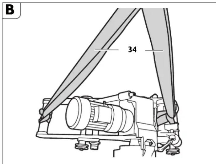
He63eNtepaBmHaHHn iac tpaHcnpTyBaHHn tyb00pe3epHO MaHHn. TpaHCnoptyIte Tpy6o0pe3epHy MaHHy nIIue 3a OOnOMOIO AOaAHX NeTEnIb IanepeHeehn (34) a60 KaHmaMeu HtpBox.
Peped noathaom po60TH.
Hebe3neKa TpaBMyBaHHaYepe3 HecNoiBai pyxH 3arotOBKn. FicCyHTe 3arotOBHy nepeo6koHO nla 3anobirAHn HeocnoiBaHomy nepecyBaHHIO.
PiA vac 6p06Kn 3arotOBKn icHy eHe6e3neKa HeCnOaIBaHOro BiKooyBaHH, NaIHnA abo 3cYBaHHa 3arotOBKn.
EcknyatybaTH MaHHy Do3BOnHCTbCn HmYe y TexniHo 6e3DorAHOMy cTahi. PepeKoXHM YbIMKHeHHM IpeEBiprae HaABHiCTb 3HOweHx a60 NooKOaKeHHx Po6OHy INCTpymEtTb Ta KOMNoHEHTB. 3HOweHl a60 NooKOaKeHr po6Oi IHCTpyMeHTn Ta KOMNoHEHTN NoTpiIbHO heraHOb 3AmHOBaTH Ha HOi.
Pi#roTOBui pOoTH Ha o6pOuHOBaHIN Tpyoi.
Tpy6n,pi3aHHraKHX Bi6yBaETbca Ha CkNaAcbKomMy MaDaHnyK,NOTpi6HO niApertn TaK,io6 NopeaHTu 3aTHcEHnpo6oOro IHcTpymenta.
- y pazi yknaaenehux tpy6 Ha ainrau 1OobxHIOo 1 M no BCbomy 3OBHIbOmy KOny tpy6n BiCTaHb DO CTiHKn KaHABN NOBHHO CKnaaATn He MeHwe 50 cm.
-06po6nIObHa NOBepxHr NOBHHa 6yTn BInbHa BiA 6py Ay Ta rpyHTy. 3a3aneriAb np6epiB 3 o6po6nIObAOHOI NOBEPXHi M'kI 3axNCHIOKpTTT.
PiaaBnPi06OuHInCTpyMeHT NOBHeH Bn6MaTnC HbAIOIHO MaTeplAn Typ6,Notp6HoF oOpMn 6oPo6Kn Ta oxOnOxHyBaNBo3MaUyBaNBO HorO 3ac6y.
- Pn6epitb 3BapHi wBn npuy i3 KOncam Ta naHcIorAm.
3a 0kNlaHluo IHopMaJIeO 3BepTae TcA IO nocTaHbNHaKo OXONoXyBaJbHO-3MaUyBaJbHnX 3acO6iB. (AN, TAKoXnHEBMaTHuHn OXONOxyBaJbHO-3MaUyBaJbHN npCtpi91201002004)
MactunbHn 3ac6 npn 0^
-MactnIbHn3aci6BIOCUT1-32132039000
-MactnIbHn 3acI6 BIOCUT 5 n-32132040000
Mactnblnhn 3aci6do 25^
-MactnIbHnn3ac61n-32132042000
-MactnIbHn3ac65n-32132043000
PiIroTobKa TpyoΦpe3epHoMaunHH (Hb.MaJ.A).
-BiAnyctItb 3aTnckHn BaxKinb (11).
P1HIMtB IHCTpyMeHTaBHy IINHAnbHy G6Ky (18) 3a DOnOMorOIO kPNBOWnHOIpyKoRTKn (y yTNIpI 3 IHCTpyMeHTamn) Ha mExAHi3Mi NDoaHi HbPIyBaHHA (7).
Buaanitbpn30HNI nporohu9 (9) i nepeCTaTe xOABoy Bicb (10) 3riAHO 3 AaHMMy Ta6NHI (4) BIaNOBIAHO DO HAeBHORO 3OBHIbHoro AIaMeTp aTy6i.
3HOByMiUHO 3aTgHiB npn3OHHI nporoHnH (9).
RSG Ex 1500 A/B (^**)
| P | D [MM] [Аюймов] | |
| I 250 - 400 9,8 | - 15,7 | |
| II 400 - 600 15,7 | - 23,6 | |
| III 600 - 900 23 | 6 - 35,3 | |
| IV 900 - 1500 35 | 5,3 - 58,9 |
RSG Ex 18 A/B (^**)
| P | D [MM] [АюймIB] | |
| I 250 - 400 9,6 | 15,7 | |
| II 400 - 600 15,7 | - 23,6 | |
| III 600 - 800 23 | 6 - 31,5 | |
| IV 800 - 1000 31 | 1,5 - 39,4 | |
| V 1000 - 1300 39 | 4 - 51,2 | |
| VI | 1300 - 3000 | 51,2 - 118,1 |
P:ПОJOXKeHHxOaOBoi Oci
D:Дiamettpу6n
BucHybTe 3aTnckHi npctpo1 (1) nlaHauorib nla 3akpinneHH hnnxom 06epTaHH npyXHHoro cKaHa, o6nicra BCTaHOBBNEHH Tpy6oΦpeHoi MaHH 6yIO DOCTaTHbO MICuA I3aTnCHHeHH.
CknaIb naHOr a n3akpinieHHy BiAnOBiHOCTI 03OBHIHBoro iAmetpa Tpy6n.
Po3auyTe Tpy6oΦpeepHy MaunHy Ha Tpy6i 3aΦikCyuTe II niAioHMnM npHcTpoE M,06 MaunHa He 3MiCTnIacb.
CknaTb BeAynn NaHIOr Ta npncptri HaarHeHHaNaHOra y BiNOBiHOCTI DO 30BmHbO rIoAmeTp aTy6n.
3akpiniTb BeaynnaHIOHa BiAcTaHI 10 MM npuy i3 naHIOrOM aIaKpInHnHn HABnpOTn ppeepyBaHBOHO IHcPymHe. BIACTaHb BiA nporoHnHa Beayoro NaHIOra DO nporoHnHa NaHIOra AII 3akpInHnHnCKnAae 10 MM.
- Nepebipte BiCTaHb NO BCbOMy NepmEtpy He MeHwE Tpbox pa3iB.
3aKnipIneHH Tpyo0Φpe3epHoMaHNNHaTpy6i.
HaKaNaDaHHaHKnOBHX NaHcHOrIb.
- PpoknaiTb Ⅲe BiAkpntI naHKoBI naHIOrN 3 06ox 6oKIB Tpy6oΦpe3epHOI MaunHH no Tpy6i.
- PnHnIHmIty Tpy6ope3epHy MaunHy i npoeiBt IaHkoBI aHaIcHRI niA 3ipOchAMn (20),IO6 nCnI pyKnPAeHNr Tpy6ope3epHOI MaunHH NaHKOBI naHIOU YbIuN y 3y6uAMn.
IpoBeaItbBnBHI KINUJI NaHKOBNX NaHIOIRIB HA3 3ipoQkAMN OCI HATRHeHHA (14) iHaKnlaKoHO (19).
3aMKHtB 06nBa KIHJI NaHKOBOro NaHcIora nporohyem (3 02 17 216 00 4) i 3akpinitb ABOMA cTOnOpHNMI KINbUAMN (4 26 34 020 00 5).
HaTHryBaHHaNHOKBHX NaHcHOrIB (nB.MaI.A).
Cnoataky 3nerka npknai t b naHKOJI naHIOI AO Tpy6u IINXOM o6eptanHHO60x npyKHHHX CTakAHIB (1).AnaTOUHIWO BnPIBHOBAHH Tpy6ofoep3epHOI MaHHN HekinbKa pa3iB nocyHbTe II ekinbKa pa3iB y 6ox HapmaKax.
- IINIXOM NOBEPaHHN ppyKHHHx CTAKAHIB HATARHITb NaHKOBI NaHcORn TAK, IO6 wTHOT (23, Man. A) N0TpanHB y nO3oBxHNI OTBIP npyKHHHO CTaKaHa y MEkXn NsA no KONY TPy6n.
-ⅡA qac npocey piaaHHN cniKyte a noNoxehnMaHTnФa. JaKIO Tpy6a He Kpyrno, NaHcior notpIbHO nIaTaryBaTH a 06nocNa6nOBaTH. Pepea npoaeDpoio p3aHHN 3HimIty bc 4 pykOtKn.
He6e3neKa Heuaachoro BnnaHy!
He 3aTayyTe npyKHHH CTaKaH 3a Meki uei TOuyk!
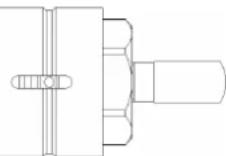
MohtakpobooHx hctpymehtib.
He6e3neKa TpaBMH
IChye He6e3neKa TpaBMyBaHHa Yepe3 HeHaBMnCHe YbIMKHeHHa. Pepea MoHTaxkem po6oOOro IHCTpyMeHtA BHTaRHTiB WTeNCb 3 pOeTkn.
He6e3neKa TpaBMH
IChy He6e3aek npiaiyee3 roctpi piaanbhi kpoomn po6o0rO IHCTpymHa. PIA lac MOHTaKy Ta dEmoHTaKy po6o0rO IHCTpymTa HOitb 3axnci pykABKNK.
He6e3neKa TpaBMN
He6e3nKa onlky chepe rapuyn po6oyn IHcTpymENT. Pia cac dmoHTaKy po6oyoro inctpymenta Hocit baxnci pykabuyn. Baraatte 3axnci pykabuui.
BdraTe 3axnchI pykabni.
BnKOpNCTOByTe Nnue po6oqi iHcTpymEnTn 3 6e3aOraHHo piaaIbHOIO KpOMKOIO.
-PepeMOHTaKEM NOTpi6HO OuHCTnN pRirHHI Ta NOcaKOBi NOBepxHi HcTpyMeHTaJIbHorO WINHAdEJa.
-MoHTyTe po6OuH IHcTpymeH 3 p03nlpHmN wA6aMn.
MiUHO 3aTARHITb 3aTNCKHy rauKy iHCTpyMeHTa.
Noatok po6oth.
Tpyo0dpe3ephaMaunHa:
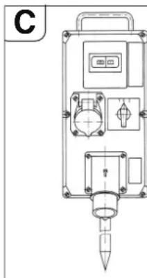
IIaKIOaTe Tpy6ofope3epH Maunn H 3 eJeKTponpHbOAM CnoTuATy Do 6Joka KOMyTauiHINx PnHnAID, JKN CKNaAdεTbc3 HActynHIXN KCMIOHETB:
-10OBHHBIMHKa/peBepcNBHBNMKNa,3axnCHN BIMNKa eekTPOdBnyHa
-po3'EnybaHmIMInbHOHnpyrH, -WTeNcBHI po3'MH.
TOnOBHHBMHKaayBHKOPHCTOBytcbA
YBMKHeHHI AINpeBepCyBaHHN HApPMAKy
06eTpAH.3axCHNHBMHKau ABHyHa I
pO3'EdhyBaMihImaHbHOHappyr YTBOpOHTb
EHNH ByoJ. Y pasi nepeBaHTaKeHH
CnPaUbOByc 3axNCHI BMHKau ABHyHa, y pazi BMKHeHHH HApPyr y MepeXi po3'EdhyBauch
MIHimaJIbHOHappyr BIAKnOaee Tpy6oOpe3epHy
MaMHNY BiMepeXi DAn3oBiirAH
HEHaBMnCHOM NOBTOPHOM 3anyCKy.
AIOBTOPHOYBMKHeHHrTy6oep3epHOI MaunHnNotpiio 3aiaTn 3XNCHI BIMNKa4 ABNryHa.
BLOK KOMyTauiHnX npnaIIB NOBHeH 6yTH PO3aObaHn TAK,IO6 onepaTOp 3ABKAN MAB DO HbOro AOCTYII.
Tpyo0oep3ephaMaunHa yactKOBo BHOyXo6e3neuH KOHcTpyu:

Ipea6NOKOMKOMytauiHnX npuiaIBNtpi6HO BCTAHOBHTNI KOMytauiHny Kopo6Ky 3AoATKObIM BMNKaem AJnYBIMKHeHHr Tpy6oep3epHOI MAHN H y BN6xOHe63neuHnx AdNbHux 30Hn 2.
KOMytauiHa Kopo6ka NOBHHa 6yTH
po3aWOBaHa TAK, uo6 onepaTOp 3aBXAN MAB O
Hei octyn.
He6e3neka Bn6yxy
Po3aOByTe 6nok KOMyTauiHnx npnnaIb 3a mExAMn 30n2.
Ecnnyatauia.
He6e3neHa TpaBMH
PiA cac po60Tu 3axuChn KoxyX NOBHeH 6ytN NoCTiH OaKpHTn i 3a6NoKOBaHn!
Hebe3neKa TpaBMn Upe3 ctpyKky, 10 po3niTaTbcB
CTpykKa MoKe CnpuHHHT TpaBMn. CnIaKyTe 3a Tm, uo6 y He6e3neHHi 30HI He 3HaXoAnNnCra IIOuN.
He6e3neka nomemi uepe3 ctpyky, 0o po3niTaebcra
CniAkyTe 3a Tm, uO6 y He6e3neHi 3oHI He 3HaxOAnnncnnerko3aMnCTi Matepiu.
He6e3neKa TpaBMN
PiA yac yBIMKHeHH Tpy6oOpe3epHOI MaunHn icHyE He6e3neKa TpaBMyaHHa Ype3 YacTHHH, IIO pO3NIaHTbC. IpeA KoXHHM BHKOpHCTaHHMaY6oOpe3epHOI MaunHH npi6npaTe KpNBOuHHny PYKoRTKY.
IpoeUpa 3anycny
Y pasi Tpy6oΦpe3epHnx Maun H eEKeTpOpiBODm Heo6XiHO nepekoHaTmca y TOMy, 0u HaprMOK o6eptAHn po6OyOr IHCTpyMeHTa E npabHbHM.
HaHpAMOK 6epeTAHnpePmKaeTbcrapeBepCnBHnBMnMkaem Ha KOMyTAUHOMY 6noi.
He6e3neHa TpaBMH
PiA qac po6oTH MaHINH icHyE He63neKa TpaBMyBaHHa Ype3 aCtHN, oO o6eptAObTc. A0 He63neHoI 3OHN MaHINH DO3BOJrEtBCr BXoANTn NIIe AIO p6iT 3 HanaHTyBaHHa 3 AOtpMaHHa 3axoAB 3TexHIKu 6e3neKn.
-BmKHiB npNbiA 3a OOnOMoIO BaKeIe I nepeMnKaHHBaNkOcTi noDaYi (28).
- YbimKHiTb Tpy6oΦpe3epHy MaunHy.
Bianycttb 3aTcknn Baxilb (11) i 3a Donomoroo KpboonHIOI pykoarTKn oncytib nIIaIbHH dNCK, kHK o6eptaTeBCA, kOMORA rI6we y Tpy6y. IIN6OKO 3aHyyENI INIAHbHH dNCK cta6iInye pioec pia3HH.
PiA vac fpeepeyBaHHBn6paTte 0HaaMeHHe3aennneHHIhCTpyMeHTA. O6'EM HAp13aHH CTpyKKn 3pocTae 3bIbWeHHm rIn6HHPi3AHJ.
3aHypTe p6oOuH INCTpyMENT pnp6n. Ha 3 MM rnn6we, HIX Ntpi6HO, a nOTIM NOBepHb IHO rno HnTpi6Hy rnn6HNy. PpN cboMy po6oOH INCTpyMENT BHXoAMTh Ib 3aueenneHH.
- y pa3i BnKOpHCTaHHI kKaII IIN6MH H aIte Po6OOMy IHcTpymeHTy DToOPKHYTHcAo NOBepxHI TPy6i. BiAncyITb FAky 3 HaKATKOIO (27) I BCTAHOBITb BkA3IBHNK (28) Ha 0.3HOby 3aTARHITb FAky 3 HaKaTkoIO (27). BiAperyIbBOABHy Fm6NHBy Bi3AHN MOHXa PPOuNTaH b HAKI.
-BmKHiTb Tpy6oOpe3epHy MaunHy.
-Notim 3aikcyte HanaitybaHHaJXOM 3aTAYBaHHa 3aTHCKHOrO BAXeJIa (11).
-3HOBy yBIMKHiTb Tpy6oΦpe3epHy MaunHy.
-ByIMKHTb npNIBA 3a OIOIMOROIO BaxKeIe IepemHKHaHb WbIKKOCTI NOaHi (28). - Kkuo Oa3B0nIe NOTyXHlCt b ABuRyHa, P0sPJIKe TcIHKy Tpy6n 3a OAnH pa3.
I PpoknaeHI Tpy6m MoKyTB nIac pi3aHH 3MHHTN CBOE NOHOH H IaTHCHyTN PO6OHN IHCTPymeT y po3piI. Ype3 ue Heo6x1dHO 3a PIa3aNHM IHCTPymeHOM Ha perynapHBI BcTaHI B6NBATn y po3Pi DAHaI KNHN.Y Bn6yXoHe63neuHX 3OHAX BNKOpNCOTByTe KNHN (6 33 05 013 00 2) (OdaHe npnaad RSG Ex 1500 A/B ( ) ) i MONOTOK 6e3ickpoBOro MaTeplany.
-3an06iraTe nepeBaHTaKeHHIO Tpy6ofope3epHOI MaunHn.
-HepeBaHTaKeHHn E HaBnM, kIIO nIa cA bIpyBaHHn po6oYOr IHCTpyMeHTa, 0o o6ePaTeBcR, KInbKlcTb o6eptIB ABrHyNa NOMTHO naae.
-Yepe3 ue OAnHouaCHO NaAaB BInpo6HiCTb p3aHH.
3aikcyte 3arotobky (biap3ok ty6n) i nonepeAbte ii naIHna.
Yp31 Tpy6 3 TOBCTMn CTIHKMn (s>10 MM) KpaI AJI 3BAPIOBAHN NOpti6HO 6o6p6nTn 3a ekInbKa npoxOIB.
OHaKOBaΦopMa po3piy 3aJIeXHTb BiA HAcTyNHx ΦaKTOpIb:
BnpiBHBIObAHN Tpy6ofope3epHOI MaunHn nepeaTkoM,
-BiAXHHeHHReOMeTpHuOΦOpMN Tpy6n BiAΦOpMN Kona a6o uNiHaPa,
-rocptpo hpooyor IHcTpyMeHTa,
-TBepocT MaTeplany Tpy6n.
Tp6o6pe3epHa MaunHa BlperyIbObaHa TAK, 00 y pasi IaMeTpa Tpy6n 300 MM i 600 MM NoaToK i KHeu b NiiH piaHH npakTuHHO 36iraotcbra.
Yepe3 ekcIeHTpHHiCtB HAnpMHorO Bana MtKa HanaWtYbaHHa (24, AHB. Man. E)
ۊiioHOIeAaIbXBoxAImetpIb.Ypa3I GInbIXx AImetpIb Tpy6MoKe 6yTHnOTpI6He OoAtKOBe peryIOBaHH.
3aDhi xiT pyo0peepnMaunn (RSG Ex (^**)
ToHNOHeHHMaTepiJIbHNxCInHOcte!
Ppea NOATKOM 3aHbOro XoAry Tpy6ofopeepHOI MaunHH Heo6xIAHO BIVECTn POBOHIN HCTpyMeHT 3 Tpy6n A'JRA3ano0iHaHH NooKOdKeHHIO poGOHOrO IHCTpyMeHT I peykTopa.
-BmKhtb npnBla 3a OIOMOIO BAKeJIe IepEMNKAHII WbNkOCTI NOaHi (28).
BiAnyctiB 3aTnckHn BaxKinb (11).
-BnBeAdtbp6oOuHInCTpyMeHT 3 Tpy6n.
YctaHOBITb rOIOBHn BmMnKaaypeBepCnBn BmMnKauy noIOKeHHA 0 (204 (BMK.).
-NepeMknHtPBepcBHN BmNkau y NOJNOKeHHa 3aHbOro xOy.
MiH0 3aTnCHiB 3aTnCKHH BaxKnb (11).
- YbIMKHiTb IIa 3a OIOOMOIO BaKeIa nepeMnKaHHaBnAkoCTi IooaHi (28).
Tpy6ofope3epna MaunnHa He npH3haeHa nI p3aHH niA qac 3aHb0rO xOxy! Bka3IBKn 100 oxoOdoKeHH I 3MaueHH.
ToHokHeHH MaTePiaIbHNx iHHocTei!
PoOvHn IHCTpymEt N1aC aac fpe3epyBaHHN nOTpiH6 OXoIooJxByaTH i 3MaUyBaTH. Y pasi HeoCTaHbTO OOnOJxKeHHN I 3MaueHHN cTpyKk MoeZ 3akHNHTncB. Lc Moe Np3BecTN DO NONOMK PoObOHO IHCTpyMHTa.
Iotpmytech inopmaui/Bka3ibOK Bhp06HHKa OxIoNDHyBaNbHoro 3acOby, 00 3actocobyctc
YabyHHI ty6n 3aBkAn Notpi6H0Pi3Tu y cyxomy cTahi 6e3 aactocybaHHOxONoAxyBaHbHO-3MaUyBaHbHoro 3aco6y.
-ΠπηλβHπ ΣκC a60 φpe3y Σλη pI3aHn HεneroBaHnx cTαneBnx Tpy6 nOtpiδHo 3MaúγBaTH MmNbHOIO BOAOIO.
HaiaatbyaHHnTouHocTi xOy.
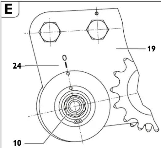
BiNyctiTBraKy(15,AB.MaJ.A)KIIHOyem3po3Mipom46.
IpOKpyuTe BcB(10)BiADHOCHOHaknaKn(19).
-3akpyTITbraiky (15).
y pasi nobeptaanx odooio ci (10) 3a cpiinko roaHHnka (y hapanpkmy
oeptanna po6oory IHcptrmHa) po6ouh IHcptrmHT 3MIuYbCpaBOpuy
(hapanpmoK ORIy y HapnPKy pyxTy pr6oepe3epHO MaunH).
y pasi nobeptaanx xo0oio oci npTo n cpiKNr OaHHnka po6ouh IHcptrmHT
3MIuYbCpa libopyu.
MOHTAHI DOATKOBHX JAAHOK JAAHCORA.
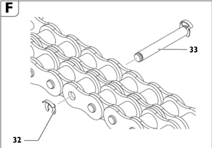
OdaTkoBI naKNH Oo3BOJnEbCMAOTyBaTH NmUe y nepe6aueHX dIa UboTO MICx.
3Himitb cTOnOpHe KInbue (32).
-3HIMITb IPOTOHOHm (33).
-YcTpOMiTb NOTpi6Hy KINbKicTb NaHOK NaHICrora.
JaHKn NaHIOra p3HHx po3Mipib MICTaBcR y KOMnneKti npnaAADr O Maunnn.
-yctpomitb nporohny (33).
MoHTyIe HOBe cTOnOpHe KInbue (32).
3aKnipJIeHHa TpyoΦpe3epHoMaunnn.
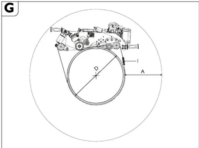
«A»notpi6hni po6oyn npocipt 3a Hai6iNbwoi rHn6HHPi3aHH.
«D» 3OBHiiuHi iAmEt pTy6n
«I» KIIbKlcTb NotpIbHx NaOH AnA IaMeTppy6n «D».
RSG Ex 1500 A/B
| Положенаяхозовoi оci | D[MM] [MM] | A[MM] [MM] | ПДовжинаразиога на одney 6ik | ЗагалваТДовжинаразиога | i* |
| 1 | 250300350400 | 400392384378 | 1427152516321744 | 2854305032643488 | 55666 |
| 2 | 400450500550600 | 381375369364360 | 17821898201921442273 | 35643796403842884546 | 67777788 |
| 3 | 600 | 362 | 2302 | 4604 | 8 |
| 650 | 357 | 2433 | 4866 | 8 | |
| 700 | 352 | 2566 | 5132 | 9 | |
| 750 | 348 | 2702 | 5404 | 9 | |
| 800 | 344 | 2840 | 5680 | 10 | |
| 850 | 340 | 2862 | 5724 | 10 | |
| 900 | 337 | 3001 | 6002 | 10 | |
| 4 | 900 | 348 | 3142 | 6284 | 10 |
| 950 | 345 | 3284 | 6568 | 11 | |
| 1000 | 342 | 3428 | 6856 | 11 | |
| 1050 | 340 | 3464 | 6928 | 11 | |
| 1100 | 337 | 3607 | 7214 | 12 | |
| 1150 | 335 | 3751 | 7502 | 12 | |
| 1200 | 333 | 3896 | 7792 | 13 | |
| 1300 | 331 | 4062 | 8124 | 13 | |
| 1400 | 329 | 4338 | 8676 | 14 | |
| 1500 | 328 | 4355 | 8710 | 14 |
*Homep 4n3aMOBHeHH 30231013027 naHOra 310 NaHOK DOBXNHOIO no635 MM.
RSG Ex 18 A/B
| Положенияхозовoi оci | D[MM] [MM] | A[MM] [MM] | ПДовскиепаль religа на обинибik | Загалын Довскиепalmцюга | I* |
| 1 | 250300350400 | 587576564553 | 1427152516321744 | 2854305032643488 | 55668 |
| 2 | 400450500550600 | 522511501492483 | 17821898201921442273 | 35643796403842884546 | 677788 |
| 3 | 600650700750800 | 453445437429422 | 23022433256627022840 | 46044866513254045680 | 889910 |
| 4 | 8008509009501000 | 396393390386383 | 28623001314232843428 | 57246002628465686856 | 101010101111 |
| 5 | 110501100115012001300 | 3900387385382379374 | 3464036073751389640624338 | 692807214750779281248676 | 111212131314 |
| 6 | 114001500160017001800190020002100220023002400250026002700280029003000 | 3873382378373369366362359356353350348346343341339337335 | 4355046514950525055535857616264686775708373917700800983198629894092519562 | 8710093029900105001110611714123241293613550141661478215400160181663817258178801850219124 | 1415161718123242122232425262728293031 |
*Homep 113 aMOBHeHHa 3 02 31 013 02 7 NaHIOra 3 10 NaHOK DOBXHOO 10635 MM.
AIOAORAHHEHNOHTHMABHO NONEPeAHBOrO HATRHeHHN AANUORA MOXHA BHKOPHCBOyBaTHoAOaHI yFyTnpi 3 IHCTPmENTAMn NaHKn NaHcUORA DOBxIKHOIO B13,75MM.
PnHna:
AIIpy6IaIameTPOM D=400 MM NtP16HO 6 NaHOK NaHcHOrA (HOMep AIN3AMOBNEHH3 02 31 013 027).
Pyx 3a cmyroo 3a donomoro 0 Beyuoro nauuora

H
KnaiBbeAynnnaHOr biAnobiHOIOBxHHN3riHO 3a6nueo AdoocHEHNONTHMaHbHO NOpeAHBoro HataRHeHHNAHOra MoKHa BOKOpNCBOyBaHTAoAHI y OyTnpi 3 IHCpymeTAMn NaHKn NaHOra DOBHXHO BID 31,75 MM.
OoBxHaBeAyoNaHIOra
| Даметр.Tруби | Довжина.Lанцюгa | Палки палцюгa | ||
| [MM] [MM] 6 | 35 MM 63,5 | MM 31,75 MM | ||
| 250 710 1 1 | 1 | |||
| 300 870 1 4 | 0 | |||
| 350 1030 | 1 6 1 | |||
| 400 1190 | 1 9 0 | |||
| 450 1344 | 2 1 1 | |||
| 500 1500 | 2 4 0 | |||
| 550 1660 | 2 6 1 | |||
| 600 1809 | 2 8 1 | |||
| 650 1970 | 3 1 1 | |||
| 700 2130 | 3 4 0 | |||
| 750 2290 | 3 6 1 | |||
| 800 2440 | 3 8 1 | |||
| 850 2600 | 4 1 0 | |||
| 900 2760 | 4 4 0 | |||
| 950 2921 | 4 6 0 | |||
| 1000 | 3079 | 4 8 1 | ||
| 1100 | 3397 | 5 3 1 | ||
| 1200 | 3714 | 5 8 1 | ||
| 1300 | 4032 | 6 3 1 | ||
| 1400 | 4330 | 6 | 8 | 1 |
| 1500 | 4640 | 7 | 3 | 1 |
HOMEP43aMOBHeHH30231034010(=635MM)
Homep 3n3aMOBHeHH 30231036010(1=63,5MM)
HOMEP4J3AMOBNEHHRA 30231035010(1=31,7MM)
PnKpInIb Beaynn NaHcHr 3a OHy 3 ABOX NaHOK NaHcHOra DO npCtPOH HATRHeHH NaHcHOra 3a DOnOMoROIO pOROHnu i CTONOPHO KINbua.
- PIOBoeAITb BeAuy AIIHky BeAyuO raHaIcIra nIa O6nABI 3ipoKu BeAyuOro naHua (MaI. H).
- PnpkinBb BInhN KIneBc BeAyuOra NaHOra Do npncToHO HataRHeHHaHOra 3a DonOMoro nporOHnu aI cTOnOpHoro kInbua.
- PnKnaIb BeAynn NaHciO r O Tpy6n WJnxom ooeptaHH WeCTnrpaHHKa Ha npiCtpoi HATrHHeHH (2).
PpoknaiBbEaynnHaanuHgBaIaCTaHI 10 MM (bi nporoohiv npnbHOro naHOra do nporoHnHb BeAyuO nauKora) I nepeblte BlCTaHb TPHU no nepimETpy.
3aTtckai Te npiCTpH HATRHeHHH HANUOra 3a OONOMOIO WIEcTHPahnika (29), NOKI shA6a (30) Ha Kopnyi pncTPO HOATRHeHHH HANUOra (1aIana3OH 3aTHCKAHH Pm6B.50 MM). (MaKc. MOMENT 3aTyrBaHHN 50 H-M)
Ybara-He63nHa HeuaChnx BnnaAdkib!


YXoAHOMy pa3I He npokpyuTe Tpu CTOnopHi RBHTn (31) Ytopui. (AIB.MaH.H)
3aKJIOHoyi po60TH nicra KOHHoro 3actocybaHH.
BnBeaItbpo6OuHInCTpyMeH3Tpy6n.
BmKHiTb Tpy6ofopeHy MaunHy.
-3HIMITbpo6oounIHCTpyMeHT.
-Po3kpHnTe KpinnHeHHr Tpy6oOpe3epHoT Maunnn.
36epirahn rpyo0pe3ephoMaunnn.
-3axnctitb 3OBHIiHMeTaeBiYactHHBIOPO3fi.
-36epiraTe Tpy6o0pe3epHy MaunHy B cyxomy Micui.
Texhihe 06cnyrobyaHH i pemOHr.
Texhihe 06cnyrobyaHHH i peMOHT.
3 EnekTPOHCTPymENTAMi npnnaAaRM FEIN, kri notpe6yIOb pemOHTy, 3eptaiTeec, 6yIb naCa, Oo cnyk6b cepbcy FEIN. AApeca 3hxaOHTcb B INTEpHeTI ha Be6cainl www.feiin.com.
AkyaIbHn nepenik 3anactin Hdo zuBoro eneKtpoiHcTpymenty Bn 3haJeTe B INtepHeTI 3a aDpecoIO: www.feln.com.
BukopncToByte Inne opurHanbHi 3aapanchi actHn.
3a Heo6xHicHIO Bn MoHETe camOCTIHNO 3aMHHTN HAcTynHI Detani: po60i IHcTpymEH, pyKoTKn, NaHcIOrn, NaHKn NaHcIOra

Ekniyyatbath MauHHy A03BONIEbCRA NIIe y TExHNO 6e3OFAHHOMY cTAlI. 3HoWeHI a6o NoHIOKaeJI bOooJI IHCTPymeHTa KOMNoHEHTN notPi6HO HeraiHO 3AmHOBaTI HA HOI.

He6e3neKa TpaBMn
BhACNIADOK HeHaBMnCHOrO BMKaHHa.
IpeA 6yAb-ramMaHmnyraJIMn3Tpy6ofoepHO MaunHOBNTraIte wTeNCenb 3 po3eTK!
3araJIbHI BkA3IBKN
BnKohyBaTHpo6OTn3TexHCHoroOcbnyroBaHHa03bONaETbcraNlwe KBaIioKOBaHM qaxibqM.
Po6Otn 3 aornay i TexhiHoro o6cnyroByaHHn nepeBaXHO oxonNIOHTb:
3OBHIe OuHHeHH Tpy6oΦpe3epHOI MaunHn I nauHOrIB dA 3akpinneHH.
-Bi3yaIbHnKoHTpObn BciE Tpy6ofope3epHoMaunHH.
3amHaOnHBpeyKTopa.
-3MaueeHHXoOBOI p3i I nauuorIB.
-3MaueHHn HAnpMMNX IHCTpyMeHTanbHOI WmHnAeBnHOI 6a6Kn y pNcTpo HAtrrHEHN I TpaHCNPOTyBaHN.
BIDHOBHeHHHaKHeNOK i nopeKeHb Ha eNeKTpolHcTpymeHTI.
OOrn3aJahKOBHMJahUorAmH
Cnoatky ouhctbte naHKn nauHOra BiK kpynHoro 6pydy, a noTm pyxaIte naHKn I peTeNbO ouhctbte ix 3a OOnMOrO pOMHMbaHoro 6eHNHy, racy ToIO. AJra 3a6e3neuHnnaMaUyBaHnro NOKpAITb OnuNHei naHcUro H naEkinbka RoAHN yB'3kY oONBy, Hanp., TpaHCMIciHy ONBy SAE 140.
Hebe3neKa HeuacHOro BnnaHy!
Ipea NOBTOPHIM BIKOPHCTAHNMA BIKOHAte peTeNbHbB3iaybHm KOHTpOJIb 6e3oRaHHOCT CTAny HAno IaHOra.3aMIITb NIOKOAdKeHI qACTnHcI cTOniPHi KAnX He HcNTaue.
WHyp HMBJIeHHH
Ypasi noKoKeHHa MepeKHO rHypa eNekTpoIHcTpymeHTa Hyp noBHe3AmHIn Bnpo6Hk a6o NOro nPeAcTabHk.
Mexahi3m noaqui Ha Bpi3ybaHHA (HM. Man. A)
3OBHIHHA 6iHa NoBepxHra RauK 3 Tpy6HOo pi3HO (17) NOBHHa 6yTN 3ABXAN BInbHa Bia 6pydy i 3anHik ib pki, a TAKOX NOBHnHa 6yTN 3abXn 3nerKa 3MaueHoIO.
- y pa3i 3aMHn OINBn peaykTopa Heo6xIHHO OHCTHTN Ta 3MaCTHTN XOODOBy pl3b.
Демогтам:
BIMITb TBINT 3 UNIHAPNHYO RONOBKOIO (8).
BnIMt bont (5) 3 KpnuKn.
IOTIM KPNBOUHNIOPO pyKoTkoIO BnKpyTITb MEXaH3M NOaHi Ha Bpi3yBaHH 3raHKN 3tpy6HOO p33IO.
OuHCTBe Ta 3MaTITb Aetani 3 pi33IO (ANB. po3aIIN «3MaUyBaNbHI 3ac06n I cxema 3MaUyBaHHra Ha cTOp. 211).
-3amHITb nowkoXeHi 3HmHI KInbua.
MoHTaH:
MOHTAX 3AIChIOEtBCra y 3BOPOTHI NOCNIAOBHOCTI. IIA YAC MOHTaxy He NowkoAbTe 3HIMHi KINbua!
3aTHCKHm npHcptpi
PonepeJxuyTe 3a6pydHHeHH pisi pum-tporOHnHIB (3, Man. I) y npyKHHOMy CTakaHI.
3a notpe6n oucnctbte Ta 3MaCTiB pi3b.
3mauzybailhi 3acobn i cxema 3mauybaHH
| Змашильный засб ARAL Öl Degol | ЕмнICTь Temперау | чрни ДIANAZON [°C] | СnameФikaшя |
| BMB 460 2 п вд 0 | ADO +60 Таразсмiciиne | (peДукторе) maCTINIO тИпу CLPF 3riДно 3 DIN15502 | |
| BMB 100 2 п вд -2 | 0do +40 |
Pi, qac noctabkn IHcTpyMeHa IunHAnEbnbHa 6a6ka 3anpabHeMaCTHINOM ARAL OL Degol BMB 100. HactiHnO peKomeHApEm He 3actocobyBn iHui TpaHmClHI MaTHnA.
3mauybaJIbHI 3acO6H dIra NOBepxOHb KOB3aHHA
AmauBaHHI OOrnay 3a NOBepXHMM KOBAHHpeKOMeHpyEMO
6e3KnCNoTHI, BOoCTNI KIpMOBI KOHCnCTeHTHI MacTHIa NII pAnNHnIKIB KOBAHHI.
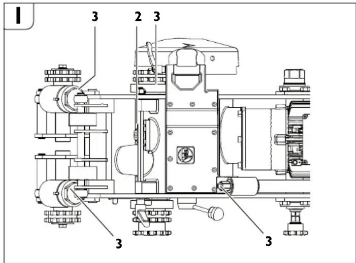
$$ \beta = 8 ^ {\circ} $$
$$ r = 6 m m $$
$$ b = 4 \mathrm {m m} $$
| U-nodóha φoρma, BVCOKOJIeROBaHa ⅦBnAkoPɪ3aJIbHa cTaNl, ΑЛЯ TПУ peáyuktopa: | |||||
| A - AДЯ OБрбкИ BVCOKOJIeROBaHIX cTaNBEx Tpy6 В - AДЯ OБрбкИ HENeRθOBaHIX cTaNBIX a60 YaBvHInx Tpy6 3 MaKc. TOBùNHOJ CTiHOKdo 10 MM i MaKc. DiAmETpOM 1600 MM | |||||
| D B Maca KIльКlICTь | ЗуБцIB | MaKc. ГINБиHA pi3aHЯ | HomeРдя ЗamOBлeHЯ | ||
| (MM) | (MM) | (Kr) | (MM) | ||
| 160 25 2,8 | 40 25 6 35 | 08 089 | 00 7 | ||
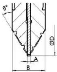
Jahna Jahnzura
TexhiHa DOkymeHTaJia: C. & E. Fein GmbH,
D-73529 Schwabisch Gmund
3axnCT HABKONHbOro cepedOBuA, yTnlaiai.
Ynakobky, Bi npaibobai HeektpoiHcypmEnTa npnaAAnoTpi6Ho ytni3ybaN ekonolirHQ uCTHM cnoCoBom.
IpeoHaOpHnHaHnata HnctpyKm3a eHcNnoTaauHa.
H3noJI3BaHH cHMBOJH, CbKpaueHH H TePMHH.
3a Bawaata chryphoct.
06uynka3aHH3a 6e3onacHOCT.
BHIMAHNE IpOoyetete BCnHn yKa3aHn 3a 6e3oNaChoct, 3a paOTo c MaunHata, 3aNo3HaTe Ce C H3o6paHeHnTa H TeXnHueChte
DAHHN, KOHIO HDABAT C TO3H ENEKPOHNCTPYMENT. Iponyckn npn cna3BaHeto Ha yka3aHaHTa 3a 6eOanHOCTn 3a paOto c MaunHaTa MOrat aa PneAn3BkAt TOKOB YApD, NOKAP n/HIN TeKKn TpABMn.
CbxpaaHbAte BcMHN yHa3aHH 3a 6e3onachOCT H 3a paOta C MaunHata 3a non3BaHe B bDeue.
N3non3bAHnR yka3aHnra 3a 6e0nacpa6oTa TepMH
eneKtpOHCTpyMeHTu cbc 3axpaHaBau Ka6en) n AO akyMnyatopHN
eneKtpOHCTpyMeHTu (6ez 3axpaHaBau Ka6en).
1) Be3onachocHT ha pa60THOTo MACTO
a) NdIbPMAHTE pAOHTO Cn MACTO H NOPE OCBETHO.
Be3NOPAaBkTn HeoCTaBHO TcEBtneHHe MoRt Da cNOMORHa 3a
Bb3HNKBAHETO H TpyO8a 3IOJONyKa.
b) He pa6oTeTe C eneKToHHCTpMaHnTa B cpea C nobHwena OnachOCT OT B3HHBAHe Ha ECHCnNo3Hn, B 0HN3OCT DO NecHO3aNAHn TEuHOCTn, Ra3OBe Hn npaxoo6pa3Hn MaTEPhaHn. IIO BpeMe Ha pa6oTa B eNEKToHHCTpMaHmTe Ce OTeJenNckPn, KOnTO MoRat Da B3PiAmeHn TpaXoo6pa3Hn MaTEPhaHn nn Napn.
c) DpHTe Dea H cTpaHnHH Ha Na Ho 30aNaCHO pa3cToHHe,doKato pa6oHTe C eENTPOHHCTPymEHa. Ako BmHaMeTo Bu 6BaTe OKNoHEo, MoKe Da 3ary6tne KOHTPOna Hd eNeKTPONHCTPymEHa.
2]Be3oNaChOCT npn pa60a C eIeHTpHueChn ToK
a) ΜεncyIbT ha eIeHTPOHCTpyMeTHa TpObBa da e nOxOAnu 3a noI3BaHHHOHTAK. B HnKAbB CnyHae Ce DoIyNcHa N3MeHHe Ha KOHTpyCuHTa Ha uenceLa. KorTo paOtoHE cb cAzHyEne hEeHTpoyeH, He N3noI3BaHTe Aadantep 3a uenceLa. POnI3BaHeTo Ha opnHnHaHn uenceHn KoHTAKn HAmaJIbBa PnCKa OT bB3HnKBaHe Ha TKOK yAp.
b) 368raBaTe OAnHpa H TaTNO Bn Do 3a3eMeHH Tena, Happ. Tpb6h, OTONHTENHH ypeH, neHH N XlaAHHNHN. Korato TnToTO Bn e 3a3eMeHO, PCKBt OT B3BHKNBAHe H TOKOB YApE nO-FONIM.
c) Npnda3baTe eJektpoHHCTpyMeHTa Ch OT dbHn H Bnara. IpoHNKBaHTo Ha BOda B EJekTpOHCTpyMeHTa IOBnBa ONaCHOCTTA OT TOKOB yAp.
d) He H3non3BaIte 3axpaHbAun HA6e 3a cenH, 3a HOHTo ToH e npEDBHN, HAp, 3a Da HOCHTE ENEKTOHNCTPymEtA 3a Ka6ena HnHa 3BaDAHTe UENcEa OT KOHTAKTa. IpeDn3BaHTe Ka6ena OT HarpBaHe, OMACnBaHe, DOnHP Do OCTPH p6OBe HN Do NOdBHNH 3BENA Ha MaHHN. TOpBeEHn Hn YcyKaHn Ka6eni YbeJIuHabat PmCKa OT Bb3HNKBaHe Ha TOKOB yAp.
e) Horato pa6oHTte c eIeHTPOHnCTpyMeHT HABbH, H3non3BaTe cMo yBbHNHTENH Ka6En, NOxOaHs 3a pa6oTa Ha OTHpTO. H3non3BaHeTo HA YbNkTei, PpeHa3HaueH 3a pa6oTa Ha OTKpUTo, HamaJIbaPnCKaOT Bb3HKnBAe Ha TKOKB丫AP.
f) Ano Ce Hanara H3non3BaHTo Ha eEnTePONHCTpyMehTa Bb BnAHHa CpeDa, H3non3BaHe NpeDnaseh NpeHbCBAa 3a yTEHN TOHO. N3non3BaHTo Ha NpeDnaseH NpeKbCBAa 3a yTEHN TOKObe HAMAnra BA onaCHOCTTAOT Bb3HNBAHe HA TOKOB YApd.
3)Be3onaceHnauHHHa pa60Ta
a) bdefe KOHcHTpPAnHH, cIeTe BHNMaTeNHO DeCTBHnTa CN NocTBNaBHe npEpa3JIbHO n pa3yMHO. He hON3BaIte eKTPoHnCTpymTa, Korato Cte yMoepH HIN NOB BnHaHHeTo Ha HApHOTuHBeueCTBa, aKnOxOI HIN yNoBauHnKeapCTBa. EAnH MnPa3ceHoCT npa6oTa c eKTPoHnCTpymEt MOke Da HMa 3a NocLeAChTBHe N3KNIOHTeHIO TeKKn HapaHBaHn.
b) Paobetecnpa3BaHpaOtoHO6nHIO H BHHar c npda3H0UHa. HocHeTo Ha NOxO4JI 3a Np3BAAH enEeKTPoHCTpyMeHT n N3BpWBAHATA DeHcOTN HIN NpeA3Hn CpeACTBa, KaTO AnXaTeHa Macka, 3ApABn PnTHo3aTBopeHN O6yBKn Cbc CTaNen HpaHep, 3aunTHa Kaka Hm YM03aFnyWntEN (ANTNoHn), HamaJIraBa PmCKa OT BB3HnKBAHe Ha TpyOba 3NOPOyKa.
c) H368RaBte onaHocCTTa OT BxNIOUbaHe Ha eEnKTPoHHCTPymeHTa no HEBHHMaHHe. IpEHN Da BxNIOuHTe UeNCeLa B KOHTA NIN Da NOCTABMe 6ATEPHrA, HANTO N pNp INeHAcHHe Ha enKTPoHHCTPymeHTa, Ce YBEpBAHrA, Ye NCKOBnT PpekCBaay e No3NuHa "H3NIOUheo". HocHeTo Ha eENKTPoHHCTPymeHTn C nPbCT BbpXy NcKOBnI PpekCbcaH NIN NO4aBaHeTo HA 3axPaHbAso HAnpeKeHHe, OkATO NcKOBnT PpekCBaay e BKIOUeH, YBeJIuYaba ONaHOCCTTa OT TpyAOBn 3IOnOJNYKn.
d)Ппдддддддддддддддддддддддддддддддддддддддддддддддддддддддддддддддддддддддддддддддддддддддддддддддддддд徳нгнгнгнгнгнгнгнгнгнгнгнгнгнгнгнгнгнгнгнгнгнгнgнgнgнgнgнgнgнgнgнgнgнgнgнgнgнgнgнgнgнgнgнgнgнgнgнgнgнgнgнgнgнgнgнgнgнgнgнgнgнgнgнgнgнgнgнgнgнgнgнgн gngn
e) H36RaBHe HeEeCTeBHeMe NOIOHHe Ha TAnOTo. PaOTeTe B CTa6HnHO NOIOHHe HA TAnOTo H BB BcEH MoHemT NODpaHMaTe PabNOBeHe. Taka 1e MoKeTe Da KOHTpOHnPte eNEKToPHNCTpyMeHa INo-Do6pe N IO-Be3oNaCHO, Ako BB3HNKe HeoVakBaHa CHTyaUN.
f] PaOToTe C noxdoaio 06eHno. He paOToTe C uHpOnn ApExn Hn UypaUeHNHa. DpHKe Hocata N dPexHe C n H aEoIaNo cHbOzAncho PAcSTOrHHe O T ABHHeuC Ce 3BHeA. UwOKeTte ApeXn, YKpaUeHNrA, Ablrnte KcO MoraT Da 6BaAt 3axBaHaTHn yBvNeHuN OT BByrTuCe 3BHeA.
g) Ako e Bb3MOHNO H3NON3BaHETO Ha BbHJHa acnHpaCIOHHa CNCTema, ce yBbpeBAHTe, TRe TA BKNUChEA N FyHNCHOHHa H3npaBO. H3non3BaHTo HAacnPaCIOHHa CNCTema HaMaJIaBA pNCKOBTe, AbJIkaUNCe Ha OTAENLIe Ce npri paBota npaxobe.
h) Do6poto no3HABaHe HA cIeHTPOHHCTpyMeHa BCNEcTBe Ha YecTa paOTo C Hero He e NOSo 3a HAMAnBaHe BA HBMAnHEto NpeHeOpBaHa H MepKHe 3a 6eOnanachOt. EaHO HeBHNMaTeNo HO AeJCTBe MoKe Da NpeAa3BnKa TeKKNa HapAHBaHnna Camo 3a YaChto OT CekyHData.
4) PpHHHBO OTHoWeHHe HbM eEnKtponHCTpyMeHTne
a) He npetobapbaite enehtponhctpymentHa. H3non3baite enehtponhctpymentHte cAmo cb06pa3Ho TRXHOTOpnpedHa3NaueHne. Ile pa6oTHe no-ao6pe n No-6e3oNaCHO, KoraTo n3no3BaTe nOxAoAunie enehtponhctpymentB 3a4aEHHN O T PnO3BOAnTeI Ana3OH Ha HATOBAPBAHe.
b) He nonbae enkpohctpymeHT, HnTo nyckOB npenbcBa e nopehen. EneKtponHCTpymeHT, KOto He moKe Da 6bAe mKnIOuBaH IN BkIOUBAH IIO pIeABnAeHnO TPOIN3BOaNTeRHaAHnE, e ONaCeH Tpr6Ba Da 6bAe PemOHTrpaH.
c)Ппдд КЗьрвateн KaBHTO nДа e DeHOCTH no eNtponHCTpyMeHa, HnP. HAcTpoBAHe, CMAHa Ha paOToEN HnCTHpyMeH, HAKTO H Korato I npH6pTaE, K3NIOuBaTe uecnca To KOHTaHr, pecn. K3BaHJaTe 0tepeHMa, Ako E Bb3MOHNo. Ta3m MpaK PemaxBa OnaCHOCTTA OT 3aDeIeCTBaHe Ha eNekTPOHNCTpyMeHa NO HeBHMaHHe.
d) CbxpahnbaHte eneHTponhctpyMeHTHe Ha MecTa, HbTeTo He Morat da 6DaTdoCTHRHAT O Deua. He DonyChaTe Te Da 6DaTtN3ON3BAHN OT NHa, KOHO He Ca 3Ano3HATc HA qHnHa PaBota C TxAH He Ca npOeyH Te3N HnCTpyKuHH. KOrAto Ca bPcete Ha NeOHNTHNOTpe6HtEN, eNEKTPOHnCTpyMeHTHe MoRrTa Da 6DaTtN3KNIOHTeNo ONaCHn.
e) Nopdbpnahe dope enehtponhhctpymhte cn n ancecoaphte hm. Npobepbaite daa NpobHHHnTE 3BENA yHKNUOHHPat 63yNOpHo, daHn He 3aHNHBAT, daHn HMa CuyneHN HnN NOpehen DeTaN, KOHO HApUwBaBAT HnN H3MeHNTyHKnHTHe aEHTPOHHCTPYMHTA. PpeH da HNON3bATE eNEtPOHHCTpymHTa, ce NORPHHe TNOpehen DeTaNn Da 6bDat pemOHTHPAHn. Mhoro OT npydoBHte 3nONONYk Ce bNkxt Ha HeoOpe NoaBpKaHn eneKTPoHHCTpymEtHu ypeAn.
fI NOIbPMAHTe peMeHUN HCTpyMeTH BNHH Oo6pe 3atoeyHN uHCTN. Oo6pe NOaBpKaHnTE peKeuHN HCTpyMeTH cOcptn Pb6Obe OKa3BaT IO-MAJIKO CbNPOTIBNEHm E BOaRT IIO-NEKO.
g) H3no3BaHte eIeHTPOHHCTPymHTE, DoBbHNHTeHNHE npHCNOcOJIeHH, pa0oTHHe NHCPTPYMeTHN T.H., Cb0p3aHO NHCPTyHcHNE Ha npO3BOJNTeH. pPH TOBA CE c6o6pa3RbAte H c KOHNKpeTHHe paOoTH yCObHn H onepaHH, KHOTo TpOBa DA H3nbHInTe. V3IO3BaHeTO Ha eIeKTPoHHCTPymEHn 3a pa3NIuHr OT ppeABuDeHte OT npO3BOJNTeH. PpINOXeHn NOBIIaBa ONaCHOCCTTA OT Bb3HNKbaHe Ha TpyOBN 3IOIOnyKn.
h) NpIbPnHaTe DpbHHNHe NpbKoXBaTHHe cyxH, NcTm H HeomacneH. Xnb3rBaHte ADbKKn N pbKoXBaTK He No3BOnBaT 6eOJaCnTa pa5Ota N Do6poto KOHTpONHa He eNeKToHNCTpyMeHt PnH B3HNKaBe Ha HeoyakBaHa cHTyAaJn.
5]Ioddbpkahe
a) DonychaHte peMOHTbHa eEnETPOHHCTPymENTHTE Bn da CE h3BbpBa cAmO OT HbAINHOHNPAH CNeuaHnCTH N CAMO C H3NO3BAHETO HA OPHNHAAHNNpe3EBPHN qACTn. To 0To3 NaHnCe rapaHTnpa CBxpaHRABe Ha6eOnaCHOCTTa Ha enETKPOHHCTPymENTHa.
CneuHaHH yHa3aHH 3a 6e3oNaCHOCT npn pa6Ota C MaunHH 3a Φpe3oBaHe Ha Tpb6H.
PnIpyckaHeToB EekCnloaTALna, No BpeMe Ha pa6oTa n npTeTexHueckoto 06cnyKaBaHa Ne MaHInHa3a 3a PpeOBeHa Htpb6n CnA8BaJIte HauHOHJAHHTe HOPMaTHnBH DOKyMehTu 3a 6eOnaHocCT.
Cnza3BaIte 3aKoHOBInTe dIpeKTHINb 3a IpeAna3BaHc ot EKcnIO3m.
OcHpyraBaiTe cA6HnHO 3axBaUaHe Ha o6pa6oTBaHaTApb6a. Hecnna3BaHTo Ha TOBa n3nCKBaHe Moke Da npEaN3BnKa cepno3Hn HapaHbAHn nn CmbPT.
3axpaHbAH C eIeKtpHcEBo Maunnn 3aΦpe3ObaHe Ha Tpb6n (Moden RSG Ex (^**)
3axpaHbauoTo HnpeKeHne Tp8Ba Da CbOTBeTCTBa Ha DaHHNte, NocOeHN 3a MaunHaTa 3a fpe3OBaHe Ha Tpb6n.
3axpaHbAaTaBepra 3a MaunHaTa 3a pe3ObaHe Tp8Ba Da e 3auNTeHa c npEpa3nTe1 20 A.
PeobHO npOBepBaIte 3axpaHbAunna Ka6en n eBENTaHNO non3BaH ydbnKnt!
BknHouBaIte MaunHaTa 3a 4e3ObaHe Ha Tpb6n KbM Ta6Noto Camo KOrato rnaBnHT npeKbCBAe E B NOJKeHne "NkHIOHeo".
Ta6nToC npeKbcBau Tp6Ba HnpeKbChaTO Da e OocTbHNO 3a 06cnyBaunmaHHata.
Pa6ora.
IopdbpHaTe pbKoXBaTKHe N NOBbpxHOCTHe Hm UcHn H63 OMacnBaHe.
Xlb3aBn pbKoXBATKN He NO3bONJIbBAT cNpyPhata pa6Ota C MaINHATA N KOHTpOnIpaHe Ha eNeKTpOHCTpyMeHTA pN B3HNKBaHe Ha HeOaKaBAHc CNYaUH.
Horato H3nbHBAte DeHocTH, npH KOHTO pa60THAT HcTpyMeHt MoHe da nonaDHe HA cKHT NOd NOBbPxHOCTTA npoBOHNn NOd HappeMeHHe, DOnpaHTe eEeTPOHHCTPYMeTA CMO dHO3NpAHnTE pKbXOBATKH. TnPc cbPnPKoCHOBHe nC PPOBDAHKn NOA HanpeKeHHe TO MOKTe a Ce pPeaAe N IO metaHnTE NOBbPxHOCTHa eNEeKTPoHHCTPyMeHTa T OToA Da IpeAn3BnKa TOKOB yAp.
He npetobapbaIte MaunHATA 3a P3eO3BaHn Ha TpboH. H3noon3aBte noXoAun 3a H3bPbBnAHATA deHocT pa0oTHN HcHTpymTeH. C nOaxoAau pa6oTeH HcHTpymEt Ue pa0oTHNe IO-kaECTBHe N IO-CnryPhO.
He 3nnon3BaHte MaunHata 3a dpe3oBaHe Ha Tpb6n, AHO NcchOBHn Npehbcay e nopehen. MaunHa 3a dpe3oBaHe Ha Tpb6n, KOTo H Me OKe Da 6bDE BKNIOUeHa Hn Hn 3KIOUeHa No PneABnDEHnO NT pON3BOAnTeN HauH, e ONaCn H Tpa6Ba D a 6bDe pemOHHTnpaHa.
IpeKbCbaTe 3axpaHbAHeto, npedn da H3BbPWBate HactpoHH NO MaunHATA HIN da 3aMeHrte paOthHn HHCTpymEn. TaN ppeAtnaHa MApka PpeoTbpTaBa HEBOJHOTo BKJIIOUcBA He MAuHNaTA 3a ope3OBaHe Ha Tpb6n.
He DonyuchaiTe C MaunHnata 3a Φpe3oBaHa H TaPbN Da paOToTn IuHa, KOHTo He ca 3aIIO3HaTH C He N KOHTo He ca PpoenH TeN yKa3aHHa. MaunHInTe 3a Φpe3oBaHa Tp6Bn Ca OAnch, Ako ce ON3BAT OT HEONINTH Nua.
Peobho no podbpaHte Maunnata 3a PpeoBahe Ha TpbO. IpopeepbaTe n 3a ebeHTyAnHH ypeHdAnHH, KaTOn H 3a dpyTH PhaTOpH, KOtO MOrat Da BNOaT npBnHOto fHyuHnOHNpaHe. MaunHa, KORTo He E h KpRAnD CbCTOHNHe, TpOBa DA bDe peomthPana ppeh no3BaHe. MHOr OTO 3IonoNyKIne, KOtO 6NuXa MORnA Da 6DaT n3eBerHATn, Ce pnuHnRaB AT OT NIOO NOAeHnMaunHn 3a PpeoBaHa Ha TpbO.
H3no13BaIte MaunHata 3a Ppe3oBaHe Ha Tp6h, DOnbInHTeINHtne npncocOeHHn, paOHTHe HcTpyMeTHn T.H. CbOpa3HO Yka3AnHrA T ToBa pbHOBOCTBO 3a EKnOaTaauH, Hato Ce CbOpa3BAte C KOHNpETHNe paOToHN yCIOBn H3mbNbaHata OpeuaH. H3no13BaHeTo Ha MaunHtne 3a Ppe3oBaHe Ha Tp6h 3a DeHocTH, pa3NlHuOHn OT ppeBnDEHnTE OT pOn3BOAten, Moke Da Ppe43BnKoAonCHn CnTuAun.
CbueCTByBaOnaCHOCT ON nopraBaHe OT OCTPte pb6Obe Ha pa6OTHn HHTCPyEMT. PtmoMOnTHpaHe N AEmoHTpHa He pa6OTTHNHTCPyEMT INON3BaIte NpeAa3nH PbKaBnU.
Onachoct or HapaHbahe
CbIeCTbByBa ONaCHOCT OT INr3rapAne HO T ORePcHn pa6oTeH HnCTpyMeNT. PpN DeMOHTnpaHe Ha pa6oTHnH INHCTpyMeNT NOn3BaTte PpeDnA3Hn PbKaBnU.
Pa6oTeTe c nppea3Hn pbKaBnU.
H3non3baTe caMo pa6OTHn HhCTpyMeHTn c 6e3yIpeuH pEkeu np6oBe.
- PpeAnIOCTaBHe IOUHcTe Te Bana, KaKTo N cHTpOBAuNTe N 3axBauaNIOBBpXHOCTn.
- IocTaBeTe pa60THH INCTpyMeHT C AnCTaHUNOHHN ANCKOBe.
- 3aterheTe raikata 3a 3axbaaHe Ha pa6oTHnHnCTpyMeHT.
BhJIOUbaHe.
Maunha 3a 0pe3oBaHe Ha Tpb6n:
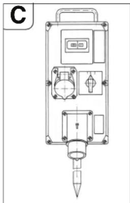
BknIOyeMaHnHaTa 3a φpe3OBaHe Ha Tpb6n c eneKTPnuecko 3aDbNKBaHe npE3 Ta6No C npEkbCBAu, KOEt cbAbpKa CneAHNTe KOMNOHEHTI:
-ΓnaBHe/peBepcBBeH npeKbcBaH
-ПpeAna3eH npeKbcBaY 3a eNeKtpoABnraTeNa
- PteAna3HNO pece 33 nK3nIOuBAHe pIn OtnAaHe HnHa npKepeHneTO
-KynnnyH3n
IaBnHrT npeKbCauCe H3nON3Ba 3a BkIOuBaHe H 3aO6pbUaHe Ha NOCOKaHa BBpTeHe.
PpeAa3HnT PpeKbCba 3a eEnkTpoABnTaTeN n PpeAa3HOTPe OEpa3yBaT eAnmOayn. Pn PpeTOBpBAHe PpeAa3HnT PpeKbCba 3a eEnkTPOaBnTaTeN H3KnIOuBa, PnO TNaaHa He HaPpeKeHHeTo N3KnIOvBa PpeAa3HO To pene, 3a D a PpeAOTBpatn HEKoHTponHaO BKNIOuBaHe Ha MaunHata 3a fpe3oBaHe Ha Tpb6n Pnp
Bb3CTaHOBBAHe Ha HanpeKeHHeTO.
MaunHaTa 3a 4pe3oBaHe Na Tpb6n Ce Ncyka OTHOBO 4pe3 BKNIOUbaHe OT npekcbuca 3a eneKtpoADBirataTeI.
Ta6nTo C npeKbCaHn Tp6Ba Da e pa3nOIOKeHO TaKa, Ye Da e OocTbHNO 3a o6CnyBaaHn MaunHaTa HnpeKbChato.
Maunha 3aΦpe3oBaHe Ha Tpb6n B yacTH4Ho 6e30nachO 3a EHCnIO3HH3IbHHeHHe:
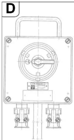
PpeA TabIoTO C npeKbCBAuN 3nON3BaTe OAnbFnHITeEN NcCKOB npeKbCBAu 3a pa6Ota Ha MaINHaTa B cpeA c NOBHeHa ONaCHOCT OT eKnIOHmOT o30a 2.
IyckOBnT npeKbCBA Tpr6Ba Da 6bAe NocTabEH TaKa, yeAa 6bEoCTbEN 3a 0cbcNjXbaunna MaHInHATA BBB BCEKN MOMET.
OnachocOT EKCNIO3M
Ta6nToC npeKcbcauu Tp8Ba Da e nocTaBeHo 3BbH 3OHata 2.
Pa60ta c mawHHata.
Onachoct or HapaHbahe
PbpeHa pa6ota npea3HnT KOxy Tpr6Ba Da e HnblHO 3aTBOpEH 6nokpah!
OnachOCT OT HapaHbAbe OT OXBpauu CTpyKKn
Te Morat Da IpeaN3BnKaT HapaHbHa. BHMaBaIe B 3acTaWeHaTa 30Ha Da HrMa Xopa.
OnachocT onokap OT OXTbbpauu CTpyKKn
BHHMaBaTe B3acTpaaHeHaTa 30Ha Da HrMa JleChO3aJaIIMn PpeMeTn.
Onachoct or HapaHbahe
PnB KKnIOVAHe Ha MaIHHaT3a 3pEzOBAHe HA Tp6Bn CbIeCTyBa ONAOHcT OHT HApAHBaHE OT XxBbpauu ChTuN. BInHar npeA N BKNIOVAHe Ha MaINHataOTCtPaHAABeT OF He pBuHaT aMaHbena.
PpouecHaBKnIOUbaHe
PnMaHHHe 3aΦpe3OBaHe Ha Tp6bC eEnkTPOBnTeAe Tp8Ba Da ce OCHpyu BbpTeHTo Ha pa6OTHnU HcTpymEHT Da e B npAunHaTa NocKa.
Iocokata Ha BbpTeHe MoKe Da 6bAe CMeHeHa Ype3 peBepCnBnI npKcbaH aTa6Noto.

Onachoct ot HapaHbahe
Pn pa6oTea MaunHa cbueCTbYa OAnCHOCT OHTapaHraBaHHrO T BpTaIuNTe ce enEMeHTN. B 3actpaUeHata 30Ha Tpr6Ba Da Ce BNt3a cAmo Pn n3BpbWbAe Ha NaCTPOKn N npn CTporo Cna3BaHe Ha MePKnte 3a 6e3oanCHOCT.
- 13KIOUeTe peAkyToppa 3a noAbaTeHnHOTo ABHXeHne ype3 NoCTa (28).
-BKNIIOHcTe MaunHaTa 3a fpe3oBaHe Ha Tpb6n.
Ocb6o6aTe Nocta (11) H cbyHata MaHbEbaPexe Te BpTnna Ce AHC B Tpb6aTa KONkTo e B3MOxHO n-HaOny. ABn6Oko Bp3aHnT peXeu, AnCK CTaNINHpa npocca Ha p3aHe. - PnI pfe3ObaHe M36pePeTe NO BB3MOXHOCT NO-MANKO Bp83BaHe Ha pa60THN Hc7tpMeHr. O6embTpa3P3BaH MaTePnAn HapactBa C yBEnuHaBe Ha Ab6OvHnHa HbP83BaHe.
BpeTa pa60THHnIHCTPmENT pH6n.3mmno-Abb6oOOTyHXHOTo, nocCe bBpHeTe AO Heo6xoAUMata AB6ouHnHa Bp3aBHe; taKa pa60THHnIHCTPmEe Ce OCB6oKABDa
-Пин nIOnI3BaHе Ha ckana 3a AbI6OuHHa, DonpeTe pa60THMa HHCTpyMeHT O nobBpXHOCTHa Na Tpb6Aata. PaaBnIte HakaTeHata Raika (27) nNoctabe tCpenKaT8) Ha NoIusuO 0. OTHOB zaterHe Me HakaTeHata raika(27). AbN6OHHaTa Ha Bp3BaHae MoKe DA bAe OTHeHa No cKaIaTa.
-ИЗКИЮЧЕ МАШИHAТа 3a ФпeзOBaHе Ha Tpb6n.
CneA TOBa 3axBaHete 3apabo 4pe3 3aTgAre Ha Nocta (11).
-OTHOBO BKNIOUOte MaunHata 3a ope3oBaHe Ha Tpb6n.
Cnocta (28) BknioueTe peAkyTopa 3a noaBaHe.
AkoMOuHOCCTHa eNEKTPoABnIaTeIe eoCTaTbUHa,CTeHaTa Ha Tpb6aTa Tp6Ba Da ce pa3peKe Ha eINH IPOXoA.
-ПОLOЖЕНТрбнМожЕДноДдАТNOВЕмHa pЯЗаHe npeKeшиrt HHTPymeHTMOKEДаСеЗКЛИNH.3ATOBa BKNIOUeHNTeBOKOMNKeTobKaTa KlnHOBe Tp6BaДаCEHa6NBaTBMEXKAnHaTcNEApeKeSHnHHTCnPTyMeHTHa PABHN HnTEpBAH.NBcpeAN CNoBbUeHOnAChOCTOTekCNIOZnNn3N0N3BaIte KlnHOBeTe(63305013002) (RSGEx 1500A/B**) BKIOUeHnB OKOMNKeTobKaTa)ИУК OT MaTepHaJI,КоТTo HE OТДЯн NCKPn.
H36raBnTe npetoBapBaHeTo Ha MaunHaTa 3a fpe3ObaHe Ha Tpb6n.
MaunHata ce npetobapba, ako npn Bp3BaHe Ha BpTtuae ce pa6oTeH HcTpymeHT cKOpocTTHa BaBpTeHe Ha eNEKTPOaBnTaTeHaMaJee 3HaunTeHNo.
-TOBa BOAn CbIoo AO HaMaJIaBAHe Ha IpOu3BOaNTeHOCCTTa Ha p3aHe.
YkpEnBaHte Taeta (OTp3BaHna KpaHa TpbGaTa), 3a Da npedeOtpaTnTe naaHeto My.
PnAe6eNoCTEHn Tpb6n (s>10mm) 3abapbHata yra Tp86Ba aa 6bde ppeoBHa Ha HkONK npoxOa.
IgAkoTo npOtuaHe Ha p3aHcTe ce onpeEeOn ot cneAHte oakTopn: -PiopabHbaHe Ha mAsHata 3a 0pe3oBaHe pN CTapTnpaHTo,
- reomeTpnuHOTo OTKnIOHeHne Ha Tpb6ata OT Kpbf, peCn. OT cINHApnuHa opMa,
- 0KoKo 06pe e 3aToeH pExeunr HnCtpymENT,
TbBpOCT Ha MaTePnAna.
MaunHaTa 3a fpeoBaHe Ha Tpb6n e HacTpoHa TaKa, ye npn Anametpn 300 mm n 600 mm Naanato N kpaar Ha IINHnTe Ha cpea npn6Iin3ntenHO cbbaad. BcneAcTBVe Ha ecUeHTPNiTETa Ha BOeunB aal MapknopOBkata 3a noapabHBaHe (24,BNXTe FnrypaE) e BAHNHa cmo 3a DBA tnoocehn Anametbpa. Ppi No-folemn Anametpn npn Heo6xoAumocT Tp86Ba da ce n3Bbpwn KopeKuia.
06paTeH xoJ ha MaunHH 3a Phpe3ObaHe Ha Tpb6h (RSG Ex (^**)
Onachoct ot zeth!
PpeAn MaHHTa 3a 0e3OBAHe Da 6bAe BbPHATA B HauJIHa N03nIIN,paBOTNHATNCHPTymENT TpRABa 6bAe N3BaDeHOT Cpe3a,3a Da ce N36erHe NOBPeKdAHe HA NCHPTymENTa H aPe4yKTopa.
- 13KIOUeTe peyKTopa 3a noaBaTeHHOTo ABHXeHne ype3 nocTa (28).
- Ocbo6oAeTe nocTa (11).
-Ⅰ3BaTe pa6oTHnHnHcTpymeHT. - NocTaBeTe rnaBHHra/peBepcHbHn npeKbcBaB B no3nua «0» (n3KnIOyeHo).
-IOCTaBeTe peBepcNBHnI npEkbcbay B no3nua 3a o6paTeH xoA.
-3aterheTe nocTa (11).
CnocTa (28) BknioueTe peAkyTopa 3a noaBaHe.
Maunnata 3a Ppe3oBaHe TpbH He MoMe da peme npn o6pAHHXoI
Yka3aHaHa 3a OxlaHaDaHe H Cma3BaHe.
Onachoct ot ets!
IIO Bpeme Ha p3aHae pa6oTHnT HnCTpyMeH Tpr6Ba Da 6bde OxnaKaDaH n CM3aBH. Ipn HeAOCTaBtHo OXnAaXaDaHe n CM3BaHe MoKe Da ce NOnyHn nonenBaHe Ha cTpyKKn. TOBA MoKe Da npeAn3BnKa ChynBaHe Ha pa6oTHnHa nHCTpyMeH.
Cn3BaIe yka3aHHa Ta HPOH3BOHTeHa No3BaHHpaOteH HhCTpyMeHT
- Tpb6n OT CNB yuryh Tp86ba Da ce pekka BHHar 6e oxnaaDaa TeHocT.
Pn p3aHe Ha Tp6bO t HeIerHpaHa CTOMaHa OXnAaAte UnpkyIpyHnA Dnck,pecn.Φpe3epa cbcanyHeHa BOa.
HactpoBaHe Ha ToUHOCTa Ha XOJa.
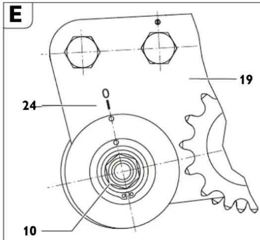
Pa3BnTe raKaTa (15, BnKTe phrypa A) SW 46.
3aBpTeTe oCTa (10) cnPmaKanaka (19).
-3aterHeTe raKaTa (15).
Upe3 3abbpTaHe Ha ocTa (10) No NocOKa Ha YacOBHNKOBaTa CTePnKa (No NocOKa Ha pa6OTTHN HAHTPYMEHT pa6OTTHN HHTPYMEHT CE OTMeCTBa HAARCHO (nORneHaTO NO NOCOKa Ha NpeMeCTBaHETo Ha MaUNHATA 3a Fpe3ObaHe).
Pp3 3abbpTaHe Ha cTbOpaTHo Ha YacOBHNKOBaTa CTePnKa pa6OTTHN HAHTPYMEHT CE OTMeCTBa HANBO.
Dobabhe Ha 3Bena Ha Bephrata.
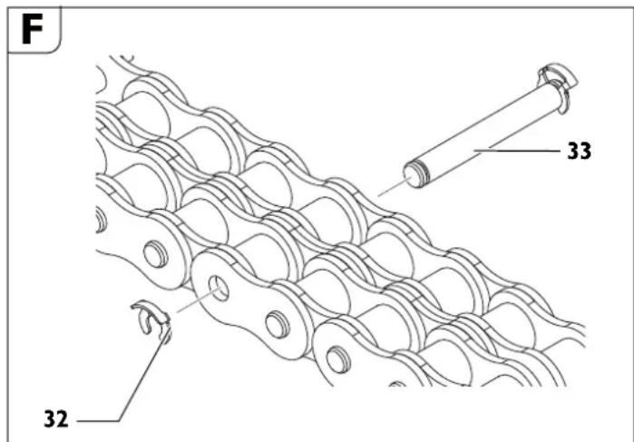

Oncycka ce 06abHrTo Ha 3BeHa Ha BepnraTa cAmo Ha IpeBnAeHnte 3a
IeNTa NsNNI.
CbaTe 3erep-wai6ata (32).
-13BaTeUHΦTa(33).
- NocTaBeTe KeHaHHa 6poB BepnXHH 3BeHa.
-BepnKHN 3eHa c pa3JInuHa abJIKNHa ca BKJIOyeHb BOKOMPNIeKTOBkata Ha MaJINHATA.
-BkapaTe uHΦTa (33).
- NocTaBeTe HOBa 3erep-uaa6a (32).
3aKpenBaHe Ha MaWHHata 3a φpe3ObaHe Ha Tpb6H.
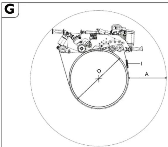
«A» Heo6xOaHMo pa6oTH OpoCTpaHCTBO npn NO-ROJMa ABN6OuHa Ha Cpe3a.
«D» BBHHeH AnameTbp Ha Tpb6aTa
《》6poBepnKHH3eHa npnAnameTpbaT«D
RSG Ex 1500 A/B
| позию Ha octa 3a преемechтвае Ha MaшинаТа | D [mm] [mm] [mm] [mm] | A | H Дылжинha Ha Веригата Ha стара | обся O Дылжинha Ha Веригата | i* 6 |
| 1 250 | 400 | 1427 | 2854 | 5 | |
| 300 | 392 | 1525 | 3050 | 5 | |
| 350 | 384 | 1632 | 3264 | 6 | |
| 400 | 378 | 1744 | 3488 | 6 | |
| 2 | 400 | 381 | 1782 | 3564 | 6 |
| 450 | 375 | 1898 | 3796 | 7 | |
| 500 | 369 | 2019 | 4038 | 7 | |
| 550 | 364 | 2144 | 4288 | 7 | |
| 600 | 360 | 2273 | 4546 | 8 | |
| 3 | 600 | 362 | 2302 | 4604 | 8 |
| 650 | 357 | 2433 | 4866 | 8 | |
| 700 | 352 | 2566 | 5132 | 9 | |
| 750 | 348 | 2702 | 5404 | 9 | |
| 800 | 344 | 2840 | 5680 | 10 | |
| 850 | 340 | 2862 | 5724 | 10 | |
| 900 | 337 | 3001 | 6002 | 10 | |
| 4 | 900 | 348 | 3142 | 6284 | 10 |
| 950 | 345 | 3284 | 6568 | 11 | |
| 1000 | 342 | 3428 | 6856 | 11 | |
| 1050 | 340 | 3464 | 6928 | 11 | |
| 1100 | 337 | 3607 | 7214 | 12 | |
| 1150 | 335 | 3751 | 7502 | 12 | |
| 1200 | 333 | 3896 | 7792 | 13 | |
| 1300 | 331 | 4062 | 8124 | 13 | |
| 1400 | 329 | 4338 | 8676 | 14 | |
| 1500 | 328 | 4355 | 8710 | 14 | |
| *Катуложен Homep 3 02 31 013 02 7, сбостаяц ce ot 10 Всрочи Зева с Дылжина по 635 mm. | |||||
RSG Ex 18 A/B
| позишия на оста за п扼мec'tва到时候 на машинната | D [mm] [mm] [mm] [mm] | A | H Дылжина на верногата настара | обся о Дылжина на верногата | I* |
| 1 250 | 587 | 1427 | 2854 | 5 | |
| 300 | 576 | 1525 | 3050 | 5 | |
| 350 | 564 | 1632 | 3264 | 6 | |
| 400 | 553 | 1744 | 3488 | 6 | |
| 2 | 400 | 522 | 1782 | 3564 | 6 |
| 450 | 511 | 1898 | 3796 | 7 | |
| 500 | 501 | 2019 | 4038 | 7 | |
| 550 | 492 | 2144 | 4288 | 7 | |
| 600 | 483 | 2273 | 4546 | 8 | |
| 3 | 600 | 453 | 2302 | 4604 | 8 |
| 650 | 445 | 2433 | 4866 | 8 | |
| 700 | 437 | 2566 | 5132 | 9 | |
| 750 | 429 | 2702 | 5404 | 9 | |
| 800 | 422 | 2840 | 5680 | 10 | |
| 4 | 800 | 396 | 2862 | 5724 | 10 |
| 850 | 393 | 3001 | 6002 | 10 | |
| 900 | 390 | 3142 | 6284 | 10 | |
| 950 | 386 | 3284 | 6568 | 11 | |
| 1000 | 383 | 3428 | 6856 | 11 | |
| 5 | 1 | 3900 | 3464 0 | 6928 0 | 11 |
| 1050 | 387 | 3607 | 7214 | 12 | |
| 1100 | 385 | 3751 | 7502 | 12 | |
| 1150 | 382 | 3896 | 7792 | 13 | |
| 1200 | 379 | 4062 | 8124 | 13 | |
| 1300 | 374 | 4338 | 8676 | 14 |
| 6 1300 | 387 | 4355 | 8710 | 14 | ||
| 1400 | 382 | 4651 | 9302 | 15 | ||
| 1500 | 378 | 4950 | 9900 | 16 | ||
| 1600 | 373 | 5250 | 10500 | 17 | ||
| 1700 | 369 | 5553 | 11106 | 18 | ||
| 1800 | 366 | 5857 | 11714 | 19 | ||
| x | d900 | A362 | 6162 | M | 12324 | 20 |
| 2000 | 359 | 6468 | 12936 | 21 | ||
| 2100 | 356 | 6775 | 13550 | 22 | ||
| 2200 | 353 | 7083 | 14166 | 23 | ||
| 2300 | 350 | 7391 | 14782 | 24 | ||
| 2400 | 348 | 7700 | 15400 | 25 | ||
| 2500 | 346 | 8009 | 16018 | 26 | ||
| 2600 | 343 | 8319 | 16638 | 27 | ||
| 2700 | 341 | 8629 | 17258 | 28 | ||
| 2800 | 339 | 8940 | 17880 | 29 | ||
| 2900 | 337 | 9251 | 18502 | 30 | ||
| 3000 | 335 | 9562 | 19124 | 31 | ||
| *Katanojen Homep 3 02 31 013 02 7, cbyctoju, ce ot 10 bervjxhi 3veha c | ||||||
3a nocttnahe Ha onTmamnHO oBtaHe Ha BepHrata, MoKe da 6bDat n3non3BaHH npnoxkeHBe Bkyapa c HnCTpyMeHTn NOOBn 3eHa c abnKHa 31,75 mm. PnMep:
PnHAnameTbpHa Tpb6ata D=400mm ca Heo6xoAMMn 6 BepnxHH cerMeHTa (KataJIOKeH HOMep 302 31 013 027).
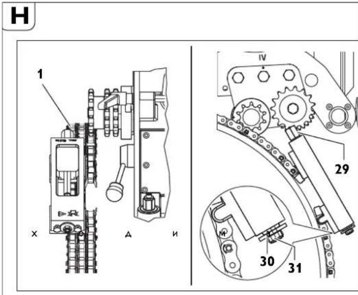
Bodehe no hampablaBaauaTae Bepra
Cnno6e TaBnHnHaTa Ha Bepurata CbTnacHOaHHte B TaBnUata 3a NoCTnraHe Ha ONTMnHo O6TnraHe Ha Bepurata, MoKe Da 6bDat N3NON3BaHN npnNoKeHnTe B kyapapa c HnCTpyMeHTN nONOBH 3BeHa C aBnKnHa 31,75 mm.
AbNxHa Ha BOeMaTa Bepura
| Даметр На Трьбараза | Дыжин а На Веригараза | Верхин семени | ||
| [mm] [mm] | 635 mm 63 | 5 mm | 31 | 75 mm |
| 250 | 710 | 1 | 1 | 1 |
| 300 | 870 | 1 | 4 | 0 |
| 350 | 1030 | 1 | 6 | 1 |
| 400 | 1190 | 1 | 9 | 0 |
| 450 | 1344 | 2 | 1 | 1 |
| 500 | 1500 | 2 | 4 | 0 |
| 550 | 1660 | 2 | 6 | 1 |
| 600 | 1809 | 2 | 8 | 1 |
| 650 | 1970 | 3 | 1 | 1 |
| 700 | 2130 | 3 | 4 | 0 |
| 750 | 2290 | 3 | 6 | 1 |
| 800 | 2440 | 3 | 8 | 1 |
| 850 | 2600 | 4 | 1 | 0 |
| 900 2760 4 | 4 0 | |||
| 950 2921 4 | 6 0 | |||
| 1000 3079 4 | 8 1 | |||
| 1100 3397 5 | 3 1 | |||
| 1200 3714 5 | 8 1 | |||
| 1300 4032 6 | 3 1 | |||
| 1400 4330 6 | 8 1 | |||
| 1500 4640 7 | 3 1 | |||
KaTaoJxeh Homep 30231034010(1=635mm)
KataNoxH Homep 30231036010(1=63,5mm)
KaTAnIOxH HOMep 30231035010(1=31,7mm)
3axbaheTe BOeDaTcBeBnra KbM O6TeeraHa eA eINOT ABtA BePnKHN cermHc C uNHT N 3eep-uaH6a.
- PpekapaTe r noA DBeTe BepnKHN KOIeNa 3a BODeuata Bepura (hrypa H).
3axbaHene Cbo6oAnn KaPn Ha 3aDbNkBaUdTa Bepira KbM ObTeRa C uHΦT n 3erep-ua6a.
Onbhe nO tb6ata BoAeata Bepra Ype3 3abptHe Ha wecctoehHHa 6ont Ha o6terapa (2).
Pdaphe BOeepaTa BepHa pa3cTOnHne 10 mm (uHHT Ha 3aBnBbAaTa BepHa Oo HHT Ha BOeepaTa BepHa) npObepeTe paoTHno HA TpN MeCTa.
3aterHete oBTeHa Ha Bepnata Upe3 uCCTOCTEHn8 60NT (29) AOKATO 5n6ata (30) Oonpe Do Kopnyca Ha o6Te4a (Anna3oH Ha o6Tarahe npn6n. 50 mm). (Makc. MOMeHT Ha 3atrahe 50 Nm)


BHHMaHHe, onachOcT or 3Jiononya!
B HnkaKbB CnyaH He 3aBpTaTte TpTe OcnpyTeHH
BnHTa (31) Ha yenoto. (BnKTe fHypya H)
3aHIOHTENHH DeHOCTH CNEBcAHO non3BaHe.
-VAbaTe pa6oTHnHnCTpyMeHT.
-13KIOeTe MaunHaTa 3a φpe3ObaHe Ha Tpb6n.
- DemoHTnpaTe paOTHnHnHCTpyMeHT.
-0Cbo6oTeMaunHaTa3aΦpe3ObaHe Ha Tpb6n.
CbxpaaHbAe Ha MaunHata 3a 0pe30BaHe Ha TpbH.
- Ppea3eTe OT Kopo3nBbHnHTe MeTaHn DeTaN.
-CbXpaHbAaTeMaunHaTa3aΦpe3OBaHeHa Tpb6nHa cyxO MCTo.
NoabpHaHe npemOnr.
3a noDabpHaHe H pEmOHr.
Mon, npn Heo6xOAnMoCT O T peMOHT Ha eNekTPOINHCTpyMeHTn I
OnbIHNTeHN pnpCnoc6bnHeHn HA FEIN ce 6pbuaaTe KbM OTOpH3npAHn
cepBnHn HpBoUc. AkTyAaHn aApeCe HamePte B INHTepHET Ha aApec
www.fein.com.
AkyaIeH cInbcK c pe3epBHN qactn 3a To3n eJektpOnHcTpymeHT MoXeTe aHaMepeT B HHTepHET Ha aPec www.fein.com.
13no3BaTe caMo opnHaHnH pe3epBHN acTH.
Ipn HeoXOHNMOCT MOHETe CAMN da 3aMeHHTe CnEHNTE EeEMENT: Pa6oTHIN HCTpymEnTH, pbKoXBaTKN, BeprA, BepNXH 3BeHa
Anycka ce mAluHaTa da cea6oTn cAmO aK eB TeXHueckn 6e3yKOpHo cbToHHe. H3OceHN MIO PBpeAeHN GaoTHN HcTpyMeHTN KOMHOENTn TpR6Ba 7a 6Daat 3ameAHn He3a6ABHO.
OnachOCT or HapaHnBaHe
BCJIeAChTBHe HbONHO BKnIOyBaHe.
PpeHn3BpWbAHe Ha KaKBHTO n Da e DeHocTHn MoaHnHaTa 3a
Φe3OBAhe Ha Tpb6n H3KnIOuBaTe UeIcPeNa OT KOHTaTla!
06uynka3aHn
Onycka ce DeHocTH NO NOAaPbXka Ha MaunHaTa Da ce H3BbPWBat cmo OT 06yueHH KBaHnHnupanH texHnU.
IodAbpKaHeTo Ha MaunHaTa ce cbCTOn IaBHO OT:
BbHsHo NocCTBaHe Ha MaunHaTa 3a fpe3oBaHe Ha Tpb6n Hn Ba Bepurnte.
BbHweH orneHa MaunHaTa 3a pe3ObaHe Ha Tpb6n.
- CmHa Ha MacnTa Ha peAkykTopHe.
Cma3BaHe Ha 3aBnKBaUNTe pe36n IN BepuNTe.
Cma3BaHe Ha BOaYnTe Ha BaIOBeTe B MOyInTe 3a 3axBaAnHe n 3a 3aBnKbHe.
IIOAmehnTe Ta6eKnTe n ppeAynpeAnTeHNHe yKa3aHnHa eNEKTPOHnCTpyMeHTa
BcHn CbCTaBH N KOMNoEHTH CbOTBeTCTBaT Ha AnPeKTHNte HA FDA (Food and Drug Administration) Ha Deutsches Arzneibuch (DAB) BbB BaHAnHOTo My KbM MOMHTA n3dAHne.
IpenapaTbT MoKe Da 6bAe AOCTABEH OT:
CmaBaA npenapat BIOCUT 3000 3a TemnepaTpyn 日 ^ C
1L-32132039000
5L-32132040000
Cma3Baau npenapat yctoynuHa ctya 3a Tempepatypn DO-25°C:
1L-32132042000
5L-32132043000
PnB aHHTn c63xpaHbAe C TPha3eH ToK RSG Ex (^**) 3a Da MoKe Da ce 3nONI3Ba PnCIOOC6NeHHeTo 3a OxNaxKaHEn CMA3BaHe CbCrCTeH BB3Ay, e Heo6XoAM KomnpecOp FEIN, KaTANOKeH OHomep 92601023023cE6nT np6n.130 130 1/min.
Pe3epBHH qactn.
Akyane cncbck pe3epBn yactm MOKeTe a HamepTe B INHTepHET Ha aDpec www.fein.com.
Deknapaun 3a CbOTBETCTBHe.
Deknapaunrata CE Baxn cmo 3a CtpaHn OT Ebponeckn cyb03 n EFTA
(EBpOeKcata aocuaaia 3a CBO6oHa TbproBn) n cAmo 3a IPOAkyTN, npEHa3NaueHn 3a Na3apnte B EC nn EFTA.
INMaFEINrapaHTnpaCnblNaOTROBOPHOCT,yeTo3N npOyKT cBoTBcTBAHa BAnHnHTe HOpMaTHNBHOKOMEHTN,NOOCHeHNA NOCNEHATA CTPaHnHa ToBa PbKOBOACTBO 3a EKCNIOATauHA.
Texnuecka dokymentaun npn: C. & E. Fein GmbH, D-73529 Schwabisch Gmund
Ona3BaHe Ha OKoHata cpea, opakyBahe.
OnakOBKNTe, n3e3NIte OT yNtOpe6a enkTPOHCTpyMeHTn AOnbJIHNTeHH npncocobHeHH TpaBa da ce paeBaT 3a OON3OTBOPraBe Ha cbAbpKaunTe CE TB XyCPOBHNH.
Uldised ohutusjuhised.
ATAHELEPANU
Eeltoed enne toru tootlemist
Tipas RSG Ex 1500 A () RSG Ex 18 A ()
RSG Ex 1500 B () RSG Ex 18 B (*)
Matmenys:
-
Masé (m) 80 kg 80 kg
-
Maks. Jrankio 220 mm 220 mm
-
IIgismaks. 974 mm 1088 mm
-Aukstismaks. 334 mm 334 mm
-
Plotis max. 450 mm 431 mm
-
B1 371 mm 371 mm
-
B_2 201 mm 201 mm
-
B3 791 mm 991 mm
Vamzdziu frezavimo masin y paskirtis.
$$ \beta = 8 ^ {\circ} $$
$$ r = 6 \mathrm {m m} $$
$$ b = 4 m m $$
Padeves icerice (attels A)
Uzuriet caurules uzgiezn (17) arejo virsmu tiru no netirumiem un rusas un vienmer nedaudz ieeloojiet to.
- Mainot parnesumkarbas ellu, notiriet un iellojiet kustigo vitni.
Demontaza
lzskruvejiet cilindrisko skruvi (8).
- Izvelciet cilindrisko skruvi (5) no parsega.
- Pec tam ar rokas kloki atskruvejiet padeves ierici no caurules uzgriezn.
- Notiriet un ieIoojet vitnotas das (skatiet sadau Smerviela un elofoanas plans:
- Nomainiet bojatos stikla tiriitaja bredzenus.
Montaža
Montaiza tiek veikta preteja seciba. Montazas laika nebojajiet stikla tirita
gredzenus!
Spriegotajierice
Izvairieties no vitnu uz cilpskruvem netirumiem (3, I att.) atsperkausa. Ja neplegclesams, notirietun leiljolet vitnes.
Smerviela un elosanas plans
$$ \beta = 8 ^ {\circ} $$
$$ r = 6 \mathrm {m m} $$
$$ b = 4 m m $$
5 V a r s 7 0 b
U forma, HSS, parnesumkarbas tipam:
| A, B - têrauda caurúu apsträdel, augsta limena legëtsB - nelenëgëta têrauda un ñuguna caurúu apsträdel lidz maks. sieniŋu biezumam10 mm un maks. 1600 mm diametram | |||||
| D | B | Svars | Zobuskaits | maksimālaisgriësanasdžilums | Pasūtijuma numurs |
| (mm) | (mm) | (kg) (mm) | |||
| 160 | 25 | 2,8 | 40 | 25 | 6 35 08 089 00 7 |

| Blokveida frēzësanas iekärtá, HSS, pãrnesumkãrbas tipam: | ||||||
| A, B - têrauda cauru òapsträdel, augsta limena legëtesB - neleëgëta têrauda un Čuguna cauru òapsträdel lidz maks. sieniŋu biezumam10 mm un maks. 1600 mm diametram | ||||||
| D | B | Svars | Zobu skaits | β | maksimãlais grieësanas džilums | Pasūtījuma numurs |
| (mm) | (mm) | (kg) | (°) | (mm) | ||
| 154 | 30,5 | 2,5 | 32 | 30 | 25 | 6 35 08 099 02 0 |
Kedes posms
$$ \beta = 8 ^ {\circ} $$
$$ r = 6 \mathrm {m m} $$
$$ b = 4 \mathrm {m m} $$
China RoHS Status Certificate
中国RoHS认证概况
Table of Toxic and Hazardous Substances/Elements and their Content
as required by China's Management Methods for Controlling Pollution by Electronic Information Products
有毒有害物质/成分及其含量表
$$ \beta = 8 ^ {\circ} $$
$$ r = 6 \mathrm {m m} $$
$$ b = 4 \mathrm {m m} $$
U-型,高速鋼,針對傳動裝置類型:
a)對藥增樂則藥贝贝已玉皂藥歸藥士,糟藥贈桑菊記伊者
b)云皂皂异,云之在云皂皂孕习如云皂皂习云皂皂习云皂皂习云皂皂习云皂皂习云皂皂习云皂皂习云皂皂习云皂皂习云皂皂习云皂皂习云皂皂习云皂皂习云皂皂习云皂皂习云皂皂习云皂皂习云皂皂习云皂皂习云皂皂习云皂皂习云皂皂习云皂皂习云皂皂习云皂皂习云皂皂
c)国中子青水青歌建,子青云云云云云云云云云云云云云云云云云云云云云云云云云云云云云云云云云云云云云云云云云云云云云云云云云云云云云云云云云云云云云云云云云云云云云云云云云云云云云云云云云云云
$$ \beta = 8 ^ {\circ} $$
$$ r = 6 \mathrm {m m} $$
$$ b = 4 \mathrm {m m} $$
- 1
1 - 100mm-20°C @ 40°C
-
mnnnne nnnn
EC Directive 94/9EC ATEX (amwneanngnll)
Tusunwnuonnne FeIN uRSG Ex (^**)
d) ououououououououououououououououououououououououououououououououououou
e) nndnntnnnnaaennnnnneannnnnnnnnnnnnnnnnnnnnnnnnnnnnnnnnnnnnnnnnnnnnnnnnnnnnnnnnnnnnnnnnnnnnnnnnnnnnnnnnnnnnnnnnnnnnnnnnnnnnnnnnnnnnnnnnnnnnnnnnnnnnnnnn nn
mnnnnaeannnnnneennnnnnnnnnnnnnnnnnnnnnnnnnnnnnnnnnnnnnnnnnnnnnnnnnnnnnnnnnnnnnnnnnnnnnnnnnnnnnnnnnnnnnnnnnnnnnnnnnnnnnnnnnnnnnnnnnnnnnnnnnnnnnnnnnnnnnnnnnnnn
g) nnnnne nnnnnnnnnnnnnnnnnnnnnnnnnnnnnnnnnnnnnnnnnnnnnnnnnnnnnnnnnnnnnnnnnnnnnnnnnnnnnnnnnnnnnnnnnnnnnnnnnnnnnnnnnnnnnnnnnnnnnnnnnnnnnnnnnnnnnnn
HSS HSS HSS HSS HSS HSS HSS HSS HSS HSS HSS HSS HSS HSS HSS HSS HSS HSS HSS HSS HSS HSS HSS HSS HSS HSS HSS HSS HSS HSS HSS HSS HSS HSS HSS HSS HSS HSS HSS HSS HSS HSS HSS HSS HSS HSS HSS HSS HSS HSS HSS
- 1000000000000000000000000000000000000000000000000000000000000000000000
- 120 (21) 111111111111111111111111111111111111
n 28
wunwnnnnne nnnnnn nn nnnnnnnnnnnnnnnnnnnnnnnnnnnnnnnnnnnnnnnnnnnnnnnnnnnnnnnnnnnnnnnnnnnnnnnnnnnnnnnnnnnnnnnnnnnnnnnnnnnnnnnnnnnnnnnnnnnnnnnnnnnnnnnnnnnnnnnnnn nn nannn nn nannn nn nannn nn nannn nn nannn nn nannn nn nannn nn nannn nn nannn nn nannn nn nannn nn nannn nn nannn nn nannn nn nannn nn nannn nn nannn nn nannn nn nannn nn nannn nn nannn nn nannn nn nannn nn nannn nn nannn nn nennn nn nannn nn nannn nn nannn nn nannn nn nannn nn nannn nn nannn nn nannn nn nannn nn nannn nn nannn nn nannn nn nannn nn nannn nn nannn nn nannn nn nannn nn nannn nn nannn nn nannn nn nannn nn nannn nn nannn nn nannn nn narnn nn
- mssuunnnnnaaennnnnne nnnn (10) mnnnnnnnnnnnnnnnnnnnnnnnnnnnnnnnnnnnnnnnnnnnnnnnnnnnnnnnnnnnnnnnnnnnnnnnnnnnnnnnnnnnnnnnnnnnnnnnnnnnnnnnnnnnnnnnnnnnnnnnnnnnnnn
y
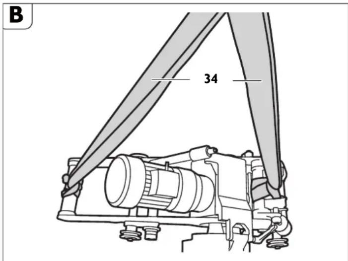
(34)
nouuun
1
0
y d aannnnaaannnn
wouuunnueanuunnnnunnuunnnnnnnnnnnnnnnnnnnnnnnnnnnnnnnnnnnnnnnnnnnnnnnnnnnnnnnnnnnnnnnnnnnnnnnnnnnnnnnnnnnnnnnnnnnnnnn
- 500
aennnnnnaeannnnne aen nnnnnnnnnnne annnnnne ane
aannnnnne
yueyueyue yuyue yuyue yuyue yuyue yuyue yuyue yuyue yuyue yuyue yuyue yuyue yuyue yuyue yuyue yuyue yuyue yuyue yuyue yuyue yuyue yuyue yuyue yuyue yuyue yuyue yuyue yuyue yuyue yuyue yuyue yuyue yuyue yuyue
muaon 0°C:
-BIOcut1L-32132039000
BIOCUT 5L-32132040000
25°C:
-mnau 1L-32132042000
5L-32132043000
nna (nnnuuA)
- 111
anunnnnne (18) nna nileu (7) nnae (nuane) - 00000000000000000000000000000000000000000000000000000
nnaaunnnnnaanennnnnnnnnnnnnnnnnnn (4)
-(g)
RSG Ex 1500 A/B (^**)
| P | D [###][###] | |
| I 250 - 400 9.8 | 15.7 | |
| II 400 - 600 15.7 | - 23.6 | |
| III 600 - 900 23 | 6 - 35.3 | |
| IV 900 - 1500 3 | 5.3 - 58.9 |
RSG Ex 18 A/B (^**)
| P | D [mm] [mm] | |
| I 250 - 400 9.6 | 15.7 | |
| II 400 - 600 15.7 | - 23.6 | |
| III 600 - 800 23.6 | 6 - 31.5 | |
| IV 800 - 1000 31.5 | 1.5 - 39.4 | |
| V 1000 - 1300 39.4 | - 51.2 | |
| VI | 1300 - 3000 | 51.2 - 118.1 |
P:
D:duinuaaannn
- 1000000000000000000000000000000000000000000000000000
A
nnaaannnnnnaananaananaananaananaananaananaananaananaananaananaananaananaananaananaananaananaananaananaananaananaananaananaananaananaananaananaananaananaananaananaananaananaananaananaananaananaananaananaananaananaananaananaananaananaananaananaananaananaananaananaanaraannaa
1 1
10 10
-
nunnnnnae
- nnnnneannnnnneennn nnrnnnnnnnnnnnnnnnnnnnnnnnnnnnnnnnnnnnnnnnnnnnnnnnnnnnnnnnnnnnnnnnnnnnnnnnnnnnnnnnnnnnnnnnnnnnnnnnnnnnnnnnnnnnnnnnnnnnn
aonnoanana aanaeauane 1111111111111111111111111111111 - 10010000000000000000000000000000000000000000000000000000000000000000
ananaananaananaan (30217216004)aaananaananaananaan (42634020005)
nunnnnnnnnnnnnnnnnnnnnnnnnnnnnnnnnnnnnnnnnnnnnnnnnnnnnnnnnnnnnnnnnnnnnnnnnnnnnnnnnnnnnnnnnnnnnnnnnnnnnnnnnnnnnnnnnnnnnnnn
- 1
nuiuunnaunnuunuaan (23 nwnnnn A) hnoonne - 4
D
oannnnaa
n
A
aennnnnne nnnnnnnnnnnnnnnnnnnnnnnnnnn
A
aannnnnnaanennnnnnnnnnnnnnnnnnnnnnnnnnnnnnnnnnnnnnnnnnnnnnnnnnnnnnnnnnnnnnnnnnnnnnnnnnnnnnnnnnnnnnnnnnnnnnnnnnnnnnnnnnnn
A
aannnnnnaeennnnne aennnnne ennnnne
Tnntnnnnnnnnnnnnnnnnnn
nunnnnnae nannnne nnnnnnne annnnnnnnnnnnnnn
-
m
mno:
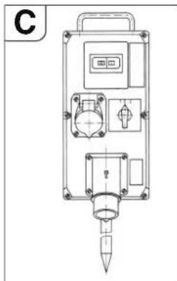
nnaeannnnneennnnnne (line side) nnnnnnnnnnnnnnnnnnnnnnnnnnnnnnnnnnnnnnnnnnnnnnnnnnnnnnnnnnnnnnnnnnnnnnnnnnnnnnnnnnnnnnnnnnnnnnnnnnnnnnnnnnnnnnnnnnnnnnnnnnnnnnnnn
nannnnnnnnnnnnn nnnnnnnnnnnnnnnnnnnnnnnnnnnnnnnnnnnnnnnnnnnnnnnnnnnnnnnnnnnnnnnnnnnnnnnnnnnnnnnnnnnnnnnnnnnnnnnnnnnnnnnnnnnnnnnnnnnnnnnnnnnnnnnn nn nannnnaaannnnaanennn aannnnaanannnnaanannn anannnnaanannnnaanannn annn nannnnaanannnnaanannn nannnnaanannnnaanannn nannnnaanannnnaanannn nannnnaanannnnaanannn nannnnaanannnnaanannn nannnnaanannnnaanannn nannnnaanannnnaanannn nannnnaanannnnaanannn nannnnaanannnnaanann nannnnaanannnnaanann
aannnnnnaanennnnnnnnnnnnnnnnnnnnnnnnnnnnnnnnnnnnnnnnnnnnnnnnnnnnnnnnnnnnnnnnnnnnnnnnnnnnnnnnnnnnnnnnnnnnnnnnnnnnnnnnnn
mnnnnnnaaannnnnnnnnnnnnnnnnnnnnnnnnnnnnnnnnnnnnnnnnnnnnnnnnnnnnnnnnnnnnnnnnnnnnnnnnnnnnnnnnnnnnnnnnnnnnnnnnnnn
nannnnnnnnnnnnnnnnnnnnnnnnnnnnnnnnnnnnnnnnnnnnnnnnnnnnnnnnnnnnnnnnnnnnnnnnnnnnnnnnnnnnnnnnnnnnnnnnnnnnnnnnnnnn
nnaunnnnnnnnnnnn
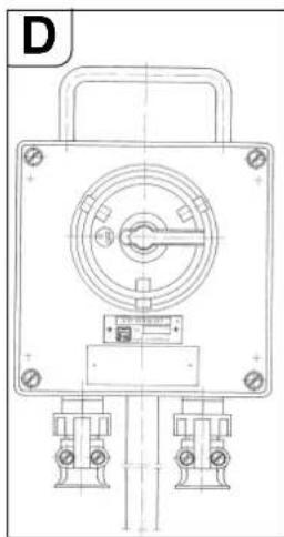
nannnnnnnnnnnnnnnnnnnnnnnnnnnnnnnnnnnnnnnnnnnnnnnnnnnnnnnnnnnnnnnnnnnnnnnnnnnnnnnnnnnnnnnnnnnnnnnnnnnnnnnnnnnnnnnnnnnnnnnnnnnnnnnnnnnnnnnnnnnnnnn nn nannnnaaannn

aannnnnnae
mua
国
aennnnnne nnnnnnnnnnnnnnnnnnnnnnnnnnnnnnnnnnnnnnnnnnnnnnnnnnnnnnnnnnnnnnnnnnnnnnnnnnnnnnnnnnnnnnnnnnnnnnnnnnn
A
aannnnnnaanrnnnnae nnnnnnne aennnnnne
aannnnnnaanennnnn nnnnnnnnnnnnnnnnnnnnnnnnnnnnnnnnnnnnnnnnnnnnnnnnnnnnnnnnnnnnnnnnnnnnnnnnnnnnnnnnnnnnnnnnnnnnnnnnnnnnnnnnnnnnnnnnnnn
A
aennnnnne nannnnnnae aen ane ae enanee
yannnnn
unununununununununununununununununununununununununununununununununununununununun
国
nnnnnnnnnnnnnnnnnnnnnnnnnnnnnnnnnnnnnnnnnnnnnnnnnnnnnnnnnnnnnnnnnnnnnnnnnnnnnnnnnnnnnnnnnnnnnnnnnnnnnnnnnnnnnnnnnnn
-1 100000000000000000000000000000000000000000000000000000000
-
- 1111111111111111111111111111111
- 1
nnoaowhannnnnna 3 w.nunauuunwnan
nnaan nanaan anan anan anan anan anan anan anan anan anan anan anan anan anan anan anan anan anan anan anan anan anan anan anan anan anan anan anan anan anan anan anan anan anan anan anan anan anan anan anan anan anan anan anan anan anan anan
- yannnnnne nainie
nauu u nnnnnnnnnnnnnnnnn (11)
-
- nannnnnnaaouauauuunnauu(28)
- nnnnneaaeaeaeae aeennnneaeaeaeaeaeaeaeaeaeaeaeaeaeaeaeaeaeaeaeaeaeaeaeaeaeaeaeaeaeaeaeaeaeaeaeaeaeaeaeaeae
- nnnnnaannnnnnnnnnnnnnnnnnnnnnnnnnnnnnnnnnnnnnnnnnnnnnnnnnnnnnnnnnnnnnnnnnnnnnnnnnnnnnnnnnnnnnnnnnnnnnnnnnnnnnnnnnnnnnnnnnnnnnnnnnnnnnnnnnnnnnnnnnnnnnnnnnnnnnnnn nn nennnne nennnne nennnne nennnne nennnne nennnne nennnne nennnne nennnne nennnne nennnne nennnne nennnne nennnne nennnne nennnne nennnne nennnne nennnne nennnne nennnne nennnne nennnne nennnne nennnne nennnnee nennnne nennnne nennnne nennnne nennnne nennnne nennnne nennnne nennnne nennnne nennnne nennnne nennnne nennnne nennnne nennnne nannnee
- nanaanrnnnnaaannnna
-
1uuaaunueanrnnnnae
(s>10)
-
aannnnnnaeennnne nnnnnnnnnnnnnnnnnnnnnnnnnnnnnnnnnnnnnnnnnnnnnnnnnnnnnnnnnnnnnnnnnnnnnnnnnnnnnnnnnnnnnnnnnnnnnnnnnnnnn
nno nnnnne nnnnne nnnnne nnnnne nnnnne nnnnne nnnnne nnnnne nnnnne nnnnne nnnnne nnnnne nnnnne nnnnne nnnnne nnnnne nnnnne nnnnne nnnnne nnnnne nnnnne nnnnne nnnnne nnnnne nnnnne nnnnnee nnnnne nnnnne nnnnne nnnnne nnnnne nnnnne nnnnne nnnnne nnnnne nnnnne nnnnne nnnnne nnnnne nnnnne nnnnne nnnnne nnnnne nnnnne nnnnne nnnnne nnnnne nnnnne nnnnne nnnnne nnnn ne
nnaaannnnnnaanennnnnnae (24 nnnne ne)
nnaannnnnnaaennnna (RSG Ex ( )
a
nnaaannnnnne nnnnnnnnnnnnnnnnnnnnnnnnnnnnnnnnnnnnnnnnnnnnnnnnnnnnnnnnnnnnnnnnnnnnnnnnnnnnnnnnnnnnnnnnnnnnnnnnnnnnnnnnnnnnnnnnnnnnn
- 1000000000000000000000000000000000000000000000000
- 1nniu (11)
- 0"(1)
- -wnunw(11)nuiu
- 1a
mnnnnaeannnnnneennnnnnnnnnnnnnnnnnnnnnnnnnnnnnnnnnnnnnnnnnnnnnnnnnnnnnnnnnnnnnnnnnnnnnnnnnnnnnnnnnnnnnnnnnnnnn
HUNHNNINNNNNNNNNNNNNNNNNNNNNNNNNNNNNNNNNNNNNNNNNNNNNNNNNNNNNNNNNNNNNNNNNNNNNNNNNNNNN
nnae aenanae nne ane neanennnnnnae naaee
JUHNNNNOYAAHUNNEAENNAANNNNNAHNN
nannnnnnnnnnnnnnnnnnnnnnnnnnnnnnnnnnnnnnnnnnnnnnnnnnnnnnnnnnnnnnnnnnnnnnnnnnnnnnnnnnnnnnnnnnnnnnnnnnnnnnnnnnnn
mhuuaouoanuuaaunauuunnnnna
m
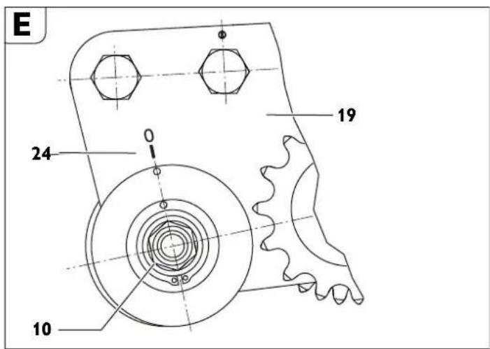
yauuuaaueaunnnaeunnnnneun
1
annnnnnae annne
aannnnnne nnnnnnnnnnnnnnnnnnnnnnnnnnnnnnnnnnnnnnnnnnnnnnnnnnnnnnnnnnnnnnnnnnnnnnnnnnnnnnnnnnnnnnnnnnnnnnnnnnnnnnn
yoyanj
y
yuaanrnnnnae
- nnnnnaanennnnnnnnnnnnnnnnnnnnnnnnnnnnnnnnnnnnnnnnnnnnnnnnnnnnnnnnnnnnnnnnnnnnnnnnnnnnnnnnnnnnnnnnnnnnnnnnnnnnnnnnnnnnnnnn
nnaaannnnnnne
- 1
nntnnnnnnnnnnnnnnnnnnnnnnnnnnnnnnnnnnnnnnnnnnnnnnnnnnnnnnnnnnnnnnnnnnnnnnnnnnnnnnnn
- muaaunnnaeauanrnnnne
n
nannnnnnnnnnnnnnnnnn
mnnnnaaannnnnne nnnnnnnnnnnnnnnnnnnnnnnnnnnnnnnnnnnnnnnnnnnnnnnnnnnnnnnnnnnnnnnnnnnnnnnnnnnnnnnnnnn
nannnnnnnnnnnnn
mnnnnaaennnnnne nnnnnnnnnnnnnnnnnnnnnnnnnnnnnnnnnnnnnnnnnnnnnnnnnnnnnnn
SAE 140 uunwun
1
nuiinianui
nannnnnnnnnnnnnnnnnnnnnnnnnnnnnnnnnnnnnnnnnnnnnnnnnnnnnnnnnnnnnnnnnnnnnnnnnnnnnnnnnnnnnnnnnnnnnnnnnnnnnnnnnnnnnnnnnnnn
()
and
mnnnne nnnnnnnnnnnnnnnnnnnnnnnnnnnnnnnnnnnnnnnnnnnnnnnnnnnnnnnnnnnnnnnnnnnnnnnnnnnnnnnnnnnnnnnnnnn
nalniou (nniuunau A)
FDA (Food and Drug Administration)
muaauiu
BIOCUT 3000
1L-321320390000
5L-32132040000
25°C
1L-32132042000
5L-32132043000
aunurwral RSG Ex (^**) uonnoanrnnnne (nnnaeFEIN
92601023023)
1
yina
Tnnnne nnnnne nnne ennnnne ennnnne ennnnne ennnnne ennnnne ennnnne ennnnne ennnnne ennnnne ennnnne ennnnne ennnnne ennnnne ennnnne ennnnne ennnnne ennnnne ennnnne ennnnne ennnnne ennnnne ennnnne ennnnne ennnnne ennnnne ennnnee
nssnnnnnnnnnnnnnn
muyuue CE mwnnnnunnnnnae EFTA (European Free Trade
Association) 135
FEIN
mnnnne nnnnnnnnnnnnnnnnnnnnnnnnnnnnnnnnnnnnnnnnnnnnnnnnnnnnnnnnnnnnnnnnnnnnnnnnnnnnnnnnnnnnnnnnnnnnnnnnnnnnnnnnnnnnnnnnnnn
ionnnnnn
C. & E. Fein GmbH,
Paaayy mllilng Mshnoln k Paaay P ar Kssnnl
gaiuee 1
- 3331 tuk k uolni uug gaoaeg cheon k o paahp miligag mshiln ke doanl Aor paoepke
- paiaay imiligimg mshoiin koo 0aaiy aor gaoiic oan k o gaoiie pihiv (20) ke jioe chokse, taikip aiauy imiligimg mshoiin rghoe ne k abad gaoiue oyel n dal tke fote me A
- 14 (19)
- gānàodú āyāntī kāo 30217216004) kāi gānáhyāyāntā rās āaḥpārśmī ājǎdú ājǎnālā Āhāyī ā ār ār ār ār ār ār ār ār ār ār ār ār ār ār ār ār ār ār ār ār ār ār ār ār ār ār ār ār ār ār ār ār ār ār
Gaiadug cheon kco khsnna (chir A d
- 5a#s#e Pah#e #o#n# #kuy 1) k## d##m#r#r #g#d# #e#n #o #h#rse #p#d#y p#r
- 196072345678901234567890123456789012345678901234567890123456789012345678901234567890123456789012345678901234567890
- katei dki pki kaiy a k de tayan gilin nki kihylati pae yhao n y adi pahay gao lal ne hie, let o i s sy a la to Puon: kakaa Jana ahaia ay kipar dai kajra jai jaih aaiiyk katei rse s pepele srehi 4 eikel nikkanal
1
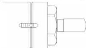
伊瓦尔克斯纳 乌拉 克 毕加特
1 7
1 电 费
1 !
K
Aahishikvichekpokot- rohiti aiaaiaan n aiaay
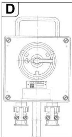
Jooan2 2 k e 100000000000000000000000000000000000000000000000000000000000000000000000000000000000000
R 1
A
Veyyagjayaray 2
Sahal
20
A 1
Chaluk kkrne k prkhya
doktikc mertuyuok pahayy knilngmas hshiln
mniitihk kareki dulk ke yhmane k hi tssr h
gianl dish k ririvaii rieh
O 1
- kijdi jijykr k o kijid jikrkt lioykr (28) ke dur r add k
- 伊哈乌伊·明尼维纳·马里亚尔·克·德布洛·卡瓦
- kaiyepag 11) dalal a kefi Aotk eok cckl kki sahayatla se chalotia u 4u 4u 4u 4u 4u 4u 4u 4u 4u 4u 4u 4u 4u 4u 4u 4u 4u 4u 4u 4u 4u 4u 4u 4u 4u 4u 4u 4u 4u 4u 4u 4u 4u 4u
- 1 - 1 - 1 - 1 - 1 - 1 - 1 - 1 - 1 - 1 - 1 - 1 - 1 - 1 - 1 - 1 - 1 - 1 - 1 - 1 - 1 - 1 - 1 - 1 - 1 - 1 - 1 - 1 - 1 - 1 - 1 - 1 -
suii jit kai 1 aadai t e aadai aadai aadai aadai aadai aadai aadai aadai
- 伊德尔克勒克纳夫卡 克亚达克勒克纳夫卡 肯斯曼格拉夫卡 3mm 远期免交 阿达克勒克纳夫卡 2mm 远期免交 乌塔克勒克纳夫卡 2mm 远期免交 乌塔克勒克纳夫卡 2mm 远期免交 乌塔克勒克纳夫卡 2mm 远期免交 乌塔克勒克纳夫卡 2mm 远期免交 乌塔克勒克纳夫卡 2mm 远期免交 乌塔克勒克纳夫卡 2mm 远期免交
- gaharai k a 2e 100000000000000000000000000000000000000000000000000000000000000000000000000000000000000000
- pahay mkiinig mshiln kai hivvch bnd k
- 2015年1月24日,卡塔尔伊亚(11)克萨夫·卡塔尔伊亚(11)
- 伊阿·伊·伊·伊·伊·伊·伊·伊·伊·伊·伊·伊·伊·伊·伊·伊·伊·伊·伊·伊·伊·伊·伊·伊·伊·伊·伊·伊·伊·伊·伊·伊·伊·伊·伊·伊·伊·伊·伊·伊·伊·伊·伊·伊·伊·伊·伊·伊·伊·伊·伊·
- 19028
- 朱瓦 莉克 毛加尼 公司
- Aarati kakti dke dolaran bideh uay paoayuok sakanee 3 Aoiar
Eepilkckshn aur durla kdo arar mJagm kkr sakane h iusalaiy
Sahar me pradlan kia gudpuk cnilan yko chinjhyamat AHnrataqul pur Aarri te k poa
durar k an alana jana dhayi (63305013002) (RSGEx1500A/B ( +) ) sahnye me dijlkiyur sahahayek Upakkrar)
Aor r vngarra-mukr sarnayy o se bunne huyo e k da nssrmaa l k - pāduy mīlīgīng Āmshīn kāo ābāvūrloáó āhōne sā āchāa
- Aotovrloaotn Hohota Hohota Hohota Hohota Hohota Hohota Hohota Hohota Hohota Hohota Hohota Hohota Hohota Hohota Hohota Hohota Hohota Hohota Hohota Hohota Hohota Hohota Hohota Hohota Hohota Hohota Hohota Hohota Hohota Hohota Hohota Hohota Hohota Hohota
- 1
- 1 (kafot a gay pahay kai duk) k o jirane s e bchanae ke lie
Motoi d'ovaiar aoe pao (s>10 mm) ke lil, oolig jok k mllg kcd charpo me kai janai cahie
S 1
Sahmukhayya 1 (2005) RSG Ex (**)
FDA (Food and Drug Administration)
Jgai (DAB)
:Joo
BIOCUT 3000
1L-321320390000
5L-32132040000
-25°C aol y 1
1L-321320420000
5L-321320430000
J5S JSAU jaiyuiyjaoi
-
yjdy jyjdyj
aaii jiai iai kaiy gaii gaii jai
J0g
45
(AaJgall)
jao 1000000000000000000000000000000000000000000000000000000000000
1
yjll jlllal lgljgljgljgljglj
:
(8)j
(5)ydy
-
(313 auiyuii jie, yaiy i jy
aJy
:
-
-
-
-
-
-
-
-
-
-
-
-
-
-
-
-
-
-
-
-
-
-
- 1.
-
-
-
-
-
-
-
-
-
-
-
-
-
-
-
-
-
-
-
-
-
y
H
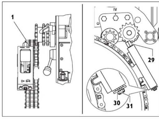
aaiiie
31,75
yj
| الإستعمال | الترجمة | الترجمة | ||
| ال三峡31,75 | ال三峡63,5 | [ال三峡] | [ال三峡] | |
| 1 | 1 710 250 | |||
| 0 | 4 1 870 300 | |||
| 1 | 6 1 1030 350 | |||
| 0 | 9 1 1190 400 | |||
| 1 | 1 2 1344 450 | |||
| 0 | 4 2 1500 500 | |||
| 1 | 6 2 1660 550 | |||
| 1 | 8 2 1809 600 | |||
| 1 | 1 3 1970 650 | |||
| 0 | 4 3 2130 700 | |||
| 1 | 6 3 2290 750 | |||
| 1 | 8 3 2440 800 | |||
| 0 | 1 4 2600 850 | |||
| 0 | 4 4 2760 900 | |||
| 0 | 6 4 2921 950 | |||
| 1 | 8 4 3079 1000 | |||
| 1 | 8 5 3397 1100 | |||
| 1 | 8 5 3714 1200 | |||
| 1 | 3 6 4032 1300 | |||
| 1 | 8 6 4330 1400 | |||
| 1 | 3 7 4640 1500 | |||
(635=1)30231034010
(-63,5=1)30231036010U
(p31,7=1)30231035010
.
(H)
-
(2)
()0 10
(30)j(29)
()50().
RSG Ex 18 A/B
1
| [р] | [р] | [р] | [р] | [р] | [р] |
| 5 | 2854 | 1427 | 587 | 250 | 1 |
| 5 | 3050 | 1525 | 576 | 300 | |
| 6 | 3264 | 1632 | 564 | 350 | |
| 6 | 3488 | 1744 | 553 | 400 | |
| 6 | 3564 | 1782 | 522 | 400 | 2 |
| 7 | 3796 | 1898 | 511 | 450 | |
| 7 | 4038 | 2019 | 501 | 500 | |
| 7 | 4288 | 2144 | 492 | 550 | |
| 8 | 4546 | 2273 | 483 | 600 | |
| 8 | 4604 | 2302 | 453 | 600 | 3 |
| 8 | 4866 | 2433 | 445 | 650 | |
| 9 | 5132 | 2566 | 437 | 700 | |
| 9 | 5404 | 2702 | 429 | 750 | |
| 10 | 5680 | 2840 | 422 | 800 | |
| 10 | 5724 | 2862 | 396 | 800 | 4 |
| 10 | 6002 | 3001 | 393 | 850 | |
| 10 | 6284 | 3142 | 390 | 900 | |
| 11 | 6568 | 3284 | 386 | 950 | |
| 11 | 6856 | 3428 | 383 | 1000 | |
| 11 | 6928 | 3464 | 390 | 1000 | 5 |
| 12 | 7214 | 3607 | 387 | 1050 | |
| 12 | 7502 | 3751 | 385 | 1100 | |
| 13 | 7792 | 3896 | 382 | 1150 | |
| 13 | 8124 | 4062 | 379 | 1200 | |
| 14 | 8676 | 4338 | 374 | 1300 | |
| 14 | 8710 | 4355 | 387 | 1300 | 6 |
| 15 | 9302 | 4651 | 382 | 1400 | |
| 16 | 9900 | 4950 | 378 | 1500 | |
| 17 | 10500 | 5250 | 373 | 1600 | |
| 18 | 11106 | 5553 | 369 | 1700 | |
| 19 | 11714 | 5857 | 366 | 1800 | |
| 20 | 12324 | 6162 | 362 | 1900 | |
| 21 | 12936 | 6468 | 359 | 2000 | |
| 22 | 13550 | 6775 | 356 | 2100 | |
| 23 | 14166 | 7083 | 353 | 2200 | |
| 24 | 14782 | 7391 | 350 | 2300 | |
| 25 | 15400 | 7700 | 348 | 2400 | |
| 26 | 16018 | 8009 | 346 | 2500 | |
| 27 | 16638 | 8319 | 343 | 2600 | |
| 28 | 17258 | 8629 | 341 | 2700 | |
| 29 | 17880 | 8940 | 339 | 2800 | |
| 30 | 18502 | 9251 | 337 | 2900 | |
| 31 | 19124 | 9562 | 335 | 3000 |
aai 31,75
$$ \therefore \tag {33} $$
$$ \varphi_ {1} \left(\frac {1}{2}, \frac {1}{2}\right) = \frac {1}{2} \cdot \frac {1}{2} \cdot \frac {1}{2} \cdot \frac {1}{2} \cdot \frac {1}{2} \cdot \frac {1}{2} \cdot \frac {1}{2} \cdot \frac {1}{2} $$
$$ \begin{array}{l} \therefore \text {i d} \left(\bigtriangleup \bigtriangleup \bigtriangleup \bigtriangleup \bigtriangleup \bigtriangleup \bigtriangleup \bigtriangleup \bigtriangleup \bigtriangleup \bigtriangleup \bigtriangleup \bigtriangleup \bigtriangleup \bigtriangleup \bigtriangleup \bigtriangleup \bigtriangleup \bigtriangleup \bigtriangleup \bigtriangleup \bigtriangleup \bigtriangleup \bigtriangleup \bigtriangleup \bigtriangleup _ {1}\right) = \ (3 3) \geqslant (1 - 1) \geqslant 2 ^ {2} - \ \therefore \text {a d} _ {\text {d}} (\mathbf {3 2}) \text {i n t i t a l} \quad - \ \end{array} $$
i.121
$$ \begin{array}{l} \left. \right.\left. \right.\left. \right.\left.\left.\left.\left.\left.\left.\left.\left.\left.\left.\left.\left.\left.\left.\left.\left.\left.\left.\left.\left.\left.\left.\left.\left.\left.\left.\left.\left.\left.\left.\left.\right.\right.\right.\right.\right.\right.\right.\right.\right.\right.\right.\right.\right.\right.\right.\right.\right.\right.\right.\right.\right.\right.\right.\right.\right.\right.\right.\right.\right.\right.\right. \ \therefore \text {s a l l} j i s t e w s l o w c l l \ \end{array} $$
#
m = 311 ;
$$ \begin{array}{l} \mathrm {d} S _ {1} \text {d} x \text {d} y \text {d} z \text {d} t \text {d} u \text {d} v \text {d} w \text {d} x \text {d} y \text {d} z \text {d} t \text {d} u \text {d} v \text {d} w \text {d} x \text {d} y \text {d} z \ \therefore a b c d e f g h i j k l m n o p q r s t \ \end{array} $$
$$ \begin{array}{l} - (2 8) \text {品} \ - \cdot \cdot \cdot \ \end{array} $$
$$ \begin{array}{l} \left. \right.\left. \right.\left. \right.\left. \right.\left. \right.\left. \right.\left. \right.\left. \right.\left. \right.\left. \right.\left. \right.\left. \right.\left. \right.\left. \right.\left. \right.\left.\left.\left.\left.\left.\left.\left.\left.\left.\left.\left.\left.\left.\left.\left.\left.\left.\left.\left. \text {i} _ {j} ^ {j} j ^ {j} j ^ {j} j ^ {j} j ^ {j} j ^ {j} j ^ {j} j ^ {j} j ^ {j} j ^ {j} j ^ {j} j ^ {j} j ^ {j} j ^ {j} j ^ {j} j ^ {j} j ^ {j} j ^ {j} j ^ {j} j ^ {j} j ^ {j} \right]\right]\right]\right]\right]\right]\right]\right]\right]\right]\right]\right]\right]\right]\right]\right]\right]\right]\right] \ \left. \int_ {0} ^ {1} f (x) d x = \int_ {0} ^ {1} f (x) d x \right| _ {0} ^ {1} = 0, \ - \cdot a \overline {{a}} \overline {{a}} \overline {{a}} \ \end{array} $$
$$ \begin{array}{l} i \dot {a} \dot {a} \dot {a} \dot {a} \dot {a} \dot {a} \dot {a} \dot {a} \dot {a} \dot {a} \dot {a} \dot {a} \dot {a} \dot {a} \dot {a} \dot {a} \dot {a} \dot {a} \dot {a} \dot {a} \dot {a}. \ \therefore j _ {i} = \sum_ {j = 1} ^ {n} j _ {i} = \sum_ {j = 1} ^ {n} j _ {i} = \sum_ {j = 1} ^ {n} j _ {i} \ (2 7) \text {i j} \text {a l l} \text {j} \text {a l l} \text {j} \text {a l l} \text {j} \text {a l l} \text {j} \text {a l l} \text {j} \text {a l l} \text {j} \text {a l l} \text {j} \text {a l l} \text {j} \text {a l l} \text {j} \text {(1)} \text {j} \text {(1)} \text {(1)} \text {(1)} \text {(1)} \text {(1)} \text {(1)} \text {(1)} \ \cdot \text {j a l l} j e \text {a l l} j e \text {a l l} j e \text {a l l} j e \text {a l l} j e \text {a l l} (2 7) \text {a l l} j e \text {a l l} j e \text {a l l} j e \text {a l l} j e \text {a l l} j e (2 8) \text {a l l} j e \ - \cdot \cdot \cdot \ \end{array} $$
$$ \begin{array}{l} i \dot {a} \dot {a} \dot {a} \dot {a} \dot {a} \dot {a} \dot {a} \dot {a} \dot {a} \dot {a} \dot {a} \dot {a} \dot {a} \dot {a} \dot {a} \dot {a} \dot {a} \dot {a} \dot {a} \dot {a} \dot {a}. \ \therefore j _ {i} = \sum_ {j = 1} ^ {n} j _ {i} = \sum_ {j = 1} ^ {n} j _ {i} = \sum_ {j = 1} ^ {n} j _ {i} \ (2 7) \text {i j} \text {a l l} \text {j} \text {a l l} \text {j} \text {a l l} \text {j} \text {a l l} \text {j} \text {a l l} \text {j} \text {a l l} \text {j} \text {a l l} \text {j} \text {a l l} \text {j} \text {a l l} \text {j} \text {(1)} \text {j} \text {(1)} \text {(1)} \text {(1)} \text {(1)} \text {(1)} \text {(1)} \text {(1)} \ \cdot \text {j a l l} j e \text {a l l} j e \text {a l l} j e \text {a l l} j e \text {a l l} j e \text {a l l} (2 7) \text {a l l} j e \text {a l l} j e \text {a l l} j e \text {a l l} j e \text {a l l} j e (2 8) \text {a l l} j e \ - \cdot \cdot \cdot \ \mathfrak {z} - \cdot (1 1) _ {\mathfrak {z}} \ - \cdot \cdot \cdot \ - \cdot (2 8) _ {4} \ - \cdot \bar {a} \bar {a} - 1 g _ {c} \ \end{array} $$
$$ \left. \text {i s i n t e r n a l} \right\rangle = \left. \right.\left. \right.\left. \right.\left. \right.\left. \right.\left. \right.\left. \right.\left. \right.\left. \right.\left. \right.\left. \right.\left. \right.\left. \right.\left. \right.\left. \right.\left. \right.\left. \right.\left. \right.\left. \right.\left. \right.\left. \right.\left. \right.\left.\left.\left.\left.\left.\left.\left.\left.\left.\left.\left.\left. 1 0 0 0 0 0 0 0 0 0 0 0 0 0 0 0 0 0 0 0 0 0 0 0 0 0 0 0 0 0 0 0 0 0 0 0 0 0 0 0 0 0 0 0 0 0 0 0 0 0 0 1 1 1 1 1 1 1 1 1 1 1 1 1 1 1 1 1 1 1 1 1 1 1 1 1 1 1 1 1 1 1 1 1 1 1 1 1 1 1 1 1 1 1 1 1 1 1 1 1 1 2 \right)\right)\right)\right)\right)\right)\right)\right)\right)\right)\right)\right) $$
$$ j _ {i} j _ {j} j _ {k} j _ {l} j _ {m} j _ {n} j _ {o} j _ {p} j _ {q} j _ {r} j _ {s} j _ {t} j _ {u} j _ {v} j _ {w} j _ {x} j _ {y} j _ {z} $$
$$ \text {s o l o} \left. \text {s o l o} \text {s o l o} \text {s o l o} \text {s o l o} \text {s o l o} \text {s o l o} \text {s o l o} \text {s o l o} \text {s o l o} \text {s o l o} \text {s o l o} \text {s o l o} \text {s o l o} \text {S O L O} ^ {(+)} \right. \text {R S G E x 1 5 0 0 A / B) (6 3 3 0 5 0 1 3 0 0 2)} $$
$$ \therefore \angle A B C = 1 8 0 ^ {\circ} $$
$$ \left. \right.\left. \right.\left. \right.\left. \right.\left. \right.\left. \right.\left. \right.\left. \right.\left. \right.\left. \right.\left. \right.\left.\left.\left.\left.\left.\left.\left.\left.\left.\left.\left.\left.\left.\left.\left.\left.\left.\left.\left.\left.\left.\left.\left. \text {的} \right]\right]\right]\right]\right]\right]\right]\right]\right]\right]\right]\right]\right]\right]\right]\right]\right]\right]\right]\right]\right]\right]\right] $$
$$ \left. \right.\left. \right.\left. \right.\left.\left.\left.\left.\left.\left.\left.\left.\left.\left.\left.\left.\left.\left.\left.\left.\left.\left.\left.\left.\left.\left.\left.\left.\left.\left.\left.\left.\left.\left.\left.\right.\right.\right.\right.\right.\right.\right.\right.\right.\right.\right.\right.\right.\right.\right.\right.\right.\right.\right.\right.\right.\right.\right.\right.\right.\right.\right.\right.\right.\right.\right. $$
$$ \therefore \frac {1}{2} a + b = 1 $$
$$ \therefore \quad j _ {i} = \frac {1}{2} \left[ \begin{array}{l l l l} 1 & 0 & 0 & 0 \ 0 & 1 & 0 & 0 \ 0 & 0 & 1 & 0 \end{array} \right] $$
$$ 3 0 0 \int_ {a} ^ {b} \frac {\sin x}{x} d x \int_ {a} ^ {b} \frac {\sin y}{y} d y \int_ {a} ^ {b} \frac {\sin z}{z} d z $$
$$ \therefore \text {的} = 6 0 0 $$
$$ \therefore \text {a l l} \quad \text {i t} \quad \text {i t} \quad \text {i t} \quad \text {i t} \quad \text {i t} \quad \text {i t} \quad \text {i t} \quad \text {i t} \quad \text {i t} \quad \text {i t} \quad \text {i t} \quad \text {i t} \quad \text {i t} \quad $$
$$ \cup \cup \cup \cup \cup \cup \cup \cup \cup \cup \cup \cup \cup \cup \cup \cup \cup \cup \cup \cup \cup \cup \cup \cup \cup \cup \cup \cup \cup \cup \cup \cup \cup \cup \cup \cup \cup $$
$$ \cdot \left((0 ^ {*}) \text {R S G E x}\right) \text {i} \text {i} \text {i} \text {i} \text {i} \text {i} \text {i} \text {i} \text {i} \text {i} \text {i} \text {i} \text {i} \text {i} \text {i} \text {i} \text {i} \text {i} \text {i} \text {i} \text {i l} $$
$$ ! \dot {s} \dot {s} \dot {s} \dot {s} \dot {s} \dot {s} \dot {s} $$
$$ (3 2) \quad \text {a n d} \quad \text {a n d} \quad \text {a n d} \quad \text {a n d} \quad \text {a n d} \quad \text {a n d} \quad \text {a n d} \quad \text {a n d} \quad \text {a n d} \quad \text {a n d} \quad \text {a n d} \quad \text {a n d} $$
Jaaalalalalalalalalalalalalalalalalalalalalalal
P 为 AQ = 2l
= - y1y2 - y_1
Jus Jus Jus Jus Jus Jus Jus Jus Jus Jus Jus
y
j 1
y
J 1
G
y
2 = 35
( xy^2 + 1) ( xz^2 + 1) = 0
i 1
jai 2006
J
B

J 134


J = 2


Jauydu Jd Jd d a 10000000000000000000000000000000000000000000000000000

J 15 J 15 J 15 J 15 J 15 J 15 J 15 J 15 J 15 J 15 J 15 J 15 J 15 J 15 J 15 J 15 J 15 J 15 J 15 J 15 J 15 J 15 J 15 J 15 J 15 J 15


1 1
50 j


y
(91201002004
S ACD = S COD + S_ CDE
25°C
(Aa)
(7)s(s(s(16)
jaiy (4) aaiy jay 100 (10) jaiy gao (9) ay
1
pS(8)wUuUuU
a 1
CUTYLL32039000 1
CU 51-3221-32040-0000
aall aal no jai jai jai ai yj jai jai jai k
13204(16)
132043000-5(6)
(20 1
a a a a a a a a a a a a a a a a a a a a
Jaa 1
(2)
aaii iiei iiee eae ee ()RSGExj jy 100000000000000000000000000000000000000000000000
()
AATEX
(d
2
i 3
4
e 2
5
5 6 7
8
10
11
12
13
14
15
y
(b)
14
15
c 16
17
18
19
jidai 20
18
(d 13
19
20
21
2
23
f 24
aaii 24
()25
Jann Jau 26
27
a.1234567890
j 29
yjdz1 30
31
jie jie jie jie 32
33
34
(4) 1,2,3,4 = 1,2,3,4
21
(h 28
j 29
yjdz1 30
31
jie jie jie jie 32
1
33
1
(d 1
aal
i
1
y
(1)
1
(1)
a
中
[1]
g
1
.
(h
i 1
aannnne aennnnne
45
a aaae aae e ae aee
a 1
.015 11 11111111111
.
Kopplingsaggregatkombination
30702041014
BnOK KOMyTauiHnx npnaIaIB
30702041014
En. Ta6no
30702041014
Lulitusseadme
30702041014
Komutaciniu prietaisy blokas
30702041014
Sadalesiekartu kombinacija
30702041014
RSG Ex 1500 A/B (^) RSG Ex 18 A/B (^)
接线图
接線圖
對今
回路
克藥安藥士
发动机接线图
發動機接線圖
皆同乐,
H
王一夕一回路图
Moototur kkanoeekshan
joll jolj
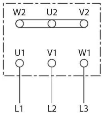
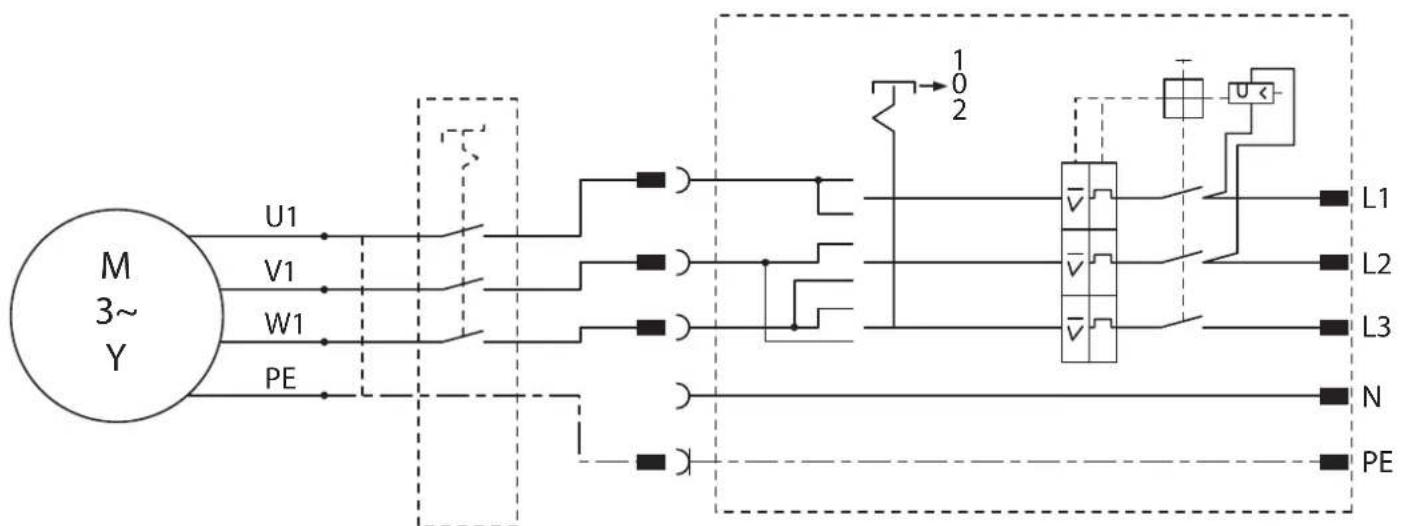
辅助开关
30722024017
輔助開關
30722024017
李杰杰刘
30722024017
a
30722024017
追加次个
30722024017
艾贝尼
30722024017
1
30722024017
开关设备装置
30702041014
開關設備裝置
30702041014
30702041014
y
30702041014
SイチギアSENPLI
30702041014
H
30702041014
Ssui 1
30702041014
C E
EN ISO 12100:2010
2011/65/EU, 2006/42/EG

U. Hegosell
i.V.S.Bohm i.V.Dr.M.Hergesell
Director of Quality Director of Product
Management Development
Schwablsch Gmund-Bargau, 15.10.2021
C. E. Fein GmbH
Hans-Feln-StraBe 81

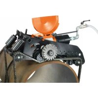
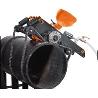
- Symbols, abbreviations and terms used.
- Technical Data.
- Intended Use of the Pipe Milling Machines.
- EC Directive 94/9EC ATEX (Atmosphères Explosibles)
- At a glance.
- For your safety.
- General safety rules.
- Specific safety rules for pipe milling machines.
- Electrically-operated pipe milling machines (design RSG Ex \\ ).
- Operation (see figure A).
- Transport.
- Before Starting Operation.
- Preliminary work on the pipe to be machined.
- Preliminary work on the pipe milling machine (see figure A).
- Clamping the pipe milling machine on the pipe.
- Mounting the chain links.
- Tensioning the chain links (see figure A).
- Mounting Application Tools.
- Danger of injury
- Starting Operation.
- Pipe milling machine:
- Pipe milling machine in partially explosion-proof design:
- Danger of explosion
- Operation.
- Danger of injury from chips/swarf being thrown about
- Danger of fire from chips/swarf being thrown about
- Starting procedure
- - Shut off the feed gearing via the feed switching lever (28).
- Return motion of the pipe milling machines (RSG Ex [ ] ).
- Possible damage!
- The pipe milling machine is not suitable for making cuts in return motion!
- Notes on cooling and lubrication.
- Observe the manufacturer's information/notes on the coolant being used
- Adjusting the running accuracy.
- Installing additional chain links.
- Clamping the pipe milling machine to a pipe.
- Example:
- Track guidance through guide chain
- Final work after each work assignment.
- Storing the pipe milling machine.
- Maintenance and Repairs.
- On maintenance and repairs.
- General information
- Maintenance of chain links
- Power supply cord
- Feed mechanism (see figure A)
- Disassembly:
- Assembly:
- Tightening device
- Lubricants and lubrication chart
- Lubricants for sliding surfaces
- Troubleshooting (Design RSG Ex (**)
- Warranty.
- Application Tools and Accessories.
- Circular saw blades
- Feather key
- Transport box
- Profile cutter
- Chain piece
- Spare pin
- Spare securing ring
- Spitting wedges made of steel
- Provided accessories
- Compressed-air cooling lubricant supply unit 9 12 01 002 00 4
- Spare parts.
- Declaration of conformity.
- Environmental protection, disposal.
- Cologne as correntes de eles.
- EuupaOaOynon Twv cpyaCioV eapuoyic.
- Kivouoc tpaupatopou
- Smoremidler til gldeflader
- Satsfres, HSS, for girity:
- Recipient de transport
- Freze
- HnpeKTHBa EC 94/9EC ATEX (Atmospheres Explosibles)
- KpaTHH 063Op.
- ДяВашев6e3oNaChOCTN.
- 06uhe yka3aHHn no TexHmke 6e3onacHOCTH.
- PNEyIeXeHHe NpoHTMe Bce yHa3aHHNo TeHXHe 630NaCHcTH, HNCTpyKHH, O3HaHObTeCb C HnIOCTpaHmH
- 1) Be3onachoctb pa6o4ero MecTa
- 2]3NeKtpoBe30nacHoctb
- 3) Be3onacHOCTb IIOdei
- Ippmehenne.
- PpHHnIeHCTBna (cm.phc.A).
- TpaHcnpTnpoBbKa.
- Hauana paobtbi.
- IodrotobHTeBhIbe padotbHa 06paatbIbAemOn Tpyoe.
- IpoIroTobKa TpyoOphipe3epHoMaunHbI (cM. pHC. A).
- 3aKpennHe TpyoOpeepHoi MaunnHi Ha Tpye.
- HanoMeHHe 3BeHbBbX qen
- HaTaeHHe 3BHeBeBbIX ueen (cm. pnc. A).
- Pmch BO3HHHOBeHHH HeCuaCTbIX CnyuaeB!
- YctahOBka pa6oOH HhCtpymENTOB.
- Onachoctb TpaBMPOBaHH
- Onachoctb TpaBMnpoBaHH
- BbOa B 3KcnnyatauHIO.
- Tpy6oΦpe3epna MaunHa:
- Tpyo0ppeepn Maunna BactuHb B3pb1B0e3onachm HcnoIHeHH:
- Onachoctb B3pbiba
- YnpabBHeHne.
- OnachoctbtpaBmPobAHnH3-3a pa3neTaOeIc cTpyKKn
- Onachoctb nonapa 13-3a pa3neTaIOUeIc sTpyKKn
- Onachoctb TpaBMPOBaHHA
- Ipoeypa npcka
- 06paThbXoTpyoΦpe3epHbIX MaHH (RSG Ex \一 ^ 一 \ )
- HaheceHne MATEpHnIbHoro yuepe6a!
- Tpyofopeepnmaunha He npnoHa nnpe3aHn Ha o6paTHOM xOy! yKa3aHH no OXnAHHN H CMA3Ke.
- Cnedyte daHHbIM/HHCTpyHcHm npOH3BODHTeI npHMehREMO OXlaHdaOuero cpeCTba
- HactpoHaToUHOCTXoJa.
- MOHTAM DonoJIHHTenbHbIX 3BeHbeB cENH.
- 3aKpenIeHne Tpy6oΦpe3epHoMaunHbI.
- PnHmep:
- 3aKnHouTheIbHbIe pa6oTbI nocJe KaHDoRo npHMeHeHHA.
- XpAHHe rpyo0pe3epHO MAHHbI.
- TexobcnyHnBaHne npemOH.
- TexobcnyKHBAHne H peMOHT.
- OnachoctbtpaBMPOBAAH
- 06uhe yha3aHH
- YXoJ 3a 3BHeBbeBbIMN ueiAMN
- Pmck BO3HMKHOBEHH Hecactbix CnyaeeB!
- UHyp nHTaHH
- Mexanh3m noaun Ha Bpe3aHne (cm. phc. A)
- DemyHTAM:
- Mortam:
- 3aHHMHe yCtpoHCTBO
- Cma30uHbIe CpeDCTBa H CXema Cma3KN
- YctpaHHeH HeHcnpabHObTei (KoHCTpyKmR RSG Ex (**)]
- Rapantna.
- Pabouhe HnctpymEnTbH nppHaJdJIeHHoCTH.
- HnpeKTHBa EC 94/9EG ATEX (Atmospheres Explosibles)
- Hopotn no orna.
- ДяВаообeзн.
- 3araJIbHI BkA3iBKN 3TexHKn 6e3neHN.
- TONEPEDEXEHHA
- 3epirahe Bci npabnna 3 TeXHH 6e3neK H I Bka3iBHN Ha MaHoyTHc.
- 1]Be3neKaHa po604omy Micui
- 2]EeIeHTpHua 6e3neKa
- 3)Be3neKaIIODeH
- 4) PpabHbHe NOOBMeHHra KOpHcTByBaHHeNEKtpPnHaamN
- 5) Cepsic
- Oc06nbi Bha3iBn 3 texhikn 6e3neKn dIa Tpyo0peepnX MaunH.
- EeIeKTHHITpy6oΦpe3epHI MaunHH (HOHCTpyuia RSG Ex (**)
- 3actocybaHHa.
- PpHHn p6oTH (Hb. Man. A).
- TpaHcnpTyBaHHa.
- Peped noathaom po60TH.
- Pi#roTOBui pOoTH Ha o6pOuHOBaHIN Tpyoi.
- PiIroTobKa TpyoΦpe3epHoMaunHH (Hb.MaJ.A).
- 3aKnipIneHH Tpyo0Φpe3epHoMaHNNHaTpy6i.
- HaKaNaDaHHaHKnOBHX NaHcHOrIb.
- HaTHryBaHHaNHOKBHX NaHcHOrIB (nB.MaI.A).
- He6e3neKa Heuaachoro BnnaHy!
- MohtakpobooHx hctpymehtib.
- He6e3neKa TpaBMH
- He6e3neKa TpaBMN
- BdraTe 3axnchI pykabni.
- Noatok po6oth.
- Tpyo0dpe3ephaMaunHa:
- Tpyo0oep3ephaMaunHa yactKOBo BHOyXo6e3neuH KOHcTpyu:
- He6e3neka Bn6yxy
- Ecnnyatauia.
- He6e3neHa TpaBMH
- Hebe3neKa TpaBMn Upe3 ctpyKky, 10 po3niTaTbcB
- He6e3neka nomemi uepe3 ctpyky, 0o po3niTaebcra
- IpoeUpa 3anycny
- 3aDhi xiT pyo0peepnMaunn (RSG Ex (**)
- ToHNOHeHHMaTepiJIbHNxCInHOcte!
- Tpy6ofope3epna MaunnHa He npH3haeHa nI p3aHH niA qac 3aHb0rO xOxy! Bka3IBKn 100 oxoOdoKeHH I 3MaueHH.
- ToHokHeHH MaTePiaIbHNx iHHocTei!
- Iotpmytech inopmaui/Bka3ibOK Bhp06HHKa OxIoNDHyBaNbHoro 3acOby, 00 3actocobyctc
- HaiaatbyaHHnTouHocTi xOy.
- MOHTAHI DOATKOBHX JAAHOK JAAHCORA.
- 3aKnipJIeHHa TpyoΦpe3epHoMaunnn.
- PnHna:
- Pyx 3a cmyroo 3a donomoro 0 Beyuoro nauuora
- Ybara-He63nHa HeuaChnx BnnaAdkib!
- 3aKJIOHoyi po60TH nicra KOHHoro 3actocybaHH.
- 36epirahn rpyo0pe3ephoMaunnn.
- Texhihe 06cnyrobyaHH i pemOHr.
- Texhihe 06cnyrobyaHHH i peMOHT.
- 3araJIbHI BkA3IBKN
- OOrn3aJahKOBHMJahUorAmH
- Hebe3neKa HeuacHOro BnnaHy!
- WHyp HMBJIeHHH
- Mexahi3m noaqui Ha Bpi3ybaHHA (HM. Man. A)
- Демогтам:
- MoHTaH:
- 3aTHCKHm npHcptpi
- 3mauzybailhi 3acobn i cxema 3mauybaHH
- 3mauybaJIbHI 3acO6H dIra NOBepxOHb KOB3aHHA
- 3axnCT HABKONHbOro cepedOBuA, yTnlaiai.
- H3noJI3BaHH cHMBOJH, CbKpaueHH H TePMHH.
- 3a Bawaata chryphoct.
- 06uynka3aHH3a 6e3onacHOCT.
- 5]Ioddbpkahe
- CneuHaHH yHa3aHH 3a 6e3oNaCHOCT npn pa6Ota C MaunHH 3a Φpe3oBaHe Ha Tpb6H.
- 3axpaHbAH C eIeKtpHcEBo Maunnn 3aΦpe3ObaHe Ha Tpb6n (Moden RSG Ex (**)
- Pa6ora.
- IopdbpHaTe pbKoXBaTKHe N NOBbpxHOCTHe Hm UcHn H63 OMacnBaHe.
- Onachoct or HapaHbahe
- BhJIOUbaHe.
- Maunha 3a 0pe3oBaHe Ha Tpb6n:
- Maunha 3aΦpe3oBaHe Ha Tpb6n B yacTH4Ho 6e30nachO 3a EHCnIO3HH3IbHHeHHe:
- OnachocOT EKCNIO3M
- Pa60ta c mawHHata.
- OnachOCT OT HapaHbAbe OT OXBpauu CTpyKKn
- OnachocT onokap OT OXTbbpauu CTpyKKn
- PpouecHaBKnIOUbaHe
- Onachoct ot HapaHbahe
- 06paTeH xoJ ha MaunHH 3a Phpe3ObaHe Ha Tpb6h (RSG Ex (**)
- Onachoct ot zeth!
- Maunnata 3a Ppe3oBaHe TpbH He MoMe da peme npn o6pAHHXoI
- Yka3aHaHa 3a OxlaHaDaHe H Cma3BaHe.
- Onachoct ot ets!
- Cn3BaIe yka3aHHa Ta HPOH3BOHTeHa No3BaHHpaOteH HhCTpyMeHT
- HactpoBaHe Ha ToUHOCTa Ha XOJa.
- Dobabhe Ha 3Bena Ha Bephrata.
- 3aKpenBaHe Ha MaWHHata 3a φpe3ObaHe Ha Tpb6H.
- BHHMaHHe, onachOcT or 3Jiononya!
- 3aHIOHTENHH DeHOCTH CNEBcAHO non3BaHe.
- CbxpaaHbAe Ha MaunHata 3a 0pe30BaHe Ha TpbH.
- NoabpHaHe npemOnr.
- 3a noDabpHaHe H pEmOHr.
- OnachOCT or HapaHnBaHe
- 06uynka3aHn
- Pe3epBHH qactn.
- Deknapaun 3a CbOTBETCTBHe.
- Ona3BaHe Ha OKoHata cpea, opakyBahe.
- Uldised ohutusjuhised.
- ATAHELEPANU
- Eeltoed enne toru tootlemist
- Vamzdziu frezavimo masin y paskirtis.
- Padeves icerice (attels A)
- Demontaza
- Montaža
- gredzenus!
- Spriegotajierice
- Smerviela un elosanas plans
- Kedes posms
- China RoHS Status Certificate
- 中国RoHS认证概况
- EC Directive 94/9EC ATEX (amwneanngnll)
- y
- nouuun
- y d aannnnaaannnn
- - 500
- nna (nnnuuA)
- nunnnnnae
- nunnnnnnnnnnnnnnnnnnnnnnnnnnnnnnnnnnnnnnnnnnnnnnnnnnnnnnnnnnnnnnnnnnnnnnnnnnnnnnnnnnnnnnnnnnnnnnnnnnnnnnnnnnnnnnnnnnnnnnn
- D
- n
- nunnnnnae nannnne nnnnnnne annnnnnnnnnnnnnn
- m
- mno:
- mua
- 1uuaaunueanrnnnnae
- aannnnnnaeennnne nnnnnnnnnnnnnnnnnnnnnnnnnnnnnnnnnnnnnnnnnnnnnnnnnnnnnnnnnnnnnnnnnnnnnnnnnnnnnnnnnnnnnnnnnnnnnnnnnnnnn
- nnaannnnnnaaennnna (RSG Ex ( )
- HUNHNNINNNNNNNNNNNNNNNNNNNNNNNNNNNNNNNNNNNNNNNNNNNNNNNNNNNNNNNNNNNNNNNNNNNNNNNNNNNNN
- JUHNNNNOYAAHUNNEAENNAANNNNNAHNN
- 1
- yoyanj
- - nnnnnaanennnnnnnnnnnnnnnnnnnnnnnnnnnnnnnnnnnnnnnnnnnnnnnnnnnnnnnnnnnnnnnnnnnnnnnnnnnnnnnnnnnnnnnnnnnnnnnnnnnnnnnnnnnnnnnn
- and
- nalniou (nniuunau A)
- yina
- nssnnnnnnnnnnnnnn
- Paaayy mllilng Mshnoln k Paaay P ar Kssnnl
- 伊瓦尔克斯纳 乌拉 克 毕加特
- Aahishikvichekpokot- rohiti aiaaiaan n aiaay
- Sahal
- Sahmukhayya 1 (2005) RSG Ex (**)
- H
- #
- P 为 AQ = 2l
- G
- J
- B
- J = 2
Brand : Fein
Model : Ex18a
Category : Milling machine