STM 1800 - Saw FESTOOL - Free user manual and instructions
Find the device manual for free STM 1800 FESTOOL in PDF.
User questions about STM 1800 FESTOOL
0 question about this device. Answer the ones you know or ask your own.
Ask a new question about this device
Download the instructions for your Saw in PDF format for free! Find your manual STM 1800 - FESTOOL and take your electronic device back in hand. On this page are published all the documents necessary for the use of your device. STM 1800 by FESTOOL.
USER MANUAL STM 1800 FESTOOL
natural_image
Mechanical support frame with multiple metal frames and wheels, no visible text or symbols
text_image
4x [A] 4x [B] 1 12x [C] 1-2 4x 1-3 4x 1-4 5x 1-5 4x 1-6 4x 1-7 2x 1-8 2x 1-9 1-1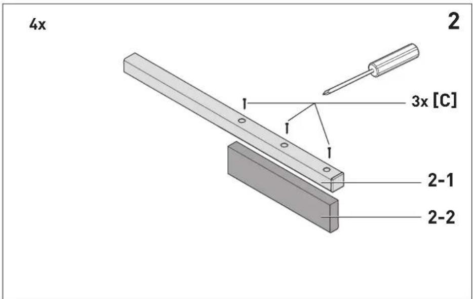
text_image
4x 2 3x [C] 2-1 2-2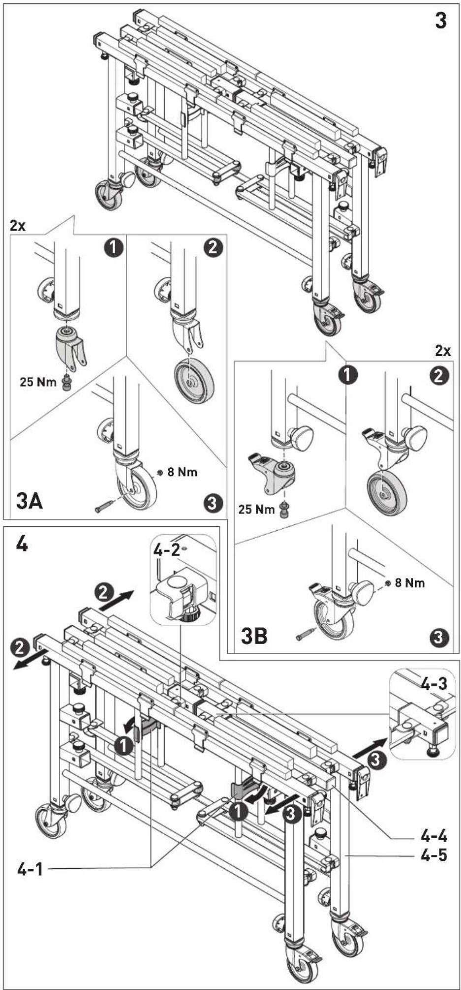
text_image
2x 25 Nm 8 Nm 3A 4 4-2° 3B 4-1 3 4-3 4-4 4-5 3 2x 25 Nm 8 Nm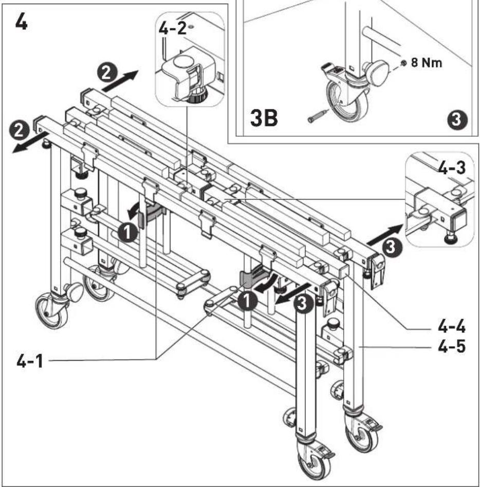
text_image
4 2 4-2 8 Nm 3B 3 4-3 1 3 1 3 4-1 4-4 4-5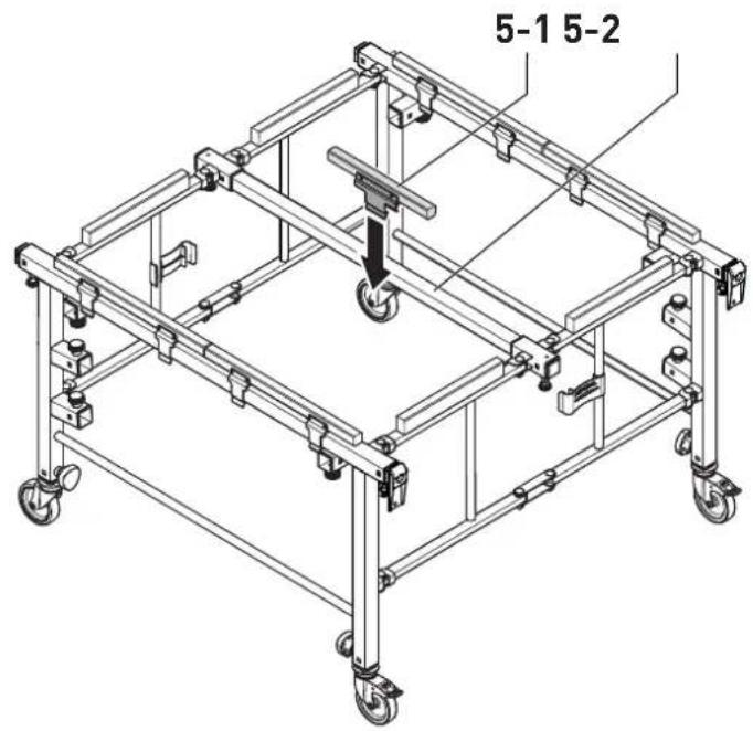
text_image
5-1 5-25
text_image
6-3 6-2 6-16
text_image
7-1 7-27
text_image
8-28-1 8-3 8A 8-58- 8-6 8B 8-7 8-88-9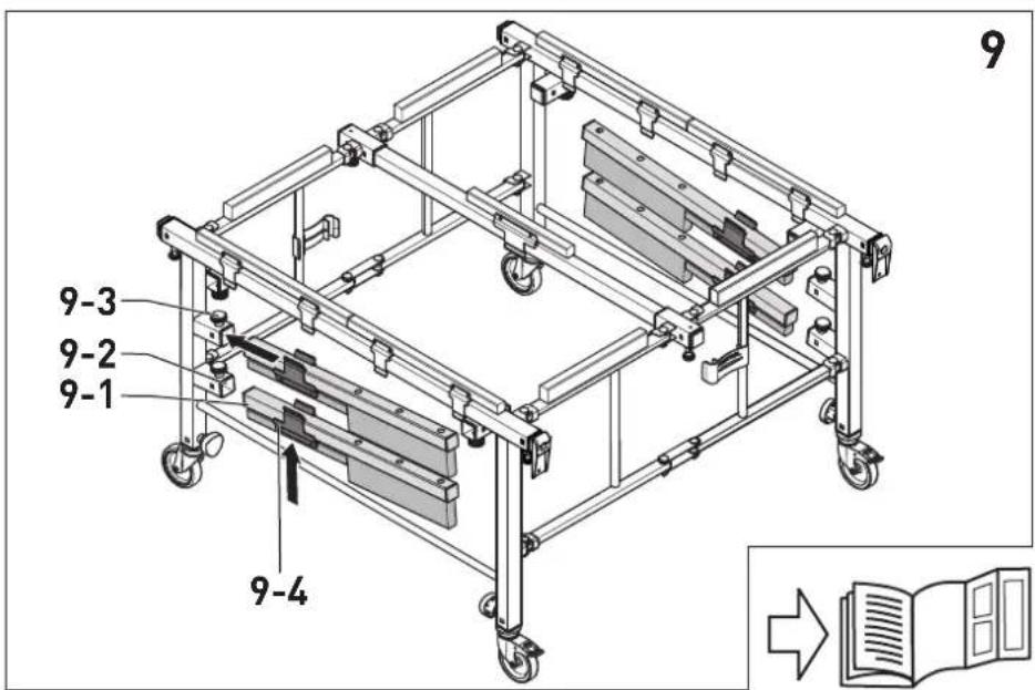
text_image
9 9-3 9-2 9-1 9-4Inhaltsverzeichnis
1 Symbole....6
2 Safety warnings....10
3 Intended use....10
4 Technical data.... 10
5 Items included....11
6 Assembly.... 11
7 Settings....11
8 Transportation....12
9 Working with the mobile saw table and work bench....12
10 Service and maintenance....13
11 Environment....13
1 Symbols

Warning of general danger

Read the operating instructions and safety instructions.

Do not climb on the unit

Max. load

Cutting depth max. 10 mm deeper than the thickness of the workpiece

Do not dispose of it with domestic waste.

Handling instruction

Tip or advice
2 Safety warnings

Warning! Read and observe all instructions and safety warnings. Failure to adhere to the warnings and instructions may cause serious injuries.
Keep all safety warnings and instructions in a safe place for future reference.
- Set the mobile saw table and work bench up correctly before carrying out any work.
Proper assembly is important in order to avoid the risk of the mobile saw table and work bench collapsing.
- Place the mobile saw table and work bench on a solid, even and horizontal surface. If the mobile saw table and work bench slides or wobbles, it may not be possible to control the power tool safely and reliably.
- Do not overload the mobile saw table and work bench and never use it as a ladder or trestle. Overloading or standing on the mobile saw table and work bench may shift the centre of gravity of the mobile saw table and work bench upwards and cause it to tip over.
- Pay attention to the maximum weight of the workpiece.
- Pay attention to the maximum workpiece dimensions.
- Replace damaged wooden supports if these can no longer guarantee secure support for the workpiece.
- Pay attention to the cutting depth when sawing. Select a cutting depth that is a maximum of 10 mm deeper than the thickness of the workpiece.


Wear suitable personal protective equipment: Protective gloves and safety shoes.
- Ensure that persons standing near the mobile saw table and work bench are at a safe distance from the work area.
3 Intended use
The mobile saw table and work bench is designed for safe, accurate sawing and routing in combination with Festool power tools.
Smaller workpieces can also be securely clamped to the mobile saw table and work bench by means of screw clamps*. The mobile saw table and work bench is consequently designed for many other tasks such as planing, grinding, milling, etc.
The tilting function facilitates the cutting and handling of large sheets.
* Not included in the scope of delivery.

The user is liable for improper or non-intended use.
4 Technical data
| Mobile saw table and work bench | STM 1800 |
| Table dimensions(width x length x height) when folded | 1150 x 250 x 700 mm |
| Min. contact surface 1100 x 1050 mm |
| Max. contact surface 1800 x 2100 mm |
| Mobile saw table and work bench | STM 1800 |
| Table height (adjustable) | 700–900 mm |
| Max. load 150 kg | |
| Max. workpiece dimensions(Tilting function) | 3100 x 2150 mm |
| Weight 34 kg |
5 Items included
[1-1] Folded mobile saw table and work bench
[1-2] Assembly accessories [A] 4x M6 screws with nuts [B] 4x M10 hexagon socket screws with washers [C] 12x T10 (wood 3 x 25 mm)
[1-3] 4x attachable tubes
[1-4] 4x wooden supports for fitting to the attachable tubes
[1-5] 5x pre-assembled wooden supports incl. clips
[1-6] 4x permanently fitted wooden supports
[1-7] 4x wheels
[1-8] 2x roller housings with brakes
[1-9] 2x roller housings without brakes
The illustrations specified are located at the beginning and end of the operating instructions.
6 Assembly
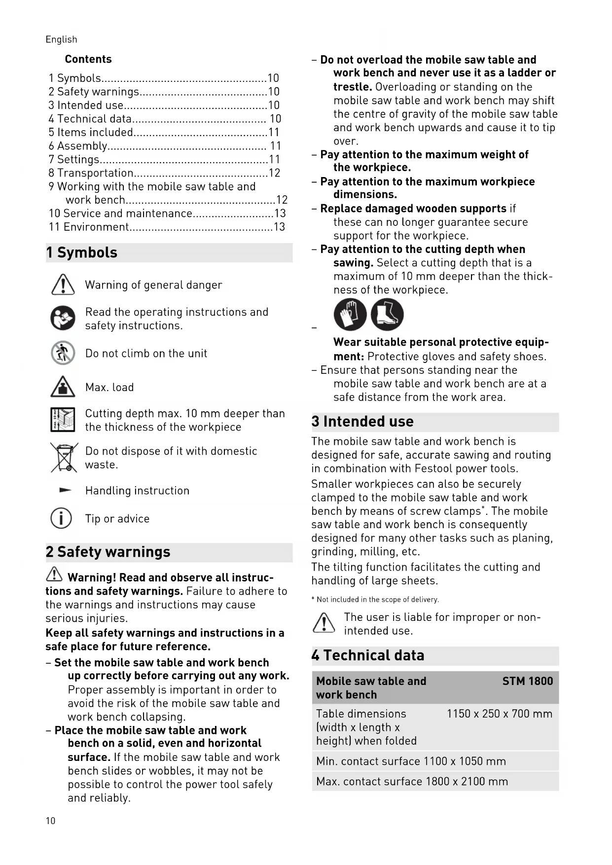
6.1 Fitting the wooden supports to the attachable tubes
▶ Screw the wooden support [2-2] to the attachable tube [2-1] with the screws [C].
▶ Fit the four wooden supports in this manner.
6.2 Fitting the wheels
Pay attention to the side of the premounted foot end caps. Fit the wheels without brake to the opposite side of the foot end caps (Fig. 3A). Fit the wheels with brake to the side of the foot end caps (Fig. 3B).
▶ ① Screw the roller housing with hexagon socket screw and washer [B] to the base tube.
▶ ② Insert the wheel into the roller housing.
3 Secure the wheel to the roller housing with a screw and nut [A].
▶ Fit the two wheels with brakes and the two wheels without brakes in this manner.
6.3 Unfolding the mobile saw table and work bench
▶ Open the transportation lock [4-1].
② Opposite the foot end caps: Pull apart the folding frame [4-5] until the locking bolt [4-2] locks into place.
▶ ③ Side of the foot end caps: Pull out the locking bolt [4-3] and pull apart the folding frame [4-5] by pushing the central rod [4-4] until the locking bolt [4-3] locks into place.
6.4 Fit the central wooden support incl. clips
- Clamp the wooden support premounted on clips [5-1] to the central tube of the folding frame [5-2].
The mobile saw table and work bench is ready for use.
7 Settings
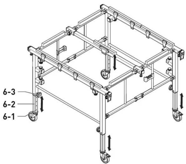
7.1 Adjusting the working height
The working height can be adjusted in increments of 50 mm between 700 mm and 900 mm.
▶ Loosen the locking knob [6-3], pull it out and keep it pulled out.
▶ Extend or insert the base tube [6-2] and lock it into one of the locking holes [6-1].
▶ Release the locking knob [6-3] and tighten it.
▶ Set the four base tubes to the same height in this manner.
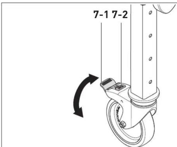
7.2 Adjusting the brakes
Locking the brakes
▶ Press down on the brake lever [7-1] until the brake fixture locks into place [7-2].
Releasing the brakes
▶ Press the brake lever [7-1] upwards until the brake fixture [7-2] is released.
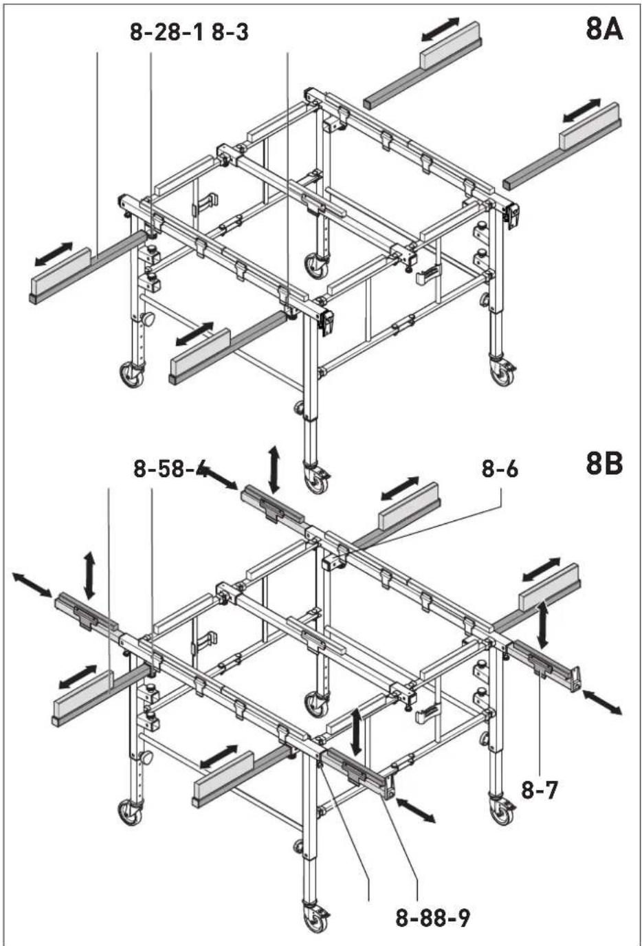
7.3 Extending the work surface
The work surface can be adjusted to the maximum dimensions of 1800 x 2100 mm.
Fitting the attachable tubes
▶ Release the rotary knob [8-2].
English
▶ Insert the attachable tube [8-1] into the holder opening [8-3] of the folding frame.
▶ Tighten the rotary knob [8-2].
▶ Fit the four attachable tubes to the folding frame in this manner.
Positioning the attachable tubes
▶ Release the rotary knob [8-5].
▶ Insert the attachable tube [8-4] into the required position, making sure that it has at least passed through the holder opening [8-6].
▶ Tighten the rotary knob [8-5].
- Position the four attachable tubes in this manner.
Positioning the extendable tubes
▶ Pull out the locking bolts [8-9] and keep them pulled out.
▶ Position the extendable tube [8-8].
▶ Release the locking bolts [8-9].
▶ Position the two extendable tubes with foot end caps and the two extendable tubes without foot end caps in this manner.
Fitting the wooden support incl. clips
▶ Clamp the wooden support premounted on clips [8-7] to the extendable tube [8-8].
▶ Fit the four wooden supports premounted on clips in this manner.
7.4 Reducing the work surface
The work surface can be adjusted to the minimum dimensions of 1100 x 1050 mm.
Detaching the attachable tubes
▶ Release the rotary knob [8-2].
▶ Pull the attachable tube [8-1] out of the holder opening [8-3] of the folding frame.
▶ Detach the four attachable tubes in this manner and store them (see section 8.2).
Detaching the wooden supports
▶ Detach the wooden support premounted on clips [8-7] from the extendable tube [8-8].
▶ Detach the four wooden supports premounted on clips in this manner and store them (see section 8.2).
Inserting the extendable tubes into the folding frame
▶ Pull out the locking bolts [8-9] and keep them pulled out.
- Insert the extendable tubes [8-8] into the folding frame.
▶ Release the locking bolts [8-9].
- Insert the four extendable tubes into the folding frame in this manner.
8 Transportation
8.1 Storing the wooden supports incl. clips
- Clip the wooden supports incl. clips [9-4] to the attachable tubes [9-1] for storage.
8.2 Storing the attachable tubes
▶ Release the rotary knob [9-3].
▶ Insert the attachable tube [9-1] into the storage holder opening [9-2].
▶ Tighten the rotary knob [9-3].
- Store the four attachable tubes incl. wooden supports in this manner.
8.3 Additional transport settings
▶ Reducing the work surface (see section 7.4).

WARNING
Risk of accidents occurring through the tilting saw table and work bench
▶ For transportation, slide in the base tubes all the way to the minimum working height (see section 7.1).
▶ Release the brakes (see section 7.2).
8.4 Folding up the mobile saw table and work bench
▶ Pull out the locking bolt [10-3] and push together the folding frame [10-4] until the locking bolt [10-3] locks into place.
▶ ② Pull out the opposite locking bolt [10-2] and push together the folding frame [10-4].
3 Close the transport lock [10-1].
The mobile saw table and work bench is ready for transportation.
i Observe all national safety regulations and ensure the load is secured when transporting it in a vehicle.
9 Working with the mobile saw table and work bench
The clip-on wooden supports can be moved as required, so that these are not damaged when working.

WARNING
Risk of accidents
▶ Clamp the workpieces with screw clamps *.
* Not included in the scope of delivery.
▶ For safety reasons, always lock the brakes when working.
9.1 Cutting depth

CAUTION
Damage to the wooden supports and the folding frame
▶ Set the cutting depth to a maximum of 10 mm deeper than the thickness of the workpiece (Fig. 11).
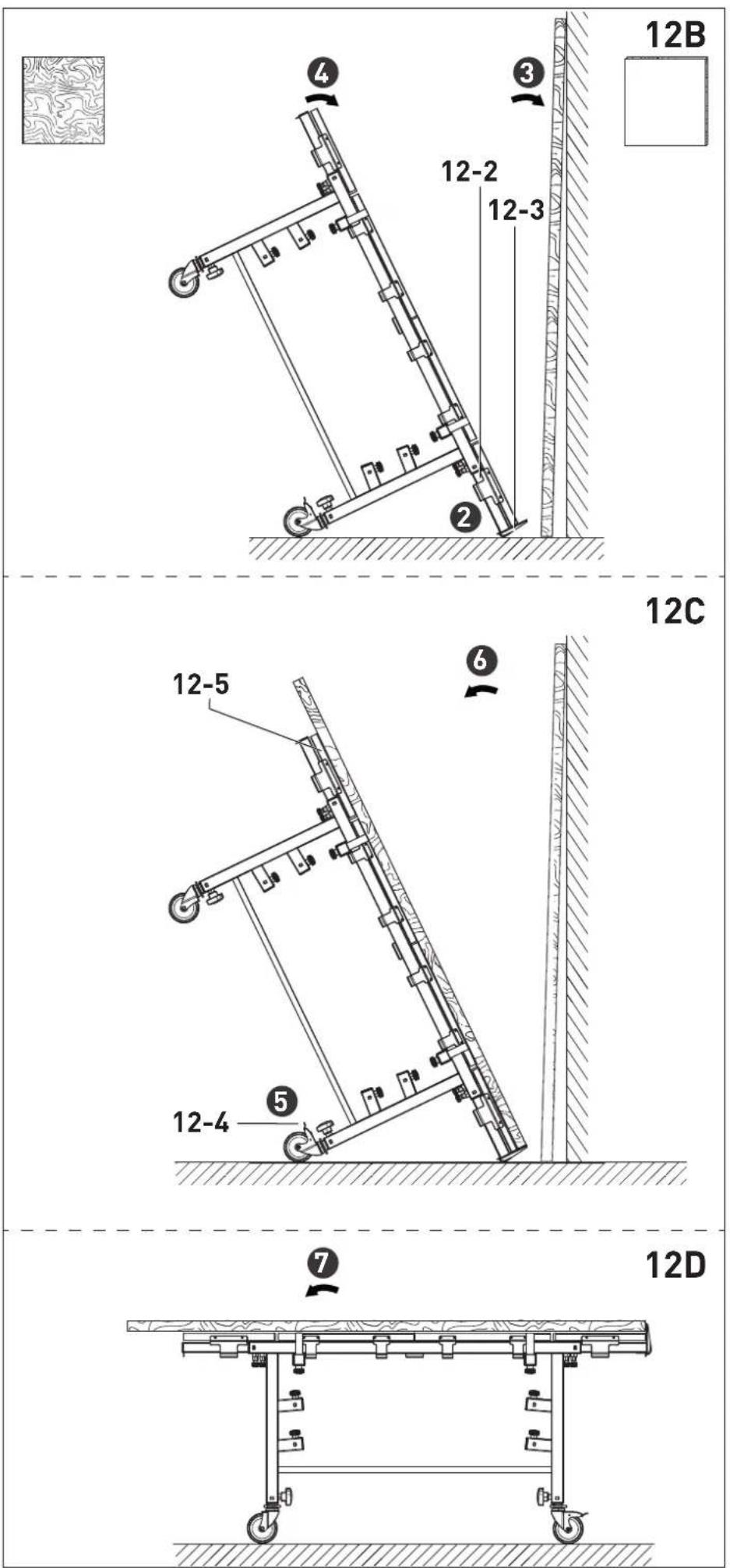
9.2 Supporting large sheets
Using the tilting function of the mobile saw table and work bench, a single person can support a sheet with dimensions ≤slant 3100 mm x 2150 mm.

WARNING
Risk of accidents
▶ Sheets > 3100 mm x 2150 mm must be placed and additionally supported on the mobile saw table and work bench by two people without the use of the tilting function.
▶ ① Turn both supporting feet [12-1] upwards.
▶ ② Pull the extendable tubes with supporting feet [12-2] out of the folding frame (see section 7.3).
3 Lean the large sheet against a wall.
▶ 4 Tilt the mobile saw table and work bench onto the supporting feet [12-3].
5 Lock the brakes [12-4] (see section 7.2).
▶ 6 Lift the plate onto the supporting feet [12-3] and lean it against the wooden supports [12-5] of the mobile saw table and work bench.
▶ ⑦ Tilt the mobile saw table and work bench back into the horizontal position.
10 Service and maintenance

Customer service and repairs must only be carried out by the manufacturer or service workshops. Find the nearest address at:
www.festool.co.uk/service

Always use original Festool spare parts. Order no. at: www.festool.co.uk/service
11 Environment

Do not dispose of the device in the household waste! Recycle devices, accessories and packaging. Observe applicable national regulations.
Information on REACH: www.festool.com/reach
Sommaire
[C] 12x T10 (ahşap 3 x 25 mm)
natural_image
Technical diagram showing intersecting mechanical components with no visible text or symbols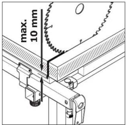
text_image
max. 10 mm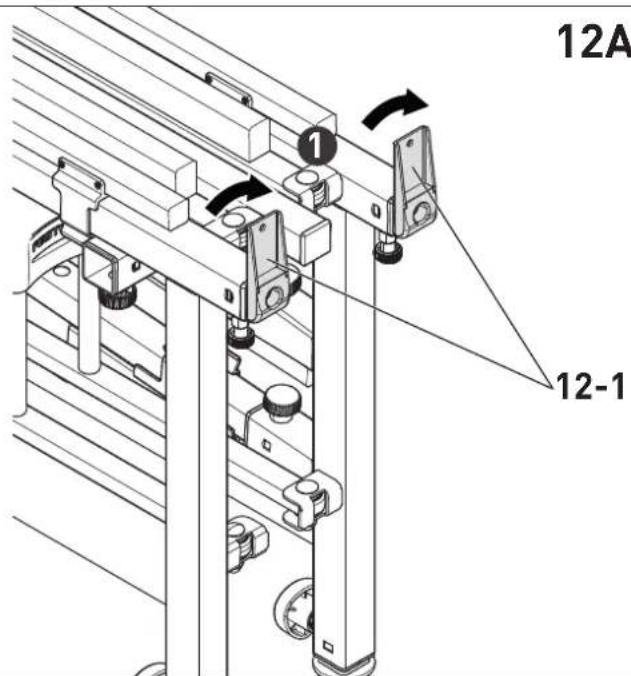
text_image
12A 1 12-1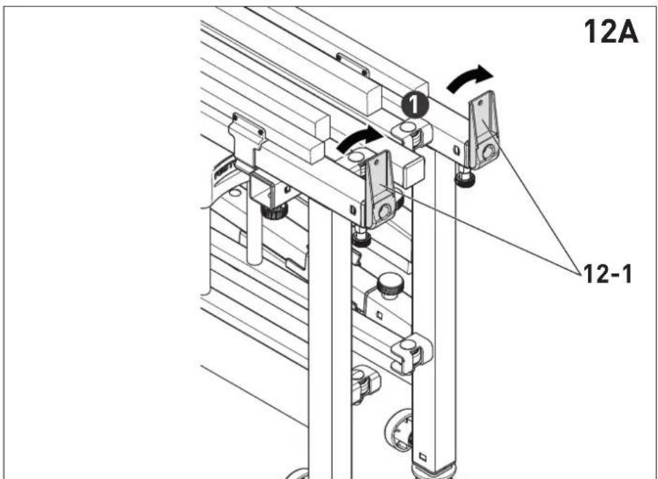
text_image
12A 12-1