PRECISIO CS 70 EG - Saw FESTOOL - Free user manual and instructions
Find the device manual for free PRECISIO CS 70 EG FESTOOL in PDF.

| Product type | Table and guided stationary saw |
| Brand | Festool |
| Model | PRECISIO CS 70 EG |
| Table dimensions (L x W) | 690 x 500 mm |
| Table height | 900 mm (extended), 375 mm (folded) |
| Weight (according to EPTA 01:2014) | 38.0 kg |
| Power supply | 220-240 V, 2100 W (EG model); 110 V, 1300 W (GB 110 V) |
| Max cutting height | 70 mm (at 90°), 48 mm (at 45°) |
| Blade tilt | -2° to 47° |
| Compatible saw blade | Diameter 225 mm, bore 30 mm, base blade thickness ≤ 2.2 mm, cutting width > 2.5 mm |
| No-load speed | 4200 min⁻¹ (EG model 220-240 V); 2000-4200 min⁻¹ (EBG model, adjustable) |
| Electrodynamic brake | Only on CS 70 EBG (stop in 3 seconds) |
| Electronic functions | Soft start, speed regulation, load limitation, thermal safety, restart protection |
| Dust extraction connection | Upper (Ø 27 mm) and lower (Ø 35 mm) |
| Safety devices | Protective guard, blade guide, red stop button, restart protection |
| Maintenance | Clean dust deposits, lubricate guide bars, replace worn carbon brushes |
| Spare parts and repairability | Use only original Festool parts; repair by the manufacturer or authorized workshops |
| Intended use | Sawing wood, plastics, laminated panels, aluminum (with specific blades) |
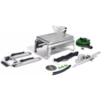
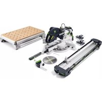
| Recommended accessories | Table extension, table extension, sliding table, extraction set |
| Sound level (LpA) | 84 dB(A); mandatory hearing protection |
Frequently Asked Questions - PRECISIO CS 70 EG FESTOOL
User questions about PRECISIO CS 70 EG FESTOOL
0 question about this device. Answer the ones you know or ask your own.
Ask a new question about this device
Download the instructions for your Saw in PDF format for free! Find your manual PRECISIO CS 70 EG - FESTOOL and take your electronic device back in hand. On this page are published all the documents necessary for the use of your device. PRECISIO CS 70 EG by FESTOOL.
USER MANUAL PRECISIO CS 70 EG FESTOOL
Head of Productdevelopment

Ralf Brandt
Head of Productconformity
6.3a Transportrollen
Table saw with sliding function CS 70 EG,CS 70 EBG
1 Symbols 22
2 Technical data 22
3 Parts of the machine 23
4 Intended use. 23
5 Safety instructions. 23
6 Set-up, operation 27
7 Settings on the machine 28
8 Scope of application 28
9 Working with the machine 31
10 Service and maintenance 33
11 Accessories, tools 34
12 Disposal 34
The specified illustrations appear at the beginning of the multilingual operating instructions.
1 Symbols

Warning of general danger

Risk of electric shock

Wear ear protection.

Wear a dust mask.

Wear protective gloves.

Wear safety goggles.

Read the manual/instructions

Safety class II

MMC Multi Material Control electronics

Dust extraction

Do not dispose of with household waste disposal

Handle area

Saw blade direction of rotation
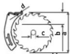
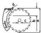
Saw blade measurement
a ... diameter
b ... max. cutting depth
c ... location hole
d ... riving knife thickness

Electro-dynamic rundown brake

Wood

Laminated wooden panels

Eternit fibre cement panel

Aluminium
2 Technical data
| Cutting height at 90°/45° 0-70 mm/ 0-48 mm | |
| Inclination | -2°-47° |
| Max. cutting length | 330 mm |
| Saw blade | 225 x 30 x 2.6 mm |
| Locating bore | 30 mm |
| Standard blade thickness | < 2.2 mm |
| Idling speed: | |
| CS 70 EBG, CS 70 EG (110 V) | |
| adjustable | 2000-4200 min-1 |
| CS 70 EG (220 - 240 V) | 4200 min-1 |
| Power consumption: | |
| CS 70 EBG, CS 70 EBG (GB 240 V), | |
| CS 70 EG (220 - 240 V) | 2100 W |
| CS 70 EBG CH | 2000 W |
| CS 70 EG (GB 110 V) | 1300 W |
| Table dimensions (L x W) | 690 x 500 mm |
| Table height, legs unfolded | 900 mm |
| Table height, legs folded away | 375 mm |
| Weight according to | |
| EPTA-Procedure 01:2014 | 38.0 kg |
Saw blades to be used
You can find the recommended saw blades for the various materials in the catalogue or at www. festool.com/service.
3 Parts of the machine
The specified illustrations appear at the beginning of this operating manual.
[1-1] Foldaway legs
[1-2] On/off switch
[1-3] Extra feet
[1-4] Clamping screws
[1-5] Fence position marking
[1-6] Preset profile setting rail position marking
[1-7] Table insert
[1-8] Guard
[1-9] Notch lever
[1-10] Cutting height setting
[1-11] Knobs for adjusting the foldaway legs
[1-12] End cap
[1-13] Handle area
4 Intended use
The PRECISIO is designed as a transportable power tool for sawing wood, plastics, panel materials made of wood and similar materials.
When fitted with the special saw blades for aluminium that are offered by Festool, these machines can also be used for sawing aluminium. Materials containing asbestos must not be processed.

The user is liable for damage and accrued by improper and non-intended use.
5 Safety instructions
5.1 General safety instructions

WARNING! Read all safety warn
ings, instructions, illustrations and specifications provided with this power tool. Failure to follow all instructions listed below may result in electric shock, fire and/or serious injury.
Keep all safety information and instructions for future reference.
The term "power tool" used in the safety instructions refers to mains-powered power tools (with power cable) or battery-powered power tools (without power cable).
5.2 Safety instructions for table saws
Guarding related warnings
a. Keep guards in place. Guards must be in working order and be properly mounted. A guard that is loose, damaged, or is not functioning correctly must be repaired or replaced.
b. Always use saw blade guard and riving knife for every through-cutting operation. For through-cutting operations where the saw blade cuts completely through the thickness of the workpiece, the guard and other safety devices help reduce the risk of injury.
c. Immediately reattach the guarding system after completing an operation (such as rabbeting, dodoing or resawing cuts) which requires removal of the guard and/or riving knife. The guard, riving knife, and anti-kickback device help to reduce the risk of injury.
d. Make sure the saw blade is not contacting the guard, riving knife or the workpiece before the switch is turned on. Inadvertent contact of these items with the saw blade could cause a hazardous condition.
e. Adjust the riving knife as described in this instruction manual. Incorrect spacing, positioning and alignment can make the riving knife ineffective in reducing the likelihood of kickback.
f. For the riving knife to work, it must be engaged in the workpiece. The riving knife is ineffective when cutting workpieces that are too short to be engaged with the riving knife. Under these conditions a kickback cannot be prevented by the riving knife.
g. Use the appropriate saw blade for the riving knife. For the riving knife to function properly, the saw blade diameter must match the appropriate riving knife and the body of the saw blade must be thinner than the thickness of the riving knife and the cutting width of the saw blade must be wider than the thickness of the riving knife.
Cutting procedures warnings

DANGER: Never place your fingers or hands in the vicinity or in line with the saw blade. A moment of inattention or a slip could direct your hand towards the lade and result in serious personal inju
b. Feed the workpiece into the saw blade or cutter only against the direction of rotation.
Feeding the workpiece in the same direction that the saw blade is rotating above the table may result in the workpiece, and your hand, being pulled into the saw blade.
c. Never use the mitre gauge to feed the workpiece when ripping and do not use the rip fence as a length stop when cross cutting with the mitre gauge. Guiding the workpiece with the rip fence and the mitre gauge at the same time increases the likelihood of saw blade binding and kickback.
d. When ripping, always apply the workpiece feeding force between the fence and the saw blade. Use a push stick when the distance between the fence and the saw blade is less than 150mm and use a push block when this distance is less than 50mm . "Work helping" devices will keep your hand at a safe distance from the saw blade.
e. Use only the push stick provided by the manufacturer or constructed in accordance with the instructions. This push stick provides sufficient distance of the hand from the saw blade.
f. Never use a damaged or cut push stick. A damaged push stick may break causing your hand to slip into the saw blade.
g. Do not perform any operation "freehand". Always use either the rip fence or the mitre gauge to position and guide the workpiece. "Freehand" means using your hands to support or guide the workpiece, in lieu of a rip fence or mitre gauge. Freehand sawing leads to misalignment, binding and kickback.
h. Never reach around or over a rotating saw blade. Reaching for a workpiece may lead to accidental contact with the moving saw blade.
i. Provide auxiliary workpiece support to the rear and/or sides of the saw table for long and/or wide workpieces to keep them level. A long and/or wide workpiece has a tendency to pivot on the table's edge, causing loss of control, saw blade binding and kickback.
j. Feed workpiece at an even pace. Do not bend or twist the workpiece. If jamming occurs, turn the tool off immediately, unplug the tool then clear the jam. Jamming the saw blade by the workpiece can cause kickback or stall the motor.
k. Do not remove pieces of cut-off material while the saw is running. The material may become trapped between the fence or inside the saw blade guard and the saw blade pulling your fingers into the saw blade. Turn the saw off and wait until the saw blade stops before removing material.
- Use an auxiliary fence in contact with the table top when ripping workpieces less than 2mm thick. A thin workpiece may wedge under the rip fence and create a kickback.
Kickback causes and related warnings
Kickback is a sudden reaction of the workpiece due to a pinched, jammed saw blade or misaligned line of cut in the workpiece with respect to the saw blade or when a part of the workpiece binds between the saw blade and the rip fence or other fixed object.
Most frequently during kickback, the workpiece is lifted from the table by the rear portion of the saw blade and is propelled towards the operator.
Kickback is the result of saw misuse and/or incorrect operating procedures or conditions and can be avoided by taking proper precautions as given below.
a. Never stand directly in line with the saw blade. Always position your body on the same side of the saw blade as the fence. Kickback may propel the workpiece at high velocity towards anyone standing in front and in line with the saw blade.
b. Never reach over or in back of the saw blade to pull or to support the workpiece. Accidental contact with the saw blade may occur or kickback may drag your fingers into the saw blade
c. Never hold and press the workpiece that is being cut off against the rotating saw blade. Pressing the workpiece being cut off against the saw blade will create a binding condition and kickback.
d. Align the fence to be parallel with the saw blade. A misaligned fence will pinch the workpiece against the saw blade and create kickback.
e. Use a featherboard to guide the workpiece against the table and fence when making nonthrough cuts such as rabbeting, dadoing or resawing cuts. A featherboard helps to control the workpiece in the event of a kickback.
f. Use extra caution when making a cut into blind areas of assembled workpieces. The protruding saw blade may cut objects that can cause kickback.
g. Support large panels to minimise the risk of saw blade pinching and kickback. Large panels tend to sag under their own weight.
Support(s) must be placed under all portions of the panel overhanging the table top.
h. Use extra caution when cutting a workpiece that is twisted, knotted, warped or does not have a straight edge to guide it with a mitre gauge or along the fence. A warped, knotted, or twisted workpiece is unstable and causes misalignment of the kerf with the saw blade, binding and kickback.
i. Never cut more than one workpiece, stacked vertically or horizontally. The saw blade could pick up one or more pieces and cause kickback.
j. When restarting the saw with the saw blade in the workpiece, centre the saw blade in the kerf so that the saw teeth are not engaged in the material. If the saw blade binds, it may lift up the workpiece and cause kickback when the saw is restarted.
k. Keep saw blades clean, sharp, and with sufficient set. Never use warped saw blades or saw blades with cracked or broken teeth. Sharp and properly set saw blades minimise binding, stalling and kickback.
Table saw operating procedure warnings
a. Turn off the table saw and disconnect the power cord when removing the table insert, changing the saw blade or making adjustments to the riving knife or saw blade guard, and when the machine is left unattended. Precautionary measures will avoid accidents.
b. Never leave the table saw running unattended. Turn it off and don't leave the tool until it comes to a complete stop. An unattended running saw is an uncontrolled hazard.
c. Locate the table saw in a well-lit and level area where you can maintain good footing and balance. It should be installed in an area that provides enough room to easily handle the size of your workpiece. Cramped, dark areas, and uneven slippery floors invite accidents.
d. Frequently clean and remove sawdust from under the saw table and/or the dust collection device. Accumulated sawdust is combustible and may self-ignite.
e. The table saw must be secured. A table saw that is not properly secured may move or tip over.
f. Remove tools, wood scraps, etc. from the table before the table saw is turned on. Dis- traction or a potential jam can be dangerous.
g. Always use saw blades with correct size and shape (diamond versus round) of harbour holes. Saw blades that do not match the mounting hardware of the saw will run off-centre, causing loss of control.
h. Never use damaged or incorrect saw blade mounting means such as flanges, saw blade washers, bolts or nuts. These mounting means were specially designed for your saw, for safe operation and optimum performance.
i. Never stand on the table saw, do not use it as a stepping stool. Serious injury could occur if the tool is tipped or if the cutting tool is accidentally contacted.
j. Make sure that the saw blade is installed to rotate in the proper direction. Do not use grinding wheels, wire brushes, or abrasive wheels on a table saw. Improper saw blade installation or use of accessories not recommended may cause serious injury.
5.3 Machine-specific safety instructions
- Only use tools that meet standard EN 847-1.
- This includes the saw blades recommended by the manufacturer in this operating manual.
- Only use saw blades with the following dimensions: Saw blade diameter 225mm ; cutting width 2.5mm , location hole 30mm ; standard blade thickness < 2.2mm ; suitable for speeds of up to 4200min^-1 .
- Saw blades made of high-alloy high-speed steel (HSS steel) must not be used.
- The cutting width of the saw blade must be greater and the standard blade thickness must be smaller than the thickness of the riving knife of 2.2mm .
- The tool must be suitable for the material you are working on.
- Deformed or cracked saw blades and saw blades with blunt or faulty cutting edges must not be used.
- When assembling the tools, ensure that the clamping takes place on the tool hub or the clamping surface of the tool, and that the cutting edges do not come into contact with one another or the fixed clamps.
-
Retaining screws and nuts must be tightened using suitable keys, etc. and with the torque specified by the manufacturer.
-
Clean any contamination, grease, oil and water off the clamping surfaces.
- Clamping screws must be tightened according to the manufacturer's instructions.
- Do not lengthen the key or tighten by hitting with a hammer.
- The tools must be stored and transported in a suitable container.
- Only use the machine if all safety devices are in their correct positions, the machine is in good condition and has been well maintained.
- Replace worn or damaged (e.g. by saw blade cuts) plates without delay.
- Operating personnel must have received adequate training in the use, set-up and operation of the machine.
- Faults on the machine, including the separating guards or the tool, must be reported to maintenance staff immediately upon discovery. The machine must not be used until the fault has been eliminated.


of hearing loss, safety goggles, a dust mask to prevent inhalation of harmful dust, protective
gloves when working with raw materials and when handling tools.
- To minimise noise, the tool must be sharpened and all noise-reducing elements (covers, etc.) must be properly adjusted.
- When cutting wood, connect the machine to a dust extractor corresponding to EN 60335-2-69, dust class M.
- To minimise the release of dust, the machine should be connected to a suitable dust extractor. All dust extraction elements (dust extraction attachments, etc.) must be properly adjusted.
- Never process material that contains asbestos.
- Make sure that you have enough light in the room or work place.
-
When sawing, adopt the correct working position:
-
At the front on the side of the operator;
- Head-on to the saw;
-
Beside the line of cut.
-
Use the accompanying push stick to guide the workpiece accurately past the saw blade.
- Always use the supplied riving knife and the guard. Ensure that they are set correctly as described in the operating instructions. If the riving knife is set incorrectly and components
that are required for safety reasons (such as the guards) are removed, this may result in serious injuries.
- Use a suitable device to support long workpieces and ensure that they are horizontal.
- Pull the plug from the mains power socket before changing tools and rectifying faults such as removing trapped splinters.
- Do not remove offcuts or other workpiece parts from the cutting area while the machine is still running or before the saw blade stops moving.
- If the saw blade jams, switch the machine off immediately and disconnect the mains plug. Do not remove the jammed workpiece until you have done this.
- Cutting rebates or grooves is only permitted when a suitable protective device has been fitted, e.g. a protective tunnel over the saw table.
- Reinstall the safety equipment immediately after work that requires the guard to be removed, see section 6.2b.
- Do not use circular saws for cutting slots (grooves in workpiece).
- Before transporting the machine, make sure that the top guard covers the top section of the saw blade.
- Do not use the top guard as a handle for transportation.
- When not in use, store the push stick in the accessory holder provided on the machine.
- Use only original Festool accessories and aids.
- Use of your own aids e.g. push stick, rulers, etc. is not permitted.
- Before commencing work, check that the guard and splinter guard can move freely and are resting on the table.
- To prevent the saw blade from overheating or the plastic from melting, set the correct speed for the cutting material and do not use excess pressure when cutting.
- When cutting metal, switch on the saw using a residual current circuit breaker.
- Check the plug and the cable regularly and should either become damaged, have them replaced by an authorised after-sales service workshop.
- Only for AS/NZS: The tool shall always be supplied via residual current device with a rated residual current of 30mA or less.
5.4 Emission levels
Typically, the noise levels that are determined in accordance with EN 62841 (see EC declaration of conformity) are as follows:
| Sound pressure level | LpA= 84 dB(A) |
| Sound power level | LwA= 98 dB(A) |
| Measuring uncertainty allowance | K = 3 dB |


CAUTION
The noise produced during work may damage your hearing.
Wear ear protection!
- The specified noise emission levels have been measured in accordance with the standard testing method and can be used to compare tools.
- The specified noise emissions can also be used for making preliminary estimates regarding noise load.


CAUTION
The noise emissions during actual use of the power tool can differ from the declared values depending on the ways in which the tool is used especially what kind of workpiece is processed.
- Identify safety measures to protect the operator that are based on an estimation of exposure in the actual conditions of use (taking account of all parts of the operating cycle such as the times when the tool is switched off and when it is running idle in addition to the trigger time).
5.5 Other risks
In spite of compliance with all relevant design regulations, dangers may still present themselves when the machine is operated, e.g.:
-Workpiece parts being thrown off,
- Parts of damaged tools being thrown off,
- Noise emissions,
- Wood dust emissions.
6 Set-up, operation


WARNING
Risk of accident if the machine is operated using the incorrect voltage or frequency.
The line voltage and frequency of the power supply must match those specified on the machine's rating plate.
- Only Festool machines with a rated voltage of 120 Volt may be used in North America.
Before use always inspect the flexible lead and the plug. Have the defects repaired by a specialist repair shop.
Outside the premise use only approved extension leads and cable connections.
6.1 Setting up the machine
Ensure that the floor around the machine is level, in good condition and free of loose objects (e.g. chips and offcuts).
The machine can be set up with or without the legs unfolded.
To unfold the legs: Loosen the four rotary knobs [1-11] all the way.
Unfold the legs [1-1] and tighten the rotary knobs [1-11] again.
If the machine wobbles, the length of one leg can be adjusted by turning the end cap [1-12] until the machine stands securely.
6.2 Prior to initial operation
6.2a Fitting the knob
Screw the supplied rotary knob [2-6] anticlockwise into the guide rod.
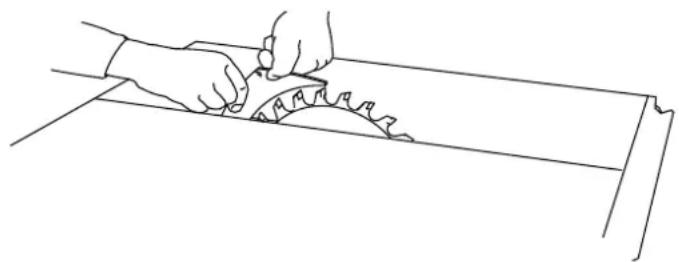
6.2b Installing the guard (fig. 12)
Remove the yellow safety sticker [12-4].
- Set the saw to maximum cutting depth and then omit to 0^ .
Pull the riving knife [12-1] into the upper position.
1 Take hold of the guard [12-3] and completely unscrew the screw [12-2].
Place the guard [12-3] on the riving knife [12-1]. In doing this, guide the lengthwise pin that is located in the guard [12-3] into the groove [12-6] on the riving knife [12-1] and push the screw [12-2] into the hole [12-5] in the riving knife [12-1] and tighten it.
3 Tighten the screw [12-2].
6.2c Installing the preset profile setting rail
Push the handle of the preset profile setting rail into the zero position (fig. 15). Tighten the screw [3-6] (fig. 3) and attach it to the table.
6.3 Transportation

When transporting the power tool, hold it by the handle areas on the sides [1-13]. Never take hold of or transport the power tool by the protective cover.
- Click the saw unit into place in the zero position.
- Remove all attachments from your saw and wind the cable around the cable holder.
Fold up the legs if necessary.
6.3a Transport rollers
The machine is equipped with transport rollers for moving it over short distances.
Take hold of the power tool by the handle area [1-13] and pull it to the desired place.
6.4 On/off switch
We recommend using a 16A fuse because of the high power of the motor.
To switch the machine on: Press the green "On" switch [1-2]. The red button is the "Off" switch.
7 Settings on the machine

WARNING
Risk of accident, electric shock
Always disconnect the mains plug from the socket before performing any work on the machine.
7.1 Electronics
The machine has full-wave electronics with the following properties:
Smooth start-up
The electronically controlled smooth start-up function ensures that the machine starts up smoothly.
Speed control
The speed (CS 70 EBG, CS 70 EG (110 V) only) can be set anywhere between 2000 and 4200min^-1 using the adjusting wheel [2-1]. This enables you to optimise the cutting speed to suit the respective material.
| # | \( {\mathrm{n}}_{0}\left\lbrack {\mathrm{{min}}}^{-1}\right\rbrack \) | # | \( {\mathrm{n}}_{0}\left\lbrack {\mathrm{{min}}}^{-1}\right\rbrack \) |
| 1 | ~ 2000 | 4 | ~ 3300 |
| 2 | ~ 2400 | 5 | ~ 3800 |
| 3 | ~ 2800 | 6 | ~ 4200 |
The preselected motor speed is kept constant through electronic control. This ensures a uniform cutting speed even when under load.
Overload safety device
The power supply is restricted if the machine is overloaded to extremes. The power supply is disconnected completely if the motor jams for some time. You will need to remove the load and/or switch off the machine before you can use it again.
Temperature cut-out
The power supply is restricted and the speed reduced if the motor exceeds a certain temperature. The machine continues operating at reduced power to allow the ventilator to cool the motor quickly. The machine starts up again automatically once the motor has cooled sufficiently.
Brake (CS 70 EBG only)
The saw blade is stopped electronically within 3 seconds of switching off the machine.
Restart protection
The built-in undervoltage release prevents the machine from starting up again automatically if the power is disconnected during continuous use.
The machine will need to be switched back on if this happens.
8 Scope of application
The machine can be used as a table saw or as a table saw with sliding function.
8a Table saw (fig. 1)
First release the saw lock by turning the rotary knob [2-6] anticlockwise.
- Then pull the saw forward using the same rotary knob [2-6].
You can push the notch lever [1-9] down after a few millimetres.
If the saw continues to slide back, the notch lever will engage in the guide rod and fix the saw in the centre of the table.
The saw unit is now in a central position on the table and the machine can be used as a table saw.
8b Table saw with sliding function (fig. 3)
Release the saw lock by turning the rotary knob [2-6] anticlockwise.
It can now be used to move the saw unit backwards and forwards for making cuts. The backwards motion is supported by a spring force.
8.1 Extra feet [1-3]
Always use the extra feet with an extension table (width or length) or sliding table.
- Loosen the screw [1-4], swivel the leg [1-3] down until it has settled on the floor and retighten the screw [1-4].
8.2 Fitting the accessory holder
See figures 13 and 14.
- When connecting the two individual parts, make sure that the tabs on the latches fit together exactly and lock in place.
Also check the back of the accessory holder to make sure the latches are in the correct position in the holding brackets.
8.3 Cuts along the mitre
For cuts along the litre, the preset profile setting rail should be on the right-hand side of the table.
8.4 Switching on the machine when cutting metal
When cutting metal, switch on the saw using a residual current circuit breaker.
8.5 Set-up position
Always move the saw into the set-up position before configuring any settings on the machine: The saw is locked in the off position upon delivery.
- Turn the rotary knob [2-6] anticlockwise to release the lock and pull the saw forwards.
Push the notch lever [1-9].
The saw is now locked in the middle position.
8.6 Setting the cutting height
To set the cutting height in set-up position anywhere between 0 - 70mm
Turn the cutting height adjuster [1-10].
To ensure a precise saw cut, set the cutt height 2 - 5mm greater than the thickness of the workpiece.
8.7 Setting the litre angle
The saw blade can be swivelled between 0^ and 45^ in set-up position:
Unscrew the rotary knob [2-4].
- Set the litre angle using the rotary handle [2-3] with reference to the scale [2-5].
Tighten the rotary knob [2-4].
For precision trimming work (undercuts on abutting edges), the saw blade can be swivelled out 2^ beyond the two end positions.
To do this, press and hold the button [2-2] in the end position.
The saw blade can now be swivelled to -2^ or 47^ using the rotary handle [2-3]. Releasing the button [2-2] reactivates the 0^ and 45^ stops.
8.8 Changing tools

WARNING
Risk of accident, electric shock
Always disconnect the mains plug from the socket before performing any work on the machine.

CAUTION
Hot and sharp tools
Risk of injury
Wear protective gloves.
Removing the saw blade
Wear gloves when changing the tool, but not when cutting.
Lock the saw in set-up position.
- Set the greatest inclination and the maximum cutting height.
- Loosen the clamp on the insert using the rotary knob [5-1].
▶ Slide the clamping plate forwards.
- Reach underneath the table insert [1-7] to lift the back and remove it towards the back of the table.
Remove the guard, see section 6.2b.
Take the hex key [5-3] out of the holder on the saw blade cover [5-10].
Release the locks [5-9] using the rotary knob and the hex key [5-3] and swivel the saw blade cover [5-10] downwards.
Insert the hex key [5-3] into the saw blade, retaining screw.
Press and hold the spindle stop [5-2] (behind the saw blade) and use the hex key to turn the saw shaft until the spindle stop [5-2] engages and the saw shaft locks.
The saw blade retaining screw has left-handed thread.
- Loosen the saw blade retaining screw by turning it firmly clockwise and remove the clamping flange and the saw blade.
Fitting the saw blade

WARNING
Risk of injury
- When using a new saw blade, make sure that the direction of rotation is correct: The saw blade's direction of rotation [5-4] must match that of the machine, see arrow mark on the guard [5-10].
Place the saw blade in position.
- Secure the saw blade and the flange to the saw shaft using the saw blade retaining screw.
- Turn the saw blade twice by hand to make sure that it can move freely.
Close the saw blade cover [5-10] and fit the guard, see section 6.2b.
Place the hex key [5-3] back in the holder.
To place the table insert [1-7] into the table, move the protruding spring plate [5-5] of the insert forward in the table frame. Make sure that the contact surface is free of dust.
Lay the insert in position and secure it with the clamp and the rotary knob [5-1].
8.9 Adjusting the riving knife
The riving knife [6-1] needs to be adjusted so that the distance to the saw blade's teeth is 3 to 5mm
Take the hex key [5-3] out of the holder on the saw blade cover [5-10].
- Use the hex key to unscrew the screw [6-3] and remove it together with the clamping element [6-2].
After unscrewing both screws [7-3], the guide piece [7-2] can be moved vertically to adjust the distance between the riving knife and saw blade.
After performing the adjustment, refit the riving knife and clamping element and retighten all the screws.
8.10 Fence
The supplied fence can be attached to all four sides of the machine as shown in fig. 3.
The fence can be adjusted in the following ways:
The fence can be used as a rip fence (fig. 1) or as a cross-cutting fence or angle-cutting fence (fig. 3).
Rip fence:
- Loosen the screw [3-3] and lift the fixing pin [3-4], adjust the angle to 0^ with the help of the scale, lock the fixing pin again and tighten the screw [3-3].
-
Loosen the screw [3-2] and adjust the rail [3-1] so that the triangular arrow is within the green sticker, see details [1-13]. Then tighten the screw [3-2].
-
Push the preset profile setting rail into the groove on the side of the table (fig. 3 detail). Slide it until the preset profile setting rail's handle covers the green marked area on the side of the table, see detail [1-5]. Then tighten the screw [3-5].
-
Loosen the screw [3-6], set the desired cutting width and retighten the screw.
The preset profile setting rail can be used as a high or low rip fence. For this adjust the rail [3-1] upright or flat.
The low rip fence is used to avoid collision with the saw blade guard, e.g. for litre cuts with a saw blade swivelled by 45^ .
Cross-cutting fence and angle-cutting fence:
▶Slide the preset profile setting rail into the groove in the table and retighten the screw [3-5].
- Loosen the screw [3-3] and lift the fixing pin [3-4], adjust to the desired angle on the scale (the fixing pin will click into place in the most common angle settings) and then retighten the screw [3-3].
- Loosen the screw [3-2] and adjust the rail [3-1] so that it does not reach into the cutting plane and then tighten the screw [3-2].

Make sure that all rotary knobs on the preset profile setting rail are tightened before starting work. The preset profile setting rail should always be used in a fixed position and must not be used to push the workpiece.
When not in use, fold the preset profile setting rail [11-3] to the zero position (fig. 15) and put it in the accessory holder [11-4] [fig. 11].
8.11 Fitting the splinter guard [10-3]
![FESTOOL PRECISIO CS 70 EG - Fitting the splinter guard [10-3] - 1](/content/2026/04/630447/images/52025faeb521e75ba899d1c225707815a01aad2a6c5d04782d1f4003cf7c1114.jpg)
![FESTOOL PRECISIO CS 70 EG - Fitting the splinter guard [10-3] - 2](/content/2026/04/630447/images/660ad75adaf620952cc6cdba96f73b9f445b94e90b4bf5a2decb95415e517817.jpg)
WARNING
Risk of accident, electric shock
Always disconnect the mains plug from the socket before performing any work on the machine.
NOTE
The splinter guard cannot be used when making bevel cuts. Remove the splinter guard as necessary.
Unscrew the rotary knob [5-1].
▶ Slide the clamping plate forwards.
- Lift the table insert [1-7] at the rear and remove it.
-
Set the saw blade to the minimum cutting height.
Fold the small cover [10-1] down. -
Push the splinter guard [10-3] sideways all the way into the holder [10-4].
- Place the table insert [1-7] in position and tighten the rotary knob [5-1].
Switch on the machine and move the saw blade slowly upwards to the maximum cutting height.
This cuts into the splinter guard. The raised section [10-2] of the splinter guard should protrude slightly (by approx. 0.3mm ) over the edge of the table so that it functions more effectively.
To adjust the height of the holder [10-4], unscrew both screws [10-5].
8.12 Dust extraction


WARNING
Breathing in dust can damage the respiratory tract.
Always connect the machine to a dust extractor.
Always wear a dust mask when performing work that generates dust.
The PRECISIO has two vacuum connections: Top vacuum connection with bayonet coupling [4-7] with a diameter of 27mm and lower vacuum connection [4-3] with a diameter of 35mm . To guide the top suction hose, attach the hose holder [4-6] to the clamping rail on the saw table.
The CS 70 AB extractor set [4-4] (included with the CS 70 EBG) joins both suction connections to enable a Festool mobile dust extractor with a 50~mm adapter to be connected.
8.13 Scale
Use retaining screws to set the scale to different saw blade widths as necessary.
8.14 Adjusting the guard
To adjust the stops, the guard can be locked in place in the upper position.
Lock the lateral splinter guard [8-3] with the catch in the upper position [8-2].
- Lift the guard into the upper position [8-4] and tighten the screw [8-1].
After adjusting the stops, loosen the screw [8-1] again and remove the lateral splinter guard [8-3]. NOTE: The guard and the splinter guard must lie freely on the plate (fig. 9).
- When not in use, the guard should be attached to the accessory holder [11-4].
9 Working with the machine

WARNING
Risk of injury
Always read all safety instructions when working with the machine.
Make sure that all rotary knobs on the fence and the machine are tightened before starting work.
Do not work with oversized and heavy workpieces that could damage the tool.
For safety reasons, NEVER work without an upper guard [1-8] fitted (except for concealed cuts].
Perform measurement settings when the machine is at a stillstand.
Set the top guard so that it is in contact with the workpiece.
9.1 Using the machine as a table saw
When bench sawing, the saw remains fixed in place and the workpiece is moved.
▶ Pull the saw forwards.
- Allow the saw to slide back slowly.
- You can push the notch lever [1-9] down after a few millimetres.
If the saw continues to slide back, the notch lever will engage in the guide rod and fix the saw in the centre of the table (bench sawing position).
9.1a Rip cuts
Place the saw blade on the centre of the table, see section 9.1.
- Use the preset profile setting rail as a lengthwise ruler (fig. 1) to guide the workpiece.
- You can adjust the cutting width using the scales.
Guide the workpiece by hand, keeping your arms away from the saw blade's centre line.
Use the push stick [11-2] to guide the workpiece accurately past the saw blade.
Place the push stick in the accessory holder [11-4] when not in use.
9.1b Angled cuts
The litre angle of the saw blade needs to be adjusted for angled cuts, see section 8.7.
9.1c Non-through cuts
If the guard has been removed, the riving knife can be adjusted by firmly pulling by two locking positions. The riving knife is used in the upper locking position for all applications, except for non-through cuts.
Before starting work
Remove the upper guard [6-4].
Move the riving knife [6-1] into the lower locking position by pushing it down firmly.
Creating non-through cuts
When executing non-through cuts, pay particular attention that the tool is guided precisely. To do this, push the workpiece down firmly onto the table. Select the cutting sequence so that the workpiece side already sawed out is not the fence side (risk of kickback).
Rabbeting
- Set the cutting depth and fence of the first side of the rebate.
- Carry out the first saw cut of the rebate by guiding the workpiece by hand. Keep your arms away from the saw blade's centre line.
Use the push stick [11-2] to guide the workpiece past the saw blade.
Turn the workpiece.
Set the cutting depth and fence of the second side of the rebate.
Make the second saw cut of the rebate.
- Use the push stick [11-2] to guide the workpiece past the saw blade.
Rabbeting on workpieces ≤slant 12mm with a table saw with sliding function [with the saw blade locked]
Use the fence as a cross-cutting fence (fig. 3).
Observe the operating instruction for cross cuts (see section 9.2a).
![FESTOOL PRECISIO CS 70 EG - Rabbeting on workpieces ≤slant 12mm with a table saw with sliding function [with the saw blade locked] - 1](/content/2026/04/630447/images/342c8a269f1fcce4fdc3248dc235f16ae43de0c652b7b26b332aa7f7ce42e562.jpg)
NEVER use the fence as a rip fence when rabbeting on the short side.
Grooving
Adjust the cutting depth on the saw blade.
Use the fence as a guide.
Guide the workpiece by hand. Keep your arms away from the saw blade's centre line.
Use the push stick [11-2] to guide the workpiece past the saw blade.
Repeat the process until the required grooving depth is achieved.
After finishing work
After executing the non-through cuts, move the riving knife [6-1] back into the upper position and attach the guard [6-4].
Complicated concealed cut process
e.g. plunge saws, resawing, dadoing, profile routing and fluting are not permitted.
9.1d Featherboard
NOTE
Use a featherboard for non-through cuts. Fit the featherboard on the fence and the table so that the featherboard pushes the workpiece down firmly onto the plate during cutting. Featherboards are not included with the delivery.
9.1e Longitudinal cuts at an angle
Only use the left fence when making longitudinal cuts at an angle in material with an edge length of ≤slant 150mm . This creates more space between the fence and the saw blade.
9.2 Using the machine as table saw with sliding function
9.2a Cross cuts
- Place the saw blade in the back table position, see section 8b.
- Use the preset profile setting rail as a crosswise or angle ruler (fig. 3) to position the workpiece and hold it in place. Fastening clamps (not included) can be inserted into the groove [3-8] to secure the workpiece.
Make the saw cut:
- First release the saw lock by turning the rotary knob [2-6] anticlockwise.
▶Pull the saw forward using the same rotary knob [2-6].
After completing the cut, move the saw unit right back to its starting position before removing the workpiece from the preset profile setting rail.
NOTE
To ensure that the control elements are easy to access for adjusting the saw settings, the saw can be locked in the middle position by pushing the notch lever [1-9] down. Turn the rotary knob [2-6] anticlockwise to release the lock again.
9.2b Angled cuts
The litre angle of the saw blade needs to be adjusted for angled cuts, see section 8.7. The preset profile setting rail is on the right-hand side of the table.
The preset profile setting rail needs to be adjusted for metre cuts, see section 8.10.
9.3 Push stick
Place the push stick [11-2] in the accessory holder [11-4] when not in use.
10 Service and maintenance

WARNING
Risk of accident, electric shock
Always disconnect the mains plug before maintaining, servicing or making any kind of adjustment.
All maintenance and repair work which requires the motor housing to be opened should always be carried out by an authorised service workshop.
Damaged safety devices and components must be repaired or replaced in a recognised specialist workshop in accordance with regulations, unless otherwise indicated in the operating manual.

Customer service and repairs: must only be carried out by the manufacturer or service workshops. Find the nearest address at:
www.festool.co.uk/service

Always use original Festool spare parts.
Order no.at:
www.festool.co.uk/service
The machine is equipped with special self-disconnecting carbon brushes. If they wear out, the power supply is disconnected automatically and the tool stops.
Maintain your machine regularly to make sure it functions properly:
- Use an extractor to remove dust deposits.
- Keep the guide rods clean and grease them regularly.
- Keep the toothed gears behind the rotary handle [2-3] clean.
- Replace worn or damaged table inserts [1-7].
- Ifwood chips block the extraction channel on the bottom guard, unscrew the rotary knob [5-8] and move the flap [5-6] approx. 8mm to open up a gap so that the blockage can be removed.
- If the blockage is serious or the saw seizes when the initial cut is made, use the hex key to unscrew the fasteners [5-7] so that the flap [5-6] can be opened completely. Close the flap again prior to use.
- After completing work, wind the power cable [11-1] around the accessory holder [11-4].
- A damper allows the saw unit to retract evenly along the entire cutting length. If this is not
the case, the damper can be adjusted using the hole [4-5]. The dampening effect can be increased by turning the adjustment screw clockwise.
Filter cleaning (CS 70 EBG only)
You should clean the air intake filter [4-2] if the temperature monitor (see section 7.1) triggers shutdown cycles more frequently without the machine being overloaded excessively.
Unscrew the rotary knob [4-1].
Remove the filter insert.
- Knock out the dust or use an extractor on the filter surface area.
Put the filter back in.
Replace a damaged filter with a new filter cartridge.
11 Accessories, tools
Festool provides comprehensive accessories which allow you to use your machine effectively and for diverse applications, e.g.: Extension tables (width and length), sliding table, trimming attachment, dust extraction set.
In order to be able to saw different materials quickly and cleanly, Festool offers saw blades that are specially designed for your machine. Refer to the Festool catalogue for the order numbers of accessories and tools.
12 Disposal
Do not throw the power tool out in your household waste. Dispose of machines, accessories and packaging at an environmentally responsible recycling centre. Observe the valid national regulations.
EU only: In accordance with European Directive on waste electrical and electronic equipment and implementation in national law, used power tools must be collected separately and handed in for environmentally friendly recycling.
Information on REACH:
www.festool.com/reach.
F
Electronique MMC (multi-matérial-control)

A V E R T I S S E M E N T
11 Accessoires, outfits
6.3a Transportrollen
Varning for allman risk

Varning for elstotar

Använd hörsskydd!

Information on REACH:
www.festool.com/reach.
FIN
8.6 Stille inn snithyden
8.13 Stille inn skala
Consulte as figuras 13 e 14.
He Bb6pacbBaIte c 6bITOBbIMn OTXoJaMn

30HaXBata

HaipablenHe BpaueHn nnbHoro nncKa
Pa3Mep nIbHoro dNcKa
a ... Даметр
b ... MaKc. rIy6nHa npOnnna
C ... Диаметр посадою OTВерстя.
d ... TOnIuHa pa3XkMHorO KInHa

3NeKtpoDnH. Hnepu. TOpMoXeHne

DpeBecnHa

MHorocloHbIe DepeBHHbIe NaHeJI

Hctpyment cKoHctpynpOBaH npo-phiecnOHaJIbHOrO npMmeHnI.
5 Yuka3aHnno TeXnKe 6e3oNaChOcTu
5.1 06uine yka3aHnna No texhne 6e3onac-HoCTn

IpeynpeKdene! IpoTuTe
Bce yka3aHnno TeXnKe 6e3oNaChocTu n HNCTpyKuH. HeToUHoe co6IIOJeHne IHcTpyKuH n npEdupeJckHeH moKet cTaTB npuHOn yJaapa 3JIeKTPnuecknM TOKOM, noxapa n/nnn TjXkEJIbIX TpaBM.
CoxpaHnTe Bce yka3aHnno TeXnKe 6e3oac-HocTn n HnCTpyKcnn dJa cJeDuOeRo noIb30BaTeJI.
IcnoJb3yembl B yka3aHnax no TexHnke 6e3oNac-HocTn TepMHN «3JIeKtpOHnHCTpyMeHT» OTHOCNTC K CeTeBbIM 3JIeKtpOHnHCTpyMeHTam (c CeTeBbIM Ka6eJIem) n aKKymJrTOpHbIM 3JIeKtpOHnHCTpyMeHTam (6e3 cTeBOrO ka6eJIa).
5.2 Yka3aHnnoTexHnke 6e3oNaChOCTn npu pa6oTe c MOHTaXhBIMN DnCKOBbIMN nIJaMn
Ppabnla 6paueHn c 3aunTHbIM KoxyXom
a. He demontyute 3aunthbIe KoxyN. IpaBnIbHO cMOHTnpOBaHHbIe KoxyN DoJXHbI HaxoNTbcra B pa6oyem coCTOHN. PacsaTahHbIe, NOBpeKdEHHbIe nn He npabuNbHo pa6oTaIOUne KoxyN noJeXaT peMOHTy nn 3aMeHe.
b. Pn paCnHIOBKe Bcerda HcNoIb3yIte 3aunTHyIO KpbIshky NnIbHoro DnCKa N pa3XHMHO KnH. Pn BblOJIHeHne pe3OB, Pn KToPbIX NnIbHbI dNcK npope3aET BCIO ToIuINHy 3aTOBKN, 3aUHTbI Koxyx N dpYrNe 3aUHTbIe npncno6JeHnra ChnxkaOT onacHocTb TpaBMnpoBaHna.
c. NocJe BbINOJIHeHnO npaun, KOtOpBIE BbIOJHOTc CO CHrTbIM 3aUHTbIM KoxyXOM n/nn pa3KmHbIM KInHom (HaNPmep BbI6OpKa YETBePTn, fpe3epoBaHne na0B nn paCnIc nepeBopToM), cpa3y ycTaHABINBaTe Ha MeCTo 3aUHTbIe 3JIeMeHTbl. 3aUHTbI Koxyx n pa3KmHOn KInH ChNXaOT ONaCHOCTb TpaBMIpOBAHn.
d. Npeed BkIoueHHe 3JeKtpOnHcTpymeHTa y6eINTecb, YTO NNbHbIN DnCK He Kacaetc3aunTHoro KOxyha, pa3XHMHOrO KInHa Nn3aROToBKn. CnyauHbIN KOHTaKT 3Tnx DeTaJIeN C NNbHbIM DNCKOM MOKeT cnpoBOuPpOBaTb ONaChyIO CNTyaUIO.
e. OtperyunpyTe pa3xHMH KJHH, KaK onncaHO B 3TOM pyKOBOCTBE NO 3KcNlyaTuIN. HenpaBnIbHaj ToJUHa, noLoXeHne N BblpaBnBaHne KJInHa MoYr CTAb npuHOnTOrO, yTo OH He 6yDet 3oEKTnBHO npedOTBpaaatb OTdauy.
f.ДЯЗФЕKTUBHORO npIMeHnRA pa3XHMHOKlnHa OHdoJIKeH haxoIITbcraB npOnIne.PpNBIOJIHeHN KOpOTKnxpe3OB NcNoJIb30BaHnepa3XMMHOrO KInHaДЯnpedOTBpaUeHnOtDaun6byTeH3ΦeKTUBHbIM.
g. Pn pa6oTe c pa3XmHbIM KInHom nCnoJb- 3yute noxOaun nnhBbI dNCK. Ira 3Φ- ΦeKTHBHO rnpMeHeHna pa3XmHoro KInHa TOIuHa NOIOTHa NNbHO rNcKa DoJXHa 6bIT MeHbWe ToIuHbI KInHa, a uipHa 3y6a DOJXHa NpeBbIaTb TOnUHy KInHa.
Yka3aHnno TeXnKe 6e3oNaChocTn np pa6oTe CnnlaMn
a. Onacnoctb! He npn6nnaKe Tn pyk K pa6oey 30he nbln nnnbHoro nCka.MrHOBeHne HeBnMaTeIbHoCTn nn NODcAJIb3bIBaHne MOKeT npNBecTn K TOMy, YTO pyKa cDINHeTcR K pexKyUeMy INHCTpyMeHTu NBIOJnyTe cepbE3HyTOpaBMy.
b. IopabaiTe 3arotOBky Tolbko npOTNB HnpaBLeHn Bpauen HnCKa. POna 3arotOBKn B ODHOM HaPpABLeHn C nCKom Hn NOBepX-HocTbIO CToJa MOKeT npINBeCTN K BTaRnBAIoT 3arotOBKn N KcTee pyK NoJ ne3BVe peKxUeero NHCTpyMeHTa.
c. HNKOrda He nCnoJb3yIte dJa BeDeHnna 3aToBKn npn npoDolbHom nIleHnn ynp dJa KocbIX pe3OB n HNKOrda He nCnoJb3yIte npn nonpeuHOM nIleHnn npaJIeJIbHbI ynp BdoOpJHeHne Kynopy dJa KocbIX pe3OB. OndobpeMeHHoe BeDeHne 3arOTOBKn npaJIeJIbHbIM yNopom n yNopom dJa KocbIX pe3OB NOBblaaet pNCK 3akJIiHnBaHnra n OTdau nnIINbHO rNCKa.
d. Пи пюдьном плелень Серда прклдыbaite услпе поач К заготовке мжду уpopно планкови пльним дисkom.Есни paocstогнe мжду уpopно планкови пльним дисkom Mehbwe 150 MM,ИспальзуITE npepdнн толкatel,а ecnil Mehbwe 50 MM-6okobov 6lOK-tolkaTeB.Бlaога-ря STIM BCNOMORAteMbIM npucnoco6leHnma Baши кис рук 6byt ha 6e3oNAcHOM ydaJIeHNOTПЛьНОТДСКА.
e. IcnoJb3yIte ToIbKO opnHHaJIbHbIe ToIkaTeI nn H3roTOBHeHHbIe CTporo no NHCtpKcIaM.ToIkaTeJI 3arOTOBKn ObecneuBaET OocTaToUHoe pacCTOaHHe MeXdY KInCTaMn pyK nIIbHbIM dNCKOM.
f. He nCnoB3yIte NOBpeKdEHHbI Nn HAppe- 3aHHbI ToKaTeIb, T.K. OH MOKeT CNoMaTbcra, n Baun Kcntu pyk nonaYr noJ ne3Bne pexy- uero nHcTpymeHTa.
g. Hnkorda He pa6oTaIe 6e3 ynpob. Iy BblpaBnBaHnI N BeDeHnI 3aRObKn NcNoJIb-
3ynte npaJIenbHbI ynop nIy npOp dI KocbIX pe3OB. He nbItaTecb noDJIepKuBaTb I BcTn 3aROTOBky pykamn.ПиJIeHne 6e3 ynpoB MOxKET npVBecTN K CMeUeHIO, 3aUeMJIeHIO N OTCKOY 3aROTOBKn.
h. He TAHNTecb pykam pIaOM nIe HaB BpaAIOUIMcIINbHbIM INCKOM. Pn IOnbITke B3rTb 3arOTOBky pyka MoKet ClyuHaNHO KocHyTbcpeKyuIero IHCTpyMeHTa.
i. 06ecnebTe Heo6xOIMbIe NoOpKn dJa 3aHrero n/nn 60KOBbIX KOHcOB nnTbI-ocHOBaHn npn 6pa6Otke nnHHbIX n/nn 7pOKnx 3aTOBOK, qTO6bl OHn He BbIRNaHcB. JInHbIe n/nn 7npOKne 3aTOBKN MoYt COCKoJIb3HyTb C KpaA cToJa, qTO npNBedET K 3axmAHIO DnCKa, OTdaue N nOTepe KOHTpoJn HAd INHCTpyMeHToM.
j. PabHomepHo nOdaBaIte 3arotOBky. He n3-rn6aIte n He nobopaunBaIte 3arotOBky. B clyuae 3axmAHnA DnCKa B npOnHe, TOTac BbIKIOHTe 3JeKTPoHNCTpyMeH, BbIHbTe BNKy n3 po3ETKn ycTpaHnTe npUHy 3axmAHnA. 3axmAHne DnCKa 3arotOBkO MoXeT npNBecTu K OTDaue Nn 3aklnHbAHnIO Bala DBratela.
k. He y6npaIte OTnHEnHbI Kycok co cToJa, noka nnla He octahOBHTc. OTnHnHa qacTb 3aTOBKn MOKeT 6bITb 3aKaToM MeKdy NNb-HbIM INCKOM INIaHKo Ynopa NIn B 3aUHTHom KOxUe, INpn IOnbITke UdaNTb eE Baun NaBcbl MoKeT 3aTAYb NOd peKyuN INCTpyMeHT. BbIKIOuHTe Nnly, DoXdntecb NoHoi OCTaHOBKn INNbHO rO DNCKa IN ToJIbKO PocNe 3TOr0 n3BLeKIne O6pe3Kn n3 INCTpyMeHTa.
I. Ipn npoJbHOM paCnHne 3arOTOBOK TOn- uHnHO MeHbwe 2 MM nCnoJb3yJte DoonHnTeJbHbI napaJIeJbHbI ynop, KacaOuNcra NOBepXHOCTn CToJa.ToHKne 3arOTOBKMOrYT nonactb noJynop N Bbl3BaTb OTdauY.
Otdaa - npnHbI n COOTBeTCTByIOuNe Mepbl 6e3oNaChocTN
OtdaayBJIaTcHHeoxnuaHHoIJaonepaTopapeakuei,Bo3HnKaIOUeI npu3auePLeHnn,3aeDaHnIIN He npaBnBHom BbipaBnBaHnn NInbHOrO DaCKa IIN KOrDa Yactb 3aROTOBKn 3aKJINHnBAeT MeXy DnCKOM INnapaJIeJIbHbIM ynpom IIN DpyrHM HeNoDBNXHbIM O6BeKTOM.
B 60nbHnHCTBe cnyaEB npn otdaue 3arotOBka 3auePnIeTcra 3a 3y6b8 3aDHe KpOMKn DnCKa,
PnnoHnMaetcOT cTOna N OTCKaKNBaET B CTo- pOHy onepaTopa.
OtdaayraBlaercCneCTBnemHe npabnHoro nn Oun60uHOro nCnoJb30BaHnna Nnbl. Ee moXho 136exKaTb, co6IouaMepbl npedocTopoxHoCTn, onncAHhle Hxke.
a. He BCTabaTe Ha JINHn NINbHoro DNcKa. Bcerda cToite c Toi cTOpohbI dNcKa, c KOTopo HaxoNTcay ynpHaA nnHa. Pn otDaue 3aTOBka MoKeT OTCKOHTb C 60JIbWoN cKOpocTBIO B cTOpOHy OpeaTopa, cTOne Ro nepei NN Ha ODHON JINHn C INJbHbIM DnCKOM.
b. He TAHNTecb pykamn Hau nIIN NO3aI INNbHO- ro dNcKa C cEJIbIO NOTaHTb IIN NODepKAtb 3arOTOBky.Pykn MOryt clyaHNO KocHyTcBc IINbHoro dNcKa, IIN npO Tdaue NaIbCu b MoKeT 3aTaNHTb NOD peKyuIN NHCTpyMeHT.
c. HnKoIa He daBHe Ha oTe3aEmyTo3aRoTOBky npOTNB BpaauoueOra NnIbHoro DnCKa.B IpOTnBHom clyuae cyuecTBye Tpck 3akIn-HnBaHn DaNcKa B MaTePnaJe n OTdaun.
d. BbipOBHnTe ynpHyIO pAnKy npaJIeIbHo nIbHOMy DnCKy. HeBbipOBHeHHa PnAHa Ka npJxMaeT 3arOTOBky K nCKy, YTO MoKeT BblBaTb OTaCy.
e. Pn BbIOpHeHn cKpbItbIX pe3OB (Ha npMep Bb6opKa qETBepTN, fpe3epoBaHne na3OB nI npacnnl c nepeBopoTOM) nCNoB3ynte npxHM- rpe6EHKy dJa BeDeHn 3aROTOBKn BdoJb cToJa u npOpHo nnAHN. Ipe6EHKa N03BOJare JyuWe KOHTpOJInpoBaTb 3aROTOBky B clyuae OTdauN.
f. Co6IIOJaTe oc6yO octopoxHocTb npn Bbl- IIOJIHeHNBpe3HbIX npoIIIOB (TaK Ha3. «KapMaHOB») B HEnpocMaTpNaEBmIx 30Hax. IogpyjXaEMbI INJbHbI INCK MOKeT 3aKJIINHTb npn KOHTaKTe CO cKpbITbIMn IppeIaTcTBnA MIn, BCJIeIcTBNeYeRo BO3HKnHET OJa4a.
g.ДяуMeHbWeHnO OToaN B Clyuae 3aklnHnBaan NlIbHorO Dncka npn o6pa6tke 6oJb-ux PnT nOCTabYnTe onopy.Takne nITbIMOryt nporHbTaBcra PoD c06CTBeHHbIM BecOM.PoInpaTe INx B MeCtax, rDe OHN BbICTyNaIOT3a KpaI CTola.
h. IpoBnIte oc6yIO octopoxKHOCTb npi pa- 60Te c NCKPnBJIeHHbIMN, NOKOpO6JIeHHbIMN 3aTOBkAMn HnC 3aTOTobkAMn, y KOTopbIX HeTPOBbIX KpOMKДЯ BeDEHnX NO yNOPY
HnBpeHOnIJIy 3OpOBbIbIIN,3aUHTbIE nepuATKn npn 3AmHe pa6oery INcTpymenta n pa6Ote c rpy6blM MaTePnaJAMN.
-ДяснжehишуMa BO BpeMa pa6oTbI Heo6xOДИМо 3aTaUNBaTb INHCTpyMeHT N HaNJIeXaUIMO6pa3OM yCTaHaBЛnBaTb BCE WymONOrIoUaIO-UZne əJIemEtbl (KoxyN n T.Д.).
-При рабoteсдревесиноюклочаite Кнichtчмentупileydaяшиannapatдлкласca nbiNi M corlaacho EN 60335-2-69.
-Дяснженя nbileo6pa30BaHnЯ NOdkIIOuayTe K INHCTpyMeHTy NOxOJaN NblJeYdaJIaUOuN aannapAT n npaBnIbHo peYInpyTe BCE nbIe3aunTHbIe əJemeHTbI (BbITaXHOKoxN T.Д.).
- He o6pa6aTaBbAaIe ac6ecToCoJepeXaUne MaTe-pnaibl.
-06ecneuBaIteIOcTaToHoeOCBeUeHHe NOME- ⅢEHHa pa6Ouey 3oHbI.
-3aMnTe npabNbHoe pa6ooye noJoxHe npi nnJIeHN:
-cnepeHnHa pa6oey cTOpOHe;
JIUNOMKIIJIe;
-paOMcJINHnepe3a.
-Дя6e3oNacHOrO npoBnJxKeHna 3arToBKn BdoIb NJIbHO rnoTHa nCNoJIb3yInTe TOnKaTeJIb n3 KOMnJIeKTA nocTaBKn.
Bcerda nCnoIb3yTe npnlaeraMby pa3KmHoh Klnn H 3aunTHbIKoKyx. PpaBnIbHO oTpeRyInpyte nx corlacHo pyKOBoDCTBy no 3KcnNyatauHN. HenpaBnIbHo oTpeRyInpoBaHbI pa3KmHOn Klnn H pa60Ta 6e3 3aunTHbIX npncnoc6JIeHn, HanpImep, 6e3 3aunTHoro KOKyxA, MOrTy npNBecrN K TjXeJIbIM TpaBMam.
-ПодДлнньie 3aToTOBKn Heo6xOДИМО ПОДCTaBЛЯТь ПОДхОДЯшпe ПОДПОрКи,ЧТОБы OНп пacno-laralncb CTpOrO rOpN3OHTaJIbHo.
-Перед заменов ДИСКА и удаленим скогления OплOK Heo6xOДМО Вынмать Ви ly 3 p03eТКИ.
- YdaJnTe 6pe3Kn n dpyrHe JeTaHn 3aToTOBKn n3 30hbl NJIeHnT OJIbKO IocJe IOnHOJ OCTaHOBKn NJIbHOrO DnCKa.
- B clyuae 3aueemlenen nIbHoro dNcKa cpa3y BblouaTe Nny N BbHMaTe BNKy N3 pO3eTkn. Tolko nocle 3TOrO MoXHo ydaJIHTb 3aKInHNBwUo 3aToTOBky.
- Bb6npaTb cheBepTN nINn fpe3epoBaTb na3bl MoXHO TOIbKO C NOxOJaUIMN 3aUHTbIMN npICnocO6JIeHnMn, HApPmEp C pncnocO6JIeHnEM TynHeJIbHOTo TnPa HaD PInTO-OCHOBAHnEM.
- Cpa3y no OKOHuaHn pa60T, Tpe6yUOuNX CHaTna 3auntHOro Koxyxa, 06raTeIbHo yCTaHOBNTe ero Ha MeTo, CM. pa3d. 6.2b
-3anpeaaetcnaonb30BaTb NsCKOByIO NnIy IJI npope3aHnna3oB, 3aKaHnBaUoXxCBA3aTOBKe.
-BoBpeMa TpaHcnpTnpoBKn 3JeKtpoHnCtpymeHaBepxHn 3aunTHbI KOJyXdoJIKeH 3aKpbBaTbBepxHIO Yactb NlNbHOrO DnCKa.
- He nCnoJIb3yIte BepxHn 3aunTHbI KoxyX B KaueCTBe pyKn dJa nepeHoCKn 3JeKtpOnHcTpymenta!
-XpaHnTe ToIkaTeIb 3aIroTOBKn B CneuHaBHom DePkaTeIe IJI OChAcTK Ha BepCTake.
-ИспοльзуйTeToЛькоОригнahlьнуOСн actkyи BCnOMoratelhbIe cpeДCTBa Festool.
-3anpeaetcnaonb3oBaTbToIkaTeHn,ynopbl nT.n. co6ctBeHHoro n3rOToBneHnra.
- Pape pa60to npOBepa Te noBnXHocTb 3a- uTHoro Koxyxa n npOTnBOCKoJIbHO BklaIbIuHa nix npJneraHne K nobepxHOCTn CTOJa.
-ДяпpeIoTbpaueHЯперрBaДИСka Ил
ОПЛавLEHЯ ПlaCTMaccOBbIX DeTaJIeN,уCTaHaB-
ЛиВаIteЧаToTуВpaueHЯпОдОБpa6aTbIbAe-
Мы МATEрнели HeПрИКlaIbIbAaTeЧeЗМeP-
Hoe yCINIIne рп пILeHIn.
-Приобразовке MeТалл ueckx 3aToTOBOK NOДКЛюаTe ПИлу chepe3 aBTOMaT 3aIHTbI OT TOKa yTeuKN.
- Perylaepno npoBepaTe wTekep n Ka6eJIb. B cnlyae noBpeKdEHHa 3aMeHnTe Hx B aBtOpn30BaHHbIX MacTepcknx CepBncHO cnJyK6bl.
5.4 YpOBeHb Wyma N Bn6paunr
TnHbIe 3aueHnaMma, n3MepeHHbIe no EN 62841 (cM. deknapauucooTBetCTBnE:
6 YcTaHOBka, noIroTOBka K pa6Ote


PPEyPExKdEHNr
Pn npeBbIeHn B xOe pa6oT mKcImaJIb-Horo ypoBHa npJKeHn nn qactOtbl Bo3HnKaet onacHOCTb HeCuaCTHorO clyuay.
CeteBoe HnpanjxHne n yactota nctouhNkA TOKa D0JXHbI COOTBeTCTBOBaTb 3HaueHnM, yka3aHHbIM Ha 3aBODcKo Ta6nUKe.
B CeBepHou Amepnke MoXHo NcNoJb30BaTb ToIbKO 3NeKtpOnHCTpyMeHTbl Festool c xaPakTepeNtko no HapJxHeHIO 120 B/Γu.
Ipeed kaxdbim nCnoJb30BaHneM MaunHbI npOBepntb Ka6eBn Bnky. HeucnpabHocTn dOJIKeH peMOHTnpoBaTb CneuaJIbHbI cepBnC.
BHe 3daHn NcnoJb3oBaTb NCKJIOuHTeJbHo oO6peHHbIe ydInHtTeJbHbIe Ka6eN n Ka- 6eJbHbIe coeHNHTeN.
6.1 YctaHOBka 3JIeKTPoHHCTpyMeHTa
PpOBeBte, yTo6bI non B 30He ycTaHOBKn 3JIeK- TpOHnHCTpyMeHTa 6bln poBhbIM n B xopoWeM COCToHHN u YTo6bI BOKpyr He JexaJIH He3a-
KpeHnHbIe Hnn NocToPOHHne IpeMeTbI (Ha- npImep cTpUkKa, OnNlKn n 6pe3Kn 3aRoTOBOK).
① INHcTpymeHT MOxHO yCTaHaBnBaTb Ha OTHKnHbIX HOKKax N 6e3 HNX.
cytobipa3noxntbHOxKn,OTBepHnTe do ynpa cytbppe BnHTa-6apawka [1-11].
Pa3noXnTe HOxKn [1-1] n 3aBepHnTe BnHTbI-6apawKn [1-11].
YTO6bI INCTpyMeHT CT0JI YCTOINBO,MOXHO N3-MeHnTB DInHy OOnHOxKKn, NOBepHyB eHaKOHeuHK [1-12].
6.2 Ipepe npBbIM BBODOM B 3Kcnpnyata-
6.2a YcTaHOBka BnHToBOy pyKu
3aBepHnTe, nobopauHBa BJeBO,BxoJaun B KOMnKeT NoCTaBKn BnHT-6apaWeK [2-6] B 1TaHry npOTJKKN.
6.2b YctaHOBka 3auNTHoro Koxyxa (pnc.12)
YdaIte KjIyIO npeOxpaHITeJIbHyIO Ha-KneiKy [12-4].
HacpoTe Nny Ha MaKcImaIbHyO rIy6nHype3a n yroI cKocA 0^
OTTHHTeKInH[12-1]B BepxHee noJIOKeHne.
1Дерхасьза3a3aHTHbI KOKyX [12-3], NOJIHOCTbIO BbIBePHNTe BnHT-[12-2].
HacaIte 3aunTHbI KOxUx [12-3] Ha pa3KIMHOJ KINH [12-1].ДЯ 3TOrO 3aBeIuTe UanФу Ha KOxUxE [12-3] B Na3 [12-6] Ha pa3KIMHom KInHe [12-1] N BCTaBbTe BnHT [12-2] B OTBepTne [12-5] Ha KInHe [12-1].
3 3aTaNHTe BNHT [12-2].
6.2c YctaHOBka yrIIOBoro ynopa c fHKcaun- en
IpeeBnHbTe pyKoTky ynpa B HynEBoe noJoxHe (pnc. 15). 3aTaNte 6oT [3-6] (pnc. 3) n 3aKpeNtHe Ha cToJe.
6.3 TpaHcnpTnpoBka

Ipn nepenocke 6epntecb 3a 3neKtpoHnCTpyMeHT B 30Hax XBata [1-13]. Kateropnueckn 3anpeuaeTc8 6paTB 3neKtpoHnCTpyMeHT 3a 3auNTbI Koxyx IIN npenocntb erO, ydepXnBaar 3a 3a- uHTbIKoxyx.
3aΦnKcnpyTe nIy B HnyeBOM noIoxKeHn.
CHIMTE CINbI BCE HabeChbIe DeTaIIN Ha-MOTaITe Ka6eJIb Ha CpeUaJIbHbI JePkaTeJIb.
CJIOKHTe HOKKN.
6.3a TpaHcnpTnpoBOuHbIe poJIKN
Дяпелемешина He6obLwoe paccToHne HnCTpymEnT Cha6xKeH TpaHCnOpTpNoBOUHbIMn polnikam.
Bo3bMntecb 3a HnHCTpyMeHT B 06laCTn XBaTa [1-13] n nepeKaTnTe B HxKHOe MeCTo.
6.4 BkIIOueHne/BbIKIOueHne
13-3a BbICOKO MOUHOCn DBNrTeJIpeKoMeHdyETcYCTaHOBnTb PpeOxpaHnTeJIb Ha 16A.
ДяВКЛIOUeHЯ:нжмTe Ha 3eJIeHbI BblKJIIOuATEIb [1-2].KpacHa KHOIIKa cJyXHTДЯBbIKJIIOUeHЯ.
7 PerylnpOBka nHcTpymeHTa

PPEdUnPEJKeHne
Onachoctb HecuaCTHO clyuay, nopaxKeHne 3JIeKTPnueckkM TOKOM
Ipeed hauanom IIO6bIX pa6oT ha nHcTpymeHTe Bcergda BbIHMaIte BNkky u3 pO3eTKn.
7.1 3neKtpoHnka
HnctpymEn Ochauen 3JeKtpoHHbIM ynpaBneHNem CNeDyUOuMn FyHKuMaN:
IIaBbIyck
YcTpoNCTBO NlaBHO rNcKa C 3JIeKTpOHHbIM peRyIuPobAHnEM oBeCneuBaet NcK 3JIeKTpOHCTpyMeHTa 6e3 OToaH.
PerynpoBka qucna o6oPoTOB
YactOy BpaueHn moXHO nlaBHO n3MeHraTb C NOMoUpo peYunpoBOuHOro Koneca [2-1] B Dnana30he ot 2000 do 4200 o6/MnH (ToIbko CS 70 EBG, CS 70 EG [110 B]) n TaKm o6pa30m aAnTnpoBaTb ckOpocTb paCnIOBKn K o6pa6aTbIbAemomy MaTePnaJy.
| # | \( {\mathrm{n}}_{0}\left\lbrack {\mathrm{o}6/\mathrm{{MnH}}}\right\rbrack \# \mathrm{n} \) | \( {}_{0}\left\lbrack {\mathrm{o}6/\mathrm{{MnH}}}\right\rbrack \) | |
| 1~ | 2000 4 ~ 3300 | ||
| 2~ | 2400 5 ~ 3800 | ||
| 3~ | 2800 6 ~ 4200 |
IpeynctaHOBHeHHa Yactota BpaueHn 3JeK- TpoBnraTeJI NOpdePknBaETcNocToHHoN C nOmoUbIO 3JeKtpOnHK. BlaOapAp 3Tomy daxe npn Harpy3Ke oBeCneuHaETcNocToHHa cKOpocTb paCnIOBKn.
3aunTa oT neperpy3Kn
Pn 3KcTpeMaIbHoi neperpy3Ke 3JIeKTpOnH- cTpyMeHa yMeHb7aetcna Odaa Toka. B clyuae
6IOKnPOBKn DBNrAteJRA B TeueHne HeKOToPOro BpeMeHN, POna TaKApNoHocTbIO NpeKpaUaetCra. IocNe pa3rpy3KN INN BbIKLIOyeHna 3JeKTpoHHCTpyMeHTa OH CHOBA rOToB K pa60Te.
3aunta ot nepereba
Pn noBbIeHHoTemNepaType DBrarTeJyMeHb- WaeTcnoaTaKa nactota BpaueHn. HcTpymENT npOolkaet paobTaTcNoHxKeHHo MooHocTBIO nla oecneueHn 6bictpOro oxJaXdeHn DBnrataJIe Ype3 cnCTeMy Bo3dyuHoro oxJaXdeHn. PocJe OxJaXDeHn MOuHocTb 3JeKtpOnHCTpyMeHTa CHOBa ABTOMaTuYeCKN NOBbIaaeTc.
Topm03 (ToIbko CS 70 EBG)
Iocne BbIKIOUeHn IINbI INbHbI DnCK NOLHOCTbIO OCTaHaBnBaETc 3a 3 ceKyHdbI.
8 BapnaHTbI NcNoJIb3OBAHnI NJIbI
HCTpymEn MOxET NcNoB3OBaTbCg DnI npOdoJIbHO IINJIeHN IINI NOpeHuO paCnnIOBKN C pOToXKoN.
8aДя npoJoBHoI paCnNoBKn (pnc.1)
Cnauana pa36noKnpyTe nny, noBepHyB BneBO BNHT-6apaWek [2-6].
- IpepeBcIte nIy BnepEi, eepka e3a BnHT6apaWeK [2-6].
Yepe3 HeckoIbKO MmJIIMeTpOB MoXHO HaKaTb HaΦHKcaTopHbI pyIyar [1-9] BHN3.
Pn DalbHeM OToXoDe Nnbl Ha3aD pblar 3axOHT B WtAHry IpOTAAKKN N KcnpyeT Nny IIO cepeHne cToJa.
Tenepb nla haxoDntcna nocepeDnHe cToJa mOKeT nCNoB3OBaTbcra IJI npOdoJbHOn paCnIIOBKn.
8b IJnI nonepueHno paCnnIOBKn c npoTjXko (pnc.3)
Chauana pa36noKpyTe nnny, noBepHyB BneBO BnHT-6apawek [2-6].
Tenepb NnIy MoXHo nepeBnRaTb BnepEi-Ha3aI DnBbIOnHeHn paCnIOB. IbnKeHne B o6paTHyO CTOpOHy nOJIepKINBaETcY cNIIeM npyKInhbl.
8.1 DoonHnTeIbHbIe HOxKn [1-3]
Pn pa6oTe cydHnHTelem npacuHpntelem cToJla nIc NOBnXhBM cTOLOM BCErda NcNoJIb3yTe DOIOJIHNTeJIbHbIe HOxKn.
Ocna6bTe 6oT [1-4], pa3noXnTe Hoxky [1-3], yTo6bl OHa onnpaIacb Ha nOJ, n CHOba 3aTnHnTe 6oT [1-4].
8.2 YctaHObKa depKataTeJ OChactKn
CM.pnc.13n14.
Pn coeHHeHH o6nx qacte npocneHTe 3a Tem, yTo6bI BbICTynbI 3aUeJok TOnHO BOuIN dpyrBdpyra n 3aUeJKNHyInc.
PpOBepe TaKke noLoXeHne 3aUeIOK B Kpe- nEHHbIX cKo6ax Ha o6paTHoN cTOpOHe depKaTeIa.
8.3 Kocbie npoOnbHbIe pe3bl
Pn BbIOpHHeHn KocbIX npoJbHbIX pe3OB ynpOdoKeH HaxoDntbcra Ha npaBoi cTopoHe cToJa.
8.4 BkIoueHne npn o6pa6oTke metaIIu-yeCKNX 3aRoTOBOK
Ipn o6pa6oTke metaJIInuecknx 3aToTOBOK noJ KluoyaHTe Nnny uepe3 aBTOMat 3aunTbI OT TOKa yTeuKN.
8.5 IpebeB B perynilpoBoHoe noLoXe-Hne
YcTaHOBKa NIIbHOrO DnCKa

ПЕДУПЕЖДEHNE
Onachoctb TpaBMnpoBaHna
Pn yctaHOBKe HOBOro nnIbHOrO dNcKa npoBepbTe HnPaBHeHne BpaUeHn: cTpeKHa DaNCke [5-4]doJxHa CmOTpeTB T Ty Xe cToPoHy, UTO n cTpeKHa Ha 3aUnTHOM KoxyXe [5-10].
BnOxNTe nIbHbI dNcK.
PpNBepHnTe NnIbHbI dNcK nΦlaHeu 6oITOM KpeNJIeHnA DNsKa K BaNy npNbOda NNbl.
PpOBepHnTe pyKoN DaCK Ha DBa o6Opota, YTo-6bI y6eINTbcra, YTO OH CBO6OJHO BpaJaaetcra.
3aKpoIe KpbIshky [5-10] nIIbHoro IuCKa UyctahOBInTe 3aunTHbI Koxkx, cm. pa3JeI6.2b.
Bctabte uecntnnpaHbI KInOu [5-3] o6paTHo B DepeXaTeIb.
YcTaHOBky BCTaBKn [1-7] c npope3bIy dIy nIbHOrO dNcKa HaunTe C nepeDHei CTOpOHbI, BCTaBnB BbICTynAoUy OpyKHHHy INaCTInHy [5-5] BpaMy cToJa. IpocJeNTe 3a TeM, UTo6bl Ha onopHoN NOBepxHocTn He 6blIO DpeBeCHoN PbIIN.
Bloxnte BCTaBky n 3akpeNtE 3axmOM n BnHTom-6apaWKOM [5-1].
8.9 PerylnpobKa pa3XmHoro KlnHa
Pn npabunbHou perynipOBKe pa3xHMHO KInHa [6-1] pacctOaHne ot Hero do 3y6aTo- ro BeHca nnIbHoro DnCKa DOJXHO COCTaBnTb 3-5 MM.
BbHbTe WeecTnrgpaHHbI poKkoBbI raeHybIKNoU [5-3] n3 depKaTeJIHa KpbIuKe NnIbHo-ro DnCKa [5-10].
BbIbepHnTe 60JT [6-3] c NOMOuKJIIO-ya-WeCTNurpaHHNKa N BbIHbTe BMeCTe C 3aXIMOM [6-2].
Pocne OTBopauBaHnO 60x 60IToB [7-3] MoXHo NepeBnRaTb HApabJIoUuN 3JeMeHT [7-2] B BePTNKaJIbHom HApapBHeHn IJa
peylnpoBKn paCToHnM MeKdy pa3XmHBIM KInHom N DnCKOM.
Pocne pepynpOBKn yCTaHOBnTe Ha MeCTOKINI 3axmN 3aTnHnTe Bce 60Jtbl.
8.10 ynop
BxoJusn B KOMNKeT NoCTaBKn yNOP MOxHO 3aKpeIJIb Ha BCex YeTbIpEx CTOpOHx 3JeKTpoH NHCtpymeHTa, CM. pnc. 3.
C nOmoIbIynpa moXHO BblIOJIHrTb cJeDyIO- Iue perylnpoBKn:
Ynop MoXHo NcNoB3oBaTb KaK npOdoHbI (pnc.1),nonepuHbI nn yrloBoi (pnc.3).
PpOoJIbHbIynp:
Ocna6bTe 6oT [3-3] n cIeRka BbITaHnTe fHK-cpyuunn wTnOf [3-4], HacTpOne yroN 0^ no uKaJe, 3aΦuKcnpynte wTnOfTom n 3aTaHnTe 6oT [3-3].
Ocna6bTe 6oT [3-2] nOTpeRyI npUy Te ynpHy o nnky [3-1] TaK, UTo6bl TpeYroJIbHa cTpeJka yKa3bIbana Ha 3eJIeHoe nOle HaKJIeNKn, CM. BblHOCHOH 3JeMeHT [1-6]. 3aTeM 3aTaNHTe 6oT [3-2].
3aBnBte ynp B 60KOBon n3 CToJa, CM. BbHocHOJ 3JeMeHT Ha pnc. 3, HacToIbko, YTO6bl pyKOrtKa ynpa nepeKpbila 3eJIHoe nOle Ha cTOpHe CToJa, CM. BbHOCHOJ 3JeMeHT [1-5]. 3aTeM 3aTAHnte 6oT [3-5].
Ocna6bTe 6oT [3-6], HactpoIte HyXHyIO uH-pnHy npoNla n CHOba 3aTaNHe 6oT.
YrloBoyynopcΦnKcaueeMoxHo nCnoB3oBaTb B KaueCTBe BbICOKO rnn Hn3KOro npoJbHoro ynpa.ДЯэTORO pnaHka [3-1]ycTaHaBnBaetc Ha pe6po nnPiamaMra.
Hn3Kn npoOJbHbI ynp nCNoJb3yEtcIЯ npedeTbpaaeHn coydapeHn C KoxyXOM HaKIO-HehHoro NIIbHO rNCKa, HApPmep, npBbINOnHeHN KocbIX npoNilOB noD yrIoM 45°.
PonepeuHbI n yrnoBoyynop:
3aBnHbTe ynp B n3 CToJa, CM. BblHOCHoJ 3JIeMeHT Ha pnc. 3 n 3aTaNHe 60Jr [3-5].
Ocna6bTe 6oT [3-3] n cIerKa BbITaHnTe fNCKCpyuOu nn wTnOfT [3-4], yCTaHOBnTe HxKbIyroJ no uKaJe (wTnOfT cam fNkCnpyeTcB NOJIOXKeHHn qacto nCnoJIb3yEmbIX yrIoB) n 3aTaHTe 6oT [3-3].
Ocna6bTe 6oTn [3-2] n oTperynpyuTe ynp-HyIO nnAnky [3-1] TaK, YTo6bI OHa He doxoOnla Do nloocOCTn pe3a, n 3aTaNHe 6oTn [3-2].

Ipeed hauaIom pa6oTbI y6eIntecb B TOM, UTO BCE BNHTbI-6apauKN yNopa NOnHOCTbIO 3aTAYbI. YnOp MOxH0 NcNoJb3O-BaTb TOJbKO B 3aΦnKcnpoBaHHOM NoloxHnn, n 3aIpeuaeTcR NJIb3OBaTbcr NM IJRA NOITaIKBaHnra 3aROtBKn.
Korda ynp [11-3] He nCnoJb3yeTc, erO MoXHo CNoXuTb B HUJIeBOe NIOJOKeHne IN BLOXuTb B DEpXaTeJIb OChAcTKn [11-4] (cm. pnc. 11).
8.11 YcTaHOBka npoTnBOcKoJIbHOrO BKnaIbI-wa [10-3]
![FESTOOL PRECISIO CS 70 EG - YcTaHOBka npoTnBOcKoJIbHOrO BKnaIbI-wa [10-3] - 1](/content/2026/04/630447/images/b0ecc823b8a87ce1396b2a6d3722b3bd5d348c6b0aa80dd1539ceb05ba14764e.jpg)
PPEdUnPEXKeHne
Onachoctb Hecacthoro clyuay, nopaxeHne 3JeKTPnueckm TOKOM
Ipeed hauaIOM IIO6bIX pa60T ha uHcTpymeHTe BceRda BbIHMaIte BuNky n3 pO3eTKn.
YKA3AHNE
He BbIIOJHnYe paCnnIbI NOd yrIOM c npOTNBOCKOJIbHbIM BKJaIbIWeM. NocJe IcNoJIb3OBAHnA CHImaTe npOTNBOCKoJIbHbIM BKJaIbIi.
Ocna6bTe BnHT-6apaaWeK [5-1].
Cdbnhte 3aXmHyo nlaactnHy Bnepe.
PnpnoHnMnte 3aHIOCTOpOHy BCTaB- Kn [1-7] n cHmnte BCTaBky.
YcTaHOBnTe MmHmAlbHyI rIy6nHy pe3a.
OTKNHbTe MaeneHbKyIO KpbIuKy [10-1] BHN3.
CdbnHbTe npoTnBocKobHbI BKlaDbIa[10-3] B6okdoynopaBdepkataeIb[10-4].
Bnoknte B cToI BCtABky [1-7] n 3aBepHnTe BnHT-6apawek [5-1].
BknHnTe nIy nIpaBHO nepemecTne NIbHbI INCKdo MaKcMaJIbHOIy6HbIpe3a BBepx.
PpOJI B npOTnBOcKoJIbHOM BKJaIbIe BbIOnHeH. PekomeHdyETc, YTO6bl BO3BbIaIOUaCraYactb [10-2] BKJaIbIa HEMHOro (OK. 0,3 MM) BbICTyIaHa HaI NOBePxHOCTbIO CTOla.
ДяТOrOуTO6bIOTpeRyInuPoBaTbBbICOTydep-kaTeJIa[10-4],BbIBePnTe 6a6oJIta[10-5].
8.12 ⅡbIeYdaJIeHne


ПЕДУПЕЖДЕНЕ
BdIxemaMa nblb moKet npNBeCTn K 3a6oJeBaHm DblxatEnbHbIX nyTei!
Bcerda noKJIOuAte nHcTpymeHT K cnCTeMe nbIeYdaleHn.
- Пи пботax с оьразованем nbлн haideвайтpepecnnapot.
Пиla PRECISIO nmeetДBa pa3bemaДЯ уда- 莱ня Пыл:ВерхньсбайонтимКрпеленem[4-7]027MMинжнь[4-3] 035MM.HacaNTeДерхаTeIb [4-6]Верх- HeroшлангаHa 3aЖIMHyO KOLOkY ПЛNTbl- OCHOBAHry.
山laHn KOMPNeKTa CnCTeMbI NbJIeYdaJeHnCS 70 AB [4-4] (BXoJNT B KOMPNeKT NoCTaBKNCS 70) coeINHOTcB OdHom pa3bEme, K KOtOpomy MoXHO NOcCoEHNHTb NbJIeYdaJaUOuN annnapat Festool c pa3bEMom 05 MM.
8.13 HacTpoKa uKaJIbI
Pn Heo6xOIMOCTH OtperyIpyTe 1Kkany C nOMoubIO KpeJExKbIX BNHTOB Ha TOnUHy NcNoJIb3YeMOrO NNbHOrO DnCKa.
8.14 PerynipoBka 3aunTHoro koxyxa
9.3 ToIkaTeJIb 3arOToBKn
Korda ToIkaTeIb [11-2] He nCnoJIb3yeTcra, ero MoXHo NIOJoxNtB B depXaTeIb OChAcTKn [11-4].
10 06cIyXkBaHne n yxoD


PPEdYnPEKKeHne
Onachoctb HecuaCTHO cnya, nopaxKeHne 3JIeKTPnueckm TOKOM
Ipeed BbIOpJHHeHem IIO6bIX peryIuPObOK, peMOHTa N 06cJIyXuBaHnA BbIHMaITe BUNKy n3 pO3eTKn.
Bce pa6oTbI no peMOHTy n TexHnueckomy 06-cnyxNBaHHIO, KOToPbIe Tpe6yIOr OTKpbIBaHHN KOpNyCa DBrIaTeJIa, DoJXHbI BblNOJIHrTbcra ToIbKO cNeuaJIncTaMn ABTOpN3OBaHHoM Ma-CTepcKoCepBnCHOH cLyXbI.
PemOHn 3aMeHa NOBpeXdEHHbIX 3aUHTbIX npncnoc6JIeHn N DeTaJe DOJXHbI BblOJI-HrTbcR B aBTOpN3OBaHHoPemOHTHoMactepCKoI,ecnn HHOe He yka3aHO B pyKOBoDCTBe nO KcNllyaTaun.

CepBnchoe 6cbnyKbAHne n peMoHT
ДОЛЖНБI ВВИОЛNHЯТСАТOLьКО CпeциаJIN-CTAmN ΦИрMbI-N3rOToBNTeJЯ ИЛNВ СерВиСнOH MaCtePсКо. Адпес 6лжakшeIMacTePсКо CM. Ha:www.festool.ru/cepВиc

IcnoJb3yInTe TOnbKO opuHaJIbHbIe 3a- nacHbIe qactn Festool! N# dJa 3aKa3a Ha: www.festool.ru/cepBnc
HnctpymeHT Ochauen CaMOOTKIOUaHOUMNCy yroIbHbIMN 1eTKamN. Pn IN NOHOM N3HOce ABtOMaTneCKn PpeKpaaaetcnoaTaTOKa INHCTpymeHT PpeKpaaaet pa60Ty.
Perylaepno npoBoOnTe TexHnueckoe 6cnyKuBaHne 3IeKtpoHnCTpyMeHTa IJI NaOpDepXaHn erO pa60tocnoc6HocTn:
- YdaIaIYe IbJIeCOCOM cKoJIpeHnIy PbIJN.
- Cnéinte 3a qucToTOn HnpaBnHux uTaHn nperyIpaHcMo3bIBaIte ux.
- CnéДиTe 3a УнсToTOm 3y6uAtbIX KOJIeC 3a NOBOpOTHOpyKoRrKOJ [2-3].
-3aMeHnTe n3HoWeHHyU nn NOBpeKdEHHyO BCTaBky [1-7] c npope3bU dIJI nnIbHOrO dNcKa. - Ecni napaoune uenKn 3acopnI Kahan nbI neydaJIeHn HxNHeRo 3aunTHoro KOxyxa, MOxHO BbIBepHyTb BNHT-6apaWeK [5-8], npuOTKpbIB TAKIM o6pa3OM KpbIwKy [5-6] Ha 8 MM, uydJIInTB 3acopeHne.
-Прс cnьньх 3acopeняx Ии 3aKlnHbAHnO6pe3KOB MoXHO OTKpbIb 3amKn [5-7] ueCTNirpaHHbIM KJIIOYOM I NOJIHOCTbIO OTKpbITb
KpbIuKy [5-6].IpepeHaayanom pa6oTbI KpbIu Ky HyxHo cHOba 3aKpbITb.
-По Okончани pa6otbI haMotaTe Ka6eIb nI-taHn [11-1]Ha epKataIb ochactkn [11-4].
-CneuNbHbI demnphiep o6ecneuBaET paB HomepHbI 6paTHbI XoJ nnblI NO Bcei DInHe npotxKn. Pnp He npabunbHoi pa6ote demn- fepa erO moXHO OTpeYunpoBaTb uepe3 OTBepCTne [4-5].Pnp nobopoTe yctahOBouHoro BNHTa BnpaBO demnphiPyUouee DeiCTBne yBeJIyNBAeTc.
OuNTkaΦnIbTpα(ToIbko CS 70 EBG)
Ecnn zukbl BkIoueHn KOHTpOJa TempepaTypbI (cm.7.1) cTahOBaTcK OPOue 6e3 ocobix neperpy30K, Heo6xOIMO OuNCTnTB BCacbIBaUoHnB03dyHbI fNlbTp [4-2].
Ocna6bTe BnHT-6apaaek [4-1].
BbHbTe fNJIbTpuyUcni 3JeMeHT.
BbIbeIe nbIb nn npOnblneocbTe nobepx-Hoctb nIbTpOaemeHTa.
BcTaBBTe fHJIbTp Ha MeCTo.
① 3aMeHnTe NOBpeKdEHHbI ΦnJIbTpUoUuN 3JIeMeHT.
11 Ochactka, pa6oune nHcTpymeHTbI
YTo6bI BbMOrJN 3ΦΦeKTHBHO NcNoJIb3OBA Tb CBoi 3JIeKTPoHnCTpyMeHT JIa BBINOJIHeHn pa3HbIX 3a- dau, Festool npednaerat wipokn accoptmert OCHACTKN, HapnpMep: pacuupntelb CTOLA, ydIN-HnteJI b CTOLA, NOdBUNXhBI CTOL, TOpOBOUHbI ynop, KOMPLeKT CNCTeMbI NbJIeYdaJIeHn.
Festool Bbinyckaet nIbHbIe dNcKn IJIa 6bICtpoI
n YnCToI o6pa60TKn cMbIX pa3HbIX MaTePnaIIOB.
Homepa IJIa 3aKa3a OChAcTKn INHCTpyMeHTOB
cnpaaWbaIte y dInIepob Festool.
12 YtniN3aun
He BbI6paBcBAaTe 3JIeKTpOHnCTpyMeHTbI BMeCTe C 6bITOBbIMN OTxOaMn! ObecneYbTe 6e3OnacHyo DnIg OkpyKaIOUe CpeDbI yTNlN3aUuIO N3dEJIN, OChAcTKn I yNaKOBKn. Co6JIouaTe DeiCTByO- Une HaUNoHaJIbHbIe INHCTpyKcUIn.
ToIbko IJRA CTPaH EC: corJaacHo dIupeKTHBe EC 06 OTxOJax 3JIeKTPnuecckoRo N 3JIeKTPoHHO 06OpuyIOBaHnra, a TaKKe rapMOHN3uPObAHHBIM HaUNOHJIbHbIM CTaHdApTaM OTCnykBwne CBOI cPoK 3JIeKTPoHnCtpyMeHTbl DOJXHbI YTNIN3uPOBaTbcpa3deJIbHO n HAnpaBnTbcr Ha 3KOJIoRn-ueckn 6e3OnacHyU nepepa60TkY.
HOpMaun no DnpeKtune REACH:
www.festool.com/reach.
CZ
Cementovláknite desky, eternit

Hliník