PRECISIO CS 50 EBG - Saw FESTOOL - Free user manual and instructions
Find the device manual for free PRECISIO CS 50 EBG FESTOOL in PDF.
| Product type | Circular saw on table and guided stationary saw |
| Brand | Festool |
| Model | PRECISIO CS 50 EBG |
| Table dimensions (L x W) | 600 x 400 mm |
| Table height (unfolded / folded) | 900 mm / 375 mm |
| Weight (without / with feet) | 21 kg / 25 kg |
| Power consumption | 1200 W |
| No-load speed | 1600 - 4200 min⁻¹ (6 levels) |
| Cutting depth (at 0° / at 45°) | 0 - 52 mm / 0 - 37 mm |
| Bevel angle range | -2° to 47° |
| Max. stroke length | 300 mm |
| Saw blade (diameter x cutting width) | 190 x 2.6 mm |
| Blade bore | 20 mm / 30 mm |
| Base blade thickness | < 2 mm |
| Electronic brake | Yes (stop in ~2 s) |
| Cutting types | Ripping, crosscut, miter, rebate, groove cutting |
| Safety | Protective hood, riving knife, anti-splinter guard, push stick |
| Dust extraction connection | Two connections: ∅27 mm (upper hood) and ∅35 mm (lower hood) |
| Electronic functions | Soft start, speed regulator, load limiter, thermal fuse, restart protection |
| Intended use | Wood, wood panels, plastics, aluminum (with specific blades) |
| Maintenance | Regular cleaning, lubrication of guide bars, carbon brush replacement at an authorized service center |
| Warranty and repairability | Repairs by authorized Festool service workshop; original spare parts available |
Frequently Asked Questions - PRECISIO CS 50 EBG FESTOOL
User questions about PRECISIO CS 50 EBG FESTOOL
0 question about this device. Answer the ones you know or ask your own.
Ask a new question about this device
Download the instructions for your Saw in PDF format for free! Find your manual PRECISIO CS 50 EBG - FESTOOL and take your electronic device back in hand. On this page are published all the documents necessary for the use of your device. PRECISIO CS 50 EBG by FESTOOL.
USER MANUAL PRECISIO CS 50 EBG FESTOOL
natural_image
Technical line drawing of a mechanical device with articulated legs and control arms (no text or symbols)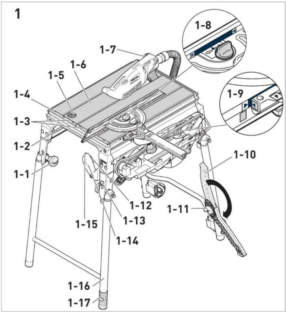
text_image
1 1-7 1-6 1-5 1-4 1-3 1-2 1-1 1-10 1-9 1-8 1-7 1-15 1-12 1-13 1-14 1-11 1-16 1-17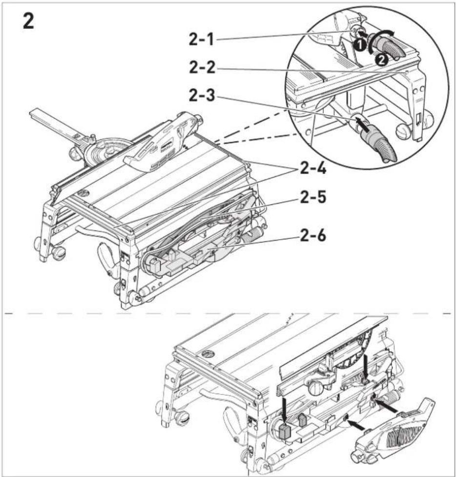
text_image
2 2-1 2-2 2-3 2-4 2-5 2-6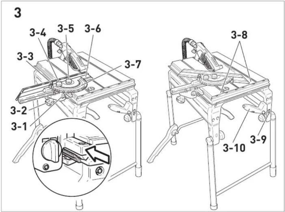
text_image
3 3-4 3-5 3-6 3-3 3-7 3-2 3-1 3-8 3-10 3-9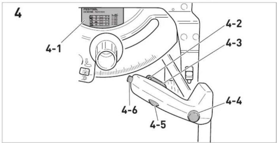
text_image
4 4-1 4-2 4-3 4-6 4-5 4-4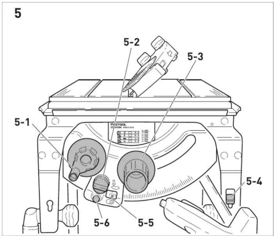
text_image
5 5-2 5-3 5-1 FISTOOL OF STONE PUCTING 5-4 5-6 5-5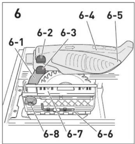
text_image
6 6-1 6-2 6-3 6-4 6-5 6-8 6-7 6-6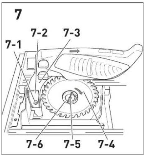
text_image
7 7-1 7-2 7-3 7-6 7-5 7-4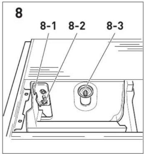
text_image
8 8-1 8-2 8-3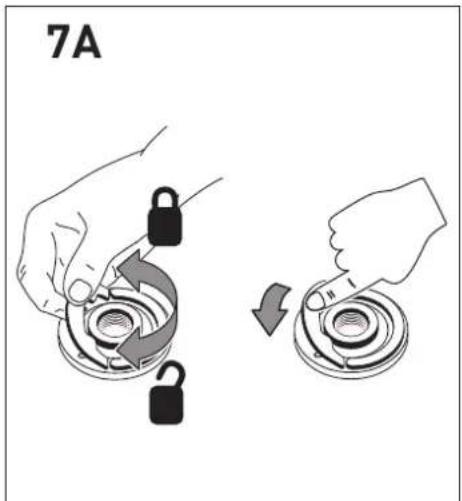
text_image
7A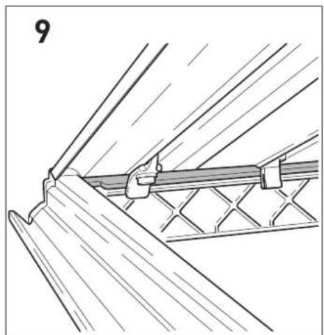
natural_image
Technical line drawing of a structural joint or bracket assembly (no text or symbols)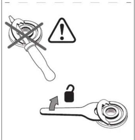
text_image
Safety warning icons including a wrench, warning symbol with exclamation mark, and lock mechanism with clockwise arrow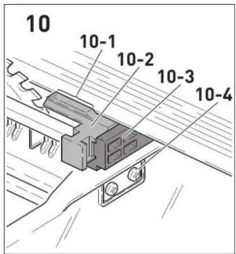
text_image
10 10-1 10-2 10-3 10-4
text_image
11 11-1 11-2 11-3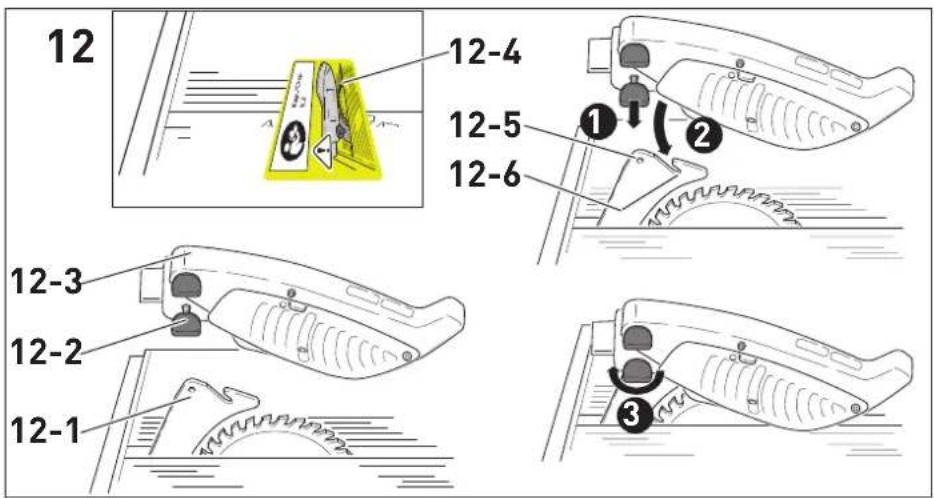
text_image
12 12-4 12-5 12-6 12-3 12-2 12-1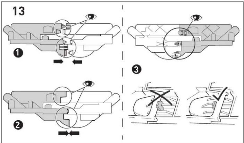
text_image
13 ① ② ③
text_image
14 ① ② ③
text_image
15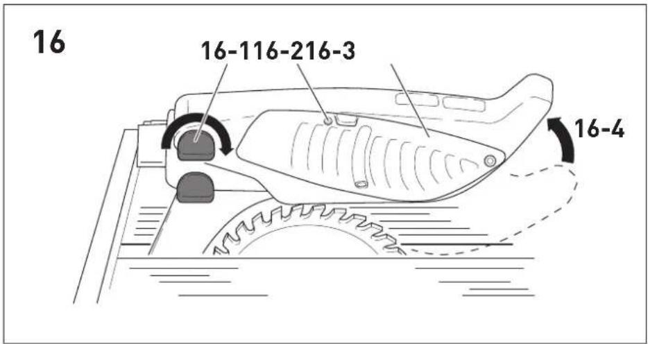
text_image
16 16-116-216-3 16-4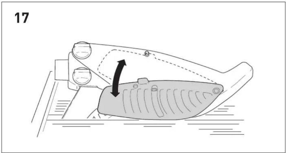
natural_image
Diagram of a mechanical component with a highlighted section and directional arrow (no text or symbols)festool.com/quickguide-CS50

en: EU Declaration of Conformity. We declare under sole responsibility that this product complies with all the relevant requirements in the following EU Directives, and following standards or normative documents were applied:
70565 Stuttgart, Germany
Approved Body Number: 0158
EC Type-examination Certificate Number: 4813048.24001
We as the manufacturer declare under our sole responsibility that the product(s) fulfill(s) all the relevant provisions of the following UK Regulations and are manufactured in accordance with the following designated standards:
S.I. 2008/1597 Supply of Machinery [Safety] Regulations 2008
S.I. 2016/1091 Electromagnetic Compatibility Regulations 2016
S.I. 2021/422 Restriction of the Use of Certain Hazardous Substances in Electrical and Electronic Equipment Regulations 2012
BS EN 62841-1: 2015 + AC:2015 + A11:2022,
BS EN 62841-3-1:2014 + AC:2015 + A11:2017 + A1:2021 + A12:2021,
BS EN 55014-1:2017 + A11:2020,
BS EN 55014-2:1997 + A1:2001 + A2:2008 + AC:1997,
BS EN 61000-3-2:2014,
BS EN 61000-3-3:2013,
BS EN IEC 63000:2018
UK Approved Body for UK Type-examination:
Technology International (Europe) Ltd.
56, Shrivenham Hundred Business Park
Shrivenham, Swindon. SN6 8TY
United Kingdom
Tel: (44) 1793 783137
Approved Body Number: 0673
UK Type-examination Certificate Number: TI(E) / SOMSR (08) - UKTE / 166 / 16072024
natural_image
Line drawing of two hands using a tool to cut a rectangular object (no text or symbols)natural_image
Line drawing of two hands using a tool to cut a piece of material on a cutting board (no text or symbols)1 Symbols....24
2 Safety warnings....24
3 Intended use....29
4 Technical data.... 29
5 Parts of the device....29
6 Commissioning....30
7 Settings....31
8 Working with the electric power tool......34
9 Transportation....35
10 Service and maintenance....35
11 Accessories.... 36
12 Environment....36
13 General information....36
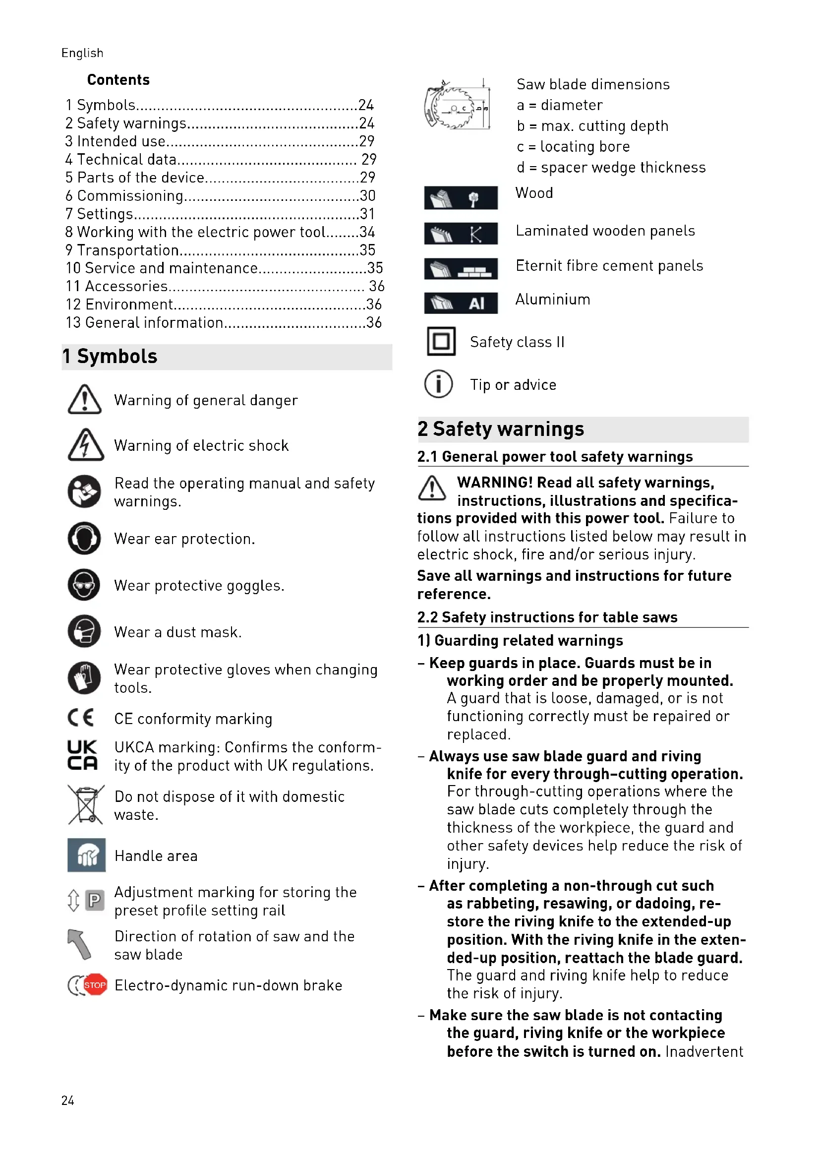
1 Symbols

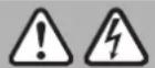
Warning of general danger

Warning of electric shock

Read the operating manual and safety warnings.

Wear ear protection.

Wear protective goggles.

Wear a dust mask.

Wear protective gloves when changing tools.

CE conformity marking

UKCA marking: Confirms the conformity of the product with UK regulations.

Do not dispose of it with domestic waste.

Handle area

Adjustment marking for storing the preset profile setting rail

Direction of rotation of saw and the saw blade

Electro-dynamic run-down brake
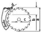
Saw blade dimensions
a = diameter
b = max. cutting depth
c = locating bore
d = spacer wedge thickness
Wood

Laminated wooden panels

Eternit fibre cement panels

Aluminium


Safety class II

Tip or advice
2 Safety warnings
2.1 General power tool safety warnings
WARNING! Read all safety warnings, instructions, illustrations and specifications provided with this power tool. Failure to follow all instructions listed below may result in electric shock, fire and/or serious injury.
Save all warnings and instructions for future reference.
2.2 Safety instructions for table saws
1) Guarding related warnings
- Keep guards in place. Guards must be in working order and be properly mounted. A guard that is loose, damaged, or is not functioning correctly must be repaired or replaced.
- Always use saw blade guard and riving knife for every through-cutting operation. For through-cutting operations where the saw blade cuts completely through the thickness of the workpiece, the guard and other safety devices help reduce the risk of injury.
- After completing a non-through cut such as rabbeting, resawing, or dadoing, re-store the riving knife to the extended-up position. With the riving knife in the extended-up position, reattach the blade guard. The guard and riving knife help to reduce the risk of injury.
- Make sure the saw blade is not contacting the guard, riving knife or the workpiece before the switch is turned on. Inadvertent
contact of these items with the saw blade could cause a hazardous condition.
- Adjust the riving knife as described in this instruction manual. Incorrect spacing, positioning and alignment can make the riving knife ineffective in reducing the likelihood of kickback.
- For the spacer wedge to be effective, it must be located in the sawing gap. For cuts in workpieces that are too short to allow the spacer wedge to engage, the spacer wedge is rendered ineffective. Under these conditions, a kickback cannot be prevented by the spacer wedge.
- Use the appropriate saw blade for the riving knife. For the riving knife to function properly, the saw blade diameter must match the appropriate riving knife and the body of the saw blade must be thinner than the thickness of the riving knife and the cutting width of the saw blade must be wider than the thickness of the riving knife.
2) Cutting procedures warnings

- DANGBR: Never place your fingers or hands in the vicinity or in line with the saw blade. A moment of inattention or a slip could direct your hand towards the saw blade and result in serious personal injury.
- Feed the workpiece into the saw blade only against the direction of rotation. Feeding the workpiece in the same direction that the saw blade is rotating above the table may result in the workpiece, and your hand, being pulled into the saw blade.
- Never use the mitre gauge to feed the workpiece when ripping and do not use the rip fence as a length stop when cross cutting with the mitre gauge. Guiding the workpiece with the rip fence and the mitre gauge at the same time increases the likelihood of saw blade binding and kickback.
- When ripping, always keep the workpiece in full contact with the fence and always apply the workpiece feeding force between the fence and the saw blade. Use a push stick when the distance between the fence and the saw blade is less than 150 mm, and use a push block when this distance is less than 50 mm. "Work helping" devices will keep your hand at a safe distance from the saw blade.
- Use only the push stick provided by the manufacturer or constructed in accord-
ance with the instructions. This push stick provides sufficient distance of the hand from the saw blade.
- Never use a damaged or cut push stick. A damaged or cut push stick may break causing your hand to slip into the saw blade.
- Do not perform any operation "freehand". Always use either the rip fence or the mitre gauge to position and guide the workpiece. "Freehand" means using your hands to support or guide the workpiece, in lieu of a rip fence or mitre gauge. Freehand sawing leads to misalignment, binding and kickback.
- Never reach around or over a rotating saw blade. Reaching for a workpiece may lead to accidental contact with the moving saw blade.
- Provide auxiliary workpiece support to the rear and/or sides of the saw table for long and/or wide workpieces to keep them level. A long and/or wide workpiece has a tendency to pivot on the table's edge, causing loss of control, saw blade binding and kick-back.
- Feed the workpiece evenly. Do not bend, twist or move the workpiece to the side. If the saw blade jams, switch the power tool off immediately, disconnect the mains plug and rectify the cause of the jam. The jamming of the saw blade by the workpiece can lead to kickbacks or engine jams.
- Do not remove pieces of cut-off material while the saw is running. The material may become trapped between the fence or inside the saw blade guard and the saw blade pulling your fingers into the saw blade. Turn the saw off and wait until the saw blade stops before removing material.
- Use an auxiliary fence in contact with the table top when ripping workpieces less than 2 mm thick. A thin workpiece may wedge under the rip fence and create a kickback.
3) Kickback causes and related warnings
Kickback is a sudden reaction of the workpiece due to a pinched, jammed saw blade or mis-aligned line of cut in the workpiece with respect to the saw blade or when a part of the workpiece binds between the saw blade and the rip fence or other fixed object.
Most frequently during kickback, the workpiece is lifted from the table by the rear portion of the
English
saw blade and is propelled towards the operator.
Kickback is the result of saw misuse and/or incorrect operating procedures or conditions and can be avoided by taking proper precautions as given below.
- Never stand directly in line with the saw blade. Always position your body on the same side of the saw blade as the fence. Kickback may propel the workpiece at high velocity towards anyone standing in front and in line with the saw blade.
- Never reach over or in back of the saw blade to pull or to support the workpiece. Accidental contact with the saw blade may occur or kickback may drag your fingers into the saw blade.
- Never hold and press the workpiece that is being cut off against the rotating saw blade. Pressing the workpiece being cut off against the saw blade will create a binding condition and kickback.
- Align the fence to be parallel with the saw blade. A misaligned fence will pinch the workpiece against the saw blade and create kickback.
- Use a featherboard to guide the workpiece against the table and fence when making non-through cuts such as rabbeting, dado-ing or resawing cuts. A featherboard helps to control the workpiece in the event of a kickback.
- Use extra caution when making a cut into blind areas of assembled workpieces. The protruding saw blade may cut objects that can cause kickback.
- Support large panels to minimise the risk of saw blade pinching and kickback. Large panels tend to sag under their own weight. Support(s) must be placed under all portions of the panel overhanging the table top.
- Use extra caution when cutting a workpiece that is twisted, knotted, warped or does not have a straight edge to guide it with a mitre gauge or along the fence. A warped, knotted, or twisted workpiece is unstable and causes misalignment of the kerf with the saw blade, binding and kick-back.
- Never cut more than one workpiece, stacked vertically or horizontally. The saw blade could pick up one or more pieces and cause kickback.
- When restarting the saw with the saw blade in the workpiece, centre the saw blade in the kerf so that the saw teeth are not engaged in the material. If the saw blade binds, it may lift up the workpiece and cause kickback when the saw is restarted.
- Keep saw blades clean, sharp, and with sufficient set. Never use warped saw blades or saw blades with cracked or broken teeth. Sharp and properly set saw blades minimise binding, stalling and kick-back.
4) Table saw operating procedure warnings
- Turn off the table saw and disconnect the battery pack when removing the table insert, changing the saw blade or making adjustments to the riving knife or saw blade guard, and when the machine is left unattended. Precautionary measures will avoid accidents.
- Never leave the table saw running unattended. Turn it off and don't leave the tool until it comes to a complete stop. An unattended running saw is an uncontrolled hazard.
- Locate the table saw in a well-lit and level area where you can maintain good footing and balance. It should be installed in an area that provides enough room to easily handle the size of your workpiece. Cramped, dark areas, and uneven slippery floors invite accidents.
- Frequently clean and remove sawdust from under the saw table and/or the dust collection device. Accumulated sawdust is combustible and may self-ignite.
- The table saw must be secured. A table saw that is not properly secured may move or tip over.
- Remove tools, wood scraps, etc. from the table before the table saw is turned on. Distraction or a potential jam can be dangerous.
- Always use saw blades with correct size and shape (diamond versus round) of ar-bour holes. Saw blades that do not match the mounting hardware of the saw will run off-centre, causing loss of control.
- Never use damaged or incorrect saw blade mounting means such as flanges, saw blade washers, bolts or nuts. These mounting means were specially designed
for your saw, for safe operation and optimum performance.
- Never stand on the table saw, do not use it as a stepping stool. Serious injury could occur if the tool is tipped or if the cutting tool is accidentally contacted.
- Make sure that the saw blade is installed to rotate in the proper direction. Do not use grinding wheels, wire brushes, or abrasive wheels on a table saw. Improper saw blade installation or use of accessories not recommended may cause serious injury.
2.3 Safety information for the saw blade
Usage
- The tool must be suitable for the material you are working on.
- The maximum speed specified on the saw blade must not be exceeded and the speed range must be adhered to.
- Proceed with extreme care when unpacking, packing and handling the tool (e.g. installing it in the machine). There is a risk of injury from extremely sharp cutting edges!
- When handling the tool, wearing safety gloves provides a more secure hold of the tool and further reduces the risk of injury.
- Circular saw blades with cracked bodies must be replaced. Repair is not permitted.
- WARNING! Do not use tools with visible cracks or blunt or damaged cutting edges.
Installation and mounting
- When assembling the tools, it must be ensured that the clamping takes place on the tool hub or the clamping surface of the tool, and that the cutting edges do not come into contact with other components.
- Tighten retaining screws and nuts using suitable keys, etc. and to the torque specified by the manufacturer.
- The clamping surfaces must be cleaned to remove contamination, grease, oil and water.
- Clamping screws must be tightened according to the manufacturer's instructions.
- Do not lengthen the key or tighten by hitting with a hammer.
- Only securely installed rings, e.g. rings that have been pressed in or those that are held in position by an adhesive bond, may be used to adjust the hole diameter of circular saw blades to the spindle diameter of the
machine. The use of loose rings is not permitted.
- Only transport the tool in suitable packaging - risk of injury!
- Only use the machine if all safety devices are in their correct positions, the machine is in good condition and has been well maintained.
Service and maintenance
- Repairs or resanding work must only be carried out by Festool customer service workshops or experts.
- The tool design must not be changed.
- Deresinify and clean the tool regularly (cleaning agent with pH between 4.5 and 8).
- Blunt edges can be resharpened on the clamping surface to a minimum cutting edge thickness of 1 mm.
2.4 Further safety instructions
- Operating personnel must have received adequate training in the use, set-up and operation of the power tool.
- Report faults on the power tool, including the separating guards or the tool, to maintenance staff immediately upon discovery. The power tool must not be used again until the fault has been eliminated.
- Wear suitable personal protective equipment: Ear protection, safety goggles, a dust mask for work that generates dust.
- Harmful/toxic dust may be produced during your work (e.g. paint containing lead, certain types of wood or metals). Contact with or inhalation of this dust may pose a risk for the operating personnel or persons in the vicinity. Comply with the safety regulations that apply in your country.
- Use suitable breathing protection to protect your health. In enclosed spaces, ensure that there is sufficient ventilation and connect a mobile dust extractor.
- Connect the power tool to a suitable dust extractor to minimise the release of dust. Set all elements for dust collection (extraction hoods, etc.) correctly.
- When sawing wood, connect the power tool to a dust extractor corresponding to EN 60335-2-69, dust class M.
- To minimise noise, the tool must be sharpened and all noise-reducing elements (covers, etc.) must be properly adjusted.
English
- When sawing, adopt the correct working position:
- At the front on the side of the operator;
- Head-on to the saw;
- Beside the line of cut.
- Use the push stick to safely guide the workpiece past the saw blade.
- When not in use, store the push stick in the accessory holder provided on the power tool.
- Always use the supplied spacer wedge and the protective cover. Ensure that they are set correctly as described in the operating instructions. If the spacer wedge is set incorrectly and components that are required for safety reasons (such as the protective covers) are removed, this may result in serious injuries.
- Before commencing work, check that the protective cover and splinter guard can move freely and are resting on the table.
- The safety equipment must be re-installed immediately after work that requires the protective cover to be removed, see section 6.2.
- Cutting rebates or grooves is only permitted when a suitable protective device has been fitted, e.g. a protective tunnel over the saw table.
- Do not use circular saws for cutting slots (grooves in workpiece).
- When cutting metal, switch on the saw using a residual-current circuit breaker.
- Use a suitable device to support long workpieces and ensure that they are horizontal.
- Pull the plug from the socket before changing tools and rectifying faults such as removing trapped splinters.
- Do not remove offcuts or other workpiece parts from the cutting area while the power tool is still running or before the saw blade stops moving.
- If the saw blade is jammed, switch the power tool off immediately and disconnect the mains plug. Do not remove the jammed workpiece until you have done this.
- While transporting the power tool, the top protective cover must cover the top section of the saw blade.
- Do not use the upper protective cover as a handle for transportation.
- Use only original accessories and aids from Festool.
- Do not use your own aids e.g. push stick, rulers, etc.
- To prevent the saw blade from overheating or the plastic from melting, set the correct speed for the cutting material and do not use excess pressure when cutting.
- Check the plug and cable on a regular basis and, if they are damaged, have them replaced by an authorised customer service workshop.
- Only for AS/NZS: The tool shall always be supplied via residual current device with a rated residual current of 30 mA or less.
2.5 Aluminium processing
When processing aluminium, the following measures must be taken for safety reasons:

- Wear protective goggles.
- Install an upstream residual-current circuit breaker (RCD, PRCD).
- Connect the power tool to a suitable dust extractor with an antistatic suction hose.
- Regularly clean dust deposits from the motor housing on the power tool.
- Use a saw blade suitable for cutting aluminium.
- When sawing panels, they must be lubricated with petroleum, although thin-walled profiles (up to 3 mm) can be sawed without lubrication.
2.6 Other risks
In spite of compliance with all relevant design regulations, dangers may still present themselves when the power tool is operated, e.g.:
- Touching rotating parts.
- Touching live parts while the housing is open.
- Workpiece parts being thrown off.
- Parts of damaged tools being thrown off.
- Noise emissions
- Dust emissions
2.7 Emission levels
The levels determined in accordance with EN 62841 are typically:
Sound pressure level L _PA = 87 dB(A)
Sound power level L _WA = 101 dB(A)
Uncertainty K = 3 dB


CAUTION
Noise emissions created while working with the power tool may damage your hearing.
▶ Always use ear protection.
The specified noise emission values
– have been measured in accordance with a standardised test procedure, can be used to compare one power tool with another,
- and can also be used for a provisional assessment of the load.

CAUTION
The emission values may deviate from the specified values. This is dependent on how the tool is used and the type of workpiece being machined.
▶ Assess the actual load during the entire operating cycle.
▶ Depending on the actual load, suitable protective measures must be defined in order to protect the operator.
3 Intended use
The PRECISIO is designed as a transportable power tool for sawing wood, plastics, panel materials made of wood and similar materials.
When fitted with the special saw blades for aluminium that are offered by Festool, these power tools can also be used for sawing aluminium.
Materials containing asbestos must NOT be processed.
Do not use cutting or abrasive wheels.

The user is liable for improper or non-in-tended use.
3.1 Saw blades
Only use saw blades with the following dimensions:
– Saw blades according to EN 847-1
- Saw blade diameter 190 mm
- Cutting width 2.6 mm
- Locating bore 20 mm/30 mm
- Standard blade thickness < 2 mm
- Suitable for speeds of up to 4200 min ^-1
Festool saw blades comply with EN 847-1.
Only saw materials for which the saw blade in question has been designed.
4 Technical data
| Table saw and circular trimming saw | CS 50 EBG/ CS 50 EG |
| Power consumption 1200 W | |
| No-load speed 1600-4200 min | -1 |
| Cutting depth at -2°/47° | 0-52 mm/0-37 mm |
| Inclination -2°-47° | |
| Max. cutting length 300 mm | |
| Saw blade (diameter x cutting width) | 190 x 2.6 mm |
| Locating bore 20 mm/30 mm | |
| Standard blade thickness < 2 mm | |
| Table dimensions (length x width) | 600 x 400 mm |
| Table height (legs unfol-ded/legs folded away) | 900 mm/375 mm |
| Weight without legs 21 kg | |
| Weight with legs 25 kg |
5 Parts of the device
[1-1] Rotary knobs for unfolding and folding the legs
[1-2] Guide rods
[1-3] Scale
[1-4] Scale screw
[1-5] Table insert lock
[1-6] Table insert
[1-7] Protective cover
[1-8] Position marking for preset profile setting rail
[1-9] Position marking for stop
[1-10] Additional feet
[1-11] Screws for additional feet
[1-12] On/off switch
[1-13] Switch
[1-14] Handle
[1-15] Locking switch
[1-16] Legs
[1-17] End cap for legs
The specified illustrations appear at the beginning of the operating manual.
6 Commissioning
6.1 Setting up the PRECISION [1]
![FESTOOL PRECISIO CS 50 EBG - Setting up the PRECISION [1] - 1](/content/2026/04/630448/images/a1e87bb156778f56c76a5107b68eacff041454bc574d5ab0c5c13eedea26e838.jpg)
WARNING
Risk of accidents
Power tool tips over on uneven surface.
- Ensure that the power tool is securely positioned. The surface underneath the machine must be level, in good condition and free of loose objects (e.g. chips and offcuts).
The power tool can be set up with or without the legs unfolded.
- When unpacking the power tool, remove the transport inserts.
▶ Open the four rotary knobs [1-1] to unfold the legs [1-16] all the way.
▶ Unfold the legs.
▶ Screw in the four rotary knobs tight again.
▶ To ensure that the power tool is standing securely, the length of a leg can be changed by turning the end cap [1-17] until the machine stands securely.
6.2 Before initial commissioning [12] [15]
Fitting the protective cover
▶ Remove the yellow safety sticker [12-4].
- Set the saw to maximum cutting depth and the mitre to 0°.
▶ Pull the spacer wedge [12-1] into the upper position.
Take hold of the protective cover [12-3] and completely unscrew the screw [12-2].
▶ Face the protective cover on the spacer wedge. Insert the lengthwise pin situated in the protective cover into the groove [12-6] on the spacer wedge, and put the screw through the hole [12-5] in the spacer wedge.
▶ Tighten the screw.
Installation of the preset profile setting rail
▶ Push the handle of the preset profile setting rail into the zero position.
▶ Tighten the screw [3-1] and attach the pre-set profile setting rail to the table.
6.3 Scope of application [1] [3]
The power tool can be used as a table saw (see section 8.2) or as a circular trimming saw (see section 8.3).
Table saw
▶ Set the switch [1-13] to the lower position.
▶ Swivel the handle [1-14] downwards and use it to pull the saw unit forwards until it clicks into place.
The saw unit is now in a central position on the table and the power tool can be used as a table saw.
When the handle [3-10] is swivelled downwards, it can move the saw unit backwards and forwards for making cuts. The backwards motion is supported by a spring force.
Circular trimming saw
The saw unit is now in a central position on the table and the power tool can be used as a table saw.
▶ Set the switch [3-9] to the upper position.
When the handle [3-10] is swivelled downwards, it can move the saw unit backwards and forwards for making cuts. The backwards motion is supported by a spring force.
6.4 Dust extraction

WARNING
Health hazard posed by dust
▶ Always work with an extractor.
▶ Comply with national regulations.
- When sawing carcinogenic materials, always connect a suitable extraction mobile in accordance with national regulations. Do not use the chip collection bag.
The power tool has two vacuum connections: Upper protective cover with bayonet coupling [2-1] with Dia. 27 mm and lower protective cover [2-3] with Dia. 35 mm.
The dust extraction set (included in the delivery of CS 50 EB) connects the two vacuum connections together so that a Festool mobile dust extractor can be connected.
Static charge may occur when sawing (e.g. MDF). If this is the case, work with a mobile dust extractor and an antistatic suction hose.
CAUTION! If an anti-static suction hose is not used, static charge may occur. The user may receive an electric shock and the electronics of the power tool may be damaged.
6.5 Electrical connection and commissioning
WARNING
Unauthorised voltage or frequency Risk of accidents
▶ The mains voltage and the frequency of the power source must correspond to the specifications on the name plate.
▶ In North America, only Festool power tools with the voltage specifications 120 V/60 Hz may be used.
▶ We recommend using a 16 A fuse because of the performance of the motor.
▶ Before each use of the machine, check the cable and the plug. Any damage must only be rectified by a specialist workshop.
- For use outdoors, only use the approved extension cable and cable connections.
To switch on, press the ON/OFF switch [4-3] and the locking switch [4-6] at the same time. The power tool will run as long as the ON/OFF switch remains pressed.
For continuous operation after switching on, first release the ON/OFF switch and then release the locking switch.
To switch continuous operation off, either press the ON/OFF switch again and then release it, or press the red switch [4-4] .
To prevent the device from being switched on without authorisation, a U-lock [4-2] can be fitted to the ON/OFF switch hole.
6.6 Additional feet\*
Always use the additional feet* with a length extension table, width extension table or sliding table.
▶ Loosen the clamping screw [1-11], swivel out the additional foot [1-10] until it is supported on the floor.
▶ Retighten the clamping screw
* Accessories shown or described are not always included in the scope of delivery.
6.7 Installing the accessory holder [13]
When connecting the two individual parts, make sure that the tabs on the latches fit together exactly and lock in place. Also check the reverse of the accessory holder to make sure the latches are in the correct position in the holding brackets.
6.8 Mitre rip cuts
For mitre rip cuts, fit the preset profile setting rail on the right-hand side of the table, see section 6.2.
6.9 Switching on the machine when cutting metal
When cutting metal, switch on the saw using a residual-current circuit breaker.
7 Settings

WARNING
Risk of injury
▶ Pull out the mains plug before you carry out any work on the power tool.
To make adjustments easier, the saw unit can be locked in place in the central position: Pull the saw unit forward up to the stop and set the switch [5-4] to the lower position.
The saw blade can be swivelled between 0^ and 45^
7.1 Setting the speed
The speed can be adjusted in six settings using the adjusting wheel, depending on the work-piece requirements.
| Setting | n_0 [rpm] |
| 1 ~ 1600 | |
| 2 ~ 2100 | |
| 3 ~ 2600 | |
| 4 ~ 3100 | |
| 5 ~ 3600 | |
| 6 ~ 4200 |
7.2 Setting the cutting height
The cutting height can be continuously adjusted (0–52 mm when the saw blade is set to 90°) by turning the crank [5-1].
7.3 Mitre angle
The saw blade can be swivelled between 0^ and 45^
▶ Open the rotary knob [5-2].
▶ Set the mitre angle with the help of the scale [5-5] by turning the handle [5-3].
▶ Close the rotary knob.
The saw blade can be tilted 2^ beyond the two end positions for precision trimming work (undercuts on abutting edges). To do this, press the button [5-6] in the end position; then the
English
saw blade can be swivelled to -2^ or 47^ . After swivelling it back, the two end positions become active again.
7.4 Changing the tool

WARNING
Risk of injury
Safety information for the FastFix clamping nut [7A].
- Close the lift-up handle after tightening the clamp.
▶ Only tighten or loosen the FastFix clamping nut by hand. Never use a screwdriver, pliers or any other tool to loosen or tighten the lift-up handle.
If the nut can no longer be loosened by hand, it should only be loosened with a face wrench.
▶ If the lift-up handle is loose or damaged, the FastFix nut must no longer be used under any circumstances.
![FESTOOL PRECISIO CS 50 EBG - Safety information for the FastFix clamping nut [7A]. - 1](/content/2026/04/630448/images/c55834395544f58be157c8edcf21a9f9db66ac15e2a08bbfba98d8a971d7f611.jpg)
WARNING
Risk of injury
▶ Because of the special holder, only saw blades available for this power tool from Festool with a diameter of may be used.

CAUTION
Risk of injury from hot and sharp tool.
▶ Do not use any blunt or faulty tools.
▶ Wear protective gloves when handling a tool.
▶ Open the lock [1-5] and remove the table insert [1-6] upwards.
▶ Open the lock [6-8] and swivel the saw blade cover [6-7] downwards. This automatically locks the tool spindle.
▶ Pull the lever [7-6] and turn it clockwise (left-hand thread) to open the FastFix quick release [7-7] .
- Change the tool while making sure that: - The FastFix quick release, flange [8-3] and saw blade must be clean. - The direction of rotation on the saw blade [7-5] must correspond to the direction of rotation of the power tool [7-4]. - The saw blade is placed in the middle of the flange and then turned until the contours of the flange and the hole of the saw blade click into place.
▶ Tighten the FastFix quick release anticlockwise and pull the lever.
▶ Swivel the saw blade cover upwards and close the lock.
▶ Rotate the saw blade twice to make sure that it can move freely.
▶ Insert the table insert with the rear edge [9] first and close the lock.
7.5 Adjusting the spacer wedge

WARNING
Risk of injury
▶ Never work without a spacer wedge.
Set the spacer wedge [7-3] so that the distance to the saw blade's sprocket is 3–5 mm.
▶ Use the hex key [6-6] to unscrew the screw [7-1] and remove it together with the clamping element [7-2] .
▶ After unscrewing both screws [8-2], the guide piece [8-1] can be moved vertically to adjust the distance between the spacer wedge and saw blade.
▶ After performing the adjustment, refit the spacer wedge and clamping element and retighten all the screws.
7.6 Adjusting the stop [1] [3]
The supplied stop can be attached to all four sides of the power tool. The fence can be adjusted in the following ways: The fence can be used as a stopper or as a cross stop or angle stop.
Stopper:
▶ Loosen the screw [3-4] and lift the fixing pin [3-3], adjust the angle to 0^ with the help of the scale, lock the fixing pin again and tighten the screw.
▶ Loosen the screw [3-5] and adjust the rail [3-6] in such a way that the triangular arrow lies within the green sticker, see details [1-8]. Then tighten the screw.
▶ Push the preset profile setting rail into the groove on the side of the table ([3] detail). Slide it until the preset profile setting rail's handle covers the green marked area on the side of the table, see detail [1-9]. Then tighten the screw [3-2].
▶ Loosen the screw [3-1], set the desired cutting width and retighten the screw.
The preset profile setting rail can be used as a high or low stopper. To do this, the rail is inserted either upright or flat.
The low stopper is used to prevent a collision with the saw blade protective cover, e.g. in the case of mitre cuts with a saw blade swivelled to 45^ .
Cross stop and angle stop:
▶ Slide the preset profile setting rail into the groove in the table and tighten the screw [3-2].
▶ Loosen the screw [3-4] and lift the fixing pin, adjust to the desired angle on the scale (the fixing pin will click into place in the most common angle settings) and then re-tighten the screw.
▶ Loosen the screw [3-5] and adjust the rail so that it does not reach into the cutting plane, and then tighten the screw.

Make sure that all rotary knobs on the workpiece are tightened before starting work. The should always be used in a fixed position must not be used to push the workpiece.
Fold the preset profile setting rail into the zero position and place it in the accessory holder [2-6] when not in use [2].
7.7 Scale for cutting width
The two scales [1-3] indicate the cutting width of rip cuts.
If needed, the scales can be readjusted after loosening the screws [1-4].
7.8 Installing the splinter guard
The splinter guard [10-2] prevents splinters on the lower cutting edge of the workpiece. The splinter guard can be used at all mitre angles, but a separate splinter guard must be installed and cut into for each angle:
▶ Set the saw blade to the minimum cutting height.
▶ Open the lock [1-5] and remove the table insert [1-6] upwards.
▶ Open the lock [6-8] and swivel the saw blade cover [6-7] downwards. This automatically locks the tool spindle
▶ Push the splinter guard onto the side of the retainer [10-3] as far as it will go.
▶ Swivel the saw blade cover upwards and close the lock.
▶ Insert the table insert with the rear edge [9] first and close the lock.
- Switch on the power tool and slowly move the saw blade up to the maximum cutting height – this cuts into the splinter guard.
The raised section [10-1] of the splinter guard should protrude slightly (by approx. 0.3 mm) over the edge of the table so that it functions more effectively. The height of the retainer can also be adjusted after loosening the two screws [10-4] .
7.9 Adjusting the protective cover
To adjust the stops, the protective cover can be locked in place in the upper position.
- Lock the lateral splinter guard [16-3] with the catch [16-2] in the upper position.
▶ Lift the protective cover into the top position [16-4] and tighten the screw [16-1]
▶ After adjusting the stops, loosen the screw again and unhook the side splinter guard. Note: The protective cover and the splinter guard must lie freely on the plate [17]. - When not in use, attach the protective cover to the accessory holder [2-6].
7.10 Smooth start-up
The electronically controlled smooth start-up function ensures that the power tool starts up smoothly.
7.11 Speed regulator
You can continuously adjust the speed within the speed range using the adjusting wheel. This enables you to optimise the speed to suit the respective material. Please also note the specifications on the grinding tools.
7.12 Overload safety device
The power supply is restricted if the power tool is overloaded to extremes. The power supply is disconnected completely if the motor jams for some time. You will need to remove the load and/or switch off the power tool before you can use it again.
7.13 Temperature cut-out
The power supply is restricted and the speed reduced if the motor exceeds a certain temperature. The power tool continues operating at reduced power to allow the ventilator to cool the motor quickly. The power tool starts up again automatically once the motor has cooled sufficiently.
7.14 Brake
The saw comes with an electronic brake. The saw blade is stopped electronically within approximately two seconds of switching off the machine.
7.15 Restart protection
The built-in restart protection prevents the power tool from starting up again automatically if the power is disconnected during continuous
English
use. To put the power tool back into operation, it must first be switched off and then on again.
8 Working with the electric power tool
8.1 Safe working

When working on the machine, observe all of the safety warnings that are listed at the start as well as the following rules:
- Ensure that the upper protective cover [6-4] and the splinter guard [6-5] are resting on the workpiece and move freely.
- Do not work with oversized and overly heavy workpieces that could damage the tool. The protective cover determines the maximum height of the workpiece.
- For safety reasons, NEVER work without an upper protective cover [6-4] fitted (except for concealed cuts).
- Perform measurement settings when the power tool is at a standstill.
8.2 Use as a table saw [1] [3]
Rip cuts
▶ Place the saw blade on the centre of the table, see section 6.3.
▶ Use the preset profile setting rail as a lengthwise ruler to guide the workpiece.
▶ The cutting width can be adjusted using the scales.
▶ Guide the workpiece by hand. Keep your arms away from the saw blade's centre line.
▶ Use the push stick [2-5] to guide the workpiece past the saw blade.
▶ Place the push stick in the accessory holder [2-6] when not in use.
Angled cuts
▶ For angled cuts, adjust the mitre angle of the saw blade, see section 7.3.
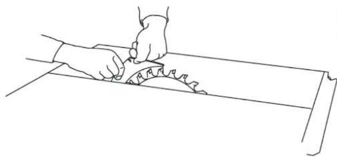
Concealed cuts
If the protective cover has been removed, the spacer wedge can be adjusted by firmly pulling by two locking positions. The spacer wedge is used in the upper locking position for all applications, except for concealed cuts.
Before starting work
▶ Remove the upper protective cover [6-4].
▶ Move the spacer wedge [7-3] into the lower locking position by pushing it down firmly.
natural_image
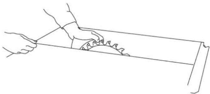
Line drawing of two hands using a tool to cut a rectangular object (no text or symbols)Creating concealed cuts
- When executing concealed cuts, ensure that the tool is guided precisely. To do this, push the workpiece down firmly onto the table. Select the cutting sequence so that the workpiece side already cut out is not the stop side (risk of kickback).
Rebating
▶ Set the cutting depth and stop of the first side of the rebate.
- Carry out the first saw cut of the rebate by guiding the workpiece by hand. Keep your arms away from the saw blade's centre line.
▶ Use the push stick [2-5] to guide the workpiece past the saw blade.
▶ Turn the workpiece.
▶ Set the cutting depth and stop of the second side of the rebate.
▶ Make the second saw cut of the rebate.
▶ Use the push stick to guide the workpiece past the saw blade.
Rebating on workpieces ≤ 12 mm with a circular trimming saw (with the saw blade locked)
▶ Use the stop as a cross stop.
▶ Follow the instructions for cross cuts, see section 8.3.

NEVER use the stop as a stopper when rebating on the short side.
Grooving
▶ Adjust the cutting depth on the saw blade.
▶ Use the stop as a guide.
▶ Guide the workpiece by hand. Keep your arms away from the saw blade's centre line.
▶ Use the push stick [2-5] to guide the workpiece past the saw blade.
▶ Repeat the process until the required grooving depth is achieved.
After finishing work
▶ After making concealed cuts, return the spacer wedge [7-3] to the upper position and attach the protective cover [6-4].
natural_image
Line drawing of two hands using a tool to cut a saw blade (no text or symbols)Complicated concealed cut processes,
▶ e.g. plunge sawing, resawing, groove cutting, profile routing and fluting, are not permitted.
Featherboard
NOTICE
▶ Use a featherboard for concealed cuts. Fit the featherboard on the stop and the table so that the featherboard pushes the workpiece down firmly onto the plate during cutting. Featherboards are not included in the scope of delivery.
Rip cuts with inclination
▶ Only use the left stop when making longitudinal cuts at an angle in material with an edge length of ≤slant 150 mm. This creates more space between the stop and the saw blade.
8.3 Use as a circular trimming saw [3]
Cross cuts
▶ Place the saw blade in the back table position, see section 6.3.
▶ Use the preset profile setting rail as a crosswise or angle ruler to position the workpiece and hold it in place. Fastening clamps (not included in delivery) can be inserted into the grooves [3-8] to secure the workpiece. To perform the saw cut, swivel the handle [3-10] downwards and use it to pull the saw unit forwards.
▶ After completing the cut, move the saw unit right back to its starting position before the workpiece can be removed from the preset profile setting rail.
Angled cuts
For angled cuts, adjust the mitre angle of the saw blade, see section 7.3. The preset profile setting rail is on the right-hand side of the table.
▶ For mitre cuts, adjust the preset profile setting rail, see section 7.6.
8.4 Workpiece holder
▶ Place the push stick [2-5] in the accessory holder [2-6] when not in use.
9 Transportation

CAUTION
Risk of injury!
The power tool may slip out of your hands when you are carrying it.
▶ Always carry the power tool with both hands, using the gripping surfaces [2-4] provided on both sides of the power tool.
▶ Click the saw unit into place in the zero position.
▶ Remove all attachments from the saw and wind the cable around the cable holder.
▶ Fold in the legs.
For transport over short distances, two of the power tool's leg ends are equipped with transport rollers.
▶ Hold the tool in the handle area [2-4] and pull it to the desired position.
10 Service and maintenance
WARNING
Risk of injury, electric shock
▶ Always pull the mains plug from the socket before performing any servicing and maintenance work.
▶ All maintenance and repair work which requires the housing to be opened should always be carried out by an authorised service workshop.
Customer service and repairs must only be carried out by the manufacturer or service workshops. You must only use original Festool spare parts.
Further information: www.festool.co.uk/service
The power tool is equipped with special self-disconnecting carbon brushes. If they wear out, the power supply is disconnected automatically and the machine stops. Maintain the power tool regularly to make sure it functions properly:
▶ Use an extractor to remove dust deposits.
- Keep the guide rods [1-2] clean and grease them regularly.
▶ Replace a worn or damaged table insert.
▶ Use the slide [11-1] to open the flap [11-3] in order to remove offcuts from the lower
English
protective cover. To remove larger deposits, the flap can be completely opened by un-screwing the screw [11-2]. The flap must be closed again prior to use.
- Wind the power cable onto the accessory holder [2-6] once the work is complete.
▶ A damper allows the saw unit to retract evenly along the entire cutting length. If this is not the case, the damper can be adjusted using the hole [2-2].
▶ If it becomes necessary to replace the power cable, this must be carried out by the manufacturer or the service team in order to ensure that no hazards arise.
▶ Damaged safety devices and components must be repaired or replaced in a recognised specialist workshop, unless otherwise indicated in the operating instructions.
11 Accessories
You can find the PO numbers for accessories and tools under www.festool.co.uk.
12 Environment

Do not dispose of the device in the household waste! Recycle devices, accessories and packaging. Observe applicable national regulations.
In accordance with the European Directive on waste electrical and electronic equipment and implementation in national law, used electrical devices must be collected separately and handed in for environmentally friendly recycling.
Information on the collection points can be viewed at www.festool.com/environment.
Information on critical materials:
www.festool.co.uk/reach
13 General information
Imported into the UK by
Festool UK Ltd
1 Anglo Saxon Way
Bury St Edmunds
IP30 9XH
Great Britain
Sommaire
natural_image
Line drawing of two hands using a tool to cut a rectangular object (no text or symbols)natural_image
Line drawing of two hands using a tool to cut a saw (no text or symbols present)natural_image
Line drawing of two hands using a tool to cut a cylindrical object (no text or symbols)natural_image
Line drawing of two hands using a tool to cut a saw blade on a wooden surface (no text or symbols)natural_image
Line drawing of two hands using a tool to cut a saw (no text or symbols)natural_image
Line drawing of two hands using a tool to cut a saw blade (no text or symbols)natural_image
Line drawing of two hands using a tool to cut a rectangular object (no text or symbols)natural_image
Line drawing of two hands cutting a saw blade on a wooden surface (no text or symbols)2.5 Aluminiumbearbetning
natural_image
Line drawings showing two hand positions on a metal bar, one holding a saw and the other handling a workpiece (no text or symbols)Såga dolda snitt
natural_image
Line drawing of two hands using a tool to cut a rectangular object (no text or symbols)natural_image
Line drawing of two hands using a saw to cut a circular saw (no text or symbols)natural_image
Line drawing of two hands using a tool to cut a rectangular object (no text or symbols)Ikke-gennemgående snit
natural_image
Line drawing of two hands using a tool to cut a saw blade (no text or symbols)7.1 Stille inn turtallet
natural_image
Line drawing of two hands using a tool to cut a rectangular object (no text or symbols)Lage skjulte kutt
natural_image
Line drawing of a hand using a tool to cut a saw blade (no text or symbols)natural_image
Line drawing of two hands using a tool to cut a rectangular object (no text or symbols)natural_image
Line drawing of a hand using a saw to cut a circular saw (no text or symbols)Processos de cortes encobertos complicados
6.1 Instalace PRECISIO [1]
![FESTOOL PRECISIO CS 50 EBG - Instalace PRECISIO [1] - 1](/content/2026/04/630448/images/3f4b3be844a89d739c8eb458013d7858d91b937a0d6e28a3f86b20f2885631c0.jpg)