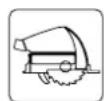
TSV 60 KEBQ - Saw FESTOOL - Free user manual and instructions
Find the device manual for free TSV 60 KEBQ FESTOOL in PDF.
| Product type | Plunge saw with pre-scoring device |
| Brand | Festool |
| Model | TSV 60 KEBQ |
| Power consumption | 1500 W (main unit); 190 W (pre-scoring device) |
| No-load speed | 3000 - 6800 min⁻¹ (main unit); 22000 min⁻¹ (pre-scoring) |
| Cutting depth at 0° | 0 - 62 mm (without guide rail); max. 57 mm (with FS guide rail) |
| Cutting depth at 45° | 0 - 45 mm |
| Bevel position | 0° to 45° |
| Saw blade dimensions | 168 x 1.8 x 20 mm (diameter x kerf width x bore) |
| Weight (without cable) | 6 kg (according to EPTA 01:2014) |
| Device dimensions (L x W x H) | 414 x 180 x 259 mm |
| Power supply | Mains, detachable cable (plug-it) |
| KickbackStop function | Yes, with detection finger and rapid brake |
| Electronic brake | Yes, stopping time ~2 s (main unit) |
| Pre-scoring device | Yes, 47 mm blade, adjustable in width and offset |
| Extraction connection | Diameter 27/32/36 mm |
| Sound pressure level | LpA = 90 dB(A) |
| Sound power level | LwA = 101 dB(A) |
| Vibration (wood/metal) | < 2.5 m/s² |
| Maintenance and cleaning | Regularly clean the ventilation slots, detection unit, and clamping surfaces; use dry compressed air |
| Safety | Protective guard, anti-kickback detection finger, electronic brake, overload and thermal protection |
| Spare parts and repairability | Festool original parts only; repair by authorized service center; data chip for diagnostics |
| Compatible accessories | FS guide rails, FS-RSP anti-kickback stop, angle stops, STM 1800 mobile table, MFT 3 |
Frequently Asked Questions - TSV 60 KEBQ FESTOOL
User questions about TSV 60 KEBQ FESTOOL
0 question about this device. Answer the ones you know or ask your own.
Ask a new question about this device
Download the instructions for your Saw in PDF format for free! Find your manual TSV 60 KEBQ - FESTOOL and take your electronic device back in hand. On this page are published all the documents necessary for the use of your device. TSV 60 KEBQ by FESTOOL.
USER MANUAL TSV 60 KEBQ FESTOOL
en Original Instructions - Plunge-cut saw 23
TSV 60 KEBQ TSV 60 KEB
natural_image
Festool industrial cutting cutter with green and black blade assembly (no visible text or symbols)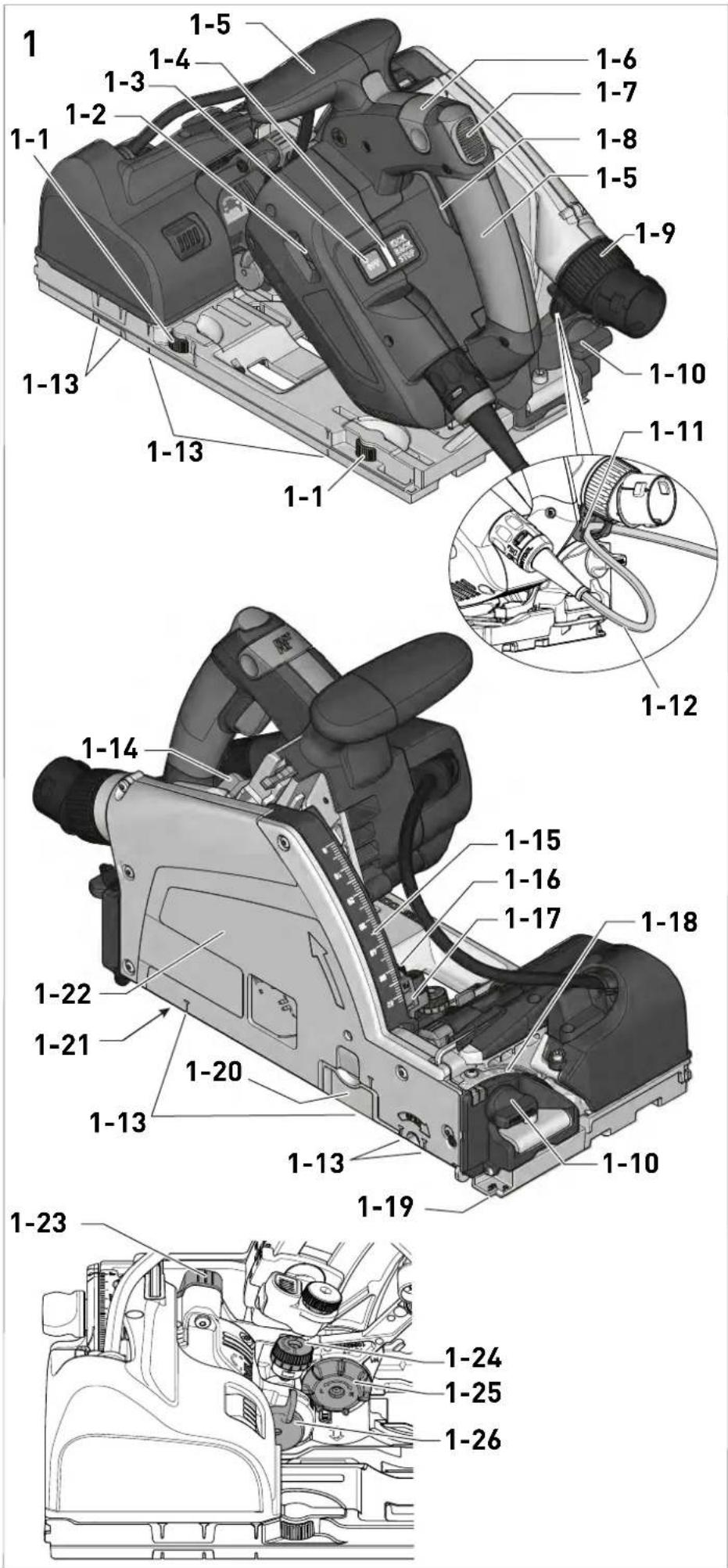
text_image
1 1-5 1-4 1-3 1-2 1-1 1-13 1-13 1-1 1-6 1-7 1-8 1-5 1-9 1-10 1-11 1-12 1-14 1-15 1-16 1-17 1-18 1-22 1-21 1-20 1-13 1-13 1-10 1-19 1-23 1-24 1-25 1-26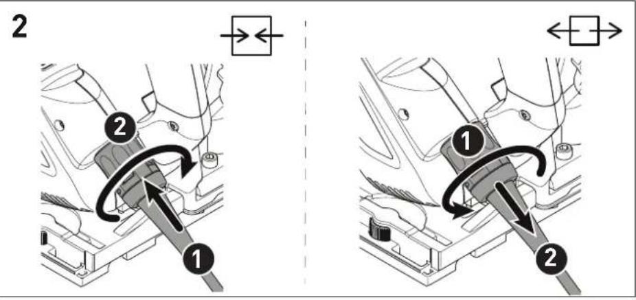
text_image
2 1 2 1 2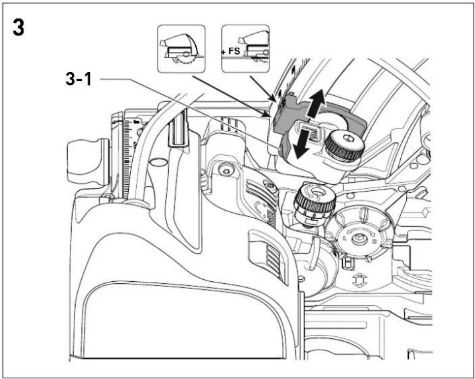
text_image
3 3-1 FS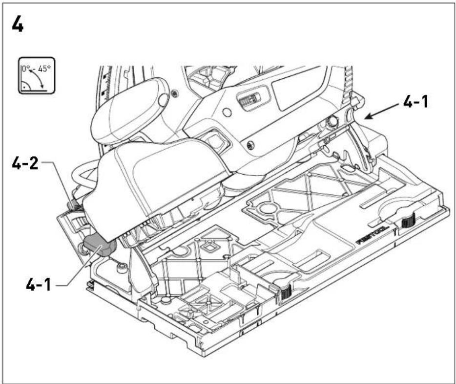
text_image
4 10° - 45° 4-1 4-2 4-1
text_image
5 5-2 5-5 5-6 5-7 5-8 5-4 5-3 5-2 5-1 5-9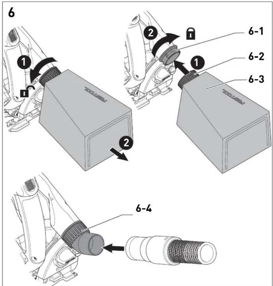
text_image
6 1 2 6-1 6-2 6-3 6-47
natural_image
Mechanical assembly diagram showing gear and valve components (no text or labels)ON
OFF
8
text_image
ON OFF 8-1ON
OFF
9
natural_image
Mechanical assembly diagram showing internal components with no visible text or symbols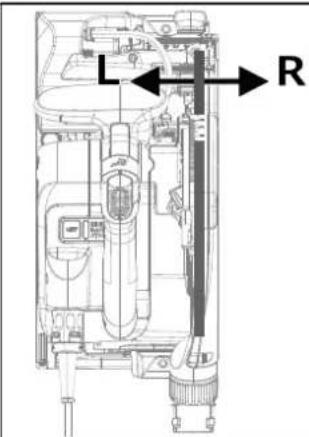
text_image
L R10
text_image
10-1
text_image
Diagram illustrating three states of a mechanical or electrical component with directional arrows and symbols (×, -, ✓, +)
We as the manufacturer declare under our sole responsibility that the product(s) fulfill(s) all the relevant provisions of the following UK Regulations and are manufactured in accordance with the following designated standards:
S.I. 2008/1597 Supply of Machinery [Safety] Regulations 2008
S.I. 2016/1091 Electromagnetic Compatibility Regulations 2016
S.I. 2012/3032 Restriction of the Use of Certain Hazardous Substances in Electrical and Electronic Equipment Regulations 2012
BS EN 62841-1:2015
BS EN 62841-2-5:2014
BS EN 55014-1:2017 + A11:2020
BS EN 55014-2:2015
BS EN 61000-3-2:2014
BS EN 61000-3-3:2013
BS EN IEC 63000:2018

d on behalf of and in name of
Festool GmbH
Wertstr. 20, 73240 Wendlingen, GERMANY
Place and date of declaration: Wendlingen, 2023-02-15

text_image
ppa. 1382Markus Stark
Head of Product Development

text_image
i.v. c. aChristian Bader
Head of Development Functions
^11 in the specified serial number range (S-Nr.) from 40000000 - 49999999
Tauchsäge
Seriennummer *
Plunge-cut saw
Serial number *
Scie plongeante
N° de série *
(T-Nr.)
TSV 60 KEBQ 10043917,10566932
de EU-Konformitätserklärung. Wir erklären in alleiniger Verantwortung, dass dieses Produkt mit allen relevanten Anforderungen folgender EU-Richtlinien übereinstimmt, und folgende Normen oder normative Dokumente zugrunde gelegt wurden:
en EU Declaration of Conformity. We declare under sole responsibility that this product complies with all the relevant requirements in the following EU Directives, and following standards or normative documents were applied:
fr Déclaration de conformité de l'UE. Nous déclarons, sous notre seule responsabilité, que ce produit satisfait à toutes les exigences pertinentes des directives UE suivantes et repose sur les normes ou documents normatifs suivants :
es Declaración UE de conformidad. Declaramos bajo nuestra responsabilidad que este producto cumple todos los requisitos relevantes de las siguientes directivas de la UE y que se han tomado como base las siguientes normas o documentos normativos:
it Dichiarazione di conformità UE. Dichiariamo sotto nostra unica responsabilità che il presente prodotto sia conforme a tutti i requisiti di rilevanza definiti dalle seguenti Direttive UE e che siano stati applicati le seguenti norme o i seguenti documenti normativi:
nl EU-conformiteitsverklaring. Wij verklaren en stellen ons ervoor verantwoordelijk dat dit product volledig voldoet aan alle volgende EU-richtlijnen en volgende normen of normatieve documenten daaraan ten grondslag gelegd werden:
SV EU-försäkran om överensstämmelse. Vi förklarar på eget ansvar att denna produkt uppfyller alla relevanta krav enligt följande EU-direktiv och baseras på följande normer eller normgivande dokument:
fi EU-vaatimustenmukaisuusvakuutus. Vakuutamme yksinomaisella vastuulla, että tämä tuote täyttää seuraavien EU-direktiivien kaikki olennaiset vaatimukset ja se on seuraavien standardien tai standardiasia-kirjojen mukainen:
da EU-overensstemmelseserklæring. Vi erklærer med eneansvar, at dette produkt er i overensstemmelse med alle relevante krav i følgende EU-direktiver, og at følgende standarder eller normative dokumenter danner grundlag for det:
nb EU-samsvarserklæring. Vi erklærer under eneansvar at dette produktet oppfyller alle relevante krav i følgende EU-direktiver og at følgende standarder eller normative dokumenter er blitt lagt til grunn:
Head of Product Development

text_image
i. V. DolenerDenis Drobner
Head of Product Conformity
1 Symbols....23
2 Safety warnings....23
3 Intended use....26
4 Technical data.... 27
5 Parts of the device....27
6 Commissioning....28
7 Main unit settings....28
8 Scoring unit settings.... 30
9 Working with the electric power tool.....32
10 KickbackStop....33
11 Service and maintenance....34
12 Accessories.... 35
13 Environment....36
14 General information....36
1 Symbols

Warning of general danger

Warning of electric shock

Read the operating instructions and safety instructions.

Wear ear protection.

Wear protective gloves when changing tools!

Wear a dust mask.

Wear protective goggles.

Pull out the mains plug

Disconnecting the mains power cable

Connecting the mains power cable

Direction of rotation of saw and the saw blade

KickbackStop function

Electro-dynamic run-down brake

Do not dispose of it with domestic waste.

Tool contains a chip which stores data. See section 14.1

UKCA marking: Confirms the conformity of the product with UK regulations.

CE marking: Confirms the conformity of the power tool with the European Community directives.

Handling instruction

Tip or advice

Safety class II
2 Safety warnings
2.1 General power tool safety warnings

WARNING! Read all safety warnings, instructions, illustrations and specifications provided with this power tool. Failure to follow all instructions listed below may result in electric shock, fire and/or serious injury.
Save all warnings and instructions for future reference.
The term "power tool" in the warnings refers to your mains-operated (corded) power tool or battery-operated (cordless) power tool.
2.2 Safety instructions for specific circular saws
- Only for AS/NZS: The tool shall always be supplied via residual current device with a rated residual current of 30 mA or less.
Cutting procedures

- DANGBR: Keep hands away from cutting area and the blade. Keep your second hand on auxiliary handle, or motor housing. If both hands are holding the saw, they cannot be cut by the blade.
- Do not reach underneath the workpiece. The guard cannot protect you from the blade below the workpiece.
- Adjust the cutting depth to the thickness of the workpiece. Less than a full tooth of the blade teeth should be visible below the workpiece.
- Never hold the workpiece in your hands or across your leg while cutting. Secure the workpiece to a stable platform. It is important to support the work properly to minimise body exposure, blade binding, or loss of control.
- Hold the power tool by the insulated handle surfaces if you intend to perform work
English
that entails a risk of cutting into hidden power cables or the tool's own power cable. Contact with live cables transfers an electric current to metal components on the electric power tool and causes electric shocks.
- When ripping, always use a rip fence or straight edge guide. This improves the accuracy of cut and reduces the chance of blade binding.
- Always use blades with correct size and shape (diamond versus round) of arbour holes. Blades that do not match the mounting hardware of the saw will run off-centre, causing loss of control.
- Never use damaged or incorrect blade washers or bolt. The blade washers and bolt were specially designed for your saw, for optimum performance and safety of operation.
Kickback causes and related warnings
- kickback is a sudden reaction to a pinched, jammed or misaligned saw blade, causing an uncontrolled saw to lift up and out of the workpiece toward the operator;
- when the blade is pinched or jammed tightly by the kerf closing down, the blade stalls and the motor reaction drives the unit rapidly back toward the operator;
- if the blade becomes twisted or misaligned in the cut, the teeth at the back edge of the blade can dig into the top surface of the wood causing the blade to climb out of the kerf and jump back toward the operator.
Kickback is the result of saw misuse and/or incorrect operating procedures or conditions and can be avoided by taking proper precautions as given below.
- Maintain a firm grip with both hands on the saw and position your arms to resist kickback forces. Position your body to either side of the blade, but not in line with the blade. Kickback could cause the saw to jump backwards, but kickback forces can be controlled by the operator, if proper precautions are taken.
- When blade is binding, or when interrupting a cut for any reason, release the trigger and hold the saw motionless in the material until the blade comes to a complete stop. Never attempt to remove the saw from the work or pull the saw backward while the blade is in motion or kick-back may occur. Investigate and take cor-
reactive actions to eliminate the cause of blade binding.
- When restarting a saw in the workpiece, centre the saw blade in the kerf so that the saw teeth are not engaged into the material. If a saw blade binds, it may walk up or kickback from the workpiece as the saw is restarted.
- Support large panels to minimise the risk of blade pinching and kickback. Large panels tend to sag under their own weight. Supports must be placed under the panel on both sides, near the line of cut and near the edge of the panel.
- Do not use dull or damaged blades. Unsharpened or improperly set blades produce narrow kerf causing excessive friction, blade binding and kickback.
- Blade depth and bevel adjusting locking levers must be tight and secure before making the cut. If blade adjustment shifts while cutting, it may cause binding and kickback.
- Use extra caution when sawing into existing walls or other blind areas. The protruding blade may cut objects that can cause kickback.
Guard function
- Check the lower guard for proper closing before each use. Do not operate the saw if the lower guard does not move freely and close instantly. Never clamp or tie the lower guard into the open position. If the saw is accidentally dropped, the lower guard may be bent. Raise the lower guard with the retracting handle and make sure it moves freely and does not touch the blade or any other part, in all angles and depths of cut.
- Check the operation and condition of the guard return spring. If the guard and the spring are not operating properly, they must be serviced before use. The guard may operate sluggishly due to damaged parts, gummy deposits, or a build-up of debris.
- Assure that the base plate of the saw will not shift while performing a "plunge cut". Blade shifting sideways will cause binding and likely kick back.
- Always observe that the guard is covering the blade before placing the saw down on bench or floor. An unprotected, coasting
blade will cause the saw to walk backwards, cutting whatever is in its path. Be aware of the time it takes for the blade to stop after the switch is released.
Function of the feeler wedge [1-21] (Kickback-Stop function)
- Every time the saw blade is replaced, clean the feeler unit [5-9] by blowing it out or using a brush. Any contamination of the feeler unit may impair the KickbackStop function and therefore prevent the saw blade from being stopped.
- Do not operate the saw if the feeler wedge is bent. Even the slightest damage can slow the braking of the saw blade.
2.3 Safety instructions for the pre-assembled saw blade
Usage
- The maximum speed specified on the saw blade must not be exceeded and the speed range must be adhered to.
- The pre-installed saw blade is only designed for use in circular saws.
- The scoring unit saw blade is only intended for use in the Festool TSV 60. It is intended for processing wood and wood-like materials, as well as for machining plastics in the form of a coating or plastic solid material.
- Proceed with extreme care when unpacking, packing and handling the tool (e.g. installing it in the machine). There is a risk of injury from extremely sharp cutting edges!
- When handling the tool, wearing safety gloves provides a more secure hold of the tool and further reduces the risk of injury.
- Circular saw blades with cracked bodies must be replaced. Repair is not permitted.
- Circular saw blades with a combination design (soldered saw teeth) with saw tooth thickness smaller than 1 mm must no longer be used.
- WARNING! Do not use tools with visible cracks or blunt or damaged cutting edges.
Installation and mounting
- Tools must be clamped in such a way that they cannot come loose during operation.
-
When assembling the tools, it must be ensured that the clamping takes place on the tool hub or the clamping surface of the tool, and that the cutting edges do not come into contact with other components.
-
Do not lengthen the key or tighten by hitting with a hammer.
- The clamping surfaces must be cleaned to remove contamination, grease, oil and water.
- Clamping screws must be tightened according to the manufacturer's instructions.
- Only securely installed rings, e.g. rings that have been pressed in or those that are held in position by an adhesive bond, may be used to adjust the hole diameter of circular saw blades to the spindle diameter of the machine. The use of loose rings is not permitted.
- After changing the saw blade, the machine needs to be checked and, where necessary, readjusted according to the operating instructions.
Service and maintenance
- Repairs and sanding work may only be carried out by Festool customer service workshops or experts.
- The tool design must not be changed.
- Deresinify and clean the tool regularly (cleaning agent with pH between 4.5 and 8).
- Blunt edges can be resharpened on the clamping surface to a minimum cutting edge thickness of 1 mm.
- The scoring unit saw blade cannot be re-sharpened.
- Only transport the tool in suitable packaging – risk of injury!
2.4 Further safety instructions

Wear suitable personal protective equipment: Ear protection, safety goggles, a dust mask for work that generates dust.
- Harmful/toxic dust may be produced during your work (e.g. paint containing lead, certain types of wood or metals). Contact with or inhalation of this dust may pose a risk for the operating personnel or persons in the vicinity. Comply with the safety regulations that apply in your country.
- Wear suitable breathing protection to protect your health. In enclosed spaces, ensure that there is sufficient ventilation and connect a mobile dust extractor.
- This power tool cannot be installed in a work bench. The power tool may become unsafe and cause serious accidents if in-
English
stalled in benches from other manufacturers or self-manufactured work benches.
- Check whether there are any signs of damage to the housing components, such as cracks or stress whitening. Have any damaged components repaired before using the power tool.
- Use appropriate detection devices to look for any hidden supply lines or consult your local utility company. If the insertion tool makes contact with live cables, it can result in fire and electric shock. Damage to a gas pipe can lead to an explosion. Penetration of a water pipe can result in damage to property.
- Do not lift or carry the power tool by the cable.
2.5 Sawing aluminium
When sawing aluminium, the following measures must be taken for safety reasons:

- Wear protective goggles.
- Regularly clean dust deposits from the motor housing on the power tool.
- Use an aluminium saw blade.
- Close the viewing window.
- Install an upstream residual-current circuit breaker (RCD, PRCD).
- When sawing panels, they must be lubricated with petroleum, but thin-walled profiles (up to 3 mm) can be sawed without lubrication.
2.6 Emission levels
The levels determined in accordance with EN 62841 are typically:
Sound pressure level L
$$ _ {P A} = 9 0 \mathrm{dB(A)} $$
Sound power level L
$$ _ {\mathrm{WA}} = 1 0 1 \mathrm{dB(A)} $$
Uncertainty K = 3 dB

CAUTION
Noise generated when working Risk of damage to hearing
▶ Use ear protection.
Vibration emission level a_h (vector sum for three directions) and uncertainty K measured in accordance with EN 62841:
Sawing wood
$$ a _ {h} < 2. 5 \mathrm{m} / \mathrm{s} ^ {2} $$
$$ K = 1. 5 \mathrm{m} / \mathrm{s} ^ {2} $$
Sawing metal
$$ a _ {h} < 2. 5 \mathrm{m} / \mathrm{s} ^ {2} $$
$$ K = 1. 5 \mathrm{m} / \mathrm{s} ^ {2} $$
The specified emission levels (vibration, noise)
- are used to compare machines.
- They are also used for making preliminary estimates regarding vibration and noise load during operation.
- They represent the primary applications of the power tool.

CAUTION
The emission values may deviate from the specified values. This is dependent on how the tool is used and the type of workpiece being machined.
▶ The actual load during the entire operating cycle must be evaluated.
▶ Depending on the actual load, suitable protective measures must be defined in order to protect the operator.
3 Intended use
Circular saws are designed for sawing wood, materials similar to wood, gypsum and cement-bonded fibre materials and plastics. When fitted with the special saw blades for aluminium that are offered by Festool, these machines can also be used for sawing aluminium.
Materials containing asbestos must NOT be processed.
Do not use cutting or abrasive wheels.

The user is liable for improper or non-in-tended use.
3.1 Scoring unit
The scoring unit is only permitted to be activated in combination with the guide rail and when processing:
- Wooden materials and wood-based materials
- Plastics in the form of a coating or plastic solid material
3.2 Saw blades
Only use saw blades with the following dimensions:
- Saw blades according to EN 847-1
- Saw blade diameter 168 mm
- Cutting width 1.8 mm
- Locating bore 20 mm
- Standard blade thickness 1.2 mm
- Suitable for speeds of up to 9 500 rpm
For splinter-free cuts, the following saw blades are suitable for use in combination with the scoring unit:
- Circular saw blade HW 168 x 1.8 x 20 WD42
- Circular saw blade HW 168 x 1.8 x 20 TF52
For the scoring unit, only use Festool saw blades with the following data:
- Saw blades according to EN 847-1
- Saw blade diameter 47 mm
- Cutting width 1.9–2.5 mm
- Locating bore 6.35 mm
- Standard blade thickness 1.6 mm
- Suitable for speeds of up to 26 000 rpm
Festool saw blades comply with EN 847-1.
Only saw materials for which the saw blade in question has been designed.
4 Technical data
| Circular saw TSV 60 KEBQ TSV 60 KEB | |
| Removable mains power cable (plug-it) √ × | |
| Power consumption 1 500 W | |
| Speed | 3 000 - 6 800 rpm |
| Max. speed (no-load) | 6 800 rpm |
| Inclination 0° to 45° | |
| Cutting depth at 0° 0–62 mm | |
| Cutting depth at 45° 0–45 mm | |
| Saw blade dimensions 168 x 1.8 x 20 mm | |
| Device dimensions (incl. extractor connector) (L x W x H) 414 x 180 x 259 mm | |
| Weight as per EPTA procedure 01:2014 (without mains power cable) 6 kg | |
| Scoring unit | |
| Power consumption 190 W | |
| 110 V version 150 W | |
| Speed 22 000 - | 16 000 rpm |
| Max. speed (no-load) | 22 000 rpm |
| Recommended cutting depth with FS guide rail | max. 2.0 mm |
| Cutting width | 1.95–2.5 mm |
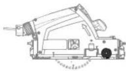
5 Parts of the device
5.1 Main unit
[1-1] Adjustable jaws
[1-2] Speed control
[1-3] KickbackStop function OFF button
[1-4] KickbackStop function status LED
[1-5] Handles
[1-6] Lever for changing the tool
[1-7] Safety lock
[1-8] On/off switch
[1-9] Extractor connector
[1-10] Rotary knobs for adjusting the angle
[1-11] Cable routing
[1-12] Mains power cable
[1-13] Start/end position of saw blades (both sides)
[1-14] Lever for adjusting the scoring unit only
[1-15] Split scale for the cutting depth stop (with/without a guide rail)
[1-16] Cutting depth adjusting screw for re-conditioned saw blades
[1-17] Cutting depth stop
[1-18] Angle scale
[1-19] Gauge marker
[1-20] Viewing window/chip guard
[1-21] Feeler wedge
[1-22] Protective lid
5.2 Scoring unit
[1-23] Button for the scoring unit spindle stop
[1-24] Adjusting wheel for cutting width/cutting depth of scoring unit
[1-25] Adjusting wheel for lateral offset of the scoring unit
[1-26] Lever for activating/deactivating the scoring unit
The illustrations specified are located at the beginning and end of the operating instructions.
Accessories shown or described are not always included in the scope of delivery.
6 Commissioning
WARNING
Unauthorised voltage or frequency.
Risk of accidents
- The mains voltage and the frequency of the power source must correspond to the specifications on the name plate.
▶ In North America, only Festool machines with the voltage specifications 120 V / 60 Hz may be used.

Always switch off the machine before connecting and disconnecting the mains power cable.
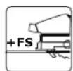
Only use guide rails with a splinter guard that has been cut into using this machine (see section 12.2).
The scoring unit is not aligned with the main saw blade when delivered. Adjust the scoring unit before using it for the first time (see section 8, in the order 8.4/8.5).
6.1 Machines with plug-it connection
Applies to TSV 60 KEBQ.

CAUTION
Heating of the plug it connection if bayonet fitting is not completely locked
Risk of burns
▶ Before switching on the power tool, make sure that the bayonet fitting at the mains cable is closed fully and locked.
Connecting and detaching the mains power cable [1-12] see Fig. [2].
7 Main unit settings
WARNING
Risk of injury, electric shock
▶ Always disconnect the mains plug from the socket before performing any work on the machine.
7.1 Electronics
Speed control
You can continuously adjust the speed within the speed range using the adjusting wheel [1-2] (see "Technical data"). This enables you to optimise the cutting speed to suit each surface.
Speed range per material
| Solid wood (hard, soft) 6 | |
| Chipboard and hardboard 3-6 | |
| Laminated wood, blockboard, veneered and laminated panels | 6 |
| Laminate, mineral materials 4-6 | |
| Plaster- and cement-bonded chipboard and fibreboard | 1-3 |
| Aluminium panels and profiles up to 15 mm | 4-6 |
| Plastics, fibre-reinforced plastics, paper and fabric | 3-5 |
| Acrylic glass 4-5 | |
Overload protection
Electronic overload protection protects the motor from damage if there is an extreme overload. In this case, the motor remains at a standstill and only starts up again once the load has been removed. To restart the machine, you must switch it on again.
Brake
The saw comes with an electronic brake. The saw blade is stopped electronically within approximately two seconds of switching off the machine.
WARNING! The scoring unit does not have an electronic brake and continues to run for approx. 2 seconds after the saw has been switched off.
Temperature cut-out
The power supply is restricted and the speed reduced if the motor exceeds a certain temperature. The power tool continues operating at re-
duced power to allow the ventilator to cool the motor quickly. The power tool starts up again automatically once the motor has cooled sufficiently.
7.2 Adjusting the cutting depth
The cutting depth can be set at 0–62 mm at the cutting depth stop [3-1].
The saw unit can now be pushed downwards as far as the cutting depth that is set.
Cutting depth without guide rail max. 62 mm
Cutting depth with FS guide rail max. 57 mm
7.3 Adjusting the cutting angle
Between 0° and 45°
▶ Open the rotary knobs [4-1].
▶ Swivel the saw unit to the desired cutting angle [4-2].
▶ Close the rotary knobs [4-1].
Both positions ( 0^ and 45^ ) are set at the factory and can be readjusted by the customer service team.

When making angled cuts, slide the viewing window [1-20] to the highest position.
7.4 Selecting the saw blade
Festool saw blades are identified by a coloured ring. The colour of the ring represents the material for which the saw blade is suited.
Refer to the necessary saw blade data (see section 3.2).
| Colour Material Symbol | |
| Yellow Wood | 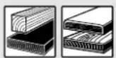 |
| Red Laminate, mineral material |  |
| Green Plaster- and cement-bonded chipboard and fibreboard | 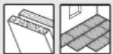 |
| Blue Aluminium, plastic |  |
7.5 Changing the saw blade [5]
![FESTOOL TSV 60 KEBQ - Changing the saw blade [5] - 1](/content/2026/04/627276/images/57c137a2555cc0c7202151f8a74919e88296208573a257fd8bf57547162e5d24.jpg)
WARNING
Risk of injury, electric shock
▶ Always disconnect the mains plug from the socket before performing any work on the machine.

CAUTION
Risk of injury from hot and sharp insertion tool
- Do not use any blunt or faulty insertion tools.
▶ Wear protective gloves when handling an insertion tool.
Removing the saw blade
- Swivel the saw to 0^ before replacing the saw blade and adjust the maximum cutting depth.
▶ Turn the lever [5-3] as far as it will go. Operate the lever only when the saw is at a standstill!
▶ Push the saw unit down until it engages.
▶ Lay the saw on its side on a stable base. Saw blade side upwards.
▶ Loosen the screw [5-5] using the Allen key [5-2].
▶ Remove the saw blade [5-8].
Cleaning the feeler unit
WARNING! Any contamination of the feeler unit may impair the KickbackStop function and therefore prevent the saw blade from being stopped.
▶ Hold the saw unit securely by its handle, close the lever [5-3] and press the saw unit all the way down.
▶ Release the lever [5-3] again and click the saw unit into place.
- Clean the feeler unit [5-9] by blowing it out or using a brush.
Inserting the saw blade
WARNING! Check the screws and flange for contamination and only use clean and undamaged parts.
▶ Hold the saw unit securely by its handle and turn the lever [5-3] as far as it will go.
▶ Push the saw unit down until it engages.
▶ Insert a new saw blade.
WARNING! The direction of rotation of the saw blade [5-7] and saw [5-4] must match. Serious injuries may occur in the event of non-compliance.
English
▶ Insert the outer flange [5-6] in such a way that the pulling peg engages in the recess of the inner flange.
▶ Tighten the screw [5-5].
- Hold the saw unit securely by its handle, close the lever [5-3] and guide the saw unit back upwards.
7.6 Dust extraction

WARNING
Health hazard posed by dust
▶ Always work with an extractor.
▶ Comply with national regulations.
- When sawing carcinogenic materials, always connect a suitable extraction mobile in accordance with national regulations. Do not use the chip collection bag.
Independent extraction
- Secure the connection piece [6-2] of the dust collection bag [6-3] at the extractor connector [6-1] with a clockwise rotation.
▶ To empty, remove the connection piece of the dust collection bag from the extractor connector with an anti-clockwise rotation.
Blockages in the guard may impair safety features. To avoid blockages, it is therefore better to work with a mobile dust extractor at full suction power.
Static charge may occur when sawing (e.g. MDF). If this is the case, work with a mobile dust extractor and an antistatic suction hose.
Festool mobile dust extractor
A Festool mobile dust extractor with a suction hose diameter of 27/32 mm or 36 mm (36 mm recommended due to the reduced risk of clogging) can be connected to the extractor connector [6-1].
The adapter on a 27 diameter suction hose is inserted into the angle adapter [6-4]. The adapter on a 36 diameter suction hose is inserted over the angle adapter [6-4].
CAUTION! A static charge may build up if no antistatic suction hose is used. The user may receive an electric shock and the power tool's electronics may be damaged.
8 Scoring unit settings


WARNING
Risk of injury, electric shock
▶ Always disconnect the mains plug from the socket before performing any work on the machine.
8.1 Scoring unit adjustment procedure
The scoring unit must be aligned with the main saw blade. The work result is influenced by a wide range of limiting conditions. Therefore, check the alignment of the scoring unit before actually cutting with test cuts.
▶ Set the guide play between the saw and guide rails correctly (see section 12.2). This is important for a precise cut.
▶ Set the required cutting depth for the main saw blade (see section 7.2). (Recommendation: The tooth projection should be at least 12 mm if good edge quality is to be achieved on the underside of the workpiece.)
▶ Perform a test cut with the scoring unit activated at a low scoring depth.
▶ Adjust the lateral offset (see section 8.4) until the scoring groove is aligned with the cut of the main saw blade. Check by performing further test cuts.
▶ Adjust the cutting width of the scoring groove on the main saw blade (see section 8.5). Test cuts are also imperative here.
▶ Repeat both of the previous steps until the required cut result is achieved.
Always drive at least 20 - 30 cm into the workpiece with the test cuts. At the start of a rip cut, there may be a larger scoring depth and therefore a wider scoring groove than in the rest of the workpiece.
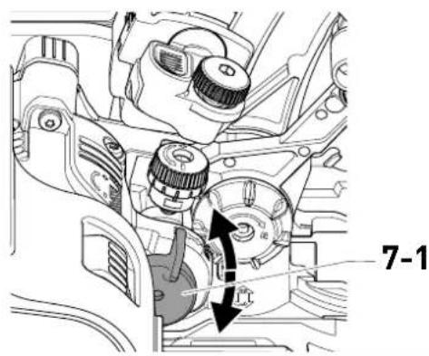
8.2 Activating/deactivating the scoring unit [7]
Activating (ON)
▶ Turn the lever for activating/deactivating [7-1] upwards as far as it will go.
Plunging the main unit also plunges the scoring unit saw blade.
Deactivating (OFF)
▶ Turn the lever for activating/deactivating [7-1] 90° downwards.
The main unit plunges without the scoring unit saw blade.
i The original depth and cutting width settings remain.
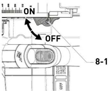
8.3 Activating/deactivating the scoring unit adjustment only [8]
Activating
▶ Turn the lever for adjusting the scoring unit only [8-1] to the right as far as it will go.
The main saw blade is prevented from cutting.
i The main saw blade also rotates when scoring.
Deactivating
▶ Turn the lever for adjusting the scoring unit only [8-1] to the left as far as it will go. The main saw blade saws at the cutting depth set.
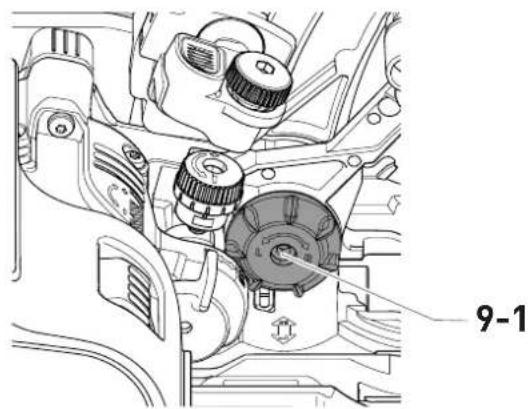
8.4 Setting the lateral offset [9]
![FESTOOL TSV 60 KEBQ - Setting the lateral offset [9] - 1](/content/2026/04/627276/images/823b847cebec84ff8db6ad5ab3e36a3ebe30df87c3487e5ac62e015ba5026f25.jpg)
The cut by the scoring unit blade must be centrally aligned with the cut by the main saw blade.
▶ Set the lateral offset on the adjusting wheel [9-1].
Turning in a clockwise direction (R): The scoring unit moves away from the guide rail.
① One revolution:
- 0.5 mm axial travel
i One catch:
- 0.025 mm axial travel
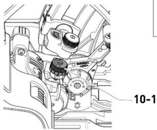
8.5 Adjusting the cutting width (cutting depth) of the scoring unit [10]
![FESTOOL TSV 60 KEBQ - Adjusting the cutting width (cutting depth) of the scoring unit [10] - 1](/content/2026/04/627276/images/48607e2d52245afb16197052707e6b2337de1473505167cdc2f1b114cef5aa93.jpg)
The scoring unit saw blade has a conical cutting tooth, which means that the cutting width is controlled through the cutting depth.
▶ Adjust the cutting width [10-1] on the adjusting wheel.
Turning in a clockwise direction (+): The cutting depth and cutting width increase.
(i) One revolution:
- Change to the cutting width: 0.32 mm
- Change to the cutting depth: 1.3 mm
i One catch:
- Change to the cutting width: 0.025 mm
- Change to the cutting depth: 0.1 mm
(i) Recommendation: Only set the cutting width to be slightly wider than the cutting width of the main saw blade.
8.6 Changing the scoring unit saw blade [11]
![FESTOOL TSV 60 KEBQ - Changing the scoring unit saw blade [11] - 1](/content/2026/04/627276/images/4543c0e61d7211a02f7f597de5044410fcb934837402d9e73213bd08e0c70f93.jpg)
WARNING
Risk of injury, electric shock
▶ Always disconnect the mains plug from the socket before performing any work on the machine.

CAUTION
Risk of injury from hot and sharp insertion tool
- Do not use any blunt or faulty insertion tools.
▶ Wear protective gloves when handling an insertion tool.
Removing the scoring unit saw blade
▶ Activate the scoring unit (see section 8.2).
▶ Turn the lever for changing the tool [11-1] as far as it will go.
▶ Lay the saw on its side on a stable base. Saw blade side upwards.
▶ Press and hold the spindle stop [11-2].
Loosen the screw [11-5] using the small Allen key [11-3] (left-hand thread).
▶ Remove the scoring unit saw blade [11-7].
Inserting the scoring unit saw blade
WARNING! Check the screw [11-5] for contamination. Only use clean and undamaged parts.
- Insert the new saw blade. Imprinted side upwards.
WARNING! The direction of rotation of the saw blade [11-6] and saw [11-4] must match. Serious injuries may occur in the event of non-compliance.
▶ Press and hold the spindle stop [11-2]. Insert the screw [11-5] and tighten using the small Allen key [11-3] (left-hand thread).
8.7 Dust extraction on the scoring unit
- When working with the scoring unit, slide the viewing window [1-20] fully down.
Dust generated at the scoring unit is directed to the dust extraction.
9 Working with the electric power tool

When working on the machine, observe all of the safety warnings that are listed at the start as well as the following rules:
Before starting
- Before each use, check whether the drive unit with the saw blade correctly and fully swivels back up into its initial position in the protective housing. Do not use the saw if the upper end position is not secured. Never clamp or secure the swivelling drive unit at a specific cutting depth. This would mean that the saw blade is not protected.
- Check the plunging mechanism prior to use and do not use the machine if it does not work correctly.
- Check that the saw blade is securely in place.
- Before each use of the saw, check that the KickbackStop is functioning properly (see Section 10.5).
- Make sure that the rotary knob [1-10] is tightened before starting work.
- Make sure that extractor hose and mains power cable do not snag the entire saw cut, either on the workpiece, the workpiece support or hazards on the ground.
- To prevent the mains power cable from being damaged by sharp workpiece edges, hang the mains power cable in the cable holder [1-11].
- Position the workpiece so that it is stress-free and level.
During work
- It is imperative to deactivate the scoring unit when using without the guide rail.
When using without the guide rail, there is a danger of the saw moving forwards unexpectedly. The larger cutting depth on the scoring unit causes damage to the workpiece and the motor may become overloaded.
- Position the saw's plate such that it is always completely level during any work.
- When working, always hold the power tool with both hands on the handles [1-5]. This is a prerequisite for precise work and is essential for plunge-cutting. Plunge into the workpiece slowly and evenly.
-
Only guide the power tool towards the workpiece when it is switched on.
-
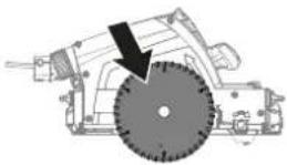
Always push the saw forwards [16-2], and never towards yourself.
- Adapt the infeed speed to prevent the cutters on the saw blade from overheating and prevent plastic materials from melting during cutting. The harder the material to be sawn, the lower the feed speed needs to be.
- Make sure that the guard completely surrounds the saw blade before placing the saw on the worktop or on the ground.
9.1 Acoustic warning signals
Acoustic warning signals sound if the following operating states arise:
Signal Cause Action
| Beeps once. Machine | Reduce the load on the machine. | |
| overloaded | ||
| Beeps continuously. | Scoring unit faulty | Deactivate the scoring unit. Contact a Festool service workshop or specialist dealer. |
9.2 Switch on/off
Pressing the switch-on lock unlocks the plunging mechanism.
▶ Slide the switch-on lock [1-7] upwards and press the on/off switch [1-9] (press = ON / release = OFF).
The saw unit can then be moved downwards. This causes the saw blade to emerge from the protective cover.
9.3 Sawing along the scribe mark
The gauge marker [12-2] displays the cutting line for 0° and 45° cuts (without a guide rail).
9.4 Cutting sections
Position the machine with the front part of the saw table on the workpiece, switch on the machine, push it down to the set cutting depth and push it forward in the cutting direction.
9.5 Sawing cut-outs (plunge cuts)

In order to avoid kickbacks, the following instructions must always be followed when plunge cutting:
- Always position the machine with the rear edge of the saw table against a fixed stop.
- When working with the guide rail, position the machine at the FS-RSP kickback stop (accessory) [16-4], which is clamped to the guide rail.
Procedure
▶ Place the machine on the workpiece and position it at a stop (KickbackStop).
▶ Switch on the machine.
- Slowly push the machine down to the set cutting depth and push it forward in the cutting direction.
The marks [12-1] indicate the absolute front and rear cutting points of the saw blade ( 168 mm) when using the saw at maximum cutting depth with the guide rail.
Plunge cuts with scoring unit
In some cases, it may be necessary to work initially with the scoring unit only (see section 8.3) and carry out the through cutting with the main saw blade in a second procedure. Deactivate the scoring unit when through cutting with the main saw blade (see section 8.2).
9.6 Saws with a scoring unit
The scoring unit cuts the surface of the workpiece slightly wider than the main saw blade. This means that the main saw blade no longer comes into contact with the surface, preventing splinters.

WARNING
Risk of injury
Sawing with the scoring unit creates extremely sharp cutting edges on the workpiece. These pose a cutting hazard for fingers, mains power cables, etc.
▶ Do not touch the cutting edge.
▶ Always keep mains power cables away from the cutting edge.

CAUTION
Risk of injury from the rotating scoring unit saw blade
In the event of a fault in the main unit (e.g. overload), the main saw blade may stop while the scoring unit saw blade continues.
▶ Never reach into the area of the saw blades while the saw is connected to the mains.
▶ Fit the guide rail and set the correct play.
▶ Check the alignment of the scoring unit before actually cutting with appropriate test cuts (see section 8.1).
▶ Saw at the recommended feed speed of 2-4 m/min. (For a 1 m cut, this equates to a time of approx. 15-30 seconds).
For maximum precision, do not work with connected guide rails.
10 KickbackStop
10.1 KickbackStop function

WARNING
Risk of injury
The KickbackStop does not guarantee complete protection against a kickback.
▶ Always concentrate on your work and refer to the safety instructions and warnings.
A kickback while working may cause the saw to lift unintentionally.
The feeler wedge [13-1] detects unintentional lifting (kickback) of the saw from the workpiece or a rail during work and triggers the quick-acting braking of the saw blade (Fig. 13A).
This reduces the risk of a kickback. However, it cannot be entirely ruled out.
KickbackStop function status LED
Colour Meaning
| Green The KickbackStop function is active. | |
| Orange The KickbackStop function is deactivated. | |
| Flashing orange | The KickbackStop function is not active.The saw was started up before the feeler wedge was pressed against the workpiece or a guide rail. The saw's plate is not positioned such that it is completely level.Once the saw has been positioned such that is completely level, the LED will switch to green. If this is not the case, check the Kickback-Stop function (see Section 10.5) |
| Flashing red | The KickbackStop function has been triggered. |
10.2 Unintentional triggering of the KickbackStop function
Working without a guide rail on an uneven workpiece may cause the KickbackStop function to trigger unintentionally (Fig. 13B).
The feeler wedge [13-1] runs along the workpiece. If there is a recess in the workpiece, the position of the feeler wedge will correspond to the position when the workpiece or guide rail is
lifted. This triggers the KickbackStop function. It may then be necessary to work without the KickbackStop function (see Section 10.4).
10.3 Procedure after the KickbackStop function has been triggered
Triggered by unintentional lifting (kickback)
▶ Determine and eliminate any reasons for lifting.
▶ Check the machine for any damage.
▶ Check the feeler wedge for any damage.
▶ Check the KickbackStop function (see Section 10.5).
After the KickbackStop function has unintentionally been triggered
▶ Release the on/off switch and wait until the KickbackStop function status LED is no longer flashing.
▶ Check whether there was an unintentional triggering of the KickbackStop function (see Section 10.2) or a kickback.
▶ Try first to continue working with an active KickbackStop function. Only deactivate the KickbackStop function if you are working without a rail and your workpiece is so uneven that the KickbackStop function would unintentionally be triggered several times (see Section 10.4).
10.4 Working without the KickbackStop function

WARNING
Risk of injury
If the KickbackStop function is deactivated, the saw blade is not stopped when it unintentionally lifts.
▶ Only deactivate the KickbackStop function if you are working without a rail and your workpiece is so uneven that the Kickback-Stop function would unintentionally be triggered several times.
Deactivate the KickbackStop function
▶ Press the KickbackStop function OFF button.
▶ Press and hold the on/off switch within ten seconds.
The KickbackStop function remains deactivated until the on/off switch is next released.
The KickbackStop function can only be deactivated before the saw is switched on.
10.5 Checking the KickbackStop function

WARNING
Risk of injury from a protruding saw blade.
- Carry out function testing on the guide rail.
▶ Before the function testing: - Remove the saw blade,
- Deactivate the scoring unit,
- Set the cutting depth to 0 mm (FS).
▶ Set the cutting depth to 0 mm (FS).
▶ Place the machine on the guide rail.
▶ Switch on the machine.
▶ Press the KickbackStop function OFF button four times at intervals of at least 0.5 seconds within five seconds.
The KickbackStop function status LED flashes alternately red and green.
▶ Within 15 seconds
▷ Press the saw unit down.
▶ Lift the machine at the rear and lower it again.
A signal sounds, the status LED lights up green. The KickbackStop function operates fault-free. If no signal sounds and the status LED does not switch to green, the KickbackStop function is not operating fault-free.
▶ Check whether the function testing was carried out correctly.
- Clean the feeler unit behind the saw blade (see "Changing the saw blade").
If the function testing remains unsuccessful, the machine must no longer be used. Contact your Festool service workshop.
11 Service and maintenance


WARNING
Risk of injury, electric shock
▶ Always pull the mains plug from the socket before performing any servicing and maintenance work.
▶ All maintenance and repair work which requires the housing to be opened should always be carried out by an authorised service workshop.

Customer service and repairs must only be carried out by the manufacturer or service workshops. Find the nearest address at:
www.festool.co.uk/service
Always use original Festool spare parts. Order no. at: www.festool.co.uk/service
Observe the following instructions:
- Damaged safety devices and parts, such as a faulty lever for changing tools [1-6], must be properly repaired or replaced in a recognised specialist workshop, unless otherwise indicated in the operating manual.
▶ Check the condition and fault-free functioning of the recuperating springs, which push the entire drive mechanism bearing into the upper protected end positions.
▶ To ensure constant air circulation, always keep the cooling air openings in the housing clean and free of blockages.
▶ Use an extractor on all openings in order to remove wood chips and splinters from the power tool. Never open the protective lid [1-22]. - When working with plaster- and cement-bonded fibreboards, clean the tool particularly thoroughly. Clean the vents of the power tool and on/off switch using dry, oil-free compressed air. Otherwise, gypsum dust deposits may build up inside the power tool's housing and on the on/off switch and harden when exposed to humidity. This may impair the switching mechanism.
11.1 Reconditioned saw blades
You can use the adjusting screw [14-1] to precisely set the cutting depth for reconditioned saw blades.
▶ Set the cutting depth stop [14-2] to 0 mm (with guide rail).
▶ Unlock the saw unit and push it downwards as far as the stop.
- Screw the adjusting screw [14-1] in until the saw blade comes into contact with the workpiece.
The scoring unit saw blade cannot be re-sharpened because it contains a diamond tooth.
11.2 Saw table wobbles
(i) The saw table must be on an even surface when adjusting the cutting angle.
▶ If the saw table wobbles, the setting must be implemented again.
11.3 Aligning the angle scale
See figure 15.
12 Accessories
Always use accessories and consumable materials approved by Festool. See Festool www.festool.co.uk.
The power tool may become unsafe and lead to serious accidents if other accessories and consumables are used.
In addition to the accessories described, Festool also provides a comprehensive range of system accessories that allow you to use your machine more effectively and in diverse applications, e.g.:
- Set-back stop FS-RSP
- Angle stop FS-WA and FS-WA/90°
- Mobile saw table and work bench STM 1800
- Multifunction table MFT 3
12.1 Saw blades, other accessories
In order to saw different materials quickly and cleanly, Festool offers saw blades for all applications and these are specially designed for your Festool saw.
12.2 Guide system
The guide rail enables you to make clean, accurate cuts while simultaneously protecting the surface of the workpiece from damage. In conjunction with the extensive range of accessories, exact angled cuts, mitre cuts and fitting work can be completed with the guide system. The option of attaching the guide rail securely using clamps [16-5] ensures safer working conditions.
- Adjust the guide play between the saw table and the guide rail using the two adjustable jaws [16-1].
Bed in the splinter guard [16-3] before using the guide rail for the first time:
▶ Set the machine speed to 6.
- Place the machine at the rear end of the guide rail together with the complete guide plate.
▶ Switch on the machine.
- Push down the machine slowly to the max. preset cutting depth and cut along the full length of the splinter guard without stopping.
The edge of the splinter guard now corresponds exactly to the cutting edge.
(i) Position the guide rail for sawing the splinter guard on a test piece of wood.
English
The TSV 60 cuts into the splinter guard further out than a different Festool circular saw. Therefore, always cut into the splinter guard using the saw with which the guide rail is to be used.
Splinter guard with scoring unit
When sawing with a scoring unit, the splinter guard functions only as a gauge marker. Sawing without a splinter guard is not permitted, as this will mean that the guide rail does not sit properly, leading to poor work results.
12.3 Cross cutting guide rail
The cross cutting guide rail is designed for sawing wood and panel materials.
It enables precise and clean cuts, in particular angled cuts can be performed simply and with repeat accuracy. The saw automatically moves back to the initial position after the sawing process.
Observe the instructions in the operating manual for the FSK cross cutting guide rail
13 Environment

Do not dispose of the device in the household waste! Recycle devices, accessories and packaging. Observe applicable national regulations.
In accordance with the European Directive on waste electrical and electronic equipment and implementation in national law, used power tools must be collected separately and handed in for environmentally friendly recycling.
Information on collection points for proper disposal can be found at www.festool.co.uk/recycling.
Information on REACH: www.festool.co.uk/reach
14 General information
Imported into the UK by
Festool UK Ltd
1 Anglo Saxon Way
Bury St Edmunds
IP30 9XH
Great Britain
14.1 Information on data privacy
The power tool contains a chip which automatically stores machine and operating data. The data saved cannot be traced back directly to an individual.
The data can be read in a contactless manner using special devices and shall only be used by
Festool for fault diagnosis, repair and warranty processing and for quality improvement or enhancement of the power tool. The data shall not be used in any other way without the express consent of the customer.
Sommaire
2.5 Aluminiumbearbetning
8.4 Stille inn sideveis justering [9]
![FESTOOL TSV 60 KEBQ - Stille inn sideveis justering [9] - 1](/content/2026/04/627276/images/fc2cfc0624992e4843ea5c3602df5511d991a404c45994fcc1761319ad4c99b0.jpg)
Kolor Material Symbol
natural_image
Technical line drawing of a mechanical assembly with no visible text or symbols![FESTOOL TSV 60 KEBQ - Stille inn sideveis justering [9] - 2](/content/2026/04/627276/images/5e82c55e4c3c206d3aa3f88f7542fc1e9934171148a91a3b0ab39c2e42fe4923.jpg)
![FESTOOL TSV 60 KEBQ - Stille inn sideveis justering [9] - 3](/content/2026/04/627276/images/43a3d98a740927b6ff1e694aa6a24e3e7e29f5864a8064154a96684aa58e871c.jpg)
text_image
11-3 11-5 11-6 11-4 11-7 11-3 11-212
![FESTOOL TSV 60 KEBQ - Stille inn sideveis justering [9] - 4](/content/2026/04/627276/images/624de0cb462a010e320b58bc1e490a022c69ef12709030af52becc4004f77029.jpg)
text_image
12-1 12-2![FESTOOL TSV 60 KEBQ - Stille inn sideveis justering [9] - 5](/content/2026/04/627276/images/3cb9ec99a051090309afad5e6a2a978b18d97a126f59a8da2bc733496b9b55fc.jpg)
16
![FESTOOL TSV 60 KEBQ - Stille inn sideveis justering [9] - 6](/content/2026/04/627276/images/016ec4051177019b996c348eb0d72f29e900f1f4e5894f16079fb49e32ca4dcd.jpg)
text_image
16-2 16-1 16-3 16-4 16-5https://Festool.com/QuickGuide-TSV60K
![FESTOOL TSV 60 KEBQ - Stille inn sideveis justering [9] - 7](/content/2026/04/627276/images/c927538fd4f59186ea293bfec21543ae87e90af318cad6bd5948661a756dee93.jpg)