
HKC 55 KEB - Saw FESTOOL - Free user manual and instructions
Find the device manual for free HKC 55 KEB FESTOOL in PDF.

User questions about HKC 55 KEB FESTOOL
0 question about this device. Answer the ones you know or ask your own.
Ask a new question about this device
Download the instructions for your Saw in PDF format for free! Find your manual HKC 55 KEB - FESTOOL and take your electronic device back in hand. On this page are published all the documents necessary for the use of your device. HKC 55 KEB by FESTOOL.
USER MANUAL HKC 55 KEB FESTOOL
natural_image
Festool CNC cutting tool with green and black components (no visible text or symbols)

| de Originalbetriebsanleitung 10 | |
| en Original instructions 18 | |
| fr Notice d’utilisation d’origine 25 | |
| es Manual de instrucciones original 33 | |
| bg Оригинална инструкция за експлоатация 41 | |
| cs Původní návod k obsluze 50 | |
| da Original brugsanvisning 57 | |
| el ПрWTÓTUNO OBNYIÖV XPNÖNÇ 64 | |
| et Originaalkasutusjuhend 73 | |
| fi Alkuperäiset käyttöohjeet 80 | |
| hr Originalne upute za uporabu 87 | |
| hu Eredeti használati utasítás | 94 |
| it Istruzioni d’esercizio originali | 102 |
| lt | Originali naudojimo instrukcija | 110 |
| lv | Originālā lietošanas pamācība | 118 |
| nb | Original bruksanvisning | 125 |
| nl | Originele gebruiksaanwijzing | 133 |
| pl | Oryginalna instrukcja obstugi | 141 |
| pt | Manual de instruções original | 149 |
| ro | Manualul de utilizare original | 157 |
| sk | Originálny návod na obsluhu | 165 |
| sl | Originalna navodila za uporabo | 172 |
| sv | Originalbruksanvisning | 179 |
1
2A
2B
3
4
5

6
1
2
7
8
en: EU Declaration of ConformityWe declare under sole responsibility that this product complies with all the relevant requirements in the following EU Directives, and following standards or normative documents were applied:
We as the manufacturer declare under our sole responsibility that the product(s) fulfill(s) all the relevant provisions of the following UK Regulations and are manufactured in accordance with the following designated standards:
S.I. 2008/1597 Supply of Machinery [Safety] Regulations 2008
S.I. 2016/1091 Electromagnetic Compatibility Regulations 2016
S.I. 2017/1206 Radio Equipment Regulations 2017
S.I. 2012/3032 Restriction of the Use of Certain Hazardous Substances in Electrical and Electronic Equipment Regulations 2012
BS EN 62841-1:2015 + AC:2015 + A11:2022, BS EN IEC 62841-2-5:2014, BS EN IEC 55014-1:2017 + A11:2020, BS EN IEC 55014-2:1997 + A1:2001 + A2:2008 + AC:1997, BS EN 300 328 V2.2.2, BS EN 303 446-1 V1.2.1, BS EN 301 489-1 V2.2.3, BS EN 301 489-17 V3.2.4, BS EN IEC 63000:2018
Head of Research & Development Products

Tim Weber
Head of Product Compliance
Deutsch
Inhaltsverzeichnis
1 Symbols....18
2 Safety warnings....18
3 Intended use....21
4 Technical data.... 21
5 Parts of the device....21
6 Battery pack.... 21
7 Settings....21
8 Working with the electric power tool....23
9 Service and maintenance....24
10 Accessories....24
11 Environment....24
12 General information....25
1 Symbols

Warning of general danger

Warning of electric shock

Read the operating manual and safety warnings.

Wear ear protection.

Wear protective gloves when changing tools.

Inserting the battery pack.

Remove the battery pack.

Danger area! Keep hands away!

Direction of rotation of saw and the saw blade

Electro-dynamic run-down brake

KickbackStop function

Do not dispose of it with domestic waste.

Tool contains a chip which stores data. See section 12.1

CE conformity marking

UKCA marking: Confirms the conformity of the product with UK regulations.

Tip or advice
2 Safety warnings
2.1 General power tool safety warnings

WARNING! Read all safety warnings, instructions, illustrations and specifications provided with this power tool. Failure to follow all instructions listed below may result in electric shock, fire and/or serious injury.
Save all warnings and instructions for future reference. Follow the operating manual for the charger and the battery pack.
2.2 Safety instructions for specific circular saws
Cutting procedures

- DANGER: Keep hands away from cutting area and the blade. Keep your second hand on auxiliary handle, or motor housing. If both hands are holding the saw, they cannot be cut by the blade.
- Do not reach underneath the workpiece. The guard cannot protect you from the blade below the workpiece.
- Adjust the cutting depth to the thickness of the workpiece. Less than a full tooth of the blade teeth should be visible below the workpiece.
- Never hold the workpiece in your hands or across your leg while cutting. Secure the workpiece to a stable platform. It is important to support the work properly to minimise body exposure, blade binding, or loss of control.
- Hold the power tool by insulated gripping surfaces, when performing an operation where the cutting tool may contact hidden wiring. Contact with a "live" wire will also make exposed metal parts of the power tool "live" and could give the operator an electric shock.
- When ripping, always use a rip fence or straight edge guide. This improves the accuracy of cut and reduces the chance of blade binding.
- Always use blades with correct size and shape (diamond versus round) of arbour holes. Blades that do not match the mounting hardware of the saw will run off-centre, causing loss of control.
- Never use damaged or incorrect blade washers or bolt. The blade washers and bolt were specially designed for your saw, for optimum performance and safety of operation.
Causes of kickbacks and corresponding safety instructions
- kickback is a sudden reaction to a pinched, jammed or misaligned saw blade, causing an uncontrolled saw to lift up and out of the workpiece toward the operator;
- when the blade is pinched or jammed tightly by the kerf closing down, the blade stalls and the motor reaction drives the unit rapidly back toward the operator;
- if the blade becomes twisted or misaligned in the cut, the teeth at the back edge of the blade can dig into the top surface of the wood causing the blade to
climb out of the kerf and jump back toward the operator.
Kickback is the result of saw misuse and/or incorrect operating procedures or conditions and can be avoided by taking proper precautions as given below.
- Maintain a firm grip with both hands on the saw and position your arms to resist kickback forces. Position your body to either side of the blade, but not in line with the blade. Kickback could cause the saw to jump backwards, but kickback forces can be controlled by the operator, if proper precautions are taken.
- When blade is binding, or when interrupting a cut for any reason, release the trigger and hold the saw motionless in the material until the blade comes to a complete stop. Never attempt to remove the saw from the work or pull the saw backward while the blade is in motion or kickback may occur. Investigate and take corrective actions to eliminate the cause of blade binding.
- When restarting a saw in the workpiece, centre the saw blade in the kerf so that the saw teeth are not engaged into the material. If a saw blade binds, it may walk up or kickback from the workpiece as the saw is restarted.
- Support large panels to minimise the risk of blade pinching and kickback. Large panels tend to sag under their own weight. Supports must be placed under the panel on both sides, near the line of cut and near the edge of the panel.
- Do not use dull or damaged blades. Unsharpened or improperly set blades produce narrow kerf causing excessive friction, blade binding and kickback.
- Blade depth and bevel adjusting locking levers must be tight and secure before making the cut. If blade adjustment shifts while cutting, it may cause binding and kickback.
- Use extra caution when sawing into existing walls or other blind areas. The protruding blade may cut objects that can cause kickback.
Lower guard function
- Check the lower guard for proper closing before each use. Do not operate the saw if the lower guard does not move freely and close instantly. Never clamp or tie the lower guard into the open position. If the saw is accidentally dropped, the lower guard may be bent. Raise the lower guard with the retracting handle and make sure it moves freely and does not touch the blade or any other part, in all angles and depths of cut.
- Check the operation of the lower guard spring. If the guard and the spring are not operating properly, they must be serviced before use. Lower guard may operate sluggishly due to damaged parts, gummy deposits, or a build-up of debris.
- The lower guard may be retracted manually only for special cuts such as "plunge cuts" and "compound cuts". Raise the lower guard by the retracting handle and as soon as the blade enters the material, the lower guard must be released. For all other sawing, the lower guard should operate automatically.
- Always observe that the lower guard is covering the blade before placing the saw down on bench or floor. An unprotected, coasting blade will cause the saw to walk backwards, cutting whatever is in its path. Be aware of the time it takes for the blade to stop after switch is released.
Function of the guide wedge [1-5]
- Use the correct saw blade for the guide wedge, where possible. The function of the guide wedge is restricted if using saw blades with a thicker blade core. To ensure that the guide wedge functions properly, make sure the blade core of the saw blade is thinner than the guide wedge and that the tooth width is greater than the thickness of the guide wedge. Expect increased risk of kickback when using a thicker saw blade.
- Do not operate the saw if the guide wedge is bent. Even the slightest problem can cause the guard to close more slowly.
Further safety instructions
- Wear suitable personal protective equipment: Ear protection and safety glasses.
- Use suitable breathing protection to protect your health. In enclosed spaces, ensure that there is sufficient ventilation and connect a mobile dust extractor.
- Harmful/toxic dust may be produced during your work (e.g. paint containing lead, certain types of wood or metals). Contact with or inhalation of this dust may pose a risk for the operating personnel or persons in the vicinity. Comply with the safety regulations that apply in your country.
- Do not install the power tool in a work bench. The power tool may become unsafe and cause serious accidents if installed in work benches from other manufacturers or self-manufactured work benches.
- Do not use power supply units to operate cordless power tools. Only use the intended battery packs. Do not use third-party chargers to charge the battery packs. The use of accessories not expressly authorised by the manufacturer can result in electric shocks and/or serious accidents.
- Check whether there are any signs of damage to the housing components, such as cracks or stress whitening. Have any damaged components repaired before using the power tool.
- Use appropriate detection devices to look for any hidden supply lines or consult your local utility company. If the insertion tool makes contact with live cables, it can result in fire and electric shock. Damage to a gas pipe can lead to an explosion. Penetration of a water pipe can result in damage to property.
- Do not use the machine for overhead work.
- Never place your hands into the chip ejector. You may injure yourself on rotating parts.
- Wait until the power tool has come to a complete halt before placing it down. The insertion tool can get caught and lead to a loss of control of the power tool.
Safety instructions for the pre-assembled saw blade Usage
- The maximum speed specified on the saw blade must not be exceeded and the speed range must be adhered to.
- The pre-installed saw blade is only designed for use in circular saws.
- Proceed with extreme care when unpacking, packing and handling the tool (e.g. installing it in the machine). There is a risk of injury from extremely sharp cutting edges!
- When handling the tool, wearing safety gloves provides a more secure hold of the tool and further reduces the risk of injury.
- Circular saw blades with cracked bodies must be replaced. Repair is not permitted.
- Circular saw blades with a combination design (soldered saw teeth) with saw tooth thickness smaller than 1 mm must no longer be used.
- WARNING! Do not use tools with visible cracks or blunt or damaged cutting edges.
Installation and mounting
- Tools must be clamped in such a way that they cannot come loose during operation.
- When assembling the tools, it must be ensured that the clamping takes place on the tool hub or the clamping surface of the tool, and that the cutting edges do not come into contact with other components.
- Do not lengthen the key or tighten by hitting with a hammer.
- The clamping surfaces must be cleaned to remove contamination, grease, oil and water.
- Clamping screws must be tightened according to the manufacturer's instructions.
- Only securely installed rings, e.g. rings that have been pressed in or those that are held in position by an adhesive bond, may be used to adjust the hole diameter of circular saw blades to the spindle diameter of the machine. The use of loose rings is not permitted.
Service and maintenance
- Repairs or resanding work must only be carried out by Festool customer service workshops or experts.
- The tool design must not be changed.
- Deresinify and clean the tool regularly (cleaning agent with pH between 4.5 and 8).
- Blunt edges can be resharpened on the clamping surface to a minimum cutting edge thickness of 1 mm.
- Only transport the tool in suitable packaging – risk of injury!
2.3 Other risks
In spite of compliance with all relevant design regulations, dangers may still present themselves when the machine is operated, e.g.:
- Touching the saw blade in the area around the front opening below the saw table,
- Touching the part of the saw blade that projects from beneath the workpiece when cutting,
- Touching rotating parts from the side: Saw blade, clamping flange, flange screw,
- Machine kickback when it jams in the workpiece,
- Touching live parts when the housing is open and the battery pack is still plugged in,
- Workpiece parts being thrown off,
- Parts of damaged tools being thrown off,
- Noise emissions,
- Dust emissions.
2.4 Aluminium processing
When processing aluminium, the following measures must be taken for safety reasons:
- Wear protective goggles.
- Connect the power tool to a suitable dust extractor with an antistatic suction hose.
- Regularly clean dust deposits from the motor housing on the power tool.
- Use a saw blade suitable for cutting aluminium.
- When sawing panels, they must be lubricated with petroleum, but thin-walled profiles (up to 3 mm) can be sawed without lubrication.
2.5 Emission levels
The levels determined in accordance with EN 62841 are typically:
| Sound pressure level L | _PA = 91 dB(A) |
| Sound power level L | _WA = 99 dB(A) |
| Uncertainty K = 3 dB |


CAUTION
Noise emissions created while working with the power tool may damage your hearing.
▶ Always use ear protection.
Vibration emission level a_h (vector sum for three directions) and uncertainty K measured in accordance with EN 62841:
| Sawing wood | a_h < 2.5 m/s^2 |
| K = 1.5 m/s^2 | |
| Cutting aluminium | a_h < 2.5 m/s^2 |
| K = 1.5 m/s^2 |
The specified emission levels (vibration, noise)
- are used to compare machines.
- They are also used for making preliminary estimates regarding vibration and noise load during operation.
- They represent the primary applications of the power tool.

CAUTION
The emission values may deviate from the specified values. This is dependent on how the tool is used and the type of workpiece being machined.
- Assess the actual load during the entire operating cycle.
▶ Determine suitable safety measures depending on the actual load.
3 Intended use
Cordless circular saw designed for sawing
- wooden materials and wood-based materials,
- plaster- and cement-bonded fibres,
- plastics.
When fitted with the special saw blades for aluminium that are offered by Festool, these power tools can also be used for sawing aluminium.
Materials containing asbestos must NOT be processed.
Do not use cutting or abrasive wheels.
The user is liable for improper or non-intended use.
3.1 Saw blades
Only use saw blades with the following dimensions:
- Saw blades according to EN 847-1
- Saw blade diameter 160 mm
- Cutting width 1.6–1.8 mm
- Locating bore 20 mm
- Standard blade thickness 1.1–1.4 mm
- Suitable for speeds of up to 9500 min ^-1
Festool saw blades comply with EN 847-1.
Only saw materials for which the saw blade in question has been designed.
4 Technical data
Cordless circular saw HKC 55 KEB
| Motor voltage 18 V | --- |
| Speed (no-load) | 5200 min ^-1 |
| Compatible battery packs Festool series BP 18 ≥ 4 Ah | |
| Inclination 0° to 50° | |
| Cutting depth at 0° 0–55 mm | |
| Cutting depth at 50° 38 mm | |
| Saw blade dimensions 160 x 1.6 x 20 mm | |
| Weight excl. battery pack 3.5 kg | |
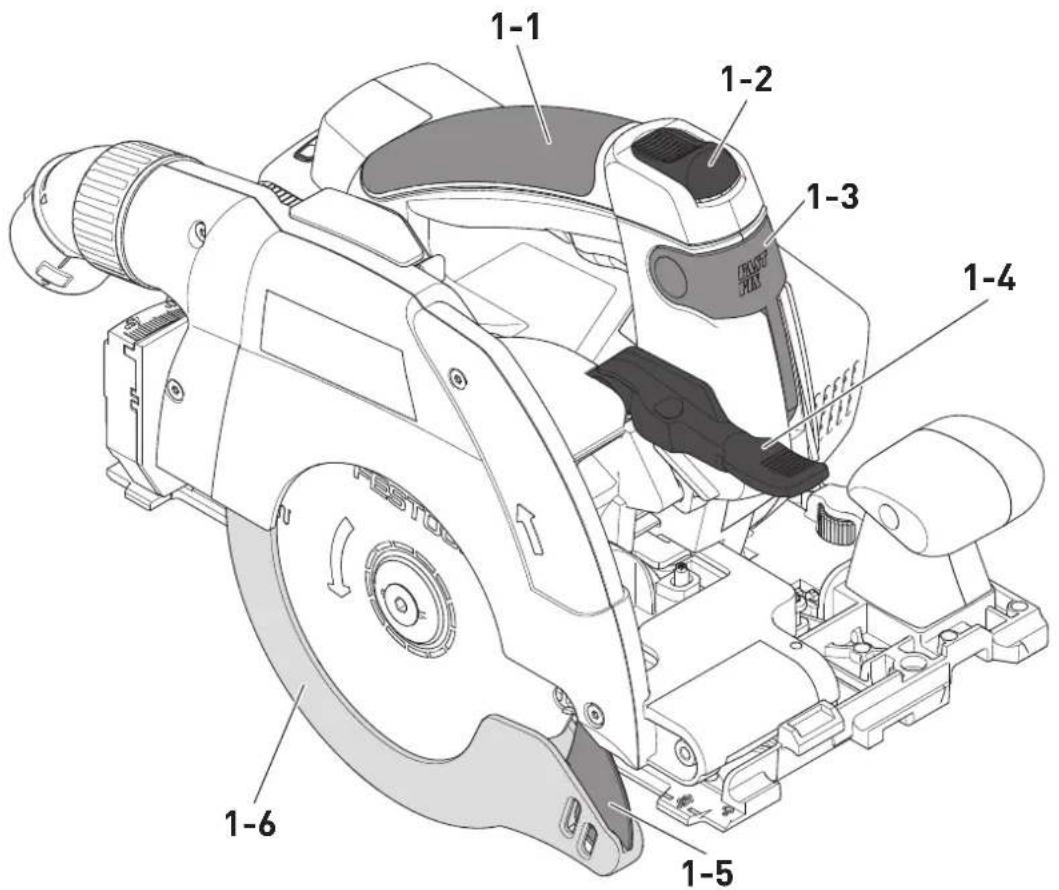
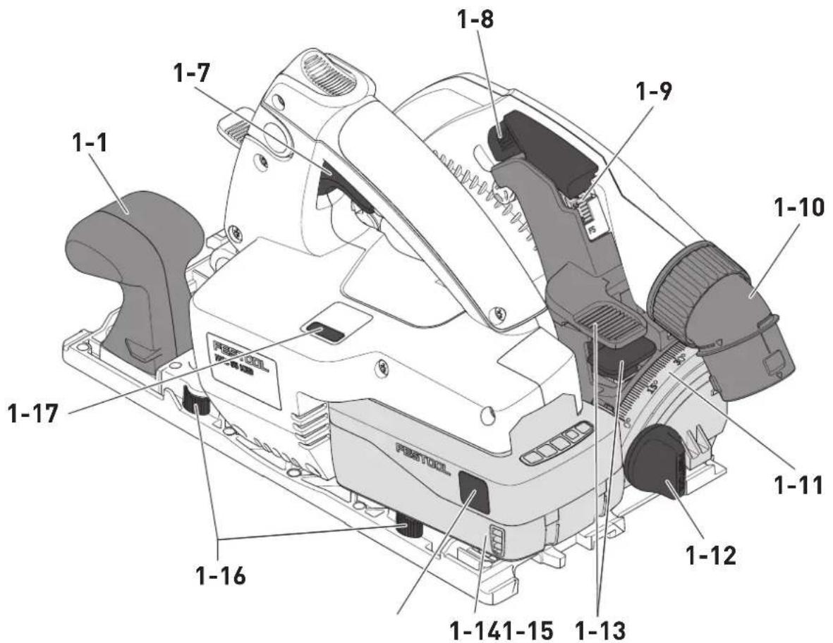
5 Parts of the device
[1-1] Handles
[1-2] Safety lock
[1-3] Lever for changing the tool
[1-4] Retractor lever for pendulum guard
[1-5] Guide wedge
[1-6] Pendulum guard
[1-7] On/off switch
[1-8] Lever for plunge function
[1-9] Split scale for the cutting depth stop (with/without a guide rail)
[1-10] Extractor connector
[1-11] Angle scale
[1-12] Rotary knob for angle setting
[1-13] Cutting depth adjustment
[1-14] Battery pack
[1-15] Button for releasing the battery pack
[1-16] Adjustable jaws
[1-17] Kickback stop function status LED
The specified illustrations appear at the beginning of the Operating Instructions.
Accessories shown or described are not always included in the scope of delivery.
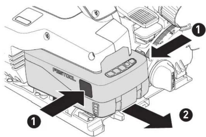
6 Battery pack
Before using the battery pack, check that the battery interface is clean. Any contamination of the battery interface may impair correct contact and lead to the contacts being damaged.
A faulty contact may result in the machine overheating or being damaged.
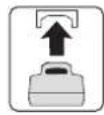
[2A]
Remove the battery pack.
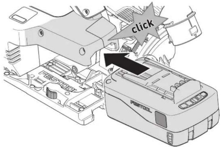
[2B]

Insert the battery pack until it clicks into place.
Further information about the charger and battery pack can be found in the corresponding operating manual.
7 Settings

WARNING
Risk of injury
- Remove the battery pack from the power tool before performing any work on the power tool.
7.1 Electronics
Temperature cut-out
The power supply is restricted and the speed reduced if the motor exceeds a certain temperature. The power tool continues operating at reduced power to allow the ventilator to cool the motor quickly. The power tool starts up again automatically once the motor has cooled sufficiently.
Overload protection
Electronic overload protection protects the motor from damage if there is an extreme overload. In this case, the motor remains at a standstill and only starts up again once the load has been removed. To restart the machine, you must switch it on again.
Restart protection
The built-in restart protection prevents the power tool from starting up again automatically if the power is disconnected when the on/off switch is pressed. In this case, the power tool must be switched off and then switched back on again.
Brake
The saw comes with an electronic brake. The saw blade is stopped electronically within approximately two seconds of switching off the machine.
7.2 Festool app\*
The power tool can be configured with the Festool app. To do this, the battery pack used must be a Bluetooth® battery pack.
The battery pack is connected via Bluetooth®, see the operating manual for the battery pack.
English
You can find further information about operating the power tool in the Festool app.
* Not available in all countries.
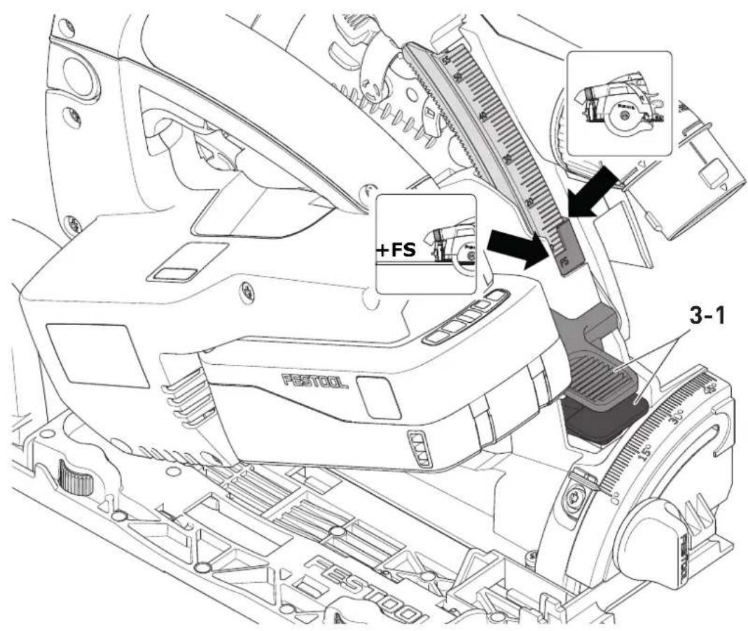
7.3 Adjusting the cutting depth
The cutting depth can be set at 0 - 55 mm.
▶ Press cutting depth adjustment [3-1].
▶ Pull up or push down saw at main handle.

Cutting depth without guide rail/track rail max. 55 mm

Cutting depth with guide rail/track rail max. 51 mm
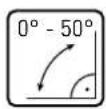
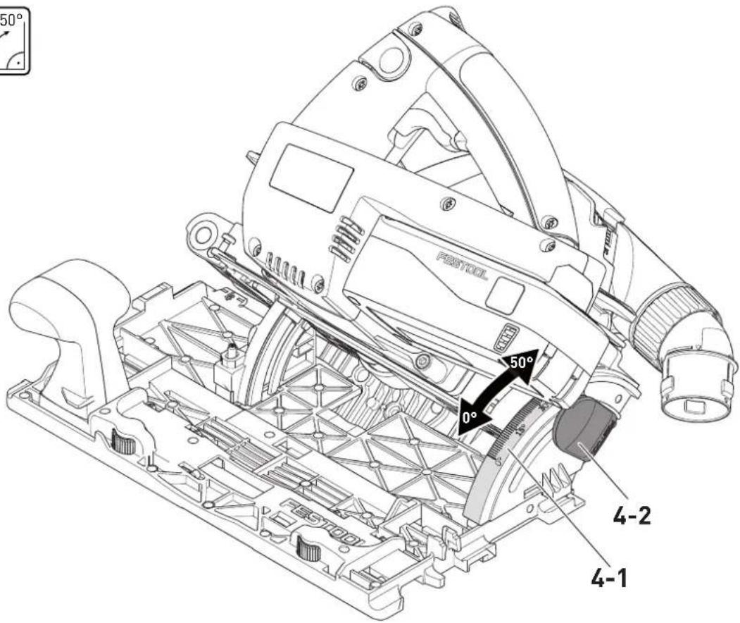
7.4 Adjusting the cutting angle
The saw table must be on an even surface when adjusting the cutting angle.
Between 0° and 50°:
▶ Open the rotary knob [4-2].
- Swivel the saw unit to the required cutting angle [4-1].
▶ Close the rotary knob [4-2].
Both adjustments ( 0^ and 50^ ) are set at the factory and can be readjusted by the customer service team.
For angled cuts, the cutting depth is smaller than the value displayed on the cutting depth scale.
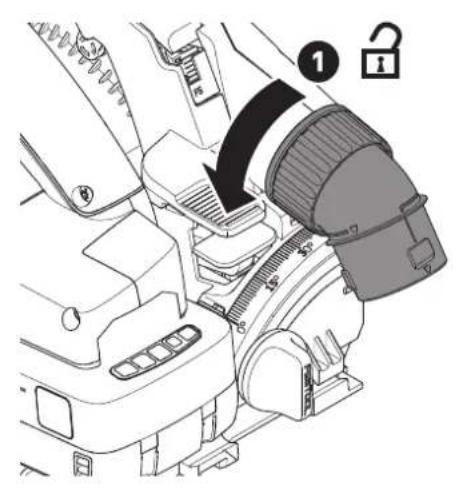
7.5 Adjust pendulum guard

CAUTION
Risk of injury! Sharp edges!
The pendulum guard swings back quickly in the event of sudden release.
- The pendulum guard [1-6] must only be opened with the retractor lever [1-4].
7.6 Selecting the saw blade
Festool saw blades are identified by a coloured ring. The colour of the ring represents the material for which the saw blade is suited.
| Colour Material Symbol | |
| Yellow Wood | 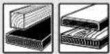 |
| Red Laminate, mineral material |  |
| Green Plaster- and cement-bonded chipboard and fibreboard | 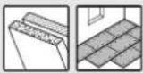 |
| Blue Aluminium, plastic | 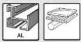 |
7.7 Changing the saw blade

WARNING
Risk of injury
- Remove the battery pack from the power tool before performing any work on the power tool.


CAUTION
Risk of injury from hot and sharp tool.
▶ Do not use any blunt or faulty tools.
▶ Wear protective gloves when handling a tool.
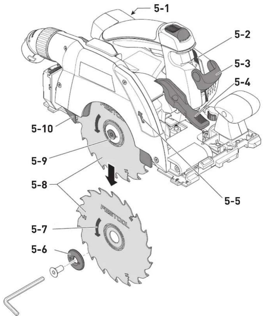
Removing the saw blade
- Swivel saw to 0° position before replacing the saw blade and set maximum cutting depth.
▶ Position saw on motor cover when replacing [5-1].
▶ Turn the lever [5-3] as far as the stop.
▶ Open the screw [5-9] using the Allen key [5-2]. - Hold the pendulum guard open [5-10] only with retractor lever [5-4].
▶ Remove the saw blade [5-8].
Inserting the saw blade
WARNING! Check the screws and flange for contamination and only use clean and undamaged parts.
▶ Insert the new saw blade.
WARNING! The direction of rotation of the saw blade [5-7] and saw [5-5] must match. Serious injuries may occur in the event of non-compliance.
▶ Insert the outer flange [5-6] so that the pin engages in the recess on the inner flange.
▶ Release retractor lever [5-4] and allow the pendulum guard [5-10] to swivel back to its final position.
▶ Tighten the screw [5-9].
▶ Reposition the lever [5-3].
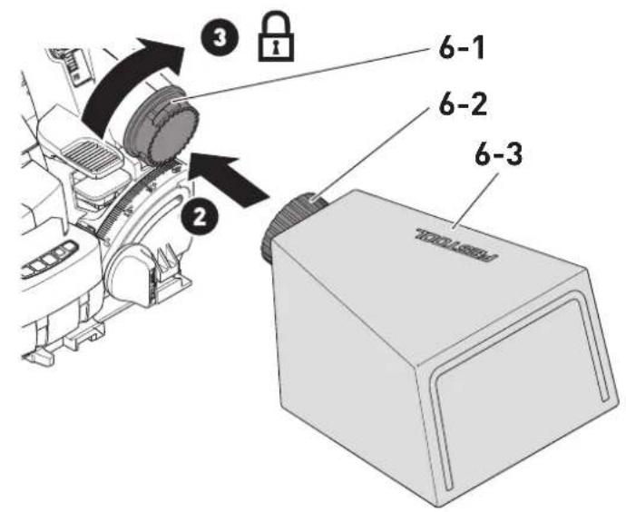
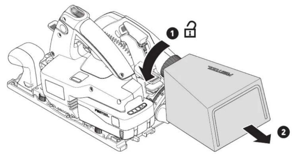
7.8 Dust extraction [6]
![FESTOOL HKC 55 KEB - Dust extraction [6] - 1](/content/2026/04/738357/images/7600267b1ac4a5d9285412632e1c5af9679ab030897f70d8694b508b96e20007.jpg)
WARNING
Health hazard posed by dust
▶ Always work with an extractor.
▶ Comply with national regulations.
- When sawing carcinogenic materials, always connect a suitable extraction mobile in accordance with national regulations. Do not use the chip collection bag.
Independent extraction
- Secure the connection piece [6-2] of the dust collection bag [6-3] at the extractor connector [6-1] with a clockwise rotation.
▶ To empty, remove the connection piece of the dust collection bag from the extractor connector with an anti-clockwise rotation.
Festool mobile dust extractor
A Festool mobile dust extractor with a suction hose diameter of 27/32 mm or 36 mm (36 mm recommended due to the reduced risk of clogging) can be connected to the extractor connector [6-1].
The adapter on a 27 diameter suction hose is inserted into the angle adapter. The adapter on a 36 diameter suction hose is inserted over the angle adapter.
CAUTION! A static charge may build up if no antistatic suction hose is used. The user may receive an electric shock and the power tool's electronics may be damaged.
8 Working with the electric power tool

When working on the machine, observe all of the safety warnings that are listed at the start as well as the following rules:
Before starting
- Before each use, check that the pendulum guard is working correctly using the retractor lever [1-4].
Ensure that the pendulum guard can move freely and does not come into contact with the saw blade or other parts at any cutting angle or depth. Only use this power tool when it is in perfect working order. - Always secure the workpiece in such a way that it cannot move during machining.
- Make sure that the extractor hose does not snag the entire saw cut, either on the workpiece, the workpiece support or hazards on the ground.
- Make sure that the rotary knob [1-12] is tightened before starting work.
- CAUTION! Risk of overheating. Before use, make sure that the battery pack is securely clicked into place.
During work
- When working, always hold the power tool with both hands on the handles [1-1]. This is a prerequisite for precise work and is essential for plunge-cutting. Plunge into the workpiece slowly and evenly.
- Only guide the power tool towards the workpiece when it is switched on.
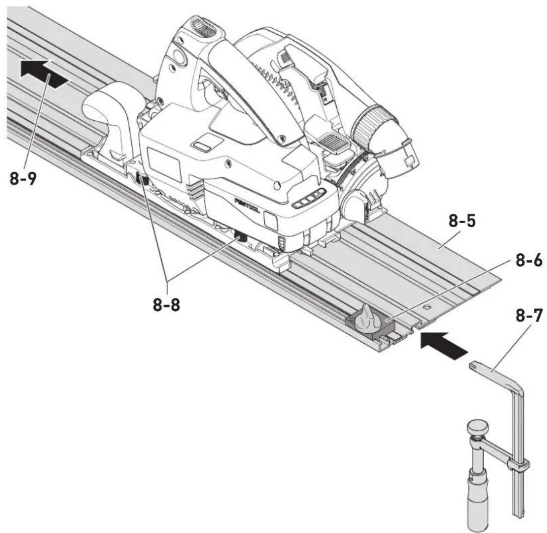
- Always push the saw forwards [8-9], and never towards yourself.
- Adapt the infeed speed to prevent the cutters on the saw blade from overheating and prevent plastic materials from melting during cutting. The harder the material to be sawn, the lower the feed speed needs to be.
8.1 Switch on/off
▶ Slide switch-on lock [1-2] upwards.
▶ Press the ON/OFF switch [1-7].
$$ \text { Press } = 0 \mathrm{N} $$
$$ \text { Release } = 0 \text { FF } $$
8.2 Warning signals
Warning signals occur and the power tool switches off in the following operating states:
| Acoustic signal | Cause Action | |
| Beeps once. | Battery pack empty/ incompatible. | Charge/change the battery pack. |
| Power tool overloaded. | Reduce the load on the power tool. | |
| Power tool has overheated. | Once it has cooled down, restart the power tool. | |
| Beeps continuously. | The power tool is faulty. | Contact the manufacturer to rectify the fault. |
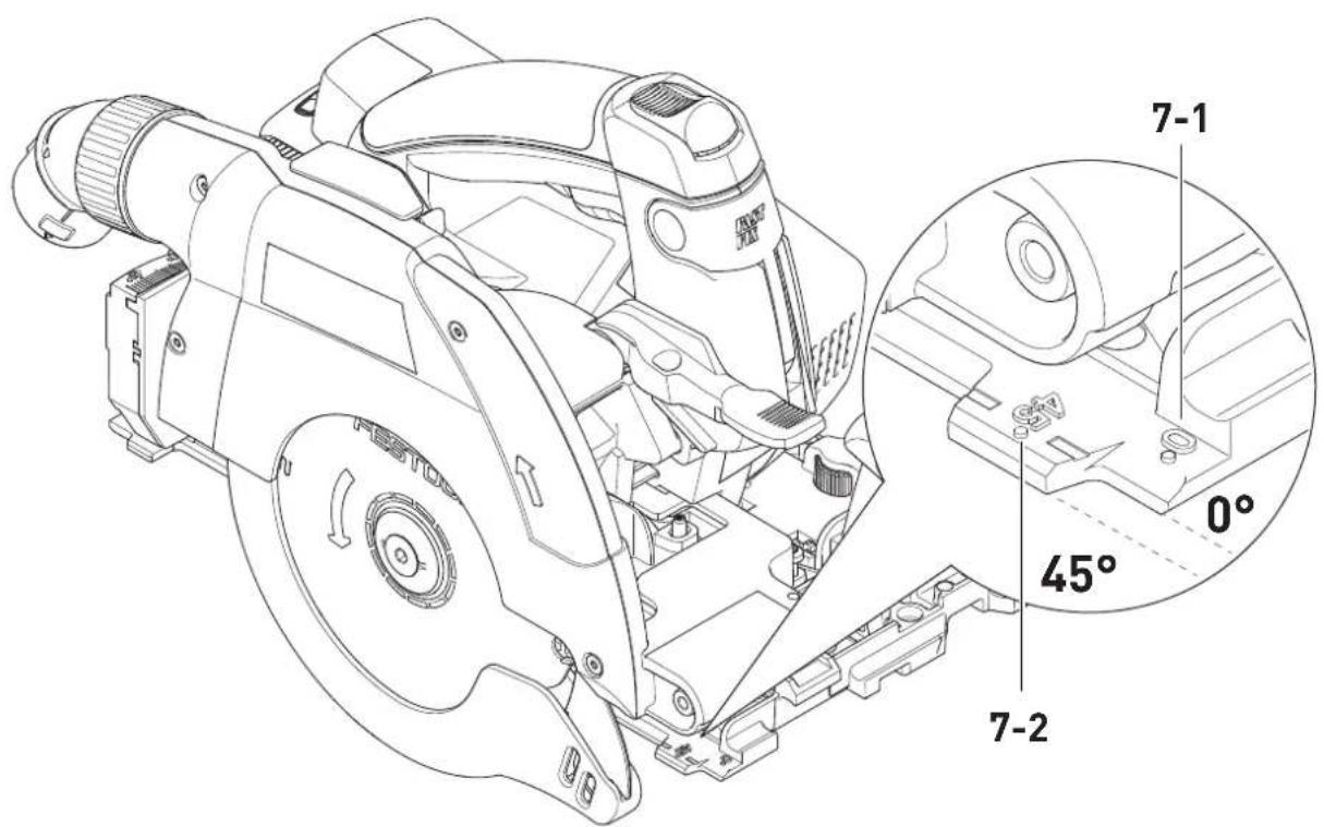
8.3 Sawing along the scribe mark
The cut indicators display the cutting sequence without a guide rail:
0^ cuts: [7-1]
45^ cuts: [7-2]
8.4 Cutting sections
Position the saw with the front part of the saw table on the workpiece, switch on saw and push forward in cutting direction.
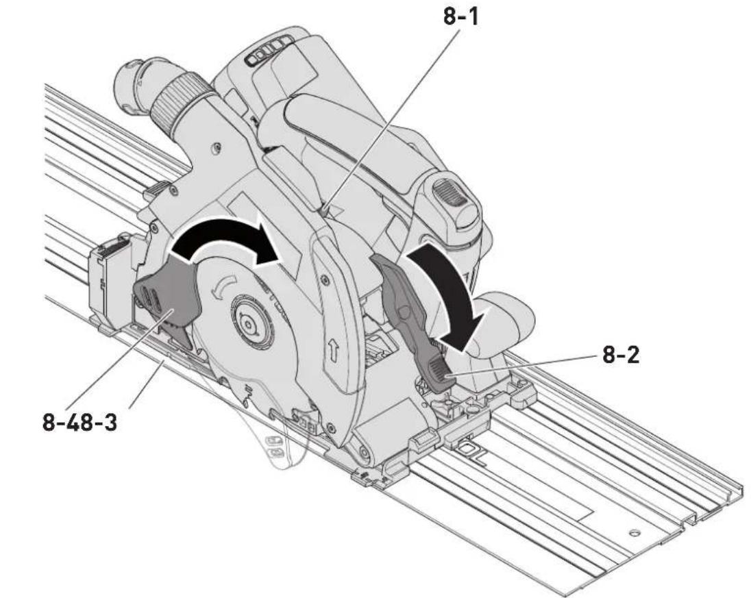
8.5 Sawing cut-outs (plunge cuts)

In order to avoid kickbacks, the following instructions must always be followed when plunge cutting:
- Always position the machine with the rear edge of the saw table against a fixed stop.
- When working with the guide rail, position the machine at the FS-RSP kickback stop (accessory) [8-6], which is clamped to the guide rail.
Procedure
▶ Set cutting depth (see section 7.3).
▶ Press lever [8-1] down.
☑ Sawing unit swivels upwards to plunge-cut position.
▶ Hold retractor lever [8-2] downwards as far as stop.
☑ Pendulum guard [8-4] opens and the saw blade is exposed.
- Position saw on workpiece and position against a stop (kickback stop).
▶ Switch on saw.
- Slowly press down saw to the set cutting depth until the saw engages, release retractor lever [8-2] and push forward in cutting direction [8-9].
☑ The notch [8-3] indicates the absolute rear cutting point of the saw blade (diameter 160 mm) when using the saw at maximum cutting depth with the guide rail.
8.6 Kickback stop function

WARNING
Risk of injury
The KickbackStop does not guarantee complete protection against a kickback.
▶ Always concentrate on your work and refer to the safety instructions and warnings.
English
A kickback while working may cause the saw to lift unintentionally.
The saw detects unintentional lifting (kickback) from the workpiece or a rail during work and triggers the quick-acting braking of the saw blade.
This reduces the risk of a kickback. However, it cannot be entirely ruled out.
Kickback stop function status LED
| Colour Meaning | |
| Green The kickback stop function is active. | |
| Flashing red The kickback stop function has been triggered. | |
| Red, orange or off. | The kickback stop function is faulty. ▶ Remove battery pack. ▶ Contact Customer Service. |
8.7 Procedure after the kickback stop function has been triggered
▶ Release the on/off switch [1-7] and wait until the kickback stop function status LED [1-17] stops flashing.
- Determine and eliminate any reasons for the kickback.
▶ Check the machine for any damage.
9 Service and maintenance
WARNING
Risk of injury, electric shock
▶ Always remove the battery pack from the power tool before performing any maintenance or service work.
▶ Any maintenance and repair work that requires the motor housing to be opened must only be carried out by an authorised service workshop.
Customer service and repairs must only be carried out by the manufacturer or service workshops. You must only use original Festool spare parts.
Further information: www.festool.co.uk/service

Cleaning the machine regularly, especially the adjusting devices and guides, is an important safety factor.
Observe the following instructions:
-
Damaged safety devices and parts, such as a faulty lever for changing tools [1-3], must be properly repaired or replaced in a recognised specialist workshop, unless otherwise indicated in the operating manual.
▶ To ensure constant air circulation, always keep the cooling air openings in the housing clean and free of blockages.
▶ Use an extractor on all openings in order to remove wood chips and splinters from the power tool. Never open the protective lid.
The pendulum guard must always be able to move freely and close independently. Always keep the area around the pendulum guard clean. Clear from dust and chippings by blowing out with compressed air or using a brush. -
Keep the contacts on the power tool, charger and battery pack clean.
- When working with plaster- and cement-bonded fibreboards, clean the tool particularly thoroughly. Clean the vents of the power tool and on/off switch using dry, oil-free compressed air. Otherwise, gypsum dust deposits may build up inside the power tool's housing and on the on/off switch and harden when exposed to humidity. This may impair the switching mechanism.
10 Accessories
Always use accessories and consumables approved by Festool. See www.festool.co.uk.
The power tool may become unsafe and lead to serious accidents if other accessories and consumables are used.
10.1 Saw blades, other accessories
In order to saw different materials quickly and cleanly, Festool offers saw blades for all applications and these are specially designed for your Festool saw.
10.2 Guide rail
The guide rail enables you to make clean, accurate cuts while simultaneously protecting the surface of the workpiece from damage.
In conjunction with the extensive range of accessories, exact angled cuts, mitre cuts and fitting work can be completed with the guide system. The option of attaching the guide rail securely using clamps [8-7] ensures safer working conditions.
▶ Adjust the guide play between the saw table and the guide rail using the two adjustable jaws [8-8].
Bed in the splinter guard before using the guide rail for the first time [8-5]:
- Position saw with the entire guide plate at the rear end of the guide rail.
- Swivel saw to 0° position and set maximum cutting depth.
▶ Switch on saw. - Slowly drop the splinter guard across the entire length without setting down.
☑ The edge of the splinter guard now corresponds exactly to the cutting edge.
i Position the guide rail for sawing the splinter guard on a test piece of wood.
10.3 Cross cutting guide rail
The cross cutting guide rail is designed for sawing wood and panel materials.
It enables precise and clean cuts, in particular angled cuts can be performed simply and with repeat accuracy. The saw automatically moves back to the initial position after the sawing process.
Observe the instructions in the operating manual for the FSK cross cutting guide rail
11 Environment

Do not dispose of electrical devices, used batteries and battery packs in the household waste. Recycle devices, accessories and
packaging. Observe applicable national regulations.
Before disposing of used batteries, battery packs and lamps, separate them from the electrical device without destroying them. This means they can be recycled efficiently.
In accordance with the European Directive on waste electrical and electronic equipment and implementation in national law, used electrical devices must be collected separately and handed in for environmentally friendly recycling.
Information on the collection points can be viewed at www.festool.com/environment.
Information on critical materials: www.festool.co.uk/reach
12 General information
Imported into the UK by
Festool UK Ltd
1 Anglo Saxon Way
Bury St Edmunds
IP30 9XH
Great Britain
12.1 Information on data privacy
The power tool contains a chip which automatically stores machine and operating data. The data saved cannot be traced back directly to an individual.
The data can be read in a contactless manner using special devices and shall only be used by Festool for fault diagnosis, repair and warranty processing and for quality improvement or enhancement of the power tool. The data shall not be used in any other way without the express consent of the customer.
12.2 Bluetooth®
The Bluetooth ^® word mark and the logos are registered trademarks of Bluetooth SIG, Inc.; they are used by TTS Tooltechnic Systems AG & Co. KG, and therefore by Festool, under licence.
12.3 Licence information
Licence information on any open source licences used in the product can be found in the Festool app* at Information > Power tool open source licenses.
* Not available in all countries.
Français
Sommaire
1 Symboles.... 25
12.3 Informations relatives aux licences
Kolor Material Symbol


- Deutsch
- Inhaltsverzeichnis
- Symbols
- Safety warnings
- General power tool safety warnings
- Safety instructions for specific circular saws
- Cutting procedures
- Causes of kickbacks and corresponding safety instructions
- Lower guard function
- Function of the guide wedge [1-5]
- Further safety instructions
- Safety instructions for the pre-assembled saw blade Usage
- Installation and mounting
- Service and maintenance
- Other risks
- Aluminium processing
- Emission levels
- CAUTION
- Noise emissions created while working with the power tool may damage your hearing.
- The emission values may deviate from the specified values. This is dependent on how the tool is used and the type of workpiece being machined.
- Intended use
- Saw blades
- Technical data
- Parts of the device
- Battery pack
- Settings
- WARNING
- Risk of injury
- Electronics
- Temperature cut-out
- Overload protection
- Restart protection
- Brake
- Festool app\*
- English
- Adjusting the cutting depth
- Adjusting the cutting angle
- Between 0° and 50°:
- Adjust pendulum guard
- Risk of injury! Sharp edges!
- The pendulum guard swings back quickly in the event of sudden release.
- Selecting the saw blade
- Changing the saw blade
- Risk of injury from hot and sharp tool.
- Removing the saw blade
- Inserting the saw blade
- Dust extraction [6]
- Health hazard posed by dust
- Independent extraction
- Festool mobile dust extractor
- Working with the electric power tool
- Before starting
- During work
- Switch on/off
- Warning signals
- Sawing along the scribe mark
- Cutting sections
- Sawing cut-outs (plunge cuts)
- Procedure
- Kickback stop function
- The KickbackStop does not guarantee complete protection against a kickback.
- Procedure after the kickback stop function has been triggered
- Service and maintenance
- Risk of injury, electric shock
- Observe the following instructions:
- Accessories
- Saw blades, other accessories
- Guide rail
- Bed in the splinter guard before using the guide rail for the first time [8-5]:
- Cross cutting guide rail
- Observe the instructions in the operating manual for the FSK cross cutting guide rail
- Environment
- General information
- Imported into the UK by
- Information on data privacy
- Bluetooth®
- Licence information
- Français
- Sommaire
- Informations relatives aux licences
Brand : FESTOOL
Model : HKC 55 KEB
Category : Saw