PSC 420 EB-Basic-4 0 - Saw FESTOOL - Free user manual and instructions
Find the device manual for free PSC 420 EB-Basic-4 0 FESTOOL in PDF.

| Product type | Cordless jigsaw |
| Brand | Festool |
| Model | PSC 420 EB-Basic-4 0 |
| Motor voltage | 10.8 - 18 V |
| Cutting speed | 1500 - 3800 rpm (PSBC: 1000 - 3800 rpm) |
| Stroke length | 26 mm |
| Pendulum stroke | 4 levels (0-3) |
| Max. tilt | 45° (with angle table WT-PS 400) |
| Maximum cutting depth (wood) | 120 mm |
| Maximum cutting depth (aluminum) | 20 mm |
| Maximum cutting depth (steel) | 10 mm |
| Weight without battery | 1.8 kg |
| Weight with battery (BP 18 Li 6.2 AS) | 2.5 kg |
| Power supply | Festool BP 18 V lithium-ion battery (not included) |
| Compatible battery type | Festool BP 18 Li (3.1; 5.2; 6.2 Ah) with or without Bluetooth |
| Dust extraction connection | Diameter 27 mm |
| Lighting | Continuous/stroboscopic light (adjustable) |
| Main functions | Adjustable pendulum stroke, variable speed, automatic load detection (position A), anti-splash guard, splinter guard, blade ejection |
| Safety | On/off switch, overload/overtemperature audible signal, stroboscopic light can be disabled |
| Maintenance and cleaning | Regularly clean the chip ejection opening, dust the motor housing, check the guide roller |
| Spare parts and repairability | Saw blades (T-shank), splinter guards, base plates, angle/adaptable table, batteries, chargers. Repair by authorized Festool service center. |
| Included accessories | None (Basic); saw blade, battery and charger sold separately |
| General information | User manual available in PDF. Registered trademark Festool. Made in Germany. |
Frequently Asked Questions - PSC 420 EB-Basic-4 0 FESTOOL
User questions about PSC 420 EB-Basic-4 0 FESTOOL
0 question about this device. Answer the ones you know or ask your own.
Ask a new question about this device
Download the instructions for your Saw in PDF format for free! Find your manual PSC 420 EB-Basic-4 0 - FESTOOL and take your electronic device back in hand. On this page are published all the documents necessary for the use of your device. PSC 420 EB-Basic-4 0 by FESTOOL.
USER MANUAL PSC 420 EB-Basic-4 0 FESTOOL
natural_image
Two Fastbox excavators with black and green branding, displayed on metal bases (no visible text or symbols)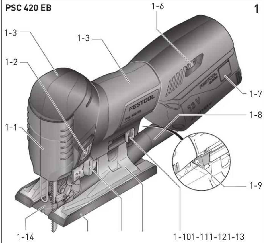


PSC 420 EB 205259,205260
PSBC 420 EB 205263
de EG-Konformitätserklärung. Wir erklären in alleiniger Verantwortung, dass dieses Produkt allen einschlägigen Bestimmungen der folgenden Richtlinien einschließlich ihrer Änderungen entspricht und mit den folgenden Normen übereinstimmt:
en EC-Declaration of Conformity. We declare under our sole responsibility that this product is in conformity with all relevant provisions of the following directives including their amendments and complies with the following standards:
fr CE-Déclaration de conformité communautaire. Nous déclarons sous notre propre responsabilité que ce produit est conforme aux normes ou documents de normalisation suivants:
es CE-Declaración de conformidad. Declaramos bajo nuestra exclusiva responsabilidad que este producto corresponde a las siguientes normas o documentos normalizados:
it CE-Dichiarazione di conformità. Dichiariamo sotto la nostra esclusiva responsabilità che il presente prodotto e conforme alle norme e ai documenti normativi seguenti:
nl EG-conformiteitsverklaring. Wij verklaren op eigen verantwoordelijkheid dat dit produkt voldoet aan de volgende normen of normatieve documenten:
sv EG-konformitetsförklaring. Vi förklarar i eget ansvar, att denna produkt stämmer överens med följande normer och normativa dokument:
fi EY-standardinmukaisuusvakuutus. Va-kuutamme yksinvastuullisina, etta tuote on seuraavien standardien ja normatiivisten ohjeiden mukainen:
da EF-konformitetserklæring. Vi erklærer at have alene ansvaret for, at dette produkt er i overensstemmelse med de følgende normer eller normative dokumenter:
nb CE-Konformitetserklæring. Vi erklærer på eget ansvar at dette produktet er i overensstemmelse med følgende normer eller normative dokumenter:
Markus Stark Head of Product Development

Ralf Brandt Head of Product Conformity
natural_image
Four black circular icons showing different workplace safety symbols: helmet, mask, head with glasses, headset, and hand (no text or labels)1 Symbols....15
2 Safety warnings....15
3 Intended use 16
4 Technical data.... 17
5 Parts of the machine....17
6 Commissioning....17
7 Battery pack.... 17
8 Settings....18
9 Working with the electric power tool.....19
10 Service and maintenance....20
11 Accessories.... 21
12 Environment....22
13 General information....22
1 Symbols

Warning of general danger

Warning of electric shock

Read the operating instructions and safety instructions.

Wear a dust mask.

Wear ear protection.

Wear protective goggles.

Wear protective gloves.

Inserting the battery pack

Removing the battery pack

Do not dispose of it with domestic waste.

CE marking: Confirms the conformity of the power tool with the European Community directives.

Tip or advice

Handling instruction
2 Safety warnings
2.1 General power tool safety warnings

WARNING! Read all safety warnings, instructions, illustrations and specifications provided with this power tool. Failure to follow all instructions listed below may result in electric shock, fire and/or serious injury.
Save all warnings and instructions for future reference.
The term "power tool" in the warnings refers to your mains-operated (corded) power tool or battery-operated (cordless) power tool.
Follow the operating manual for the charger and the battery pack.
2.2 Machine-specific safety notices
- Hold the power tool by insulated gripping surfaces, when performing an operation where the cutting accessory may contact hidden wiring. Cutting accessory contacting a "live" wire may make exposed metal parts of the power tool "live" and could give the operator an electric shock.
- Use clamps or another practical way to secure and support the workpiece to a stable platform. Holding the workpiece by hand or against your body leaves it unstable and may lead to loss of control.
- Festool electric power tools must only be installed on work tables provided by Festool for this purpose. If the tool is installed in another, or self-made, work table, it can become unstable and result in serious accidents.
- Wait until the power tool has come to a complete halt before placing it down. The insertion tool can get caught and lead to a loss of control of the power tool.
- Deformed or cracked saw blades and saw blades with blunt or broken cutting edges must not be used.
- The saw blade on the jigsaw must always be running when it makes contact with the workpiece.
Wear suitable personal protective equipment: Ear protection, protective goggles, dust mask for work that generates dust, protective gloves for working with rough materials and for changing tools. - Harmful/poisonous dust may be produced when working (e.g. paint products con-


taining lead and some types of wood).
Contact with or inhalation of this dust may pose a risk for the operating personnel or persons in the vicinity. Comply with the safety regulations that apply in your country. Connect the power tool to a suitable dust extractor.
- Always connect the machine to a dust extractor when performing work that generates dust.
- Stroboscopic light can cause epileptic seizures. Do not use this machine if you are susceptible to epileptic seizures.
- Do not look into the stroboscope light. Looking into the light source can damage your vision.
- Do not use power supply units or third-party battery packs to operate cordless power tools. Do not use third-party chargers to charge the battery packs. The use of accessories not expressly authorised by the manufacturer can result in electric shocks and/or serious accidents.
- Only for AS/NZS: The tool shall always be supplied via residual current device with a rated residual current of 30 mA or less.
2.3 Metal processing

When processing metal, the following measures must be taken for safety reasons:
- Connect the machine to a suitable dust extractor.
- Regularly remove dust deposits in the motor housing.
- Use a saw blade specifically designed for the cutting of metal.
- Close the chip guard.

Wear protective goggles.
2.4 Emission levels
The levels determined in accordance with EN 62841 are typically:
Sound pressure level L _PA = 88 dB(A)
Sound power level L _WA = 99 dB(A)
Uncertainty K = 5 dB


CAUTION
Noise generated when working Risk of damage to hearing
▶ Use ear protection.
Vibration emission level a_h (vector sum for three directions) and uncertainty K measured in accordance with EN 62841:
PSC 420 EB PSBC 420 EB
| Sawing wood a _h | 7.0 m/s ^2 | 15.0 m/s ^2 |
| Sawing metal a _h | 8.0 m/s ^2 | 7.5 m/s ^2 |
| Uncertainty K | 1.5 m/s ^2 | 1.5 m/s ^2 |
The specified emission levels (vibration, noise)
- are used to compare machines.
- They are also used for making preliminary estimates regarding vibration and noise load during operation.
- They represent the primary applications of the power tool.

CAUTION
The emission values may deviate from the specified values. This is dependent on how the tool is used and the type of workpiece being machined.
▶ The actual load during the entire operating cycle must be evaluated.
▶ Depending on the actual load, suitable protective measures must be defined in order to protect the operator.
3 Intended use
Jigsaws are designed for sawing wood and materials similar to wood. With the special saw blades offered by Festool, these machines can also be used for sawing plastic, steel, aluminium, non-ferrous metal and ceramic plates.

The user is liable for improper or non-in-tended use.
This power tool is suitable for use with BP Festool battery packs of the same voltage class.
4 Technical data
| Cordless jigsaw PSC 420 EB PSBC 420 EB | |
| Motor voltage 10.8–18 V | |
| Stroke rate | 1500–3800 rpm 1000–3800 rpm |
| Stroke length 26 mm | |
| Pendulum stroke 4 settings | |
| Max. inclination (only with accessory WT-PS 400 angle table) 45° to both sides | |
| Max. cutting depth (depending on saw blade) | Wood 120 mm |
| Aluminium 20 mm | |
| Steel 10 mm | |
| Weight excl. battery pack 1.8 kg | |
| Weight as per EPTA-Procedure 01:2014 (with battery pack BP 18 Li 6.2 AS) | 2.5 kg |
5 Parts of the machine
| [1-1] | Chip guard |
| [1-2] | On/off switch |
| [1-3] | Gripping surfaces |
| [1-4] | Variable speed trigger (only PSBC 420 EB) |
| [1-5] | Safety lock (only PSBC 420 EB) |
| [1-6] | Adjusting wheel for stroke rate control |
| [1-7] | Buttons for releasing the battery pack |
| [1-8] | Extractor connector |
| [1-9] | Saw table change lever |
| [1-10] | Saw blade ejection |
| [1-11] | Replaceable saw table |
| [1-12] | Pendulum stroke switch |
| [1-13] | Base runner |
| [1-14] | Chip ejection opening |
| [1-15] | Capacity display button on battery pack |
| [1-16] | Capacity display |
The illustrations specified are located at the beginning and end of the operating instructions. Accessories shown or described are not always included in the scope of delivery.
6 Commissioning
6.1 Switching on/off
The power tool features a switch [1-2] on both sides to turn it on and off.
The PSBC 420 EB also has a variable speed trigger [1-4] with a safety lock [1-5]. For continuous operation, use the button [1-2].
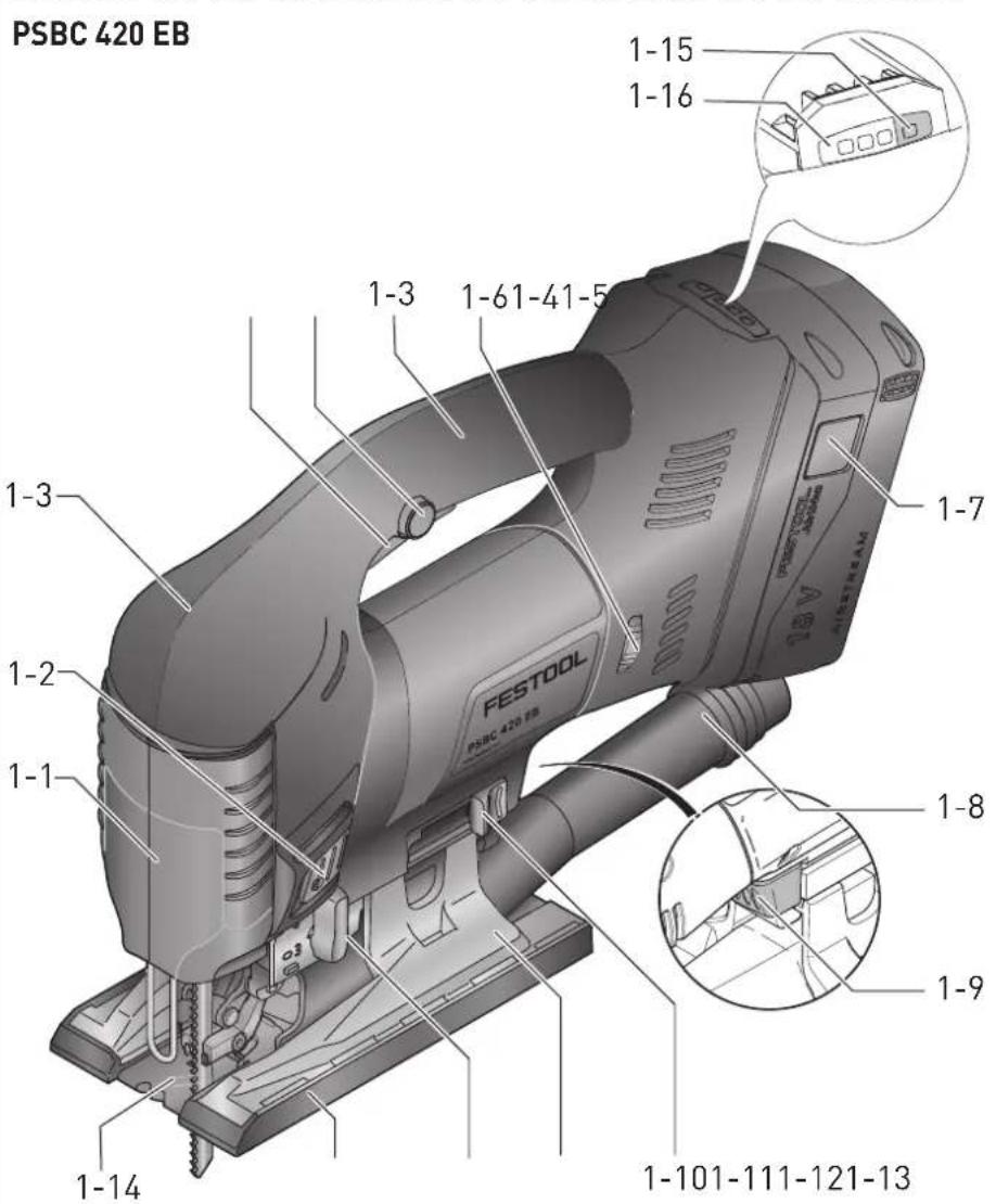
7 Battery pack
▶ Inserting the battery pack [2a]
▶ Removing the battery pack [2b]

Risk of injury! Always remove the belt clip from battery packs from the BPC series prior to use.
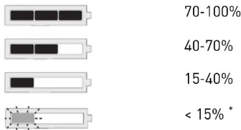
7.1 Capacity display
The capacity display [1-16] indicates the charge of the battery pack for approx. 2 seconds after the button [1-15] is pressed:
bar
| Range | Percentage (%) | |---|---| | 70-100% | 70-100 | | 40-70% | 40-70 | | 15-40% | 15-40 | | < 15% * | < 15% * |* Recommendation: Charge the battery pack before any further use.
i Further information about the charger and battery pack with capacity indicator can be found in the corresponding operating manual.
8 Settings

WARNING
Risk of injury, electric shock
▶ Always disconnect the battery packs from the machine before performing any type of work on the machine!
8.1 Changing tools

CAUTION
Risk of injury from hot and sharp insertion tool
- Do not use any blunt or faulty insertion tools.
- Wear protective gloves when handling an insertion tool.
Selecting the saw blade
Only use saw blades with a T-shank. The saw blade should not be longer than that required for the intended cut. To ensure safe guidance, during the cut the saw blade should emerge at the bottom of the workpiece at every point.
Only use cross-set saw blades when using angle tables and base adapters. We recommend the S 105/4 FSG Festool saw blade.
Festool saw blades for jigsaws are colour-coded. The colour represents the material for which the saw blade is suited.
Colour Material
Yellow Wood
Red Plastics
Green Building materials
Blue Metal
More information can be found on the packaging, in your Festool catalogue or at www.festool.co.uk.
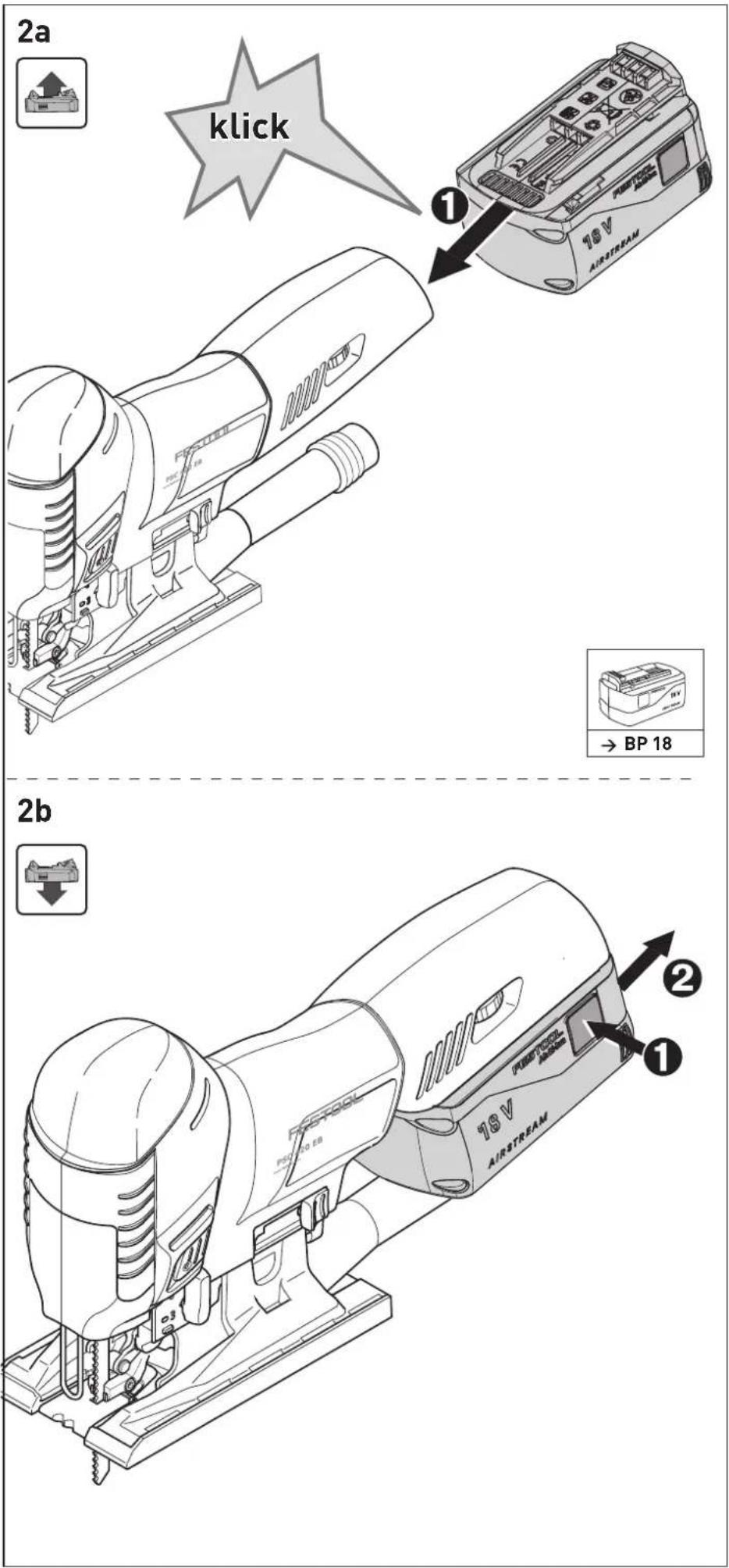
Inserting the saw blade

Always disconnect the power tool from the power supply before changing blades.
▶ If necessary, lift up the chip guard [3-1].
▶ Slide the saw blade [3-4] into the opening [3-2] as far as the stop with its teeth in the cutting direction.
▶ Turn the saw blade [3-4] clockwise by approx. 30^ until it engages.

Check that the saw blade is secure. A loose saw blade can fall out and cause an
If the saw blade is very short, it is advisable to remove the saw table (see section 8.4) before inserting the saw blade.
Adjust the saw blade guide after every saw blade change
The saw blade guide was designed to improve guidance of the saw blade.
▶ Remove the saw table (see section 8.4).
▶ Tighten the screw [3-6] using the hex key [3-5] until the jaws are almost touching the saw blade.
NOTICE
Damage to the machine or saw blade
▶ Do not tighten the screw [3-6] too much. It must be possible to move the saw blade slightly.
Ejecting the saw blade
When ejecting the saw blade, hold the power tool such that no persons or animals can be injured.
▶ Push the saw blade ejection [3-3] forwards as far as the stop.
Saw blade ist thrust out mechanically.
i A tool change is only possible when the tool holder is located in the upper position.
When changing the saw blade is not possible: Let the jigsaw run at a high speed for 3–10 seconds. Actuate the saw blade ejection [3-3] again.
8.2 Using the chip guard
The chip guard [3-1] prevents chips from flying away and improves the efficiency of the chip extraction system.
- Apply slight pressure to push the chip guard [3-1] downwards.
8.3 Inserting the splinterguard
The splinterguard prevents the edges of the material from splintering during the cut, even at the end where the saw blade exits the material.
▶ Switch off the machine and slide the splinterguard [4-1] onto the guide [4-2] and up to the saw blade.
▶ Switch on the jigsaw.
▶ On a level surface, slide in the splinterguard (not using your hand!) while the machine is operating until it is flush with the front edge of the saw table (speed setting 5). This cuts into the splinterguard.
When it is worn, push the splinterguard approx. 3 mm further to the rear and continue using it.
To guarantee reliable operation of the splinterguard, it must seal tightly on both sides of the saw blade. A new splinter-guard should therefore be fitted after every saw blade change to guarantee splinter-free cuts.
8.4 Changing the saw table
▶ Open the change lever [1-9] .
▶ Remove the saw table downwards.
Assembly is performed in reverse sequence to removal. Ensure that the saw table is firmly seated in the guide.
Instead of the saw table, the WT-PS 400 angle table or ADT-PS 400 base adapter can be installed at the support.

Never saw without the saw table, or one of the other tables or adapters offered in stool accessories range.
8.5 Extraction

WARNING
Health risk due to dust
▶ Always work with an extractor.
▶ Comply with national regulations.
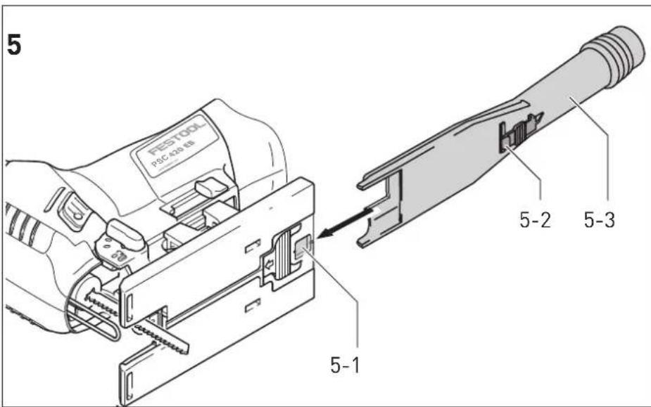
The extraction adapter [5-3] allows jigsaws to be connected to a dust extractor (hose diameter 27 mm).
▶ Insert the extraction adapter in the rear opening of the saw table so that the hook [5-2] engages in the recess [5-1].
▶ To remove the extraction adapter, press the hook [5-2].
(i) Due to the low power consumption of the machine (low energy consumption), dust extractors with an automatic switch-on function will sometimes only start up when the actual cut is made.
- Set the dust extractor to continuous operation for special applications (e.g. low stroke rate, soft wood).
8.6 Adjusting the pendulum stroke
In order to saw different materials with the proper rate of advance the pendulum stroke can be adjusted. Set the required stroke via the pendulum stroke switch [1-12]:
Position 0 = pendulum stroke disabled Position 3 = maximum pendulum stroke
Recommended pendulum stroke setting
Softwood, chip board, wood fibreboard 1 - 3
Blockboard, plywood, plastic 1 - 2
Ceramics 0
Aluminium, non-ferrous metals 0 - 2
Steel, hardwood 0 - 1
8.7 Stroke rate control
Using the adjusting wheel [1-6], the stroke rate can be continuously adjusted between 1500 and 3800 rpm (PSBC 420 EB: 1000–3800 rpm). This enables you to optimise the cutting speed to suit the respective material.
Automatic load detection is activated in position A: The stroke rate drops when idling and is adjusted to the highest setting when the workpiece is introduced.
Recommended stroke rate (position of the adjusting wheel)
Hard and soft wood, blockboard, plywood, chipboard
Fibreboard 4-A
Plastic 3-A
Ceramic, aluminium, non-ferrous metals 3–5
Steel 2-4
9 Working with the electric power tool

CAUTION
Materials which produce a lot of dust Damage to the machine due to the ingress of dust, risk of injury
▶ Do not work overhead.
When working on small or thin workpieces, always use a stable base, or the CMS module (accessory).
English
When working, hold the electric power tool by the handle and guide it along the desired cutting line. For precise cuts and smooth running, use two hands to guide the electric power tool.
9.1 Free saw guidance along a scribe mark
The triangular pointer on the splinterguard [4-1] indicates the cutting line of the saw blade. This facilitates sawing along a scribe mark.
9.2 Lighting

WARNING
Stroboscopic light could lead to misjudgement of the saw blade position
Risk of injury
▶ Ensure the work area is well illuminated.
A steady light or stroboscopic light is installed to illuminate the cutting line:
Up to approx. 2100 rpm: Steady light
From approx. 2100 rpm upwards: Stroboscopic light
① In the overhead position (+/- 45°), the lighting is switched off completely.
If required, you can adjust the lighting:
▶ Plug in the electric power tool.
▶ Press both buttons [1-2] simultaneously and hold for approx. 10 s until a beep sounds.
▶ Release both buttons [1-2].
▶ Press the left button (on the pendulum stroke side) the specified number of times to set the desired mode:
Mode Indication during configuration
Behaviour during operation
1 Light flashes With stroboscope (standard)
2 Light on Steady light without stroboscope
3 Light off Light switched off
▶ Press the right button to save the setting.
9.3 Acoustic warning signals
Acoustic warning signals sound and the machine switches off in the following operating states:

peep — —
Battery flat or machine overloaded.
- Change the battery.
- Place the machine under reduced stress.

peep peep —
Machine is overheating.
- You must allow the machine to cool beforeusing again.

peep peep peep
Lilon battery pack is faulty or has overheated.
- Once the battery pack has cooled, perform a functional check using the charger.
10 Service and maintenance


WARNING
Risk of injury, electric shock
▶ Always remove the battery pack from the power tool before performing any maintenance or service work.
▶ All maintenance and repair work which requires the motor housing to be opened should always be carried out by an authorised service workshop.

Customer service and repairs must only be carried out by the manufacturer or service workshops. Find the nearest address at: www.festool.co.uk/service
Always use original Festool spare parts. Order no. at: www.festool.co.uk/service
10.1 Observe the following information
▶ Check the guidance roller regularly for wear.
▶ Regularly remove dust deposits from the chip guard.
▶ Regularly clean the base runner to prevent scratches and cores on the surface.
▶ Damaged safety devices and components must be repaired or replaced in a recognised specialist workshop, unless otherwise indicated in the operating instructions.
▶ To ensure constant air circulation, always keep the cooling air openings in the motor housing clean and free of blockages.
- Keep the contacts on the power tool, charger and battery pack clean.
10.2 Cleaning the chip ejection opening
Clean the chip ejection opening [1-14] regularly to prevent blockages:
▶ Remove the chip guard.
▶ Use a brush or vacuum cleaner to clean the chip ejection opening.
▶ Reinsert the chip guard.
11 Accessories
The order numbers of the accessories and tools can be found in the Festool catalogue or on the Internet at "www.festool.com".
11.1 Saw blades, other accessories
In order to saw different materials quickly and cleanly, Festool offers saw blades for all applications that are specially designed for your Festool jigsaw.
11.2 Sawing with special base runners
The special base runners protect high-quality surfaces against scratches and scores.
▶ Press in the base runner at position [6-1] .
- At the same time, push the base runner forwards.
▶ Mount another base runner and push it to the rear until it engages.
11.3 Sawing with the angle table

The WT-PS 400 angle table is used for cutting pipes or interior and exterior an-p to 45°.
Dust extraction is not possible when sawing with the angle table!
Installing the angle table
▶ Remove the saw table [1-11] (see section 8.4).
- Position the angle table against the saw base support.
▶ Close the lever [1-9] .
Ensure that the angle table is firmly seated in the guide.
Setting the angle
▶ Turn the adjusting wheel [7-1] to select the required angle.
You can select the angles -45^ , 0^ and +45^ on the scale [7-2].

WARNING
Sawing cutting depths Risk of injury
▶ Select the saw blade length and cutting depth so that the saw blade remains plunged in the workpiece.
For 0^ cuts, we recommend setting the angle table to a small negative angle to guarantee smooth operation.
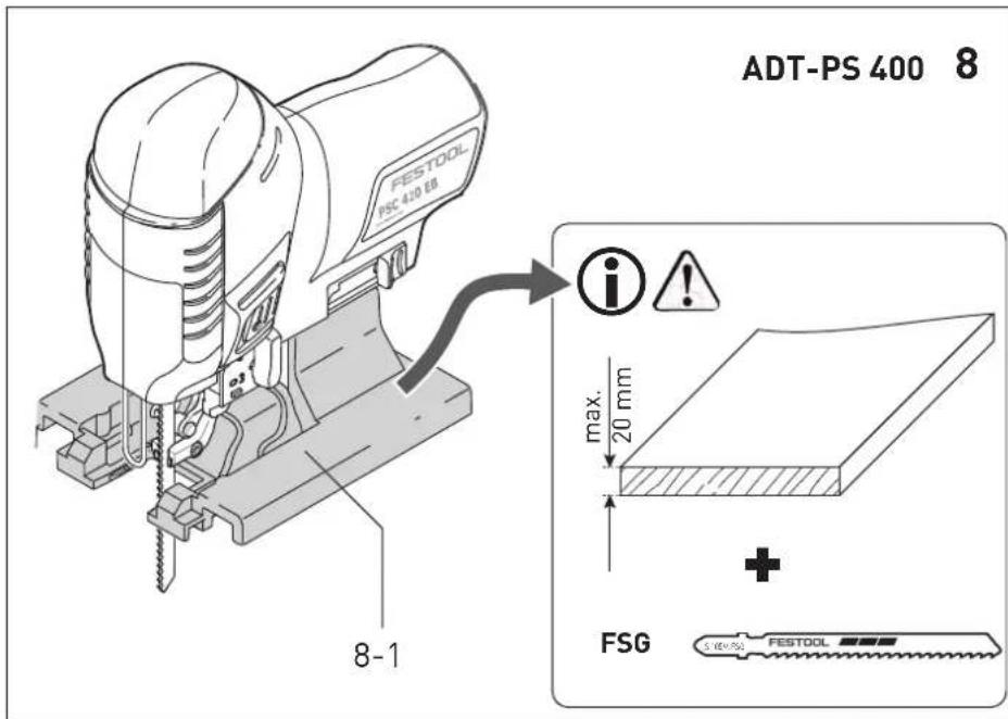
11.4 Sawing with the base adapter
The ADT-PS 400 base adapter is used for attaching your jigsaw to the Festool guide rail and the KS-PS 400 core maker.

With guide rail and core maker: Observe the max. material thickness of 20 mm only use cross-set saw blades (FSG).
Installing the base adapter
▶ Remove the saw table [1-11] (see section 8.4).
▶ Position the base adapter [8-1] against the saw table support.
▶ Close the lever [1-9] .
Ensure that the base adapter is firmly seated in the guide.
i Also use the extractor connector [1-8] with the base adapter.
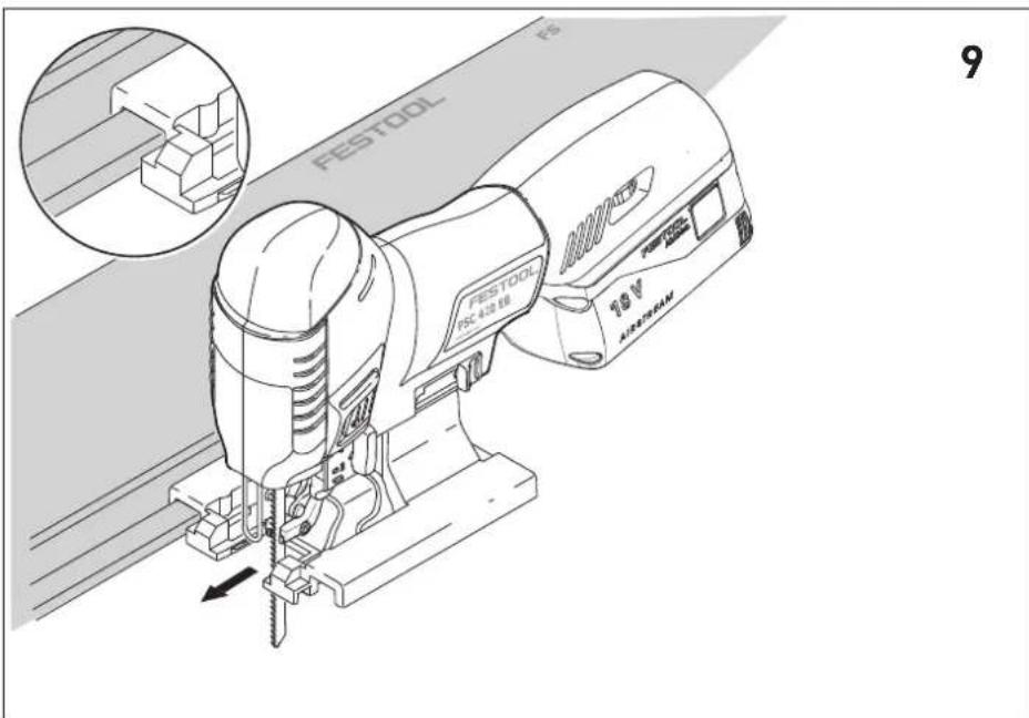
Adaptation to the FS 2 guide rail
The FS 2 Festool guide system (Fig. [9]) makes it much easier to produce straight and precise cuts.
- Place the jigsaw with attached base adapter [8-1] on the guide rail.
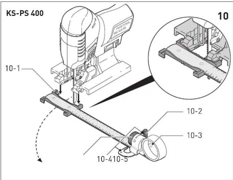
Adaptation to the core maker
The core maker can be used to create circular cuts with a diameter between 120 and 3000 mm. The core maker can be installed from both sides on the base adapter.
▶ Place the jigsaw with attached base adapter on the adapter [10-1] on the core maker.
▶ Insert the centring mandrel [10-2] in the hole [10-4] on the core maker aligned with the saw blade.
▶ Clamp the measuring tape to the core maker using the rotary knob [10-5].
Recommended settings when using the core maker:
▶ Cut in an anticlockwise direction.
▶ Work at a slow rate of advance.
▶ Set the pendulum stroke [1-12] to 0–1.
English
▶ Set the stroke rate [1-6] to 1–5.
i Store the centring mandrel in the depot [10-3].
Semi-stationary sawing with the Festool CMS system
When combined with the Festool CMS system, the jigsaw becomes a semi-stationary bench saw for profiled cuts. See the CMS brochure for more information.
▶ Install your jigsaw with base adapter in the CMS as described in the operating manual for the CMS-PS.
12 Environment

Do not dispose of the device in the household waste! Recycle devices, accessories and packaging. Observe applicable national regulations.
EU only: In accordance with the European Directive on waste electrical and electronic equipment and implementation in national law, used power tools must be collected separately and handed in for environmentally friendly recycling.
Information on REACH: www.festool.com/reach
13 General information
Imported into the UK by
Festool UK Ltd
1 Anglo Saxon Way
Bury St Edmunds
IP30 9XH
Great Britain
13.1 Bluetooth®
The Bluetooth ^® word mark and the logos are registered trademarks of Bluetooth SIG, Inc.; they are used by TTS Tooltechnic Systems AG & Co. KG, and therefore by Festool, under licence.
Sommaire
natural_image
Four black circular icons representing safety and hygiene symbols: helmet, glasses, headphones, and gloves (no text or labels)natural_image
Four horizontal bars with varying internal patterns and a small circular icon at the bottom (no text or symbols)70-100%
40-70%
15-40%
< 15% *
natural_image
Four black circular icons showing different workplace safety symbols: helmet, glasses, headphones, and hand gesture (no text or labels)| 70-100% | |
| 40-70% | |
| 15-40% | |
| < 15% * |
bar
| Range | Percentage (%) | |---|---| | 70-100% | 70-100 | | 40-70% | 40-70 | | 15-40% | 15-40 | | < 15% * | < 15% |bar
| Range | Percentage (%) | |---|---| | 70-100% | 70-100 | | 40-70% | 40-70 | | 15-40% | 15-40 | | < 15% * | < 15% * |2.3 Metallbearbeiding

bar
| Range | Percentage (%) | |---|---| | 70-100% | 70-100 | | 40-70% | 40-70 | | 15-40% | 15-40 | | < 15% * | < 15% |natural_image
Four black circular icons showing different workplace safety symbols: helmet, glasses, headphones, and hand gesture (no text or labels)| 70-100% | |
| 40-70% | |
| 15-40% | |
| < 15% * |
natural_image
Four black circular icons representing different human head positions: face, glasses, headphones, and gloves (no text or symbols)Declaration of Conformity
We as the manufacturer Festool GmbH, Wertstraße 20, 73240 Wendlingen, Germany declare under our sole responsibility that the product(s):
Designation:
Designation of Type(s):
Serial number(s) 1):
Cordless jigsaw
PSC 420 EB, PSBC 420 EB
205259, 205263
fulfills all the relevant provisions of the following UK Regulations:
S.I. 2008/1597
S.I. 2016/1091 ^2
S.I. 2017/1206 ^3)
S.I. 2012/3032
Supply of Machinery (Safety) Regulations 2008
Electromagnetic Compatibility Regulations 2016
Radio Equipment Regulations 2017
Restriction of the Use of Certain Hazardous Substances in Electrical and Electronic Equipment Regulations 2012
and are manufactured in accordance with the following designated standards:
• BS EN 62841-1: 2015
• BS EN 62841-2-11:2016+A1:2020
• BS EN 55014-1:2017 ^2)
• BS EN 55014-2:2015 ^2)
• EN 300 328:2016 V2.1.1 ^3)
• EN 301 489-1:2017 V2.1.1 3)
• EN 301 489-17:2017 V3.1.1 ^3)
• BS EN IEC 63000:2018
1) in the specified serial number range (5-Nr.) from 400000000 - 499999999
21 valid in combination with battery pack BP 18 Li 5,2 AS, BP 18 Li 6,2 AS, BP 18 Li 3,1 C, BP 18 Li 4,0 HPC-AS
3) valid in combination with Bluetooth® battery pack BP 18 Li 5,2 ASI, BP 18 Li 6,2 ASI, BP 18 Li 3,1 Cl, BP 18 Li 4,0 HPC-ASI

Place and date of declaration: Wendlingen, 31.03.2021
Signed on behalf of and in name of Festool GmbH

i.v. Q. Goramdt
Ralf Brandt
Head of Productconformity