Airblade Wash+Dry WD04 - Hand dryer DYSON - Free user manual and instructions
Find the device manual for free Airblade Wash+Dry WD04 DYSON in PDF.
| Product Type | Hand dryer with integrated tap (washing and drying) |
| Brand | Dyson |
| Model | Airblade Wash+Dry WD04 |
| Drying technology | Airblade (high-speed air blades) |
| Power supply | 220-240 V, 50/60 Hz |
| Rated current | 6.6 A |
| Rated power | Approximately 1600 W (refer to rating plate) |
| Standby power consumption | Less than 0.5 W |
| Required water pressure | 1 to 8 bar |
| Water flow rate (standard) | 4 L/min |
| Water flow rate (low flow) | 1.9 L/min (aerator supplied) |
| Operating temperature | 0 to 40 °C |
| Maximum installation altitude | 2000 m |
| Sensor type | Infrared (hand detection for water and air) |
| Washing function | Automatic sensor water, with integrated mixing valve |
| Drying function | High-speed air blades, fast drying |
| Automatic rinse | Yes (60 seconds, 24 hours after last use) |
| Filter | Replaceable (access via motor unit) |
| Recommended cleaning | Clean sensors, dust-free air ducts |
| Installation | Wall-mounted, motor under sink, requires plumbing and electricity |
| Sink compatibility | Porcelain, brushed metal; avoid shiny chrome |
| Included accessories | Flat screwdrivers 7mm and 2.5mm, Torx T15 key, clamps, seals |
| Customer service | Dyson (website www.dyson.fr or www.dysoncanada.ca) |
| Warranty | Refer to product documentation |
Frequently Asked Questions - Airblade Wash+Dry WD04 DYSON
User questions about Airblade Wash+Dry WD04 DYSON
0 question about this device. Answer the ones you know or ask your own.
Ask a new question about this device
Download the instructions for your Hand dryer in PDF format for free! Find your manual Airblade Wash+Dry WD04 - DYSON and take your electronic device back in hand. On this page are published all the documents necessary for the use of your device. Airblade Wash+Dry WD04 by DYSON.
USER MANUAL Airblade Wash+Dry WD04 DYSON
Dyson Customer care www.dyson.com
The source image is extremely blurry and does not clearly contain any legible text. According to Rule 4 (Edge Noise Strategy), no content should be hallucinated. Therefore, the corrected OCR output is:
[No text detected]
Q4 (97) = 307,000
根据《证券法》
6.2 1974-05-03
B. 172800109130
www.drcn.net
SA | 165,726,005,759
www.w.foil.com
SC 1149170254028
www.dtswll.com
买,1-0.64元
- 2017年1月1日
www.nan.com
1993.01.30
www.5000.com
11 1-0228200
www.dysan.co.uk
10 1+20(8)91321144
(1) 2017年1月1日
The English text in the source image is illegible due to extreme blurriness and low resolution. No characters can be confidently identified.
-
- 2018年3月4日
1996年10月28日
01-10557205370
www.youyuan.com
dyson airblade wash+dry

Installation notes
The quick brown fox jumps over the lazy dog.
Important Safety Instructions 5 ⚠
In the box 6
Pre-installation checks 7
Installation
Step-by-step 9
Test installation 11
Troubleshooting 11
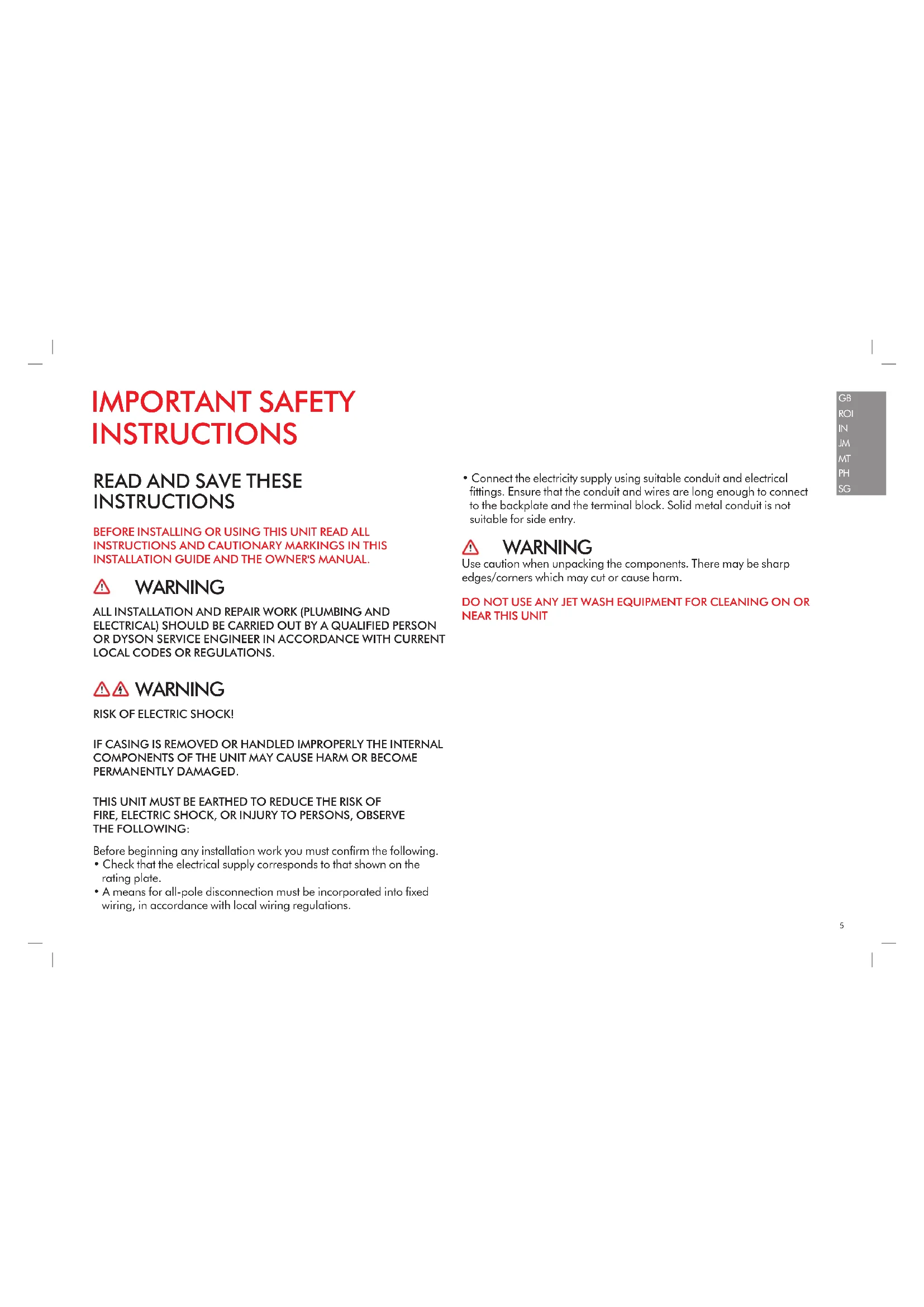
IMPORTANT SAFETY INSTRUCTIONS
READ AND SAVE THESE INSTRUCTIONS
BEFORE INSTALLING OR USING THIS UNIT READ ALL INSTRUCTIONS AND CAUTIONARY MARKINGS IN THIS INSTALLATION GUIDE AND THE OWNER'S MANUAL.
WARNING
ALL INSTALLATION AND REPAIR WORK (PLUMBING AND ELECTRICAL) SHOULD BE CARRIED OUT BY A QUALIFIED PERSON OR DYSON SERVICE ENGINEER IN ACCORDANCE WITH CURRENT LOCAL CODES OR REGULATIONS.
WARNING
RISK OF ELECTRIC SHOCK!
IF CASING IS REMOVED OR HANDLED IMPROPERLY THE INTERNAL COMPONENTS OF THE UNIT MAY CAUSE HARM OR BECOME PERMANENTLY DAMAGED.
THIS UNIT MUST BE EARTHED TO REDUCE THE RISK OF FIRE, ELECTRIC SHOCK, OR INJURY TO PERSONS, OBSERVE THE FOLLOWING:
Before beginning any installation work you must confirm the following.
- Check that the electrical supply corresponds to that shown on the rating plate.
- A means for all-pole disconnection must be incorporated into fixed wiring, in accordance with local wiring regulations.
- Connect the electricity supply using suitable conduit and electrical fittings. Ensure that the conduit and wires are long enough to connect to the backplate and the terminal block. Solid metal conduit is not suitable for side entry.
WARNING
Use caution when unpacking the components. There may be sharp edges/corners which may cut or cause harm.
DO NOT USE ANY JET WASH EQUIPMENT FOR CLEANING ON OR NEAR THIS UNIT
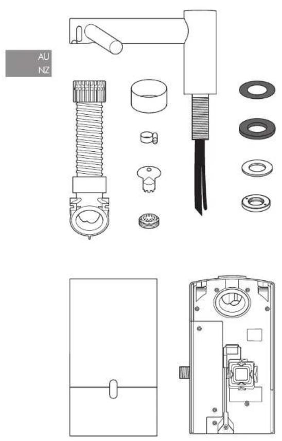
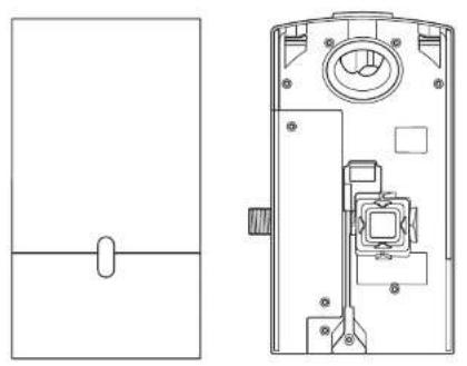
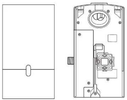
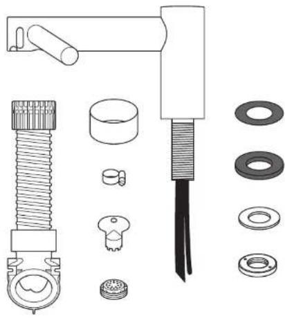
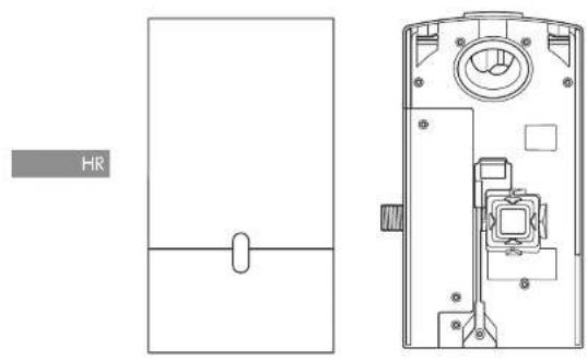
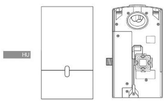
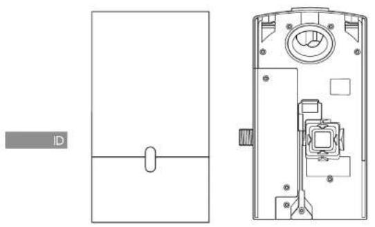
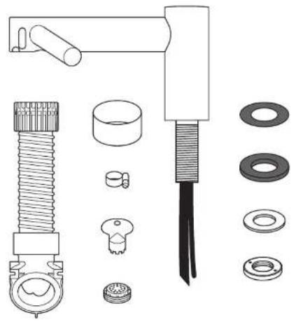
In the box

natural_image
Exploded view diagram of mechanical components including bolts, washers, and a tool (no text or labels)x2


x1


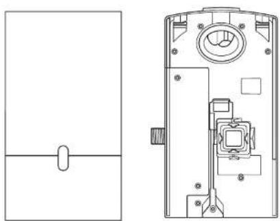
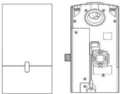
natural_image
Technical line drawing of a door handle and internal components (no text or symbols)Tools required:
Small Phillips screwdriver
7mm slotted screwdriver
2.5mm slotted screwdriver
Torx T15 screwdriver
Tape measure and pencil
Hand drill
Suitable drill bit
Pliers/wire strippers
Knife
Adjustable spanner
Pre-installation checks
Fig. A
Pre-installation planning
The Dyson Airblade Wash+Dry hand dryer is designed so that the motor unit is wall mounted and located under the basin Fig. A(i).
The fitting of an inline filter is advised to prevent any damage that may affect your guarantee.
- Allow sufficient access space for installation and servicing, see Fig. A(ii).
- The unit is designed for a dry, internal location only.
- Consult local and national accessibility codes and regulations for relevant installation guidelines. Conformity and compliance is the responsibility of the installer. Make sure that the unit is installed in compliance with all building codes and/or regulations.
- A means for all-pole disconnection must be incorporated into fixed wiring, in accordance with local wiring regulations.
– Isolate the power and water supplies before installation or service. - Ensure no pipe work (gas, water, air) or electrical cables, wires or ductwork are located directly behind the drilling/mounting area.
- Dyson recommends the use of protective clothing, eye wear and materials when installing/repairing as necessary.
- This appliance is intended to be permanently connected to the water mains.
Use in food preparation areas
For food preparation environments special installation is required, which must fully enclose the motor bucket and hose in a cleanable housing or have the motor bucket on the reverse side of a wall, provide adequate clearance for cleaning underneath (if applicable) and be such that the unit is at least 2.5 metres from uncovered food or uncovered food-contact surfaces.
Refer to the sink recommendation guide at www.dyson.com prior to install.
Fig. B
Sink specification guidelines
Using a specially designed test method, Dyson engineers tested a wide range of sinks to assess their compatibility with the Dyson Airblade Wash+Dry hand dryer. For recommended sinks, please use our guide at www.dyson.com.
Porcelain or brushed metal sinks are ideal. Sinks with highly polished surfaces should be avoided e.g. reflective chrome. For minimum sink dimensions refer to Fig. B,
Fig. C/D/E
Tap mounting
There should be a minimum of 100mm and a maximum of 155mm from the top of the sink to the tap centre Fig. C.
There should be a minimum of 290mm between a tap centre and a side wall. When multiple taps are installed side-by-
side, tap centres should be a minimum of 580mm apart. This allows sufficient space for mounting the motor bucket, as well as sufficient shoulder room for users Fig. D. Do not place the downward facing water sensor of the tap over a reflective surface, such as the drainage hole Fig. E.
Fig. F
Soap and locating the soap dispenser
For best user experience, Dyson recommends the use of gel soap.
The infrared sensing zone for air activation extends along each tap branch. In order to prevent accidental activation, it's important to consider the user's hand route to the soap dispenser.
The dispenser should be located at least 60mm outside the width of the tap, so the user reaches around the side of the branch.
It should also be located at least 60mm above the branches, so that the sensors are not activated.
Please note that the user may reach diagonally across for the soap, so this path must not go through the sensing zone.
Fig. G/H
Water drainage
Due to high velocity air and water being in close proximity, there is a chance of some water and soap dispersion outside the sink dimensions. To alleviate this effect, we recommend following the guidelines below.
Base Profile
Flat base profile will result in poor drainage leading to high levels of splashback. To improve drainage, avoid sinks with a flat base with particular focus on the immediate area surrounding the drain hole, minimum 60mm radius Fig. G.
Minimum of 6^ ramp angle from the edge of the drain hole of the sink will result in good drainage leading to reduced levels of splashback (minimum 60mm radius) Fig. H.
Fig. I/J/K
Base to back and front wall transition
The base to back and front wall transition should also be considered. The back wall should be as close to 90°, and at as sharp a radius as possible Fig. I. Curved geometry is more likely to increase splashback Fig. J, whereas sloping back and front wall transitions should be avoided Fig. K.
Fig. L
Plug hole
Plug holes with the most open aperture are recommended, whereas grill or perforated type plug holes should be avoided as they restrict the drainage of soapy water (lather). Do not use plugs within the plug holes in sinks.
Fig. M
Water temperature control
If you are connecting a hot and cold water feed you will need to install a blender valve. If connecting to cold only water feed you will need to install a heater.
The water supply to this product must be fitted with a temperature control device in accordance with local regulations.
A= Blender valve
B= Hot and cold feed
C = Desired temperature out
D= Isolation valve
E= Hecter
F = Cold feed in
Additional Information
Installing
Do not use sealant when fixing the unit to the wall.
Ensure electricity and mixed water supplies and drainage connections are available for connection. Suitable isolation of the power and water supplies must be in place to switch off supplies before install and for servicing.
Electrical
Input voltage/Frequency: Refer to rating plate. Isolated by switch fuse spur or RCD
as appropriate.
Current 6.6 A.
Cable specification: Dual core PVC + Single core PVC (earth)
Local electrical regulations must be adhered to when installing or repairing the product.
Rated power: Refer to rating plate.
Operating temperature range: 0° – 40°C.
Standby power consumption:
Less than 0.5 W.
Maximum altitude: 2,000 metres.
Water operation
Water flow rate: 1.9 l/m standard fitted aerator. 4 l/min with low flow aerator supplied with product.
Water pressure required: 1-8 bar. 1/2" BSP isolated valve required for service. Keep secondary hot water return as close to blender valve as possible to reduce the risk of Legionella bacteria growth.
Automatic duty flush
The unit is equipped with a fixed automatic water flush, which activates for 60 seconds 24 hours after last use. This helps reduce water stagnation and bacteria proliferation within the product.
Please ensure that the unit is always installed over a functional basin with free and connected drainage.
Water supply cleanliness and
biological growth
In some countries there are regulations or guidelines that require temperature controlled water supply systems (such as that supplied to the Dyson Airblade Wash + Dry hand dryer) to be subjected to regular cleaning to minimise any biological growth. To enable you to meet these regulations, the Dyson Airblade Wash + Dry hand dryer has been designed and tested to withstand internal cleaning both with hot water up to 95°C and with sodium hypochlorite at a concentration of 0.45%.
Please refer to specific (market) regulations and water supply system recommendations for information on cleaning regimes for water supply cleanliness and biological growth for your country.
When carrying out internal cleaning of the Dyson Airblade Wash + Dry hand dryer, please be aware of any safety considerations when using hot water or chemicals. Dyson will not be responsible for any injury caused by this process.
Abusive testing
The Dyson Airblade Wash+Dry hand dryer has undergone rigorous abusive testing to ensure that it can withstand substantial forces and impacts typical of a commercial and public bathroom environment.
Step-by-step
Fig. 1
Position
Position the Tap over the centre of the basin Fig. 1.
Cut a 35 mm diameter hole in the work surface, if required.
Fig. 2
Tap installation
Slide the 1 mm rubber seal on to the tap stem Fig. 2a.
Feed the tap stem and the attached water tube and communications cable through the hole in the work surface. Ensure the 1 mm rubber seal is seated under the tap evenly and flat.
Ensure tap is in the correct position above the sink.
Slide the 3.5mm rubber seal on to the tap stem.
Insert the screws into the brass locking ring and tighten lightly to hold them in place.
Slide the metal washer on to the tap stem.
Screw the brass locking nut on to the top stem, leaving a gap less than or equal to 5mm between the metal washer and the brass locking nut.
Tighten the screws through the brass locking nut into the metal washer, until hand tight.
A=1mm rubber seal
B= Tap stem
C = Water tube
D= Sensor cable
E=3.5mm seal
F= Metal washer
G= Brass locking nut
H=2×screws
Fig. 3
Hose installation
Slide the grey hose up over the water tube and sensor cable Fig. 3a.
Feed the water tube through the left exit hole in the hose duct as shown in Fig. 3b.
Use pliers to gently pull the water tube through as far as the solid white line Fig. 3c.
Ensure the grommet on the water tube fits tightly into the hose duct so that it is airlight Fig. 3b.
Feed the sensor cable through the right exit hole, pulling gently as you feed it through Fig. 3b. DO NOT use pliers as this may damage the electrical connections Fig. 3c. Ensure the grommet on the cable fits tightly into the hose duct so that it is airtight Fig. 3d. Silicone grease may be used to assist with the fitting.
Screw the upper hose collar on to the tap stem so that it is hand tight Fig. 3e.
A= Grey hose
B= Water tube
C = Sensor cable
Fig. 4
Preparing for installation of backplate Remove the motor bucket from the backplate by pressing the red release catch at the bottom and lifting up as shown in Fig. 4a. Store the motor bucket safely until required.
Remove the water pipe cover and the electrics cover from the backplate using a Torx T15 screwdriver Fig. 4b and 4c. Store them safely along with fixings until required.
Fig. 5
Backplate installation planning The backplate can be positioned in one of three ways: vertical, or 90° horizontal left or right. Clearance from the floor should be a 100mm minimum see Fig. 5a.
Ensure that the backplate is positioned so that the hose can be easily attached.
DO NOT place motor upside down with hose pointing down, or position above the Tap see Fig. 5b.
Mark the position of the backplate on the wall.
Cable entry
Cable entry can be either from the base or from the wall directly into the back of the unit via the rear cable entry point. Decide which before you start.
If choosing the cable entry option through the base, use pliers to carefully nip out the pre-marked break-out panel on the base of the backplate. File the edges of the break-out section smooth Fig. 5c.
Water entry
Water connection is made on the left hand side of the backplate. The water connection can not be rotated within the backplate Fig. 5d.
Fig. 6
Backplate installation
If cable entry is to be directly into the backplate from the wall, pull through the electrical cable before securing the backplate to the wall.
Secure the backplate to the wall using the appropriate fixings Fig. 6.
Do not use countersunk screws.
Fig. 7
Connecting the sensor cable
Clip the grey hose into the backplate.
Plug the sensor cable in the hose into the connector in the backplate as shown in Fig. 7. Check the orientation of the connector; the two tabs must be lined up. Ensure the cable is correctly routed in the backplate.
Fig. 8
Connecting the water tube
Cut the water tube to size at the dotted white line as shown in Fig. 8a.
Slide the hose clip (supplied) on to the water tube Fig. 8b.
Remove the 2 x Phillips screws and unclip the solenoid from the backplate Fig. 8b.
Attach the water hose to the solenoid Fig. 8c.
Clip the solenoid back on to the backplate and fasten the 2 x screws Fig. 8d.
Tighten the hose clip and ensure the solenoid cable is correctly positioned in the retaining channel.
Fig. 9
Connecting the electricity supply Route the electricity supply to the backplate using approved flexible or solid conduit and fittings. Ensure the power cable is long enough to connect to the terminal block mounted in the back plate.
Route the cable into the backplate and tighten the cable gland.
Strip the cable to a suitable length and secure the live and neutral wires into the corresponding terminal blocks as shown in Fig. 9. Ensure the correct positioning of the cables before proceeding.
Fig. 10
Re-assemble electrical cover Fix the electrics cover and secure with the 6 x fixings supplied ensuring no wires are trapped.
Fig. 11
Connecting the mixed water supply NOTE: Ensure water feed has been completely flushed of debris, copper filings etc. prior to connecting to the backplate. Failure to do so may damage the solenoid valve.
Connect the isolated, mixed water supply to the backplate.
Turn on the water.
Inspect for leaks at the main water supply inlet and the water tube connection to the tap.
Also check for leaks at the solenoid connection.
Fig. 12
Switching power on Switch on power to the machine.
CALIBRATION CYCLE: Once installed, the tap will go through a 30 second calibration cycle.
Place hand under sensor on tap to activate water flow Fig. 12a.
Check for leaks as per Fig. 11.
Secure the water pipe cover on to the backplate using the 2 x fixings provided Fig 12b.
Fig. 13
Assembling the motor bucket Hook the motor to the top of the electrics cover. Swing it downwards so it clicks into place as shown. Push in securely Fig. 13a.
OPTIONAL: A screw is supplied to secure the red release button and prevent unwanted removal of the motor bucket.
Test the unit for correct operation.
Securing the motor bucket to the backplate (optional).
To remove the filter, gently use a screwdriver to release the tab on the filter as shown Fig. 13b.
Secure the motor bucket to the backplate using the security screw supplied Fig. 13c.
Re-connect the filter ensuring that it clicks into place Fig. 13d.
installation
Test the hand dryer for normal operation:
- Place your hands beneath the centre of the tap and water will flow automatically for as long as the hands remain in place.
- Place your hands to either side of the centre tap to activate the hand dryer, creating sheets of air to scrape water from your hands.
- Move your hands backwards and forwards slowly through the air, turning them over so both back and front are exposed to the airflow.
TroubleshootingTest
Hand dryer fails to start:
- Check fuse/circuit breaker is working and that the power and water supply are connected.
- Ensure the cleaning cap is removed and that the sensors are clean and unobstructed.
– Turn the unit off and on.
Hand dryer turns itself on and off erratically:
– Tum the unit off and on.
- Ensure there is no plug in the sink and remove if plug is present.
– Ensure sensors are clean.
- Check that the sensor cable from the tap is securely connected.
Hand dryer sometimes cuts out in use:
- Turn the unit off and on.
– Ensure sensors are clean.
- Check the air inlets are clean and free of dust. If the air inlets are dusty simply remove dust.
- Ensure that the air inlets are free from obstructions and have sufficient clearance.
The dry time has increased:
- Inspect the air inlets for dust and remove.
– Inspect filter and change if required.
- Ensure that the hose is securely attached to the base of the tap and no leaks are present.
The airflow is running hotter than usual:
– Inspect the air inlets for dust and remove.
– Inspect filter and change if required.
- Ensure that the hose is securely attached to the base of the tap and no leaks are present.
Air is continuously running:
- Check for any object in the sink and remove if necessary.
- Ensure sensors are clean and free from any obstructions.
– Inspect filter and change if required.
- Ensure that the hose is securely attached to the base of the tap and no leaks are present.
There is no air running:
– Turn the unit off and on.
- Check fuse/circuit breaker is working and that the power is connected.
– Ensure sensors are clean.
- Ensure that the air hose is securely attached to the base of the tap and no leaks are present.
- Check that the sensor cable from the tap is securely connected.
Water is continuously coming from the tap:
- Ensure sensors are clean and free from any obstructions.
There is no water coming from the tap:
- Ensure that the power and water supplies are turned on and that the isolation valve is open.
- Ensure that the aerator is free from debris, remove and clean/replace if necessary.
The water coming from the tap is overly hot or cold:
- Check the blender valve is set to the desired temperature.
Contact Dyson Customer Care for further support and information or online at www.dyson.com
AU/NZ
Contents
AU NZ
Important Safety Instructions 13
In the box 14
Pre-installation checks 15
Installation
Step-by-step 17
Test installation 19
Troubleshooting 19
IMPORTANT SAFETY INSTRUCTIONS
READ AND SAVE THESE INSTRUCTIONS
BEFORE INSTALLING OR USING THIS UNIT READ ALL INSTRUCTIONS AND CAUTIONARY MARKINGS IN THIS INSTALLATION GUIDE AND THE OWNERS MANUAL.
WARNING
ALL INSTALLATION AND REPAIR WORK (PLUMBING AND ELECTRICAL) SHOULD BE CARRIED OUT BY A QUALIFIED PERSON OR DYSON SERVICE ENGINEER IN ACCORDANCE WITH CURRENT LOCAL CODES OR REGULATIONS.
WARNING
RISK OF ELECTRIC SHOCK!
IF CASING IS REMOVED OR HANDLED IMPROPERLY THE INTERNAL COMPONENTS OF THE UNIT MAY CAUSE HARM OR BECOME PERMANENTLY DAMAGED.
THIS UNIT MUST BE EARTHED TO REDUCE THE RISK OF FIRE, ELECTRIC SHOCK, OR INJURY TO PERSONS, OBSERVE THE FOLLOWING:
Before beginning any installation work you must confirm the following.
- Check that the electrical supply corresponds to that shown on the rating plate.
- A means for all-pole disconnection must be incorporated into fixed wiring, in accordance with local wiring regulations.
- Connect the electricity supply using suitable conduit and electrical fittings. Ensure that the conduit and wires are long enough to connect to the backplate and the terminal block. Solid metal conduit is not suitable for side entry.
WARNING
Use caution when unpacking the components. There may be sharp edges/corners which may cut or cause harm.
DO NOT USE ANY JET WASH EQUIPMENT FOR CLEANING ON OR NEAR THIS UNIT
In the box
x2


x1


Tools required:
Small Phillips screwdriver
7mm blade screwdriver
Small bladed screwdriver
Torx drive T15
Tape measure and pencil
Hand drill
Suitable drill bit
Pliers/wire strippers
Knife
Adjustable spanner
Pre-installation checks
Fig. A
Pre-installation planning
The Dyson Airblade Wash+Dry hand dryer is designed so that the motor unit is wall mounted and located under the basin Fig. A(i).
The fitting of an inline filter is advised to prevent any damage that may affect your guarantee.
- Allow sufficient access space for installation and servicing, see Fig A(ii). - The unit is designed for dry, internal location only.
- Consult local and national accessibility codes and regulations for relevant installation guidelines. Conformity and compliance is the responsibility of the installer. Make sure that the unit is installed in compliance with all building codes and/or regulations.
- A means for all-pole disconnection must be incorporated into fixed wiring, in accordance with local wiring regulations - Isolate the power and water supplies before installation or service.
- Ensure no pipe work (gas, water, air) or electrical cables, wires or ductwork are located directly behind the drilling/mounting area.
- Dyson recommends the use of protective clothing, eyeware and materials when installing/repairing as necessary.
- This appliance is intended to be permanently connected to the water mains.
Use in food preparation areas
For food preparation environments special installation is required, which must fully enclose the motor bucket and hose in a cleanable housing or have the motor bucket on the reverse side of a wall, provide adequate clearance for cleaning underneath (if applicable) and be such that the unit is at least 2.5 metres from uncovered food or uncovered food-contact surfaces.
Refer to the Sink recommendation guide at www.dyson.com prior to install.
Fig. B
Sink specification guidelines
Using a specially designed test method, Dyson engineers tested a wide range of sinks to assess their compatibility with the Dyson Airblade Wash+Dry hand dryer. For recommended sinks, please use our guide at www.dyson.com.au.
Porcelain or brushed metal sinks are ideal. Sinks with highly polished surfaces should be avoided e.g. reflective chrome.
For minimum sink dimensions refer to Fig. B.
Fig. C/D/E
Tap mounting
There should be a minimum of 100mm and a maximum of 155mm from the top of the sink to the tap centre. Fig. C
There should be a minimum of 290mm between a tap centre and a side wall. When multiple taps are installed side-byside,
tap centres should be a minimum of 580mm apart. This allows sufficient space for mounting the motor bucket, as well as sufficient shoulder room for users. Fig. D Do not place the downward facing water sensor of the tap over a reflective surface, such as the drainage hole. Fig. E
Fig. F
Soap and locating the soap dispenser
For best user experience, Dyson recommends the use of gel soap.
The infrared sensing zone for air activation extends along each tap branch. In order to prevent accidental activation, it's important to consider the user's hand route to the soap dispenser.
The dispenser should be located at least 60mm outside the width of the tap, so the user reaches around the side of the branch.
It should also be located at least 60mm above the branches, so that the sensors are not activated.
Please note that the user may reach diagonally across for the soap, so this path must not go through the sensing zone.
Fig. G/H
Water drainage
Due to high velocity air and water being in close proximity, there is a chance of some water and soap dispersion outside the sink dimensions. To alleviate this effect, we recommend following the guidelines below.
Base Profile
Flat base profile will result in poor drainage leading to high levels of splashback. To improve drainage, avoid sinks with a flat base with particular focus on the immediate area surrounding the drain hole, minimum 60mm radius. Fig. G.
Minimum of 6^ ramp angle from the edge of the drain hole of the sink will result in good drainage leading to reduced levels of splashback (minimum 60mm radius). Fig. H
Fig. I/J/K
Base to back and front wall transition
The base to back and front wall transition should also be considered. The back wall should be as close to 90°, and at as sharp a radius as possible Fig. I. Curved geometry is more likely to increase splashback Fig. J, whereas sloping back and front wall transitions should be avoided Fig. K.
Fig. L
Plug hole
Plug holes with the most open aperture are recommended, whereas grill or perforated type plug holes should be avoided as they restrict the drainage of soapy water (lather). Do not use plugs within the plug holes in sinks.
Fig. M
Water temperature control
If you are connecting a hot and cold water feed you will need to install a thermostatic mixing valve.
If connecting to cold only water feed you will need to install a heater.
The water supply to this product must be fitted with a temperature control device in accordance with local regulations.
A= Thermostatic mixing valve
B= Hot and cold feed
C= Desired temperature out
D= Isolation valve
E= Heater
F = Cold feed in
Additional Information
Installing
Do not use sealant when fixing the unit to the wall.
Ensure electricity and mixed water supplies and drainage connections are available for connection. Suitable isolation of the power and water supplies must be in place to switch off supplies before install and for servicing.
Electrical
Input voltage/Frequency: Refer to rating plate.
Isolated by switch fuse spur or RCD as appropriate.
Current 6.6 A.
Cable specification: Dual core PVC + Single core PVC (earth)
Local electrical regulations must be adhered to when installing or repairing the product. Rated power: Refer to rating plate.
Operating temperature range: 0° – 40°C. Standby power consumption:
Less than 0.5 W.
Maximum altitude: 2,000 metres.
Water operation
Water flow rate: 4 l/min normal fitted aerator. 1.9 l/m with low flow aerator supplied with product.
Water pressure required: 1-8 bar. 1/2" BSP isolated valve required for service.
Keep secondary hot water return as close to thermostatic mixing valve as possible to reduce the risk of Legionella bacteria growth.
Automatic duty flush
The unit is equipped with a fixed automatic water flush, which activates for 60 seconds 24 hours after last use. This helps reduce water stagnation and bacteria proliferation within the product.
Please ensure the unit is always installed over a functional basin with free and connected drainage.
Water supply cleanliness and
biological growth
In some countries there are regulations or guidelines that require temperature controlled water supply systems (such as that supplied to the Dyson Airblade Wash+Dry hand dryer) to be subjected to regular cleaning to minimise any biological growth. To enable you to meet these regulations, the Dyson Airblade Wash+Dry hand dryer has been designed and tested to withstand internal cleaning both with hot water up to 95°C and with sodium hypochlorite at a concentration of 0.45%.
Please refer to specific (market) regulations and water supply system recommendations for information on cleaning regimes for water supply cleanliness and biological growth for your country.
When carrying out internal cleaning of the Dyson Airblade Wash+Dry hand dryer, please be aware of any safety considerations when using hot water or chemicals. Dyson will not be responsible for any injury caused by this process.
Abusive testing
The Dyson Airblade Wash+Dry hand dryer has undergone rigorous abusive testing to ensure that it can withstand substantial forces and impacts typical of a commercial and public bathroom environment.
Step-by-step
Fig. 1
Position
Position the Tap over the centre of the basin Fig. 1.
Cut a 35 mm diameter hole in the work surface, if required.
Fig. 2
Tap installation
Slide the 1mm rubber seal on to the top stem Fig. 2a.
Feed the tap stem and the attached water tube and communications cable through the hole in the work surface. Ensure the 1mm rubber seal is seated under the tap evenly and flat.
Ensure tap is in the correct position above the sink.
Slide the 3.5mm rubber seal on to the tap stem.
Insert the screws into the brass locking ring and tighten lightly to hold them in place.
Slide the metal washer on to the tap stem.
Screw the brass locking nut on to the tap stem, leaving a gap less than or equal to 5mm between the metal washer and the brass locking nut.
Tighten the screws through the brass locking nut into the metal washer, until hand tight.
A= 1mm rubber seal
B=Top stem
C= Water tube
D= Sensor cable
E= 3.5mm seal
F= Metal washer
G= Brass locking nut
H=2×screws
Fig. 3
Hose Installation
Slide the grey hose up over the water tube and sensor cable Fig. 3a.
Feed the water tube through the left exit hole in the hose duct as shown in Fig. 3b.
Use pliers to gently pull the water tube through as far as the solid white line Fig. 3c.
Ensure the grommet on the water tube fits tightly into the hose duct so that it is airtight Fig. 3b.
Feed the sensor cable through the right exit hole, pulling gently as you feed it through Fig. 3b. DO NOT use pliers as this may damage the electrical connections Fig. 3c.
Ensure the grommet on the cable fits tightly into the hose duct so that it is airtight Fig. 3d. Silicone grease may be used to assist with the fitting.
Screw the upper hose collar on to the tap stem so that it is hand tight Fig. 3e.
A = Grey hose
B= Water tube
C= Sensor cable
Fig. 4
Preparing for installation of backplate Remove the motor bucket from the backplate by pressing the red release catch at the bottom and lifting up as shown in Fig. 4a. Store the motor bucket safely until required.
Remove the water pipe cover and the electrics cover from the backplate using a Torx T15 screwdriver Fig. 4b and 4c. Store them safely along with fixings until required.
Fig. 5
Backplate installation
The backplate can be positioned in one of three ways: vertical, or 90° horizontal left or right. Clearance from the floor should be a 100mm minimum see Fig. 5a.
Ensure that the backplate is positioned so that the hose can be easily attached.
DO NOT place motor upside down with hose pointing down, or position above the Tap see Fig. 5b.
Mark the position of the backplate on the wall.
Cable entry
Cable entry can be either from the base or from the wall directly into the back of the unit via the rear cable entry point. Decide which before you start.
If choosing the cable entry option through the base, use pliers to carefully nip out the pre-marked break-out panel on the base of the backplate. File the edges of the break-out section smooth Fig. 5c.
Water entry
Water connection is made on the left hand side of the backplate. The water connection can not be rotated within the backplate Fig. 5d.
Fig. 6
Backplate installation
If cable entry is to be directly into the backplate from the wall, pull through the electrical cable before securing the backplate to the wall.
Secure the backplate to the wall using the appropriate fixings Fig. 6.
Do not use countersunk screws.
Fig. 7
Connecting the sensor cable
Clip the grey hose into the backplate.
Plug the sensor cable in the hose into the connector in the backplate as shown in Fig. 7. Check the orientation of the connector; the two tabs must be lined up. Ensure the cable is correctly routed in the backplate.
Fig. 8
Connecting the water tube
Cut the water tube to size at the dotted white line as shown in Fig. 8a.
Slide the hose clip (supplied) on to the water tube Fig. 8b.
Remove the 2 x Phillips screws and unclip the solenoid from the backplate Fig. 8b. Attach the water hose to the solenoid Fig. 8c.
Clip the solenoid back on to the backplate and fasten the 2 x screws Fig. 8d.
Tighten the hose clip and ensure the solenoid cable is correctly positioned in the retaining channel.
Fig. 9
Connecting the electricity supply Route the electricity supply to the backplate using approved flexible or solid conduit and fittings. Ensure the power cable is long enough to connect to the terminal block mounted in the back plate.
Route the cable into the backplate and tighten the cable gland.
Strip the cable to a suitable length and secure the live and neutral wires into the corresponding terminal blocks as shown in Fig. 9. Ensure the correct positioning of the cables before proceeding.
Fig. 10
Re-assemble electrical cover Fix the electrics cover and secure with the 6 x fixings supplied ensuring no wires are trapped.
Fig. 11
Connecting the mixed water supply NOTE: ensure water feed has been completely flushed of debris, copper filings etc. prior to connecting to the backplate. Failure to do so may damage the solenoid valve resulting in it not closing properly, creating a a dripping tap.
Connect the isolated, mixed water supply to the backplate.
Turn on the water.
Inspect for leaks at the main water supply inlet and the water tube connection to the tap.
Also check for leaks at the solenoid connection.
Fig. 12
Switching power on Switch on power to the machine.
CALIBRATION CYCLE: Once installed, the tap will go through a 30 second calibration cycle.
Place hand under sensor on tap to activate water flow. Fig 12a.
Check for leaks as per Fig. 11.
Secure the water pipe cover onto the backplate using the 2 x fixings provided. Fig 12b.
Fig. 13
Assembling the motor bucket Hook the motor to the top of the electrics cover. Swing it downwards so it clicks into place as shown. Push in securely Fig. 13a.
OPTIONAL: A screw is supplied to secure the red release button and prevent unwanted removal of the motor bucket. Test the unit for correct operation.
Securing the motor bucket to the backplate (optional).
To remove the filter, gently use a screwdriver to release the tab on the filter as shown Fig. 13b.
Secure the motor bucket to the backplate using the security screw supplied Fig. 13c.
Re-connect the filter ensuring that it clicks into place Fig. 13d.
installation
TroubleshootingTest
Test the hand dryer for normal operation:
- Place your hands beneath the centre of the tap and water will flow automatically for as long as the hands remain in place.
- Place your hands to either side of the centre tap to activate the hand dryer, creating sheets of air to scrape water from your hands.
- Move your hands backwards and forwards slowly through the air, turning them over so both back and front are exposed to the airflow.
Hand dryer fails to start:
- Check fuse/circuit breaker is working and that the power and water supply are connected.
- Ensure the cleaning cap is removed and that the sensors are clean and unobstructed.
- Turn the unit off and on.
Hand dryer turns itself on and off erratically:
– Turn the unit off and on.
- Ensure there is no plug in the sink and remove if plug is present.
– Ensure sensors are clean.
- Check that the sensor cable from the tap is securely connected.
Hand dryer sometimes cuts out in use:
– Turn the unit off and on.
– Ensure sensors are clean.
- Check the air inlets are clean and free of dust. If the air inlets are dusty simply remove dust.
- Ensure that the air inlets are free from obstructions and have sufficient clearance.
The dry time has increased:
- Inspect the air inlets for dust and remove.
– Inspect filter and change if required. - Ensure that the hose is securely attached to the base of the tap and no leaks are present.
The airflow is running hotter than usual:
- Inspect the air inlets for dust and remove.
– Inspect filter and change if required. - Ensure that the hose is securely attached to the base of the tap and no leaks are present.
Air is continuously running:
- Check for any object in the sink and remove if necessary.
- Ensure sensors are clean and free from any obstructions.
– Inspect filter and change if required. - Ensure that the hose is securely attached to the base of the tap and no leaks are present.
There is no air running:
– Turn the unit off and on.
- Check fuse/circuit breaker is working and that the power is connected.
– Ensure sensors are clean.
– Ensure that the air hose is securely
attached to the base of the top and no leaks are present.
– Check that the sensor cable from the tap is securely connected.
Water is continuously coming from
the tap:
- Ensure sensors are clean and free from any obstructions.
There is no water coming from the tap:
- Ensure that the power and water supplies are turned on and that the isolation valve is open.
- Ensure that the aerator is free from debris, remove and clean/replace if necessary.
The water coming from the tap is overly hot or cold:
- Check the thermostatic mixing valve is set to the desired temperature.
Contact Dyson Customer Care for further support and information:
Australia Contact: 1800 426 337 or aucustomercare@dyson.com.
www.dyson.com.au
New Zealand contact: 0800 397 667
www.dyson.co.nz
BG
Съдържание
BG
natural_image
Exploded view diagram of mechanical components including bolts, washers, and nuts (no text or labels)x2


x1


natural_image
Technical line drawing of a device interior with internal components and a separate schematic view (no text or symbols)natural_image
Exploded view diagram of mechanical components including bolts, washers, and gears (no text or labels)x2


x1


natural_image
Technical line drawing of a device with internal components and a separate panel view (no text or symbols)Important Safety Instructions 37
In the box 38
Pre-installation checks 39
Installation
Step-by-step 41
Test installation 43
Troubleshooting 43
IMPORTANT SAFETY INSTRUCTIONS
READ AND SAVE THESE INSTRUCTIONS
BEFORE INSTALLING OR USING THIS UNIT READ ALL INSTRUCTIONS AND CAUTIONARY MARKINGS IN THIS INSTALLATION GUIDE AND THE OWNERS MANUAL.
WARNING
ALL INSTALLATION AND REPAIR WORK (PLUMBING AND ELECTRICAL) SHOULD BE CARRIED OUT BY A QUALIFIED PERSON OR DYSON SERVICE ENGINEER IN ACCORDANCE WITH CURRENT LOCAL CODES OR REGULATIONS.
WARNING
RISK OF ELECTRIC SHOCK!
IF CASING IS REMOVED OR HANDLED IMPROPERLY THE INTERNAL COMPONENTS OF THE UNIT MAY CAUSE HARM OR BECOME PERMANENTLY DAMAGED.
TO REDUCE THE RISK OF FIRE, ELECTRIC SHOCK, OR INJURY TO PERSONS, OBSERVE THE FOLLOWING:
Before beginning any installation work you must confirm the following.
- Check that the electrical supply corresponds to that shown on the rating plate.
- A means for all-pole disconnection must be incorporated into fixed wiring, in accordance with local wiring regulations.
- Connect the electricity supply using suitable conduit and electrical fittings. Ensure that the conduit and wires are long enough to connect to the backplate and the terminal block. Solid metal conduit is not suitable for side entry.
WARNING
Use caution when unpacking the components. There may be sharp edges/corners which may cut or cause harm.
DO NOT USE ANY JET WASH EQUIPMENT FOR CLEANING ON OR NEAR THIS UNIT

In the box

natural_image
Exploded view diagram of a mechanical assembly showing exploded views of components like bolts, washers, and gears (no text or labels)x2


x1


natural_image
Technical line drawing of a door handle and internal components (no text or symbols)Tools required:
Small Phillips screwdriver
7mm blade screwdriver
Small bladed screwdriver
Torx drive T15
Tape measure and pencil
Hand drill
Suitable drill bit
Pliers/wire strippers
Knife
Adjustable spanner
Pre-installation checks
Fig. A
Pre-installation planning
The Dyson Airblade Wash+Dry hand dryer is designed so that the motor unit is wall mounted and located under the basin Fig. A(i).
The fitting of an inline filter is advised to prevent any damage that may affect your limited warranty.
- Allow sufficient access space for installation and servicing, see Fig A(ii).
- The unit is designed for dry, internal location only.
- Consult local and national accessibility codes and regulations for relevant installation guidelines. Conformity and compliance is the responsibility of the installer. Make sure that the unit is installed in compliance with all building codes and/or regulations.
- A means for all-pole disconnection must be incorporated into fixed wiring, in accordance with local wiring regulations.
– Isolate the power and water supplies before installation or service. - Ensure no pipe work (gas, water, air) or electrical cables, wires or ductwork are located directly behind the drilling/mounting area.
- Dyson recommends the use of protective clothing, eye wear and materials when installing/repairing as necessary.
- This appliance is intended to be permanently connected to the water mains.
Use in food preparation areas
For food preparation environments special installation is required, which must fully
enclose the motor bucket and hose in a cleanable housing or have the motor bucket on the reverse side of a wall, provide adequate clearance for cleaning underneath (if applicable) and be such that the unit is at least 2.5 metres (8.20 feet) from uncovered food or uncovered food-contact surfaces.
Refer to the Sink recommendation guide at www.dysoncanada.ca prior to install.
Fig. B
Sink specification guidelines
Using a specially designed test method, Dyson engineers tested a wide range of sinks to assess their compatibility with the Dyson Airblade Wash + Dry hand dryer.
For recommended sinks, please use our guide at www.dysoncanada.ca.
Porcelain or brushed metal sinks are ideal. Sinks with highly polished surfaces should be avoided e.g. reflective chrome.
For minimum sink dimensions refer to Fig. B.
Fig. C/D/E
Tap mounting
There should be a minimum of 100mm (3.93 inches) and a maximum of 155mm (6.10 inches) from the top of the sink to the tap centre. Fig. C.
There should be a minimum of 290mm (11.41 inches) between a tap centre and a side wall. When multiple taps are installed side-byside, tap centres should be a minimum of 580mm (22.83 inches) apart. This allows
sufficient space for mounting the motor bucket, as well as sufficient shoulder room for users. Fig. D.
Do not place the downward facing water sensor of the top over a reflective surface, such as the drainage hole. Fig. E,
Fig. F
Soap and locating the soap dispenser For best user experience, Dyson recommends the use of gel soap.
The infrared sensing zone for air activation extends along each tap branch. In order to prevent accidental activation, it's important to consider the user's hand route to the soap dispenser.
The dispenser should be located at least 60mm (2.36 inches) outside the width of the top, so the user reaches around the side of the branch.
It should also be located at least 60mm (2.36 inches) above the branches, so that the sensors are not activated.
Please note that the user may reach diagonally across for the soap, so this path must not go through the sensing zone.
Fig. G/H
Water drainage
Due to high velocity air and water being in close proximity, there is a chance of some water and soap dispersion outside the sink dimensions. To alleviate this effect, we recommend following the guidelines below.
Base Profile
Flat base profile will result in poor drainage leading to high levels of splashback. To improve drainage, avoid sinks with a flat base with particular focus on the immediate area surrounding the drain hole, minimum 60mm (2.36 inches) radius. Fig. C.
Minimum of 6^ ramp angle from the edge of the drain hole of the sink will result in good drainage leading to reduced levels of splashback (minimum 60mm (2.36 inches) radius). Fig. H.
Fig. I/J/K
Base to back and front wall transition
The base to back and front wall transition should also be considered. The back wall should be as close to 90°, and at as sharp a radius as possible Fig. L. Curved geometry is more likely to increase splashback
Fig. J, whereas sloping back and front wall transitions should be avoided Fig. K.
Fig. L
Plug hole
Plug holes with the most open aperture are recommended, whereas grille or perforated type plug holes should be avoided as they restrict the drainage of soapy water (lather). Do not use plugs within the plug holes in sinks.
Fig. M
Water temperature control
If you are connecting a hot and cold water feed you will need to install a blender valve. If connecting to cold only water feed you will need to install a heater.

The water supply to this product must be fitted with a temperature control device in accordance with local regulations.
A= Blender valve
B= Hot and cold feed
C= Desired temperature out
D= Isolation valve
E=Heater
F = Cold feed in
Additional Information
Installing
Do not use sealant when fixing the unit to the wall.
Ensure electricity and mixed water supplies and drainage connections are available for connection. Suitable isolation of the power and water supplies must be in place to switch off supplies before install and for servicing.
Electrical
Input voltage/Frequency: Refer to rating plate. Isolated by switch fuse spur or RCD
as appropriate.
Current 6.6 A.
Local electrical regulations must be adhered to when installing or repairing the product. Rated power: Refer to rating plate.
Operating temperature range: 0° – 40°C.
Standby power consumption:
Less than 0.5 W.
Maximum altitude: 2,000 metres.
Water operation
Water flow rate: 4 l/min normal fitted aerator. 1.9 l/m with low flow aerator supplied with product.
Water pressure required: 1-8 bar. 3.8 cm (1.5 inches) BSP isolated valve required for service.
Keep secondary hot water return as close to blender valve as possible to reduce the risk of Legionella bacteria growth.
Automatic duty flush
The unit is equipped with a fixed automatic water flush, which activates for 60 seconds 24 hours after last use. This helps reduce water stagnation and bacteria proliferation within the product.
Please ensure the unit is always installed over a functional basin with free and connected drainage.
Water supply cleanliness and
biological growth
In some countries there are regulations or guidelines that require temperature controlled water supply systems (such as that supplied to the Dyson Airblade Wash+Dry hand dryer) to be subjected to regular cleaning to minimise any biological growth. To enable you to meet these regulations, the Dyson Airblade Wash+Dry hand dryer has been designed and tested to withstand internal cleaning both with hot water up to 95°C and with sodium hypochlorite at a concentration of 0.45%.
Please refer to specific (market) regulations and water supply system recommendations for information on cleaning regimes for water supply cleanliness and biological growth for your country.
When carrying out internal cleaning of the Dyson Airblade Wash + Dry hand dryer, please be aware of any safety considerations when using hot water or chemicals. Dyson Canada will not be responsible for any injury caused by this process.
Abusive testing
The Dyson Airblade Wash+Dry hand dryer has undergone rigorous abusive testing to ensure that it can withstand substantial forces and impacts typical of a commercial and public bathroom environment.
Step-by-step
Fig. 1
Position
Position the Tap over the centre of the basin Fig. 1.
Cut a 35 mm diameter hole in the work surface, if required.
Fig. 2
Tap installation
Slide the 1 mm rubber seal on to the tap stem Fig. 2a.
Feed the tap stem and the attached water tube and communications cable through the hole in the work surface. Ensure the 1 mm rubber seal is seated under the tap evenly and flat.
Ensure tap is in the correct position above the sink.
Slide the 3.5mm rubber seal on to the tap stem.
Insert the screws into the brass locking ring and tighten lightly to hold them in place.
Slide the metal washer on to the tap stem.
Screw the brass locking nut on to the top stem, leaving a gap less than or equal to 5mm between the metal washer and the brass locking nut.
Tighten the screws through the brass locking nut into the metal washer, until hand fight.
A= 1mm rubber seal
B=Top stem
C = Water tube
D= Sensor cable
E=3.5mm seal
F= Metal washer
G= Brass locking nut
H=2×screws
Fig. 3
Hose Installation
Slide the grey hose up over the water tube and sensor cable Fig. 3a.
Feed the water tube through the left exit hole in the hose duct as shown in Fig. 3b.
Use pliers to gently pull the water tube through as far as the solid white line Fig. 3c.
Ensure the grommet on the water tube fits tightly into the hose duct so that it is airlight Fig. 3b.
Feed the sensor cable through the right exit hole, pulling gently as you feed it through Fig. 3b. DO NOT use pliers as this may damage the electrical connections Fig. 3c. Ensure the grommet on the cable fits tightly into the hose duct so that it is airtight Fig. 3d. Silicone grease may be used to assist with the fitting.
Screw the upper hose collar on to the tap stem so that it is hand tight Fig. 3e.
A= Grey hose
B= Water tube
C = Sensor cable
Fig. 4
Preparing for installation of backplate Remove the motor bucket from the backplate by pressing the red release catch at the bottom and lifting up as shown in Fig. 4a. Store the motor bucket safely until required.
Remove the water pipe cover and the electrics cover from the backplate using a Torx T15 screwdriver Fig. 4b and 4c. Store them safely along with fixings until required.
Fig. 5
Backplate installation
The backplate can be positioned in one of three ways: vertical, or 90° horizontal left or right. Clearance from the floor should be a 100mm minimum see Fig. 5a.
Ensure that the backplate is positioned so that the hose can be easily attached.
DO NOT place motor upside down with hose pointing down, or position above the Tap see Fig. 5b.
Mark the position of the backplate on the wall.
Cable entry
Cable entry can be either from the base or from the wall directly into the back of the unit via the rear cable entry point. Decide which before you start.
If choosing the cable entry option through the base, use pliers to carefully nip out the pre-marked break-out panel on the base of the backplate. File the edges of the break-out section smooth Fig. 5c.
Water entry
Water connection is made on the left hand side of the backplate. The water connection can not be rotated within the backplate Fig. 5d.
Fig. 6
Backplate installation
If cable entry is to be directly into the backplate from the wall, pull through the electrical cable before securing the backplate to the wall.
Secure the backplate to the wall using the appropriate fixings Fig. 6.
Do not use countersunk screws.
Fig. 7
Connecting the sensor cable
Clip the grey hose into the backplate.
Plug the sensor cable in the hose into the connector in the backplate as shown in Fig. 7. Check the orientation of the connector; the two tabs must be lined up. Ensure the cable is correctly routed in the backplate.
Fig. 8
Connecting the water tube
Cut the water tube to size at the dotted white line as shown in Fig. 8a.
Slide the hose clip (supplied) on to the water tube Fig. 8b.

Remove the 2 x Phillips screws and unclip the solenoid from the backplate Fig. 8b.
Attach the water hose to the solenoid Fig. 8c.
Clip the solenoid back on to the backplate and fasten the 2 x screws Fig. 8d.
Tighten the hose clip and ensure the solenoid cable is correctly positioned in the retaining channel.
Fig. 9
Connecting the electricity supply Route the electricity supply to the backplate using approved flexible or solid conduit and fittings. Ensure the power cable is long enough to connect to the terminal block mounted in the back plate.
Route the cable into the backplate and tighten the cable gland.
Strip the cable to a suitable length and secure the live and neutral wires into the corresponding terminal blocks as shown in Fig. 9. Ensure the correct positioning of the cables before proceeding.
Fig. 10
Re-assemble electrical cover Fix the electrics cover and secure with the 6 x fixings supplied ensuring no wires are trapped.
Fig. 11
Connecting the mixed water supply Ensure water feed has been completely flushed of debris, copper filings etc. prior to connecting to the backplate. Failure to do so may damage the solenoid valve resulting in it not closing properly, creating a a dripping tap. Connect the isolated, mixed water supply to the backplate.
Turn on the water.
Inspect for leaks at the main water supply inlet and the water tube connection to the tap.
Also check for leaks at the solenoid connection.
Fig. 12
Switching power on Switch on power to the machine.
CALIBRATION CYCLE: Once installed, the tap will go through a 30 second calibration cycle.
Place hand under sensor on tap to activate water flow. Fig. 12a.
Check for leaks as per Fig. 11.
Secure the water pipe cover onto the backplate using the 2 x fixings provided. Fig 12b.
Fig. 13
Assembling the motor bucket Hook the motor to the top of the electrics cover. Swing it downwards so it clicks into place as shown. Push in securely Fig. 13a.
OPTIONAL: A screw is supplied to secure the red release button and prevent unwanted removal of the motor bucket.
Test the unit for correct operation.
Securing the motor bucket to the backplate (optional). To remove the filter, gently use a screwdriver to release the tab on the filter as shown Fig. 13b.
Secure the motor bucket to the backplate using the security screw supplied Fig. 13c.
Re-connect the filter ensuring that it clicks into place Fig. 13d.
installation
TroubleshootingTest
Test the hand dryer for normal operation:
- Place your hands beneath the centre of the tap and water will flow automatically for as long as the hands remain in place.
- Place your hands to either side of the centre tap to activate the hand dryer, creating sheets of air to scrape water from your hands.
- Move your hands backwards and forwards slowly through the air, turning them over so both back and front are exposed to the airflow.
Hand dryer fails to start:
- Check fuse/circuit breaker is working and that the power and water supply are connected.
- Ensure the cleaning cap is removed and that the sensors are clean and unobstructed.
– Turn the unit off and on.
Hand dryer turns itself on and off erratically:
- Turn the unit off and on.
- Ensure there is no plug in the sink and remove if plug is present.
- Ensure sensors are clean.
- Check that the sensor cable from the tap is securely connected.
Hand dryer sometimes cuts out in use:
– Turn the unit off and on.
– Ensure sensors are clean.
- Check the air inlets are clean and free of dust. If the air inlets are dusty simply remove dust.
- Ensure that the air inlets are free from obstructions and have sufficient clearance.
The dry time has increased:
- Inspect the air inlets for dust and remove. - Inspect filter and change if required.
- Ensure that the hose is securely attached to the base of the tap and no leaks are present.
The airflow is running hotter than usual:
- Inspect the air inlets for dust and remove.
- Inspect filter and change if required.
- Ensure that the hose is securely attached to the base of the tap and no leaks are present.
Air is continuously running:
- Check for any object in the sink and remove if necessary.
– Ensure sensors are clean and free from any obstructions.
- Inspect filter and change if required.
- Ensure that the hose is securely attached to the base of the tap and no leaks are present.
There is no air running:
- Turn the unit off and on.
- Check fuse/circuit breaker is working and that the power is connected.
- Ensure sensors are clean.
– Ensure that the air hose is securely
attached to the base of the top and no leaks are present.
– Check that the sensor cable from the tap
is securely connected.
Water is continuously coming from the tap:
- Ensure sensors are clean and free from any obstructions.
There is no water coming from the tap:
- Ensure that the power and water supplies are turned on and that the isolation valve is open.
- Ensure that the aerator is free from debris, remove and clean/replace if necessary.
The water coming from the tap is overly hot or cold:
- Check the blender valve is set to the desired temperature.
Contact Dyson Customer Care for further support and information or online at www.dysoncanada.ca

CAFR
Contenu
natural_image
Exploded view diagram of mechanical components including bolts, washers, and a tool (no text or labels)x2


x1


natural_image
Technical line drawing of a door handle and internal components (no text or symbols)Outils nécessaires
Petit tournevis cruciforme
Recommendations relatives aux
specifications du lavabo
natural_image
Exploded view diagram of mechanical components including bolts, washers, and a tool (no text or labels)x2


x1


natural_image
Technical line drawing of a door handle and internal components (no text or symbols)Požadované nářadi:
natural_image
Exploded view diagram of mechanical components including bolts, washers, and a tool (no text or labels)x2


x1


natural_image
Technical line drawing of a door panel with internal components and a side view (no text or symbols)natural_image
Technical diagram of a mechanical assembly with exploded and assembled views (no text or labels)x2


x1


Nødvendigt værktøj:
Montering of vandhane
Installation of slange
natural_image
Exploded view diagram of mechanical components including bolts, washers, and a screwdriver (no text or labels)x2


x1


natural_image
Technical line drawing of a device rear panel and internal components (no text or symbols)natural_image
Exploded view diagram of a mechanical assembly showing exploded view of components like bolt, washer, and washers (no text or labels)x2


x1


FI

natural_image
Technical line drawing of a device rear panel and internal components (no text or symbols)natural_image
Exploded view diagram of mechanical components including bolts, washers, and a tool (no text or labels)x2


x1


Outils requis :
Petit tournevis cruciforme
natural_image
Exploded view diagram of mechanical components including bolts, washers, and a screwdriver (no text or labels)x2


x1


natural_image
Exploded view diagram of mechanical components including bolts, washers, and a tool (no text or labels)x2


x1


natural_image
Technical line drawing of a door panel and internal components (no text or symbols)118
Potreban alat:
Mali križni odvijač Phillips
natural_image
Exploded view diagram of mechanical components including bolts, washers, and a tool (no text or labels)x2


x1


natural_image
Technical line drawing of a door panel and internal mechanism (no text or symbols)126
natural_image
Exploded view diagram of mechanical components including bolts, washers, and a screwdriver (no text or labels)x2


x1


natural_image
Technical line drawing of a door panel and internal mechanism (no text or symbols).Е This is a nuclear nuclear nuclear nuclear nuclear nuclear nuclear nuclear nuclear nuclear nuclear nuclear nuclear nuclear nuclear nuclear nuclear nuclear nuclear nuclear nuclear nuclear nuclear nuclear nuclear nuclear nuclear nuclear nuclear nuclear nuclear nuclear nuclear nuclear nuclear nuclear nuclear nuclear nuclear nuclear nuclear nuclear nuclear nuclear nuclear nuclear nuclear nuclear nuclear nuclear nuclear nuclear nuclear nuclear nuclear nuclear nuclear nuclear nuclear nuclear nuclear nuclear nuclear nuclear nuclear nuclear nuclear nuclear nuclear nuclear nuclear nuclear nuclear nuclear nuclear nuclear nuclear nuclear nuclear nuclear nuclear nuclear nuclear nuclear nuclear nuclear nuclear nuclear nuclear nuclear nuclear nuclear nuclear nuclear nuclear nuclear nuclear nuclear nuclear nuclear Nuclear
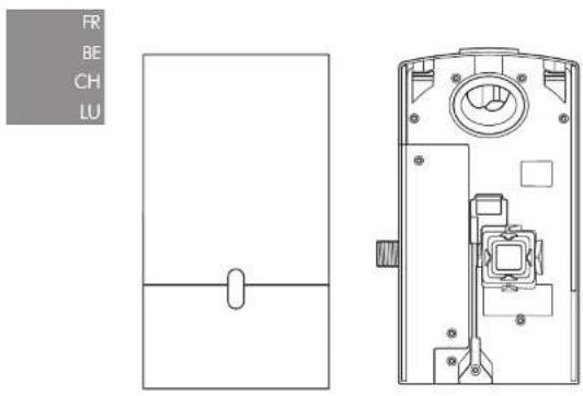
F
natural_image
Exploded view diagram of mechanical components including bolts, washers, and a tool (no text or labels)
natural_image
Simple line drawing of a rectangular shape with a vertical oval cutout at the bottom (no text or symbols)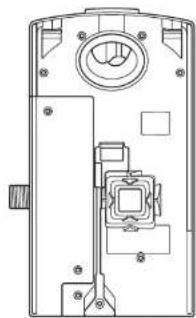
natural_image
Technical line drawing of a mechanical device with internal components and mounting holes (no text or symbols)
natural_image
Exploded view diagram of a mechanical assembly showing exploded view of components like bolts, washers, and nuts (no text or labels)x2


x1


natural_image
Technical line drawing of a door panel and internal components (no text or symbols)natural_image
Exploded view diagram of mechanical components including bolts, washers, and nuts (no text or labels)x2


x1


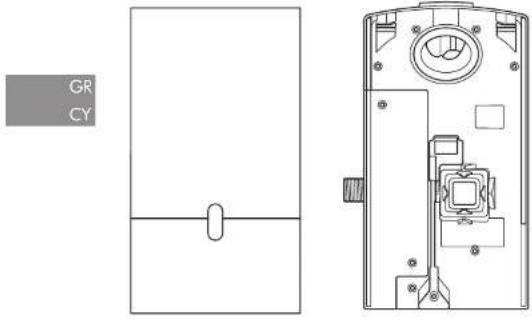
158

natural_image
Simple line drawing of a rectangular frame with a horizontal line and an oval cutout at the center (no text or symbols)
natural_image
Technical line drawing of a mechanical device interior (no text or symbols)Strumenti necessari:
Cacciovite piccolo Phillips
natural_image
Exploded view diagram of a mechanical assembly showing exploded views of components like bolts, washers, and nuts (no text or labels)x2


x1


natural_image
Technical line drawing of a door handle and internal components (no text or symbols)必要なツール:
小プラスドライバー
7mm プレードスクリュードライバー
2.5mmマイナスドライバー
T15トルクスドライバー
テープメジャーと鉛筆
ハンドドリル
適切なドリル用ビット
ペンチ / ワイヤーストリッパー
カッターナイフ
スバナー
取り付け前の確認事項
图 A
取り付け前の確認事項
natural_image
Exploded view diagram of a mechanical assembly showing exploded views of components like bolts, washers, and nuts (no text or labels)x2


x1


natural_image
Technical line drawing of a door panel with internal components and a side view (no text or symbols)174
필요한 공구:
소형 십자 드라이버
7mm 일자 드라이버
2.5mm일자 드라이버
T15별 드라이버
줄자 및 연필
핸드 드림
적합한 드림 비트
펜치/와이어 스트리퍼
칼
조절식 스패너
설치 전 확인사항
그림 A
설치 전 준비
natural_image
Exploded view diagram of mechanical components including bolts, washers, and nuts (no text or labels)x2


x1


natural_image
Technical line drawing of a device rear panel and internal components (no text or symbols)Alatan diperlukan:
natural_image
Exploded view diagram of a mechanical assembly showing exploded views of components like bolts, washers, and nuts (no text or labels)x2


x1


natural_image
Technical line drawing of a door panel with internal components and a side view (no text or symbols)190
natural_image
Exploded view diagram of mechanical components including bolts, washers, and a tool (no text or labels)x2


x1


natural_image
Technical line drawing of a device rear panel and internal components (no text or symbols)198
Verktøy som trengs:
Lite stjerneskrujern
Additional Information
Installasjon
Check for leaks as per Fig. 11.
Dem Treatment Management (Aid)
DÔLEŽITÉ BEZPEČNOSTNÉ POKYNY
TIETO POKYNY SI PREČÍTAJTE A USCHOVAJTE
PRED MONTÁŽOU ALEBO POUŽITÍM TOHTO ZARIADENIA SI PREČÍTAJTE VŠETKY POKYNY A VAROVNÉ OZNAČENIA V TEJTO INŠTALAČNEJ PRÍRUČKE A V NÁVODE NA OBSLUHU.
VAROVANIE
VŠETKY MONTÁŽNE PRÁCE A OPRAVY (INŠTALATÉRSKE A ELEKTRIKÁRSKE) MUSÍ VYKONAT KVALIFIKOVANÁ OSOBA ALEBO SERVISNÝ TECHNIK SPOLOČNOSTI DYSON V SÚLADE S PLATNÝMI PREDPISMI ALEBO NARIADENIAMI.
VAROVANIE
NEBEZPEČENSTVO ÚRAZU ELEKTRICKÝM PRÚDOM!
V PRÍPADE NESPRÁVNEJ DEMONTÁŽE KRYTU ALEBO MANIPULÁCIE MÔŽU VNÚTORNÉ ČASTI PRÍSTROJA SPÓSOBIŤ PORANENIE ALEBO SA MÔŽU TRVALO POŠKODIŤ.
NA ZNÍŽENIE RIZIKA VZNIKU POŽIARU, ÚRAZU ELEKTRICKÝM PRÚDOM ALEBO ZRANENIA OSÓB MUSÍ BYŤ ZARIADENIE UZEMNENÉ.
natural_image
Exploded view diagram of mechanical components including bolts, washers, and a tool (no text or labels)x2


x1


natural_image
Technical line drawing of a device with internal components and a separate schematic view (no text or symbols)Zahtevana orodja:
natural_image
Exploded view diagram of a mechanical assembly showing exploded views of components like bolts, washers, and washers (no text or labels)x2


x1


อุปกรณีต้องเชิง
ไสตวงเจกขนาดเส็ก
7
2.5 mm
T15
สายวัดและตินสอ
ล่ว่านมือ
ตอกลว่านรู้เหมาะสม
คืน / ตําดับทางไฟ
云
LYSUNINOU

natural_image
Technical line drawing of a device rear panel and internal components (no text or symbols)( Dyson Airblade Wash - Dry ) ( 95% )
The image is too blurry to recognize any text content.
natural_image
Exploded view diagram of a mechanical assembly showing exploded view of components like bolt, washer, and washers (no text or labels)x2


x1


TR

natural_image
Technical line drawing of a device rear panel and internal components (no text or symbols)280
Gerekli aletler:
natural_image
Exploded view diagram of mechanical components including bolts, washers, and a tool (no text or labels)x2


x1


所需工具:
小型十字螺絲起子
7 mm 一字螺絲起子
2.5mm一字螺絲起子
梅花穴 T15 螺絲起子
捲尺與鉛筆
重鑽
合適的鑽頭
钳子/剝線鉗
小刀
可调整的扳手
安裝前檢查
圖 A
安装前规划
natural_image
Exploded view diagram of mechanical components including bolts, washers, and a tool (no text or labels)x2


x1


natural_image
Technical line drawing of a door panel and internal mechanism (no text or symbols)Important Safety Instructions 303
In the box 304
Pre-installation checks 305
Installation
Step-by-step 307
Test installation 309
Troubleshooting 309
IMPORTANT SAFETY INSTRUCTIONS
READ AND SAVE THESE INSTRUCTIONS
BEFORE INSTALLING OR USING THIS UNIT READ ALL INSTRUCTIONS AND CAUTIONARY MARKINGS IN THIS INSTALLATION GUIDE AND THE OWNERS MANUAL.
WARNING
ALL INSTALLATION AND REPAIR WORK (PLUMBING AND ELECTRICAL) SHOULD BE CARRIED OUT BY A QUALIFIED PERSON OR DYSON SERVICE TECHNICIAN IN ACCORDANCE WITH CURRENT LOCAL CODES OR REGULATIONS.
WARNING
RISK OF ELECTRIC SHOCK!
IF CASING IS REMOVED OR HANDLED IMPROPERLY THE INTERNAL COMPONENTS OF THE UNIT MAY CAUSE HARM OR BECOME PERMANENTLY DAMAGED.
TO REDUCE THE RISK OF FIRE, ELECTRIC SHOCK, OR INJURY TO PERSONS, OBSERVE THE FOLLOWING:
Before beginning any installation work you must confirm the following.
- Check that the electrical supply corresponds to that shown on the rating plate.
- A means for all-pole disconnection must be incorporated into fixed wiring, in accordance with local wiring regulations.
- Connect the electricity supply using suitable conduit and electrical fittings. Ensure that the conduit and wires are long enough to connect to the backplate and the terminal block. Solid metal conduit is not suitable for side entry.
WARNING
Use caution when unpacking the components. There may be sharp edges/corners which may cut or cause harm.
DO NOT USE ANY JET WASH EQUIPMENT FOR CLEANING ON OR NEAR THIS UNIT
In the box
natural_image
Exploded view diagram of mechanical components including bolts, washers, and a tool (no text or labels)x2


x1


natural_image
Simple line drawing of a rectangular frame with a horizontal line and an oval cutout at the center (no text or symbols)
natural_image
Technical line drawing of a mechanical device interior (no text or symbols)Tools required:
Small Phillips screwdriver
7mm blade screwdriver
Small bladed screwdriver
Torx T15 screwdriver
Tape measure and pencil
Hand drill
Suitable drill bit
Pliers/wire strippers
Knife
Adjustable spanner
Pre-installation checks
Fig. A
Pre-installation planning
The Dyson Airblade Wash+Dry hand dryer is designed so that the motor unit is wall mounted and located under the basin Fig. A(i).
The fitting of an inline filter is advised to prevent any damage that may affect your limited warranty.
-Allow sufficient access space for installation and servicing, see Fig. A(ii).
- The unit is designed for dry, internal location only.
-Consult local and national accessibility codes and regulations for relevant installation guidelines. Conformity and compliance is the responsibility of the installer. Make sure that the unit is installed in compliance with all building codes and/or regulations.
-A means for all-pole disconnection must be incorporated into fixed wiring, in accordance with local wiring regulations. -Isolate the power and water supplies before installation or service.
- Ensure no pipe work (gas, water, air) or electrical cables, wires or ductwork are located directly behind the drilling/mounting area.
—Dyson recommends the use of protective clothing, eye wear and materials when installing/repairing as necessary.
- This appliance is intended to be permanently connected to the water mains.
Use in food preparation areas
For food preparation environments special installation is required, which must fully enclose the motor bucket and hose in a cleanable housing or have the motor bucket on the reverse side of a wall, provide adequate clearance for cleaning underneath (if applicable) and be such that the unit is at least 8 feet from uncovered food or uncovered food-contact surfaces.
Refer to the Sink recommendation guide at www.dyson.com prior to install.
Fig. B
Sink specification guidelines
Using a specially designed test method, Dyson engineers tested a wide range of sinks to assess their compatibility with the Dyson Airblade Wash+Dry hand dryer. For recommended sinks, please use our guide at www.dyson.com.
Porcelain or brushed metal sinks are ideal. Sinks with highly polished surfaces should be avoided e.g. reflective chrome. For minimum sink dimensions refer to Fig. B,
Fig. C/D/E
Tap mounting
There should be a minimum of 4" and a maximum of 6" from the top of the sink to the tap center. Fig. C.
There should be a minimum of 11" between a tap center and a side wall. When multiple taps are installed side-by-side, tap centers
should be a minimum of 23" apart. This allows sufficient space for mounting the motor bucket, as well as sufficient shoulder room for users. Fig. D.
Do not place the downward facing water sensor of the tap over a reflective surface, such as the drainage hole. Fig. E.
Fig. F
Soap and locating the soap dispenser
For best user experience, Dyson recommends the use of gel soap.
The infrared sensing zone for air activation extends along each tap branch. In order to prevent accidental activation, it's important to consider the user's hand route to the soap dispenser.
The dispenser should be located at least 2" outside the width of the tap, so the user reaches around the side of the branch.
It should also be located at least 2" above the branches, so that the sensors are not activated.
Please note that the user may reach diagonally across for the soap, so this path must not go through the sensing zone.
Fig. G/H
Water drainage
Due to high velocity air and water being in close proximity, there is a chance of some water and soap dispersion outside the sink dimensions. To alleviate this effect, we recommend following the guidelines below.
Base Profile
Flat base profile will result in poor drainage leading to high levels of splashback. To improve drainage, avoid sinks with a flat base with particular focus on the immediate area surrounding the drain hole, minimum 2° radius, Fig. C.
Minimum of 6^ ramp angle from the edge of the drain hole of the sink will result in good drainage leading to reduced levels of splashback (minimum 2^ radius). Fig. H.
Fig. I/J/K
Base to back and front wall transition
The base to back and front wall transition should also be considered. The back wall should be as close to 90°, and at as sharp a radius as possible Fig. I. Curved geometry is more likely to increase splashback Fig. J, whereas sloping back and front wall transitions should be avoided Fig. K.
Fig. L
Plug hole
Plug holes with the most open aperture are recommended, whereas grille or perforated type plug holes should be avoided as they restrict the drainage of soapy water (lather). Do not use plugs within the plug holes in sinks.
Fig. M
Water temperature control
If you are connecting a hot and cold water feed you will need to install a blender valve. If connecting to cold only water feed you will need to install a heater.
The water supply to this product must be fitted with a temperature control device in accordance with local regulations.
A= Blender valve
B= Hot and cold feed
C= Desired temperature out
D= Isolation valve
E=Heater
F = Cold feed in
Additional Information
Installing
Do not use sealant when fixing the unit to the wall.
Ensure electricity and mixed water supplies and drainage connections are available for connection. Suitable isolation of the power and water supplies must be in place to switch off supplies before install and for servicing.
Electrical
Input voltage/Frequency: Refer to rating plate. Isolated by switch fuse spur or RCD
as appropriate.
Current 6.6 A.
Local electrical regulations must be adhered to when installing or repairing the product. Rated power: Refer to rating plate.
Operating temperature range: 32° – 104°F.
Standby power consumption:
Less than 0.5 W.
Maximum altitude: 6500'.
Water operation
Water flow rate: 0.5 gal/min normal fitter aerator, 0.35 gal/min with low flow aerato supplied with product.
Water pressure required: 14.5-116 psi isolated valve required for service.
Keep secondary hot water return as close to blender valve as possible to reduce the risk of Legionella bacteria growth.
Automatic duty flush
The unit is equipped with a fixed automatic water flush, which activates for 60 seconds every 24 hours after last use. This helps reduce water stagnation and bacteria proliferation within the product.
Please ensure the unit is always installed over a functional sink with free and connected drainage.
Water supply cleanliness and
biological growth
In some countries there are regulations or guidelines that require temperature controlled water supply systems (such as that supplied to the Dyson Airblade Wash+Dry hand dryer) to be subjected to regular cleaning to minimize any biological growth. To enable you to meet these regulations, the Dyson Airblade Wash+Dry hand dryer has been designed and tested to withstand internal cleaning both with hot water up to 203°F and with sodium hypochlorite at a concentration of 0.45%.
Please refer to specific (market) regulations and water supply system recommendations for information on cleaning regimes for water supply cleanliness and biological growth for your country.
When carrying out internal cleaning of the Dyson Airblade Wash + Dry hand dryer, please be aware of any safety considerations when using hot water or chemicals. Dyson will not be responsible for any injury caused by this process.
Abusive testing
The Dyson Airblade Wash+Dry hand dryer has undergone rigorous abusive testing to ensure that it can withstand substantial forces and impacts typical of a commercial and public bathroom environment.
Step-by-step
Fig. 1
Position
Position the Tap over the center of the basin Fig. 1.
Cut a 1.37 inches (35 mm) diameter hole in the work surface, if required.
Fig. 2
Tap installation
Slide the 0.04 inches (1 mm) rubber seal on to the tap stem Fig. 2a.
Feed the tap stem and the attached water tube and communications cable through the hole in the work surface. Ensure the 0.04 inches (1 mm) rubber seal is seated under the tap evenly and flat.
Ensure tap is in the correct position above the sink.
Slide the 0.14 inches (3.5 mm) rubber seal on to the tap stem.
Insert the screws into the brass locking ring and tighten lightly to hold them in place.
Slide the metal washer on to the tap stem.
Screw the brass locking nut on to the top stem, leaving a gap less than or equal to 0.20 inches (5 mm) between the metal washer and the brass locking nut.
Tighten the screws through the brass locking nut into the metal washer, until hand fight.
A= 0.04 inches (1 mm) rubber seal
B=Top stem
C = Water tube
D= Sensor cable
E= 0.14 inches (3.5 mm) seal
F= Metal washer
G= Brass locking nut
H=2×screws
Fig. 3
Hose Installation
Slide the grey hose up over the water tube and sensor cable Fig. 3a.
Feed the water tube through the left exit hole in the hose duct as shown in Fig. 3b.
Use pliers to gently pull the water tube through as far as the solid white line Fig. 3c.
Ensure the grommet on the water tube fits tightly into the hose duct so that it is airtight Fig. 3b.
Feed the sensor cable through the right exit hole, pulling gently as you feed it through Fig. 3b. DO NOT use pliers as this may damage the electrical connections Fig. 3c. Ensure the grommet on the cable fits tightly into the hose duct so that it is airtight Fig. 3d. Silicone grease may be used to assist with the fitting.
Screw the upper hose collar on to the tap stem so that it is hand tight Fig. 3e.
A = Grey hose
B= Water tube
C= Sensor cable
Fig. 4
Preparing for installation of backplate Remove the motor bucket from the backplate by pressing the red release catch at the bottom and lifting up as shown in Fig. 4a. Store the motor bucket safely until required.
Remove the water pipe cover and the electrics cover from the backplate using a Torx T15 screwdriver Fig. 4b and 4c. Store them safely along with fixings until required.
Fig. 5
Backplate installation
The backplate can be positioned in one of three ways: vertical, or 90° horizontal left or right. Clearance from the floor should be a 3.93 inches (100 mm) minimum see Fig. 5a.
Ensure that the backplate is positioned so that the hose can be easily attached.
DO NOT place motor upside down with hose pointing down, or position above the Tap see Fig. 5b.
Mark the position of the backplate on the wall.
Cable entry
Cable entry can be either from the base or from the wall directly into the back of the unit via the rear cable entry point. Decide which before you start.
If choosing the cable entry option through the base, use pliers to carefully nip out the pre-marked break-out panel on the base of the backplate. File the edges of the break-out section smooth Fig. 5c.
Water entry
Water connection is made on the left hand side of the backplate. The water connection can not be rotated within the backplate Fig. 5d.
Fig. 6
Backplate installation
If cable entry is to be directly into the backplate from the wall, pull through the electrical cable before securing the backplate to the wall.
Secure the backplate to the wall using the appropriate fixings Fig. 6.
Do not use countersunk screws.
Fig. 7
Connecting the sensor cable
Clip the grey hose into the backplate.
Plug the sensor cable in the hose into the connector in the backplate as shown in Fig. 7. Check the orientation of the connector; the two tabs must be lined up. Ensure the cable is correctly routed in the backplate.
Fig. 8
Connecting the water tube Cut the water tube to size at the dotted white line as shown in Fig. 8a.
Slide the hose clip (supplied) on to the water tube Fig. 8b.
Remove the 2 x Phillips screws and unclip the solenoid from the backplate Fig. 8b.
Attach the water hose to the solenoid Fig. 8c.
Clip the solenoid back on to the backplate and fasten the 2 x screws Fig. 8d.
Tighten the hose clip and ensure the solenoid cable is correctly positioned in the retaining channel.
Fig. 9
Connecting the electricity supply Route the electricity supply to the backplate using approved flexible or solid conduit and fittings. Ensure the power cable is long enough to connect to the terminal block mounted in the back plate.
Route the cable into the backplate and tighten the cable gland.
Strip the cable to a suitable length and secure the live and neutral wires into the corresponding terminal blocks as shown in Fig. 9. Ensure the correct positioning of the cables before proceeding.
Fig. 10
Re-assemble electrical cover Fix the electrics cover and secure with the 6 x fixings supplied ensuring no wires are trapped.
Fig. 11
Connecting the mixed water supply Ensure water feed has been completely flushed of debris, copper filings etc. prior to connecting to the backplate. Failure to do so may damage the solenoid valve resulting in it not closing properly, creating a a dripping tap.
Connect the isolated, mixed water supply to the backplate.
Turn on the water. Inspect for leaks at the main water supply inlet and the water tube connection to the tap.
Also check for leaks at the solenoid connection.
Fig. 12
Switching power on Switch on power to the machine.
CALIBRATION CYCLE: Once installed, the tap will go through a 30 second calibration cycle.
Place hand under sensor on tap to activate water flow. Fig. 12a.
Check for leaks as per Fig. 11.
Secure the water pipe cover onto the backplate using the 2 x fixings provided. Fig. 12b.
Fig. 13
Assembling the motor bucket Hook the motor to the top of the electrics cover. Swing it downwards so it clicks into place as shown. Push in securely Fig. 13a.
OPTIONAL: A screw is supplied to secure the red release button and prevent unwanted removal of the motor bucket.
Test the unit for correct operation.
Securing the motor bucket to the backplate (optional).
To remove the filter, gently use a screwdriver to release the tab on the filter as shown Fig. 13b.
Secure the motor bucket to the backplate using the security screw supplied Fig. 13c.
Re-connect the filter ensuring that it clicks into place Fig. 13d.
installation
Test the hand dryer for normal operation:
—Place your hands beneath the center of the tap and water will flow automatically for as long as the hands remain in place.
—Place your hands to either side of the center tap to activate the hand dryer, creating sheets of air to scrape water from your hands.
-Move your hands backwards and forwards slowly through the air, turning them over so both back and front are exposed to the airflow.
TroubleshootingTest
Hand dryer fails to start:
-Check fuse/circuit breaker is working and that the power and water supply are connected.
—Ensure the cleaning cap is removed and that the sensors are clean and unobstructed.
-Turn the unit off and on.
Hand dryer turns itself on and off erratically:
-Turn the unit off and on.
- Ensure there is no plug in the sink and remove if plug is present.
—Ensure sensors are clean.
-Check that the sensor cable from the tap is securely connected.
Hand dryer sometimes cuts out in use:
-Turn the unit off and on.
-Ensure sensors are clean.
- Check the air inlets are clean and free of dust. If the air inlets are dusty simply remove dust.
- Ensure that the air inlets are free from obstructions and have sufficient clearance.
The dry time has increased:
-Inspect the air inlets for dust and remove.
-Inspect filter and change if required.
—Ensure that the hose is securely attached to the base of the tap and no leaks are present.
The airflow is running hotter than usual:
-Inspect the air inlets for dust and remove. -Inspect filter and change if required.
-Ensure that the hose is securely attached to the base of the tap and no leaks are present.
Air is continuously running:
- Check for any object in the sink and remove if necessary.
- Ensure sensors are clean and free from any obstructions.
-Inspect filter and change if required.
—Ensure that the hose is securely attached to the base of the tap and no leaks are present.
There is no air running:
—Turn the unit off and on.
- Check fuse/circuit breaker is working and that the power is connected.
—Ensure sensors are clean.
- Ensure that the air hose is securely attached to the base of the tap and no leaks are present.
- Check that the sensor cable from the tap is securely connected.
Water is continuously coming from the tap:
- Ensure sensors are clean and free from any obstructions.
There is no water coming from the tap:
- Ensure that the power and water supplies are turned on and that the isolation valve is open.
- Ensure that the aerator is free from debris, remove and clean/replace if necessary.
The water coming from the tap is overly hot or cold:
-Check the blender valve is set to the desired temperature.
Contact Dyson Customer Care for further support and information or online at www.dyson.com
USES/AR/CL/GT/MX/PA
Contenido
Installation Drawings
Схеми За Монтаж
D
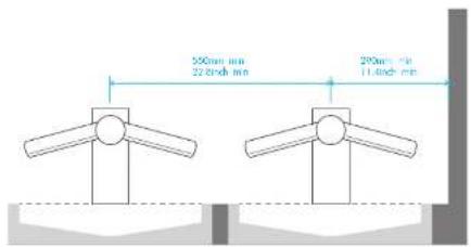
E
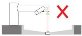
F
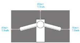
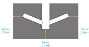
G
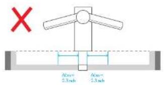
H
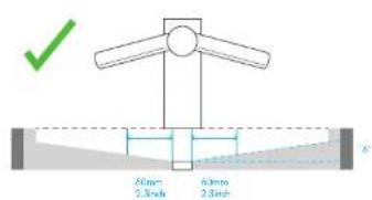
|
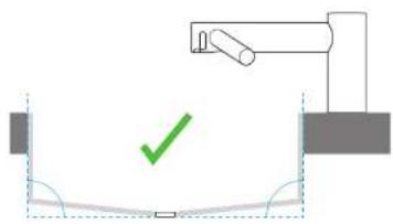
natural_image
Simple diagram showing a mechanical setup with a green checkmark and a vertical line, no text or symbols present.JKL
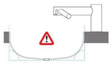
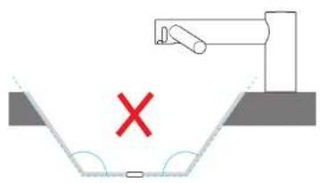
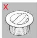
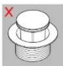
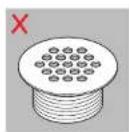
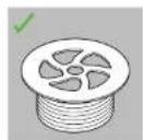
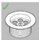
M
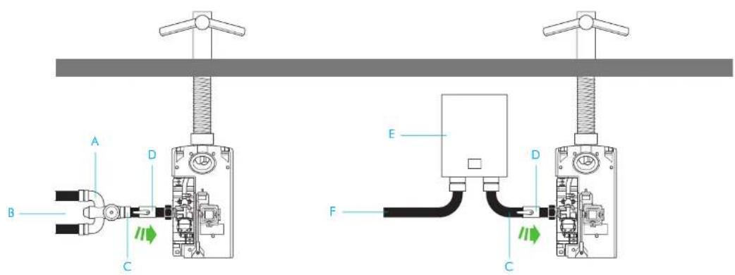
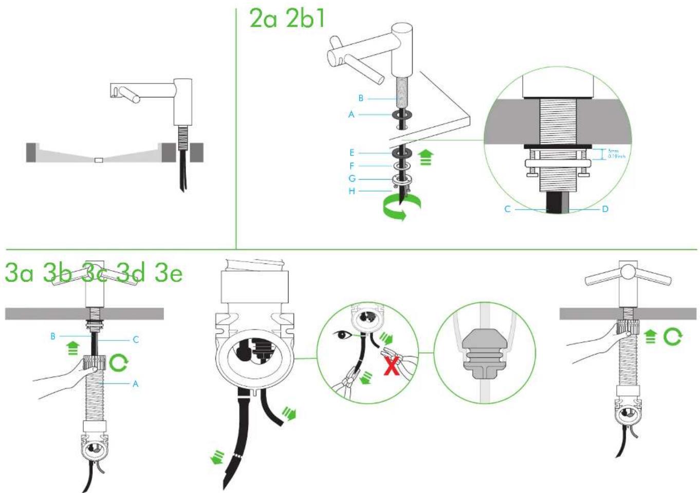
4a 4b 4c
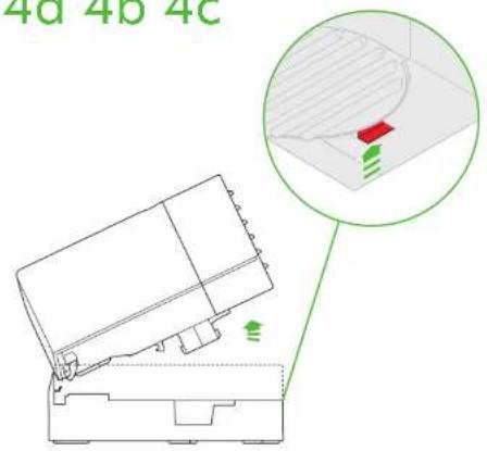
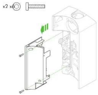
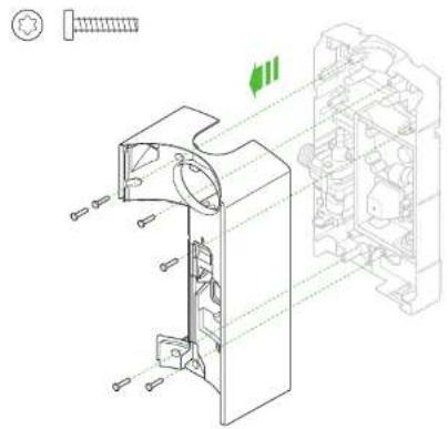
natural_image
Technical line drawing of a mechanical assembly with exploded view and internal components (no text or symbols)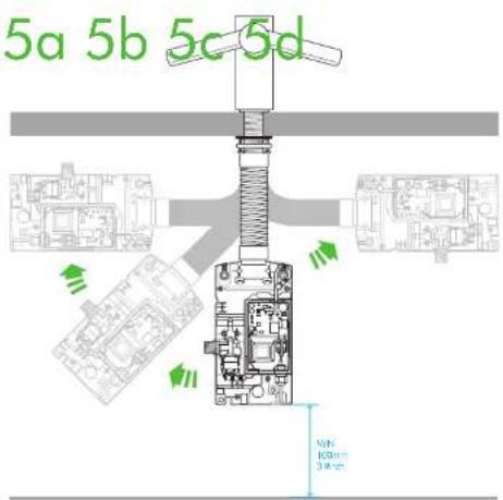
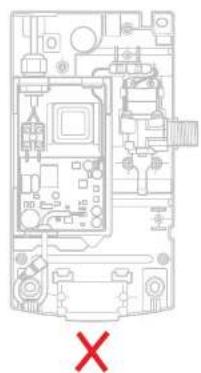
natural_image
Interior view of a computer room with visible circuitry and labeled components (no readable text or symbols)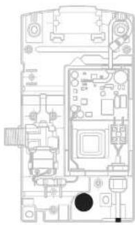
natural_image
Top-down schematic of a computer motherboard showing CPU socket, RAM slots, and drive bays (no text or labels)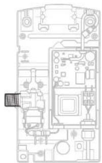
natural_image
Top-down schematic of a device casing with internal components and connectors (no text or labels)6
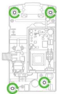
7
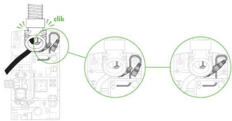
8a 8b 8c
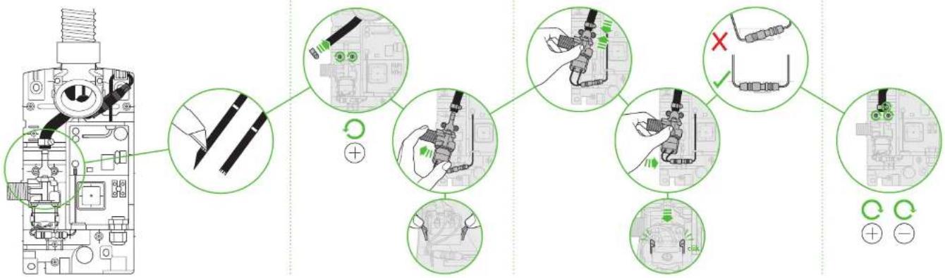
flowchart
graph TD
    A["Engine with screw"] --> B["Switch"]
    B --> C{Switch Path Changes}
    C -->|Yes| D["Adjusting to switch"]
    C -->|No| E["Adjusting to fault"]
    D --> F["Switch to circuit"]
    E --> G["Switch to circuit"]
    F --> H["Electrical Control Signals"]
    G --> I["Electrical Control Signals"]
    H --> J["Switch to circuit"]
    I --> K["Switch to circuit"]
8d
9 10
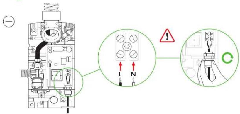
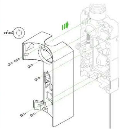
natural_image
Technical line drawing of a mechanical assembly with cross-sectional view (no text or symbols)11
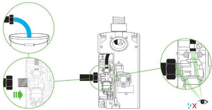
12a
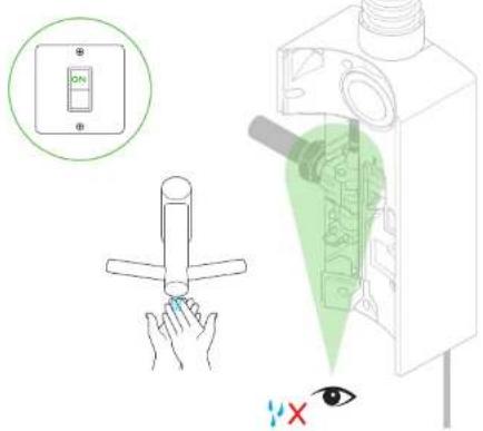
12b
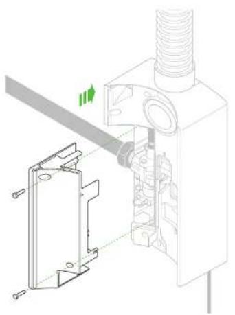
natural_image
Technical diagram of a mechanical assembly with a bracket and pipe connection (no text or symbols)13a 13b
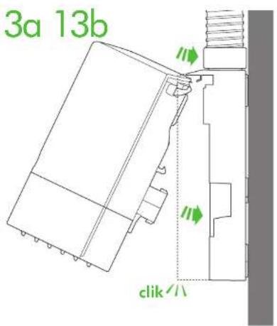
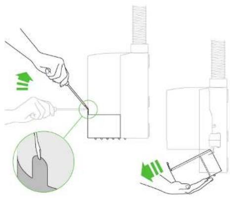
natural_image
Illustration of a hand using a tool to adjust or install a mechanical component, with no visible text or symbols.13c 13d 14
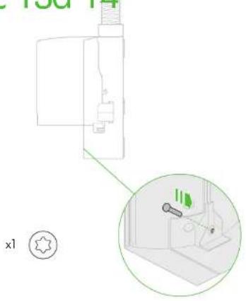
natural_image
Diagram of a kitchen appliance with a close-up inset showing a tool interacting with a sink (no text or symbols present)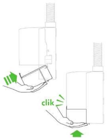
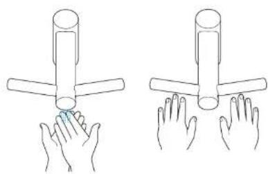
natural_image
Illustration of two hands holding a cylindrical object, no text or symbols presentDyson Customer care www.dyson.com
UK (+44) 0800 345 7788 www.dyson.co.uk
ROI (+353) 01 401 8300 www.dyson.ie
AE (+971) 4 507 6000 www.dyson.ae
AR (+1) 855 720 6378 www.dyson.com.ar
AT (+43) 0800 8866 7343 www.dyson.at
AU (+61) 1800 426 337 www.dyson.com.au
BE (+32) 0800 39 209 www.dyson.be
BG (+359) 2 968 1111 www.dyson.bg
BH (+971) 4 507 6000 www.dyson.ae