Airblade Wash+Dry WD06 - Hand dryer DYSON - Free user manual and instructions
Find the device manual for free Airblade Wash+Dry WD06 DYSON in PDF.
| Product Type | Hand dryer with integrated tap (wash and dry) |
| Brand | Dyson |
| Model | Airblade Wash+Dry WD06 |
| Power supply | 220-240 V ~ 50/60 Hz, 6.6 A |
| Rated power | 1600 W (estimated) |
| Standby consumption | Less than 0.5 W |
| Required water pressure | 1 to 8 bar |
| Water flow rate | 4 L/min (standard aerator), 1.9 L/min (low flow aerator) |
| Air type | High-speed air blades |
| Sensors | Infrared for water and air activation |
| Automatic rinse | Yes, 60 seconds 24 hours after last use |
| Protection rating | IP35 |
| Operating temperature | 0 to 40 °C |
| Maximum altitude | 2,000 m |
| Materials | Metal, plastic |
| Installation | Wall-mounted, requires plumbing and electricity |
| Maintenance | Daily cleaning of sensors and surfaces; regular cleaning of air intake |
| Filter | HEPA (replaceable) |
| Warranty | 5 years |
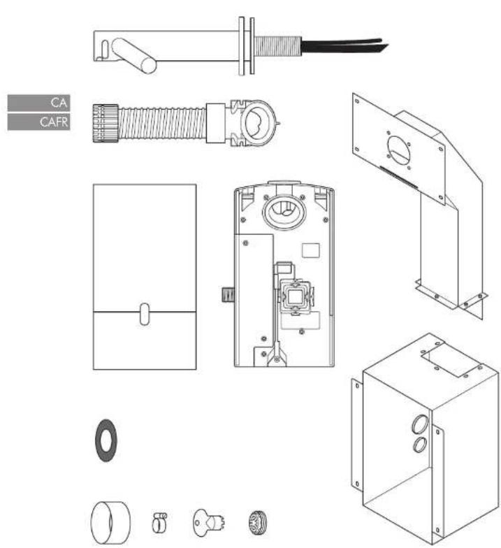
| Box contents | Motor unit, back plate, tap, hose, fixings, low flow aerator, template |
Frequently Asked Questions - Airblade Wash+Dry WD06 DYSON
User questions about Airblade Wash+Dry WD06 DYSON
0 question about this device. Answer the ones you know or ask your own.
Ask a new question about this device
Download the instructions for your Hand dryer in PDF format for free! Find your manual Airblade Wash+Dry WD06 - DYSON and take your electronic device back in hand. On this page are published all the documents necessary for the use of your device. Airblade Wash+Dry WD06 by DYSON.
USER MANUAL Airblade Wash+Dry WD06 DYSON
Dyson Customer care www.dyson.com
PT | 10T 30C 784 106
The source image is extremely blurry and does not clearly contain any legible text. According to Rule 4 (Edge Noise Strategy), no content should be hallucinated. Therefore, the corrected OCR output is:
Important Safety Instructions 5 ⚠
In the box 6
Pre-installation checks 7
Installation
Step-by-step 9
Test installation 10
Troubleshooting 10
IMPORTANT SAFETY INSTRUCTIONS
READ AND SAVE THESE INSTRUCTIONS
BEFORE INSTALLING OR USING THIS UNIT READ ALL INSTRUCTIONS AND CAUTIONARY MARKINGS IN THIS INSTALLATION GUIDE AND THE OWNER'S MANUAL.
WARNING
ALL INSTALLATION AND REPAIR WORK (PLUMBING AND ELECTRICAL) SHOULD BE CARRIED OUT BY A QUALIFIED PERSON OR DYSON SERVICE ENGINEER IN ACCORDANCE WITH CURRENT LOCAL CODES OR REGULATIONS.
WARNING
RISK OF ELECTRIC SHOCK!
IF CASING IS REMOVED OR HANDLED IMPROPERLY THE INTERNAL COMPONENTS OF THE UNIT MAY CAUSE HARM OR BECOME PERMANENTLY DAMAGED.
THIS UNIT MUST BE EARTHED TO REDUCE THE RISK OF FIRE, ELECTRIC SHOCK, OR INJURY TO PERSONS, OBSERVE THE FOLLOWING:
Before beginning any installation work you must confirm the following.
- Check that the electrical supply corresponds to that shown on the rating plate.
- A means for all-pole disconnection must be incorporated into fixed wiring, in accordance with local wiring regulations.
- Connect the electricity supply using suitable conduit and electrical fittings. Ensure that the conduit and wires are long enough to connect to the backplate and the terminal block. Solid metal conduit is not suitable for side entry.
WARNING
Use caution when unpacking the components. There may be sharp edges/corners which may cut or cause harm.
DO NOT USE ANY JET WASH EQUIPMENT FOR CLEANING ON OR NEAR THIS UNIT
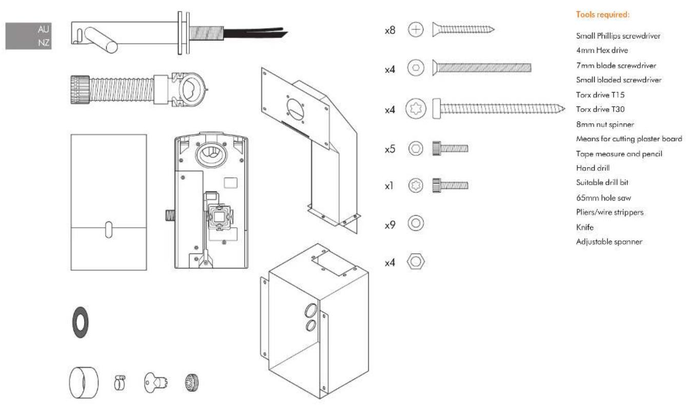
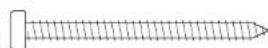
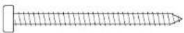
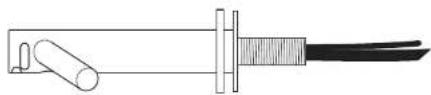
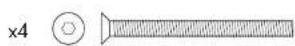
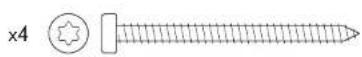
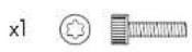
In the box
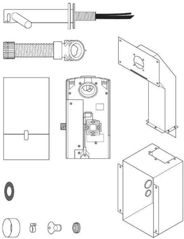
natural_image
Technical line drawings of various electronic components and parts, including a fuse, spring, housing, and mounting bracket (no text or labels present)x8

×4

x4

x5


x1


x9

x4

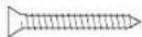
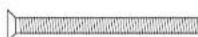
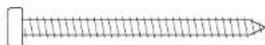
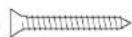
Tools required:
Small Phillips screwdriver
4mm Hex drive
7mm slotted screwdriver
2.5mm slotted screwdriver
Torx T15 screwdriver
Torx drive T30
8mm nut spinner
Means for cutting plaster board
Tape measure and pencil
Hand drill
Suitable drill bit
65mm hole saw
Pliers/wire strippers
Knife
Adjustable spanner
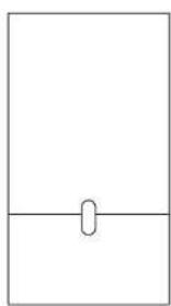
Pre-installation checks
Fig. A
Pre-installation planning
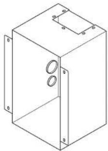
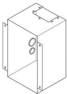
Dyson Airblade Wash+Dry hand dryer is designed so that the motor unit is located behind a stud wall within a metal enclosure which is supplied with the Dyson Airblade Wash + Dry hand dryer Fig. A(i).
The vertical wall studs must be constructed so as to allow the metal enclosure to be fitted between them. Refer to Fig. A(i).
- The unit is designed for a dry, internal location only.
- Consult local and national accessibility codes and regulations for relevant installation guidelines. Conformity and compliance is the responsibility of the installer. Make sure that the unit is installed in compliance with all building codes and/or regulations.
- A means for all-pole disconnection must be incorporated into fixed wiring, in accordance with local wiring regulations.
- Isolate the power and water supplies before installation or service.
- Ensure no pipe work (gas, water, air) or electrical cables, wires or ductwork are located directly behind the drilling/mounting area.
- Dyson recommends the use of protective clothing, eye wear and materials when installing/repairing as necessary.
- This appliance is intended to be permanently connected to the water mains.
Use in food preparation areas
For food preparation environments special installation is required, which must fully enclose the motor bucket and hose in a cleanable housing or have the motor bucket on the reverse side of a wall, provide adequate clearance for cleaning underneath (if applicable) and be such that the unit is at least 2.5 metres from uncovered food or uncovered food-contact surfaces.
Refer to the sink recommendation guide at www.dyson.com prior to install.
- Correct positioning of the: wall studs, wall surface, work surface and basin is essential for a successful installation as shown in Fig. A(ii).
- The key measurement is from the centre of the tap to the floor. The recommended distance is approximately 955mm, but this will differ depending on the height of the sink, refer to Template (Part 2).
- For wall model only: Allow sufficient access space for installation and servicing, see Fig A (ii).
- If a series of units are to be fitted along a wall adjacent to each other, additional planning may be required.
Fig. B
Sink specification guidelines
Using a specially designed test method, Dyson engineers tested a wide range of sinks to assess their compatibility with the Dyson Airblade Wash + Dry hand dryer. For recommended sinks, please use our guide at www.dyson.com.
Porcelain or brushed metal sinks are ideal. Sinks with highly polished surfaces should be avoided e.g. reflective chrome. For minimum sink dimensions refer to Fig. B.
Fig. C/D/E
Tap mounting
There should be a minimum of 100mm and a maximum of 155mm from the top of the sink to the tap centre Fig. C.
There should be a minimum of 290mm between a tap centre and a side wall. When multiple taps are installed side-by-side, tap centres should be a minimum of 580mm apart. This allows sufficient space for mounting the motor bucket, as well as sufficient shoulder room for users Fig. D.
Do not place the downward facing water sensor of the tap over a reflective surface, such as the drainage hole Fig. E.
Fig. F
Soap and locating the soap dispenser
For best user experience, Dyson recommends the use of gel soap.
The infrared sensing zone for air activation extends along each top branch. In order to prevent accidental activation, it's important to consider the user's hand route to the soap dispenser.
The dispenser should be located at least 60mm outside the width of the tap, so the user reaches around the side of the branch.
It should also be located at least 60mm above the branches, so that the sensors are not activated.
Please note that the user may reach diagonally across for the soap, so this path must not go through the sensing zone.
Fig. G/H
Water drainage
Due to high velocity air and water being in close proximity, there is a chance of some water and soap dispersion outside the sink dimensions. To alleviate this effect, we recommend following the guidelines below.
Base Profile
Flat base profile will result in poor drainage leading to high levels of splashback. To improve drainage, avoid sinks with a flat base with particular focus on the immediate area surrounding the drain hole, minimum 60mm radius Fig. G.
Minimum of 6° ramp angle from the edge of the drain hole of the sink will result in good drainage leading to reduced levels of splashback (minimum 60mm radius) Fig. H.
Fig. I/J/K
Base to back and front wall transition
The base to back and front wall transition should also be considered. The back wall should be as close to 90°, and at as sharp a radius as possible Fig. I. Curved geometry is more likely to increase splashback Fig. J, whereas sloping back and front wall transitions should be avoided Fig. K.
Fig. L
Plug hole
Plug holes with the most open aperture are recommended, whereas grill or perforated type plug holes should be avoided as they restrict the drainage of soapy water (lather). Do not use plugs within the plug holes in sinks.
Fig. M
Water temperature control
If you are connecting a hot and cold water feed you will need to install a blender valve.
If connecting to cold only water feed you will need to install a heater.
The water supply to this product must be fitted with a temperature control device in accordance with local regulations.
A= Blender valve
B= Hot and cold feed
C= Desired temperature out
D= Isolation valve
E-Heater
F = Cold feed in
Fig. N
Installing
The main unit must be mounted on a flat vertical wall capable of supporting the full weight of the unit.
One of the horizontal wall studs must be fitted a) so it holds the main weight of the metal duct and the unit, and b) so it is in the correct position for the tap stem.
The unit must be installed using the supplied duct, duct cover and metal enclosure. Do not use sealant when fixing the unit to the wall.
Ensure electricity and mixed water supplies and drainage connections are available for connection. Suitable isolation of the power and water supplies must be in place to switch off supplies before install and for servicing.
Electrical
Input voltage/Frequency: Refer to rating plate.
Isolated by switch fuse spur or RCD as appropriate.
Current 6.6 A
Cable specification: Dual core PVC + Single core PVC (earth)
Local electrical regulations must be adhered to when installing or repairing the product. Rated power: Refer to rating plate.
Operating temperature range: 0^ – 40^ C. Standby power consumption:
Less than 0.5 W.
Maximum altitude: 2,000 metres.
Water operation
Water flow rate: 1.9 l/m standard fitted aerator. 4 l/min with low flow aerator supplied with product.
Water pressure required: 1-8 bar. 1/2" BSP isolated valve required for service.
Keep secondary hot water return as close to blender valve as possible to reduce the risk of Legionella bacteria growth.
Water supply cleanliness and
biological growth
In some countries there are regulations or guidelines that require temperature controlled water supply systems (such as that supplied to the Dyson Airblade Wash+Dry hand dryer) to be subjected to regular cleaning to minimise any biological growth. To enable you to meet these regulations, the Dyson Airblade Wash+Dry hand dryer has been designed and tested to withstand internal cleaning both with hot water up to 95°C and with sodium hypochlorite at a concentration of 0.45%.
Please refer to specific (market) regulations and water supply system recommendations for information on cleaning regimes for water supply cleanliness and biological growth for your country.
When carrying out internal cleaning of the Dyson Airblade Wash + Dry hand dryer, please be aware of any safety considerations when using hot water or chemicals. Dyson will not be responsible for any injury caused by this process.
Abusive testing
The Dyson Airblade Wash + Dry hand dryer has undergone rigorous abusive testing to ensure that it can withstand substantial forces and impacts typical of a commercial and public bathroom environment.
Step-by-step
Fig. 1/2
Assemble enclosure
Assemble the metal enclosure and ducting as shown in Fig. 1 using the 5 x hex head bolts and washers supplied.
Construct the wall studding ensuring
adequate space to fit the metal enclosure and ducting as shown in Fig. 2.
The key measurement is from the centre of the tap to the floor. The recommended distance is approximately 955mm but this will differ depending on the height of the sink, refer to Template (Part 2).
Fig. 3
Enclosure mounting
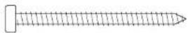
Fit the enclosure and ducting into the wall studs and mark the location of the 8× screw holes on the wall studs using the fixing holes in the enclosure and ducting as a guide. Ensure that the enclosure is pushed up again the top horizontal stud to set correct tap height and that it is level Fig. 3.
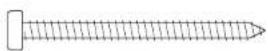
Remove the enclosure and ducting and drill 8 x fixing holes using a suitable drill bit for the 8 x M5 wood screws Fig. 3.
CAUTION: Do not use the enclosure and ducting as a guide when drilling.
Fix the enclosure and ducting into the wall studs and fix using the 8 x countersunk screws provided Fig. 3.
Fig. 4
Installation of power and water supply and earth
WARNING: Risk of electric shock!
Ensure that the power supply is switched off before continuing.
NOTE: The enclosure must be earthed. Pierce a small hole in the lower grommet and feed through the electrical supply as shown. Use suitable conduit and electrical fittings.
Pierce a small hole in the upper grommet and feed through the mixed water supply as shown. Flexible conduit with a 12 " BSP connection should be used.
Connect earth cable to one of the M5 studs in the top of the enclosure following local electrical guidelines/regulation
A=Water
B= Electric
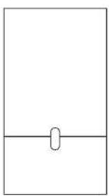
Fig. 5
Installing plasterboard
Measure the position of the tap mounting hole from a suitable horizontal and vertical reference as shown.
Mark the center of the tap mounting hole on the plasterboard using the measured dimensions.
Use this mark to position the template on the plaster board and cut and drill holes for the top stem, the stem fixing holes, the access hole and access panel fixing holes as detailed on the Template (Part 2).
Line up the holes in the plasterboard with the holes in the enclosure and ducting and attach the plasterboard to the wall studding using appropriate fixings.
Fit sink and work surface as required.
Finish the wall surface as required.
Clean and remove any dust or debris from the inside of the enclosure.
Fig. 6
Preparing for installation of backplate Remove the motor bucket from the backplate by pressing the red release catch at the bottom and lifting up as shown in Fig. 6a.
Store the motor bucket safely until required. Remove the water pipe cover and the electrics cover from the backplate as shown in Fig. 6b and 6c. Store them safely along with fixings until required.
Fig. 7
Backplate installation planning
Fix the backplate onto the metal studs inside the enclosure and secure with the 4 x M5 nuts and washers supplied as shown in Fig. 7.
Fig. 8
Hose installation
Unscrew the cover plate from the tap stem. Slide the rubber seal over the water tube and sensor cable and onto the tap stem as shown in Fig. 8a.
Slide the grey hose up over the water tube and sensor cable Fig. 8b.
Feed the water tube through the left exit hole in the hose duct as shown in Fig. 8c.
Use pliers to gently pull the water tube through as far as the solid white line Fig. 8d. Ensure the grommet on the water tube fits tightly into the hose duct so that it is airtight Fig. 8e.
Feed the sensor cable through the right exit hole as shown in Fig. 8c. DO NOT use pliers as this may damage the electrical connections Fig. 8d. Ensure the grommet on the cable fits tightly into the hose duct so that it is airtight Fig. 8e.
Screw the upper hose collar onto the tap stem so that it is hand tight Fig. 8f.
A= Rubber seal
B= Water tube
C= Sensor cable
D = Grey hose
Fig. 9
Secure tap
Feed the hose through the hole in the plasterboard and into the metal duct.
The rubber seal should now fit between the tap stem and the wall Fig. 9a.
Fix the tap to the plasterboard wall, lining up the mounting holes and making sure that the tap sits flat on the rubber seal and wall Fig. 9b.
Attach the tap to the ducting behind the plasterboard using the 4 x M5 CSK screws supplied as shown in Fig. 9b making sure that the tap is level before fully tightening.
Screw the cover plate over the tap mounting plate and tighten to hand tight Fig. 9c.
A= Rubber seal
B = Grey hose
C = Tap stem
D= Cover plate
Fig. 10
Connecting the tap
Clip the grey hose into the backplate.
Plug the sensor cable in the hose into the connector in the backplate as shown in Fig. 10. Check the orientation of the connector; the two tabs must be lined up. Ensure the cable is correctly routed in the backplate.
Fig. 11
Connecting the water tube
Cut the water tube to size at the dotted white line as shown in Fig. 11a.
Slide the hose clip (supplied) onto the water tube Fig. 11b.
Remove the 2 x Phillips screws and unclip the solenoid from the backplate Fig. 11b.
Attach the water hose to the solenoid Fig. 11c.
Clip the solenoid back on to the backplate and fasten the 2 x screws Fig. 11d.
Tighten the hose clip and ensure the solenoid cable is correctly positioned in the retaining channel.
Fig. 12
Connecting the electricity supply
Route the electricity supply to the backplate using approved flexible or solid conduit and fittings. Ensure the power cable is long enough to connect to the terminal block mounted in the back plate.
Route the cable into the backplate and tighten the cable gland.
Strip the cable to a suitable length and secure the live and neutral wires into the corresponding terminal blocks as shown in Fig. 12. Ensure the correct positioning of the cables before proceeding.
Fig. 13
Re-assemble electrical cover
Fix the electrics cover and secure with the 6 x fixings supplied ensuring no wires are trapped.
Fig. 14
Connecting the mixed water supply
NOTE: Ensure water feed has been completely flushed of debris, copper filings etc. prior to connecting to the backplate. Failure to do so may damage the solenoid valve.
Connect the isolated, mixed water supply to the backplate.
Turn on the water.
Inspect for leaks at the main water supply inlet and the water tube connection to the tap.
Also check for leaks at the solenoid connection.
Fig. 15
Switching power on
Switch on power to the machine.
CALIBRATION CYCLE: Once installed, the tap will go through a 30 second calibration cycle.
Place hand under sensor on tap to activate water flow.
Check for leaks as per Fig. 14.
Secure the water pipe cover on to the backplate using the 2 x fixings provided.
Fig. 16
Assembling the motor bucket
Hook the motor to the top of the electrics cover. Swing it downwards so it clicks into place as shown. Push in securely.
OPTIONAL: A screw is supplied to secure the red release button and prevent unwanted removal of the motor bucket.
Test the unit for correct operation.
Fig. 17
Fitting the access panel
Fix the access panel to the plasterboard using the 4 x M6 screws.
installation
Test the hand dryer for normal operation:
- Place your hands beneath the centre of the tap and water will flow automatically for as long as the hands remain in place.
- Place your hands to either side of the centre tap to activate the hand dryer, creating sheets of air to scrape water from your hands.
- Move your hands backwards and forwards slowly through the air, turning them over so both back and front are exposed to the airflow.
Automatic duty flush
The unit is equipped with a fixed automatic water flush, which activates for 60 seconds 24 hours after last use. This helps reduce water stagnation and bacteria proliferation within the product.
Please ensure that the unit is always installed over a functional basin with free and connected drainage.
TroubleshootingTest
Hand dryer fails to start:
- Check fuse/circuit breaker is working and that the power and water supply are connected.
- Ensure the cleaning cap is removed and that the sensors are clean and unobstructed.
– Turn the unit off and on.
Hand dryer turns itself on and off erratically:
– Tum the unit off and on.
- Ensure there is no plug in the sink and remove if plug is present.
– Ensure sensors are clean.
- Check that the sensor cable from the tap is securely connected.
Hand dryer sometimes cuts out in use:
– Turn the unit off and on.
– Ensure sensors are clean.
- Check the air inlets are clean and free of dust. If the air inlets are dusty simply remove dust.
– Ensure that the air inlets are free from obstructions and have sufficient clearance.
The dry time has increased:
- Inspect the air inlets for dust and remove.
– Inspect filter and change if required. - Ensure that the hose is securely attached to the base of the tap and no leaks are present.
The airflow is running hotter than usual:
– Inspect the air inlets for dust and remove.
– Inspect filter and change if required.
- Ensure that the hose is securely attached to the base of the tap and no leaks are present.
Air is continuously running:
- Check for any object in the sink and remove if necessary.
- Ensure sensors are clean and free from any obstructions.
– Inspect filter and change if required.
- Ensure that the hose is securely attached to the base of the tap and no leaks are present.
There is no air running:
– Turn the unit off and on.
- Check fuse/circuit breaker is working and that the power is connected.
– Ensure sensors are clean.
- Ensure that the air hose is securely attached to the base of the tap and no leaks are present.
- Check that the sensor cable from the top is securely connected.
Water is continuously coming from the tap:
- Ensure sensors are clean and free from any obstructions.
There is no water coming from the tap:
- Ensure that the power and water supplies are turned on and that the isolation valve is open.
- Ensure that the aerator is free from debris, remove and clean/replace if necessary.
The water coming from the tap is overly hot or cold:
- Check the blender valve is set to the desired temperature.
Contact Dyson Customer Care for further support and information or online at www.dyson.com
AU/NZ
Contents
AU NZ
Important Safety Instructions 13
In the box 14
Pre-installation checks 15
Installation
Step-by-step 17
Test installation 19
Troubleshooting 19
IMPORTANT SAFETY INSTRUCTIONS
READ AND SAVE THESE INSTRUCTIONS
BEFORE INSTALLING OR USING THIS UNIT READ ALL INSTRUCTIONS AND CAUTIONARY MARKINGS IN THIS INSTALLATION GUIDE AND THE OWNERS MANUAL.
WARNING
ALL INSTALLATION AND REPAIR WORK (PLUMBING AND ELECTRICAL) SHOULD BE CARRIED OUT BY A QUALIFIED PERSON OR DYSON SERVICE ENGINEER IN ACCORDANCE WITH CURRENT LOCAL CODES OR REGULATIONS.
WARNING
RISK OF ELECTRIC SHOCK!
IF CASING IS REMOVED OR HANDLED IMPROPERLY THE INTERNAL COMPONENTS OF THE UNIT MAY CAUSE HARM OR BECOME PERMANENTLY DAMAGED.
THIS UNIT MUST BE EARTHED TO REDUCE THE RISK OF FIRE, ELECTRIC SHOCK, OR INJURY TO PERSONS, OBSERVE THE FOLLOWING:
Before beginning any installation work you must confirm the following.
- Check that the electrical supply corresponds to that shown on the rating plate.
- A means for all-pole disconnection must be incorporated into fixed wiring, in accordance with local wiring regulations.
- Connect the electricity supply using suitable conduit and electrical fittings. Ensure that the conduit and wires are long enough to connect to the backplate and the terminal block. Solid metal conduit is not suitable for side entry.
WARNING
Use caution when unpacking the components. There may be sharp edges/corners which may cut or cause harm.
DO NOT USE ANY JET WASH EQUIPMENT FOR CLEANING ON OR NEAR THIS UNIT
In the box
x8
×4
x4
x5
x1
x9
×4
Tools required:
Small Phillips screwdriver
4mm Hex drive
7mm blade screwdriver
Small bladed screwdriver
Torx drive T15
Torx drive T30
8mm nut spinner
Means for cutting plaster board
Tape measure and pencil
Hand drill
Suitable drill bit
65mm hole saw
Pliers/wire strippers
Knife
Adjustable spanner
Pre-installation checks
Fig. A
Pre-installation planning
The Dyson Airblade Wash+Dry hand dryer is designed so that the motor unit is located behind a stud wall within a metal enclosure which is supplied with the Dyson Airblade Wash+Dry. Fig. A(1)
The vertical wall studs must be constructed so as to allow the metal enclosure to be fitted between them. Refer to Fig. A(i).
-The unit is designed for dry, internal location only.
- Consult local and national accessibility codes and regulations for relevant installation guidelines. Conformity and compliance is the responsibility of the installer. Make sure that the unit is installed in compliance with all building codes and/or regulations.
-A means for all-pole disconnection must be incorporated into fixed wiring, in accordance with local wiring regulations -Isolate the power and water supplies before installation or service.
- Ensure no pipe work (gas, water, air) or electrical cables, wires or ductwork are located directly behind the drilling/mounting area.
-Dyson recommends the use of protective clothing, eyeware and materials when installing/repairing as necessary.
—This appliance is intended to be permanently connected to the water mains.
Use in food preparation areas
For food preparation environments special installation is required, which must fully enclose the motor bucket and hose in a cleanable housing or have the motor bucket on the reverse side of a wall, provide adequate clearance for cleaning underneath (if applicable) and be such that the unit is at least 2.5 metres from uncovered food or uncovered food-contact surfaces.
Refer to the Sink recommendation guide at www.dyson.com prior to install.
- Correct positioning of the: wall studs, wall surface, work surface and basin is essential for a successful installation as shown in
Fig. A(ii).
-The key measurement is from the center of the tap to the floor. The recommended distance is approximately 955mm , but this will differ depending on the height of the sink, refer to Template (Part 2).
-Allow sufficient access space for installation and servicing.
-If a series of units are to be fitted along a wall adjacent to each other, additional planning may be required.
Fig. B
Sink specification guidelines
Using a specially designed test method, Dyson engineers tested a wide range of sinks to assess their compatibility with the Dyson Airblade Wash+Dry hand dryer. For recommended sinks, please use our guide at www.dyson.com.au.
Porcelain or brushed metal sinks are ideal. Sinks with highly polished surfaces should be avoided e.g. reflective chrome.
For minimum sink dimensions refer to Fig. B.
Fig. C/D/E
Tap mounting
There should be a minimum of 100mm and a maximum of 155mm from the top of the sink to the tap centre. Fig. C
There should be a minimum of 290mm between a tap centre and a side wall. When multiple taps are installed side-byside, tap centres should be a minimum of 580mm apart. This allows sufficient space for mounting the motor bucket, as well as sufficient shoulder room for users. Fig. D
Do not place the downward facing water sensor of the top over a reflective surface, such as the drainage hole. Fig. E
Fig. F
Soap and locating the soap dispenser
For best user experience, Dyson recommends the use of gel soap.
The infrared sensing zone for air activation extends along each tap branch. In order to prevent accidental activation, it's important to consider the user's hand route to the soap dispenser.
The dispenser should be located at least 60mm outside the width of the tap, so the user reaches around the side of the branch.
It should also be located at least 60mm above the branches, so that the sensors are not activated.
Please note that the user may reach diagonally across for the soap, so this path must not go through the sensing zone.
Fig. G/H
Water drainage
Due to high velocity air and water being in close proximity, there is a chance of some water and soap dispersion outside the sink dimensions. To alleviate this effect, we recommend following the guidelines below.
Base Profile
Flat base profile will result in poor drainage leading to high levels of splashback. To improve drainage, avoid sinks with a flat base with particular focus on the immediate area surrounding the drain hole, minimum 60mm radius. Fig. G.
Minimum of 6° ramp angle from the edge of the drain hole of the sink will result in good drainage leading to reduced levels of splashback (minimum 60mm radius). Fig. H
Fig. I/J/K
Base to back and front wall transition
The base to back and front wall transition should also be considered. The back wall should be as close to 90°, and at as sharp a radius as possible Fig. I. Curved geometry is more likely to increase splashback Fig. J, whereas sloping back and front wall transitions should be avoided Fig. K.
Fig. L
Plug hole
Plug holes with the most open aperture are recommended, whereas grill or perforated type plug holes should be avoided as they restrict the drainage of soapy water (lather). Do not use plugs within the plug holes in sinks.
Fig. M
Water temperature control
If you are connecting a hot and cold water feed you will need to install a thermostatic mixing valve.
If connecting to cold only water feed you will need to install a heater.
The water supply to this product must be fitted with a temperature control device in accordance with local regulations.
A= Thermostatic mixing valve
B= Hot and cold feed
C= Desired temperature out
D= Isolation valve
E-Heater
F = Cold feed in
Fig. N
Installing
The main unit must be mounted on a flat vertical wall capable of supporting the full weight of the unit.
One of the horizontal wall studs must be fitted a) so it holds the main weight of the metal duct and the unit, and b) so it is in the correct position for the tap stem.
The unit must be installed using the supplied duct, duct cover and metal enclosure. Do not use sealant when fixing the unit to the wall.
Ensure electricity and mixed water supplies and drainage connections are available for connection. Suitable isolation of the power and water supplies must be in place to switch off supplies before install and for servicing.
Electrical
Input voltage/Frequency: Refer to rating plate. Isolated by switch fuse spur or RCD as appropriate.
Current 6.6 A.
Cable specification: Dual core PVC + Single core PVC (earth)
Local electrical regulations must be adhered to when installing or repairing the product. Rated power: Refer to rating plate.
Operating temperature range: 0^-40^ . Standby power consumption: Less than 0.5 W.
Maximum altitude: 2,000 metres.
Water operation
Water flow rate: 4 l/min normal fitted aerator. 1.9 l/m with low flow aerator supplied with product.
Water pressure required: 1-8 bar. 1/2" BSP isolated valve required for service.
Keep secondary hot water return as close to thermostatic mixing valve as possible to reduce the risk of Legionella bacteria growth.
Water supply cleanliness and biological growth
In some countries there are regulations or guidelines that require temperature controlled water supply systems (such as that supplied to the Dyson Airblade Wash+Dry hand dryer) to be subjected to regular cleaning to minimise any biological growth. To enable you to meet these regulations, the Dyson Airblade Wash+Dry hand dryer has been designed and tested to withstand internal cleaning both with hot water up to 95°C and with sodium hypochlorite at a concentration of 0.45%.
Please refer to specific (market) regulations and water supply system recommendations for information on cleaning regimes for water supply cleanliness and biological growth for your country.
When carrying out internal cleaning of the Dyson Airblade Wash+Dry hand dryer, please be aware of any safety considerations when using hot water or chemicals. Dyson will not be responsible for any injury caused by this process.
Abusive testing
The Dyson Airblade Wash + Dry hand dryer has undergone rigorous abusive testing to ensure that it can withstand substantial forces and impacts typical of a commercial and public bathroom environment.
Step-by-step
Fig. 1/2
Assemble enclosure
Assemble the metal enclosure and ducting as shown in Fig. 1 using the 5 x hex head bolts and washers supplied.
Construct the wall studding ensuring
adequate space to fit the metal enclosure and ducting as shown in Fig. 2.
The key measurement is from the centre of the tap to the floor. The recommended distance is approximately 955mm but this will differ depending on the height of the sink, refer to Template (Part 2).
Fig. 3
Enclosure mounting
Fit the enclosure and ducting into the wall studs and mark the location of the 8× screw holes on the wall studs using the fixing holes in the enclosure and ducting as a guide. Ensure that the enclosure is pushed up again the top horizontal stud to set correct tap height and that it is level Fig. 3.
Remove the enclosure and ducting and drill 8 x fixing holes using a suitable drill bit for the 8 x M5 wood screws Fig. 3.
CAUTION: Do not use the enclosure and ducting as a guide when drilling.
Fix the enclosure and ducting into the wall studs and fix using the 8 x countersunk screws provided Fig. 3.
Fig. 4
Installation of power and water supply and earth
WARNING: Risk of electric shock!
Ensure that the power supply is switched off before continuing.
NOTE: The enclosure must be earthed. Pierce a small hole in the lower grommet and feed through the electrical supply as shown. Use suitable conduit and electrical fittings.
Pierce a small hole in the upper grommet and feed through the mixed water supply as shown. Flexible conduit with a 12 " BSP connection should be used.
Connect earth cable to one of the M5 studs in the top of the enclosure following local electrical guidelines/regulation
A=Water
B= Electric
Fig. 5
Installing plasterboard
Measure the position of the tap mounting hole from a suitable horizontal and vertical reference as shown.
Mark the center of the tap mounting hole on the plasterboard using the measured dimensions.
Use this mark to position the template on the plaster board and cut and drill holes for the top stem, the stem fixing holes, the access hole and access panel fixing holes as detailed on the Template (Part 2).
Line up the holes in the plasterboard with the holes in the enclosure and ducting and attach the plasterboard to the wall studding using appropriate fixings.
Fit sink and work surface as required.
Finish the wall surface as required.
Clean and remove any dust or debris from the inside of the enclosure.
Fig. 6
Preparing for installation of backplate Remove the motor bucket from the backplate by pressing the red release catch at the bottom and lifting up as shown in Fig. 6a.
Store the motor bucket safely until required. Remove the water pipe cover and the electrics cover from the backplate as shown in Fig. 6b and 6c. Store them safely along with fixings until required.
Fig. 7
Backplate installation
Fix the backplate onto the metal studs inside the enclosure and secure with the 4 x M5 nuts and washers supplied as shown in Fig. 7.
Fig. 8
Hose Installation
Unscrew the cover plate from the tap stem. Slide the rubber seal over the water tube and sensor cable and onto the tap stem as shown in Fig. 8a.
Slide the grey hose up over the water tube and sensor cable Fig. 8b.
Feed the water tube through the left exit hole in the hose duct as shown in Fig. 8c.
Use pliers to gently pull the water tube through as far as the solid white line Fig. 8d. Ensure the grommet on the water tube fits tightly into the hose duct so that it is airtight Fig. 8e.
Feed the sensor cable through the right exit hole as shown in Fig. 8c. DO NOT use pliers as this may damage the electrical connections Fig. 8d. Ensure the grommet on the cable fits tightly into the hose duct so that it is airtight Fig. 8e.
Screw the upper hose collar onto the tap stem so that it is hand tight Fig. 8f.
A= Rubber seal
B= Water tube
C= Sensor cable
D = Grey hose
Fig. 9
Secure tap
Feed the hose through the hole in the plasterboard and into the metal duct.
The rubber seal should now fit between the tap stem and the wall Fig. 9a.
Fix the tap to the plasterboard wall, lining up the mounting holes and making sure that the tap sits flat on the rubber seal and wall Fig. 9b.
Attach the tap to the ducting behind the plasterboard using the 4 x M5 CSK screws supplied as shown in Fig. 9b making sure that the tap is level before fully tightening.
Screw the cover plate over the tap mounting plate and tighten to hand tight Fig. 9c.
A= Rubber seal
B = Grey hose
C = Tap stem
D= Cover plate
Fig. 10
Connecting the tap
Clip the grey hose into the backplate.
Plug the sensor cable in the hose into the connector in the backplate as shown in Fig. 10. Check the orientation of the connector; the two tabs must be lined up. Ensure the cable is correctly routed in the backplate.
Fig. 11
Connecting the water tube
Cut the water tube to size at the dotted white line as shown in Fig. 11a.
Slide the hose clip (supplied) onto the water tube Fig. 11b.
Remove the 2 x Phillips screws and unclip the solenoid from the backplate Fig. 11b.
Attach the water hose to the solenoid Fig. 11c.
Clip the solenoid back on to the backplate and fasten the 2 x screws Fig. 11d.
Tighten the hose clip and ensure the solenoid cable is correctly positioned in the retaining channel.
Fig. 12
Connecting the electricity supply
Route the electricity supply to the backplate using approved flexible or solid conduit and fittings. Ensure the power cable is long enough to connect to the terminal block mounted in the back plate.
Route the cable into the backplate and tighten the cable gland.
Strip the cable to a suitable length and secure the live and neutral wires into the corresponding terminal blocks as shown in
Fig. 12. Ensure the correct positioning of the cables before proceeding.
Fig. 13
Re-assemble electrical cover
Fix the electrics cover and secure with the 6 x fixings supplied ensuring no wires are trapped.
Fig. 14
Connecting the mixed water supply
NOTE: ensure water feed has been completely flushed of debris, copper filings etc. prior to connecting to the backplate. Failure to do so may damage the solenoid valve resulting in it not closing properly, creating a a dripping tap.
Connect the isolated, mixed water supply to the backplate.
Turn on the water.
Inspect for leaks at the main water supply inlet and the water tube connection to the tap. Also check for leaks at the solenoid connection.
Fig. 15
Switching power on
Switch on power to the machine.
CALIBRATION CYCLE: Once installed, the tap will go through a 30 second calibration cycle.
Place hand under sensor on tap to activate water flow.
Check for leaks as per Fig. 14.
Secure the water pipe cover onto the backplate using the 2 x fixings provided.
Fig. 16
Assembling the motor bucket
Hook the motor to the top of the electrics cover. Swing it downwards so it clicks into place as shown. Push in securely.
OPTIONAL: A screw is supplied to secure the red release button and prevent unwanted removal of the motor bucket.
Test the unit for correct operation.
Fig. 17
Fitting the access panel
Fix the access panel to the plasterboard using the 4 x M6 screws.
installation
Test the hand dryer for normal operation:
—Place your hands beneath the centre of the tap and water will flow automatically for as long as the hands remain in place.
—Place your hands to either side of the centre tap to activate the hand dryer, creating sheets of air to scrape water from your hands.
-Move your hands backwards and forwards slowly through the air, turning them over so both back and front are exposed to the airflow.
Automatic duty flush
The unit is equipped with a fixed automatic water flush, which activates for 60 seconds 24 hours after last use. This helps reduce water stagnation and bacteria proliferation within the product.
Please ensure the unit is always installed over a functional basin with free and connected drainage.
TroubleshootingTest
Hand dryer fails to start:
-Check fuse/circuit breaker is working and that the power and water supply are connected.
—Ensure the cleaning cap is removed and that the sensors are clean and unobstructed.
-Turn the unit off and on.
Hand dryer turns itself on and off erratically:
-Turn the unit off and on.
- Ensure there is no plug in the sink and remove if plug is present.
—Ensure sensors are clean.
-Check that the sensor cable from the tap is securely connected.
Hand dryer sometimes cuts out in use:
-Turn the unit off and on.
-Ensure sensors are clean.
- Check the air inlets are clean and free of dust. If the air inlets are dusty simply remove dust.
- Ensure that the air inlets are free from obstructions and have sufficient clearance.
The dry time has increased:
-Inspect the air inlets for dust and remove.
-Inspect filter and change if required.
—Ensure that the hose is securely attached to the base of the tap and no leaks are present.
The airflow is running hotter than usual:
-Inspect the air inlets for dust and remove.
-Inspect filter and change if required.
—Ensure that the hose is securely attached to
the base of the tap and no leaks are present.
Air is continuously running:
- Check for any object in the sink and remove if necessary.
-Ensure sensors are clean and free from any obstructions.
-Inspect filter and change if required.
-Ensure that the hose is securely attached to
the base of the tap and no leaks are present.
There is no air running:
—Turn the unit off and on.
- Check fuse/circuit breaker is working and that the power is connected.
—Ensure sensors are clean.
- Ensure that the air hose is securely attached to the base of the tap and no leaks are present.
-Check that the sensor cable from the tap is securely connected.
Water is continuously coming from the tap:
- Ensure sensors are clean and free from any obstructions.
There is no water coming from the tap:
—Ensure that the power and water supplies
are turned on and that the isolation valve is open.
- Ensure that the aerator is free from debris, remove and clean/replace if necessary.
The water coming from the tap is overly hot or cold:
- Check the thermostatic mixing valve is set to the desired temperature.
Contact Dyson Customer Care for further support and information:
Australia Contact: 1800 426 337 or
aucustomercare@dyson.com.
www.dyson.com.au
New Zealand contact: 0800 397 667
www.dyson.co.nz
BG
Съдържание
BG
natural_image
Exploded view diagram of an electrical enclosure showing internal components and exploded views (no text or labels)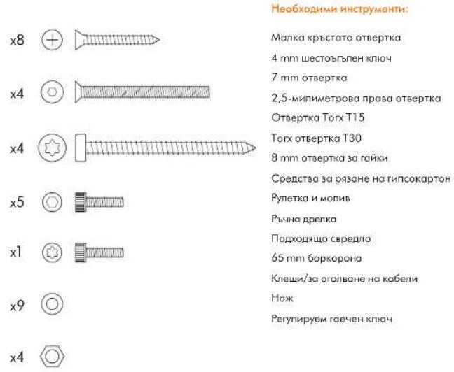
natural_image
Pure electrical circuit lines without any symbols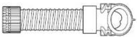
natural_image
Simple line drawing of a rectangular shape with a horizontal line and a small oval cutout at the center (no text or symbols)
natural_image
Technical line drawing of a mechanical device interior (no text or symbols)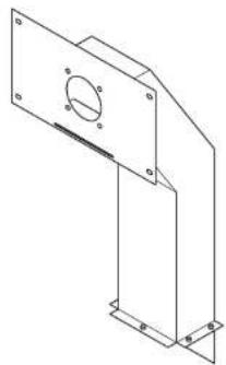
natural_image
Technical line drawing of a mechanical bracket with mounting holes and a central circular feature (no text or symbols)


natural_image
Isometric line drawing of a rectangular box with two circular cutouts and mounting holes (no text or symbols)x8


x4


x4


x5


x1


x9

x4

Important Safety Instructions 37
In the box 38
Pre-installation checks 39
Installation
Step-by-step 41
Test installation 43
Troubleshooting 43
IMPORTANT SAFETY INSTRUCTIONS
READ AND SAVE THESE INSTRUCTIONS
BEFORE INSTALLING OR USING THIS UNIT READ ALL INSTRUCTIONS AND CAUTIONARY MARKINGS IN THIS INSTALLATION GUIDE AND THE OWNERS MANUAL.
WARNING
ALL INSTALLATION AND REPAIR WORK (PLUMBING AND ELECTRICAL) SHOULD BE CARRIED OUT BY A QUALIFIED PERSON OR DYSON SERVICE ENGINEER IN ACCORDANCE WITH CURRENT LOCAL CODES OR REGULATIONS.
WARNING
RISK OF ELECTRIC SHOCK!
IF CASING IS REMOVED OR HANDLED IMPROPERLY THE INTERNAL COMPONENTS OF THE UNIT MAY CAUSE HARM OR BECOME PERMANENTLY DAMAGED.
THIS METAL ENCLOSURE MUST BE GROUNDED TO REDUCE THE RISK OF FIRE, ELECTRIC SHOCK, OR INJURY TO PERSONS, OBSERVE THE FOLLOWING:
Before beginning any installation work you must confirm the following.
- Check that the electrical supply corresponds to that shown on the rating plate.
- A means for all-pole disconnection must be incorporated into fixed wiring, in accordance with local wiring regulations.
- Connect the electricity supply using suitable conduit and electrical fittings. Ensure that the conduit and wires are long enough to connect to the backplate and the terminal block. Solid metal conduit is not suitable for side entry.
WARNING
Use caution when unpacking the components. There may be sharp edges/corners which may cut or cause harm.
DO NOT USE ANY JET WASH EQUIPMENT FOR CLEANING ON OR NEAR THIS UNIT

In the box
x8


×4


x4


x5


x1


x9

x4

Tools required:
Small Phillips screwdriver
4mm Hex drive
7mm blade screwdriver
Small bladed screwdriver
Torx drive T15
Torx drive T30
8mm nut spinner
Means for cutting plaster board
Tape measure and pencil
Hand drill
Suitable drill bit
65mm hole saw
Pliers/wire strippers
Knife
Adjustable spanner
Pre-installation checks
Fig. A
Pre-installation planning
The Dyson Airblade Wash+Dry hand dryer is designed so that the motor unit is located behind a stud wall within a metal enclosure which is supplied with the Dyson Airblade Wash+Dry. Fig. A(1)
The vertical wall studs must be constructed so as to allow the metal enclosure to be fitted between them. Refer to Fig. A(i).
- The unit is designed for dry, internal location only.
- Consult local and national accessibility codes and regulations for relevant installation guidelines. Conformity and compliance is the responsibility of the installer. Make sure that the unit is installed in compliance with all building codes and/or regulations.
-A means for all-pole disconnection must be incorporated into fixed wiring, in accordance with local wiring regulations. -Isolate the power and water supplies before installation or service.
- Ensure no pipe work (gas, water, air) or electrical cables, wires or ductwork are located directly behind the drilling/mounting area.
-Dyson recommends the use of protective clothing, eye wear and materials when installing/repairing as necessary.
- This appliance is intended to be permanently connected to the water mains.
Use in food preparation areas
For food preparation environments special installation is required, which must fully enclose the motor bucket and hose in a cleanable housing or have the motor bucket on the reverse side of a wall, provide adequate clearance for cleaning underneath (if applicable) and be such that the unit is at least 2.5 metres (8.20 feet) from uncovered food or uncovered food-contact surfaces.
Refer to the Sink recommendation guide at www.dysoncanada.ca prior to install.
- Correct positioning of the: wall studs, wall surface, work surface and basin is essential for a successful installation as shown in
Fig. A(ii).
-The key measurement is from the center of the tap to the floor. The recommended distance is approximately 955mm (37.59 inches), but this will differ depending on the height of the sink, refer to Template (Part 2). -Allow sufficient access space for installation and servicing.
-If a series of units are to be fitted along a wall adjacent to each other, additional planning may be required.
Fig. B
Sink specification guidelines
Using a specially designed test method, Dyson engineers tested a wide range of sinks to assess their compatibility with the Dyson Airblade Wash+Dry hand dryer. For recommended sinks, please use our guide at www.dysoncanada.ca.
Porcelain or brushed metal sinks are ideal. Sinks with highly polished surfaces should be avoided e.g. reflective chrome. For minimum sink dimensions refer to Fig. B.
Fig. C/D/E
Tap mounting
There should be a minimum of 100mm (3.93 inches) and a maximum of 155mm (6.10 inches) from the top of the sink to the tap centre. Fig. C.
There should be a minimum of 290mm (11.41 inches) between a tap centre and a side wall. When multiple taps are installed side-byside, tap centres should be a minimum of 580mm (22.83 inches) apart. This allows sufficient space for mounting the motor bucket, as well as sufficient shoulder room for users. Fig. D.
Do not place the downward facing water sensor of the top over a reflective surface, such as the drainage hole. Fig. E.
Fig. F
Soap and locating the soap dispenser
For best user experience, Dyson recommends the use of gel soap.
The infrared sensing zone for air activation extends along each tap branch. In order to prevent accidental activation, it's important to consider the user's hand route to the soap dispenser.
The dispenser should be located at least 60mm (2.36 inches) outside the width of the top, so the user reaches around the side of the branch.
It should also be located at least 60mm (2.36 inches) above the branches, so that the sensors are not activated.
Please note that the user may reach diagonally across for the soap, so this path must not go through the sensing zone.
Fig. G/H
Water drainage
Due to high velocity air and water being in close proximity, there is a chance of some water and soap dispersion outside the sink dimensions. To alleviate this effect, we recommend following the guidelines below.
Base Profile
Flat base profile will result in poor drainage leading to high levels of splashback. To improve drainage, avoid sinks with a flat base with particular focus on the immediate area surrounding the drain hole, minimum 60mm (2.36 inches) radius. Fig. G.
Minimum of 6° ramp angle from the edge of the drain hole of the sink will result in good drainage leading to reduced levels of splashback (minimum 60mm (2.36 inches) radius). Fig. H.
Fig. I/J/K
Base to back and front wall transition The base to back and front wall transition should also be considered. The back wall should be as close to 90°, and at as sharp a radius as possible Fig. L. Curved geometry is more likely to increase splashback
Fig. J, whereas sloping back and front wall transitions should be avoided Fig. K.

Fig. L
Plug hole
Plug holes with the most open aperture are recommended, whereas grille or perforated type plug holes should be avoided as they restrict the drainage of soapy water (lather). Do not use plugs within the plug holes in sinks.
Fig. M
Water temperature control
If you are connecting a hot and cold water feed you will need to install a blender valve.
If connecting to cold only water feed you will need to install a heater.
The water supply to this product must be fitted with a temperature control device in accordance with local regulations.
A= Blender valve
B= Hot and cold feed
C= Desired temperature out
D= Isolation valve
E= Hecter
F = Cold feed in
Fig. N
Installing
The main unit must be mounted on a flat vertical wall capable of supporting the full weight of the unit.
One of the horizontal wall studs must be fitted a) so it holds the main weight of the metal duct and the unit, and b) so it is in the correct position for the tap stem.
The unit must be installed using the supplied duct, duct cover and metal enclosure.
Do not use sealant when fixing the unit to the wall.
Ensure electricity and mixed water supplies and drainage connections are available for connection. Suitable isolation of the power and water supplies must be in place to switch off supplies before install and for servicing.
Electrical
Input voltage/Frequency: Refer to rating plate. Isolated by switch fuse spur or RCD
as appropriate.
Current 6.6 A.
Local electrical regulations must be adhered to when installing or repairing the product.
Rated power: Refer to rating plate.
Operating temperature range: 0°C – 40°C.
Standby power consumption:
Less than 0.5 W.
Maximum altitude: 2,000 metres.
Water operation
Water flow rate: 4 l/min normal fitted aerator.
1.9 l/m with low flow aerator supplied with product.
Water pressure required: 1-8 bar. 3.8 cm
(1.5 inches) BSP isolated valve required
for service.
Keep secondary hot water return as close to blender valve as possible to reduce the risk of Legionella bacteria growth.
Water supply cleanliness and
biological growth
In some countries there are regulations or guidelines that require temperature controlled water supply systems (such as that supplied to the Dyson Airblade Wash + Dry hand dryer) to be subjected to regular cleaning to minimise any biological growth. To enable you to meet these regulations, the Dyson Airblade Wash + Dry hand dryer has been designed and tested to withstand internal cleaning both with hot water up to 95°C and with sodium hypochlorite at a concentration of 0.45%.
Please refer to specific (market) regulations and water supply system recommendations for information on cleaning regimes for water supply cleanliness and biological growth for your country.
When carrying out internal cleaning of the Dyson Airblade Wash+Dry hand dryer, please be aware of any safety considerations when using hot water or chemicals. Dyson Canada will not be responsible for any injury caused by this process.
Abusive testing
The Dyson Airblade Wash+Dry hand dryer has undergone rigorous abusive testing to ensure that it can withstand substantial forces and impacts typical of a commercial and public bathroom environment.
Step-by-step
Fig. 1/2
Assemble enclosure
Assemble the metal enclosure and ducting as shown in Fig. 1 using the 5 x hex head bolts and washers supplied.
Construct the wall studding ensuring
adequate space to fit the metal enclosure and ducting as shown in Fig. 2.
The key measurement is from the centre of the tap to the floor. The recommended distance is approximately 955mm (37.59 inches) but this will differ depending on the height of the sink, refer to Template (Part 2).
Fig. 3
Enclosure mounting
Fit the enclosure and ducting into the wall studs and mark the location of the 8 x screw holes on the wall studs using the fixing holes in the enclosure and ducting as a guide.
Ensure that the enclosure is pushed up against the top horizontal stud to set correct tap height and that it is level Fig. 3.
Remove the enclosure and ducting and drill 8 x fixing holes using a suitable drill bit for the 8 x M5 wood screws Fig. 3.
CAUTION: Do not use the enclosure and ducting as a guide when drilling.
Fix the enclosure and ducting into the wall studs and fix using the 8 x countersunk screws provided Fig. 3.
Fig. 4
Installation of power and water supply and ground
WARNING: Risk of electric shock!
Ensure that the power supply is switched off before continuing.
NOTE: The enclosure must be grounded. Pierce a small hole in the lower grommet and feed through the electrical supply as shown. Use suitable conduit and electrical fittings.
Pierce a small hole in the upper grommet and feed through the mixed water supply as shown. Flexible conduit with a 12 " BSP connection should be used.
Connect ground cable to one of the M5 studs in the top of the enclosure following local electrical guidelines/regulation
A=Water
B= Electric
Fig. 5
Installing plasterboard
Measure the position of the tap mounting hole from a suitable horizontal and vertical reference as shown.
Mark the center of the tap mounting hole on the plasterboard using the measured dimensions.
Use this mark to position the template on the plaster board and cut and drill holes for the top stem, the stem fixing holes, the access hole and access panel fixing holes as detailed on the Template (Part 2).
Line up the holes in the plasterboard with the holes in the enclosure and ducting and attach the plasterboard to the wall studding using appropriate fixings.
Fit sink and work surface as required.
Finish the wall surface as required.
Clean and remove any dust or debris from the inside of the enclosure.
Fig. 6
Preparing for installation of backplate Remove the motor bucket from the backplate by pressing the red release catch at the bottom and lifting up as shown in Fig. 6a. Store the motor bucket safely until required.
Remove the water pipe cover and the electrics cover from the backplate as shown in Fig. 6b and 6c. Store them safely along with fixings until required.
Fig. 7
Backplate installation
Fix the backplate onto the metal studs inside the enclosure and secure with the 4 x M5 nuts and washers supplied as shown in Fig. 7.
Fig. 8
Hose Installation
Unscrew the cover plate from the tap stem. Slide the rubber seal over the water tube and sensor cable and onto the tap stem as shown in Fig. 8a.
Slide the grey hose up over the water tube and sensor cable Fig. 8b.
Feed the water tube through the left exit hole in the hose duct as shown in Fig. 8c.
Use pliers to gently pull the water tube through as far as the solid white line Fig. 8d. Ensure the grommet on the water tube fits tightly into the hose duct so that it is airtight Fig. 8e.
Feed the sensor cable through the right exit hole as shown in Fig. 8c. DO NOT use pliers as this may damage the electrical connections Fig. 8d. Ensure the grommet on the cable fits tightly into the hose duct so that it is airtight Fig. 8e.
Screw the upper hose collar onto the tap stem so that it is hand tight Fig. 8f.
A= Rubber seal
B= Water tube
C= Sensor cable
D = Grey hose

Fig. 9
Secure tap
Feed the hose through the hole in the plasterboard and into the metal duct. The rubber seal should now fit between the tap stem and the wall Fig. 9a.
Fix the tap to the plasterboard wall, lining up the mounting holes and making sure that the tap sits flat on the rubber seal and wall Fig. 9b.
Attach the tap to the ducting behind the plasterboard using the 4 x M5 CSK screws supplied as shown in Fig. 9b making sure that the tap is level before fully tightening.
Screw the cover plate over the tap mounting plate and tighten to hand tight Fig. 9c.
A= Rubber seal
B = Grey hose
C = Tap stem
D= Cover plate
Fig. 10
Connecting the tap
Clip the grey hose into the backplate.
Plug the sensor cable in the hose into the connector in the backplate as shown in Fig. 10. Check the orientation of the connector; the two tabs must be lined up. Ensure the cable is correctly routed in the backplate.
Fig. 11
Connecting the water tube
Cut the water tube to size at the dotted white line as shown in Fig. 11a.
Slide the hose clip (supplied) onto the water tube Fig. 11b.
Remove the 2 x Phillips screws and unclip the solenoid from the backplate Fig. 11b.
Attach the water hose to the solenoid Fig. 11c.
Clip the solenoid back on to the backplate and fasten the 2 x screws Fig. 11d.
Tighten the hose clip and ensure the solenoid cable is correctly positioned in the retaining channel.
Fig. 12
Connecting the electricity supply
Route the electricity supply to the backplate using approved flexible or solid conduit and fittings. Ensure the power cable is long enough to connect to the terminal block mounted in the back plate.
Route the cable into the backplate and tighten the cable gland.
Strip the cable to a suitable length and secure the live and neutral wires into the corresponding terminal blocks as shown in Fig. 12. Ensure the correct positioning of the cables before proceeding.
Fig. 13
Re-assemble electrical cover
Fix the electrics cover and secure with the 6 x fixings supplied ensuring no wires are trapped.
Fig. 14
Connecting the mixed water supply
Ensure water feed has been completely flushed of debris, copper filings etc. prior to connecting to the backplate. Failure to do so may damage the solenoid valve resulting in it not closing properly, creating a a dripping tap.
Connect the isolated, mixed water supply to the backplate.
Turn on the water.
Inspect for leaks at the main water supply inlet and the water tube connection to the tap. Also check for leaks at the solenoid connection.
Fig. 15
Switching power on
Switch on power to the machine.
CALIBRATION CYCLE: Once installed, the tap will go through a 30 second calibration cycle.
Place hand under sensor on tap to activate water flow.
Check for leaks as per Fig. 14.
Secure the water pipe cover onto the backplate using the 2 x fixings provided.
Fig. 16
Assembling the motor bucket
Hook the motor to the top of the electrics cover. Swing it downwards so it clicks into place as shown. Push in securely.
OPTIONAL: A screw is supplied to secure the red release button and prevent unwanted removal of the motor bucket.
Test the unit for correct operation.
Fig. 17
Fitting the access panel
Fix the access panel to the plasterboard using the 4 x M6 screws.
installation
Test the hand dryer for normal operation:
—Place your hands beneath the centre of the tap and water will flow automatically for as long as the hands remain in place.
—Place your hands to either side of the centre tap to activate the hand dryer, creating sheets of air to scrape water from your hands.
-Move your hands backwards and forwards slowly through the air, turning them over so both back and front are exposed to the airflow.
Automatic duty flush
The unit is equipped with a fixed automatic water flush, which activates for 60 seconds 24 hours after last use. This helps reduce water stagnation and bacteria proliferation within the product.
Please ensure the unit is always installed over a functional basin with free and connected drainage.
TroubleshootingTest
Hand dryer fails to start:
-Check fuse/circuit breaker is working and that the power and water supply are connected.
—Ensure the cleaning cap is removed and that the sensors are clean and unobstructed.
-Turn the unit off and on.
Hand dryer turns itself on and off erratically:
-Turn the unit off and on.
- Ensure there is no plug in the sink and remove if plug is present.
—Ensure sensors are clean.
-Check that the sensor cable from the tap is securely connected.
Hand dryer sometimes cuts out in use:
-Turn the unit off and on.
-Ensure sensors are clean.
- Check the air inlets are clean and free of dust. If the air inlets are dusty simply remove dust.
- Ensure that the air inlets are free from obstructions and have sufficient clearance.
The dry time has increased:
-Inspect the air inlets for dust and remove.
-Inspect filter and change if required.
—Ensure that the hose is securely attached to the base of the tap and no leaks are present.
The airflow is running hotter than usual:
-Inspect the air inlets for dust and remove. -Inspect filter and change if required.
-Ensure that the hose is securely attached to the base of the tap and no leaks are present.
Air is continuously running:
- Check for any object in the sink and remove if necessary.
- Ensure sensors are clean and free from any obstructions.
-Inspect filter and change if required.
-Ensure that the hose is securely attached to the base of the tap and no leaks are present.
There is no air running:
—Turn the unit off and on.
- Check fuse/circuit breaker is working and that the power is connected.
—Ensure sensors are clean.
- Ensure that the air hose is securely attached to the base of the tap and no leaks are present.
-Check that the sensor cable from the tap is securely connected.
Water is continuously coming from the tap:
- Ensure sensors are clean and free from any obstructions.
There is no water coming from the tap:
- Ensure that the power and water supplies are turned on and that the isolation valve is open.
- Ensure that the aerator is free from debris, remove and clean/replace if necessary.
The water coming from the tap is overly hot or cold:
-Check the blender valve is set to the desired temperature.
Contact Dyson Customer Care for further support and information or online at www.dysoncanada.ca
CA
CAFR
CAFR
Contenu
D = Plaque de recouvrement
Fig. 10
Fixation du robinet
natural_image
Exploded view diagram of an electrical enclosure and motor assembly (no text or labels)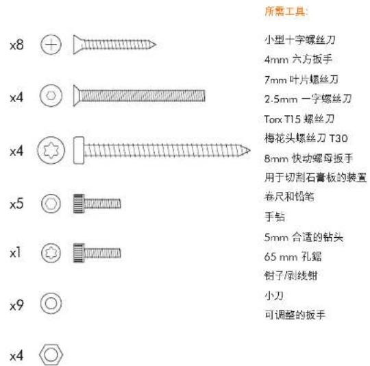
natural_image
Exploded view diagram of an electrical enclosure showing internal components and exploded views (no text or labels)
natural_image
Exploded view diagram of an electrical enclosure showing internal components and exploded view (no text or labels)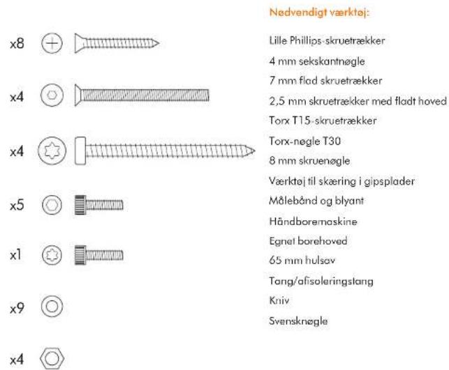
Installation of slange
natural_image
Exploded view diagram of an electrical enclosure showing internal components and exploded view (no text or labels)x8 ⊕
x4
x4
x5
x1
x9
x4
natural_image
Exploded view diagram of an electrical enclosure showing internal components and exploded view (no text or labels)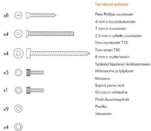
natural_image
Exploded view diagram of an electrical enclosure showing internal components and parts (no text or labels)x8


x4


x4


x5


x1


x9

x4

Outils requis :
Petit tournevis cruciforme
natural_image
Exploded view diagram of an electrical enclosure showing internal components and exploded view (no text or labels)x8


×4


x4

x5


x1


x9

x4

natural_image
Exploded view diagram of an electrical enclosure showing internal components and exploded view (no text or labels)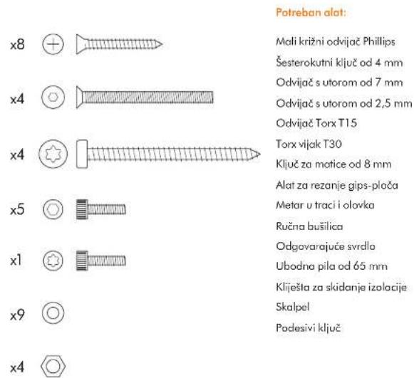
Potreban alat:
Mali križni odvijač Phillips
Šesterokutni ključ od 4 mm
natural_image
Technical line drawings of various electronic components and parts, including a fuse, spring, housing, and enclosure (no text or labels)x8


×4


x4


x5


x1


x9

x4

natural_image
Exploded view diagram of an electrical enclosure showing internal components and exploded view (no text or labels)x8


×4


x4

x5


x1


x9

x4

Kisaran suhu pengoperasian: 0°–40°C.
Konsumsi daya siaga:
kurang dari 0,5 W.
Ketinggian maksimum: 2.000 meter.
Pengoperasian air
natural_image
Pure technical line drawing of a mechanical component without any text, numbers, or symbols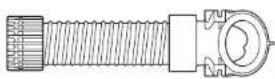
natural_image
Simple line drawing of a rectangular frame with a vertical oval cutout at the center (no text or symbols)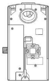
natural_image
Technical line drawing of a mechanical device interior (no text or symbols)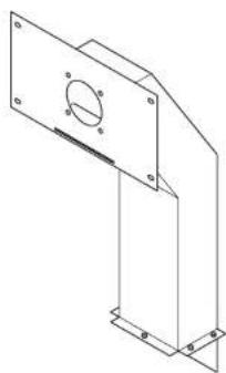
natural_image
Technical line drawing of a mechanical bracket with mounting holes and a circular feature (no text or symbols)
natural_image
Isometric line drawing of a rectangular box with two circular cutouts and mounting holes (no text or symbols)
natural_image
Exploded view diagram of an electrical enclosure and motor assembly (no text or labels)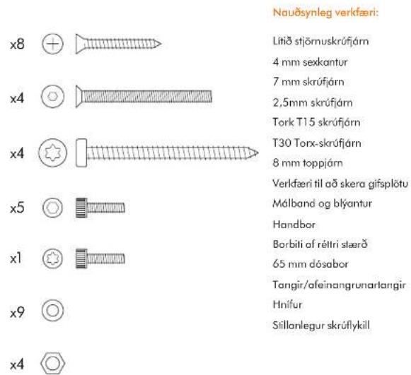
natural_image
Exploded view diagram of an electrical enclosure showing internal components and exploded view (no text or labels)x8


×4


x4


x5


x1


x9

x4

Strumenti necessari:
Cacciovite piccolo Phillips
natural_image
Technical line drawings of various electrical components and housing parts (no text or labels)x8

×4


x4

x5


x1


x9

x4

必要なツール:
小プラスドライバー
4mm 六角ドライバー
7mm ブレードスクリュードライバー
2.5mmマイナスドライバー
T15トルクスドライバー
T30 トルクスドライバー
8mm ナットスピナー
石こうボードカット器具
テープメジャーと鉛筆
ハンドドリル
適切なドリル用ビット
65mm ホールソー
ペンチ / ワイヤーストリッパー
カッターナイフ
スバナー
取り付け前の確認事項
图 A
取り付け前の確認事項
natural_image
Technical line drawings of various electrical components and housing parts (no text or labels)x8

×4


x4

x5


x1


x9

x4

필요한 공구:
소형 십자 드라이버
4mm 육각 드라이버
7mm 일자 드라이버
2.5mm 일자 드라이버
T15 별 드라이버
T30 별 드라이버
8mm 너트 스피너
석고보드 절단 공구
줄자 및 연필
핸드 드릴
적합한 드릴 비트
65mm 원통 돕
펜치/와이어 스트리퍼
칼
조절식 스패너
설치 전 확인사항
그림 A
설치 전 준비
natural_image
Technical line drawings of various electronic components and parts, including a fuse, spring, housing, and mounting bracket (no text or labels present)x8


×4


x4


x5


x1


x9

x4

Alatan diperlukan:
C= Suhu keluaryang dikehendaki
D= Injap pemencilan
E= Pemanas
natural_image
Technical line drawings of various electronic components and parts, including a fuse, spring, housing, and mounting bracket (no text or labels present)x8

x4

x4

x5


x1


x9

x4

natural_image
Pure electrical circuit lines without any symbols
natural_image
Simple line drawing of a rectangular frame with a horizontal line and a small oval cutout at the center (no text or symbols)
natural_image
Technical line drawing of a mechanical device interior (no text or symbols)
natural_image
Technical line drawing of a mechanical bracket with mounting flanges and a central circular feature (no text or symbols)


natural_image
Isometric line drawing of a 3D box with two circular cutouts and mounting holes (no text or symbols)x8


x4


x4

x5


x1


x9

x4

Verktøy som trengs:
Lite stjerneskrujern
4 mm bitsholder
natural_image
Pure technical line drawing of a mechanical component without any text, numbers, or symbols

natural_image
Simple line drawing of a rectangular frame with a horizontal line and a small oval shape at the center (no text or symbols)
natural_image
Technical line drawing of a mechanical device interior (no text or symbols)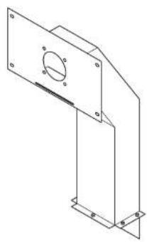
natural_image
Technical line drawing of a mechanical bracket with mounting holes and a central circular feature (no text or symbols)


natural_image
Isometric line drawing of a rectangular box with two circular cutouts on one side and two outer corners (no text or symbols)x8


x4


x4

x5


x1


x9

×4

Wymagane narzędzia:
natural_image
Pure technical line drawing of a mechanical component without any text, numbers, or symbols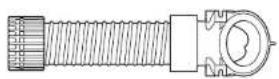

natural_image
Simple line drawing of a rectangular frame with a horizontal line and a small oval shape at the center (no text or symbols)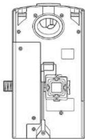
natural_image
Technical line drawing of a mechanical device interior (no text or symbols)
natural_image
Technical line drawing of a mechanical bracket with mounting holes and a central circular feature (no text or symbols)


natural_image
Isometric line drawing of a rectangular box with two circular cutouts on one side and two outer corners (no text or symbols)x8


x4


x4

x5


x1


x9

x4

natural_image
Technical line drawings of various electronic components and parts, including a fuse, spring, housing, and enclosure (no text or labels present)x8

x4

x4

x5


x1


x9

x4

The image contains no text.
©
©
◇
natural_image
Pure technical line drawing of a mechanical component without any text, numbers, or symbols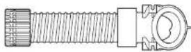
natural_image
Simple line drawing of a rectangular frame with a vertical oval cutout at the center (no text or symbols)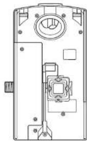
natural_image
Technical line drawing of a mechanical device interior (no text or symbols)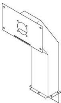
natural_image
Technical line drawing of a mechanical bracket with mounting holes and a circular feature (no text or symbols)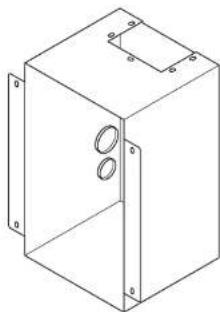
natural_image
Isometric line drawing of a rectangular box with two circular cutouts and mounting holes (no text or symbols)


DÔLEŽITÉ BEZPEČNOSTNÉ POKYNY
TIETO POKYNY SI PREČÍTAJTE A USCHOVAJTE
PRED MONTÁŽOU ALEBO POUŽITÍM TOHTO ZARIADENIA SI PREČÍTAJTE VŠETKY POKYNY A VAROVNÉ OZNAČENIA V TEJTO INŠTALAČNEJ PRÍRUČKE A V NÁVODE NA OBSLUHU.
VAROVANIE
VŠETKY MONTÁŽNE PRÁCE A OPRAVY (INŠTALATÉRSKE A ELEKTRIKÁRSKE) MUSÍ VYKONAT KVALIFIKOVANÁ OSOBA ALEBO SERVISNÝ TECHNIK SPOLOČNOSTI DYSON V SÚLADE S PLATNÝMI PREDPISMI ALEBO NARIADENIAMI.
VAROVANIE
NEBEZPEČENSTVO ÚRAZU ELEKTRICKÝM PRÚDOM!
V PRÍPADE NESPRÁVNEJ DEMONTÁŽE KRYTU ALEBO MANIPULÁCIE MÔŽU VNÚTORNÉ ČASTI PRÍSTROJA SPÓSOBIŤ PORANENIE ALEBO SA MÔŽU TRVALO POŠKODIŤ.
NA ZNÍŽENIE RIZIKA VZNIKU POŽIARU, ÚRAZU ELEKTRICKÝM PRÚDOM ALEBO ZRANENIA OSÓB MUSÍ BYŤ ZARIADENIE UZEMNENÉ.
natural_image
Exploded view diagram of an electrical enclosure showing internal components and exploded view (no text or labels)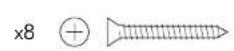


Potrebné náradie:
natural_image
Exploded view diagram of an electrical enclosure showing internal components and exploded view (no text or labels)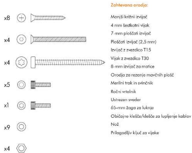
natural_image
Exploded view diagram of an electrical enclosure showing internal components and exploded view (no text or labels)x8

×4

x4

x5


x1


x9

x4

อุปกรณ์ต่อสิ้น
เชียงเจกขนาดเร็ก
4 mm.
7
*สตวัน 2.5 mm.
T15
T30
วิศน์ชันน้ํา 8 มม.
The image contains no legible text or symbols.
natural_image
Exploded view diagram of an electrical enclosure showing internal components and exploded view (no text or labels)x8


×4


x4


x5


x1


x9

×4

Gerekli aletler:
natural_image
Exploded view diagram of an electrical enclosure showing internal components and exploded view (no text or labels)x8


×4


x4


x5


x1


x9

x4

Important Safety Instructions 303
In the box 304
Pre-installation checks 305
Installation
Step-by-step 307
Test installation 309
Troubleshooting 309
IMPORTANT SAFETY INSTRUCTIONS
READ AND SAVE THESE INSTRUCTIONS
BEFORE INSTALLING OR USING THIS UNIT READ ALL INSTRUCTIONS AND CAUTIONARY MARKINGS IN THIS INSTALLATION GUIDE AND THE OWNERS MANUAL.
WARNING
ALL INSTALLATION AND REPAIR WORK (PLUMBING AND ELECTRICAL) SHOULD BE CARRIED OUT BY A QUALIFIED PERSON OR DYSON SERVICE TECHNICIAN IN ACCORDANCE WITH CURRENT LOCAL CODES OR REGULATIONS.
WARNING
RISK OF ELECTRIC SHOCK!
IF CASING IS REMOVED OR HANDLED IMPROPERLY THE INTERNAL COMPONENTS OF THE UNIT MAY CAUSE HARM OR BECOME PERMANENTLY DAMAGED.
THIS METAL ENCLOSURE MUST BE EARTHED TO REDUCE THE RISK OF FIRE, ELECTRIC SHOCK, OR INJURY TO PERSONS, OBSERVE THE FOLLOWING:
Before beginning any installation work you must confirm the following.
- Check that the electrical supply corresponds to that shown on the rating plate.
- A means for all-pole disconnection must be incorporated into fixed wiring, in accordance with local wiring regulations.
- Connect the electricity supply using suitable conduit and electrical fittings. Ensure that the conduit and wires are long enough to connect to the backplate and the terminal block. Solid metal conduit is not suitable for side entry.
WARNING
Use caution when unpacking the components. There may be sharp edges/corners which may cut or cause harm.
DO NOT USE ANY JET WASH EQUIPMENT FOR CLEANING ON OR NEAR THIS UNIT
In the box
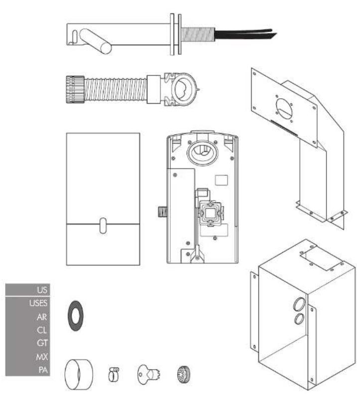
x8

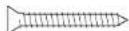
×4

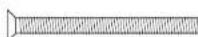
x4


x5


x1


x9

x4

Tools required:
Small Phillips screwdriver
4mm Hex drive
7mm blade screwdriver
Small bladed screwdriver
Torx T15 screwdriver
Torx drive T30
8mm nut spinner
Means for cutting plaster board
Tape measure and pencil
Hand drill
Suitable drill bit
65mm hole saw
Pliers/wire strippers
Knife
Adjustable spanner
Pre-installation checks
Fig. A
Pre-installation planning
The Dyson Airblade Wash+Dry hand dryer is designed so that the motor unit is located behind a stud wall within a metal enclosure which is supplied with the Dyson Airblade Wash+Dry. Fig. A(1)
The vertical wall studs must be constructed so as to allow the metal enclosure to be fitted between them. Refer to Fig. A(i).
- The unit is designed for dry, internal location only.
- Consult local and national accessibility codes and regulations for relevant installation guidelines. Conformity and compliance is the responsibility of the installer. Make sure that the unit is installed in compliance with all building codes and/or regulations.
- A means for all-pole disconnection must be incorporated into fixed wiring, in accordance with local wiring regulations.
- Isolate the power and water supplies before installation or service.
- Ensure no pipe work (gas, water, air) or electrical cables, wires or ductwork are located directly behind the drilling/mounting area.
- Dyson recommends the use of protective clothing, eye wear and materials when installing/repairing as necessary.
- This appliance is intended to be permanently connected to the water mains.
Use in food preparation areas
For food preparation environments special installation is required, which must fully enclose the motor bucket and hose in a cleanable housing or have the motor bucket on the reverse side of a wall, provide adequate clearance for cleaning underneath (if applicable) and be such that the unit is at least 8 feet from uncovered food or uncovered food-contact surfaces.
Refer to the Sink recommendation guide at www.dyson.com prior to install.
- Correct positioning of the: wall studs, wall surface, work surface and basin is essential for a successful installation as shown in
Fig. A(ii).
- The key measurement is from the center of the tap to the floor. The recommended distance is approximately 3', but this will differ depending on the height of the sink, refer to Template (Part 2).
- Allow sufficient access space for installation and servicing.
- If a series of units are to be fitted along a wall adjacent to each other, additional planning may be required.
Fig. B
Sink specification guidelines
Using a specially designed test method, Dyson engineers tested a wide range of sinks to assess their compatibility with the Dyson Airblade Wash+Dry hand dryer. For recommended sinks, please use our guide at www.dyson.com.
Porcelain or brushed metal sinks are ideal. Sinks with highly polished surfaces should be avoided e.g. reflective chrome. For minimum sink dimensions refer to Fig. B.
Fig. C/D/E
Tap mounting
There should be a minimum of 4" and a maximum of 6" from the top of the sink to the tap center. Fig. C.
There should be a minimum of 11" between a tap center and a side wall. When multiple taps are installed side-by-side, tap centers should be a minimum of 23" apart. This allows sufficient space for mounting the motor bucket, as well as sufficient shoulder room for users. Fig. D.
Do not place the downward facing water sensor of the top over a reflective surface, such as the drainage hole. Fig. E.
Fig. F
Soap and locating the soap dispenser
For best user experience, Dyson recommends the use of gel soap.
The infrared sensing zone for air activation extends along each tap branch. In order to prevent accidental activation, it's important to consider the user's hand route to the soap dispenser.
The dispenser should be located at least 2" outside the width of the tap, so the user reaches around the side of the branch. It should also be located at least 2" above the branches, so that the sensors are not activated.
Please note that the user may reach diagonally across for the soap, so this path must not go through the sensing zone.
Fig. G/H
Water drainage
Due to high velocity air and water being in close proximity, there is a chance of some water and soap dispersion outside the sink dimensions. To alleviate this effect, we recommend following the guidelines below.
Base Profile
Flat base profile will result in poor drainage leading to high levels of splashback. To improve drainage, avoid sinks with a flat base with particular focus on the immediate area surrounding the drain hole, minimum 2' radius. Fig. G.
Minimum of 6° ramp angle from the edge of the drain hole of the sink will result in good drainage leading to reduced levels of splashback (minimum 2" radius). Fig. H.
Fig. I/J/K
Base to back and front wall transition
The base to back and front wall transition should also be considered. The back wall should be as close to 90°, and at as sharp a radius as possible Fig. I. Curved geometry is more likely to increase splashback Fig. J, whereas sloping back and front wall transitions should be avoided Fig. K.
Fig. L
Plug hole
Plug holes with the most open aperture are recommended, whereas grille or perforated type plug holes should be avoided as they restrict the drainage of soapy water (lather). Do not use plugs within the plug holes in sinks.
Fig. M
Water temperature control
If you are connecting a hot and cold water feed you will need to install a blender valve.
If connecting to cold only water feed you will need to install a heater.
The water supply to this product must be fitted with a temperature control device in accordance with local regulations.
A= Blender valve
B= Hot and cold feed
C= Desired temperature out
D= Isolation valve
E=Hecter
F = Cold feed in
Fig. N
Installing
The main unit must be mounted on a flat vertical wall capable of supporting the full weight of the unit.
One of the horizontal wall studs must be fitted a) so it holds the main weight of the metal duct and the unit, and b) so it is in the correct position for the tap stem.
The unit must be installed using the supplied duct, duct cover and metal enclosure.
Do not use sealant when fixing the unit to the wall.
Ensure electricity and mixed water supplies and drainage connections are available for connection. Suitable isolation of the power and water supplies must be in place to switch off supplies before install and for servicing.
Electrical
Input voltage/Frequency: Refer to rating plate. Isolated by switch fuse spur or RCD as appropriate.
Current 6.6 A.
Local electrical regulations must be adhered to when installing or repairing the product. Rated power: Refer to rating plate.
Operating temperature range: 32° – 104°F. Standby power consumption:
Less than 0.5 W
Maximum altitude: 6500'.
Water operation
Water flow rate: 0.5 gal/min normal fitter aerator, 0.35 gal/min with low flow aerator supplied with product.
Water pressure required: 14.5-116 psi isolated valve required for service.
Keep secondary hot water return as close to blender valve as possible to reduce the risk of Legionella bacteria growth.
Water supply cleanliness and biological growth
In some countries there are regulations or guidelines that require temperature controlled water supply systems (such as that supplied to the Dyson Airblade Wash+Dry hand dryer) to be subjected to regular cleaning to minimize any biological growth. To enable you to meet these regulations, the Dyson Airblade Wash+Dry hand dryer has been designed and tested to withstand internal cleaning both with hot water up to 203°F and with sodium hypochlorite at a concentration of 0.45%.
Please refer to specific (market) regulations and water supply system recommendations for information on cleaning regimes for water supply cleanliness and biological growth for your country.
When carrying out internal cleaning of the Dyson Airblade Wash+Dry hand dryer, please be aware of any safety considerations when using hot water or chemicals. Dyson will not be responsible for any injury caused by this process.
Abusive testing
The Dyson Airblade Wash + Dry hand dryer has undergone rigorous abusive testing to ensure that it can withstand substantial forces and impacts typical of a commercial and public bathroom environment.
Step-by-step
Fig. 1/2
Assemble enclosure
Assemble the metal enclosure and ducting as shown in Fig. 1 using the 5 x hex head bolts and washers supplied.
Construct the wall studding ensuring
adequate space to fit the metal enclosure and ducting as shown in Fig. 2.
The key measurement is from the center of the tap to the floor. The recommended distance is approximately 3' but this will differ depending on the height of the sink, refer to Template (Part 2).
Fig. 3
Enclosure mounting
Fit the enclosure and ducting into the wall studs and mark the location of the 8 x screw holes on the wall studs using the fixing holes in the enclosure and ducting as a guide.
Ensure that the enclosure is pushed up against the top horizontal stud to set correct tap height and that it is level Fig. 3.
Remove the enclosure and ducting and drill 8 x fixing holes using a suitable drill bit for the 8 x M5 wood screws Fig. 3.
CAUTION: Do not use the enclosure and ducting as a guide when drilling.
Fix the enclosure and ducting into the wall studs and fix using the 8 x countersunk screws provided Fig. 3.
Fig. 4
Installation of power and water supply and earth
WARNING: Risk of electric shock!
Ensure that the power supply is switched off before continuing.
NOTE: The enclosure must be earthed.
Pierce a small hole in the lower grommet and feed through the electrical supply as shown. Use suitable conduit and electrical fittings.
Pierce a small hole in the upper grommel and feed through the mixed water supply as shown. Flexible conduit with a 12 " BSP connection should be used.
Connect earth cable to one of the M5 studs in the top of the enclosure following local electrical guidelines/regulation
A=Water
B= Electric
Fig. 5
Installing plasterboard
Measure the position of the lap mounting hole from a suitable horizontal and vertical reference as shown.
Mark the center of the tap mounting hole on the plasterboard using the measured dimensions.
Use this mark to position the template on the plaster board and cut and drill holes for the top stem, the stem fixing holes, the access hole and access panel fixing holes as detailed on the Template (Part 2).
Line up the holes in the plasterboard with the holes in the enclosure and ducting and attach the plasterboard to the wall studding using appropriate fixings.
Fit sink and work surface as required.
Finish the wall surface as required.
Clean and remove any dust or debris from the inside of the enclosure.
Fig. 6
Preparing for installation of backplate Remove the motor bucket from the backplate by pressing the red release catch at the bottom and lifting up as shown in Fig. 6a. Store the motor bucket safely until required. Remove the water pipe cover and the electrics cover from the backplate as shown in Fig. 6b and 6c. Store them safely along with fixings until required.
Fig. 7
Backplate installation
Fix the backplate onto the metal studs inside the enclosure and secure with the 4 x M5 nuts and washers supplied as shown in Fig. 7.
Fig. 8
Hose Installation
Unscrew the cover plate from the tap stem. Slide the rubber seal over the water tube and sensor cable and onto the tap stem as shown in Fig. 8a.
Slide the grey hose up over the water tube and sensor cable Fig. 8b.
Feed the water tube through the left exit hole in the hose duct as shown in Fig. 8c.
Use pliers to gently pull the water tube through as far as the solid white line Fig. 8d. Ensure the grommet on the water tube fits tightly into the hose duct so that it is airtight Fig. 8e.
Feed the sensor cable through the right exit hole as shown in Fig. 8c. DO NOT use pliers as this may damage the electrical connections Fig. 8d. Ensure the grommet on the cable fits tightly into the hose duct so that it is airtight Fig. 8e.
Screw the upper hose collar onto the tap stem so that it is hand tight Fig. 8f.
A= Rubber seal
B= Water tube
C = Sensor cable
D = Grey hose
Fig. 9
Secure tap
Feed the hose through the hole in the plasterboard and into the metal duct. The rubber seal should now fit between the tap stem and the wall Fig. 9a.
Fix the tap to the plasterboard wall, lining up the mounting holes and making sure that the tap sits flat on the rubber seal and wall Fig. 9b.
Attach the tap to the ducting behind the plasterboard using the 4 x M5 CSK screws supplied as shown in Fig. 9b making sure that the tap is level before fully tightening.
Screw the cover plate over the tap mounting plate and tighten to hand tight Fig. 9c.
A= Rubber seal
B = Grey hose
C = Tap stem
D= Cover plate
Fig. 10
Connecting the tap
Clip the grey hose into the backplate.
Plug the sensor cable in the hose into the connector in the backplate as shown in Fig. 10. Check the orientation of the connector; the two tabs must be lined up. Ensure the cable is correctly routed in the backplate.
Fig. 11
Connecting the water tube
Cut the water tube to size at the dotted white line as shown in Fig. 11a.
Slide the hose clip (supplied) onto the water tube Fig. 11b.
Remove the 2 x Phillips screws and unclip the solenoid from the backplate Fig. 11b.
Attach the water hose to the solenoid Fig. 11c. Clip the solenoid back on to the backplate and fasten the 2 x screws Fig. 11d.
Tighten the hose clip and ensure the solenoid cable is correctly positioned in the retaining channel.
Fig. 12
Connecting the electricity supply Route the electricity supply to the backplate using approved flexible or solid conduit and fittings. Ensure the power cable is long enough to connect to the terminal block mounted in the back plate.
Route the cable into the backplate and tighten the cable gland.
Strip the cable to a suitable length and secure the live and neutral wires into the corresponding terminal blocks as shown in Fig. 12. Ensure the correct positioning of the cables before proceeding.
Fig. 13
Re-assemble electrical cover
Fix the electrics cover and secure with the 6 x fixings supplied ensuring no wires are trapped.
Fig. 14
Connecting the mixed water supply
Ensure water feed has been completely flushed of debris, copper filings etc. prior to connecting to the backplate. Failure to do so may damage the solenoid valve resulting in it not closing properly, creating a a dripping tap.
Connect the isolated, mixed water supply to the backplate.
Turn on the water.
Inspect for leaks at the main water supply inlet and the water tube connection to the tap.
Also check for leaks at the solenoid connection.
Fig. 15
Switching power on
Switch on power to the machine.
CALIBRATION CYCLE: Once installed, the tap will go through a 30 second calibration cycle.
Place hand under sensor on tap to activate water flow.
Check for leaks as per Fig. 14.
Secure the water pipe cover onto the backplate using the 2 x fixings provided.
Fig. 16
Assembling the motor bucket
Hook the motor to the top of the electrics cover. Swing it downwards so it clicks into place as shown. Push in securely.
OPTIONAL: A screw is supplied to secure the red release button and prevent unwanted removal of the motor bucket.
Test the unit for correct operation.
Fig. 17
Fitting the access panel
Fix the access panel to the plasterboard using the 4 x M6 screws.
US
USES
AR
CL
GT
MX
PA
installation
Test the hand dryer for normal operation:
- Place your hands beneath the center of the tap and water will flow automatically for as long as the hands remain in place.
- Place your hands to either side of the center tap to activate the hand dryer, creating sheets of air to scrape water from your hands.
- Move your hands backwards and forwards slowly through the air, turning them over so both back and front are exposed to the airflow.
Automatic duty flush
The unit is equipped with a fixed automatic water flush, which activates for 60 seconds 24 hours after last use. This helps reduce water stagnation and bacteria proliferation within the product.
Please ensure that the unit is always installed over a functional basin with free and connected drainage.
TroubleshootingTest
Hand dryer fails to start:
- Check fuse/circuit breaker is working and that the power and water supply are connected.
- Ensure the cleaning cap is removed and that the sensors are clean and unobstructed.
- Turn the unit off and on.
Hand dryer turns itself on and off erratically:
– Turn the unit off and on.
- Ensure there is no plug in the sink and remove if plug is present.
- Ensure sensors are clean.
- Check that the sensor cable from the tap is securely connected.
Hand dryer sometimes cuts out in use:
- Turn the unit off and on.
– Ensure sensors are clean.
- Check the air inlets are clean and free of dust. If the air inlets are dusty simply remove dust.
- Ensure that the air inlets are free from obstructions and have sufficient clearance.
The dry time has increased:
- Inspect the air inlets for dust and remove.
– Inspect filter and change if required.
- Ensure that the hose is securely attached to the base of the tap and no leaks are present.
The airflow is running hotter than usual:
- Inspect the air inlets for dust and remove.
– Inspect filter and change if required.
- Ensure that the hose is securely attached to the base of the tap and no leaks are present.
Air is continuously running:
– Check for any object in the sink and remove if necessary.
- Ensure sensors are clean and free from any obstructions.
– Inspect filter and change if required.
- Ensure that the hose is securely attached to the base of the tap and no leaks are present.
There is no air running:
– Turn the unit off and on.
- Check fuse/circuit breaker is working and that the power is connected.
– Ensure sensors are clean.
- Ensure that the air hose is securely attached to the base of the tap and no leaks are present.
- Check that the sensor cable from the tap is securely connected.
Water is continuously coming from the tap:
- Ensure sensors are clean and free from any obstructions.
There is no water coming from the tap:
- Ensure that the power and water supplies are turned on and that the isolation valve is open.
- Ensure that the aerator is free from debris, remove and clean/replace if necessary.
The water coming from the tap is overly hot or cold:
- Check the blender valve is set to the desired temperature.
Contact Dyson Customer Care for further support and information or online at www.dyson.com
USES/AR/CL/GT/MX/PA
Contenido
x8


x4

x4

x5


x1


x9

x4

Installation Drawings
Схеми За Монтаж
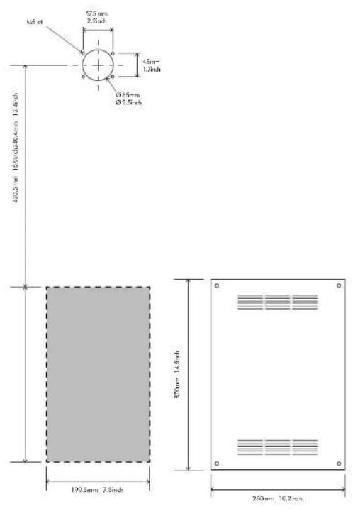
B
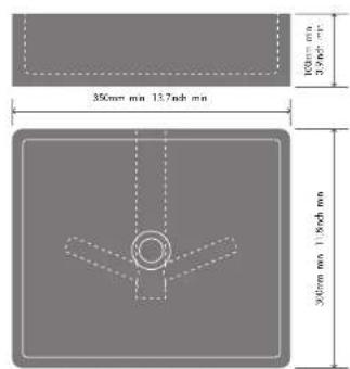
C
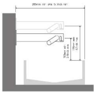
D
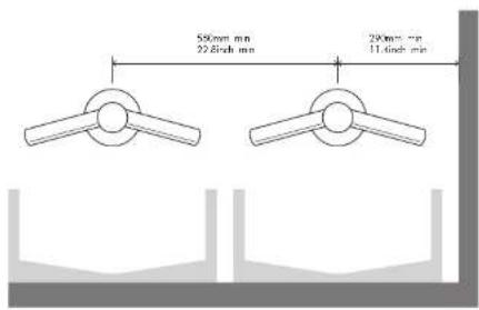
E
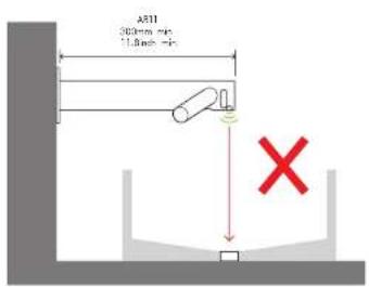
F
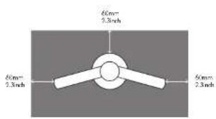
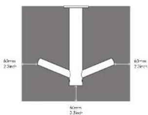
G
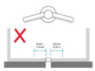
H
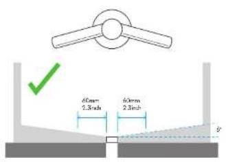
|
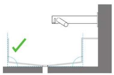
natural_image
Diagram showing a mechanical setup with a green checkmark and a vertical rod, no text or symbols present.JKL
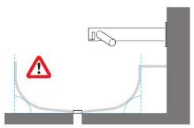
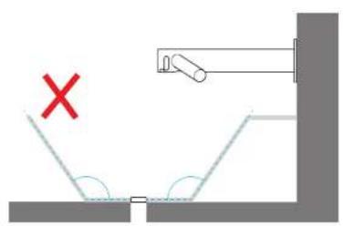
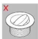
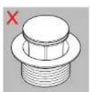
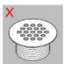
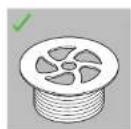
M
N
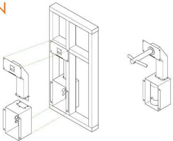
natural_image
Technical line drawing of a mechanical assembly with two views: one showing internal components and the other a bracket (no text or symbols)1
×5


×5

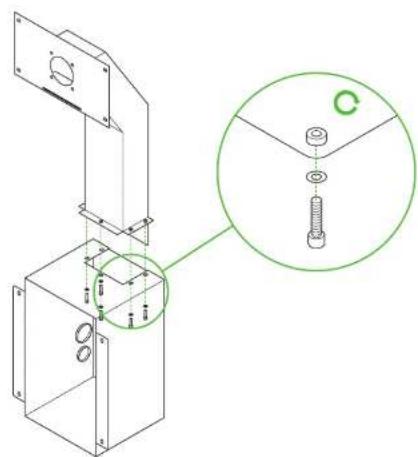
2
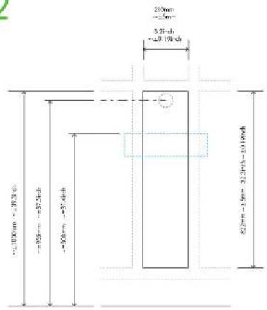
3
×8

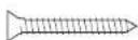
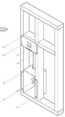
natural_image
Isometric line drawing of a cabinet or shelf assembly with internal components and directional arrows (no text or symbols)4

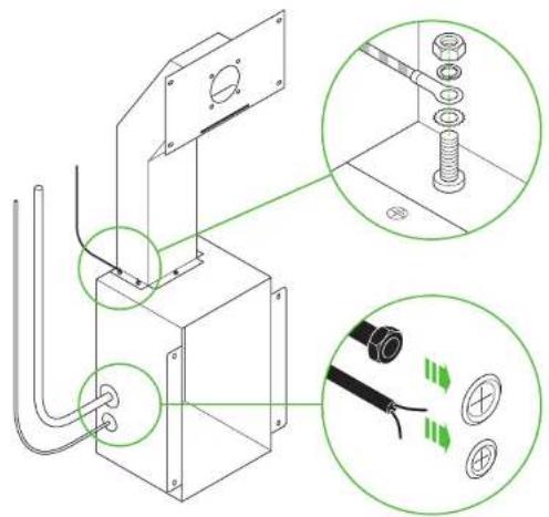
5
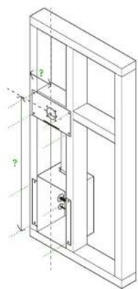
natural_image
Isometric line drawing of a cabinet or shelf unit with internal compartments and dimension lines (no text or symbols)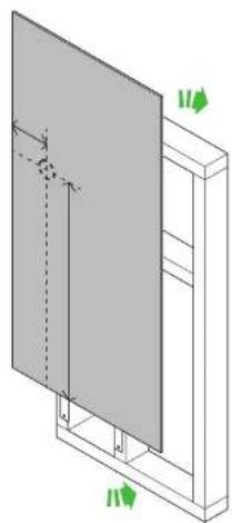
natural_image
3D diagram of a structural panel with arrows indicating direction (no text or symbols)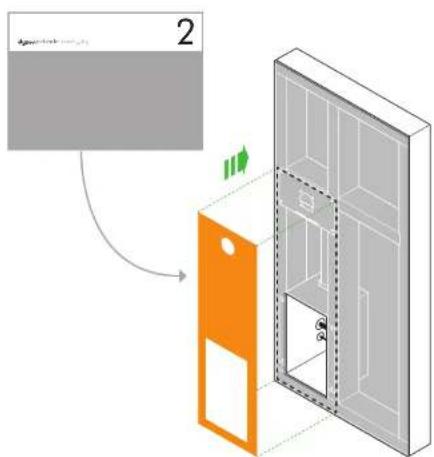
6a 6b 6c
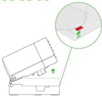
natural_image
Technical diagram of a mechanical assembly with a magnified inset showing a 3D mesh structure and green arrows indicating motion (no text or symbols)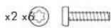

natural_image
Technical line drawing of a mechanical assembly with internal components and mounting holes (no text or symbols)
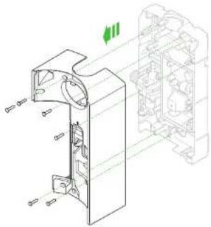
natural_image
Technical line drawing of a mechanical assembly with internal components and mounting holes (no text or symbols)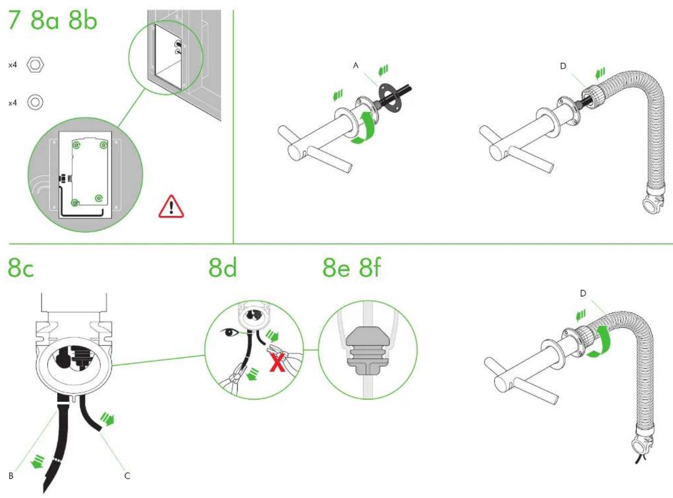
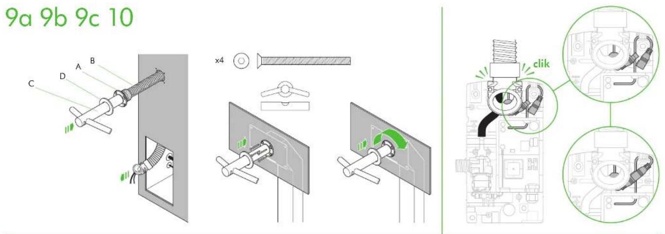
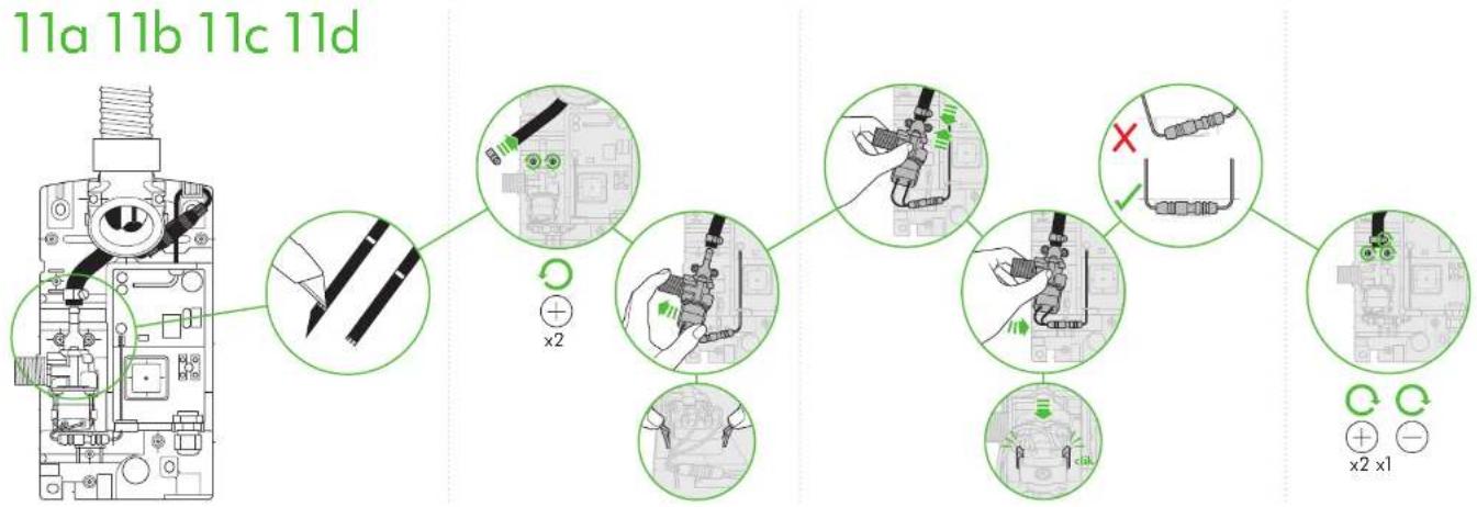
flowchart
graph TD
    A["11a 11b 11c 11d"] --> B["Switch Component"]
    B --> C["Disassembly to 11a/11b/11c"]
    C --> D["Electrical Wiring Changes"]
    D --> E["Switch Component"]
    E --> F["Disassembly to 11a/11b/11c"]
    F --> G["Electrical Wiring Changes"]
    G --> H["Switch Component"]
    H --> I["Disassembly to 11a/11b/11c"]
12 13 14
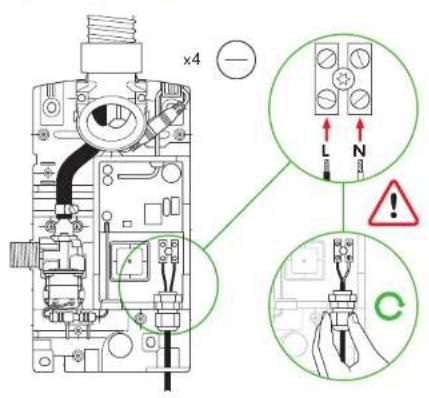
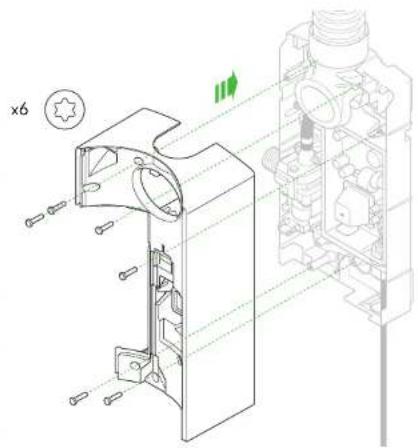
natural_image
Technical line drawing of a mechanical assembly with exploded view and cross-section view (no text or symbols)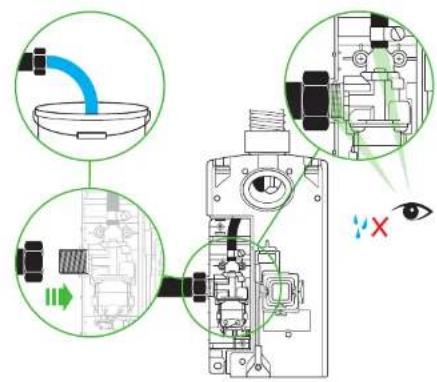
15 1716
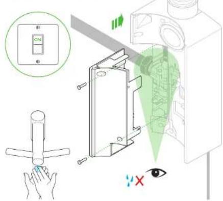
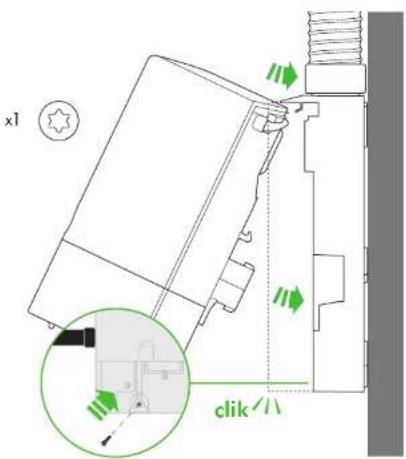
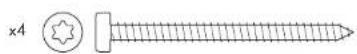
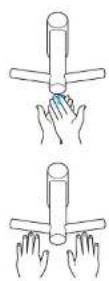
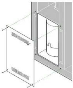
natural_image
Technical line drawing of a door opening with ventilation grilles and a cylindrical component inside (no text or symbols)Dyson Customer care www.dyson.com
UK (+44) 0800 345 7788 www.dyson.co.uk
ROI (+353) 01 401 8300 www.dyson.ie
AE (+971) 4 507 6000 www.dyson.ae
AR (+1) 855 720 6378 www.dyson.com.ar
AT (+43) 0800 8866 7343 www.dyson.at
AU (+61) 1800 426 337 www.dyson.com.au
BE (+32) 0800 39 209 www.dyson.be
BG (+359) 2 968 1111 www.dyson.bg
BH (+971) 4 507 6000 www.dyson.ae
natural_image
Pure geometric diagram with diagonal hatching and centerlines, no text or symbols presentDyson Customer care
www.dyson.com
UK -441 0506 345 7782
KJ 1+5.70, 1086, 307/3
[Unreadable]
www.dts.com.cn
18 -9011 1253 474
公司公告的公告内容如下:
10 + 31 320 62432
NO. 130121 0520 0532
+5611012917
M (+351,600,784,205)
K. 1+7 as no1 001 no2
(1) 2017年1月1日星期六
www.noah-fund.com
华
www.dsc.com
501(45)86432992
(1) 2017年1月1日
Source: http://www.163.com.cn
4.1-085(9)36-813V
IMPORTANT SAFETY INSTRUCTIONS READ AND SAVE THESE INSTRUCTIONS
BEFORE INSTALLING OR USING THIS UNIT READ ALL INSTRUCTIONS AND CAUTIONARY MARKINGS IN THIS MANUAL AND THE INSTALLATION NOTES.
TO REDUCE THE RISK OF FIRE, ELECTRIC SHOCK OR INJURY TO PERSONS, OBSERVE THE FOLLOWING:
- This unit is not intended for use by persons (including children) with reduced physical, sensory or reasoning capabilities, or lack of experience and knowledge, unless they have been given supervision or instruction concerning use of the unit by a person responsible for their safety.
- Do not allow the unit to be used for any purpose other than washing and drying hands. Use this unit only in the manner intended by the manufacturer. If you have questions, contact the manufacturer.
- Before servicing, switch the power off at the service panel. Ensure the switch is locked to prevent the power from being switched on accidentally. If the means of switching off the power cannot be locked, securely fasten a prominent warning device, such as a tag, to the service panel.
Children should be supervised to ensure that they do not play with the unit.
DO NOT USE ANY PRESSURE WASHING EQUIPMENT FOR CLEANING ON OR NEAR THIS UNIT.
WARNING
TO REDUCE THE RISK OF FIRE OR ELECTRIC SHOCK, DO NOT USE THIS APPLIANCE WITH ANY SOLID-STATE SPEED CONTROL DEVICE.
ALL INSTALLATION AND REPAIR WORK (PLUMBING AND ELECTRICAL) SHOULD BE CARRIED OUT BY A QUALIFIED PERSON OR DYSON SERVICE ENGINEER IN ACCORDANCE WITH CURRENT LOCAL CODES OR REGULATIONS.
CAUTION
Your hand dryer should be located indoors. Operating temperature range 0^ C ( 32^ F) to 40^ C ( 104^ F). To reduce the risk of fire or electric shock, do not expose the internal mechanisms/components of this unit to moisture.
THANK YOU FOR CHOOSING TO BUY A DYSON AIRBLADE WASH+DRY HAND DRYER
DYSON CUSTOMER CARE
Your hand dryer is covered for 5 years from the date of purchase, subject to the terms of the limited guarantee.
Register your guarantee now at: www.dyson.com.
If you have any questions about your hand dryer, call the Dyson Helpline with your serial number and details of where and when you bought the unit.
Note your serial number here for future reference.
Your serial number can be found on the bottom right hand corner of the backplate, on a registration sheet in the box, and also on the large information sticker which can be found around the tap when the unit is unpacked.
This illustration is for example purposes only.
A comprehensive installation guide is enclosed with the hand dryer packaging. This contains detailed information on the correct installation of the unit, which MUST be adhered to completely, including routing of electrical cables. Damage caused by incorrect installation is not covered by your warranty. The fitting of an in-line filter is advised to prevent any damage that may affect your guarantee.
NOTE: Ensure water feed is completely flushed of debris, copper filings etc. prior to connecting to the product. Failure to do so will damage the solenoid valve. The instructions in this manual and the installation guide must be followed completely, as failure to do so may result in incorrect operation, damage to property and/or personal injury. It is recommended that an isolation valve is fitted with this product during installation. Dyson will not be held liable for any damage to property or personal injury, or any loss of business or revenue, if you, your staff, your installer or service engineers have not followed the instructions given in this manual and the installation guide.
LOOKING AFTER YOUR HAND DRYER
WARNING
This product is not to be used in sinks where a plug is fitted. Before engaging the water flow ensure that the plughole is clear of any obstructions and that water can drain freely.
HOW TO USE
Place your hands beneath the Dyson hand dryer and it will automatically, creating sheets of air to scrape water from your hands.
For best dry time results:
- Keep your hands flat and parallel to the appliance surface, approximately 5 mm from the blade, drawing your hands through the airflow from your wrists to finger tips.
- Move your hands slowly through the airflow keeping a consistent speed, approx. 2.5 seconds per side, alternating between front and back each time.
- Keep you hands flat, close the gaps between your fingers and keep your thumbs in to ensure that the whole of your hand is drawn through the airflow.
TROUBLESHOOTING GUIDE
⚠ WARNING: RISK OF ELECTRIC SHOCK!
| Problem Action | |
| The hand dryer fails to start. Check that the fuse/circuit breaker is working and that the power is connected. Must be performed by a qualified electrician.Ensure that the cleaning cap is removed and that the sensors are clean and unobstructed. If a safe method of switching is available, turn the unit on and off. If a safe method is not available, a qualified electrician must perform this task. | |
| The hand dryer is turning on and off eneratically. | Ensure that the sensors are clean and free from obstructions.Check that the sensor cable from the tap is securely connected. Must be performed by a qualified electrician. |
| The hand dryer sometimes cuts out when in use but resumes operation after a period of time. | Check that the air inlet is clean and free of dust.Remove any dust from the air inlet.Ensure that the air inlet is free from obstructions and has sufficient clearance (see installation instructions). |
| The dry time of the hand dryer has increased. Inspect the inlet grille for dust and remove.Inspect the filter and change if required.Ensure that the hose is securely attached to the base of the tap and no leaks are present.Must be performed by a qualified electrician. | |
| Air is continuously running from the hand dryer. | Ensure that the sensors are clean and free from obstructions. |
| There is no air coming from the hand dryer. Check that the fuse/circuit breaker is working and that the power is connected. Must be performed by a qualified electrician.Ensure that the air hose is securely attached to the base of the tap and no leaks are present. Must be performed by a qualified electrician.Check that the sensor cable from the tap is securely connected. Must be performed by a qualified electrician. | |
TAP
| Problem Action | |
| Water is continuously coming from the tap. Ensure that the sensors are clean and free from obstructions. | |
| There is no water coming from the tap. Ensure that the power and water supplies are turned on and that the isolation valve is open. Must be performed by a qualified electrician. Ensure that the aerator is free from debris, remove and clean/replace if necessary. | |
| The water coming from the tap is overly hot or cold. | Contact the Dyson Helpline. |
If you have any further questions please contact the Dyson Helpline.
USE IN FOOD PREPARATION AREAS
For food preparation environments special installation is required, which must fully enclose the motor bucket and hose in a cleanable housing or have the motor bucket on the reverse side of a wall, provide adequate clearance for cleaning underneath (if applicable) and be such that the unit is at least 2.5 metres from uncovered food or uncovered food-contact surfaces.
CLEANING
The hand dryer should be cleaned daily.
Wipe sensors using a soft cloth and non-abrasive cleaner then place cleaning cap over sensors to prevent air and water from being activated.
Clean all tap surfaces, sink, mirror and any walls or counter tops. When complete REMEMBER to remove cleaning cap.
REGULARLY clean air inlets on base of motor bucket (under sink). Ensure that the plughole in sink is free from blockages so water can drain freely.
IMPORTANT INFORMATION
Do not pressure wash the machine.
All cleaning chemicals should be used exactly as indicated by the manufacturer's instructions (including appropriate dilution).
If a cleaning product is left on the machine for too long, a film will form. This may reduce the effectiveness of the antimicrobial surfaces.
Any chemicals intended for use should first be tested on an inconspicuous area to confirm suitability. Aside from cleaning chemicals, care should be taken to avoid any harmful fluids from coming into contact with the product, in particular oils and alcohol-based products.
WATER GUIDELINES
This hand dryer has an IP35 certification.
Use of pressure washers can force water inside the casing.
Water damage caused by incorrect cleaning will invalidate your guarantee.
AUTOMATIC DUTY FLUSH
The unit is equipped with a fixed automatic water flush, which activates for 60 seconds 24 hours after last use. This helps reduce water stagnation and bacteria proliferation within the product.
Please ensure that the unit is always installed over a functional basin with free and connected drainage.
SOLENOID REPLACEMENT GUIDELINES
It may be necessary to replace the solenoid on your hand dryer. If you suspect that this is the case, please contact the Dyson Helpline.
When replacing the solenoid, the hand dryer must be disconnected from the mains electricity and water supply. Failure to do so could lead to serious injury and/or damage to property.
FILTER MAINTENANCE
Regularly check the air inlet to ensure that it is free from dust and debris. Simply wiping the inlet with a soft cloth should be sufficient to remove dust and debris.
If the air inlet gets clogged, further cleaning or a filter change might be required. If required for high usage environments, a Dyson filter change kit provides everything needed to change your unit's HEPA filter on site. Contact the Dyson Helpline for more information. Filter cleaning or replacement for your hand dryer can be carried out by carefully following the instructions given in the filter change kit. If in any doubt, consult a qualified electrician or contact the Dyson Helpline for support.
SERVICING
If your hand dryer needs servicing, please call the Dyson Helpline. Also visit the website at www.dyson.com.
DISPOSAL INFORMATION
Dyson products are made from high grade recyclable materials. Recycle where possible.
YOUR GUARANTEE
Terms and conditions of the Dyson 5 year guarantee
If you have registered your unit online, your guarantee will start from the date of purchase. Please retain your proof of purchase. If you do not have your proof of purchase, your guarantee will start 90 days after the date of manufacture, according to Dyson's records.
Where this unit is sold within the EU, this guarantee will only be valid (i) if the unit is installed and used in the country in which it was sold or (ii), if the unit is installed and used in Austria, Belgium, France, Germany, Ireland, Italy, Netherlands, Spain or the United Kingdom and the same model as this unit is sold at the same voltage rating in the relevant country. Where this unit is sold outside of the EU, this guarantee will only be valid if the unit is installed and used in the country in which it was sold.
WHAT IS COVERED
5 YEAR GUARANTEE
All factory parts of your hand dryer are guaranteed against original defects, material and workmanship when used in accordance with the owner's manual and installation guide for a period of 5 years from the start of your guarantee.
Please call the Dyson Helpline for more information.
In instances where electrical failures occur, Dyson will, during the guarantee period carry out the repair with no labour charge.
The replacement of the motor bucket assembly, filter and solenoid are not covered for labour. If these parts fail, replacement parts will be provided to be fitted on site by the customer.
Please call the Dyson Helpline for more information.
Where a filter change is required, Dyson will provide a filter change kit to be installed on site by the customer.
• Any parts which are returned and replaced by Dyson will become the property of Dyson.
- The replacement of any part of your unit under guarantee will not extend the period of guarantee.
- The guarantee provides benefits which are additional to and do not affect any statutory rights you may have as a consumer.
WHAT IS NOT COVERED
Dyson does not guarantee the repair or replacement of a product as a result of:
- Accidental damage, faults caused by negligent use or care, unintentional or deliberate misuse, neglect, vandalism, careless operation or handling of the fixture which is not in accordance with the Dyson operating manual.
- Use of parts not assembled or installed in accordance with the instructions of Dyson.
- Use of parts and accessories which are not genuine Dyson components.
- Faulty installation, or installation that does not precisely follow the installation instructions supplied by Dyson (except where installed by Dyson).
• Repairs or alterations carried out other than in accordance with instructions by Dyson. - Damage from external sources such as transit, weather, electrical outages or power surges.
• Normal wear and tear (e.g. fuse, etc.). - Damage caused by cleaning which is not in line with the instructions in this manual: for example, cleaning with chemicals or products listed as harmful to the unit.
- Damage caused by water ingress due to cleaning or treatment prohibited in this manual.
- Any electrical, flooding or structural damage, or any loss of business or revenue as a result of product failure. If you are in any doubt as to what is covered by your guarantee, please contact Dyson (details on the back cover).
SUMMARY OF COVER
- You must provide proof of (both the original and any subsequent) delivery/purchase before any work can be carried out on your Dyson appliance or before any replacement parts will be supplied. Without this proof, any work carried out or parts supplied will be chargeable. Keep your receipt or delivery note.
- Subject to the exclusions above, all work to be carried out under this guarantee will be carried out by Dyson or its authorised agents.
IMPORTANT DATA PROTECTION INFORMATION
When registering your Dyson product:
- You will need to provide us with basic contact information to register your product and enable us to support your guarantee.
- When you register, you will have the opportunity to choose whether you would like to receive communications from us. If you opt-in to communications from Dyson, we will send you details of special offers and news of our latest innovations. We never sell your information to third parties and only use information that you share with us as defined by our privacy policies which are available on our website: privacy.dyson.com.
AU/NZ
IMPORTANT SAFETY INSTRUCTIONS READ AND SAVE THESE INSTRUCTIONS
BEFORE INSTALLING OR USING THIS UNIT READ ALL INSTRUCTIONS AND CAUTIONARY MARKINGS IN THIS MANUAL AND THE INSTALLATION NOTES.
TO REDUCE THE RISK OF FIRE, ELECTRIC SHOCK OR INJURY TO PERSONS, OBSERVE THE FOLLOWING:
- This unit is not intended for use by persons (including children) with reduced physical, sensory or reasoning capabilities, or lack of experience and knowledge, unless they have been given supervision or instruction concerning use of the unit by a person responsible for their safety.
- Do not allow the unit to be used for any purpose other than washing and drying hands. Use this unit only in the manner intended by the manufacturer. If you have questions, contact the manufacturer.
- Before servicing, switch the power off at the service panel. Ensure the switch is locked to prevent the power from being switched on accidentally. If the means of switching off the power cannot be locked, securely fasten a prominent warning device, such as a tag, to the service panel.
- Children should be supervised to ensure that they do not play with the unit.
DO NOT USE ANY PRESSURE WASHING EQUIPMENT FOR CLEANING ON OR NEAR THIS UNIT.
WARNING
TO REDUCE THE RISK OF FIRE OR ELECTRIC SHOCK, DO NOT USE THIS APPLIANCE WITH ANY SOLID-STATE SPEED CONTROL DEVICE
ALL INSTALLATION AND REPAIR WORK (PLUMBING AND ELECTRICAL) SHOULD BE CARRIED OUT BY A QUALIFIED PERSON OR DYSON SERVICE ENGINEER IN ACCORDANCE WITH CURRENT LOCAL CODES OR REGULATIONS.
CAUTION
Your hand dryer should be located indoors. Operating temperature range 0^ C ( 32^ F) to 40^ C ( 104^ F). To reduce the risk of fire or electric shock, do not expose the internal mechanisms/components of this unit to moisture.
THANK YOU FOR CHOOSING TO BUY A DYSON AIRBLADE WASH+DRY HAND DRYER
DYSON CUSTOMER CARE
Your hand dryer is covered for 5 years from the date of purchase, subject to the terms of the limited guarantee.
Register your guarantee now at: www.dyson.com.au or www.dyson.co.nz. If you have any questions about your hand dryer, call the Dyson Helpline with your serial number and details of where and when you bought the unit.
Note your serial number here for future reference.

Your serial number can be found on the bottom right hand corner of the backplate, on a registration sheet in the box, and also on the large information sticker which can be found around the tap when the unit is unpacked.
This illustration is for example purposes only.
A comprehensive installation guide is enclosed with the hand dryer packaging. This contains detailed information on the correct installation of the unit, which MUST be adhered to completely, including routing of electrical cables. Damage caused by incorrect installation is not covered by your guarantee.
The fitting of an in-line filter is advised to prevent any damage that may affect your guarantee.
NOTE: Ensure that the water feed is completely flushed of debris, copper filings etc. prior to connecting to the product. Failure to do so will damage the solenoid valve. The instructions in this manual and the installation guide must be followed completely, as failure to do so may result in incorrect operation, damage to property and/or personal injury. It is recommended that an isolation valve is fitted with this product during installation. Dyson will not be held liable for any damage to property or personal injury, or any loss of business or revenue, if you, your staff, your installer or service engineers have not followed the instructions given in this manual and the installation guide.
AU NZ
LOOKING AFTER YOUR HAND DRYER
WARNING
This product is not to be used in sinks where a plug is fitted. Before engaging the water flow ensure that the plughole is clear of any obstructions and that water can drain freely.
HOW TO USE
Place your hands beneath the centre of the tap and water will flow automatically for as long as the hands remain in place.
For best dry time results:
- Place your hands to either side of the centre top to activate the hand dryer, creating sheets of air to scrape water from your hands.
- Move your hands backwards and forwards slowly through the air, turning them over so both back and front are exposed to the airflow.
- Keep you hands flat, close the gaps between your fingers and keep your thumbs in to ensure that the whole of your hand is drawn through the airflow.
TROUBLESHOOTING GUIDE
⚠ WARNING: RISK OF ELECTRIC SHOCK!
| Problem Action | |
| The hand dryer fails to start. Check fuse/circuit | breaker is working and that the power is connected. Must be performed by a qualified electrician.Ensure the cleaning cap is removed and that the sensors are clean and unobstructed.If a safe method of switching is available, turn the unit on and off. If a safe method is not available, a qualified electrician must perform this task. |
| The hand dryer is turning on and off eneratically. | Ensure sensors are clean and free from obstructions.Check that the sensor cable from the tap is securely connected. Must be performed by a qualified electrician. |
| The hand dryer sometimes cuts out when in use but resumes operation after a period of time. | Check the air inlet is clean and free of dust.Remove any dust from the air inlet.Ensure that the air inlet is free from obstructions and has sufficient clearance (see installation instructions). |
| The dry time of the hand dryer has increased. Inspect the inlet grille for dust and remove.Inspect filter and change if required.Ensure that the hose is securely attached to the base of the tap and no leaks are present.Must be performed by a qualified electrician. |
| Air is continuously running from the hand dryer. Ensure sensors are clean and free from obstructions. |
| There is no air coming from the hand dryer. Check fuse/circuit breaker is working and that the power is connected. Must be performed by a qualified electrician.Ensure that the air hose is securely attached to the base of the tap and no leaks are present. Must be performed by a qualified electrician.Check that the sensor cable from the tap is securely connected. Must be performed by a qualified electrician. |
TAP
| Problem Action | |
| Water is continuously coming from the tap. Ensure sensors are clean and free from obstructions. | |
| There is no water coming from the tap. Ensure that the power and water supplies are turned on and that the isolation valve is open. Must be performed by a qualified electrician. Ensure that the aerator is free from debris, remove and clean/replace if necessary. | |
| The water coming from the tap is overly hot or cold. | Contact the Dyson Helpline. |
If you have any further questions please contact the Dyson Helpline.
USE IN FOOD PREPARATION AREAS
For food preparation environments special installation is required, which must fully enclose the motor bucket and hose in a cleanable housing or have the motor bucket on the reverse side of a wall, provide adequate clearance for cleaning underneath (if applicable) and be such that the unit is at least 2.5 metres from uncovered food or uncovered food-contact surfaces.
CLEANING
The hand dryer should be cleaned daily.
Wipe sensors using a soft cloth and non-abrasive cleaner then place cleaning cap over sensors to prevent air and water from being activated.
Clean all tap surfaces, sink, mirror and any walls or counter tops. When complete REMEMBER to remove cleaning cap.
REGULARLY clean air inlets on base of motor bucket (under sink). Ensure plughole in sink is free from blockages so water can drain freely.
IMPORTANT INFORMATION
Do not pressure wash the machine.
All cleaning chemicals should be used exactly as indicated by the manufacturer's instructions (including appropriate dilution).
If a cleaning product is left on the machine for too long, a film will form. This may reduce the effectiveness of the antimicrobial surfaces.
Any chemicals intended for use should first be tested on an inconspicuous area to confirm suitability. Aside from cleaning chemicals, care should be taken to avoid any harmful fluids from coming into contact with the product, in particular oils and alcohol-based products.
WATER GUIDELINES
This hand dryer has an IP35 certification.
Use of pressure washers can force water inside the casing.
Water damage caused by incorrect cleaning will invalidate your guarantee.
AUTOMATIC DUTY FLUSH
The unit is equipped with a fixed automatic water flush, which activates for 60 seconds 24 hours after last use. This helps reduce water stagnation and bacteria proliferation within the product.
Please ensure the unit is always installed over a functional basin with free and connected drainage.
SOLENOID REPLACEMENT GUIDELINES
It may be necessary to replace the solenoid on your hand dryer. If you suspect this is the case, please contact the Dyson Helpline.
When replacing the solenoid, the hand dryer must be disconnected from the mains electricity and water supply. Failure to do so could lead to serious injury and/or damage to properly.
FILTER MAINTENANCE
Regularly check the air inlet to ensure that it is free from dust and debris. Simply wiping the inlet with a soft cloth should be sufficient to remove dust and debris.
If the air inlet gets clogged, further cleaning or a filter change might be required.
If required for high usage environments, a Dyson filter change kit provides everything needed to change your unit's HEPA filter on site. Contact the Dyson Helpline for more information.
Filter cleaning or replacement for your hand dryer can be carried out by carefully following the instructions given in the filter change kit. If in any doubt, consult a qualified electrician or contact the Dyson Helpline for support.
SERVICING
If your hand dryer needs servicing, please call the Dyson Helpline. Also visit the website at www.dyson.com
www.dyson.co.nz
DISPOSAL INFORMATION
Dyson products are made from high grade recyclable materials. Recycle where possible. When your Dyson appliance reaches the end of its life, we are responsible for its safe disposal. You can send your old Dyson appliance back to us (at our cost) and we will organise for it to be recycled. Please note that not all parts are recyclable. Recycling of parts is subject to the capabilities of 3rd party suppliers. Available in Australia only.
Simply:
-
Box up your old Dyson appliance.
-
Take the package to your local post office and send to the address below:
Dyson We Recycle
Reply Paid 83215
Dyson Service Centre
8-10 Mangrove Lane
Taren Point, NSW 2229
YOUR GUARANTEE
TERMS AND CONDITIONS OF THE DYSON 5 YEAR GUARANTEE.
If you have registered your unit online, your guarantee will start from the date of purchase. Please retain your proof of purchase. If you do not have your proof of purchase, your guarantee will start 90 days after the date of manufacture, according to Dyson's records. This guarantee will be void if the unit is installed and used in a country outside the one in which it was sold. • The Dyson Guarantee does not affect your statutory rights as a consumer, including under the Australian Consumer Law. In some circumstances it may provide additional benefits.
WHAT IS COVERED
5 YEAR GUARANTEE
All factory parts of your hand dryer are guaranteed against original defects, material and workmanship when used in accordance with the owner's manual and installation guide for a period of 5 years from the start of your guarantee.
Please call the Dyson Helpline for more information.
In instances where electrical failures occur, Dyson will, during the guarantee period carry out the repair with no labour charge.
The replacement of the motor bucket assembly, filter and solenoid are not covered for labour. If these parts fail, replacement parts will be provided to be fitted on site by the customer.
Please call the Dyson Helpline for more information.
Where a filter change is required, Dyson will provide a filter change kit to be installed on site by the customer.
- Any parts which are returned and replaced by Dyson will become the property of Dyson.
- The replacement of any part of your unit under guarantee will not extend the period of guarantee.
WHAT IS NOT COVERED
Dyson does not guarantee the repair or replacement of a product as a result of:
- Accidental damage, faults caused by negligent use or care, unintentional or deliberate misuse, neglect, vandalism, careless operation or handling of the fixture which is not in accordance with the Dyson operating manual.
- Use of parts not assembled or installed in accordance with the instructions of Dyson.
- Use of parts and accessories which are not genuine Dyson components.
- Faulty installation, or installation that does not precisely follow the installation instructions supplied by Dyson (except where installed by Dyson).
• Repairs or alterations carried out other than in accordance with instructions by Dyson. - Damage from external sources such as transit, weather, electrical outages or power surges.
• Normal wear and tear (e.g. fuse, etc.). - Damage caused by cleaning which is not in line with the instructions in this manual: for example, cleaning with chemicals or products listed as harmful to the unit.
- Damage caused by water ingress due to cleaning or treatment prohibited in this manual.
- Any electrical, flooding or structural damage, or any loss of business or revenue as a result of product failure. If you are in any doubt as to what is covered by your guarantee, please contact Dyson (details on the back cover).
SUMMARY OF COVER
- You must provide proof of (both the original and any subsequent) delivery/purchase before any work can be carried out on your Dyson appliance or before any replacement parts will be supplied. Without this proof, any work carried out or parts supplied will be chargeable. Keep your receipt or delivery note.
- Subject to the exclusions above, all work to be carried out under this guarantee will be carried out by Dyson or its authorised agents.
AUSTRALIAN CONSUMER LAW
In addition to your rights under the Dyson guarantee, we also provide the following statement as required by the Australian Consumer Law: In Australia, your Dyson appliance comes with statutory guarantees that cannot be excluded under the Australian Consumer Law. You are entitled to a replacement or refund for a major failure and for compensation for any other reasonably foreseeable loss or damage. You are also entitled to have your Dyson appliance repaired or replaced if it fails to be of acceptable quality and the failure does not amount to a major failure.
ABOUT YOUR PRIVACY
WHEN REGISTERING YOUR DYSON PRODUCT
- You will need to provide us with basic contact information to register your product and enable us to support your Dyson guarantee.
- When you register, you will have the opportunity to choose whether you would like to receive communications from us. If you opt-in to communications from Dyson, we will send you details of special offers and news of our latest innovations. We never sell your information to third parties and only use information that you share with us as defined by our privacy policies which are available on our website: privacy.dyson.com.
BG
This illustration is for example purposes only.
IMPORTANT SAFETY INSTRUCTIONS READ AND SAVE THESE INSTRUCTIONS
BEFORE INSTALLING OR USING THIS UNIT READ ALL INSTRUCTIONS AND CAUTIONARY MARKINGS IN THIS MANUAL AND THE INSTALLATION NOTES. TO REDUCE THE RISK OF FIRE, ELECTRIC SHOCK OR INJURY TO PERSONS, OBSERVE THE FOLLOWING:
- This unit is not intended for use by persons (including children) with reduced physical, sensory or reasoning capabilities, or lack of experience and knowledge, unless they have been given supervision or instruction concerning use of the unit by a person responsible for their safety.
- Do not allow the unit to be used for any purpose other than washing and drying hands. Use this unit only in the manner intended by the manufacturer. If you have questions, contact the manufacturer.
- Before servicing, switch the power off at the service panel. Ensure the switch is locked to prevent the power from being switched on accidentally. If the means of switching off the power cannot be locked, securely fasten a prominent warning device, such as a tag, to the service panel.
Children should be supervised to ensure that they do not play with the unit. DO NOT USE ANY PRESSURE WASHING EQUIPMENT FOR CLEANING ON OR NEAR THIS UNIT.
WARNING
TO REDUCE THE RISK OF FIRE OR ELECTRIC SHOCK, DO NOT USE THIS APPLIANCE WITH ANY SOLID-STATE SPEED CONTROL DEVICE
WARNING: RISK OF ELECTRIC SHOCK!
ALL ELECTRICAL REPAIR WORK MUST BE DONE BY QUALIFIED ELECTRICIAN(S) OR DYSON SERVICE TECHNICIAN IN ACCORDANCE WITH ALL NATIONAL, PROVINCE/TERRITORY, AND LOCAL LAWS AND APPLICABLE CODES AND STANDARDS, INCLUDING FIRE-RATED CONSTRUCTION. IF CASING IS REMOVED OR HANDLED IMPROPERLY THE INTERNAL COMPONENTS OF THE UNIT MAY CAUSE HARM OR BECOME PERMANENTLY DAMAGED.
CAUTION
Your hand dryer should be located indoors. Operating temperature range 0^ C ( 32^ F) to 40^ C ( 104^ F). To reduce the risk of fire or electric shock, do not expose the internal mechanisms/components of this unit to moisture.
THANK YOU FOR CHOOSING TO BUY A DYSON AIRBLADE TAP HAND DRYER DYSON CUSTOMER CARE
Your hand dryer is covered for 5 years from the date of purchase, subject to the terms of the limited warranty.
Register your warranty now at: www.dysoncanada.ca. If you have any questions about your hand dryer, call the Dyson Helpline with your serial number and details of where and when you bought the unit.
Note your serial number here for future reference.
Your serial number can be found on the bottom right hand corner of the backplate, on a registration sheet in the box, and also on the large information sticker which can be found around the top when the unit is unpacked.
This illustration is for example purposes only.
A comprehensive installation guide is enclosed with the hand dryer packaging. This contains detailed information on the correct installation of the unit, which MUST be adhered to completely, including routing of electrical cables. Damage caused by incorrect installation is not covered by your warranty. The fitting of an in-line filter is advised to prevent any damage that may affect your warranty.

NOTE: Ensure that the water feed is completely flushed of debris, copper filings etc. prior to connecting to the product. Failure to do so will damage the solenoid valve. The instructions in this manual and the installation guide must be followed completely, as failure to do so may result in incorrect operation, damage to property and/or personal injury. It is recommended that an isolation valve is fitted with this product during installation. Dyson will not be held liable for any damage to property or personal injury, or any loss of business or revenue, if you, your staff, your installer or service technicians have not followed the instructions given in this manual and the installation guide.

LOOKING AFTER YOUR HAND DRYER
WARNING
This product is not to be used in sinks where a plug is fitted. Before engaging the water flow ensure that the plughole is clear of any obstructions and that water can drain freely.
HOW TO USE
Place your hands beneath the centre of the top and water will flow automatically for as long as the hands remain in place.
For best dry time results:
- Place your hands to either side of the centre top to activate the hand dryer, creating sheets of air to scrape water from your hands.
- Move your hands backwards and forwards slowly through the air, turning them over so both back and front are exposed to the airflow.
- Keep you hands flat, close the gaps between your fingers and keep your thumbs in to ensure that the whole of your hand is drawn through the airflow.
TROUBLESHOOTING GUIDE
⚠ WARNING: RISK OF ELECTRIC SHOCK!
| Problem Action | |
| The hand dryer fails to start. Check fuse/circuit | breaker is working and that the power is connected. Must be performed by a qualified electrician.Ensure the cleaning cap is removed and that the sensors are clean and unobstructed.If a safe method of switching is available, turn the unit on and off. If a safe method is not available, a qualified electrician must perform this task. |
| The hand dryer is turning on and off eneratically. | Ensure sensors are clean and free from obstructions.Check that the sensor cable from the tap is securely connected. Must be performed by a qualified electrician. |
| The hand dryer sometimes cuts out when in use but resumes operation after a period of time. | Check the air inlet is clean and free of dust.Remove any dust from the air inlet.Ensure that the air inlet is free from obstructions and has sufficient clearance (see installation instructions). |
| The dry time of the hand dryer has increased. Inspect the inlet grille for dust and remove.Inspect filter and change if required.Ensure that the hose is securely attached to the base of the tap and no leaks are present.Must be performed by a qualified electrician. |
| Air is continuously running from the hand dryer. Ensure sensors are clean and free from obstructions. |
| There is no air coming from the hand dryer. Check fuse/circuit breaker is working and that the power is connected. Must be performed by a qualified electrician.Ensure that the air hose is securely attached to the base of the tap and no leaks are present. Must be performed by a qualified electrician.Check that the sensor cable from the tap is securely connected. Must be performed by a qualified electrician. |
TAP
| Problem Action | |
| Water is continuously coming from the tap. Ensure sensors are clean and free from obstructions. | |
| There is no water coming from the tap. Ensure that the power and water supplies are turned on and that the isolation valve is open. Must be performed by a qualified electrician. Ensure that the aerator is free from debris, remove and clean/replace if necessary. | |
| The water coming from the tap is overly hot or cold. | Contact the Dyson Helpline. |
If you have any further questions please contact the Dyson Helpline.
USE IN FOOD PREPARATION AREAS
For food preparation environments special installation is required, which must fully enclose the motor bucket and hose in a cleanable housing or have the motor bucket on the reverse side of a wall, provide adequate clearance for cleaning underneath (if applicable) and be such that the unit is at least 2.5 metres (8.20 feet) from uncovered food or uncovered food-contact surfaces.
CLEANING
The hand dryer should be cleaned daily.
Wipe sensors using a soft cloth and non-abrasive cleaner then place cleaning cap over sensors to prevent air and water from being activated.
Clean all tap surfaces, sink, mirror and any walls or counter tops. When complete
REMEMBER to remove cleaning cap.
REGULARLY clean air inlets on base of motor bucket (under sink). Ensure plughole in sink is free from blockages so water can drain freely.
IMPORTANT INFORMATION
Do not pressure wash the appliance.
All cleaning chemicals should be used exactly as indicated by the manufacturer's
instructions (including appropriate dilution)
If a cleaning product is left on the machine for too long, a film will form. This may reduce the
effectiveness of the antimicrobial surfaces.
Any chemicals intended for use should first be tested on an inconspicuous area to confirm
suitability. Aside from cleaning chemicals, care should be taken to avoid any harmful fluids
from coming into contact with the product, in particular oils and alcohol-based products.
WATER GUIDELINES
This hand dryer has an IP35 certification.
Use of pressure washers can force water inside the casing.
Water damage caused by incorrect cleaning will invalidate your warranty.
AUTOMATIC DUTY FLUSH
The unit is equipped with a fixed automatic water flush, which activates for 60 seconds 24 hours after last use. This helps reduce water stagnation and bacteria proliferation within the product.
Please ensure the unit is always installed over a functional basin with free and connected drainage.
SOLENOID REPLACEMENT GUIDELINES
It may be necessary to replace the solenoid on your hand dryer. If you suspect this is the case, please contact the Dyson Helpline.
When replacing the solenoid, the hand dryer must be disconnected from the mains electricity and water supply. Failure to do so could lead to serious injury and/or damage to property.
FILTER MAINTENANCE
Regularly check the air inlet to ensure that it is free from dust and debris. Simply wiping the inlet with a soft cloth should be sufficient to remove dust and debris.
If the air inlet gets clogged, further cleaning or a filter change might be required.
If required for high usage environments, a Dyson filter change kit provides everything needed
to change your unit's HEPA filter on site. Contact the Dyson Helpline for more information.
Filter cleaning or replacement for your hand dryer can be carried out by carefully following the instructions given in the filter change kit. If in any doubt, consult a qualified electrician or contact the Dyson Helpline for support.
SERVICING
If your hand dryer needs servicing, please call the Dyson Helpline. Also visit the website at www.dysoncanada.ca.
DISPOSAL INFORMATION
Dyson products are made from high grade recyclable materials. Recycle where possible.
YOUR WARRANTY
TERMS AND CONDITIONS OF THE DYSON 5 YEAR LIMITED WARRANTY.
If you have registered your unit online, your warranty will start from the date of purchase. Please retain your proof of purchase. If you do not have your proof of purchase, your warranty will start 90 days after the date of manufacture, according to Dyson's records. This warranty will be void if the unit is installed and used in a country outside the one in which it was sold.
WHAT IS COVERED
5 YEAR LIMITED WARRANTY
All factory parts of your hand dryer are warranted against original defects, material and workmanship when used in accordance with the owner's manual and installation guide for a period of 5 years from the start of your warranty. Please call the Dyson Helpline for more information. In instances where electrical failures occur, Dyson will, during the guarantee period carry out the repair with no labour charge. The replacement of the motor bucket assembly, filter and solenoid are not covered for labour. If these parts fail, replacement parts will be provided to be fitted on site by the customer. Please call the Dyson Helpline for more information. In the event of electrical failure, for five years from the start of the limited warranty, Dyson will perform the repairs without labor cost. After this period, the usual charges will apply. "Electric failures" specifically exclude any plumbing-related failures. In cases where replacement of the faucet, motor hub assembly or solenoid is required, Dyson will provide replacement parts for you to make arrangements at your facility; This limited warranty does not cover any cost or labor charge related to faucet replacement, engine hub assembly, or solenoid. • Any parts which are returned and replaced by Dyson will become the property of Dyson. • The replacement of any part of your unit under warranty will not extend the period of warranty. • This warranty provides benefits which are additional to and do not affect any statutory rights you may have as a consumer.
WHAT IS NOT COVERED
Dyson Canada Limited shall not be liable for costs, damages or repairs incurred as a result of, due to, or from:
• Purchases of appliances from unauthorized dealers.
- Careless operation or handling, misuse, abuse and/or lack of maintenance or use not in accordance with the Dyson Operating Manual.
- Use of parts not assembled or installed in accordance with the instructions of Dyson.
- Use of parts and accessories which are not genuine Dyson components.
- Faulty installation, or installation that does not precisely follow the installation instructions supplied by Dyson (except where installed by Dyson).
• Repairs or alterations carried out other than in accordance with instructions by Dyson.
- Damage from external sources such as transit, weather, electrical outages or power surges.
• Normal wear and tear (e.g. fuse, etc.). - Damage caused by cleaning which is not in line with the instructions in this manual. Do not use chemicals to clean the unit.
- Damage caused by water ingress due to cleaning or treatment prohibited in this manual.
- Any electrical, flooding or structural damage, or any loss of business or revenue as a result of product failure. If you are in any doubt as to what is covered by your warranty, please contact Dyson (details on the back cover).
WARRANTY LIMITATIONS AND EXCLUSIONS
- Any implied warranties relating to your appliance including but not limited to warranty of merchantability or warranty of fitness for a particular purpose, are limited to the duration of this warranty. This limitation is not allowed by some Provinces and/or Territories and so this limitation may not apply to you.
- Your remedy for breach of this warranty is limited to the warranty service described above.
• Dyson Canada Limited will not be liable for any consequential damages or incidental
damages you may incur in connection with the purchase and use of your appliance. - This limited warranty gives you specific legal rights. You may also have other rights which vary by Province and/or Territory.
• This limited warranty is not transferable.
• This limited warranty is only available in Canada.
WHEN REGISTERING YOUR DYSON APPLIANCE:
- You will need to provide us with basic contact information to register your product and enable us to support your warranty.
- When you register, you will have the opportunity to choose whether you would like to receive communications from us. If you opt-in to communications from Dyson, we will send you details of special offers and news of our latest innovations. We never sell your information to third parties and only use information that you share with us as defined by our privacy policies which are available on our website at privacy.dyson.com.
CAFR
CONSIGNES DE SÉCURITÉ IMPORTANTES LISEZ CES CONSIGNES ET CONSERVEZ-LES
AVANT D'INSTALLER OU D'UTILISER CET APPAREIL, VOUS ÊTES TENU DE LIRE TOUTES LES INSTRUCTIONS ET MISES EN GARDE CONTENUES DANS LE PRÉSENT GUIDE ET CELUI DE L'INSTALLATION.
POUR RÉDUIRE TOUT RISQUE D'INCENDIE, DE CHOC ÉLECTRIQUE OU DE BLESSURE, VOUS ÊTES TENU DE RESPECTER LES INSTRUCTIONS SUIVANTES :
DŮLEŽITÉ INFORMACE O OCHRANĚ ÚDAJŮ
PRI REGISTRACI VÝROBKU SPOLEČNOSTI DYSON
DER SCHUTZ IHRER DATEN
SERVICE CLIENTS DYSON
dyson SERIAL XXX-XX-XXXXXXXXX
INFORMATIONS DE MISE AU REBUT
| הכלה | |
| הכלהה.הכלהה.הכלהה.הכלהה.הכלהה.הכלהה.הכלהה.הכלהה.הכלהה.הכלהה.הכלהה.הכלהה.הכלהה.הכלהה.הכלהה.הכלהה.הכלהה.הכלהה.הכלהה.הכלהה.הכלהה .הכלהה.הכלהה.הכלהה.הכchia,הכchia,הכchia,הכchia,הכchia,הכchia,הכchia,הכchia,הכchia,הכchia,הכchia,הכchia,הכchia,הכchia,הכchia,הכchia,הכchia,הכchia,הכchia,הכchia,הכchia,הכchia,הכchia,הכchia,הכchia,הכchia ,הכchia,הכchia,הכchia,הכchia,הכchia,הכchia,הכchia,הכchia,הכchia,הכchia,הכchia,הכchia,הכchia,הכchia,הכchia,הכchia,הכchia,הכchia,הכchia,הכchia,הכchia,הכchia,הכchia,הכchia,הכchia 1,2,3,4,5,6,7,8,9,10,11,12,13,14,15,16,17,18,19,20,21,22,23,24,25,26,27,28,29,30,31,32,33,34,35,36,37,38,39,40,41,42,43,44,45,46,47,48,49,50,51,52,53,54,55,56,57,58,59,60,61,62,63,64,65,66,67,68,69,70,71,72,73,74,75,76,77,78,79,80,81,82,83,84,85,86,87,88,89,90,91,92,93,94,95,96,97,98,99,100,101,102,103,104,105,106,107,108,109,110,111,112,113,114,115,116,117,118,119,120,121,122,123,124,125,126,127,128,129,130,131,132,133,134,135,136,137,138,139,140,141,142,143,144,145,146,147,148,149,150,151,152,153,154,155,156,157,158,159,160,161,162,163,164,165,166,167,168,169,170,171,172,173,174,175,176,177,178,179,180,181,182,183,184,185,186,187,188,189,190,191,192,193,194,195,196,197,198,199,200,201,202,203,204,205,206,207,208,209,210,211,212,213,214,215,216,217,218,219,220,221,222,223,224,225,226,227,228,229,230,231,232,233,234,235,236,237,238,239,240,241,242,243,244,245,246,247,248,249,250,251,252,253,254,255,256,257,258,259,260,261,262,263,264,265,266,267,268,269,270,271,272,273,274,275,276,277,278,279,280,281,282,283,284,285,286,287,288,289,290,291,292,293,294,295,296,297,298,299,300,301,302,303,304,305,306,307,308,309,310,311,312,313,314,315,316,317,318,319,320,321,322,323,324,325,326,327,328,329,330,331,332,333,334,335,336,337,338,339,340,341,342,343,344,345,346,347,348,349,350,351,352,353,354,355,356,357,358,359,360,361,362,363,364,365,366,367,368,369,370,371,372,373,374,375,376,377,378,379,380,381,382,383,384,385,386,387,388,389,390,391,392,393,394,395,396,397,398,399,400,401,402,403,404,405,406,407,408,409,410,411,412,413,414,415,416,417,418,419,420,421,422,423,424,425,426,427,428,429,430,431,432,433,434,435,436,437,438,439,440,441,442,443,444,445,446,447,448,449,450,451,452,453,454,455,456,457,458,459,460,461,462,463,464,465,466,467,468,469,470,471,472,473,474,475,476,477,478,479,480,481,482,483,484,485,486,487,488,489,490,491,492,493,494,495,496,497,498,499,500,501,502,503,504,505,506,507,508,509,510,511,512,513,514,515,516,517,518,519,520,521,522,523,524,525,526,527,528,529,530,531,532,533,534,535,536,537,538,539,540,541,542,543,544,545,546,547,548,549,550,551,552,553,554,555,556,557,558,559,560,561,562,563,564,565,566,567,568,569,570,571,572,573,574,575,576,577,578,579,580,581,582,583,584,585,586,587,588,589,590,591,592,593,594,595,596,597,598,599,600,601,602,603,604,605,606,607,608,609,610,611,612,613,614,615,616,617,618,619,620,621,622,623,624,625,626,627,628,629,630,631,632,633,634,635,636,637,638,639,640,641,642,643,644,645,646,647,648,649,650,651,652,653,654,655,656,657,658,659,660,661,662,663,664,665,666,667,668,669,670,671,672,673,674,675,676,677,678,679,680,681,682,683,684,685,686,687,688,689,690,691,692,693,694,695,696,697,698,699,700,701,702,703,704,705,706,707,708,709,710,711,712,713,714,715,716,717,718,719,720,721,722,723,724,725,726,727,728,729,730,731,732,733,734,735,736,737,738,739,740,741,742,743,744,745,746,747,748,749,750,751,752,753,754,755,756,757,758,759,760,761,762,763,764,765,766,767,768,769,770,771,772,773,774,775,776,777,778,779,780,781,782,783,784,785,786,787,788,789,790,791,792,793,794,795,796,797,798,799,800,801,802,803,804,805,806,807,808,809,810,811,812,813,814,815,816,817,818,819,820,821,822,823,824,825,826,827,828,829,830,831,832,833,834,835,836,837,838,839,840,841,842,843,844,845,846,847,848,849,850,851,852,853,854,855,856,857,858,859,860,861,862,863,864,865,866,867,868,869,870,871,872,873,874,875,876,877,878,879,880,881,882,883,884,885,886,887,888,889,890,891,892,893,894,895,896,897,898,899,900,901,902,903,904,905,906,907,908,909,910,911,912,913,914,915,916,917,918,919,920,921,922,923,924,925,926,927,928,929,930,931,932,933,934,935,936,937,938,939,940,941,942,943,944,945,946,947,948,949,950,951,952,953,954,955,956,957,958,959,960,961,962,963,964,965,966,967,968,969,970,971,972,973,974,975,976,977,978,979,980,981,982,983,984,985,986,987,988,989,990,991,992,993,994,995,996,997,998,999 |
DYSON אַרְׁעֹת אַרְׁעֹת אַרְׁעֹת אַרְׁעֹת אַרְׁעֹת אַרְׁעֹת AIRBLADE WASH+DRY DYSON אַרְׁעֹת אַרְׁעֹת אַרְׁעֹת
MEDHÖNDLUN HANDPURRKUNNAR
⚠VIDVÖRUN
UPPLÍSINGAR UM FÖRGUN
VEDLIKEHOLD AV FILTER
dyson SERIAL NO. XXX-XX-XXXXXXXXX
GWARANCJA NIE OBEJMUJE
W PRZYPADKU REJESTROWANIA PRODUKTU FIRMY DYSON
SAMMANFATTNING AV GARANTIN
The image is too blurry to recognize any text content.
[Unreadable due to severe distortion and noise]
Hydroxyhydrazine Dystyryl
Laurea de la yatu Dyson
Hydroxyhydrazine Dystyryne
dyson SERIAL XXX-XX-XXXXXXXXX NO.
dyson SERIAL XXX-XX-XXXXXXXXX NO.
IMPORTANT SAFETY INSTRUCTIONS READ AND SAVE THESE INSTRUCTIONS
BEFORE INSTALLING OR USING THIS UNIT READ ALL INSTRUCTIONS AND CAUTIONARY MARKINGS IN THIS MANUAL AND THE INSTALLATION NOTES. TO REDUCE THE RISK OF FIRE, ELECTRIC SHOCK OR INJURY TO PERSONS, OBSERVE THE FOLLOWING:
- This unit is not intended for use by persons (including children) with reduced physical, sensory or reasoning capabilities, or lack of experience and knowledge, unless they have been given supervision or instruction concerning use of the unit by a person responsible for their safety.
- Do not allow the unit to be used for any purpose other than washing and drying hands. Use this unit only in the manner intended by the manufacturer. If you have questions, contact the manufacturer.
- Before servicing, switch the power off at the service panel. Ensure the switch is locked to prevent the power from being switched on accidentally. If the means of switching off the power cannot be locked, securely fasten a prominent warning device, such as a tag, to the service panel.
Children should be supervised to ensure that they do not play with the unit. DO NOT USE ANY PRESSURE WASHING EQUIPMENT FOR CLEANING ON OR NEAR THIS UNIT.
WARNING
TO REDUCE THE RISK OF FIRE OR ELECTRIC SHOCK, DO NOT USE THIS APPLIANCE WITH ANY SOLID-STATE SPEED CONTROL DEVICE
WARNING: RISK OF ELECTRIC SHOCK!
ALL ELECTRICAL REPAIR WORK MUST BE DONE BY QUALIFIED ELECTRICIAN(S) OR DYSON SERVICE TECHNICIAN IN ACCORDANCE WITH ALL FEDERAL, STATE AND LOCAL LAWS AND APPLICABLE CODES AND STANDARDS, INCLUDING FIRE-RATED CONSTRUCTION. IF CASING IS REMOVED OR HANDLED IMPROPERLY THE INTERNAL COMPONENTS OF THE UNIT MAY CAUSE HARM OR BECOME PERMANENTLY DAMAGED.
CAUTION
Your hand dryer should be located indoors. Operating temperature range 32°F (0°C) to 104°F (40°C). To reduce the risk of fire or electric shock, do not expose the internal mechanisms/components of this unit to moisture.
THANK YOU FOR CHOOSING TO BUY A DYSON AIRBLADE WASH+DRY HAND DRYER
DYSON CUSTOMER CARE
Your hand dryer is warranted for 5 years from the date of purchase, subject to the terms of the limited warranty.
Register your warranty now at www.dyson.com. If you have any questions about your hand dryer, call the Dyson Helpline with your serial number and details of where and when you bought the unit.
Note your serial number here for future reference.
Your serial number can be found on the bottom right hand corner of the backplate, on a registration sheet in the box, and also on the large information sticker which can be found around the tap when the unit is unpacked.
This illustration is for example purposes only.
A comprehensive installation guide is enclosed with the hand dryer packaging. This contains detailed information on the correct installation of the unit, which MUST be adhered to completely, including routing of electrical cables. Damage caused by incorrect installation is not covered by your warranty. The fitting of an in-line filter is advised to prevent any damage that may affect your guarantee.
NOTE: Ensure that the water feed is completely flushed of debris, copper filings etc. prior to connecting to the product. Failure to do so will damage the solenoid valve. The instructions in this manual and the installation guide must be followed completely, as failure to do so may result in incorrect operation, damage to property and/or personal injury. It is recommended that an isolation valve is fitted with this product during installation. Dyson will not be held liable for any damage to property or personal injury, or any loss of business or revenue, if you, your staff, your installer or service technician have not followed the instructions given in this manual and the installation guide.

LOOKING AFTER YOUR HAND DRYER
WARNING
This product is not to be used in sinks where a plug is fitted. Before engaging the water flow ensure that the plughole is clear of any obstructions and that water can drain freely.
HOW TO USE
Place your hands beneath the center of the top and water will flow automatically for as long as the hands remain in place.
For best dry time results:
- Place your hands to either side of the center tap to activate the hand dryer, creating sheets of air to scrape water from your hands.
- Move your hands backwards and forwards slowly through the air, turning them over so both back and front are exposed to the airflow.
- Keep you hands flat, close the gaps between your fingers and keep your thumbs in to ensure that the whole of your hand is drawn through the airflow.
TROUBLESHOOTING GUIDE
⚠ WARNING: RISK OF ELECTRIC SHOCK!
| Problem Action | |
| The hand dryer fails to start. Check fuse/circuit | breaker is working and that the power is connected. Must be performed by a qualified electrician.Ensure the cleaning cap is removed and that the sensors are clean and unobstructed.If a safe method of switching is available, turn the unit on and off. If a safe method is not available, a qualified electrician must perform this task. |
| The hand dryer is turning on and off eneratically. | Ensure sensors are clean and free from obstructions.Check that the sensor cable from the tap is securely connected. Must be performed by a qualified electrician. |
| The hand dryer sometimes cuts out when in use but resumes operation after a period of time. | Check the air inlet is clean and free of dust.Remove any dust from the air inlet.Ensure that the air inlet is free from obstructions and has sufficient clearance (see installation instructions). |
| The dry time of the hand dryer has increased. Inspect the inlet grille for dust and remove.Inspect filter and change if required.Ensure that the hose is securely attached to the base of the tap and no leaks are present.Must be performed by a qualified electrician. | |
| Air is continuously running from the hand dryer. | Ensure sensors are clean and free from obstructions. |
| There is no air coming from the hand dryer. Check fuse/circuit breaker is working and that the power is connected. Must be performed by a qualified electrician.Ensure that the air hose is securely attached to the base of the tap and no leaks are present. Must be performed by a qualified electrician.Check that the sensor cable from the tap is securely connected. Must be performed by a qualified electrician. | |
TAP
| Problem Action | |
| Water is continuously coming from the tap. Ensure sensors are clean and free from obstructions. | |
| There is no water coming from the tap. Ensure that the power and water supplies are turned on and that the isolation valve is open. Must be performed by a qualified electrician. Ensure that the aerator is free from debris, remove and clean/replace if necessary. | |
| The water coming from the tap is overly hot or cold. | Contact the Dyson Helpline. |
If you have any further questions please contact the Dyson Helpline.
USE IN FOOD PREPARATION AREAS
For food preparation environments special installation is required, which must fully enclose the motor bucket and hose in a cleanable housing or have the motor bucket on the reverse side of a wall, provide adequate clearance for cleaning underneath (if applicable) and be such that the unit is at least 8 feet from uncovered food or uncovered food-contact surfaces.
CLEANING
The hand dryer should be cleaned daily.
Wipe sensors using a soft cloth and non-abrasive cleaner then place cleaning cap over sensors to prevent air and water from being activated.
Clean all tap surfaces, sink, mirror and any walls or counter tops. When complete REMEMBER to remove cleaning cap.
REGULARLY clean air inlets on base of motor bucket (under sink). Ensure plughole in sink is free from blockages so water can drain freely.
IMPORTANT INFORMATION
Do not pressure wash the machine.
All cleaning chemicals should be used exactly as indicated by the manufacturer's instructions (including appropriate dilution).
If a cleaning product is left on the machine for too long, a film will form. This may reduce the effectiveness of the antimicrobial surfaces.
Any chemicals intended for use should first be tested on an inconspicuous area to confirm suitability. Aside from cleaning chemicals, care should be taken to avoid any harmful fluids from coming into contact with the product, in particular oils and alcohol-based products.
WATER GUIDELINES
This hand dryer has an IP35 certification.
Use of pressure washers can force water inside the casing.
Water damage caused by incorrect cleaning will invalidate your warranty.
AUTOMATIC DUTY FLUSH
The unit is equipped with a fixed automatic water flush, which activates for 60 seconds 24 hours after last use. This helps reduce water stagnation and bacteria proliferation within the product.
Please ensure that the unit is always installed over a functional basin with free and connected drainage.
SOLENOID REPLACEMENT GUIDELINES
It may be necessary to replace the solenoid on your hand dryer. If you suspect this is the case, please contact the Dyson Helpline.
When replacing the solenoid, the hand dryer must be disconnected from the mains electricity and water supply. Failure to do so could lead to serious injury and/or damage to property.
FILTER MAINTENANCE
Regularly check the air inlet to ensure that it is free from dust and debris. Simply wiping the inlet with a soft cloth should be sufficient to remove dust and debris.
If the air inlet gets clogged, further cleaning or a filter change might be required. If required for high usage environments, a Dyson filter change kit provides everything needed to change your unit's HEPA filter on site. Contact the Dyson Helpline for more information. Filter cleaning or replacement for your hand dryer can be carried out by carefully following the instructions given in the filter change kit. If in any doubt, consult a qualified electrician or contact the Dyson Helpline for support.
SERVICING
If your hand dryer needs servicing, please call the Dyson Helpline. Also visit the website at www.dyson.com.
DISPOSAL INFORMATION
Dyson products are made from high grade recyclable materials. Recycle where possible.
CONFORMITY INFORMATION
This equipment has been tested and found to comply with the limits for a Class B digital device, pursuant to part 15 of the FCC Rules. These limits are designed to provide reasonable protection against harmful interference in a residential installation. This equipment generates,
uses and can radiate radio frequency energy and, if not installed and used in accordance with the instructions, may cause harmful interference to radio communications. However, there is no guarantee that interference will not occur in a particular installation. If this equipment does cause harmful interference to radio or television reception, which can be determined by turning the equipment off and on, the user is encouraged to try to correct the interference by one or more of the following measures:
- Reorient or relocate the receiving antenna.
- Increase the separation between the equipment and receiver.
- Connect the equipment into an outlet on a circuit different from that to which the receiver is connected.
- Consult the dealer or an experienced radio/TV technician for help.
Changes or modifications not expressly approved by the party responsible for compliance could void the user's authority to operate the equipment.
YOUR WARRANTY
TERMS AND CONDITIONS OF THE DYSON 5 YEAR LIMITED WARRANTY.
If you have registered your unit online, your warranty will start from the date of purchase. Please retain your proof of purchase. If you do not have your proof of purchase, your warranty will start 90 days after the date of manufacture, according to Dyson's records.
This warranty will be void if the unit is installed and used in a country outside the one in which it was sold.
WHAT IS COVERED
5 YEAR LIMITED WARRANTY
All factory parts of your hand dryer are warranted against original defects, material and workmanship when used in accordance with the owner's manual and installation guide for a period of 5 years from the start of your warranty.
Please call the Dyson Helpline for more information.
In instances where electrical failures occur, Dyson will, during the warranty period carry out the repair with no labour charge.
The replacement of the motor bucket assembly, filter and solenoid are not covered for labour. If these parts fail, replacement parts will be provided to be fitted on site by the customer. Please call the Dyson Helpline for more information.
In the event of electrical failure, for five years from the start of the limited warranty, Dyson will perform the repairs without labor cost. After this period, the usual charges will apply. "Electrical failures" specifically exclude any plumbing-related failures. In cases where replacement of the faucet, motor hub assembly or solenoid is required, Dyson will provide replacement parts for you to make arrangements at your facility; This limited warranty does not cover any cost or labor charge related to faucet replacement, engine hub assembly, or solenoid.
- Any parts that are returned and replaced by Dyson will become the property of Dyson.
- The replacement of any part of your unit under warranty will not extend the period of warranty.
- This limited warranty provides benefits, which are additional to and do not affect any statutory rights you may have as a consumer. This limited warranty gives you legal rights, and you may have other rights which vary from state to state.
WHAT IS NOT COVERED
Dyson shall not be liable for costs, damages or repairs incurred as a result of, due to, or from: • Purchases of machines from unauthorized dealers.
- Careless operation or handling, misuse, abuse and/or lack of maintenance or use not in accordance with the Dyson Operating Manual.
- Use of parts not in accordance with the Dyson Operating Manual.
- Use of parts and accessories other than those produced or recommended by Dyson.
- External sources such as weather, electrical outages or power surges.
- Faulty installation or installation that does not precisely follow the installation instructions supplied by Dyson (except where installed by Dyson).
• Repairs or alterations carried out by unauthorized parties or agents.
• Normal wear and tear (e.g. fuse, etc.). - Damage caused by cleaning which is not in line with the instructions in this manual. Do not use chemicals to clean the unit.
• Damage caused by water ingress due to cleaning or treatment prohibited in this manual. - Any electrical, flooding or structural damage, or any loss of business or revenue as a result of product failure. If you are in any doubt as to what is covered by your warranty, please contact Dyson (details on the back cover).
WARRANTY LIMITATIONS AND EXCLUSIONS
- Any implied warranties relating to your machine including but not limited to warranty of merchantability or warranty of fitness for a particular purpose, are limited to the duration of this warranty. This limitation is not allowed by some States, and so this limitation may not apply to you.
- Your remedy for breach of this warranty is limited to the warranty service described below. Dyson will not be liable for any consequential damages or incidental damages you may incur in connection with your purchase and use of your machine. This limitation is not allowed by some States and so this limitation may not apply to you.
- This limited warranty gives you specific legal rights. You may also have other rights which vary by State.
• This limited warranty is not transferable.
WHEN REGISTERING YOUR DYSON MACHINE
- You will need to provide us with basic contact information to register your machine and enable us to support your warranty.
- When you register, you will have the opportunity to choose whether you would like to receive communications from us. If you opt-in to communications from Dyson, we will send you details of special offers and news of our latest innovations. We never sell your information to third parties and only use information that you share with us as defined by our privacy policies which are available on our website at privacy.dyson.com.