
GLM 50 Professional - Laser pointer BOSCH - Free user manual and instructions
Find the device manual for free GLM 50 Professional BOSCH in PDF.
| Product Type | Laser Distance Measurer |
| Brand | Bosch |
| Model | GLM 50 Professional |
| Measuring Range | 0.05 – 50 m |
| Measurement Accuracy (Typical) | ±1.5 mm (±0.05 mm/m) |
| Smallest Display Unit | 1 mm |
| Laser Class | 2 (635 nm, < 1 mW) |
| Laser Beam Diameter | 6 mm at 10 m, 35 mm at 50 m |
| Power Supply | 2 × AAA batteries (1.5 V) or AAA rechargeable batteries (1.2 V) |
| Battery Life | Up to 10,000 individual measurements (batteries) |
| Dimensions (L × H × D) | 53 × 114 × 30 mm |
| Weight | 0.14 kg (according to EPTA 01:2014) |
| Operating Temperature | -10 °C to +50 °C (continuous up to +40 °C) |
| Protection Rating | IP54 (dust and splash water protected) |
| Measuring Functions | Lengths, areas, volumes, continuous measurement, indirect measurement (Pythagoras), addition/subtraction |
| Reference Level | Rear edge, front edge, tripod thread |
| Automatic Shut-off | Laser after 20 s, device after 5 min |
| Tripod Thread | 1/4" |
| Included Accessories | Protective case, batteries (depending on version) |
| Maintenance | Soft damp cloth, no solvents |
| Safety | Do not direct the beam into eyes – laser class 2 |
| Customer Service | Bosch: 0811 360 122 (France) or sav.outillage-electroportatif@fr.bosch.com |
Frequently Asked Questions - GLM 50 Professional BOSCH
User questions about GLM 50 Professional BOSCH
0 question about this device. Answer the ones you know or ask your own.
Ask a new question about this device
Download the instructions for your Laser pointer in PDF format for free! Find your manual GLM 50 Professional - BOSCH and take your electronic device back in hand. On this page are published all the documents necessary for the use of your device. GLM 50 Professional by BOSCH.
USER MANUAL GLM 50 Professional BOSCH
OBJ DOKU-25698-007.1n Page 1 Thursday, September 1, 2016 1:59 PM
Robert Bosch Power Tools GmbH
70538StuIgat
GERMANY
www.bosch-pt.com
160992A1YM(2016.06)1/216

1609 92A 1YM
GLM 50 Professional
YkpaiHcbKa CtopiHa 109
Kaazka. 5er 115
Romana. 121
Блгарск.. .. 126
MaKeEOHcKn CtpaHa 132
Srpski Strana 138
Slovensko Stran 143
All instructions must be read and observed in order to work safely with the measuring tool. The integrated protections in the measuring tool may be compromised if the measuring tool is not used in accordance with the instructions provided. Never
make warning signs on the measuring tool unrecognisable. STORE THESE INSTRUCTIONS IN A SAFE PLACE AND INCLUDE THEM WITH THE MEASURING TOOL WHEN GIVING IT TO A THIRD PARTY.
- Caution - The use of other operating or adjusting equipment or the application of other processing methods than those mentioned here can lead to dangerous radiation exposure.
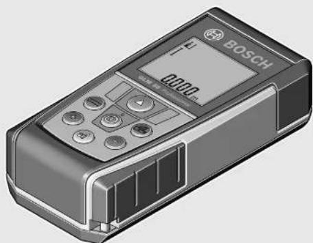
The measuring tool is provided with a warning label (marked with number 15 in the representation of the measuring tool on the graphics page).
IEC 60825-1:2014
<1mW,635nm
Laserstrahlung
If the text of the warning label is not in your national language, stick the provided warning label in your national language over it before operating for the first time.
Do not direct the laser beam at persons or animals and do not stare into the direct or reflected laser beam yourself, not even from a distance. You could blind somebody, cause accidents or damage your eyes.
If laser radiation strikes your eye, you must deliberately close your eyes and immediately turn your head away from the beam.
- Do not use the laser viewing glasses as safety goggles. The laser viewing glasses are used for improved visualisation of the laser beam, but they do not protect against laser radiation.
- Do not use the laser viewing glasses as sun glasses or in traffic. The laser viewing glasses do not afford complete UV protection and reduce colour perception.
Do not make any modifications to the laser equipment.
Have the measuring tool repaired only through qualified specialists using original spare parts. This ensures that the safety of the measuring tool is maintained.
Do not allow children to use the laser measuring tool without supervision. They could unintentionally blind other persons or themselves.
Do not operate the measuring tool in explosive environments, such as in the presence of flammable liquids, gases or dusts. Sparks can be created in the measuring tool which may ignite the dust or fumes.
Product Description and Specifications
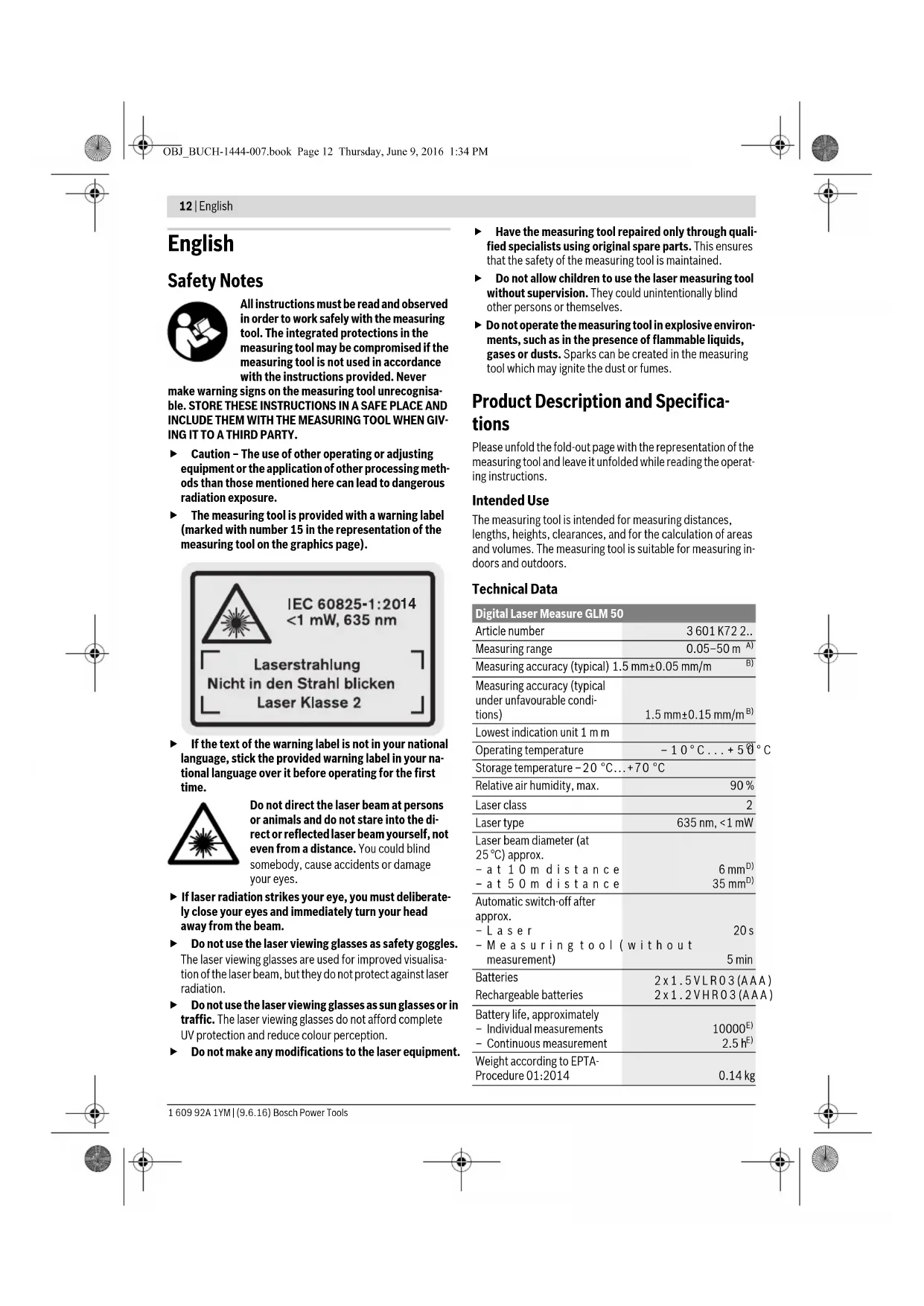
Please unfold the fold-out page with the representation of the measuring tool and leave it unfolded while reading the operating instructions.
Intended Use
The measuring tool is intended for measuring distances, lengths, heights, clearances, and for the calculation of areas and volumes. The measuring tool is suitable for measuring indoors and outdoors.
Technical Data
| Digital Laser Measure GLM 50 | |
| Article number | 3601 K72 2.. |
| Measuring range | 0.05-50 m A) |
| Measuring accuracy (typical) 1.5 mm±0.05 mm/m B) | |
| Measuring accuracy (typical under unfavourable condi- tions) | 1.5 mm±0.15 mm/m B) |
| Lowest indication unit 1 mm | |
| Operating temperature | -10°C...+5°C |
| Storage temperature -20 °C...+70 °C | |
| Relative air humidity, max. | 90 % |
| Laser class | 2 |
| Laser type | 635 nm, <1 mW |
| Laser beam diameter (at 25°C) approx. | |
| - at 10 m distance | 6 mmD) |
| - at 50 m distance | 35 mmD) |
| Automatic switch-off after approx. | |
| - Laser | 20 s |
| - Measuring tool (without measurement) | 5 min |
| Batteries | 2x1.5VLR03 (AAA) |
| Rechargeable batteries | 2x1.2VHR03 (AAA) |
| Battery life, approximately | |
| - Individual measurements | 10000E) |
| - Continuous measurement | 2.5 hE) |
| Weight according to EPTA- Procedure 01:2014 | 0.14 kg |
Digital Laser Measure GLM 50
| Dimensions | 53 x 114 x 30 mm |
| Degree of protection | IP 54 (dust and splash water protected) |
A) The working range increases depending on how well the laser light is reflected from the surface of the target (scattered, not reflective) and with increased brightness of the laser point to the ambient light intensity (interior spaces, twilight). In unfavourable conditions (e.g. when measuring outdoors at intense sunlight), it may be necessary to use the target plate.
B) For measurements from the rear measuring-tool edge. In unfavourable conditions (e.g. at intense sunlight or an insufficiently reflecting surface), a deviation influence of ± 0.15 mm/m must be taken into account. In favourable conditions, a deviation influence of ± 0.05 mm/m must be taken into account.
C) In the continuous measurement function, the maximum operating temperature is +40^ .
D) The width of the laser line depends on the surface characteristics and on the ambient conditions.
E) Less measurements are possible when using 1.2V rechargeable batteries than with 1.5V batteries. The battery life listed refers to measurements without display illumination.
The measuring tool can be clearly identified with the serial number 13 on the type plate.
Product Features
The numbering of the product features shown refers to the illustration of the measuring tool on the graphic page.
1 Display
2 Measuring button
3 Button for area/surface, volume and indirect height measurement (Pythagoras)
4 Delete / On/Off button*
5 Minus button
6 Button for selection of the reference level
7 Fixture for carrying strap
8 Plus button
9 Length and continuous measurement button
0 Battery lid
11 Laser beam outlet
12 Reception lens
13 Serial number
14 1/4" thread
15 Laser warning label
16 Latch of battery lid
17 Protective pouch
18 Tripod
19 Laser viewing glasses
20 Laser target plate*
- The accessories illustrated or described are not included as standard delivery.
"Keep button pressed to call up the extended functions.
Display Elements
a Measured-value lines
b Result line
c Measuring functions
I
Length measurement
↑
Continuous measurement
Area/surface measurement
Volume measurement
Simple Pythagoras Measurement
d Laser, switched on
e Measurement reference level
f Temperature warning
g Battery low indicator
h "ERROR" indication
Assembly
Inserting/Replacing the Batteries
Using alkali-manganese or rechargeable batteries is recommended for operation of the measuring tool.
Less measurements are possible when using 1.2 V rechargeable batteries than with 1.5 V batteries.
To open the battery lid 10, press the latch 16 and remove the battery lid. Insert the batteries/rechargeable batteries. When inserting, pay attention to the correct polarity according to the representation on the inside of the battery compartment.
When inserting the batteries/rechargeable batteries, pay attention to the correct polarity according to the representation on the inside of the battery compartment.
When the battery symbol appears for the first time on the display, at least 100 individual measurements are still possible. The continuous measurement mode is deactivated.
When the battery symbol flashes, the batteries/rechargeable batteries must be replaced. Measurements are no longer possible.
Always replace all batteries/rechargeable batteries at the same time. Do not use different brands or types of batteries/rechargeable batteries together.
Remove the batteries/rechargeable batteries from the measuring tool when not using it for longer periods.
When storing for longer periods, the batteries/rechargeable batteries can corrode and self-discharge.
14|English
Operation
Initial Operation
Do not leave the switched-on measuring tool unattended and switch the measuring tool off after use. Other persons could be blinded by the laser beam.
Protect the measuring tool against moisture and direct sun light.
Do not subject the measuring tool to extreme temperatures or variations in temperature. As an example, do not leave it in vehicles for a long time. In case of large variations in temperature, allow the measuring tool to adjust to the ambient temperature before putting it into operation. In case of extreme temperatures or variations in temperature, the accuracy of the measuring tool can be impaired.
- Avoid heavy impact to or falling down of the measuring tool. After severe exterior effects to the measuring tool, it is recommended to carry out an accuracy check (see "Accuracy Check of the Distance Measurement", page 16) each time before continuing to work.
Switching On and Off
For switching on the measuring tool, the following possibilities are given:
- Pressing the On/Off button 4: The measuring tool is switched on and is in length measurement mode. The laser is not activated.
- Pressing the measuring button 2: Measuring tool and laser are switched on. The measuring tool is in length measurement mode.
Do not point the laser beam at persons or animals and do not look into the laser beam yourself, not even from a large distance.
To switch off the measuring tool, press the On/Off button 4 for a few seconds.
When no button on the measuring tool is pressed for approx. 5 minutes, the measuring tool automatically switches off to save the batteries.
Measuring Procedure
After switching on by pressing the measuring button 2, the measuring tool is always in length measurement mode. Other measuring modes can be switched to by pressing the respective function/mode button (see "Measuring Functions", page 14).
After switching on, the rear edge of the measuring tool is preset as the reference level for the measurement. By pressing the reference level button 6, the reference level can be changed (see "Selecting the Reference Level (see figure A)", page 14).
Place the measuring tool with the selected reference plane against the desired starting point of the measurement (e.g. a wall).
Briefly press the measuring button 2 to switch on the laser beam.
Do not point the laser beam at persons or animals and do not look into the laser beam yourself, not even from a large distance.
Aim the laser beam at the target surface. Briefly press the measuring button 2 again to initiate the measurement. In the continuous measurement mode, the measurement begins immediately upon switching on the function.
Typically, the measured value appears after 0.5 seconds and latest after 4 seconds. The duration of the measurement depends on the distance, the light conditions and the reflection properties of the target surface. The laser beam is switched off automatically upon completion of the measurement.
When no measurement has taken place approx. 20 seconds after sighting, the laser beam is switched off automatically to save the batteries.
Selecting the Reference Level (see figure A)
For the measurement, you can select between three different reference planes:
- the rear measuring-tool edge (e.g. when measuring on ward from a wall),
- the front measuring-tool edge (e.g. when measuring on- ward from a table edge),
- The centre of thread 14 (e.g. for tripod measurements).
To select the reference level, press button 6 until the requested reference level is indicated on the display. Each time after switching on the measuring tool, the rear end of the measuring tool is preset as the reference level.
Display Illumination
The display illumination is automatically activated, depending on the ambient brightness. When no button is pressed after the display illumination switches on, it is dimmed to save the batteries.
Measuring Functions
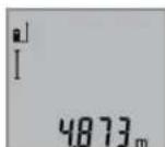
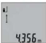
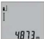
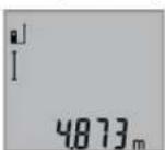
Simple Length Measurement (see figure B)
For length measurements, press button 9 until the "length measurement" indication appears on the display.
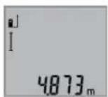
To switch the laser on and for measuring, briefly press the measuring button 2 once each time.
The measured value is displayed in the result line b.
For several subsequent length measurements, the last measured results are displayed in the measured-value lines a.
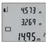
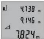
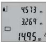
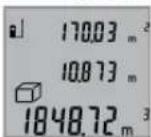
Area Measurement (see figure C)
For area/surface measurements, press button 3 until the indicator for area/surface measurement appears on the display.
Afterwards, measure the length and the width, one after another, in the same manner as a length measurement. The laser beam remains switched on between both measurements.

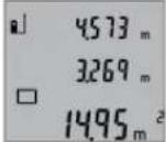
Upon completion of the second measurement, the surface is automatically calculated and displayed in the result line b. The individual measured values are displayed in the measured-value lines a.
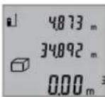
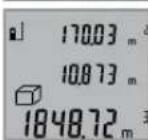
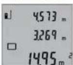
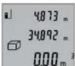
Volume Measurement (see figure D)
For volume measurements, press button 3 until the indicator for volume measurement appears on the display.

Afterwards, measure the length, width and the height, one after another, in the same manner as for a length measurement. The laser beam remains switched on between all three measurements.
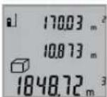
Upon completion of the third measurement, the volume is automatically calculated and displayed in the result line b. The individual measured values are displayed in the measured-value lines a.
Values above 999999m^3 cannot be indicated; "ERROR" appears on the display. Divide the volume to be measured into individual measurements; their values can then be calculated separately and then summarized.
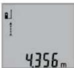
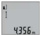
Continuous Measurement (Tracking) (see figure E)
For continuous measurements, the measuring tool can be moved relative to the target, whereby the measuring value is updated approx. every 0.5 seconds. In this manner, as an example, you can move a certain distance away from a wall, while the actual distance can always be read.
For continuous measurements, press button 9 until the indicator for continuous measurement appears on the display. To start the continuous measurement, press the measuring button 2.
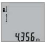
The current measured value is displayed in the result line b.
Pressing the measuring button 2 ends the continuous measurement. The last measured value is displayed in the result line b. Pressing the measuring button 2 again restarts a continuous measuring run.
Continuous measurement automatically switches off after 5 min. The last measured value remains indicated in the result line b.
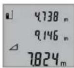
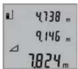
Indirect height measurement / Simple Pythagoras Measurement (see figure F)
The indirect height measurement is used to measure distances that cannot be measured directly because an obstacle would obstruct the laser beam or no target surface is available as a reflector. Correct results are achieved only when the right angles required for the respective measurement are exactly adhered to (Pythagorean Theorem).
Pay attention that the reference plane of the measurement (e.g. the rear edge of the measuring tool) remains exactly at the same location for all individual measurements within a measuring sequence.
The laser beam remains switched on between the individual measurements.
Press button 3 until the indication for simple Pythagoras measurement appears on the display.
Measure distances "1" and "2" in this sequence as for a length measurement. Pay attention that a right angle exists between distance "1" and the sought distance "X".
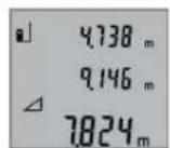
Upon completion of the last measurement, the result for the sought distance "X" is displayed in the result line b. The individual measured values are displayed in the measured-value lines a.
Deleting Measured Values
Briefly pressing button 4 deletes the last individual measuring value determined in all measuring functions. Briefly pressing the button repeatedly deletes the individual measured values in reverse order.
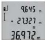
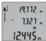
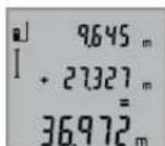
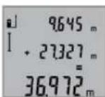
Adding Measured Values
To add measuring values, firstly carry out a measurement. Then press the plus button 8.For confirmation, " + " appears on the display.
To add volumes or areas/surfaces, press the plus button 8 after the first completed measuring process. For confirmation,
^ + appears on the display left of the volume/area symbol. Then carry out a second measurement.
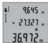
To call up the sum of both measurements, press the plus button 8 again. The calculation is indicated in the measured-value lines a, and the sum in the result line b.
After calculation of the sum, further measured values can be added to this result when pressing the plus button 8 prior to each measurement.
Notes on the addition:
-
Mixed length, area/surface and volume values cannot be added together. For example, when a length and area value are added, "ERROR" briefly appears on the display after pressing the plus button 8. Afterwards, the measuring tool switches back to the last active measuring mode.
-
For each calculation, the result of one measurement is added (e.g. the volume value); for continuous measurements, this would be the displayed measured value in result line b. The addition of individual measured values from the measured-value lines a is not possible.
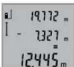
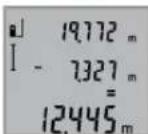
Subtracting Measured Values
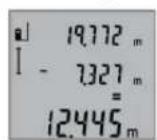
To subtract measuring values, press minus button 5; For confirmation, " - " is indicated on the display. The further procedure is analog to "Adding Measured Values".
Working Advice
General Information
The reception lens 12 and the laser beam outlet 11 must not be covered when taking a measurement.
The measuring tool must not be moved while taking a measurement (with the exception of the continuous measurement
16|English
function). Therefore, place the measuring tool, as far as this is possible, against or on a firm stop or supporting surface.
Influence Effects on the Measuring Range
The measuring range depends upon the light conditions and the reflection properties of the target surface. For improved visibility of the laser beam when working outdoors and when the sunlight is intense, use the laser viewing glasses 19 (accessory) and the laser target plate 20 (accessory), or shade off the target surface.
Influence Effects on the Measuring Result
Due to physical effects, faulty measurements cannot be excluded when measuring on different surfaces. Included here are:
- Transparent surfaces (e.g., glass, water),
- Reflecting surfaces (e.g., polished metal, glass),
- Porous surfaces (e.g. insulation materials),
- Structured surfaces (e.g., roughcast, natural stone).
If required, use the laser target plate 20 (accessory) on these surfaces.
Furthermore, faulty measurements are also possible when sighting inclined target surfaces.
Also, air layers with varying temperatures or indirectly received reflections can affect the measured value.
Accuracy Check of the Distance Measurement
The accuracy of the distance measurement can be checked as follows:
- Select a permanently unchangeable measuring section with a length of approx. 1 to 10 metres; its length must be precisely known (e.g. the width of a room or a door opening). The measuring distance must be indoors; the target surface for the measurement must be smooth and reflect well.
- Measure the distance 10 in The deviation of the individual measurements from the mean value must not exceed ± 2mm (max.). Log the measurements, so that you can compare their accuracy at a later point of time.
Working with the Tripod (Accessory)
The use of a tripod is particularly necessary for larger distances. Position the measuring tool with the 1/4'' thread 14 onto the quick-change plate of the tripod 18 or a commercially available camera tripod. Tighten the measuring tool with the locking screw of the quick-change plate.
Set the corresponding reference level for measurement with a tripod by pushing button 6 (the reference level is the thread).
Troubleshooting - Causes and Corrective Measures
Cause Corrective Measure
Temperature warning indicator (f) flashing; measurement not possible
The measuring tool is outside the Wait until the measuring operating temperature range from tool has reached the op- 10^ to +50^ (in the erating temperature ous measurement function up to +40^ ).
"ERROR" indication in the display
Addition/Subtraction of measured values with different units of measure Only add/subtract measured values with the same units of measure
The angle between the laser beam and the target is too acute.
Enlarge the angle between the laser beam and the target
The target surface reflects too intensely (e.g. a mirror) or insufficiently (e.g. black fabric), or the ambient light is too bright.
The laser beam outlet 11 or the re- Wipe the laser beam outception lens 12 are misted up let 11 and/or the recep (e.g. due to a rapid temperature tion lens 12 dry using a change). soft cloth
Calculated value is greater than Divide calculation into 999999 m/m²/m³. intermediate steps
Measuring result not plausible
The target surface does not reflect Cover off the target sur-correctly (e.g. water, glass). face
This case is an outlet 11 or the re- ception lens 12 are covered. Make sure that the laser beam outlet 11 or thereception lens 12 are un- obstructed
Wrong reference level set Select reference level that corresponds to measurement
Obstruction in path of laser beam Laser point must be completely on target surface.
The indication remains unchanged or the measuring tool reacts unexpectedly after pressing a button
Software error Remove the batteries
and start the measuring tool again after reinserting them.
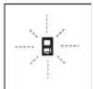
The measuring tool monitors the correct function for each measurement. When a defect is determined, only the symbol shown aside flashes in the display. In this case, or when the above mentioned corrective measures cannot correct an error, have the measuring tool checked by an after-sales service agent for Bosch power tools.
Maintenance and Service
Maintenance and Cleaning
Store and transport the measuring tool only in the supplied protective pouch.
Keep the measuring tool clean at all times.
Do not immerse the measuring tool in water or other fluids. Wipe off debris using a moist and soft cloth. Do not use any cleaning agents or solvents.
Maintain the reception lens 12 in particular, with the same care as required for eye glasses or the lens of a camera.
If the measuring tool should fail despite the care taken in manufacturing and testing procedures, repair should be carried out by an authorised after-sales service centre for Bosch power tools. Do not open the measuring tool yourself.
In case of repairs, send in the measuring tool packed in its protective pouch 17.
After-sales Service and Application Service
Our after-sales service responds to your questions concerning maintenance and repair of your product as well as spare parts. Exploded views and information on spare parts can also be found under:
www.bosch-pt.com
Bosch's application service team will gladly answer questions concerning our products and their accessories.
In all correspondence and spare parts orders, please always include the 10-digit article number given on the nameplate of the product.
Great Britain
Robert Bosch Ltd. (B.S.C.)
P.O.Box 98
Broadwater Park
North Orbital Road
Denham
Uxbridge
UB95HJ
At www.bosch-pt.co.uk you can order spare parts or arrange the collection of a product in need of servicing or repair.
Tel. Service: (0344) 7360109
E-Mail: boschservicecentre@bosch.com
Ireland
Origo Ltd.
Unit 23 Magna Drive
Magna Business Park
City West
Dublin 24
Tel. Service: (01) 4666700
Fax: (01) 4666888
Australia, New Zealand and Pacific Islands
Robert Bosch Australia Pty. Ltd.
Power Tools
Locked Bag 66
Clayton South VIC 3169
Customer Contact Center
Inside Australia:
Phone: (01300) 307044
Fax: (01300) 307045
Inside New Zealand:
Phone: (0800) 543353
Fax: (0800) 428570
Outside AU and NZ:
Phone: +61 395415555
www.bosch.com.au
Republic of South Africa
Customer service
Hotline: (011) 6519600
Gauteng - BSC Service Centre
35 Roper Street, New Centre
Johannesburg
Tel.: (011) 4939375
Fax: (011) 4930126
E-Mail: bsctools@icon.co.za
KZN - BSC Service Centre
Unit E, Almar Centre
143 Crompton Street
Pinetown
Tel.: (031) 7012120
Fax: (031) 7012446
E-Mail: bsc.dur@za.bosch.com
Western Cape - BSC Service Centre
Democracy Way, Prosperity Park
Milnerton
Tel.: (021) 5512577
Fax: (021) 5513223
E-Mail: bsc@zsd.co.za
Bosch Headquarters
Midrand, Gauteng
Tel.: (011) 6519600
Fax: (011) 6519880
E-Mail: rbsa-hq.pts@za.bosch.com
Disposal
Measuring tools, accessories and packaging should be sorted
for environmental-friendly recycling.
Do not dispose of measuring tools and batteries/rechargea
ble batteries into household waste!
18 | Français
Only for EC countries:
According to the European Guideline 2012/19/EU, measuring tools that are no longer usable, and according to the European Guideline 2006/66/EC, defective or used battery packs/batteries, must be collected separately and disposed of in an environmentally correct manner.
Battery packs/batteries no longer suitable for use can be directly returned at:
Great Britain
Robert Bosch Ltd. (B.S.C.)
P.O.Box 98
Broadwater Park
North Orbital Road
Denham
Uxbridge
UB95HJ
At www.bosch-pt.co.uk you can order spare parts or arrange
the collection of a product in need of servicing or repair.
Tel. Service: (0344) 7360109
E-Mail: boschservicecentre@bosch.com
Subject to change without notice.
François
Mesure continue (voir figure E)
Robert Bosch (France) S.A.S.
Se先进技术, in particular, are the following:
Ret社会各界 and the public to see the new film. The movie will be directed by the producer, who will be responsible for the production of the film.
Ret lasersträden mod molefladen. Malingen uldöses vedigen kort at trykke pa tasten maling 2.
I Funktionen konstant maling starter malingen, sa snart fungktonen taendes.
Mälevaerdien fremkommertypisklobetaf0,5sogensestfter4s.Malingensvarighedafhangerafafstandentilmalefladen,lysforholdene ogrefleksionsegenskabernevedmalefladen.Narmalingenerfaerdig,slukkeslaserstralenautomatisk.
Udfores der icke nogen maling ca. 20 s after at stralen retet mod malet, slukker laserstralen automatisk for at skane batterierne.
Vaelg referencingeniveau (se Fig. A)
Bosch Service Center
Telegrafvej 3
2750 Ballerup
Pawww.bosch-pt.dkkanderonlinebestillesreservedeleller oprettes en reparations ordre.
TIf. Service Center: 44898855
Fax:44898755
E-Mail: vaerktoej@dk.bosch.com
Bortskaffelse
Bosch Service Center
Telegrafvej 3
2750 Ballerup
Danmark
Tel.: (08) 7501820 (inom Sverige)
Fax: (011) 187691
Avfallshantering
XpnooupwaueTovnpoopopo
Toepyaleio metponnc npooipctai yia n metponan aoatae w,uynw uawkai diaonpatw kaohc kai yia tv unoloyi o enapaveiw kai oykw. Eivai katalnao yi metpnoic kai oe eowtepiouc kai oe eXtwepikouc xwpouc.
Euvtnpnon kal Service
Suvtnpnoan kkaqapiaooc
Na diaquadyete kai va metapepe to epyaieio metponc povo meo otyn npootateutikn Tovto nou to ouvoeui.
Na diatnpieTo epyaleo etponoc navra kaapo.
Mn BuioeTo epyaleo meponoc o evpo n o aaaa uypa.
Kaapietuovpounockaibpwueicu'evauypo,maakotaivi.MnxpnooioiteeagaaKaapiaou n diautec.
Na nepinoieiote ibialtepa to paKo Aynnc 12 pe Tnv Ibia npoeKTkoTnta nou nepinoieiote ta yuaia daac kai/n Tn foToypapikn oac mynavn.
Av,nap' oae tic enmuanevec meoobouc kataoekunkai eEyyou, to epyaieio eptponoc otapatneia kanto va letoupyei, tote n eniokun tou npenei va avateoe i eva eoouodotnevo aupeyio ia aektpika epaiaia Tc Bosch. Mny aovilee o idioc/n ibia to epaiaio eptponoc.
Toepyaeioeipno npeneva anooteaia yia emakeunpeaa npootateutiktoavta17.
Service kal npoxn ououauxphng
To Service anavtacipewthoeicocxetika pe tnv enokueh kai tn auvtpon Tou npoiobocacKaowc yia ta katalnaa avatallaakta:
www.bosch-pt.com
H ouàna npoxnç ouβouawv tnc Bosch anavra euxapiotoc otic epwthnoeic oac oxetiká μa Ta npoiovta mac kai avtalakKTiKa Touc.
△wote o aeC Tc epwtnoic kai npayyelaieavtaaaktwv onoosnnot to 10ynio Kwoikok apiOo uopovaeTnivkiba tunou tou npoiovtoc.
EAAaδg
Robert Bosch A.E.
Epxelac 37
19400Kopwni-Aθηγα
Tnλ:2105701258
ΦaE:2105701283
www.bosch.com
www.bosch-pt.gr
ABZ Service A.E.
Tnλ:2105701380
Φaξ: 2105701607
Anoupon
Taepyaleiaeponanc. Taepaetaata kai ouokueuaalec npenei va avakukawovtai pe tropo piooc to nepiaalov.
Mny pfe Ta epyaleia metponc kai tic natapiec ota anopipmuata Tou oniou oac!
Movi yia xwpec tnc EE:
Uppwa uTn Koivotik Obyla
2012/19/EE ta axpota epyaiaeia tprn
onc, kai omuwva u Tn Koivotik Obyla
2006/66/EK oXaaogvec n avawvec
muatapec 6ev elvai naov unoxpewtko va
oulayovtaiexwpiotyia vavakukawoov
u pe tropo fko npoc to nepiabauov.
Tnpoue to 6ikaiwa aalayov.
Türkce
Güvenlik Talimatu

Robert Bosch Sp. z o.o.
Bosch Service Center PT
K Vapence 1621/16
692 01 Mikulov
Na www.bosch-pt.cz si si muzete objednat opravu Vaseho stroje nebo nahradni dily online.
Tel.: 519305700
Fax: 519305705
E-Mail: servis.naradi@cz.bosch.com
www.bosch.cz
Zprcovani odpadu
Merici pristroje, prisluosenstvi a obaly by melyb't dodany k opetovnemu zhdnocen neposkozujcim zuivotni prostrejd.
Data n3roTOBHeHryka3Ha Ha NoCleHeNcTpaHnue 06IOKKnPykoBOCTBa Hn Ha Kopnyce H3dEInH.
KoHTaKTHa HnΦOpMaun OTHOHmnpTepa coepKHTcHa ynaKOBKe.
Cpok cnky6bln3dennna
Cpok Cnyk6bI H3dEHHncoCTabHnet 7 net. He peKoMeHdyetcK 3KcNpyataun no HcTeueHHn 5 net xpaHeHH nTaTbI n3rOToBnEHn 6e3 npedBaHPtehHO npOBepKn (aTy n3rTOBnEHn CM. Ha 3TNKeTke).
IpeuehB KpHTnueckHX OTka3OB H OuH6Ouyhle DeCTBna nepcohana Hnn NOnb3OBaTeTn
-HeHCIOJIb3OBA Tb Pn IOBNEHIN DblMa HeIOCPeCTBeHHOI3KOpNycaH3dEINr
-HeHCIOB3OBAbHaOTKpbITOMIPOCTpaHCTBeBOBpEm DOXJRA(BpaCnblAReMoBOe)
-He BKNIOHATb npn nonaHaHH BOdbI B KOpNc
Kpntepnn npedenbhbix coctoHHN
NOBpeKdEN KOpnyc H3dennr
TnH n nepnoaohocb texnueckoro o6cnyXHBaHH
PekomeHcyTcOuHCTb HnCTpyMeHrOT NbINN NOcNe KaJIO TOHCNOB3OBAHNA.
Xpahenne
- Heo6xOdHMo XpaHHTb B CYXOM MeCTe
HeoXOJMO XpaHnB BdAnOT NCTOCHNKOB NOBbIeHHbIX TEMpePAty IN BO3DeNCTBnCOnHehBX Nyey - npn xpaHEnH HeobxOdHMo H3beraTb pe3KOro nepenada Temnepatyp
-eCNHnCTpyMeHT NoCTabIeTcB MmKo CymKe HnPiactKOBOOM KeCe peKOMeHyETcXpaHnTB nHCTpyMeHT B3ToH 3aunTHO yNaKOBke - noDpObHbIe Tpe6oBaHnK yCIOBnM XpaHeHHc MOrTpHte BTOCT 15150 (YcNoBne 1)
TpaHcnOpTHpoBka
KaTeROpHueeCKn He DonycKaeTcra NaJeHne H NIObIe MExaHNueckNe BO3dEJICTBnHa yNaKOBky npu TpaHCnOpTHPOBKe
- npn pa3rpy3ke/nporpy3ke He donyckaetc HcnoIb30BaHne IIO6oO BnDa texHnK,pa6oTaoueH NO npHnHny 3aXnMa yNaKOBKn
noDpObHbIe Tpe6oBaHnK yCIOBnAM TpaHCnOpTHPOBKn CMOTPte BTOCT 15150 (yCIOBne 5)
Yka3aHn no 6e3onachoctn

Ira oecneueHn 6eonacHn Hndex-Ho pa60tbc n3MepeHtebHbIM HnCTpyMEHOTm DOJIxHbI 6bIt npouHTaHb I CO6IOaTbCBA HnCTpyKun. HcNoB3ObaHHe n3MepeTebHOrO HnCTpyMeHTA He B COOTBetCTBnC HactoUHM yka3AHNM
YpeBaTo NOBpExdHn HNTERPpObaHHbX 3aUHTbIX Me- XAH3MOB. HNKOrDa He N3MeHnIe Do Hey3HABAeMOCTH npeDynpedTbHbIe Ta6NHcKn Ha N3MepeTbHOM HNCTpyMeTe. XOPOJO COxPAHrIe 3Ty HNCTpyKUIO HNEPEDABAHTE EE BMECTe C PNEPEDAUY E N3ME- PNTebHOrO NHCTPYMEHTA.
BHIMAHHE-NCNONb3OBAHNEpyrHexyONMAHYtbIX 3dec3neMeHTOBynpaBHeHHpeRyNpOBaHHnDpyrHX MeTOOB 3KcPnIyatauHH MoKET NOBeprHyTB Bac onachomy dA 3dOpOBb H3nyeHIO.
H3MepHTeBbHb HnCTpyMeH nOCTaBnTcA C npEynpdnteBHO TabnKo (Ha ctpaHnce c H3o6paXeHHem H3MepHTeBHO HOCTpyMeHt aNOKa3Ha NOD HoMEpOM 15).

EcHn TeKCT npdUnpeHnteBhoT TaBnueKn He Ha 3bKe BaWe cTpaHb, 3akneTe erO nepe nepBoN 3KcNpyataueH npnaraemn HAKJeNKo Ha 3bike BaWe cTpaHb.
He hanaBnTe nyu na3epa Ha nIOeHnnXHBTObHx n Camn He CMOTpHte HnpAHOHn OTPKaemblnyu na3epa.3ToTnyu MoKET cIeNHTb NIOe,CTaTb npHHoH HeCuaCTHO CNYaARNNOBpeNTb rna.
B cnyae nonaahanna naephoro nyua B rna 3na3a hyxho HamepeHHO 3akpbItb HemeJeHHO OTBepyTbCraOTnya.
He npmeHnTe NaepHbte OOKB KaueCTBe 3aunThbIX ouKOB. NaepHbte ouKn cnykat dnyuWero paCno3HaBaHnnaapeHOrO Lyua, Ondako OH He 3aunuAOT ot naepHO HOIyueHn.
He npHmehnTe na3ephble ouKn b KaueCTbe conHeHybIX OOKOB HIN B yNCHHom DBNXeHH. Na3epHble ouKn He daIOT NIOHO 3aunTbI OT yNbTpapHoneTOBoro HnyeHHN IyyduaHOT BOCpnpAHTne KpacOK.
He mehaTe HnueRo BnaePhoM yctpoiCTBe.


Pemont BaWero H3MepHTeBHO HOHCTpyMeHaTo npuyaTe TOnbKO KBaHNHcHPOBaHHOMy NepcoHany,NCNoB3yTOnbKO OpRnHaBbHbe 3aNaCHBe YaCTn.3TNMO6ecneuBaETc 6e3oNaCHOCTb H3MepHTeBHO HOHCTpyMeHaTa.
He pasewaiTe DeTAM NOB3OBaTBcra NaeepbHIM H3MePnTebHbIM HNCTpyMeHToM 6e3 Ha3Opa. OHMOrTy He-ymblIeHNO OCLENITb IIOJe.
He pa6oatae cn3mepehtenbHbIM HnctpymehTOM Bo B3pbBOONACHOpe, no6n3OCTN OTROPQHXKIOKOte,ra3OBnblIN. Bn3MepeHTeBHom HnctpymTe MOrTy 06pa3OBaTBcHCKpbl,OT KOTOpBX MoKeT BOCIIIaMeHHTCBnIbHnnapbl.
Pycckn103
19 OuknIpa60TbI cIa3epHbIM HHTpyMeHToM
20ВизИрнай Марка*
*N3o6paXeHHbIe HIN ONHcAHbIe pHnHaJnxHoCTH He BXOaT B CTaHapThbI KOMnNEKT NoCTaBKn.
**IINBbI3OBA DOONHHTenbHbIX FyHKuH DEPKNTE KHOKNY HAXaTOn.
3JeMeHtbl HnDkaCnn
aN3mepenHHbe 3NaueHn
B Pe3ynbTaT
CpeKIMbI N3MepeHnIa
T 3mepeHne dnnhbl
PpoDOnXnTeNbHbHe H3MepeHHa
U3mepeHne nloaann
N3mepenHe o6bema
PpocToe H3mepenno TeopemnHparopa
d Na3ep BkIoueH
e NIOCKOCTb OTCUeta npn H3MepeHH
fHnKaTOp BbXoDa 3a npedeBbl DOnyCTHMOrToemnpaTpyHOrO nnAna30Ha
gPpeDynpEckdeneHoepa3pAke6aTaapeek
HnDnKaTOp OwN6Kn «ERROR»
C6opka
YctahOBka/3aMeHa 6atapeek
B H3MePHTeHbHom HcTpyMeHe peKoMeHdyETc HcNoIb30BaTb ⅡeNoUHO-MapraHcEbbie 6aTapeNn HnAkkymyIaTOpHbIe 6aTapeN.
CakymyIopmbHm6batapeamHa1,2BBo3MOxHO MeHb- Wn3mepeHH, yem c 6aatapekamHa 1,5 B.
YtO6bI OTKpBtB KpbIky 6batapeHoro OTceKa 10, HAKMHTe
fHKcTOp 16 H CHMHTe KpbIky 6batapeHoro OTceKa.
BCTaBbTe 6aTapeKn HnNn AkkyMnyTOpHbIe 6aTapeN. CneJnte 3a npabNbHoN NpIyRHOCTbIO B COOTBeTcBn C H3O6paKeHHem Ha BHTpeHHe CTOpOHe KpbUkN 6aTapeHOro OTCeka.
Pn yctaHOBke 6atapeek/akkyMnyTOphBx 6batapee CneIHTe 3a npabNbHO HnpaBHeHcOtbo NIOIOcOB B COOTBETCTBn C H306paxKeHHem BHytpn 6batapeHOro OTCeka.
Iocne nepBOrO noRnBHeHn Ha dncInee cMbOna 6atapeeK BO3MOxHO eue MHN.100 H3MepeHn. FyHKuN pOdoJXHTeNBHO HO3MepeHn OTKnIOUeHa.
Ecn CmB0n 6aTapeek MnaeT, Bbl DOnJXhbl 3aMeHHTb 6a- TapeKn/AkKMyNtOpHbte 3neMeHTbl. PpOOnJxHeHn E3mepeHn 6oee HeBO3MOxHO.
Bcerda3aemeHnTe Bce 6atapeKn/AKKymnTOpHbIe 6atape ONDOBpeMeHHo. Ncnonb3yIte TOnbKO 6atapeKn/AKKymnTOpHbIe 6atape OndHO rpoN3BOHTeJI IN COnHaKOB0E MKOCTbIO.
BbHMaTe 6aTapeKn/AKKyMnyTopHbE 6aTapeHn H3MepeHtBHorO HHCTpyMeNTa,ecN BblnteHbHoe BpemHe 6yDteeroHCNOB3oBaTb. PnINHTbHom XpaHeHH BO3MOKHa Kopp03n Hn Camopap3paKa 6batapeek/AKKyMnyTophix 6aTapeN.
Pa6ota c HnHcTpymeHTOM
3Kcnnyataa
He octabnIte 6e3 npcMoTa BkIOueHbI H3MepeTeBbHbH NHCPTpMeHT N BBKIOuAte ero nocne HCNoB30BaHH. pyrHne Iua MOrTy 6bTb OcnennHbI na3epbHIM NyyOM.
3aunuTe HmepntbHbHn HnctpyMeHT OT Bnarn npmbix cOnHeHbIXnyeH.
He noBepraTe H3MePHTeBbHbHn HnCTpyMeT B03dEnCTBnO 3KCTpeMaIbHbIX TempeaTy n TempeaTyPbIX nepenadOB. B qacTHocN, He octabnre Ero hnnentbHOe BPema BA mAnHe. Pn6BoIbHX nepenaax TempepaTybl Chayana daTe H3MePHTeBHOmy HnCTpyMeHTy cTa6HnHnIPoBaTB CBOHO TempeaTy, npexDe yem HaunHaTbpaboTa b cHm. 3KCTpeMaIbHbIe TempeaTybl TEmpeaTypHbIe nepenadbl MOrY OTRpuAteBnHO BnHrt BaTOOHcTb H3MePHTeBHO rHCTpyMeHTa.
H36eAaTe CnIbHbIX ToUcOB H naDenn H3MePteBbHO HOHCTpyMeNTa. IocLe CnIbHbIX BHEWHNX BO3dEChT Bn Ha H3MePteBbHb INHCTpyMeHT peKoMeHdyETc npoBepntb Eero TOHOCb, IpexJe Yem IpOdoJXkTa b pa60taTb C H3CTpyMeHTOM (CM. «IpOBePKaTOHOCTH H3MepeHna pacctOHHRA, CTp. 107).
BkIIOueHHe/BbIKIOueHHe
ДЯВКIOUeHnI3MEpITeNbHOrO INCHTpMyeHa Bbl MoKeTe: -Hakatb KhoNKy BKIOuateY4: I3MePITeNbHbIn HnCTpyMeHT BKNIOuaeTc HaxoNDTCBpeKIMe I3MepeHnIHyI. Na3ep npI 3OM He BKIOuaeTc.
HaKMMTe KHNkY N3MepeHn2: N3MePteNbHbHn HnCTpyMeHT HnA3ep BKNIOaHO.Tc. N3MePteNbHbHn HnCTpyMeHT HaxoNTcB PexHMe N3MepeHn nnHbI.
HAnpaBnIte na3epHbI NyHa IIOe Hnn XNBOHbIX HcMoTpTe Camh B na3epHbI Nyu, B Tom YNCne nC 6oBsworopacctOHHa.
Iy BIKIOeHn H3MePHTbHOrH NcTpyMeHTa HaKMHTe KHOJky BIKIOeHn 4NepXHTe ee HaxaTo IpoDOnKHe TbeHoe Bpem.
EcnB TceHHe np6n.5MH.Na H3MePHTeNbHOM HNCTpyMeHTe He 6yET HaKIMatbca HNKaKnx KHOJOK, H3MePHTeNBHy INHCTpymeTc eIbO 3KOHOMn 6Taapei abTomaHueckn BbIKIOuayTcA
H3mepenme
Iocne BkIoUeHnHaKaTHem KHOKNu 3MepeHn2 u3MePntbHbIuHCTpyMeHT BCerDa HaxoJITcB pexKHMn 3MepeHn DaHHbI. DpyTne peKHMblu3MepeHnBbMoKeTe HaCtpo

Pycckn|105
Hb HaKaTHeM KHONK COOTBeTCTBHyIOUeTopeXHaMa (cM.
HnH3MepeHHaHnHbHaKHMaTe KHOHKY 9 Do TcNp, NOKa Ha DnCnIe He NoBHTcN HnIKaTOp H3MepeHHaHnHb
ДяВКЛЮЧЕНЯЗЕРANПОБЕДЕНЯ
N3MEPEHннннннннннннн
HA KHOKNK Y3MEPEHIN2.
N3MepeHHoe 3HaueHHe NOBBnEeTCB CTPOKe pe3yNbTaTa b.
PnBbIOnHeHH HeckOblkH NpOJOnKHTeBbHx H3MepeHH Dpyr 3a dpyrom pe3yIbTaTbIOcNeHnx H3MepeHH OTO6paKaIoTcB CtPOkax H3MepeHHbX 3HaueHH a.
H3mepeHne nnoaAn (cm.pnc.C)
HnH3MepeHHnIIOuAaHnKaHMaHTe KhoNky 3 Do Tex nop, nokaHaHnCnlee He NoBHTc HnHnKATOp H3MepeHHnIOuAa-
H3MepeTbE DnHHy HnHHyDpyr 3aDpyrom KaK npH n3MepeHHnDnHH. MeXny o6oHNu H3MepeHnMaepHbN yu ocTaETC BKNIOUeHHbIM.
IIOOKOHuaHHBTOPOH3MepeHHaHa-ueHHe NIOUaHn ABToMaTHueckn paCCuHTbBAeTcN H BbICBeuHbAeTcB CTpOKe pe3yJbTaT a.OTdEnbHbIe H3MepeHHbIe 3HaueHHo OTo6paKaOTcB C Tpo KaX H3MepeHHbIX 3HaueHHa.
H3mepeHne 06bema (cm.pnc.D)
IINH3MEpeHHNObbemaHaxnMaTe KHOKNy 3 Do TcNop, NOKa HAnCnPe He NIOBNTCA HnNKaTOp H3MEpeHHNObbema


Iocne 3tOrO n3MepbTe DnHy, WpHpy H BcOTydpY 3aDpyROM KAK npN n3MepeHHn DnH. Mexdy TpeM N3MepeHHm Na3ePbH JyU OctaTcBKnIOueHHbIM.
IIOOKOHaHH TpeTbeHO3MepeHnO6bE mABOTOMaTHueCKH paccHTbIAeTcH bBICBEuHbAeTCBCTPOKe pe3yNbTaTa b. OTdEBHbHe H3MepeHHbIe 3HaueHn OTO6paKaIoTcB CTPokax H3MepeHHbIX 3HaueHn a.
3HaueHnna, npBbIaHouJne 999 999 M³, He MoryT oTO6paKaTbCn Ha nDCnIe BByCBeUHbAeTc KERRR). Pa3dennrH3MepeMbn O6bEm Ha OTdEhBhie H3MepeHHN, KOToPbIe MoXHO paccHTaTb IOOTdEhBOCTH 3aTeM CLOXHTB.
IpoJIoKHTeBHoE H3MepeHne (cm.phc.E)
Pn npoDOnJXHeBHom H3MepeHnn H3MepeHtBbHnHCTpyMeHTMOxHO nepeBnRaTb OTHocHTbeHo cJIeN, pNn 3ToM H3MepeHHoe 3HaueHne AkyaIHNpyeTc np6n. KaKdIbe 0,5 c.Bb MoKeTe, Hanp., nepeBnRaTbcrO CTehbHa Heo6xoJHmoe paCtOHRHe, AkyaIbHoe paCtOHRHe BcERda OTobpaKaaeTc Ha DCnPee.
Дя npdoJnxTeHbHorO n3MepeHnHaXnMaIte KhoNky 9doTex np, nOKaHaDnCIIe He NoBnTc HnDnKATOp ↑ npdoJnxTeHbHorO n3MepeHn. YTo6bl HaayTaB npdoJnxTeHbHoe n3MepeHne, HaxMnte KhoNky n3MepeHn 2.


106|Pycckn
Teyuee H3MepeHHoe 3HaueHne NOBnE TcR B CTOKe pe3ynbTaTa b.
Hakatne KhoNKn H3MepeHn 2 Bb MoKte IpeBaTb npOONKHeBHO H3MepeHne. IocneHHe H3MepeHoe 3HaueHne NOBnEeTCBCTPOKE pe3yNbTaTa b.
IOBTOHPbIM HaxaTHEM KHOKNI N3MepeHn 2 BblMOKeTe CHOBa HaaytbpOdoNkTeBHOe N3MepeHne.
PpOJONKHTeNbHOe H3MepeHHe aBtOMaTHueCKn BbIKIOuayet Cyaepz5 MNH. PocneHHe H3MepeHHe 3HaueHHe npoJOnKaET BbICBeUHbTaCB BCTPOKe pe3yIbTaTa b.
KocBeHHoe H3MepeHHe BbICOTb/ PpOcToe H3MepeHne no TeOpeme NpaFopa (cm. pnc.F)
Hnnpmoe H3mepeHne BbICOTb CnyKNT DnI H3mepeHH paTcHnn, KOTOpbe HEBO3MOXHO H3MePHTb PnRbIM NITEm, ECIN Ha TpaEKTOHN LyCa CyUeCTBYET PnEANTCTBHe INHET cIeENBOI NOBepxHOCTN, CnyKaUeB KCAeCTBe OtpaKaTeH. IINI ONyEHNE pRaBnBbHX pe3YbTaTOB H3mepeHH IOBEPXHOCTN DOJIKHbHAXOHTBCr TOOH NOI PnRbIM YrIOM (TeOpemaPiFaropa).
CneJeTe 3a Tem, YTO6bI BO BpEmr H3MepeHnpepeHnra ToKa (HaNP., 3aHnK pAIN H3MePteNbHorO INCTpyMeHTa) HaXOHNACb PnR BCEx OTOeNbHbIX H3MepeHnx BO BpEmoNEpaUN H3MepeHn CTOPOHO AODHom N TOM Ke MeCTe.
BnepepbBeMEXyOTdJIbHbIMN3MepeHnMa3epHbI JyOCTaetcBAKIOUeHHbIM.
HaxmMaTe KhoNkY 3 Do Tex Nop, Noka HaDnCnnee He NoBNTc HNDKATOp IpocToRo H3MepenHa No TeOpemI Paaropa
N3MepbTe, KaK N npn H3MepeHH dHInhbl, paCCToHHAe1uN 2B yKa3aHHo NocLeNoBaTeNbHOCTN. CNeNTe 3a TEM, YTO6bIOTpE3OK K1N3MepeHm OTpe3OK XHaXOINHCbIO npnPmblYfOM.
No OKOHauHH NocHeHrO H3MepeHHa pe3yNbTaTnH NCKOMOro OTpe3Ka XOT6paKaAeTCBCTPOKe pe3yNbTaTa b.OTdNbHie N3MepeHHbE 3HaueHHa OT6paKaAOTcBCTPOKAX H3MepeHHbIX 3HaueHHa.
YdaneHHe H3MepeHHbIX 3NaueHn
KopOTKIM HaxaTHeM KHONK 4 Bbl MoKeTe ydaJIb TocJeHne N3MepeHHBe 3HaueHn BO BCex pExmMax. MhorokpatHBIM KOpOTKIM HaxaTHeM KHONK OTdIeNbHbe N3MepeHHBe 3HaueHn ydaJIbHTC B O6paTHoNocJeBOATEbHOCTn.
Cnoxehne H3mepenhhix 3haeHHN
TtObIcNOKHTbN3MepeHHbIe 3HaueHnB, BblONHHe Chaana IIOyO npaepaIIO N3MepeHnR.3aTeMa HAKMITE KHOKky
《NIOC》8.IJIO NOITBEpKJEnHn HAINCNNEe NOBnETCA 一 + + TtObIcNoKHTb3AueHnOBebMa ININ NIOUaDN, HAKMITE
NOCne 3abepeHnNEpBOIN Opeaun H3MepeHnR KHOKny
《NIOC》8.IJIO NOITBEpKJEnHn HANCNNEe NOBnETCA 一 + + CNEBaOT CNMBONA ObEma/NNouaIaI.
BbInonHnTe nocne 3ToRTO BTopyKo onepaunIO N3MepeHHN.
Дя onpaшьанясумьдByxИЗмepeHн HaЖMITE eue pa3 KOnkY«nIOc» 8.Pacuet cmmby OTo6paKaetcB CToPOKaIX3MepeHHbIX 3HaueHn a, cymma OTo6paKaetcB CToPKe pe3yIbTaT a b.
Nocne onpeeneHHc ymmbl K3TOMy pe3ynbTaTy MOxHNO npH6abnTbDpyrHe N3MepeHHbIe 3HaueHHa,ecn KaJdbi pa3 nepeOonepaueHHmepeHH6ydt HaXmAtcbKa KHOnka 《PIOC》8.
Yka3aHHN OTHOCHTeJIbHO CLOXeHnI:
3HaueHnIINHbI,IIIOUaIIn HObEMa HeIb3cMeuNBaTb npn CIOXeHH. EcnH, HApI, cKnAdbIaIOTc 3HaueHn IINHbI NIOUaIaI, To pH HauKATNI KHOJIKN (IIIOc) 8 Ha DnCnIee KOPOTKO NOBnIErCTaERERRR).Pocne 3TOrO n3-MepHTeHbI INHCTpyMeHT Bo3BpaIaETc B npeblNyIe peKMn H3MpeHnIA.
-Пибавлиетс ВсгдраеуьтОДнOrOИзмереня (Hanp..3haueHneOBeMa),aPnIpoDOnKHTenbHom Имерени -Измеренhoe 3haueHne, KOTOpoe OTobpaJxAETcHаДИСПЛEEВ CBTOpe pe3yNbTATA b.CIOxHHe OTdJIbHbIX IN3MepHHbIX 3haueHn,OTobpaKaembIX BCTPOKax IN3MepHHbIX 3haueHn a,HEBO3MOXHO.
BbIHTaHHe N3MepeHbIx 3NaeHn
IINBbHHTAHN H3MepeHHbIX 3HaueHnIHAKMTE KHOKNKy MmHyc5, B KaueCTBE NOITBePjXeHnHA DnCnIeNE NOBnTcN<.NoCleNyUoune DeIcTBnA hAnIoTHHbO npaunm, OIncaHHbIM BaPa3DeE《COnKeHne H3MepeHHbIX 3HaueHn
Yka3aHaHnIO npIpuMeHenHIO
06üne yka3aHHn
PnH3MepeHHHHeB3aKpBbBaTbpneMHyIHH3y12N BixOJNa3epHO H3nyeHH 11.
BoBpMaH3MepeHnHa3MePHTbHbHnHCTpyMeHt Hb3a nepeBnRaTb (3a NCKJIuOeHHeM pEKMn npoDOnKHeNbHOr H3MepeHn).NoTOMy nO Bo3MOxKHOCTn NOIOXnTe H3MePeHn. HnHCTpyMeHt Ha IpOuHoe OCHOBaHHe INn PnCTaBBTeero KnpouHOMy OCHOBaHHIO.
ФakTopbI, BnHIOUe Ha dHaNA3OH H3MepeHHA
Hana30n H3MepeHHa 3aBNCHT OT yCNOBn OCBeueHHn OT
otpaxaHOSe CNOC6HOCTN NOBepxHOCTn CEIN. DnIyUeW
BUNMOCTn Ia3EPHOI Nyu a PnIMeHNrTe BO BPEMa paBoTb
BHe NOMEueHHn IN pni CInbHOM CONHcne Na3epHbIe OOKH 19 (PnHaJNeKHOCTb) IN Bn3nPHyIO MapKy 20 (PnHaJNeKHOCTb) INI 3aTeHNTe Bn3nPHyIO MapKy.
ФakTopbl, BnHIOUHe Ha pe3ynbTaT n3MepeHHN
H3aФn3uecknx 3fpeKTOB He NCKIIOUeHO, YoTo pNn H3MepeHH Ha pa3nnHbIX NOBepXHOCTAX MOYr BO3HNKHYbOuIN6KN H3MepeHH. K TAKHM NOBepXHOCTM OTHOCTcR:
- np o3 pa qHbIe NOBepxHocTH (HaNPmEp, cTeKIO, BOa),
-OTpaxaioune NOBepxHocTHn (HaNPmep,nonipoBaHHbI METaJI,CTEKNIO), - npHCTbe NOBepxHocTu (HaNPmep, n3oIpyIOue MaTePnAbbl),

Pycckn107
-CTpykTpynpoBaHbIe NOBepxHocTH(HaNPmep,nopnctaA ⅢtykaTpyka, npnpOndhKamHeh).
Pn Heo6xOaMnOCTn PnmeHnTe TaTaN XIOBepXHOCTe Bn3nPHyIO Mapky 20 (PnHaIeKHOCTb).
PnKOCmHaBeHeHHHaeBbBO3MOXhblOHN6KN.
Bo3yHbIe cOnc p3a3mHouH TeMnepaTyPOu HnHn HnPrMoE OtpaeHHe TaKx MoTy OTPuCaTeNbHO NOBnAHTb Ha H3-MepaEme 3HaueHne.
IpoBepka ToUHcTHn3MepeHHpaacCTOHHN
UTo6bI npOBepBt ToOHTb H3MepeHnPaPacCToHHa, DeiCTByTE CNeDyUoIMo6pa3OM:
Bb6epHTe HEN3MeHHH OTe30K DnHHOk.1-10M,(Ha npHmep, uHINHA NOMEUHRA, DBePHO rpoema), BENuHKA KOtOPOrO Bam ToHIO hBecTHA. OTe30K DonKeH HaXoHITcBA NOMEUHIN, UeEBAI NOBEPXHOCTb H3MepeHNA DoNJHb 6bTb POBHOn HxopoW OToPaKaTb.
-ИЗмеръе отpe3ok 10 pa3 noДрЯ.
OTKIOHOHe 3auehen OTeIbHbIX H3MepeHHOTcpeHero 3aueHHe HeOJIKHO PpeBbIaTb ± 2 MM.3anpToKoJIpy- Te H3MepeHH, YTO6bI Bb CMOrnPi03Ke CpaBHt ToHocTb.
Pa60a co wtaTHbOM (npHnHaIeXHoCTh)
PpHMeHHe WtATnBa Ooc6eHHo Heo6xOIMo Dn8 60nbux paCCTOHH. YcTaHOBnTE N3MepHTenbHbN HnCTpyMeHT pe360n1/4"14 Ha 6bIcTPOcMeHHyIO nHHTy WtATnBa 18 nHn Ha 06bUHb FOToaannapAthb WtATnB. PpoH No pPNBnHTne HnCTpyMeHT BNTOM K nHnTe WtATnBa.
YCTAHOBITE HCXOANDHYIO NIOCKOCTb (pe36a) INH3MEPeHHN COIHTNBOM, HAKAB HA KHONKY 6.
HencnpabHoctb -PpHnHbI ycTapeHne
PnunHaYcTaPaHHe
Muraet HnHkATOp npEynpExeHmO BbXoJe 3a npE denbl DOnyctHMOro TempepatypHoro dHaana30Ha (f), n3-Mepehne HeBO3MOxHO
| Tempepatya H3MepHTeHbHorO | PódoJdaTb, POKa HN |
| HnCTpyMeNTa HaxoDHTcra 3a npe- | CTpyMeHT He HarpeetC |
| dLenamn pa6oYero dnaNa3OHa | HnH He OXlaDHTcra Do pa- |
| -10°C D0 +50°C (BpejXfKHe) Tempepatbyi | |
| IpoDoJIxHTeHbHorO H3MepHHe | |
| do+40°C). | |
Hdikatop «ERROR» ha dncnnee
EcHn HecMOTpa Ha TuataTeNbHyIpoUeIpyu H3rTOBneHn HNCbTaHnHa 3MepHTeNbHbI INHCTpMeHT BCE-TaKn BbIJeT H3 CTPOR, peMOHT DOnJXHa Ipon3BOiHT bAToPn3HPOBaHHa CepBnCHa MaCTepCKa Ira 3NeKTPoHNCTpMeHTOB Bosch. He BcKpbBaIte CaMoCTOeIbHo 3MepHTeNbHbI INHCTpyMeHT.
Ha pemont OTnpabnne H3MepntelhBn HNCTpyMeH T 3a- uTHOM ueXne 17.
CepBn KOncynbTHpObaHHe Ha npEmdTnc- noIb3OBaHH npOdyKun
CepBnchmaMactepckar OTBETHa Bce Baun Bonpocbi no pemOHTu 06cIyKbAHNo BaWero npOdykTa n no 3aNaCTAM. MoTAtXHbIe ueTeKu HnHΦopMaNo no 3anJaCTM BbHaNdeTe TaKke No aPecy:
www.bosch-pt.com
KoNnKeTbcoTpynHKnOB Bosch, npedocTabnouKoK cyNbTaun HA npedmet nCnObn3oBaHn npOdykun, cydoBolbcnem OTBeHT Ha BCE Baun BOpocbl OTHOCntbHora Hauen npOdykunn H ee npHaadJeckHoTe.
IoxaIyIcTa, BO BceX 3anPocax H 3akazax 3anJacte O6raTeIbHO yka3bIaIte 10-3HaHbI TOBapHbI HOpE ITO 3aBOckO Ta5nUke Hdenn.
DnpernoHa:Pocn,Benapycb,Ka3axCTan,YkpanHa
IapaHTHnHOeOcbnyKbAHHe NpeMOHT 3JIeKTPOHHCTpyMeHTA, C cobIOJeHEm Tpe6oBaHH N HOPM 3rTOBHTEN IPOH3BOyTcH A He TepHToPIN BCEx CTpaH ToNbKO BΦHmEHbIX INH ABTopH3OBaHHbIX CepBnChbIX LcHTpax «Po6ept BoW.
PPEyIPEKJEHNE!McnoIb3oBaHne KOHTpaKaTHO npOdykunonacHO B3cNlyatauun,MOKeT pINBecTN Kyuep6yJnBaWero 3OpOBb.13roTOBHeHne npacnpocTaPahHeNeKOHTpaKaTHOH npOdykUnnpeCneJeYerNo 3aKohyBaMNHNCTpAIBHOM yrONOBHM nopAKe.
Pocchra
yIIOHOMOeHHaN3rTOBHTeMeOpraHn3auHa:
OOO «Po6epT BoW»
BaWytHnckoe Wocce, Bn.24
141400,r.XmKm,MockoBckaa o6n.
Pocn
TeN.: 8 800 100 8007 (aBOHOK no PocCNH 6ecnNaThbI)
E-Mail: info.powertools@ru.bosch.com
POnHyIO nAKtyaIbHyIO HΦopMaIIO O paCnIoNoXeHHN cepBCHbIX cHTPOB INpHMeHBIX NyHKTOB Bbl MoKTe NOyUHTb:
-
H a O Φинальном сатve www.bosch-pt.ru
-
nH6o no Tenefohy cnpaBOuHO - cepBnCHOH cnyk6b Bosch 8 800 100 8007 (3BOHOK no PocCnn6ecnnaTHbI)
Benapycb
a BmmpaHHaayehn
b Pe3ynbTaT
C PeknMn BmipIOBaHHA
I BmipioBaHHIOBKKHH
TpBane BmipBoaHH
BmipioBaHHnlo
BIMiPioBaHnO6'Emy
PpOCTe BmIPIOBaHHaTeOpEMOIOIiparopa
dIa3epyBIMKHyTNH
e Ba3Oba IIIOUHa I npn BmIpioBaHHi
fIINDaTOp BnXoY 3a MexKi TeMnepaTyphoro diana3oHy
gIIndkaTop3apJdxJeHocti6atapeiok
hIndnKaTOp nomnKIn «ERROR»
MoHTaX
BCTABHeHHa/3amHa6atapeHok
Y BnMIPOBaIbHOMy npnndi peKoMeHnycTbcB BnKOpNCToByBaTH NyXHO-MpaRanCeBi 6aTaapeKN a60 akMyNtOpiHi 6aTapei.
3akymyIaTOHMM6aTapeMnHa1,2BMOxHaBkoHaTH MeHHe BmipOBAh,Hk3 6aTapeKamn Ha1,5B.
Uo6 BiKpnTH KPNsKc cekui Dn8 6aTapeOOK 10, HATNCHtB
pikcatop 16 i3HIMtB kpnSku Cekui Dn8 6aTapeOIK.
BCTPOMITb 6aTapeKN ABO akyMnTropHi 6aTapei. CnIkyTe
npu bOmy 3a npabNbHM Po3aWbAHHHm NIOHcIB, Jk ce
noka3aHO BCEpeHNi Cekui Dn8 6aTapeOIK.
PnBCTpOMnHHi 6atapeok/kaymynTOpHnx 6atape 3BaKaIte Ha npabInbHy HanpaBneHictb nonHocib, kU ce noka3aHO B cekui dna 6atapeok.
Pn nepwomy noBneHHaHcNneCMBony 6atapehOK MoKINBO ue MIIMyM 100 BMIPHOBaH. FyHKJr TpNBANO BMMIOBAHH BMMKHeHa.
YkpaHcbka 111
KuOCHMBON6atapeyokMIRac,BN NOBHHI NOMHATN 6atapeHK/akymyntopHi enemeHTN.3diHOBaTH BIMIOBAHH6JIbWeHE MOKNBO.
3aBxH MInHte OndOuacHO Bc6aTapeKn/AkymyIaTOphi 6aTapei. BHKOPNCTOBYte NHe6batapeKn a6o akymyIaTOphi 6aTapei OndHoro Bnpo6HnKa i OndHaKOBoi CMHOCTi.
BnMaTe 6aTapeKn/AkymyIaTOpHi 6aTapei3 BmipBoaIbHorO npnaIy, Akuo Bn TpBaHnIac He 6yTe KOpHCTyBaTHc npnaIaOM. Pn TpBaIOMy 3epiAHHI 6aTapeKn Ta akymyIaTOpHi 6aTapeI MoKytB KopoDyBaTH i camopo3paJkaTncr.
Eknnnyatauaia
Noataokpo60tn
He3aHnAaTeYbIMKHyTHBMMIPoBaNbHHnpnaad 6e3dorany,nicra3akinueHHPO6OTBBMHKaTe BMMIPoBaNbHH npnaad.1HJIOOCbMOxytb6ytn 3acnInIeHIa3epHMnIpomehem.
3axnauTe BmipobanbHn npnaB iD BonrH coHryHnx npomeHIB.
He donyckaite BnHbHa BmipobanbHnn npHnaekctpeMaBnHex TemnepaTp Ta TemnepaTyphnx nepenadib.3okpema, He 3aJnilaIte Horo Ha TpBaNn Yac B MaunHi. JkUO BmipobAhn npNla3a3NaB BnHbBy nepenady Temnpatyp, npuHix BMKATn HOro, daTneHomy CTabiniyBatn CBOIO Temnpatpy. EKCTpeMaBHI TemnpatryTa TemnpatpyH nepenadin MOxyt b NoripuyBaTH TOHcHbBMipobAboHoro npHnady.
YHnKaTe CNbHnx NOtOBxIB Ta naIHnBnMipOBaBHorO npnaady. Picn CHbHNX 30BnHIX BnHBiBa HnMIpOBaBnHn npnaad nepeed noaBWOIO po6oTOIO 3 npnaIOM oob'3KOBO nepebiPeTo TouHCTb po6oTH npnaIy (DnB. «PpeBipka ToHocTi BMIPOBaHH BiCTahI), cTOp.113).
BmKahHa/BmHKaHH
Uo6yBIMKHyTH BmipIOBaNbHn npnad, Bn moKeTe:
HaTNCHTH KHOKNKY BHMKHeHH4: BMMIPOBaJIbHH npnnaB MHKaETbcra Ipepe6yBaC BPEXMI BMMIPBOAHH NOBXHH. Na3ep He BMKaetbcra.
HaHCHtB KHONKY BmIPIOBaHH2: BmIPIOBaIbHH IHCTpymeHT Ta Ia3ep BMKAIoTbcB. BmIPIOBaIbHH IHCTpymeHT nepe6yBaC B peKMI BmIPIOBaHH DOBKNHH.
He cnpmOByTe na3epHn npomihb haIIOe i TBapHH i He dIBITbc y na3epHn npomihb, BKIOUaOuH i 3 BENKOi BiCTahi.
Uo6BUMKHYTHBMIPIOBaHn npnaI,DOBHOHaTCHITbHa KHOKNY BMMKHEHH4.
KpnoTAROM np6n.5XBn.BHne 6yDeta HATNCKyBATH HI HA KNY KHONKY Ha BHMIPIOBAIbHOMY npnaDi, npnaIa, 0o6 3aoaIHTN batae, ABTOMaTHNO BIMKaCTbcRc.
IpoeDypa BmipIOBHaHn
Iicra yBMKHeHHaHTNCKyBaHHaM KHONKN BmipIOBaHHa 2 BmIPIOBaHbHHiHCTpyMeHT 3aBKnI nepe6yBaE b pexmi
BIMipHOBAHHHIOBXKHN. IHINPEXHM BIMIpHOBAHHMOXHA Bn6paTH, HATNCHYBUN HA BiNJNOBIDHY KONKY (INB. «BIMipHOaJIbHI φyHKUII», CTOP. 111).
Bakocti 630BOI pIOUHHN NICnBMKAHn BCTaHOBneHH 3aHnKpA npnaNy. HatncKaOuHn KaONky 630BOI nOUIHH 6,MOXHa NOMIHHTn 63OBY nOUIHH (INB.«Bn6ip 630BOI pIOUHH (INB.MaJ.A)》,CTOp.111).
PnCTABTE BmIPBOBbHn npnaIaO6paHO6a3oBOIO nIOuHOIO do 6aKaHOI NOATKOBOI TOKN BmIPIOBAHHN (Hap.,do CTHN).
U6 yBIMKHyTN IaepHn Ipomihb, KOpOTKHaTNCHTb Ha KHONKY BmipHOBAHH 2.
He cnpMOByTe na3epHn npomihb Ha IIOdei TBapHH i He dHBitbcy na3epHn npomihb, BKNIOaOuH i 3 BENKOI BiCTahi.
Habeitb na3epn npomHb Ha ciboby nobepxno. 3diinCHTH BmipIOBaHH, 1e pa3 KopoTko HATNCHTb Ha KHONKY BMIPIOBaHH 2.
BpeKmI 6e3nepepBHorO BmipIOBaHH BmIPIOBaHH po3noHaetcbiDpa3y niCn yBIMKeHHpeKmY.
Pe3yIbTaT BmIPIOBAAH 3'ABNIEcB 3BnuAHO npOTROM 0,5ceK.,Makc.uepe34 cek.TpBnAicb BmIPIOBAHH 3aJIeKHTb BiD BiCTahi,OCBITHeHH I BiD3ePKeAHOBBAHHH BID qIbBOOI NOBEPXHi. PICNA3AKINHHeHH BmIPIOBAHH na3epHN IpOMIHb ABTOMaTHHO BmNkAcTbCra.
KpnoTpornp6n.20nicnaHabeHnHa nIb BmipOBaHH He 3dINCHOeTbcra,naepHn npOMHb Ia 3aoaDxKeHH 6aTapeoK ABToMAuHO BmNkAcTcBra.
Bn6ip 6a30Boi nnouHH (nHb. Man. A)
PnBbMIPIOBAHHI BnMOKeTe Bn6paTHOdHy 3 Tpbox 6a3OBx nlouH:
-3aHnKpaBMMipBOBaHOroIHCpymeHTy(HaP..,npn npCTabneHHIO CTINH),
- nepedhi kpaBmipioBaIbHoro npnay (HaNP.. npn BmipioBaHHi BiKpao cTOna),
-cepeHnHa p3b6n 14 (Hanp., npH BnMipIOBaHHx i3 tTaTHBOM).
U63MHHT6a0bnyHATNCKyTeHaKONky6do TnXnip, NOKH Ha dncnpe He 3'ABNTcH Heo6xHa 6a0ba nOuHa. KoxHH pa3 nicra BMKAHN B JKOCTi 6a0BOI nOuHHBCTAHOBIOETCB3aHIN Kpa npnaNy.
PiiicbiuyBaHHaHnne
PiDcBiyyBaHHIINCIIHnAkTNByEcTbCABTOMaTHUHO B 3aJIeXHoCTi Bi3OBIHIhBOrCBITNa.IKIOICNBAIBIMKHeHHI NcBiyyBaHHIINCIIHnE He 6yHe HATNCKyBaTHCA KOHa KHOJKA, NiCDBiYBaHHrTyckHc3apAn3aOuaJKeHHB 6aTapeHok.
BmipoiBaIbHI cyHKcii
Ipocte BmipioBaHHIOBxHHN (INB.MaN.B)
IINBHMIPIOBAHHIOBXHHHaTHCKaHTe Ha KHOKNy 9DoTnx nip, NOKH HAnCnPeI He 3'ABNTbC iHNKAtOP BHMIPIOBAHH IOBXHH
112|YkpaHcbka
IyBIMKHeHHnIa3epa Ta BIKOHaHH
BIMIPBOAHHnHaTHCHITb OINHpa3
KOPOTKHO KHONKY BIMIPBOAHH2.
BIMIPHE 3haueHHn3'RAJIeTbcnB Pnky peayntayb.
KIO Bu 3iHcHcTe KeINbKa NocNIOBHNX BmIPIOBAHb IOBKMHN,TO pe3yIbTaTN OCTAHIX BmIPIOBAHb 3'RBNIOTbCn B pKaX BmIPARHX 3HaueHb a.
BmipbAHHHnOoi (Hb.Man.C)
Длгь ВИМIPЮВАнH ПLOОHаТИСКаNTеHa KНONKY3doTINXnip, nOKHnHaДИСПЛeIHe3'ЯВТБССIHДИКATOPBIMIPЮВАнHПLOOJI
Iicna zuoro npomipraTe doBxHHy i uHnHy knpu BmipoBAHHIOBxHH. B nepepBi mIX o6oma BmipoBaHHaMn Ia3epHNI pOMIHb 3aHnAactbcra YbIMKHYTNM.
Iicna3akinueHHdpyrTOBmipioBaHH 3aueHHnnoi aBtOMaTHUo BpaxoByc6i 3'ABNIEbC8B pkype- 3yntbyb. Okpei 3aueHHBmipioBAHH 3'ABNIOBcB pKkAaBnBmipraHx 3aueHb a.
BmipiobaHHo6'cMy (nB. man.D)
IINBIMIPIOBAHHO6EMHYATNCKAHTe HAKHONIKY3doTHNXnip, NOKHHaHNCIIeHE3'RBNTbCIAHDKaTOP BIMIPIOBAHHO6EMy
Iicra yboRBO BmipraTe DOBxHHy,
WnPHHy IBcOTy,IK i npn BmipIOBaHHIOBxHH. B nepepbIMKtpbOMa HMIPOBAHHMaNnaepHnPiPOMHb 3aIIuHaTBCaYBIMKHTM.
Iicna 3akinueHH Tpeb0r BmipobAHn Hpnnad ABTomuHOp po3paXOBy o6em i nokasye pe3yntat y pky b. Okpei 3haeHHBmipobAHn 3raIBIOCTCB B PdKkax DnBIMIPRHx 3haeHb a.
3haueHHa 61bui 3a 999999M,He MoKyTB BIDOpaxaTnC,HaDCnPnei3'ABNHTCBcERROR.Po3dinitb BMIPOBAHHnO6EMHaDeKINbKaBIMIPOBaHb,RAKi 6Bn MORHN OKpEmo p03paXyBaTH i NOT IM CkNaCTn.
Tpmbane BmmpioBaHHa (MnB.MaN.E)
PnTpBAnomy BmipBoaHHI BmipBoaHn npnaD MoxHa nepeCyBaTH BIDHO Cho Do zini, BmipHe 3HaueHn Akyani3ybcra pnpb. KoxHi O,5c. Bn moXeTe, Hap., nepeCyBaTHC Bi CTIN Ha 6aKaHy BiCTaHb, AkyaHbHa BiCTaHb 3aBXn BiIO6paKaTe bHa dncnnei.
ДлгТРИВАЛОВИМИПОВHAнHAнСКаTe HA KNHOKY 9ДоTnx nip, NOKHa HINCnIe He 3'ABNTbCnIHNkATOp TpRiBAIOrO BmIPOBAHHa. LIO6 NOUaTHrPbAJIe BmIPOBAHHaHTCHITb Ha KHNKу BmIPoBAAH2
AkyaIbHe BmipHe 3HaueHH
3'RBnEtcBcB PdKy pe3yNbTaty b.
HaTHCKaHHMa HKHONKY BmipIOBaHH2
Bu MoKTe 3akHHTn TpNBae
BMIPIOBaHHo. OctAHHe BmipHe
3HaueHHra 3'ABnBcB Pnkype3yntaTyb. NOBTOpHnHaTHCKAHMa HKHONKy BmIPIOBaHH2 MOXHa 3HOByPO3noaTnPnBaIe BmIPIOBaHHa.
TpBnAe BmipOBAHHa ABtOMaTHHO BmHKaETbCyape3 5XBN. OCTAHNC BmIPHe 3HaueHn 3aHnJaETbCBy Pnky pe3ynbTaTy b.
Henpme BmipobanHn BncOTn / IpocTe BmipobanHa 3a TeopemOPiaropa (Mv. Man.F)
Henpme BmipobAHn BcOTn Cnykntn Bn3Haehn BIdctahi, kY He MoXHa Bmiprtn 6e3nocepEnbO, OckInbKn Ha npomeH 3haxoNtbcnpeepkoa afo hMa cIboboIO Nobepxhi, uO BCTAHi BiDzepkaniOBaTH. DnI DOcARHeHH HauKpaunx pe3yntbTrib nucBmipobAHn NOBExHIOBHH 3hAxODHTNC TOHNO INPMA Kytom (TeOpemaPi#aropa).
Cnikkyte 3a TMM, uo6 nii lac Okpemnx BmipHOBaHb peepHa ToKa BmipIOBaHHa (Hapr., 3aHni KpaB HmIPOBaJIbHOI INCTpyMeHTy) 3haxOAnIac TOHHO TOMY CAMOMY MiCi.
BnepepbMIXOKPemMHBMIpOBAHHMaIaepHn npOMHb3aIIuAactbcraYbIMKHyTM.
HaTnCKaIte Ha KHONkY 3doTHNip, NOKH HaDnCnnei He 3'ABNTbca IINKATOp npocTOBnMIPOBaHHaTeopeMOH Niiparopa
BmipraTe,aki npn BmipHOBaHHIOBxHnH,BiPi3Kn «1» Ta «2» B 3a3HaueHIn NoCNIIOBHOctI.CniKyIte 3a TIm,io6 BiPi3OK «1» Ta BmipIOBAHN BiPi3OK «X» 3hAXOINHCn iD npMIM KytOM.
Iicna3akihueHHOCTaHHb0R BmipHOHaHpe3yblbTaDnB BMIPHOHaHO BiPi3ka X"3'ABNTcbCRB pRky pe3ynbTaty b. Okpem3haueHHBmipHOHaH 3'ABNIObCB B prkax DnBmipAHx 3HaueHb a.
CTnpaHHBmipraHHx3HaueHb
KopoTKM HaTNCKaHHMa H KONky 4 MOXHa BnDaIaNTH BCI octaHHI pe3yNbTaTH OINHOHN BXBIMIPOBAHb HE3aJeKHO BID pexMMy BmIPBOBaHH. BaRaTopa3OBM KopoTKM HaTNCKaHH R M CBI pe3yNbTaTH OINHOHN BXBIMIPoBAHb BHTnpAIObCBy 3BOPOTOMy NOPdKy.
DdaBaHnB BMIpAHHx 3HaueHb
UoDdoaTHBIMipHHi3haueHHBAKOHaTe cnoaHTky 6ydykO npauu BmipobAHn. TIm HATCHITb KHONK
(NIOC)8.DIa nTBePckHeHHHa dncnnei 3'ABnEcbra 一 + + UoDoaTH3aHcEHnOB6Emy a60 nnooi, HATCHt bnicr
3akIneHHNEpwoo1onepauiBmipobAHn KHNKy(NIOc
8.DIa nTBePckHeHHHa dncnnei 3'ABnEcbra 一 + + NIBOpuy
bID CMBonyo6Emy/nnooi.
BHKOHae nicna IbOro dpry onepauio BmipobAHn.
Дя onntyBaHHc yMH oOx onepaui BmipHOBAHHH HATNCHTb iIe pa3 KHONky 《NIOC》8.Po3paxyHOK 3'ABnREbCBB PdKy BmIPaHHx 3HaueHb a, aCyMa-B PdKy pe3yNbTaty b.


YkpaHcbka 113
Iicnna iipaxnycymdo zboto pezynbTaTy MoKHa Idoabatni Hsi 3NaueHHBnMIPOBAHHA,AKUo KOKHOrO pa3y nepeonepaieIO BmIPIOBAHH6yde HaNTCKYBaTcK Honka 《NIOC》8.
Bka3iBKn 0oDIO daBaHHA:
3HaueHHIOBxHH,IIoU Ta 06'cMy He MoXHa 3MiyBaTH npn DOabAHHI. RaIoo, HAp.. 6yDytb DOaBAHCHs 3HaueHHIOBxHH Ta IIOOUI, npn HAICKYBAHH KHOKNI 《NIOC》8 Ha DCNNEI KOPOTKO 3'ABNTCBCAEERRR).PiCn yBOr BmIPOBaBHn npnAID NOBepTaTbcB nonepeHIN peKHM BMIPOBAHH.
I OdaeTbca 3aBxDn 3HaueHHe OJHOro BmipOBaHHA (hanp.3HaueHHe 06cmy).a npu TpBaIOMy BMIPoBAHHI -BMIpRe 3HaueHHe,IO BINO6paXaETbC HAnCnIeI B pKaPy pe3ynbTaTy b.DOJaBHn OKpeMnx BMIPAHX 3HaueHb i PdKIB BMIPARHX 3HaueHb a He MOKKNBE.
BdHimAHn BmipAnx 3haeHb
Длб BiHIMaHHBIMIpHINx3HaueHb
HaNCHIb KHOKNy «MHyC» 5,дя
nIDTBePdJKeHHa HAnCnei 3ЯВЯТсьc
«-».Hactyni onepaui ananoriyu
onepauiR, onncAHm B po3di
«ДоDABAHHBIMIpHINx3HaueHb
Bka3iBKn 0oO p6oToN
3arabhi Bka3iBkn
PnHOMHa nIHa 12 iMuce BHXOy naepHOro npomeHr 11 ndacBmipIOBaHH noOBHHi 6TH BiKpnti.
Iidac BmipobaHH He MoXHa nepeCyBaTH BmipobaHbHH IHCTpymENT (BnHAtOK: fyHKua TpNBaIOro BmipobaHH).Tomy 3a MOKInBICTIO NOKlaIDTB BmipobaHbHH IHCTpymENT Ha MiHy OOnHy NOBepxHIO.
ФakTOp HnHbHa diana3OH BmipOBAHH
Ha diana3OH BmipioBaaHn BnnaBac OCBtIeHHa i BiD3epkAIOBaHn BID CInbOBoi NOBepxHi. Uo6 npoBoTAX HauBopi a60 npn CnHbOMy COuJ Kpaue 6yNo BnHO Ia3epHn IpomHb, KopnCTyItec OKyIpaMn DnPoBtN 3 Ia3epoM 19 (npnnd) i BIsnPnM nHTOM 20 (pnnad) a60 3aTIHb CINBOy NOBepxHIO.
AkaTOpn BnNHy Ha pe3ynbTaT BnMipIOBaHHa
3BaKaIOuHnHaΦi3uHl eΦeKTH,HeMOKHBAKNIHOHTN NOMIKBpe3yIbTaTAtxBMIIPHOBAHHnPnBBMIIPHOBAHHx Ha pIHHX NOBepxHAX.CIOIN BIDHOCArBCA:
-np03opi noBepxhi (Hanp.,CKno,BOda),
NoBepxH,0o BiD3epKaIIOIOb(HaNP.,nonipobAHmMetan,CKno).
-nopncti noBepxHi (hnp., iOJauHm MaTepiAn),
-ctpykTpyoBaHIO nobepxHi (HnAp. ctpyKtpyoBaHa WtyKaTpyKa, npnpOdiH bdyiBHehnn KaMInb).
3a Heo6xHnHCTIO BnKOpHCTOByTe Ha TaNX NOBepXHbXiHnHH 20 (npna)
PnKOCOMy HabeDeHHi Ha zijb MoKJNBI NOMINK.
KpimToro,Ha pe3yIbTaB BMIpIOBaHHMOxTyB BnINBaTH Wapn Nobitpr 3 p3HOIO TEMpepatypo a60 Hnpame BiD3epkaiIOBAHH.
Ipebipka Touhocti BmipioBaHn BiDctahi
TouHicb BmipIOBaHHBIDCTaHI MOxHa nepeBipHTn TaKIM YHOM:
Bn6epitb dHnHKy DOBXHHIO np6bn.1-10 m (hanp.. HnnPHa NpMHiueHn, DBePHN npop3), po3mp iKoI BAM Do6pe BiOMn. DInHkA Ma 3hAoHtcb R nPiMHiEHHi, CInbOBA NoBEXHn BmipHOBaHHa M6 ByTn pIBHOIO iD6pe BiDn3ePKaHOBATn.
- PpomipTe 10 iinHky 10 pa3iB nipra.
BiqxHHeHHOKePMn3HaueHb BmipBoHaB bID cepeHbOro 3HaueHHa He NOBHHO nepeBuBaTu ± 2 MM. 3AnpToKoJIIOte BmipBoHHa, u6 ni3Hiue MoKHa 6yNo npOBHTN TOHCTb.
Po6ota 3i w7atnBOM (npHnaIaIaIaIaIaIaIaIaIaIaIaIaIaIaIaIaIaIaIaIaIaIaIaIaIaIaIaIaIaIaIaIaIaIaIaIaIaIaIaIaIaIaIaIaIaIaIaIaIaIaI
UtaB OcoBnBO Heo6xHm npoPoTax Ha BENKII BIDCTaHI. HadiHbTe BmMIPOBaBHn npnAaPi3b6OIO 1/4" 14 HA WbNdkO3MiHy nactHy UtaTbA 18 a60 3BuHnHO FOToWtTaNBa. PnHKpyITb Horo fikCyOHMM BHTOM Ha WbNdkO3MiHHI nactHi.
HaTnCKaHm Ha KhONky 63aJaTe 6a3OBy nNoUHy dIbBnMIPOBaHb i3 WtATNBOM (6a3OBA nNoUHa:pi3b6a).
Henonada - npuunnn i ycyneHH
PpHmHa 1o po6nTn
Mrae iHukatop BxOy3a Mexi TemnepaTyphoro dianasaOny (f),BmipioBaHHHe MoXJIbBe
| TemnepaTpya BmipIOBbHOrO | 3aueKaIte, nOKi BmI |
| PpNnAdu BmUuJa 3a Meki po6ooyi | PbOBaHbN pPrnAd He |
| TemnepaTpyu BiD - 10°C Do | DocarHne po6ooyi Tem |
| +50°C (y peXnMI trpBaIoro | pepaTyPi |
| BmIPIOBHaHrdo +40°C). |
IHdkaTop «ERROR» Ha dncnnei
| Доаразань/БiДиимань | Доаразыт/БiДиимаут |
| ВИМIPЯнх 3HAчЕнь B piHINX | ПИWE ВИМIPЯн thiЧаен- |
| ОДИНЦАХ | НВ OДHAкOBиX OДИН- |
| цях |
| Kyt mixлазернм поменем i цilлю заимто roctрн. | 36iinbuitы кут mixлaz- ернм поменем i цilлю |
Pe3ynbtaBnMipIOBaHnHe npabdoI6HH
LcIbOBA NOBExHr BID3epKanoc HApriTe cIbOBy He OJHO3HaHNO (HaP., BOa, NOBExHIO CKNo).
3aKpTnBnXid naeHoro npo-Mehra 11 a6o npinomHa nH3a 12. Bxixi naeepHoro npo-Mehra 11 a6o npinomHa nH3a 12 MaIOb 3aINHaa-Tnca BiKpTnMn
BctahOBHeHa HnnpabInbHa BCTAHOBiB 6a3OBy 6a0BaPiOnuHa nlounHy, uo Bi-nobiJa e 3iJCHIO-BAHOMy BMIpOBAHHIO
IpeewkoHa Iwnaxy naephoro NaeepharTokaMae npomeHa NOBHCIO 3HaxOJntbCn Ha zIbOBI NoBepxHi.
306paXeHHHaIcnneI3nnMaεTbcH3minHHm a6o BmipHOBaBnH npnaepaeryHaHaTHCKyBaHH KHOK HecNoDIBAHM YHOM
He 3aHpyHte BnMipHOBaBHN npHaJy BOy a6o iHsi piHH.
BHTnpaTe 3abpydHeHH BONIOIO M'koIO raHcyipKOIO.He KOpHCTyTEcM MuHHMm 3acobamIpOuHHNKAMn.
Iobpe DoTnAaTe 3a npHOMHOIO nIH3OIO 12, k Haue6To ce 6yInOnyInpN a60 nIH3a foTOanapata.
Kkuo He3BaKaUH Ha peteBHy npocdyp BnroToBHeHH I BnnpobByBaHH BmipBoaBHH pinnad BCE-takn Bnnde 3 JaNy, peMOHT MaE BVKOHyBATH NIme MaNCTepHn, ABtopn3OBAHa DnEneKTpoiHcTpMeHtB Bosch. He BiKpnBaTe CamOCTIHO BmipBoaBHH INCTpMent.
HaacnaiTe BmipobbHn npnaHa peMOHTB 3axHCiH cymu17.
Cepbic Ta HadaHHa KOHCyIbTauii 0do BnKOpNCaHHa npOdyKuii
CepBicha MaHCTepHbIINOBICTb Ha 3aNHTAHHcTOCOBHO pemOHTy I texHicHoro OBCnyROByBaHHa BaUoro BnPOby. MaHONKH B DeTANX IHOpMaIO IO NO 3aNuaCTNH MoKHa 3HaHTa aDpecoio:
www.bosch-pt.com
Komahda cnibpobitHnkiBosch 3 hadaHHa KOncynbTauii
IooIO BnKOpNCtAHN IpoDyKuii i3 3aIOBOJeHHAM BiINOBiCTb
Ha Baai 3aHTAHn CTOCOBHO HAIoi npOdykuT Ta npnnaJa
do Hei.
PnB Cix DoaTkoBNx 3aHuaTHA Hx Ta 3aMOBneHHi 3aHuaCTH, 6yNb IacKa, 3aHaayte 10-3aHuHn Homep dIra 3aMOBneHH, 10 cToITb Ha nacOpThI TabNiuCi npOdykTy.
TapaHInHe 6ocnyroByBaHHI pemOHTENEKtpoiHCTpyMEny 3iINCHIOITbCBAIDNOBIDHO BIMORIHOPMBHTOBIOBAa HA TepHToPi BCIX KpaIHnneye yipMObx a60
ABTOPIN0BAnHX cepBICHNX ueTpax fipmN Po6epT BoW. IPONEPEJXEHH! BnKOpHCTaHH KOHTpaKaTHoi npOdyKuII He63neue H E KcIpyatauMoKe MaTH HeraTbHI HacNIkN DnA 3dopOB'a.BnroTOBHeHH i pO3NOBcIOxHeHH KOHTpaKaTHOI npOdyKuII nepeCNIyEc7bcra 3a 3aKOHOM B aMHiICrTaBHOMy i KpIMHaHbHOMy nopRky.
YkpaHa
TOB《PoBept BoSi》
CepBicHHIeHTpeEneKtpoiHCTpyMeHTIB
Byn.KpaHna,1,02660,KnIB-60
YkpaHa
Te.n.: (044) 490 24 07 (6araToKaHaJIbHnI)
E-Mail: pt-service.ua@bosch.com
OphiuiHn caH: www.bosch-powertools.com.ua
Apeca PeriohaBnHex rapaHTiHnx cepBicHNx MaIcTepeHb 3a3Haueha B HaiohaBHOmy rapaHTiHOMy TaIHOi.
Ytniiauaia
BmipnoBaIbHI npnIaI, npnaIaIyynakOBky tpe6a3daBAtHa ekONorIyu NoCTy NOBtOpy nepepo6ky.
He BnKnJaTe BnMipIOBaIbHi IHCTpyMeHTu AkymyIaTOPi 6atapei/6atapeKnB No6yToBe CmITT!
Пишдя краин EC:
BIDNOBIDHOdoEBPonehcbkoIINpeKTNB 2012/19/EUraEBPonehcbkoIINpeKTNB 2006/66/EC BIDnpaucobAHI
BIMIPBOBaHbHI npnAHI,NOKOpKeHJIABO
BIDnpaucobAHI akymyIaTOpHi
6atapei/6atapeHKN NOBHNI3dABATNC OKPemIOYTHNI3yBaNTcER EOKONIcHIO
YCHTM CnOCoM.
Moxnbi 3mHn.
Ka3aKua1 115
Ka3akwa
CnKeTti pactay KeHHderi aknapat KaTAMahin KocBIMaaCbHda 6epinei.
UbFapbnFaH enTI typanblaknapat EHMHKnOpnycbHda XHe KocBIMaa naDanaHyckaynbIbHaNAda Kepcetiren.
EHipiren Mep3iM HyckaybIK MykabcsHbH coHfB
6etIne XHe HmKopnycbHda Kepcetiren.
HmnpTaybKOHTAKTTMAmimetIH opamada taby MyMKIN.
Ohimni nai danany Mep3iM
OhimHn Kb3Met ety MEPimi 7 kbn. Ohdpinre Hmep3iHne
6actan (ehnpy Kyhi 3aybIt TaktaWacbHa Jxablnfah)
ictTne 5 kbl cakTaFahHH coh, hIMDi TeKcepyci
(cepBnCTIK TeKcepy) naDanahy ycbHbImaMdbI.
Kb3MeTKeHemee naDanaHyubihk KaTeiIKTePi MeH icTe HbIry ce6entepinH,ti3imi
- OHIM KopnycbHAn TikeNe TyTIN WbIKCa, NaIdaHa6aHbI3
JaybH -WaaBHH Ke3iHc bipta (anaada) naDnHa6Ba3
Kopnyc iWHe cy Kipce KypbInFbHb KocyBb 60nMaHb3
Uekti ky6benrinepi
EHIMKOpNycbHbH3aKbMdaNybl
Kb3MeT KepcTeTy Typi MeH XhIniri
品 p 尼 d 日 a n a h y d a n c o e h e i m d i Ta3anay ycblnabbl.
CaKray
Kypfak Kepne caKTay KepeK
JkoFapbI TemnepaTpyKa03iHeH KAnHe KYH CayneNepinH acepiH enbcakay KepeK
- cakTay Ke3iHHe TeMnepaTypaHbIH KeHeT aybITkybHaH Kopray KepeK
-erep KypaI KymCaK CeMKe HEme PnAcTHK KeiCTe KTeK3iInce Ohbl OcbI e3HlKopFaBbI KabHda CaTay YCbHbIaNbI
- cakray 15150 (Lap1) KyaTbH KapaH3
TacbImaay
TacbIMaIay Ke3HHe OHHId KyIaTyFa XKaHe Ke3 KeIReH MExAHKaNbIK bIKnAETyKeTaH TbBIM CaJIbHaIbI
-6ocaty/JxKTey Ke3HnDE naKeTTi KbCaTBH MaunHaanapBn naindaNaHyFa pyKcat 6epinmei.
TacbMaJday wapTapbTaanTapbH MEMCT 15150 (5wapt) KxKAtbH OkBhl3.
Kayinci3ik HycKaynapbi

Onwey KypanbH Kayinc3 Xehe ceHimdi naaDanahyuH6apbHKHyckaynapdb MyKNHT OKbH,XYMbIC 6apbcBHa eckepi13. Onwey KypanbH ocbI Hcykaynapra ca nai naDanaH6ay enwey KypanbHdaRbKipictipinreH Kayinci3dik
IapanaPbHaXaRbIMcb3acepeTei.0nwey KypalHdaftbeEceptynepeiKeipHeTINKblMaHb3. OCbHcKAYNAPDbICAKTAN,0nweyKYPAJIbB ACKALAPFA BEPFEHNE ONAPDbKOCA YCbHbHb3.
A6aB60bnHb3-erepOcbxepde6epinre naiDanaHy Hemece Ty3eTy KypanDaPbIHAn 6acKa KypanDaH naDanaHaCA Hemece 6acaXyMbIC eIcTepi opbHdca 6yn Kaynti caynere wabHyf aBn Kenyi MymkIn.
Onwey Kypanbl eckepTy TaKtacbImeH Xa6dbkTaNFaH (onwey KypanblbHc CypetIne rpaHka 6etHe 15 Hemipimen BenrineHre).
IEC60825-1:2014 <1mW,635nm
Ouwe KypalbH Kocy yuH TEmeHderi MmKIndkTepebap:
Kocy-epiPy Tymecine 46acbHb3: eNwey Kpyanbl KocblnY3bHbKeIwey fynKcunrcbHa60ana. Na3ep KocblMaBbl.
- Θιηων επρενεπεν δαςβίνδι 3 2: Ειηων κυραῦν Μηνηλερ κούβανι. Θιηων κυραῦν γελβίνδικ Ειηων φγήκησεν συμάντι.
Jaep Cayncin anaamapra Hemece khyapnapra 6aftTamaHb3 Xane tinti anbctan goncbih kapbik cayncinee 03iH3 KapaMaHbI3.
Eiuy KypanbH eupiy yui H Kocy-eupipy Tymecie 4 ya3k yaKbi6acblb3.
Erepam.5MHcHOneUwey KypalbHaJaew6ip Tyime 6acblmaca, eUwey Kypalbi 6atepeh 3apdBi CaKay YwH ABToMaTBI eWedi.
Onwey aici
Oney2 nephecin backaHHan coe newey kpaIb Iy3bHbIKbI ewey fynKunncbHa 60anaIb. Baca enwey fynHKnnaIapBn fynHKnnaIbN nephecin 6acbn peTeyre 60anaIb ("OneyfynKunnaIapB",118betIH KapaIb3).
OJweHeri3rJka3bIKTBfBIOKocyDahCOH eJwe KpaabHbHApTKBkBipbTaHdanaB. Heri3rJka3bIKTB6 TyMeCINbacBnHeri3rTYuMeHIeREpyMmKIN ("Heri3r Jka3bIKTBtB TaHday (A cypetIH kapaHbI), 118 6etIH kapaHbI).
Onwey KpyanbH Taanfah Herisi KaibTbIKNe H KepeKti
enweydi bactay Hkyteci He KoibHb3 (Mbicanb Ka6bpfa).
Jaep cayneci Hocyaan co H onwey 2 Tymecin Kbicka
6acbHb3.
Pnapeynecin aamapfa Hemece xahyapnapFa 6aftTamaHb3 Xahe tinti anbictah GocbHxkapbIK cayneine 03iH3 kapaMaHbI3.
JaepcaynecemEnIeHetinAmaKtbl6enrIneH3.0nweydi bactay yuiH enuey tymeine 2 kaTbKaCka 6acbHb3.
¥3aktbkbl Φηwey ΦyHKζηcblHa Φηwey ΦyHKζηcbl Kocblfana δipde Φηwey δactanaβl.
Onwey KneMeI eTte 0,5 cek neh eh y3aFb4 4 cek iuiHne naJa bOanaBt. Onwey y3aKtbfb KaWbIKTBkTAH, KaPbIKTBk KaFaDb MeH HbicaHbik aMaKaTbIH KaITapy KaCneTTepiHe baNaHbCTb. Onweydi aKaTafAHHaH coN Na3ep Cayneci ABTomatB peTte eWedi.
Hbcahara anyan coh am. 20 cek enwey opbHdma, naep cayneci 6atapennap zapn bH caTAY uH ABToMaTbEwei.

118|Ka3a3kla
Heri3ri Ka3bIKTbIKTbI TaHday (A cypetin KapaHbI3)
Onwey yuih yu Tpyni Heri3ri KaabkTBkTapbH apacbHaH TaHay MYMKIH:
eIuey KypanbHbH apTKbI Kbipbl (Mbicnbl, Ka6bpFaapra KoHaHa),
- enwey KpyanbHbH anfbl Kbipbl (Mbicnbl YTeN KbipbHaH enweye),
-6yaHdaopTaCb14(MbIcAbI,taHaBEnenweyeJe).
Heri3rJaa3bIKbIK TaHday yuH 6 TyMecin dncnneJe KepeKTI Heri3rJ a3a3bIK bIK KepcTeNIRE He 6acBHy3. OJwey KpaBnHBn AP6ip KocBnyHda OJwey KpaBnHBn apTkbl KpbHi eri3rJ aa3bIKbIK petIHde anDbHaH peTtenre 60ana.
HcnnneJkapbifbl
JINCNNE JXAPBkTBfBI KOPWaaH JXAPBkTBiKa 6aaiNaHbIcTBI ABTOMaTTB 6eCEHdipineJI. JINCNNE JXAPBkTBfBIH KOCKaHHaOH cHepHe KO3FaMaca, 6aTapeHnap 3apRbIH YHEMey YUHH JXAPBkTBfBI TEMHeJeI.
Onwey yhknnaapbl
Kai y3bHdbkTb1 onuey (BCypetIH kapaib3)
Y3bHbIKbTb ΕηIeWeyde 9 nephecin dncnneJe [y3bIHbIKbTb EINeW HNkKaToBpa naDa6onFaHa 6acbHb3.
Iaepdi Kocy yuH Jxhe enweyipopbHay yuH enwey 2 Tymecin Kbicka6acbHb3.
Oneuy KeNem HtNxKepep XonafbHda bKepcetinei.
Bipheye y3bHbK enweyeppe coHfb enweyepn HtHexenepi enweyepn Keem konafbHa a Kepcetinei.
Aydaanbienwey (Cypetin Kapaanb)
AynanbI enweye3 nepheincinncnneJe ayanaHbI enwey HnHKaTOpb naJa 6onFaHa 6acbHb3.
CocbH y3bHbIKIe HEnIH dAeKTI Tpye y3bHbIKTb eIweHdEe IeWeH3. EKI eIweyep apacbHa na3ep cayncic Kocynb Bonbla
EkiHwI eHwe ayKanFaHHaCohaydah ABToMaTbI peTe ecTeiIN HtHXepe KOnAfbHda b Kepcetinei. OHeWey KeNemepi eHwe KEnMeixoNAkTaPbHda Kepcetinei a.
Keenni enwey (D cypetin kapaanb3)
AyMaKtbl enweyde 3 nepheinc HnCInneJe ayMaKtbl enwey HnHnKaTOpbl naDa 6onFaHua 6acbHb3.
Cocbin y3bHdbfblh,ehin xhe 6niktirih
dnekti Typde y3bHdbkTb enweerhen
enweeH3.Yw enweyep apacbHa nape
cayncic kocynb6bonbn Kaadbl.
YiinHn enweydi opbHdaFaHHa coH KENEM MHI aBOMaTbI ecenTeNei XHe HAnke XOnbIHbA b KepcTeinei. Hewe KENepei onwey KeNem konakTapbHa KepcTeinei a.
999999 M 3 Kei6oBfAH Keemep KepcetimMei,
HicnneJe "ERROR" Kepcetkiui naiDa 6oBau. OenweHTeH
KeemDi 6eKe eonweynepre 6bnin Keemepih JKe ecenten COcbH KocbHb3.
Y3dikci3 eHwey (E cypTeH kapaHb13)
Y3diKc3e 0nwey eonwey KpaIbH HbIcaHa FkblNkbItyfa
bonaBbl, onda enwey keMei am. ap 0,5 ckyHd caBH
kaHapaBbl. Mbcanbl, Ka6bipraH aKepeKTI kaWbIKtBikKa
etYiH3 MyMKIn, KaWbIKtBtApDaiBM Kepye 6oNaBl.
Y3aKbKbIbnEwe9nepHecin Y3aKbKbIbnEwe HnDnKaTOpBnnaDa6onFaHwa6acbHb3.Y3dikciEweydi bactay yuih enwey2Tmecin 6acbHb3.
AfbIMbIK 6nwey KENEMI HATNKeNep
KONaFBHJa KepCetinei bakkyMnyTOp
MeH HBeNupNeE ckepyiHIN
XbInbIKTaybi apkbbl KepCetinei.
Yadikci 1nweydi aarkay yuih enwey 2 Tyimecin BacbH3. CoFbI enwey KeNem
HnKnepeK konafbHa b Kepcetinei. Ouwey 2 Tymecin KaTa bacy y3diKciE nweydi KaTt bactaBbl.
Y3dikci3 enwey 5 mH coh aBOMaTbI eWedi. CoHbI enwey KENEMI HATNKeep JONAFbIHDa b Kepcetinei.
KaHama 6nKtki enwey / Bipnik Hpaarop enwem (Fcypetin kapaib3)
KaHama 6nIKtki 6nEy cayne kOnbHaKeepri Typyi Hemece HbICaHbik aMak KaIapatbIH Kep petIHc KOJIkeTIMDi 60maybl Ce6biH eTIkeN eTIuHe6eTIN KaIbIKbTKAPdBi 6nEyre Kbl3MeT eTei. Dypbc HAtnKep Tk ENIyRE Taan etinetIH TK 6pblJ dAn caTaNfHa JKTiny MyMkn (Pi#parop TeOpemacbl).
Oney HerizHyKTEci (Mbicbl, enwey KypalbHbH apKbl kbl) bapnbk enweyepderid enwey aicinde bip kna da 60ana.
Eneynep apacbHna naeep cayneci kocnyb bonbl kaanab.
3 nephecin dncnneide 6ipnik npaarop enwemi naia 6onfana baca 6epijs.
"1"MeH"2"KaBbIKTbIKTapdbH y3bHdbfH bHeIeH eHcOcb peTinikTe oIeHJIa. "1" KaBbIKTbIFb MeH i3dienrE X" KaBbIKTbIFbIH apacbHda TIK 6pyb60nyb6eckepiHa.
CoHbI enweydi opbiHdaFaHHaH coH 13eReH X" KaBbIKbFbHbIH HtNKeCi b HtNKeIep KOnaFbHda Kcpctinei.
Benek enwemep aenwem
KoNaKTapBHdA Typ.
Bnwey hataxeneepin xoo
4TMyMecinKbckka6acbin,6apnbk eHneyyphiHKnnaIapbHa coHfbI cenTeIreH eHney KekemihXoHBi3.TyMe 6ipHeWe pet KbcKa 6acblraHa 6eNeK eHney Kelemdepi kepi dneKeTe KOblnabbl.
Gnwey Kneemepin Kocy
OIIeMepdi Kocy yuH andbimEn Ke3 KeIReH eIweyipobHHaHbIc.CocBn8 nIOc nepHecin BacbHbI. Dncnnepepactay yuH“+” naHa 60ana.
Aymak hemecaydaHapdbkocy ywih anraWkbiaaKaTaNFAH enwey aicincoh 8nnioc nephecin 6abhbl. DncnneJe

Kaazakua|119
pactay yuih“+”6enrici aymac-/aydaH taHbAcbHbH KacbHa naJa 60nabbl.
Cocbinekinwi euiyeudi opbHdaHbI3.
Eki enweyin comacbih cypay yui8 nlloc nephecin kai7a 6acbih3. Ecn a eIeWemep jKoNaFBHda KepeTinei, coma b HtHKenep jKoNaFBHda TpaBbl.
ComecentTReHHHcObHtHexe 6aca eHiemepdi Kocya bOaIbI,erep
eIweydeH andbin 8 nioC nephecih 6accab13.
Kocyuin Hcykaynap:
¥3bHbIK,aydAH MeH KeIeM eIeMepiH apanaTbipin Kocy MymKih EMc.EreP,MbICaJIb,ayMaK neH aydAH MaHepi KocbIcA,8PiOC nepHeCIN BacKaHdA dncnneJed "ERROR"KbICKa JxHaBd. CocBH eHwe acNa6bCoHb6enCENi 6oFan H eWey yHKuNcBHa aybcAbl.
Bip enwey hntxeci (MbicanbKeemenmei) Kocbla,b, y3ikci3 enweyeppe Hnwekep konarfbHda b Kepcetiren enwey hntxeci.a enwey Keem i konarfbHda fb enwey KeemdepiH KocMmH emec.
OnweyKeemepin any
Onwey KypanapbHany yiuH MnHyc Tymecin 5 bacbH3, dncnnepe pactay -" naanda bona. Aaabfa apeketep "Onwey Keemepin kocy" aicihe YKcac.
Падалану hyckaynapbi
KannblHyckaynbIKTap
Ka6blnyHnH3acb1 12 MeH na3ep 11 WbIFbcB H enWeyde Ka6yfa 60nMaHdbI.
Onwey Ke3iHne Onwey KypaBnH KblNkblTy MymKIn Emec (y3aKbTbEnwey cyHKunnaPbHBnEpeKwienikTepi).Con ywiH enwey KypaBnH TypaKbTIipeK aHaFbHa KoBbI3.
Onwey aHaMaFBbHa ecepne
Oniye aMaFbI KaBbIKbIK XaFaIbI MeH HbCaHbIK aMAKbIH KaTApY KacHeTTepiH 6aIaNbHcTb. CbiptTa
XMybICtey Ke3Ine Na3ep CaYnciH XaKcbI Kepy YuH XaHe KaTbI KyH HpyHa Ia3ep Kepy Ke3inDipiri 19 (Xa6DbIKTap)
MeH Na3ep HbICAHbIK TaKaTbI 20 (Xa6DbIK) KNIH3, HeMece HbCaHbIK aMAKbTI KapaTbIH3.
Conectare/deconnectare
Tel. service scule electrice: (021) 4057540
Fax: (021) 4057566
E-Mail: infoBSC@ro.bosch.com
Tel. consultanta clienti: (021) 4057500
Fax: (021) 2331313
E-Mail: infoBSC@ro.bosch.com
www.bosch-romania.ro
Eliminare
Aparatele de masura, accesoriile si ambalajele trebuie directionate catre o statie de revalorificare ecologica.
Nu arunca ti aparatele de masura si accumulatorii/bateriile in gunoiul menaj!
TocBaHc/CMHaHa 6aTePnHTe
3a pa6oTa C h3MePbATEHnry ypeD ce npenopbYBa H3non3BaHeTo Ha aKanHO-MaHrAOBn 6atepnnnHa akymyataOpHn 6aTePN.
CakymnatoH6aTeepn1,2VMoratda6bDatN3BpweHH no-MaIKo N3MepBaHnry,OTKoIKOTc6aTeepn1,5V(OTHacr ce H3aPiOdbJXHTeHNHTeN3MepBaHnry.
3a OTbapnHe Ha Kanaka Ha Tne3dOto 3a 6atepnn 10 nbpBOHaTNCHeTe 6yToHa 16 H cIeN TOBa OTbOpTe KaNAka. NocTabeteO6HKHOBeHn Hn AkyMnyatopnH 6atepnn. Pn TOBa BHMaBaYte 3a npaBnHata NoIrpHocT Ha 6atepnnt, NOKa3aHa Ha3o6paXeHHe O bTpeuHata CtpaHa Ha Tne3dOto 3a 6atepnn.
PnnoctabHHe Ha 6bHKHOBeHH HnAkyMynaTOpHN 6aTePNBHHMaBaIte 3a npaBnHaTa NM NOJrHOCT, CTpaHa H rHe3-Dto 3a 6aTePN.
OT MOMENTa, B KOITOn PnEynPnEINHHT CMBON 3a 6aTe- pHH CnOBH 3a npB nTb H aNcIeR, Ca BBMOxHn HaMANKO Oue 100 eHNuHn N3MeBaHn. FyHKUra THe HnpeKbCHATO N3MePABe CE KJIIOUBA ABTomATNoHO.
Korato npedynpentenHHT cMBOH 3a 6ateHN 3anoHne da mHa, 6ateHNTe, pcn. akymyIATOPHNTe 6ateHN Tp8BaDa 6bDat 3ameHHe. He e Bb3MOXHO 3BbPWBaHETo Ha H3-MepBaHH.
BnHaH CmEHNTE BCHKN 6aTePN, peCn. akymyNatOPHNTe 6aTePN eHNOBpeMeHHo. H3noN3BaIte cAmO 6aTePN nn AkymyNatOPH N 6aTePN Ha eHN nPOn3BOJTeH N cEdHaKbB KanaunTet.
KoratoHnmaDaH3non3Bate H3MepBateHHypeI npObJxHtENHO BpeMe, H3BaXdaIte 6aTePHTE, pecn.akymnatOPHTe 6aTePHN.Ipi npOdbJxHtENHO cbXpaHRAHe B ypeDa 6aTePHTE n akymnatOPHTe 6aTePHN MOrat da KopoOpHpat I da ce caMopAsPeIaT.
Pa6ota c ypeda
Tyskahe Bekcnnoataa
He octabnIte ypeDa BKNIOueH 6e Ha3Op; cne KaTo npHKIOuHTe paOta, ro N3KIOUcBAITe. IpyrN Nua Mo- rat Da 6bDataclenenHOnTaePnHnBq.
PpeIa3BaTe H3MePbATEHnHn Pn6Op OTOBnaKHBaHe H dPeKTHo NOnaHa He cMbHcEbn Pyu.
He 3naraHTe H3MepBaTeHHypeHa EKCTpeHHN TEMnepaTPhHn pe3Kn TemnepaTPhn npomeHH. Ha np. He To octabTBeI npOdbJHKInTHo BpeMe B aBTOmOBn. Pn rToJIeMH TMnepaTyPHn pa3NJkN OCTaBnTe N3MepBa TnHHrypeD a Ce TeMnepu, npeDn da ro BKIOUHTe. Pn ekCTpeHH TMnepaTyPhn IINrToEeMH TMnpaTpHn pa3NJkN TOHocTaHa H3MepBaTeHHypeD moKe Da ce BLOsH.
H36aBaeTe CnHHydpn Bbpyx H3MePBeTENHnype. Cnei cnHNn BbHUNmexAHuHnBb3dEChTBn Tp8Ba da H3BbpWNTe npOBepKa Ha TOUHOCTTa Ha H3MEpBAeTNHnype, npEpaHa npOdbNknte Da ro H3no13BATE (BHXte ,PiobepKa Ha ToHOCTTa Ha H3MepBaHe Ha DbJKNHn" ctpaHnca 131).
BkIIOUbaHe H3KIIIOUbaHe
3a BKNIOUBAHe Ha N3MepBaTeHnHypeI NMaTe CneHnTEBb3MOXHOCTH:
HaTnCKaHe Ha 6yToHa 3a BkIIOUBaHe/H3KIOUBaHe 4: H3-MepBaTeHnHrT ypeD CE BKIOUBA B pekHM N3MepBaHe Ha DbJIKHH. Na3epHnHrT PbU He CE BkIOUBA.
HaTnchete6byToHaN3mepBaHe2:N3mepBATEHHTypeI Na3ePbTcE BKNIOuBAT.N3mepBATEHHTypeE BpeKIM N3MepBaHe HaNbJxHH.
He haoybaTe na3epHHbKbM XopnH XNBOHTH; He rnaeAte cpeu Na3epHHb4,cbo HOTrnoMa pa3ctOHN.


BbIrapckn|129
3aH3KIOUBAHe Ha 3MepBaTeINHn ypeI HATNCHEI npOdbJI KHTeHb6yToHa 3a BKNIOBHe/H3KIOUBAHe 4.
AkoB npoIbIJIkeHHe Ha npH6n.5 min He 6bJeHaTHcHATbyToH Ha I3MepBaTeHnHa ype,3a npEJa3BaHe Ha 6atePnnte OTHTOUbaHe I3MepBaTeHnHTypeCe H3KIIIOyBa ABTomuHO.
H3MepBaHe
CneB KInOuBaHe 4pe3 HATNCKAHe Ha 6byToHa N3MepBaHe 2 N3MepBaTeHNHtYpeD BnHaHcCe BKNIOUBA BpeKHM Ha N3-MepBaHe HaNbJxHH. MoKeTe Da ro IpeBKnIOHTe Bdpyr n peKMM HA N3MepBaHe 4pe3 HATNCKAHe Ha CbOTBeTHnte fHyHKUHOHaJIHb6yTOHn (BHXTe,PeKMM Ha N3MepBaHe", cTpaHnca 129).
CnEiBKNIOUbaHe 3a OTnpaBA paBHnHa ABToMaTHuHO ce ycTaHOBa 3aHnHT pb Ha N3MePbATEHHypeI. MoKTe Da CmEHTE OTpABHaTa paBHnHa ype3 HaTHcKaHe Ha 6yToHa «OTnpaBA paBHnHa» 6 (BnKTe, N36Op Ha OTnpaBA paBHnHa (BnKTeΦnR.A), cTpaHnua 129).
Doppe H36paHata 3a OTnpabHa (HaayHa) CTpaHa Ha H3-MepBaTeHHypeIHO HAaHHTa TOkHa Ha H3MepBaHTo (Ha- np. cTeHa).
3a BkIOUOBAHe Ha Ia3epHHHb HATNCHE Te KpaKOTpaHO 6yTOHa «H3MEpBaHe» 2.
He haoBaIte na3epHnIbIy KbM XOpa HNHNKBOHTH; He rIeJaTe cpeu na3epHnIbIy,cbIO HOT RONAM pa3CTOHHe.
Hacouete naepHHa b4 KbM ceneBata NOBbpxHOCT.3a cTapTpaHa H3MePbAHeto HAtncHEo OTHOB6yToHa 2 KpaTkoTpaiHo.
Bpekm, Henpekbchato h3MepBaHe "h3MepBaHTo 3anOyBa BeDnara CneD BkIOUbaHe Ha h3MepBaTeHNH ypeI.
06nKHOBHeH3MepeHaCTOHOCTCeNOBBA BpaMKHe Ha 0,5s HneNo-KbCHOOT4s.PoDbIaKHTeHIOCTTaHaH3MEpBaHcTe 3aBCHOTpa3CtOAHHeTO,CBEINHHNEYcNOBnOTpa3BaAata CnOcO6HOCTHa NOBbPXHOCTTa.Do KOrTo CE MEPH.
CnEaBbPbBaHe Ha H3MepeBaHTo NaepbT Ce H3KlIOuBa aB TOMaTHUHO.
Ako npn6n.20 s cnei haooyBaHe Ha IbHa He 6bHe N3BbPweHO H3MepeBaHe,3a npeIpa3BaHe Ha 6aTeepHrTe Na3ePHrT IbCu CE H3KIOUBA ABTOMATuHO.
H36op Ha otnpabha paBHHa (BnXTe Hr. A)
3a n3mepBaHETO MOKTe Da n3bnpate MeKdy TpN pa3nHnHaahnn PaBHnH:
-3aHnpa6HaH3mepBaTeHnna ypei (Ha np.np nDnpaHe do cteHa),
- npEHHa pbHa H3MepBaTeHHa ypei (HaNP. npH H3MePBAHe oT Pb6a Ha Maca),
- cHTbpa Ha pe36obn OTBOP 14 (Happ. npn n3mepBahe CbC CTaTHB).
3a 36bop Ha OTnpabHa paBHHa HaTnchete 6yToHa 6 HeKoI KOKpaTHO,doKaTo Ha DCnPier 6bde H306pa3e HCMBOla 3a JeNaHATA OTnpabHa paBHHa. CneB BKNIOuBaHe Ha N3MepBaTeHNH ypeD OTnpabHa paBHHa e BNHar 3aDHnT p6.
OcbetneHnHa dnCnner
OCBtneHHeTo Ha nCnner Ce BkIOUyBa ABTOMaTHuHO B 3aBNMOCT OT OKoHATA OCBeteHOCT. AKO h3BeCTHO BpeMe CNEBkIOUBAHe HA OCBtneHHe To Ha nCnner He 6bJe HATnCHa5yToH, 3a PpEtna3BaHe Ha 6atePnte To CE 3KIOUBA.
PexmmHaH3MepBaHe
06nKHOBeHo N3MepBaHe HaIbIaHHH (BHXTeΦHr.B)
3a N3MepBaHe HaNbJxHHnHaTmCHeTe HekONKOKpaTHo 6yToHa9,doKaTo HaDcPnEe Ce NoBn CmBOBt3a N3MepBaHnHaNbJxHHn
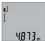
3a BkIOUOBAHe HaIa3ePHNbHcH3a H3-MepBaHe HATNCHETe eHOKpAHO KpAToKtpaH0 6yToHa H3MepBaHe 2.
H3MepeHata cToHocCe H3o6pa3raHa pega 3a pe3yntata b.
Pn HeKoNOKpAHTH NOCLEOBATeHN H3MEpBaHn HaNbJXHHpeyIaTHe Na NocEeHNHe 3MepBaHn Ce Noka3BAt HA peDobete 3a N3MepeHn CTOHCTn a.
N3mepBaHa Hnnoi (BHXTe dHr.C)
3a n3MePbAHe Ha IIOUHaHTCHeTe HeKoJIOKoKaTHo 6yToHa
3,DOKATo HA NCIJIeCe IONBn CnMBoNTa H3MePBAHe Ha PIOUH
CneTOBAH3MepTe NocNEIOBATEHNObJINHnHaTaN HPOUHata, Taka, KaKTo H3MepBaTe DblJINHa. Na3epHNrTbUcOCTaBA BKIOUeH MEKdy DBete H3MepBaHn.
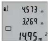
CnepipnKIOUbaHe Ha BTOPOI H3MEpBaHne IIOoTa CE H3NCJIbA aBTOMATuHO nCe H3O6pa3BaHa peDa 3a pe3yntata b. OTdENHITe H3MEpeHn CTOHCT He H3O6pa3BaHa peOBete a.
H3mepBaHe Ha 06em (BHXTe mR.D)
3a n3MepBaHe Ha o6emn HaTHCHETe HEKONKOKpaTHo 6yToHa 3,doKaTo Ha nCIIe Ce NOBn CNMBOJbT 3a n3MepBaHe Ha o6emn
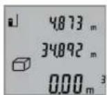
CneTOBAH3MepTe NocleDObaTeHNO
bIbXHHATA,IMPOUHHTA HBCOuHATA,
Taka,KAKTO H3MEpBaTe bNkHa. Na3epHnHr TbHcOCTaBA BKnIOueH MeKdy H3MePBAHnTa.
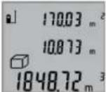
CneipnKIOUbaHe Ha TpeTOTO H3MepBa He o6eBt Ce H3YNcIbA abTomaTHO H ce H3o6pa3raHa peJa 3a pe3yITata b.
OTdENHHTe H3MepeHH CTOnHOCTn Ce H30-6pa3aBAt Ha peoBete a.
CTOHOCTHn HAD 999999 m3 He MoTaT Da 6bDat N3o6pa3EH, HA DmCnpee Ce NoBBA, ERROR".Pa3deneTe N3MePbaHn o6em Ha YaCTH, KOHTo MoKeTe Da N3MePHTe NOOTdEINHO n CneI TOBa Da cb6epete.
HenpeKbchaTo H3MepBaHe (BHXTe 0Hr.E)
PnHnpeKbchaTo H3MePbaHe H3MePbTeHNHTypeMoKe Da6bIe npemecTBaH cIpMa OeBbATA TOka, KaTO H3MepeHaTcTouHOCT ceaktyaHnHpa BcEK0,5s.HanpImep Mo


130|Блгарский
KeTe da ceOTdaneueHTeOTcHeHa KEnaHTo pa3cTOrHHe,TeKyUTo pao3cTOrHHe CE BnKa HENpeKbCbTaTO.
3a pexHM Ha HENpeKbCHato N3MepBaHe HAHTCHeTe 6yToHa 9, DOKATO Ha DCNPIE CE NOBn CHMBONbT 3a HENpeKbCHato N3MepBaHe. 3a CTAPtnpaHe Ha N3MepBaHETO HATCHeTe 6yToHa N3MepBaHe 2.
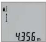
AkyaIHaTn3MpeHcSTOHocCe H0-6pa3BaHa peHa 3a pe3yntTa b.
CHaTnCKaHe Ha 6yToHa 2 PpeKpaTHBaTe HEnPeKbCHaTOI N3MePbAe. IocneJHO N3MepeHATA CToHOCCT OCTaBA H3o6pa3EHa HApeBa. IOBtOPho HAtnCKaHe Ha 6yToHa N3MePbAe 2 CTApTHpa HEnPeKbCHaTOI N3MePbAe OTHaNo.
HenpekbchatoN3MepBaHe ce N3KIOUyBa aBTOMaTHUHO cnE 5 min. NocEnHO N3Mepenata cToHOCCTOcTaba Ha pepa 3a pezynTata b.
HnHpeKTHo H3MepeBaHe Ha BncoUHa / EdnokpTaHO H3- MepeBaHe no TeOpemaHa IHTarOp (BHXTe fhr.F)
HnHnpeKTHoTO H3MePbaHe HA BHCouHc CnyKn 3a OnpedenHa Ha pa3ctOHHN, KOtHO He MoT a Da bBdAT H3MepeHN HenoCpeCTBeHo, HAp. 3aIOTo NO NbTa HA NbUa HMa npEnrTCTBHe HnH 3aIOTo B KpaHnTa TOKa HMa OTpa3BaA uoBbpxHOC.TouHn PezYntaHc NeocTnRa cMo AKO pNcBtEHTO H3MePbaHe Ce CnA3Ba CtpNKTHo PpAB Bbl (TeopeMa HaPiTarOp).
BHHMaBaIte HaanHata ToKaHa H3MepBaHTo (Haip.3aHnHpa6bHa H3MepBaTeHNHyaPe)daOCTaHe HeNPomeHeHa npn BCNUKN eHNuHn H3MepBaHn B paMKHTe Ha 1IOCTHOTo H3MepBaHe.
Mexdy OTdHnTe H3MePbAHn Na3epHnT NbOcTaBa BKnIO-ueH.
HaTNCHe HeKoNkoKpaTHO 6yToHa 3doKaTO Ha dnCnner ce NOBn CHMBoJbT 3a 06KnHO H3MepBaH e No TeOpemaTa HA NITarop
N3MepeteOTceKHTe,1"u,2"BnocouehaTnocneoBatoHnOCT,KAKTOOBKNHOBeHO N3MEpBaTeDJIKNHH.IpnTOBaBHmABaIte bTbTMeKdyOTceKkata,1"UNbpceHaTaOTceKaX"daepab.
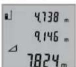
CneipnKIOUBAHe Ha NocEHOTo H3-MepBaHe peyntaTbTa TbpceHaTaOTceKaX"Ce NOBBAHa peJa 3a peyntaH b.CtoHHoCTHe 3a OTJeHNHe H3MePBAHHa Ca H3NcAHn Ha peoBete a.
H3tpnBaHe Ha H3MepeHcTOnHocTH
Upe3 KpaKOTpaHn HATNCKaHe Ha 6yToHa 4 MoKeTe Da H3TpHe TocneIHO H3MepeHaTcOHIocCT BbB BCNU PeKIM HA H3MEpBaHe. Upe3 MHOROKpAHO KpaKTOpaHn HATNCaHe Ha 6yToHa Ce H3TpHbTa B6paTHa NocNeIOBaTeHOCHTMaPeHen Te Ppen TOBA CTOHOCTH.
Cb6npahe Ha 3mepenH cToHocTH
3a da cb6bpuate H3MEpeHcTOnHOCTn, nbpBOu 3BbPwTe He06xOIMTOH3MEpBaHe.CneTOBaHaTHCHeTe 8yToHa "Pioc"8.3a NotBbPxDeHHe HaIncnpeCe H3Opa3Ra CmBONBT."
3a da cb6hpate 06em HnHnOu, cneI npBTO 3abpueho H3MepBaHe hATNCHEte 6yToHa,Pioc8.3a NotBbpxDeHne HaDCNNE BnBOOT CmBOna 3a 6eM/nIOU ce H3o6pa3Ra CBMOblT,4
CneT ToBa H3BbPWeTe BTOPO T3MePBAHe.

3a noIyuaBaHe Ha pe3yIITata O t Cb6npaHeto HATHCHEte Oue BeHNbX 6yToHa, "PiKo8." Cb6npaEMITE ce N3O6pa3aBAt Ha peIOBete 3a H3MEpeHH CTOnHOCTNa, C6OpbT - Ha pEDA 3a pe3yIITaN b.
CneH3uHcHbAHe HaCyMaTa KbM HeR
MOrat da 6bDat Do6aBeHn Dpyr H3MepeH nToHocTH, aKo npedn CboTBeHTO H3MepeBaH 6bDeH HATNCKaH 6yTOHbT ,Pioc8.
Yka3aHnHa 3a cb6bnpaHe:
He b3MOK HO CMEcHTo Cb6HpAe Ha dIbnJHHn, IIOUH nOEBMn. Ako HAp. ONiTate Da Cb6epete DblJHKHa c IIOUI, pHi HAHTCKaHe Ha 6yToHa, INIOc" 8 Ha DCNPIER 3a KpATKO Ce NOBBAHaADINCBt, ERROR" (TpeuKa).CneI TOBa H3MEpBaTeHNHtYpeD CE BpbUa B NocNeIHO N3IOI3-BAHnR peKHM Ha H3MEpBAHe.
- Dó6aBc BnHaHpe3yntaTbT ot ENo n3MepBaHe (Hanp. cToHOCT Ha 06em); npn HnpeKbChato n3MepBaHe ce Do6abra N3nHcAHTa Ha peda 3a pe3yntaTa b cToHOCT. CympaHeto Ha OTdENH n3MepeHH cToHOCT h OT peoBOTe a cToHOCT. CympaHeto Ha OTdENH n3MepeHH cToHOCT h OT peoBOTe.
N3BaXdAHe Ha pe3yIITaTH OT N3MepBaHETO
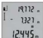
3a nBaxJaHe Ha hMpeHn CTOHOCn HnCHcHete 6yToHa 3a nBaxJaHe 5,3a NOTbpxJHHe Ha nCnIe Ce NOBBa CHMBoJIbT,“. HaHHbTa Ha paOba e aHAnOHTuHn He CbUpaHe Ha hMpeHn CTOHOCn".
Yka3aHn3a pa60Ta
06xynka3aHHN
No Bpeme Ha 3MepBaHe npHemaaata nea 12 n OTBopbT 3a
n3xOJnnaIa3epen bI 11 He Tpr6BaJa 6bDat 3aKpHBn.
No Bpeme Ha 3MepBaHe ypeBt He Tpr6Ba Da 6bJe pmeCCT
BaH (c N3KIOUeHHe Ha peXIMa, HenpeKbCHato 3MepBaHe"). 3aToBA No BB3MOXHOCT dONHPaTe 3MepBaTeHNH
ypeD IO HEnoDBNkHa ONOpHa NOBbpXHOCT.
ФakTOpH, BnHReeUH BpXy DnHaNa3OHa Hn3MePbAHe
Hana30bHa H3MepBaHe 3aBnCOT CBTINHHITE YcNOBn H OtpKaTeHNHTe CBOIcTBa HA NOBbpXHOCTTa,do KOTo Ce H3MepBa.3a No-Do6pa BnIMOCHT Ha Na3epHn IbY npu pao Ta HA OKPHTO Hn PnCHNtA CbHNeBa CBETNHa H3No13BaTte CneuaHInTE OUYHa 19 (He Ca BKIOUeEH B OKOMIIeKTOBA-Ta) H OTPa3raBaTa MEPteHa IIOUka 20 (He E BkIOUeHa B OKOMIIeKTOBAta), INI 3aceHueTe NOBbpXHOCTTa,do KOTo H3MepBaTe.
ФakTopn, BnHReueN BbPxy ToHocTtHa H3MepBaHeto
Bb3 ochoBa Ha non3BaHnTe npH n3MepBaHTo foN3uYeCKn efeKTHe MoT aD bBdA tN3KIOUeHH Bb3HKnBauI rpeuKn
BbIrapckn | 131
npn H3mepBaHeTo Do pa3nnuHn NOBbpxHoCTn. B TOBa YncNo Bn3at:
- p03pa uHHNOBbpXHOCTH(HaNP.CTBKNO,BOa),
OTpa3aBaunIOBbpxHOCTH(HaNP.NOIPAHNMeTaHIN PpeMEn,CTbKNO), - nopeCTH NOBbpxHOCTH (HaNP. H3OJaUNOHHN MaTePnaH),
- NOBbpxHOCTn C rpanaBa ctpkTpya (Hanp. rpyba MaHnka, eCTeCTBeH KaMbK).
Pn Heo6xOJIMOCT Pn H3MepBaHe Do TAKHb NA OOBpXHOCTN H3IOJI3BaIte OTPa3BaIa MepHTeHa IIOUka 20 (He e BKNIOyeHa B OKOMNIJEKTOBkata).
OCBeH TOBA rpeuH NOKa3AHN MoT Da CE NOyUaT npn H3-MepBaH Do NOBbPxHOCTN, KOHTO Ca NoI bTbI.
TouHOCTa Ha H3MepeHaTa CTOnHOCT MOKeJa Ce NOBnRe CbIIO Taka OT HAHNuHTo Ha Bb3dUShn CNOEBe CbC CHENrpaHEnHTa TEMnepaTypa NIN INHINpeKTHN OTPaXeHn.
IpoBepKaHaToHocTtHaH3MepBaHe HaDbJxHH
MoXeTe Da npoBeprToUHocTtHa Hn3MepBaHe Ha DbJxHHnNo CnEHNHaYH:
- Ⅲ6epete OTeCya C NoCToHHa DbJnHm MEmdy 1 N 10 m, KOrTO Bn E N3BecTHa C DoCTaMbHa TOuHOCT (HAp. IInpoHnHata Ha cTaA, BnCOUHnHa Bpata). N3MepBaHata OTeCuKa Tp8Ba Da E B3aTBopeHo NOMEueHne, NOBbPxHOCTHa ToKATA, DO KOrTo H3MepBaTe - rnaJa Ka N OTPa3RaBa a Jb- uHTe do6pe.
-Измерете отсукаТа 10пьтпосnéдОВаTeнHO.
OTKIOHeHHeTo Ha eINHHuHTe H3MePbAHnO t cpeHata CTOnHOCT He Tp8Ba Da hAaBnWabat ± 2 mm. 3aHNWeTe n 3a-na3eTe H3MepeHHTe CTOHOCn, 3a Da MOKeTe Da cpaBHnTe TOOHCTTa Ha H3MePbAEHnry ypeI NO-KbCHO.
Pa6oTa cbc ctaTHB (DOnbHHHTeHn H npCnco6neHne)
H3no13BaHTo HA cTaTHB e Heo6xOJHMO Oc06eHO npH H3mepBaHe Ha rOlenMn DbIckHH. KaTO h3no13BaTe OTBopa C pe36a14 3axBaHete ypeHa KbM IIOUkata 3a 6bp3o 3axBaAha He cTaTHBa 18 Nn OH 6bNHOBeH cTaTHB 3a fOtoanapatn. 3aterHeTe rC BnHTa 3a 3actonOpRBAhe Ha IIOUkata 3a 6bp3o 3axBaAha He cTaTHBa.
IocBaTe CbOTBeTHO OTnpaBHnA paBHHa 3a H3MepBaHe CbC CTaTHB Upe3 HaTnCKaHc Ha 6 (OTnpaBHpaBHHa pe360BNOTBOP).
TpeuKN - npnHnH 3a Bb3HKnBaHe HnHaunHn 3aOTCTpaHnBaHTo HM
PpHnHaOcTpaHbAe
IpeynpeHnHHaTcMbON3aTeMnepaTypa(f)MHra, He eBb3MOXHO H3BbPbBaHTo Ha H3MePBAnH
He nToTnBaIte H3MepBaTeHnHa ypeD BbB BOa Hn DpyrTHeTuHOCTH.
N36bpcBaIte 3aMbpcBAHnIa Tc Meka,NeKo HABNaJxHeHa Kbpna.He N3non3BaIte NoCtBaun npenapTu nn paTBoPurten.
OTHACHTe Ce CNEUAnHO KbM PnHMeMaTAta Neua 12 CbCbIIOTo BHIMAHHe, C KOETe OTHACHTe KbM OUnHa Hn ObekTnB Ha fOtoanapat.
Ako Bbnpekn npeun3HOTOpnpn3BOcTBO HBMATenHO n3NHTBaHe h3MepBATEHNHTypeDce NOBpeDu, pEmoHTb Tp8Ba Da b6Ne h3Bbpweh B OTOpn3HpaH cepBu3 3a eneKtpoHHCTpyMeHTHa BoW. He ce ONtBAteJa OTBapTe N3MepBATEHNHTypeD.
PnHHeo6xOAnMoCT OTepeMOHTIpeOCTaBnTe H3MePBatenHHypeD B qHaTata 17.
CepBn3 nTexHnueckn CbBETH
OTROBOPH HABPPOCTC OTHOCHPOEMHTN NOIDpBXKATA Ha BaaHnIPOyKT MOXETe Da NOLYNTe OT HAaHnCEPBUN3EN OTdE. MoTAtkHN UePTexN INHFOpmAua 3a pe3epBHN vacTNMOXETe Da HAMPeNTe CbIOHa aDPEC:
www.bosch-pt.com
Ekmbt Ha Boi 3a Texnueckn CbBETn npHIOKeHHN Ie OTROBOPn CyBOJONCTBHe Na BbIPOCITE Bn OTHOCHO HAWNTnpOdykTNnDOnbHHTENHnPnncnocobJeHHaT
Mon, np Bbnpocn n np np npbyahe Ha pe3epBn qactn BN Harn noocuBaTe 10-umpehen KaTANOKeH HOpE, n3nncaH ha TaBeKata Ha ypea.
PobepBouE0OД-Блгарн
Boi CepBn3 LcHbtp
TapaHNoHHn H3BbHrapaHNoHHn peMOHTn
6yn.YepnBpbx51-6
FPI Bn3HeC zHbP 1407
1907 Codon
Ten.: (02) 9601061
Ten.: (02) 9601079
ΦaKc: (02) 9625302
www.bosch.bg
Бракувае
N3MepBaTeHNH ypei, DOnbInHTeHNHe TnpCnOc6JIeHN H onaKOBKeTepra6Ba da 6baatnoJoxHeHa eKOIOrHuHa nppepa6Otka 3a ycb0BaHe Ha cbDpKaunte Ce BTRxCypOBHN. He n3XbBpIaIte N3MepBaTeHNH ypei n AkymyNaTOPhn6 BatePN/6ATEPHn pni 6ntoBHTe OTnabu!
Cama 3a cTpaHnOT EC:
CbrrnacHo Ebponeecka dHpeKTHBa 2012/19/EC m3MepBaTeHN ypeDN n cb- rnacho Ebponeecka HpeKTHBa 2006/66/OAkyMynatOpHN nHnO6NHOBeHN bateHN, KOHTo He Morat da CE nONB3AT NOBEHe, Tp8BaDa ce CbHpat OT
IeHIO Hda6bDaT NOHaAHHa NoXoHa npea60Ka 3a ONON30TBOPBaHe Ha CbDpKaaUHTe CB TAX CypOBHH.
Ppaba3aW3mehHn3ana3eHn.
MaKeDoHcKn
Be36eHocnHaNoMeHH

CtyeynatCTBaTpe6aDaCe npouHTaATn da ce BHHMaBAHa HNB,3a Da MoKe 6e36eHNO 6e3 onacnoct da pa6oHTe co OBOJ Mepen ype. DOKONky MePHNOT ypeI He ce KOpNCTH cornaCHO npHNOxKeHNTE HHCTpyKun,MOKe Da CE HApyun
fhyHKnJaTa Ha BrpaDeHHe 3aWHTTH MExAHN3MBO MEPnOT ypeD. He ja OWTeYBAJte O3HaKaTAt 3a npdynpEyBaBe Ha MEPnOT ypeD. IO6POyBAJTE BOBNE YIATCTBA H INPEDADETE T3AEHO CO MEPHNOT ypeD.
BHHMaHHe -DOKONKy KOpNCTHTe DpyrHy ypeHn 3a NODeCyBaHBe n paKyBaHBe OCBHe OBHe HABeDEHnte NIN NONHaKBn NOCTANKN, OBA MOKe Da DOBeDe Do ONaCha H3IOXeHOCT Ha 3paueHe.
MepHnotypeceHCnpaCyBaCoHaTnnc3a npdynpyeBaBe(O3NaueHoHa npHKa3oT Ha MepHnotypeHa rpaHnKata cTpaHa co 6p0j 15).
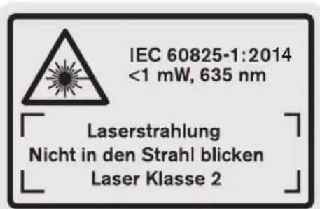
DOKONKy TeKcTHa HAnenHnCata 3a npEynpeyBaHe He e Ha BawHot ja3NK, Bp3 Hero 3aIeTe ja HAnenHHaTa H BawHot ja3NK npE npBata ynoTpe6a.
He ro hacouybaje nacepckno3paKa Ha
Hnca HnN XnB0THn He norneHybaTe
DnpekTHo BO Hero HnH HeroBata
pefneKcnja. TaKa MoKe Da rH 3acIeNITe
HnCaTa, Da npEni3BnKate HecpeKn nn da
rN OUITeNTe OUYte.
Dokonky nacepcknot 3pak Docnee do ouhne, Behdaw Tpe6a da rH 3aTbOpHTe nda ja TprHete rnaBata od nacepcknot 3pak.
He Hk Kopnctete Nacepcknte Ounna KaKo 3aHTTHm ouHna. Nacepcknte OUnna CnyKAT 3a noD6po npeno3HaBaHbe Ha NacepCKNt 3paK, Ho He 3aHTNYBaat OJ NacepckTO 3paueHbe.
He rKopnCTe Nacepcknte Oouna KaO oouna 3a coHue nn NaB Go c0o6paKaJot. Nacepcknte Oouna He daBaat ZenocHa UV-3aunTa H ro HaManyBaat npeno3habahe To ha 6on.
He BpweTe HNKAKBn npeHn Ha nacepcKHO type.


MaKeNoHcKn | 133
MepHnOT ypeI cmEe Ia ce nonpaba cmo Oc ctpaHa KaBnHnKnyBa nCTpyeH nepcoHAn co opnHHanH pe3epBnH denOBn. CaMo HA ToJ hauH N Ke 6nTe CnpyHn BO 6e36eHocTa Ha MEPHnOTypeI.
He n octabajte decaTa da ro Kopnctat nacepcknot Mepen ype63 hazop. Moke da rnaacnenat npynte liuca nopadn HeBHMaHne.
He pa6oTe co MepHnOypeB BO OKoNHa KaDe NoCTOn OnaCHOCT OekCNIO3Ja, KaDE HMa 3aNaNNB TeHOCTH, rac Hn npAHHa. MepHnOypeDco3da BckPn, KOH MoKe da ja 3anaIat npBaTb Hn napeata.
Onnc Ha npOn3BODOT MOKHOCTa
Be monnme OTbopete ja npeknonehata ctpanuca co npka3 Ha MEPHNOYpei, Hdpxete ja OTbOpena Dokea ro qntate ynatCTBoto 3a ynotpe6a.
Ynotpe6a co cooDBeTHa HameHa
MepHnoTypeHaMeHET3aMepeHeHaOdaaneueHoCT, DOnJxHHBcHHpactoJaHjaHaIpcMeTyBaBeHa NoBpUHHnBOyMeHH. MepHnoTypeHaMeHET3a MepeHe BO BHaTpeWeH HaDBopeWeH npocToP.
Texnukn noaToun
| Дигитален ласерскm мерени урею на далоча | GLM 50 |
| Бpoj на дeн/артник | 3601 K72 2.. |
| Мерно поle | 0,05-50 M A) |
| Точность рпс мереньeto (Tинчна) | 1,5 MM±0,05 MM/M B) |
| Точность рпс мереньeto (Tинчни, нето ворну усаны) | 1,5 MM±0,15 MM/M B) |
| Hajмala щени за на писка 1 М M | |
| Temпература рпс пабота | -10°C...+5°C |
| Temпература рпс сладиралье | -20°C...+70° |
| релатова влажноct на воздунхот макс. | 90% |
| Клеса на пасер | 2 |
| Тини пасер | 635 nm, <1 mW |
| Диjsаметар на ласерски зразк (pрии 25°C) okoly | |
| -Во 10 м пасто jaане | 6 MM D) |
| -Во 50 м пасто jaане | 35 MM D) |
| АВТOMATИКA за исклuyва.Table пос Okoly | |
| -Пасер | 20 c |
| -Мерен у徕 (бez меренье) | 5 мINH |
| Бастени | 2x1,5VLR03(AAA) |
| Бастени кени | 2x1,2VHR03(AAA) |
| Рок на trаенье на бастени окуny | |
| -Едионецни мераьа | 10000 E) |
| -Кontинуншкою мераьe | 2,5чE) |
| Дагитален ласерский мерен уред на далоча | GLM 50 |
| Текина сорлесно EPTA- Procedure 01:2014 | 0,14 кг |
| Димензий | 53 x 114 x 30 MM |
| Вид на заштета | IP 54 (разштета од прав и прскаве на вoda) |
A) Dometot Ke 6bné noronem,doKoNky nacepckoto cBETno noObope ce BpaKa od nobPunHata Ha zenta (koHTpoInHO, he peFneKTnpauKn) NdoKoNky nacepckaTouKa e nocBETna BO ONDoc HAcOKoHnTO OCBeTnyBaBe (BHATpeHNPiocToPIcpank). PnHnEOBONH yCOnBn (Ha np.3a MepeHe BO HADBopeeHn pOCTOP co Jako COHBeBO 3pauehe) MOxHo e Da e NotepHo, da ja yNtPepbte CEnHata Tabna.
B)Пи Мере He Od 3aHnOt pa6 Ha MEPnOtypeI.Пи HENOBONH yCNOB KAcO Ha np.CNlHa CoHcEBA CBETINHa NII NOIO pePfKeTnpaKa NOBpUHa ce OeKyBa BnJaHne od ± 0,15mm / m .Пи HENOBONH yCNOB ce OeKyBa BnJaHne od ± 0,05mm / m
C)BoyHKunjataKoHTHHynpaHOpeHe,MaKcHMaJIHaTa pa60tha Tempepatya H3HeCyBa +40^
D) UpiHATA Ha nacepckata HnHna 3aBnCn od coCTABOT Ha NOBpuHATA y cNoBHe Ha OKoHnHa.
E) Co 1,2-BONTHN 6aTePnCK NcHn Ce Bo3MOxH NOMAky MepeBa OTKoJIky Co 1,5-BONTHN 6aTePnH. HabeEnHot pK Ha TpaHe Ha 6aTePnJaCe OJHecyBa Ha MepeBa 6e3 OCBETnyBaBe Ha Ekaphot.
Cepnckno6poj 13 hca cneuФнkaunohata nloquKa cnkykn 3a jaacha ndentnФнkaunja Ha Baunot MpeH ypei.
Nlyctpaunja Ha KOMNOHEHTN
HmepnpaheTo Ha cInKHe Co KOMHOENTn Ce OJHecyBa Ha npka30Ha MePHte anapTa HrpaHcNkata CTpAHua.
1EkpaH
2 Konue MepeHe
3 Konue 3a NOBpHnHcKO MepeHe, MepeHe Ha BOnyMeHn HINHInpeKTHO MepeHe Ha BNCHN (ITaropa)
4 Konue 3a 6pnueHe / konue 3a BknyBaHe/NCkyBaHe
5KoJIeMHyC
6 Konue N36op Ha pepepeHTHO HNBO
7 Dpkaa3a BpBkata
8 Konhe Nync
9 Konue 3a Mepehe HaDIOJKNHH KOHTHHynpaHO Mepehe
10 Tpkloneu Ha nperpadaT3a 6atepnjata
11 N3ne3 Ha nacepcknOr 3paK
12Приемна leka
13 Cepinck boj
14 1/4"HaBoj
15 Hatnnc 3a npdeynpeyBahe Ha nacepot
16ФИКСИРаБЕHAПОКЛОЕТЯнпperpaДАТаЗбATEPиJA
17 3aunTHa TaunHa


134MaKeDoHcKn
18 CtaTHB
19Iacepckn ouhna
20 ZeiHa Tabna 3a Iacepot*
*OnnhaHATA onpema npHKaKaHa Ha cNkHTe He e den oCtahdappHOT o6em Ha Hcnpoka.
PjKETe rnpnHcHato konHcTo 3a noBnkyBaHe Ha nOo6peHHTe cyHKuHH.
ElenmHTnHa npHKa3OT
a PeoBn co n3MepeHaTa BpeHocT
B PeoBn copeaynTat
cMepnduHKu
T
MepenheHaDolJxHnH
↑
MepeHe Ha BpeMeTpaeHBe
MepeheHaNoBpUHH
MepeHeHaBonymEn
A
EINHO BMOpebe co KOpCTeBe Ha IITaropa
D BknyeH nacep
e PepepeHTHO HNO Ha MepeHbeto
fPpeynpeyBaHBe3aTmpepaTypaTa
gIpeynpeyBaBe3a6atepnjata
hIpnka3a rpeuKa ,ERROR
MoHTaxa
CtabaBe/MenyBaBeHa 6aTepn
3a pa6oTa co MePHOTypeCpePnOpaByKaKOpHeBa ankAnHO-MaHraHcKn 6aTePN.
Co 1,2-BOIHTHbATEPNCE BO3MOXHN NOMAIky MepeHa OTKONKY CO 1,5-BOTTHbATEPN.
3a da ro tBopHe kaKaOT od nperpaData 3a 6atePHN 10 npHTNCHEt H Ma MEXAHImOT 3a 3aKJyUbaBe 16 N 3BaTe Ro kanaKOT od nperpaData 3a 6atePHN. CTABe Tn BatePHNte BHaTpe. PnTOA BHMAbajTe Ha NOOBITE BO corNaCHOCT co npHka30T Ha BHaTpeHATA cTpHa oD nperpaData 3a 6atePHN.
PnBMeTHyBaHbTeHa BaTePNHTe, BHIMAbJTe Ha TouHNTe NOOBn CnopeD CNKHTe BO nperpaTada 3a BatePHN.
Dokonky 03hakata 3a 6atepuja ce nojabn npbnat ha ekpaHOT, Bo3MOxHN CE yUte hajmaNky 100 eHnHeHH MepeBa.ФyHKuJaTa KOHTHynpaHO MepeBc e DeakTHBnPaHa.
Dokony 03aKaTa 3a 6atePna Tpenka, Mpa da ce 3aMeH aTePNTE OHN. 6atePcknTe KeHH. He Moke da ce H3BpHmpeHe.
Cekoraa 3amemyBaJTe r n Cte Batepn OeDnA. Kopnctete camo batepn Od eEN pON3BOOHTen CO hCT kanaTET.
Dokonky He cte ro Kophtene Mepnhot ypei noBeke Bpeme,3BaTeTe r6batePHTe OD Hero.Dokonky ce nOdoIro Bpeme cKnaHpaHn,6aTePHTe MoKe da KopoDnpaat N da Ce Hcnpa3HaT.
Ynotpe6a
Ctabahe Bo ynotpe6a
He ro octabajte Bknyuhenot Mepeh ype63 Hau30 np ncknyute ro no ynopte6ata. pynte nnca moke da ce 3acnenat od nacepcknT spak.
3aHTTeToMepHnOypeoBnaraHnHpeKTHO H3noxyBaBeHaCOHcEBN3paH.
He ro n3noxybajte MehpnoT ypeHa ekctpemHn TeMnepaTyPH HnO cunnaBn BO TeMnpaTypata.
Ha np. He ro octabajte doIro Bpeme Bo aBtOMoBHnOT. Pn H oIeMn OCuHauaunn BO TEMpepatypata, OCTabeTe Ro MepHHOT ypeJnPBO Da caKINMaTHn3npa, PpeJa ro CTaBHe BO YOnTpe6a. PnE KcTpeMHN TEmpepatyn Hnn OCuaunn BO TEmpepatypata, PpeuHocTa Ha MEPHHOT ypeJ moKe Da ce HapuHn.
H36erHyBaJTe rnyapn H npBpTyBaHata Ha MepHnoTypeI. TIO CNHH NAdBopeuHN BnJHaJHa Ha MepHNOtypeI, ppeIa Ro yNoTpe6He 3a paOta, cekoruaN3BPwTe KOthPona Ha ToOHCTa (BnH NpOBepKa HA ToOHCT npn MepeHe Ha pactoJaHja", ctpaHa 136).
BknyuBaBe/HcknyuBaBe
3a BkyuBaHe Ha MepHnOT ypeI rH mATE cneHNBe MOXHOCTH:
- PnTHNCHTe Ha KOnUyTeO 3a BkNuyyBaHe-NckNuyBaHe 4: MepHnotypeKe Ce BkNuyu N ce Hao'ra Bo yHKunja Ha MepeHe Ha DoJIKHH. Nacepot HeMa Da ce BkNuy.
- PnTnche Ha konuTo MepeHe 2: MepHnotypeI nacepoTKe ce Bknyat. MepHnotypeI ce Hora BO fynKunja MepeHe Ha donxknHn.
He ro hacouybaje 3paKOT CBETNHa Ha Nnua Hn HKNBTOHN He NorneHyBaTe DnpeKTHO BO Hero,dypn HNOI rONema OndaneueHocT.
3a NcknyBaBe Ha MePHNOT ypeI npTHcHete DOIro Ha KOnIeTo 3a BkNpyBaBe-NCKnyyBaBe4.
Dokonyokny 5MH.He ce pHTncHe HneHNO KOnue Ha MepnOType,ToJce HCKnyyBa aBTOMaTCKn 3apAn 3aHTNA Ha 6atepntte.
Ipoec Ha Mepehe
No BknyuBaHeto, Co npntnckaHe Ha KonpyeTo MepeHe 2 MepHnO rypeKcRaW ce Haofa Bo yHKunja MepHe Ha DOnJKNHN. DpyrInTe MEPn HpyHKUn MoKe Da Hn NoCTaBte CO npTnCKaHe Ha OndocHInTe KOHNHa 3a FyHKUn (BND N, Mepn FyHKUn, cTpHa 135).
Kako pepepeHTHO HNBO 3a MpeHbe,po BknyyBaHbeto,e
n36paH 3aHNOt paH Ma MePHOType. IIO npTnCKaHbHa
KoIpye To PepeepTHO HNBO 6 MoKe Da Tg IpomehITE
pepepeHTHO HNBO (BnD ,BnpaHBe Ha pepepeHTHO HNBO
(BnD cInKa A),ctpHa 135).
IocabeTe rOmeHnOTypeCo n36paHOtopepeHTHO HnBO Ha cakahata CTAPTHa TOKA 3a MepeHe (Ha np. sN).
3a BknyBaBe Ha IacepcknT 3paK, KpaTKo npHTNCHe Ha Konyeto Mepebe 2.


MaKeNoHcKn 135
He ro hacouybajte 3paKOT CBETHnHa Ha IINa Hnn XMBOTHn He NorneHyBaJTe DnpeKTHO BO Hero,dypn HN OJrOEMA OndaneueHoCT.
HacouheTo IacepcknOT 3paK KOH cenHaTaNOBpHnHa.3a AKTHBnPaIbe Ha Mepebeto, OHOBO pNITNCHe KpaTKo Ha konueTo Mepehe2.
Co fyHKunjata KOnTHHynpaHO MepeHbe, MepeHbeto 3anohyBa Bednaw npn BknyuBaHe Ha fyHKunjata.
BoobuetaHo, H3MepeHata BpeHocT Ce nojabyBa BO pok Od 0,5c,a hajdoaHa No 4 c.BpeMeTaepHeTo Ha MepeHeTo 3aBnCnOpaTOnoTo,CBeTIOChNte YcNOBn I pePNeKTHpauKn CBOjcTbHa NaeHATA NOBpuHa.1o 3aBpUyBaHbHa MepeHeto,TacepckHotpak ABtOMaTCKKe ce NCKnyu.
OkoKny no OKony 20c. no Bn3npaHbTo He ce H3BpHmepHe, nacepcknot3paK aBTOMaTCKn Ce NCKJyUyBa 3apAn 3aHTHa Ha 6atePnTE.
BnpaBeHa pepepeENTHO HNBO(BnDn CnkaA)
3a MepebeTo MOKe Da H3epeTe TpN pa3nHn pepeHTn HHOa:
3aHnOpaHaMepHnOypei(Ha np.npnoCTabyBaHe HaSnIOBn).
- npedHnoT pa6 Ha MePHNoType1 (HaNP. npi MepeHe, NoHybajn o edeH pa6 Ha maca),
- cpeHHa Ha HABoJt 14 (HaIp.3a MepeHb co CtaTnB).
3a n36bop Ha pepepeHTHO HNO, npntnckajTe ro konyeto 6,doNeKa He ce npkaKe cakahoto pepepeHTHO HNO haekpaHOT. IIO CEKoe BknyuBaHe Ha MEPHnot ypeI, 3aHnOt paHa MEPHnotypeI e npetxOHO NOCTaBeH Kako pepepeHTHO HNO.
OcbTnyBaHe Ha ekpaHOT
OCBETnyBaHbETO HA ekpahOT ATOMATCKn Ce AKTHBnPA CNOpeD OCBTNEHOCTa Ha OKONHHATA. DOKOKNy PO BKNyUByBaHbeto Ha OCBTNYBaHbeto HA ekpAHOT He CE pNITNCHE HEKOE KONue, ToJ ce 3aTeMHyBa 3apadn 3auTTHa 6aTepeHNTE.
Mepn yHKnn
EhOCTaBHO MepeHe Ha DoJXHHN (BnH CNKka B)
3a MepeHe Ha IOnKHHn npHTCKajre ro KOnHcTe 9,doKeHa ekpahOT He ce nojABn npKa30 3a MepeHe Ha IOnKHHn
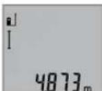
3a BknyBaHBe Ha nacepoTn 3a MepeHe, Kpatko npntCHeTe Ha konHTo MepeHe 2.
M3mepeHATA BpeHOT Ke ce npKkKe BO peoT co peynta b.
PnMpeHBeHaNoBKeDOnKHHEnEOHNO Dpyro,Ke ce npKaKaTpe3yTTaHTeOJNocJeHNHTeMepeBaBOpeoBN KaedeepnKaKaHaH3MepeHATA BpeHOCTa.
MepebeHa noBpHmH (BnH cnka C)
3a MepeHe Ha NOBpHHH pNITNCkajTe rO KOJIeTo 3,doNeKa Ha ekpaHot He ce nojABn pNka30 3a MepeHe Ha NOBpHHH
Ha KpaJ, H3MepeTe JaDOLINHATA H WIPHNATA eHNO NO dpyro KaKo Kaj MepeBeto Ha DOLINHNI. POMefy DBete MepeBa, NacepcknOT 3pak OCTahyBa BkIyuEH.
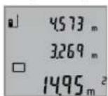
No 3aBpuWbAbe Ha BtOPO MepeHBe,
NOBpUHHaTAt ABTomATcKn Ce IpeCMetyBa
Ike ce npKaKe BO peoT co peyITa b.
IOeINHeuHInTe H3MepeHN BpeHOct
CTojat BO peoBHTe Co H3MepeHN
BpeHOctn a.
MepeheHaBonymEn(BuDnCnHKaD)
3a Mepehe Ha BONYMeH npHTnCKajTe rO KOHTe 3doEkaHa ekpaHot He ce noJaBn pNkA3OT
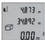
Ha kpaJ, n3Mepete ja donjNHaTata,
HpiHATA H BnCHATA eHNO NO dpyro
kako Kaj MpebeTo Ha doJKNH.N. PomefY
tpTe MepeBa, nacepcknot 3pak
OCTaHyBA BKnyeh.

Ito 3aBpuYBaHe Ha TpeTOTO MepeHe, BOnyMeHOT AToMAtCKn Ce npeCmTeByaKe ce npKae Bo peJOT co pe3yITa b. NoeINHeuHHTe H3MepeHN BpeHOctTH CTOjat BO peJOBITE CO H3MepeHN BpeHOctHa.
BpeHocHTe Hd 999999M3 He MoKJe Da Ce npKaKaJat,Ha ekpaHOT ce noJaByBa,"ERROR".BolymEnHeITo Tpe6aJaHn3MePte, NoTeNeTc Hn Ha NonoEInHeuH MepeHa,3a OndeHNo Da CE npeCmTaAT n peHCTpnpaAT HNBHTe BpeHocTH.
Mepehe Ha Bpemetpaiebe (BnHc nkaE)
Pn KOHTHyHpaHTo MepeIbe, MepHHOTypeM0Ke peaTHBNO da ce DbHXK KOH ceta, npu ITO H3MepeHaT BpeHoc Ke ce axkypnpa Ha cekon 0,5c. Hap. MoKe Da ce OdaJeHTe Ha HeKoe pactoJahne od SIO, a MOMENTHO pactoJahne cekorauke bHe duHTINBO.
3a KOHTHHynpaHm MepeHa npTnCKajTe ro KOnyTeo 9,doNeKa Ha ekpaHot He ce noJabN npKka3ot 3a KOHTHHynpaHO MepeHe. 3a cTAP Ha KOHTHHynpaHTo MepeHe, npTnCHeTe ro KOnyTeo MepeHe 2.
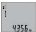
AkyenHATA h3mepeHa BpeHocT Ke ce npkaKe BO peoT co peynta b.
Co nptnnckahe ha konyeto Mepebe 2 ro 3aBpyBaTe KOHTHHypaHTo Mepebe. IocneHa H3Mepeha BpeHnct Ke ce npkaKe Bo peoT co pezytat b.Co
OJHOBO npHTNcKaHe Ha KOUeTo MepeBe 2 KOHTINHypaHOTo MepeBe 3aONuHYBa OJ NOeTOK.
KoTHHnHaHOTo MepeBe aBtOMaTcN Ce NCKnyBaNo 5MH.NocEnHaTa H3MepeHa BpeHocTe Ke ce npKaKe Bo peDcOpe3yntat b.
HINpeKTHoMepeHeHaBnCHN/EdHOCTaHo MepeBe COKPNCTeHe Ha NTaropa(BnDcnKaF)
HINHPeKTHOTMOpeHeHaBcHnCnyKn3aCoONHTyBaHe Ha pactoJahJa, KOH He Tpe6a HnpeKTHO Da ce H3Mepat, 6ndejkn HmApneKu BO TeKOT Ha 3pAKOT Hm Hema CenHa nobPunHa KaKo peFNeKToP Ho paCnOlaRaBe. ToHN pe3yntatN Ke CE NOCTNRHAT Dypn OTKaKo TOUHO Ke Ce 3aDpn

136 | MaKeJIoHcKn
6apAHnOT npaB aor npH oDHOCHTO MepeHe (PiTaropHa Teopema).
BHHMabajte Ha Toa,pepepeHThata Touka Ha MepebeTo (Ha np. 3aHnOt pa6 Ha MePHNOT ypei) Da CTOn TOUHO Ha HCTOTO MecTO pRn CITE POeINHeuH MepeBa 3a Bpeme Ha MePHNOT PPOEC.
PomeynoeHHeHHTe MepeBa,nacepcknOt 3paK octaHyBa Bknyeh.
PnTnCKajTe ro KOnHcTe 3,doNeKa Ha ekpaHOT He ce nojaBn npka303a MepeHe co KopncTeHe Ha PtTaRopa
Kako n kaj dONXHHCKOTMepehe, h3Mepete Tn HHHHnTe ,1" n,2" no OoJ peOocneB. BHHMaBaJte nomEry HHHjata ,1" 6apahata nnHnja ,X" da noctOn npab aron.
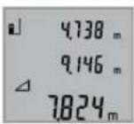
No 3aBpyBaHBe Ha NoCneIeHTo MpeHBe Ke ce PnKaepezYIaTOT 3a 6apaHaTa IHHJa, X" BO peoT 3a pezYIaT b. PoednHeuHIne N3MepEHn BpeHocTH cOJat BO peoBnTE Co N3MepEHn BpeHocTH a.
BpHnebe Ha H3MepeHnTe BpeHocTH
Co KpaTko npnTnCKaHBe Ha konTuTe 4 MoKeJa ra Hn H36pnuTeNoocneHNO COONtHeHNTe NoeHNHeHH N3MepeHH BpeHOCTHBO CHTe MePHN FyHKU. Co NoBekEkpAHO npnTnCKaHbHa konTuTe Ke Ce H36pHwAT NoeHNHeHHte N3MepeHH BpeHocTn NO obPaten peoCneI.
Co6npaIbe Ha H3MepeHHTe BPeDnoCTn
3aIdoBaBaHe Ha N3MepeHn BpHocTH, HajnpBO H3BpuTe npOn3BOJHO MepeHe. Iotoa pInTCHETe Ha KONHTO TlYc 8. Ha ekpaHOT kako NOTbpda ce nojabyBa ,+
3aДоDABaHé Ha BONYMEnH ININ NOBpUHHN, NO npBnOT 3aBpUeH Mepen IpOuec, pNITCHeTe Ha KOnHTo PInyC 8. Ha ekpaHOT kako NtBpIa ce NojabyBa,“Ha JEBaTa cTpaHa oD O3HaKaTa 3a BONYMEn/NoBpUHHa.
Itoa H3BpWeTe N BTOPO MepeHe.
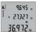
3a npOBepKa Ha 3bIpOT oDVBete MepeBa,yUte eHauN pInTuChete Ha konHTo PnUC 8. IpSecMeTKata Ke ce npKae Bo peOBOITE CO H3MepeHN BpeHOCTH a,a 3bIpOT ce nojAByBA BO peoT3a pezntat b.
Ipo npecmetyBahe Ha 36bnpot,Ha OBOJ pe3yntat Moke da ce Idoaat npTu H3MepeHn BpeHNOCTH,DOKONky nped Mepeheto Ce npHTncHE KOnCuTe Tnyc8.
Cobetn3a co6bnpahe:
BpeHnOHTe3aDJIKNHa,NOBpUHnHaNBOJyMeHHeMOKe MeoOBHTo Da ce cObnpaT.10KOLky Ha np. Ce cObePat BpeHOCT Ha DOnJXHa NOBpUHHa, pN pNTHCKaBe Ha KONyTe OYc8KpAToKceNojAByBa,EROR"HaekpaHot. IToa MeHHOT ypeD MeHyBa Ha NocIeHObAKTNBnPaHaTa MEPHa cyHKunja.
- Ce co6bnpa pe3yntaTOI oEINO MepeBe (Ha np. BpeHnOCT Ha BOYMeH), a pni KOnTHuHypAHO MepeBe npKkaKaHaTa H3MepeHa BpeHnOCT BO peIoT CO pe3yNTaT b. Co6bnpaBeTo Ha POeINHeuH N3MepeHn BpeHnOCTn OJ peIOBITE Co H3MepeHn BpeHnOCTn a He e BO3MOxHO.
Od3emaheHaH3MepeHHBpeHocTH

3aOJ3MaHBeHaN3MepeHInTeBpeHocTn npTHCHETeKoONyToMmHyc5,Ha ekpaHOT3aNOTBpdaCeNojabyBa,-“。 NohTaMOuHATA NoCTaNkaeCnUHa Ha "Co6paBaHeHaN3MepeHInTeBpeHocTn
Cobetn np pa6oTeheTo
OnuTH HAnOMEHH
PnHMaIeKa 12 H3Ne30 HaNacepckNo3paK 11 He CMeT a6HdT NOKPHEH3a BpeMe HA MepeBeto.
MepHnOT ypeI He CMeE da Ce DnKJN 3a BpeMe Ha MepeHeTo (co NcKnlyOo HA cyHKunjata KOHTnHynpaHO MepeHe). IOKoIKy e BO3MOxHo, NOCTaBeTe ro MepHnOT ypeI Ha Ubpcta nOpIora.
BnnaHnaHa MePHoTo none
MepHTo 3aBnOcCBTIOCHNtycNOBn peFNeKTHBnHTe CBOJCTBa Ha CEINHATA NOBpHnHa.3a NoD6pa BNDIOBCT Ha IacePCKNOT 3pAk PnPa 8oHa HADBpeWeH Tepen H IpejAKn COUeBn 3paun Ha IacePCKNTE OuHa19 (onpema) H cENHATA Tabla Ha Nacepot 20 (onpema),nn 3aceHeTe ja cENHATA NOBpHnHa.
BnnaHaHa MePHeoTe3ynta
Iopaun nHnHn efeKTH He moKe Da ce Ncknyu phaKTOT,
Ja npu MepeHeTo Ha pa3nnHn NOBpHnNoafo
norpeuHO mepeBe. Tyka cnafaoT:
-TpaHcnapeHTnIOBpWHn(Hanp.Ctakno,BOa),
- NOBpuHHH To peFNeKTHpaat (HaNP. HcNoHpaH MeTaN, CTAKNO),
-Notop03HnNoBpuHHn(Haip.3oIaUHOHN MaTePnJaHn),
CTpykTpypHpaHIOBpHHN(Ha np.1py6aMaItepna, npnpoDeH KaMeH).
IOKOJIky e BO3MOKHO,Ha OBHe NOBpUHHN KOpNCTe TcENH Ta5na 3a nacepot 20 (onpeMa).
PpeKn npH MepeBeto Ce HcTo Taka MOKHn Kaj HaKoco Bn3npaHn CEHN NOBpHHN.
HcTo Taka Ha MePHaTa BpeHocT MoKe Da BInJaat H npOeNtte 3a BeHTnAaJca Jo pa3nnuHr TemnepaTypr Hn HnDnpeKTHo nPmEnHeTe peFneKCH.
IpeynpeyBaheTo 3a TemnepaTypa (f) TpenKa, MepebeTo He e BO3MOxHO
MepHHOT pe3yntat He yebpnhB
Ten./paKc:02/2467610
Mo6:070595888
OtctpaHyBahe
MepHnTe ypeH, onpemata n am6aJaxHe Tpe6a da ce oTcPahat Ha ekOLOsKn PnpdaTnB HauHH.
He rH pPnajTe MePHnte ypeu H 6aTeepnnte Bo DomaunHata KaHTa 3a f6pe!
Camo 3a 3emjH BO paMKHa EY
CnopeE EBpONckaTpeYNAthBa
2012/19/EU MEpHnTe ypeH nTO CE BOH
ynOTpeBa H DepeKTHnTE HnN
NcKOpHCTeHnTe 6aTePmN CnopeD
peryNaTHBaTA 2006/66/EC Mopa OdJIeHn
da ce coBepat Na de peuKnHpaat 3a
NoBtOHa yNoTpeBa.
Ce 3aDpKyBa npabTo Ha npomema.
Srpski
Uputstva o sigurnosti

Morate da procitate i obratite paznju na sva uputstva kako biste sa altom radili bez opasnosti i bezedno. Ako merni alat ne upotreblavate u skladu sa prilozenim uputstvima, mozte da ugrozite zaistitne mere koje su integrisane u merni alat.
Nemojte da dozvolite da plocice sa upozorenjima budu ne-razumljive. DOBRO SACUVAJTE OVO UPUTSTVO I PREDAJTE GA ZAJEDNO SA ALATOM, AKO GA PROSLEDUJETE DALJE.
- Oprez - akse koriste drugi uredjazi rad ili podesavanje od onih koji su ovde navedeni, ili izvode drugi postupci, moze ovo voditi eksplozijama sa zracenjem.
Merni alat se isporucije sa Jednom upozoravajucom tablicom (uprikazu mernog alata označena na grafickoj stranici sa brojem 15).
IEC 60825-1:2014 <1 mW, 635 nm

ReiJrB+F#J#J#J#J#J#J#J#J#J#J#J#J#J#J#J#J#J#J#J#J#J#J#J#J#J#J#J#J#J#J#J#J#J#J#J#J#J#J#J#J#J#J#J#J#J#J#
雀詠贈公記在龍雀詠聖日蓮歌國龍龍龍龍龍龍龍龍龍龍龍龍龍龍龍龍龍龍龍龍龍龍龍龍龍龍龍龍龍龍龍龍龍龍龍龍龍龍龍龍龍龍龍龍龍龍龍龍龍龍龍龍龍龍龍龍龍龍龍龍龍龍龍龍龍龍龍龍龍龍龍
Mechanics and Electronics Ltd. PT/SAX-ASA
298 Bojeong-dong Giheung-gu Yongin-si, Gyeonggi-do, 446-913
Republic of Korea
080-955-0909
司
函请同,默私来贝托登是朝忘道的
yauuuaaunauuuuauuauuauuauuuuuuuuuuuuuuuuuuuuuuuuuuuuuuuuuuuuuuuuuuuuuuuuuuuuuuuuuuuuuuuuuuuuuuuuuuuuuuuuuuuuuuuuuuuuuuuuuuuuuuuuuuuuuuuuuuuuuuuuuuuuuuuuuuuuuuuuuuuuuuuuuuuuuuuuuuuuuuuuuuuuuuuuuuuuuuuuuuuuuuuuuUU
aannnnn
y
auiuuiuuiuuaauaiiaaauuuunnnnna
Wunwauuuaaunnnae
a

186
aunnnnnaananaananaananaananaananaananaananaananaananaananaananaananaananaananaananaananaananaananaananaananaananaananaananaananaananaananaananaananaananaananaananaananaananaananaananaananaananaananaananaananaananaananaananaananaananaananaananaananaananaananaan ana anannnnaaannnnaaannnnaaannnnaaannnnaaannnnaaannnnaaannnnaaannnnaaannnnaaannnnaaannnnaaannnnaaannnnaaannnnaaannnnaaannnnaaannnnaaannnnaaannnnaaannnnaaannnnaaannnnaaannnnaaannnnaaannnna
aunnnaanannnnnnnnnnnnnnnnnnnnnnnnnnnnnnnnnnnnnnnnnnnnnnnnnnnnnnnnnnnnnnnnnnnnnnnnnnnnnnnnnnnnnnnnnnnnnnnnnnnnnnnnnnnnnnnnnnnnnnnnnnnnnnnnnnnnnnnnnnnnnnnnnnnnnnnnn nn nannnannnannnannnannnannnannnannnannnannnannnannnannnannnannnannnannnannnannnannnannnannnannnannnannnannnannnannnannnannnannnannnannnannnannnannnannnannnannnannnannnannnannnannnannnannnannnannnannnannnann
yuaoyuanyuuyu
alilvnuuunnu uinwnuunwuuuauuauuauuauuauuauuauuauuauuauuauuauuauuuuuuuuuuuuuuuuuuuuuuuuuuuuuuuuuuuuuuuuuuuuuuuuuuuuuuuuuuuuuuuuuuuuuuuuuuuuuuuuuuuuuuuuuuuuuuuuuuuuuuuuuuuuuuuuuuuuuuuuuuuuuuuuuuuuuuuuuuuuuuuuuuuuuuuuuuuuuuuuuuuuuuuuuuuuuuuuuuuuuuuuuuuuuuuuuuuuuuuuuUU
mua
nuiuui
aunauanuunauanuua uauauauauauuuuauuuuuuuuuuuuuuuuuuuuuuuuuuuuuuuuuuuuuuuuuuuuuuuuuuuuuuuuuuuuuuuuuuuuuuuuuuuuuuuuuuuuuuuuuuuuuuuuuuuuuuuuuuuuuuuuuuuuuuuuuuuuuuuuuuuuuuuuuuuuuuuuuuuuuuuuuuuuuuuuuuuuuuuuuuuuuuuuuuuuuuuuuuuuuuuuuuuUU
Jauuuluiinrnnnnaaannnnaaannnnaaannnnaaannnnaaannnnaaannnnaaannnnaaannnnaaannnnaaannnnaaannnnaaannnnaaannnnaaannnnaaannnnaaannnnaaannnnaaannnnaaannnnaaannnnaaannnnaaannnnaaannnnaaannnnaaannnnaaennnnaaannnnaaannnnaaannnnaaannnnaaannnnaaannnnaaannnnaaannnnaaannnnaaannnnaaannnnaaannnnaaannnnaaannnnaaannnnaaannnnaaannnnaaannnnaaannnnaaannnnaaannnnaaannnnaaannnnaaannnnaa annnnnnnnnnnnnnnnnnnnnnnnnnnnnnnnnnnnnnnnnnnnnnnnnnnnnnnnnnnnnnnnnnnnnnnnnnnnnnnnnnnnnnnnnnnnnnnnnnnnnnnnnnnnnnnnnnnnnnnnnnnn
aunnnnnae aannnnnne nnnn nn annnnnnae
nannnnnnnnnnnnnnnnnnnnnnnnnnnnnnnnnnnnnnnnnnnnnnnnnnnnnnnnnnnnnnnnnnnnnnnnnnnnnnnnnnnnnnnnnnnnnnnnnnnnnnnnnnnnnnnnnnnnnnnnnnnnnnnnnnnnnnnnnnnnnnnnnnnnnnnnnnnnn nn n 189)
nnaa
i
- nnnn 4: nnnnnnnnnnnnnnnnnnnnnnnnnnnnnnnnnnnnnnnnnnnnnnnnnnnnnnnnnnnnnnnnnnnnnnnnnnnnnnnnnnnnnnnnnnnnnnnnnnnnnnnnnnnnnnnnnnnnn
- nuiuunun2: 1nuaaiaaaanrnn
aannnnnnae aen nne ane ean ne
Dnannnnnnnnnnnnnnnnnnnnnnnnnnnnnnnnnnnnnnnnnnnnnnnnnnnnnnnnnnnnnnnnnnnnnnnnnnnnnnnnnnnnnnnnnnnnnnnnnnnnnnnnnnnnnnnnnnnnnnnnnnnnnnnnnnnnnnnnnnnnnnnnnnnnnnnnnnnnnnnnnnnnnnnnnnnnn nn nannn nn nannn nn nannn nn nannn nn nannn nn nannn nn nannn nn nannn nn nannn nn nannn nn nannn nn nannn nn nannn nn nannn nn nannn nn nannn nn nannn nn nannn nn nannn nn nannn nn nannn nn nannn nn nannn nn nannn nn nannn nn nennn nn nannn nn nannn nn nannn nn nannn nn nannn nn nannn nn nannn nn nannn nn nannn nn nannn nn nannn nn nannn nn nannn nn nannn nn nannn nn nannn nn nannn nn nannn nn nannn nn nannn nn nannn nn nannn nn nannn nn nannn nn n ann
#
nanaanannnnnaaannnnnnaan 2 nanaananaananaananaananaananaananaananaananaananaananaananaananaananaananaananaananaananaananaananaananaananaananaananaananaananaananaananaananaananaananaananaananaananaananaananaananaananaananaananaananaananaananaananaananaananaananaananaananaananaanana anaa
nannnnnnnnnnnnnnnnnnnnnnnnnnnnnnnnnnnnnnnnnnnnnnnnnnnnnnnnnnnnnnnnnnnnnnnnnnnnnnnnnnnnnnnnnnnnnnnnnnnnnnnnnnnnnnnnnnnnnnnnnnnnnnnnnnnnnnnnnnnnnn
("mnnnnaaunnuA")nn 188
7777777777777777777777777777777777777
nannnnnnnnn 2 nnnnnnnnnnnnnnn
oovvuaiaafoovnuwnnnaon 1000000000000000000000000000000
2
luuunnnnnaaannn ananrnnnnaeauan
1000 0.5 4 4 4 4 4 4 4 4 4 4 4 4 4 4 4 4 4 4 4 4 4 4 4 4 4 4 4 4 4 4 4 4 4 4 4 4 4 4 4 4 4 4 4 4 4 4 4 4 4 4
100


188
nunnnnnuu (nunwunau A)
nunnnnnnnnnnnnnnnnnnnnnnnnnnnnnnnnnnnnnnnnnnnnnnnnnnnnnnnnnnnnnnnnnnnnnnnnnnnnnnnnnnnnnnnnnnnnnnnnnnnnnnnnn
- 1
- 10007777777777777777777777777777777777
- 14 (a. u. uu uununununununun)
1000000000000000000000000000000000000000000000000
nnaannnnnnnn
L
aannnnnnaananaananaananaananaananaananaananaananaananaananaananaananaananaananaananaananaananaananaananaananaananaananaananaananaananaananaananaananaananaananaananaananaananaananaananaananaananaananaananaananaananaananaananaananaananaananaananaananaananaananaanara anaae aee
n
nnaanannnnnnaaun (nannnnnnaB)
nunnnnnnnn nannn 9 nnnnnnnnnnnn nn nnnn "nannnnnnn" I
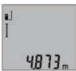
nnaaannnnn 2 aun nnnnnn
aannnnnnaeauanrueaennnnn
nannnnnnnnnnnnnnnnnnnnnnnnnnnnnnnnnnnnnnnnnnnnnnnnnnnnnnnnnnnnnnnnnnnnnnnnnnnnnnnnnnnnnnnnnnnnnnnnnnnnnnnnnnnnnnnnnnnn
nntiau (gnwunau C)
nunnnnnnnnnnnnnnnnnnnnnnnnnnnnnnnnnnnnnnnnnnnnnnnnnnnnnnnnnnnnnnnnnnnnnnnnnnnnnnnnnnnnnnnnnnnnnnnnnnnnnnnnnnnnnnnnnnnnnnnnnnnnnnnnnnnnnnnnnnnnnnnnnnnnnnnnnnnnnnnn nn nannn nn nannn nn nannn nn nannn nn nannn nn nannn nn nannn nn nannn nn nannn nn nannn nn nannn nn nannn nn nannn nn nannn nn nannn nn nannn nn nannn nn nannn nn nannn nn nannn nn nannn nn nannn nn nannn nn nannn nn nannn nn nennn nn nannn nn nannn nn nannn nn nannn nn nannn nn nannn nn nannn nn nannn nn nannn nn nannn nn nannn nn nannn nn nannn nn nannn nn nannn nn nannn nn nannn nn nannn nn nannn nn nannn nn nannn nn nannn nn nannn nn nannn nn n ann
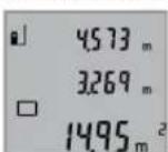
a
nntaun (nnnuuD)
nunnnnnnnnnnnnnnnnnnnnnnnnnnnnnnnnnnnnnnnnnnnnnnnnnnnnnnnnnnnnnnnnnnnnnnnnnnnnnnnnnnnnnnnnnnnnnnnnnnnnnnnnnnnnnnnnnnnnnnn
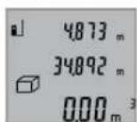
nnaaannnnnnaanennnnaanennnnaanennnnaanennnnaanennnnaanennnnaanennnnaanennnnaanennnnaanennnnaanannnnaanannnnaanannnnaanannnnaanannnnaanannnnaanannnnaanannnnaanannnnaanannnnaanannnnaanannnnaanannnnaanannnnaanannnnaanannnnaanannnnaanannnnaanannnnaanannnnaanannnnaanannnnaanannnnaanannnnaanannnnaanennnnaanann
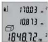
wnnnnnaaannnnnnaanennnnnnnnnnnnnnnnnnnnnnnnnnnnnnnnnnnnnnnnnnnnnnnnnnnnnnnnnnnnnnnnnnnnnnnnnnnnnnnnnnnnnnnnnnnnnnnnnnnnnnnnnnnnnnnnnnnnnnnnnnnnnnnnnnnnnnnnnnnnnn
liangyuanxun yu: "ERROR"
nnaaannnnnnaananaananaananaananaananaananaananaananaananaananaananaananaananaananaananaananaananaananaananaananaananaananaananaananaananaananaananaananaananaananaananaananaananaananaananaananaananaananaananaananaananaananaananaananaananaananaananaananaananaananaanara
J 1000000000000000000000000000000000000000000000000000000000
"1" 2"1"
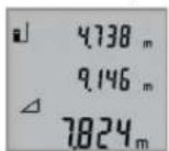
nannnnnnnnnnnnnnnnnnnnnnnnnnnnnnnnnnnnnnnnnnnnnnnnnnnnnnnnnnnnnnnnnnnnnnnnnnnnnnnnnnnnnnnnnnnnnnnnnnnnnnnnnnnnnnnnnnnnnnnnnnnnnnnnnnnnnnnnnnnnnnnnn
17
n4 10000000000000000000000000000000000000000000000000

mnnn189
17
aannnnnnaanennnnnnae nnnnnnnnnnnnnnnnnnnnnnnnnnnnnnnnnnnnnnnnnnnnnnnnnnnnnnnnnnnnnnnnnnnnnnnnnnnnnnnnnnnnnnnnnnnnnnnnnnnnnnnnnnnnnnnnnnnnnnnnnnn
1000000000000000000000000000000000000000000000000000000000
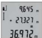
yannnnnnaaannnnnnaan nnnnnnnnnnnnnnnnnnnnnnnnnnnnnnnnnnnnnnnnnnnnnnnnnnnnnnnnnnnnnnnnnnnnnnnnnnnnnnnnnnnnnnnnnnnnnnnnnnnnnnnnnnnnnnnnnnnnnnnnnnnnnnnn nn
nannnnnnaaennnnn nnnnnnnnnnnn nnnnnnnnnnnnnn nn nnnnnnnnnnnn 8 nannnnn
#
- 1777777777777777777777777777777777777777777777777777777777
- aunnnnnaaannnnnnnnnnnnnnnnnnnnnnnnnnnnnnnnnnnnnnnnnnnnnnnnnnnnnnnnnnnnnnnnnnnnnnnnnnnnnnnnnnnnnnnnnnnnnnnnnnnnnnnnnnnnnnnnnnnnnnnnnnnnnnnnnnnnnnnnnnnnnnnnnnnnnnnnnnnnnnnnnnnnnnnn
T
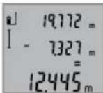
100 100 100 100 100 100 100 100 100 100 100 100 100 100 100 100 100 100 100 100 100 100 100 100 100 100
Jauuunnnnnaa
#
11
nnae nanae nnne nae nane nane (nnnae)
JHAN
ywnnnn nn nnnnnnnnnnnnnnnnnnnnnnnnnnnnnnnnnnnnnnnnnnnnnnnnnnnnnnnnnnnnnnnnnnnnnnnnnnnnnnnnnnnnnnnnnnnnnnnnnnnnnnnnnnnnnnnnnnnnnnnnnnnnnnnnnnnnnnnnnnnnnnnnnnnnnnnn nn nannn nn nannn nn nannn nn nannn nn nannn nn nannn nn nannn nn nannn nn nannn nn nannn nn nannn nn nannn nn nannn nn nannn nn nannn nn nannn nn nannn nn nannn nn nannn nn nannn nn nannn nn nannn nn nannn nn nannn nn nannn nn nennn nn nannn nn nannn nn nannn nn nannn nn nannn nn nannn nn nannn nn nannn nn nannn nn nannn nn nannn nn nannn nn nannn nn nannn nn nannn nn nannn nn nannn nn nannn nn nannn nn nannn nn nannn nn nannn nn nannn nn
JuaHuaHua:WuaHuaWnT
1
- wuWwJouu(a.8.1u u
- 1
-wwwqwu(u.1u - 1
nnuu uauuunnnnaaannr 20 (aunnnnnn)
yannnnnnaaennnnnnnnnnnnnnnnnnnnnnnnnnnnnnnnnnnnnnnnnnnnnnnnnnnnnnnnnnnnnnnnnnnnnnnnnnnnnnnnnnnnnnnnnnnnnnnnnnnnnnnnnnnnnnnnnnnnnnnnnnnn
nannnnnnnnnnnnnnnnnnnnnnnnnnnnnnnnnnnnnnnnnnnnnnnnnnnnnnnnnnnnnnnnnnnnnnnnnnnnnnnnnnnnnnnnnnnnnnnnnnnnnnnnnnnnnnnnnnnnnn
n77777777777777777777
1
- 1000000000000000000000000000000000000000000000000000
- 10
| nanaananaananaananaananaananaananaananaananaananaananaananaananaananaananaananaananaananaananaananaananaananaananaananaananaananaananaananaananaananaananaananaananaananaananaananaananaananaananaananaananaananaananaananaananaananaananaananaananaananaanana ananaananaananaananaananaananaananaananaananaananaananaananaananaananaananaananaananaananaananaananaananaananaananaananaananaananaananaananaananaananaananaananaananaananaananaananaananaananaananaananaananaananaananaananaananaananaananaananaananaananaa 999999 m/m2/m3 | |
| nanaananaananaananaananaananaananaananaananaananaananaananaananaananaananaananaananaananaananaananaananaananaananaananaananaananaananaananaananaananaananaananaananaananaananaananaananaananaananaananaananaananaananaananaananaananaananaananaanana anana ananaananaananaananaananaananaananaananaananaananaananaananaananaananaananaananaananaananaananaananaananaananaananaananaananaananaananaananaananaananaananaananaananaananaananaananaananaananaananaananaananaananaananaananaananaananaananaananaanana anana nana nana nana nana nana nana nana nana nana nana nana nana nana nana nana nana nana nana nana nana nana nana nana nana nana nana nana nana nana nana nana nana nana nana nana nana nana nana nana nana nana nana nana nana nana nana nana nana nana nana |
nnuuwanvuauiuauuuuauuvwunrnnnuuauu u
| ### |
| ### |
| ### |
| ### |
| ### |
| ### |
| ### |
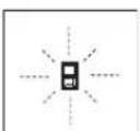
nnnnnnnnnnnnnnnnnnnnnnnnnnnnnnnnnnnnnnnnnnnnnnnnnnnnnnnnnnnnnnnnnnnnnnnnnnnnnnnnnnnnnnnnnnnnnnnnnnnnnnnnnnnnnnnnnnnnnnnnnnnnnnnnnnnnnnnnnnnnnnnnnnnnnnnnn
y
nunnuuuaaunnu
nVvynnnnaaee
nnnnnnnnnnnnnnnnnnnnnnnnnnnnnnnnnnnnnnnnnnnnnnnnnnnnnnnnnnnnnnnnnnnnnnnnnnnnnnnnnnnnnnnnnnnnnnnnnnnnnnnnnnnnnnnnnnn
y
wnnnn nnnn 2012/19/EU
wnnnn nn nnnn 2006/66/EC
wnnnn nn nnnn 2006/66/EC
wnnnn nn nnnn 2006/66/EC
wnnnn nn nnnn 2006/66/EC
julal auiill dabioil
jJJI-06000aL
+213(0)982400992:Jgl
+213(0)34201569:JU
sav@siestal-dz.com:JgjSJIJIJJ
uig
Ug
99-25gjUgS UwGooJI.0p
jg jy jy.2014
+21671428770:
+21671354175:J
sotel2@planet.tn:gjSJL
J
LdoJjSj20
a0-ooJl 1g2
+20222476091-95/+20222478072-73:
+20222478075:JU
boschegypt@unimaregypt.com:giJjSJI
auiu 0o
aayjcbgglgglg yalll o jy
aaiil aie aaiia iaii aaiii 1e aaiy anao
Uulllg UuIbI/psIyIg wUaI sOe
jui
:ba9gjgJslJgJ
2012/19/EU 2012/19/EU
aJoo uol wull 1gaoui
gjgxl aagil wag.laswll
/psIJg2006/66/EC
1jai Lc aSgauwJg aduU U
aull aonio aajbI qio yalil oij
guljub

#
J 1 J 1 J 1 J 1 J 1 J 1 J 1 J 1 J 1 J 1 J 1 J 1 J 1 J 1 J 1 J 1 J 1 J 1 J 1 J 1 J 1 J 1 J 1 J 1 J 1 J 1 J 1 J 1 J 1 J 1 J 1 J 1 J 1 J 1 J
Lio) wai aiaa aiaaa aabll aie yol Jy I 10 lai jkaii mnn (wai aia aiaa aiaa aai JI .alglil wai aiaacn oos
wlll llaoc jy jssuill sjjll gaw y a jol
w gaaa a 3 jll lsc baaal J S .bawllgjglaa
Jgbl Jgbl g2"g1"jafLwJl Jai j 10g j gag jg JgJgJgJgJgJgJgJgJgJgJgJgJgJgJgJgJgJgJgJgJgJgJgJgJgJgJgJgJgJgJgJgJgJgJgJgJgJgJgJgJgJgJgJgJgJgJgJgJgJgJg
aill wai aal aac aas yjw g"X"ugbll aglwl jc, oall wai qol lo b aill auii
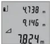
wUJI rA
J 1
(ajgawawawg aajlslslo wlll:
aJU.
gagall aasll aai. llll yuulal g
0.15ggljulg 8a
0,05gaiJuiuaiuaiUauiuaiUaL
Jaiuall jaiall aabg yagaiil gaii iiaaii ojda c
+40℃
.ajgjblg glawl aay juuu baa oae buy D
oJl jSs lac bgs 1.2 pJy Jy Jy Jy Jy Jy E
suiuogdaiUjUull aaloo 1.5 UjU
aulull 1uulll lacI
13 1jlll jll jg gagg jll s c j
jIbai
oJgaaI |j
JUJI 0gJU JjGJU
aabaaill gogll daaol lc oogall
aWw1
Uujjj 2
J 1 J 1 J 1 J 1 J 1 J 1 J 1 J 1 J 1 J 1 J 1 J 1 J 1 J 1 J 1 J 1 J 1 J 1 J 1 J 1 J 1 J 1 J 1 J 1 J 1 J 1 J 1 J 1 J 1 J 1 J 1 J 1 J 1 J 1 J
gagall ajjlll cill 1. wll lsc 1, oal ylaol oq jiaol .dwl wll ocl qbc! ala g wll oos qo! lc yolg .jul
JocuIwI GBBj oJ gI liu IooJ3 oJ 111 JbAsGclaw!OoJgU UJ 50y Saa
gwwjlae wuai jgajl.(15gjluabaa
1e bfo g
(ai)aui
IEC 60825-1:2014 < 1 mW, 635 nm
J 1 J 1 J 1 J 1 J 1 J 1 J 1 J 1 J 1 J 1 J 1 J 1 J 1 J 1 J 1 J 1 J 1 J 1 J 1 J 1 J 1 J 1 J 1 J 1 J 1 J 1 J 1 J 1 J 1 J 1 J 1 J 1 J 1 J 1 J
Jg 0saw s ggo Jg G S Jg 0s
4001wJ1J
g w d afo (59) (sj 0jil jj1 ggi j) gw .CwI o.15 oJaw
IEC 60825-1:2014
< 1mW, 635 nm
Laserstrahlung

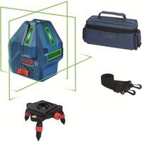


- GLM 50 Professional
- Product Description and Specifications
- Intended Use
- Technical Data
- Product Features
- Display Elements
- Assembly
- Inserting/Replacing the Batteries
- 14|English
- Operation
- Initial Operation
- Switching On and Off
- Measuring Procedure
- Selecting the Reference Level (see figure A)
- Display Illumination
- Measuring Functions
- Simple Length Measurement (see figure B)
- Area Measurement (see figure C)
- Volume Measurement (see figure D)
- Continuous Measurement (Tracking) (see figure E)
- Indirect height measurement / Simple Pythagoras Measurement (see figure F)
- Deleting Measured Values
- Adding Measured Values
- Subtracting Measured Values
- Working Advice
- General Information
- 16|English
- Influence Effects on the Measuring Range
- Influence Effects on the Measuring Result
- Accuracy Check of the Distance Measurement
- Working with the Tripod (Accessory)
- Troubleshooting - Causes and Corrective Measures
- Cause Corrective Measure
- Temperature warning indicator (f) flashing; measurement not possible
- "ERROR" indication in the display
- Measuring result not plausible
- The indication remains unchanged or the measuring tool reacts unexpectedly after pressing a button
- Maintenance and Service
- Maintenance and Cleaning
- After-sales Service and Application Service
- www.bosch-pt.com
- Great Britain
- Ireland
- Australia, New Zealand and Pacific Islands
- Republic of South Africa
- Customer service
- Gauteng - BSC Service Centre
- KZN - BSC Service Centre
- Western Cape - BSC Service Centre
- Bosch Headquarters
- Disposal
- | Français
- Only for EC countries:
- François
- Mesure continue (voir figure E)
- Vaelg referencingeniveau (se Fig. A)
- Bortskaffelse
- Avfallshantering
- XpnooupwaueTovnpoopopo
- Euvtnpnon kal Service
- Suvtnpnoan kkaqapiaooc
- Service kal npoxn ououauxphng
- EAAaδg
- Anoupon
- Movi yia xwpec tnc EE:
- Türkce
- Güvenlik Talimatu
- Zprcovani odpadu
- Cpok cnky6bln3dennna
- IpeuehB KpHTnueckHX OTka3OB H OuH6Ouyhle DeCTBna nepcohana Hnn NOnb3OBaTeTn
- Kpntepnn npedenbhbix coctoHHN
- TnH n nepnoaohocb texnueckoro o6cnyXHBaHH
- Xpahenne
- TpaHcnOpTHpoBka
- Yka3aHn no 6e3onachoctn
- 3JeMeHtbl HnDkaCnn
- C6opka
- YctahOBka/3aMeHa 6atapeek
- Pa6ota c HnHcTpymeHTOM
- 3Kcnnyataa
- BkIIOueHHe/BbIKIOueHHe
- H3mepenme
- Pycckn|105
- H3mepeHne nnoaAn (cm.pnc.C)
- H3mepeHne 06bema (cm.pnc.D)
- IpoJIoKHTeBHoE H3MepeHne (cm.phc.E)
- 106|Pycckn
- KocBeHHoe H3MepeHHe BbICOTb/ PpOcToe H3MepeHne no TeOpeme NpaFopa (cm. pnc.F)
- YdaneHHe H3MepeHHbIX 3NaueHn
- Cnoxehne H3mepenhhix 3haeHHN
- BbIHTaHHe N3MepeHbIx 3NaeHn
- Yka3aHaHnIO npIpuMeHenHIO
- 06üne yka3aHHn
- ФakTopbI, BnHIOUe Ha dHaNA3OH H3MepeHHA
- ФakTopbl, BnHIOUHe Ha pe3ynbTaT n3MepeHHN
- Pycckn107
- IpoBepka ToUHcTHn3MepeHHpaacCTOHHN
- Pa60a co wtaTHbOM (npHnHaIeXHoCTh)
- HencnpabHoctb -PpHnHbI ycTapeHne
- PnunHaYcTaPaHHe
- CepBn KOncynbTHpObaHHe Ha npEmdTnc- noIb3OBaHH npOdyKun
- DnpernoHa:Pocn,Benapycb,Ka3axCTan,YkpanHa
- Pocchra
- Benapycb
- MoHTaX
- BCTABHeHHa/3amHa6atapeHok
- YkpaHcbka 111
- Eknnnyatauaia
- Noataokpo60tn
- BmKahHa/BmHKaHH
- IpoeDypa BmipIOBHaHn
- Bn6ip 6a30Boi nnouHH (nHb. Man. A)
- PiiicbiuyBaHHaHnne
- BmipoiBaIbHI cyHKcii
- Ipocte BmipioBaHHIOBxHHN (INB.MaN.B)
- 112|YkpaHcbka
- BmipbAHHHnOoi (Hb.Man.C)
- BmipiobaHHo6'cMy (nB. man.D)
- Tpmbane BmmpioBaHHa (MnB.MaN.E)
- Henpme BmipobanHn BncOTn / IpocTe BmipobanHa 3a TeopemOPiaropa (Mv. Man.F)
- CTnpaHHBmipraHHx3HaueHb
- DdaBaHnB BMIpAHHx 3HaueHb
- YkpaHcbka 113
- BdHimAHn BmipAnx 3haeHb
- Bka3iBKn 0oO p6oToN
- 3arabhi Bka3iBkn
- ФakTOp HnHbHa diana3OH BmipOBAHH
- AkaTOpn BnNHy Ha pe3ynbTaT BnMipIOBaHHa
- Ipebipka Touhocti BmipioBaHn BiDctahi
- Po6ota 3i w7atnBOM (npHnaIaIaIaIaIaIaIaIaIaIaIaIaIaIaIaIaIaIaIaIaIaIaIaIaIaIaIaIaIaIaIaIaIaIaIaIaIaIaIaIaIaIaIaIaIaIaIaIaIaIaI
- Henonada - npuunnn i ycyneHH
- PpHmHa 1o po6nTn
- Mrae iHukatop BxOy3a Mexi TemnepaTyphoro dianasaOny (f),BmipioBaHHHe MoXJIbBe
- IHdkaTop «ERROR» Ha dncnnei
- Pe3ynbtaBnMipIOBaHnHe npabdoI6HH
- 306paXeHHHaIcnneI3nnMaεTbcH3minHHm a6o BmipHOBaBnH npnaepaeryHaHaTHCKyBaHH KHOK HecNoDIBAHM YHOM
- Cepbic Ta HadaHHa KOHCyIbTauii 0do BnKOpNCaHHa npOdyKuii
- YkpaHa
- Ytniiauaia
- Пишдя краин EC:
- Ka3aKua1 115
- Ka3akwa
- Ohimni nai danany Mep3iM
- Kb3MeTKeHemee naDanaHyubihk KaTeiIKTePi MeH icTe HbIry ce6entepinH,ti3imi
- Uekti ky6benrinepi
- Kb3MeT KepcTeTy Typi MeH XhIniri
- CaKray
- TacbImaay
- Kayinci3ik HycKaynapbi
- Onwey aici
- 118|Ka3a3kla
- Heri3ri Ka3bIKTbIKTbI TaHday (A cypetin KapaHbI3)
- HcnnneJkapbifbl
- Onwey yhknnaapbl
- Kai y3bHdbkTb1 onuey (BCypetIH kapaib3)
- Aydaanbienwey (Cypetin Kapaanb)
- Keenni enwey (D cypetin kapaanb3)
- Y3dikci3 eHwey (E cypTeH kapaHb13)
- KaHama 6nKtki enwey / Bipnik Hpaarop enwem (Fcypetin kapaib3)
- Bnwey hataxeneepin xoo
- Gnwey Kneemepin Kocy
- Kaazakua|119
- OnweyKeemepin any
- Падалану hyckaynapbi
- KannblHyckaynbIKTap
- Onwey aHaMaFBbHa ecepne
- Conectare/deconnectare
- Eliminare
- TocBaHc/CMHaHa 6aTePnHTe
- Pa6ota c ypeda
- Tyskahe Bekcnnoataa
- BkIIOUbaHe H3KIIIOUbaHe
- BbIrapckn|129
- H3MepBaHe
- H36op Ha otnpabha paBHHa (BnXTe Hr. A)
- OcbetneHnHa dnCnner
- PexmmHaH3MepBaHe
- 06nKHOBeHo N3MepBaHe HaIbIaHHH (BHXTeΦHr.B)
- N3mepBaHa Hnnoi (BHXTe dHr.C)
- H3mepBaHe Ha 06em (BHXTe mR.D)
- HenpeKbchaTo H3MepBaHe (BHXTe 0Hr.E)
- 130|Блгарский
- HnHpeKTHo H3MepeBaHe Ha BncoUHa / EdnokpTaHO H3- MepeBaHe no TeOpemaHa IHTarOp (BHXTe fhr.F)
- H3tpnBaHe Ha H3MepeHcTOnHocTH
- Cb6npahe Ha 3mepenH cToHocTH
- N3BaXdAHe Ha pe3yIITaTH OT N3MepBaHETO
- Yka3aHn3a pa60Ta
- 06xynka3aHHN
- ФakTOpH, BnHReeUH BpXy DnHaNa3OHa Hn3MePbAHe
- ФakTopn, BnHReueN BbPxy ToHocTtHa H3MepBaHeto
- IpoBepKaHaToHocTtHaH3MepBaHe HaDbJxHH
- Pa6oTa cbc ctaTHB (DOnbHHHTeHn H npCnco6neHne)
- TpeuKN - npnHnH 3a Bb3HKnBaHe HnHaunHn 3aOTCTpaHnBaHTo HM
- CepBn3 nTexHnueckn CbBETH
- PobepBouE0OД-Блгарн
- Бракувае
- Cama 3a cTpaHnOT EC:
- MaKeDoHcKn
- Be36eHocnHaNoMeHH
- Onnc Ha npOn3BODOT MOKHOCTa
- Ynotpe6a co cooDBeTHa HameHa
- Nlyctpaunja Ha KOMNOHEHTN
- 134MaKeDoHcKn
- ElenmHTnHa npHKa3OT
- MoHTaxa
- CtabaBe/MenyBaBeHa 6aTepn
- Ynotpe6a
- Ctabahe Bo ynotpe6a
- BknyuBaBe/HcknyuBaBe
- Ipoec Ha Mepehe
- MaKeNoHcKn 135
- He ro hacouybajte 3paKOT CBETHnHa Ha IINa Hnn XMBOTHn He NorneHyBaJTe DnpeKTHO BO Hero,dypn HN OJrOEMA OndaneueHoCT.
- BnpaBeHa pepepeENTHO HNBO(BnDn CnkaA)
- OcbTnyBaHe Ha ekpaHOT
- Mepn yHKnn
- EhOCTaBHO MepeHe Ha DoJXHHN (BnH CNKka B)
- MepebeHa noBpHmH (BnH cnka C)
- MepeheHaBonymEn(BuDnCnHKaD)
- Mepehe Ha Bpemetpaiebe (BnHc nkaE)
- HINpeKTHoMepeHeHaBnCHN/EdHOCTaHo MepeBe COKPNCTeHe Ha NTaropa(BnDcnKaF)
- | MaKeJIoHcKn
- BpHnebe Ha H3MepeHnTe BpeHocTH
- Co6npaIbe Ha H3MepeHHTe BPeDnoCTn
- Cobetn3a co6bnpahe:
- Od3emaheHaH3MepeHHBpeHocTH
- Cobetn np pa6oTeheTo
- OnuTH HAnOMEHH
- BnnaHnaHa MePHoTo none
- BnnaHaHa MePHeoTe3ynta
- OtctpaHyBahe
- Camo 3a 3emjH BO paMKHa EY
- Srpski
- Uputstva o sigurnosti
- 司
- 186
- yuaoyuanyuuyu
- mua
- nuiuui
- nnaa
- #
- 188
- nunnnnnuu (nunwunau A)
- nnaannnnnnnn
- L
- n
- nntaun (nnnuuD)
- 17
- mnnn189
- T
- Jauuunnnnnaa
- JHAN
- JuaHuaHua:WuaHuaWnT
- n77777777777777777777
- nunnuuuaaunnu
- nVvynnnnaaee
- wUJI rA
- oJgaaI |j
Brand : BOSCH
Model : GLM 50 Professional
Category : Laser pointer