
GLL 215 Professional - Laser pointer BOSCH - Free user manual and instructions
Find the device manual for free GLL 215 Professional BOSCH in PDF.
| Product type | Laser pointer |
| Brand / Model | Bosch GLL 215 Professional |
| Dimensions (without swivel mount) | 112 x 55 x 106 mm |
| Dimensions (with swivel mount) | 132 x 81 x 163 mm |
| Weight (according to EPTA 01:2014) | 0.49 kg |
| Power supply | 3 x 1.5 V LR6 (AA) batteries |
| Laser line range | 15 m |
| Plumb point range | 10 m (up and down) |
| Leveling accuracy (lines) | ± 0.3 mm/m |
| Leveling accuracy (points) | ± 0.7 mm/m |
| Self-leveling range | ± 4° |
| Leveling time | < 4 s |
| Operating temperature | -10 °C to +50 °C |
| Storage temperature | -20 °C to +70 °C |
| Protection class | IP54 (dust and splash water protection) |
| Laser class | 2 |
| Wavelength (laser line) | 630-650 nm (red) / 500-540 nm (green) |
| Main functions | Horizontal and vertical lines, plumb points, automatic leveling, locked pendulum unit, automatic shut-off after 120 min |
| Included accessories | Swivel mount RM 1, universal holder BM 1, laser target, laser viewing glasses, case, calibration, tripod BT 150, telescopic rod BT 350, protective cover |
| Maintenance and cleaning | Clean with a soft, damp cloth; do not use detergents or solvents; regularly clean the area around the laser beam exit |
| Safety | Do not direct the beam at eyes or animals; do not look directly into the beam; use the laser viewing glasses only to improve visibility, not as protection |
| Spare parts and repairability | Repair by an authorized Bosch after-sales service; use only original spare parts; order via www.bosch-pt.com or SAV DIRECT |
Frequently Asked Questions - GLL 215 Professional BOSCH
User questions about GLL 215 Professional BOSCH
0 question about this device. Answer the ones you know or ask your own.
Ask a new question about this device
Download the instructions for your Laser pointer in PDF format for free! Find your manual GLL 215 Professional - BOSCH and take your electronic device back in hand. On this page are published all the documents necessary for the use of your device. GLL 215 Professional by BOSCH.
USER MANUAL GLL 215 Professional BOSCH
no Original electric properties
A. Alogarized object
Original isalpnl Lalima
pl lost uscia gezinalpa
Ppynodni npovd k pounbni
Laser Radiation. Do not
stare into beam . Class 2Consumer Laser Product
EN50689:2021
IEC60825-1:2014, ≤ 1mW 630-650 nm
GCL 2-15 G

Laser Radiation. Do not
stare into beam.Class 2
Consumer Laser Product
2021
mW.500 540cm<1mW.630-650m
4
5

6
Deutsch
Sicherheitshinweise

www.bosch-pt.com/serviceaddresses
Entsorgung
All instructions must be read and observed in order for the measuring tool to function safely. The safeguards integrated into the measuring tool may be compromised if the
measuring tool is not used in accordance with these instructions. Never make warning signs on the measuring tool unrecognisable. SAVE THESE INSTRUCTIONS FOR FUTURE REFERENCE AND INCLUDE THEM WITH THE MEASURING TOOL WHEN TRANSFERRING IT TO A THIRD PARTY.
Warning! If operating or adjustment devices other than those specified here are used or other procedures are carried out, this can lead to dangerous exposure to radiation.
The measuring tool is delivered with a laser warning sign (marked in the illustration of the measuring tool on the graphics page).
If the text of the laser warning label is not in your national language, stick the provided warning label in your national language over it before operating for the first time.
Do not direct the laser beam at persons or animals and do not stare into the direct or reflected laser beam yourself. You could blind somebody, cause accidents or damage your eyes.
If laser radiation hits your eye, you must close your eyes and immediately turn your head away from the beam.
Do not make any modifications to the laser equipment.
Do not use the laser goggles (accessory) as protective goggles. The laser goggles make the laser beam easier to see; they do not protect you against laser radiation.
Do not use the laser goggles (accessory) as sunglasses or while driving. The laser goggles do not provide full UV protection and impair your ability to see colours.
Have the measuring tool serviced only by a qualified specialist using only original replacement parts. This will ensure that the safety of the measuring tool is maintained.
Do not let children use the laser measuring tool unsupervised. They could unintentionally blind themselves or other persons.
Do not use the measuring tool in explosive atmospheres which contain flammable liquids, gases or dust. Sparks may be produced inside the measuring tool, which can ignite dust or fumes.

Keep the measuring tool and the magnetic accessories away from implants and other medical devices, e.g. pacemakers or insulin pumps. The magnets inside the measuring tool and accessories generate a field that can impair the function of implants and medical devices.
- Keep the measuring tool and the magnetic accessories away from magnetic data storage media and magnetically sensitive devices. The effect of the magnets inside the measuring tool and accessories can lead to irreversible data loss.
Product Description and Specifications
Please observe the illustrations at the beginning of this operating manual.
Intended Use
The measuring tool is intended for determining and checking horizontal and vertical lines and plumb points.
The measuring tool is suitable for indoor and outdoor use. This product is a consumer laser product in accordance with EN 50689.
Product Features
The numbering of the product features shown refers to the illustration of the measuring tool on the graphic page.
(1) Laser beam outlet aperture
(2) Battery warning
(3) Pendulum lock indicator
(4) Laser point operating mode button
(5) Laser line operating mode button
(6) Battery compartment cover
(7) Locking mechanism of the battery compartment cover
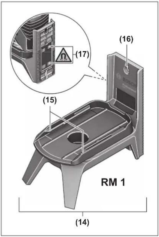
(8) Guide groove
(9) On/off switch
(10) 1 / 4 tripod mount
(11) 5 / 8 "tripod mount
(12) Serial number
(13) Laser warning label
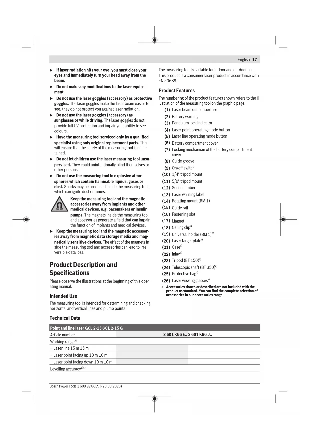
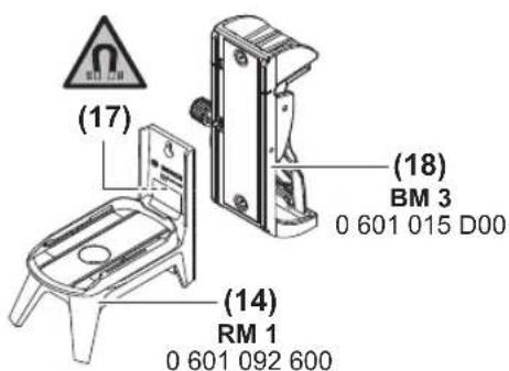
(14) Rotating mount (RM 1)
(15) Guide rail
(16) Fastening slot
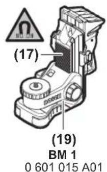
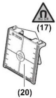
(17) Magnet
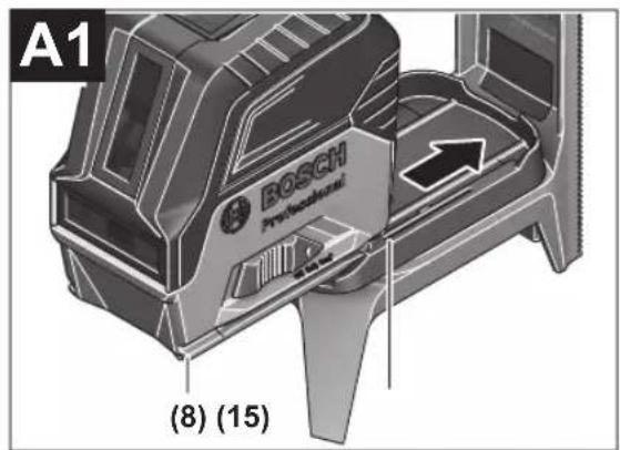
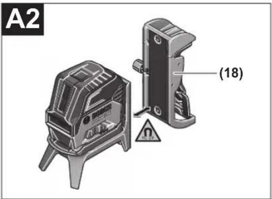
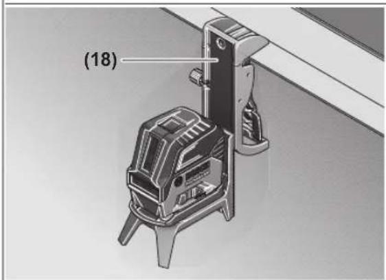
(18)Ceiling clip
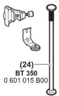
(19) Universal holder (BM 1) ^a)
(20) Laser target plate
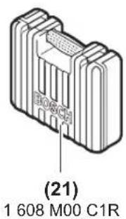
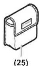
(21) Case
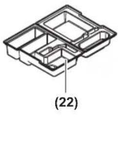
(22) Inlay
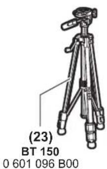
(23) Tripod (BT 150) ^a)
(24) Telescopic shaft (BT 350) ^a)
(25) Protective baga)
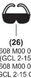
(26) Laser viewing glassesa)
a) Accessories shown or described are not included with the product as standard. You can find the complete selection of accessories in our accessories range.
Technical Data
| Point and line laser GCL 2-15 GCL 2-15 G | |
| Article number | 3601 K66 E.. 3601 K66 J.. |
| Working rangeA) | |
| - Laser line 15 m 15 m | |
| - Laser point facing up 10 m 10 m | |
| - Laser point facing down 10 m 10 m | |
| Levelling accuracyB)C) | |
18|English
| Point and line laser GCL 2-15 GCL 2-15 G | ||
| -Laser lines ±0.3 mm/m ±0.3 mm/m | ||
| -Laser points ±0.7 mm/m ±0.7 mm/m | ||
| Typical self-levelling range ±4° ±4° | ||
| Typical levelling time < 4 s < 4 s | ||
| Operating temperature -10°C to +50°C -10°C to +50°C | ||
| Storage temperature -20°C to +70°C -20°C to +70°C | ||
| Max. altitude 2000 m 2000 m | ||
| Relative air humidity max. 90% 90% | ||
| Pollution degree according to IEC 61010-1 | 2D) | 2D) |
| Laser class 2 | 2 | |
| Laser line | ||
| -Laser type | < 1 mW, 630-650 nm | < 10 mW, 500-540 nm |
| -Colour of the laser beam | Red | Green |
| -C6 | 1 | 10 |
| -Divergence | 0.5 mrad (full angle) | 50 × 10 mrad (full angle) |
| Laser point | ||
| -Laser type | < 1 mW, 630-650 nm | < 1 mW, 630-650 nm |
| -Colour of the laser beam | Red | Red |
| -C6 | 1 | 1 |
| -Divergence | 0.8 mrad (full angle) | 0.8 mrad (full angle) |
| Tripod mount | 1/4", 5/8" | 1/4", 5/8" |
| Batteries | 3 × 1.5 V LR6 (AA) | 3 × 1.5 V LR6 (AA) |
| Operating duration in operating modeB) | ||
| -Cross-line and point mode | 6 h | 6 h |
| -Cross-line mode | 8 h | 8 h |
| -Line and point mode | 12 h | 10 h |
| -Line mode | 16 h | 12 h |
| -Point mode | 22 h | 22 h |
| Weight according to EPTA-Procedure 01:2014 | 0.49 kg | 0.49 kg |
| Dimensions (length × width × height) | ||
| -Without rotating mount | 112 × 55 × 106 mm | 112 × 55 × 106 mm |
| -With rotating mount | 132 × 81 × 163 mm | 132 × 81 × 163 mm |
| Protection rating | IP54 (dust and splash-proof) | IP54 (dust and splash-proof) |
A) The working range may be reduced by unfavourable environmental conditions (e.g. direct sunlight).
B) At 20-25°C
C) The values stated presuppose normal to favourable environmental conditions (e.g. no vibration, no fog, no smoke, no direct sunlight). Extreme fluctuations in temperature can cause deviations in accuracy.
D) Only non-conductive deposits occur, whereby occasional temporary conductivity caused by condensation is expected.
The serial number (12) on the type plate is used to clearly identify your measuring tool.
Assembly
Inserting/Changing the batteries
It is recommended that you use alkaline manganese batteries to operate the measuring tool.
To open the battery compartment cover (6), press the locking mechanism (7) and lift open the battery compartment cover. Insert the batteries.
When inserting the batteries, ensure that the polarity is correct according to the illustration on the inside of the battery compartment.
If the batteries become weak, the battery warning indicator (2) will flash green. The laser lines will also flash for approximately five seconds every ten minutes. The measuring tool can still be operated for approximately one hour after the first flash. If the batteries drain completely, the laser lines will flash one more time just before automatic shut-off.
Always replace all the batteries at the same time. Only use batteries from the same manufacturer and which have the same capacity.
Take the batteries out of the measuring tool when you are not using it for a prolonged period of time. The batteries can corrode and self-discharge during prolonged storage in the measuring tool.
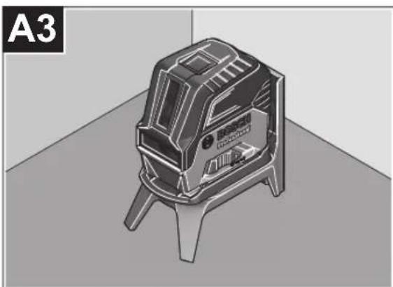
Working with the RM 1 rotating mount (see figures A1-A3)
You can use the rotating mount (14) to rotate the measuring tool 360^ around a central, always visible plumb point. This enables you to set up the laser lines without having to change the position of the measuring tool.
Place the measuring tool with the guide groove (8) on the guide rail (15) of the rotating mount (14) and slide the measuring tool all the way onto the platform.
To disconnect the measuring tool, pull it off the rotating mount in the opposite direction.
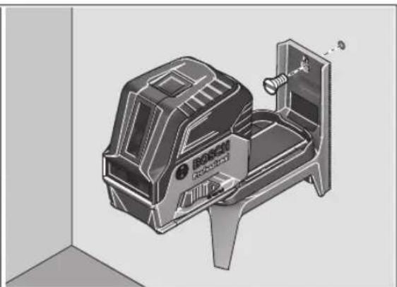
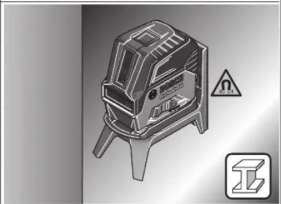
Rotating mount positioning options:
- Standing on a flat surface,
Screwed to a vertical surface, - On metallic ceiling strips using the ceiling clip (18),
-
On metallic surfaces using the magnets (17).
-
Keep your fingers away from the rear side of the magnetic accessory while attaching the accessory to surfaces. The strong pulling force of the magnets may jam your fingers.
Operation
Starting Operation
Protect the measuring tool from moisture and direct sunlight.
Do not expose the measuring tool to any extreme temperatures or fluctuations in temperature. For example, do not leave it in a car for extended periods of time. If it has been subjected to significant fluctuations in temperature, first allow the measuring tool to adjust to the ambient temperature and then always carry out an accuracy check before continuing work (see "Accuracy Check of the Measuring Tool", page 21).
The precision of the measuring tool may be compromised if exposed to extreme temperatures or fluctuations in temperature.
- Avoid substantial knocks to the measuring tool and avoid dropping it. Always carry out an accuracy check before continuing work if the measuring tool has been
subjected to severe external influences (see "Accuracy Check of the Measuring Tool", page 21).
- Switch the measuring tool off when transporting it. The pendulum unit is locked when the tool is switched off, as it can otherwise be damaged by big movements.
Switching On/Off
To switch on the measuring tool, slide the on/off switch (9) to the on position (for working with the pendulum lock) or to the on position (for working with automatic levelling). As soon as it is switched on, the measuring tool emits laser beams from the outlet apertures (1).
Do not direct the laser beam at persons or animals and do not stare into the laser beam yourself (even from a distance).
To switch off the measuring tool, slide the on/off switch (9) to the Off position. The pendulum unit is locked when the tool is switched off.
Never leave the measuring tool unattended when switched on, and ensure the measuring tool is switched off after use. Others may be blinded by the laser beam.
If the maximum permitted operating temperature of 50^ is exceeded, the tool shuts down to protect the laser diode. Once it has cooled down, the measuring tool is operational again and can be switched back on.
Automatic Shut-Off
If no button on the measuring tool is pressed for approx. 120 min, the measuring tool will automatically switch itself off to preserve battery life.
To switch the measuring tool back on after it has been automatically switched off, you can either slide the on/off switch (9) to the "Off" position first and then switch the measuring tool back on, or press either the laser point mode button (4) or the laser line mode button (5).
Temporarily Deactivating Automatic Shut-Off
To deactivate the automatic shut-off function, hold down the laser line mode button (5) for at least 3 s (with the measuring tool switched on). If the automatic shut-off function is deactivated, the laser beams will flash briefly as confirmation.
Note: If the operating temperature exceeds 45^ , automatic shut-off can no longer be deactivated.
To activate the automatic shut-off function, switch the measuring tool off and on again.
Setting the Operating Mode
The measuring tool has several operating modes, which you can switch between at any time:
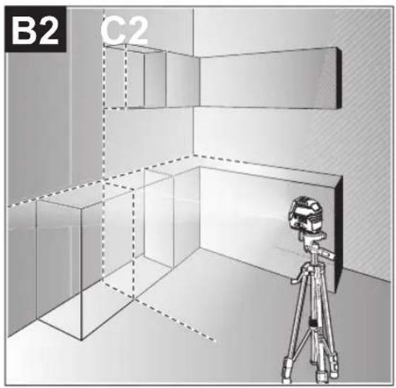
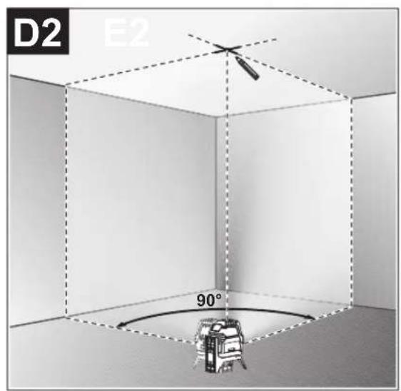
Cross-line and point mode: The measuring tool generates a horizontal and a vertical laser line as well as two vertical laser points, one facing up, the other down. The laser lines cross at a 90^ angle.
Horizontal line mode: The measuring tool generates a horizontal laser line in front of it.
20|English
- Vertical line mode: The measuring tool generates a vertical laser line in front of it.
Positioning the measuring tool in the room displays the vertical laser line on the ceiling beyond the top laser point.
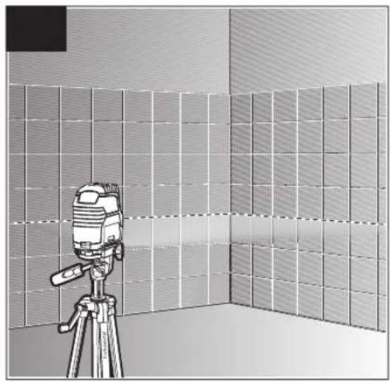
If the measuring tool is positioned directly against a wall,
the vertical laser line almost encircles the entire space (360° line).
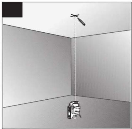
- Point mode: The measuring tool generates two vertical laser points, one facing up, the other down.
All operating modes, apart from point operation, can be selected with both automatic levelling or the pendulum lock.
Working with Automatic Levelling
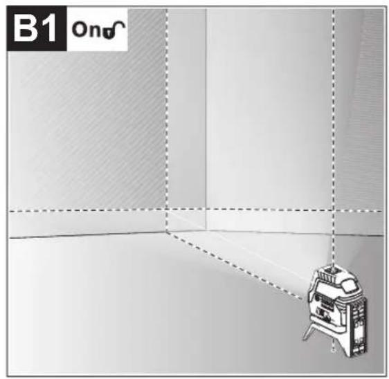
| Sequence of actions Horizontal line | mode | Vertical line mode | Point mode Pendulum lock indicator (3) | Figure | |
| On/off switch (9) in position "n" | ●●● | B1 | |||
| Cross-line mode | |||||
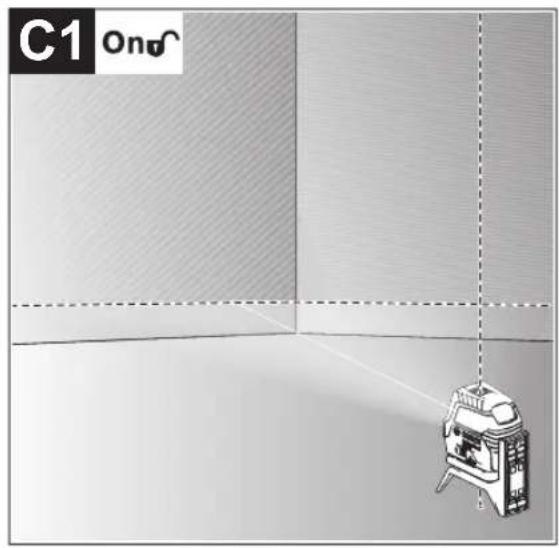
| + | Press the laser line operating mode button (5) once | ●-● | C1 | ||
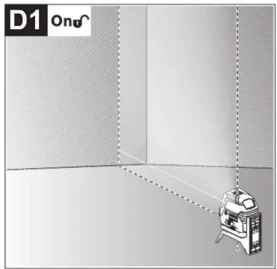
| Press the laser line operating mode button (5) twice | -●● | D1 | |||
| Press the laser line operating mode button (5) three times | --● | E1 | |||
| Press the laser line operating mode button (5) four times | ●●● | B1 | |||
| Cross-line mode | |||||
Point mode can be activated or deactivated regardless of the line mode setting:
| Press the laser point operating mode button (4) once | ●/− ●/− |
| Press the laser point operating mode button (4) twice | ●/− ●/− ● |
If the measuring tool is outside of the self-levelling range, the laser lines and/or points will flash quickly.
If, during work with automatic levelling, you switch to "working with pendulum lock" mode (on/off switch (9) in position
On), the first combination option of this mode's indicators is always activated.
Working with the pendulum lock
| Sequence of actions Horizontal line | mode | Vertical line mode | Point mode Pendulum lock indicator (3) | Figure | |
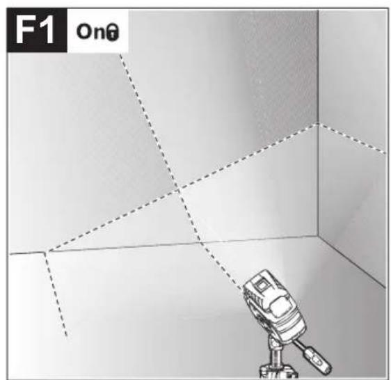
| On/off switch (9) in position "on" | ●●- | Red | F1 | ||
| Cross-line mode | |||||
| + | Press the laser line operating mode button (5) once | ●-● | Red | F1 | |
| Press the laser line operating mode button (5) twice | -●- | Red | F1 | ||
| Press the laser line operating mode button (5) three times | ●●- | Red | F1 | ||
| Cross-line mode | |||||
The laser lines continuously flash slowly in "working with the pendulum lock" mode.
If, during work with pendulum lock, you switch to "working with automatic levelling" mode (on/off switch (9) in position
On), the first combination option of this mode's indicators is always activated.
Automatic Levelling
Working with Automatic Levelling (see figures B1-E1)
Position the measuring tool on a level, firm surface or attach it to the rotating mount (14).
For work with automatic levelling, slide the on/off switch (9) to the "on" position.
The automatic levelling function automatically levels irregularities within the self-levelling range of ± 4^ . The measuring tool has been levelled as soon as the laser beams stop flashing.
If automatic levelling is not possible, e.g. because the surface on which the measuring tool stands deviates by more than 4^ from the horizontal plane, the laser beams will flash quickly.
If this is the case, set up the measuring tool in a level position and wait for the self-levelling to take place. As soon as the measuring tool is within the self-levelling range of ± 4^ , the laser beams will light up continuously.
In case of ground vibrations or position changes during operation, the measuring tool is automatically levelled again.
Upon levelling, check the position of the laser beams with regard to the reference points to avoid errors arising from a change in the measuring tool's position.
Working with a pendulum lock (see figure F1)
For work with the pendulum lock, slide the on/off switch (9) to the "On" position. The pendulum lock indicator (3) lights up red and the laser lines continuously flash slowly.
For work with the pendulum lock, automatic levelling is switched off. You can hold the measuring tool freely in your hand or place it on a sloping surface. This means that the laser beams are no longer levelled and no longer necessarily run perpendicular to one another.
Accuracy Check of the Measuring Tool
Influences on Accuracy
The largest influence is exerted by the ambient temperature. In particular, temperature differences that occur from the ground upwards can refract the laser beam.
In order to minimise thermal influences resulting from heat rising from the floor, it is recommended that you use the measuring tool on a tripod. In addition, position the measuring tool in the centre of the work surface, wherever this is possible.
In addition to external influences, device-specific influences (e.g. falls or heavy impacts) can also lead to deviations. For this reason, check the levelling accuracy each time before beginning work.
First check the height accuracy and levelling accuracy of the horizontal laser line, then the levelling accuracy of the vertical laser line.
Should the measuring tool exceed the maximum deviation during one of the tests, please have it repaired by a Bosch after-sales service.
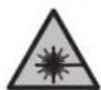
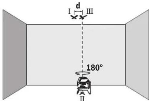
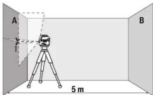
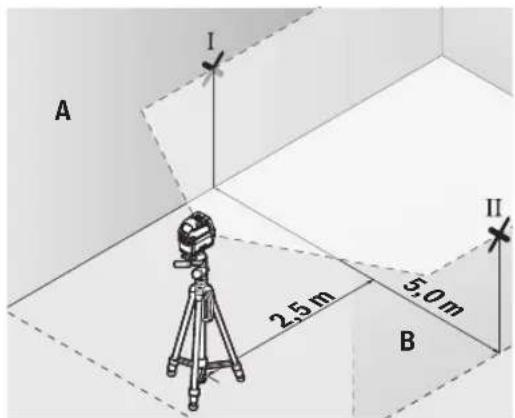
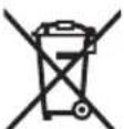
Checking the Height Accuracy of the Horizontal Line
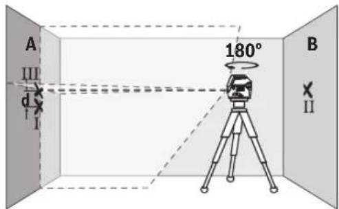
For this check, you will need a free measuring distance of 5 m on firm ground between two walls (designated A and B).
- Mount the measuring tool close to wall A on a tripod, or place it on a firm, level surface. Switch on the measuring tool. Select cross-line mode with automatic levelling.
- Aim the laser at the closer wall A and allow the measuring tool to level in. Mark the middle of the point at which the laser lines cross on the wall (point I).
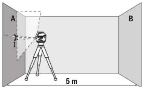
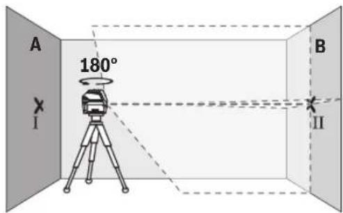
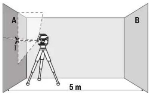
- Turn the measuring tool 180^ , allow it to level in and mark the point where the laser lines cross on the opposite wall B (point II).
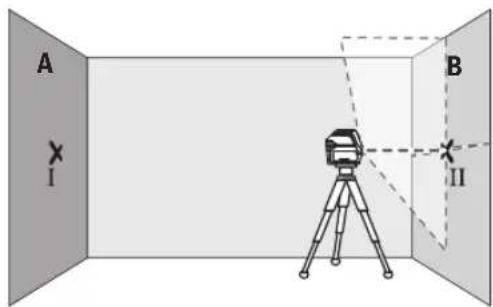
- Position the measuring tool - without rotating it - close to wall B, switch it on and allow it to level in.

Align the height of the measuring tool (using the tripod or by placing objects underneath as required) so that the point where the laser lines cross exactly hits the previously marked point II on wall B.
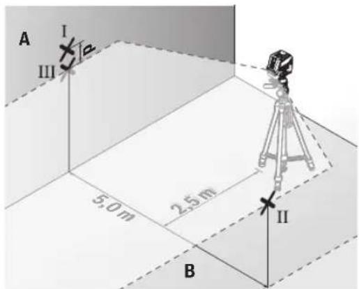
22 | English
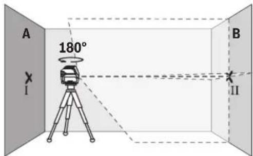
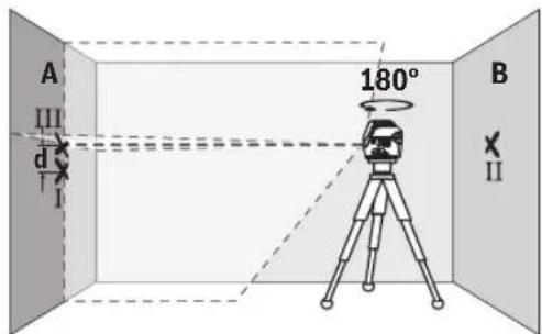
Turn the measuring tool 180^ without adjusting the height. Aim it at wall A such that the vertical laser line runs through the already marked point I. Allow the measuring tool to level in and mark the point where the laser lines cross on wall A (point III).
- The discrepancy d between the two marked points I and III on wall A reveals the actual height deviation of the measuring tool.
The maximum permitted deviation on the measuring distance of 2 × 5m = 10m is as follows: 10m × ± 0.3mm/m = ± 3mm . The discrepancy d between points I and III must therefore amount to no more than 3mm .
Checking the Level Accuracy of the Horizontal Line
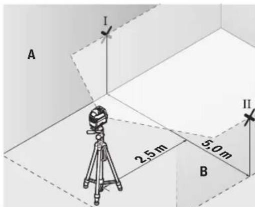
For this check, you will need a free area of 5 × 5m .
Mount the measuring tool in the middle between walls A and B on a tripod, or place it on a firm, level surface. Select horizontal line mode with automatic levelling and allow the measuring tool to level in.
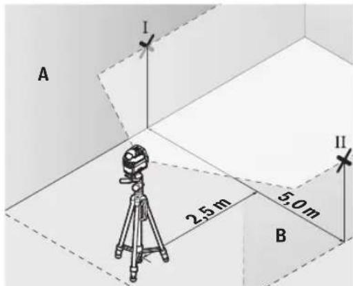
- At a distance of 2.5m from the measuring tool, mark the centre of the laser line on both walls (point I on wall A and point II on wall B).

- Set up the measuring tool at a 5 m distance and rotated by 180^ and allow it to level in.
Align the height of the measuring tool (using the tripod or by placing objects underneath as required) so that the
centre of the laser line exactly hits the previously marked point II on wall B.
- Mark the centre of the laser line on wall A as point III (vertically above or below point I).
- The discrepancy d between the two marked points I and III on wall A reveals the actual horizontal deviation of the measuring tool.
The maximum permitted deviation on the measuring distance of 2 × 5m = 10m is as follows:
10 m × ±0.3 mm/m = ±3 mm. The discrepancy d between points I and III must therefore amount to no more than 3 mm.
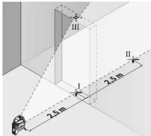
Checking the Level Accuracy of the Vertical Line
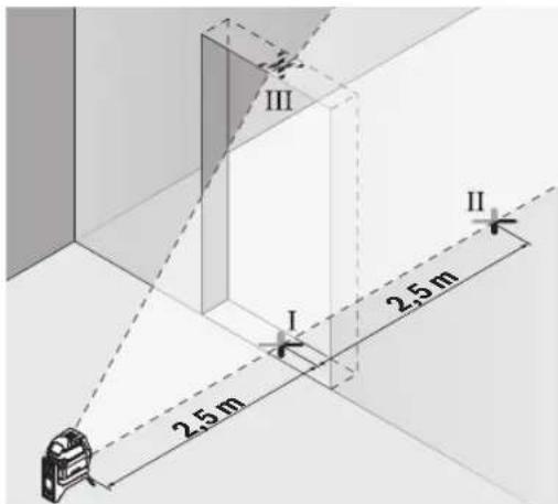
For this check, you will need a door opening (on solid ground) which has at least 2.5m of space either side of the door.
- Place the measuring tool 2.5m away from the door opening on a firm, flat surface (not on a tripod). Select vertical line mode with automatic levelling. Aim the laser line at the door opening and allow the measuring tool to level in.
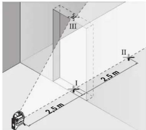
- Mark the centre of the vertical laser line on the floor of the door opening (point I), 5 m away on the other side of the door opening (point II) and on the upper edge of the door opening (point III).
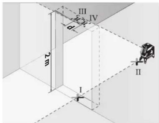
- Rotate the measuring tool 180^ and position it on the other side of the door opening, directly behind point II. Allow the measuring tool to level in and align the vertical laser line in such a way that its centre passes through points I and II exactly.
- Mark the centre of the laser line on the upper edge of the door opening as point IV.
- The discrepancy d between the two marked points III and IV reveals the actual vertical deviation of the measuring tool.
- Measure the height of the door opening.
You can calculate the maximum permitted deviation as follows:
Doubled height of the door opening × 0.3mm / m Example: At a door opening height of 2m ,the maximum deviation amounts to
2 × 2m × ± 0.3mm/m = ± 1.2mm . The points III and IV must therefore be no further than 1.2mm from each other.
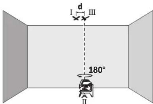
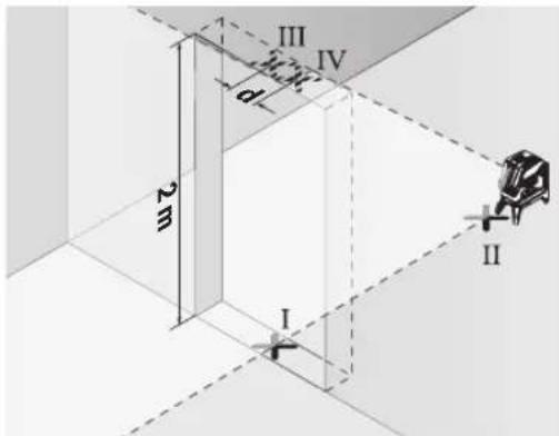
Checking Plumb Accuracy
For this check, you will need a clear measuring space on firm ground with a distance of approx. 5 m between the floor and the ceiling.
- Mount the measuring tool onto the rotating mount (14) and place it on the floor. Select point mode and allow the measuring tool to level in.
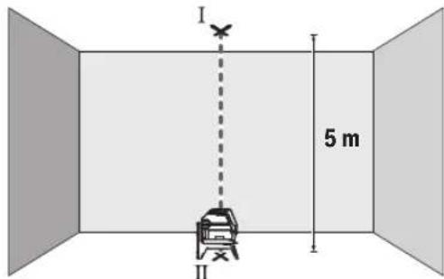
- Mark the centre of the top laser point on the ceiling (point I). Also mark the centre of the bottom laser point on the floor (point II).
Turn the measuring tool by 180^ . Position it so that the centre of the bottom laser point falls onto the marked point II. Allow the measuring tool to level in. Mark the centre of the top laser point (point III).
- The discrepancy d between the two marked points I and III on the ceiling reveals the actual deviation of the measuring tool from the vertical plane.
You can calculate the maximum permitted deviation as follows:
Doubled distance between floor and ceiling × 0.7mm / m Example: At a floor-to-ceiling distance of 5m the maximum deviation amounts to
2× 5m× ± 0.7mm / m = ± 7mm .The points I and III must therefore be no further than 7mm from each other.
Working Advice
Only the centre of the laser point or laser line must be used for marking. The size of the laser point/the width of the laser line changes depending on the distance.
Working with the Tripod (Accessory)
A tripod offers a stable, height-adjustable support surface for measuring. Place the measuring tool with the 1/4'' tripod mount (10) on the thread of the tripod (23) or a conventional camera tripod. Use the 5/8'' tripod mount (11) to secure the measuring tool on a conventional building tripod. Tighten the measuring tool using the locking screw of the tripod.
Roughly align the tripod before switching on the measuring tool.
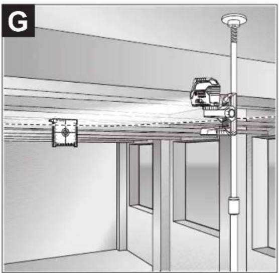
Securing with the universal holder (accessory) (see figure G)
You can secure the measuring tool, for example, on vertical surfaces or magnetisable materials using the universal holder (19). The universal holder is also suitable for use as a floor stand and facilitates the height adjustment of the measuring tool.
- Keep your fingers away from the rear side of the magnetic accessory while attaching the accessory to surfaces. The strong pulling force of the magnets may jam your fingers.
Roughly align the universal holder (19) before switching on the measuring tool.
Working with the Laser Target Plate (see figure G)
The laser target plate (20) improves visibility of the laser beam in unfavourable conditions and at greater distances.
The reflective surface of the laser target plate (20) improves visibility of the laser line. The transparent surface enables the laser line to be seen from behind the laser target plate.
Laser Goggles (Accessory)
The laser goggles filter out ambient light. This makes the light of the laser appear brighter to the eye.
Do not use the laser goggles (accessory) as protective goggles. The laser goggles make the laser beam easier to see; they do not protect you against laser radiation.
Do not use the laser goggles (accessory) as sunglasses or while driving. The laser goggles do not provide full UV protection and impair your ability to see colours.
24 | Français
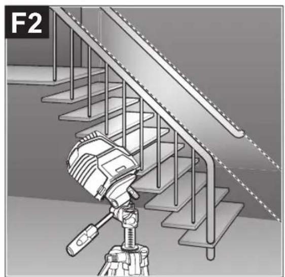
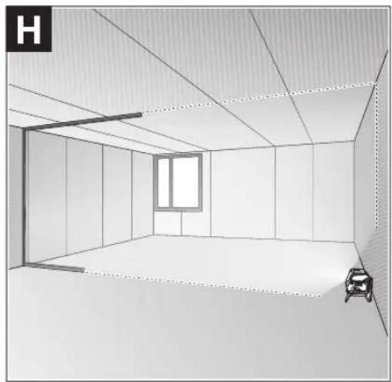
Example Applications (see figures B2-F2, G and H)
Examples of possible applications for the measuring tool can be found on the graphics pages.
Maintenance and Service
Maintenance and Cleaning
Keep the measuring tool clean at all times.
Never immerse the measuring tool in water or other liquids.
Wipe off any dirt using a damp, soft cloth. Do not use any detergents or solvents.
The areas around the outlet aperture of the laser in particular should be cleaned on a regular basis. Make sure to check for lint when doing this.
After-Sales Service and Application Service
Our after-sales service responds to your questions concerning maintenance and repair of your product as well as spare parts. You can find explosion drawings and information on
pare parts at: www.bosch-pt.com
The Bosch product use advice team will be happy to help you with any questions about our products and their accessories.
In all correspondence and spare parts orders, please always include the 10-digit article number given on the nameplate of the product.
Malaysia
Robert Bosch Sdn. Bhd.(220975-V) PT/SMY
No.8A,Jalan 13/6
46200 Petaling Jaya
Selangor
Tel.: (03) 79663194
Toll-Free: 1800 880188
Fax: (03) 79583838
E-Mail: kiathoe.chong@my.bosch.com
www.bosch-pt.com.my
Great Britain
Robert Bosch Ltd. (B.S.C.)
P.O.Box 98
Broadwater Park
North Orbital Road
Denham Uxbridge
UB95HJ
At www.bosch-pt.co.uk you can order spare parts or arrange the collection of a product in need of servicing or repair.
Tel. Service: (0344) 7360109
E-Mail: boschservicecentre@bosch.com
You can find further service addresses at:
www.bosch-pt.com/serviceaddresses
Disposal
Measuring tools, accessories and packaging should be recycled in an environmentally friendly manner.
Do not dispose of measuring tools or batteries with household waste.
Only for EU countries:
According to the Directive 2012/19/EU on waste electrical and electronic equipment and its transposition into national law, measuring tools that are no longer usable, and, according to the Directive 2006/66/EC, defective or drained batteries must be collected separately and disposed of in an environmentally correct manner.
If disposed incorrectly, waste electrical and electronic equipment may have harmful effects on the environment and human health, due to the potential presence of hazardous substances.
Only for United Kingdom:
According to The Waste Electrical and Electronic Equipment Regulations 2013 (SI 2013/3113) (as amended) and the Waste Batteries and Accumulators Regulations 2009 (SI 2009/890) (as amended), products that are no longer usable must be collected separately and disposed of in an environmentally friendly manner.
Français
Robert Bosch Morocco SARL
- Rue Lieutenant Mahroud Mohamed
20300 Casablanca
Tel.: +212 5 29 31 43 27
E-Mail: sav.outillage@ma.bosch.com
France
Robert Bosch (France) S.A.S.
www.bosch-pt.com/serviceaddresses
Contips:
- Converting to a soporte giratorio (14), would be easier than adding it to the medecion.
- Converting to a soporte giratorio (14), would be easier than adding it to the aparato de medicondo.
- Converting to a soporte giratorio (14), would be easier than adding it to the medico.
- Converting to a soporte giratorio (14), would be easier than adding it to the aparato de medico.
Calle Robert Bosch No. 405
C.P. 50071 Zona Industrial, Toluca - Estado de Mexico
Tel.: (52) 55 528430-62
Tel.: 8006271286
www.bosch-pt.com/serviceaddresses
Eliminación
www.bosch-pt.com/serviceaddresses
Eliminação
www.bosch-pt.com/serviceaddresses
Smaltimento
www.bosch-pt.com/serviceaddresses
Afvalverwijdering
Bosch Service Center
Telegrafvej 3
2750 Ballerup
Pá www.bosch-pt.dk kan der online bestilles reservedele el-ler oprettes en reparations ordre.
TIf. Service Center: 44898855
Fax:44898755
E-Mail: vaerktoej@dk.bosch.com
Du finder adresser til andre varksteder pa:
www.bosch-pt.com/serviceaddresses
Bortskaffelse
Bosch Service Center
Telegrafvej 3
2750 Ballerup
Danmark
Tel.: (08) 7501820 (inom Sverige)
Fax: (011) 187691
Du hittar fler kontaktuppgifter till service har:
www.bosch-pt.com/serviceaddresses
Avfallshantering
Endast for EU-lander:
www.bosch-pt.com/serviceaddresses
Kassering
www.bosch-pt.com/serviceaddresses
Havitys
www.bosch-pt.com/serviceaddresses
Anoupon
Ta opyava metpnpnc, ta eapntmuata kai ooukeuaiec npenei va avakukawovtat pe tpoio piko npoc to nepiaA lov.
Mn pixveTe Ta opyava metponnc kai tic unatapi-ec cta oikiaka anoppmuata!
Movi yia xwpec tnc EE:
UuPwva me TnV EupwnaiKn obnyia 2012/19/EE oxetikdae tic naiec nkeptikec kai nketpovikec ouokeuc kai tnetaopap a tnc obnyiac autnc oe evoiko bi Kaiao ta axnpota opya maetponc kalouwva me TnV EupwnaiKn obnyia 2006/66/ EOKi xaalaevec n xpoanonoinvec umatapiec npenla va oulambdaoyovta Exwpiota, yia va avakukawoov me Tpno pkiok npoc to nepiBaalov.
Se nepintwnon evdeevmevc anooucapcn o nektpkec kai nektpovikce ouokeuc, loyew dexoeve npouiaic etikivduuvw ouiw mopoov va exou enbetaeic enttwaec oTo nepiAALov kai otny avpwnv uyieia.
Türkce
Güvenlik talimati

www.bosch-pt.com/serviceaddresses
Tasfiye
Robert Bosch Sp. z o.o.
www.bosch-pt.com/serviceaddresses
Utylizacja odpadów
Bodovy a carovy laser GCL 2-15 GCL 2-15 G
Stupek kryti IP54 (ochrana proti prachu a stifikajici
IP54 (ochrana proti prachu a stifikajici
vode)
vode)
Bosch Service Center PT
K Vapence 1621/16
692 01 Mikulov
Na www.bosch-pt.cz si si muzete objednat opravu Vaseho
www.bosch-pt.com/serviceaddresses
Likvidace
Bodovy a liniyov laser GCL 2-15 GCL 2-15 G
Vecné Čísló
3601K66E..3601K66J..
132|Slovencina
Bodová liniová laser GCL 2-15 GCL 2-15 G
| Pracovný rozsah(A) | ||
| -Laserová linia 15 m 15 m | ||
| -Laserový bod nahor 10 m 10 m | ||
| -Laserový bod nadol 10 m 10 m | ||
| Presnost' nivelácie(B)C) | ||
| -Laserové linie ±0,3 mm/m ±0,3 mm/m | ||
| -Laserové body ±0,7 mm/m ±0,7 mm/m | ||
| Rozsah samonivalície typicky ±4° ±4° | ||
| Čas nivelácie typicky < 4 s < 4 s | ||
| prevádková teplota -10°C ... +50°C -10°C ... +50°C | ||
| Skladovacia teplota -20°C ... +70°C -20°C ... +70°C | ||
| Max. výška použitia nad referenčnou výškou | 2000 m | 2000 m |
| Max. relativna vlhkestvzduchu | 90 % | 90 % |
| Stupeř znečistenia podla IEC 61010-1 | 2(D) | 2(P) |
| Trieda lasera | 2 | 2 |
| Laserová linia | ||
| -Typ lasera | < 1 mW, 630-650 nm | < 10 mW, 500-540 nm |
| -Farba laserového lúča Červána | Zelená | |
| -C6 | 1 | 10 |
| -Divergencia | 0,5 mrad (plny uhol) | 50 × 10 mrad (plny uhol) |
| Laserový bod | ||
| -Typ lasera | < 1 mW, 630-650 nm | < 1 mW, 630-650 nm |
| -Farba laserového lúča Červána | Červána | |
| -C6 | 1 | 1 |
| -Divergencia | 0,8 mrad (plny uhol) | 0,8 mrad (plny uhol) |
| Uchytenie statívu 1/4", 5/8" | 1/4", 5/8" | |
| Batérié | 3 × 1,5 V LR6 (AA) | 3 × 1,5 V LR6 (AA) |
| Čas prevádky pri pracovnom režime(B) | ||
| -Prevádzka s križovým a bodovým la-serom | 6 h | 6 h |
| -Režim križovych linii | 8 h | 8 h |
| -Prevádzka s Čiarovým a bodovým laserom | 12 h | 10 h |
| -Líniová prevádka 16 h | 12 h | |
| -Bodová prevádka | 22 h | 22 h |
| Hmotnost podla EPTA-Proce-dure 01:2014 | 0,49 kg | 0,49 kg |
| Rozmery (dlžka × sírka × výška) | ||
| -bez otočného držiaka | 112 × 55 × 106 mm | 112 × 55 × 106 mm |
| -s otočnám držiakom | 132 × 81 × 163 mm | 132 × 81 × 163 mm |
Bodovy a liniovy laser GCL 2-15 GCL 2-15 G
Stupeč ochrany IP54 (chránene proti prachu a strekajú-
IP54 (chränene proti prachu a striekaju
cej vode)
cej vode)
www.bosch-pt.com/serviceaddresses
Likvidácia
Vyrobok, prisluensstvo a obal treba dat na recyklaciu setriacu zivotné prostredie.
www.bosch-pt.com/serviceaddresses
Hulladékkezelés
Touecho-nHeHHb naep GCL 2-15 GCL 2-15 G
N3BneKaTe 6aTapeKn H3H3MePHTenbHOro HnCTpyMeHa,ecnn npOOnKTe bHoE Bpemn He 6yDepe pa
60TaTb c HMM. PnI dHtTeBHom xpaehHN B H3MepuTeBHom IHCTpyMeHTe BO3MOXHa KoppO3N I CamOpa3PraJa 6atapeek.
Pa6ota c NOBOPOTbIM KpeHHeHEm RM 1 (cm.pnc.A1-A3)
Pn NOMOUI NOBOPOTHO KpeIeHn(14)N3MePHTeHb HNCTpyMeHT MOKHO NOBOPaUBaT ha 360° BOKpy CEHpABoH, NOCToAHHO BNDMOH OCN OTBeCa. 3TO N03BOJReH Na3epHbIe IINHH, KOHTpONHy N3MeHeHne NoIOKeHn N3MePHTeHbHO IHCTpyMeHTa.
PnHCTaBBTe H3MePHTeBbHbINHCTpyMeHT HaNPaBIAIOUIM na3OM (8) KHaNPaBraIOUe peKe (15) NOBOPoTHoro kpeJIeHHA (14) IN BCTaBBTe H3MePHTeBbHbINHCTpyMeHT DO yIopa HA NOBOPOTHyO PIIATOpMy.
IIN CHATN NOHHTe N3MePHTeHBH INHCTpyMeHT B O6paT HOM HAPBHeHH C NOBOPOTHO RKeIIeHH.
B03MOXHOCTHI03NIOHOHPOBAHINOBOPHTORKpennneHHA:
-CTOHaPObHOHIOBepXHOCTH,
- npnKpyeHO K BepTKaJIbHoN NIOCKOCTH,
B COeINHeHH C NToIOnOuHOH CKo60i (18) B NIOBeWeH HOM COCTOHH HA MeTALJIueCKO NTOIOnOuHOH peKe,
- npnKpeHneHO MaHHTaMn (17) K MeTaJIInuecko NOBepx-HOCTN.
PnHnKcaunn PnHHaNEXXHOCTN K NOBepxHOCTM depXHTe NaIbci BdANOT 3aDHeYacTHMaHHTHO npHHaNEXXHOCTN.BpeyIbTaTe CNbHOrO MaHHTHO rnpTJKeHrMoKET npOn30TN 3aUeMJIeHne naIbueB.
Pa6ota c nHcTpymeHTOM
BkIIOUeHHe HNCTpyMeHa
3aunuatae H3MePHTebHbHn HcTpyMeHr O T BnH npMbx CONHehBx Lyue.
He noDBepraTe H3MePHTebHbIM HnCTpymEnT B03-DeNcTBHO 3KCTpeMaNbHBx TEMnepaTp N TEmnpaTYPbIX NEPaNOB. HanpMep, He octabIyTe ero Ha IINTEbHOE BpEM R ABTOMOBne. PInr 3HaunTebHbIX KOJIeBaHNX TEMpeATpyb Chauana DaIte TEMpepatype H3MePHTbHOrO HnCTpymEnTA Cta6HNI3HPOBaTbcra, INpeXJe cem npoJOnKaTb paBoTaTb C nHCTpymEtOM, BcERDa IIOBepaHTe erO ToHocTb (CM. KOnTHpOB ToHoCTN H3MePHTbHOrO HnCTpymEnTA", CtpaHua 153). 3KCTpeMaNbHbIe TEMpeATpybI N TEmnpaTpHyIe nepePaDbMoYr OTrpuCaTeNbHO BnHArTb Ha ToHocTb H3MePHTbHOrO HnCTpymEnTa.
N36eraTe CNbHbIX TOnKOB H NaedeHHN H3MePHTeBHO HOHCTpyMEnTA. Pocne CNbHbIX BHeUHX BO3deCTBn Ha H3MePHTeBn HnHCTpyMEnT peKoMeHdyETcnpOBepNTb erO ToHOCb, npEkeJe cem npoJOnKaTb paOToTaB CnHCTpyMEnTOM (CM., KOHTpONb ToHOCTHn H3MePHTeBHO HOHCTpyMEnTA, CtpaHnca 153).
Pn TpaHcnpOpTnOBKe BbIKIOaHTe N3MepeTEnbHbI HNCTpyMeNT. Pn BbIKHOueHN 6IOKIPyeTc MaTHN-KOBbIM MExaHm3M, KOTOpB IMHaue Pn CNbHbIX DnHex-HNX MOxET 6bITb NOBpeXdEh.
BkJIOueHHe/BbIKIOueHHe
YTo6bI BKNIOHTb N3MePHTeNBHbIN HNCTpyMeHT, nepeBnHbTe BkNIOUaTeNb (9) B NOONOKeHne On (nra pa60tbc fHKCaTOpOM MArTHnka) INN B NOONOKeHne n (nra pa60tbc c ATOmatHueCKIM HNBENIpObaHem). Cpa3y Je noCNE BKNIOUeHn N3MePHTeNBHbIN HNCTpyMeHT n3NYaet Na3epHbIe NyuH N3 OTBecThn DnRA BixOda na3epHO rO LyuA (1).
He hanaBnIte na3epHbI nyu HnIOe HnXHBOTHbIX HcMOTPe cAMN B na3epHbI Nyu, B TOM YNCne n 6oNbOro pacCToHH.
YTO6bBbIKIOHTbN3MePHTeHBHbINHCTpyMeHT,pepeBnHbTe BbIKIOUaTeB (9) B NOJNOKeHne Off. PpN BbIKIOueHHM MaTHIKOBbl MExaHN3M 6NoKpyETcA.
He octabnnte H3mepntebhInHCTpymEn 6e3 npncmOTpa N BbIKIOaHTne H3mepntebhInHCTpyMeNTIOcJIe HcNOB3OBAHN. DpyrIe Iua MoYr 6bITb OCenIIeHbI na3epHbIM Nyom.
PnnpBbIeHNn PpeEnbHO dOnyctHMo pa6oey Te TmpePaTypbB 50°C npOncXoNDt BbIKNoueHne Ia3aunTbI na-3epHoro DnoHa. IocNe OxnaKeHn H3MePeTeNbHbIn HNCTpyMeHT ONrTB rOToB K pa6ote N MoKet 6bITb CHOBA BKIOUeH.
ABTomathueckoeOTKIOUOeHne
EcnB TeueHne npn6n.120 MHN. Ha n3MepeTebHOM HNCTpyMeHTe He 6yTeH aKHMaTBc HKKAKNX KHOIOK, n3Me-pntbHbHn HNCTpyMeHT C cIeHbO 3KOHOOMnn 6batae ABTO-MaTHueCKn BbIKJUoyaeTcA.
YTO6bI CHOBA BKNIOUHTb N3MePHTeBbHbN HCTpyMeHT NOcNE ABTomATueCKOTBO BbIKIOUeHHa,MOXHO NIOpeDHNHYb BbIKIOUaTeB (9) CHaJana B NoIOJOKeHHe «OfF”, a3aTeM CHOBA BKNIOUHTb N3MePHTeBbHbN HCTpyMeHT, NIOo OIN pa3 HaKaTb KONKPy peKIMpa60Tb «Ja3epHaTouKa» (4) INN KHONKy peKIMpa60Tb «Ja3epHaTINHn» (5).
BpeMeHHa DeakTHBaun ABToMaTHueCKoTO OTKIOUeHHa
UTo6bI DeakTNBnPoBaT bAToMaTnueCKeOeOTKnUoyHne, npBkNIOUeHHOM 3MepInTehBOM HCHTpymEHTe depKNTe KON-
Pa6ota c aBtOMaTHueckHM HbEINpObaHHem
KoHTpOJIb TOnHOCTH N3MePHTeIbHOrO HHCTpyMenteHa
ΦaKTopbI, BnHIOUOHe Ha ToUHOCTb
HanboBue BnHHe H aToHocb oka3bIaB eKpyKaIOua TemepaTpa. B OcoBeHNocTH TempeTpHbIe nepenabI, IMeOJIne MeTO NO Mpe ydaENH NOT NoBbl, MOrY T cTaB npuHHo OTKnHOHna3epHoro lyua.
Mby pekomehdyem hncnolb30BaTb h3MepeNTbHbHbHcHTpyMeHT Ha 7aTATBHe, yTO6bI CBCTN K MINHMMy BO3DeHCTBEn TEPNa, HxCOJaIeO CHN3y. KpOME TORO, yCTaHaBNIbAaTe H3-MepNTbHbH INHCTpyMeHT, NO B03MOXHOCTN, B cepENHe pa6oueNoBepxHOCTN.
Hapny C BHeuHHMn BO3eJCTBnMn, CneuHneckne nI INHCTpymEna BO3eJCTBnA (Hanp., NaJeHNn Nm CNbHbIe yIapbl) TaKke MOryT PnBODHTb K OTKnOHeHNM. I03tOMy BCerda nepei HaayIom paobTo pOBepraTe TOnHOCT HnBEI npoBaHn.
PpOBepaTe CHaJaToHOCb NBOBcote HTOOHOCTb HnBeI npoBaHra TOpN30HTaJIbHOJ Na3ePHOJIINHN, a 3aTeM TOOHCTb HnBeInpoBaHra BepTKaJIbHOJ Na3ePHOJIINHN.
Ecnn BO Bpemr OJHOH nI npOBepK nIeMpeNTbHbI INHCTpyMeHT pEBbICNT MAKcIMaJIbHO dONyCTmOE OTKIOHeHne,OTaIteeroB pEMOHT B cepBNCHyIO MaCTepCKyIO
Bosch.
IpoBepKa TOUHOCTn ROpH3OHTaJIbHOJ INHHN NO BbICOTE
JIa KOHTPOH Heo6xOHN CBO60HbI OTpe3OK 5 MHa npouHOMrpyHTeMEXdyCTehAMnA nB.
-3akpenite H3mepntbHbHnHCTpyMeH B6n3n CTehA Ha 7taTHe Hn yctaHOBe erHa npouHoe, nIOCKoe OCHOBaHHe. BKIOHTe H3mepntbHbHnHCTpyMeH. BbI-6epHTe peKHM nepeKpeCTbIX nHHn C ABtOMaTHueckm HnBENPOBaHnEM.
- HanpaBbTe Na3ep Ha 6nHexHIO CTeHy A nDaIte H3MepeTEnbHOMy HNCTpyMeHTy HNBENIpOBaTbC. OTMeTBcepeDnHY TOKIN, B KOTOpO Na3epHbE IHHN INpeceKaIcHa CTHe (TOkaI).
-NoBepHnTe H3MepnteIbHbI INHCTpyMeHT Ha 180°,noDoknTe, nOKa OH He npOn3BeTe cAMOHnBEInpObaHne, OITMeTbTe TOUYpeKpeUBaHnnaeepHbIX NHHnHa npOTUBONIOxHO CTHe B (TOKA II).
- YCTaHOBNTe H3MePHTeIbHbI INHCTpyMeT - He NOBOPaHBA erO-B6n3N CTHeB I, BkInIOHTe ero n daTe emy Bpem HAbeINPOBaTBCa.
-HactpoTe H3MepnteBbHbH NHTpyMeH T NO BbCote (cNoMoou bIO tATNA HIN NODKNaDOK)TAK, YTO6bI TOUKa nepeKpeuBaHnnaAzePbHX INHH ToOHO CoBnA c paHee OTMeueHHo ToKoII HA CTeH B.
-ПовернITE Измерпелбий ИСТPyМENT Ha 180°, He Измени ВсICOTы. HanpaBte ИСТPyМENT Ha CTeH A TaK, YTOБы БерТКаьнай Заэр_HaIIINHA ПОхODиA uepe3уж OTMeueHHyTOUky I. ПОJOxДИTe, NOKA ИСТPyМENT He 3aOKOHIT CamOHIBeHINPOBaHNe, И OTMeTbTe TOUky NepeKePSIuBaHnI NaZERbIX IINHnHa CTeH A (TOUka III).
-PacctoHHe d MEXy DByMa O6O3HaueHbIMn TOkAMn I I HA CTeHE AOTpXaet paKTHueCCKoe OTKNOHeHne N3MePnPteBHO IHCTpyMEnTA NO BicOTE.
Ha yactke 2 x 5 M = 10 M MaKcMaJIbHO DoIpyCTMoe OT-KIOHEHHe COCTABJNEt:
10M×±0,3MM/M=±3MM.TaKHMo6pa3OM,pacCToHHe d Mekdy ToUKAMn I n III He DoJNHO npBbIaTb MaKc.3 MM.
IpoBepKa TOUHOCTH HMBENHPoBaHHaTOPN3OHTaNbHOJINHH
I npOBepKn Tpe6yeTcBc0bHaHnOBepXHOCTb npH6n. 5×5M.
-MoHTnpyIte H3mepHTeNbHi HNCTpymeT NocpeaHHe MEXKdy cTeHaAMN A I B HA WtATbHe NIN YcTaHOBITEero Ha npouHoe,POBHOE OCHOBaHHe.BbIePte Trop3OHTaHb HbI NIIHeHbI peXHM C ABTOMATUeCKHM HNBENIOPAHnEM HdaTe H3mepHTeNbHOMY HNCTpymeHTy CaMOHNBeJIINPOBaTcR.
-06o3HaBte Ha paCtOHHn 2,5 Mo n3MePntenbHOro HnCTpymEnTa cepeDnHy naepHoro lyuHa o6eHX cTeHax (toka I ha CTHe A n TOka II ha CTHe B).
- YctaHOBHTe NOBEPHyTbI Ha 180" H3MePteIbHbI INHCTpyMeHT Ha paCCTOAHN 5 M n daTe emy cAmOHBeJIINPOBaTcR.
- BbipOBHnTe H3MepHTeBhIn HnCTpyMeHt No BbICote TaKMMo6pa3OM (c NMOUbIO UaTINBa HnN NOIIOXNB UTOHN6yNb NO Hero), UTo6bl CEHTp Na3epHOJINHH TOHNOIanaIHa IpeBapHTeBHo 063NaueHHyo Ha CTHe BTOky II.
-06o3haBte Ha CTHe A cepenHy naepHoi IHHn B KaueCTBe TOUKN III (BepTKaJIbHO HAD INI NOI TOUKOI I).
-PacctoHHe d MExy DByMa 06O3HaueHHbIM TOKAMn I III Ha cTeHE A OTPaKaet oakTHueeCKoe OTKIOHeHne N3MePnPteBHO HOHCTpyMeHTa OTROP3OTAnI.
Ha yuactke 2 × 5 M = 10 M MaKcHMaJIbHO DoIpyCTHMoe OT-KNOHEHHe COCTABnE:
10M×±0,3MM/M=±3MM.TaKHM o6pa3OM,pacCToHHe d Mekdy TOUKAMH IN III He DoJNHO npeBbIaTb MaKc.3MM.
PpOBepKa TOpHocTH HNBENHPoBaHHBepTKaJIbHOH NHHH
Длп поверкь Bam Tpe6yeTcnpoem DBepn, B 06e CTopoHbI OT KOTOPO (Ha npOCHOM nOly) ectb CBO6OdHoe pOCTpaHCTBO dINHOH He MeHee 2,5 M.
- YCTAHOBHTe H3MEpHTeBbHbI INHCTpyMeHT Ha paccToaHH 2,5MOT DBepHO rpoemaHa npoquHe,POBHeOCHOBa Hne (He Ha WtTaHB).Bb6peTBe BepTKaJIbHbI IINHeHbI peKIM CABTOMaTHueCKHM HNBENIpOBaHNEM. HanpaBBTe Na3epHyIO NInHIO Ha DBepHO npoem I daTe H3MEpHTeBHOmy IHCTpyMeHTy CaMOHNBeINpOBaTcBcR.
OTMeTbTe cepenHy BepTKaJIbHOH IINHN Ha NOny B npoeMe Dbpn (TOkaI),Ha pacCToAHN B 5 M cDpyroI CTOpOHbl npoeMa Dbpn (TOka II),a TaKKe No BepxHemy KpaIO npoeMa Dbpn (TOka III).

-NoBepHnTe H3MePHTeHbHn HnCTpymEnHa 180° n noCTaBbTe ero no DpyrIyO CTOpOHy DBePHOro npoema npraMo nO3aHn TOckn II. DaIte H3MePHTeHbHomy npn6Opy camHOHBenpoBaTcHn HAnpabBe ero BepTuKaNbHbe na3ep
HbIe LyuH TaK, YTo6bl Hx cepenHbI npoxoHn ToUHOpe3 TouKn I n II.
-ПOMeTbTe cepeHnHy na3epHoro nyaHa BepxHem Kpae DBepHoro npoema kak toky IV.
-PacctoHHe d MEXy DByMa O6O3HaueHHbIMN TOKAMN III IV OTo6paXaet fakTneckoe OTKNOHEHe N3MePHTenbHOro HnCTpyMeHTa OT BePTNKaH.
-ИЗмерБТБВICOTу поемаДВевп.
MaKcHMaJIbHO DoNYcTHMOe OTKnOHeHne paccHTbIbAeTcNcEduoHm 6pa30M
DBOHAR BbCota DBePHOro Npoema X,3MM/M
PiMnep: PnB BcOTe DBePHOrO Npoema B 2 M MaKcHMaJIbHOE OTKIOHEHe MOKeT CoCTaBtB
2× 2M× ± 0,3MM / M = ± 1,2MM ToquI I IVdoJIHbI HaXOHTBCI pNIO6oHX H3MepeHHx Ha paCCToHHn MaKCHyMm1,2 MMDPYrOTDPYra.
PpOBepKa TOnHOCTN OTBeCa
I npOBepKn Bam Tpe6yeTcB C0bOdbHn H3MePHTeHbH yactOK Ha TbePOM OCHOBaHH C paCtOHHem OK.5 M MEKdy NODOM H NOTOKOM.
-MoHTpyIte H3MepeHtBbIy HnCTpyMeH T ha NobopOT HOe KpennHe (14) n yctaHOBITE erO Ha non. Bb6epTe ToeUHbI peXIM I daIte H3MepeHtBbHOMY HnCTpyMeHTY HBeHHPOBaTcR.

-06o3Ha7eTe cepenHy BepxHe naepeHn ToKn Ha noToIke (Touka I).O6o3Ha7eTe TaKxHe cepenHy HnKHe Na3epHn TouKn Ha nOy (Touka II).
-Повернente ИзмерпгельнIHCTpymERTHa 180°.PacnoIIOKHTe erToTak,уTObI cepeINHа HIXHNeI Na3epHOI TOUKN HaxOHNACb B paHee OTMeueHHoT OTuKe II.DaTe I3-MepHtENbOMHy INCHPTpymEHTy HINBeINpOBaTBcR.OTMeTbTecepeINHY BepXHeI Na3epHOI TOUKN (TOUKA III).
-PacctoHHe d MEXy DByM O6O3HaeyHbIMN TOKAMN I H III Ha NOTONKe OTOppaKaet pAkrTHueeCKoe OTKIOHeHne N3-MEPHTENbHOrO HCHCTpyMeHTA OT BepTKaJI.
MaKcHMaJIbHO DoIyCTHMOe OTKIOHeHne paccHTbIBaETcA cnEduOuHM o6pa3oM: DBOHoe paCCToAHHe MExDy NOLOM HNOTOKOM × 0.7 MM/M
PnMep: npn paCToHHm MExy NOnOM nNtOaKOM 5 MAKCMAbHoe OTKIOHeHHe MoKeT COCTaBnTa
2×5M×±0,7MM/M=±7MM.ToUKnI IN IIIdoJNkhblHaxo- Dntbcr npn 6oBnX n3MepeHHx Ha paCCTOHHMakCMyM
7 MM Dpyr ot dpyra.
Yka3aHnno npImMeHHNO
NcnoIb3yIte Bcerda TOnbko CepeDHy na3epHOH ToQKnnna3epHOHnnn nnOtMeTKn.Pa3Mep na3epHOH TOUKN/UnPnHa Na3epHOHnnm MeHReTCB 3aBNCMOCTN OT PACCTOHHN.
Pa6oTa co wTaTHBOM (PnHaDneXHOCtB)
山taHB oecneuHbae c7abHyIO,peyHpyEmyIO NO BbCote onopy IIN H3MepeHH. NocTaBte H3MePHTbHbI INHCTpymET H3EOM IOI WtATNB 1/4" (10) Ha pe3b6y wTAHBA (23) INN O6bUHORO FOToWtATNbA. Jn yCTaHOBKN HA obBuHb CTPONTeBbHb IwTAHB NCNOB3yTe H3e3DO IOI WtATNB 5/8"(11). 3aФHKcpyTe H3MePHTbHbI INHCTpyMEHT C NMOUb KpeENKHO BRHTaHB.
PpeBapntbHO BbipOBHnTe WtAtnB, PpexJe cem BKIO- yAtb N3MePHTbHbHn HnCTpymEHT.
ΦHKcaunC NOMOuBHO yHNBepcAaBHO rKpeNHeHH (PnHnAdneXHoCTb) (cm. pnc. G)
C NOMOJIbU yHnBepcaJIbHOro KpEnIIeHHa (19) MoXHO 3aKpeNITb H3MepHTeJIbHbI INHCTpyMeHT, HAnPIMeP, Ha BepTHKaJIbHbIX NOBepxHOCTAX IIN HA NOBepxHOCTAX H3 MaHHTHBIX MATEpHaIOB. YHnBepcaJIbHoe KpEnIIeHHe MOXHO TAKXe IcNoJIb3OBaTb B KaueCTBe NODCTABKn. OHO oBJeYaeT BblpaBHNBaHne IHCTpyMeHTA NO BicOTE.
PnHnKcaun npHnHaJeXHoCTN K NOBepxHOCTM depKeTe NaIbci BdAnOT 3aDHeuactn MaHHTHO npHaJeXHoCTN. Bpeyntate CInbHoro MaHHTHO npTAAEHHMOKET npon3OHTaUeMNEHeNe naIbueB.
PpeBapHTeBbHO BbipoBHaTcYHnBepCaJIbHoe KpeIeHHe (19), npexJe cEM BkIOuAtb N3MePHTeBbHbI HNCTPYMENT.
Pa60TbC Bn3nPHoM MapKoI (cm.Pnc.G)
Bn3npna Mapka (20) ynyuetaT BnIMoCTb na3epHoro lya npn He6laorponpnaTHbIX ycNoBnx Ha 6oNbXpacctonHHx.
OtpaKaIOUaI NOBEPXHOCTb BN3HPOH MapKu (20) ynyuHaET BNDMOCTb Ia3epHOI NHHN, Ha IPO3paHOr NOBepxHOCTn Ia3epHyIO NHHIO TAKKE BNDHO CTbJIbHO CTOPHOI BN3HPOH MapKn.
OuKnIpa60bIcna3epHbIM HhCTpyMeHTOM (PnHaadNexKHOCTb)
Ja3epHbIe OOKN OTpMbTPOBbIAOT OKpyKaIOUcN CBET.
P03ToMycBET Ja3epa KaKcTeC8OJIeApKIM DnI 3pHTeJbHO
rTO BOCnPIyTAH.
156|YkpaiHcbka
He hcnb3yte ouKn da pa6oTb c naepHbIM HnctpyMeHTOM (npHaIeKHOCTb) B KaueCTBE 3aunHbIX oukOB. OuKn dIpa6oTb c naepHbIM HnctpyMeHToM oEcecneBnAOT Lyuwee pacno3HaBaHne naepHoro Lyua, Ho He 3aunuataot OT naepHoro n3nyehna.
He hcnonb3yIte ouk nIpa6tbcIa3epHbIM HnctpymEHTOM (pinnadneXHOCTb) B KaueCTBe cOnH- ce3aunTHbIX OOKOB Hnn 3a pyem. OuknIpa6oTbc Ia3epom He oecneuBaHOT 3auNTy OT YΦ-H3nyeHnI MeuAOT npabINbHOMY CBETOBOCPnATIO.
PpIMepbI BO3MOXHbIX BnO8 pa60TbI (CM. pnc. B2-F2, Gn H)
PnMmepbBo3MOxHbIX npMeHeHH H3MepeTbnHoRHO INCTpyMeHTa pNBeDeHbHa CTpaHuaxC pcHyKaMn.
Texo6cnyxHbHaHe n cepBnC
Texo6cnyxmbahme n ounctka
CoepKHTe H3MeHtEnbHbH INHCTpyMeHNT NOCTOARHO BCHCTOTE.
HnKOrJa He nOpykaIte NAmepnteBbI INHCTpyMeHT B BOy Hnn DpyrHe KNDKoCTH.
BbItnpaIte 3aIpIa3HeHna cyXo H MArKOI TpIaIKoH.He nnonb3yIte KaKHe-Nb6O uNCTaIe CpeIcTBa HnN pAcTBoPHTen.
OuHuaTepeynapHOOCoEHNOOBepXHOCTYbIXoHOrOTBepCTHa3epaNCeIHTe npn 3TOM 3a OTCyTCTBHeM BOP-CHHOK.
CepBnKoHcyNbTHpOBAHne no BOpocam npMeHeHHA
CepBnchbOtDenOTBeHTHa Bce Baun BonpocbI no peMoHTy IobcnyBaHnIO BaWero npOdykta, a TaKke no 3anYactrM. N3o6paKeHHcN pOcTpaHCTBeHHbIM pa3deneHHem DeNaTe HnHΦopMauHNo 3aHacTm MOxHNO NOCMTpeTb TAKKe no anpccy:
www.bosch-pt.com
KoNneKTHB cOTpydHnKOB Bosch, npedocTbAIOuI KOncYnbTaUHn Ha npedMeT HcNoIb3OBAHn IpoDyKUHn, C yDobOBbcTBHeM OTBeHT Ha Bce BaHn BOpocbl OTHOCHTeB-HOrO HauWe npOdykUHn H ee npHaadJeKHOCTe.
IpoKanyiCTa,Bo BCex 3anpocax n 3aka3ax 3anpaCTe o6ra3aTeNbO yka3bBaIte 10-3HaunHbTobapHbHOMep n 3aBODCKoTabnueKe H3dJIIN.
DnpernoHa:Pocnna,Benapycb,Ka3axctan,Ykpanha
IrapaHTnHoe 06cnyKbAHne H pemOH TNeKTPoHCTpyMeHa, C cO6JIIOeHHe M Tpe6oBaHn H Hopm N3rTOBtEnI npOn3BOJATCn Ha TeppHTOpHN BCe X CTpaH TObKO BΦHpMeHHbIX INI ABTOpN3OBaHHbIX cepBnCHbIX ueHTpax «P06epT BoU».
PPEyIPEKJEHNE!NcNoIb3ObaHne KOHTpaKaTHo npOdykunOn oAnHO B3KnpyaTuIN,MOKeT pInBeCTn KUepe6y IraBaWero 3dOpOBb. N3rToBNeHne n pacnpocTaPHeHne KOHTpaKaTHo npOdykUnn PpcJeNyETcno 3aKOHy BaMHNCTpAHBHOM yrOIOBHOM NOPAKe.
Poccn
YIOnHOMOeHHaN3rTOBnTeHemOpraHN3aHn:OOO《Po6epTBoW》BaUyTHnCKoe WOCce,Bn.24141400,r.XmKn,MocOBcKaO6n.
Ten.: +78001008007
E-Mail: info.powertools@ru.bosch.com www.bosch-pt.ru
DOnonHnTeNbHeIe apeca cepBnChbIX cHTPOB Bbl NaHdTeNo CcblKe:
www.bosch-pt.com/serviceaddresses
Yttnn3aun
OTcnyKBwne CBOI cPOK n3MepeTbHbIe HNCTpyMeHTbl, npHaJnEeXHOCTn yNaKOBKY CNeyET CdaBaTb Ha 3KOIOrHu eCKH NCHTyIO peKynepaHIO OTOxOIOB.
He bbl6paocbIbaiTe N3MePnteHbHbe HnCTpy-MENTbI 6aTapeKn B 6bITOBOMycOp!
TolboKoDnIaCTpaH-HeHOB EC:
B COOTBETCBHn C EBPOENCKO DNPEKTHBOI 2012/19/EU 06 OTPa6b0TAHHbx 3NEKTPNueCCKHX 3NEKTPPOHHbIX pIN6bopaX H ee Npeo6pa3OBAHmEB HAuHOHaHBHe 3aKOHODaTeBCTBO BblweHne H yNtpe6bnHn H3MepNTeBbHbe HcHTpyMeH Tn B COOTBETCBHn C EBPOENCKO DNPEKTHBOI 2006/66/ EC DePekthBe Hn OTcnyKnBwne CBoCpOK aKKymyTOpH bie 6aTapeH/6aTapeHKn DOnKhbI Co6bPaTcRa pa3dEhHo n CdaBaTbc Ha 3KOLOrHuCckn YHcTyIO peKynepaunio.
PnHnPaBnBHoYttnn3aunOpTa6oTahHbIe 3neKtpueckne H3neKtpoHHbIe Pn6bpMyrOka3aTb BpeDHO Bo3-DeiCTBHe Ha OKpyKaIOUyO cpeyN3doPoBBe YenOBeka N3-3a BO3MOXHO TpncyTCTBnB HHX ONaChbIX BeIecCTB.
YkpaIHcbka
Bka3iBkn 3Texhikn 6e3nekn

IpouHTaTe BcI BkazIBKn IotpHmYnteCe ix,06 npaioBAtn 3 BmipobanbHM IHCTpyMeHTo 6e3neuHO Ta HadiHo. BHKOpHCTaHH BmipobanbHorO
IhCTpyMeHTa 6e3 DoTPMaHnH nIX IHCTpyKuIMoKe npN3BecTHdo N0WkoJXeHHI hTERpoBaHnx 3axnCHHX MexAHi3MIB. HIKONHe DObObTe NonepeDxyBaHbHi Ta6nUKN Ha BmIPIOAbbHOMy IHCTpyMeHTi do HeBni3HaHHocTi. IO6PE 3SEPIAHTe UI IHCTpyKuII I IPEDEABAAITE IX PA3OM 3 IPEDAUEIO BmIPIOBAJIbHOI IHCTPYMEHTY.
06epeKHO-BNKOpHCTaHH3acobib 06cnyrobyBaHH iHaCTpoIOBAAH,IO BIDpi3HHTcbiD 3a3HaueHNX B ciHInctpykuii,a6o BHKOpHCTAHNO3BOeHNX 3acobiy Heo3BOeHNH cnoCi6,MOKe npH3BOHTn Do He6e3neHOrO BNNBy BnnpomIHIOBAHH.
BnMIPOBaIbHH IHCTpMeHt NoCTaayctbc3 nonepeJxkyBaIbHOIO TabNcKIO Na3epHOrO BnPOMInHOBAHH (BOHa N03NaYeHa Ha 3o6paKeHHI BmIPHOBaIbHO IHCTpMeHT Ha CTOpIH3 mAnIOHKOM).
Akyo TeKCT nonepdxyBaIbHOI Ta6nUKN na3epHOro BnnpomHHOBaHH HANHCaHN He MOBO Bo BaOoi KpaHH, nepe nepuHM 3anyCKOM BekcNpyataio 3akneTe II hakneKOHO HA MoBI BaOoi KpaHH, 0x BXoHTb y KomnNEKT NOCTaAHH.

He hnpabnTe na3epHn npomihb Ha IIOeA 60 TBapnH, i cami He nBItbcHa npamn A60 BIO6paxyBaHH na3epHn npomihb.BINMOE 3acInHTn IHnxIIOe, cnpnuHHTn Heaachi BnnaKn a6o noKoHTn Oci.
ypa3i notpannHna3epHoro npomeHa BOKO, HABMnche 3anIOuIb oui i BiDpa3y BiDbePHTbcBipnpomeHa.
HiOro He MinHTe Bna3epHomy npncTpoi.
He BnKOpncTObyIe OKynpH dnn po60TH 3 na3epom (npna) k3axncHi OKynpH. OKynpH dnn po60TH 3 na3epom 3a6e3neuyt b KpaIe pO3ni3HaBaHHa Na3epHoro npOMeHIO, ODAHKe 3axuiaoTB BiD Na3epHoro BNpOMiHOBAHHA.
He BHKOpNCbOyIe OKyIaRn DnIpo60TH3na3epom (npHnAaIa)KcOHe3axNCHIOkyIaRnTa HeBraTte ix,KoNN BN 3hAxOHTec3a KepMOM.OKyIaRn DnI po60TH3na3epom He 3a6e3neuyTOb NOBHI 3axNCT BiD YΦ npomeniBa Tn poripuyTo bpo3ni3HaBaHnKoNbopIB.
BiddaBaIte BHMipIOBaIbHm IHCTpymEt Ha peMOHT Nnue KBanifikOBaHm faxibum Ta nHe 3 BHKOpNCtAHM OPHirAHLbHNx 3aNactHH. TINbKn 3a TAKNX yMOB BaW BHMipIOBaIbHm npnaia I naani 6yde 3aIIuATnc6e3neuHm.
HeD03BOJRATe DIITAM BHKOPHCTOBYBaTH Na3epHHBMMIPIOBAIbHH IHCPTPMEHT 6e3 Harny. DITMOKytb HeHaBMcHc 3acnINHT Ce6e YHINX NIOpe.
He npaiothe 3 BnMipOBaIbHIM IHCTpyMeHToM y cepeoBnu, de icHyc He6e3neKa Bn6yxy BHaCniOk npcyTHocTi rOpUxPiHH, ra3iB a60 nnny. Y BmIPOBaIbHOMy pnpiaJMI MOxYb yTBopIOBaTcR ickpn, BiJRAKHX MoKe 3aImATncn nn a60 napn.

He BCTaHOBIOIte BHMIPHOBbHIN IHCTpMent I MarHIThe npnndra NO6n3y IMnHaHTiB i HnXm MeduHx anapatIB, HAp., KAPIOCTMMyTOpB i HcynIHOBHX NOM. MarHITN BHMIPHOBbHorO IHCTpMeHTa I npnAaI CTBOPIOb Tone, AKe MOKe HERATNBHO BnBaTH Na yHKIOHaJIbHy 3aTHICTb IMnHaTaHtIB i HnXm MeduHx anapatIB.
BmipobbHn IHcTpymntimarHtne npnaed He noBHHI 3haxOHTnc NO6n3y mharTHnx HociiB daHx i npnaID, yTINBHX Do mharTHoro non.
MaHITIB BIMIPIOBAIbHOrO IHCTpyMeHTa I npnnaMOnKe CnpuHHnHeo6OpOHTy BtpaTy daHx.
ToukoBo-niiHHn na3ep GCL 2-15 GCL 2-15 G
CTynHb 3axncty IP54 (i3 3axnctom Bid nnnny i6pn3ok
IP54 (i3zaxnctomBid nnyi 6p3ok
BOH)
BODN)
A) Pobouy dianao3oh MOKe 3MeHsiYBaTnC BHaClNIOK HecnpnTnBnX yMOB (Hanp.. pPmI coHanyi npomeHi).
B) npn 20-25°C
C)ДИВКЗАнХ3HAчЕнБУMOВH HABKONINHBoI OCEpeOBOHua IOBHNHI ByTN yДИАЗоHl BID HOPMaBHNx Do CIPNHTINHBX (HAnP. BIDCyTHiCb BIPAaJI, BIDCyTHiCTb TMyAHy, BIDCyTHiCTb DmY, BIDCyTHiCTb PpIMNX COHryHx npOMEHIB).ПICN CHMbHx nepeIaIB TEMNEPATyMoxJIHe BIXHXHEHnY TOUHOCT.
D) 3a3bnuai npncythc niihe he npobidne 3abpydneHHn. Ipote, k npabnlo, BnHnKac TmUacOBa npobidnicb yepe3 kondehcaiuO OHO3aHa iIeHTiKaiauBmipIOBaIbHoro IcTpyMeTA MoXJIbA 3a DOnOMorIO cepHIrO HOMepa (12) Ha 3aBOcbki Tabnui.
MOHTAX
BctablenHH/3amina6atapeiok
YBnMIPOBaIbHOMy IHCTpyMeHTI peKoMeHnyEtbcB BHKOPNCTOByBaTH NyJXHO-MapraHueBi 6aTapei.
I06 BiKpHTN KPNKy CeKii DnA 6aTapeHOK (6), HATNCITb Ha φikcatop (7) i nHIMITb KPNKy CeKii DnA 6aTapeHOK yropy. BCTPOMITb 6aTapeHKn.
PnCbomy3BepTaYe baryHa npaBnBHy HanpaBHeHcTB
noIocB,RAeNoKa3aHO BcepeHHi Cekii Dn8batapeHOK.
Kkso 6batapeKn NouHaHOb cIdaTH, IHNkaTOp
3apJxHeOCTb 6batapeHK (2) 6hMaae 3eJeHMM KObOpOM.
Ha doAtoKdo boro Na3epHi NiHII 6hMaHOb npH6n.5c3
IHTePBAnOM y 10 XB. Picna Noatky 6hMaHHA
BMIPoBaJIbHNI IHCTpyMeHT MoKe IpaIOBaTH Ne pnp6n.
1rOJ. Raio 6batapeKn ciIN, Na3epHI niHII iue pa3 Odn Hpa3
6hMaHOb 6e3nocepEnHb o nepe ABtOMaTHHMMKHeHHM IHCTpyMeHTa.
MinaTe BiDpa3y Bci 6atapeKn. BnkOpncToByte liue 6atapeKn Ondoro Bnpo6Hnka i 3 oHaKOBHO emHicTIO.
BnMaTe 6aTapeKn 3 BmIpOBAhBOI OHtpMeNTa, KIO TpHbAHH qac He 6ydeTe KOpHCTyBaTHCA HMM. Y pasi TpHbAoro 36epiraHH y BmIpOBAJIbHOMY IHCTpyMeHTi 6aTapeKIMMOKyTb KOpOyBaTI I camOp03PraJXtHC.
PobTH 3 NOBOPOTHM KpINJIeHHrM RM1 (INB.MaI.A1-A3)
3a donomoro noBopOTHOro KpInneHHr (14) BmipOBaIbHn IHCTpyMeHT MoXHa NoBepTaH Ha 360° HABKOIO ueTpAlbHO, 3aBXdN BuIMOToUckn BnCKa. Ie DO3BOJRE TOHOr HanaityBaTn Na3epHi LiHII, He 3MIHOUH NIOJOKeHHBmipOBaIbHOrO IHCTpyMeHTa.
PnCTABTE BmIPIOBbHn IHCTpyMeHT HanpAMHM NaOM (8) Do HAPPMHOI peHKn (15) NOBOPOTHO KpINHeHHa I nocyHbTe BmIPIOBbHn IHCTpyMeHT DO yNOpY Ha nnatfOpMy.
UO6 3HnTH, NOTrHITb BmipIOBaIbHN iHCTpyMeHT y 3BOpOTbOMy HApPmky 3 NOBOPOTHO KpInneHH.
Moxnbocti no3uiohyBaHH noBopothoro kpinHeHHa:
-CTOaHn pIBHNI NOBepxH,
-πpHKpyeHe Do BepTKaIbHOI IIOUHHN,
-y3eHaHHi 3i CTenboBOIO CKoBOIO (18) y niDiBieHOMy CTaHI Ha MeTaneBII CTenboBI peu,
- npnKpinnneHe MaHHTAMn (17) do MetaneBoi NOBepxHi.
PnKpInIOUO npnaIaI IO nobepxohb, TpMaIte naIbci nOani BID 3aHbO'uactHHM aHITHO npnaIaB. Baui naIbci moxyt b 3aueemntncB hacIIOK CINbHO rnpTAYBaHH MarHITIB.
Po6ota
Nouatok po60Tu
3axnauTe BmipIOBbHn npnaD BiD Bonr i coHryHnx npomeHIB.
He donyckaTe BnNBy Ha BmipioBbHIn IHcTpymEt EKCTpeMaIbHNX Temnepatyp a6o TEMnepatypnHex nepenadib. Hanpknad, He 3aJnnaTe Ioro HADOBRO ABTOMo6ini. Picna 3NaHORo nepenady TEMnpaTpy daTe TEMnpatypi BmipioBaHOMy IHcTpymEt cTa6in3yBatncb, i nepei noaIbwoIO pOboTOIO 3aBXKnnepeBipraTe ToCHtB poBOTn BmipioBaHOrO IHcTpymEt (INB. "PepeBipKa TOnHOCTI BmipioBaHOrO IHcTpymEt", CToPiHa 161). EkTpeMaJIbHI TEMnpaTpy Ta TEMnpaTpyni nepenadi MoKyTB nOriPswBaTH ToCHtB BmipioBaHOrO IHcTpymEtA.
YHnKaTe CNbHnX NOITOBxIB i naIHnB HmipobalhoIhCTpyMeHa. IicnBnBHX30BHIwIX BnNWBiHa BVmipobalbHn IHCTpyMeHT nepei noaIbwoIO po6oTOIO o6OB'3KOBO 3aBXn peeBiprTe ToHicTb po6OTn BmipobalboHor IHCTpyMeHa (INB."PeepBipka TouHOcti BVmipobalbHoro IHCTpyMeHa, CtopiHa 161).
Iiuc TpaHcnpTyBaHHB BMHKaTe BmipIOBaIbHn IHCTpyMeHT. PnBMMKHeHHI npnaNy MaTHIKOBn By30n 6nOKyETcb, 0o6 3ano6irn NOWKoDKeHHO BHacNIIDOK Cnblnx NOnTobXIB.
BMnKaHHBmKHaHH
Uo yBIMKHyTH BmipHOaJIbHn IHCTpyMeHT, NOyHbTe BmHKaY (9) y noIOxHeHH 0n (dIra pObotn 3 6LOKYBaHHMaTtHnKa) a6o y noIOxHeHH n (dIra pObotn 3 ABTOMATHnHM HIEBIOBAHHM). Onpazy nicra BMHKaHH BmIPHOaJIbHn IHCTpyMeHT BInpOMIHoe 3 BHXIDHX OTBOpIB dIra Na3epHOro npomHa (1) na3epHi npomeHi.
He cnpaMOByTe na3epHn npomihb haIOpei TBapn i he dNbitbcry na3epHn npomihb, BKNIOaOCh i 3 BenKoi BiDCTAHi.
160|YkpaiHcbka
IooB BmKHyTH BmipIOBaIbHn IHCTpyMeHT, nocyHbTe BmHKaU (9) y noJoxHeHHa Off. IpiB BMKHeHHi IHCTpyMeHTa MaTHIKOBH BY30J 6NOKyETBCR.
He 3aHnhaTe yBIMkHyTn BmIPIOBaIbHn IHcTpymEt 6e3 dOrnaIy, nCIA 3aKInueHHn PO60TH BmHKaIte BmIPIOBaIbHn IHcTpymEt. IHIi oc6n MOkyTB 6yTH 3acinIneHi na3epHM npomeHem.
PnnepeBnueHmakcmmabNo do3BoneHOi po6ooi TemepaTy 50CnaePHn npomInbIra 3axHcty naePHOrO iOia aBTOMaTHUHO BmHKaETbcI. IicrToTO, R BmIPOBaBbHn npinad OxOnHe, BIn 3HOBy rTOBnDo EKcNpyataJt Ta HORo MOXHa 3HOBy BMHKaTH.
ABTOMATUHE BHMKHAAHRA
JAKIO npOTAROM np6n.120 XBHN. He HaTHCKyBaTH Ha KODHy KHONKY Ha BHMIPKOBaBbHOMy IHCTpymEtI, IHCTpymENT, 3o6 3aouaHTn akymyTApO a6bataeI, ABTomauHO BHMNKACTbcra.
U063HOByyBIMKHTBNMIPIOBaIbHn iHCTpyMeHtnicr ABTomATNUHO BIMKHeHHa 6oNocyHTNBIMKaq (9) CnoaTky B NOIOKeHHA Off), a NOTIM 3HOby yBIMKHTB MIPIOBaIbHn IHCTpyMeHt, a6o Odn Hpa3HaTNCHT KhoNkpy peXMy po60Tu Ia3epHaTo4ka (4) a6o KNOnKy peXMy po60Tu Ia3epHaIni (5).
THMycOBA DeakTBaui aBToMaTHHOro BHMKaHHA
Lio6 deakthbyathaBtOMaTHue BHMnKaHH, npy yBMkHeHOMy BMIPbOaBbHOMy IHCTpyMeHTI TpMaTe KhoNky peKmY moToH «JanaepHa NiHIA» (5) HATCHyTOO npHaMHHI 3c. RaKIO abTOMaTHue BmHKaHH DeakTHBOBaHe, naepHi npomehi KOpOTKo 6nMaOt b Ha niTBePdXeHHA.
BkaibKa: y pasi nepeBnueHH po6oOi TemnepaTypr 45°C, ABTomATuHHe BmHKaHH DeakTHByBaTH He MoXHa.
Ioo6 aKTHByBaTH cyHKUIO ABTomATuHOro BmKHeHHA, BmKHITb BmIPHOBJHIN PnIad i 3HOy yBIMKHITb Horo.
BctaHOBHeHHpeKmMy po60TH
BmipoubaHn npnaI maekinbka pexnmbpo8n, kIMoXHa B byb-akn qac nepeMkATn:
-PexHM po60TH 3 nepexpechHm nIHIAHMI TOKOBn pexHM:BnMIPIOBaIbHN IHCTpyMeHT BnPOMHIo OHy rOpN3OHTaIbHy N OHy BEPTNkAIBHy Na3epHy NiHIO BnpeEd Ta NO ONDI Na3epHNI TOCI BEPTNkAIBHO Bropy I BnH3. Na3epHi NiHII nepExpeuTyBcR niKDyTom 90^
-Topn3oHTaBHHIiHnnpeXHM:BUMIPBOBaBHINIHCTpymENT BnnpomHIOE ONDHy Tropn3OHTaBHy IaepHyNHIIO Bnepe.
-BeptkabnniinHHpekm: BmipobalbHn iHctpmEnBnnpomHIOe OHy BeptkabHy na3epHy nHIO Bnepei. Pn no3uiohyBaHHI BmipobaHoro IHctpymeHTa y npMiuHHi BeptKaIbHa na3epHaJIiHa BIo6paKyebc H a cTei NoHaBepxHbO Io a3epHO TOKIO. Pn no3uiohyBaHHI BmipobaHoro IHctpymeTa 6e3nocepEdhbo 6iHa CTiHn BeptKaIbHa na3epHa NiH I CTbOpoe MaJke NOBHe KOno Na3epHoI NiH (ha 360^
ToKOBH pexHM: BmipIOBaIbHH IHCTpyMeHT BnnpomHIO NO ODiH Ia3epHi ToUc BiepTKaJIbHO Bropy I BHN3.
Yci pekHMn po60Tu, KpIM TOUKOBOrpeKmMy, MoXHa BMHKaTH 3 aBOMaTHuHM HiBeJIIOBAHHaM a6o 3 6NoKYBaHHMaTTHka.
Po6ota y pexnmi ABTomaTHORo HIBENIOBANH
- Po3a7yIte BmIPIObAIBHn npHnad, He NOBepTaOuH NoRo, KOIo CTInB, yBIMKHTb HOro Ta DaIte Homy HBeJIIOBaTINcR.

BnpiHnTe BnMipIOBaIbHnIHCTpyMeNT NO BnCOTI TAKHM (3aDOnOMoTOO IITaTHBa ABO NIDMOCTHBUN He6yNbPiHbOrO),IO6 TOUka,BAKINpePexyeTbcN Na3epHI NiHII,TOHNOOTpannHa No3haueHy paniwe Toky II Ha CTiHi B.
-NoBepHtB BMIPHOaJIbHn npIaJHa 180°, He 3MHHOuHn HOro BcOTn. CnpMyte HOro Ha CTHy A TaKIM YHOM, Uo6 BePHTKaJIbHa Na3ePHa NIIH INPOXdHnA cepE pAHiE no3Haey ToyKl I DaJIe BmIPHOaJIbHOMy npIaNDy HIEKNOBaTcN i No3HaYTe TOkY Ha cTIH A, B kIIN nepeXpeUyHbCra Na3ePHi NIIIT (TOka III).
- P3Hnua d mIX DbOMa no3HaueHMM Ha CTiHi A TOkAMN I III - ce fakTHne BiXnHeHHB BmIPIOBaIbHOrO IHCTpyMeHTA NO BNCOTI.
HaДиЯнCi 2×5M=10MaKCHMaJIbHo DOnyCTHMeBIXINHeHHCTAHOBTb:
10M×±0,3MM/M=±3MM.TaKHMyHOM,pI3HnUd mIX TOUYAMNI I IIMMOKeCKnJaTHMaKCHMyM 3 MM.
Ipebipka Touhocti Hibenobanra Ropn3oHTabHOi nii
ДипесьдпсnotpiбнВьндянka np6n.5×5M.
BCTaHOIBt BmIPoBaIbHn IHcTpMeHT NocepeHNI MIX CTiHaMn A I B Ha ⅢaTHBI a60 NoCTaBe NOrO H TaBepy, pIBHy NOBepxHIO. Bn6epITb Ropn3OHTaBn Hn LiHn Hn peXHM 3 aBTOMaTHNm HIEJIIOBAHHm I daTe BmIPoBaIbHOMy IHcTpMeHT HIEJIIOBAITHCA.
-103haTe Ha 06ox CTiHax Ha BiCTaHI 2,5 M BiD BnMIPHOBaIbHOrO IHCtpyMeHTa CepeHNHy Na3epHOJIiHII (TOUka I Ha CTiHI A I TOUka II HA CTiHI B).

BCTaHOBITbOepeHEnHa180°BmIPIOBaIbHn IHCTpyMeHT Ha BIDCTaHI 5M i daIte HOMy camOHIBeIOBAtHCJ.
BnipBnIe BnMIPIOBaHbNn PpHnad NO BnCOTi TaKHM (3aDOnOMoROO 7taTbNA a60 NiIMOCTHBwN 0He6yNbPiN HbOrO), 06bcepeHa na3epHOi NIIHtouHo notpannaHa Na No3NaueHy paniwe ToKy II Ha cTIH B.
-No3Haute Ha CTiHi A cepeHnHy na3epHoI niHII kTouky III (BepTKaJIbHO HAD TOUKOIO I a6o NiI HeO).
-Pi3nua d mix DbOMa no3haueHMM Ha CTiHi A ToyKaMn I III-ue fakTNHe BiXnHeHHB MnIPoBaIbHoI OHCTpyMeHTa BiD rOpH3OHTani.
HaJINH2X5M=10MMAKCMMaBHO DONYCTNMe BIXINHEHHTAHOBTb:
10M×±0,3MM/M=±3MM.TaKHM YHOM,pi3HHUd mIX TOOKAMI I lllMOKe CKJaDaTn MaKCMYM 3 MM.
Ipebpkra ToohocTi HibenobHn BepKabhOi lii Ina nepebpkn Bam notpi6HH nnBepn npop3, B kOMy 06ox 6okB iD dBepee mH.2,5 M (Ha TbePOMy rpynti).
BCTaHOIBtB BMIPIOBAIbHn IHCTpyMeHT Ha BjCTaHI 2,5 M BiD DBepHO r npopi3y Ha TBepdy. pIBHy NOBepXHIO (He Ha IITAH). Bn6epiB BePTKaIbHn IINIHN PEXHM 3 ABTOMATNCHM HIBENOBAHNM. HanpaTe Na3epHi NIIH
HaDbepHn npop3 i daTe BmipOBaIbHOMy npnaNy CaMOHIBeHOBaTnCra.
-No3haTe cepeHny BepTKaJIbHOI naeHPOJIiHII Ha nIO3I y DBEPHomy npopisi (Touka I),Ha BiCTaHI 5 M 3 IHoro 60ky DBepHoro npop3y (Touka II),a TAKO3 BepXhboro KpaHO dBepHoro npop3y (Touka III).
-Поверпь ВИМЮВALEн ппад ha 180° i noctaTe
июз iишоу bokу DBePHoro npopizу npramno no3a
TOUKOII.Даite ВИМЮВALEHOMY npnady
HIBENIOBATNcI cnpamyte BepTKANbHy Na3epHy lihiO
TAKIM YHHOM, II6 II CEpeDHa npoxoJnA TOHQ uepe3
TOUYI I II.
-ПОЗHAчЕсЕРЕДИУпAZePEOIлIHIIHAВEPXHBOMYKpAДБePHO rnpOpiy BЯкоTiToUKNIV.
-Pi3Hnua d mix DbOMa nO3haueHmM ToUKAMI I IV- ce fakTHUHe BiXnJIeHHa BmIPoBaIbHOrO IHCTpyMeHa BID BePTHKani.
-Помірійті Всісоу Дьсевіго Рпоріз.
PiipaxyTe MaKcHMaJIbHO DoNcyTHe BIXINHeHH HAcTyHnM UHHOM: IOBIMHa BNCota DBePHoro NpOpi3y × 0,3MM / M
PnPKnad: PnBnCOTI DBePHorO nPopi3y 2 M MaKcHMaJIbHe BIXINHE HNOHNHO CKnadaTn
2× 2M× ± 0,3MM / M = ± 1,2MM, ToKII IV NOBHHI, TaKHM YHOM, 3HAOXOHTHCb Ha MaKcIMaJIbHI BIDCTaHI 1,2 MM OJHa BiD OJHOI.
IpeBipka ToHocTi Bncka
InepeBipKnHa TBepDmy rpyHt noTpi6Ha BInbHa BmipBoBaHa dIINHKA BnCOTOn np6I.5 M mix nIINOroIO i CTeneIO.
-MoHTyTe BmIPHOaJIbHn IHCTpyMeHT HaIOBOpOTHe KpIINeHHA (14) IBCTAHOBITb IoroHa NiIDrory. Bn6epiTb TOUKOBH peKHM I daTe BmIPHOaJIbHOMy IHCTpyMeHTY HBeJIIOBAtHCa.

-Поз haTe cepeHny BepxHbOI naEpHoIToKHa CTeni (TOka I). Поз haTe,КpIM TOrO,cepeHny HIXHbOI naEpHOI ToKHa NaNo3i (TOka II).

-Po3BepHbBnMIPHOBaHbHnIHCTpyMeHT Ha 180° Po3a7yIte NOrO TaK, 106 cepeHa HnXhBoI Na3epHOI TOKN 3NaOHINACnHa paHIe No3HaueHi NToCu II. DaIte BnMIPOBaHbHOMY IHCTpyMeHTy HiBeIIOBaTnC. Po3HaTe cepeHNy BepxHOI Na3epHOI ToKN (TOka III).
P3HnIa d mIX dBOMa No3HaueHmM TOckaml I lll -e 0aKTHUHe BiXnJIeHHB MIPIOBaIbHorO IHCTpyMeHTa BID BEPTKANI.
IippaYte MaKcMaJIbHO DoNyCTMe BiXInHeHH
HaCTyHIM YHOM:
IOBbIHa BiCTaHb MIX NIIINOroIO iCTeEO X,7 MM/M
PiPKnAaI: Pn BIDCTaHI MIX NIIINOROIO iCTeEO 5 M
MaKcMaJIbHe BiXInHeHH
IOBHHO CKNAdaTH 2x5M x0,7MM=±7MM.ToKHi I
III NOBHHi, TaKHM YHOM, 3HXoHTncb Ha MaKcMaJIbHi
BiDCTaHI 7 MM ODA HbOHO.
Bka3iBKn odo p6oToN
Дл NaоЗначehня 3aBXdN BnKOpHcTOByTe cepeDHy Na3epHOI TOUKN a60 Na3epHOI nIHII. Po3Mp Na3epHOI TOUKN/na3epHOI nIH II 3mHIOEtbcR B 3aIeXHoCTi BiD BiDCTaHI.
Pobota 3i wtaTbOM (npnlaa)
HTaTH 3a6e3neue cta6bHy nCTaBky dIy BmipOBAHn, BnCOTy koi MoXHa perynoBtN. NocTaBte BmipOBAhHn IHCTpMEnr H3DOM nID WtATNB 1/4" (10) Ha p3b6y wTaNBA (23) a6o 3bnuahoro foTOwTAHbA. Jnra zakpinneHn Ha 3bnuahomY 6dyBeBHLHOM yTATNBi BHKOPNCOTBye rH3do nID wTaN5/8" (11). 3aikcyTe BmipOBAHn IHCTpMEn KpiINlbHM FBHTOM wTaNBA.
Ipy6o BnpiBnHnTe WtATNB, nepu HIX BMnKaTHBMMIPIOBaJIbHN npnna.
Φikcaia 3a donomoro yhibepcnaBHOKpInnHn (npnaad) (DVB. Man. G)
3a donomoro yHIBepcA horo KpInHeHHa (19) MoKHa 3aKpinTH BHMipHOBbHN iHCTpyMeHT, HapnKlaH, Ha BepTKaIbHNx NOBepXHx a6o Matepianax, 0o HAmarHiuyTOcb. YHIBepcA bHe KpInHeHHa TAKOX MOKHa BHKOPNCTOByaTH B RKOCTi NiDCTABKn. BOHO nonERWy E BIPBHOBaHH BHMipHOBbHOrO iHCTpyMeHTaNo BNCOTi.
PnPKINIOUOHNpHAnDIO NOBepxOB,TPHMaTe nanbni noani BID 3aHbOJ uactHHN MaHITHO rnpnaJa.Baui naBci MoKyTB 3aueMHTNC BHaCNIoK CnHbHO pNITAYBaHHMaHITIB.
Ipy6o BnpiBnHre yHIBepcAnbHe KpInneHH (19), nepu HIX BMKAtn BNMIPOBaIbHH IHCTpyMeHT.
PobTH 3 Bi3npHO MapKOIO (Hb.MaI.G)
Bi3nHnI (20) nokpaayE BnIMicb naepHoro npomeHO np HecnpaTINBx yMOBaX Ta Ha BeNkNx BiCTahx.
www.bosch-pt.com/serviceaddresses
Ytunizaia
Bmipoubahhi npnana, npnaia i ynakobky tpe6a 3daBaTH Ha ekONorIuHO nuCTy NOBTOpy nepepo6ky.
He BnKnaTe BmipIOBaIbHi IHCTpyMeHTNI 6aTapeKNB NO6yTOBe CMITTI
Пишдя Крайн EC:
BIDINOBIDHOdoCBPonehcbkoI INpeKTHBN2012/19/EU
OIO BIXOXIDBENEKTPHORoTaeneKTPOHORoOBnHaHH
TAII NEPETBOPEHNNB HauioHANbHe 3aKHOBADCTBO
BIMIPBOAblHi ICHTPyMeHTN,AKi BInbWe He npDAtHI DO
BKNOPNCtAHnA tAKoX BIDINOBIDHO do CBPonehcbKOI
INpeKTHBN2006/66/EC HecnpaBHn a6o BiINpaCbobAh
akymnyTophi bataeip/bataeKn NobHHn 3daBatnc
OKpemoi tyni3yBaTnca EKONOrIHu YnCTM CNOCOBom.
PnHnnpabInbHi ytni3auiB iDnpaBoaH eektpuHt Ta eNEKTOPHHI npnAINMOKyTB MaTH WkIDINBn BNNB Ha HABKOLINHc cepEOBNIe Ta 3DOpOB'IHOHNH uepe3 MOXINBY HAHBNCTb He63neuHx peOBHN.
Ka3ak
Eypa3nna 3koHOMnKaIbIK odaftbHa (Kehen odaftbHa) Mywe MemlekeTepayMaftbHa
KoIJaHbIJaDbI
THDipyWHIN EHIM YWIN KApactbipfAH naIanaHcyKaTAPbHbH KypamBHa naiIanaHy XeHnDiOcblHYCKaybIK,cohBMHe6ipreKocBMwAnap da 6onybMYKMHN.
Caikekti pactay kaihbl aknapat kocbimada 6ap.
OHHIMDiEHdipreH MemneKeT TypaIbaknapaTeHIMHiKopnycbiHaXHe KocbImwada KepeTinreH.
HdiipinreH mep3iHyckaynb Mykaabcbihbcofb6etihde xane him Kopnycbihda kepctinreH.
HmnpTepeKaTbIcIbainahbcaknapatohim KaTAMacBHaKePcTeINReH.
Ohimdi nai danahny MEP3iMi
HIMHHKbI3MeTetyMep3i7Xbln.HTdpinreHmep3imHe
bactan(ehnpykyhi3aybitaKaTHnaJaa3bnFaH)
ictne5XblncakTaRaHHaHcoh,ehimTeKcepyci3
(cepbcntk TeKcepy)nainanaHycbHInMaBbl.
Kb3mETKeHemecnaiDnAhyBHBkKatenikTepi Me icTeH bFy ce6entepinT3imi
-ohim KopnycbHAn TikeNe Tytih WbIKca, naIaIah6aHb3
KOFapbI TemnepaTypa Ke3iHeH XaHe KYN CAYEnepiHi, acepiHAnbcCaTayKepeK
161Ka3aK
- cakay Ke3iHne TemnepaTypaHbIH KeHeT aybITKybHaH Kopray Kepek
-erep Kypan KymcaK cMke Hemece NactK KeCTe XekTki3iNCE OHbIOcbI e3IH KOPFAblu KaBbHda caKTay YcblbIaBl - cakay 1apapbby tpaib Kocmbua aknapaTanyuH MEMCT 15150-69 (Lap1) KkaTbH KapaHb3
Tacbimanday
TacbImaIay KeiHne OHIMJI KynATyra XKe 3Ke KeIReH MExaHHKaIbIK bKNaI eTyRe KaTah TbIbIM CaIbHaDbI
-6ocaty/jxkyteyKe3iHne naKetTI KbcatbH MaunHaapdbn naDanahyFa pyKcat 6epinmei.
-TacbImaJay単apTAPbI TaIanTAPbIH MEMCT 15150-69 (5単apt) KxKaTbIH OkblHbI3.
Kayinci3ik HycKaynapbI

Oney Kypanbimen Kayinci Xe He cHimdi
Xymbic iTeey uin bapnbik
HyckaynbikapdbokbnOpbHday Kepek.
Oney Kypanbih Ocb hyckaynapfa ca
naananaanbay enwey Kypalnbdaftbkiipictipinren Kayinci3ik wapanapbaHa XaFbImcb3 acep etedi. Onewe Kypalnbdaftb eceptynepdi Keipin6eTIN KbIMnAb3. OCblHYCKAYAPDbCAKTAN, ONWEY KYPALNBH BACKAIAPAFA BEPTEHEOJAPDbKOCA YCbIHb13.
A6ai 60nbHb3 -erep ocby xepde 6epiren naaanahy Hemece ty3ety KypandaapbHaH 6acka Kypandaan naidanaanca Hemece 6acka Jymbic aictepi opbHanca 6yn kaynti caynere wabHyra anbin Kenyi Mymkin.
Θηωe KypaNbI na3ep eckepy TaKtacbImen 6ipre XekTki3inei (rpaФнka betIHderi onuwe KypaNbHbH CypTeHne 6enrineHren).
Erepnaepeckpy TaKtacbHbIMaTIHI eniizdiin TINiHde 60nMaCa, anraaw pet kondaHbIcKa enri3ec 6ypbOHbIH opbHa eniizdiHtinHderi XancbipMaHbJXabicTbIPbHbI3.

Ja3ep caynecin aamapFa Hemece
Kanyapnapra 6aftTamaHb3 Xehe e3iH3
de TikeneH Hemece Wafblbckan na3ep
cayncine Kapamahb3. By anamapdbH
Ke3IH Waflnbpyb MyMKH, cTcI3 OKfanaPFA
kentyi Hemece Ke3re 3akbIM KENTipyi MymKH.
Erepnaepcayneci Ke3re Tycce Ke3depjxymbIn 6actbcaypehapbkapatyKepek.
P3ep KypbInfbcibHda eukHdai e3repy opbIHMaHbI3.
- Na3ep Kepy Ke3inDipirih (KepeK-jkapK) KopFaHbIe Ke3inDipiri petihe naaanah6aHbI. Na3ep Kepy Ke3inDipiri na3ep cayneciin JkaKcbipak Kepy yuHIN KOJaHaBnAbl, aanaJda na3ep cayneciHeN KopFamaibl.
PaeKepyKe3inDipirih (KepeK-kaK) KUHHEN KopraTbH Ke3inDipik petiHe Hemece kon Ko3FaNbIcBnHa naaHaan6aHb13. PaeKepy Ke3inDipiri ynbTpaKynriH cayeneped Tobnik
KopFaHbIcTb KaMTaMaCbIeTneIdjXHeTyCTi ce3y KaBineH aazTaBbl.
HnBeInpney ABtOMaTnKacbImeH KymbIC iTey yuH Kockbl/ eWiPriwi (9) "On" KyiHe Kblkblh3.
HnBEnpney abTomaNkacbI ±4° 03 HnBEnpney aMaFbHdAftI teric eMeCTIKTePdi abTomaTbI teriTeeDi.
Ja3ep caynenepi KblnbnaKTaybI aKtaca, eNwey Kypanbl HNBennpnreH ren 6oana.
ABTomattI TypHe HNBenInpney MyMKIN 60nMaCA, MbICaJIb, eNwey Kypanbl TpyFaH 6eT KeJeHeH Cb3bIKTaH 4" 1AmaCbIHah apTbIK ayBtKbIFAH 6oNca, na3ep caynepei KbldAm KblNbIbIKTaJbI.
BykafdaaOnwey KpaBbH KeJeHeHHeKoBbN, 3diriHn HBeInpney aKaTaNFaHa KaYtH3. OJwey KpaBbN ± 4^ 3diHn HBeInpney aMaFbHda Tpyca, na3ep Ceynepei y3diKi3 KaHaDaBl.
Pnndanany KeiHne KaBbIbIcTap 6oIca Hemece KyIe3epce eIwey KypaIbI ATOmatTb peTte 93IH HNBenIpneI.
HNBenIpyeDen coH eIwey KypaIbIbIH KblNxybl apKbln naJa 6OlybMyMKIn KAtepePiH anDbH any yWIn Ia3epnIK cb3bIKTapdbH KyIN HerIri HYKeTenePre caNbICTbIPin TeKcepH3.
MaTHnKTI 6yTaTTay teririmeH xymbic ictey (F1 cypetih kapaHbi3)
MaTHNKTI 6yFATTay TeteimH KyMbIC ictey yuih aKbipaTkbltB (9)On" KyiHe KbInkblTbHb3.MaTHNKTI 6yFATTay HnHKATOpbl (3)Kb1bl TycneH KaHbIn TypaBl KHe Na3ep Cb1bIKTapbl 6OBy KblnbikTaHbl.
MaTHNKTI 6yTaTTay TeteTINH XyMbIC icTeReH Ke3e, HNBENIPey ABtOMaTNKacBcEwipinei. Onwey KpypAlh epKin kOJa yCTayFa HEmecE eHic bETke KOHaFb oJanaBl. Naep Caynepei 6yDAn Bbln HNBENPnEn6eNi JxHe 6ip- 6ipine tirInen etneNi.
Oneyky KypanbHbH, dAnirin TeKcepy
Дэлдik acepepi
Kopway TemnepatypacbI en Kywiacep eteI. EenHdEHNorapfa 6onraH temnpatypa e3repictep naep caynein aybIKybl MmKIN.
KepenKeepinren Kbnyan Temnepaypanbk acepnpi 6apbHsa a3aityyih, enwey KpaBn WtATNBte naDanahyra Keec bepinei. Oarh KocA newey KpaBn MymkIHirInHe JyMbic aMafBnHbOpTacbiHa KObHbI3. CbiptkbcepepehenTbcacnTbIK acepnpde (mbicnb KaFbIbc HeMece KaTbCokKnap) aybTKynapFa anbl Kenyi MyMKIN. CoYwHAp KMybictaH andbn HBeNpney dndiriH TekepiH3.
AnbimHeKoIeHeH na3epnIK cb3bIKTBH 6nIKTKne HNBennpNeY daniirH KHe TIK na3epnIK cb3bIKTBH HNBennpNeY daniir H TeKcepiN bIfbHb3.
Erep onuwey kpaIbI TeKcepy Ke3iHne MaKcMaIbI ayltkydAn acbIpcA, OHb Bosch cepBnCTIK optaIbIFbIHJa KHeHdtin3.
KoIeHeH cb3bIKtBn 6nIKtik dAndiirin Tekcepy
TeKcepy yuH 5 M6oc enlwey KaabkTBfBi KaTbI KepeA MeH BekKaBbPraHbH apacbHaKepek6oNaJIb.
-0nuey KpyanbH A Ka6bpFacbHbH JKaHbHdaBtTaTnBKe Hemece KaTbI Teric 6etke opHaTbHb3.0nuey KpyanbH KocbHb3.HBeInpney abTomaTKacbIme Hkbicy XyMbIC peKmIH TaHaHb3.
-Ⅱa3epdiKaKbH A Ka6bIpFaCbHa 6aFbITan, eNlney KpaJIbH HnBeInnpEnJ3. Na3ep cbl3bIKTapbl Ka6bIpraaAikB1W-NkB1W HkyTecIHOpTaBH 6enrIneH3 (IHyKTEci).

-0nuey KypanbH 1806ypan, OHb HNBennpen naep Cbl3bIKapbHbH apfb B Ka6bpFacbHaFbI aKbI-WKbIHyKTecih 6eninej3 (II HyKteci).
-0nuey Kypaibin 6ypamaB KabpbfacbHbH KacbHda KObn, KocbHb3 da HBNennpneH3.

-0nwey KypalbHbH 6nKtirH (WtATNBtp HeMece 6ap 6oNca tipeiyu Kemerim) naep cb3bIKTapbHbH aKbIuYkbl HkyTeci B Ka6bpacBHa anBbmen 6enrInre HkyTere II caikec 6onatbHd a6fblTTaHb3.
-0nwey KypanbH 1806ypan 6nikTirin 3eptnHe3. OHbI A Ka6bipfacbHa TIK na3ep cb3bHbI be9rIneHRe HkyTEcIneH otetIH etIN 6aftTaHb3. Onwey KypanbH HBeInpEn, na3ep cb3bKTapbHbH aKiWi-MyKbIHyKTEciA Ka6bipfacbHda (III HkyTEci) 6enrIneH3.
A ka6bipracbiHdafti MeH III eki 6eirineHReH HkyTeHH aibipMaBblfBi enIwe KypalbHbH dAn 6nIKTKTe aybIKybiH Kpcetei.
Ja3ep HbicaHbIK TaKTacbl (20) KOJaHcbI3 KafJaIa JKeHe Y3ak KaIbIKTbIKTapda Ja3ep cbI3bIFbIH KepiHicIH KaKcapTaBl.
Ja3ep HbicaHbIK TaTacbHbIH KaTapaTbIH Ja3bIKTbIbI (20) Ja3ep Cb3blbHbIH KepiHyIH JxKcapTbIN, MeNIDp Jx3blbTbIbI apKbIbI na3ep Cb3blbIH Ja3ep HbicaHbIK TaTacbHbIH apTbHaH da Kepinei.
Ja3ep KOpy Ke3inDipiri (kepek-kaPak)
Ja3epKepyKeiinipiriKopwayKaPbIKtbfbHcyrineNiOcbnai na3epKaPbIbKe3yiwHkapkbiHpa6oanaB.
- Na3ep Kepy Ke3inDipirih (KepeK-kaPak) KopraHbIa Ke3inDipiri petihe naDanaHbIa. Na3ep Kepy Ke3inDipiri na3ep caynecin kakcbpaK Kepy yuHn KOnDaHbIaNbl, anaJa na3ep cayneciHekpFamaibl.
P3ep Kepy Keinipirih (Kepek-Xapak) KyHHen Kopfaih H Keinipik petiHne Hemece KO3FaBicbHa naiDanaH6aHbI. Naep Kepy Keinipiri ynbtpakynrH caynelepeH ToNbIK Kopfahbictb KaMTaMacbiE tneNi JxHe TycTi ce3y KaibetH a3aTadbl.
Kymbc Mbicanapbl (MbHa cypETepi KapaHb13: B2-F2, G XeHe H)
Onuey KpaanbH naDanaHy MymkiinikTepiH, Mbicanapbl cypeTep 6eTepinhe
TexHnKaIbIK KyTIM XHe KbI3MeT
KbI3MeT KOpCteTy XHe ra3anay
Onwey KpaanbH Ta3a YcTaHbIa.
Onuwey KypaBih cyFa Hemece 6acka cybIKtbkTapfa 6aTbIPMaHb3.
Jtachynapdbcynahf,xymcakwyepekehcyptiH3. Kyfbu 3aTAPdb Hemece epitkiWeppi naDanaH6anb3.
Ja3ep WbFbc TeciriHderi aMakTapbl canaNb Ta3anaTbH KblWbKTapFa Ha3ap aydpabHb3.
TyTbHyBbIfa KbI3MeT KOpCeTy XHe naIdaNaHy KeHecTepi
Kb3MET Kepcety opTaNbIbI eHIMdi XeHDey XeHe OFaH TEXHHKaJIbIK Kb3MET Kepcety, coHdA-NKocALkb6eWekTeP TypaIbCyPAkTapfXayan Bepei. KypamDAC 6eWekTeP BoBbHwa Keckin MeH KocALkb 6eWekTeP typaIb MmimETTep TeMeHderI MeKeHxai BoBbHsa KOJXeTIMI:
www.bosch-pt.com
Bosch Kbl3metTik KeHec 6epy T06bl 6iDIn EhImdep XaHe onapdbIH KepeK-JakapkTapbl Typanb CypaKTapblIb3Fa Xayan6epei.
CypakapkoJHOKeKocankb6eWekTepeTancbipbc6epy Ke3iHneMiHdETTIpydeEHIMHHHnPmAbIK TaKaTawacbHdaFb10TaHbAblEHIMHemipih6epiH3.
HniPyTi TanaTApB MeH HopMaIapBnHbN CaKtanybIme
3neKtp KypanBnH XeHDey XaHe KeiNi Kbi3MeT KepCey
6apBik MemKeETep ayMaFbHda TeK "PobepT Boi"
fipMaBbIK HeMece ABTopHaunHaH Kbi3MeT KepCey
opTaBkTapBnDa opBnDanaDb. ECKEPTY 3aHcb3 XoJIMeH
aekinIHRe HcIMdepPi naiDanaHy KayiT, deHCayNbIFbHb13Fa
3HH KeTIpyi MyMKH. OHIIMepDi 3aHcb3 Xacay XaHe
tapAty AkIMwiIK XaHe KbIMbICTbIK Taptin 6ObHwa
3aHMen KydaHaHaBl.
Ka3aKcTah
TybHybInapraKeHec6epyKaHeuafbImdApdbiKa6bnay optaBifbl:
"PoBepT Boi" (Robert Bosch) KUJC
AnMaTbIK.
Ka3aKCTan PecnybIiKacsb
050012
Mypat6aebK.,180y
"TepeMec"BO,7Ka6aT
Ten.: +7 (727) 331 31 00
a c: + 7 (727)2330787
E-Mail: ptka@bosch.com
CepBnCTIK Kbi3MET Kcpcty OptaIbIKTapbl MeH Ka6blnday nyHKTePiH MeKeH-JaBl TypaBl TOnblK XHe e3eKti aknapaTbCi: www.bosch-professional.kz pecmN caTTan ana anacbl3
KbI3Met Kepcety optaIbIKtapbIHbH 6acka da MeKeHxaJInapbIH MbHa JKepeH KapaHbI3:
www.bosch-pt.com/serviceaddresses
Kedere kapaTy
OIIeuy KypalbIH, OHbIH XabIbIKTapBI MeH KaITaMaCbIH KOpShaFaH opTaHbI KopfaiTbIH KdTe JxapAty opHbHa TaICbipy KaKeT.
Kniwey KypanapbH He 6aTapeepnapbl y KOKbIcBiHa TactaMaHbIa!
Tek kana EO endepi yuin:
EckneKtpnik KHe 3neKtpnDblk KpyblNfblnapTypaBl 2012/19/EU eyponaBik DNpeKTNBacbl KHe OHbH yTTbIK 3aHaMaJa KOJaDaHyb6oBuHua naa danaHyfa 6ydaH 6blaJxapamcbz 8nwey KpaanapbH INe 2006/66/EC eyponabik DNpeKTNBacbl 6oBuHwa 3aKbIMdAnFaH HeMececkipren AkkyMnyTOpnpabl/6atapeenapdb6eNeKHHan, Kopwafan opta yuih Kayincis KOnmEn Kaeta Hcyte Xibepy KaKeT.
KaTe KOnmEn KaDere XapatbIrfaehcki 3eKtpnik XHe 3eKToPohBk KypblfBnIap Kayinti 3aTAPdbH 6ony MymKiHdiriHe 6aHaNaHbIcTbI KopWafah OptaKa He aam DeHCayblfBHa 3uHDbI cep THi3yIMyMkiH.
Jshonjmo
Jusommbjou 06n3nu anonnog

ybsaabmbgobos bsman
nsbmyg6bns bsbsom ydamsn
8663ymymnol 066
as6mgsos nngs3m y3ms
nsbmyjns. amgygm anonnogobnu
y330mssusbman n6uymo6n
aamysgdoanu u333u wosog3n ags6820n
osns6dsu, mamnnnsuy gmygnmnsusbman
nuoydgoan. salsumggl u yosomnusbman
nuoydgoanu yosombnmgonu gn30gon.
g5bgu n 5uoydgoan o yosogonn bn6n
ssma n5uoydgoan6 monp.
mabnag -aanana 56 mgnanngnolus 3nnmggmdnau gnuymgndu gmo26gndu aamgfo, mamgonga 8ubgogos ad ubgmad36gmman anannogymug5, agmnagaaamnna ubnnsm aamubn0.
LbBmAn 5uHyg6o amGnU m8ymy
Sdmba3gOnu agsb6o aonbnamgOnu
O0nn (annoonoymas LbBm
NbMy6Onu gAsMbbyg6
nguynogds 83968).
mmyymynnn ydmbnbgndu yabmbngndu 0jUo nn 030n sn nnu oJ36n 32y6n 68g,3n63mog dU3myyysnsn B3gnd
(26) mbsymybmbusymybunsuysdum
30mdsymyn6gmoogdoan ydsmdolul
gssny3560n 8mnaon3gno (9) 3mbo3osdo" on".
30mssyno 60gmoangdoa y6doa 303g5uamgdou
yos6moosn 03o6gmoangdoa oos38m6nlo
30mgdoan ± 4^ .b6mdn bgausym
60gmoangdoyn 6do, mgaing 30 mssgymy
bogdo afoysgo6 goaodl.
any 300mdooyno 60300mdo ydydcoymoos, 80. :
o00ma, mda boc030n ma doomg80 00y600moss
usbman obuymdo50, a5ub33c0ds
3m6n8m6smaolus64°a0,m8gmoLbog3o 30aagog6uag3do.
a 20ab3g3sdo 158man n6uuyy6o gssyy6go
3mno86myuoo yogmmgo
mna6nngmgonol ouymyogosu. 4u 2000,
158man no6uuyy6o agonlu ymooy
6nqmnognuo 4o, m8ymyma bno
nygog6 yy3o 6smonu.
dydmsdu oomu myg3gonu 56 3m8nognu 83mnngndu
dydmb33da, u8mdn bglusyum 83mdooy
03no63gmomogds. 693gmndal ydo08
dydmdgmo 58gdmo Uba3dou 384ogns 58mdn
ymongdo n andsma, mns ongsos6 ngmmn
gydcmdo u8mdn bglusymu gssogmgdo
oad.
ydsmsds6dansu gnsusmno (nb.ugn.F1)
Jdsdmo dmmnndnn aysmdnssu gssny36gon
aammon (9) 3mbouosaoon" Jdsdmo
dmnmndnabcon3oMn (3) 60noa gnomoo
mogmybubgyny3000 60mo
00300.
dsdmon dmmamgon nn yasmbnssu 3mAsymo
60gmonos 3aammynn. ssma n 5bgyag6
dgmonn 2gmon bgaan undsug8g 6 gom
psbnm usgdyg8g. sbsns6 mgygm ubao
ssgn3gmonogos os fgdnu 3g3gconymslu.
usman bomubymbuoyuol aagmddgds
bgyuogg amjgon gmo
y3g0s8g oon 23mg6bu sbog6bu gomdmu
g23gmoys.3mdm, m58gmu ubn3nu agosbms
gusdmgoom 3g3mGmnu 3mG6bu 3dm
o3ngs6 8gaon.
B395 anRb03u Lsmdn 6uLy8o 6aDmy6mm
Oo360, mns uonmnu 8dymgdo aOny36mm
OoSyadoo, mdgm 333cos 6dmonu. 6Smoos
SaUs, ooy60m Lsmdn 6uLy8o 6
gdmnunuogosmsuaydsmgossnnnuydo
gos os gogdggognus, amymommonu
L30303yms 8gmdgogdo (aogmnnnnp, gocds
5 dmgno (oshyds) lug3g agndgds aodmao
osbgon. anm, bsjgdmo ym3cmo gdygon
662amggo 603gmngdo n onbyug.
oosoo6 ooadmogon u8yuguadomggyo 3mmno8mbosmyn bs8gnu 60gmnoqbnu on8yug, ago8g3nossymn bs8gnu 60gmnoqdnu on8yug.
Og mon-gmon agamagogou gnuu uusma bngusbym
gssosgmoqou aunadommy gusudggo gosobnou, ou
goss Bssosmogu Gd6nmy amalusbymonu 85mon
aogsgonogos Bosch.
bobyuouo 3mno86ymo bssjoo
aBaaamn aagaaan anananaan anananaan anananaan anananaan anananaan anananaan anananaan anananaan anananaan anananaan anananaan anananaan anananaan anananaan anananaan anananaan anananaan anananaan anananaan anananaan anananaan anananaan anananaan anananaan anananaan anan anaannnnnnnnnnnnnnnnnnnnnnnnnnnnnnnnnnnnnnnnnnnnnnnnnnnnnnnnnnnnnnnnnnnnnnnnnnnnnnnnnnnnnnnnnnnnnnnnnnnnnnnnnnnnnnnnnnnnnnnnnnnnnnnnnnnnnnnnnnnn
- gssaaagm bsmdn bgausyA 3gogmoosbmmu dgsaog8g 56 gssaaagm dyam, dgyymggos3aog. bsmdn bsmdn bgausyym. snoBogom23sngoan bsgdou ngndan 3dmsygon60gmoangon.
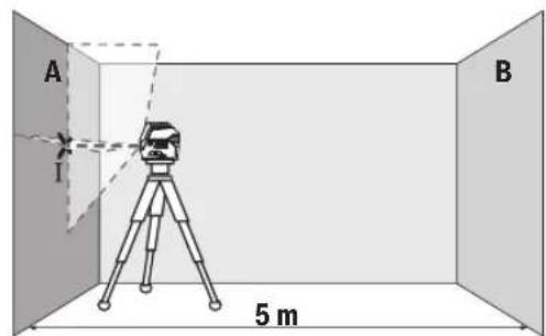
- aonmgon mgbmo ygbmgl 3gogmo A gos
aogbo n bsma bmbusymyo 0nno6nmoqdool
agudmgommo. amnabgo msbgymo lbogdo1
ooos330nnl 856mo (gmo)
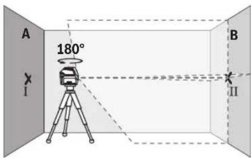
- amsbmy6g bsmdn bgsusygm 180°-u, gos
aogon nn slu 3nna6oanmngdo n agusdmoa
am66gon mssgyma n bsjdo u ooc3cnn
fogomn dn3nogos3nog 3wogB B (gogno II). - aanssugan bsmaa bocssyam - amo6golu 0000000000000000000000000000000000000000000000000000000000

- aomn6000000000000000000000000000000000000000000000000000000000000000000000000000000000000000000000000
-8s6mgo gomol mombol undogng.
dunusmoosooosooosbnooosmonn:
snuomou mndanu onssmogx03a/
ssmmoo: 36nu mnmu uodsmu oom2 a
duusmoosooosooos
2x2a x0,3 a/8=±1,2 a. sdoom
gmoangon III GS IV y6oos agosmogoglu
dsdnoaggs 6s3mgon 1,2 aodnssgnonss5.
aagmabunyymnabqamgbs
dDgDgDgDgDgDgDgDgDgDgDgDgDgDgDgDgDgDgDgDgDgDgDgDgDgDgDgDgDgDgDgDgDgDgDgDgDgDgDgDgDgDgDgDgDgDgDgDgDgDgD
-ooosagmno Iobman bcmusyym Lssmy 5 ssasg8g
(14)00000000036g. sahogon
ymoommsb no gndn oos angnno bcmusymb
6o3gmngndu gudmgdmos.
-688g 6060600800000000000000000000000000000000000000000000000000000
60606060606060606060606060606060606060606060606060606060606060606060606060606060606060606060606060606
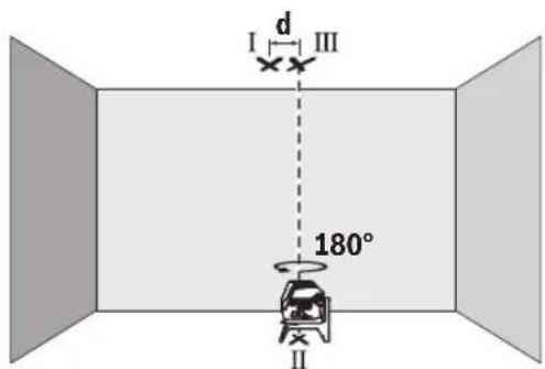
www.bosch-pt.com/serviceaddresses
yGnno8b0s
usbman bngusyymgon, sgluygmon gos 003j03s
oossymon gomdumonab yogmombn.
sAsysyamnUsmdn bgyuymgonos
SgymgonUsymgmbgm
6m860056 gmonso!
Româna
Instruţiuni de siguranta

Service scule electric
Strada Horia Macelariu Nr. 30-34, sector 1
013937 Bucuresti
www.bosch-pt.com/serviceaddresses
Eliminarea
Aparatele de māsūrā, accesoriile ši ambalajele trebuie directionate cātre o statie de revalorificare ecologica.
ToykOB mIHeen naep GCL 2-15 GCL 2-15 G
Bn3aunitaIP54(3aunita cpeuy npoHKBaHe Ha
IpaX HAnPbCKBaHe C BOa)
IP54 (3aunTa cpeu npOnnKBaHe Ha
npax HnapbckBaHe c Boda)
A)Пин He6naTOnPnTHn YcNoBn (Hanp. HnOncpeCTBeHn CbHbYeBn bHy) paOToHnT dHa nAna3OH MoKe Ja e No-MaIbK.
B) npn 20-25°C
C) NocoueHHTe CTOHOCTH INpEINONAR HOpMaINH NO 6nAoropmTnH yCIOBn HA OKoIHATA Cpea (HaNP. 6e3 Bn6paH, 6e3MbIa, 6e3dMM. 6e3 dneKTHO cBHeBO bYeHHe). CnED CNHH TEmNepaTyPH KOne6AHn MOKe Da Ce TnHRe Do OTKnHOEHn B ToHOCTTa.
D) Ima caMo HEnpoBOMMo 3aMbpcBaHe, npn KoToe o6aue e Bb3MOKHO da oe aOKBa BpeMeHNO pnpHHeHa npoBOIMoc T npaHIO KOHeH. 3a eHNo3aHNo HEnTHnOuHpaHe Na BaHna H3MepBaTeNeH ypeN cnyKcn cepHHrHt HOpE (12) Ha TaBeNKaTa Hypda.
MOnTupahe
H3non3BaHe/cmHa Ha 6aTepuNTe
3a3axpaHbAe Ha 3MepBaTeHHy ypeI ce npenopbBa H3- non3BaHeTo Ha aKanHO-MaHraHOBn 6aTePN.
3a OTBaprHe Ha KaNaka Ha rhe3dTo 3a 6aTepeHn (6)HaTnCHeTe 3actOnopraBaun 6yToH (7) HOTbOpTe KaNaka Harope. IocTabete 6atepnnte.
BHHMaBaIte 3a IpaBnHnHaTc NnonpHoc, H06pa3eHa Ha fHiypata OT BbTpewHATA CtpaHa HA rHe3DoTo 3a 6aTePN.
Ako 6atepHnte ce n3ToaI, npdynpkdeHneTo 3a
6atepHn (2) MraB3eJeHo. OCBHe TOBa na3epHnte HnHH
Mrrat Ha BceKn 10 min 3a npHb.5 s. Ot hauano To Ha mHa
HEto H3MEpBaTeHNHType MoKe da pa6oTH oue npHb.
1h.Korato6atepHnTeceH3TOUAT,HeNOCpeIcTBeHO npedn ABtOMaTHHOTIO3KIIuOyBaHeHa3MePbATEHnYpeI na- 3epHnTeINHHMIRATOTHOBO.
3aMeHnTE BnHaRn BCnKn 6atePnn eNHOpeMeHHo. N3noJI3BaTe BnHaRn 6atePnn OT eINH n CbU npOn3BOJTe N c eHnKaBb KanaTET.
Ako npoDbIxHTeHNO BpeMe Hma Da n3non3BaTe HcTpymenta, h3Baxdaite 6atepnte ot Hero. PnpO-DbIxHTeHNO CbXpaHraBe H Hea 6atepnte B n3mepaTeHHNn HhCTpyMeT Moar da KopoDnpat N da ce camopapaeT.
IeHocn C BbpTaaTa Ce cToKa RM 1 (Bk. fnr. A1-A3)
C NOMOHTa Ha BbPTAA ATA CE CTOnKa (14) MoKTe Da 3aBbPtATE H3MEpBaTeHnHa ypeD Ha 360^ OKoIeHTpaJIHa, BnHaTn BnIMMa OTBeCHA TOka. Taka Na3ePHTe NHHMORat Da 6bDat No3NIOHnPAHnTOH0, 6e3 Da 6bDe npOMEHHa no3NtAHa H3MEpBaTeHnHa ypeD.
IocTaBete H3MepBaTeHnHnypeD CBODeuHa KaHa1 (8) Bbp-xy HnPaBnBaUaTAtuHa (15) Ha BbptAuta Ce CTOnKa (14) H BKapaiTe H3MepBaTeHnHnypeD Do ynop B nlaTphiOpMaTata.
3a demontpahene n3dbpnaTe n3MepBaTeHHypeoT BbpTAAata ceToKaBnptOBNOJOKHnOcoka.
Bb3MOKHOCTH3aNo3nUOHOHPaHEHa BbPTAata ce cTOnKa: -noCTaBeHa Bbpxy paBA HOBbpxHOCT,
-3aXBaHaTa C BnHTOBe KbM BepTnKaHnA IOBbpxHOCT,,
-BKOM6HHaHcBcCKo6aTa3aTaBaHN(18)KbMMeTaNHaNCHHaTaBAHn,
C NOMOHTa Ha MarHHTte (17) KbM MTeAINHIOBbpXHOC-
PnHADNEKHO3pKpENBaHe HnOcneHATA KbM NOBbpxHOCT. Upe3 CnHATA pnterna CnHa Ha MaHNITTE PbCTHTe Bn Morat da Ce 3axBaHAT.
Pa6ota
Iyckahe B eKcnnoataua
PpeNa3BaIte H3MePbATEHnnp6OpOTOBnaxnBaHe INDPeKTHO NOnaHaHE NaBHeBnIbN.
He n3naraate H3mepeBATEHnna ypeHaekCTpeHHn TEMnepaTpyn nn pe3KN TemnpaTpyn npomenn.
Hanp. He ro octabnIte npOdbnKntenHO BpeMe BAETOMo-6nn. Pnri ronem TEmnpaTyPhN KOlebaHn OCTaBnTe n3MepBaTeHHn ypeJ da ce aanTnpa H npEi npOdbKaBaHe Ha paboTa BnHaRn H3BbPbWbAte NpOBepKa Ha ToUHocTtA (Bk. IpoBepKa 3a ToUHocT ha N3MepBaTeHHn ypeD, CtpaHnca 197).
PnEckTepeMHN TEmpeaTpH NnI rOeMH TEmpeaTpHn pa3JIHKN TOUHOCTTa Ha H3MePbTeJHHypeM OKeJa ce BNOHN.
N36BBAIe CnHn yApn Hn H3nycKaHe Ha N3MepBaTeHHype. Cne yapHn Bb3JeCTBn Bbpxu N3MepBaTeHHype Tp8Ba Da n3BbpWBe pNoBepKa Ha TouHOCTa My, Pepn Da npOdbJXKeT Da ro H3non3BaTe (BXK. "PpOBepKa 3a ToOHcT Ha N3MepBaTeHHn ype", CtpaHn-197).
Korato npehacate ypeda, npedbapntenho ro h3knouBaTe. PnH3KnUcBaHe MoyIbT 3a Kone6aTeHN DBNJKeHHce 3aCTOnOpRABa, Tb KaTo npn CInHn B6paunMoKe da 6bde Nobpehen.
BknIOuBaHe n H3KIOUoBaHe
3a BKNIOUbaHe Ha N3MepBaTeHNHrypeI npMeCteTe nycKOBn PpeKcbBauch (9)do No3NHTaOn (3a DeHOCTH C MaXaHNO apETnpaHe) HNN do No3NHTaOn (3a DeHOCTH C ABTOMATNUHO HNBENPAHe).BEnHara cneD BKNIOUbaHe N3-MepBaTeHNHrypeI hNbUba Na3ePHN Ibyn npesOTBOPHTe (1).
He haooubaTe na3epHnI NbKbM Xopa Hnn KKNBOTHN; He rnaTe cpeuy na3epHnI NbU,cbuO nOT rONMO pa3ctoHHne.
3a nKIOUbaHe Ha n3MePbATEHnHn HnCTpyMeHT npMeCeTe neyckOBnIpeKbCBau (9) B no3nue Off. Pnp n3KIOUBAHe moynbT 3a Kone6aTeHNHte DnHexeHnCe 6nOKupa.
He octabTte ypeDa BkIIOueH 6e3 HAp3Op; cne KaTo npKIOUHTe pa6ota, ro N3KIOUBAITE. IpyrNnua Mo- rata 6bDat 3acnenenH ot na3epnna lyu.
Pn npemHHaBe Ha MaKcHmAnHO DoNcyTmMaTa TemnepaTy pa ot 50°C ypeBt ce nKJIIOUBA 3a npEJa3BaHe Ha na3epHnHaIOD. CneI oxJaDaHe N3MePBateHNHT ype e OTHOB roTOB 3a pa6oTa H MoKe da 6bDe BKIOUeH.
ABTomaTHH0 H3K1HO4BaHe
Ako 3a np6bn.120 MNHTn He 6bde HaNTCHat 6ytoH Ha n3MepBaTeHHnry ypeD, 3a npedeNa3BaHe Ha 6aTePNrte N3MepBaTeHNHrt ypeD ce H3KNIOU4Ba ABToMaTHNo.
3a da BkHouHe NOBTOPO H3MepBaTeHNHa ypeI cneI aBTOMaTHUHO N3KIOUBAHe, MOXeTe Da N36byate NycOBnI pKeBcBau (9)MbPO Ha N03uNHA "Off" H cneI TOBA OTHObO da BkHouHe N3MepBaTeHNHa ypeI hIN Da HATNCHEte 6yToHa 3a peKHM Ha pa6oTa Na3epHa ToKa (4) INI 6yToHa 3a peKHM Ha pa6oTa Na3epHa LInHNA (5).
BpeMeHNO DeakTHBnpaHe Ha aBTOMaTHUHOTO n3KIIIOuBaHe
3a da deakTNBnpeAte ABOMaTHUHO tKNIQBaHe, HATNCHe T 3aDpBxTe NOhe 3 cekyHn6byToHa 3a peXHM Ha pa6ota Na3epHa NHHN (5) (npn BKNIOueH n3MePbATEeH ypeI). PnDdeakTNBnpeHa Ha ABTOMaTHUHO tKNIQBaHe Na3epHnTE NHHN pinnmRbAT KpaTko 3a NOTBbPjXdHHe.
Yka3aHHe: Ako pa6oTHaTa TemnepaTpa HAdxBpIn 45°C, aBtOMaTHUHOTo I3KNIQUBaHe He MOKe da 6bJe DeakTNBpuHO.
3a da aKTHBnPaTe aBTOMaTHUHOTo H3KNIOuBaHe, H3KNIOUeTe HOTHOBO BKIOUeTe H3MepBaTeHnHpyed.
H36op ha pexkma ha pa60Ta
Ja3epHnHT ypeJ pa3IOna r c HAKONK pa6OTHn paBHNm, MeXy KOHTO MOKeTe Da IpeBKIOvBaTe NO BCAno BpeMe:
-PexHM Ha KpbctocAH NHHH NTOUka: 3MepBaTeHNH-RTypeI reHepeipa edHa xOpH3OHTaHnHa nEdHa BepTKaIHa na3epHN HnHn HAnpei, KaKTo I No eHa Na3epHa ToKa Harope HnHdony. Na3epHnTe LHHn Ce npeChuT noBb190°
-PexkmXopn3oHTanhaNNHn:HmepBaTeHHnTypeDHe npa eHaXopn3oHTaHaNa3ePhaNNHn Hanpe.
-PexHM BePTKanHa NHHN: H3MepBaTeHnHT ypeI reHe-pnpa edHa BeptKanHa Na3epHa NHHn HaNPeI. Pn noCTaBHe Ha H3MepBaTeHnHa ypeI Ha TaBaHa BeP-THKaANHaTa Na3epHa NHHN ce H3Nb4Ba Ipe3 rOpHata Na3epHa TOka.
NoctabHHe Ha 3MepBateHnHpyed HenocpeDCTBeHOHa CTeHa BepTikaiHata na3epHa nnHnreHepnpa eHa noTu 3aTbOpeHa o6KoHnHa na3epHa nHHra (360^ HnHna).
-PexKM ToKa: H3MepBaTeHnHrTypeI reHepnpaNo eHaToKa Harope HADOny.
BcnKn peKIMn Cn3KnOueHHe Ha TOOKOBnpeKIM MoRat Da 6bDat N3No13BaHN KaTc a BtOMaTHUHO HNBENHpAHe, TaKa n C maxanho apetnpahe.
Pa6ota cbc cnCTemata 3a ABTomaTHNO HHBENHPaNe
| Последователноct на pa6obtнite сълки Ржимхор- зонтална линь нima | Ржим вети- Кална линь | Ржим точka Иndида maxan- но.apетеране(3) | Фиура |
| Пусков пекьсвач (9)В поэция "н" | ●●● | B1 | |
| Ржим крьстocationи линь | |||
| +Нат SCHEТЕ 1×6уToha за ржим на pa6ota пазерна линь (5) | ●-● | C1 | |
| Нат SCHEТЕ 2×6уToha за ржим на pa6ota пазерна линь (5) | -●● | D1 | |
| Нат SCHEТЕ 3×6уToha за ржим на pa6ota пazерна линь (5) | - - ● | E1 | |
| Нат SCHEТЕ 4×6уToha за ржим на pa6ota пazерна линь (5) | ●●● | B1 | |
| Ржим крьстocationи линь | |||
| Неша ВИСМО OT ИЗбразни ржим за линнente може за bdeakTNВпоган лinn DeakTNВпоган ржим точka: | |||
| +Нат SCHEТЕ 1×6уToha за ржим на pa6ota пazерна точka (4) | ●/-●/- | ||
| Нат SCHEТЕ 2×6уToha за ржим на pa6ota пazерна точka (4) | ●/-●/-● | ||
AkoH3MepBaTeHHrTypeE H3BbH DnHaNa3OHa 3a ABToMaTHUHO HnBeNIPAHe, Na3epHHTe NnHn NnNa3epHHTe TouKNMIRAT6bp30.
Ako,doKaTo pa6oHTe c aBtOMaTHNo HbENHpaHe, npemnHete BpeKm"Pa6oTa C maxaIHO HbENHpaHe"(nycKBOpKbCBaU (9)Ha I03uNn), ce AKTNbpa BnHaTn IbPbBaTakOMbHaun HA HnDkATOpHTe Ha To3n peKm.
IeHHocTc mMaxaHno apetHaPe
| Посnéдователноct на paбOTнITE сълки Ржимхор- зонтална линь нima | Ржим Берн- Кална линь | Ржим точka Иndицая maxan- но.apетиране(3) | Фиура |
| Пусков пекьсвач(9)В поэция""On" | ●●- | F1 | |
| Ржим крьстocationа линь | F1 | ||
| +Натснete 1×6утона за ржим на разота пазерна линь(5) | ●-● | F1 | |
| Натснete 2×6утона за ржим на разота пазерна линь(5) | -●- | F1 | |
| Натснete 3×6утона за ржим на разота пазерна линь(5) | ●●- | F1 | |
| Ржим Крьстocationа линь | F1 |
BpeKmPapota c maxaHNo apetnpaHe"na3epHnTe nHHMrrat noctoHHo 6abEH TaKT.
Ako,doKaTo pa6oTHe cABtOMaTHUHO HnBEnHpaHe, npemHe T BpeKIM "Pa6oTa C ABtOMaTHUHO HnBEnHpaHe" (NyckOB npekbCBAu (9) HaNo3nue n), ceakTNbnpa BNHaI mPbBATA KOMbHaunr Ha HnDnKaTOPHe Ha To3n peKIM.
ABTomathno HnBennpahe
Pa6ota cABTOMATHNO HHBENPAAE (BXK.ΦHR.B1-E1)
IocTaBeTe H3MepBaTeHnHa ypeHa TbBpda XOpH3oHTaHa OCHOBa HINr MOHTnPaTKe KbMBbPTAaTaCe pbKoXBaTKa (14).
3a da pa6oHTe caBOMaTHUHO HMBenHpaHe, NOCTaBeTe nycKOBnIpeKbCBaH (9) B no3uNur "
CnCTemata 3a ABOMATUHO HNBENIPAHE KOMNEHCIPA OTKIOHEHNAOTXOUPN3OHATABpAMKHTeHaDnAHAOHA3aABTOMATUHO HNBENIPAeOT ± 4^ .ABOTMAHTUHOTHO HNBENPAHHe npNKIOUHNO, KORATO NAZEPHNTIbY CNpaT DA MHRat.
Ako aTOMaTHHOTHO HHeJIHpAHe He e Bb3MOxHO, HAp. KOrato NOBbPxHOCTTa, HA KOrTO ypeIbTe nOCTaBeH, Ce OTKIOHRABa OXOpH3OHTaIATA NOBcye O4°, Na3ePHNte IHHn 3aNooyBaTda MmRat6bp30.
B TaKb CnyaH noCTabE H3MepBaTeHNH ypeD xOpNHO tALHO H3yakaHte ABTomATnHOTo MY HnBeHnPapaHe. Korato H3MepBaTeHNHtYpeD 6bDe NoCTaBEH B rpaHnHTe Ha dHa na3OHa 3a ABTomAtuHnBeHnPapaHe OT ±4°, Na3epHnTe Ib-yn 3aONuBAT da CBETT HenpeKbCHATO.
Pn pa3tpcbHn Hn npomHa Ha noIooKeHneTo NO BpeMe Ha pa6ota n3MepBaTeHNHT ypeD CE HNBEnIPA oTHOBO aBTOmatuHO. Cne npKNUOVAhe Ha HNBEnPAHETPO3NtA Ha na3ePHNTIbUH NO OTHoUHe Ha pepepENTH ToUK, 3a Da n36ErHete rpeuKn BCNECTBHe Ha OTMeCTBaHe Ha ypeDa.
DeHHocTc maxaHNo apetnpae (Bx. qHr.F1)
3a da pa6oHTe C maxaHno apetnpaHe, noCTabeTe nycKOBn npekbCbau (9) B no3nuaon". HndkaunraTa 3a MaxaHno apetnpaHe (3) CBETBa B cepBeHo H na3epHnTe HnHH Mmrat NoctOHHo 6abHO.
Pnpa60ta c maxaHnO apetnpaHe aBOMatnHOTn HnBe nIpaHe e n3KnIOueHo. MoKeTe da bpxNte h3MepBaTeHNHa yed cbo6oHO B pKa nn Da fo nocTaBHe Bpxy HaKNOHe Ha NobpXHO TApEPhne lyu Beue He ca HnBEnpaHn H e 3aNbJnxTeHNo Da npemHaBabT OBeCHO Ea npyra.
PpOBepKa 3a TouHcT Ha H3MePbTeHNnYpe
ΦaKTOpH, BnIReuHa ToUHocTtA
Hai-rotanMO BnHHe Bbpxy ToOHCTHa HMa OKoHata TempeIpya.CneuaHNO TemepaTpyHaTa pa3nHa oT noa Harope MoKe Da IpEIN3BnKa OTKNoHEHH HaJa3ePHnIbU.
3a MHHMHMnHaPe Ha TepMmHn BnHnO THaHnAa Ce O TNOa TOIINHa,Ce npenopbUba H3N03BaHeTo Ha N3MePBATeHNy ypeB Bpxy CtaTb.OCBeH TOBa pRn B3MOxHOCT BnHarn NoCTABnTE H3MePBAeHNy ypeB CpeDaHa pa6oTHaTa nNou.
HapecBbHnHHe pKaTOpn, npuHa 3a oTKnoHnMOrat da6bDat cbso n paKToPn, Cbbp3aHn Cypea (HaNP. NaDAne HnnCnHn Bn6paunydpn).3aTOBa BnHnHn npEiNzaoVbaHe Ha pa6ota npOBepBaIte ToHocTTa Ha HbEnnpahe.
BnHaHn NpBo npOBepBaIte ToUHocTt Ha BnCOnHAta Hn HnBeInPapHe Ha XOpN3OHTaIIHATA Na3epHa IINHn, CnE TOBa TOHOCTa Ha HnBeInPapHe Ha BepTNKaIIHATA Na3epHa IINHn. AKn pNn HkKoR OT npOBepKITE N3MepBaTeHNrYpeHnX-BbPNI MaKcHmAlHO DOnyCTHMOTo OTKnIOHeHne, ToI Tp86Ba Da 6bde peMOHTnpaH B OToP3uPAH cepBn3a eNeKTPOINHCTpyMeHTn Ha Bosch.
PpOBepKa HA ToUHOCCTTA H BNCouHHATA Ha XOpH3OHTaHATA JINHH
3a npOBePKata TpRA6Ba DA HMaTe CBO6OHa 3OHa 3a H3MePBAHe C TBbPa OCHOBa CDbIaHnA 5 m MeKdy DBe CTEHN A B.
-MoHTnpaTe H3MePbATEHnHa ype6Ibn3O do cteHaA Ha CTaN Bn IIO NOCTaBe Tbpxy TBbpda paBaHnOBbpx HOCT. BkIOUcTe H3MePbATEHnHa ypeD.N36pepe pexm Ha KpbCTocAHnHHnC aBTOMaTHuHO HNBepnPaHe.
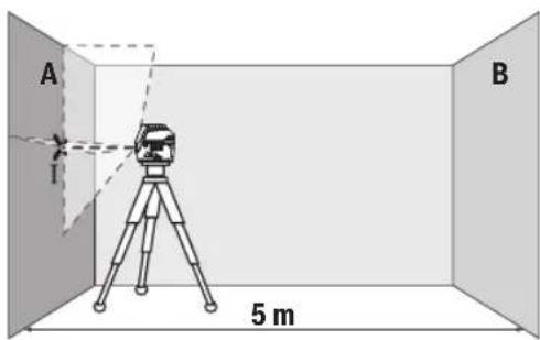
-HacoueTe na3epa KbM 6nH3kata CteHa A nTo H3uKaJTe Da ce HNBenipa. MapKnpaIte cpeJata Ha npceeuHaTotaokaHa DBeTe na3epHn NHHn (TOka1).
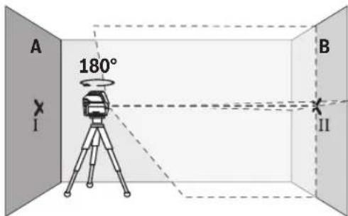
-3aBbpteteH3MepBaTeHHypeHa 180°,H3uKaJte Ro Da Ce HNBENIPA aBtOMaTHUHO I MapKnpaIte npeceHata TOka Ha DBeTe Na3epHN LInHH Bbpx Cyehata B (TouKa II).
-IOCTaBete H3MepBaTeJIHHy ypeI -6e3 da ro BbptHte 6n3o do cTeHata B, BKIOUcTe ro n octaBeTe da ce HnBENIPA.
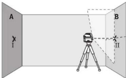
I3MeCTe I3MEpBaTeINHnY ypeN NO BnCOUHa (ype3 cTbBA Hn PnH Heo6xOHNMOCT C NoJNaRaHE), TaKaYe pceCuHATA TOUKA Ha Na3epHnTE bHy Da NOnaDa TOUHO Bbpxy MapKnpaHATA npeDn TOBa TOU Ka II Ha CTeHATA B.
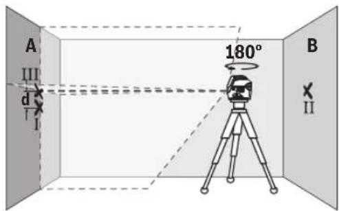
-3aBbptete N3MepBaTeHnHa ypeHa 180°,6e3 da npomeHnTe BnCOuHnHa. Hacoetee Ro KbM CTehata A Taka, yeBePTNkAJIHATA Na3epHa IINHn Da npemHnaba npe3 MapKnpaHATA npedToBA TOka I. N3uKaaiTe N3MepBaTeHnIyTpeD a ce HnBeHnPa Ha MapKnpaTe npeceHaTa TOkaHa Na3epHnTe JbCuHa CTehata A (TOka III).
-Pa3nKkata d MeKJy DBeTe MapKnpaHn TouKn I I I I HA CTeHATA A DaBa DeIcTBInTeHOTo OTKIOHeHne NO BnCOuHa HaN3MepBaTeHNHrypeI.
Ha pa3ctOaHHe O T 2 × 5 m = 10 m MaKcHMaJIHO DOyCTMnO-TO OTKnOHeHHe e:
10m×±0,3mm/m=±3mm.CneOBoTeHNO pa3Nkata d Mekdy ToKHTe I N III Tp8Ba Da e HaH-MHOrO 3 mm.
PpOBepKa Ha ToUHocTtHa HnBEnHpAne Ha XOpH3OHTaJIHATA JHHN
3a npOBepkata ce Hxkaete ot CBO6oHa nlou ot np6n. 5× 5m
-MoHTnpaTe n3MepeBateHnHnypeD B cpeDATA MeKdy CteHnTE A N B BBpy CTATNB INI FO NOCTABETe BBpy 3dpabaPaBa HcOHOBA.N36epete peXm XOpN3OTHa INHHnC aBTOMaTHUHO HnBeHnPaHE NnBeHnPaTe n3MepeBATEHnHnypeD.
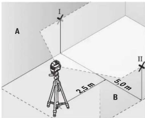
-MapknpaTe cpeTa Ha na3epHata HnHnHa DBeTe CteHN Ha pa3ctOraHne OT na3epHnHa ypeD no 2,5 m (toKa I Ha CTehA N TOUka II HA CTehA B).
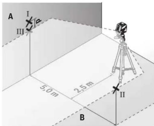
-3aBbPTeTe H3MepBaTeHnHa ypeHa 180°,noCTaBeTe ro Ha pa3cTOrHHe 5 m n H3uKaaiTe Da ce HnBEnHpa.
I3MeCTe I3MEpBaTeHnHryyepeNoBnCOuHa(pe3cTaTHBa Hn PnHneOxOHNMOCTCnoNpaHepaHa Ha na3ePHNbUda nonadHe TOHO BbpXy MapKnpaHata npEn ToBA TouKa II HA cTehata B.
-MapknpaTe Ha cTeHata A cpeHa ha na3epHata nnHnKa KATO TOyKa III (TOUHO Hd, peCn. nOJ TOKAt).
-Pa3nKata d MeKdy DBeTe MapKnpaHn TouKn I I I HA CTeHaT A DaBa DeIcTBnE HTO OTKIOHeHne Ha N3MepBaTeHNy yPeD OT BODOpBAHATA nnHna.
Ha paactoHHe or 2 × 5 m = 10 m MaKcHMaJIHO DOIpyCTHMO-TO OTKIOHeHHe e:
10m×±0,3mm/m=±3mm.CnEOBATEHOpa3NIKAtad MEXdy TOOKIe I N III Tp8Ba Da e HAI-MHORO 3 mm.
PpOBepKa Ha ToHOCCTTa Ha HNBenHpAe BbB BepTKaIHO HanpaBHeHne
3a npOBepkata ce HxKdaeTe OTBOP Ha BpTa, npN KOrTo (Bbpxy TBbpda OCHOba) HMa HauMakno no 2,5 m Cbo6oHa nloou OT DBeTe CTpaHn.
-IOCTaBete H3MepBaTeJIHHy ypeJ ha pa3ctOJIHne 2,5 m ot OTbopa Ha BpataHa TBbpda, paBH aOCHOBa (He Ha CTaTHB). H36peTe peXHM Ha BEpTKaJIH aINHHc aABTomaTHUHO HNBENpaHe. HacouTe Ia3epHATAIHHN KbM BpTaTAta H3uKaJIte H3MepBaTeJIHHYypeJ da ce HNBENpa ABTOMATNUHO.

-MapknpaTe cpeTata Ha BepTKaHATA naeepHa mHHnHa nOda Ha OTbopa Ha Bpata (Toka I), Ha pa3ctoHHe 5 m OTdpyraCTpaHa Ha OTbopa Ha Bpata (Toka II), KaKTo HHa rOpHnPa b6 Ha OTbopa Ha Bpata (Toka III).
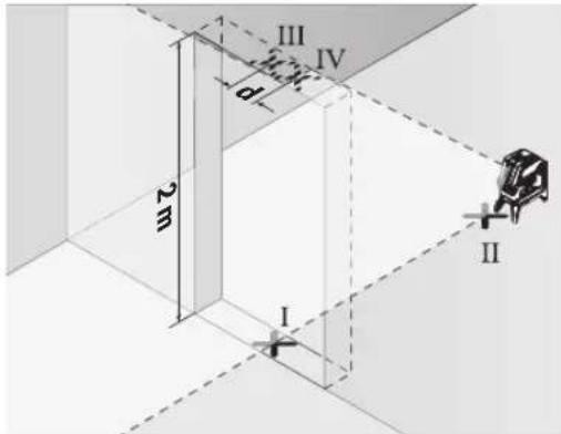
-3aBbpteteH3MepBateHIny ypeHa 180° nTo noctabeTe OT Dpyrata CtpaHa Ha OTBopa 3a BpTa HENOCpeCTBeHO 3aTouka II. N34aKaIte H3MepBateHInrY ypeDa Ce HINBEInpa HACOHTe BepTKaHnHa Ta Na3epHa INHHra Taka, Ye cpeDAta N Da MNHaba Npe3 TouKnte I nII.
- OtbeJeTe cpeTa Ha IaIepHaT a IHHnHa rOpHn p6 H aOTbopa 3a BpTa KaTo ToukA IV.
-Pa3nKkata d Mekdy BBeTe MapKnpaHn TouKn III IV daBa DeNCTBHTENHOTO OTKIOHeHne NO BNCouHn Ha N3MepBaTeHHypeJ.
-ИзмеретьионотаHaOTbopaHaBpata.
MaKcHMaJIHO DoNcyTmOTo OTKIOHeHne MoXeTe Da H3UHCnH- Te NO CLEHNHaUNH:
ДВaПБТи BHCQUHnHaTa Ha BpaTAta × 0,3mm / m ПрМер:Ппи BHCQUHnHa Ha BpaTATAOT2mMaKcHMaIHOto
OTKIOHeHne MoXe Da 6bNe
2× 2m× ± 0,3mm / m = ± 1,2mm .CneioBateHToUKHe III IV moKe da ca ha pa3ctOraHne edHa or dpyra HnMHoro 1,2 mm.
PpOBepka Ha ToHocTHa OTBeca
3a npOBepkata ce HxkaeTe O CBO6OHa 30Ha 3a H3MePbAHe Bbpxy TBbpda OCHOBa c pa3cToHHe MeKdy NDoI Na TaBaHa npn6n.5m.
-MoHTnpaTe N3MepBaTeHnHa ypeKbMbBpTaaTa ce CToiKa (14) n ro NoCTaBeTe Ha nOda. N36epeTe TouKOB peKm H3uKaAte ABTomAtHOTo HnBeHnPaHe Ha n3-MepBaTeHnHa ypeI.
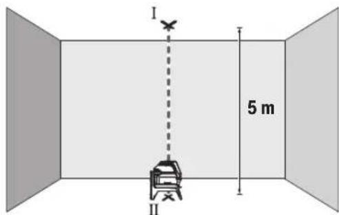
-MapKnpaTe ΒeTbpa Ha roPbTa na3epHa TOKa Ha TaBaHa (TOka I). MapKnpaTe CbTo Ka Ha NoDa ceHTbpa Ha DOnHaTa na3epHa TOKa (TOka II).

-3aBbpteteH3MepBaTeHHypeHa 180°.No3uOnOHpaIe roTaKa,ye CEHTbpbT Ha doJHATA na3epHa TOka da eTOUHO Bbpxy MapKpHaHaTa TOka II. H3aKaIte ABToMaTHNHO HnBeJInpaHe Ha H3MepBaTeHHypeI. MapKpaIte ZeHTbpa Ha rOpHAta na3epHa TOka (TOka III).
-Pa3nHKATA d MEXky DBeTe MapKnpaHn TOckn I n III Ha TaBaHa DaBa DeIcTBHTeHOTO OTKNOHeHne NO BICOCHHa Ha H3MepBaTeHNH ypeI.
MaKcIMaJIHO DOIpyCTMOTO OTKIOHeHHe MoXeTe Da H3uCnH-Te NO CNeIHnHaHn:
IBOHHTO pa3CTOHNHe MEJy NOa H TaBaHa × 0,7mm / m IpIMep:Pi np a3CToHNHe MeJy NOa H TaBaHa OT 5 m MaK-CHMJIHO TOKIOHEHHe MOKe Da 6bJe
2× 5m× ± 0,7mm / m = ± 7mm .CneIOBATEHOTOUKHTI n III moKe Da ca Ha pa3ctoHHe eHa ot Dpyra Hau-MHOrO 7 mm.
Yka3aHn 3a pa60Ta
BnHaHm MapKnpaTte cHTbpa Ha na3epHata ToKa, pecn. Ha na3epHata LHHN.C pa3ctOraHHeTO rToJeMnHaTa Ha na3epHata ToKa, pecn. Ha na3epHata LHHN ce npomehr.
Pa6oTa cbc cTaTHB (pHnHaIeXHoCT)
H3non3BaHTo HA cTaTHB OCHrypRA bCTa6HnHO, perynHypeM NO BnCOUHHa MOHTnpAHe HA H3MePbATEHNH ypeD. NocTABeTe H3MEPbATEHNH ypeD C 1/4" NOCTaKBATA 3a CTaHB (10) Bbpxy PnCBeHNHTENH BnHT HA CTaHB (23) HnHaOBHKHOBEH TPNHOXHK 3a FOToanapat. 3a MoHTnpaHTo KBm CTaHApTeH CTPOHTeH TPHOHXHK H3NON3BaIte 5/8" NOCTaKBATA 3a CTaHB (11). 3aterHe t H3MePbATEHNH ypeC BnHTA Ha cTaTBA.
IpeDn Da BkHIOUHTe H3MePBATeHHa ypei, HAcOyTe cTaTHBa rpy6o.
MOnTHnpaHc yHHBepcaHATA cTouKa (npHHaJIeXHOCT) (BHXTeΦHr.G)
C nOMOHTa Ha yHnBepcaIHaTcToKa (19) MoKTe Da 3axBaAaTae H3MepBaTeHNHrypeHn. KbM BepTKKaHn NOBpXHOCTN, TpbNnHnHAMarHeTnHpaUNCe MaTePnANy.HnBepCaIIHATA cToKa e NDOxOJaCAcbTOtKa n3a NoCTaBHeHa NODa HOBNeKUaba HAcTPOBnBaHETo NO BnCOuHnHa Ha n3-MepBaTeHNHrypeN.
PnhaHnHaJIeKHOCTn.3aHATA CtpaHa Ha MarHHTHaTn pInHaIeXHcOHTn 3aKpEnBaHe Ha NocneHbTa KbM NOBbPxHcTn. Upe3 cHHa TpnterJna CnHa Ha MaHHTte npbCTnTe Bn Morat da ce 3axBaHt.
H3paBHeTe yHnBepCaHaTcStoKa (19) rpy6o, npedn da BkIOHTe H3MePBAteHNHypeD.
Pa6ota c na3ephata MepuTeHa nnoa (Bx. fHr. G)
Ja3epHata MepeTHeHa nOua (20) noo6paBa BnHmocTa Ha na3epHna ly4 npi He6naTnpnTn pa6oTHn ycNoBn I No-foEmn pa3cToHHN.
Otpa3raBaaTnOBbpXHOCTHaIa3epHATApeHtHa nloa (20)noIO6pBaBnIMOCTTHaIa3epHATAHHN, a npE3 npO3paHaTnOBbpXHOCTIa3epHATAHHN MoKe da ce BnHnOTobpaTHaCTpaHaHaIa3epHATApeHtHa nloya.
OuHnHa6nDaaHe Ha na3epHnIbU (npHnAdnEeKHOCT)
OuHaTa 3a Ha6nDaBaHe Ha Na3epHnIbUy PhHnTpPaT OKoHnata CBeTIHa. TaKa Na3epHnIbUc TcBA No-NeCHO pa3NJHm.
He 3no3BaIte Na3epHnTe Ounna (npHaadJeXhoCT) KaTo 3aunTHnOUnna. Na3epHnTe OUnna cnykat 3a noD6po pa3no3HaBaHe Ha Na3epHnra Ib? Te He npedna3BarOT Na3epHO IbYeHne.
He h3noI3BaIte na3epHnte ouHna (npHaIeNkOCT) KATO CbHueBn ouHna Hn npu oOpHpaHe. Na3epHnte ouHna He npedlaIarT PbIHa UV 3aunTa n HaMaJIaBt Bb3pPnEmaHTo Ha CBEToBeTe.
Pa6OTHn npHmepn (Bx. qnr.B2-F2,GnH)
PpHmepn 3a npnIOKeHHeTo Ha nImpeBaTeHHypeN MoKeTe Da Bnnte Ha CTpaHncaTa C cnHyprte.
PoaBpKaHe n cepBn3
IopdbpxaHe n nouHCTBaHe
PdIbpxaIteH3MepeBatenHpyed BnHaHn uCT.
He nToTnBaIte H3MepBATEHnHa ypei BbB BOa nn Dpytn TeuHOCTN.
N36bpcBaeTcAmbpcBaHnraTaC MeKa,NeKo HABNaXHeHa Kbpna.He n3noJ3BaTe NouchTbau npenapaHn pa3T BOpHTe.
IpoHCTBaItepeoBHO CneuaHIO NOBbpxHOCTHeHa3XO DaHa na3epHnIbU HBMaBAHTeJa He OCTaBAt BNaCnHK.
KInHeTcKa CnyX6a H KOHcyIaunr OTHoCHO yNoTe6ata
CepBn3bIe OTOBOPn Ha BbnpocHte Bn OTHOcHPOmoHTn I NOIDpbKka Ha 3akynenra OTr Bac npOyKT, KaKTo n OTHOcHO pe3epBn qactn. POKOMNoEHTHN Yeptexn HnHΦopMa-ua 3a pe3epBnTe qactn Ie OTKPneTe H a:
www.bosch-pt.com
EkntnoKocnytaOnOTHOCNoYnOte6aHaBoschue Bn NOMORHe C yOBOJCTBne npn Bbnpoc3a HauHtene npoDyKTN nTexHNTe akcecoapn.
MOn, npBnpoCn npnpopbUbaHe Ha pe3epBn qactn BnHaH nocOuBaTe 10-uaPpeHraKaTaoXeH HOpE, n3nHcA H TaBeKkata Ha ypda.
BbIraPna
Robert Bosch SRL
Service scule electric
Strada Horia Macelariu Nr. 30-34, sector 1
013937 Bucuresti, Romania
TeN.: +359(0)700 13667 (bblrapckn)
ΦaKc: +40 212 331 313
Email: BoschServiceCenterBG@ro.bosch.com
www.bosch-pt.com/bg/bg/
DpyrH cepBn3Hn apecn uie otKpneTe Ha:
www.bosch-pt.com/serviceaddresses
BpaKyBaHe
I3mepBaTeHNHrTyei,IOJIbIHInTeHNHrTe pncnOc6neHn ONAKOBKHe Tp86Ba Da 6bDat NIOJNOKeHN Ha ekOJOrnHa npepa6OTka 3a ycBOBaHe Ha cbdbpxaunTe Ce B TIX cypoBHH.
He n3XbBpIaTe n3MepBaTeHnTe ypeDn H6aTePnTe npn 6ntOBnTe OTnaBu!
Cama 3a cTpaHH ot EC:
CbINaCHO eBpOeNcKa dIpeKTHBa 2012/19/EC 3a cIapITHeEeKTPnueckn H eekTPOHNypeHn HeHHTo TpaHCnOpTnPahe B HaunHOHaHOTo npABo H3MepBaTeHNrte ypeHn, KOHTo He Morat Da Ce NOn3BaT NOBeUe, a CbINaCHO eBpOeNcKa dIpeKTHBa 2006/66/EO NOBpeEHn Hn H3xa6EHn O6NKOBehn Hn AkymyNatOPHN bATEPHN, Tp8Ba Da ce cb6HpAT nIpeDaBAT 3a OnON3OTBOPBAHe Ha cbDbpxkAsHTe Ce B Tnx cypoHH.
PnHnepaBnHO hXbBpIYe CTapHe eNEKtpueckn H eNEKtpoHHN ypei NiopadN Bb3MOxHOTo HAnuNe HaOnaCH N BeIeCTBa MOrat Da OKaKaT BpeHN BInraHn BbpxOkONHa- Ta CpeaH NoBeWkoTo 3dpaBe.
MaKeDoHcKn
Бe36eДнocHn HanomeHH

Ctye yntCTBa Tpe6a Da ce npouHTaaT n da ce BHHMABA Ha HNB, 3a Da MoKe 6e36eHNO H 6e3 onachocT Da pa6oHTte co MePHNOType.Дokonky MePHNOType He ce
KOpHCTN corIaCHO npHIOXeHHTe HnCTpyKunH, MoKe da ce HApUH ΦyHKunjata Ha BrpaJeHHTe 3aWHTTHMexAH3MH BO MePHNO TyeJ. He rOwTeYbajte HaneHHuTHe 3a npdeynpeyBahe. IO6PO yBAJTE OBNE YIATCTBA N PPEDAETE Tn 3AEHO CO MEPHNO TyeJ.
BHHMaHHe -DOKKky KOpHCTNe Dpyr Hyei 3a NOdecyBaBe H paKyBaBe OCBeH OBDe HabeJeHHTe NNNONHAKNIOCTaNKn, OBA MOKe Da DOBeE Do ONaCHA H3NoXeHOCT Ha 3paueHe.
MepHnOTypeCeHCnpaUyBaCo03HaKa3a npedynpdyBaBe 3a nacepot (O3NaeHo Ha pNkA3OT Ha MEPHnOTypeHa rpaΦnKATAcTpHa).
Dokonky TeKcTHa 03HaKaTa 3a npEynpeyBaHe 3a nacepot He e Ha BaHnot ja3NK, Bp3 Hero 3anenete ja HanenHnqata Ha BaHnot ja3NK nped npBata ynotpe6a.
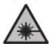
He ro hacouybaje Iacepcknot 3pak KOH
IIua Hnn XHBOTn HEmoJte N Bne camnte
da rnaTe BO dpeKTHnoT Hn
pePneKTHpaUcKnot Iacepckn 3pak. TaKa
MOKe Da rH 3acnEnIte HncaTa, da
IpeIN3BnKate HecepeKn Hn Da rN OWTHTe
OHTe.
Dokonky nacepckhot 3pak docnee do ouhte, Behdaw Tpe6a da rH 3aTbOpHTe H da ja TprHete rnaBata od nacepckhot 3pak.
He npaBeTe npoMeHH Ha nacepckHOTypeI.
He Hn Kopncte Nacepcknte 3aunTHN Ounna (DononHntenHa onpeMa) Kako 3aunTHN OUnna. Nacepcknte 3aunTHN Oounna cnlykata nnoDoppo paacno3HaBaHbHa Naacepcknot 3paK; cenak, Tne He WHTAT od Nacepckto 3pauehe.
He rKopnCTeIacepcknte3aHTTHOcHna (DononHnTeHa onpeMa) kako Ounla 3a COHue Hn nak Bo coo6paKaJot. Iacepcknte Ounla He daBaat cenocha UV-3aHTTa ng Ha ManyBaat npeno3HaBaHbeto Ha 60n.
MepHnOypeIcMeeJaCe nonpaba cMo oI cTpaHa Ha KBaIIHfKByBa nCTpyeH nepcoHan I cMo co
OpHnHaHnpe3epBnHdNoBN.CaHO Ha ToJ Haun HKe 6nTe Cnpyn BO 6e36eHocTa HA MepHnoT ypeI.
He n octabajea Ta Ra KOpHCTat NacepckHot Mepeh ype6e3 HAp3Op. Be3 Ha3Op, Tne MoKe da ce 3acnenat ce6ecn nn npyri nna.
He pa6oTe co MepHnot ypeB OOKoHnHa Kaede nocToH onaChOCT oEKCnNo3Ja, KaDe HMa 3anaHbN TeuHcTH, rac Hn npaHnHa. MepHnot ypeD co3daBa NCKPN, KOn MOKe da ja 3anaNat npaBA tnn napeata.

He npnHecyBaJTe MepHnot ypeH n MarHeTHaTOnpema BO 6nn3nHa Ha mnnAHTn Hn DpyrH MeuunHckn ypeH, Ha np. nejCmejKePH Hn HhcynnHcKa nymna.
Ipeky MaHHeTne Ha MEPnOt ypei HOnpemaTa ce Ipon3BcYBa None, KOeHTO MoKe Da ja HApuyh FyHKuJaTa Ha HmPnAHTNe HmMeDnHckTe ypei.
Држete rH Мернот ypeH n MaHHTa T Onpema nOdaNeky oD MaHETn HocauH h NodaTOuH ypeH uYBCTBNTENH H aMHR. IopaIbNJIaHHeT OHa MaHETHTe OD MepHOT ypeH n OnpemATA MOKe da DoJde DO HENOBpATHN 3ary6H h NodaTOUte.
Onnc Ha npoH3B0DoT nepopmaHCNTe
BHHMaBaJTe Ha cIHKnTe BO npeHnO T dE Ha yNaTcTBOTa KOpNCteHe.
YnoTpe6a co cooDbetHa HameHa
MepHnoT ypeI e HameHET 3a OndpeyBaHe n npOBepKa Ha XOpHIOHTaIIHn BepTKaIIHn IINHH, KaKo H TOCKn Ha BepTKaIIaTa.
MepHnOT ypeI e nOroEn 3a KOpHCTeHe BO BHaTpeWeH HADBopeWeH npocToP.
Oboj npOn3BOe notpoWByaKn Iacepckn npOn3BOd Bo cornaocr co EN 50689.
Hnyctpaunja ha KOMnOHeHTN
HymepnpaBeTo Ha cInKHe Co KOMNoHEHTn Ce OndecyBaHa npka30Ha MePHNOT ypeH a rpaФuKaTc TpaHua.
(1)Излесен OTВОр заразкnotаразн.
(2)П electуразувае за ватураита.
(3)Пикадocиларогаблokада
(4) Konue 3a pejmmot Ha pa60ta Naapecpka Touka
(5) Konque 3a pekimot ha paoba Ta Nacepcka liHHja
(6) Kanak Ha npperpaata 3a 6aTepeHH
(7)ФИKKCnpaHbHaKaIaKoT Od npepradaTa 3a 6aTeepu
(8)BoDeuKxJnE6
(9)П配电инвачзыклuyваьe/ИСКлuyваьe
(10)Пинфат ha ctaTHBOT 1/4"
(11)ПифагНаCTATNBT5/8"
(12) Cepnckn 6poj
(13) Hatnnc 3a npdeynpeyBahe Ha nacepot
(14)PotaHNoHenDpKau(RM1)
(15)Шина-ворунка
(16)ИЗдолжени OTВори за пицьрстува.
(17) MarHET
(18)TabaHckca tera
(19) yHnBep3aeneHdpkaa(BM 1)a)
(20) Nacepcka ueHa Ta6naa
(21) Kypepa
(22) Bnouka
(23) CtaTnB (BT 150)a
(24) Teneckoncka npaqua (BT 350)
(25) 3aHTHTHa YaHTa
(26) Nacepckn 3aWHTNTH Ounna
a) OINHuaHATA ONPMA npHKAKAHA Na CnKNHTe He e den oCtAHdAPHHOT o6Ma HcNOPaKa. LcNoCHaT ONPMA MoKe da ja HajiTe BO Hauata Iporpama 3a onPMA.
Texnukn noaToun
Mozhnoctn 3a no3nOHHpaHe Ha potaOnHOT dpJau:
-BOIcnpaBeHaNoJox6aHa paMaHa NoBpwnHa,
-Пицвретен На Бернкальна NOВршни,
-NOBp3aHa CO TaBaHcKa Ctera (18) Ha MeTaJIHn TaBaHcKn JajCHN,
-CONOMOHaMaHHeT(17)HaMeTaHHNOBpHHH.
Држete rnpcthte noDAneky od 3aHnOTenHa MaHTATA ONPema Kora ja npHKaUyBaTe Ha NOBpHHnte. Iopadn jakata cna Ha Bneuehe Ha MaHTITE, BaHTe npCTn MoKeJa ce 3aRNaBAT.
Ynortpe6a
CtabaBeBoynotpe6a
3aHTTeTo MepHnOTypeoBnaraNnDpeKTHO H3NOxyBaBe Ha COHcEBN 3paun.
He ro n3noxybaTe MEPnHOT ypeHa ekctpemn HTEMnpaTpyn Hn TEMnpaTpyn Ocunnau. Ha np. He ro octabajTe doJro BpeMe BO aBTOMo6nTot. Pn HrOeMn TEMnpaTpyn OCunnau, OCTaBeTe Ro MEPHOT ypeI npBO Da ce akImMaTHnHa HApBaTe npOBepKa 3a ToUHOCTa CeKOraH pPeI da npOdoJIKeTe co pa6ota (BnuN KoHTPOna Ha ToUHOCTa Ha MEPHOT ypeD Ctpanua 206). PnEKCtpeMHn TEMnpaTpyn Hn TEMnpaTpyn OCunnau, npeCnHOCTa Ha MEPHOT ypeD MoKe da ce Hapuyu.
136erhybaje yapn n npebpybha ha Mehpnoytpei. Iocnnn HauBopeuH BnnaJHa Ha Mehpnoytpei, nped da ro ynotpe6nte 3a pa6ota, cekoraWn3BPwTe KOHTPOna Ha ToHOCta (BnN KoHTPOna HaToHOCTa Ha MehpnoT ypei", CtpaHnca 206).
NcknyeTe ro MEPHnOType3a Bpeme Ha TpaHCnOpTOT. Pn HcKnyBaHbTo, ce 6nOKnpa OCnnpaaykaTa eHNuca, Koja 6n ce OwTeHa npn HHTeH3NBH DnKHeBa.
BknyBaBe/HcknyBaBe
3a BknyBaHe Ha MePHHOTypeI npHTCHeTe ro npeKHyBaOT 3a BknyBaBe/HckNyBaHe (9) BO no3nJaOn (3a pa6oteBe co ocunatopHa 6lokaDa) Hn BO no3nJaOn (3a pa6oteBe co ABtOMaTHa 3a HnBeHnPaBe).BdHnNo BknyBaHbeto,MePHNOTypeI nyTa IacepCKn nnHn ON h3ne3Hrte OTbOpH (1).
He ro hacouybajte 3paKOT CBETNHa KOH Nnua nn HKNBOTHn H He nOrrnHyBaJte DnpeKTHO BO Hero,dypn HNO rONema Ondaneheoct.
3a ncknyuBaBe Ha MEPnOT ypeI npTnCHete ro npeKInHyBaOT 3a BKnyuBaBe/ncknyuBaHe (9) BO no3njuJa Off. Pn INcknyuBaBe, ocunnpaKaTa eHnHa ce 6nokupa.
He ro octabaje BknyeHnO Mepe Hye63 HaD3Op ncknyute ro no ynotpe6ata. pyrnte Nua MoKe da ce 3acnenat od nacepcknOT 3paK.
PnHaIMHyBaHe Ha HajBcOKaTa Do3BOJeha pa6OHa TeMpeApyo od 50°Ce ncknyuBa 3apaN 3aHTHa HaIacepckata DnoJa. OTKako Ke ce onaN, MepHnot ypeE IOBTOPOIOBtBe 3a pa6Ora NMOke OJHOBO Da ce Bknyu.
AbTomatkaHaHcknyuYaBahe
Iokony 120MH.He ce npHTNCHe HneHNO KOJIeHa MePHNOT ypei,ToJ ce NCKnyBa aBTOMaTcKn 3apaa 3aHTHa batepntte.
3a NOBTOHO Da rO BKnyHTe MePHNOT ypeI NO ABtOMATCKOTO NCKnyBaHBe,MOKe IIN IIN PBO da rO CTaBHTE npeKHyBaOT 3a BKnyBaHe/NCKnyBaHaBe (9) BO nO3nJia,Off' INoToa NOBTOHO Da rO BKnyHTe MePHNOT ypeI,IIIN EDHaI DA pInTCHete HA KOnTuTe 3a peKHM Ha pa60ta Nacepcka ToUka (4) IIIN HA KOnTuTe 3a peKHM Ha pa60ta Nacepcka IIHHJa (5).
JaekTNBnpaHe Ha aBTOMaTHKaTa 3a NcknyuByBaBe
3a da ja deakTNBnpaTe aBTOMaTKaTa 3a NcknyyBaHe,
dpKeTe ro npNTCHato (pnp BknyueH MepeH ype) KOHTO
3a pexHM Ha paBoTa Nacepcka nnHJa (5) Hajmky 3s.
doKoNky aBTOMaTKaTa 3a NcknyuYBaHe e DeakTNBnpaHa,
nacepCKnTe 3paun KpaTko TpeNkaat 3a NotBPda.
Hanomeha: Ako paobothata TemnepaTypa ja haDMNHyBa 45^ , aBtOMaTHKaTa 3a NCKNpyBaHe Me MoKe Da ce DeaKTbPa.
3a da ro akTNBnPaTe ABOMatCKTOH NCKnyuBaBe, NCKnyeTe ro MEPnHOTypeN NOBTOHO BKnyeTe ro.
NoecyBaHe Ha pexHmOT Ha pa60Ta
MepHnoT ypeI HMa NObEKe NaHInHa pa6Ota, KOH MoKe Da rH npOMeHHe BO 6HIO Koe Bpeme:
-PexHM H BkpcTeHN NHHH N TOckctpeXHM: MepHNO TypeN pOn3BedyBa XOpH3OHTaHa H BeptHKaJIHa Nacepcka LHHJa HaHaNPeD, KaKo H BeptHKaJIHa Nacepcka ToKa Harope H HADONY. Nacepckte NHHN CE BkpcTyBaat nod aor oJ 9
-XOpn3oHTaEN NHHNCKPexHM:MepHnoTypeI npOn3BvByaXopn3oHTaHa nacepcka NHHJa HahAnpei.
-BeptHKaJIeH NHHcKn peXHM: MepHnot ypeI npOn3BvBa BeptTKaIIHa IacepKa IIHHJa HAIHapE. PnIOsIHOpHaBe Ha MEPHnot ypeI BO c6a, BePTKaNHaTl NacepCKa IIHHJa Ke IOKaKyBa HA TaBAHOT HAD rOpHATA IacepCKa IIHHJa.
PnNo3nHOnHpaHa He Ma MepHnO Typei DnpeKTHo Ha Snd,
BepTKKaJIHaTaIacepKaIIHHJaIpnO3BeyBapeuNCIeNoCHA KpyKHa IacepKa IIHHJa (360^ -HHJa).
Toekct pekm: Mepnnotype npon3BvBa BepTKaHa nacepcka ToKHa Harope HaNoIy. Cnte HauHH Ha paOta MoKe Ja ce H36epaT co ABtOMaTHKa 3a HbEnpaBe KaKo N co ocunNaTopHa bloka,ocbe ToekctnoT pekm.
Pa6oTeHc o aTOMaTHKa 3a HnBEnHpAbe
KoHTpOHa ToUHOCTa Ha MepHnOtype
BnjuhaJaHaToHocTa
Hajrolemo BnnaJaHne BpHn OkOJIHaTa TeMnepaTypa.
Oc6eHTo TempeTpyHnTe pa3nKn KOn ce DnKaT od nOoT Harope MoKe Da ro npEHaocuT NacepckNt 3paK.
Ce npenopayBa MEPHnot ypeJa ra KoPNCHTe Ha cTaTnB 3a da rMHHMN3npaTe TepMHKNTe BnJaHnJa oTOnnHnHa TTo ce KpeBa OIOJOT. DOKONy e BO3MOXHO, NOCTaBYBaTe ro MEPHnot ypeBa CpeDnHaTa Ha pa6oTHata NOBpUnHa.
Ocben HndBopeuHnTe BnjuHaJa,do OCTanyBaHe MoKe Ja DOBeaTn BnjuHaJata CneuΦuHn 3a ypeDOT (kako Ha np. naobn nn jakn yapn). 3aToa, nped cekoj noeTOK Ha pa6ota npOBepete ja ToUHOcTa HA HNBEnHpAbeTo.
Hajnpbo npOBepete ja TouHOCTa Ha BnCHNHTe KaKo HNBENHPaHbEtO Ha XOpH3OHTaHHTa NacepCKa NHHja, a NOToa TOUHOCTa Ha HNBENPaHbEtO Ha BepTKKaHHTa NacepCKa NHHja.
Iokonky npH Hekoja OJ npOBepKHe MEPnHOT ypeD ro HADMNHE MAKCmAMHOT OTCTanyBaBe, Toraaw Tpe6a da ce nonpaBn OD CTpHa HA cepBvCHATA Cnyk6a Ha Bosch.
Поберка Ha ToUHocta Ha BnCHHaT ha XOpN3OHTaHHaTaJIHHJa
3a npOBepkata noTpe6bNA Bn e cNo6oHa MepaIHHja Od 5 m H a Ubpcta nOJORA NOMeRy Dba Sna A nB.
-MoHTnpajTe ro MePHNOT ypeD BO 6n3Ha ha SuOt A ha CTaTb INI NOCTABeTe Ro HA UpctA,paMHa NOpIora. BknyuTe Ro MePHNOT ypeD. NsBepeTe ro peKmOT Ha BkpcTeHN IHHH Co ABToMaTnKaTa 3a HnBEnPaHe.
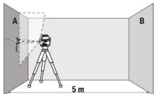
-Hacouete ro nacepot BO 6n3nHa ha sIOT A n octabete ro MEPHNOYpeJa ce HnBEnHp.Obenkete ja CpeHNHaTa Ha ToyKaTa, KaDe Iacepcknte nnHnCe BkpcTyBaat Ha sIOT (Touka I).
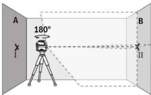
-CbpTeToMepHnOtype3a180°,octabete ro da ce HnBEnnpa nO3HaueTe ja Toyka Ta HbKpctyBahe Ha NacepcknteHHnHa cnpoTHBnT snB (touka II).
-IOCTaBete ro MEPHnOT ypeI -6e3 da ro BpTHe -BO 6n3Ha Ha SuDcT B, BKnyTe ro n octaBeTe ro da ce HnBeInpa.
-IOCTaBETo MepHnOT ypeI NO BHCnHa (co NOMOu HA CTaTINBOT INN EBEHTyaJHO CO NODnOrata), Taka ITO TOKkAHa BA KPCtYBaHe Ha Naacepckte JINHH ToHoo Ke ja NorOAn IpTeXoJHO O3NaueHema ToKa II Ha SInOT B.

-Cbptete ro MePHNOT ype3a 180°,6e3 da ja npomehnte BnCHHATA.Hacouete ro Ha sNDOT A,Taka Ito BePTHKaJIHaTla NacepCKa LHHJa PPOAra Hn3BeKe O3haueHATA TokaI.OCTabete ro MePHNOT ype Da ce HnBeHnpaIO3haueTe ja TOnkata Ha BkPctyBaBe Ha NacepckNTe LHHN Ha sNDOT A (To4Ka III).
PaJIHKaTa dHa DBeTe O3HaueHn ToUKN I I IHI Ha SIOI A ro DaBa faKTNUKOTo OTCaNYBaHBe OD BNCINHaTa Ha MEPHNOTypeI.
HaMepHaIHHJaOg2×5m=10MaKCHMaHHTO
IO3BOLEHOOTcTanyBaHe H3HecyBa:
10mx±0,3mm/m=±3mm.Pa3nKaTa dMerTyTOOKTe I
IIIcMee da H3Hecyba HajMHORY 3mm.
IpoBepKa Ha ToUHocTa Ha HHBenHpBe Ha XOpH3OHTaHaTAAHHJa
3a npoBepka, noTpe6Ha Bn e cno6oHa nOBpuHHa oD OKony 5× 5m
-MoHTnpajTe ro MEPHnOT ypeD BO cpeDHa MeIy sNDOBITE A N B HA cTaTNB IIN NOCTaBeTe ro Ha CBpCTA, paMHa NoIInora. H36peTe ro xOpN3OHTaIHnOT IINHcKn peKHM CO aBTOMaTHka 3a HNBEnPaHe IHNBeHnPajTe ro MEPHnOT ypeD.
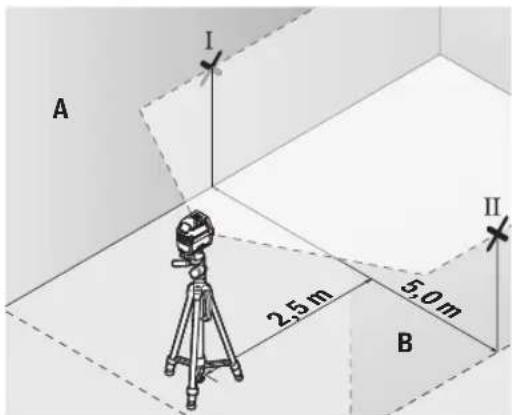
Ha 2,5 m pactojaHne oM MePHNOT ypeD,Ha Dbata snda O3haueTe ja cpeHnHa ta Ha nacepckata HnHnJa (Touka I Ha SIOOT A N TOUkA II HA SIOOT B).
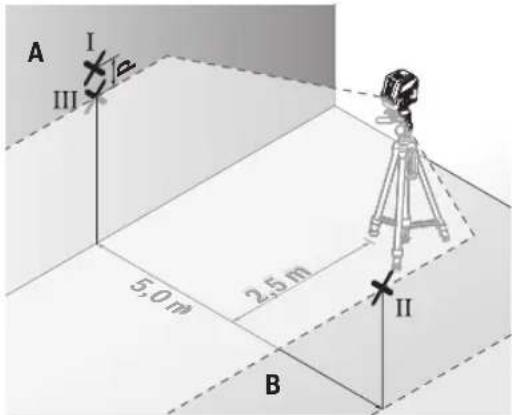
-Notabete ro MEPHnotype, CBPTen 3a 180^ Ha5 m pactojaHne n octabete ro da ce HnBelenpa.
-Noctabete ro MEPHNOtype NO BHCnHa (co nOMoH h CTaTMBOT mN EBEHTyaHNO CO NODnOrata), Taka ITO cpeMHATA Ha NaacepCKnte LHHM TOUHO Ke ja NorOg INPepxOJHO O3HaueHATA ToKa II Ha SInDT B.
Ha sIodOT A obenexete ja cpeHnata Ha nacepckata nnHja kako tOka III (BepTKaIIHO HADnnnoToukata I).
Pa3nKata dHaDbete 03haeHToUckI I I IHa sIodA To DaBa 4aKTNUKOTO OTCaNYBaBe Ha MepHNOt ypeD oD XOpN3OHTaIata.
HaMephaIHHnjaOg 2× 5m = 10m ro daBaMaKcMaHHTo D03BOnHeO OCTanyBaHe:
10m×±0,3mm/m=±3mm.Pa3nKata d Mefy Toukntel I IcMee da n3HecyBa HajMHOry 3 mm.
IpoBepka Ha ToUHocTa Ha HnBEnHpabeTo Ha BeptHKaHATA nnHna
3a KOHTPOna nOtpeBEN Bn e OTOBpO OD BpaTaT, Kae (Ha CBpCTa NODORA) HA cekoja CTpaH a OD BpaTaT hMa MecTo OD Hajmanky 2,5 m.
-Notabete ro MePHNOtypeHa 2,5 m pactoJaHne od OTBOPOT Ha BpaTata Ha cBpCTa, pAMHa NODIora (He ha CTaHB).N36peTe ro BEPTKAnIHNOt IHHNCn peXIM CO ABTomAtNKATA 3a HNBEnPaHbe. HAcOte ja Iacepckata IHHJa Ha OTBOPOT OD BpaTata N OCTabete ro MePHNOtypeDa HNBEnPa.
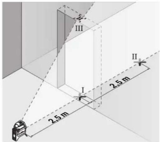
O3haeTe ja cpeHnHa Ta HBeptkAnHata nacepcka nnHjra HnooT od OTbOpot Ha BpaTa (Toka I), Ha 5 m pactoJAHne Ondpyrata CtpaHa HA OTbOpot OD Bpata (Toka II), KaKo H RaopHnot paH bPaTa oD OTbOpot (Toka III).
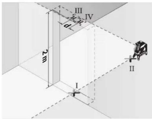
-CbpTeTe ro MEPHNOt ypeI 3a 180° nocTabeTe ro Ha Dpyrata CTpHa HA OTBOPOT HA BpaTATA dIpeKTHO 3aD Toukata II. Octabete ro MEPHNOt ypeI da CE HnBeNIPA u HacoueTe ja BEptTKaIHaTa IacePcKa IInHJa Taka WTo Hej3HNAta CpeINHa Ke NOMHyBa TOHOr HnTOckte I nII.
-Obenexete ja cpeHnata Ha Iacepckata IIHHja Ha roPHnoT pa6 Ha OTBOPoT Ha Bpatata KaKo ToKa IV.
Pa3nKaTa dHaDbete O3haeHn TouKn III IV ro daBa KaTnKToO OTcAnyBaHe Ha MepHnOT ypeoD BeTpNkAJIHnTe IINHN.
-Измерета ja BHCnHaTa Ha OTBOPOT OДВpaTATA. Мakсимално ДОЗВоLEHo OTСТANYBaHBe roпесmetуВate HA cneHnOT haunH:
DBoJHa BnCnHa Ha OTBOpT Ha BpTaTAt × 0,3mm / m PnMep: PnH BcNHa Ha OTBOpT Ha BpTaTAt O2m
MAKCHMaJIHOTO OTCTanyBaHe CMeE Da H3HeCyBa
2× 2m× ± 0,3mm / m = ± 1,2mm .TouKHe III IV cMeat da leXaHajMHory 1,2 mm eHa oD pyra.
PpOBePkHa ToUHocTa Ha IacepcknOt Chon
3a npOBepkata notpe6ha Bn e cno6oHa MePha HnHna Ha CBpcta noIora co pactojaHne oN OKony 5 m nOmeFy nOto H nlafoHOT.
-MoHTnpajTe ro MEPHnOT ypeHa potaunOHnO TpJkau (14) nIOCTabeTe ro Ha noDTo. N3bepeTe ro TOUKeCTnOT pEXHM OCTabEtro MEPHnOT ypeJa ce HNBenpa.
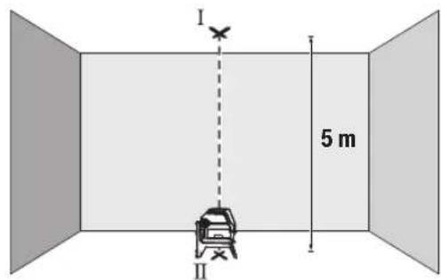
- O3haueTe ja cpeHnHaTa Ha rohpHa Ta nacepcka Touka Ha nlafoHOT (Touka I).OcbEn Toa, oBeIeKe Ja cpeHnHaTa Ha donHa Ta nacepcka Touka Ha noDt (Touka II).
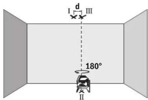
- Cbptete ro MEPHnOt ype3a 180°. IOnsIOnHOnpajte ro Ha Toj HauHH, StTo cpeIHATA Ha DonHaT aacepcka TocKa Ke lexHa BeKe oBeIeXaHATA TOka II. OctabeTe ro MEPHnOt ypeI da CE HNBEnpa. OBeIeXeTe ja cpeIHata Ha rOpHATA Nacepcka TocKa (TOcKa III).
Pa3nKaTa dHaDbTe 03HaueHn Tock H III Ha nnafohot ro daBa KaTNUKOT OCTanyBaHe Ha MepHnot ypeo od BepTHKaJIHNTe nnHH.
MaKcHMaJIHOToIO3B0NEHOOTCTanyBaHe rIpeCMetyBaTe Ha CNeHNOT HauHH:
He ro notonybajTe MEPHnot ypei BO BODa nn npyn TeuHOCTN.
H36pnueTe rHeuCTOTnTE CO BnaXHa MeKa Kpna. He KopncTeTe CpeDCTBa 3a YnCTeHe Hn PaTbOpn.
PeIOBHO UHCTETI HNOBPIHHHTE OKONY I3ne3HNOT OTBOP HA Iacepot IN PnTOA BHIMAbajTe HA BnAkhHeHaTa.
CepBncha cnjx6a n cobet npn kOpncTehe
CepBnchata Cnyk6a Ke OndroBOpn Ha BaWnte npaaHaBo BbPcKa co nonpaBkata N oDpKyBaHbeto Ha BaWnOT npOn3BQd KaKo H pe3epBNHTe DeNoBN. O3HaKn 3a EKcnno3na HnHΦopMaun 3a pe3epBNHTe DeNoBN HCTO Taka Ke Hajdete Ha: www.bosch-pt.com
TMMOT3a COBetyBaBe npn KopncTeHe Ha Bosch Ke BN NOMORHe DOKOLKY HMaTe npaHaHa 3a HaHInTe npOn3BOOn H ONpema.
3a CHTe npaaHbHa HapaKHa pe3epBHN Denobn,Be MOIIME HabeTe Ro 10-ncpHneHOT 6poj OcneuNkauHOHATA NIOUKA Ha npoIN3BOJOT.
Cebepha MaKeDoHja
Д.Д.Енковский
CabaKobayek47H,6poj3
1000 Ckonje
E-nouta: dimce.dimcev@servis-bosch.mk
HHTrepHET: www.servis-bosch.mk
Ten./paKc:02/2467610
Mo6:070595888
D.I.T.Y "POJKA"
JaHnIyKpOBcKn 66;T.IA BtOKOMaHaJIOKaI 69
1000 Ckonje
E-nowa: servisrojka@yahoo.com
Ten: +38923174-303
Mo6: +389 70 388-520, -530
DOnonHnTeHH aDpeCN Ha cepBHCN MoKe Da Hajdete noi:
www.bosch-pt.com/serviceaddresses
OtctpaHyBaBe
MepnTe ypeiOnpemata n ambaanKe Tpe6a da ce OTCTpaHaT Ha ekONOOWKn PnpdaTINb HauH.
He n pnpajTe MepHnTe ypeu H 6aTePnHTe BO DOMaHHaTa KaHaTa 3a rHy6pe!
210|Srpski
Cama 3a 3emjnte oEY:
CnopeEbPONcKaTa DnpeKTHBa 2012/19/EU 3a cTapn
eNEKTPNCHN H eNEKTPOHCKn ypeDN HNBHata ynoTpE6a BO
HaUNHOHNOHOTo 3aKHOHObAcbTO, MepHNTe ypeDN ITO CE BOH
yNoTpe6a N DeFeKTHNTE HN NCKOPNCteHNTE 6aTePN
CnopeDnpeKTHBaTA 2006/66/EC Mopa OndeJHo da ce
co6epa T da ce peukKnnpaaT 3a NOBTOHa ynoTpE6a.
Iokonyce oTcpaHyBaat HenpaBnHo, eNekTpHnHaTa n eNekTPOHcKaTa ONpeMa MOKe Da HMaat WTeTH BnJaHjaBp3 XHBOTHaTa CpeHnHa 3DpaBjTeHa NfReTo NopaMn MoXHOTO PNCycTBo Ha OAnCH MaTePHN.
Srpski
www.bosch-pt.com/serviceaddresses
Uklanjanje dubreta
Merni alati, pribor i ambala za treba da se ukljuce u reciklazu koja odgovara zastiti covekove okoline.
Merne alate i baterije nemojte bacati u kuci nit opad!
Samo za EU-zemlje:
Prema evropskoj direktivi 2012/19/EU o starim elektricnim i elektronskim uredajima i njenoj primeni u nacionalnom pravu, merni alati koji se vishe ne mogu koristiti, a prema evropskoj direktivi 2006/66/EC akumulatori/baterije koje su u kvar ili strošene moraju se odvojeno sakupljati i uklujciu reciklažu koja ispunjava ekoloske uslove.
Ukoliko se elektronski i elektrichi n i uredaji otklone u otpad na neispravan nacin, moguce opasne materije mogu da imaju stetno dejstvo na zivotnu sredinu i zdravlje ljudi.
Slovenscina
Varnostna opozorila

Preberite in upostevajte vsa navodila, da zagotovite varno in zanesljivo uporabo merilne naprave. Ce merilne naprave ne uporabljate v skladu s prilozenimi navodili,
lahko pride do poskodb zašcitne opreme, vgrajene v merilni napravi. Opozorilnih nalepk na merilni napravi nikoli ne zakrivajte. T A NAVODILA VARNO SHRANITE IN JIH PRIOZITE MERILNI NAPRAVI V PRIMERU PREDAJE.
www.bosch-pt.com/serviceaddresses
Odlaganje
Merilne naprave, pribor in embalazo oddajte v okolju prijazno recikliranje.
Merilnih naprav in baterij ne smete odvreci med gospodinjske opadke!
www.bosch-pt.com/serviceaddresses
Zbrinjavanje
Mjerne alate, pribor i ambala ztreba dovesti na ekoloski prihvataljivo recikliranje.
Mjerne alate i baterije ne bacajte u kučni opdat!
Samo za zemlje EU:
U skladu s europskom Direktivom 2012/19/EU o elektricnim i elektronickim starim uredajima i njihovom provedbom u nacionalno pravo neupotrebljivi mjerni alati i u skladu s europskom Direktivom 2006/66/EZ neispravne ili istrošene aku-baterije/baterije moraju se odvojeno sakupljati i davesti na ekoloski prihvatljivo recikliranje.
U slucaju nepravilnog zbrinjavanja elektrichi i elektronicki stari uredaji mogu imati sterne ucinke na okolis i ljudsko zdralvj zbog moguce prisutnosti opasnih tvari.
Eesti
Ohutusnóuded

www.bosch-pt.com/serviceaddresses
Jäätmekäitlus
Darbs ar stativu (papildiederums)
Stativs ir eriece ar regulejamu augstumu, kas paredzeta merinstrumenta stabilai nostiprinasaanai. Izmantojot merinstrumenta 1 / 4'' vitni (10) nostiprintet to uz stativa (23) vitnes vai ari uz parasta fotostativa, ko var iegadaties tirdzniecibas vietas. Lai merinstrumentu nostiprinatu uz tirdzniecibas vietas piejama celtniecibas stativa, izmantojiet 5 / 8'' stipino so vitni (11). Stingri pieskrvejiet merinstrumentu ar stativa stipinajuma skruvi.
Pirms merinstrumenta ieslegsanas aptuveni izlidziniet stativu.
Lazera skatbrilles (papildiederums)
www.bosch-pt.com/serviceaddresses
www.bosch-pt.com/serviceaddresses
Salinimas
www.bosch-pt.com/serviceaddresses
凫
www.bosch-pt.com/serviceaddresses
废弃处理
www.bosch-pt.com/serviceaddresses
廢棄物處理
印在电本道则的动动动动动动动动动动动动动动动动动动动动动动动动动动动动动动动动动动动动动动动动动动动动动动动动动动动动动动动动动动动动动动动动动动动
282|
自通源爱贝国能用是功用
www.bosch-pt.com/serviceaddresses
司
高詠公,默朝社贝王造隆在中忘建程的

请在公用及电电电电电电电电电电电电电电电电电电电电电电电电电电电电电电电电电电电电电电电电电电电电电电电电电电电电电电电电电电电电电电电电电电电电电电电电电电电电电电电电电电电电电电电电电电电电电电电电电电电电
In
nssuwwaaaann

yauuuaaunueauuuuauuauuauuuuuuuuuuuuuuuuuuuuuuuuuuuuuuuuuuuuuuuuuuuuuuuuuuuuuuuuuuuuuuuuuuuuuuuuuuuuuuuuuuuuuuuuuuuuuuuuuuuuuuuuuuuuuuuuuuuuuuuuuuuuuuuuuuuuuuuuuuuuuuuuuuuuuuuuuuuuuuuuuuuuuuuuuuuuuuuuuuuuuuuuuuuuuuuUU
nauuaan anan anan anan anan anan anan anan anan anan anan anan anan anan anan anan anan anan anan anan anan anan anan anan anan anan anan anan anan anan anan anan anan anan anan anan anan anan anan anan anan anan anan
yauuaaunuauauauauauauauauauauauauauauauauauauauauauauauauauauauauauauauauauauauauauauauauauauauauauauauauauauauau
a
nnaaannnnnnnnnnnnnnnnnnnnnnnnnnnnnnnnnnnnnnnnnnnnnnnnnnnnnnnnnnnnnnnnnnnnnnnnnnnnnnnnnnnnnnnnnnnnnnnnnnnnnnnnnnnnnnnnnnnnnnnnnnnnnnnnnnnnnnnnnnnnnnnnnnnnnnnnnnnn
nraanlua
mnnnnaaannnnnnnnnnnnnnnnnnnnnnnn
120 uW W
nannnnnnaaennnnnne nnnnnnnnne nnnnnnne nnnnnnne nnnnnnne nnnnnnne nnnnnnne nnnnnnne nnnnnnne nnnnnnne nnnnnnne nnnnnnne nnnnnnne nnnnnnne nnnnnnne nnnnnnne nnnnnnne nnnnnnne nnnnnnne nnnnnnne nnnnnnne nnnnnnne
nannnnnnnnnnnnnnnnnn
nannnnnnnnnnnnnnnnnnnnnnnnnnnnnnnnnnnnnnnnnnnnnnnnnnnnnnnnnnnnnnnnnnnnnnnnnnnnnnnnnnnnnnnnnnnnnnnnnnnnnnnnnnnnnnnnnnnnnnnnnnnnnnnnnnnnnnnnnnnnnnnnnnnnnnnnnnnnnnnn
WuHua: Huaanmian 45oC
nnaanrnnnnaaannnnnnaaannnnnnaaannnnnnaa
290
mssssss
n
- 100000000000000000000000000000000000000000000000000000000000
- 17777777777777777777777
一n 1
- 1777777777:1777777777777777777777777777777
mnnnnaannnnnnnnnnnnnn
nuuunnuunnuunnuunnuunnuunnu uuuuuuuuuuuuuuuuuuuuuuuuuuuuuuuuuuuuuuuuuuuuuuuuuuuuuuuuuuuuuuuuuuuuuuuuuuuuuuuuuuuuuuuuuuuuuuuuuuuuuuuuuuuuuuuuuuuuuuuuuuuuuuuuuuuuuuuuuuuuuuuuuuuuuuuuuuuuuuuuuuuuuuuuuuuuuuuuuuuuuuuuuuuuuuuuuuuuuuuuuUU
mnuuuaauiuaanai
| aananannannannannannannannannannannannannannannannannannannannannannannannannannannannannannannannannannannannannannannannannannannannannannannannannannannannannannannannannannannannannannannannannannannannannannannannannannannannannannannannannannannannannannannannannannannannannannannannannannannannann annannannannannannannannannannannannannannannannannannannannannannannannannannannannannannannannannannannannannannannannannannannannannannannannannannannannannannannannannannannannannannannannannannannannannannannannannannannannannannannannannannannannannannannannannannannannannannannannannannannannennannannannannannannannannannannannannannannannannannannannannannannannannannannannannannannannannannannannannannannannannannannannannannannannannannannannannannannannannannannannannannannannannannannannannannannannannannannannannannannannannannannannannannannannannannannannannannannannannannannannANNANNANNANNANNANNANNANNANNANNANNANNANNANNANNANNANNANNANNANNANNANNANNANNANNANNANNANNANNANNANNANNANNANNANNANNANNANNANNANNANNANNANNANNANNANNANNANNANNANNANNANNANNANNANNANNANNANNANNANNANNANNANNANNANNANNANNANNANNANNANNANNANNANNANNANNANNANNANNANNANNANNANNANNANNANNANNANNANNANNANNANNANNANNANNANNANNANNANNANNNNANNANNANNANNANNANNANNANNANNANNANNANNANNANNANNANNANNANNANNANNANNANNANNANNANNANNANNANNANNANNANNANNANNANNANNANNANNANNANNANNANNANNANNANNANNANNANNANNANNANNANNANNANNANNANNANNANNANNANNANNANNANNANNANNANNANNANNANNANNANNANNANNANNANNANNANNANNANNANNANNANNANNANNANNANNANNANNANNANNANNANNANNANNANNANNANNANNANNANNANNNNNNNNNNNNNNNNNNNNNNNNNNNNNNNNNNNNNNNNNNNNNNNNNNNNNNNNNNNNNNNNNNNNNNNNNNNNNNNNNNNNNNNNNNNNNNNNNNNNNNNNNNNNNNNNNNNNNNNNNNNNNNNNNNNNNNNNNNNNNNNNNNNNNNNNNNNNNNNNNNNNNNNNNNNNNNNNNNNNNNNNNNNNNNNNNNNNNNNNNNNNNNNNNNNNNNNNNNNNNNNNNNNNNNNNNNNNNNNNNNNNNNNNNNNNNNNNNNNNNNNNNNNNNNNNNNNNNNNNNNNNNNNNNNNNNNNNNNNNNNNNNNNNNNNNNNNNNNNNNNNNNNNNNNNNNNNNNNNNNNNNNNNNNNNNNNNNNNNNNNNNNNNNNNNNNNNNNNNNNNNNNNNNNNNNNNNNNNNN |
n720200000000000000000000000000
nunnnnnnnnnnnnnnnnnnnnnnnnnnnnnnnnnnnnnnnnnnnnnnnnnnnnnnnnnnnnnnnnnnnnnnnnnnnnnnnnnnnnnnnnnnnnnnnnnnnnnnnnnnnnnnnnnnnnnnnnnnnnnnnnnnnnnnnnnnnnnnnnnnnnnnnnnn nn nannn nn nannn nn nannn nn nannn nn nannn nn nannn nn nannn nn nannn nn nannn nn nannn nn nannn nn nannn nn nannn nn nannn nn nannn nn nannn nn nannn nn nannn nn nannn nn nannn nn nannn nn nannn nn nannn nn nannn nn nannn nn nennn nn nannn nn nannn nn nannn nn nannn nn nannn nn nannn nn nannn nn nannn nn nannn nn nannn nn nannn nn nannn nn nannn nn nannn nn nannn nn nannn nn nannn nn nannn nn nannn nn nannn nn nannn nn nannn nn nannn nn nannn nn n ann
一 1
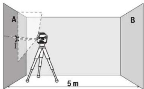
- 1A A a
292 nnu
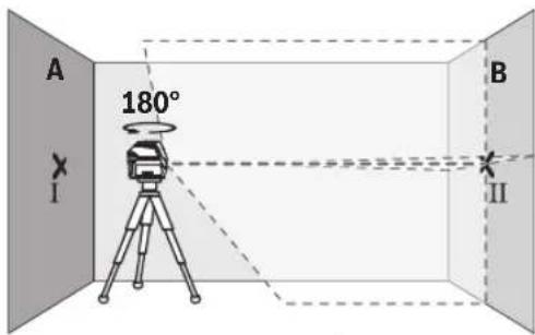
nnuuueeauuuuueaee uuuuueuuuuuuuuuuuuuuuuuuuuuuuuuuuuuuuuuuuuuuuuuuuuuuuuuuuuuuuuuuuuuuuuuuuuuuuuuuuuuuuuuuuuuuuuuuuuuuuuuuuuuuuuuuuuuuuuuuuuuuuuuuuuuuuuuuuuuuuuuuuuuuuuuuuuuuuuuuuuuuuuuuuuuuuuuuuuUU
y: 5.
2×5x.×±0.7/3. =±7 1nun|u:Ⅲnnnnu 7
294
younununnu
H
Inn
Inn 150
Inn 150
Inn 150
Inn 150
Inn 150
Inn 150
Inn 150
Inn 150
Inn 150
Inn 150
Inn 150
Inn 150
Inn 150
Inn 150
Inn 150
in n. 27587555
Inn 027587525
www.bosch-pt.com/serviceaddresses
a
山

ynu!
Bahasa Indonesia
Reflektor (alat pemantulan) (20)出现问题, but it was a good idea to do it.
Arkadia Green Park Tower G-7th floor
JI. Let. Jend. TB. Simatupang Kav.88
Jakarta 12520
Tel.: (021) 3005 5800
Fax: (021) 3005 5801
E-Mail: boschpowertools@id.bosch.com
www.bosch-pt.co.id
www.bosch-pt.com/serviceaddresses
Caramembuang
www.bosch-pt.com/serviceaddresses
Su thai bo
Dung cu do, phu kien va bao bi thai duoc phan loai de tai che theo huong than thieu voi mi truong.
Khong vuit dung cu do va pin cung trong rac thai cua gia dinh!
312
gulglwll osc yjaiy aubll ojeal no aubllicall joo gial abll ojeal agjjall ado glll upo pio uublioguag uuiu.1uguiu 1uoguiu gwlgl wll ooc uabll ojaal aoaig lc lww jg siai dull aubll ojaal agjall
jg aawblallulllbilwg
jUJn.ublallwlll gillg wai all oosgogall uabliol j 1uuiuuiu
1g aaiI 0g
Jg 1
yaaai Jlss
aagbgbll ydlwglsc poaiu .solilblai aalxylgaoagdgasllg .jIg jIyJlsswUwqall .aIyAeI Jjui Uo gauill I. EN 50689 aoIgQIg
jgaaI Jai
wulll ooc gwwj jgwsall jzai siiu w
jUdawgja(1)
(20 _J_J_J (2)
gJgJJ Joo (3)
jjull abai jwllgj j (4)
jjU|baJsaWgjJJ (5)
UJIbUJI 1UJ Ubc (6)
UJIJIJIJIJIJIJIJIJIJIJIJIJIJIJIJIJIJIJIJIJIJIJIJIJIJIJIJIJIJIJIJIJIJIJIJIJIJIJIJIJIJIJIJIJIJIJIJIJIJIJIJIJIJIJIJIJIJIJIJIJIJIJIJIJIJIJIJIJIJIJIJIJIJIJIJIJIJIJIJIJIJIJIJIJIJIJIJIJIJIJIJIJIJIJIJIJIJIJIJIJ
JJJjJ (8)
labygljwulgiao (9)
aog 1/4 gglgJl Jolal jol (10)
a5/8 gJgJU JUJU JU (11)
JuluwuaiJ 12
juiuai
(RM 1)JlgJU JlaJI (14)
aagill aSw (15)
UW (16)
uubliso (17)
(a) aawwI eWw (18)
^a (BM 1) _LJI
(a) jU U gaw aag (20)
(aa2) (21)
(22)
#
Jl

Lgljog lalssllg jg y 1g jolw wll oos Jao 0e plaiw ala .cJbdo
JL L 1 Jg Sd sJgll
JU p a2 .uJall o c y Jaal l Uj
JUaI Oc Ie oogal a Jy dU U
JUaI g .du u Lauu o bai.1.
JUbaI UaI G WJlO JU
alisi aaiy oia
g jn jnsal b uall jilw g i jjessll go 11111111111111111111111111
4j山 aaii
()
aaiJU Lg gSd
aJU 109 JU U JU JU JU JU JU JU JU

ploI I JJJJ 1000000000000000000000000000000000000000000000000000000000000000000000000000
JwI Jg Jg Jg Jg Jg Jg Jg Jg Jg Jg Jg Jg Jg Jg Jg Jg Jg Jg Jg Jg Jg Jg Jg Jg Jg Jg Jg Jg Jg Jg Jg Jg Jg Jg Jg Jg
.1JlssuI JyJUJI Ioo 1abIg, aJIO
jllg l jal gai j 1000000000000000000000000000000000000000000000000000000000000000
jog oSolalitibgulabagulss
Aa
0sol wull osc lc bdool ooc a
Jkuu wulol oxc abii ujao 120
yulu1,1gblauuSulogj
a
/(j)
a 10000000000000000000000000000000000000000000000
Jgj jc lo bai g|Ss yu (5)jjU b a u e gj jg(4)jjU ab
logglaal
a 5x5g aalaaalaaalaa
gipgall jolal B g A jll
aabj sdd. aagmog auiu oJc Ie
oic jilg ayguill ao go aai lla Juswll
.ayguill pogail
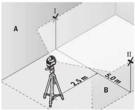
Robert Bosch Morocco SARL
gjoo jol1 gJw,53
J1J120300
+212529314327:
sav.outillage@ma.bosch.com: g S
juiabai jauo jiuu g uji aal yU.(11abail)jolgl aulull
-(laabu)cawuJ
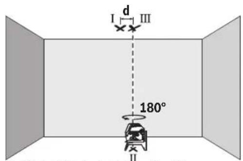
(JJIJJ ajjjLjSawlX
JlJIJIaI aaii 1000
abai jauo aLil s gwi bua oai (gj) JJll jj
-1g20g b 18
ggl jwlaal o s y lgaaglgl aawll
JILsUglaiuua elis
0/00 0,7 × caaaJg aawj81 jw aglwwl c
aJ31 Jg a9luolj gSlo sic:Jlio
ggljgjgjgjg5aawllg
jgl jgai 7=0/00,7x05x2
7 10
JaaI 1sI
-15c 1111
4b g jj山 aboo
abai jS yu. yuill Jn no bag jull aI uall jgo jjllb ojc gjjll
(gIgll) gIgll lJolal abwgl JosJI
Jsauu uuaa aulal gall Jolal 100000000000000000000000000000000000000000000000000000000000000000000000000000
joo jololg (23) jolal
uio Uc uoiUjol.gwUgUdaiI JuaIouuUeUyUgWUgUgUoUuU
. gall lalal b jg qjg jc wqall
g ksw gall glll waiiagw wu
. wgl ooc wosn n
www.bosch-pt.com/serviceaddresses
auijSll ooll no yalill
g g g g g g g g g g g g g g g g g g g g g g g g g g g g g g g g g g g g g g g
5/8"du dw JwJoo (11)
(5) jla(12)
jUJUswComegaμ (13)
(RM1) j_ j_ j (14)
LaiJ J (15)
Juii jgw (16)
wJl
iJgws

jI jai J S 1J J J J J J J J J J J J J J J J J J J J J J J J J J J J J J J J J J J J J
oljom 0o o w jwjl swwc yj jglj l j gagg s jd o kss .JlwnjI Jn nn nnnn nnnn
g jjglj gjglg 0uulgag uulgla uljuljglg auaa odu jnooJkss J.
aui 5yJ S
L
<awjljjjl.

59j 50g jI jJ g Ssi Ijg9 J .sla
.
Laaa ajj
olai jui olaaui
Sicjlgic()
Sicjlgicu
Sj jy Ss s. ssi ool i 100000000000000000000000000000000000000000000000000000000000
sJ 1
a:la6 (5)
jgljUjuaJg
jIwglg jgs ggs 1s dJusssuouo.
CwJ Ss. .Ss .SlaWl (SjI JgS oJslj 5uJLJnUuGg L uJyS paa dWlgai .SgW
山山
g jS L wjL cJLa JlJL Jaii
322|s
^(a) (BT 150) du_Ld (23)
(a) (BT 350) _g ≤slant _w duo (24)
(a) a < 0. 或(25)
ajjduSic (26)
Ujim (17)
(a) Loo o (18)
L uu (s uuaa uu bauu uuuuuiuuiuuiu uuuu uuuu (S uo a
20-25°CJJ(B
o jyj jn jy jy (y) sijg o aie j bi j y gbo u y gao y bai y w os y slao C 336 c9u uuiu uiau uauu uuau uuuu uuuu uuuu uuuu
()
Jai oiaiwl 12 s oiajw jui jai jai wai
:duo o jui gj uoo slgila
1000000000000000000000000000000000000000000
15gacawwduwos
(18)aawdawg
15g2gaw (17)uji 1yJU
LpSoo gbw (sg] U Laleio as jloj
Lalao jI gai Jus
.3j1j j 5x5.8gaaaw uJuiS
15 abai giuly cuaag bawg as suiis pubii (S)gb
Sicg 1g 1g jj j
bng .gui gui i j j j j j j j j
sis 5i sioic j j j abai cua
. (I11 5 aboi)
-III g 0 dω (s)
Sicjlgicu(lalso)jjS Sicj
a u w l s u w jwl jj1 g dlaia .u 10 c u w u s gac jul
:dsdawwdoigS|Jjlo0dai jn
0,7 mm/m aowg g s uu dulg
5JSAaGgCgDolg:Jio
. 山 山 山 山 山 山 山 山 山 山 山 山 山 山 2× 5m× ± 0,7mm / m = ± 7mm jjuiu7jluiuuiu
.duuuljg
Lac slqlaioj
JjJdabjjbawgjl
g dla jui 5uS o slawl jul ba ly jui bai sliq jiaom g jjdl aboi ojl ciu wu .siLgo jui
(Lalso)duuωduJLS
eolaijulaiyLbUcUcOscSydu 1/4" UJlaua aoo.0o ooe yoi jil
(23)dLdwogjj(gj(10)du dwu
Jusil slj. sU Jl jgUw Ugauu uuW oui jIJJU Ugauo uuqw 59
uUjS oJ uJ Jui Soaaw (11) 5/8" .uS Cw dU w
w Cuaai jolil jj JnJg jI uu .suii jipjgl
oijdsjU
(Ggaj aS gaj) (Lalao)
Ugic u Ugi (19) ogac o sjlsasdu Lsogac ggbw (5g) j sijoljjl lio
yoglc.5s yu juii Culg 1s1s1go
du ulgio olaai w luy ogac oij
jIgl aai pabi g cwi wliu ooi jdu
.ais Go Uqwi J sOj1
Laleio wjI Jg juSsil sis
Jy CwU JSS. gJg uubio
.5sLwJuWslUjimSswuS
.ogw aab 3 oJaw ,jUylo jlaaIaw
1994834571 U
9821+42039000:Jol
:duoljJgloa jLw wJ
www.bosch-pt.com/serviceaddresses
olius jssj0sjl
dyLgSsiagw g lalsoj jil jj
g jIa oJ jU wuJ bua bao bu uuLio gjjb
.
JalI Jl (SjI g (SjI jil sI (SjI jJI
!ujiuljui juiuui


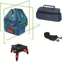


- Deutsch
- Sicherheitshinweise
- Entsorgung
- Product Description and Specifications
- Intended Use
- Product Features
- Technical Data
- Assembly
- Inserting/Changing the batteries
- Working with the RM 1 rotating mount (see figures A1-A3)
- Operation
- Starting Operation
- Switching On/Off
- Automatic Shut-Off
- Temporarily Deactivating Automatic Shut-Off
- Setting the Operating Mode
- 20|English
- Working with Automatic Levelling
- Working with the pendulum lock
- Automatic Levelling
- Working with Automatic Levelling (see figures B1-E1)
- Working with a pendulum lock (see figure F1)
- Accuracy Check of the Measuring Tool
- Influences on Accuracy
- Checking the Height Accuracy of the Horizontal Line
- | English
- Checking the Level Accuracy of the Horizontal Line
- Checking the Level Accuracy of the Vertical Line
- Checking Plumb Accuracy
- Working Advice
- Working with the Tripod (Accessory)
- Securing with the universal holder (accessory) (see figure G)
- Working with the Laser Target Plate (see figure G)
- Laser Goggles (Accessory)
- | Français
- Example Applications (see figures B2-F2, G and H)
- Maintenance and Service
- Maintenance and Cleaning
- After-Sales Service and Application Service
- pare parts at: www.bosch-pt.com
- Malaysia
- Great Britain
- You can find further service addresses at:
- Disposal
- Only for EU countries:
- Only for United Kingdom:
- Français
- France
- Eliminación
- Eliminação
- Smaltimento
- Afvalverwijdering
- Du finder adresser til andre varksteder pa:
- Bortskaffelse
- Du hittar fler kontaktuppgifter till service har:
- Avfallshantering
- Endast for EU-lander:
- Kassering
- Havitys
- Anoupon
- Movi yia xwpec tnc EE:
- Türkce
- Güvenlik talimati
- Tasfiye
- Utylizacja odpadów
- Bodovy a carovy laser GCL 2-15 GCL 2-15 G
- Likvidace
- Bodovy a liniovy laser GCL 2-15 GCL 2-15 G
- Likvidácia
- Hulladékkezelés
- Touecho-nHeHHb naep GCL 2-15 GCL 2-15 G
- Pa6ota c NOBOPOTbIM KpeHHeHEm RM 1 (cm.pnc.A1-A3)
- Pa6ota c nHcTpymeHTOM
- BkIIOUeHHe HNCTpyMeHa
- BkJIOueHHe/BbIKIOueHHe
- ABTomathueckoeOTKIOUOeHne
- BpeMeHHa DeakTHBaun ABToMaTHueCKoTO OTKIOUeHHa
- KoHTpOJIb TOnHOCTH N3MePHTeIbHOrO HHCTpyMenteHa
- ΦaKTopbI, BnHIOUOHe Ha ToUHOCTb
- Bosch.
- IpoBepKa TOUHOCTn ROpH3OHTaJIbHOJ INHHN NO BbICOTE
- IpoBepKa TOUHOCTH HMBENHPoBaHHaTOPN3OHTaNbHOJINHH
- PpOBepKa TOpHocTH HNBENHPoBaHHBepTKaJIbHOH NHHH
- PpOBepKa TOnHOCTN OTBeCa
- Yka3aHnno npImMeHHNO
- Pa6oTa co wTaTHBOM (PnHaDneXHOCtB)
- ΦHKcaunC NOMOuBHO yHNBepcAaBHO rKpeNHeHH (PnHnAdneXHoCTb) (cm. pnc. G)
- Pa60TbC Bn3nPHoM MapKoI (cm.Pnc.G)
- OuKnIpa60bIcna3epHbIM HhCTpyMeHTOM (PnHaadNexKHOCTb)
- 156|YkpaiHcbka
- Texo6cnyxHbHaHe n cepBnC
- Texo6cnyxmbahme n ounctka
- CepBnKoHcyNbTHpOBAHne no BOpocam npMeHeHHA
- www.bosch-pt.com
- DnpernoHa:Pocnna,Benapycb,Ka3axctan,Ykpanha
- Poccn
- DOnonHnTeNbHeIe apeca cepBnChbIX cHTPOB Bbl NaHdTeNo CcblKe:
- Yttnn3aun
- TolboKoDnIaCTpaH-HeHOB EC:
- YkpaIHcbka
- Bka3iBkn 3Texhikn 6e3nekn
- ToukoBo-niiHHn na3ep GCL 2-15 GCL 2-15 G
- MOHTAX
- BctablenHH/3amina6atapeiok
- PobTH 3 NOBOPOTHM KpINJIeHHrM RM1 (INB.MaI.A1-A3)
- Po6ota
- Nouatok po60Tu
- BMnKaHHBmKHaHH
- 160|YkpaiHcbka
- ABTOMATUHE BHMKHAAHRA
- THMycOBA DeakTBaui aBToMaTHHOro BHMKaHHA
- BctaHOBHeHHpeKmMy po60TH
- Ipebipka Touhocti Hibenobanra Ropn3oHTabHOi nii
- IpeBipka ToHocTi Bncka
- Bka3iBKn odo p6oToN
- Pobota 3i wtaTbOM (npnlaa)
- Φikcaia 3a donomoro yhibepcnaBHOKpInnHn (npnaad) (DVB. Man. G)
- PobTH 3 Bi3npHO MapKOIO (Hb.MaI.G)
- Ytunizaia
- Пишдя Крайн EC:
- Ka3ak
- Eypa3nna 3koHOMnKaIbIK odaftbHa (Kehen odaftbHa) Mywe MemlekeTepayMaftbHa
- KoIJaHbIJaDbI
- Ohimdi nai danahny MEP3iMi
- Kb3mETKeHemecnaiDnAhyBHBkKatenikTepi Me icTeH bFy ce6entepinT3imi
- 161Ka3aK
- Tacbimanday
- Kayinci3ik HycKaynapbI
- MaTHnKTI 6yTaTTay teririmeH xymbic ictey (F1 cypetih kapaHbi3)
- Oneyky KypanbHbH, dAnirin TeKcepy
- Дэлдik acepepi
- KoIeHeH cb3bIKtBn 6nIKtik dAndiirin Tekcepy
- Ja3ep KOpy Ke3inDipiri (kepek-kaPak)
- Kymbc Mbicanapbl (MbHa cypETepi KapaHb13: B2-F2, G XeHe H)
- TexHnKaIbIK KyTIM XHe KbI3MeT
- KbI3MeT KOpCteTy XHe ra3anay
- TyTbHyBbIfa KbI3MeT KOpCeTy XHe naIdaNaHy KeHecTepi
- Ka3aKcTah
- KbI3Met Kepcety optaIbIKtapbIHbH 6acka da MeKeHxaJInapbIH MbHa JKepeH KapaHbI3:
- Kedere kapaTy
- Tek kana EO endepi yuin:
- Jshonjmo
- Jusommbjou 06n3nu anonnog
- ydsmsds6dansu gnsusmno (nb.ugn.F1)
- usman bomubymbuoyuol aagmddgds
- bgyuogg amjgon gmo
- bobyuouo 3mno86ymo bssjoo
- aagmabunyymnabqamgbs
- yGnno8b0s
- Româna
- Instruţiuni de siguranta
- Eliminarea
- ToykOB mIHeen naep GCL 2-15 GCL 2-15 G
- MOnTupahe
- H3non3BaHe/cmHa Ha 6aTepuNTe
- IeHocn C BbpTaaTa Ce cToKa RM 1 (Bk. fnr. A1-A3)
- Pa6ota
- Iyckahe B eKcnnoataua
- BknIOuBaHe n H3KIOUoBaHe
- ABTomaTHH0 H3K1HO4BaHe
- BpeMeHNO DeakTHBnpaHe Ha aBTOMaTHUHOTO n3KIIIOuBaHe
- H36op ha pexkma ha pa60Ta
- ABTomathno HnBennpahe
- Pa6ota cABTOMATHNO HHBENPAAE (BXK.ΦHR.B1-E1)
- DeHHocTc maxaHNo apetnpae (Bx. qHr.F1)
- PpOBepKa 3a TouHcT Ha H3MePbTeHNnYpe
- ΦaKTOpH, BnIReuHa ToUHocTtA
- PpOBepKa HA ToUHOCCTTA H BNCouHHATA Ha XOpH3OHTaHATA JINHH
- PpOBepKa Ha ToUHocTtHa HnBEnHpAne Ha XOpH3OHTaJIHATA JHHN
- PpOBepKa Ha ToHOCCTTa Ha HNBenHpAe BbB BepTKaIHO HanpaBHeHne
- PpOBepka Ha ToHocTHa OTBeca
- Yka3aHn 3a pa60Ta
- Pa6oTa cbc cTaTHB (pHnHaIeXHoCT)
- MOnTHnpaHc yHHBepcaHATA cTouKa (npHHaJIeXHOCT) (BHXTeΦHr.G)
- Pa6ota c na3ephata MepuTeHa nnoa (Bx. fHr. G)
- OuHnHa6nDaaHe Ha na3epHnIbU (npHnAdnEeKHOCT)
- Pa6OTHn npHmepn (Bx. qnr.B2-F2,GnH)
- PoaBpKaHe n cepBn3
- IopdbpxaHe n nouHCTBaHe
- KInHeTcKa CnyX6a H KOHcyIaunr OTHoCHO yNoTe6ata
- BbIraPna
- DpyrH cepBn3Hn apecn uie otKpneTe Ha:
- BpaKyBaHe
- Cama 3a cTpaHH ot EC:
- MaKeDoHcKn
- Бe36eДнocHn HanomeHH
- Onnc Ha npoH3B0DoT nepopmaHCNTe
- YnoTpe6a co cooDbetHa HameHa
- Hnyctpaunja ha KOMnOHeHTN
- Texnukn noaToun
- Ynortpe6a
- CtabaBeBoynotpe6a
- BknyBaBe/HcknyBaBe
- AbTomatkaHaHcknyuYaBahe
- JaekTNBnpaHe Ha aBTOMaTHKaTa 3a NcknyuByBaBe
- NoecyBaHe Ha pexHmOT Ha pa60Ta
- KoHTpOHa ToUHOCTa Ha MepHnOtype
- BnjuhaJaHaToHocTa
- Поберка Ha ToUHocta Ha BnCHHaT ha XOpN3OHTaHHaTaJIHHJa
- IpoBepKa Ha ToUHocTa Ha HHBenHpBe Ha XOpH3OHTaHaTAAHHJa
- IpoBepka Ha ToUHocTa Ha HnBEnHpabeTo Ha BeptHKaHATA nnHna
- PpOBePkHa ToUHocTa Ha IacepcknOt Chon
- CepBncha cnjx6a n cobet npn kOpncTehe
- Cebepha MaKeDoHja
- DOnonHnTeHH aDpeCN Ha cepBHCN MoKe Da Hajdete noi:
- OtctpaHyBaBe
- 210|Srpski
- Cama 3a 3emjnte oEY:
- Srpski
- Uklanjanje dubreta
- Samo za EU-zemlje:
- Slovenscina
- Varnostna opozorila
- Odlaganje
- Zbrinjavanje
- Samo za zemlje EU:
- Eesti
- Ohutusnóuded
- Jäätmekäitlus
- Darbs ar stativu (papildiederums)
- Lazera skatbrilles (papildiederums)
- Salinimas
- 凫
- 废弃处理
- 廢棄物處理
- 司
- In
- nssuwwaaaann
- nauuaan anan anan anan anan anan anan anan anan anan anan anan anan anan anan anan anan anan anan anan anan anan anan anan anan anan anan anan anan anan anan anan anan anan anan anan anan anan anan anan anan anan anan
- nraanlua
- nannnnnnnnnnnnnnnnnn
- mssssss
- n720200000000000000000000000000
- nnu
- 294
- younununnu
- Bahasa Indonesia
- Caramembuang
- Su thai bo
- 1g aaiI 0g
- yaaai Jlss
- jgaaI Jai
- #
- Jl
- .1JlssuI JyJUJI Ioo 1abIg, aJIO
- jog oSolalitibgulabagulss
- Aa
- logglaal
- JaaI 1sI
- (gIgll) gIgll lJolal abwgl JosJI
- wJl
- iJgws
- Lac slqlaioj
- (Lalso)duuωduJLS
Brand : BOSCH
Model : GLL 215 Professional
Category : Laser pointer