GOL 32 G Professional - Multimeter BOSCH - Free user manual and instructions
Find the device manual for free GOL 32 G Professional BOSCH in PDF.
| Product Type | Optical Level |
| Brand | Bosch |
| Model | GOL 32 G Professional |
| Range | 120 m |
| Height Accuracy (Single Measurement) | 1 mm/30 m |
| Standard Deviation for 1 km Double Leveling | 1.0 mm |
| Magnification | 32x |
| Objective Lens Diameter | 36 mm |
| Field of View | 1°30' |
| Minimum Measuring Distance | 0.3 m |
| Graduation of Horizontal Circle | 1 gon |
| Compensator Leveling Range | ±15' |
| Magnetic Damping | Yes |
| Circular Bubble Accuracy | 8'/2 mm |
| Tripod Connection | 5/8" |
| Weight (per EPTA 01:2014) | 1.5 kg |
| Protection Class | IP54 |
| Power Supply | None (optical mechanical instrument) |
| Main Functions | Determination and checking of horizontal level, measurement of heights, distances and angles |
| Maintenance | Clean with a soft, damp cloth, store in case, replace silica gel |
| Safety | Read instructions, have repairs carried out only by qualified personnel using original parts |
| Spare Parts and Repairability | Available via Bosch after-sales service; serial number required |
| General Information | Supplied in a case; read instructions before use |
Frequently Asked Questions - GOL 32 G Professional BOSCH
User questions about GOL 32 G Professional BOSCH
0 question about this device. Answer the ones you know or ask your own.
Ask a new question about this device
Download the instructions for your Multimeter in PDF format for free! Find your manual GOL 32 G Professional - BOSCH and take your electronic device back in hand. On this page are published all the documents necessary for the use of your device. GOL 32 G Professional by BOSCH.
USER MANUAL GOL 32 G Professional BOSCH
he CoHDAHANHA HCTDTRKUNA
m04HACHOYFCTD93.0507A
srOriginalinguputstvozara
sIwima raydila
hr Originalge upute 2a rad
et Alagpurane kasutisuhend
Instrukcijasoriginalvalda
It Originalinsrukcia
zh正本使用说明书
zh原始使用说明者
ko山用电
n
24
Id Petunuk-Petunuk unuuk
Pepagunaar Orsinal
MaKeDoHcN. CtpaHua 102
Srpski Strana 107
Slovenscina Stran 111
www.bosch-pt.com/serviceaddresses
Entsorgung
All instructions must be read and observed in order for the measuring tool to function safely. The safeguards integrated into the measuring tool may be compromised if the
measuring tool is not used in accordance with these instructions. Never make warning signs on the measuring tool unrecognisable. SAVE THESE INSTRUCTIONS FOR FUTURE REFERENCE AND INCLUDE THEM WITH THE MEASURING TOOL WHEN TRANSFERRING IT TO A THIRD PARTY.
Have the measuring tool serviced only by a qualified specialist using only original replacement parts. This will ensure that the safety of the measuring tool is maintained.
Product Description and Specifications
Please observe the illustrations at the beginning of this operating manual.
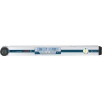
Intended Use
The measuring tool is intended for establishing and checking exactly horizontal height profiles. It is also suitable for measuring heights, distances and angles.
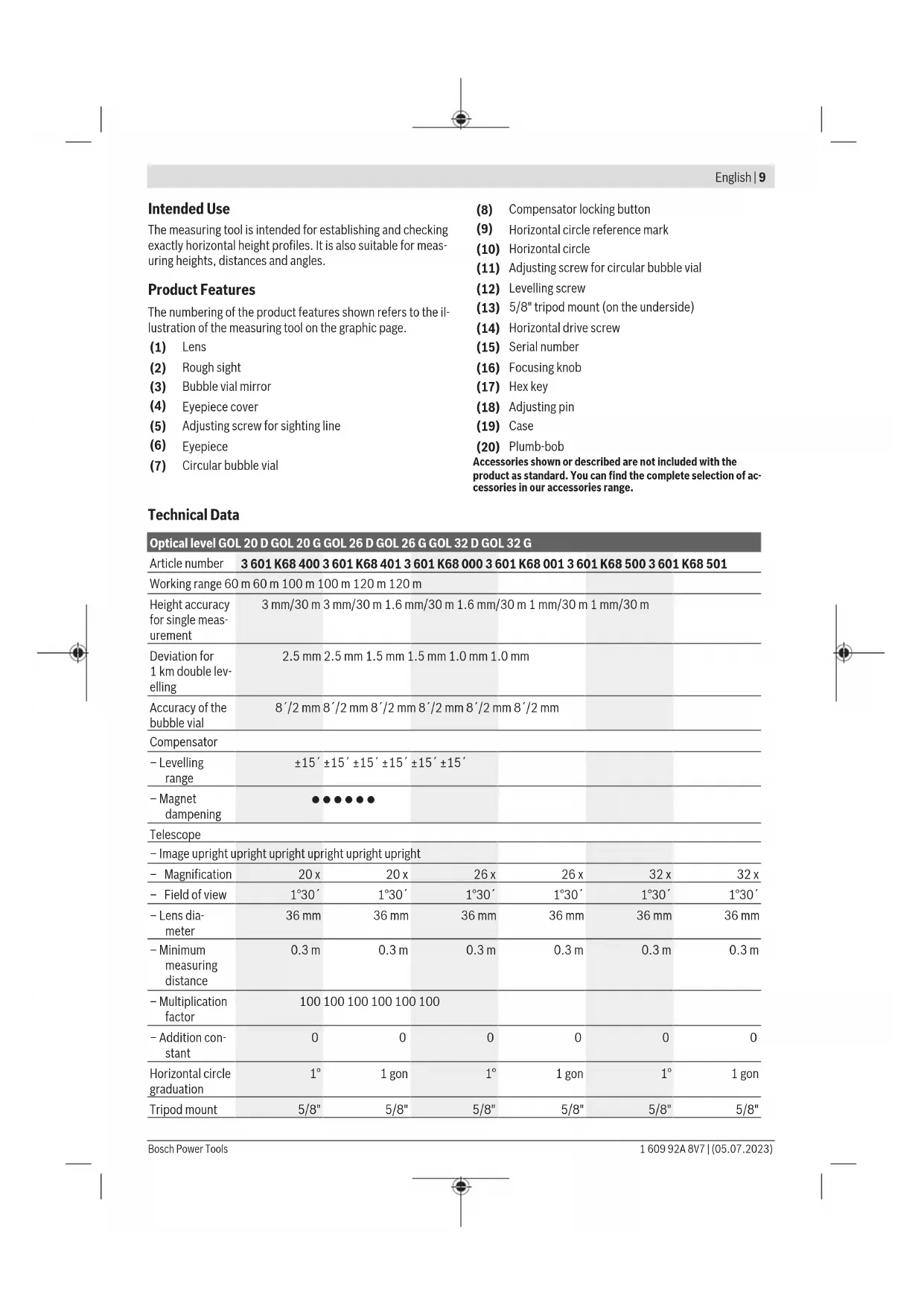
Product Features
The numbering of the product features shown refers to the illustration of the measuring tool on the graphic page.
(1) Lens
(2) Rough sight
(3) Bubble vial mirror
(4) Eyepiece cover
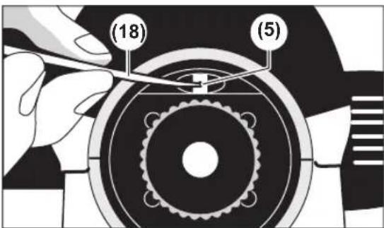
(5) Adjusting screw for sighting line
(6) Eyepiece
(7) Circular bubble vial
(8) Compensator locking button
(9) Horizontal circle reference mark
(10) Horizontal circle
(11) Adjusting screw for circular bubble vial
(12) Levelling screw
(13) 5 / 8'' tripod mount (on the underside)
(14) Horizontal drive screw
(15) Serial number
(16) Focusing knob
(17) Hex key
(18) Adjusting pin
(19) Case
(20) Plumb-bob
Accessories shown or described are not included with the product as standard. You can find the complete selection of accessories in our accessories range.
Technical Data
Optical level GOL 20 D GOL 20 G GOL 26 D GOL 26 G GOL 32 D GOL 32 G
| Article number | 3601 K68 400 3601 K68 401 3601 K68 000 3601 K68 001 3601 K68 500 3601 K68 501 | |||||
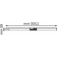
| Working range | 60 m | 100 m | 120 m | 120 m | ||
| Height accuracy for single measurement | 3 mm/30 m | 3 mm/30 m | 1.6 mm/30 m | 1.6 mm/30 m | 1 mm/30 m | 1 mm/30 m |
| Deviation for 1 km double levelling | 2.5 mm | 2.5 mm | 1.5 mm | 1.5 mm | 1.0 mm | 1.0 mm |
| Accuracy of the bubble vial | 8'/2 mm | 8'/2 mm | 8'/2 mm | 8'/2 mm | 8'/2 mm | 8'/2 mm |
| Compensator | ||||||
| - Levelling range | ±15' | ±15' | ±15' | ±15' | ±15' | |
| -Magnet dampening | ●●●●●●●●●●●●●●●●●●●●●●●●●●●●●●●●●●●●●●●●●●●●●●●●●●●●●●●●●●●●●●●●●●●●●●●●●●●●●●●●●●●●●●●●●●●●●●●●●●●● ●●●●●●●●●●●●●●●●●●●●●●●●●●●●●●●●●●●●●●●●●●●●●●●●●●●●●●●●●●●●●●●●●●●●●●●●●●●●●●●●●●●●●●●●●●●●●●●●●●●● | |||||
| Telescope | ||||||
| -Image upright upright upright upright upright upright | ||||||
| -Magnification | 20 x | 20 x | 26 x | 26 x | 32 x | 32 x |
| -Field of view | 1°30' | 1°30' | 1°30' | 1°30' | 1°30' | 1°30' |
| -Lens diameter | 36 mm | 36 mm | 36 mm | 36 mm | 36 mm | 36 mm |
| -Minimum measuring distance | 0.3 m | 0.3 m | 0.3 m | 0.3 m | 0.3 m | 0.3 m |
| -Multiplication factor | 100 | 100 | 100 | 100 | ||
| -Addition constant | 0 | 0 | 0 | 0 | 0 | 0 |
| Horizontal circle graduation | 1° | 1 gon | 1° | 1 gon | 1° | 1 gon |
| Tripod mount | 5/8" | 5/8" | 5/8" | 5/8" | 5/8" | 5/8" |
10 | English
| Optical level GOL 20 D GOL 20 G GOL 26 D GOL 26 G GOL 32 D GOL 32 G | |||||
| Weight accord- ing to EPTA-Pro- ced- ure 01:2014 | 1.5 kg | 1.5 kg | 1.5 kg | 1.5 kg | 1.5 kg |
| Protection rat- ing | IP 54 (dust and splash-proof) | ||||
The serial number (15) on the type plate is used to clearly identify your measuring tool.
Operation
Check the levelling and display accuracy of the measuring tool each time before beginning work and after longer transport of the measuring tool.
Protect the measuring tool from moisture and direct sunlight.
Do not expose the measuring tool to any extreme temperatures or variations in temperature. For example, do not leave it in a car for extended periods of time. In case of large variations in temperature, allow the measuring tool to adjust to the ambient temperature before putting it into operation. The precision of the measuring tool may be compromised if exposed to extreme temperatures or variations in temperature.
- Avoid any impact to or dropping of the measuring tool. Always carry out an accuracy check before continuing work if the measuring tool has been subjected to severe external influences (see "Accuracy Check of the Measuring Tool", page 11).
- Place the measuring tool in the provided case when transporting it over longer distances (e.g. in the car). Ensure that the measuring tool is correctly placed in the case. When placing in the case, the compensator is locked, as the measuring tool may otherwise be damaged by strong movements.
Setting Up/Aligning the Measuring Tool
Mounting on the Tripod
Set up the tripod so that it is stable and secured against tipping over or slipping. Place the measuring tool onto the thread of the tripod via the tripod mount (13) and secure the measuring tool with the locking screw of the tripod. Align the tripod roughly.
Over short distances, the measuring tool can be carried whilst mounted on the tripod. In order to avoid damage to the measuring tool, the tripod must be held vertically during transport and should not e.g. be carried lengthwise over the shoulder.
Aligning the Measuring Tool
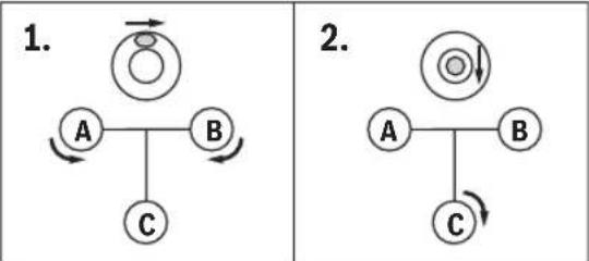
Align the measuring tool using the levelling screws (12) so that the air bubble is positioned in the centre of the circular bubble vial (7).
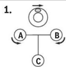
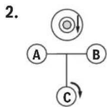
Turn the first two levelling screws A and B to move the air bubble so that it is centred between the two levelling screws. Then turn the third levelling screw C until the air bubble is positioned in the centre of the circular bubble vial.
Any remaining deviation of the measuring tool from the horizontal plane following the balancing of the circular bubble vial is compensated for by the compensator.
While working, check regularly (e.g. by looking through the bubble vial mirror 3) whether the air bubble is still in the centre of the circular bubble vial.
Centring the Measuring Tool over a Ground Point
If necessary, centre the measuring tool over a ground point. To do this, hang the plumb-bob (20) on the locking screw of the tripod. Align the measuring tool over the ground point either by moving the measuring tool on the tripod or by adjusting the tripod.
Focusing the Telescope
Remove the protective cap from the lens (1).
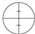
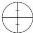
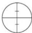
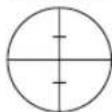
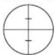
Point the telescope at a bright object or hold a white sheet of paper in front of the lens (1). Turn the eyepiece (6) until the crosshairs appear sharp and deep black.
Point the telescope at the levelling rod, using the rough sight (2) if necessary. Turn the focusing knob (16) until the graduation field of the levelling rod can be seen sharply. Align the crosshairs exactly with the centre of the levelling rod by turning the horizontal drive screw (14).
When the telescope is correctly focused, the crosshairs and the image of the levelling rod must not move against each other when the eye is moved behind the eyepiece.
Measuring Functions
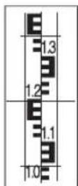
Always set up the levelling rod exactly vertically. Point the aligned and focused measuring tool at the levelling rod so that the crosshairs are on the centre of the levelling rod.
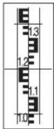
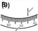
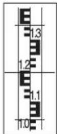
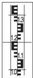
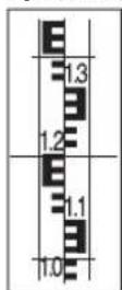
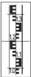
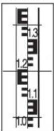
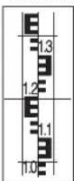
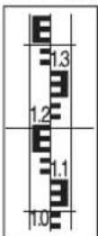
Reading Off the Height

Read off the height on the levelling rod at the centre line of the crosshairs. Height measured in the figure: 1.195m
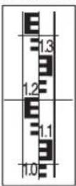
Measuring a Distance
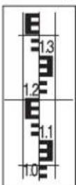
Centre the measuring tool over the point from which the distance is to be measured. Read off the height on the levelling rod at the top and bottom lines of the crosshairs. Multiply the difference between the two heights by 100 to get the distance from the measuring tool to the levelling rod. Distance measured in the figure: (1.347m - 1.042m)× 100 = 30.5m
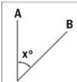
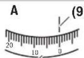
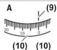
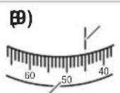
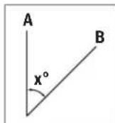
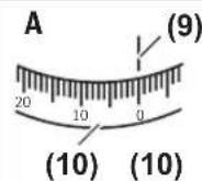
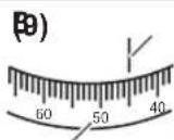
Measuring Angles
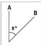
Centre the measuring tool over the point from which the angle is to be measured.
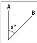
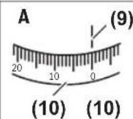
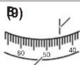
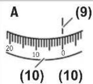
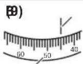
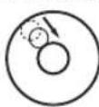
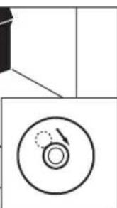
Point the measuring tool at point A. Rotate the horizontal circle (10) with the zero point toward the reference mark (9). Then point the measuring tool at point B. Read off the angle at the reference mark (9).
GOL 20 D/GOL 26 D/GOL 32 D: Angle measured in the ex-ample: 45^
GOL 20 G/GOL 26 G/GOL 32 G: Angle measured in the example: 45 gon.
Accuracy Check of the Measuring Tool
Check the levelling and display accuracy of the measuring tool each time before beginning work and after longer transport of the measuring tool.
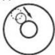
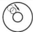
Checking the Circular Bubble Vial
Align the measuring tool using the levelling screws (12) so that the air bubble is positioned in the centre of the circular bubble vial (7).
Rotate the telescope by 180^ . If the air bubble is no longer in the centre of the circular bubble vial (7), the circular bubble vial must be readjusted.
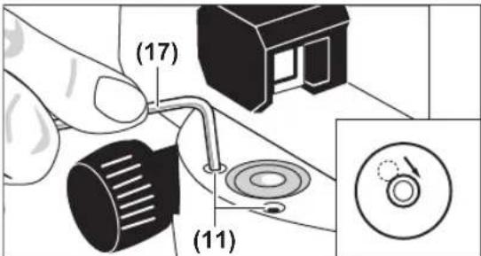
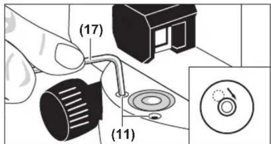
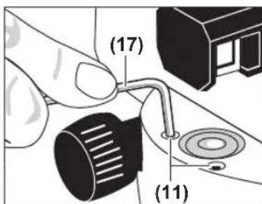
Readjusting the Circular Bubble Vial
Move the air bubble of the circular bubble vial (7) to a position midway between the end position of the check and the centre by turning the levelling screws (12).
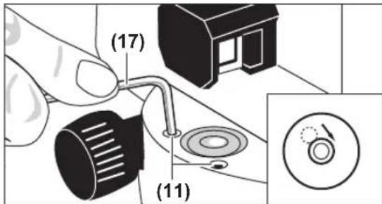
Using the hex key (17), turn the adjusting screws (11) until the air bubble is positioned in the centre of the circular bubble vial.
Check the circular bubble vial by rotating the telescope by 180^ . Repeat the adjustment procedure if necessary or contact Bosch customer service.
Checking the Compensator
After aligning and focusing the measuring tool, measure the height at a reference point. Then press and release the locking button of the compensator (8). Measure the height at the reference point again.
If the two heights do not match exactly, have the measuring tool repaired by Bosch customer service.
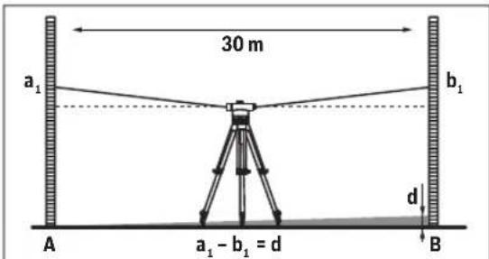
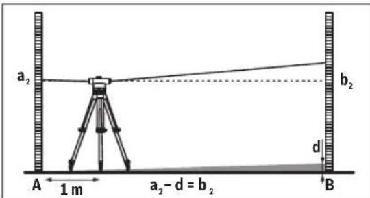
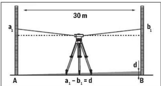
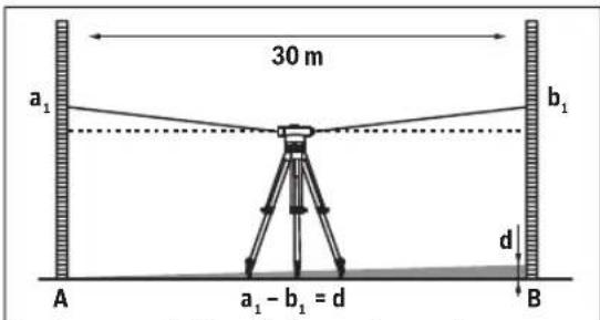
Checking the Crosshairs
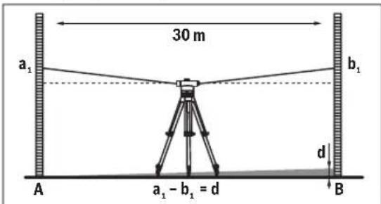
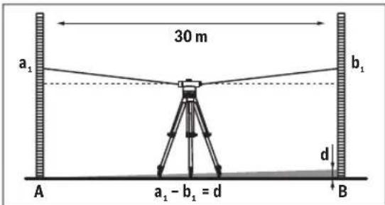
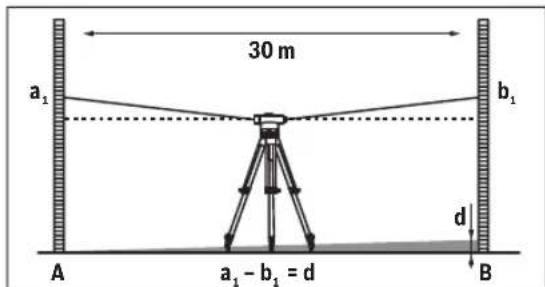
A measuring distance of approx. 30m is required for the check. Set up the measuring tool in the centre and levelling rods A and B at both ends of the measuring distance.
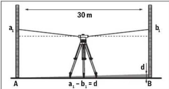
After aligning and focusing the measuring tool, read off the heights at both levelling rods. Calculate the difference d between the height a1 on levelling rod A and the height b1 on levelling rod B .
Example:
a1=1.937m
b=1.689m
a_1 - b_1 = 1.937m - 1.689m = 0.248m = d
12 | English

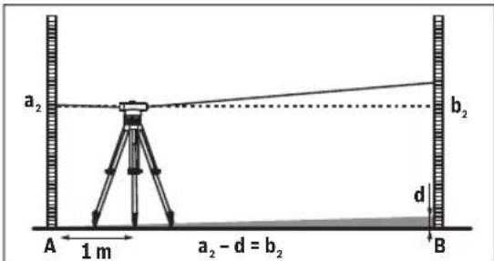
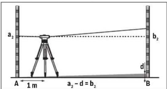
Set up the measuring tool approx. 1 m away from levelling rod A. After aligning and focusing the measuring tool, read off the height a_2 at levelling rod A.
Subtract the previously calculated value d from the measured height a_2 in order to obtain the set value for the height b_2 at levelling rod B.
Measure the height b_2 at levelling rod B. If the measured value deviates by more than 6mm (GOL 20 D/G), 3mm (GOL 26 D/G) or 2mm (GOL 32 D/G) from the calculated set value, the crosshairs must be readjusted.
Example:
a_2 = 1.724m
= 0.248m
a_2 - d = 1.724m - 0.248m = 1.476m
GOL 20 D/G: When measuring, the height b_2 must be 1.476m± 6mm
GOL 26 D/G: When measuring, the height b_2 must be 1.476m± 3mm
GOL 32 D/G: When measuring, the height b_2 must be 1.476m± 2mm
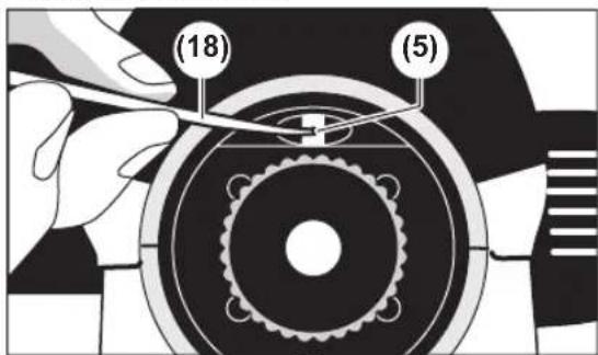
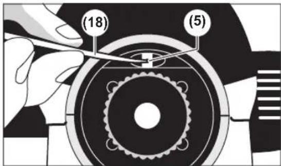
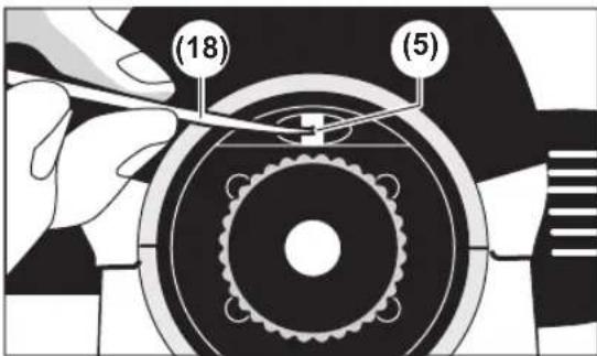
Readjusting the Crosshairs
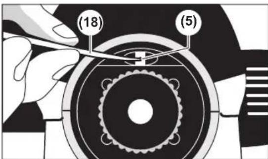
Unscrew the eyepiece cover (4). Using the adjusting pin (18), turn the adjusting screw (5) clockwise or anticlockwise, until the calculated set value for the height b_2 is reached when measuring on levelling rod B. Screw the eyepiece cover (4) back on.
Example:
When measuring b_2 , the value 1.476m must be
Check the crosshairs again. Repeat the adjustment procedure if necessary or contact Bosch customer service.
Maintenance and Service
Maintenance and Cleaning
Store and transport the measuring tool only in the supplied case.
Keep the measuring tool clean at all times.
Never immerse the measuring tool in water or other liquids. Wipe off any dirt using a damp, soft cloth. Do not use any detergents or solvents.
Handle the lenses with particular care. Remove dust only with a soft brush. Do not touch the lenses with your fingers. Before storing, allow the measuring tool and the case to dry completely. In the case, there is a bag containing desiccant, which binds residual moisture. Replace the desiccant bag regularly.
If the measuring tool needs to be repaired, send it off in the case.
After-Sales Service and Application Service
Our after-sales service responds to your questions concerning maintenance and repair of your product as well as spare parts. You can find explosion drawings and information on spare parts at: www.bosch-pt.com
The Bosch product use advice team will be happy to help you with any questions about our products and their accessories.
In all correspondence and spare parts orders, please always include the 10-digit article number given on the nameplate of the product.
Great Britain
Robert Bosch Ltd. (B.S.C.)
P.O.Box 98
Broadwater Park
North Orbital Road
Denham Uxbridge
UB 95HJ
At www.bosch-pt.co.uk you can order spare parts or arrange the collection of a product in need of servicing or repair.
Tel. Service: (0344) 7360109
E-Mail: boschservicecentre@bosch.com
You can find further service addresses at:
www.bosch-pt.com/serviceaddresses
Disposal
Measuring tools, accessories and packaging should be recycled in an environmentally friendly manner.
Only for EU countries:
According to the Directive 2012/19/EU on waste electrical and electronic equipment and its transposition into national law, measuring tools that are no longer usable, and, according to the Directive 2006/66/EC, defective or drained batteries must be collected separately and disposed of in an environmentally correct manner.
If disposed incorrectly, waste electrical and electronic equipment may have harmful effects on the environment and
human health, due to the potential presence of hazardous substances.
Only for United Kingdom:
According to The Waste Electrical and Electronic Equipment Regulations 2013 (SI 2013/3113) (as amended) and the Waste Batteries and Accumulators Regulations 2009 (SI 2009/890) (as amended), products that are no longer usable must be collected separately and disposed of in an environmentally friendly manner.
Français
www.bosch-pt.com/serviceaddresses
www.bosch-pt.com/serviceaddresses
Eliminación
www.bosch-pt.com/serviceaddresses
Smaltimento
Compensator controller
www.bosch-pt.com/serviceaddresses
Afvalverwijdering
Bosch Service Center
Telegrafvej 3
2750 Ballerup
Pá www.bosch-pt.dk kan der online bestilles reservedele el-ler oprettes en reparations ordre.
TIf. Service Center: 44898855
Fax:44898755
E-Mail: vaerktoej@dk.bosch.com
www.bosch-pt.com/serviceaddresses
Bortskaffelse
Bosch Service Center
Telegravej 3
2750 Ballerup
Danmark
Tel.: (08) 7501820 (inom Sverige)
Fax: (011) 187691
Du hittar fler kontaktuppgifter till service har:
www.bosch-pt.com/serviceaddresses
Avfallshantering
Rett stativet grovt opp.
www.bosch-pt.com/serviceaddresses
Kassering
www.bosch-pt.com/serviceaddresses
Hävitys
Eunnpertno naeawkououeepapoyic
H unnpedia eunnpetnnc neatawv anavta otic epwthoeic oac oxetikae Tnv eniakeun kai tn ouvtphonan Tou npoiovtoc aoc kaohc kai yia ta avriatoxa avtaalakntika. xedia uuvapoo loynnc kai nnpopopie cya ta avtaalakntka 0a bpeite eni onk katw and:
www.bosch-pt.com
H oua npaoxic ouuouaw nC Bosch anavta euxapiatwC tic epwnoeic oac yia ta npoiovta mac kal ta eapntmuata touc. Awote oe ole cie epwnoeic kai npayyeiec avtaalaktkow onwaahnoto 10npiio kwdk apiog oupova me tny mvakla tunou tou npoiovtoc.
EAaa
Robert Bosch A.E.
Epexia37
19400Kopwni-Aθηγα
Tnλ:2105701258
ΦaE:2105701283
Email: pt@gr.bosch.com
www.bosch.com
www.bosch-pt.gr
Iepatepw dieuovoc aepic 8a pteor nV nAeKtpovk dieuovon:
www.bosch-pt.com/serviceaddresses
Anoupon
Ta opyava metpnc, ta eapntmuata kai ouakeuaiec npenei va avakukawovtae TPOTO pioK npoc to nepiaA lov.
Movi yia xwpec tnc EE:
www.bosch-pt.com/serviceaddresses
Tasfiye
Robert Bosch Sp. z o.o.
www.bosch-pt.com/serviceaddresses
Utylizacja odpadów
Bosch Service Center PT
K Vapence 1621/16
692 01 Mikulov
Na www.bosch-pt.cz si si muzete objednat opravu Vaseho stroje nebo nahradni dily online.
www.bosch-pt.com/serviceaddresses
Likvidace
www.bosch-pt.com/serviceaddresses
Likvidácia
Vyrobok, prisluensstvo a obal treba dat na recyklaciu setriacu zivotne prostredie.
Len pre krajiny EU:
www.bosch-pt.com/serviceaddresses
Hulladékkezelés
Kpntepnn npedeBbix coCToHHN
- noBpeKdEn KOpNc n3eJIINr
TnHn nepnoHQocTB texHmecKoro 6cbnyxmbaHHN
PekomeHcyTcOHTbHHCTpyMeHrOT Nblnn NoCne KaK-DOHOHCNOB3OBAHN.
Xpahenne
Heo6xOIMO XpaHb BCyXOMecTe
Heo6xoJIMMOxpaHHTbBdAINOTIcTOUHKOBIOBblIeH HbIXTEMNEpApTyNBO3JeCTBnCOJIHeHbIXNyuei
- npn xpaHenn Heo6xOIMO n36eraTb pe3Koro nepenada TeMneparyp
-ecnHhCTpyMeHT NOCTaBnRETCB MmKoCymKe HnPiactIKOBOM KeIe peKoMeHdYETcXpaHHTb HhCTpyMeHT B30J 3aunTHOH yNaKOBke
- noPpO6HbIe Tpe6oBaHN K yCNoBnM XpaHeHHa CMOTpHTe BTOCT 15150-69 (YcNoBne 1)
TpaHcnpToPobKa
KaTeRoPnueckn He DoNyckaetcnaJeHHe N IIObIe MExaHneckn BO3dEChTBHa Ha yNaKOBky npn TpaHcNoptnPOBKe
- npn pa3rpy3ke/norpy3ke He donyckaetcH nCnoIb30BaHne IIO6O BnDa TexNkH, pa6oTaIOeH no npHHuNy 3aKmMa ynaKOBKn
- noDpO6HbIe Tpe6oBaHnK yCIOBnM TpaHCnOpTIpOBKn CMOTPHTE B FOCT 15150-69 (YcIOBne 5)
Yka3aHnnoTexHnke6e3onacHOCTn

IIO6ecneHn6e3oNaCHO HAEDXHOI pa60bI c H3MePHTenbHIM HNCTpyMeHToM dONKbI 6bITb npOHTaHbI cO6NIOaTbcB BCE HNCTpyKcH. HcNoJIb3OBAHHe H3MePn
TeNbHOro HnCTpyMeHTa He B COOTBETCTBnC hactOAnMH yKa3AHnHM YpeBaTO NobpeXeHem HnTERpHPOBaHNbIX 3aunTHbIX MEXaHH3MOB. HNKoRda He n3MeHnTe do Hey3HaBaEMocTH npEynpeDnteNBhIe Ta6nnKHa n3-MepTeNbHom HnCTpyMeHTe. XOPOIo COXPAHNTe 3TN HnCTPYkUH N INPEDAABAHTe NX BMECTe C INPEEDA-EN H3MEPHTeNbHO HnCTpyMeHTA.
Pemont H3MepHTeBHOrO HnCTpyMeHtpa3peWaaTcBbIOINHrTb TOnbKO KBaIHNuHPOBaHHOMy IepcoHanyTOIbKO C NcIOJIb30BaHHemOpHnHaIbHbIX 3aHAcTeH.3TNMO6ecNeuHaETc6e3oNaCHOCTb H3MepHTeBHOrO HnCTpyMeHtA.
OnncanHe npoDyKta n ycnyr
IpoXanyiCTa,co6JIIOJaTe HIIIOCTpaunB Hauane pykoBODCTBaNo3KcNpyataun.
PpMHeHnNoHa3NaeHHIO
H3mepntelbHbI HNCTpyMeHT npedHa3NaeHdI NaonpeDeHn HnpOBepKn pa3HOCTNb BlicOT NO rOpH3OHTaJIbHbIM yPOBnM. OH TaKke pInrOeH dIy n3MepeHn BlicOT, pacctorHn HnyTNOB.
H3o6paXeHHbIe KOMnOHeHTbl
Hymepaun npedctabnEHbix COCTABbIX qacte BblonHeHa no H3o6paKeHHIO H3mepntelbHO IHcTpymeHTa Ha cTpaHnCe C nHIOCTpauHnM.
(1) 06bekTNB
(2) Bn3np rpy6oB noctpoKn
(3) 3epkano ypOBHn
(4) Kpbiokaokynpa
(5) IOCTnpoBOUHbBnHT Bn3nPHoIHHm
(6) Okynap
(7) Cφερηνεκκη yρονεnh
(8) KhoNka qKcaun KOMneHcTopa
(9) OTMeTka DnA CHTbIBaHn 3HaueHn RopHOrTaIbHo- ro IIM6a
(10) Togn3oHTaIbHbIy IINM6
(11) IOCTnpoBOuHb BnHT cpepuyeCKoYo yPOBHa
(12) BnHT-HoKKa
(13)「he3do noiWtATINB5/8"(HaHnKHeiCTopoHe)
(14) BOKOBOMMKNPOMETPNUECKN BINT
(15) CepHHbH HOMep
(16)PykaΦokycnpobkn
(17) KInou C BHyTppeHHM WecTnPaHHKOM
(18) CTepeHbIaHaCTpOKn
(19)Футлар
(20) OTBEC
H3o6paXeHHbIe Hnn ONncaHHbIe npnHaJIeNkHOCTHe BXOaT B cTaNapThbIbOBem NOCTABKN. NOnhbl accpTmEHT npnHaJIeNkHOCTe Bb HaJeTe B hAae IporpaMMe npHaJIeNkHOCTe.
Texnueckne daHbIe
LcHTpPobAHHe H3MepHtEnbHOro HnCTpyMeHTa No TocKe Ha nony
Pn Heo6xOmoCTNoUeHTppyte N3MePHTeNBHINHCTpymENT NO TOKe Ha NoY. JnA 3TOrO NobecbTeOTBec (20)Ha KpeNEXHHB BINT WtATnBA.BbipOBHnTe H3-MepHTeNBHINHCTpymENT NO TOKe Ha NoY, nepemeuaaPn3TOM N60 NHCTpymENT Ha WtATnBE, N6o cam WtATnB.
ΦokcnpbKa 3pntenbHn Tpy6bl
CHHMMTe 3aunTHbIKoJINaUOKcO6beKTHBa(1).
Habeinte 3pntenbhyu Tpy6y Ha cbetnbim
obBeK Hn depKHe nepeo obkeTbom 6eBnI nct Bymnn (1). KpyTe Okyanp (6), noKa Bn3npHoe nepekpcte He npno6pet pe3- KOCTb HcTaHET BVNDHO rCtBIM UepHbIM UBe
TOM.
HanpaBte 3pntelbHyIO ty6yHa HnBeHnpyo peky, npn Heo6xmoCTN HCnonb3yIe Bn3np rpy6oH hAcTPOHN (2). KpyTHe pyky fokycnpoBKN (16) Do tex nop, noka He 6y- det yeTKO BnHO deeneHne HnBeHnPHo peKn. C nomoBIO 60koBOrO MnkPOMETPNueCKORO BNHTa (14) BbyOBHnTe Bn3nPHoe nepeKpeCTNe TOHNO NO eHTpy HnBeHnPHo peKn. Pnp npAblbHoi fokycnpoBKe 3pntelbHO Tpy6bI Bn3nPHoe nepeKpeCTNe H3O6paXeHHe HnBeHnPHo peKn He dONKHi CBMaTaBcra OTHCnTe bHo Dpyr Dpyra npn nepemeeHHn rna3a 3a OKyIaPOM.
Pexnmbi n3MepeHn
YcTaHnBnBaIte HnBEnPHyIO peKy Bcerda CToPOrO nepenHnDkyIaHO. HanpaBBte BbIPOBHeHHb I cCpOKyCnPOBaHHbN3MePnteBbHbIHCTpyMeHT Ha HnBeHNpyIO peKy,TO6bBiN3nPHoe nepeKpEcTne OKa3aIocb No CEHTpy HnBeENpHO peKn.
CuntbBaHne 3haueHH BbICOTbl
CunTBaIe 3HaueHHe BbICOTbI Ha HnBEnHPO peKe nO cpeDHeM yUtpxv Bu3nHpOro nepeKpctna.
N3mepenHnBbICotaHa pncyHke:1,195M.
N3mepenhepacctoHaHH
OTUHTpnpyIte H3MePHTeNBbI INHCTpyMeHT NO TOUKe, OT KOTOpO Bbl H3MepeTe paCCToH Hne.
CunTBaBte 3haueHHe BbICToHa HnBEnHPOH peKe NO BepxHemy HnHXHemy UTPNXy Bu3HpHoro nepeKpctTna. YmHOXbTe pa3HuCy MeJy o6oMH 3haueHnMn BbcOTb Ha 100, yTO6b onpeDenb pacCTOAnHe N3MpHTeBHorO HHcPymEtA Do HnBEnHPOH peKn.
N3MepeHnoe pacCToHnHe Ha pncyHke:
(1,347M - 1,042M)× 100 = 30.5M
MImepenyeyra
OTcHTpnpyIte H3MpntelbHbI HNCTpyMeH T NO TOKe,OT KOTOpO Bbl H3MpeTe yron.
(10) (10)
HanpaBte H3MepTeIbHbI INHCTpyMeHT Ha TOky A. NobepHnte ROpN3OHTaIbHbI IINMb (10) HynEBOI TOKoH AO TMeKY dIa CUnTBaHn 3HaueHn (9). 3aTe HappaBte H3MePnteHbHbI INHCTpyMeHT Ha TOky B.CuTaNTE 3HaueHne yIa No OTMeTKe DnI CUnTBaHn 3HaueHn (9).
GOL 20 D/GOL 26 D/GOL 32 D: Измерен布局пимеруron:45°.
GOL 20 G/GOL 26 G/GOL 32 G: n3MepeHHbB nPnMepe yron:45 roh.
KoHTpOJIb TOnHOCTH N3MePHTeJIbHOrO HHCTpyMeHTa
PpOBepHteTOHOCb HNBENPOBaHN NOKa3AHN N3Me pHTeBHO HOHCTpyMeHTa KaKdbI pa3pepeHaayanom pa60tbl, a TaXke NoCne DNHTeBHO TpaHCnOpTHPOBKN N3Me pHTeBHO HOHCTpyMeHTa.
IpoBepKa cΦepeHueckoro ypObHa
BbipOBHrIe H3MepHTeHbHbHnHcTpymEt C nOMOuBo BnHOB-HoKeK (12), UTo6bBo03dyuHbHnPy3bIpb HaxOuINcB 贝HTpe cpepuecKOrO ypOBH (7).
Pa3BepHnTe 3PntenbHyu Tpy6y Ha 180°.EcnB Bo3DyHbI ny3blp CmctnIcN I3 ueHTpa cpeHueckoro ypoBHa (7), cpeHueckn ypoBeH heo6xOJMo nOperyNuPoBaTb.
DOnonHntenbHaIOCTnPOBka Ccepneckoro ypOBHa
IpeMeCTHe BO3dyuHbI py3bIbCepnueCKOrO yPoBHa (7), BpaaJ BAHTbl-HoKKn (12),B CpeDHee IIOXKeHne MeKdy KOeHOn I03nIeN pnp npOBepKe n ceHTpOM.
82 | Pycckn
C nOMOuBIO KIIOua C BHYTpEHHM WecTnPaHHKOM (17) BpaaIte IOCTnPOBOUHbIe BNHTbI (11), NOKA Bo3DyWbIb Iy- 3bIpb HE OKaKeTcNo CEHTpy CpePueCKOro ypOBH.
PpOBepbTe CpeHueckn ypoBHeb, NOBepHyB 3PHTeNbHyIO Tpy6y Ha 180^ . Pn HEObXoDMOCTH IOBTOPIE POUCCEC IOCTNPOBKN INN O6paTNTecb B cepBCHyIO MaCTepcKyo Bosch.
Поберка КомпесаТopa
Iocne BbipabHbHaHn HfokycnpOBKn H3MepnteBbHOrO
HhCTpyMeHTa H3MepTe BbICOTy No penePHoTouKe. 3aTeM
HaxMMTE KHOKNKfU Kcauu (8) KOMNeHcTaOpa N CHOBA
OTNcyTHTe ee.CHOBa H3MepTe BbICOTy No penePHoTouKe.
Ecn 3HaueHHa BBICToB He COBNaAdAOT, OTdAte H3MepH
TeBbHbIn HhCTpyMeHT Ha peMOHT B cepBNCHyIO MaCTepCKyIO
Bosch.
PpOBePKa nepeKpctTn
ДлпроверкнтpebyetcaиМсмргельн布局уаctokдINHOBOK.30M.YcTaHOBITEиМсмргельн布局ИНСТРУМЕNTIPOCEPEHNE,aHINBeJIINPbIe peKnAиB-HaobonxKOHuaXyactka.
Pocne BbipaBHNBaHn H pokcnpOBKn 3mpeIneIbHOrO HHCTpyMeHTa CHTaTe 3HaueHeN BeBCOTb Ha ObeHX HBeINpHbIX peKax. PaccuTaNte pa3HuCy d Mekdy BbcTOOn a Ha HNBENPHo peKe A N BbICOTOn b Ha HNBENPHo peKe B.
Ppimep:
a=1,937M
b=1,689M
a-b=1,937M-1,689M=0,248M=d
YcTaHOBIne H3MePHTeNbHbINHCTpyMeHT Ha pacctOAHNN OK. 1 MOT HNBENHPHO peKN A.Pocne BbIPaBHBANHn #pOKyCnPOBKn H3MePHTeNbHOro HnCTpyMeHTa CHTaTe 3HaueHHe BICOTbl a2 HA HNBENPHo peKe A.
OTHMNTe NOnyueHHoe paHee 3HaueHne dOt NImpeHHoB BICOTb a, yTO6bl NOnyuHTb 3aHaHHoe 3HaueHne DnB BlicOTb b Ha HnBeHnPHoH peKe B.
I3MepeBbICOTy bHa HnBEnHpHoi peKe B.Ecn paXoJxHeHme MeKdy I3MepeHHbIM 3HaueHEm H paccHTaHHbIM 3aDaHHbIM 3HaueHnM npeBbIaet 6 MM (GOL 20 D/G), 3 MM (GOL 26 D/G) nHn 2 MM (GOL 32 D/G), Heo6xoHMo npOn3BeCTn DOONHInTehHyIOCTnPOBky nepeKpeCTtn.
Pnmep:
a=1,724M
d = 0,248M
a- d = 1,724M - 0,248M = 1,476M
GOL 20 D/G: BbICota b₂npH N3MepeHN DoJXHa COCTaBnTb 1,476 M ±6 MM.
GOL 26 D/G: BbIcota b₂ npn nIeHn dOJIxHa coCTaBnTb 1,476 M ±3 MM.
GOL 32 D/G: BbICOTA b₂npH N3MepeHHN DoJXHa COCTaBnTb 1,476 M ±2 MM.
DononHntenbHaIOCTnPOBka nepeKpcttn
OTkyTHe KpbIbUkOky OkyIpa4.C NOMoBbIO cTepeHHaHnHaCTpOHyK (18) NOBopauBaHte IOCTnPoBOuHbI BHT (5) No YacOBoCtpeNKe/npOTNB YACOBO CTEpKN, NOKa npN H3-MepeHN Ha HNBenHPO peKe B He 6yDet DocTHHyTo paCCHTaHHO 3HaueHHe BbICOTbl b2.
PnKpyTne 6paTHo KpbIshky Okynpa (4).
PnMep:
PnH3MepeHHb2Heo6xOJMo yCTaHOBHTb 3HaueHne 1,476M.
Eepe p3 npoBepbTe nepekpcThe. PnHne06xOmoCTN NOBTOPIe npoueeccIOCTNPOBKNnnn 6paTNTecb B cepBncHyomacTepeckyio Bosch.
Texo6cnyKbHaHne n cepBnC
Texo6cnyxHBaHne n ouNCTka
XpaHnIe I TpaHCnOpTnpyTe H3MePnteBHybIn HcTpymENT TOBko B OyTnape N3 KOMNKeTA NOCTaKN.
CoepKeTe H3MePHTeHbHbHnHCTpyMeHT NOCTOARHO BnCTOTE.
HnKOrJa He nOpykaTe HamepuTeNbHbI NHTpyMeHT B BOy nnDpyrNe KIOKCTN.
BbItnpaIte 3aIpy3HeHmCyXoMMyKoTpIyKoH.He nnonb3yTe KaKe-160 uNCTAunCe pCepCTBa HnN pAcTBOpHTeH.
Pn6paHcHn CnH3aMn Co6IJaTcOc6yIO octopoK HocTB.YdAJIe TbIb TObKO MrgKo KNCTouKo.He dOtpa HBaIteCb Do nH3 NaIbuaMn.
PnHocbTO BbCyUHTe H3MePHTeBbHb INHCTpyMeHT H cyTnIpepepa3meuHHeM Ha xpaHeHne. B cyTnIpe HaxOHTcnaKTeHK C nORIOHTeMeBlaRn, KOtOpbI CBra3bBaet OCTaTOHyIO BlaXKnOCTb. PerypHO 3aMeHnTE NaKETK C nORIOHTeMeBlaRn.
OtpaBnTe n3MePHTbHbI INCTpyMeHT Ha pEmoHT B yTnpe.
CepBnKoHcyNbTHpOBAHHe NO BOpocam npMeHen
CepBnchbOtDenOTBeHTHa Bce Baun BonpocbNo peMoHTy HObcnyBaHnIO BaWero npOdykta, a TaKoe No 3anYactrM. N3o6paKeHHcN pOCTpaHCTBeHHbIM pa3deneHHem DeNaTeu HHopMaUHNO 3aHAcTREM MoXHO NOCMOpteTa TAKKe no aDpecy:
www.bosch-pt.com
KoNneKTHB COpydHnKOB Bosch, npedocTabnIOuI KOnCytbTaun Ha npedmet nCnObn30BaHnnpOyKUn, C yDobOBCTBmE OTBeNT Ha BCE Baun BOpocbOTHOcTeNb HOro HwEe npOdyKUn N ee npHaadNeXHoCTe.
IpoKanyiCTa,Bo BCex 3anpocax n 3aka3ax 3anpactei 06ra3aTeIbHO yka3bIaJIte 10-3HaHbI TOBapHbI HOpE pNo 3aBODcKO Ta5nUKe N3dJIIn.
Длретиа: Pocchna,Бenapycb,Kazaxctan
FapahTHnHoe 6cbnyKbAHne H peMOHT 3neKTponHCTpyMeH Ta, C cO6IHOeHNEM Tpe6oBaHN H Hopm I3rTOBNTeIN npOn3BOaTcHa TePPNToPnn BCex CTpaH ToIbKO B fIpMehHbIX nIn ABTOpN3oBaHHbIX cepBnCHbIX ueHTpax «Po6epT BoU”. PEPyIPEXKDEHNE! McNoIb3oBaHN KoHTpaKaTHo npOdyKuIN OnaCHO B kCnPyatauIN, MoKe TnpNBecTN K yuepe6y dJaBaWero 3dOpOBBy. N3rTOBNeHne H pacnpoCTpaHeHne KOHTpaKaTHo pOdyKuIN ppeCneJeYETc NO 3aKOHY B aMNHNCtPAthBOM H yrOIOBHOM NOPAke.
Pocchra
YNONHOMOUEHHA H3ROTOBHTENEMOPRAHNAZHA
OOO «Poept Bow» BauytnHcKoe Wocce, Bn. 24
141400,Γ.XHmKn,MockoBCKa o6n.
Ten.: +78001008007
E-Mail: info.powertools@ru.bosch.com
www.bosch-pt.ru
DOnonHnTeNbHbIe apeca cepBnchbIX ceHTpOB Bbl NaHdTeNo CcbInke:
www.bosch-pt.com/serviceaddresses
ytnn3aun
OTcnyKBwne CBOI cpoK h3mepeTbHbIe HNCTpyMeHTbl, pInHaJnEeXHocTH uYnaKOBky CneyET cdaBaTb Ha 3KOLOrHu eCKn UChTyO peKyepaunO OTxoDob.
Tolbko dIa cTpAn-ueNoB EC:
B cootBeTCTBnC eBponeckOJ npeKTHBOI 2012/19/EU 06 otpa6oTaHHbx 3neKTPnuecknx HneKTPoHHbIX np6opax H ee npeo6pa3oBaHmE B HAuHOHaNbHoe 3aKoHOdaTeIbCTBO BblweHn E yNtpe6bnHe N3MepnteHbHie NHCtpyMeHTb H B COOTBeTCTBn C eBponeckOJ npeKTHBOI 2006/66/ EC deFeKTHbIe nn OTCnyKnBwne CBoW CpOK aKKymyIaTOPHbIe 6atape/6atapeKN DOnkHbIc Co6npaTbCra pa3dEnbHo n CdaBaTbCra H AkoONrueckn YnCtHypoKeYnpaauHIO.
PnHnepaBnblHoN yTmN3aunn Otpa6oTaHHbE 3neKtpueckne H3neKtpoHHbIe Pnp6opbl Moryt Oka3aTb BpeDHO Bo3-DeiCTBnHa OKpykaioyUcpeyu 3doOpBoBe YenOBeka H3-3a BO3MOXHO TpncyTCTBnB Hnx OnacbHex BeueCTB.
yKpaIHcbka
Bka3iBkn 3 texhikn 6e3nekn

IpoHTaTe BcI BKa3IBKn IOTpHMyTECe
ix,06 npaIOBaN 3 BmIPoBaIbHM
IHCTpyMeHTOM 6e3NeuHO Ta HadiHo.
BHKOpNCaTHN BmIPoBaIbHoro
IHCPTPYMEnTa 6e3 DoTPMaHnA uX IHCTpyKuIMoKe npN3BecTH Do N0wKOxHeHH IHTerPoBAHNx 3axNCHX MexAHImiM. HikOnn He DOBoJbTe NonepeJyBaHbHi Ta6nHKn Ha BmIPIOBbHOMy IHCTpMeNTi Do HeBnI3HaHNocti. IO6PE 3SEPIAITe UIHCTpyKUII I IPEDAABATE IX PA3OM 3 IPEDAUEHO BmIPIOBAbHOrO IHCTPMEHTY.
BiiDaaBte BmipIOBaIbHn IHcTpymEt Ha peMOHT IINHe KBAIipfIOBaHMM qaxiBqM Ta INHe 3 BHKOpHCTAHHM opRInaHbHNx 3aNactH. TINbKn 3a TaKnx yMoB BaW BmipIOBaHn npnilad i HaNani 6yde 3aHHATNC6e3neuHm.
BcTaHOBnEHHbIPiBHOBaHHaBMIpIOBaIbHOro IHCTpymeHa
MoTAtK Ha WtTaTHB
BctaHOIBt bTATNB CTIKo Ta 3aKpINNEHM BID nepeKeiHaHn a60 KOB3AHn. BCTaHOIBt BMIPHOBAhN IHCTpyMeHT 3 KpINHeHHM uTATNa (13) Ha p3b6y wTaTNa Ta npNKpyITb BMIPHOBAhN IHCTpyMeHT φIKCyBaJIhM TBHToM uTAtNa.
Byb-ki BiJxHHeHH BmipOBoBHoIhCTpyMeHTy BiD ropn3oHTani, 03aunnnncnCnIcN BcTaHOBneHH Kpyrno pIBH, KOMneHCYIObC KOMneHCATOpom.
IpeBipraTe perynpho Niac po60tn (HaepnKnaD, DnBnueCyb y Bdknne d3epkano (3), 3hXaOntbCnOBitpHa 6yNb6aKa uE B cHtpi Kpyrno oPiBn.
UeHTpyBaHHBMMIPIOBAnbHorOInCTpyMeHaH TOOKIOIINOR
UeHTpyte npn notpe6i BmipobalbHn iHcTpmeHt Hd TOKIO nIIOrN. Dn y boro nIDbcTe BcOK (20)do 1ikcyBaBho rBHTaTNa.BnpBnaTe BmipobalbHn IHcTpmeHt HAD TOKIO nIIOrN, Dn y boro aO nepecyHyTH BmipobalbHn IHcTpmeHt Ha WtATNBi, aO nepeMeICHTn wTATNB.
ΦokycbAAHBAI3nHPOITpy6N
3HIMITb 3axCHM KOBnaOOK 3 06'KTHBA (1).
CnpmyTe B3nHy Tpy6y Ha CbITnn O6'kT a60 Tpmaite 6iH apkyu npepy neped o6'KTHOBM (1).O6eptaTe 3a OKyIrp (6), nOKn nepexpeCTHa CTaHcITKN i HacNueHOOPHM.
Cnpmyte B3npy ty6y Ha HbeInipHy peky, npn notpe6i 3a donomoroo bi0pa dna rpyb0r habeeneHH (2).
OeptaTe KhoNkY fokcY (16),doKn Mapkep nOinjy peKNHIBeIOBAHn He 6yDyTB BiOobpaKaTHCAITKO.
UJXOM o6epTahnH bIuHO rOHToHOr peryIOBAHH (14)
BnIPBnHe Tne nepexpectra ToHNOcepeHNi peKNHIBenipa.
Pn npabINbHO cOOKycOBaHI B3nPHI Tpybi nepexpectra Ta 3o6paKeHHpeKNHIBenipa He NOBHNI 3MIuYBaTHCA NO BIDHOWeHHO ODNH DO OOnHO, KOHN OKO pyxac7bcra 3a OKyIpaOM.
Функць Виимірованн.
3aBXnCTaBTe peIky HIBenipa TOnHO BepTknA
CnpmyTe BnpiBHHH Ta CfokycOBAH BmipOBAhN IHCTpymeHT Ha peky Hibenipa, Ta 06 nepexpc7 6yBa h CepeDNI peKN.
3HTyBaHHBMCOTN
3uTae BnCOTy Ha peui Hibenipa no cepeHni pnci nepexpectra. Ha manHOHKy BmipHa BnCota:1,195M.
BmipioBaHn BiDcTaHi
LcHtpyIte BmIpOBAhBn IHCTpyMeHT Ha TOUKOHO, BID IAKoI NtPOIbHO BmIPaTH BIDCTaHB. 3uTae BnCOT Ha peHi HBeNipA NO BepXHi Ta HxHHi PnCi nepeXpectra. NmHOKePi3HIO o60x BnCOT HA 100, u6o OTPMaTH BID TAHB BID BMIpOBAhBO HO IHCTpyMeHa Do peKn HBeNIPA. BmipHa Ha 3o6paKeHHI BiCTaHB: (1,347 M-1,042 M) x 100 = 30,5 M.
BmipioBaHHa KyTa
UeHTpyTe BmIPIOBaNbHn IHCTpMeHT HaT OTuKHO, BiI KAOI NOTPI6HO BmIPRTN KYT.

CnpmyTe BmipIOBaIbHn IHCTpyMeHT Ha TOky A. O6eTae roPn3OHTaIbHE KOLO (10) HynBoBOIO TOKIO DO nO3HaKn 3uHTyBaHHN (9). CnpmyTe ToDi BmipIOBaHn
IHCTpymEnH HToKy B.3uHTaTe Kyt HaNo3HaUcI 3uHTyBaHH (9).
GOL 20 D/GOL 26 D/GOL 32 D: BHMipaHn KyT npKnai: 45^
GOL 20 G/GOL 26 G/GOL 32 G: BmipnHn KyT npKnadi: 45^ rpa.
Ipebeipka TouHocti BmipkoBbHoro IHCTpymenta
IpepeBipRte TouHicb HBeJIIOBaHH Ta iHnKaii BmIPoBaIbHorO IHcTpMyeHTa NepeKoKHIM NoaTkom pOBoTH, a TAKOK NcN TpNBaIoro TpaHCnOpTyBaHH BmIPoBaIbHOI TEXHIKN.
Ipebipka kpyrnoor pibn
BnipBnHnTe BmipIOBaIbHn IHcTpymeHT 3a DOnomoRO TBNHTa HIXKn (12) TaK, 06 NobITpHa 6yNb6aWka 6yna y ceHtri KpyrIoro pIBH (7).
PozBepHtB Bi3nHy Tpy6y Ha 180'.Akuo nobitpna 6ynbbaoka 6inbwe He 3haxoJtbcy y cHTpi kpyrnoor pIBHA (7), Heo6xidHO BIKOHATn PeryIIOBAHH Kpyrnoor pIBHA.
Perynobha Hkyrnoo pibha
BctaHObit nobITpyH6ynb6aKUy (7) 7naxOM o6eTAHHH rBNHTIb HIXKN (12) y nOIOKeHH naCepeHHi MIX KINcEBM NIOJOKeHHm npoeccy nepeBipKn Ta ceHTpOM.
06eptaTe 3a donomorOIO BVKpyTKN 3 BHTpiHIM WeCTnraHHNKOM (17)peyIIOBaJIbHNrBHT (11),doKN NOBITpHa 6yIb6aKaHe 6ynde y cENTpi Kpyrno pIBHa.
Ipepeipte KpynnPiBHe bIaXom 6eptanHbI3nHoi Tpy6KnHa 180'. NObTopiB npocec perynIOBaHNpN notpebi afo 3eepHtbcra do cepBicHOcnyKo Bosch.
Ipebipka kOMnncatopa
BmipTe nicBnBPbHOBaHH Ta foKcyBaHH BmipOBAhHO IHcTpMeHTa BnCOTy B onopHI ToU. HATNCITb NOTHa KONky 6NOKyBaHH (8) KOMNEHCATopa i 3HOBy BiNyCTtB II. 3HOBy BMipTe BnCOTy B onopHI TOUJI.
AkiO6nBi BnCOTn He 36iraToBcTouHo, DopyiTB BiDpemOnTyBaTH BnMIPOBaIbHn IHCTpyMeHT y cepBicHi cnjxbi Bosch.
Ipebipka nepexpectra
Длппеверкnotiбн BiDCTaHbДль BMIpOBAHHA doBxNHOIO np6n.30M.BctahOBiTB BMIpOBAhHn
IHCPTPymeHT NocepeHHi,apeKn HibenipaA i B o6ox KINX BIDPI3KY DnBIMIPOBAHH.
PnBnBnBnBnHnTaQKcYBaHHN BmipBoaBnHO nHCTpyMeNTa3HTaTe BnCOTy Ha 06x peKax HIBePiAp. Po3paxyTe p3HNuO dMIX BnCOTOIO aHa peuHi HIBePiApA Ta BnCOTOIO bHa peuHi HIBePiApB.
PnKnaI:
$$ \begin{array}{l} a _ {1} = 1, 9 3 7 \mathrm {M} \ b _ {2} = 1, 6 8 9 \mathrm {M} \ \mathbf {a} _ {1} - \mathbf {b} _ {1} = 1, 9 3 7 \mathrm {M} - 1, 6 8 9 \mathrm {M} = 0, 2 4 8 \mathrm {M} = \mathbf {d} \ \end{array} $$

BCTaHOIBb BmIPBOAbHn IHCTpMeHT Ha BiCTaHI np6n. 1 M Bi peKN HIBenipa A. IicNarBnIPBHOBaHHra T aFOKyBaHN BmIPBOBnHO IHCTpyMeHa 3uHTaTe BnCOTy aHa peNi HIBenipaA.
BIDHIMITb nonepenHb0 po3paxObaHe 3haeHHa D BiD BmipraHOI BcOTn a, 106 OTPMATn 3dahe 3haeHHa BcOTn bHa peui Hibenipa B.
BmipraTe BcOTy b,Ha peuH iHbnpa B. RaKo Bo BMIpAne 3haeHHB iDxHnAeTbcra 6blse,Hix Ha 6 MM (GOL 20 D/G), 3 MM (GOL 26 D/G) a6o 2 MM (GOL 32 D/G) BiD po3paxOBaHO 3daHoro 3haeHH, Heo6xJHo BipepyIOBaTH nepexpctra.
PpMknad:
$$ \mathbf {a} _ {0} = 1, 7 2 4 \mathrm {M} $$
$$ \mathbf {d} = 0, 2 4 8 \mathrm {M} $$
$$ \mathbf {a} _ {2} - \mathbf {d} = 1, 7 2 4 \mathrm {M} - 0, 2 4 8 \mathrm {M} = 1, 4 7 6 \mathrm {M} $$
GOL 20 D/G: BICOTa b₂ pRn BHMIPHOBAHHi NOBHHA CTAHOBHTN 1,476 M ± 6 MM.
GOL 26 D/G: BUCOTA b₂ npn BMMIPHOBAHHI NOBHNHCTAHOBNTH1,476 M ±3 MM.
GOL 32 D/G: BNCOTA b₂ pRn BVMIPIPOBAHHI NOBHNHCA tAHOBHTN 1,476 M ± 2 MM.
PergyIOBaHnI nepeXpectra
BiDrBnHrTb KpnKky Okynpa (4).O6eTpAte 3a DOnOMorOo peRyIOBaIbHO rTO (18)peRyIOBaIbHn rBVHT (5)3a roDHHNKOBIO CTPIKOHO a60 npOTn,doKN BmIPIOBaHHHa peuCi HIBenipa B He DoCgHe PO3paxObaHOro 3aHaHO 3HaueHHN DnBcOTn b.
3HOBy HArBnHTiB KpniuKy Okynpa (4).
PpKnaI:
npiBmipHOBaHHb,Heo6xIDHO HanaWryBaTH 3HaueHHA1,476M.
3HOBy nepeBipTe nepExpectr. NOBtopiNbpoec peryIOBaHNn npn notpe6i a60 3BepHITbCdo cepbcHoi Cnyk6n Bosch.
Texhuihe 06cnyrobybaHHi cepBic
Texhihe 06cnyrobyaHHia ouhueHHA
36epiraTe i nepeHocbTe BmipIOBaIbHH INCTpyMeHTnHeB cyTpi, 0x BOXoNTb DO KOMNKeTy.
3aBxHn TpMaIte BmipIOBaIbHn npnaD bHCTOTi. He 3aHypIOTe BmipIOBaIbHn npnaD y Body a6o IHui piHNH.
BntnpaTe 3abpydHEnHH BONIOIO M'AKIO raHupkoIO.He BHKOPNCTOByte XoDHNX MHOUx 3ac06IB a60 po3HHNKIB.
IIOBOBtce3NIH3AMN OOC6JIbO 06epeXHO. Pn6epiTB NIN M'KIM NEH3JEM.He TopKaIteCRAJIbUcEM IIN3.
DaiTe BmipobalbHomy IHcTpmyeT Ta Bani3i NobHicHO BnCOxHyTN nepe 36epirAHm. Y Bani3i 3haxOndCBMiueyok 3 cyHM 3ac06om, 10Bbnpae 3aIINKu BOIOrn. Perynpho MInrte Miueyok 3 ocuyBaayem.
HaCnnaTe BmipOBAIbHn iHCTpyMeHT HapeMOHTy fynpi.
Cepbic i koncynbtaqii 3 nntaHb 3actocybaHH
B cepbichi Maicephi Bn OTPmae Te bIDNOIB Ha BaWi 3aHTAHH CTOCBO pemOHTy I TEXHUYO6cNryOBYBaHH BaWOro npOkyT. ManHOHN B Detanax i INfOpMaioI Odo 3aUCAHm MOKHa 3HaHTn 3a aApceo: www.bosch-pt.com KomAnda cnIPbOitHKnB Bosch 3 hAdHn KoHCytauJ IO DO BHKOPHCTAHN npOdykii i3 3aIOBOJIeHHM BIDNOBICTb Ha BaWi 3aHTAHH CTOCBO H Aoi npOdykui Ta npInaJa do Hei.
88|Ka3aK
PnB BCix DoaTKBHX 3aHTaHHX Ta 3aMOBneHHI 3aHAcTHN, 6yNb lacca, 3a3HaayIe 10-3aHuHn HOpep dI
3aMOBHeHH, 10 cToIb Ha nacopThH TabuH pOdyKty.
rapaTII He oCnyroByBaHH i pemOHTENEKTOIHCTpyMeHTy 3diCHIOBTBCB BIDNOBIDHO IO BHMOR I HOPM BIROTOBIOBAa HA TepNTOIPi BCIX KpaIH NHe U fipMOBHX a6o
ABTOPH3OBaHHxC cepBICHX ueHTpax fipMH «Po6ep BoU».
PIONEPEJKEHH! BHKOpHCTAHH KOHTpapKaTHOI npOyuKII
He6e3NeueH B EKCnIyatau i MOKe MATn HeratNBH i HcJIkN
IIN 3dOpOB' A. BIROTOBHeHH i po3NobCIOJKeHH
KOHTpapKaTHOI npOyuKII nepeCInyETbc 3aKOHOM B
aDMiHCTpAIBHOMY i KPMiHaHBOMY NOPdKy.
ykpaiHa
Bou CepBicHH NcHTp eNkTpoIHCTpyMeHtIB Byn. KpaHr 1
02660KuB60
Ten.: +380 44 490 2407
ΦaKc: +380 44 512 0591
E-Mail: pt-service@ua.bosch.com
www.bosch-professional.com/ua/uk
Apeca PeriohaBnHex rapaHTiHnx cepBicHnx MaICTepeHb 3a-3naeHa B HauiohaBHomy rapaHTiHomy TaHOI.
Apecn iHnHex cepBicHNx ceHTpIB HabeJeHo HNKe:
www.bosch-pt.com/serviceaddresses
Ytunizaia
Bmipobanbi npnana, npna i ynakobky tpe6a 3daBaTn Ha ekonoriuH NoCTy nobTOpHy nepepoKy.
Пишдя Крайн EC:
BIDINOBIDHOdoEBPoneiCboKoi INpeKTHBN2012/19/EU
IIOBO BIXOJIB ENEKTPNHORo TA eNEKTPOHHORo 6bnaHaHH
TAII NpeTBOpEHnBA HauioHaJIbe 3aKOHODABCTBO
BIMIPOBaBHnIHCTpyMeHTn,AKI BInbHe He npdaTHIO
BHKOPNCtAHnA takoB BIDINOBIDHO do EBponeCbKO
INpeKTHBN2006/66/EC hecnpabHI a6o BiINpaCbobHi
akymyTAPHBIbATEeip6bATEeKN NobHHI 3daBaTHcN
OKPemO Iytni3yBatncra ekONOrIHy OHCTHM CNOC6OM.
PnHnpaBnblbHn ytnl3auiB iDnpaBObaH eektpnuH ta eNEKTPOHNI pnilaM MoKyTB MaTH WkIDINBn BINNB H aHbKoJIuNHe cpeOBoUne Ta 3DopOB'raIOHN Hepe3 MOKNBy HAABHbICT heBe63neuHx peOvBN.
Ka3aK
Eypa3nna 3KoHOMnKaIbIK OdaftbHa (KeJeH OdaftbHa) Mywe MemLeKeTtep aymafbIHda KOnDaHbIaNbI
EHipyuiH HIM yinKapactbipfah naDanaHy KKaTApbHbH KpaMbHa naDanaHy XeHHeiOCbl HCKaybIK,cohBmeh bipre KocbImanap da bony MyMkiH.
CaikeiipactaykaibaknapatKocbimwada6ap.
EHIMdi eHdipreH MemneketTypaIbaknapatEhimH
kopnycbihdaXHe KocbimwadaKepeetinreH
EHipireH Mep3iHyckaybIK Myka6abHHbH COFB6eIHHe XHE HIM KOpnycbIHda KepeTINRE.
HmnpTepeKaTbIcTb6aHaNbIcaknapaTeHIM KaTAMacBHaKePcTeINreH.
Thimni naIandaHmep3iM
HIMHHKb3MeTetyMep3iM7KbIn.0HdpinreHmep3imHe
6actan(0HpykyHI3aybITaKaTHuaCbHnJaXa3BnFaH)
ictne5KbINCaKaTaHaHHaCOH,0HIMTeKcepyci3
(cepBnCTIK TeKcepy)nainlaNHycbHnMaIdbl.
Kb3MeTKeHemeCe naDanaHyBbHbKaTeNikTepi MeiTeH bIry ce6entepinH t3imi
-ehim KopnycbHAn TikeNe TytIn 7bikCa, naaIanaHaB3
Kayinci3ik HycKaynapbI

Onwey KypanbimEn Kayincia Xane ceHimdi Kymblc icTey ywnbapnbik HyckaynbIKTapdbI OkblnOpbHday KepeK. Onwey KypanbIn OcbHyckaynapFa cai
naIanaIaH6ay eIwey KypalbHaIbI Kipictipinre H Kayinc3ik waapanapbHa JxabIMcbI 3epeTei. Owey KypalbHaIbIeckepTynepiKepInBeTIN KbImMaHbI3. OCblHYCKAYAPDbI CAKTAN, OIIWEY KYPALbIH BACKAIAPFA BEPHEDE ONAPDbI KOCA YCbIHbIbI3.
Onwey KpaanbH TeK 6iikTI MaMaHaFxAe He apHaynb6nweKtepeMeH XeHTei3. Con apkblb enwey KpaN Kayinc3diirin caKaTaNb3.
Taraihany6oibihwaKoJdany
Onwey KpaIbHaKtB KeJdeHn6nIKTik npoPnIbepiH eNwey XeTeKcepyre apHaIFaH. CoDaI-aK on 6nIKTik, apaKaIbIKTb neh 6ypblTapDb nweye apHaIFaH.
Kepcetirren kcmnohenTep
Kepcertireh KypamdaTap Hemipi cypTeP 6ap 6eTeri eIwey KpaBbHbH CnTaTAMacbHa KaTbCTbl.
(1) 06bekTNB
(2) ⅢaMaMeHdJIeYBn3npi
(3) OnTnKaIbKBaTePnac
(4) OkynpaKaKnaFbl
(5) KepiHic cbIbIbIbIH, dAnen peTrey 6paHaacbi
(6) Okynarp
(7) WapnbBatepna
(8) KomneHcaTopdbH KynbITay Tymecci
(9) KÖndeHEN KOHTpydbH OKy befnici
(10) KeIeHeH KOHTyp
(11) Wapnb BatepnaCTbH dAnen pettey 6paHaNacB
(12) Tipeyi shypanda
(13) 5/8ДIOHmIDI KITaTHB6eKITKiIi(aCTbIHFBJkaKaTa)
(14) Byiipnik dan jeketek
(15) Cepnaybik Hemip
(16) ΦokycTay TVHmeci
(17) Byi npiaantbkbipnbkiT
(18) PeTteriTuK
(19) Ⅲaδaan
(20) Iot
SeHHeneHHe Hemece cHnataHaf KepeK-kaapakTap cTahdaptbI bKetIK3iIm KHeBHTbFbIMeH KaMTbIMaHdb. TOnbIK KepeK-kaapakTapdb63dn KepeK-kaapakTap 6aFapamacbHaH aRabcb3.
TexHnKaIbIK mAnImeTep
| Оttимальник Новелер | GOL 20 D GOL 20 G GOL 26 D GOL 26 G GOL 32 D GOL 32 G | |||||
| Еним Немperi | 3 601 K68 400 3 601 K68 401 3 601 K68 000 3 601 K68 001 3 601 K68 500 3 601 K68 501 | |||||
| ЖуMbIC Диапазонь | 60 M 60 M 100 M 100 M 120 M 120 M | |||||
| Бирмэрteni Блишев Кezihderi Биikтik ддiri | 3 MM/30 M 3 MM/30 M 1,6 MM/30 M 1,6 MM/30 M 1 MM/30 M 1 MM/30 M | |||||
| 1 KM кос Новелерley элемпTi ушin ayытку | 2,5 MM 2,5 MM 1,5 MM 1,5 MM 1,0 MM 1,0 MM | |||||
| Шарны Ватерпас ддiri | 8'/2 MM 8'/2 MM 8'/2 MM 8'/2 MM 8'/2 MM 8'/2 MM | |||||
| Коменсатор | ||||||
| -Новелерley Диапазонь | ±15' ±15' ±15' ±15' ±15' | |||||
| -Магни Кушин basy | ●●●●●● | |||||
| Керу тгiri | ||||||
| -Сypет tik tik tik tik tik tik | ||||||
| -Уnkейty | 20x | 20x | 26x | 26x | 32x | 32x |
| -Керу epici | 1°30' | 1°30' | 1°30' | 1°30' | 1°30' | 1°30' |
| -Овъektiv Диаметри | 36 MM | 36 MM | 36 MM | 36 MM | 36 MM | 36 MM |
| -Минималды Елшey Кашайтбflu | 0,3 M | 0,3 M | 0,3 M | 0,3 M | 0,3 M | 0,3 M |
90|Ka3aK
| Оttимальник Новелер | GOL 20 D GOL 20 G GOL 26 D GOL 26 G GOL 32 D GOL 32 G | ||
| - Кебейty козфандец т | 100 | 100 | 100 |
| - Тураktы Косылficьш | 0 | 0 | 0 |
| Калдени Конту бени | 1° | 1 roh | 1° |
| Штати бектkiш | 5/8 дюм | 5/8 дюм | 5/8 дюм |
| Салмаfteriptа- Procedure 01:2014 КужатINA саï | 1,5 кr | 1,5 кr | 1,5 кr |
| Короганыс дөрөсci | IP 54 (шан),menшаширанды сдан корган�н) | ||
OnIwe KypalbHbH hpiMaBbTKaTaHacbHdFaBcpeHnBk Hemip (15) Ohbl bipMaBbHaBb Tpype caiKeTehdipyre KEmekTeceJI.
PaiandaHny
Kymbictb6actamac 6ypbHxheonwey KypanbHy3akyaKbITTacbImaHaFaHHKeiH enwey KypaBbHbIH HBeHnPney XHe HHnKaun daNdirH Tekcepipiz3.
Ouney KypanbH cb3dAn XaHe TIKeney KYN caynenepineh caKaTaHbI3.
OJHey KypanbHa aIpbikwa TemnepaTpya Hemece Temnepatypa Tep6enynepi acep etneiy tnic. OHbl Mbicbl aBTOKNIkTe y3ak yaKbIT KaNdbipMaHb3. YInKeH TemnepaTpaBik aybIKynapbl XaFdaNbIHDa aINbIMeH eJWey KypaBbHbTHemnpaTpaCbIH Dpybc NaJaAnaHbHb3. AApbIKwA TemnepaTpya Hemece Temnepatypa Tep6enynepi KezInHe eJWey KypaBbHbHdAndiiri TeMeHNenYi MymKH.
OJnwey KypalbH KaTbI COKKbIaH HeMece Kynayda H Koprah3. OJnwey KypalbHa KaTbI CbPTKbI acepne THeHHEN KeIH, XMybICTbI XaNfactbpydAn 6ypBIM dAnDlK TeKcepiciH opBHdA Kepe(KapaHb3 "Onwey KypalbHbH dAndiH TeKcepy", Bet 91).
Onwey KypanbH y3ak KaWbIKtbIka (MbIcIbI, ABTOMO6nIbIe) tacImaIaNfAH XAFdIaObl XeKTIzIM XbIBTbIFbIHdFbI W6aHaHra cAbHbI3. Onwey KypanbH W6aDaHdaDpybc opHaNacTbIPbHbI3. W6aDaHra cAnFaH Ke3Je, KaTbI KO3FaJIbICapDAH 3aKbIMdAlybI MYMkiH KOMHeHCATOp KYbITHaHbI.
Onwey kypanbih ophaty/typanay
LITaTHBTe MOHTaXkay
WtataNBti typaKbI api THekeipinydH HeMece cbIpfbin Ketyde H6ekitiren Kyide ophatbHb3. OJwey KypaBnH WtATNB 6ekitkiimEn (13) wtaTNTiH npEOK omacbiHa opHaTbIn, eJwey KypaBnH WtataNBTH 6ekitkiw 6ypaHdaCbImeH 6ypan 6ekitih3. WtataNBti waamameh TypanaHb3.
KbickKaabkbTbikTapraonwey KypanbiWtatNBKe MOntaxkanTacyfa 60ana. Onwey KypanbiHa 3akblk Kentipmey yuHwTATBtiTacbMaIay KeiHde TIRHeN YcTAn Typy XeHe, MbCaJIb, NbIKKa y3aKaYakBtKa KOmMay KepeK.
Onwey KypanbH typanay
OJUeY KypaIbH Tipeiyih 6ypaHaanapdbH (12) KeMeiMeH, aya Keipuiri Waepnb BatepnaCTbH (7) optacbHa opHaanaCatbHdai TypaHaHb3.

Eki tipeiyih 6ypaHdaBH(A kane B) 6ipih 6ypay apkblb aya keiipwirih ocbleki 6ypaHaBH apacbHdflb optaHfkyre KeTpiH3. Coadan kein aya keipwiri wapnl batepnaactbH optacbHda opHanackaHwa, yuiHwi tipeiyih 6ypaHdaBH (C) 6ypaHbI3.
UapbblBatepnaCTbTeHdectipreHHeKeyin,Onuwe KypalbHbH KOnHeHcIbTahKaNFaH ayItkynapbl KOMneHCATOp apKbIbTypaHaHaJI.
Kymbc6apbcihdaaya konipwirihwapnlbBatepnaCTbH opTacbHdaOpHaIacKaHbH KyeHeni Type(Mbcanbl, ONTKaIbK BatepNaCKa(3) Kapay apKbIb) TeKcepin TpyblHb3.
Ouwey KypanbH Xepderi Hkyte yctiHeh opta Kentipy
KaKet 6oNca, eWey KypaBn HKepeRi HkyTe yCTiHeH opTaF KeTIPiH3. On yWIn NoTTbI (20) WtATNBTH 6eKITkiw 6ypaHdacbHa iinH3. eWey KypaBn HtATNBTE KblNkBiTy HeMece wTATNB OPhBn AbyICTbpy apKbIn bE Wey KypaBn HKepeRi HkyTe yCTiHeH opTaF KeTIPiH3.
Kepy tyirin fokycay
06beKTHBTeH (1) KopFaHbI W KaJIaKaJHaHbI aJIbIN TaCTaHbI3.
Kepy TyTirih aBbIK HbicaHra 6aftiTaHb3
Hemece oBeKeTHB (1) aNDbHa aKa Ka3
napaTbYcTaHb3. Aikacy aHbK api Kapa
bobn KeipinHeHwe, OkyIpaDbl (6)
aHaJIdbIpbHb3.
Kepy Tyirin TepTKiDneWeke 6aftTnAhnB3 (kKaet60nca,
Wamameh dAnJeY BN3npiHIn (2) KEMerImeH). FOKyctay
TyMecin (16), TepTKiDneWTH6oHiHy epici aHbIK
KePIHReHHe aHaNdbpHbH3. ByipnIK dAn XeTeKTi (14)
aHaNDbpy apKblb aiKacybl TePTKiDneWTHtPy
opTacBmEH TypaNaHbI3.
Kepy Tyirin Dypbc fokcytaHan KaFdaJa, Ke3 OkyIap apTbHa Ko3FaIHaH Ke3e, aKacy XHe TepTKiJeW KeckHi6ip-6pine Kapa K03FaImaybKepek.
Onwey cyHKnnaIapbl
Teptkindeewti opdai bim TIK KOblb3. TypanaHFAH kHe fokyctanaFAney KpaBn, aKacy TeptkindeWtih optacbHa opHanacatbHda, Teptkndweke 6afttaHb3.
Bniktiktoky
TeptKinJeWteri 6nIKTKi aKacybIH opTaHfbcB3bIbI 6oBHua OKbIN bIFbHbI3.KeckInHe eNWeHetIH 6nIKTK:1,195M.
ApakaawbIKtbiKTblenwey
Oniwey KypanbH apakaAusbIKbK eNWeHyi KepeK HkyTe yCTHeH optaFa KeTIpiH3.
TeptkndteTeri 6nKtki aKacydbH XOFapFbMe hactbHfbc3bIfb60nbHwaOKbluBfBb3.0nwey KypalbHbTepTkndteHTe apakaBkbTbfbH anbkyiin Eki 6nKtik mAHIni anbipMaablbfb100- re Ke6eTih3. Keckinde oIwheHApapaawkbTbIK: (1,347 M - 1,042 M) x 100 = 30,5 M.
BypbltbIeonwey
OJy KpypanbH bypbH eJWeHyi KepeK HkyTe yctIneH optara Kentipih3.
OJy KpaBnIH A HkyTecine 6afttaHb3.KeIeHeN KOHTpybl (10) HndIK HkyTeMeH OKy Benricine (9) Kaap bypaHb3.CodaH Kein H Jywe KpaBnIB H HkyTecine
6aftTaHb3.0ky 6enriciHderi (9) 6ypblTbOkbin bIfbHb3.
GOL 20 D/GOL 26 D/GOL 32 D:MbicaJa eJiJeHETIH bypb:45°
GOL 20 G/GOL 26 G/GOL 32 G:MbicaJa eJWeHETIH 6ypbii:45 roh.
Onwey KypanbHbH, dAnirin TeKcepy
Kymbctbep6actamac6ypbHkHeOnuey KypaIbH y3ak yaKbITTacbMaIdaFaHHaKeIHOnuey KypaIbHbH HnBeInpNeyKaHe INNkaunDaJdrH TeKcepHj3.
UapnbbBaTepeNaCTbI TeKcepy
Onwey KpaIbIH tipeiyih 6paHdaIapdbH (12) KeMeImeH, aya Kepipwiri wapnb BatepnaCTbH (7) opTacbHda opHaIacatbHdai TypaIaNb3.
Kepy tyirin 180-ka 6paHb3. Aya Keipwiri 6ydn 6blnA 7apblBaTePnaCTbH (7) opTacbHa opHaIacnaca, 7apblBaTePnaCTbKocbMwda dAnen peTey Kepek.
WapnbBaTePnaTbKocbIMuaa dennpeTey
IapnbBatepnaTbH (7) aya kenipwiriH tipeyih 6bypaHdaNapdb (12) 6byay apkblb TEKCEPY npouecinIH COHfBI NO3uINRCbI MeH opTaIbIK apacbIHdaFBI OPtaFaBI NO3uINrFA KENTIPiH3.

Aya Kenipwiri wapn BatepnaBH opTacbHda opHanackaHsa,6yniPi antbKbpNkiTTINKemerimE (17) dndpeTey 6paHdnapbH (11) 6paHb3.
Kepy Tyirin 180°-Ka 6ypay apkblb wapbl BaTepeNaCTe TekepiH3. KaKET 6onca, dAnen peTey apeKetIH KaTanaHaB3 Hemece KaKetIHWe Bosch Kbi3MeT KePcTeY optaBfBHa xabapnacBbI3.
KomnehcaTopdbI Tekcepy
Onwey Kypabih typanarAHn Xhe FokcytaFAHH Kein H aHbIKtamblHK Hkyteeri 6NIKTi ENweH3.Coan KeIN KOMneHCATOpdbH KyblITay TyMecH (8) 6acBn, KaTt KIbepiH3.AhblkTaMaBik Hkyteeri 6NIKTi KaTt ENIWeH3. Eki 6NIKTik MAn 6ip-6ipine cAkec KeMece, Owey Kypabih Bosch Kb3Met KepceTy opTaBIFbHa KeHDeTIH3.
AikacydI TeKcepy
Tekcepy yuH uAMaMeH 30 M y3bIHdbfHa ne eHwe KaBbIKTbIFkKaKet. OJUeY Kypalih opta XHe eHwe KaBbIKTbIFbHbEki WeiHderi A MeH B TeptKInDeWTepiH KoBbHbI3.
92|Ka3aK
Oniwey kpaanbIH typanafAHH KHe pokcytaFAHH KeIH Eki TepTKinJeTeri 6nIKTIkOkbIN WbIbHB3.A TePTKInDeuHderi a,6nIKTirH INe HTePTKInDeuHderi b, 6nIKTIRH apacbHdArfd aahbpMaBbIbFbH ecENTeH3.
Mbizan:
a. = 1,937M
b=1,689M
a-b=1,937M-1,689M=0,248M=d
OJIeWy KpaIbIH A TeptKIndeuHHe WAmMeH 1 M apaKaIbIKTbIKTa opHaTbHb3. OJIeWy KpaIbIH TpyaPaHaHHa HKeHe fokcytaFAHHa KeIH A TeptKIndeuHderi a 6nIKTirih OKblIbIbIFbIHb3.
BTeptKeiJeWInDi er bMaKCaTTbMaHIn aHbIKay yinAnbHn ana ecentreRe d mHIn OJWeHRe h a6NkTirHe H anbH3.
B TepTKiJeWInDi er b6nIKTirH enWeHj3.0nWeHReH mHe cenTeReH MaKCaTTb MAnHeH 6 MM (GOL 20 D/G), 3 MM (GOL 26 D/G) HeMece 2 MM (GOL 32 D/G) WAmacBaHa aytBkIn TypcA, aKAcybl KocBIMa dAnEn peTte KepeK. Mbican:
a=1,724M
d = 0,248M
a- d = 1,724M - 0,248M = 1,476M
b,MaHIN OJIwey KeaIHDe 1,476 M MaHIn peTrey KepeK.
Aikacydbi TaBbip pet TeKcepi bIbfb3. Kaet 6oNca, dAnen peTrey apeketin KaIraIaNbI3 HemeCe KaKeTIHwe
Bosch Kbl3MeT KepeSy opTaIbIbHa xa6apnacbIbIbI.
TexHnKaIbIK KytIM XHe KbI3MeT
Kb3MeT KepcTey XaHe Ta3anay
Oniwey KypalbH TeK XeTki3iIM XKnblHTbIFbHdaFbI 1a6aadaHa caKaTan TaCbImaHaB13.
Onwey KypanbH Ta3a YcTaHbI3.
OnIwe KpyaJIbIH cyFa HEmece BaKa CyBbIKTbIKTapFa 6aTbIPMaHbI3.
IacTaHynapdbcyaHaH,JyMCaK yBpeKeNc cyTih3. KYfbl 3aTApdb HeMece epTIkiTuEpri naDanaHbAh3.
H3anapbIa npbIka caKbIeN KOJaHbIbI3. HJbTe KymcakKaKbIwneKetipHj3.IIN3anapra caycak Tnri36eH3.
Oniwe KypaIbMeH W6abAHaDbCaKtMaC 6pybH TonBkTaNenpiH3.1a6aHaHaKaNbIK bInFaNb ciHipetIN BinFcnipriu cAnbiHan Kan 6ap. bInFAN ciHpiu cAnbHfau KaNTbkyeni Tpye aybcTbpln TypbHb3.
KeHneyKaKeT6oNca,OnweyKypaBInwaBadaHaJi6epiH3.
TytbHybIfa KbI3MeT Kepcety XaHe naJaAnaHy Kehectepi
KbI3MET Kepcety opTaNbIbI eHIMdi JxHeJey JxHe OfAH TexNkAblk KbI3MET Kepcety, coHdA-NKocAnKb6eIWeKTeP TypanbI cypaKTapra Xayan Bepei. KypamDAC 6eIWeKTeP 6oBbHwa KeckIn MeH KocAnKb 6eIWeKTeP typanbMJIIMETeP TEmeHderI MeKeHka8 BoBHua KonJKeTIId:
www.bosch-pt.com
Bosch Kbi3MeTTIK KeHec 6epy To6bi 6i3iH eHIMepKHe
onapbHKepeK-JkapakTapblTypanblcypaKTapblIb3FaXayan 6epei.
CypakTap KOIO XHHe Kocankb6eWKeTpe Tancbipbc 6epy Ke3iHne MiHdETTI Tpyde EHHMH HcnpMaIbIK TaKtawacbHdAfb10TaHbAblEHIM HempiH 6epiH3.
Hnyi Taanapb Me HOpMa npBnH CaTaNyBme
3eKtp KpaBnH XeHcy XHe Keinii Kbi3MeT KepcTe
6apBk MemKeTep ayMaftbHa TeK "Poept Boi
HpMaBk HeMece ABTopHaaunHaF Hki3MeT KepeTy
opTaBkTapbHa opbHdaIa. ECKETY 3aHcb3 K0JMeH
ekiHRe HEmIpepi naiDaIay Kaynti, DeHCaybIfbH3Fa
3nH KeNTipyi MymKiH. EHMepdi 3aHcb3 Kacay XHe
Tapaty Akimuiik XHe KbIMbICTbIK Taptin 6oBbHua
3aHMeN KydalaHa.
Ka3aKcTah
TybHybIapFaKeHec6epyKaHeuafbIMApDblKa6blday optaIbIfbl:
"PoBept Bow" (Robert Bosch) KLIJc
AnImatkiK.
Kazakctan Pecny6nKacb050012
Mypat6aEBK.180y
"TepeMec" BO, 7 ka6aT
Ten.: +7 (727) 331 31 00
a k c: + 7 (727) 2330787
E-Mail: ptka@bosch.com
CepBnCTIK Kbi3MeT KepcTeOpTaIbIKTapbl MeH Ka6blIay nyHKTePiH MeKeH-JaKaIbI TypaIb IToJIbK JHe e3EKTi aknapaTTb Ci3: www.bosch-professional.kz pecmN caTTah ana anacbi3
Kb3met Kepcety optanbikTapbihin baca da MeKeHkaaNapbH MbHa Kepeh KapaHb3:
www.bosch-pt.com/serviceaddresses
Kadere kapaTy
OIIeuy KypaibH, OHbIH Xa6dbkTapbi MeH KaITamacBH KopwahrOpTaHbI KopfaiTbH KdereXapatyOpbHa TaNcbpyKaKeT.
Tek KaHa EO endepi yuin:
Ecki 3neKtpnik khe 3neKtpoHdbk KpybIfblap TypaBbl 2012/19/EU eyponaBik DNpeKTNBacbl KHe OHbH YTTbIK 3aHHaMaJa KOlaDaHbIybl BoBHua NaDalaHyaFb 6ydaH 6blaJxapaMbZ bIeWey KpaIaDbH KHe 2006/66/EC eyponaBik DNpeKTNBacbl BoBHua 3aKbIMdAnFaH Hemece ecipreh AkkyMnyTopnapbl/6aTapeenapbl 6eNeK XHNan, KopwaH opTa yuH Kayincis XOnMeH KaTaN eHdeYre XBepey KaKeT.
Kate konmeH Kaede JapaTbnfAe ck3neKtpnik KHe 3neKtpOnDbk KypbInBnap Kayinti 3aTAPdbN 6ony MymkiHirige 6aHaNaHbIcTb KopwafAn optFa XHe aam DeHCaynbfbHa 3HHdbI acep TIRi3yIMyMKIN.
Româna
Instruţiuni de siguranta

Service sculelectric
Strada Horia Macelariu Nr. 30-34, sector 1
013937 Bucuresti
www.bosch-pt.com/serviceaddresses
Eliminarea
UeHTpHpaHe Ha H3MepBaTeHHnYpeH NaTouKa OTnOda
UeHTpnpaTe npn HuykDa n3MepBateHnHa ypeHn TaO Ka O TnOa. 3a ceTt a3Kaayete OTBeca (20) Bbpyx 3actOnopBa- uIN BNT Ha CTaNtBa. NOppaBHeTe n3MepBateHnHa ypeHn NaTOckTa Ha NODa, KATO INI Go n3MeCTHTe Bbpyx CTAHb AIN IIN N3MeCTHTe CTaNtBa.
ФokycphaheHaTeleckoHnHaTa Tpb6a
CbaIe 3aunTHo KaNae oT oBeKtNbA (1).
Hacouete TeneckonuHaTa Tpb6a KbM CBeTbI 0eKT Hn3aDpXte 6anLncxapTna nped 0eKTHBa (1).3aBbptTe OKynpa (6),OKaTO KpCTueTo He Ce BnJda RCHO IN B TbMHOepHO.
IopapBHeTe TeneckOnnHata Tpb6a Bbpxy HnBepnnpHaTpeKa, npn Hxjda c NOMOHTa Ha rpy6n Bn3bOp (2). 3aBpTepeokcnpauoTO konue (16),doKato pa3dneHToHOTone HA HnBeNnPHTa peKa He ce BnXJa aCHO.Hacouete ue3 BbptHe HA cTpaHnHOTo fHNO 3aDnKBaHe (14) KpbCTeTO TOHO B CpeDaTa HA HnBEnnPHTa peKa.
Pn npabHNO fokcnpaHa TeneckOnuHa Tpb6 Ka KpbcteTo H3o6paKeeHHTo Ha HbEnpHaTa peKa He Ce h3MeCTBaT eH0 KbM Dpyro, aKO OKOTc DeBxN 3aD OkyraPa.
Функци 3a H3МерВанe
IocTabraTe HnBEnHpaTa peKa BnHaTouHOOTBeCTHO. Hacouete noDpaBHeHn nOFOKycpah N3MepBaTeEN ypeN
KbM HNBENHPaTa peKa, TaKa Ye KpbCTyeTo Da e B cHTbpa Ha peKaTata.
OTHTaHe Ha BnCOnHa
OTcTeBnCOuHnA TbBpy HnBEnHpHa peKa npn cpeHaTaePbTa Ha KpbctteTo.
N3MepeHa Ha n3o6paXeHHeTo BnCOUHa: 1,195 m.
№MepBaHeHa pa3cTOrHHe
UeHTnpaHte H3MepBaTeHHypeHnTouKaTa,OTKoTTO Tp6Ba Da ce H3MepBa pa3CTOHNeto.
OHTETEBICOHATABbpxHyHBeINHPaTepe Ka npn ropHaN dOnHaTcpeTaHa KpbCTyeTo. YMHoxKe TaJIHKATA BDBeTE BHCQUHN No 100,3a da nolnyte pa3ctoHHeTo Ha N3mepBaTeHNy ypeD OT HBeINHPaTa peKa.
Ako DBeTe BnCOUHH He CbOTBETCTBaT TOuHO,TO OCHpyPepeMOHT Ha 3MepBaTeHnYpeD OT KInHeTcKa CnyK6aHa Bosch.
IpoBepKaHaKpbctyeTo
3a npOBepkata ce HxJdaete OT OTeUka Ha n3MepBaHe ot OK. 30 m. IocTabeTe n3MepBaTeHnIypeD B cpeIata, a HnBcIIpHInTe peKnA N B DbTa KpaHa oTeCkata 3a n3-MepBaHe.
Cne npabHbAheTo fokycnpaHeTo Ha 3mepeBteHHypeT OETe BcOuHATA Bpxy DBeTe HNBENHPn peKN. H3cnete pa3nnkata d MeKdy BcOuHATA aBpxy HNBENHPaPeKa A N BcOuHATA b1 Bpxy HNBENHPa peKa B.
PnMep: a=1,937 m
b1 = 1,689m a1 - b_1 = 1,937m - 1,689m = 0,248m = d
IocTaBete H3mepBaTeHnHa ypeHa OK.1 m pa3ToHHe OTHNBENHPaTe peKaA.Cnei noPaBnBaHeto nΦokCnpaHTo Ha H3mepBaTeHnHa ypeOHTeTe BnCOuHnHaTa a, BBpxy HNBENHPaTe peKaA.
H3BaTeIpeHToBaH3UcNcEHaTcOHTdOTH3MepeHata BnCOuHa a2,3a da NOnyUIne HOMHaHATA cTouHOCT3a BnCOuHaTa b2 BbpxY HnBeHnPHaTa peKa B.
H3Mepete BncounHaTa b2Bbpxy HnBeInpHaTa peKa B.Ako H3Mepehata cToHooCT ce OTKIOHBA cNoBEe ot 6 mm (GOL 20 D/G), 3mm (GOL 26D/G) pecn.2 mm (GOL 32 D/ G) ot HncneHaTahOMHHa hCtoHooCT, KpbctyeTo Tpa6Ba da ce dopepynpa.
Пгимер:
a=1,724m
d = 0.248m
a2-d=1,724m-0,248m=1,476m
GOL 20D/G:BncoHnata b2Tp6Ba da Bb3n3a npn H3MepBaHe ha 1,476 m±6 mm.
GOL 26D/G:BncoHnata b2Tp6Ba da Bb3n3a npn H3MepBaHe ha 1,476 m±3 mm.
GOL 32D/G:BncoHnata b2Tp6Ba da Bb3n3a npn H3MepBaHe ha 1,476 m±2 mm.
DoperynnpaHe Ha KpbctyeTo
Pa3BnIte KaNaka Ha OKyIpa (4). 3aBbPTe c NOMOuTa Ha perynnpaunnae (18) perynnpaun BHT (5) no, pecn. o6paTHo Ha YacOBHnka, DOkato npn H3MepBaHTo BbpxHy HINpHATA peKa B He ce NOCTnHHe H3YNCHeHATA HOMHaHnHa CTOnHOCT 3a BnCOUHHata b
3aBnTe o6paTHo KaNaka Ha OKyIpa (4).
PpHmep:
PnH3MepBaHe Ha b2Tpa6Ba Da ce HAcTPOI CTOHOC1,476 m.
PpOBepTe Oue BeHbX KpbCTyeTo. NObTOpTe npOeDypaTa no perynpaHe npn Hxka nn Ce o6bpHeTe KbM KIneHTCkata cnyk6a Ha Bosch.
PoaBpKaHe n cepBn3
IopdbpxkaHne n nouchTahe
CbxpaaHbAte H TpaHcnpTnpaTe H3MepeBATEHNypeCaMo C BkIIOUeHn B OKOMIIeKTOBkTa Kydpap.
PoiIbpxKaIte H3MepeBaTeHnHaYpeD BnHaHn UcT.
He notonBaTe n3MepBateHnry ypeD BbB BOda nn npynteTuHOCTN.
N36bpcBae Te 3aMbpcBaHnraTc Meka,NeKo HaBnaXHeHa Kbpna. He n3noI3BaTe NouchTaun npenapAn Hnn pa3T BOpHTeN.
Tpetae leuTe c nobHeo BHMaHne. PpeMaxBaTe npaxa camc meka yetka. He doKocbaTe c npbctn neuTe.
Octabete H3MepBaTeJIHHypeHn KUpaBt npEIN cbXpAHBaHe da ce hcyuWAT HanbIHO. B kyapa HMa TOp6Nka CbC cKaTIN, KOITnpHBnHaOCTaTBHATA BlaXHOCr. PeOBHO CMeHnTE TO6Nkata CbC cKaTIN.
PnHHeo6xOaMOnCTOTpeMOHTIpeBaAteH3MePBateHINypeCkyfapaMy.
KnentcKa cnx6a H KOHCyntaun OTHOCH ynotpe6ata
CepBn3bI ue OTROBOpHa Bbnpocite Bn OTHOcHPOmoHTn I NOpIpbKka Ha 3akyneHnO T BAC npOyKT, KaTOn OTHOCHOpe3epBnY qactN. POKOMNoEHTHN Yeptexn HnHΦopMaZu 3a pe3epBnTe qactN uekPteNeHa:
www.bosch-pt.com
EkntnoKocnytaOnOTHOCNoYnOte6aHaBoschue Bn NOMORHe C yIOBONCTBHe npn Bbnpocn 3a HauHTe npDyKTn HTexHnTe akcecoapn.
MOn, npBnPoCn H npnpOpBvBaHe Ha pe3epBn qactn BnHaH nocOuBaTe 10-uaPpeHna KataLoKeH Homep, n3nHcA H TaBeNkata Ha ypea.
Блгария
Robert Bosch SRL
Service scule electric
Strada Horia Macelariu Nr. 30-34, sector 1
013937 Bucuresti, Romania
TeN.: +359(0)700 13667 (bblrapckn)
ΦaKc: +40 212 331 313
Email:BoschServiceCenterBG@ro.bosch.com www.bosch-pt.com/bg/bg/
DpyrH cepBn3H apecn uie oTKpneTe Ha:
www.bosch-pt.com/serviceaddresses
Бракуван
N3mepBaTeHnHTypei,DOJIbIInHeTHeIpeHcNoC6NeHHnOaKOBKITE Tp8Ba Da 6bDat NoJIOKeHN Ha ekOIoRnHa npepaBOTka 3a ycBOBaHe Ha cbDbpxaUHTe Ce B TEx CypoBHH.
Cama 3a cTpaHH ot EC:
Cbflacno eBponecka nipeKTHBa 2012/19/EC 3a cstapnte eneKTPnueckn H eneKTPoHHN ypeHn HeHHTO TpaHCnOpTnPahe B hauhoHaHOTo npabo H3MepBaTeHNtte ypeHn, KONTO He morat da ce non3Bat noBeeu, a cbflacno eBponecka nipeKTHBa 2006/66/EO noBpeHn Hn HxabEHN oBHKOBEHn Hn AkyMylatopHn 6ateHH, Tp8Ba Da ce cb6HpAT n npedabat 3a onoI3OTBOPBAHe Ha cbdpkauNTe Ce B TEx cyPOBHN.
PnHnepaBnIHO n3XbBpIyHe CTapIte eNekTpueckn H eNekTPOHH ypei NopadN Bb3MOxHOTo HAnuYe HaOnaCHu BeUeCTBa MOrat Da OKaKAT BpeHN BInHn Bbpxy OkOJIHa- Ta Cpea H OOBSeKTo 3dpaBe.
MaKeDoHcKn
Be36eHocnHaNoMeHH

Ctye npatCTBa Tpe6a Da ce npoHTaT n da ce BHHmaba Ha HNB, 3a Da MoKe 6e36eHNO 6e3 onachocT Da paBOTte Co MEPHNOT ypeI. DOKONky MEPHNOTypeI He ce
KOpHCTN corIacHO npHIOXeHHTe HnCTpyKunH, MoKe da ce HApUH ΦyHKunJaTa Ha BrpaTeHHTe 3aWtHTHN MexAH3MN BO MePHNO TyeJ. He rOwTeTyBaJte HaneHHuTHe 3a npdeynpeDyBaBe. IOBPO UYBAJT E OBE YNATCTBA N PPEDAETE Tn 3AEHDO CO MEPHNO TyeJ.
MepHnOT ypeD cMeE da ce nonpaba caMo od cTpaHa Ha KBaHnΦkUyBaH cTpyeH nepcoHAn cMo co opHnHaHNPe3epBHN DeIOBn. CaMo HA ToJ HauNH Ke 6IeTe CnypHbN Bo 6e36eHocTa Ha MepHnOT ypeI.
OnncHa npoH3B0DoTH nepΦopMaHCHTe
BHHMABAJTe HA cIHKNTe BO npeHnOT den Ha ynaTcBTO 3a KOpNCteHe.
Ynotpe6a co cooDbetHa HameHa
Mepnnotypee hamehet 3a odpeyBahe n npOBepka Ha ToUHN XOpH3OHTaHH BUCHH. POnedHaKBO e noroJeH 3a MepeHe BucHH, pactoJahJa H arnn.
HnyctpaqnaHa KOMIOHEHTN
HymepnpaBeTo Ha cNIKHTe CO KOMNHOENTn Ce OndecyBaHa npka3OT Ha MepHnot ypeH a rpaqNkata CTpaHua.
(1) Objekt
(2) Tpy6 Hnshan
(3) Bnjana 3a nibena
(4) Kanayehaokynapot
(5) 3aBPTka 3a npnnaOyBaHbHe Ha BnHaTa NHHja
(6) Okynap
(7) KpyxHa nI6eNa
(8) Konque 3a 3aknyyBaHe Ha KOMnEh3aTopoT
(9) O3HaKa 3a 4uTaIbe XOpH3OHTaIeN Kpyr
(10) Xopn3oHTaJIeH Kpyr
(11) 3aBPTka 3a npinlanoyBahe kpykna nibena
(12) HoXHa 3aBpTka
(13)Пифота StaTHBOT5/8"(HaDHOTO)
(14) CtpaHnHno fHnO npnaIaOyBaHe
(15) Cepinckn 6poj
(16) Konque 3a φokycipaphe
(17) Kny co BhatpeWHa WectarOnHa rnaBa
(18) BpeTeHo 3a noJeCyBaHe
(19) Kydep
(20) Bucnye
IyntchpnaHATA HN ONHuaHa onPema He e den Oc CTaNapDHnOt o6m Ha HCnopaka. Uenochata ONPema moKe Ja ja HajdeTo Bo hauata Pnporpama 3a onPema.
Texnukn noaToun
| Оttучнице GOL 20 D GOL 20 G GOL 26 D GOL 26 G GOL 32 D GOL 32 G | ||||||
| Бpoj на дол | 3 601 K68 400 3 601 K68 401 3 601 K68 000 3 601 K68 001 3 601 K68 500 3 601 K68 501 | |||||
| РавOTно поle 60 m 60 m 100 m 100 m 120 m | ||||||
| Прешистост на Висинatable за сеничноMEреве | 3 mm/30 m 3 mm/30 m 1,6 mm/30 m 1,6 mm/30 m 1 mm/30 m 1 mm/30 m | |||||
| Остanyва bene за 1 km за двоюнНовелега | 2,5 mm 2,5 mm 1,5 mm 1,5 mm 1,0 mm 1,0 mm | |||||
| Точность на ктужнatable乃至пesa | 8'/2 mm 8'/2 mm 8'/2 mm 8'/2 mm 8'/2 mm 8'/2 mm | |||||
| Комензатор | ||||||
| -Оncer на Новелега | ±15' ±15' ±15' ±15' ±15' | |||||
| -Амortizaцьа на магот | ●●●●●●● | |||||
| Телесор | ||||||
| -Слиka Истравена Истравена Истравена Истравена Истравена Истравена | ||||||
| -Згелемваьe | 20x 20x 26x 26x 32x 32x | |||||
| -Ви这样做 noile | 1°30' | 1°30' | 1°30' | 1°30' | 1°30' | 1°30' |
| -Диаметар на objektiv | 36 mm | 36 mm | 36 mm | 36 mm | 36 mm | 36 mm |
| -Минимално pactоданesza меребe | 0,3 m | 0,3 m | 0,3 m | 0,3 m | 0,3 m | 0,3 m |
| -Фakтор на мулиплеск坞а | 100 | 100 | 100 | 100 | 100 | 100 |
| -Добаданые Констанta | 0 | 0 | 0 | 0 | 0 | 0 |
| Пождба на Хорозтален Круг | 1° | 1 gon | 1° | 1 gon | 1° | 1 gon |
| Пробат за сатанBOT | 5/8" | 5/8" | 5/8" | 5/8" | 5/8" | 5/8" |
| ОttINUки урета За НИВЕНИРALE | GOL 20 D GOL 20 G GOL 26 D GOL 26 G GOL 32 D GOL 32 G |
| Текина соглесно EPTA- Procedure 01:2014 | 1,5 kg 1,5 kg 1,5 kg 1,5 kg 1,5 kg 1,5 kg |
BnHa 3aunTtA IP 54 (3aunTtA od npab H npckahe Ha Boda)
3a ja hndentnmdkaujha Baunot mepen ype nkyck cepncn0f 15) na cneuikkaunohata nnoka.
Ynortpe6a
PpOBepTe ja ToUHocTa Ha HNBEnHpAbeTo n npHKa3OT Ha MEPnHOtypeIpeIceKoJ noeTOK co pa6Ota N noNoDOnr TpaHCnOpT Ha MEPnHOtypeI.
3aHTTeTo MepHnOTypeoBnaraHnHpeKTHO H3noxyBaBeHa coHcYeBn 3paun.
He ro n3noxyBaJte MePHNOT ypeH naekCTpeMH NTEMNEPATyH nn TEMNEPATyHn ocunauHn. Ha np. He ro octaBajTe DoIro BpMe BO aBTOMo6HnOT. PnH TOnEMH TemNEPATyHn OCUnauHn, OCTaBeTe Ro MePHNOTypeI npBO Da ce akImMaTHnHa, PpeJa Ro CTaBHte Bo Yynotpe6a. PnE kCTPEMH TemNEPATyHn HIN TEMNEPATyHn OCUNauHn, Ppeu3HOcta Ha MePHNOT ypeD MoKeJa Ce HApUHN.
N36erHyBaJte yapn H npeBpyBaHa Ha MepHnotypeI. IocHHn HaDBopeuHN BnJaHnJa Ha MepHnotypeI, nped Ja ro ynoTpe6nte 3a paOta, cekoraH3BPwTe KOHTpOHa ToHOCTa (BnD „KoHTpOHa ToHOCTa Ha MepHnotypeI, CtpaHnua 105).
CTABETEROMEPHNOTyepBOHCNOPaHOTOKyKHTe KORA TPOAHCNOPTnPaTe HA NOOINPactoJAHJa (Ha np. BO ABTOMO6HnOT).IORPHXETe CE MEPHNOT yepda 6nIe npabHHo NoCTABEH BO KYKHTeTo.Kora eBMETHAT BO KYKHTeTO,KOMNEH3aTOpOT e3aknyeH, KOJ 6nCe OWTEN Pn INHTEH3NBHNDBHXeBa.
NoctabyBaBe/nopamHyBaBe Ha MepHnO TypeI
MOHTHPaBeHaCTaTHB
IocTabeTe ro ctaHBOT cta6HnHO npuBpCTeTe ro 3a da He ce npeBPTn Hn nn3He. IocTabeTe ro MePHNOT ypeD co npHpaTOT 3a cTaHB (13) Ha HABoJOT HA cTaHBOT 3aTeHHTeTo r MePHNOT ypeD co 3aabptkata 3a qHKcnpaHe h CTaHBOT.
Ipy6o nOecete ro ctaHBoT.
Ha nokpatkn pactojaHnja, MepHHOT ypeM DoKe da ce Hocn MOHTnpaH h ctaTbOT. 3a da Ce N36erHe OwTeYBaIbe Ha MepHHOT ypeD, CTAHBOT MOpA da Ce DpKn BepTKKaIIHO 3a Bpeme Ha TpaHCnOPTOT H He Cmee da Ce NoCTaByBaNo DOJKNHa, Ha np. npeky paMo.
TopamhybaheHaMePHNOTypeD
IopamHHeTo MepHNOT ypeD co HOxHHTe 3aBPTKN (12) TaKa ITO Meypqeto Da 6nDE BO CEHTapOT Ha KpyXHaTa nn6ena (7).
IomecTe ro Meypeto CEHTpanHO NOMeY DBete HOXHN 3aBPTKn A n B taka wto Ke rnaBPTNE. ITOa, BPTe ja TpeTATA HOXHa 3aBPTKa CdoEka Meypeto He ce Hajde BO CEHTAPOT HA KpyxHata nn6ena.
Cntpe npeoctaHAnOTCTanyBaHa Ha MepHnOtypeo od Xopn30HTanata OTkako Ke CE BMETHe KpyxHaTa N6eNa ce KOMnEH3npaat CO KOMnEH3aTOpOT.
PepOBHO npOBepyBajTe 3a BpeMe Ha paBoTata dann MeypyeTo e BO ueHTapOT Ha KpyxHata IInbena (Ha np. co CnedeHe Ha BnJanaTata (3)).
LcHTpnpajTe ro MePHNOTypeHnNoHnBO
Iokony e nortpe6ho, uehnpajre ro MePHNO ypeHnAD NOHO HNBO.3a da ro HanpaBte Oba, 3aKaueTe Bcyeu (20) Ha 3abptkata 3a fKnCpahe Ha cTaTINBOT.
IopamheTo MepHnOT ypeH Na NDHO HNO HIN CO NOMecTyBaHe Ha MePHNOTypeH Na CTaTHBOT HIN CO NOdecyBaHe Ha CTAHBOT.
OkypaheHaTeeckon
H3BaTeTe 3aHTHToKaanae oD objekTHBOT (1).
Hacouete ro Teleckonot KOH CBetOn objekt Hnn dpjkeTe 6en nct xaptnja nped objektBOT (1).Bptete ro Okynapot (6), Dojeka MPeKHNOT fOKyc He cTaHe octap N BO cepha 6oja.
Hacouete ro Teneckonot KOH WnKkata 3a nopamHyBaHe, co nomow Ha rpybnot HnWan DOKoNky e Notpe6Ho (2).Bptete ro KOnHTe 3a FOKyCnpaHe (16),doEka He ja BnDnTe O3HaKaTa 3a NOpEn6a Ha WnKkata 3a nopamHyBaHe.
IopamHeTe rMpeXHHOTΦOKYC BO CEHTAPOT Ha WnNKATA 3a
nopamHyBaBe CO 3aBPTyBaBe HA KONHeTo 3a CTPaHnHo
fHNO npnilarOyBaBe (14).
Kora Teneckonot e npabunHNo fokycnpaH,mpexknOT fokyc n Cnkiata Ha uNkata 3a npamHyBahe He Cmeat da Ce DnKATeHN KOH pYTN KORA OKUeTO CE NOMecTyBa 3ad OKynapOT.
MepnfoyHKcnn
Cekorau noctabyBaJTe ro uHKata 3a npamHyBaHe BepTKaHNo. Hacoute Ro npamHETnO nQokcnpaH Mepeh anat KOH uHKATA 3a npamHyBaHe, Taka uTO mpexHHOT QOKc Da ce Haofa BO UeHTapOT Ha uHKata 3a npamHyBaHe.
UHTaHe Ha BnCHHaTa
IpoHTajTe ja BnCnHata Ha WnKata 3a npamHyBaBe Ha ceHTpanHa Ta HnHa mpeXnOt fokyc.
BucnHa n3MepeHa ha cnKkata:1,195m.
Mephe pactojahne

LHeTpnpajTe ro MePHNOT ypeI HAD toyKaT aO Koja Tpe6a Da CE MEPn pactoJahneTo. IpouHTajTe ja BnCHnHATA Ha WnPKATA 3a nopamHyBaBe Ha rOpHnTE nDOnHnTE NHHnHa mpeXHHOT fokyc.Pa3NIkata Ha DBeTe BnCHn NOMHOxKte ja co 100 3a da ro do6neTe pactoJahneTO od MEPHnOT ypeI Do WnPKATA 3a nopamHyBaBe.
PactojaHne H3MepeHo Ha cNkata:
(1,347m - 1,042m)× 100 = 30,5m
Mepenbearon
LcHtpnpaJte ro mepHnoT ypeN HAD Toukata OJ Koja Tpe6a da ce MEPn aronot.
HacoueTe ro mepHnOT ypei KOH TOkAra A.CbpTeTe ro xopH3oHTaHnHOT kpyr (10) co HynTata ToK a Do O3HaKaTa 3a YHTaBe (9).ItoTa, HacoueTe ro MepHnOT ypei KOH TOkAra B.IpoUHTajTe ro aorot Ha O3HaKaTa 3a YHTaBe (9).
GOL 20 D/GOL 26 D/GOL 32 D: aron n3MepeH BO npMepoT: 45^
GOL 20 G/GOL 26 G/GOL 32 G: aorn n3mepeh BO npimepo:45 gon.
KoHTpOHa HToUHocTa Ha MepHnOtypeI
PpOBepe ja ToHocTa Ha HnBEnnpaHbTo n npKazot Ha MePHNOT ypeD nped cekoj noeTOK co pa6ota n no nooJr TpaHCnOPT Ha MePHNOT ypeD.
IpoBepyBaBeHaKpyKaHaTaH6eNa
IopamheTe ro MEPHnotypeCo HOXHNHe 3aBpTKn (12) TaKa
UTo MeypyeTo da 6nDe BO UeHTapOT Ha KpyxHaTa
Inbena7).
Cbptete ro teneckonot 3a 180^ Ako MeypyeTo BeKe He e Bo ueHTapOT Ha KpyxHata Nibena (7), KpyxHata Nibena Mopa NOBTOPOHa ce npnafoH.
Tobtpho npnnaorodybahe Ha kpyxhata nH6ena
IomecTe ro MepyeTo Ha KpyxHata
n6ena (7)Ha cpeiHa Ha KpajHaT aNo3uJa
Ha NoctanKaTa 3a BepnKauJa n CEHpnpajTe
rO Co 3aBpTyBaHe Ha HOXHNte 3aBPTKn (12).

Co φpauyckn knyu (17) BpTeTe rnaBpTKne 3a npnaIyoBaHbe (11)doKea MeypyeTo He doJe BO ueHTapot Ha KpyxHaTata n6ena.
PpOBepe je kpyxHATA n6bena co potnpahe Ha Teneckonot 3a 180^ .NobTopeje ja noctankata 3a noDecyBaHe dOKoKky e noTpe6Ho nn KOHTaKTHpaJte co cepBnchata cnyk6a Ha Bosch.
IpoBepyBaHa He KaOMneH3aTopoT
IIO npamHyBaHbeto nΦokycnpaHbeto Ha MEPnOt ypei, H3MepeTe ja BcHnHaTo BO pepepeHTHa TOka. IIOta npITNCHeTe r OITnyTete r KOuTeTo 3a 3aknyuBaHe (8) HA KOMPeH3aTOpO. NOBtPO H3MepeTe ja BcHnHa TopepepeTHaToUkA.
AkoDBeTe BnCHH He Ce COBnaFaaT, OJHeCte Ro MepHNOtypeHa nonpaBA Bo cepBnchata Cnyk6a Ha Bosch.
IpoBepyBaBeHaMpexKHeNt oKyc
3a npOBepKa noTpe6Ha Bn e MEPHa nnHnJa o npN6n. 30 m. NocTabeTe ro MEPHnOT ypeD BO CEHTAPoT n CTABeTe rCTaONBHe 3a H3paMHyBaBe A N B Ha DbaTa Kpaja Ha MEPHNOTypeI.
IIO npamHyBaHbeto nΦOKycpaHbeto Ha MePHNt ypei, npoHTajte ja BnCHHaTa Ha DBeTe WnKN 3a nopamHyBaHe. IpecMetajte ja pa3nKata d NOMeRy BnCnHa a1 Ha WnKnata 3a npamHyBaHe A N BnCnHa b1 Ha WnKnata 3a npamHyBaHe B.
PpMep:
a_1 = 1,937m
b1 = 1,689m
a1 - b_1 = 1,937m - 1,689m = 0,248m = d

IocTabeTe ro MEPnHOT ypeHa pactoJaanoe od npnb.1 m oJ nnKATA 3a nopamHyBaBe A. IIO npamHyBaBeTo n fokycnPabeto Ha MEPnHOT ypei, npouHTajre ja BucnHata a, Ha nnKATA 3a npamHyBaBe A.
Od3emete ja npTeXoHNO npecMeTaHaTbpeHocT oI N3MEpeHATA BcNHa a2a da ja do6nTe HOMHaJIHATA BpeHOC7a BcNHaTa bHa WnKtA 3a IopamHyBaHe B.
IpeMcTeJa BnCnHata bHa HnNkata 3a npamHyBaBe B. Ako n3mepeHata BpeHocT oTcanyBa 3a nobKe od 6 mm (GOL 20 D/G), 3 mm (GOL 26 D/G) nn 2 mm (GOL 32 D/ G) on IpeMcTaHaT a HOMHaHa BpeHocT, MpeKHHOT fokyc Mopa noBtropHo Da ce npnaorH.
PnmuMep:
a=1,724m
= 0,248m
a2-d=1,724m-0,248m=1,476m
GOL 20D/G:BcHnHa b2Mopda6npe1,476m±6mm3a
Bpeme Ha MepeHbeto.
GOL 26 D/G: BncnHaTa b_2 Mopa da 6nne 1,476 m ± 3 mm 3a BpeMe Ha MepeHbTo.
GOL 32 D/G: BucnHata b, Mopa da 6ne 1,476 m ± 2 mm 3a BpeMe Ha MepeHeto.
Tobtopno npnnaoDybaHe ha MpeXHHOT oKyc
OdBpTeTo ro kanaeTo Ha okynapot (4). Co nomou Ha BpeHOTo 3a noDecyBaHe (18) BpTeJe 3aBpTKaTa 3a npnaoruyBaHe (5) Haecho nn HaneBOdoKeHa HnPKATA 3a nopamHyBaHe B He ce DocTHne IpecMeHaHOMHaJIHa BpeHOCT 3a BncHata b23a BpeMe Ha MepeHbeto.
TbTOPHO CTaBeTe Ro KanaUeTo Ha OKyIapoT (4).
Pnmep:
PnMpeHBeHa b,Mopa da ce noctaBv BpeHoc1,476m.
IIOBTOPOHIOPOBEpeTe rMOPEKHHOTΦOKYC.IOBTOPepeJa NOCTANKATA 3a NODECyBaHe OOKONky e NtpebHO HnKoHTaTIpaJte CO cEPBCHATA Cnyk6a Ha Bosch.
OdpKyBaHe n cepBnC
OdpxbyBaBe n uHCTeBe
CknapajTe ro ntpaHcnopTpnpajTe ro MepHnOTypeIcMo BO hncopaahHOTkypeP.
Ioctojano OdpjxBajte ja uHcTota Ha MePHnOT ypeI.
He ro notonybajTe MepHnot ypeD BO BODa Hn DpyrTeuHOCTN.
H36pnHte Tn HeuCTOTnTe Co BnaXHa MeKa KpNa. He KopncTe CpeCTBa 3a YnCTeHe Hn pacTbOpn.
BnTe BnMaTeHn npn paKyaBe co nekhte. PpaunHata uCTe ja cAmo co meKa yetka. He donnpaTe rne knte co npct.
Octabete ro MePHNOYpeN KyepoT cenocho da ce nCywat nped da rKcnaDnpat.Bo kyepoT mAdecKaHT koj ja co6npa pneocTaHaTATA Bnara. PeobHO meHybaJte ja keCnuKaT CO DecKaHr.
Bo cnyaj ako tpe6a da ce nonpaBn, npatete ro mepHnot ypeB BO kyep.
CepBncha cnxy6a n coBET np Kopnctehe
CepBnchata Cnyk6a Ke OndroBOpn Ha BaWnte npaaHbAo BvPcKa co nonpaBkata N odpxyBaHeto Ha BaWnOT npon3BOD KaO H pe3epBnHTe DeNoBH. O3HaKn 3a ekCnlo3nJa HnHΦopMaun 3a pe3epBnHTe DeNoBH nCTo Taka Ke HajTe Ha: www.bosch-pt.com
TMMOT 3a COBetyBaBe npn KopncTeHe Ha Bosch Ke BN NOMORHe DOKOLky HMaTe npaHaHa 3a HaHIne ppon3bOHN onpema.
3a CHTe npaaHb HapaKHa peepBHN Denobn,Be MoIIme HabeTe ro 10-ncpEnno6poj od cneuNkauNoHata nloUka Ha npou3BODOT.
Cebepha MaKeDoHnja
Д.Д.Енктпс
CabaKobayek47H,6poj3
1000 Ckonje
E-nouta: dimce.dimcev@servis-bosch.mk
HHTepHer: www.servis-bosch.mk
Te./daKc:02/2467610
Mo6:070595888
Д.П.T.Y "POJKA"
JaHnykpOBcK6;T.U ABTOkOMaHaJIOKaI 69
1000 Ckonje
E-nowta: servisrojka@yahoo.com
Ten: +38923174-303
Mo6: +389 70 388-520, -530
DOnonHnTeHH aDpeCh Ha cepBnCH MoKe da HajneTe noi:
www.bosch-pt.com/serviceaddresses
OtctpaHyBaBe
MepHnTe ypeH, onpemata H am6aJaxHe Tpe6a da ce OTCpaHaT Ha eKoONsKn PnpΦaTINB HauHH.
Cama 3a 3emjnte oEY:
Cnope ebponckata npekTbBa 2012/19/EU 3a ctapn eEeKTPuHn H eEeKTPoHcN ypeDn H HBHata ynoTp6a Bo hauNoHaHnOto 3aKaHOdaBCTBO, MePHnte ypeDn ITO Ce BOy noTp6a H deFeKTHnE nn NCKOpIcTeHnE 6aTePn Cnope dneKTHbTa 2006/66/EC Mopa OndJeHn Da ce co6epa T da ce peukKnpaat 3a NOBTOHa ynoTp6a. DOKONky ce oTcpanyBaat HenpABnHo, eEeKTPuHnA ta eEeKTPoHcKaT a ONPeMa MOKe Da HMAa THTH BInJaHja Bp3 XKBOTHaTcpeDnHa H 3dpabjeto Ha Nyfeto npadm MoXhOt pncyctBO Ha OnaCHMaTePn.
Srpski
www.bosch-pt.com/serviceaddresses
Uklanjanje dubreta
Merni alati, pribor i ambala ztreba da se ukljuce u reciklazu koja odgovara zastiti covekove okoline.
Samo za EU-zemlje:
www.bosch-pt.com/serviceaddresses
Zbrinjavanje
Mjerne alate, pribor i ambalažu treba dovesti na ekoloski prihvataljivo recikliranje.
Samo za zemlje EU:
U skladu s europskom Direktivom 2012/19/EU o elektricim i elektronickim starim uredajima i njihovom provedbom u nacionalno pravo neupotrebljivi mjerni alati i u skladu s europskom Direktivom 2006/66/EZ neispravne ili istrosene aku-baterije/baterije moraju se odvojeno sakupljati i dovesti na ekoloski prihvatljivo recikliranje.
U slucaju nepravilnog zbrinjavanja elektrichi i elektronicki stari uredaji mogu imati stete ucinke na okolis i ljudsko zdravljz bog moguce prisutnosti opasnih tvari.
Eesti
Ohutusnôuded

www.bosch-pt.com/serviceaddresses
Jäätmekäitlus
www.bosch-pt.com/serviceaddresses
www.bosch-pt.com/serviceaddresses
Salinimas
www.bosch-pt.com/serviceaddresses
废弃处理
www.bosch-pt.com/serviceaddresses
廢棄物處理
宝 云 IP54(JiJiJiJiJiJiJiJiJiJiJi
请完公有
#
01MJIaHrK39mJn1:1.195m
丛利函
中责定公国名 责国 青正日
www.bosch-pt.com/serviceaddresses
司
函詠公,默朝社贝及王登等在真忘高程的信
In
a

aovnnae nnnnne neanrnnnne nnnnne nnnnne nnnnne nnnnne nnnnne nnnnne nnnnne nnnnne nnnnne nnnnne nnnnne nnnnne nnnnne nnnnne nnnnne nnnnne nnnnne nnnnne nnnnne nnnnne nnnnne nnnnne nnnnne nnnnne nnnnne
muaaunnaananaananaananaananaananaananaananaananaananaananaananaananaananaananaananaananaananaananaananaananaananaananaananaananaananaananaananaananaananaananaananaananaananaananaananaananaananaananaananaananaananaananaananaananaananaananaananaananaananaananaanaraannnnaaa
yua:10nnaaannnaa
#
nwnnnnnaaennnnnnnnnnnnnnnnnnnn
JUUNNNTUANON
1
nun
(1)
(2)
(3)
(4)
(5)
(6)
(7)
(8)
(9)
(10)
(11)
(12)
(13) 5/8 (7)
(14)
(15)
(16)
(17)
(18)
(19)
(20)
aannnnnnaanennnnnnnnnnnnnnnnnnnnnnnnnnnnnnnnnnnnnnnnnnnnnnnnnnnnnnnnnnnnnnnnnnnnnnnnnnnnnnnnnnnnnnnnnnnnnnnnnn
mnnnnae
nununnsuusnuuwwuunnuuunnuuunnuu
yantunan
| GOL 20 D GOL 20 G GOL 26 D GOL 26 G GOL 32 D GOL 32 G | ||||||
| SINHONGKONG | 3 601 K68 400 | 3 601 K68 401 | 3 601 K68 000 | 3 601 K68 001 | 3 601 K68 500 | 3 601 K68 501 |
| MATERIALS AND METHODS | 60 u. | 60 u. | 100 u. | 100 u. | 120 u. | 120 u. |
| CONDUCTORS AND EQUIVALENTS | 3 mm./30 u. | 3 mm./30 u. | 1.6 mm./30 u. | 1.6 mm./30 u. | 1 mm./30 u. | 1 mm./30 u. |
| ADDITIONAL INFORMATION | 2.5 mm. | 2.5 mm. | 1.5 mm. | 1.5 mm. | 1.0 mm. | 1.0 mm. |
| DESCRIPTIONS OF PRODUCTS | 8'/2 mm. | 8'/2 mm. | 8'/2 mm. | 8'/2 mm. | 8'/2 mm. | 8'/2 mm. |
| WARNING READ | ||||||
| - NAME OF RESPONSIBLE PERSON | ±15' ±15' ±15' ±15' ±15' | |||||
| - NAME OF RESPONSIBLE PERSON | ●●●●●● | |||||
| NOTES TO BE CAREFUL WITH | ||||||
| - NAME OF RESPONSIBLE PERSON | ### | |||||
| - NAME OF RESPONSIBLE PERSON | 20x 20x 26x 26x 32x 32x | |||||
144 mnu
nanaananaananaananaananaananaananaananaananaananaananaananaananaananaananaananaananaananaananaananaananaananaananaananaananaananaananaananaananaananaananaananaananaananaananaananaananaananaananaananaananaananaananaananaananaananaananaananaananaananaanana anana anana anana anana anana anana anana anana anana anana anana anana anana anana anana anana anana anana anana anana anana anana anana anana anana anana anana anana anana anana anana anana anana anana anana anana anana anana anana anana anana anana anana anana anana anana anana anana anana anana
GOL 20 D/GOL 26 D/GOL 32 D:
GOL 20 G/GOL 26 G/GOL 32 G:
nannnnnnnnnnnnnnnnnnnnnnnnnnnnnnnnnnnnnnnnnnnnnnnnnnnnnnnnnnnnnnnnnnnnnnnnnnnnnnnnnnnnnnnnnnnnnnnnnn
1
mnnnnaa
(12)
mnnnnaa 180° mnnnnae nnae nae nnae (7) nne ne nne nne nne
nnuwauuWovnau
nnaa (7) nnnnnuanrnnn (12) lu
muaanu(11)nuaaunna(17)unw
180° 180
1
nnaaannnnnnaanennnnaaaananaananaananaananaananaananaananaananaananaananaananaananaananaananaananaananaananaananaananaananaananaananaananaananaananaananaananaananaananaananaananaananaananaananaananaananaananaananaananaananaananaananaananaananaananaananaananaananaananaananaanaraannnnnnnnnnnnnnnnnnnnnnnnnnnnnnnnnnnnnnnnnnnnnnnnnnnnnnnnnnnnnnnnnnnnnnnnnnnnnnnnnnnnnnnnnnnnnnnnnn
nannnnnnnnnnnnnnnnnnnnnnnnnnnnnnnnnnnnnnnnnnnnnnnnnnnnnnnnnnnnnnnnnnnnnnnnnnnnnnnnnnnnnnnnnnnnnnnnnnnnnnnnnnnnnnnnnnnnnnnnnnnnnnnnnnnnnnnnnnnnnn
146nnu
1
30 1.
nannnnnnaaannnnnnaanennnnnnaaannnnnnaaannnnnnaaannnnnnaaannnnnnaaannnnnnaaannnnnnaaannnnnnaaannnnnnaaannnnnnaaannnnnnaaannnnnnaaannnnnnaaannnnnnaaannnnnnaaannnnnnaaannnnnnaaannnnnnaaannnnnnaaannnnnnaaannnnnnaa annnnnnnnnnnnnnnnnnnnnnnnnnnnnnnnnnnnnnnnnnnnnnnnnnnnnnnnnnnnnnnnnnnnnnnnnnnnnnnnnnnn
南西区:
a_1 = 1.937
±bb_1 = 1.689
a_1 - b_1 = 1.937u_1 - 1.689u_1 = 0.248u_1 = d

1000000000000000000000000000000000000000000000000000000000
ayn d nnnnnaeannnnnnaanennnna a nn
la nnnnnnnnnnnnnnnnnnnnnn B
B
b, nnnnnnnn B nnnnnnnnnnnn 6 m. (GOL 20 D/
G),3 m. (GOL 26 D/G) 2 m. (GOL 32 D/
G)
的
a=1.724u.
d = 0.248
a-d=1.724u.-0.248u.=1.476u.
GOL 20 D/G: nnnn b2 nnnnnnnnnnn 1.476 u. ± 6 uu.
GOL 26 D/G: nnnn b. nnnnnnnnnnnnn 1.476 u. ±3 uu.
GOL 32 D/G: nnnn b, nnnnnnnnnnnnn 1.476 u.±2 uu.
T
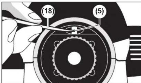
nanaangnauaaunan (4) nyaanu (5) 10
nuu (18) annnnnaaannnnnnae nnne B
yannnnnnaaannn (4) naun
wnnnn b wannnnn 1.476 u.
Bosch
T
T
nwnnynnnnae nnnnnnne nnnee nnnnnnne
y
mnnnnnnaaannnnnnnnnnnnnnnnnnnnnnnnnnnnnnnnnnnnnnnnnnnnnnnnnnnnnnnnnnnnnnnnnnnnnnnnnnnnnnnnnnnnnnnnnnnnnnnnnnnnnnnnnn
nnaaannnnn nnaanennnnae aen ane ane ane ane ane ane ane ane ane ane ane ane ane ane ane ane ane ane ane ane ane ane ane ane ane ane ane ane ane ane ane ane ane ane ane ane ane ane ane ane ane ane ane ane ane
nnu
ywnnnnnaaannnnnnaanennnnnnnnnnnnnnnnnnnnnnnnnnnnnnnnnnnnnnnnnnnnnnnnnnnnnnnnnnnnnnnnnnnnnnnnnnnnnnnnnnnnnnnnnnnnnnnnnnnnnnnnnnnnnnnnnnnnnnnnnnnnnnnnnnnnnnnnnnnnnnn nn nannnannnannnannnannnannnannnannnannnannnannnannnannnannnannnannnannnannnannnannnannnannnannnannnannnannnannnannnannnannnannnannnannnannnannnannnannnannnannnannnannnannnannnannnannnannnannnannnannnannnann
www.bosch-pt.com/serviceaddresses
T
y
Bahasa Indonesia
www.bosch-pt.com/serviceaddresses
Caramembuang
www.bosch-pt.com/serviceaddresses
Su'thai bo
Dung cu do, phu kien va bao bi phai duoc phan loai de tai che theo huong than thien voi mi truong.
jgaaall jk
wJll ooc gwsj jgwaal jg j Siiu w. aubusill pwwll aao 1c oogagall
(1)ddwdwsc
(2)jolitigog lalilg 1
(3)jIjIg jLoJwIJI J
(4) aaii jaii iiai 1a.
(5)agjll 1
(6)
(7) (5)
(8)1L
(9)gX1nJp 19
10)
(11) (jil jilililililililililililililililililililililililililililililililililililililililil
(12) p dJI JIJIJIJIJJIJIJIJIJIJIJIJIJIJIJIJIJIJIJIJIJIJIJIJIJIJIJIJIJIJIJIJIJIJIJIJIJIJIJIJIJIJIJIJIJIJIJIJIJIJIJIJIJIJIJIJIJIJIJIJIJIJIJIJIJIJIJIJIJIJIJIJIJIJIJIJIJIJIJIJIJIJIJIJIJIJIJIJIJIJIJIJIJIJIJIJIJIJIJIJIJIJIJIJIJ
(13) (Lc) 5/8 pIgai JU
(w)
(14)UlaJI
1Jg
aaiI 1
(15)Jusuagai gai jia oogaoai jgai
山
(16)
yaaaiI JlaswKl
(16)
wJU JwUdUe 17
bdo 18
dua (19)
Jg9w (20)
20.4gssalglggsalglglls
gll liol jol gill
aaii iiaai aaii
JauaawlloLgI Iaasagaa
gjllg LwJg J
aJI UuJI
Robert Bosch Morocco SARL
gJoojll 53
20300
+212529314327:
sav.outillage@ma.bosch.com: 一 gjSJ|
:aa aai juglc jajll
www.bosch-pt.com/serviceaddresses
auijseJoo jaiil
gulgul g uall scc no jalll y jol lqauu ujub nac aull ccl abilaoaabu. guailldy kyll
olkiwJjglgla
Jai jui jia jia jia jia jia jia jia jia jia jia jia jia jia jia jia jia jia jia jia jia jia jia jia jia jia jia jia jia jia jia jia jia jia jia jia jia jia jia jia jia
gi 1
| GOL 32 G | GOL 32 D | GOL 26 G | GOL 26 D | GOL 20 G | GOL 20 D | jlrjbjbjbjbjbjbjbjbjbjbjbjbjbjbjbjbjbjbjbjbjbjbjbjbjbjbjbjbjbjbjbjbjbjbjbjbjbjbjbjbjbjbjbjbjbjbjbjbjbjbjbjbjbjbjbjbjbjbjbjbjbjbjbjbjbjbjbjbjbjbjbjbjbjbjbjbjbjbjbjbjbjbjbjbjbjbjbjbjbjbjbjbjbjbjbjbjbjbjbjbj | jlrjbjbjbjbjbjbjbjbjbjbjbjbjbjbjbjbjbjbjbjbjbjbjbjbjbjbjbjbjbjbjbjbjbjbjbjbjbjbjbjbjbjbjbjbjbjbjbjbjbjbjbjbjbjbjbjbjbjbjbjbjbjbjbjbjbjbjbjbjbjbjbjbjbjbjbjbjbjbjbjbjbjbjbjbjbjbjbjbjbjbjbjbjbjbjbj | jlrj |
| 3601 K68 501 | 3601 K68 500 | 3601 K68 001 | 3601 K68 000 | 3601 K68 401 | 3601 K68 400 | jlrjbjbjbjbjbjbjbjbjbjbjbjbjbjbjbjbjbjbjbjbj | jlrj | |
| 120 m | 120 m | 100 m | 100 m | 60 m | 60 m | jlrj | jlrj | |
| 1 mm/30 m | 1 mm/30 m | 1,6 mm/30 m | 1,6 mm/30 m | 3 mm/30 m | 3 mm/30 m | jlrj | jlrj | |
| 1,0 mm | 1,0 mm | 1,5 mm | 1,5 mm | 2,5 mm | 2,5 mm | jlrj | jlrj | |
| 8'/2 mm | 8'/2 mm | 8'/2 mm | 8'/2 mm | 8'/2 mm | 8'/2 mm | jlrj | jlrj | |
| (jlrj)S | jlrj | |||||||
| ±15' | ±15' | ±15' | ±15' | ±15' | ±15' | jlrj | jlrj | |
| ● | ● | ● | ● | ● | ● | jlrj | jlrj |
162|
alolj jl as sl abai (g) 1s ojl jj1 s jSao gw sOjsl July jbi
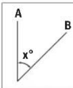
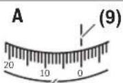
(10) (10)

JUWgabaiA dbai dy jyjoliljj JUOuLCLauai daaow ndiyj ybjl .uK UJLaoJysooJyduaai (10) JIJIuww.uyuJy9)SydyuJUw coLc .uK UJW gabai Bdbai dy jy6oJydl .uJglj (9)SydyuJUW coLc JyUglj uglj :GOL 20 D/GOL 26 D/GOL 32D 45^ :UJooosu oJsi Uglj :GOL 20 G/GOL 26 G/GOL 32 G .45 gon:UJooosu oJsi
j0j1j1j1 jiiS
jIJI Jai g jI JUJnuaa g jEgwh jI juai I a g jI j Cgcb Su OjS il .i S wjj | yg oJil JJI
g s j l j s o g a
jIjUgSASJgS OJSLJlJ 1sIgUgUdAsuusu(12)olwJ (7)SgJSJJJJ 1sIgUgUdAsuusu180°JgSsuJ (7)SgJSJJJgS
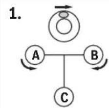

Igw yB gA jju dU Jgl g uu uu uu uu U 1
. 1Jg 1j 1u 1u 1u 1u 1u 1u 1u 1u 1u 1u 1u 1u 1u 1u 1u 1u 1u 1u 1u 1u 1u 1u 1u 1u 1u 1u 1u 1u 1u 1u 1u 1u 1u 1u
gljai g jg jj jjglj jl j
jI bgi jgabu cui jil j
siog o jlgio g jz (jglwias) oii
oji jbl jllio slj pabi jgb a JL
1g w u L d sis U
(3)jlju jj jgim
Sgj jj1 j0a (s) joo
abai s 15gj y j 15gj ojl si jj 15gj oj gj 20) 15gj w jL jL jS k jS ooi jj 15s cJ L J S k jgl dU dw C uui jj 15d w L aL b U dU w 15g j 15g ojl si .sik jI g pabi i oo j abai 15gj l 15g ojl si
gSul (ugsga) jjjaogai 1 (1) ww wscjI j bao wgj
Jg Jw S Caw d J gSui
aw 1g g g uaiu
. (1) w Lw dc lg
jwi jia jy j (6) w Lw
. g w luoi oow lols g aglg
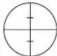
$$ \left. \right.\left. \right.\left. \right.\left. \right.\left. \right.\left. \right.\left. \right.\left. \right.\left. \right.\left. \right.\left. \right.\left.\left.\left.\left.\left.\left.\left.\left.\left.\left.\left.\left.\left.\left.\left.\left.\left.\left.\left.\left.\left.\left.\left. \text {S} _ {2} \right]\right]\right]\right]\right]\right]\right]\right]\right]\right]\right]\right]\right]\right]\right]\right]\right]\right]\right]\right]\right]\right]\right] $$
$$ 1, 4 7 6 \mathrm {m} \pm 2 \mathrm {m m} $$
(5)diw)ogj jilw sdo (uJg
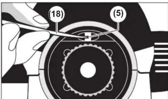
jBwgi. jI (4) GwGwGw
Cg CgLg (5) paiy 18) paii
pilu li, yiajuycuiw uac cs
oaw dawao Jsao B aoo yaaow j sju ojlil .sgw Jolb2 elajgl yglbo
. dy iJ 4 (4) GwGwGw
:Jio
. gwi 1,476 m Jsao ylu b2 sjo ojlil
[5g]jji 10000000000
:duolj j jdoa jjw www.bosch-pt.com/serviceaddresses
olwJjL0jI
yJyLgSsuygclalsojJil jJl gJla oJ jCuwj bdo LcWio gJb .sigw CluJy