
GPL 3 - Laser level BOSCH - Free user manual and instructions
Find the device manual for free GPL 3 BOSCH in PDF.
| Product type | Point laser level |
| Brand | Bosch |
| Model | GPL 3 |
| Working area | 30 m |
| Leveling accuracy | ±0.3 mm/m |
| Self-leveling range | ±5° (longitudinal axis) / ±3° (transverse axis) |
| Leveling time | <4 s |
| Laser class | 2 (635 nm, <1 mW) |
| Power supply | 3 LR6 (AA) batteries 1.5 V |
| Battery life | approx. 24 h |
| Weight | 0.25 kg (according to EPTA 01/2003) |
| Dimensions | 104 x 80 x 40 mm |
| Protection rating | IP 5X |
| Tripod thread | 1/4" |
| Auto shut-off | Adjustable (20 min or 8 h) |
| Operating temperature | -10 °C to +50 °C |
| Storage temperature | -20 °C to +70 °C |
| Max. relative humidity | 90 % |
| Cleaning | Soft, damp cloth (no detergents) |
| Included accessories | Protective case, laser viewing glasses, magnetic mount |
Frequently Asked Questions - GPL 3 BOSCH
User questions about GPL 3 BOSCH
0 question about this device. Answer the ones you know or ask your own.
Ask a new question about this device
Download the instructions for your Laser level in PDF format for free! Find your manual GPL 3 - BOSCH and take your electronic device back in hand. On this page are published all the documents necessary for the use of your device. GPL 3 by BOSCH.
USER MANUAL GPL 3 BOSCH
ORJ-DOK11-13773-002.fm Page 1 Tuesday, September 30, 2008 1:11 PM
Robert Bosch GmbH
on Original Instructions
H
(1) (2)
C
H
Brksarinsngl original
no Original drfinsstruk
fi Akuperaset oheet
ellipoturoobinyxphantc
trOriginal isletmetallmat
Pilnstrukc]qorygina
bgOpHmHnHnHnHnHnHnHnHnHnHnHnHnHnHnHnHnHnHnHnHnHnHnHnHnHnHnHnHnHnHnHnHnHnHnHnHnHnHnHnHnHnHnHnHnHnHnHnHnHnHnH
m = 311 ;
18


Deutsch . 4
English. 11
Francais. 19
Espanol. 26
Portugués. 33
Italiano.. 40
Nederlands.. 47
Dansk. 54
Svenska Sida 60
Norsk. Side 66
Suomi 72
EayniKa ... 78
Türkce Sayfa 86
Polski. Strona 92
Cesky Strana 99
Slovensky. Strana 106
Magyar. Oldal 113
Pycckn .. CtpaHua 120
YkpaHcbka. .CtoPiHa 128
Româna . . . . . . . . . . . . . . . . . . . . . . . . . . . . . . . . . . . . . . . . . . . . . . . . . . . . . . . . . . . . . . . . . . . . . . . . . . . . . . . . . . . . . . . . . . .
21 × 21 236
2607002195
4 | Deutsch
Sicherheitshinweise
Punktlaser

Working safely with the measuring tool is possible only when the operating and safety information are read completely and the instructions contained therein are strictly
followed. Never make warning labels on the measuring tool unrecognisable. SAVE THESE INSTRUCTIONS.
- Caution - The use of other operating or adjusting equipment or the application of other processing methods than those mentioned here, can lead to dangerous radiation exposure.
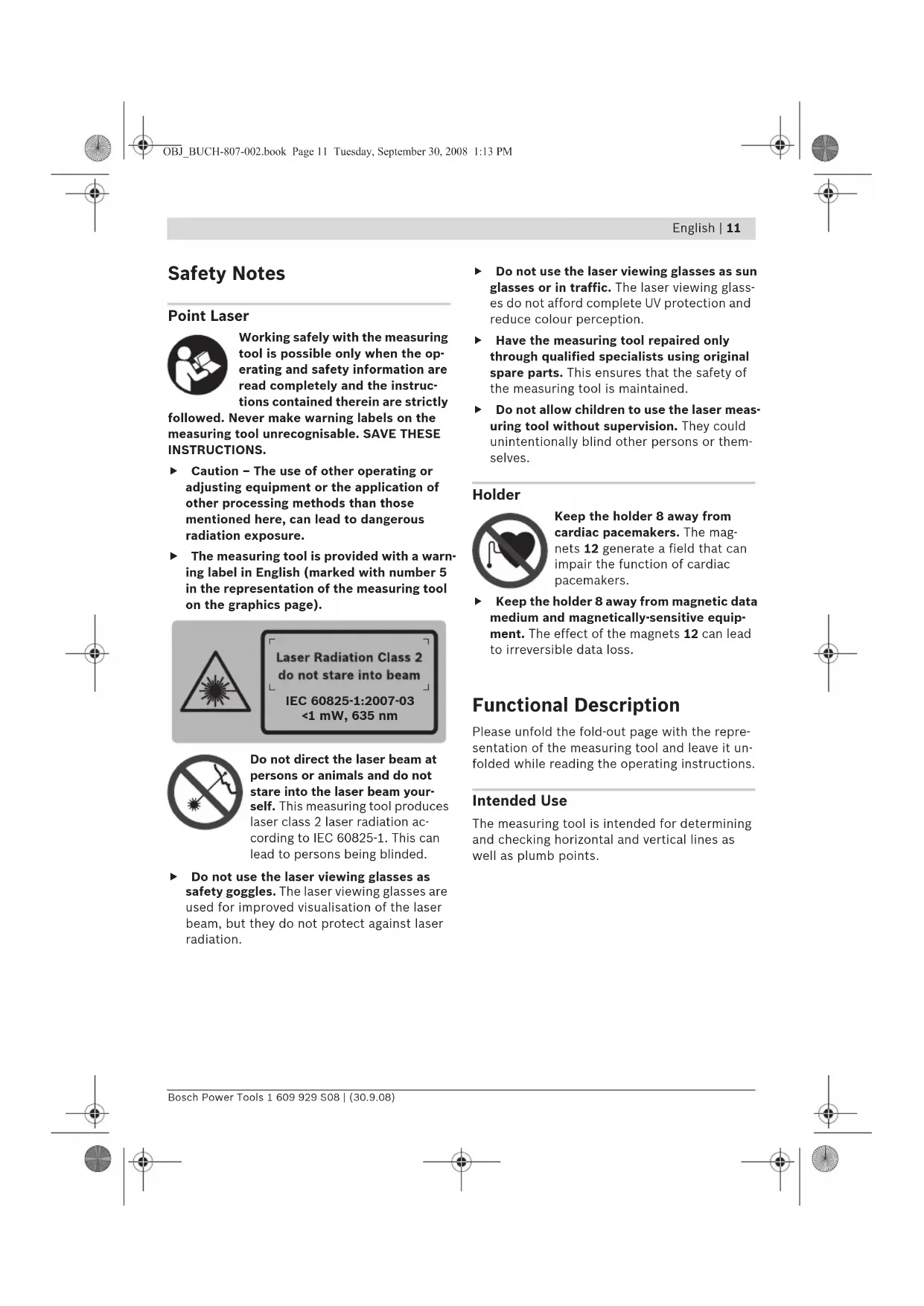
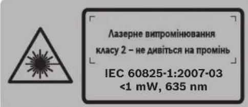
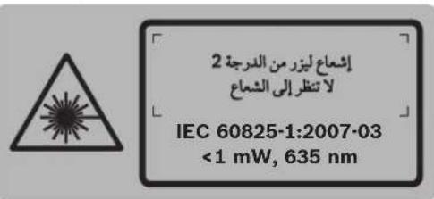
The measuring tool is provided with a warning label in English (marked with number 5 in the representation of the measuring tool on the graphics page).
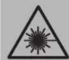
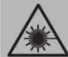
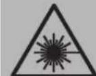
Laser Radiation Class 2 do not stare into beam
IEC 60825-1:2007-03 <1 mW, 635 nm
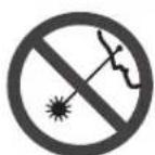
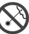
Do not direct the laser beam at persons or animals and do not stare into the laser beam yourself. This measuring tool produces laser class 2 laser radiation according to IEC 60825-1. This can lead to persons being blinded.
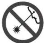
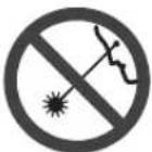
Do not use the laser viewing glasses as safety goggles. The laser viewing glasses are used for improved visualisation of the laser beam, but they do not protect against laser radiation.
Do not use the laser viewing glasses as sun glasses or in traffic. The laser viewing glasses do not afford complete UV protection and reduce colour perception.
Have the measuring tool repaired only through qualified specialists using original spare parts. This ensures that the safety of the measuring tool is maintained.
Do not allow children to use the laser measuring tool without supervision. They could unintentionally blind other persons or themselves.
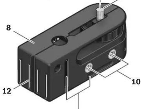
Holder

Keep the holder 8 away from cardiac pacemakers. The magnets 12 generate a field that can impair the function of cardiac pacemakers.
- Keep the holder 8 away from magnetic data medium and magnetically-sensitive equipment. The effect of the magnets 12 can lead to irreversible data loss.
Functional Description
Please unfold the fold-out page with the representation of the measuring tool and leave it unfolded while reading the operating instructions.
Intended Use
The measuring tool is intended for determining and checking horizontal and vertical lines as well as plumb points.
12 | English
Technical Data
| Point Laser GPL 3 | |
| Professional | |
| Article number | 3 601 K66 1.. |
| Working range | 30 m |
| Levelling Accuracy | ± 0.3 mm/m |
| Self-levelling range (typical) alongside the - longitudinal axis | ± 5° |
| - lateral axis | ± 3° |
| Levelling duration, typically | <4 s |
| Operating temperature | -10 °C ... +50 °C |
| Storage temperature | -20 °C ... +70 °C |
| Relative air humidity, max. | 90 % |
| Laser class | 2 |
| Laser type | 635 nm, <1 mW |
| Tripod mount | 1/4" |
| Batteries | 3 x 1 . 5 V L R 6 (A |
| Operating life time, approx. | 24 h |
| Weight according to EPTA-Procedure 01/2003 | 0.25 kg |
| Dimensions | 104 x 80 x 40 mm |
| Degree of protection | IP 5X |
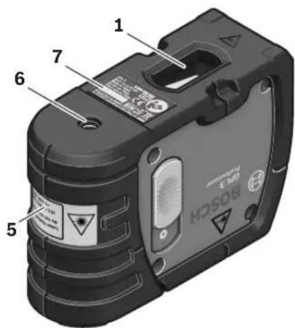
Please observe the article number on the type plate of your measuring tool. The trade names of the individual measuring tools may vary.
The measuring tool can be clearly identified with the serial number 7 on the type plate.
Product Features
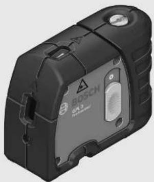
The numbering of the product features shown refers to the illustration of the measuring tool on the graphic page.
1 Exit opening for laser beam
2 Latch of battery lid
3 Battery lid
4 On/Off switch
5 Laser warning label
6 Tripod mount 1/4"
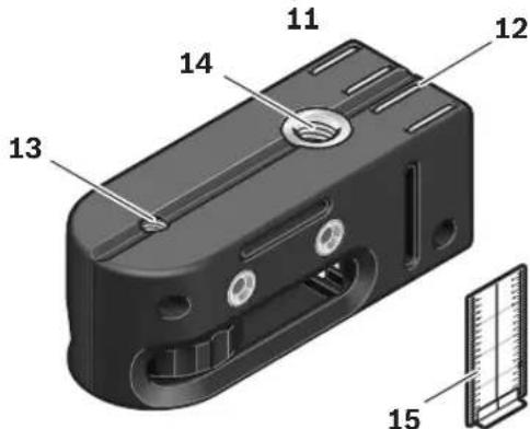
7 Serial number
8 Holder
9 Locking screw for holding device
10 Screw holes of holder
11 Opening for strap attachment
12 Magnets
13 1/4" tripod mount on holder
14 5/8" tripod mount on holder
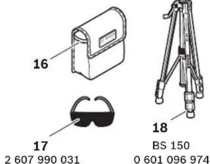
15 Measurement plate with stand
16 Protective case
17 Laser viewing glasses
18 Tripod*
*Accessories shown or described are not part of the standard delivery scope of the product. A complete overview of accessories can be found in our accessories program.
Assembly
Inserting/Replacing the Battery
Alkali-manganese batteries are recommended for the measuring tool.
To open the battery compartment 3, turn the latch 2 in clockwise direction to position and pull off the battery lid. Insert the batteries provided. When inserting, pay attention to the correct polarity according to the representation on the inside of the battery compartment.
Position the battery lid to the bottom of the housing and then push it upward. To lock the battery lid, turn the latch 2 in anticlockwise direction to the position.
When the laser beams flash slowly during operation, the batteries are low. When the flashing begins, the measuring tool can be operated for approx. 8 h.
Always replace all batteries at the same time. Only use batteries from one brand and with the identical capacity.
Remove the batteries from the measuring tool when not using it for extended periods.
When storing for extended periods, the batteries can corrode and discharge themselves.

Operation
Initial Operation
Protect the measuring tool against moisture and direct sun irradiation.
Do not subject the measuring tool to extreme temperatures or variations in temperature. As an example, do not leave it in vehicles for longer periods. In case of large variations in temperature, allow the measuring tool to adjust to the ambient temperature before putting it into operation. In case of extreme temperatures or variations in temperature, the accuracy of the measuring tool can be impaired.
- Avoid heavy impact or falling of the measuring tool. After heavy exterior impact on the measuring tool, an accuracy check should always be carried out before continuing to work (see "Levelling Accuracy").
- Switch the measuring tool off during transport. When switching off, the levelling unit, which can be damaged in case of intense movement, is locked.
Switching On and Off
To switch on the measuring tool, push the On/Off switch 4 upward so that "I" is indicated on the switch. Immediately after switching on, the measuring tool sends a laser beam out of each exit opening 1.
Do not point the laser beam at persons or animals and do not look into the laser beam yourself, not even from a large distance.
To switch off the measuring tool, push the On/Off switch 4 downward so that "0" is indicated on the switch. When switching off, the levelling unit is locked.
Setting the Automatic Switch-off
By default, the measuring tool automatically shuts off 20 minutes after being switched on.
The automatic switch-off can be set from 20 minutes to 8 hours. For this, switch the measuring tool on, then immediately off, and then on again within 4 s. To confirm the change, all laser beams will flash quickly for 2 s after switching on the second time.
Do not leave the switched on measuring tool unattended and switch the measuring tool off after use. Other persons could be blinded by the laser beam.
When switching on the measuring tool the next time, the automatic switch-off is set to 20 minutes again.
Working with Automatic Levelling
Position the measuring tool on a level and firm support, attach it to the holder 8 or to the tripod 18.
After switching on, the automatic levelling function automatically compensates irregularities within the self-levelling range from ± 5^ (longitudinal axis) and ± 3^ (lateral axis). The levelling is finished as soon as the laser points do not move any more.
If the automatic levelling function is not possible, e.g. because the surface on which the measuring tool stands deviates by more than 5^ or 3^ from the horizontal plane, the laser beams flash rapidly. In this case, bring the measuring tool to the level position and wait for the self-levelling to take place. As soon as the measuring tool is within the self-levelling range of ± 5^ or ± 3^ respectively, all laser beams light up continuously again.
In case of ground vibrations or position changes during operation, the measuring tool is automatically levelled in again. To avoid errors by moving the measuring tool, check the position of the laser beams with regard to the reference points upon re-levelling.
14 | English
Levelling Accuracy
Influences on Accuracy
The ambient temperature has the greatest influence. Especially temperature differences occurring from the ground upward can divert the laser beam.
As thermal fluctuation is largest close to the ground, the measuring tool, if possible, should be mounted on a commercially available tripod and placed in the centre of the working area.
Apart from exterior influences, device-specific influences (such as heavy impact or falling down) can lead to deviations. Therefore, check the accuracy of the measuring tool each time before starting your work.
Should the measuring tool exceed the maximum deviation during one of the tests, please have it repaired by a Bosch after-sales service.
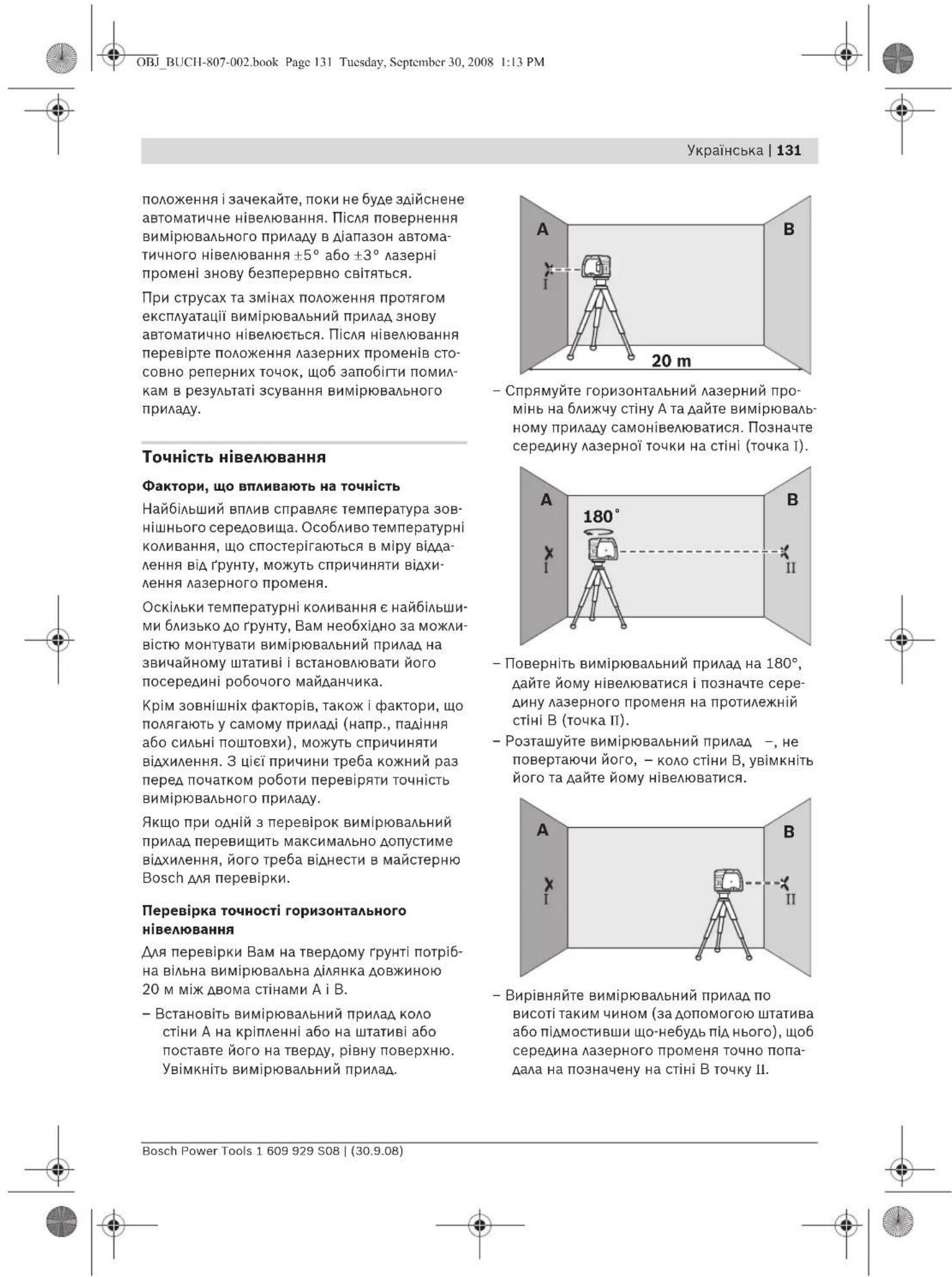
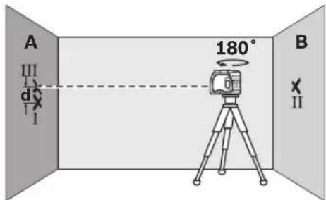
Checking the Horizontal Levelling Accuracy
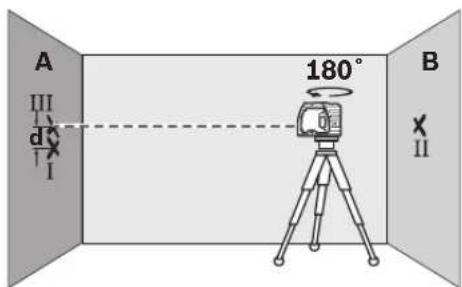
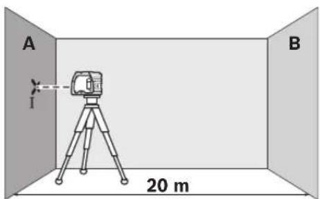
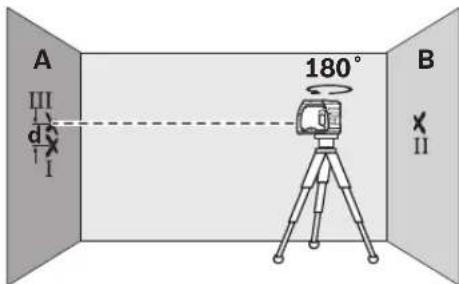
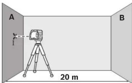
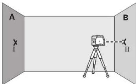
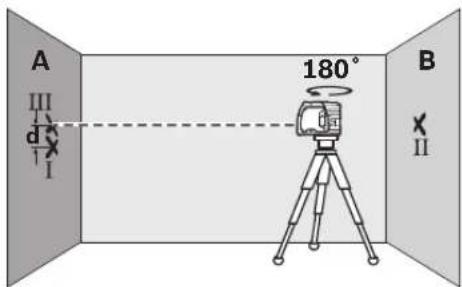
A free measuring distance of 20m on a firm surface between two walls A and B is required for the check.
Mount the measuring tool onto the holder or a tripod, or place it on a firm and level surface close to wall A. Switch the measuring tool on.
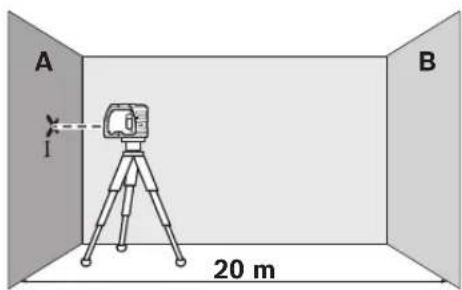
- Direct the horizontal laser beam against the close wall A and allow the measuring tool to level in. Mark the centre of the laser beam on the wall (point 1).
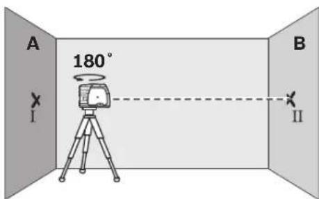
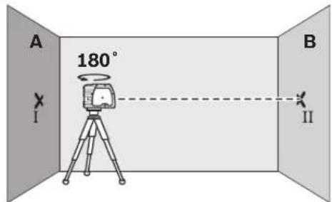
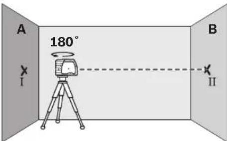
- Turn the measuring tool around by 180^ , allow it to level in and mark the centre point of the laser beam on the opposite wall B (point 11).
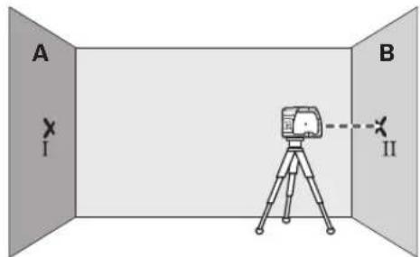
- Without turning the measuring tool, position it close to wall B. Switch the measuring tool on and allow it to level in.
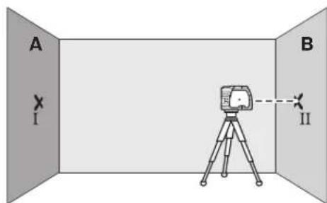
Align the height of the measuring tool (using the tripod or by underlaying, if required) in such a manner that the centre point of the laser beam is projected exactly against the previously marked point II on wall B.
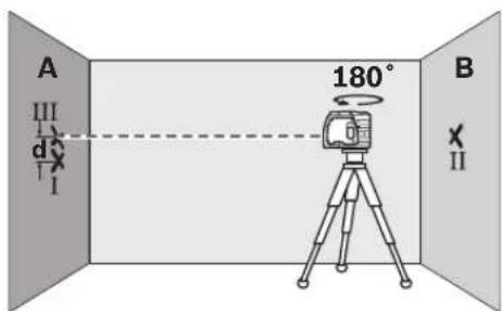
- Rotate the measuring tool by 180^ without changing the height. Allow it to level in and mark the centre point of the laser beam on wall A (point III). Take care that point III is as vertical as possible above or below point I.
The difference d of both marked points I and III on wall A indicates the actual height deviation of the measuring tool.
On the measuring distance of 2 × 20 m = 40 m , the maximum allowable deviation is: 40 m × ± 0.3 mm/m = ± 12 mm .
Thus, the difference d between points I and III may not exceed 12 mm (max.).
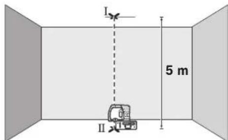
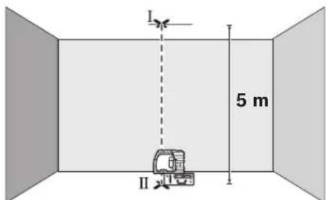
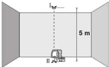
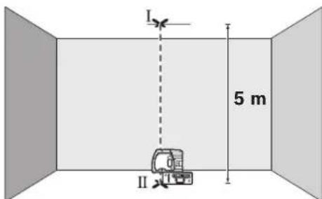
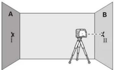
Checking the Vertical Levelling Accuracy
For this check, a free measuring distance of approx. 5m between floor and ceiling on a firm surface is required.
- Draw a straight line on the ceiling.
- Mount the measuring tool to the holder or a tripod. Switch the measuring tool on and rotate it in such a manner that the bottom plumb beam can be seen on the floor.
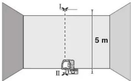
- Position the measuring tool in such a manner that the upper plumb beam points against the line on the ceiling. Allow the measuring tool to level in. Mark the centre of the upper laser point on the line on the ceiling (point I). Also, mark the centre of the laser point on the floor (point II).
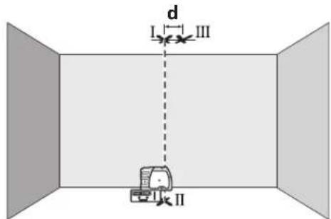
- Rotate the measuring tool by 180^ . Position it in such a manner that the centre of the bottom laser point is directed on the already marked point II and the upper laser point is directed against the line on the ceiling. Allow the measuring tool to level in. Mark the centre of the upper laser point on the line on the ceiling (point III).
The difference d of both marked points I and III on the ceiling results in the actual deviation of the measuring tool to the plumb line.
On the measuring distance of 2 × 5m = 10m , the maximum allowable deviation is: 10m × ± 0.3mm / m = ± 3mm .
Thus, the difference d between points I and III must not exceed 3 mm (max.).
16 | English
Working Advice
Always use the centre of the laser point for marking. The size of the laser point changes with the distance.
Attaching with the Holder
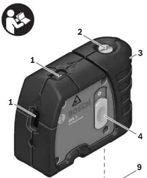
To fasten the measuring tool on the holder 8, screw the locking screw 9 of the holder into the 1/4 tripod mount 6 on the measuring tool and tighten. To rotate the measuring tool on the holder, slightly loosen the screw 9.
- Rotate the measuring tool on the holder 8 sideward or toward the rear to make the bottom plumb beam visible.
- Rotate the measuring tool on the holder 8 to project heights with the horizontal laser beam.
With the holder 8, the measuring tool can be attached as follows:
- Mount the holder 8 to the tripod 18 or a commercially available camera tripod via the 1/4'' tripod mount 13. For fastening to a commercially available construction tripod, use the 5/8'' tripod mount 14.
- The holder 8 can be fastened to step on use the laser viewing glasses as sun via the magnets 12. glasses or in traffic. The laser viewing glass
- The holder 8 can be fastened to dry walls not afford complete UV protection and wood walls with screws. For this, insert reduce colour perception. screws with a minimum length of 50mm into the screw holes 10 of the holder.
- The holder 8 can also be fastened to pipes or similar beams using a commercially available strap by threading it through the opening 11 for strap attachment.
Do not use the laser viewing glasses as safety goggles. The laser viewing glasses are used for improved visualisation of the laser beam, but they do not protect against laser radiation.
ste do nce use the laser viewing glasses as sun glasses or in traffic. The laser viewing glass- drowns not afford complete UV protection and reduce colour perception.
Working with the Tripod (Accessory)
A tripod 18 offers a stable, height-adjustable measuring support. Place the measuring tool via the tripod mount 6 onto the 1/4'' male thread of the tripod and screw the locking screw of the tripod tight.
Working with the Measuring Plate (Accessory)
With the measuring plate 15, it is possible to project the laser mark onto the floor or the laser height onto a wall.
With the zero field and the scale, the offset or drop to the required height can be measured and projected at another location. This eliminates the necessity of precisely adjusting the measuring tool to the height to be projected.
The measuring plate 15 has a reflective coating that enhances the visibility of the laser beam at greater distances or in intense sunlight. The brightness intensification can be seen only when viewing, parallel to the laser beam, onto the measuring plate.
Laser Viewing Glasses (Accessory)
The laser viewing glasses filter out the ambient light. This makes the red light of the laser appear brighter for the eyes.
Maintenance and Service
Maintenance and Cleaning
Store and transport the measuring tool only in the supplied protective case.
Keep the measuring tool clean at all times.
Do not immerse the measuring tool into water or other fluids.
Wipe off debris using a moist and soft cloth. Do not use any cleaning agents or solvents.
Regularly clean the surfaces at the exit opening of the laser in particular, and pay attention to any fluff of fibres.
If the measuring tool should fail despite the care taken in manufacturing and testing procedures, repair should be carried out by an authorized after-sales service centre for Bosch power tools.
In all correspondence and spare parts orders, please always include the 10-digit article number given on the type plate of the measuring tool.
In case of repairs, send in the measuring tool packed in its protective case 16.
After-sales Service and Customer Assistance
Our after-sales service responds to your questions concerning maintenance and repair of your product as well as spare parts. Exploded views and information on spare parts can also be found under:
www.bosch-pt.com
Our customer consultants answer your questions concerning best buy, application and adjustment of products and accessories.
Great Britain
Robert Bosch Ltd. (B.S.C.)
P.O.Box 98
Broadwater Park
North Orbital Road
Denham
Uxbridge
UB95HJ
Tel. Service: +44 (0844) 736 0109
Fax: +44 (0844) 736 0146
Australia, New Zealand and Pacific Islands
Robert Bosch Australia Pty. Ltd.
Power Tools
Locked Bag 66
Clayton South VIC 3169
Customer Contact Center
Inside Australia:
Phone: +61 (01300) 307 044
Fax: +61 (01300) 307 045
Inside New Zealand:
Phone: +64 (0800) 543 353
Fax: +64 (0800) 428570
Outside AU and NZ:
Phone: +61 (03) 9541 5555
www.bosch.com.au
People's Republic of China
Website: www.bosch-pt.com.cn
China Mainland
Bosch Power Tools (China) Co., Ltd.
567, Bin Kang Road
Bin Jiang District 310052
Hangzhou, P.R.China
Service Hotline: 800 8 20 84 84
Tel.: +86 (571) 87 77 43 38
Fax: +86 (571) 87 77 45 02
HK and Macau Special Administrative Regions
Robert Bosch Hong Kong Co. Ltd.
21st Floor, 625 King's Road
North Point, Hong Kong
Customer Service Hotline: +852 (21) 02 02 35
Fax: +852 (25) 90 97 62
E-Mail: info@hk.bosch.com
www.bosch-pt.com.cn
Indonesia
PT. Multi Tehaka
Kawasan Industri Pulogadung
Jalan Rawa Gelam III No. 2
Jakarta 13930
Indonesia
Tel.: +62 (21) 4 60 12 28
Fax: +62 (21) 46826823
E-Mail: sales@multitehaka.co.id
www.multitehaka.co.id
18 | English
Philippines
Robert Bosch, Inc.
Zuellig Building
Sen. Gil Puyat Avenue
Makati City 1200, Metro Manila
Philippines
Tel.: +63 (2) 8173231
www.bosch.com.ph
Malaysia
Robert Bosch (SEA.) Pte. Ltd.
No. 8a, Jalan 13/6
46200 Petaling Jaya,
Selangor,
Malaysia
Tel.: +6 (03) 7966 3000
Fax: +6 (03) 7958 3838
E-Mail: hengsiang.yu@my.bosch.com
Toll Free Tel.: 1800 880 188
Fax:+60379583838
www.bosch.com.sg
Thailand
Robert Bosch Ltd.
Liberty Square Building
No.287,11 Floor
Silom Road, Bangrak
Bangkok 10500
Tel.: +66 (2) 631 18 79 - 18 88 (10 lines)
Fax: +66 (2) 2384783
Robert Bosch Ltd., P. O. Box 2054
Bangkok 10501, Thailand
Bosch Service - Training Centre
2869-2869/1 Soi Ban Kluay
Rama IV Road (near old Paknam Railway)
Prakanong District
10110 Bangkok
Thailand
Tel.: +66 (2) 671 7800-4
Fax: +66 (2) 249 42 96
Fax: +66 (2) 2495299
Singapore
Robert Bosch (SEA.) Pte. Ltd.
38 C Jalan Pemimpin
Singapore 915701
Republic of Singapore
Tel.: +65 (3) 50 54 94
Fax: +65 (3) 50 53 27
www.bosch.com.sg
Vietnam
Robert Bosch (SEA) Pte. Ltd - Vietnam
Representative Office
Saigon Trade Center, Suite 1206
37 Ton Duc Thang Street,
Ben Nghe Ward, District 1
HCMC
Vietnam
Tel.: +84 (8) 9111 374 - 9111 375
Fax: +84 (8) 9111376
Disposal
Measuring tools, accessories and packaging should be sorted for environmental-friendly recycling.
Only for EC countries:
Do not dispose of measuring tools into household waste!
According the European Guideline 2002/96/EC for Waste Electrical and Electronic Equipment and its implementation into national
right, measuring tools that are no longer usable must be collected separately and disposed of in an environmentally correct manner.
Battery packs/batteries:
Do not dispose of battery packs/batteries into household waste, fire or water. Battery packs/ batteries should be collected, recycled or disposed of in an environmental-friendly manner.
Only for EC countries:
Defective or dead out battery packs/batteries must be recycled according the guideline 91/157/EEC.
Batteries no longer suitable for use can be directly returned at:
Great Britain
Robert Bosch Ltd. (B.S.C.)
P.O.Box 98
Broadwater Park
North Orbital Road
Denham
Uxbridge
UB95HJ
Tel. Service: +44 (0844) 736 0109
Fax:+440844)7360146
Subject to change without notice.


Francais | 19
Robert Bosch (France) S.A.S.
Service ApreS-Vente Electroportatif
Bosch Service Center
Telegrafvej 3
2750 Ballerup
Tel. Service Center: +45 (4489) 8855
Fax: +45 (4489) 87 55
E-Mail: vaerktoej@dk.bosch.com
Bortskaffelse
Bosch Service Center
Telegrafvej 3
2750 Ballerup
Danmark
Tel.: +46 (020) 41 44 55
Fax: +46 (011) 187691
Avfallshantering
Endast for EU-lander:
Suvtnpnon kal Service
Suvtnponkai kaθapiooC
Na diaquayete kai va metapepe To epyaieo metponoc mvo oea otnv npootateutikn taovtou to ouvodeuei.
Na δiatnpelTe To epyaleo μeTpnonc navta kaθapò.
Mn Buioaero to epyaaleo metpnonc oe vepo n oe aaaa uypa.
Kaθapiçeteuovpouockaibpwucμ'eva uypo,paλakopnvi.Mn xnpaonoiitepeaa Kaθapiou n diautec.
Na kaθaipizete taktika idialtepa tic enipaveiec kovt aTnV eEdoToC aKtivac leeep kal va npooexete va un dnoupyouvtai xvoudia.
Av npolec tic enmuelnevec e0oouc kataokueuc kal elvyou otaatnoe i kantoTo epyaleio metpnonc, toe n eniakun tou npenei vaavateei oe eva eouoiodotnveo uvepyeo yia nkeptikc epyaleia tnc Bosch.
NapakaLoupe,otav kavete diaaaqntikc epwthneic kaowc kai kata nyn npayelia avtalaaktkov,va aapepe tnavote to 10nphi apetoo eupetnpoiou nou pbioketa nny nivakiokaatakeuaon tou epyaieiou mepnonc.
To epyaleo etpnoic npenei va anooteai yia enkeun eo aonv npoataeutik thkn 16.
Eaynvika185
Tnpoue to dukaiwma aalayov.
86 | Türkiye
Güvenlik Talimati
Noktasal distomat

Bosch San. ve Tic. A.S.
Ahi Evran Cad. No:1 Kat:22
Polaris Plaza
80670 Maslak/Istanbul
Müsteri Danisman: +90 (0212) 335 06 66
Müsteri Servis Hatti: +90 (0212) 335 07 52
Tasfiye
Robert Bosch Sp. z o.o.
Bosch Service Center PT
K Vapence 1621/16
692 01 Mikulov
He yctanaBaHbAte DepeXaTeAb 8 B6An3n KapdnoCTHMyAToPOB. MarHHTb1 12 co3aIoT MaHHTHOe IIOAE, KOtOpoe MoKET OKa3bIBaTb BAnHHne Ha pa6Oy KaPdNOCTHMyAToPA.
DepxnteepkaTeB8BaAnOTMaHHTbIX HocHTeae DaHHbIX NOTpN6OpOB, yBCTBnTeABHbIM K MaHHTHOMy TNOAIO. AeIcTBne MaHTOB 12 MoKet PnBOaNTb K HeBOcTOnAHNMOI TIOTepe DaHHbIX.
OtncaHne yHKn
TkoAyncta,OTKpoTe packAadHyo cTpaHnucy C HIOCTpaaHmN HcTpymenta N OCTaBnIe ee OTkpblto,POKa Bbl H3yaeTe pyKOBoDCTBO n EKcnayataun.
PpHMeHeHne Tn Ha3HaueHnIO
I3MePHTeAHyBm HnCTpyMeH TpeHa3HaueH DAn OtnpeAeHnH N IpoBepKn rOpH0HTaAHybIX BepTnKaAHyBix AHHN N OTBeCOB.
Pycckn | 121
TexHHueckne daHbIe N3o6paXeHHbIe coCTaHBIe qactN
Pa6ota c HhctpyMeHToM
3KcTMyatauia
3aunuatae H3MepeHteAhbHn HnCTpymEnOT BAarN nPpMaBIX COAHeHbIX Auyen.
He NOBepraTe H3MEpHTeABHbI INHCTpyMeHT BO3DeEChTBHO 3KCTpeMaABHbIX TEMPePATy IN TEMEPATyPBIM NepaAM. B qactHOCTn, He OCTaBAJTE ero Ha dNTeABHoebPemB MaunHe. Pn6oBuxN pepeTAdxTEMPEPATpyCHaAaDAte H3MEpHTeABHOMYINHCTpyMeHTy CtaBnANHPoBaTb TEMpePATpy, TpeXde Yem HaunHaTb pa60TaTb C Hm. 3KCTpeMaABHbIE TEMPEPATpyBI IN TEMpePATHyIe PePeTAbMoYOTpUaTeABHO BAHTb HA TOHOCb H3MEpHTeABHO INHCTpyMeHTa.
3aunuahe H3MepeHbHbHnHnCTpymEnOT CnAbHbIX yApOB HnAeHn. Tocae CNBHO HapyXHOro BO3DeHCTBnHa H3MepeHTeABHbN INCHPTpEmHT HeoXoHMo IpeAdIPOdoXeHHem pa6Otbl BcERda IPOBeprToHOCb (CM.《TOuHOCT HnBEAnpoBaHNs).
Ptp TaHCTOpTnOBKe BbIKIOaHTe N3Me pHTeBbHbI HcTpymEt. Pp BbIKIOueHH 6IoKpyETcMaRTHKnOBbIMexaHN3M, KOTOp bI HAue Pp pe3Kx ABHXeHHx MoKeT 6bIt IOBpeXeH.
Bkluoyehne/Bbikluoyehne
UTo6bBkAIOHTb N3MePHTeBHBHINHCTpyMeHT, IpeEaBHbTe BbIKAOHaTeB 4 BBepx, UTo6bHa BbIKAOHaTeAE CTAIO BnHO «I」. Cpaay IOcAe BkIOueHnN3MePHTeBHBINHCTpyMeHT HaHNHaET N3AYaTb IIO OAnHomy Aa3epHOMy Auyu N3 OTBepCTn1.
He HApBaHnTe Aa3epHbI Auy Ha IIOeHN XNBOThbIX Hc CMOTpHTe Camn B Aa3epHbI Auy, BKAOyA Hc 6oAoBwO r pacCToHNA.
UTo6bBbIKAOHTbN3MePnteHbHbINHCTpyMeHT,IIpeaBnHbTe BbIKAOaTeAe 4 BHn3,UTo6bHa BbIKAOaTeAe Ctao BNHO «O».Ipi BBKIO-ueHHMaTHNKOBbMexaHN3M 6ANOkpyETCA
HactpoKa aBToMaTHueCKOrO oTKIAUeHHA
CTaHapTHO n3MepeTebHbI HnCTpyMeT ABOMaTHueCKN OTKIOUaetcyepe3 20 MHN. TocAeBKIOUeyHn.
3To aBTOMaTnueckoe OTKIOUeHne MOXHO IpeHaCTpOntb c 20 MHN. Ha 8 ac. AAn 3TOrOBKHO-HTNE H3MePHTeAHyBn IHCTpyMeHNT, IOCAe 3TOHOHEMeDAEHNO BbIKAOHTe ERO N 3aTEM IOBOTHO BKNIOHTe B TeueHne 4c. B IOATBepxJDeHNe H3MeHeHHBCE Aa3epHBie Ayn6bICTPO MIRAOITIOCAE IOBTOPHORo BKAOUeHn B TeueHne 2c.
He octabnne 6e3 npncmtpa BkIoueHbHn H3MePHTAbHbHn HNCTpyMeH N BblKIOUaHte ero nocae HCIOABoHAHa. ApyTne Aua MoYr 6bIb OCAeTIaehbI a3epHbIM Auyom.
Pn CaeDyUoEeM BKAIOUeHIn H3MepeTaeBHorO HNCTpyMeHTa aBTOMaTHueCKoe OTKIAOUeHHe OITb HaCTpoEHO Ha 20 MHN.
Pa6oTa c aBToMaTHueCKHM HnBeAIpOBAHHeM
YcTaHOBnTe H3MePHTeA hBhI INHCTpyMeHT Ha IpoUHoe rOpN3OHTaHBoe OCHOBaHne n 3aKpeTInTe ero Ha dEpxKaTeNe 8 HA HtATnBE 18.
Iocne BkIoUeHnФyHKnna ABToMaTHueCKOro HNBeAInPOBaHnBbIpaBHBaEt HepOBHocTH BpaMKax dHaIaIa3OHa aBTOMaTHueCKOro HNBeAInPOBaHn ± 5^ (PpOdoIbHaN oCb) NAn ± 3^ (PionepeuHaN oCb). HNBeAInPOBaHnHe 3aBepWeHo, KaT OaBko Aa3epHbIe ToKn Cta6Hn3nPOBaHnCb.
Pycckn | 123
EcAn aBtOMaTHueCKoe HnBeAHPoBaHne HeBO3- MoXHO,HaIP.,ecAn OCHOBAHne,Ha KOTOpom PaTIOAOxEH N3MepHTeABhH II Pn6Op,OTKIo- HeOOTopn30HTaAN 60AE ue Hn 5^ IIN 3^ , A3ePbIe LyuN 6bICTPO MIRaOT. B TaKOM CAYyae YCTaHOBNTe N3MepHTeABHb INHCTpymENT ROpH3OHTaBHO IN IOOXdTE, IOKa Pn6Op HE IPOuN3BeET aBtOMaTHueCKoe CaMOHBeAHPoBAHHe. KaK ToIbKO N3MepHTeABHb INHCTpymENT BEHETcB DAHaTa3OH aBtOMaTHueCKoro HnBEAHPoBAHH ± 5^ IIN ± 3^ ,A3ePbIe LyuN ONITb 6ydy T CBETNbC HnpepbIBHO.
PnCOTpaeHnXnnN3MeHeHHxIIOLOXeHHa BO BpeMa pa6ObTi N3MepnteAhBn HnCTpyMeHT aBTOMaTHueckn CaMOHNBeAHPyETc. Iocne HNBepnoBaHHn PPOBepTe TNOXeHHaIa3epHbIX AuyenTIO OTHoWeHHo K peTepHBm TouKaM, 4TO6bl N36ExaTB OwH60K BpeyBtate CmeEHHa N3MepnteAho HHCTpyMeHTa.
Toohoctb HnBcAIpobaHna
DaKTOpbl,BAHHOUneHaTOuHOCTb
Ha6bwe BnHHe Ha ToHocb OKa3bBaet OKpykaoua Temepatypa. B Oco6eHHoctn n3MeHenr TemepatypbI IO Mepe ydaenr O TpyHTa MOryT BblBbTa bOTKHOeHNr AaepHoro Aya.
Tak KaTe TEmTepaTpHaJ WnXTOBka B6An3H IToA Han6oBbwa, TO N3MePnteBHyI INCTpyMeHT CLeyET, IO BO3MOxHOCTn, YCTaHOBtB Ha WtTaTHe B cepaHe pa6Oey IIOUaAn.
Hapayc BHeuHMn PaKTopaMn OTKAoHeHHN MoYr Bb3bBaTc TaKke N PpUHNaM, KPOUUMNC B CaMOM HMePHTeA hHom HhCTpyMeHTe (HaPmep, NaEHNaM NH CnBbHm ToaKaMn). IoTomy KaJdbn pa3 do HaaHa pa6OtBi IpoBepraTe TocHoCTb H3MePHTeBHOrO HhCTpyMeHTa.
EcnB Bo Bpemr OAnHn3 PPOBepOK H3MepeTbHbN HNCTpymEn TpeBbcNT MaKcMaNbHO AOYCTHMoe OTKaHOHeHne,OTaIte erO B peMOHT B cepBncHyIO MacTepcKyIO Bosch.
PpOBepka TOnHOCTn RopN3OHTaIbHOro HNBeAHPoBaHH
AπPpOBepKnBamHyxHcB6oDhBnH3MepnTeAHBnYyAcTOKHaIpoOHOMOCHOHmMeKdAByMaCTeHaAMNAnBAAHHO20M.
-MoHTnpyTe n3MePnteA hBhI INHCTpyMeHT B6An3n CTeHb IA Ha depXkATEe Hn UTAInBe Hn yCTaHOBHTe erO Ha IIPOuHoe, POBHe OCHOBaHHe. BKIOHTe n3MePnteA hBhINHCTpyMeHT.
-HanpaBbTe rOpHOrTaHbHbIa3epHbI aUy Ha 6AnXHHIO CTeHy A N daTne H3MePHTeHOMy INcTpymEnTy HnBeAInpoBaTbcr.OTMeTbTe cepeHNHy a3epHOToKn Ha cTeHe (toKa1).
-IOBepHnTe N3MepHTeAhBn HNCTpyMeHT Ha 180°, BbXAnTe HNBaHPOBaHne H NtomeTbTe Ha IpoTHBOIOnOxHOH CTHe B cepeAHy Aa3epHoro LyuA (TOUka II).
124 | Pycckn
- YcTaHOBHTe H3MePHTeA6HbH INHCTpyMeH - He IOBOPaUHBA erO - B6An3n CTehBi B, BKAIOHTe ero H daTe emy BpeM HNBENPOBaTbCra.
-BbBepnte n3MePHTaBbHbI INHCTpyMeHT IO Tropn3oHTaAN TaK (c NOMOu bIO uTaTINBA HN ITOkAaOK),UTo6bI cpeAnHa a3epHOrO AUYa TOUHO ITaDAAHa BbITOnAHeHHyOdo 3TOr OTMekY II Ha CTeHe B.
-IOBepHnTe n3MepeHnTeIbHbI INHCTpymEnHa 180°, He MeHra erO BbICOTbl. DaIte emy HnBeHnpoBaTcBn O6o3HaYbTe CepeAnHy Aa3epHoro Aya Ha CTHe A (ToUka III). CLeAInTe 3a TeM, YTO6bI TOUka III HaxOdHaacb KaK MOxHO 6oAee OTBeCHO HA TOOKI I HAN IOA Hei.
Pa3Hnua d Mexdy o6eHNM OTMeueHHbIMTOuKaAMN I IN III Ha CTHe A RBAHTcA DeICTBNTeAbHbIM OKKHOHEHEM IO BbICTe N3MEpNTeABHOrO INHCTpyMeHTa.
Ha paccToHHn 2x20M=40MMaKcHMaIbHO
DONYCTHMOEOTKAOHEHNE COCTABARET:
40 M x ±0,3 MM/M = ±12 MM.
Takm 06pa3om, pacctoHne d mexdy Toukamn I
I IHEoXHO ppeBbIwaTb MaKc.12 MM.
TpoBepKa TOUHOCTuBEPTuKaAaBHorO HnBeAMPOBaHH
AraI IpoBepKn Bam Tpe6yeTcB CBO6OaHbN H3MePHTeAHyI yAcTOK Ha TBepdOM OCHOBaHN PCaCCToAHnEM OK.5M MeJxIyIIOAM N ITOAOKOM.
- Hapncynte poBHyIO AHHIO Ha ITOAnke.
- YctahOBHTe H3MepeHTeHbHbI HcHTpyMeHT Ha DePkaTeAHa HA StaTnB. BkIOuHTe H3MepeHTeHbHbI HcHTpyMeHT HIOBepHHTe erO TaK, UTO6bl Ha IOny 6bl BnDEH HnXHHN OTBeCHbI Auy.
-PacnoKHe N3MePHTeAHy HnCTpyMeH TaK, UTO6bI BepxHn OTBecHb Iyu TIOHa Ha AHHHO Ha TOTAOke. DaTe N3MePHTeHOMY INCTpyMeHTy HNBaHnPOBaTcH. OTMeTbTe CepeAHy BepxHe Aa3epHO ToUKn Ha AHHn HA NtOAnKe (ToUKa I). Kpome Toro, OTMeTbTe CepeAHy HnKHe Aa3epHO ToUKn Ha TNOy (ToUKa II).


Pycckn | 125
-Pa3BepHnTe H3MePHTeAHBn IHCTpyMeHT Ha 180°. PaTNOLOXHTe erO TaKIM o6pa3OM, UTO6bI cepeHa HIXHNe Ia3epHOToUKN IOTnAdAA B paHee O6o3HaueHHy ToUky II, a BePxHra Ia3epHaa TOUka ITOdaHa Ha AINHIO HA ITOAnke. DaIte H3MePHTeAHOMy IHCTpyMHTy HNBEnPOBaTcR. OTMeTBe CEpeHNHy BePxHae Ia3epHOToUKn Ha AINHn Ha ITOAnke (TOUka III).
PacctoHne dMeKdy AByMaO603HaueHHbIMn Tookamn I n III Ha nToTAke OTo6paKaet KaTnueckoe OTKAnHeHne H3MepeNTaBHO IHCTpyMeHTa OT BepTKaAN.
Ha paccToaHHn 2x5M=10MaKcHmAlbHo
DOITyCTHMoeOTKHOHeHne COCTaBAReT:
10MX±0,3MM/M=±3MM.
Takm 6pa3om, pacctoHne d Mexdy Toukamn I n III He DoAxAHO ppeBbIwaTb MaKc. 3 MM.
Yka3aHnI IO TpIMHeHHIO
HaHOCHTeOTMeTKN BcERda TOAbKO TOp CepeAa3epHOToUKn. BeMunHa Aa3epHOToUKn H3MeHReTcC H3MeHeHHem paCtOHHJr.
KpeHHeHaepKaTeAe
Aa3akpeHHeHHn3MePHTeBHOHnHCTpyMeHTa Ha DePxAteAE 8 3aTAHNTe KpeTeKHBi BnHT 9 DePxAteAA B THe3De IIOA WtATNB 1/4" 6 Ha n3-MepHTeBHom HnHCTpyMeHTeTO6bI NOBepHyTB n3MePHTeBHBi HnHCTpyMeHT Ha DePxAteAE, CAERKA OCAa6bTe BNHT 9.
-TO6bI CTaBnDEH HxKHN OTBeCHbI Auy, IOBepHIne H3MePHTeA hBHy INHCTpyMeHT Ha DePxAteAE 8 B CTOpOHy HA HA3aA.
-ⅡAIIpeHocA BbICOTbI C IIOMOUbIO ROpHONHTaIbHOrAo3ePHOrO AyaTIOBepHnTe N3MePHTeABHbINHCTpyMeHT HaepKaTeAE 8.
BlaOdaapA depKaTeH0 8 n3MepeHTbHbI INCTpyMeHT MOXHO 3aKpeTb CJeDyUIMM O6pa3oM:
- YctaHOBNTe DepeKaTeA8 THe3DOM IOo WtATNB 1/4" 13 Ha WtATNB 18 HA O6bUHbI c0TOWtATNB. ABy YcTaHOBKn Ha O6bUHbI CTPOINTEbHbI WtATNB HcIOAb3yIe THe3DO IIOA WtATNB 5/8" 14.
Ha cTaNbHbIX qaCTx AepKaTeAb 8 MoXHO KpeTTb C TOMOuB MoHHTOB 12.
-KrHnTCOKAPTOHHbIM TANTAM NdepeBnHBIM CTeHAM dEpxaTeAb 8 MoXHO IPNKpyNTb BnHTaMn. BCTaBBte BNHTb DAHHoMmH. 50 MM B OTBepCTN IOA BnHTb 10 Ha dEpxaTeAe.
Ktpy6am NT.II. DepeXaTeAeB 8 MoXHO IpnKpeITb C NOMOUsbHO O6bUHOro peMHRA, KOtOpbiI pTPOrTaHBAETcB II PoyuHy IOA peMeHb 11.
Pa6oTa co WtTaTHBOM (PpHaAeXHOCTH)
HTaTb 18 PpeCTabAeret c60n IpoHyu, H3MeHReMyIO IO BbICote OnpOy dAry H3MepeHHy. YcTaHOBIne H3MePHTeABhI INHCTpyMeHT rHe3DOM IOA HTaTb6 Ha pe3b6y 1/4" UTAHBa, 3akpeINB KpTeJXHbIM BNHTOM tATNbA.
Pa6oTa c n3MepHTeAhbIM 7a6AoHOM (PnHaDAnExKHOCTH)
C NOMOsbIO H3MepeHTeAhoHa 15 BbI MoKeTe IpeHeCTn AaepHyIOOTMeKy Ha IIOI HNN BBICOTy Aaepa Ha CTeHy.
C NOMOUIbHO HUARI UKAlbI MOXHO I3MePHTb paCCToHHe AO XeLaemOB BbICOTbI INpepeheCTn ero HaDpyroE MeCTo. BaIarOApA 3TOMy He HyxHO HAcTpaINBaTb H3MePHTaBHyINHCTpyMeHT Ha IpepeHOCMHy BbICOTy.
Aa yauuue Hn BnHmocn AaepHoro LyuHa 6oabom pacctOAHN n Pn CNbHom COAHue n3MePHTeBHyI WbOH 15 NMeET OpaKaIOoe TOKpBTne. OHaKO YcuaHHe npKoCTn 3aMeTHO TOABKO, eCn CMOTpeTb Ha n3MePHTeBHyI WbAoH NpaAaeBHO aasePHOMy Lyu.
OuKN DApa6oTbI C Aa3epHbIM HhCTpyMeHTOM (PpHaADAAeXHOCTN)
Aaephble ouKn OTnabTpoBbIaOt OkpyKaIO-
m CBeT. BaIooapr 3OMy KpaChbN CBET Aa3ePa cTAHOBHTc6oAee npKIM dAue aeOBeueckoro
ra3a.
He npmeHnTe Aa3epHbIe OOKB KaueCTBe 3aunTHbIX OOKOB. Aa3epHbIe OOK CN LyKsAT AAYUWeRo pacNo3HaBaHNr Aa3epHoro Lyu, ODAHko OHn He 3aunuAOT Oa3epHoro H3AUYeHnR.
HeIpHMeHnTeAa3epHbIeOuKnBKaueCTBe COAnHeuHbIX OUKOB HAN B yAnHOM ABHXKeHH. Aa3epHbIe OUKn He DaOT IIOHOn 3aunTbI OT YbTpapHnOeTOBOrO N3AyuEHNr N yxuDaaIOT BOCIPnRTHe KpacOK.
126 | Pycckn
Texo6cayxmbaHne n cepBnC
Texo6cayxmbaHne ouhctka
XpaHnTe n TpaHCnOpTnpyIe N3MepeNTaHbI INHCTpyMeHT TObKO B IOCTaBaeHHOM 3aunTHOM qExAe.
CoepKHTe H3MePHTeAHyI NHCTpyMeHT IOCTOHHO B UHCTOTE.
HnKOrda He nIorpykaite NImepnteBbHbINHCTpyMeHT B BOy HnDpyrHe XnDKOcTn.
3aŋp3HeHbBbTnpaTe BλaXHoN MmRkoCaΦeTKo. He nCπoλb3ynte HnKaKnx OuηuaOuixxCpeCTb Hn pactbOpnteIe.
OuunaiTe peryAepn OocbeHNO IOBepxHoctn y BbIXoHOrO OTBepCTna A3epa N CaeNTe PpN 3TOM 3a BOPCHKAMN.
Ecnn H3MepnteBhnnHnCTpymEn, HecMOTPA Ha TuaTeA hBbIe MeTOaBI n3rTOBaENn I nCnblTaHnR, BnIaETn3 CTPO, TO pEmoHT CAnyET PpOn3- BOaNTb CNAmn ABTOPn3OBaHHo CEpBuChOH MaTepCKO AAN 3AnkTPOHnCTpyMeHToB PhnPBo Bosch.
TOnKaIyIcTa, BO BEx 3aIpcax Ha 3aKa3ax Ha 3aIpaCTn 6o3aTeAbo Yka3bBaIte 10-3HaHbI TOBapHbI HOpE Ha TINIOBOI TaIuUKe I3MePNTeAho INHCTpyMeHTa.
Ha peMOHT OTnpaBnTe H3MePHTeHbHbI nHCTpyMeHT B 3aUNTHOM YexAe 16.
CepBnchoe 06cayxNBaHne n KOHCyIbTaunna TOKyIaTeAe
CepBnchbI OTaEN OTBETHT Ha Bce Baun BoNPOcbl IIO pemOnTy N o6cayKbAHnBOBaero IpoDyKaTn TaKxpe No 3aHuaCTM. MoTHaXhBiyepeTeKn HnHOpMauHIO Tn 3aHuaCTM BbHaNDeTe TaKxpe No aDpccy:
www.bosch-pt.ru
KoAeKTHB KOHcybTaHTOB Bosch oxOTHO NOMOKeT Bam B BOIIpocax TOKyIKN, PIPMeHeHHaHCTPOkN IIPOdyKTOB INIINHaADJeXHOCTe.
Poccn
OOO «Po6epr Bow»
CepBnchbl ueHtp no 06cayxnbAHIO 3AekTPOHHCTpyMeHa
yA.AkaemnKa KopoIeBa 13, cTpoEHe 5
129515,MockBa
TeA.:+7(495)9358806
ΦaKc: +7 (495) 9358807
E-Mail: rbru_ct_asa_mk@ru.bosch.com
OOO «PobepT Bou»
CepBnchbI ueHtp IO 6cayxHBaHHO
3AnKtpOnHCTpyMeHTa
yI. 11BeoBa,41
198095, CaHKT-TeTep6ypr
TeA.:+7(812)4499711
ΦaKc: +7 (812) 4 49 97 11
E-Mail: rbru_rt_asa_spb@ru.bosch.com
OOO《Po6epT BoW》
CepBnchbl ueHtp no 06cayxnbAHNO 3AeKTPoHHCTpymeHa
Topckn Mnkpopaoh, 53
630032, HoBocn6nprck
TeA.:+7(383)3599440
ΦaKc: +7 (383) 3599465
E-Mail: rbru.pt_asa_nob@ru.bosch.com
OOO «Po6epT Bou»
CepBnchbl ueHtp no 06cayxnbAHNO 3AekTponHCTpyMeHa
Y.ΦPOHTOBBIX 6pHraA,14
620017,EkataepnH6ypr
TeA.:+7(343)3658674
TeA.:+7(343)3787756
_aKc: +7 (343) 3787928
Beapycb
IIT Po6epT BoW OOO
220035, r.MHHCK
yI.TmMnpa3eBa,65A-020
TeA.: +375 (17) 254 78 71
TeA.: +375 (17) 254 79 15
TeA.: +375 (17) 254 79 16
a k c: + 375 (17) 2547875
E-Mail: bsc@by.bosch.com
Pycckn | 127
yTHAN3aun
OTcaykHBnne CBOB cPOK n3MepntAhbIe HNCTpyMeHTbI, PpHnHaJExKHOCTn H yTaKOBky CAdyET CdaBaTb Ha 3KoAoRHeCKn YnCTyo peKyIepaunIO OTxOdB.
ToAkoAaCTpaH-ueHOB EC:

He Bb6paBbAaTe N3MePHTeB-HbIe HnCTpyMeHTb I KOMMyHaBHbI Mycop!
Corlacho Ebponeecko DnpeKtnBe 2002/96/EC o cTapbix 3AektpuYeCKNX nAekkTPOHHbIX HNCTpy
MeHTax HnHCTpyMeHTax H ee npeTBOpEHnIO B HaunHOaHbHOe PpaBO,OTcAYXHBWne CBOI CpOK N3MepNTeHbHie INHCTpyMeHTbl DOANKbI CO6npaTbcra OTdAHo H 6bITb TpePaHbHa 3KoAnueckn Unctyho pekytnepauuO tXoOB.
AkkymyIaTOpbl,6atapen:
He Bb6paCbBaIe AkkMyAHTOpB/6aTapEn B 6bIbOBo MycOp, He 6pocaiTe Hx B OOrh Hn B BoDy. AkkMyAHTOpB/6aTapEn CaeDeYet CoHpaTb n CdaBaTb Ha peKyupepaUHO HA 3KOLOrHu eckn uHCTyU yTuNHa3aUHO.
ToaBkoAaCTpaH-ueHOB EC:
HeNCpPaBHeI Hn PnUeAWe B HeRoADHocTb aKkyMaTOpbl/6aTapeu DoAkhb 6bItyTuAn3oBaHb corAacHO DnpeKTNBe 91/157/E3C.
Bo3MoXhBi H3MeHeHHa.
128|yKpaIHcbKa
Bka3iBkn 3 Texhikn 6e3neKn
TouKOBn Aa3ep

TpoaHTae BcI Bk3iBKN, 0o6 Tpa-IOBAtn 3 BmipIOBaABHM TpHAA-DOM 6e3neuHO Ta HAdiHo. HikoH He DOBOAbTe NTopeJxByBaHbHi Ta6AnuKn Ha BmipIOBaHOMy IHCTpyMeHTI Do HeBnI3HaHNoCTi. AOPE 3SEPIAITE BKA3IBKN.
06epexho-BNKOPnCTAHH3ac06iB 06cayroByBaHHI HAcTPOIBaHH, 0o BiDi3HrIOTbCBI4 3a3HaueHN B iHInHCTpyKuii, a6o BHKOPCTAHHdO3BOeHNx 3aco6iB y He-DO3BOeHN CTOci6, MOKe Ipn3BOAnTH DO He6e3neEHN BV6yixBnTpomHOBaHH.
BmipBoaBn npHaad nocTayaeTbc3 nopepeXyBaHbHO Ta6nukoHO ha aHraiCkmi MOBI (Ha 306paxeHHI BmipBOaBHorO pHaay Ha cToPi3 MaIOHKOM BOHa TOn3HaueHa Homepom 5).
IpeaepnHm 3anyckom B ekcnayataio 3akaeite ahraiincbkni TeKCT nopeeKyBaBHOi Ta6AnuHKN HAKeIKKOHO Ma MOBI BaWoIO KpaHH, IO BXoANTb y KOMTAEKT NocTaauHHA.

He HApBaAHTe TpOmHb Aa3epa Ha AIODe a6o TBapnH, i cami He DnBiTbcra Ha TpOmiHb Aa3epa. LcH BmIPHOBaHnI pPiAAd CTBOpHc Aa3ephe BnTpOMHIOBaHHKAcy 2 BiITOBiHO DO HopMN IEC 60825-1.
LIMBUNPOMIHIOBAHHMMOXHAHEHABMNCH3acAIHTINIHUXAHOEi.
He BHKOPHCTOByIte OKyAepn DAApo60TH 3 A3epom B JKOcTi 3axncnX OKyAepiB. OKyAepn DAApo60TH 3 A3epom TpH3HaueHi DA KpaIoro Po3Pi3HaBaHHA A3epHOrO TpOMeH, aE BOHn He 3axuiaoTb BiAa3epHOrO TpOMIHn.
He BHKOPNCTOByIe OKyAarpn DAnpo60TH 3 Aa3epom dAra 3axncty BiD coHua i 3a KeP MOM. OKyAarpn dAra po60TH 3 a3epom He 3aXnlaotb IOBhicto BiD yΦ-tpomHHi I poripuOHT bO3PiHaBaHHKoAbpiv.
BidaabaTe CBIHBMIPIOBaIbHN IpHaAD Ha peMOHT Anwe KBaIiΦIKOBaHm φaxIBaM Ta Anwe 3 BHKOPNCaHHM OPHrHaBHNx 3aTcHn. Anwe 3a TAKNX yMoB BaW BMipIOBaIbHN I pHaA i HaaI 6yde 3aHaTaHc 6e3neHm.
He Oo3BOAJIte AITM KOpHCTyBaTHc6e3 HArAAY Aa3epHM BmIPIOBaIbHM TpHaA-OM. BOHNMOKytb HeHaBMUCHE 3acAIHTN IHnX IIOeJ.
KpInAeHHa

He BCTaHOBAIOte KpIaENH8 8
TobAn3y KapIOCTMyAraTopIB.
MarHTn 12 CTBOPIOJB TPOAE, RKe
MOKe HerATNBHO BNTANBaTN Ha
dyHKUioHAbHy 3aTHiCt b KapIOCTMyAraTopa.
TpMaTe KpIaENH 8 Ha BiAcTaHI BiM aHITHX HocIIB DaHNx I CyTANBnX Do MaHITHX TOniB PnAAiB. MarHITn 12 CBOeIO AieIO MOKyTb Pn3BOAnTH Do Heo6OpOTHO BtpaTH DaHNX.
Otnc npHHnHpy po60TH
Byb Nacka, po3ropHib cTopiHky i3 06paKeHHBnMIPBOBaHOrO npHaay i TpMaIte ii po3ropHyTOIO Becb yac, POKN bdyete uHTATIn IHCTpykuio.
Tpni3naueHH
BmipioBaHnI pnaaI np3HaueHn dA Bn3- HaueHH I npebipeHH roh3oHTaBnX i BepTHKaBnX aihi i TOOK BNCKa.
YkpaIHcbka | 129
TexhiHi daHi 306paXeHi KOMTOHeHTH
Hymepaia 3o6paXeHHX KOMTOHEHTIB NocHa-etbca Ha 3o6paXeHHB BMIPIOBaIbHOrO PnIaDy Ha cTOpIHcI 3 MaIOHkOM.
1 BnixiHNI OTBip AAnAa3epHOro TIpOMeHr
2ΦikcatopcekuiiIaIbapeiok
3 KpnuKa cekui Ia 6aTaepoK
4Bmka
5 POnpeAkyBaBbHa Ta6AnuKa Aa pO60Tu 3 aa3epoM
6 H3doPi dTaTb 1/4"
7 CepiHnH Homep
8 KpinenHH
9Φiccyuoyn TBHNT KpiIeHHA
10OTbOpnPiADBnHTN B KpiIaHHi
11 ByuKo dApeMeHn
12 MarHiTn
13 Hh3do n iD wTaTHB 1/4" Ha KpInnHeHHI
14 H3do Tia WTaTb 5/8" Ha KpiPiAeHHI
15 BmipkoBaBnHn 7a6oH 3 HixkkoH*
16 3axncha cymka
17 Okyaepn Daa po60Tu 3 aapeom*
18 トTAtINB
*3o6paKeHe a60 oTncaHe npHaAaH He BxOaNTb B CTaHaapTHN O6cIIOCTABKN. IOBHN acOpTmEHT npHaAaBA Bn 3HaJedeTe B Haui Iporpami npHaAaAa.
MOHTAK
BcTpOMAHHa/3amHa 6aTapeHok
AABMIPIOBAHBOI PnnaaypeKOMeHnyTbcB BKNOPINCTOBByBaTH BNKAIOUHO AYXHO-MapraHceBi 6aTapei.
Uo6 BiKpHTN KpnuKy cekui Dn 6aTapeNoK 3, TOBepHtB φikcatop 2 3a CtpiKaHO roAnHHnKa B IIOXKeHH N HIMITb KpnuKy. BCTPOMITb DOaHI 6aTapeKn. CAIkyTe Pn UcOmy 3a IpaBnBnM Po3TaWyBaHHm NOIocIB, Rk ue IOKa3aHO BCEpeAHn Cekui Dn 6aTapeNoK.
130|yKpaIHcbKa
HaHbTe KpnuKy CeKuiI AIA 6aTapeNOK 3HN3y Ha Kopnyc I pInTNCHITb II Bropi. NOBepHITb φIKCa-Top 2 PpOTn CTPIAK FOADHHNKBA NIOAOKeHHA 06 3aPikCyBaTN KpnuKy CeKuiI AIA 6aTapeNOK.
KIOIi qac po60TH Ia3epHI IIpOMeHI IOBIAHOMrAOITb, 3HAHTb, 1O cIdaOTb 6aTapeKN.
Toro, kAasepHIpomehi po3noaM Mrrn, BmipOBaBHN pHaAMoKe PpaOBoTu 8r.
3aBXnMiHnTe ODHouacHO Bc6aTapeKn.BN KOpNCbOByTe AWe 6aTapeKn OdHOro BNpo6- HNa i ODAHakOBoi EMHOCTi.
BnMaIte 6aTapeK, KaO Bo TpHbAaH yac He 6yDeTe KOpHCTyBaTHc BHMIPoBaH Hm IprHAAOM. Ipn TpHbAOMy 36epirAHHi 6aTapeKMOkyb KopodyBaTH i camop03- pKaTncr.
Ekncnayatauia
PouatoK po60tn
3axnauTe BmipIOBaIbHH NpHAA BIA BOaOH i COHAYHx IPOMeHIB.
He DOnyckaIte BtANbHy Ha BmIPoBaIbHn IpnAAeKCTpeMaIbHNX TEMepaTp Ta TEMepaTyPHNIX TpePaeB.30kpeMa, He 3aINsAte NoHO HA TpNBaH Nac B MaUNHi. RaKIO BmIPoBAhN H PnuaA 3a3HaB BITANBy TpePaNdy TEMepaTp, nepu HIX BMKNATn Ioro, DaTe Homy CTabiIzYbTu CBOU TEMepaTyPy.EKCTpeMaIbHI TEMepaTpTa TEMpePaTHi PepePAn MOKyTB TOripSyBaTH ToOHICb BmIPoBAhHO TpNAADy.
YHnKaIe CNbHnx NowTOXBiTa NaIHnBHMIPBOaBHO TpHaAy. IICAR CNbHX 3OBHIIX DiN Ha BmIPBOBaHn PpHaA TepeN OdaBWO pO6ToHO 3 PpHaADOM 06OB'3KoBO PepeBipTe TouHcTB pO6OTn TpHaABy (INB. "TouHcTB HIEAOBaHHA").
TIIa Yac TpaHcnpTyBaHHB BmIPbOBAbHOro
TPnAAy BmNkaTe NOr. Pn BmKHeHHI
TPnAAy MaTHNKOBn By30A 6AoKyETcb,
IO6 3Ano6iITn IOwKOdKeHHO BHacAIoK
CNbHX IOWTOBXIB.
BMKaHHBMMKaHH
U06 yBIMKHTN BmipIOBaIbHn IpnAaD, TocHyTe BmNKa4 4yropy, Uo6 Ha BmHKaIcTALo BnHO CnMBOI «I>. BiPaay NiCIA BmKaNHH BmIPIOBaIbHn IIpHaad BnITPOMIHoe 3 BHXiADHX OTBOpIB 1 IO ODHMO Aa3ePHOMY IpOMEHIO.
He cnpmoByte Aa3epHn Tpomihb Ha IIODei TBapHH i He AnBITbcy y Aa3epHn Tpomihb, BkAIOUaOuH i 3 BeAMKOi BiCTaHi.
Uo6BmKHyTN BmipIOBaHnPiHaad,PO-CyHbTe BmMnKa4 4yH3,Oo6 Ha BmMnKaci CtaAo BNHO CmBOA0.)PiN BmMKHeHHi MaTHNKOBuByo6oKyTbcra.
HactpoIOBaHHaBTOMaTHUHO BHMUKaHHA
CTaHapTHo BmipioBaBnI pnilaD BIMKaetcb aBTOMaTHO uepe20 xBnI. nicar yBIMKHeHH.
ABTomuHHe BmKHeHH MoXHa 3MiHHTn 3 20XBHa. Ha8roAaBorO yBIMKHTb BmipoBaBHN pinnAa, nCIAIyBIOB BiPa3y BmKHTb Ioro i3HOBy yBIMKHTb IpotrOM 4c.B3hak IIATBepdxHH 3MIHN Bci Aa3epHi Ipomehi WBNKO MraOTb nCIAI IOBOTpHOrO yBIMKHeHH npotrOM 2c.
He 3aHnwaTe yBIMKHyTH BHMIPIOBaIbHN IpnAA6e3 DOARy, nicA 3akInueHH po- 60TN BmHKaTe BmIPIOBaHNI pHaAD. IHsi oco6n MoKyTB 6yTu 3acAIIIaeHi Ia3epHm IpnomeHem.
Pn HactynHomy yBimKHeHHi aBtOMaTHuHe BIMKHeHHa 3HOBy HactpoeHa 20 XbH.
Po6ota y pexmi ABTomATnHoro HbeAIOBAHH
BctaHOBITb BmMIPIOBaIbHn IIpIIaHa TBepy roPi3OHTaIbHy IOBepXHo, 3aKpiIITb NOro Ha KpiIaehHi 8 a6o Ha WtataNbi 18.
IICAR BBIMKHeHHaYHKiABOMaTHUHO HiBeAIOBAAHbATOMaTHUHO BHPiBHoe HEPiBHOCTI MEXkAs iApTa3OHy ABOMaTHUHO HiBeAIOBAAHb±5° (T03AOXBnBic)/±3° (TOnpepuHa Bic). HiBeAIOBAAHb 3aKiHuHe, KaIo AaepHi TouKn 6iAbwe He pyxaOTbcra.
AaTOMaTHUHe HIEBAHHe MoXANBe, HaIp., AIOBepxHn, Ha KIn BCTaHOBaeHN BmipBOaBnPiuaad, BiDi3HReTBcB iD rOp3OHTaI 6iBHe HIX Ha 5^ a6o 3^ ,AaepHi npomeHi WbNkO MrraIoTb. B TaKOMy pa3i BcTaHOBt BmipBOaBnHn Piuaad B rOp3OHTaBHe
132|yKpaIHcbKa

-He mInHouN BnCOTn,IOBepHITb BmMIPIOBaHnnI pHaAd Ha 180°.DaIte Homy HIBeIOBA-tncra I IO3NaHTe cepaHy aIasePHoro IIpOme-Ha cTIHI A (TOka III). CAIkyIte 3a TIm,IO6 TOka III 3hAxOaNacr RaKOMora pIBhiue Ha a6oPiD ToUKOHO I.
BicTaHb d mix ABOMa IIO3HaueHMM Ha CTiHi A ToUkAMn I I III -Ie cKaTnue HBe BIXnEHHB MmipHOBaHOrO pnaAdy nO BncOTi.
Ha BiCTaHI 2 x 20 M = 40 M dOITyCKaETbCn po3-6ixHICTb MaKcHmym:
$$ 4 0 \mathrm {M} \times \pm 0, 3 \mathrm {M M} / \mathrm {M} = \pm 1 2 \mathrm {M M}. $$
To6To pi3Hnua d mix Toukamn I i III He NOBHHa nepe6iabwybatn 12 MM.
Ipebipka Touhocti BepTKaHoro HIBEAIOBAHH
AaIpeBipKn Bam Ha TBepDomy rpynti TnptiHa BnHa BmPiOBAhA dAraHkBaCOTOp np6A.5 M mix niaoroio i Cteaeio.
-Hakpeciib piBHy aiHIO ha cTeA.
-MoHTyIe BmipHOBaHn IIpHaad Ha KpiIaehHi a6o Ha 7aTaTHBi. YbIMKHiTb BmIpOBAHn II pHaad i IOBepHIb Ioro TaK, Ioo HxHHi II pRMAOBCHN II pOMIHb 6yAo BnHO Ha IIaO3i.
-Po3aWyIte BnMIPIOBAbHIN PpHaAD TaKHM HOM, 06B BepxHi INPpMOBcHNI INPOMIHb IOnIaAB Ha CTeIHO. DaIe BmIPIOBaHOMY IIpaA dy cAmOHBeIAHObATncr. Po3NaTe cepeHNHy BepXHbOi A3epHOi TOkN Ha AIHII HA CTeI (TOka I). Po3NaTe, KpIM TORO, cepeHNHy HIXHbOI A3epHOi TOkN Ha IIAO3i (TOka II).

-IOBepHtB BmipOBAhnn PpHaHa 180° Po3aWyIte HOro TaKHM uHOM, Uo6 HnXn HaazepHa ToKa 3HaXoAnAacr Ha paHlue I03-HaueHn ToCu II, A BepxHa AazepHa ToKa -Ha aiHII Ha CTeI. DaIte BmipOBAbHOMy pHnAdy CaMOHBeIAHOATcH. PO3HaTe CepeDHy BepxHbOI AazepHOiT OTuKN Ha AiHII Ha CTeI (TOKA III).
BicTaHb mix ABOMa IIO3HaueHMM Ha CTeAI TOKAMN I I III -ue faKTnue He BIXNAeHHB MIPIOBaABHO rPnAaDy BiA BePTnKaAI.
Ha BiDCTaHI 2 x 5 M = 10 M dOpyckaetbcra po3-6ixHICTb MaKCHMVM:
$$ 1 0 \mathrm {M} x \pm 0, 3 \mathrm {M M} / \mathrm {M} = \pm 3 \mathrm {M M}. $$
To6To pi3Hnua d mix Toukamn I i III He noBHHa nepe6iaibwbyBatn 3 MM.
YkpaIHcbka|133
Bka3iBkn 0oOpo60tn
AaTO3HaueHH 3aBXHn BHKOpHCTOByIte cepeHNHy a3epHOToUKN. Po3mip a3epHOToUKM HcBcB 3aHexHOCTi BiD BiCTaHI.
MONTAX Ha KpimAeHHI
Aa3akpiHennBnMipHOBaHbHO TpHnAaHa KpIIaHHi 8 3aTtHiTb φikcyuohn TBnHT 9 KpIIaHn B rH3diPi dWtATNB 1/4" 6 Ha BmipOBAbHOMy PpHaadi. IIO6 IOBepyTH BmIPoBaHn PpHaad Ha KpIaEHHI, TPOXn BiDnyciTB TBnHT 9.
-山o6BnHO 6yAo HxKHi IpRMOBCHN IpoMIMb,IOBepHITb BmIPBOaHBNII pHa KaPiIeHHI 8 B6iA6o Ha3a.
-Ⅲo6IepeHecTnBnCOTy3aDOnOMOrO10rnp-30HTaHbHOIa3epHOrIOIpOMHe,IOBepTaTe BmIPIOBaHbNIIpuaAHa KpIIneHHI8.
3aB4Kn KpiHEnHH 8 y Bac Taki MOXNBOCTI 3aKpiHEnHH BmipHOBaHOrO IpnAaY:
MoHTyTe KpIaHn8 THi3oM TiA WtATNB 1/4" 13 Ha WtATNBi 18 a60 Ha 3BnuaHOMy FOToWtATNBi. DA BCTaHOBaeHHa 3BnuaH HN 6yDiBeAhn WtATNB KopHcTMyTEcR THi3oM TiA WtATNB 5/8" 14.
Ha metani KpinnenH8 MoXHa 3aKpTTn 3a DOTTOMORO MOarHITIB 12.
-Ha rincokaptoHHX IANTax i depeB'HNX CTIHAX KpIeH8 MoKHa 3aKpIHTN 3a DOITOMORIO TBnHTIB. AAR bOTo BCTPOMITb TBnHTNOBxHIO M.H.50 MM B OTBOPN TID TBnHTN10 HA KpIeHHi.
Ha tpy6ax Ta IIOi6HOMy KpiIeHH8 MoxHa 3aKpiITn 3a DOITOMOIO 3BuaHOro pemeH, IOIPOTAYReYbByuKO DApeMeHr11.
Po6ota 3i wtaTHBOM (pHnAAaA)
山taTnB 18 3a6e3neuey cta6iAHy nIDCTABky DAA BmipHOBaHH, BnCOTy AKOJ MOKHa peYyOBaTH. TocTaBtBe BmIPBOAbHn PnHaa RHi3oM nIa WtaTnB 6 Ha p3b6y 1/4" wTaTnBa i 3aTnCHITb NOrO fikcyuHM FBHTOM WtaTnBa.
Po60Tu 3 BHMipHOBaAusbHMM Wa6AoHOM (PnHaAa)
3aOToMOroTO BmIpOBAbHoro 15B MoKeTe IpeHocHTn A3epHy T03HaKy HaPiA Lory a6o BnCOTy A3epa Ha CTHy.
Kopnctyouncb Hynem i Wkaaoo, Bm Moxete BmipBoaTH BiCTaHb DO 6axaHOI BcOTn I nepehoCHTI B INHe Mlue. 3aBAn KbOMy He Tpe6aTOUHO HAcTPOBAtn BmipBOAlbHn IIpHaad HaBNCOTy, 10 NepeHocntbcra.
BmipBoBn 5a6LoH 15 Mae dzepKaBHe TOKpTTT, 10 IOKpaUye BnAImCTb A3epHO TpOMeHa BeNkIi BiCTaHI i IIpi CNbHomy coHui. BiBsa JCKpABictb TomITHa NWe ToDi, KOAN Bn DnBntecHa BmipBoBn Hs6AoH TapaAeBHo DO A3epHO TpOMEHa.
Bosch Service Center
Str. Horia Macelariu Nr. 30-34,
013937 Bucuresti
Tel. Service scule electrice: +40 (021) 405 75 40
Fax:+40(021)4057566
E-Mail: infoBSC@ro.bosch.com
Tel. Consultanta tehnica: +40 (021) 405 75 39
Fax:+40(021)4057566
E-Mail: infoBSC@ro.bosch.com
www.bosch-romania.ro
Eliminare
Aparatele de masura, accesoriile si ambalajele trebuie directionate caret o statie de revalorificare ecologica.
He H3IOA3BaTe OuHaTa 3a Ha6I0daBaHe Ha Aa3epHnA b4 KaTo IpeDn3Hn pa6OTHn OoHa. Te3n OUYa Cnykat 3a IIO-do6poto Ha6I0daBaHe Ha Aa3epHnA b4, Te He IpeD- Ta3BaT OT Hero.
He H3IOABAte OuHaTa 3a Ha6I0DaBaHe Ha Aa3epHnA b4 KaTO CbHcYBEH OuaHa HAn DOkato yUCACTBaTe B YAMHOTO ABHXeHne. OuaNtata 3a Ha6I0DaBaHe Ha a3epHnA b4 He OCHyPraBaT 3aIHTa OT YATpaBNOeTOBNTe Aby N OrpaHnAbaT Bb3PiMeMaHTo Ha CBETOBete.
OToyckaIte H3MePbATEAHHHT ypeA da 6bde pemOHtnpaH cAmO OT KBaANΦHcHpaHn TexHHuN CAMO C H3TOA3BaHe HaOpHnHaHN pe3epBHN qactH.C TOBa ce rapaHTnpa 3aIIa3- BaHETo HA fYHKUInTE,OCHpyPABaUN 6e3- ONaCHOCTT Ha H3MePbATEAHHrype.
He octabnTe aea 6e3 npK hA3Op da pa- 60Tc n3MePbATEAHNyypeA. Morat HeBOHo Da 3acAeIPT dpYrXopa.
TocTabka

He nctabete ctoekata 8 B 6n30CTdo cbpdeuH CTMyAToPn. Iopadn HauuneTo HaIOCToHNHHTe MaHHTn 12 ceCb3daBaIOnAE, KOETO MOKe Da yBpeDu DeHocTtHa cbpdeuH CTMyAToPn.
ApbkTe cToKata 8 Ha 6e3oTncho Pa3ctOnHHe OT MaHHTHn HOCHTeAH Ha daHHN HypeA, YyBCTBNTeAHN KbM MaHHTTHIOIaTa. BcAeCTBHe Ha MaHHTHTOIIOAE Ha MaHHTTE 12 MOKe Da ce CTnHE DO HeBb3CTaHOBIMa 3ary6a Ha daHHN.
Функионано OTиcaHne
MOnA,OTBOpTe pa3rBbAaTa ce cTpaHnua C fNpynte Ha n3MePbATEAnHypeA H,doKaTo ueTe pKOBoADCTBOTo, AocTaBeTe OTBOpHa.
PpeHa3HaueHHe Ha ypeDa
H3mepBaTeAHnHTypeeIppaHa3aueHa 0tpeAHe HIOBepKa Ha XOpH3OHTaHn N BepTnKaHn AHHN, KaTo H a KOTn.
BbIapckn | 143
TexHnueeckn daHHn H3o6pa3eHH eAemeHTn
BKAIOUBaHe H3KIAOUBaHe
3a BKIOUOBAHe Ha N3MepBaTeHnYpeA pIpeMeCTe TnyCKOBn IpeKbCba4 HArope, TaKaYe CmBOBbT 1A da CtaHe BVdHM. BeHaRa cAed BKIOUBAHe N3MepBaTeHnHT ypeA N3bUbTa Ioo EHN A3epeH bH pIpeOTBOpNTe 1.
He haoybaTe Aa3epnnaB4 KbM xopa nn XNBOTHN; He rAedaiTe Cpeu y Aa3epnnaB4, CbIO N OT ROAMo pa3CTOHN.
3a n3KIAOyBaHe Ha n3MepBaTeAHHn ypeA IIpeMeCTe TnyCKOBn IpEkbCBa4 HADoY, TaKa YcCIMBOBbT 0》 Da CTAHe BnHm. Ipi n3KIAOyBaHeMexAHN3MbT 3a KOLe6aTeAHHte ABHXKeHHnCe 6IoKnpa aBTOMaTHNo.
HactpoBaHe Ha aBTOMaTHuHTo N3KAnOyBaHe
CTaHApTHo H3MePbATEeHHrTypeAe CE h3KAHOuBa aBTOMaTHUHO 20 min CaeBkHOUBaHe.
To3nIepnoM0Ke Da6bAeIppomeHcHOT20min Ha8h.3aueTaBkHOUeTe N3MepeBaTeAHype, H3KHOUeTe Ro BeHaRa I Go BkHOUeTe IOBTOPHO BpaMKte Ha4s.3aIOITbPjXDaBaHe Ha IIpOMHaTcAeD BTOpOTo BkHOUBaHe BCNUKAnA3epHN ABuN Mrrat 6bp3o B IPOdBxKeHne Ha 2s.
He octabnTe ypeDa BkIouen 6e3 Hau3Op; cAed KATO pNKHIOHTe pa6ota, ro N3KHOuBaHrTe. AyrH ANu MoRat Da 6bDaT 3aceneHr OT Aa3epHnA b4.
При саEbApoTO BkHOBaHe Ha N3MepBaTeAHnI ypeaBtOMaTHuHOTo My N3KIOUbHaHe e HAcTpoEHO OTHOBO Ha 20 min.
Pa6ota cbc cnctemata 3a aBtOMaTHUHO HHeAnpaHe
IocTaBeTe N3MepBaTeAHHN ypeHa XOpH3OH TaA HbPda TOBbpXHOCT, Ha CToiKaT8 HAH RO MOHTnpaTe Ha CTaTNB 18.
CaeBkUOyBaHe CnCTeMaTa 3a ABToMaTHNo HnBeHpaHe N3paBnBa OTKoHEnH B DaHaTb0Ha ot 5^ (cIpyMo HaAbxHata oc) pecπ. ± 3^ (cIpyMo HnpeuHata oc). Korato Aa3epHnte TOUKn CpPaT Da ce PnABnKBaT, HnBeHpaHTo e TpNKluOHA.
Ako aBTOMaTHO HNBeIpaHe He e Bb3MOKHO,HaNP. TbN KATO NOBbPxHOCTa, BbPxy KOrTOypeBt E NoCTaBeH, e HaKLoHeHa NoBee O T 5^ pecn. 3^ Na3epHnTe bun Mmrt 6bp3o. B TaKBcayuai NoCTaBeTe N3MepBaTeAHn ypeA xopn
BbIapckn | 145
3OHTaHO H3UkaKeIe PnHKIOuBaHcTo Ha aBtOMaTHNHO HbEHaPHe. KOraTO h3MepBaTeHNrTyeA6bDe IocTaBeH B IOA HAKAOH B dNaHa3OHa Ha ABTomATNUHOTo CN HbEHaPae O T ±5'peCπ. ±3°, Aa3epHNTe Abyu 3aIOuBaT Da CBeTAt HeIIpeKbCHaTO.
PnB6paunnn PpomHa HnnoLoxKeHneTO BpeMe Ha pa6oTa n3mepBaTeaHnrt ypeaABTomTuHo Ce HnBeAnpa OTHOB.CeApnKIOUbaHe HA HnBeAnpaHETo PPOBepTe PO3uHTa Ha a3epHnTe AynIIO OTHoWeHne Ha pepepeHTN TOUK, 3a Da n36erHte rpeuKn BCaeCTBHe Ha OTMecTBAHe Ha ypeDa.
ToHocT Ha HnBeAmpaHe
QAKTOPN, BANHEUH HA TOUHOCTTA
Ha-罗羅MO BAHHNE Bbpxy TOOHCTTMA OKOHA TATEMTEPATyp. Oco6eHO CNAHOOTKLOHEHHe HaA3epHN ABpy PpeAn3BnKBaT RoAEM TEPTAPtPHN pa3ANK NToDA HArope.
TbKaTgPaAneHTbHaTeMtnepaTypaB6H3OCT
DOIIOaEHaH-TOAM,IOBb3MOXHOCT Tp8BaDa
MOHTnapeYpeDaHaCTAHapTeCHATNB DA TO
IOCTaBHTB CpeDAtaHa pa6OTHa IOBBpxHOCT.
Hapec BbHNHTe BAHHN OTKAOHeHHa Hpe3yATATTE MORAT aI pEdu3BnKaT I npuHH, Cbbp3aHn cypeDa (Haep. ako 6bde n3TpBaHnn IpeTpbn cHn yapn). 3aToBa BNHaN IpeDn 3aIOUbaHe Ha pa6ota IpoBepBaTe TouHocTTa My.
Ako npn HAKOJ OT pOBeKIne N3MEpBaTeAHNRTypeHAdXBbPAM MaKcMmaHO DOnyCTHMOTOTKLOHeHne,ToT Tp86Ba Da 6Be peMoHTnpaH BOTOpH3npaH cepBn3 3a eEKeTPOHCTpyMeHTHaBou.
PpOBepKa Ha ToUHOCTTa Ha HMBeAMpaHe
3a npoBepkata ce HxkaTe ot Cbo60Ha 30Ha 3a n3MepBaHe MeJy DBe cTeHN A N B Bbpxy TBbpda oCHOBa C dbAxHHa pH6A.20 m.
-MoHTnpaIte H3MepBaTeAHHy ypeB 6An3OCT DO cTeHATA A HA cToiKaTAp, pecn. Ha cTaINB Hn rIOCTaBeTe Bbpy TBbpda paBHa TOBbpXHOCT.BKHOUeTe H3MepBaTeAHHyypeA.
-HacouteXOpH3OHTAANHNAbU KbM 6An3KaTaCTeHa A H3uKaJaTe aBtOMaTHNHOTo HnBeApaHe Ha ypeDa. MapKnpaTte CEHTbPa HaAa3epHaTa TOkHa cTeHaTa (TOkA I).
-3aBbptTe H3MepBaTeHnHa ypeHa 180°, H3aKaAte Tc Da Ce HNBeAnpa N MapKnpaTne UeHTbpa Ha TeTHOTo Ha Aa3epHnA bU Ha CpeuynTOAOxHata CTeha B (TOyka II).
- IocTabete H3MepBaTeAHHypea - 6e3 Da ro 3aBbptate - B 6An3oCT Do CTehata B, BKIO- qte r n H3uakaTte da ce HnBeInpa.
-ⅡOpaBHeTe Aa3epHnA BbIIO BnCocuHa TaKa (c IOMoUta Ha cTaTnBa HAn Upe3 IODaRaHe), Ye eHTbPbT Ha IIeTHOTMy Bbpx CyteHaTa B Da CbBnAaTOHO C HApPaBeHaTa PpeN ToBa MapKnpaHa TOka II.

146 |Бьларскn
-3aBbPTeH3MePbATEHnYpeHa180°,6e3 DaIpOMeHrte BnCOunHata.3uKaAte ro Da ce HNBEnpaHMapKnpaTe eHTbpa Ha Na-3epHNbHu HA CTeHata A (Touka III).IpnTOBa BHIMaBAte TOKa III da e IIO BB3MOxHOCT BepTKaHO HaD,peCII.IoA TOKa I.
Pa3nKaTaMeKdyBBeTeMapKnpaHToUKN I H III Ha cTeHa A daBa DeNCTBnTeAHO TOKHOHeHne IO BnCOuHnHa HnMepBaTeAHHypeA.
Ha n3MepBaTeHa A6KnHa oT 2 x 20 m = 40 m MaKcMaHO OITyCTHMOTO OTKAOHeHne Bb3An3a Ha:
40m× ± 0,3mm / m = ± 12mm.
CaeOBATeAHO eOToyCTHMO pa3AnKaTa d MeKdY TOUKT I n III da e HaM-MHOrO 12 mm.
IpoBepka Ha ToUHOCCTa Ha HnBeAHPaHe BbB BePTNkAHO HApBaVAHne
3a npOBepKaTa ce HyKdaTe OT CBO6OHa 30Ha 3a n3MepBaHe BbpxY TBbpA OCHOBA c pa3CToHnE MeKdy POna N TaBaHa pnp6A.5 m.
-MapknpaTe Ha TaBaHa eHa IpaBa OTceKa.
-MontpaTe H3MepBaTeAHHypeHa cToi KaTa Hn Ha cTaTHB. BkIoUeTe H3MepBaTeAHHypeDnIro3aBbPteTe Taka,YeOTBeCHNrT ABy Da Ce BNKDa Ha IIOa.
-IOCTaBete H3MEpBaTeHnHa ypeTaKa,Ye roPnHT OTBeceH bUd Aa IOnTaa Bbpxy HaueptHaTAto TceuKa. N3ayakTe HHeBnPaHTo Ha H3MEpBaTeHnHa ype.D MapKnpaTe I03nHaTa Ha ZENTbpa Ha rOpHaTa La3epHa ToUka BbpyxOteCukata Ha TaBaHa (TOUkaI).MapKnpaTe CbIo Taka Ha NODa CEtBpa Ha DOnHaTa La3epHa ToUka (TOUkaII).

-3aBpTe H3MepBaTeHnHa ypeHa 180°. NocTaBeTe ro Taka, ye eHTbPbT Ha DOHaTa A3epHa TOka Da TOnaDa TOUHO Bbpxy IpeHn TOBa MapKnpaHATA TOka II, a rOpHa TnA3epHa TOka Da CE Hamnpa Bbpxy OTcEeKaTa Ha TaBaHa. N3uKaIte HNBenpaHTo Ha n3MePBATeHnHa ypeD. MapKnpaTe Ha TaBaHa cHbpa Ha rOpHa TnA3epHa TOka (TOka III).
Pa3nKaTAtHa DBeTe MapKnpaHn Tockn I n III Ha TaBaHa DaBa DeNCTBnTEhOTo OKAoHeHne Ha N3MePBAteAHyypeoTBeTHKaAata.
Ha n3MepBaTeHa DbXHHa ot 2x5m = 10 m MaKcHMaHO DOITyCTHMOTO OTKHOHeHne Bb3An3a Ha:
10m× ± 0,3mm / m = ± 3mm.
CaeOBATeAHOeOToyCTHMo pa3AnKaTa d MeKdY TOUKNI IN III da e Hau-MHoro 3 mm.

Блгарский | 147
Yka3aHHa 3pa6ota
Korato Mapknpate,OT6eA3BaIte BnHarn cAmO UeHTbpa Ha Aa3epHTo TETHO.ToAEMnHaTa Ha Aa3epHTo TETHO ce IpOMHe C pa3-CToHHneTO.
3axbaaane B cToiKa
3a MOHTnpaHe Ha H3MepBaTeAHHypeA8 KbMa CTOnKaTa HABnTe 3aCToTOpRAuINBnHT 9Ha CTOnKaTa B pe36OBnO TBOp 1/4" 6 a MoHTpAne KbM CTAInH Ha H3MepBaTeAHHypeA. 3a Da MoXeTe Da 3aBbPTnTe H3MepBaTeAHHypeD cPpMo CTOnKaTa TbpBO Ako pa3BnTe BNHTa 9.
-3a Da HappaBHTe BnHm DOANH OTBceH Aby, 3aBbptTe HactpaH Nn Ha3aD N3MepBaTeHNy ypeC pTpmo CToHkata 8.
-3a da MoKTe Da IIpeHaCte KOth C XOpHOnTaAHnAa3epeHbU, 3aBbPteTe H3MepBaTeHNy ypeD Bbpxy CTouKaT8.
C IOMOHTa Ha cTOnKaTa 8 HMaTe CLeAHnte Bb3-MoKHOCTn 3a 3axBaUaHe Ha N3MePBATeAHHype:
MoHTnpaTe cToKaTa 8, kato n3nOaBate pe36OBn OTBop 1/4" 3a CtaTnB 13, KbM cTaTHBa 18 NAn KbM CTAHApTeH fOto-CTaTHB. 3a MOHTnpaHEo KbM CTAHApTeH CTpOnTeHe TpHHOKHN H3IOA3BaTe pe36OBn OTBop 5/8" 14.
KbM CTOMaHEn IOBbpxHOCTn CTONKata 8 MOKe Da 6bDe 3aXbHaTc M aHHTNTE 12.
-KbM TnTc-KapTOHOB HAN ABpBEHN TIOCKOCTN CTOnKaTa 8 MoKe Da 6bDe 3aXBaHaTa C BNHToBe. 3a UeTA BkapaIte BNHTObe C DbAKnHa Ha-NaKo 50 mm B OTBOPHTe 10 Ha CTOnKaTa.
KbM Tpb6n HAn Dp.II. DeTaH N CToH KaT a 8 MoKe Da 6bDe 3axBaHaT a O6N KHOBEH KOaH, KOITc PpeKaPbA IIpe B0a4a 11.
Pa6ota cbc cTAHB
OuHaTa 3a Ha6KaDaBaHe Ha Aa3epHnA bU φnA-TPnPaT OKoHaTa CBeTAnHa. Taka YepBHeHata CBETAnHa Ha Aa3epHnA bU ce Bb3IpiEMa IIO-AeCHO OT OKOTO.
He H3noA3BaTe OuHaTa 3a Ha6AoDaBaHe Ha Aa3epHnA b4 KaTo PpeDn3Hn pa6OTn OoHa. Te3n OuyHa caykat 3a No-06poto Ha6AoDABaHe Ha Aa3epHn A b4, Te He PpeDn3BaT OT Hero.
He n3IIOA3BaIte OUYIaTa 3a Ha6IoDaBaHe Ha Aa3epHnA bky KATO CbHcEBN OUYIa HAn DOKaTO yAcTBe T B YmHOTO ABHXeHne.
OuHaTa 3a Ha6AIODaBaHe Ha Aa3epnHbU He OcInpyBaT 3aIHTa OT YAtpaBnOeTOBnTe bHn OOrpAHyBaT Bb3PiPmeHaHe To HcBeTOBeTe.
148 |Блогарский
TOpAdbpKaHe n cepBn3
IopdbpkaHe n TOnuHCTBaHe
CbxpaHbAte H n PpeHacrTe ypeDa cMo BBB BkIOUeHaTa B OKOMIIeKTOBKaTa IIpeIa3Ha yaHTa.
IpoAbpkaTe H3MepBaTeAHnYypeA BnHaRn YnCT. He IOTOBAte H3MepBaTeAHnYpeA BbB BOda nn Dpyr TeHocTH.
N36bpcBaIte 3ambpcaBHaHnra C MeKa, Aeko HbAaKHeHa Kbpna. He n3noA3BaTe POncTbaunPepapatn nn pa3TBopnteAn.
TIOUCTBaItepeoBHO CTeuaHIO IOBbpxHOC-THe Ha H3XOdaHa Aa3epHHA bY N BHIMaBaHTe Da He OCTBaT BAcNHK.
Ako BbIpeKn IIpeuH3HOTo Ipon3BOAcCTBO N CTPO
Tn KaHTpOa Bb3HNKHe DepeKeT, peMOHTbT Tp86
Ba Da Ce H3BbPmN B OTopn3npaH cepBn3a
eAEkTPOHnCTpyMeHn Ha Boi.
MoA, KOrato ce 06pbuatae KbM PnpeCTaBHTeHTe Ha BoW C BbIPOCH N KOrato TOpbUBAte pe3epBHN uactH, HnpeMeHHo TocOuaBte 10-UNppeHnKATAIOXeH HOMepOT TaBeAkaTaHa n3MePBAteAHN ypeA.
Pn Heo6xOAMOCOT pemOH TpeOCTaBnTe 3MepBaTeAHn ypeB YaHTaTa 16.
CepBnKoHcyTaun
CepBn3bT Ⅲe OTROBOpH Ha BbIpiocHTe Bn OTHOCHOpeMOHTN IIOADpbXka Ha 3aKUYeHHo TBCIPOyKT, KaKTO N OTHOCHO pe3ePBHN qactN. MoHTaxHN cepTeKN HΦopMaUN 3a pe3ePBHN qACTH MOKeTe Da HAmePHTe CbIo N Ha www.bosch-pt.com
Eknntot KOHCyAATAHTn Ha BoW ue Bn NOMorHe C yDOBOACTBNE IPrn BBIPOCN OTHOCHOaKyIyBaHe, IIpHIOXKeHHe IN Bb3MOXHOCTN 3a HAcTPOBaHe Ha pa3AnuHN IpoADyKTn OT IpnO3BOAcTBeHaTa rama Ha BoW n DOITbAHHTeHn IIpNCIOco6LeHHra TX.
Po6epT Bow EO0A -BbIapn
Bow CepBn3 LcHbP
IrapaHNoHHn H3BbHrapaHNoHHn peMOHTn yI.Cpe6bpHa No 3-9
1907 CoΦn
TeA.:+359(02)9625302
TeA.:+359(02)9625427
TeA.:+359(02)9625295
AkymyaTOpHN HAN O6HKnHOBeHN 6aTePHN:
He n3xBpIaIte 6aTeepn Ipn 6ntoBne OTTaBcN HNN BBB BDOxpaHnnu, He rN 3rapaTne. O6NKHOBeHH Nn akymyAtoPn H6aTeepn TpRbBa Da 6bDat cb6npaHn, peunKnnpaHn nn yHnOkaBAHN TO eKOLOrueH HaUN.
Cama 3a ctpaan ot EC:
cbIachoHnpeKTHBa91/157/EHOeΦeKTHnnn H3xa6eHN aKymyAToPH nn O6nKHOBeHN 6aTePN TpRbBda 6bDat peuKnHaPaHn.
TpaBata 3a H3MeHHeHH 3aTa3eHH.
Srpski | 149
Uputstva o sigurnosti
Tackasti laser

Sva uputstva se moraju citati, da bi sa alatom radili bez opasnosti i si-gurno. Nikada nemoje da tablice sa opomenom na mernom alatu budu necitljive. DOBRO CUVAJTE OVA UPUTSTVA.
- Oprez- ako se koriste drugi uredjaji za rad ili podesavanje od onih koji su ovde navedeni, ili izvode drugi postupci,mez ovo voditi eksplozijama sa zracenjem.
Merni alat se isporuce ja sa tablicom i opomenom na engleskom jeziku (na prikazumernog alata na grafickoj strani oznaceno sa brojem 5).
Lasersko zracenje klase 2 ne gledajte u zrak
IEC 60825-1:2007-03 <1 mW, 635 nm
Prelepite engleski tekst tablice sa opomenom pre prvog pustanja u rad sa isporuce-nom nalepnicom na Vasem jeziku.
Ne upravljate laserski zrak na osobe ili ziivotinje i ne gledajte sami u laserski zrak. Ovaj merni alat proizvodi lasersko zacenje klase lasera 2 prema IEC 60825-1. Na taj nacin mozetezaslepiti osobe.
Ne koristite laserske naocare za posmatranje kao zastitne naocare. Laserske naoca-re za posmatranje sluze za bolje prepoznavanje laserskog zraka, one ne stite od laserskog zracenja.
Ne upotrebljavaje laserske naocare za posmatranje kao naocare za suntce ili u putnom saobracaju. Laserske naocare za posmatranje ne pruzaju punu UV zastitu i smanjuju opazanje boa.
Neka Vam merni alat popravlja strucno osoblje i samo sa originalnim rezervnim delovima. Time se obezbedjuje, da sigurnost ternog alata ostaje sačuvana.
Ne dopu staje deci korijscenje mernog alata sa laserom bez nadzora. Oni bi mogli nenamernozaslepiti osoblje.
Držač

Darbs ar merplaksni (papildiederums)
Lietojot merplaksni 15, ar merinstrumenta palidzibu var izdarit atzimes uz gridas vai ari parnest taszienas lazera stara augstima.
Izmantojot merplaksnes kvadratisko nullauku un skalu, iespejams izmerit un atzimet attalumu no lazera stara lidz velamajam augstumam, ko pec tam var parnest un atzimet citas merka vietas. Sadi nav nepieciesama merinstrumenta augstuma preciza iestadisana atbilsto si markesanas augstumam.
Lai uzlabotu lazera stara redzamibu liela attaluma vai spilgtsaules gaisma, merplaksnes 15 virmsir parklata ar gaismu atstarojsu slani. Lazera stara redzamiba uzlabojas tad, ja noverotajs skatas uz merplaksni paralleli staram.
Lazera skatbrilles (papildpiederums)
Lazera skatbrillem piemit ipasiba aizturet apkar-tejo gaismu, kā rezultata lazera sarkanā gaisma liekas spilgtaka.
Nelietojiet lazera skatbrilles ka aizarsgrilles. Lazera skatbrilles kalpo, lai uzlabotu lazera stara redzamibu, tacu tas nespj pasargat no lazera starojuma.
Nelietojiet lazera skatbrilles ka saules brilles un ka aizsargbrilles, vadot satikmes lidzeklus. Lazera skatbrilles nenodrosina pilnevrtigu acu aizsardzibu no ultravioleta starojuma, tacu pasliktina krssi izskirtspeju.
Apkalposana un apkope
Apkalposana un tirisana
善哉哉藻藻藻藻藻藻藻藻藻藻藻藻藻藻藻藻藻藻藻藻藻藻藻藻藻藻藻藻藻藻藻藻藻藻藻藻藻藻藻藻藻藻藻藻藻藻藻藻藻藻藻藻藻藻藻藻藻藻藻藻藻藻藻藻
青長子是8上正越的查国不9是青 青中之1/4"一中自如用,贝贝贝贝贝贝贝贝贝贝贝贝贝贝贝贝贝贝贝贝贝贝贝贝贝贝贝贝贝贝贝贝贝贝贝贝贝贝贝贝贝贝贝贝贝贝贝贝贝贝贝贝贝贝贝贝贝贝贝贝贝贝贝贝贝贝贝贝贝贝贝贝贝
- 一 个的理之贝贝自
18
- 1
一 15
一和贝中,自
摇摇摇摇摇摇摇摇摇摇摇摇摇摇摇摇摇摇摇摇摇摇摇摇摇摇摇摇摇摇摇摇摇摇摇摇摇摇摇摇摇
18 人
Robert Bosch Korea Mechanics and Electronics Ltd.
国
298
:+82312704143/4148/4620
:+82312707613/4144
卫明刘别思丹
+82312704680/4681/4682
:+82312704686
E-Mail: Bosch-pt.hotline@kr.bosch.com
Internet: www.bosch.co.kr
刘引
中,
则则/则
Jalan Rawa Gelam III No. 2
Jakarta 13930
Indonesia
Tel.: +62 (21) 4 60 12 28
Fax: +62 (21) 46 82 68 23
E-Mail: sales@multitehaka.co.id
www.multitehaka.co.id
Cara membruang
May Roi Tiéu Diém Laze

Vän hanh dung cu do mot cach an
toan la viec co the thuc hién duoc
chi khi da doc ky toan bo tai lieuu
hu'ong dan su dung va cac thong tin
ve an toan, cung nu'tuan tu
nghiem ngat cac hong dan trong tai lieuu. Khong bao gio duoc lam cho nhan canh bao tren dung cu do khong the doc duoc. HAY GIU LAI TAI LIU U HUONG DAN NAY.
Luu y-Viec sur dung de hoat dong khac voi muc dich thiet ke hay thiet bi dieu chinh haoc ung dung voi qui trinh khac voi nhung gi de cap o day deu co the dan den phoi nhiem buc xa nguy hiem.
Dung cu do duoc giao kem nhan canh bao bang tieng Anh (duoc danh dau bang con so 5 trong hinh miue ta dung cu do tren trangh inh anh).
Buc Xa Laze Cap Bo 2 - khong duc ng nhin cham cham vao luong
IEC 60825-1:2007-03 <1 mW, 635 nm
Truoc khi su dung lan dau tien, dan chong nhan dan dinh duoc cung cap kem theo bang ngon ngc uca nuoc ban len tren nhan canh bao bang tieng Duc.
Khong duoc roi luong laze vao nguoi hay thu vat va chinh ban cung khong duoc nhin cham cham vao luong laze. Dung cu do nay phat ra tia laze có cap do buc xa laze 2 dura tren tiu chu'an IEC 60825-1. Dieu nay co the dan den viec gay mu loa cho nguoi khac.
Khong duroc su dung kinh nhin laze nhu la kinh bao holao dong.Kinh nhin laze duroc su dung de cai thien su quan sat luong laze, nhung chung khong bao ve chong lai tia buc xa laze.
Khong duoc su dung kinh nhin laze nhu'kinh mat hay dung trong giao thong. Kinh nhin laze khong du kha nang bao ve hoan toan UV (tia cyc tim) va lam giam su cam nhan mau sac.
Chigao dung cu do cho chuyen vien co trinh do chuyen mon va su dung phu tung chin hang sua chu'a. Dieu nay dam bao cho su an toan cua dung cu do duoc gi nguyen.
Khong cho phep tre em su dung dung cu do Iaze ma thieu sur giam sat. Chung co the vo tinh lam ngoi khac mu mat.
Khuon D

De khuon do 8 tranh xa may dieu hoa nhip tim. Nam cham 12 tao ra mot truong co the lam hu hong chu nang cua may dieu hoa nhip tim.
180° 180
I I
I I
I I
I I
I I
I I
J 11111111111111111111
10=5x2L 3±=p/0,3x10
3 III. I 2
[{\left( 2x - 1\right) }^{2} + {x}^{2} = 3{a}^{2}]
aai 1
Jalldlaab
Jal 19 Jau jai 8 Ja 1e yu aee 4e e 2
Jau 1 1 1/4 puiy 1
Xu 8 Jau 1e y uan 1e 2
xu 8 Jau 1e y uan 1e -
Luyu yu 1e Luyu
Bosch Power Tools 1609929 S08 | (30.9.08)

10 180° 1111111111111111111111111111111111111
40=20x2100000000000000000000000000000000000000000000000000000000
12 III, I j 0
a a
5 5
wiiil
Jie jie jie jie jie jie jie jie jie jie jie jie jie jie jie jie jie jie jie jie jie jie jie jie jie jie jie jie jie jie jie jie jie jie jie jie jie jie jie jie jie jie jie jie jie jie jie jie jie jie
a 1 a
20 1
aai jal A 111 1 1 1 1 1 1 1 1 1 1 1 1 1 1 1 1
A 1
180° jai 1100 (II a)B jai jai de jai jai
1 1
y j 111111111111111111111111111111 0000000000000000000000000000000000000000000000000
1 609 929 S08 | (30.9.08) Bosch Power Tools
a
8 1
18
aaii aiee
15 0S(g)±3°(j(j)±5°
125 100
y
jul 100
a
a a a a a a a a a a a a a a a a a a a a
.±3°,±5°
y
aagalglg aagai bgaia gaae gaae gaae gaae gaae gaae
Joo
sai jj

1 1 1 1 1 1 1 1 1 1 1 1 1 1 1 1 1 1 1 1 1 1 1 1 1 1 1 1
15s pi j 1000000000000000000000000000000000000000000000000000000000
(5)
a 1
y 2 j 10000000000000000000000000000000000000000000000000000
y 1
Jnssnnn nn nnnn nn nnnnnnnnnnnnnnnnnnnnnnnnnnnnnnnnnnnnnnnnnnnnnnnnnnnnnnnnnnnnnnnnnnnnnnnnnnnnnnnnnnnnnnnnnnnnnnnnnnnnnnnnnnnnnnnnnnnnnnnnnnnnnnnnnnnnnnnnnnnn nn
Bosch Power Tools 1609929 S08 | (30.9.08)
jLgLg jL
yagw. cayz a yd Lao 2gaw ay d w g yj yd Lao j 8 g yglai . 3a 1ydu cyalco g sdy cbe jn 00oali cyu dy qilgyo l calao g sy cbab o Jyclol
:
www.bosch-pt.com
4J JLoJLcS Lj jgjC Sj jgj jj gjjgjj
g 2g 0 g 1 g 0s lal jjL Jy L y Lx
2010年全国春季学业考试卷1
4a 5y jyagj golw yae jyj jolai w jy
0L:1wosy≤cJgj
L cuiio 1y Lg ay iuy g otaleo. yj j J
L
aL 1 Lg gai y allj Jy Lg y
Jy Lg wio aoyd y g ciuy jy Lg y
aig y 1 gj 1
i#
g 1
0e:wsjgjgjz
a≤aLwqIaAsySgJgJgJgJg
ploaoaaoaao
105j j 0g0j yj 8j 8j
a 1000
j1 ais oaii wogjg jIaiu 5y
j0g 15 jy0 g001 yj0g000000000000000000000000000000000000000000
a 5yLs yg g L yg aJal j Jnla J 1 1 1 1 1 1 1 1 1 1 1 1 1 1 1 1 1 1 1 1 1 1 1 1 1 1 1 1 1 1 1 1 1 1
a < 0( a > 1)
Lalalalalalalalalalalalalalalalalalalalalalalalalal
16 1000000000000000000000000000000000000000000000000
心Lleio) a
18 a 6 1/4"0g
()
15 0aai aas 4
Laiio 9g jg (jao)
Laiia iag ao gao gao daiao clo
Jau yai gao ai l aliai Jai
Jai jayai jayai jayai Jai
Jai jayai jayai jayai Jai
Jai aai Jai aai Jai
Jai aai Jai aai Jai
Jai aai Jai aai Jai
Jai aai Jai aai Jai
(Leia) jgi yogua
1 1
aaii iiee ie eieieieieieieieieieieieieieieieieieieieieieieieieieieieieieieieieieieieieieieieieieieieieieieieieieieieieieieieie
gaii iie gaiy jiy juy yagaaia sccj 1 jiy jiy jay aao scc jiy oaii jiy jiy jiy jiy jiy jiy jiy jiy jiy jiy jiy jiy jiy jiy jiy jiy jiy jiy jiy jiy jiy jiy jiy jiy jiy jiy jiy jiy jiy jiy jiy jiy jiy jiy jiy jiy jiy jiy jiy jiy jiy jiy jiy jiy jiy jiy jiy jiy jiy jiy j iy jiy jiy jiy jiy jiy jiy jiy jiy jiy jiy
2x5m=10m
(10)
10m× ± 0,3mm / m = ± 3mm
Bj00000000000000000000000
p 10000000000000000000000000000000000000000000000000000000000000000000
B,120
180°
A,19208g1j,jj1gjjj0aai gagai jj
III a b c d e f g h i j k l m n o p q r s t
yj j 1000000000000000000000000000000000
A,1g2s,gjLcI ⅢI,laa,goLo d
a aai jai iai jai jai jai jai jai jai
2x20m=40m,
(2040)
40 m × ± 0,3 mm/m = ± 12 mm
(20 (± 12 = ± 3× 40)
12j111111111111111
jai jji jii jiiis o
20mJjLg 5
BgAjgoLoafo gLi(a)
A 1
j jy j y j y 2L 4 (a) j J L J J J J J J J J J J J
S
j0s1y0g yu(aS)ooj jooj LoosayaaS Lj
Lj jLjLjLjLjLjLjLjLjLjLjLjLjLjLjLjLjLjLjLjLjLjLjLjLjLjLjLjLjLjLjLjLjLjLjLjLjLjLjLjLjLjLjLjLjLjLjLjLjLjLjL
2015 3 2015 2015 2015 2015 2015 2015 2015 2015 2015 2015 2015 2015 2015 2015 2015 2015 2015 2015 2015 2015 201
02a jy 100000000000000000000000000000000000000000000000000000000
15 15 15
a 1000000000000000000000000000000000000000000000000000000
j1suaaiaaae aaiy jaoaai, la yjla aao oao
Lg jy 10000000000000000000000000000000000000000000000000000
gjdlol
01


- | Deutsch
- Sicherheitshinweise
- Punktlaser
- Holder
- Functional Description
- Intended Use
- | English
- Technical Data
- Product Features
- Assembly
- Inserting/Replacing the Battery
- Operation
- Initial Operation
- Switching On and Off
- Setting the Automatic Switch-off
- Working with Automatic Levelling
- | English
- Levelling Accuracy
- Influences on Accuracy
- Checking the Horizontal Levelling Accuracy
- Checking the Vertical Levelling Accuracy
- | English
- Working Advice
- Attaching with the Holder
- Working with the Tripod (Accessory)
- Working with the Measuring Plate (Accessory)
- Laser Viewing Glasses (Accessory)
- Maintenance and Service
- Maintenance and Cleaning
- After-sales Service and Customer Assistance
- www.bosch-pt.com
- Great Britain
- Australia, New Zealand and Pacific Islands
- People's Republic of China
- China Mainland
- HK and Macau Special Administrative Regions
- Indonesia
- | English
- Philippines
- Malaysia
- Thailand
- Singapore
- Vietnam
- Disposal
- Only for EC countries:
- Battery packs/batteries:
- Bortskaffelse
- Avfallshantering
- Endast for EU-lander:
- Suvtnpnon kal Service
- Suvtnponkai kaθapiooC
- | Türkiye
- Güvenlik Talimati
- Noktasal distomat
- Tasfiye
- OtncaHne yHKn
- PpHMeHeHne Tn Ha3HaueHnIO
- TexHHueckne daHbIe N3o6paXeHHbIe coCTaHBIe qactN
- Pa6ota c HhctpyMeHToM
- 3KcTMyatauia
- Bkluoyehne/Bbikluoyehne
- HactpoKa aBToMaTHueCKOrO oTKIAUeHHA
- Pa6oTa c aBToMaTHueCKHM HnBeAIpOBAHHeM
- Toohoctb HnBcAIpobaHna
- DaKTOpbl,BAHHOUneHaTOuHOCTb
- PpOBepka TOnHOCTn RopN3OHTaIbHOro HNBeAHPoBaHH
- | Pycckn
- TpoBepKa TOUHOCTuBEPTuKaAaBHorO HnBeAMPOBaHH
- Yka3aHnI IO TpIMHeHHIO
- KpeHHeHaepKaTeAe
- Pa6oTa co WtTaTHBOM (PpHaAeXHOCTH)
- Pa6oTa c n3MepHTeAhbIM 7a6AoHOM (PnHaDAnExKHOCTH)
- OuKN DApa6oTbI C Aa3epHbIM HhCTpyMeHTOM (PpHaADAAeXHOCTN)
- | Pycckn
- Texo6cayxmbaHne n cepBnC
- Texo6cayxmbaHne ouhctka
- CepBnchoe 06cayxNBaHne n KOHCyIbTaunna TOKyIaTeAe
- www.bosch-pt.ru
- Poccn
- Beapycb
- yTHAN3aun
- ToAkoAaCTpaH-ueHOB EC:
- AkkymyIaTOpbl,6atapen:
- ToaBkoAaCTpaH-ueHOB EC:
- 128|yKpaIHcbKa
- Bka3iBkn 3 Texhikn 6e3neKn
- TouKOBn Aa3ep
- KpInAeHHa
- Otnc npHHnHpy po60TH
- Tpni3naueHH
- MOHTAK
- BcTpOMAHHa/3amHa 6aTapeHok
- 130|yKpaIHcbKa
- Ekncnayatauia
- PouatoK po60tn
- BMKaHHBMMKaHH
- He cnpmoByte Aa3epHn Tpomihb Ha IIODei TBapHH i He AnBITbcy y Aa3epHn Tpomihb, BkAIOUaOuH i 3 BeAMKOi BiCTaHi.
- HactpoIOBaHHaBTOMaTHUHO BHMUKaHHA
- Po6ota y pexmi ABTomATnHoro HbeAIOBAHH
- 132|yKpaIHcbKa
- Ipebipka Touhocti BepTKaHoro HIBEAIOBAHH
- Bka3iBkn 0oOpo60tn
- MONTAX Ha KpimAeHHI
- Po6ota 3i wtaTHBOM (pHnAAaA)
- Po60Tu 3 BHMipHOBaAusbHMM Wa6AoHOM (PnHaAa)
- Eliminare
- TocTabka
- Функионано OTиcaHne
- PpeHa3HaueHHe Ha ypeDa
- TexHnueeckn daHHn H3o6pa3eHH eAemeHTn
- BKAIOUBaHe H3KIAOUBaHe
- HactpoBaHe Ha aBTOMaTHuHTo N3KAnOyBaHe
- Pa6ota cbc cnctemata 3a aBtOMaTHUHO HHeAnpaHe
- ToHocT Ha HnBeAmpaHe
- QAKTOPN, BANHEUH HA TOUHOCTTA
- PpOBepKa Ha ToUHOCTTa Ha HMBeAMpaHe
- |Бьларскn
- IpoBepka Ha ToUHOCCTa Ha HnBeAHPaHe BbB BePTNkAHO HApBaVAHne
- Yka3aHHa 3pa6ota
- 3axbaaane B cToiKa
- Pa6ota cbc cTAHB
- |Блогарский
- TOpAdbpKaHe n cepBn3
- IopdbpkaHe n TOnuHCTBaHe
- CepBnKoHcyTaun
- Po6epT Bow EO0A -BbIapn
- AkymyaTOpHN HAN O6HKnHOBeHN 6aTePHN:
- Cama 3a ctpaan ot EC:
- Uputstva o sigurnosti
- Tackasti laser
- Držač
- Darbs ar merplaksni (papildiederums)
- Lazera skatbrilles (papildpiederums)
- Apkalposana un apkope
- Apkalposana un tirisana
- 善哉哉藻藻藻藻藻藻藻藻藻藻藻藻藻藻藻藻藻藻藻藻藻藻藻藻藻藻藻藻藻藻藻藻藻藻藻藻藻藻藻藻藻藻藻藻藻藻藻藻藻藻藻藻藻藻藻藻藻藻藻藻藻藻藻藻
- 摇摇摇摇摇摇摇摇摇摇摇摇摇摇摇摇摇摇摇摇摇摇摇摇摇摇摇摇摇摇摇摇摇摇摇摇摇摇摇摇摇
- 国
- 卫明刘别思丹
- 刘引
- 则则/则
- Cara membruang
- May Roi Tiéu Diém Laze
- Khuon D
- a
- Joo
- sai jj
- jLgLg jL
- 0L:1wosy≤cJgj
- g 1
- 0e:wsjgjgjz
- gjdlol
- 01
Brand : BOSCH
Model : GPL 3
Category : Laser level