UB402MP - Blower accessory MAKITA - Free user manual and instructions
Find the device manual for free UB402MP MAKITA in PDF.
| Product Type | Blower Attachment |
| Brand | Makita |
| Model | UB402MP |
| Total Length | 760 mm |
| Net Weight | 1.2 kg |
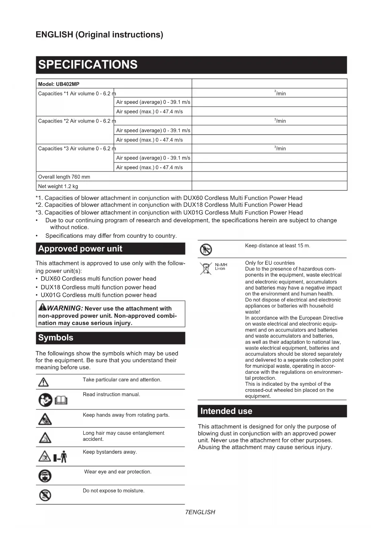
| Air Volume | 0 – 6.2 m³/min |
| Air Speed (average) | 0 – 39.1 m/s |
| Air Speed (max.) | 0 – 47.4 m/s |
| Compatible Power Units | DUX60, DUX18, UX01G (cordless multi-function power heads) |
| Power Source | Via power unit (Makita Li-ion battery) |
| Intended Use | Blowing dust and debris |
| End Nozzle | Included, with length adjustment |
| Optional Accessories | Nozzle extension, flat nozzle, gutter nozzle kit |
| Attachment | By clamp lever on power unit |
| Carrying Strap | Use the provided strap (except UX01G with BL4080F) |
| Maintenance | Clean with damp cloth, lubricate motor shaft every 30 h |
| Safety | Safety glasses, hearing protection, fitted clothing, safety distance 15 m |
| Standards | CE, EN 60335-1, EN 50636-2-100 |
| Warranty | Consult the power unit manual |
Frequently Asked Questions - UB402MP MAKITA
User questions about UB402MP MAKITA
0 question about this device. Answer the ones you know or ask your own.
Ask a new question about this device
Download the instructions for your Blower accessory in PDF format for free! Find your manual UB402MP - MAKITA and take your electronic device back in hand. On this page are published all the documents necessary for the use of your device. UB402MP by MAKITA.
USER MANUAL UB402MP MAKITA
natural_image
Technical diagram of a mechanical device with labeled component '1' and directional arrow (no text or symbols beyond label)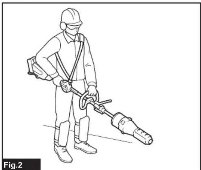
natural_image
Line drawing of a person in protective gear using a handheld tool (no text or symbols)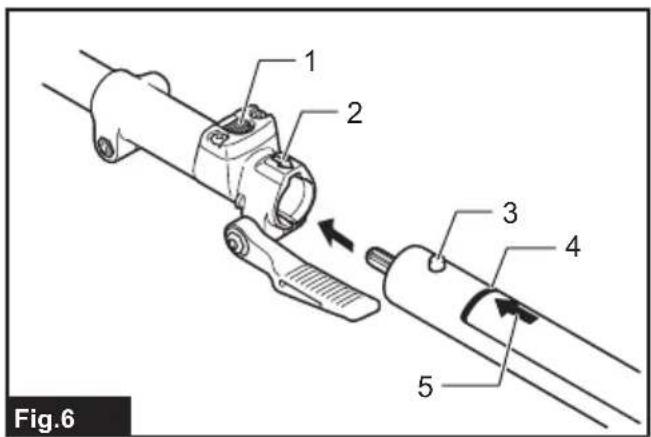
natural_image
Mechanical assembly diagram showing a lever mechanism with motion arrows (no text or symbols)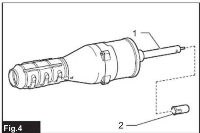
flowchart
graph TD
    A["Top Component"] --> B["Bottom Component"]
    B --> C{Downward Arrow}
    C --> D["Bottom Component with Internal Control Valve"]
    D --> E["Bottom Component with Internal Motor"]
    E --> F["Bottom Component with Internal Motor"]
    F --> G["Bottom Component with Internal Motor"]
Fig.10
natural_image
Diagram showing a pipe fitting being modified, with no text or symbols present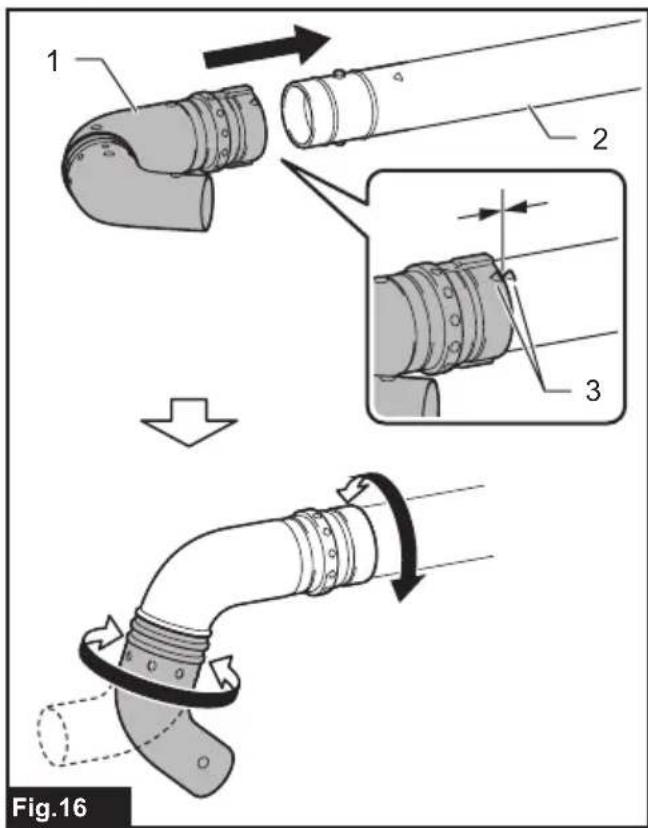
natural_image
Line drawing of a worker in protective gear using a handheld tool (no text or symbols)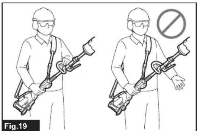
natural_image
Illustration of two workers in protective gear holding a handheld device, with no visible text or symbols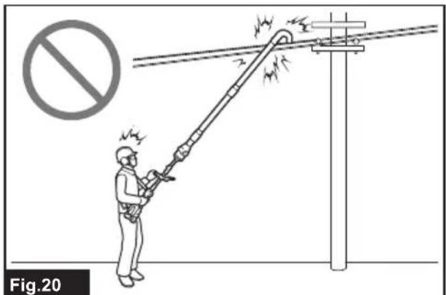
natural_image
Illustration of a worker using a long pole to lift a rope, with no visible text or symbols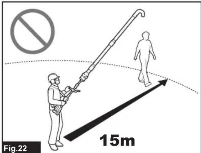
natural_image
Line drawing of a worker spraying water on a building facade, no text or symbols present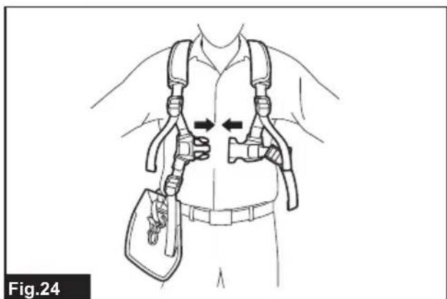
natural_image
Line drawing of a person wearing a full-body harness and belt, with arrows indicating movement or force direction (no text or symbols)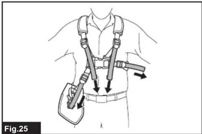
natural_image
Illustration of a person wearing a full-body medical harness with straps and a belt, showing posture changes (no text or symbols)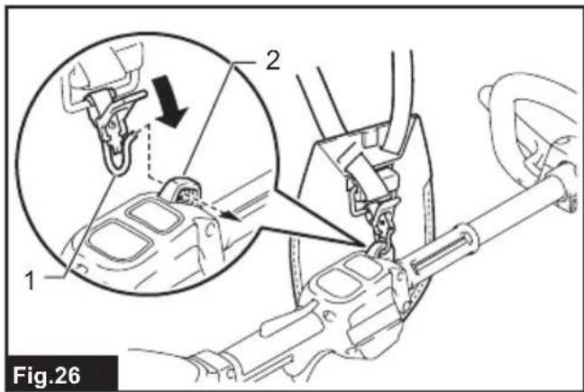
natural_image
Line drawing of a hand gripping a car wheel, labeled Fig.28 (no text or symbols on the diagram itself)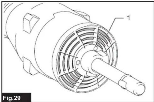
natural_image
Technical line drawing of a mechanical component with labeled parts (no text or symbols beyond label)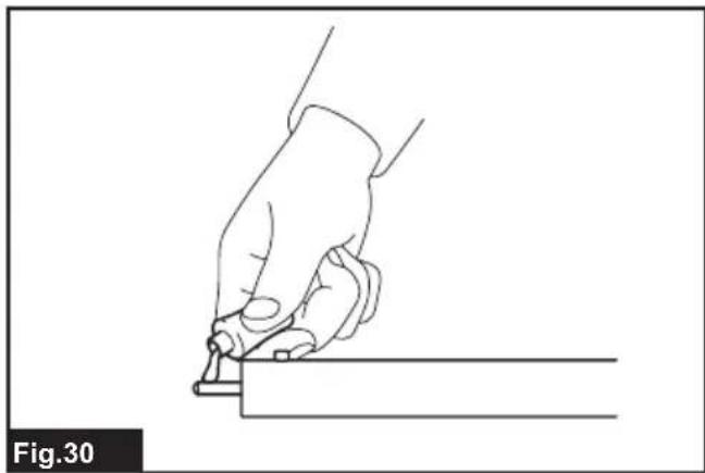
natural_image
Line drawing of a hand using a tool to cut or mark a rectangular object, labeled Fig.30 (no text or symbols on the diagram itself)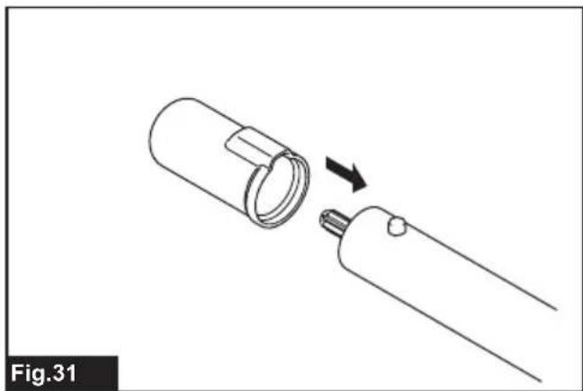
natural_image
Diagram of a mechanical component with a cylindrical part being inserted, showing a directional arrow (no text or symbols)SPECIFICATIONS
| Model: UB402MP | ||
| Capacities *1 Air volume 0 - 6.2 m | ^3 /min | |
| Air speed (average) 0 - 39.1 m/s | ||
| Air speed (max.) 0 - 47.4 m/s | ||
| Capacities *2 Air volume 0 - 6.2 m | ^3 /min | |
| Air speed (average) 0 - 39.1 m/s | ||
| Air speed (max.) 0 - 47.4 m/s | ||
| Capacities *3 Air volume 0 - 6.2 m | ^3 /min | |
| Air speed (average) 0 - 39.1 m/s | ||
| Air speed (max.) 0 - 47.4 m/s | ||
| Overall length 760 mm | ||
| Net weight 1.2 kg | ||
*1. Capacities of blower attachment in conjunction with DUX60 Cordless Multi Function Power Head
*2. Capacities of blower attachment in conjunction with DUX18 Cordless Multi Function Power Head
*3. Capacities of blower attachment in conjunction with UX01G Cordless Multi Function Power Head
- Due to our continuing program of research and development, the specifications herein are subject to change without notice.
• Specifications may differ from country to country.
Approved power unit
This attachment is approved to use only with the following power unit(s):
- DUX60 Cordless multi function power head
• DUX18 Cordless multi function power head - UX01G Cordless multi function power head
WARNING: Never use the attachment with non-approved power unit. Non-approved combination may cause serious injury.
Symbols
The followings show the symbols which may be used for the equipment. Be sure that you understand their meaning before use.

Take particular care and attention.


Read instruction manual.

Keep hands away from rotating parts.


Long hair may cause entanglement accident.

Keep bystanders away.
Wear eye and ear protection.
Do not expose to moisture.

Keep distance at least 15 m.

Ni-MH Li-ion
Only for EU countries
Due to the presence of hazardous components in the equipment, waste electrical and electronic equipment, accumulators and batteries may have a negative impact on the environment and human health. Do not dispose of electrical and electronic appliances or batteries with household waste!
In accordance with the European Directive on waste electrical and electronic equipment and on accumulators and batteries and waste accumulators and batteries, as well as their adaptation to national law, waste electrical equipment, batteries and accumulators should be stored separately and delivered to a separate collection point for municipal waste, operating in accordance with the regulations on environmental protection.
This is indicated by the symbol of the crossed-out wheeled bin placed on the equipment.
Intended use
This attachment is designed for only the purpose of blowing dust in conjunction with an approved power unit. Never use the attachment for other purposes.
Abusing the attachment may cause serious injury.
EC Declaration of Conformity
For European countries only
We as the manufacturers: Makita Europe N.V., Business address: Jan-Baptist Vinkstraat 2 3070 Kortenberg BELGIUM. Authorize Hiroshi Tsujimura for the compilation of the technical file and declare under our sole responsibility that the product(s); Designation: Blower Attachment. Designation of Type(s): UB402MP.
Fulfills all the relevant provisions of 2006/42/EC and also fulfills all the relevant provisions of the following EC/EU Directives: 2000/14/EC and are manufactured in accordance with the following Harmonised Standards: EN 60335-1:2012+A11:2014+A13:2017+A1:2019+A14:2019+A2:2019, EN 50636-2-100:2014.
Place and date of declaration: Kortenberg, Belgium. 31.10.2022
Responsible person: Hiroshi Tsujimura, Director - Makita Europe N.V.
Declaration of Conformity (For UK)
For UK only
We as the manufacturers: Makita Europe N.V., Business address: Jan-Baptist Vinkstraat 2 3070 Kortenberg BELGIUM. Authorize Hiroshi Tsujimura for the compilation of the technical file and declare under our sole responsibility that the product(s); Designation: Blower Attachment. Designation of Type(s): UB402MP.
Fulfills all the relevant provisions of S.I. 2008/1597 (as amended) and also fulfills all the relevant provisions of the following UK Regulations: S.I. 2001/1701 (as amended) and are manufactured in accordance with the following Designated Standards: EN 15503:2009+A1:2013+A2:2015, EN 50636-2-100:2014.
Place and date of declaration: Kortenberg, Belgium. 31.10.2022
Responsible person: Hiroshi Tsujimura, Director - Makita Europe N.V.
Importer: Makita (UK) Limited, Michigan Drive, Tongwell, Milton Keynes, Buckinghamshire, MK15 8JD, UK
SAFETY WARNINGS
Blower Safety Instructions
WARNING: Read all safety warnings, instructions, illustrations and specifications provided with this machine as well as the instruction manual of the power unit before using. Failure to follow all instructions listed below may result in electric shock, fire, and/or serious injury to the operator and/or bystanders.
Save all warnings and instructions for future reference.
The term “blower” and “machine” in the warnings and precautions refer to the combination of the attachment and the power unit.
Training
- Read the instructions carefully. Be familiar with the controls and the correct use of the blower.
- Never allow children, persons with reduced physical, sensory or mental capabilities or lack of experience and knowledge or people unfamiliar with these instructions to use the blower. Local regulations may restrict the age of the operator.
- Never operate the blower while people, especially children, or pets are nearby.
- Keep in mind that the operator or user is responsible for accidents or hazards occurring to other people or their property.
Preparation
- Always wear substantial footwear and long trousers while operating the blower.
- Do not wear loose clothing or jewellery that can be drawn into the air inlet. Keep long hair away from the air inlets.
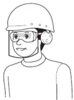
- Always wear protective goggles to protect your eyes from injury when using power tools. The goggles must comply with ANSI Z87.1 in the USA, EN 166 in Europe, or AS/NZS 1336 in Australia/New Zealand. In Australia/New Zealand, it is legally required to wear a face shield to protect your face, too.
natural_image
Line drawing of a person wearing a helmet and safety goggles (no text or symbols)It is an employer's responsibility to enforce the use of appropriate safety protective equipments by the tool operators and by other persons in the immediate working area.
- To prevent dust irritation the wearing of a face mask is recommended.
- While operating the machine, always wear non-slip and protective footwear. Non-skid, closed-toed safety boots and shoes will reduce the risk of injury.
- Wear ear protection, such as ear muffs. Exposure to noise can cause hearing loss.
Operation
- Clear the area of children, bystanders, and pets. At a minimum, keep all children, bystanders, and pets outside a 15 m radius; outside the 15 m zone, there is still a risk of injury from thrown objects. Bystanders should be encouraged to wear eye protection. If you are approached, stop the machine.
▶ Fig.1
- Switch off the blower and remove the battery cartridge, and make sure that all moving parts have come to a complete stop
• whenever you leave the blower.
• before clearing blockages.
- before checking, cleaning or working on the blower.
- if the blower starts to vibrate abnormally.
- Operate the blower only in daylight or in good artificial light.
- Do not overreach and keep proper balance and footing at all times.
- Always be sure of your footing on slopes.
- Walk, never run.
- Keep all cooling air inlets clear of debris.
- Never blow debris in the direction of bystanders.
- Operate the blower in a recommended position and on a firm surface.
- Do not operate the blower at high places.
- Never point the nozzle at anyone in the vicinity when using the blower.
- Never block suction inlet and/or blower outlet.
- Be careful not to block suction inlet or blower outlet with dust or dirt when operating in dusty area.
- Do not use nozzles other than the nozzles provided by Makita.
- Do not use the blower to inflate balls, rubber boat or the similar.
- Do not operate the blower near open window, etc.
- Operating the blower only at reasonable hours is recommended - not early in the morning or late at night when people might be disturbed.
- Using rakes and brooms to loosen debris before blowing is recommended.
- Before blowing, slightly dampen surfaces in dusty conditions or use water mist sprayer if necessary.
-
Adjust the length of the blower nozzle so that the air stream can work close to the ground.
-
If the blower strikes any foreign objects or should start making any unusual noise or vibration, immediately switch off the blower to stop it. Remove the battery cartridge, and inspect the blower for damage before restarting and operating the blower. If the blower is damaged, ask Makita Authorized Service Centers for repair.
- Do not insert fingers or other objects into suction inlet or blower outlet.
- Prevent unintentional starting. Ensure the switch is in the off-position before inserting battery cartridge, picking up or carrying the blower. Carrying the blower with your finger on the switch or energizing the blower that has the switch on invites accidents.
- Never blow dangerous materials, such as nails, fragments of glass, or blades.
- Do not operate the blower near flammable materials.
- Avoid operating the blower for a long time in low temperature environment.
- Before assembling or adjusting the machine, switch off the motor and remove the battery cartridge.
- Wear the personal protective equipments before starting the motor.
- Before starting the motor, inspect the machine for damages, loose screws/nuts or improper assembly. Check all control levers and switches for easy action. Clean and dry the handles.
- Never attempt to start the motor if the machine is damaged or not fully assembled.
- Adjust the shoulder harness and hand grip to suit the operator's body size.
- During operation, use the shoulder harness. Keep the machine on your right side firmly.
▶ Fig.2
- Hold the front handle with the left hand and the rear grip with the right hand, no matter you are right-hander or left-hander. Wrap your fingers and thumbs around the handles.
- Never attempt to operate the machine with one hand. Loss of control may result in an injury.
- If the machine gets heavy impact or fall, check the condition before continuing work. Check the controls and safety devices for malfunction. If there is any damage or doubt, ask our authorized service center for the inspection and repair.
- Follow the instruction manual of the power unit for proper use of the power unit.
- Refer to the instruction manual of the power unit for how to start and control the machine.
- During operation, never stand on an unstable or slippery surface or a steep slope. During the cold season, beware of ice and snow and always ensure secure footing.
- Do not use the machine in bad weather where visibility is limited. Failure to do so may cause fall or incorrect operation due to low visibility.
- Do not use the machine when there is a risk of lightning.
Transportation
- Stop the motor during transportation.
Otherwise unintentional start-up may cause injury.
Vibration
- Exposing to excessive vibration injures blood vessels or nervous system of the operator and causes the following symptoms in the fingers, hands or wrists: "Falling asleep" (numbness), tingling, pain, stabbing sensation, alteration of skin color or of the skin. If any of these symptoms occur, see a physician. To reduce the risk of "white finger disease", keep your hands warm during operation and well maintain the machine and accessories.
Maintenance and storage
-
Keep all nuts, bolts and screws tight to be sure the blower is in safe working condition.
-
If the parts are worn or damaged, replace them with parts provided by Makita.
-
Store the blower in a dry place out of the reach of children.
-
When you stop the blower for inspection, servicing, storage, or changing accessory, switch off the blower and make sure that all moving parts come to a complete stop, and remove the battery cartridge. Cool down the blower before making any work on the blower. Maintain the blower with care and keep it clean.
-
Always cool down the blower before storing.
-
Do not expose the blower to rain. Store the blower indoors.
-
When you lift the blower, be sure to bend your knees and be careful not to hurt your back.
-
Always clean dust and dirt off the equipment. Never use gasoline, benzine, thinner, alcohol or the like for the purpose. Discoloration, deformation or cracks of the plastic components may result.
-
Do not attempt any maintenance or repair not described in this instruction manual or the instruction manual of the power unit. Ask our authorized service center for such work.
-
Follow instructions for lubricating and changing accessories.
-
Always use the genuine spare parts and accessories only. Using parts or accessories supplied by a third party may result in the equipment breakdown, property damage and/or serious injury.
-
Request our authorized service center to inspect and maintain the machine at regular interval.
-
Before storing the machine, perform full cleaning and maintenance. Remove the battery cartridge.
-
Do not prop the equipment against something, such as a wall. Otherwise it may fall suddenly and cause an injury.
Battery tool use and care
-
Recharge only with the charger specified by the manufacturer. A charger that is suitable for one type of battery pack may create a risk of fire when used with another battery pack.
-
Use power tools only with specifically designated battery packs. Use of any other battery packs may create a risk of injury and fire.
-
When battery pack is not in use, keep it away from other metal objects, like paper clips, coins, keys, nails, screws or other small metal objects, that can make a connection from one terminal to another. Shorting the battery terminals together may cause burns or a fire.
- Under abusive conditions, liquid may be ejected from the battery; avoid contact. If contact accidentally occurs, flush with water. If liquid contacts eyes, additionally seek medical help. Liquid ejected from the battery may cause irritation or burns.
- Do not use a battery pack or tool that is damaged or modified. Damaged or modified batteries may exhibit unpredictable behaviour resulting in fire, explosion or risk of injury.
- Do not expose a battery pack or tool to fire or excessive temperature. Exposure to fire or temperature above 130 °C may cause explosion.
- Follow all charging instructions and do not charge the battery pack or tool outside the temperature range specified in the instructions. Charging improperly or at temperatures outside the specified range may damage the battery and increase the risk of fire.
Electrical and battery safety
- Do not dispose of the battery(ies) in a fire. The cell may explode. Check with local codes for possible special disposal instructions.
- Do not open or mutilate the battery(ies). Released electrolyte is corrosive and may cause damage to the eyes or skin. It may be toxic if swallowed.
- Do not charge battery in rain, or in wet locations.
- Do not charge the battery outdoors.
- Do not handle charger, including charger plug, and charger terminals with wet hands.
Service
- Have your power tool serviced by a qualified repair person using only identical replacement parts. This will ensure that the safety of the power tool is maintained.
- Never service damaged battery packs. Service of battery packs should only be performed by the manufacturer or authorized service providers.
SAVE THESE INSTRUCTIONS.
WARNING: DO NOT let comfort or familiarity with product (gained from repeated use) replace strict adherence to safety rules for the subject product.
MISUSE or failure to follow the safety rules stated in this instruction manual may cause serious personal injury.
PARTS DESCRIPTION
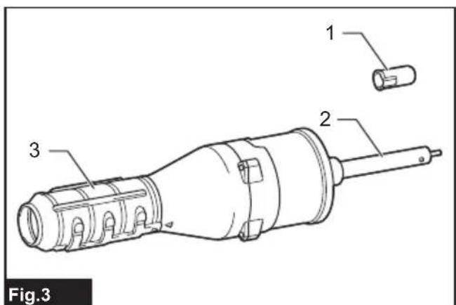
▶ Fig.3: 1. Cap 2. Pipe 3. End nozzle
ASSEMBLY
WARNING: Before assembling or adjusting the equipment, switch off the motor and remove the battery cartridge. Otherwise, the fans may move and result in an injury.
WARNING: When assembling or adjusting the equipment, always put it down. Assembling or adjusting the equipment in an upright position may result in serious injury.
WARNING: Follow the warnings and precautions in the chapter "SAFETY WARNINGS" and the instruction manual of the power unit.
Mounting the attachment pipe
⚠️CAUTION: Always check that the attachment pipe is secured after installation. Improper installation may cause the attachment falling off from the power unit and cause personal injury.
Mount the attachment pipe to the power unit.
- Remove the cap from the end of the pipe.
▶ Fig.4: 1. Pipe 2. Cap
NOTICE: Do not dispose of the cap since the cap is necessary for storing the attachment.
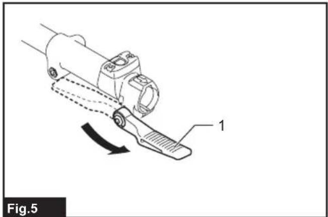
- Turn the lever toward the attachment.
▶ Fig.5: 1. Lever - Align the pin with the arrow mark on the power unit. Insert the pipe until the release button pops up.
Make sure that the position line is on the tip of the arrow mark on the power unit, and the arrow mark on the power unit and the arrow mark on the pipe are facing each other.
▶ Fig.6: 1. Release button 2. Arrow mark on the power unit 3. Pin 4. Position line 5. Arrow mark on the pipe
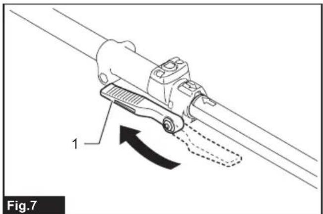
- Turn the lever toward the power unit.
▶ Fig.7: 1. Lever
Make sure that the surface of the lever is parallel to the pipe.
NOTICE: Do not tighten the lever without the attachment pipe inserted. Otherwise the lever may tighten the entrance of the drive shaft too much and damage it.
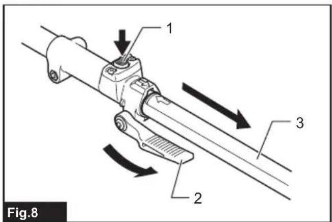
To remove the pipe, turn the lever toward the attachment and pull the pipe out while pressing down the release button.
▶ Fig.8: 1. Release button 2. Lever 3. Pipe
Installing the end nozzle
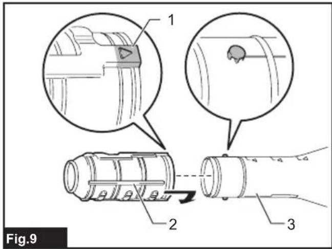
Align the protrusion on the blower pipe with the groove on the end nozzle, then attach the end nozzle to the blower pipe, and then turn the end nozzle to lock it into place.
▶ Fig.9: 1. Triangle mark 2. End nozzle 3. Blower pipe
To remove the end nozzle, perform the installation procedure in reverse.
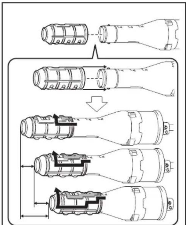
NOTE: The length of the nozzle can be changed by moving the nozzle as shown in the figure.
▶ Fig.10
Installing the flat nozzle or extension nozzle
Optional accessory
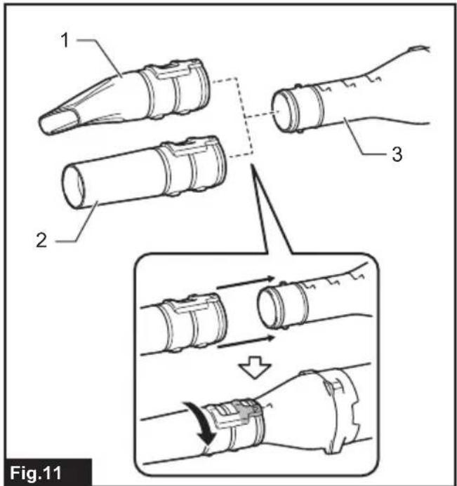
- Remove the end nozzle from the attachment.
- Attach the flat nozzle or extension nozzle to the attachment, and then turn it to lock it into place.
▶ Fig.11: 1. Flat nozzle 2. Extension nozzle
- Attachment
Installing the gutter nozzle set
Optional accessory
- Remove the end nozzle, extension nozzle, or flat nozzle from the attachment.
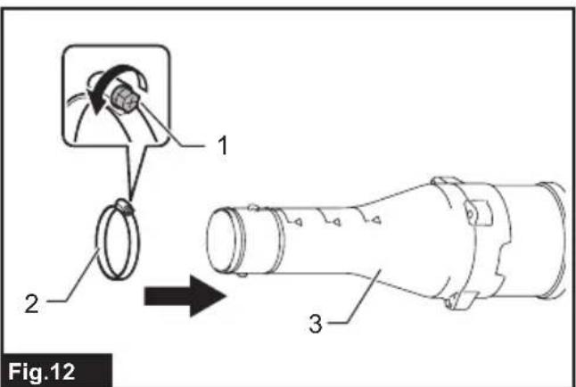
- Loosen the screw on the small hose clamp, and pass the hose clamp through the attachment.
▶ Fig.12: 1. Screw 2. Hose clamp (small)
-
Attachment
-
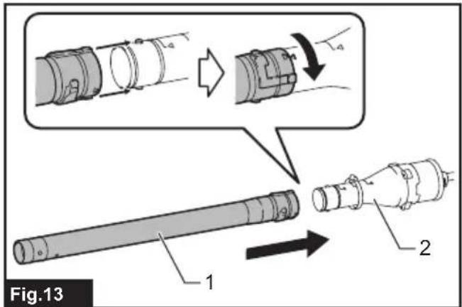
Connect the extension pipe to the attachment.
Align the groove on the extension pipe with the protrusion on the attachment, and then slide the extension pipe along its groove so that the triangle markings face each other.
▶ Fig.13: 1. Extension pipe 2. Attachment
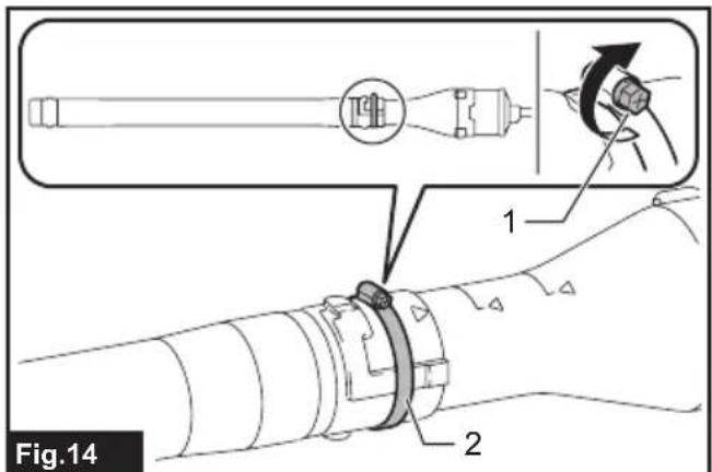
- Place the hose clamp onto the groove as illustrated and tighten the screw.
▶ Fig.14: 1. Screw 2. Hose clamp - According to the working height, connect the rest of extension pipes to the extension pipe which has already been attached.
CAUTION: When using the gutter nozzle set in conjunction with a multi function power head and blower attachment, do not use three or more extension pipes. It may cause imbalance and result in injury.
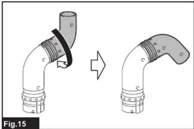
- Turn the outlet of the end nozzle as shown in the figure.
▶ Fig.15 - Connect the end nozzle to the extension pipe. When connecting, align the triangle marking on the end nozzle and the extension pipe, and then push the end nozzle until it clicks. After that, rotate the end nozzle to a suitable position for your work.
▶ Fig.16: 1. End nozzle 2. Extension pipe 3. Triangle marking
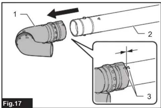
When removing the end nozzle, align the triangle markings on the end nozzle and extension pipe, and then pull out the end nozzle from the extension pipe.
▶ Fig.17: 1. End nozzle 2. Extension pipe 3. Triangle marking
OPERATION
WARNING: Follow the warnings and precautions in the chapter "SAFETY WARNINGS" and the instruction manual of the power unit.
WARNING: Adjust the hanger position and shoulder harness to your comfortable position before operating.
Blower operation
⚠CAUTION: Do not place the machine on the ground while it is switched on. Sand or dust may enter from suction inlet and cause a malfunction or personal injury.
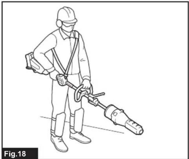
Hold the machine firmly with both hands and perform the blowing operation by moving it around slowly. When blowing around building, big stone or vehicle, direct the nozzle away from them. When performing an operation in a corner, start from the corner and then move to wide area.
Adjust the air speed with the switch trigger of the power unit according to the environment or conditions of your usage.
▶ Fig.18
Using the gutter nozzle set
⚠️CAUTION: When using the gutter nozzle set, do not hold the blower with single hand but with both hands.
▶ Fig.19
⚠️CAUTION: Do not use the gutter nozzle set near electric wires.
▶ Fig.20
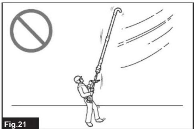
⚠️CAUTION: Do not use the gutter nozzle set on windy day.
▶ Fig.21
⚠CAUTION: When using the gutter nozzle set, keep other people or animal more than 15 m away from the blower.
▶ Fig.22
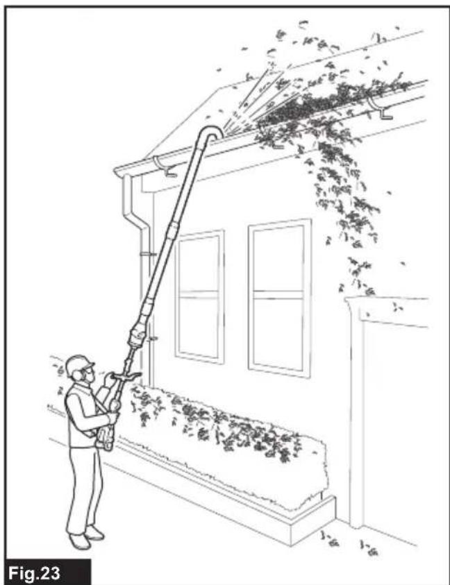
Hold the blower upright by grabbing the handle of the blower. Place the outlet of the blower on the gutter and then turn on the blower.
▶ Fig.23
For UX01G users
NOTICE: When using the gutter nozzle set, if you use UX01G as the power unit and install BL4080F to UX01G, do not use the shoulder harness included in the power unit package, but use the recommended shoulder harness shown below. For the recommended shoulder harness, ask Makita Authorized Service Centers.
Attaching the shoulder harness
CAUTION: Always use the shoulder harness attached to the power unit. Before operation, adjust the shoulder harness according to the user size to prevent fatigue.
CAUTION: Before operation, make sure that the shoulder harness is properly attached to the hanger on the power unit.
⚠️ CAUTION: Before operation, make sure that the buckle of the shoulder harness is fastened firmly.
CAUTION: Always use the shoulder harness shown below. Do not use other shoulder harnesses.
- Put on the shoulder harness and fasten the buckle.
▶ Fig.24: 1. Buckle
NOTE: When removing the shoulder harness, unlock the buckle and remove the shoulder harness.
- Adjust the shoulder harness to a comfortable working position.
▶ Fig.25 - Clasp the hook on the shoulder harness to the hanger of the power unit.
▶ Fig.26: 1. Hook 2. Hanger
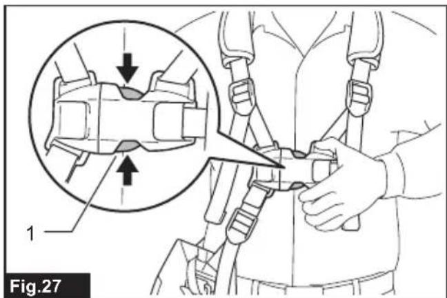
The shoulder harness features a means of quick release. Simply squeeze the sides of the buckle to release the shoulder harness.
▶ Fig.27: 1. Buckle
MAINTENANCE
WARNING: Before inspecting or maintaining the equipment, switch off the motor and remove the battery cartridge. Otherwise, the fans may move and result in serious injury.
WARNING: When inspecting or maintaining the equipment, always put it down. Assembling or adjusting the equipment in an upright position may result in serious injury.
WARNING: Follow the warnings and precautions in the chapter "SAFETY WARNINGS" and the instruction manual of the power unit.
NOTICE: Never use gasoline, benzine, thinner, alcohol or the like. Discoloration, deformation or cracks may result.
To maintain product SAFETY and RELIABILITY, repairs, any other maintenance or adjustment should be performed by Makita Authorized or Factory Service Centers, always using Makita replacement parts.
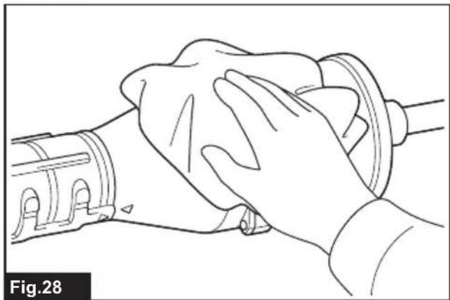
Cleaning the machine
Clean the machine by wiping off dust with a dry cloth or one dipped in soapy water and wrung out.
▶ Fig.28
Remove dust or dirt from the suction inlet at the rear of the attachment.
▶ Fig.29: 1. Suction inlet
Overall inspection
Check for damaged parts. Ask our authorized service center to replace them if necessary.
Lubricating moving parts
NOTICE: Follow the instruction of the frequency and amount of grease supplied. Otherwise insufficient lubrication may damage moving parts.
Drive axle:
Apply grease (Makita grease N No.2 or equivalent) every 30 hours of operation.
▶ Fig.30
NOTE: Genuine Makita grease may be purchased from your local Makita dealer.
Storage
When storing the attachment separated from the power unit, put the cap onto the end of the pipe.
▶ Fig.31
Interval of inspection and maintenance
| Operating hour Before | Operation | Daily (10 hours) 30 hours | |
| Whole unit Visually inspect for damaged parts | √ | - | |
| Drive axle Supply grease -- | |||
| Power unit Refer to the instruction manual of the power unit | |||
TROUBLESHOOTING
Before asking for repairs, conduct your own inspection first. If you find a problem that is not explained in the manual, do not attempt to disassemble the machine. Instead, ask Makita Authorized Service Centers, always using Makita replacement parts for repairs.
| State of abnormality Probable cause | (malfunction) Remedy | |
| Motor does not start. - Refer to the instruction manual of the power unit. | ||
| Motor stops soon. - Refer to the instruction manual of the power unit. | ||
| Motor speed does not increase. - Refer to the instruction manual of the power unit. | ||
| Fans do not rotate.⇒ Stop the motor immediately. | The pipes of the power unit and the attachment are not connected properly. | Connect the pipes in the correct way. |
| Abnormal drive system Contact an authorized service center for repairs. | ||
| Power unit vibrates abnormally.⇒ Stop the motor immediately. | Abnormal drive system Contact an authorized service center for repairs. | |
| Fans continue to rotate even if the switch trigger is released.⇒ Stop the motor immediately. | The power unit does not work properly. | Contact an authorized service center for repairs. |
OPTIONAL ACCESSORIES
CAUTION: These accessories or attachments are recommended for use with your Makita machine specified in this manual. The use of any other accessories or attachments might present a risk of injury to persons. Only use accessory or attachment for its stated purpose.
NOTE: Some items in the list may be included in the product package as standard accessories. They may differ from country to country.
If you need any assistance for more details regarding these accessories, ask your local Makita Service Center.
- Extension nozzle
- Flat nozzle
- Gutter nozzle set
• Makita genuine battery and charger
SPÉCIFICATIONS
natural_image
Line drawing of a person wearing a helmet and safety goggles (no text or symbols)natural_image
Line drawing of a person wearing a hard hat and safety goggles (no text or symbols)▶ Abb.24: 1. Schnalle
natural_image
Line drawing of a person wearing a hard hat and safety goggles (no text or symbols)VEILIGHEIDSWAAR- SCHUWINGEN
natural_image
Line drawing of a person wearing a hard hat and safety goggles (no text or symbols)▶ Fig.29: 1. Aanzuigopening
Algehele inspectie
OPTIONELE ACCESSOIRES
Persona responsible: Hiroshi Tsujimura, Director - Makita Europe N.V.
natural_image
Line drawing of a person wearing a helmet and safety goggles (no text or symbols)natural_image
Line drawing of a person wearing a helmet and safety goggles (no text or symbols)▶ Fig.3: 1. Tampa 2. Tubo 3. Bocal final
MONTAGEM
natural_image
Line drawing of a person wearing a helmet and safety goggles (no text or symbols)▶ Fig.29: 1. Sugeåbning
natural_image
Line drawing of a person wearing a helmet and safety goggles (no text or symbols)natural_image
Line drawing of a person wearing a hard hat and safety goggles (no text or symbols)natural_image
Line drawing of a person wearing a helmet and safety goggles (no text or symbols)natural_image
Line drawing of a person wearing a helmet and safety goggles (no text or symbols)▶ Fig.29: 1. Sugeinngang
Generell inspeksjon
natural_image
Line drawing of a person wearing a hard hat and safety goggles (no text or symbols)natural_image
Line drawing of a person wearing a hard hat and safety goggles (no text or symbols)natural_image
Line drawing of a person wearing a helmet and safety goggles (no text or symbols)natural_image
Line drawing of a person wearing a helmet and safety goggles (no text or symbols)▶ Joon.26: 1. Konks 2. Riputi
▶ Joon.27: 1. Pannal
HOOLDUS
natural_image
Line drawing of a person wearing a helmet and safety goggles (no text or symbols)natural_image
Line drawing of a person wearing a hard hat and safety goggles (no text or symbols)natural_image
Line drawing of a person wearing a hard hat and safety goggles (no text or symbols)TIETO POKYNY USCHOVAJTE.
natural_image
Line drawing of a person wearing a helmet and safety goggles (no text or symbols)TYTO POKYNY USCHOVEJTE.
▶ Obr.26: 1. Háček 2. Závěs
VOLITELNÉ PŘÍSLUŠENSTVÍ
natural_image
Line drawing of a person wearing a hard hat and safety goggles (no text or symbols)natural_image
Line drawing of a person wearing a helmet and safety goggles (no text or symbols)natural_image
Line drawing of a person wearing a hard hat and safety goggles (no text or symbols)natural_image
Line drawing of a person wearing a helmet and safety goggles (no text or symbols)natural_image
Line drawing of a person wearing a helmet and safety goggles (no text or symbols)natural_image
Line drawing of a person wearing a helmet and safety goggles (no text or symbols)natural_image
Line drawing of a person wearing a hard hat and safety goggles (no text or symbols)natural_image
Line drawing of a person wearing a hard hat and safety goggles (no text or symbols)natural_image
Line drawing of a person wearing a helmet and safety goggles (no text or symbols)natural_image
Line drawing of a person wearing a helmet and safety goggles (no text or symbols)natural_image
Line drawing of a person wearing a hard hat and safety goggles (no text or symbols)natural_image
Line drawing of a person wearing a hard hat and safety goggles (no text or symbols)▶ 图片14: 1. 螺丝 2. 软管夹