UB403MP - Blower accessory MAKITA - Free user manual and instructions
Find the device manual for free UB403MP MAKITA in PDF.

User questions about UB403MP MAKITA
0 question about this device. Answer the ones you know or ask your own.
Ask a new question about this device
Download the instructions for your Blower accessory in PDF format for free! Find your manual UB403MP - MAKITA and take your electronic device back in hand. On this page are published all the documents necessary for the use of your device. UB403MP by MAKITA.
USER MANUAL UB403MP MAKITA
Fig.1
natural_image
Technical diagram of a mechanical clamp or lever mechanism with labeled component '1' and directional arrow (no text or symbols beyond label)Fig.5
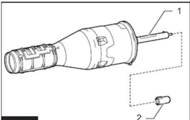
Fig.2
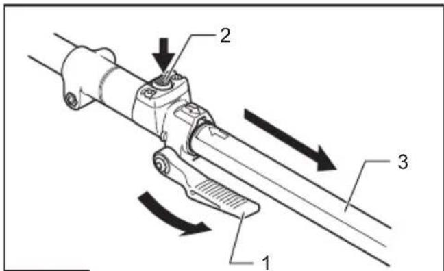
Fig.6
natural_image
Technical line drawing of a mechanical device with a lever and adjustment arrow (no text or symbols)Fig.3
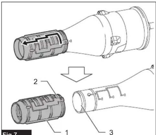
Fig.7
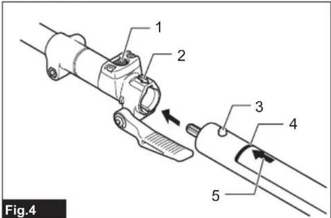
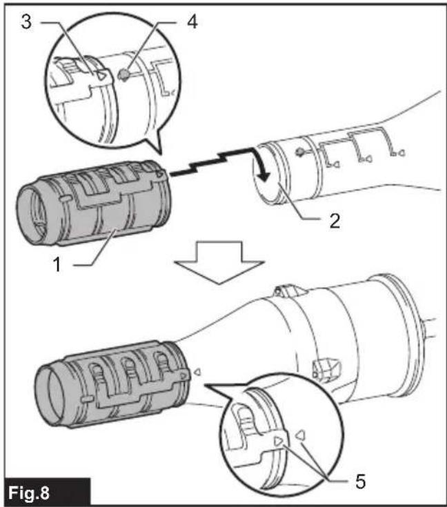
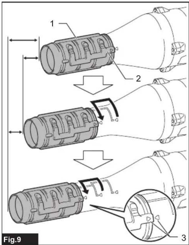
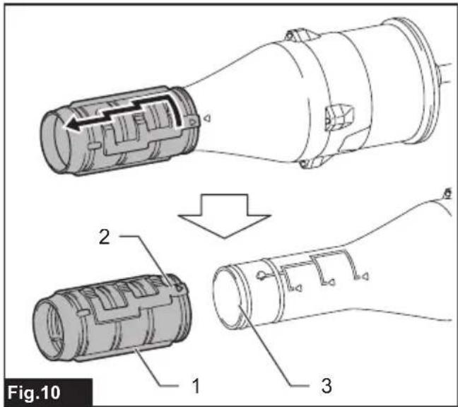
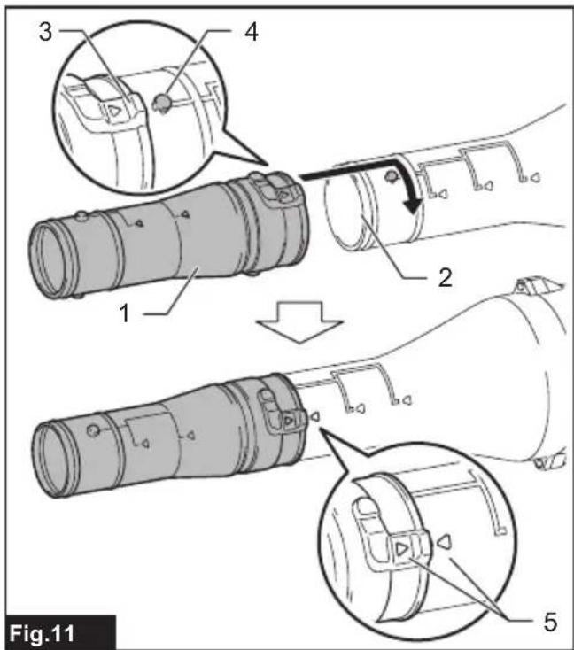
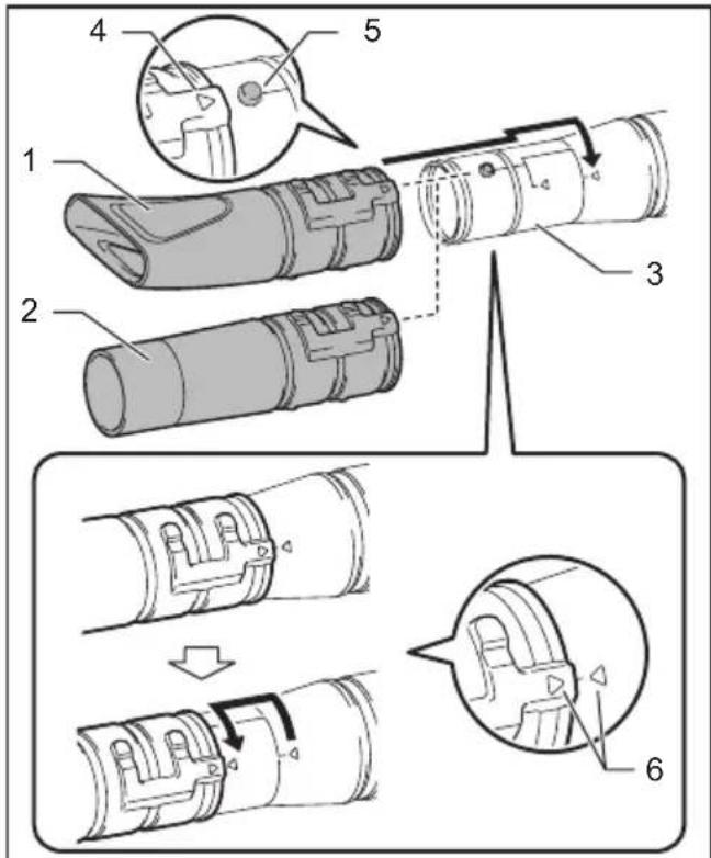
Fig.12
natural_image
Line drawing of a person in protective gear using a handheld tool (no text or symbols)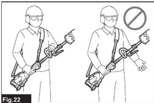
natural_image
Illustration of two workers holding a metal detector with a prohibition symbol (no text or labels)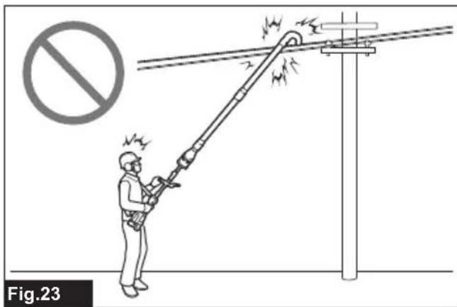
natural_image
Illustration of a worker using a power line tool to clean electrical lines, with no visible text or symbols.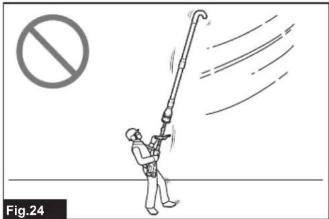
natural_image
Illustration of a worker using a long pole to lift a pipe with motion lines, no text or symbols present
natural_image
Line drawing of a hand gripping a device, no text or symbols present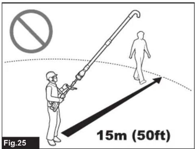
natural_image
Technical line drawing of a mechanical component with labeled part '1', no readable text or symbols beyond label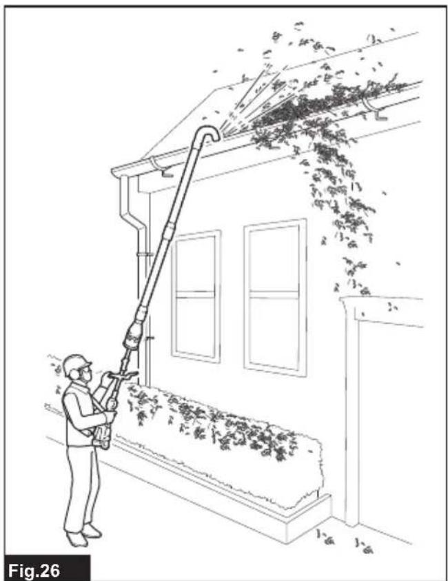
natural_image
Line drawing of a person using a tool to clean or exhaust leafy material from a building (no text or symbols)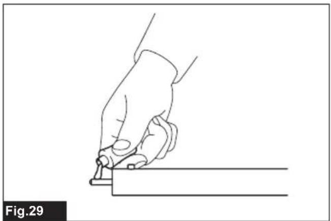
natural_image
Line drawing of a hand holding a tool, poised to write on a line (no text or symbols present)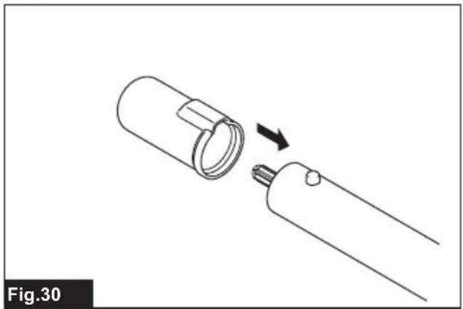
natural_image
Diagram of a mechanical component being inserted into a cylindrical housing, showing a force direction (no text or symbols)SPECIFICATIONS
| Model: UB403MP | ||
| Capacities *1 Air | volume 0 - 14.9 m | ^3/min |
| Air speed (average) 0 - 49.3 m/s | ||
| Air speed (max.) 0 - 59.3 m/s | ||
| Capacities *2 Air | volume 0 - 12.9 m | ^3/min |
| Air speed (average) 0 - 42.6 m/s | ||
| Air speed (max.) 0 - 50.8 m/s | ||
| Capacities *3 Air | volume 0 - 16.8 m | ^3/min |
| Air speed (average) 0 - 55.4 m/s | ||
| Air speed (max.) 0 - 66.5 m/s | ||
| Overall length 740 - 840 mm | ||
| Net weight 1.5 kg | ||
*1. Capacities of blower attachment in conjunction with DUX60 Cordless Multi Function Power Head (with battery BL1860B x 2)
*2. Capacities of blower attachment in conjunction with DUX18 Cordless Multi Function Power Head (with battery BL1860B)
*3. Capacities of blower attachment in conjunction with UX01G Cordless Multi Function Power Head (with battery BL4040)
- Due to our continuing program of research and development, the specifications herein are subject to change without notice.
• Specifications may differ from country to country.
Approved power unit
This attachment is approved to use only with the following power unit(s):
- DUX60 Cordless multi function power head
- DUX18 Cordless multi function power head
- UX01G Cordless multi function power head

WARNING: Never use the attachment with n-approved power unit. Non-approved combination may cause serious injury.
Symbols
The followings show the symbols which may be used for the equipment. Be sure that you understand their meaning before use.

Take particular care and attention.


Read instruction manual.

Keep hands away from rotating parts.


Ni-MH Li-ion

Wear eye and ear protection.
Do not expose to moisture.
Only for EU countries
Due to the presence of hazardous components in the equipment, waste electrical and electronic equipment, accumulators and batteries may have a negative impact on the environment and human health. Do not dispose of electrical and electronic appliances or batteries with household waste!
In accordance with the European Directive on waste electrical and electronic equipment and on accumulators and batteries and waste accumulators and batteries, as well as their adaptation to national law, waste electrical equipment, batteries and accumulators should be stored separately and delivered to a separate collection point for municipal waste, operating in accordance with the regulations on environmental protection.
This is indicated by the symbol of the crossed-out wheeled bin placed on the equipment.
Intended use
This attachment is designed for only the purpose of blowing dust in conjunction with an approved power unit. Never use the attachment for other purposes.
Abusing the attachment may cause serious injury.
Declarations of Conformity
For European countries only
We as the manufacturers: Makita Europe N.V., Business address: Jan-Baptist Vinkstraat 2 3070 Kortenberg BELGIUM. Authorize Kazuhisa Makino for the compilation of the technical file and declare under our sole responsibility that the product(s); Designation: Blower Attachment. Designation of Type(s): UB403MP.
Fulfills all the relevant provisions of 2006/42/EC and also fulfills all the relevant provisions of the following EC/EU Directives: 2000/14/EC and are manufactured in accordance with the following Harmonised Standards: EN 62841-1:2015+A11:2022, EN IEC 62841-4-6:2024+A11:2024.
Place and date of declaration: Kortenberg, Belgium. 26.9.2024
Responsible person: Kazuhisa Makino, Director - Makita Europe N.V.
Declaration of Conformity (For UK)
For UK only
We as the manufacturers: Makita Europe N.V., Business address: Jan-Baptist Vinkstraat 2 3070 Kortenberg BELGIUM. Authorize Kazuhisa Makino for the compilation of the technical file and declare under our sole responsibility that the product(s); Designation: Blower Attachment. Designation of Type(s): UB403MP. Fulfills all the relevant provisions of S.I. 2008/1597 (as amended) and also fulfills all the relevant provisions of the following UK Regulations: S.I. 2001/1701 (as amended) and are manufactured in accordance with the following Designated Standards: EN 62841-1:2015+A11:2022, EN IEC 62841-4-6:2024+A11:2024. Place and date of declaration: Kortenberg, Belgium. 26.9.2024
Responsible person: Kazuhisa Makino, Director - Makita Europe N.V.
Importer: Makita (UK) Limited, Michigan Drive, Tongwell, Milton Keynes, Buckinghamshire, MK15 8JD, UK

SAFETY WARNINGS
General power tool safety warnings
⚠ WARNING Read all safety warnings, instructions, illustrations and specifications provided with this power tool. Failure to follow all instructions listed below may result in electric shock, fire and/or serious injury.
Save all warnings and instructions for future reference.
The term "power tool" in the warnings refers to your mains-operated (corded) power tool or battery-operated (cordless) power tool.
Work area safety
- Keep work area clean and well lit. Cluttered or dark areas invite accidents.
- Do not operate power tools in explosive atmospheres, such as in the presence of flammable liquids, gases or dust. Power tools create sparks which may ignite the dust or fumes.
- Keep children and bystanders away while operating a power tool. Distractions can cause you to lose control.
Electrical safety
- Power tool plugs must match the outlet. Never modify the plug in any way. Do not use any adapter plugs with earthed (grounded) power tools. Unmodified plugs and matching outlets will reduce risk of electric shock.
- Avoid body contact with earthed or grounded surfaces, such as pipes, radiators, ranges and refrigerators. There is an increased risk of electric shock if your body is earthed or grounded.
- Do not expose power tools to rain or wet conditions. Water entering a power tool will increase the risk of electric shock.
- Do not abuse the cord. Never use the cord for carrying, pulling or unplugging the power tool. Keep cord away from heat, oil, sharp edges or moving parts. Damaged or entangled cords increase the risk of electric shock.
- When operating a power tool outdoors, use an extension cord suitable for outdoor use. Use of a cord suitable for outdoor use reduces the risk of electric shock.
- If operating a power tool in a damp location is unavoidable, use a residual current device (RCD) protected supply. Use of an RCD reduces the risk of electric shock.
- Power tools can produce electromagnetic fields (EMF) that are not harmful to the user. However, users of pacemakers and other similar medical devices should contact the maker of their device and/or doctor for advice before operating this power tool.
Personal safety
-
Stay alert, watch what you are doing and use common sense when operating a power tool. Do not use a power tool while you are tired or under the influence of drugs, alcohol or medication. A moment of inattention while operating power tools may result in serious personal injury.
-
Use personal protective equipment. Always wear eye protection. Protective equipment such as a dust mask, non-skid safety shoes, hard hat or hearing protection used for appropriate conditions will reduce personal injuries.
-
Prevent unintentional starting. Ensure the switch is in the off-position before connecting to power source and/or battery pack, picking up or carrying the tool. Carrying power tools with your finger on the switch or energising power tools that have the switch on invites accidents.
- Remove any adjusting key or wrench before turning the power tool on. A wrench or a key left attached to a rotating part of the power tool may result in personal injury.
- Do not overreach. Keep proper footing and balance at all times. This enables better control of the power tool in unexpected situations.
- Dress properly. Do not wear loose clothing or jewellery. Keep your hair and clothing away from moving parts. Loose clothes, jewellery or long hair can be caught in moving parts.
- If devices are provided for the connection of dust extraction and collection facilities, ensure these are connected and properly used. Use of dust collection can reduce dust-related hazards.
- Do not let familiarity gained from frequent use of tools allow you to become complacent and ignore tool safety principles. A careless action can cause severe injury within a fraction of a second.
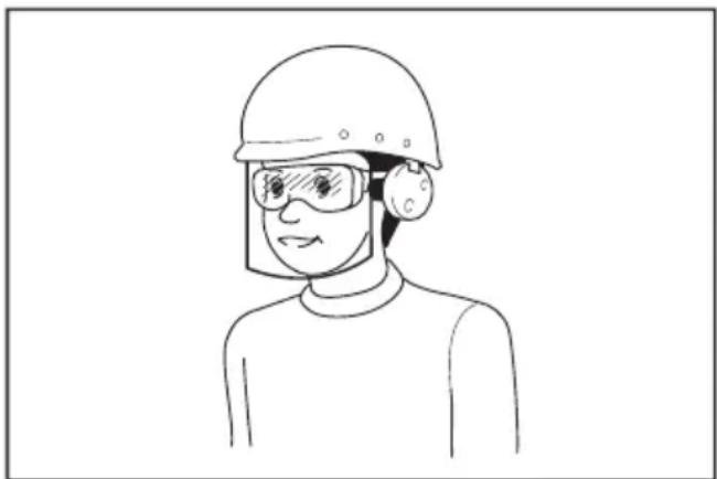
- Always wear protective goggles to protect your eyes from injury when using power tools. The goggles must comply with ANSI Z87.1 in the USA, EN 166 in Europe, or AS/NZS 1336 in Australia/New Zealand. In Australia/New Zealand, it is legally required to wear a face shield to protect your face, too.
natural_image
Line drawing of a person wearing a helmet and safety goggles (no text or symbols)It is an employer's responsibility to enforce the use of appropriate safety protective equipments by the tool operators and by other persons in the immediate working area.
Power tool use and care
- Do not force the power tool. Use the correct power tool for your application. The correct power tool will do the job better and safer at the rate for which it was designed.
-
Do not use the power tool if the switch does not turn it on and off. Any power tool that cannot be controlled with the switch is dangerous and must be repaired.
-
Disconnect the plug from the power source and/or remove the battery pack, if detachable, from the power tool before making any adjustments, changing accessories, or storing power tools. Such preventive safety measures reduce the risk of starting the power tool accidentally.
- Store idle power tools out of the reach of children and do not allow persons unfamiliar with the power tool or these instructions to operate the power tool. Power tools are dangerous in the hands of untrained users.
- Maintain power tools and accessories. Check for misalignment or binding of moving parts, breakage of parts and any other condition that may affect the power tool's operation. If damaged, have the power tool repaired before use. Many accidents are caused by poorly maintained power tools.
- Keep cutting tools sharp and clean. Properly maintained cutting tools with sharp cutting edges are less likely to bind and are easier to control.
- Use the power tool, accessories and tool bits etc. in accordance with these instructions, taking into account the working conditions and the work to be performed. Use of the power tool for operations different from those intended could result in a hazardous situation.
- Keep handles and grasping surfaces dry, clean and free from oil and grease. Slippery handles and grasping surfaces do not allow for safe handling and control of the tool in unexpected situations.
- When using the tool, do not wear cloth work gloves which may be entangled. The entanglement of cloth work gloves in the moving parts may result in personal injury.
Battery tool use and care
- Recharge only with the charger specified by the manufacturer. A charger that is suitable for one type of battery pack may create a risk of fire when used with another battery pack.
- Use power tools only with specifically designated battery packs. Use of any other battery packs may create a risk of injury and fire.
- When battery pack is not in use, keep it away from other metal objects, like paper clips, coins, keys, nails, screws or other small metal objects, that can make a connection from one terminal to another. Shorting the battery terminals together may cause burns or a fire.
- Under abusive conditions, liquid may be ejected from the battery; avoid contact. If contact accidentally occurs, flush with water. If liquid contacts eyes, additionally seek medical help. Liquid ejected from the battery may cause irritation or burns.
- Do not use a battery pack or tool that is damaged or modified. Damaged or modified batteries may exhibit unpredictable behaviour resulting in fire, explosion or risk of injury.
-
Do not expose a battery pack or tool to fire or excessive temperature. Exposure to fire or temperature above 130 °C may cause explosion.
-
Follow all charging instructions and do not charge the battery pack or tool outside the temperature range specified in the instructions. Charging improperly or at temperatures outside the specified range may damage the battery and increase the risk of fire.
Service
- Have your power tool serviced by a qualified repair person using only identical replacement parts. This will ensure that the safety of the power tool is maintained.
- Never service damaged battery packs. Service of battery packs should only be performed by the manufacturer or authorized service providers.
- Follow instruction for lubricating and changing accessories.
Cordless garden blower safety warnings
The term “blower” and “machine” in the warnings and precautions refer to the combination of the attachment and the power unit.
- Do not use the machine in bad weather conditions, especially when there is a risk of lightning. This decreases the risk of being struck by lightning.
- Wear eye protection and ear protection. Adequate protective equipment will reduce the risk of personal injury.
- While operating the machine, always wear non-slip and protective footwear. Do not operate the machine when barefoot or wearing open sandals. This reduces the risk of injury to the feet.
- Do not wear loose fitting clothing or articles such as scarves, strings, chains, ties, etc., that could get drawn into the air inlets. Tie back or cover long hair to make sure it does not get drawn into the air inlets. If any of these items are drawn into the air inlets, it can increase the risk of personal injury.
- Keep bystanders away while operating the machine. Thrown debris can increase the risk of personal injury.
- Never point the blower nozzle in the direction of people or pets or in the direction of windows. Use extra caution when blowing debris near solid objects, such as trees, automobiles and walls that can cause debris to ricochet. Thrown objects can damage property and increase the risk of personal injury.
- Do not use the machine to blow anything that is burning or smoking, such as cigarettes, matches or hot ashes. These ignition sources may increase the risk of fire.
-
Do not touch the fan while still in motion. Turn off the machine and wait until the fan stops before removing any part that may give access to the fan. This reduces the risk of injury from moving parts.
-
When clearing jammed material or servicing the machine, make sure the power switch is off. Unexpected starting of the machine while clearing jammed material or servicing may result in serious personal injury.
- Foreign substance may block the air channels and laden air flows. Remove any obstacles in the air path if the blowing performance is being affected.
- Always wear gloves during operation. Avoid operating the machine with your bare hands. This reduces the risk of injury to the hands and fingers.
- Use this machine at ground level, not on ladders or any unstable support.
- When the machine strikes a hard object or if there appears to be excessive vibration, inspect the machine for damage.
- Always make sure that the ventilation openings are kept clear of debris.
- Clean the machine before storage.
Additional Safety Instructions
- Operate the machine only in daylight or in good artificial light. Do not use the machine where visibility is limited. Failure to do so may cause fall or incorrect operation due to low visibility.
- Do not operate the blower at high places.
- Operate the blower in a recommended position and on a firm surface.
SAVE THESE INSTRUCTIONS.
⚠ WARNING: DO NOT let comfort or familiarity with product (gained from repeated use) replace strict adherence to safety rules for the subject product.
MISUSE or failure to follow the safety rules stated in this instruction manual may cause serious personal injury.
PARTS DESCRIPTION
▶ Fig.1: 1. Cap 2. Pipe 3. End nozzle
ASSEMBLY
WARNING: Before assembling or adjusting the equipment, switch off the motor and remove the battery cartridge. Otherwise, the fans may move and result in an injury.
WARNING: When assembling or adjusting the equipment, always put it down. Assembling or adjusting the equipment in an upright position may result in serious injury.
WARNING: Follow the warnings and precautions in the chapter "SAFETY WARNINGS" and the instruction manual of the power unit.
Mounting the attachment pipe
⚠️CAUTION: Always check that the attachment pipe is secured after installation. Improper installation may cause the attachment falling off from the power unit and cause personal injury.
Mount the attachment pipe to the power unit.
- Remove the cap from the end of the pipe.
▶ Fig.2: 1. Pipe 2. Cap
NOTICE: Do not dispose of the cap since the cap is necessary for storing the attachment.
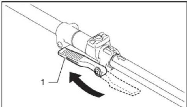
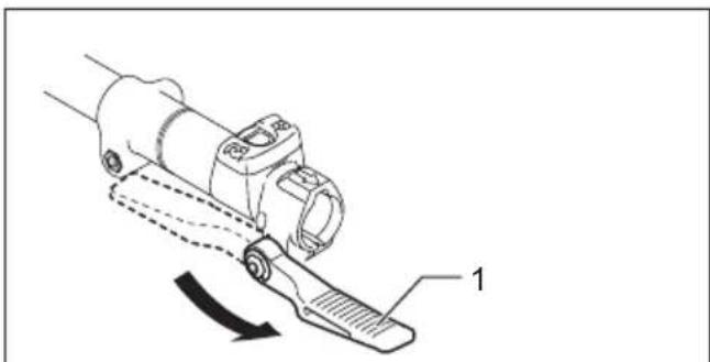
- Turn the lever of the power unit towards the attachment.
▶ Fig.3: 1. Lever
- Align the spring rivet on the pipe with the arrow mark on the power unit. Insert the pipe until the release button pops up.
Make sure that the position line is on the tip of the arrow mark on the power unit, and the arrow marks on both the pipe and power unit face each other.
▶ Fig.4: 1. Release button 2. Arrow mark on the power unit 3. Spring rivet 4. Position line 5. Arrow mark on the pipe
- Turn the lever back towards the power unit.
▶ Fig.5: 1. Lever
Make sure that the surface of the lever is parallel to the pipe.
NOTICE: Do not tighten the lever without the attachment pipe inserted. Otherwise the lever may tighten the entrance of the drive shaft too much and damage it.
To remove the pipe, turn the lever towards the attachment and pull the pipe out while pressing down the release button.
▶ Fig.6: 1. Lever 2. Release button 3. Pipe
End nozzle assembly
The blower attachment is standard equipped with a detachable end nozzle. Adjust or replace the nozzle according to your preferences.
Removing end nozzle
Holding the attachment body, turn and slide the end nozzle away along the guide groove towards the front direction.
▶ Fig.7: 1. End nozzle 2. Guide groove 3. Blower outlet
Attaching end nozzle
Align the guide groove on the end nozzle with the fitting projection on the blower outlet. Slide and turn the end nozzle back along the guide groove to secure it in place with a click.
▶ Fig.8: 1. End nozzle 2. Blower outlet 3. Guide groove 4. Fitting projection 5. Triangle symbols
NOTE: Be sure to lock the end nozzle securely so one of the three triangle symbols on the blower outlet and that on the end nozzle face each other.
Adjusting nozzle length
Set the end nozzle in one of three lengths according to your applications.
Holding the attachment body, turn and slide the end nozzle back and forwards along the guide groove to lock it at your desired position with a click.
▶ Fig.9: 1. End nozzle 2. Guide groove 3. Triangle symbols
Attaching and removing flat nozzle/extension nozzle
Optional accessory
- Holding the attachment body, turn and slide the end nozzle away along the guide groove towards the front direction.
▶ Fig.10: 1. End nozzle 2. Guide groove 3. Blower outlet - Align the guide groove on the adapter pipe with the fitting projection on the blower outlet. Slide and turn the adapter pipe back along the guide groove to secure it in place with a click.
▶ Fig.11: 1. Adapter pipe 2. Blower outlet 3. Guide groove 4. Fitting projection 5. Triangle symbols
NOTE: Be sure to lock the adapter pipe securely so the front of the three triangle symbols on the blower outlet and that on the adapter pipe face each other.
- Align the guide groove on the nozzle attachment with the fitting projection on the adapter pipe. Slide and turn the nozzle attachment back and forwards along the guide groove to secure it in your desired position with a click.
▶ Fig.12: 1. Flat nozzle 2. Extension nozzle 3. Adapter pipe 4. Guide groove 5. Fitting projection 6. Triangle symbols
NOTE: Be sure to lock the nozzle attachment securely so either of two triangle symbols on the adapter pipe and that on the nozzle attachment face each other.
- To remove the nozzle attachment, perform the installation procedure in reverse.
Installing gutter nozzle set
Optional accessory
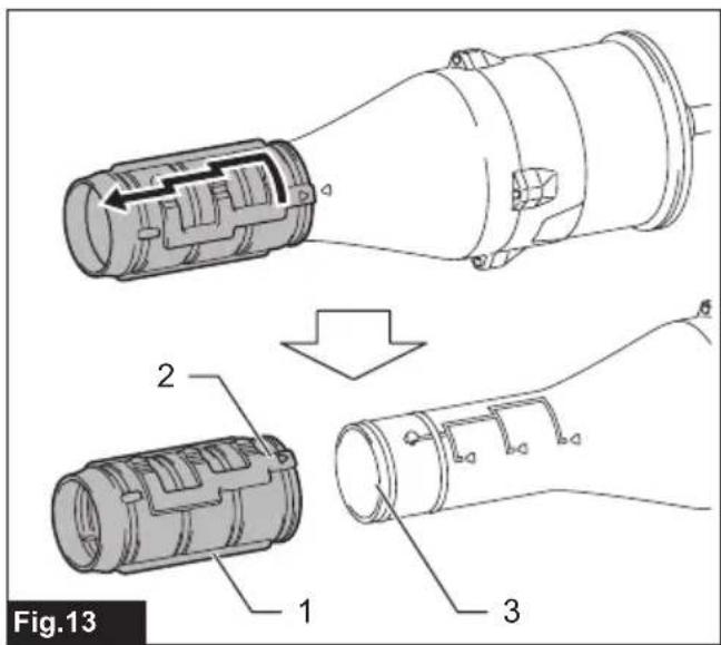
- Holding the attachment body, turn and slide the end nozzle away along the guide groove towards the front direction.
▶ Fig.13: 1. End nozzle 2. Guide groove 3. Blower outlet
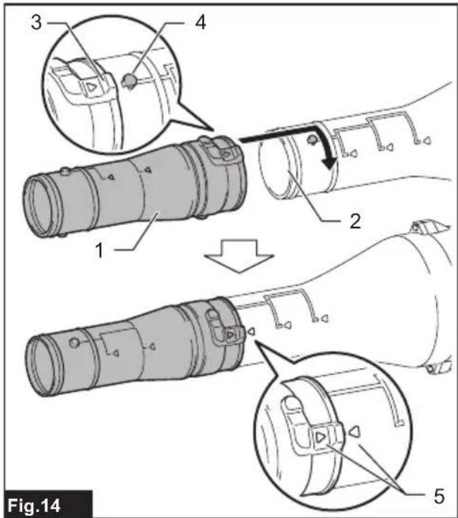
- Align the guide groove on the adapter pipe with the fitting projection on the blower outlet. Slide and turn the adapter pipe back along the guide groove to secure it in place with a click.
▶ Fig.14: 1. Adapter pipe 2. Blower outlet 3. Guide groove 4. Fitting projection 5. Triangle symbols
NOTE: Be sure to lock the adapter pipe securely so the front of the three triangle symbols on the blower outlet and that on the adapter pipe face each other.
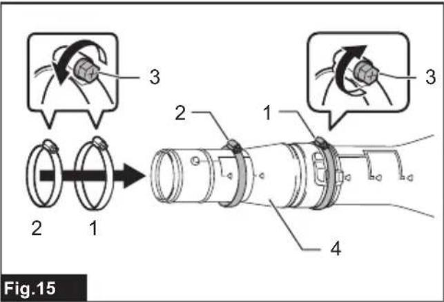
- Loosen a large hose clamp by unscrewing, and pass it through the adapter pipe.
- Place the hose clamp (large) over the guide groove on the adapter pipe. Tighten the hose clamp (large) to secure the assembly.
- Loosen a small hose clamp by unscrewing, and pass it through the adapter pipe.
▶ Fig.15: 1. Hose clamp (large) 2. Hose clamp (small)
-
Screw 4. Adapter pipe
-
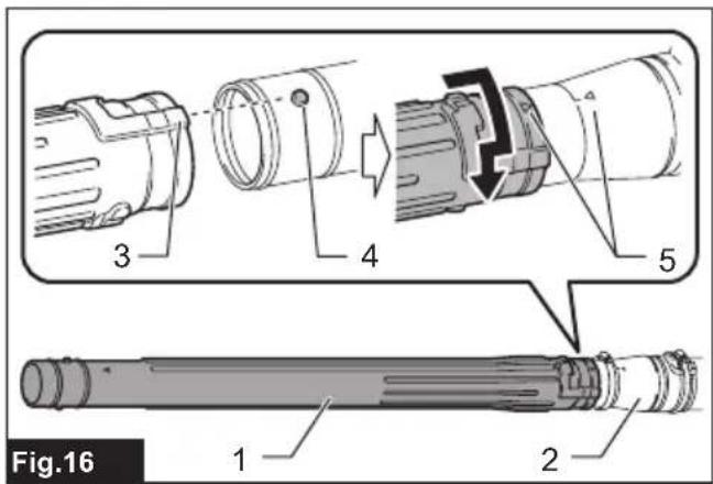
Align the guide groove on the extension pipe with the fitting projection on the adapter pipe. Slide and turn the extension pipe back along the guide groove to secure it in place with a click.
▶ Fig.16: 1. Extension pipe 2. Adapter pipe 3. Guide groove 4. Fitting projection 5. Triangle symbols
NOTE: Be sure to lock the extension pipe securely so the rear of the two triangle symbols on the adapter pipe and that on the extension pipe point at each other.
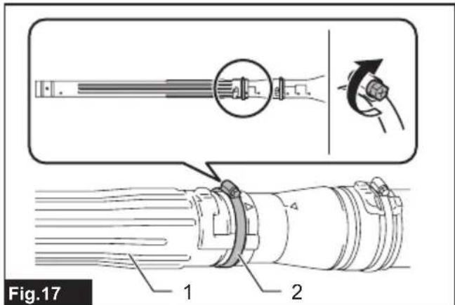
- Place the hose clamp (small) over the guide groove on the extension pipe. Tighten the hose clamp (small) to secure the assembly.
▶ Fig.17: 1. Extension pipe 2. Hose clamp (small)
- Extend the blower's reach using extra extension pipes if needs arise.
⚠️CAUTION: When installing the gutter nozzle set in the blower attachment, do not use three or more extension pipes. It may cause imbalance and result in injury.
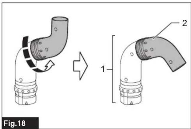
- Prepare the end nozzle to make a narrow blowing angle by turning its nozzle head.
▶ Fig.18: 1. End nozzle 2. Nozzle head
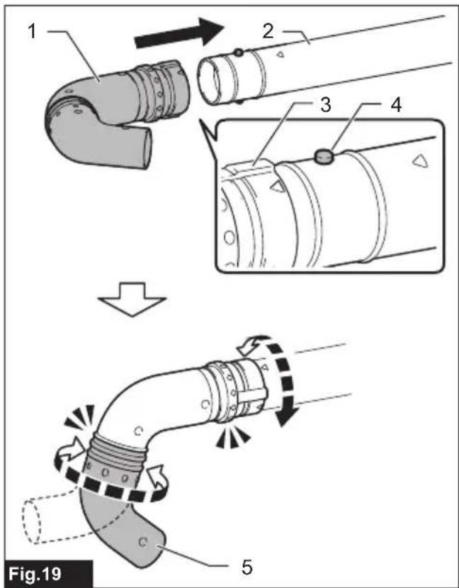
- Align the guide groove on the end nozzle with the fitting projection on the extension pipe. Slide the end nozzle back all the way along the guide groove until it locks with a click.
Rotate the end nozzle and nozzle head as your needs change. Blowing angle can be adjusted at will after installation to meet your various angle needs.
▶ Fig.19: 1. End nozzle 2. Extension pipe 3. Guide groove 4. Fitting projection 5. Nozzle head
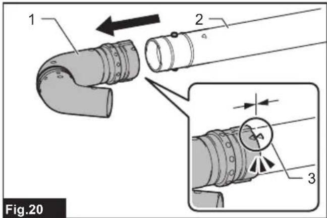
To disassemble a set, turn the end nozzle first to align the triangle symbols on the end nozzle and extension pipe. Then pull the end nozzle apart from the extension pipe.
▶ Fig.20: 1. End nozzle 2. Extension pipe 3. Triangle symbols
OPERATION
WARNING: Follow the warnings and precautions in the chapter "SAFETY WARNINGS" and the instruction manual of the power unit.
WARNING: Adjust the hanger position and shoulder harness to your comfortable position before operating.
Blower operation
CAUTION: Do not place the machine on the ground while it is switched on. Sand or dust may enter from air inlet and cause a malfunction or personal injury.
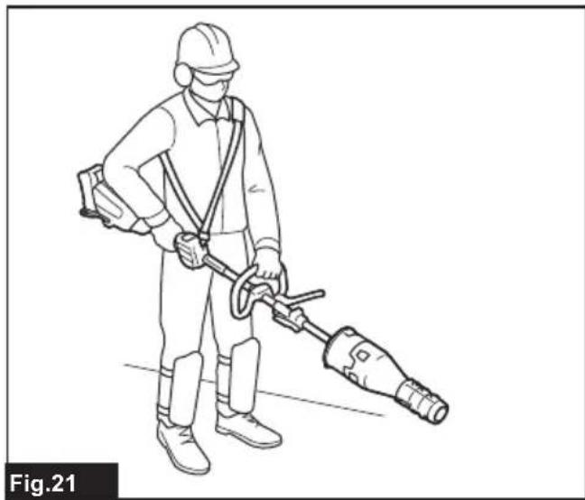
Hold the machine firmly with both hands and perform the blowing operation by moving it around slowly. When blowing around building, big stone or vehicle, direct the nozzle away from them. When performing an operation in a corner, start from the corner and then move to wide area.
Adjust the air speed with the switch trigger of the power unit according to the environment or conditions of your usage.
▶ Fig.21
Using gutter nozzle set
CAUTION: When using the gutter nozzle set, do not hold the blower with single hand but with both hands.
▶ Fig.22
⚠️ CAUTION: Do not use the gutter nozzle set near electric wires.
▶ Fig.23
CAUTION: Do not use the gutter nozzle set on windy day.
▶ Fig.24
⚠️ CAUTION: When using the gutter nozzle set, keep other people or animal more than 15 m away from the blower.
▶ Fig.25
Hold the blower upright by grabbing the handle of the blower. Place the outlet of the blower on the gutter and then turn on the blower.
▶ Fig.26
MAINTENANCE
WARNING: Before inspecting or maintaining the equipment, switch off the motor and remove the battery cartridge. Otherwise, the fans may move and result in serious injury.
WARNING: When inspecting or maintaining the equipment, always put it down. Assembling or adjusting the equipment in an upright position may result in serious injury.
WARNING: Follow the warnings and precautions in the chapter "SAFETY WARNINGS" and the instruction manual of the power unit.
NOTICE: Never use gasoline, benzine, thinner, alcohol or the like. Discoloration, deformation or cracks may result.
To maintain product SAFETY and RELIABILITY, repairs, any other maintenance or adjustment should be performed by Makita Authorized or Factory Service Centers, always using Makita replacement parts.
Cleaning the machine
Clean the machine by wiping off dust with a dry cloth or one dipped in soapy water and wrung out.
▶ Fig.27
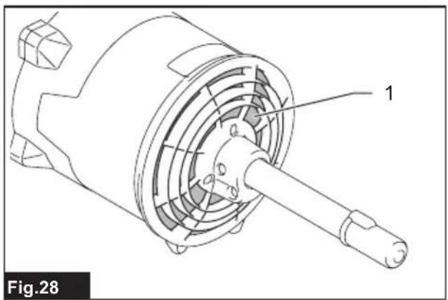
Remove dust or dirt from the air inlet at the rear of the attachment.
▶ Fig.28: 1. Air inlet
Overall inspection
Check for damaged parts. Ask our authorized service center to replace them if necessary.
Lubricating moving parts
NOTICE: Follow the instruction of the frequency and amount of grease supplied. Otherwise insufficient lubrication may damage moving parts.
Drive axle:
Apply grease (Makita grease N No.2 or equivalent) every 30 hours of operation.
▶ Fig.29
NOTE: Genuine Makita grease may be purchased from your local Makita dealer.
Storage
When storing the attachment separated from the power unit, put the cap onto the end of the pipe.
▶ Fig.30
Interval of inspection and maintenance
| Operating hour Before | Operation | Daily (10 hours) | 30 hours | |
| Whole unit Visually inspect for damage | maged parts | √ | - | - |
| Drive axle Supply grease -- | √ | |||
| Power unit Refer to the instruction manual of the power unit | ||||
TROUBLESHOOTING
Before asking for repairs, conduct your own inspection first. If you find a problem that is not explained in the manual, do not attempt to disassemble the machine. Instead, ask Makita Authorized Service Centers, always using Makita replacement parts for repairs.
| State of abnormality Probable cause | (malfunction) Remedy | |
| Motor does not start. - Refer to the instruction manual of the power unit. | ||
| Motor stops soon. | - | Refer to the instruction manual of the power unit. |
| Motor speed does not increase. | - | Refer to the instruction manual of the power unit. |
| Fans do not rotate.⇒ Stop the motor immediately. | The pipes of the power unit and the attachment are not connected properly. | Connect the pipes in the correct way. |
| Abnormal drive system | Contact an authorized service center for repairs. | |
| Power unit vibrates abnormally.⇒ Stop the motor immediately. | Abnormal drive system | Contact an authorized service center for repairs. |
| Fans continue to rotate even if the switch trigger is released.⇒ Stop the motor immediately. | The power unit does not work properly. | Contact an authorized service center for repairs. |
OPTIONAL ACCESSORIES
⚠️CAUTION: These accessories or attachments are recommended for use with your Makita machine specified in this manual. The use of any other accessories or attachments might present a risk of injury to persons. Only use accessory or attachment for its stated purpose.
If you need any assistance for more details regarding these accessories, ask your local Makita Service Center.
- Adapter pipe
- Extension nozzle
- Flat nozzle
- Gutter nozzle set
- Makita genuine battery and charger
NOTE: Some items in the list may be included in the product package as standard accessories. They may differ from country to country.
SPÉCIFICATIONS
natural_image
Line drawing of a person wearing a hard hat and safety goggles (no text or symbols)natural_image
Line drawing of a person wearing a helmet and safety goggles (no text or symbols)natural_image
Line drawing of a person wearing a hard hat and safety goggles (no text or symbols)VEILIGHEIDSWAAR- SCHUWINGEN
natural_image
Line drawing of a person wearing a hard hat and safety goggles (no text or symbols)OPTIONELE ACCESSOIRES
natural_image
Line drawing of a person wearing a helmet and safety goggles (no text or symbols)natural_image
Line drawing of a person wearing a hard hat and safety goggles (no text or symbols)▶ Fig.1: 1. Tampa 2. Tubo 3. Bocal final
MONTAGEM
natural_image
Line drawing of a person wearing a hard hat and safety goggles (no text or symbols)natural_image
Line drawing of a person wearing a helmet and safety goggles (no text or symbols)İthalatçı: Makita (UK) Limited, Michigan Drive, Tongwell, Milton Keynes, Buckinghamshire, MK15 8JD, BK
GÜVENLİK UYARILARI
natural_image
Line drawing of a person wearing a helmet and safety goggles (no text or symbols)natural_image
Line drawing of a person wearing a helmet and safety goggles (no text or symbols)natural_image
Line drawing of a person wearing a helmet and safety goggles (no text or symbols)natural_image
Line drawing of a person wearing a helmet and safety goggles (no text or symbols)natural_image
Line drawing of a person wearing a hard hat and safety goggles (no text or symbols)natural_image
Line drawing of a person wearing a helmet and safety goggles (no text or symbols)Importija: Makita (UK) Limited, Michigan Drive, Tongwell, Milton Keynes, Buckinghamshire, MK15 8JD, ÜK
OHUTUSHOIATUSED
natural_image
Line drawing of a person wearing a helmet and safety goggles (no text or symbols)natural_image
Line drawing of a person wearing a hard hat and safety goggles (no text or symbols)natural_image
Line drawing of a person wearing a hard hat and safety goggles (no text or symbols)natural_image
Line drawing of a person wearing a helmet and safety goggles (no text or symbols)TIETO POKYNY USCHOVAJTE.
natural_image
Line drawing of a person wearing a helmet and safety goggles (no text or symbols)TYTO POKYNY USCHOVEJTE.
VOLITELNÉ PŘÍSLUŠENSTVÍ
Uvoznik: Makita (UK) Limited, Michigan Drive, Tongwell, Milton Keynes, Buckinghamshire, MK15 8JD, UK

VARNOSTNA OPOZORILA
natural_image
Line drawing of a person wearing a helmet and safety goggles (no text or symbols)Importues: Makita (UK) Limited, Michigan Drive, Tongwell, Milton Keynes, Buckinghamshire, MK15 8JD, UK

PARALAJMËRIME SIGURIE
natural_image
Line drawing of a person wearing a helmet and safety goggles (no text or symbols)natural_image
Line drawing of a person wearing a helmet and safety goggles (no text or symbols)natural_image
Line drawing of a person wearing a hard hat and safety goggles (no text or symbols)natural_image
Line drawing of a person wearing a helmet and safety goggles (no text or symbols)natural_image
Line drawing of a person wearing a helmet and safety goggles (no text or symbols)Importator: Makita (UK) Limited, Michigan Drive, Tongwell, Milton Keynes, Buckinghamshire, MK15 8JD, Regatul Unit
AVERTIZĂRI DE SIGURANTĂ
natural_image
Line drawing of a person wearing a hard hat and safety goggles (no text or symbols)natural_image
Line drawing of a person wearing a helmet and safety goggles (no text or symbols)natural_image
Line drawing of a person wearing a hard hat and safety goggles (no text or symbols)natural_image
Line drawing of a person wearing a helmet and safety goggles (no text or symbols)進口商:Makita (UK) Limited, Michigan Drive, Tongwell, Milton Keynes, Buckinghamshire, MK15 8JD, UK