
MP001G - Compressor MAKITA - Free user manual and instructions
Find the device manual for free MP001G MAKITA in PDF.
User questions about MP001G MAKITA
0 question about this device. Answer the ones you know or ask your own.
Ask a new question about this device
Download the instructions for your Compressor in PDF format for free! Find your manual MP001G - MAKITA and take your electronic device back in hand. On this page are published all the documents necessary for the use of your device. MP001G by MAKITA.
USER MANUAL MP001G MAKITA
| Model: MP001G | |
| Overall length with BL4025 320 mm | |
| with BL4040 336 mm | |
| Maximum air pressure 1,100 kPa | |
| Duty cycle 10 minutes On / 5 minutes Off | |
| Rated voltage D.C. 36 V - 40 V max | |
| Net weight 2.8 - 3.1 kg |
- Due to our continuing program of research and development, the specifications herein are subject to change without notice.
- Specifications and battery cartridge may differ from country to country.
The weight may differ depending on the attachment(s), including the battery cartridge. The lightest and heaviest combinations, according to EPTA-Procedure 01/2014, are shown in the table.
Applicable battery cartridge and charger
Battery cartridge BL4020 / BL4025 / BL4040 / BL4050F
Charger DC40RA / DC40RB / DC40RC
- Some of the battery cartridges and chargers listed above may not be available depending on your region of residence.

WARNING: Only use the battery cartridges and chargers listed above. Use of any other battery cartridges and chargers may cause injury and/or fire.
Symbols
The followings show the symbols which may be used for the equipment. Be sure that you understand their meaning before use.

Read instruction manual.

Risk of bursting.

Ni-MH
Li-ion
Only for EU countries
Due to the presence of hazardous components in the equipment, waste electrical and electronic equipment, accumulators and batteries may have a negative impact on the environment and human health.
Do not dispose of electrical and electronic appliances or batteries with household waste!
In accordance with the European Directive on waste electrical and electronic equipment and on accumulators and batteries and waste accumulators and batteries,
as well as their adaptation to national law, waste electrical equipment, batteries and accumulators should be stored separately and delivered to a separate collection point for municipal waste, operating in accordance with the regulations on environmental protection.
This is indicated by the symbol of the crossed-out wheeled bin placed on the equipment.
Intended use
This tool is intended for inflating tire, sport ball, or small floating tube.
Noise
The typical A-weighted noise level determined according to EN62841-1:
Sound pressure level (L_pA):71dB(A)
Uncertainty (K): 3 dB(A)
The noise level under working may exceed 80 dB (A).
NOTE: The declared noise emission value(s) has been measured in accordance with a standard test method and may be used for comparing one tool with another.
NOTE: The declared noise emission value(s) may also be used in a preliminary assessment of exposure.
WARNING: Wear ear protection.
WARNING: The noise emission during actual use of the power tool can differ from the declared value(s) depending on the ways in which the tool is used especially what kind of workpiece is processed.
WARNING: Be sure to identify safety measures to protect the operator that are based on an estimation of exposure in the actual conditions of use (taking account of all parts of the operating cycle such as the times when the tool is switched off and when it is running idle in addition to the trigger time).
Vibration
The vibration total value (tri-axial vector sum) determined according to EN62841-1:
Work mode: Inflating (1,100 kPa)
Vibration emission (_h):3.8~m / s^2
Uncertainty (K): 1.5m / s^2
NOTE: The declared vibration total value(s) has been measured in accordance with a standard test method and may be used for comparing one tool with another.
NOTE: The declared vibration total value(s) may also be used in a preliminary assessment of exposure.
WARNING: The vibration emission during actual use of the power tool can differ from the declared value(s) depending on the ways in which the tool is used especially what kind of workpiece is processed.
WARNING: Be sure to identify safety measures to protect the operator that are based on an estimation of exposure in the actual conditions of use (taking account of all parts of the operating cycle such as the times when the tool is switched off and when it is running idle in addition to the trigger time).
EC Declaration of Conformity
For European countries only
The EC declaration of conformity is included as Annex A to this instruction manual.
SAFETYWARNINGS
General power tool safety warnings
WARNING: Read all safety warnings, instructions, illustrations and specifications provided with this power tool. Failure to follow all instructions listed below may result in electric shock, fire and/or serious injury.
Save all warnings and instructions for future reference.
The term "power tool" in the warnings refers to your mains-operated (corded) power tool or battery-operated (cordless) power tool.
Work area safety
- Keep work area clean and well lit. Cluttered or dark areas invite accidents.
- Do not operate power tools in explosive atmospheres, such as in the presence of flammable liquids, gases or dust. Power tools create sparks which may ignite the dust or fumes.
- Keep children and bystanders away while operating a power tool. Distractions can cause you to lose control.
Electrical safety
- Power tool plugs must match the outlet. Never modify the plug in any way. Do not use any adapter plugs with earthed (grounded) power tools. Unmodified plugs and matching outlets will reduce risk of electric shock.
- Avoid body contact with earthed or grounded surfaces, such as pipes, radiators, ranges and refrigerators. There is an increased risk of electric shock if your body is earthed or grounded.
- Do not expose power tools to rain or wet conditions. Water entering a power tool will increase the risk of electric shock.
- Do not abuse the cord. Never use the cord for carrying, pulling or unplugging the power tool. Keep cord away from heat, oil, sharp edges or moving parts. Damaged or entangled cords increase the risk of electric shock.
- When operating a power tool outdoors, use an extension cord suitable for outdoor use. Use of a cord suitable for outdoor use reduces the risk of electric shock.
- If operating a power tool in a damp location is unavoidable, use a residual current device (RCD) protected supply. Use of an RCD reduces the risk of electric shock.
- Power tools can produce electromagnetic fields (EMF) that are not harmful to the user. However, users of pacemakers and other similar medical devices should contact the maker of their device and/or doctor for advice before operating this power tool.
Personal safety
- Stay alert, watch what you are doing and use common sense when operating a power tool. Do not use a power tool while you are tired or under the influence of drugs, alcohol or medication. A moment of inattention while operating power tools may result in serious personal injury.
-
Use personal protective equipment. Always wear eye protection. Protective equipment such as a dust mask, non-skid safety shoes, hard hat or hearing protection used for appropriate conditions will reduce personal injuries.
-
Prevent unintentional starting. Ensure the switch is in the off-position before connecting to power source and/or battery pack, picking up or carrying the tool. Carrying power tools with your finger on the switch or energising power tools that have the switch on invites accidents.
- Remove any adjusting key or wrench before turning the power tool on. A wrench or a key left attached to a rotating part of the power tool may result in personal injury.
- Do not overreach. Keep proper footing and balance at all times. This enables better control of the power tool in unexpected situations.
- Dress properly. Do not wear loose clothing or jewellery. Keep your hair and clothing away from moving parts. Loose clothes, jewellery or long hair can be caught in moving parts.
- If devices are provided for the connection of dust extraction and collection facilities, ensure these are connected and properly used. Use of dust collection can reduce dust-related hazards.
- Do not let familiarity gained from frequent use of tools allow you to become complacent and ignore tool safety principles. A careless action can cause severe injury within a fraction of a second.
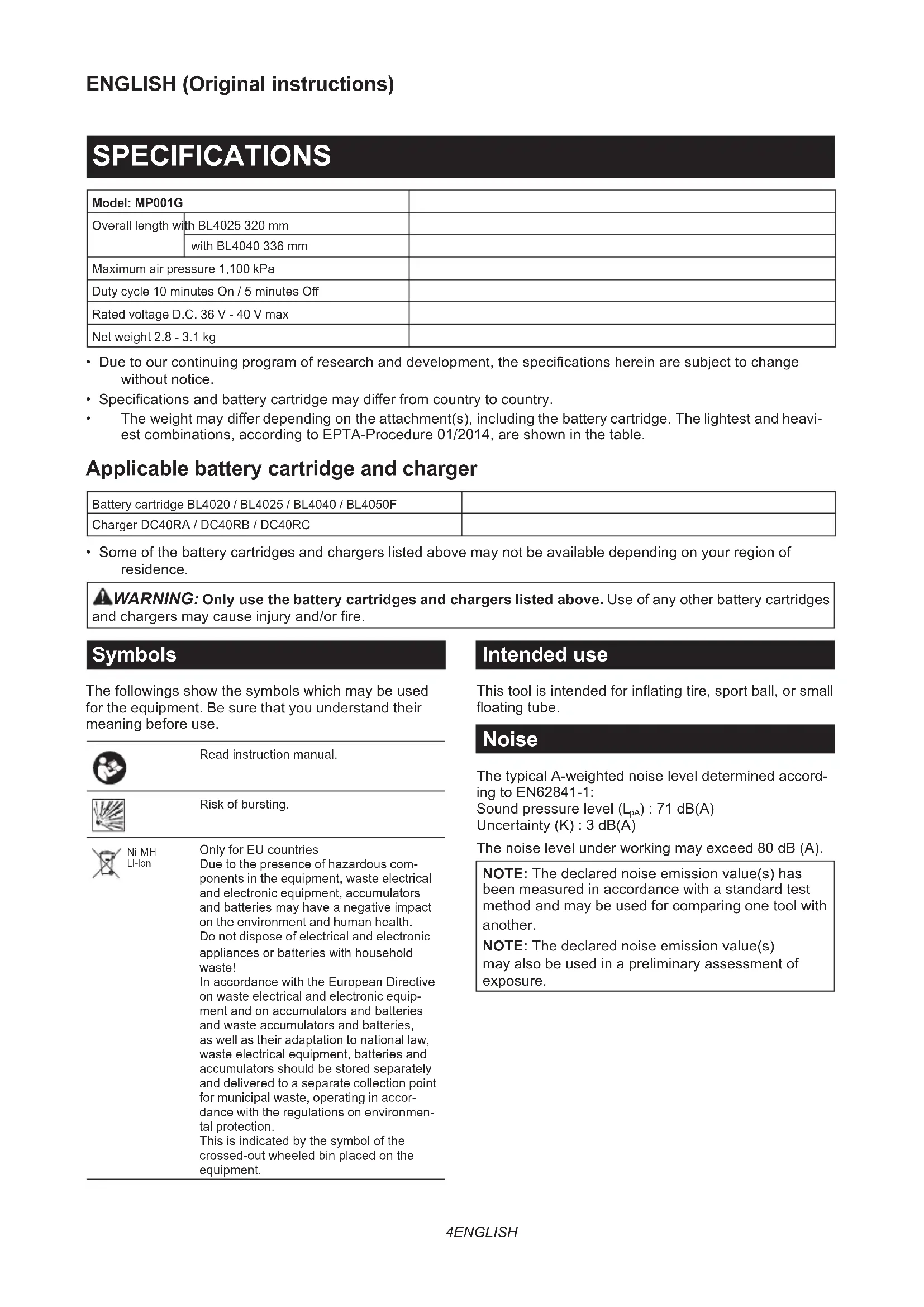
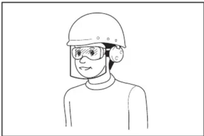
- Always wear protective goggles to protect your eyes from injury when using power tools. The goggles must comply with ANSI Z87.1 in the USA, EN 166 in Europe, or AS/NZS 1336 in Australia/New Zealand. In Australia/New Zealand, it is legally required to wear a face shield to protect your face, too.
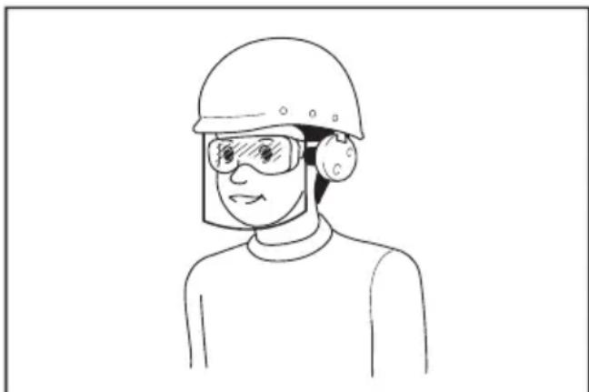
It is an employer's responsibility to enforce the use of appropriate safety protective equipments by the tool operators and by other persons in the immediate working area.
Power tool use and care
- Do not force the power tool. Use the correct power tool for your application. The correct power tool will do the job better and safer at the rate for which it was designed.
-
Do not use the power tool if the switch does not turn it on and off. Any power tool that cannot be controlled with the switch is dangerous and must be repaired.
-
Disconnect the plug from the power source and/or remove the battery pack, if detachable, from the power tool before making any adjustments, changing accessories, or storing power tools. Such preventive safety measures reduce the risk of starting the power tool accidentally.
- Store idle power tools out of the reach of children and do not allow persons unfamiliar with the power tool or these instructions to operate the power tool. Power tools are dangerous in the hands of untrained users.
- Maintain power tools and accessories. Check for misalignment or binding of moving parts, breakage of parts and any other condition that may affect the power tool's operation. If damaged, have the power tool repaired before use. Many accidents are caused by poorly maintained power tools.
- Keep cutting tools sharp and clean. Properly maintained cutting tools with sharp cutting edges are less likely to bind and are easier to control.
- Use the power tool, accessories and tool bits etc. in accordance with these instructions, taking into account the working conditions and the work to be performed. Use of the power tool for operations different from those intended could result in a hazardous situation.
- Keep handles and grasping surfaces dry, clean and free from oil and grease. Slippery handles and grasping surfaces do not allow for safe handling and control of the tool in unexpected situations.
- When using the tool, do not wear cloth work gloves which may be entangled. The entanglement of cloth work gloves in the moving parts may result in personal injury.
Battery tool use and care
- Recharge only with the charger specified by the manufacturer. A charger that is suitable for one type of battery pack may create a risk of fire when used with another battery pack.
- Use power tools only with specifically designated battery packs. Use of any other battery packs may create a risk of injury and fire.
- When battery pack is not in use, keep it away from other metal objects, like paper clips, coins, keys, nails, screws or other small metal objects, that can make a connection from one terminal to another. Shorting the battery terminals together may cause burns or a fire.
- Under abusive conditions, liquid may be ejected from the battery; avoid contact. If contact accidentally occurs, flush with water. If liquid contacts eyes, additionally seek medical help. Liquid ejected from the battery may cause irritation or burns.
- Do not use a battery pack or tool that is damaged or modified. Damaged or modified batteries may exhibit unpredictable behaviour resulting in fire, explosion or risk of injury.
-
Do not expose a battery pack or tool to fire or excessive temperature. Exposure to fire or temperature above 130^ may cause explosion.
-
Follow all charging instructions and do not charge the battery pack or tool outside the temperature range specified in the instructions. Charging improperly or at temperatures outside the specified range may damage the battery and increase the risk of fire.
Service
- Have your power tool serviced by a qualified repair person using only identical replacement parts. This will ensure that the safety of the power tool is maintained.
- Never service damaged battery packs. Service of battery packs should only be performed by the manufacturer or authorized service providers.
- Follow instruction for lubricating and changing accessories.
Cordless inflator safety warnings
- When inflating objects, connect the air chuck, adapter, and valve tightly. Otherwise, the object, hose, air chuck, or adapter may be damaged and you may be injured.
- Release air pressure slowly. When removing the hose after inflating objects, hold the object, hose, and air chuck firmly. The object, air chuck, or adapter may bounce due to exhaust air and cause an injury.
- Do not inflate object beyond the maximum pressure of the object. Otherwise, the tool or object may be damaged and you may be injured.
- Do not use the tool beyond the maximum output pressure of the tool. Using the tool at output pressure greater than the maximum output pressure of the tool may burst the object or the tool.
- Inflate the objects intended to be inflated by the manufacturer only, such as tire, sport ball, or small floating tube. Inflating other objects may damage them and cause an injury.
- When inflating objects, check the pressure gauge, status of the tool and object, and check that there is no air leak. Otherwise, the tool or object may be damaged and cause an injury.
- When carrying the tool, hold the handle of the tool. Do not hold or pull the hose. The tool may be damaged and cause an injury.
- After inflating objects, check the air pressure using a reliable and calibrated measuring equipment. Use the pressure gauge of the tool only as a reference.
- After using the tool for 10 minutes continuously, stop using the tool for 5 minutes for cooling down. Do not use the tool beyond the continuous operating time allowed. Otherwise, the tool may be damaged and cause an injury.
- Do not use the tool on sand or dusty surface. Foreign objects may enter the inside of the tool and cause a malfunction.
- Do not point the outlet of the hose to yourself or others. Objects may be blown away and cause an injury.
-
Do not point the outlet of the hose to dust or similar. The dust may be scattered and cause an injury.
-
Do not inflate large capacity objects. If you inflate a large capacity object, the tool may become extremely hot and could burn your skin.
- Do not touch the tool, hose, air chuck, or adapter right after inflating objects. The metal parts may become extremely hot and could burn your skin.
- Do not use the tool with wet hands.
- Make sure that the hose is not entangled. The entangled hose may cause loss of balance and cause an injury.
- Never leave the tool unattended when the hose is attached to the object or during operation.
- Do not use the tool as a breathing device.
- Do not use the tool to spray chemicals. Your lungs may be damaged by inhaling toxic fumes.
- Operate the tool in an open area at least 50~cm away from any wall or object that could restrict air flow to ventilation openings.
- Do not disassemble the tool.
- Use only standard accessories provided by Makita. The use of any other accessories or attachments might present a risk of injury to persons.
- Before you inflate a tire, make sure that there are no scratches or cracks in the tire. Damaged tire can burst when it is inflated and cause an injury.
- While you inflate a tire, do not stay in front of its sidewall.
Important safety instructions for battery cartridge
- Before using battery cartridge, read all instructions and cautionary markings on (1) battery charger, (2) battery, and (3) product using battery.
- Do not disassemble or tamper the battery cartridge. It may result in a fire, excessive heat, or explosion.
- If operating time has become excessively shorter, stop operating immediately. It may result in a risk of overheating, possible burns and even an explosion.
- If electrolyte gets into your eyes, rinse them out with clear water and seek medical attention right away. It may result in loss of your eyesight.
- Do not short the battery cartridge:
(1) Do not touch the terminals with any conductive material.
(2) Avoid storing battery cartridge in a container with other metal objects such as nails, coins, etc.
(3) Do not expose battery cartridge to water or rain.
A battery short can cause a large current flow, overheating, possible burns and even a breakdown.
-
Do not store and use the tool and battery cartridge in locations where the temperature may reach or exceed 50^ (122^) .
-
Do not incinerate the battery cartridge even if it is severely damaged or is completely worn out. The battery cartridge can explode in a fire.
- Do not nail, cut, crush, throw, drop the battery cartridge, or hit against a hard object to the battery cartridge. Such conduct may result in a fire, excessive heat, or explosion.
- Do not use a damaged battery.
- The contained lithium-ion batteries are subject to the Dangerous Goods Legislation requirements.
For commercial transports e.g. by third parties, forwarding agents, special requirement on packaging and labeling must be observed.
For preparation of the item being shipped, consulting an expert for hazardous material is required. Please also observe possibly more detailed national regulations.
Tape or mask off open contacts and pack up the battery in such a manner that it cannot move around in the packaging.
- When disposing the battery cartridge, remove it from the tool and dispose of it in a safe place. Follow your local regulations relating to disposal of battery.
- Use the batteries only with the products specified by Makita. Installing the batteries to non-compliant products may result in a fire, excessive heat, explosion, or leak of electrolyte.
- If the tool is not used for a long period of time, the battery must be removed from the tool.
- During and after use, the battery cartridge may take on heat which can cause burns or low temperature burns. Pay attention to the handling of hot battery cartridges.
- Do not touch the terminal of the tool immediately after use as it may get hot enough to cause burns.
- Do not allow chips, dust, or soil stuck into the terminals, holes, and grooves of the battery cartridge. It may result in poor performance or breakdown of the tool or battery cartridge.
- Unless the tool supports the use near high-voltage electrical power lines, do not use the battery cartridge near a high-voltage electrical power lines. It may result in a malfunction or breakdown of the tool or battery cartridge.
- Keep the battery away from children.
SAVE THESE INSTRUCTIONS.
CAUTION: Only use genuine Makita batteries.
Use of non-genuine Makita batteries, or batteries that have been altered, may result in the battery bursting causing fires, personal injury and damage. It will also void the Makita warranty for the Makita tool and charger.
Tips for maintaining maximum battery life
- Charge the battery cartridge before completely discharged. Always stop tool operation and charge the battery cartridge when you notice less tool power.
- Never recharge a fully charged battery cartridge. Overcharging shortens the battery service life.
- Charge the battery cartridge with room temperature at 10^ - 40^ (50°F - 104°F). Let a hot battery cartridge cool down before charging it.
- When not using the battery cartridge, remove it from the tool or the charger.
- Charge the battery cartridge if you do not use it for a long period (more than six months).
FUNCTIONAL DESCRIPTION
CAUTION: Always be sure that the tool is switched off and the battery cartridge is removed before adjusting or checking function on the tool.
Installing or removing battery cartridge
CAUTION: Always switch off the tool before installing or removing of the battery cartridge.
CAUTION: Hold the tool and the battery cartridge firmly when installing or removing battery cartridge. Failure to hold the tool and the battery cartridge firmly may cause them to slip off your hands and result in damage to the tool and battery cartridge and a personal injury.
Fig.1: 1. Red indicator 2. Button 3. Battery cartridge
To remove the battery cartridge, slide it from the tool while sliding the button on the front of the cartridge.
To install the battery cartridge, align the tongue on the battery cartridge with the groove in the housing and slip it into place. Insert it all the way until it locks in place with a little click. If you can see the red indicator as shown in the figure, it is not locked completely.
CAUTION: Always install the battery cartridge fully until the red indicator cannot be seen. If not, it may accidentally fall out of the tool, causing injury to you or someone around you.
CAUTION: Do not install the battery cartridge forcibly. If the cartridge does not slide in easily, it is not being inserted correctly.
Indicating the remaining battery capacity
Press the check button on the battery cartridge to indicate the remaining battery capacity. The indicator lamps light up for a few seconds.
Fig.2: 1. Indicator lamps 2. Check button
| Indicator lamps Remaining | capacity | ||
| Lighted Off | Blinking | ||
| 75% to 100% | |||
| 50% to 75% | |||
| 25% to 50% | |||
| 0% to 25% | |||
| Charge the battery. | |||
| The battery may have malfunctioned. | |||
NOTE: Depending on the conditions of use and the ambient temperature, the indication may differ slightly from the actual capacity.
NOTE: The first (far left) indicator lamp will blink when the battery protection system works.
Tool / battery protection system
The tool is equipped with a tool/battery protection system. This system automatically cuts off the power to extend tool and battery life. The tool will automatically stop during operation if the tool or battery is placed under one of the following conditions:
Overload protection
This protection works when the tool/battery is operated in a manner that causes it to draw an abnormally high current. In this situation, turn the tool off and stop the application that caused the tool to become overloaded. Then turn the tool on to restart.
Overheat protection
This protection works when the tool/battery is overheated. The lamp blinks and the overheat warning icon is displayed on the pressure gauge. In this situation, turn the tool off and let the tool and battery cool down. Then, turn the tool on again.
Overdischarge protection
This protection works when the remaining battery capacity gets low. In this situation, remove the battery from the tool and charge the battery.
Main power switch
WARNING: Always turn off the main power switch when not in use.
CAUTION: When carrying the tool, turn off the main power switch. Otherwise, pulling the switch trigger unintentionally may cause an injury.
Fig.3: 1. Main power switch
To turn on the tool, press the main power switch. To turn off the tool, press the main power switch again.
NOTE: This tool employs the auto power-off function. To avoid unintentional start up, the main power switch will automatically shut down when the switch trigger is not pulled for a certain period after the main power switch is turned on.
Switch action
WARNING: Before installing the battery cartridge into the tool, always check to see that the switch trigger actuates properly and returns to the "OFF" position when released.
WARNING: Do not attach a tape or such to keep the switch trigger in the "ON" position.
To start the tool, simply pull the switch trigger. Release the switch trigger to stop.
Fig.4: 1. Switch trigger
Pressure gauge
Fig.5
| 1 Overheat | warning icon |
| 2 Inflation mode | |
| 3 [-] button | |
| 4 [M] button | |
| 5 [+] button | |
| 6 Inflation progress indicator | |
| 7 Current pressure value | |
| 8 Target pressure value | |
| 9 Pressure value unit |
If the object to be inflated is connected to the tool, the current pressure value of the object is displayed on the pressure gauge when you turn on the tool. If nothing is connected to the tool, the pressure gauge displays "0". The pressure gauge also displays the target pressure value, pressure value unit, and inflation mode. They are the same as the last time. When you start inflation, the inflation progress indicator is displayed. The inflation completes when the inflation progress indicator comes to the right end.
Setting the target pressure value
Press the [M] button, and select the pressure value unit. The pressure value unit is changed each time you press the [M] button. You can select one of the three units: PSI, BAR, or KPA.
To increase the target pressure value, press the [+ button. To decrease the target pressure value, press the [-] button. You can set the target pressure value between 35kPa (5 PSI) and 1,100 kPa (160 PSI).
Setting the inflation mode
Press the [M] button for 3 seconds. The inflation mode is changed each time you press and hold the [M] button. You can select one of the three modes as follows.
| Mode Display | Purpose | Adjustable | pressure range |
| Ball | To inflate balls | 35 to 110 kPa (5 to 16 PSI) | |
| Low speed | To Inflate objects in low speed | 35 to 1,100 kPa (5 to 160 PSI) | |
| High speed | To Inflate objects in high speed |
NOTE: Be sure to select the ball mode when you inflate a ball using a sport ball needle. If other mode is selected, the inflation cannot be performed properly.
NOTE: Be sure to select the low speed mode when you inflate an object using an English valve adapter. If other mode is selected, the inflation cannot be performed properly.
Lighting up the front lamp
When you turn on the tool by pressing the main power switch, the lamp lights up. When you turn off the tool by pressing the main power switch, the lamp goes out.
Fig.6: 1. Lamp 2. Main power switch
CAUTION: Do not look in the light or see the source of light directly.
NOTICE: When the tool is overheated, the lamp blinks. Turn the tool off and let the tool cool down fully before operating the tool again.
NOTE: Use a dry cloth to wipe the dirt off the lens of the lamp. Be careful not to scratch the lens of lamp, or it may lower the illumination.
Storing adapter
The adapters can be stored in the adapter holder of the tool. Insert the sport ball needle into the Presta valve adapter before attaching them to the adapter holder.
▶ Fig.7: 1. Sport ball needle 2. Presta valve adapter 3. Adapter holder 4. Tapered adapter
Storing hose
The hose can be attached to the hose holder of the tool. Fig.8: 1. Hose holder 2. Hose
Air release button
NOTICE: While the English valve adapter is attached to the tool, the air does not go out even when you press the air release button.
When the object is inflated too much, press the air release button to release air.
▶ Fig.9: 1. Air release button
OPERATION
NOTE: The standard adapters vary depending on the country.
Using the English valve adapter
NOTICE: Be sure to select the low speed mode when you inflate an object using an English valve adapter. If other mode is selected, the inflation cannot be performed properly.
- Insert the English valve adapter into the air chuck.
- Attach the English valve adapter to the valve stem while opening the English valve adapter.
Fig.10: 1. English valve adapter 2. Air chuck 3. Valve stem
- Turn on the tool.
- Inflate the tire by pulling the switch trigger while checking the status of the tire.
NOTICE: When using the English valve adapter, the pressure gauge will not display an accurate value due to characteristics of the valve. When inflating a tire, do not use the value on the pressure gauge, but inflate it by checking the status of the tire.
If the tool stops before the tire reaches the desired air pressure, adjust the pressure value, and then inflate the tire again.
Using the Schrader valve adapter
-
Attach the air chuck to the valve stem.
Fig.11: 1. Valve stem 2. Air chuck -
Turn on the tool, and then set the pressure value appropriate for the tire using the pressure gauge.
- Keep pulling the switch trigger until the tool stops. The tire is inflated with the specified pressure.
Using the Presta valve adapter
- Loosen the locking nut on the valve stem.
Fig.12: 1. Locking nut - Attach the Presta valve adapter to the valve stem, and then attach the air chuck to the Presta valve adapter.
Fig.13: 1. Presta valve adapter 2. Valve stem 3. Air chuck - Turn on the tool, and then set the pressure value appropriate for the tire using the pressure gauge.
- Keep pulling the switch trigger until the tool stops. The tire is inflated with the specified pressure.
- Remove the air chuck and Presta valve adapter, and then tighten the locking nut.
Using the sport ball needle
NOTICE: Be sure to select the ball mode when you inflate a ball using a sport ball needle. If other mode is selected, the inflation cannot be performed properly.
To inflate sport balls, use the sport ball needle.
- Attach the sport ball needle to the air chuck.
Fig.14: 1.Air chuck 2.Sport ball needle - Insert the sport ball needle into the hole on the ball.
- Turn on the tool.
- Set the inflation mode to the ball mode, and set the pressure value appropriate for the ball using the pressure gauge.
- Keep pulling the switch trigger until the tool stops. The ball is inflated with the specified pressure.
Using the tapered adapter
CAUTION: Be careful not to inflate the floating tube too much.
To inflate floating tubes, use the tapered adapter.
- Attach the tapered adapter to the air chuck.
Fig.15: 1.Air chuck 2.Tapered adapter - Insert the tapered adapter into the hole on the floating tube.
- Turn on the tool.
- Inflate the floating tube by pulling the switch trigger while checking the status of the floating tube.
NOTICE: When inflating a floating tube, do not refer to the current pressure value on the pressure gauge. The pressure gauge does not display an accurate current pressure value when the pressure of floating tube is less than 35kPa (5 PSI).
MAINTENANCE
CAUTION: Always be sure that the tool is switched off and the battery cartridge is removed before attempting to perform inspection or maintenance.
NOTICE: Never use gasoline, benzine, thinner, alcohol or the like. Discoloration, deformation or cracks may result.
To maintain product SAFETY and RELIABILITY, repairs, any other maintenance or adjustment should be performed by Makita Authorized or Factory Service Centers, always using Makita replacement parts.
OPTIONAL ACCESSORIES
CAUTION: These accessories or attachments are recommended for use with your Makita tool specified in this manual. The use of any other accessories or attachments might present a risk of injury to persons. Only use accessory or attachment for its stated purpose.
If you need any assistance for more details regarding these accessories, ask your local Makita Service Center.
- Makita genuine battery and charger
NOTE: Some items in the list may be included in the tool package as standard accessories. They may differ from country to country.
SPÉCIFICATIONS
ACCESSIONS EN OPTION
Lader DC40RA / DC40RB / DC40RC
VEILIGHEIDSWAARSCHUWINGEN
OPTIONELE ACCESSOIRES
Carregaror DC40RA / DC40RB / DC40RC
Sikkerhedsadvarsler for akku pumpe
Móvo yia xwpe ts Eupwnns
Laddare DC40RA / DC40RB / DC40RC
nering for vibration.
Lader DC40RA / DC40RB / DC40RC
Laturi DC40RA / DC40RB / DC40RC
Ladetajs DC40RA / DC40RB / DC40RC
- Dazi no ieprieks noraditajiem ladetajiem un akumulatora kasetnem var nebut pieejami atkaribā no jusu mitnes regiona.

BRIDINAJUMS: Izmantojiet vienigi ieprieks noraditas akumulatora kasetnes unladetajus. Cita tipa
akumulatora kasetnu un ladetaju izmantošana var radit traumu un/vai azdegsanas risku.
Simboli
Tolto DC40RA / DC40RB / DC40RC
Nabjacka DC40RA / DC40RB / DC40RC
TIETO POKNY USCHOVAJTE.
3ana3eTe BCnUKN ppeDynpexKeHnI INHCTpyKcnn 3a cnpabKa B6bndeue.
TepmHbT "eNeKtpnueckn INhctpyMeHT" B nppeDynpexkdeHnraTa ce OTHacr 3a Baunna INhctpyMeHT (c Ka6en3a BKNIOuBaHe B MPekata) nIi pa6oTeu Ha 6aTepn (6e3KnueH) eNeKtpnueckn INhctpyMeHT.
E30nachocBpa6oTHata 30Ha
1.Подьркайтpa6OTHaTа30haчистуиdo6pe ocBeTeHa.Бe3napЯДьКBJИТьMHINHaTAppeN3-BNKBAT 3NONOlyKn.
2. He pa6oTeTe c eIeKtpnueckn HNcTpymeHTn BbB B3pNBBOONaCHA CpeDa, HApnpMep npi HAnuHne Ha NecHO3aNaJIIMn TeUHocTn, Ra3OBe nn npax. EJeKtpnuecknTe INcTpymeHTn pOn3- BeKdAT NcKpn, KOnTO MoRaT Da 3aNaJrT npax nIn n3napeHna.
3. Korato pa60nte c e9ektpnueckn HNCTpymEnT, DpbkTe deuata n Ha6nOdaTeNte HAcTpana. Pa3ceuBaHTo MOKe da DoBepe do 3ary6a Ha KOHTpOJ.
EneKtpnuecka 6e3onacHocT
- Μεncyβt Ha eNeKtpnueckn nHcTpymeHT Tp86Ba Da CbOTBeTCTBa Ha KOHTaKa. B Hnka-KbB cnyaH He npaBeTe npomeH no zencena. He n3No3BaIte aAnTepn 3a zencena npu pa6ota cbc 3a3eMeHn eNeKtpnueckn nHcTpymeHTN. HenpomeHEnr TZeCEn I CbOTBeTCTBa- uJRT KOHTaKT HaMaJIraBat pUcKa OT eNeKtpnueckn ydap.
2.Ибягайтдонгп ha TЯлотdo 3a3emeHINOBbpxHOCn KaTo Tpb6n,paHaTOpn,cteJaxn XnaJInHnCn.Иma no-rolma onac-HOCT OT eJIeKTPnueckn ydap,aKO TJIOTo Bn e3a3emeHO. - He n3naarte eEektpuecknte HnHctpymentn Ha dBxnd Bnara. IpoHnKbaHTo Ha BOda B nHCTpymeHTa yBeJIuHaBa pUcKa OT eIeKtpueckn ydap.
- He onbbaite 3axpaHbuaaKa6eN. HnKora He Hocete nHCTpyMeHTa 3a Ka6eNa H He dbpnaTe Ka6eNa, 3a Da rO n3KnHouHTe OT KOHTaTa. Na3eTe Ka6eNa OT TOnnHa, MacNo, OCTpn Pb6oBe n NOBnXn qactn. NOBpeDeHnT nIy cykaH Ka6eN yBeJIuYaba pNcKa OT eJeKTPnueckn ydap.
- Korato pa6oTnte c eJektpnueeckn HNCTpymeHT Ha OTkpnto, NOJ3BaIte ydIbIjXnTeJ 3a pa6ota Ha OTkpnto. IOnJ3BaHTo Ha Ka6eJ 3a pa6ota Ha OTkpnto HAMJIraBa pncKa OT eJektpnueeckn yIap.
- Ako ce HaIara da pa6OTne Ha BnaJHo MnCTO, noJI3BaIte 3axpaHBAhe cbc 3aunTa npOTNB oCTaTbueH ToK Ha pa3pRd (RCD). IOn3BaHeTo Ha RCD HamaJraBa pUcKa OT eJeKtpuYeCKn yIap.
- EneKtpnueckTe HNCTpyMeHTMorat da c3daT aEneKtpomarHHTN noIeta (EMF), KOnTO He ca BpeHN 3a Notpe6nteYa. Te3n, KOnTO n3no13BaT CbpdeuH CTmMyIaTOPn I npyIn PNO6HN MeuHcN yCTpoCTBa o6aYe, Tp6Ba Da ce CBpxaT C pON3BOJNTeHa T8XHOTo yCTpoCTBO n/nnC nekap 3a cbBET, npEi Da pa60TAT C To3n EneKtpnueckn HNCTpyMeHT.
JinuHa 6e3oNaCHOCT
1.БbTe 6dTeHn,BHMaBaTe KaKBO npaBNTe n ce ynoBaBaTe Ha 3dpabn pa3ym npa6To a eJekTpueckn HhctpyMeHTn. He pa6oTe c eJekTpueckn HhctpyMeHTn noB BnnaHneTO ha aJIKOxOJ, HApKOTuNn IInI nekapCTBa.CekyHda HeBHmAmHe npi pa6To c eJekTpueckn HhctpyMeHT MoKe Da DoBeDe do TeXkTa TeJeCHa NobpeDa.
2.ИЗнOL3ВаTe JIuHn IpeДna3Hn CpeDCTBa. BInHar Hocete npedna3Hn CpeDCTBa 3aOHTHOTo O6OpUdBaHe KaTO MACKa IpoTnB npax, 6e3OnaChn O6yBKn, KOnTO He ce nbp3aJIrT, TBbPda WaNka INI 3aUnTa IpoTnB TOnnHa, npINarAHn npINoDxOJaU yCNoBnA, HAmAnBaT pNcKa OT HapaHЯBaHe.
3.He donyckaIte HeoaykaBao CTapTnpaHe. YBepeTe ce,ye KIOUoybTe B NOJooXeHne "N3KIOUeHO", npEdu Da CbPKeTe 3axpaHba- Heto n/nn6BaTePNTE, Korato B3emaTe Nn HocHTe HNCTpyMeHTa.HocHeTo Ha eNEKtpn- CheCKn INHCTpyMeHTu C npbCT, NoCTabeH Ha npEkbCBAua, IN BKIOUyBaHoTo HA INHCTpyMeHTu CBKIOUeH npEKBcBAu npEdu3BVKBAT 3IOnOJyKn.
- Ппдд Кьнчite Истpymehta, МхнeTe BCnUKN KlnOuBE, NOJ3BaHn 3a peRyInpaHe. KnIOU, коTo e ocTaHaN 3akpeNeH 3a BbptTua ce YacT Ha eNeKtpnueckn INHcTpmyeH, Moke da npuHH TeKka TeNEca nobpeDa.
5.He ce npecaraTe. IIO BCaKO BPeMe cToIte Cta6nHNo Ha KpaKaTa CN. Taka ue MoKeTe da KOHTpOInpaTe No-JeCHO eJeKtpuYeCKn HcTpy-MENT B HeoayKaBAHN CNTyaCIN. - Hocete noxoado o6neKno. He hocete npokn dpexn nn 6nkyta. DpbkTe kocata n 6nkeNTo cn daJeU OT dBXKeuCe qactn. HpOKTe dpexn, 6nkyTATA n Dblrata KOCA MORAT da 6bDat 3axBaHATN OT DBNXeUInTe ce qactn.
- Ako nma yctpoicTba 3a ynaBnHe n OTBeXdaHe Ha npaxa, yBepTe ce, ye ca CBbp3aHn n Ce n3non3BaT npabnHn. NOn3BaHTo Ha npaxoYNOBtEn MOKe Da HamaN OnaCHOCTNe, CBbp3aHn C npaxa.
8.He no3BOJBAIte Ha yBepenocTt Bn, npndo- 6nta OT YecTO N3NOJ3BaHe Ha HNcTpymeHTn, Da DOBeDe Do camoyBepenoc T n ppeHe6perBAHe Ha npHUnnite 3a 6e30nacha pa6ota c HNCTpyMeHTa. HeBHIMATEENHTE DeiNCTBnMOrat Da npuHnHT CepNo3HO HapaHbAHe B pAMKNTe Ha qactn OT CEkyHdata. - Korato n3no3BaTe eNeKtpnueckn HNCTpyMeHTn, BnHaTn HOceTe 3aunTHn OUnna, 3a Da npedna3nte OUnTe CN OT HapaHBAhe. OUnnata Tp6Ba Da cBoTBeTcTBaT Ha ANSI Z87.1 B CAU, EN 166 B EBpona nn AS/NZS 1336 B ABCTpanra/HoBa 3eJAnDn. OcBeH ToBa, B ABCTpanra/HoBa 3eJAnDn mMa 3aKOHOBO n3NCBaHe 3a HOceHe Ha MaCKa 3a 3aunTa Ha JnCteTo.
Pa6otoaTeJrT eIbXeH da HanoKu n3non3- BaHeTo Ha noDxOJaU npEpa3HN cpeCTBa OT OepaTopHTe Ha nHcTpymeHTte N BCnUKN Iua, HAMpaUc ce HeNocpeCTBeHO B pa6oTHaTa 30Ha.
IOn3BaHe n rpnKn 3a eNeKtpnuecknte HNCTpyMeHTn
-
HNKORA He HacnBaTe eJekTpuecknte HHCTpyMeHTN. NOn3BaTe HHCTpyMeHT, npedHa3HaueH 3a cbOTBeTHaTa cen. C npabunnna HHCTpyMeHT ige CBpWnte pa6ota no-do6pe n 6e30nachO, cbc CKOpocTtA, 3a KOrTo e npedHa3HaueH.
-
He noJI3BaIte eJIeKTpUeCKnI HNCTpyMeHT, aKO He MoKe Da Ce BKNIOuH NIN N3KNIOuN OT npEKBcBaHa. INCTpyMeHT, KOITo He MoKe Da Ce BKNIOUbA u N3KNIOUbA ot npEKBcBaHa, e ONaCeH n TpI6Ba Da ce peMOHTnpa.
3.ИЗКЛЮЧЕУЕОПСЕАОТKOHTAKTAи/ин ИЗВадеTeбаTeРЯТа,aKо може Da ce CBаЯ, OT eJIeKTPnuecknI INHCTpyMeHT npeДn pery- пираНe,смЯнHa npHnAДnexKHOCTn ИИ прИspaHе 3a cБхpaHeHne.Te3N IpeBaHTNBHn прEdna3HmМеркиHamamЯВaT pUCKa OTHeBOHNO ВКПЮЧаHеHa eJIeKTPnuecknI INHCTpyMeHT.
4.CbXpaHbAaTe eKeKtpnuecknte HNCTpyMeHTn 3BbH O6cera Ha Deca N He No3BOJBaIte Ha INuca, KOnTO He ca 3ano3HaTc NHCtpyMeHTa NN C HAcToaOTo pKoBOOCTBO, da pa60TAT c TEx. B pLcTe Ha Heo6yHeH nOpTeJIe EKeKtpnuecknte HNCTpyMeHTn ca OnaCHn. - Nopdpbkka Ha eNeKtpnueckn HNCTpymeHTn npnHaadnHexoctn. IpOBepTe 3a n3kpNBHeH nn 3aann noDbNxKn yactn NoBpeDeH qactn n dpyrNo6ctOraTeIcTba, KOTo MOrat da NobJnAHT BbPxy pa6oTaHa NHCTpymeHTa. B cnyaHa nobpeHa eNeKtpnueckn HHCTpymeHT Tpa6Ba Da ro pemOHnpaTe, npedn da ro no3BaTe. MHoro 3NONyKe Ce DbJxKat Ha lowa noDpBkKa Ha NHCTpymeHTne.
- NODbPkaItepeXeIteHCTpyMeHTN 3aTOUeHNuCTn.BepoTHOCTTa npabUNHO NODbPkaHIne HnCTpyMeHTN 3a p3aHe C octpn pb6OBe Da 3aJaT e No-MaIka, a nNo-JneCHO ce KOHTpOIIpaT.
7.ПОЛЗВАЕЕLEКТРУСКИ NHCTPUMEHT,пнHAДLEXHOCHTNEи HAKPAHNUNTe B CbOT-BETCTBNE C HAcTOrIaTO pBkoBOdCTBO,KATO B3eMaTe IpeDnIpa6OTHNe YcNoBnI np6oTa,TKOTo Tp6Ba Da ce CBbpUH.NOJI3BaHeTo Ha INHCTPUMEHTne 3a pa6Ota,3a KOrTo He ca IpeDHa3HaueHn,MOKe Da DoBeDe Do onaCha CNTyaUZn. - NoidbpxKaIe pBkoXbTknte n NOBbpxHOCTnte 3a Xbaaane CyxN, uCTn n 6e3 Macno nn rpec. XJb3raBte dpBXKn n NOBbpxHOCTn 3a Xbaaane He no3BOJyBaT 6e3oNa cha pa6ota n ynpabHe HnHCTpyMeHTa np HeOouakBaHn CNTyaun.
- Korato n3non3BaTe nHcTpymeHTa, He Hocete PnlaTHHeH pa6OTHn pbKaBnC, KOnTO MORaT da 6bDat 3axBaHaTn. 3axBaUaHeTo Ha PnAtheHn pa6OTHn pbKaBnU O T DvNxEuNTe ce YactN MoKe Da Iobede Do HapaHraBaHe.
Ioi3BaHe n rpnka 3a akymylatopnhte 6aTeepn
-
Ipe3apekdaTe cAmO cbc 3apdHToO yctpoiCTBO, KOEt o NocOeHO OT IpOn3BoDnteJIa.3apdH0 yctpOiCTBO, KOEt e NdoXoJaIO 3aedHN aKymyIaTOPn6aTePnN, MoKe da Cb3JaPe pckOT nOKap, aKO ce n3NoJ3Ba C dpyrN aKymyIaTOpHn 6aTePnN.
2.ИЗнOL3BaIte eEKeTpHueCKNte HNCTpyMeHTn cAmO cAkymyIaTOPH6aTePnK, KOHKpeTHo npeHa3HaueHn 3a TEx.ИЗнOL3BaHeto HaДPyrN akymyIaTOPH6aTePnMoKe Da cb3daJe pNc OT HapaHЯBaHe nNoXap. -
Korato akymylaTopHnTe 6aTepn He ce H3PON3BaT, IN dpbXTe daJeue O TpyrM MetaJIHN npEdMeTu KaTO KnaMepN, MOHeTI, KIOUOBe, NPOHn, BnHTObe HIN dpyrI dpe6Hn TaKnBa, KOIno MoRat Da daTaT HaKbCo N3BOdnte NM. 3aKbCraBaHeTo Ha n3BOdnte Ha aKymyIaTopHa 6aTepn MoKe Da npEdn3BnKa n3rapnHn IIN NOkap.
4.При Губ�MaHnIyInpaHe e Bb3MoXHo 3XBbPJIHa Ha TeuHOCT OT 6aTepeNITe; 36raBaIte KOHTaKT C TEx.Пri cnyaHNo DOKOCBaHc N3JIaKHeTc BOJa. Ako TeuHOCT IOnaHBe B OHTe,NotbpcTe DoNbJIHtEnHO mMeDnUHcKa NOMOu.3xBbPneHaTa OT 6aTe- pIra Ta TeuHOCT MoKe Da npEdu3Bvka Bb3paleHnI INI IN3rapHnI.
5.He n3no3BaTe 6aTepyTa HnHnHCTpyMeHTa, KOTo e NOBpeDeH nI npOMEHe. NOBpeHnte HnnpomeHEnTe 6bATEpHn Moat Da npOraBAt HnepeBnIMo NOBeHHe, KoETo MOKe Da IOBeDe IIOxap, EKcNIO3nI INn ONacHOCT OT HapaHBAHe. - He n3laaTe 6aTeepnTa nn HnctpyMeHa Ha ObH nn npekomepHa TemnepaTypa.
n3laheTo Ha orbH nn TemnepaTypa Na 130^ MOKe da doBeDe Do ekCnNo3n.
7.Cna3BaIe BCnKn HNCTpyKuIN 3a 3apeXdaHe n He 3apeXdaIte 6atepInra Tn nn HNCTpyMeHt a N3BbH dIana3OHa Ha Tempepatya, nocoeh B HNCTpyKuInTe. HenpaBnHOTo 3apeXdaHe nn npi Tempepatya n3BbH nocOeHn Dnana3OH MOKe Da DoBeDe Do nOBpeDa Ha 6aTePnraTn da IOBnUn OnaCHOCTTa OT noxap.
CepBn3Ho 06cnyXBaHe
1.ДаTeBaSINeKTPnueCKnHCTpyMeHT3a cepBn3HO 06cnyKBaHe OT KBaINΦnucpaH TexHNK, KOITOn3Ba cAmO OPIHHN pe3epBnYactn.Taka ueocnrypnteNoIDbP- xHaTo Ha 6e3onacHocCTTa Ha eJektpnueckn INHCTpyMeHT.
2. HnKora He 6cbnykBaIte NOBpeIeH 6aTe- pnn. O6cnykBaHeTo Ha 6aTePn Tp86Ba Da ce N3BbPbBa cAmO OT npOn3BOJnteJIyIuYbIHO- moIeH fnpMn 3a 6cbnykBaHe.
3. CneDbaiTe HNcTpkyuHnTe 3a cMa3BaHe n 3a CMHa Ha npHaJnEeXHOCTn.
IpeDynpexKeHnna 3a 6e30nacHocT 3a akymlyaTopnna KOMnPecop
- Korato NOMnate N3dJIy, CBbpxTe NlTHo HAKpaHnka 3a NOMnaHe, aanTepa N BeHTnla. B npotuBEN cIyuaH N3dJIeNTo, MapKyuBt, HAKpaHnKbT IIN aanTepbT MoKe Da ce nobpe-drT n da ce HapAHnte.
- Babho n3nycheTe Bb3dywHoto HaIraHe. Pn OTcpaHBAhe Ha Mapkya Cnei HAnOMnBaHe dpBxTe 3dpabo HAnOMnHOTo n3dJIne, MapKyua n HAKpAHNka. N3deJIeTO, HAKpaHnKbT INn aDANTepbT MOKe Da OTCKOAT BCJeCTBne Ha n3nychat Bb3dyx N da npuHHrT HapaHBAhe.
3.He HANOMNBAIte N3deJIIneTo HaI dOnyuctMOTO 3a Hero MaKcMaJHOr HaJIraHe. B IpOTnBEH CnyaH NHCtpymEt bT UIN N3deJIIneTo MoKe da Ce NOBpeJr T Da ce HapaHnte.
4.He n3noJ3BaIte HNCTpyMeHTa c HaI dOnyuctMOTO 3a Hero MaKcImaJIHO uXoJHO HaJIraHe. H3noJ3BaHETO Ha NHTpyMeHTa C NO-ROJMAO OT DOyctmOTO 3a Hero MaKcImaJIHO uXoJHO HaJIraHe MOKe Da IOBeDe Do CnyKBAHe Ha N3dEJIneTo IINIOBpeHa Ha ypeJa.
5. Nomnete cmo n3dien, 3a konto e npedHa3hauehen mHCTpymEnbT cnopeyka3aHnraHa npon3BODntela, kaTo HapnpMeprymn, CnoptHN TOKN IIN MaIKN HaNyBaemn n3deJnn. Tomnehto Ha dpyrn n3dienn moke da rnoBpeNi d npuHHn HapaHbaHe.
6. Pn NOMne He CneJeTe MaHOMeTbpa, CbCTOHNHeTo Ha HNcTpymEnTa N3DeJIeNo To npOBepraBaIte 3a N3nyckAHe Ha Bb3dyx. B npOTuBENClyaH NcTpymeHTbT NnN N3DeJIeNo To MoKe Da Ce NoBpeJr T Na npUHHr HapaHBAhe.
7. Hocete nHCTpyMeHTa 3a npbXkata. He ro dpbXkTe n He ro dpbnaTe 3a Mapkyua. INCTpyMeHTbT MOxE da ce nobpeDu da npuHHn HapaHraBaHe.
8. CneI KaTo HAnOMnate N3dEnHeTo, npoBepeTe Bb3dyuHOTo HaJIraHae C NOMOHTa HaHaJeXDeH KAIIN6pnpaH N3MePBAteIeH ypeI.13noJ3BaIte MaHometbpa Ha IHCTpyMeHTa caMO KaTO opNEHTIp.
9. CneI KaTo IHCTpyMeHTbT pa60Tu B npOdbJI-KeHHe Ha 10 MInHyTu 6e3 npeKbcBaHe, cnpTe ro 3a 5 MInHyTu, 3a da ce oxnaDu. He n3noJ3-BaIte IHCTpyMeHTa HAd OOnyCTMOTO BpeMe 3a HenpeKbcHata pa60Ta. B npOTuBcN cyuai INHCTpyMeHTbT MOKe Da ce nobPeDn Da npuHHn HapaHraBaHe.
10.He n3noJ3BaIte HnCtpymeHTa Bbpxy IcBk Nn npaHa NOBbpxHOCT.B Hero MOKe Da nonaHaT yXdN TeLa N da npuHnT Hen3npaBHOCT.
11. He haoybaTe OTbopa Ha Mapkyua KbM ce6e cn nn dpyrn xopa. B3dyuHaTa ctpya MOKe Da pa3npbcHe OKoJHn npedMeTu n da npuHHn HapaHraBaHe.
12. He haoybaTe OTbopa Ha Mapkya KbM npax nn Dpyrnoo6Hn BeueCTBa. PpaXbT MoKe Da ce pa3nnnee n da npuHn HapaHraBe.
13.He nomnete n3deJnna c roJAM o6em.AKO NOMI NTe n3dJIne C rOJAM o6em, INHCTpyMeHTbT MOKe Da CNJHO Do ce Harpee N da n3ropu KOKaTa BN.
14. He dokocBaIte nHCTpymeHTa, Mapkyu, HakpaHnka nIIa aIaTepa HenocpeDCTBeHo CneI NOMHe Ha n3dJIe. MetaHInTe YactN MOKe Da ce HaropeIaT CINHO n da n3rOpaT KOKaTa Bn.
15. He n3noJ3BaIte nHcTpymeHTa c Mokpn pIe.
16. Norpuxte ce MapkybT da He e 3anneTeH. 3aannetehnT mapky moke da Iobede 3ary6a Ha paBHOBecne n da npuHH HapaHBAHe.
17. HnKora He octaBnTe nHcTpymeHTa 6e3 HaD-3Op, Korato MapkybT e npuKpeen KbM n3deJnne nn no BpeMe Ha pa6Ota.
18. He n3noJ3BaIte HnCTpyMeHTa KaTo peCnnpaTOp.
19. He n3noJ3BaIte HNCTpymeHTa 3a npbckaHe Ha XmMknAn. Ipo6OBete BN MOKe Da ce yBpeJr Pn BnWbaHe Ha OTPOBHN napn.
- Pa6oTeTe c HnCtpymeHa Ha OTKpnto Ha pa3-CTOaHne NOHe 50 cm OT CteHN HnnpEaMeTu, KOTo 6xHa MoJn Da nonpeyat Ha Bb3dUHHN NotOK KbM BeHTnlauOHnTE OTBOpN.
- He pa3rno6raBaiTe HnHCTpyMeHTa.
22.ИЗнOL3ВаHTe cAmO cTaNДapTHn npHuaNEXHocTN, npeoCTaBeHN ot Makita.ИЗнOL3BaHETO Ha dpyrnpuHaNDeKHOCTn uIN npNCtABKN MOKeJa HOCn ONaCHOCT OT HapaHraBHaN. - Ipei Da haNyete rMa, ce yBepete, ye no rMaTa HAma DpaCKOTHH Nn NyKHaTHH. NobpeHeHaT a rMa MoKe Ja Ce npbcHe, Korato Ce HaYBa, n da npuHn HapaHraBaHe.
- Korato NaIyBaTe rMa, He cToIe nped HnHna cTpaHnueh 6Opd.
BaxHHN HnCTpyKcHn 3a 6e30NaChOcT 3a akymyIaTopHaTa 6aTepeHra
- Ppei Da n3noBate akymnaTOpHaTa 6aTePnra, npoTeTE BCNUKn HNCTpyKunn n ppeynpednteHNn MapKnpoBkn Ha (1) 3apdHOTO yctpOCTBO 3a 6aTePnnte, (2) 3a 6aTePnnte n (3) 3a n3noBaaJn 6aTePnnte npoDyKT.
- He pa3rno6yBaIe n He npomeHnTe aKymy- natoPHaTa 6aTepeHn. Toba MoKe Da npEdu3BnKa nOxap, nperepaHe nn B3pNB.
- Ako MouHocTTa Ha MaunHaTa HamaJee MHorO, BeHara cnpeTe da pa6oTne.ToBa moKe da DOBeDe Do pNC OT nperpRABaHe, Do Bb3MOXHN 3rapHHN I daKe Do ekCnNo3nn.
- Ako B Ouynte BN nonaHne eJeKtpoJNT, n3nJaKHeTe rC qHCTa BOda N BeDHa rOtbpCte neKapcka nomou. Toba MoKe da DOBeDe do 3ary6a Ha 3peHneTo BN.
5.He daBaIte Ha Kbco akymyIaTOPHnTe 6aTePn:
(1) He dokocBaIte KIeMHTe c npoBoIMMaTePnAJI.
(2) 368raTe cBxpaHbAHeTo Ha akymyataTopHnTe 6aTeepn B KOHTeHep C dpyrMeTaJIHN PpeDMeTn KaTO NpOHN, MOHeTN n dpyrNoDo6Hn.
(3) He n3naraTe akymyNaTopHnTe 6aTepeHn Ha BODa Hn DbXkD.
3akcbraBaHeTo Ha akymyNaTopHa 6aTepeHn MoKe Da DOBeDe Do npOTnUaHe Ha MHORo CnIeH TOK,do npErpRAVe,do Bb3MOxHN 3raPraHHn I daKe Do pa3naDaHe Ha 6aTepeHnTa.
-
He cxbxaHbAaTe n He n3nON3BaIte HhCTpyMeHTa n akymyataOpHnTe 6aTeepn Ha Mecta, KbJeTo TemnepaTypa MoKe da DoCTnHe nnHaDMnHe 50^ (122°F).
7.He n3rapnTe akymyNatopHnTe 6aTepeHH DaKe n aKO Te ca cepno3HO NOBpeDeHN Nn HAnbJHo n3HoceHN. AkymyNatopHaTa 6aTepeHH MoKe Da eKcnNoDupa B OrbH.
8.He 3a6nBaIte npoHn,He pexKeTe,He cMaKBAIte,He XBpIaIe,He N3nyckaIte H He ydpAITe TBbpD npEmdT aKymyNaTopHaTa 6aTePn. Toba noBeHne MoKe Da npEdu3BnKa nokap, npErpaBaHe nn B3pNB.
9.He n3noJ3BaIte NOBpeDeHn akymyJatOpHn 6aTePnn. -
CbIbpxaunTe ce JntneBO-IOHn akymytaTOpHn 6aTePnn ca OeKT Ha n3NCKBaHnraTa Ha 3aKHOdaTeJCTBOTO 3a ONACH CTOKN. Pn TbproBcN npeBO3n, HAp. OT TpeTu cTpaHn, CneDnTopn, Tp8Ba Da ce Cna3BaT cNeuaJIHn N3NCKBaHn 3a onakOBaHe n ETKeTIpaHne. 3a noTROBka Ha apTKyJa, KOTo Tp8Ba Da 6bJe n3npateH, e Heo6xOma KOHCyJItauHn C ekCnept No onacHTe MaTePnAIn. MoJ, cNa3BaIte N eBeHTyaJnHO NO-NODpo6HnTE HauOnHaHN pa3nopeDb. 3aIeTe C neHt aIIN PokpnTe OTKpNTte KOHTKn I onakOBaTe akymyJatopHaTa 6aTePnNo TaKbB NaHH, Ye da He MoKe Da CE npemeCTBA B ONAKOBkata.
- Pn n3xBpna He na kymyNaTopHaTa 6aTePnna H3BaTeOT NHCtpymeHTa n H3XBbPnTe Ha NOxOJaIO MAcTo.Cna3BaIte MeCTHIne pa3nope6n 3a n3XBbPnHe na kymyNaTopHn 6aTePnn.
- 3nOJ3BaIte 6aTePunTe cAmo C npOyKTnTe, onpeJeHn ot Makita. NocTabraHTo Ha 6aTePInTe KbM HeoO6peHn npOyKTH MoKe Da npeDn3-Bnka noXap, nperpRaHe, B3pNB nIN n3TnHaHe Ha eJekTpOJT.
- Ako nHCTpyMeHTbT Hma da ce n3noJ3Ba npoDbJnxTeJHo BpeMe, 6aTepeJra Tp86Ba da ce n3BaDi OT Hero.
- Np BpeMe Ha n CneI ynoTpe6a akymyNaTopHata 6atepn MoKe Da NoeMe TOnnHa, KOrTo MoKe Da npuHHn H3rapn Hn HnckOTemNepatypn H3rapnB. BnMaBaIte, Korato 6opabnte c ropeunTe akymyNaTopn 6atepn.
- He dokocBaIte KIeMaTa Ha HNCTpyMeHTa BeHara cJeI yNoTpe6a, TbI KaTO e Bb3MOxHO Da e DOCTaTBuHO HarpTa, 3a Da npeDu3BnKa N3rapHnIy.
- He no3BoJraBaTe cTpyKn, npax nIin noUba Da nOenBaT NO KneMnte, OTBOpHTe n KaHa-nITE Ha akymyIaTOPHaTa 6aTePn. ToBa moKe Da IOBeDe Do IOni pa60THxapaKTepNCTnKn IINIOBpeDa Ha IHCTpymEHTa IINn AkymyIaTOP- Hata 6aTePn.
- OcBeH aKO uHCTpyMeHTbT NOdIbPka H3NoJ3BaHeTO B 6nN3OCT Do BnCOKOBOTOBn eKeKTPoNPOBoDN, He N3NoJ3BaIte aKymaTOpHaTa 6aTePNB 6nN3O Do BnCOKOBJTOBn eKeKTPoNPOBoDN. Toba MoKe Da DObEe Do HEn3npaBHOCT NII NIOBpeDa Ha INHCTpyMeHTa NII aKymyNaTOPHaTa 6aTePNB.
- Πa3eTe 6aTepeyra oT deua.
3A7A3ETE HACTOUINTEHCHPKUH.
A BHIMAHNE: N3non3BaIte cmo opnHaHn haKymyIaTOPH 6aTePN Ha Makita. Ipn H3non3BaHe Ha pa3NnHn OT aKymyIaTOPHte 6aTePn Ha Makita nIe CTapn akymyIaTOPH 6aTePN MoKe Da ce npOuYn npbCKaHe Ha aKymyIaTOPHaT6aTePn, KoTo Da DoBeDe Do NoXkap, HapaHraBaHe nn nobpeDa. Toba cbso Oe anHynpa rapaHcunrTa Ha Makita 3a INHCTpymeHTa 3apAnHOTo yCTpOnCTBO Makita.
CbBeTn 3a nOdIbPjXaHe Ha MaKcImaJIHo IbJIbI JxIBOT Ha aKyMyJatOpHnTe 6aTeepn
- 3apekdaTe akyMyaTOpHnTe 6aTeepn, npTe da ca ce pa3peuHn HanbJHo. Korato 3a6eJnxKeTe, Ye MoUHocTTa Ha HNCTpyMeHTa HamaJIyBa, BnHaRn CnpaTe pa6oTaTa C HNCTpyMeHTa N 3apeDeTe akyMyaTOpHata 6aTeepn.
- Hnkora He npe3apekdaTe HanbJnHO 3apeDeHa akymylaTopha 6aTepy. Ipe3apdT ckbcBa ekcnloatauOnHHN JKBOT Ha 6aTepyTa.
- 3apekdaTe akymyIaTOPHaTa 6aTePn npn cTaNHa TeMnepePaTypa ot 10^ - 40^ (50^ - 104^) .OctabeTe 3arpeTNe akymyIaTopHb6aTePn Da ce oxnaT, npeDn da rN 3apeKdaTe.
- Korato He n3non3BaTe akymyataopHaTa 6aTe-pn, n3BaTeTe oT nHCTpyMeHTa nn 3apd-HOTO yCTpoiCTBO.
- 3apeTe akymyIaTOPHaT6aTePnH, aKo He CTe rN3NoI3BaJIN dJIbIg NepNOd OT BpeMe (noBceOT WecT MeCeua).
Опиcaне HAФУнкцИNTE
BHIMAHHE: BnHaH npOBepBaTe daHn HNCTpyMeHTbTe n3KnIOueH n KaceTaTc aKymyNaTOPHaT6aTePrae e N3BaDeHa, npEi Da peryInpaTe nn npOBepBaTe daeHa yHKuHa Ha NHCTpyMeHTa.
NocTabrHe N3BaxdaHe Ha akymyIaTOPHaTa 6aTePnA
BHUMAHNE:BunHn n3KnIOuBaIe HcTpymeHTa npEi NocTabAHe mN n3BaxDaHe Ha aKyMylaTophata 6aTePn.
BHUMAHHE: Korato nHCTaInpate nnn 3BaKdTe aKymyNaTOPHa76aTePn,dpbXTe 3DpaBO nHCTpyMeHTa n akymyNaTOPHa76aTePn. AKO He nbpxKeTc 3DpaBO nHCTpyMeHTa n akymyNaTOPHa76aTePn, Te MOrat da ce n3nB3HaT OT pbcTe Bn n da DoBeDat do NobpeKdaHe Ha nHCTpyMeHTa n akymyNaTOPHa76aTePn n nn HapaHbaHe.
Φur.1: 1. YepBHeN HnDnKaTOp 2. ByToH 3. AkymyIaTopHa 6aTePnA
3a da n3BaAnTe akymyNaTopHaTa 6aTePnra, raB3-HeTe n3BbH INHCTpyMeHTa, pB3raKu CbUeBpeMeHHo 6yToHa B npEnHaTa qAcT Ha akymyNaTopHaTa 6aTePnra.
3a da nocTbNTe akymyIaTOPHaTa 6aTePnIa, n3paBHeTe e3NueTo Ha akymyIaTOPHaTa 6aTePnIa C KJNe6a B Kopnyca Iro PnIb3HeTe Ha MrcTO My. PnpdBnKbaIte R no npOteKeHneTo Ha KJNe6a, DOKaTO He ce HameCTn C Neko UpaKaBaHe. B cnyauy che BnKdAte YepBeHnR INDnKaTOp, KaT0 e NOKa3aHo Ha fMyypata, TRe He e FHKcnpaHa HAnbJIHO Ha MrcTO Cn.
ABHIMAHNE:Bunharn BmkbBaiTe akymyataTophata 6aTePnI Daokpau, Taka Ye cepBeHHrT HndkaTOp da ce cKpne. B npotuBcN Cnyaay TMOKe HeBOHNO Da n3paHe OT INHCTpyMeHTa, KOeTO MOKe Da HapaHn Bac Nn HAKORO OKONO Bac.
ABHUMAHNE: He nHcTaNpaIte akymyIaTopHaTa 6aTePnBa CbC cnla. Ako 6aTePnraTa He ce DvXn CBO6OHO, TRe He e 6nna NoCTaBeHa npabNJHO.
Hdkaun Ha octaBaun KaanTeHa akymyntopHaTa 6aTePn
HaTnchete 6yToHa 3a npoBepka Ha akymyataOpHaTa 6aTePn 3a NOKa3BaHe Ha OCTabaUH 3apJn Ha 6aTePnTa.CBETNIHHNTe HndNKatOpN ue CBetHat 3a HANKOIO CkYHIN.
Φur.2: 1. CBeTnHHn HndnKaTOpn 2. ByToH 3a npOBepka
Ako KbM INHCTpyMeHTa e CbBp3aHO N3deJIneTO, KOeTO Ⅲe Ce HAdyBa, TeKyuTa CToHOCr Ha HAnraHeTO Ha ⅢdEIneTO Ce NOKa3Ba Ha MaHOMeTbpa npu BKNIOUbaHe Ha INHCTpyMeHTa. Ako HnIoo He e CbBp3aHO KbM INHCTpyMeHTa, MaHOMeTbpbT NOKa3Ba "0".
MaHOMeTbPbT NOKa3Ba CbIoo CEJIeBaTa CToHOCt Ha HAnJraHaTeO, MepHaTae ENHua 3a CToHOCTTa Ha HAnJraHaTe O pexnma Ha HAdyBaHe. Te ca CbIuTe KaTo Te3N OT NocJeHOTo IN3NoJI3BaHe Ha IHCTpyMeHTa. Korato 3anOpHeTe HAdyBaHeTo, Ce IN3BeXJa INDnKaToPbT 3a XoJa Ha HAdyBaHeTo. HAdyBaHeTo npIKIIOvBa, Korato INHdNKaTopbT 3a XoJa Ha HAdyBaHeTo DOCTnHrHe DecHnKpai.
3aDaBaHe Ha ueBbTa CToHocT Ha HalaRaHeTo
HaTnchete 6yToHa [M] n36epete MepHata eDInHua 3a cToiHOCTTa Ha HAnraHeto. MepHata eDInHua 3a cToiHOCTTa Ha HAnraHeto ce npomeHЯ npN BCko HATnCKaHe Ha 6yToHa [M]. MoKeTe Da n36epete eDHa ot Tpnte MepHn eDInHua: PSI, BAR uN KPA.
3a da yBelenuHte cIeNeBaTa CToHocT Ha HAnraHaTe, HATncHeTe 6yToHa [+]. 3a da HamaNITE cIeNeBaTa CToHocT Ha HAnraHaTe, HATncHeTe 6yToHa [-]. MoKeTe Da 3aDaBaTe cIeNeBaTa CToHocT Ha HAnraHaTe Mekdy 35 kPa (5 PSI) n 1 100 kPa (160 PSI).
3aandaBaHe Ha peXIM HaHaNyBaHe
HaTnchHe 6yToHa [M] B npOdbIjKeHne Ha 3 cekyHn. PekimbT Ha HadyBaHe ce npomeHn prn BCaKO HaTnKaHe n 3aIbpXaHe Ha 6yToHa [M]. MoKTe da n36epete eINH OT TpnpexIMa, KaKTo CJIeDba.
BENEXKA: KoraTo NaIyBaTe NnAxxHo H3dE- nIe, He n3noN3BaIte TeKyuata CTOHocT Ha HAnraHeTo Ha MaHometbpa 3a INΦOpMaunr. MaHometbpbT He noka3Ba DeIcTBtJIHaTa TEkyua cToHocT Ha HAnraHeto, KOraTo HAnra- HeTo Ha nnaxHoto n3dEne e no-Manko ot 35 kPa (5 PSI).
ДОПьнHTЕЛНИAKCECOAPN
A BHIMAHNE: IpenopbUba ce n3noJ3BaHeTo Ha Te3n akcecoapu nn HakpaHnC Baunn HNCTpymeht Makita, onncan B hactoJTO pkoBOdCTBO. N3no3BaHeTo Ha npyau kcecoapu nn HakpaHnC MOKe da doBeDe DO ONaCHOCT OT TeJeCHn NOBpeDu. N3noJ3BaTte CbOTBeTHna akceCoap nn HakpaHnk cAmO No npdeHa3NaueHne.
Ako imate Hxka ot nomoa 3a noboe ne npobnoctn OTHOCHO Te3n akcecoapn, ce obbphete KbM MeCTHna cepBua3e HcHTbp Ha Makita.
OpunHaJaHa akymyIaTopHa 6aTePnI n 3apAno yctpoiCTBO Ha Makita
3A6EENKKA: HЯkon apTnkyuO NT cnncbKa moKe Da ca BKJIOUeHN B KOMNJIeKTA Ha INHCTpyMeHTa, KaTO cTaHApTHN akCEcoapn. Te MoKE da ca pa3NJuH N B pa3NJuHNTe DbpXaBn.
PONDPbJXKA
ABHIMAHNE:ПпддповерьATEин 3BbPbBaTe NOДрБЖKa Ha INHCTpyMeHTa, ce yBepTe, Ye ToI e n3KIOUeH n akymyIaNTOpHaTa 6aTePnE n3BaDeHa.
BENEXKA: He n3noJ3BaIte 6eH3nH,HaΦTa, pa3peiNTe, cnpT n dp. noo6Hn. ToBa moKe Da npuHH o6e3cBeTBAHe, deOpMaunu nnnykHaTuHn.
3a da ce noDlbpxka 5E3OJACHOCTTA n HADEXHIOCTTA ha npodykta, peMOHTte, noDpBXKATA nnpeynpaHeTo Tpr6Ba Da ce n3BbPWBAT OytbnHOMOeH cepBn3 nn fapuHn cepBn3n CEHTPOBE Ha Makita, kaTO BnHarT pr6Ba da n3noN3BaTe pe3epBn Yactn ot Makita.
SPECIFIKACije
| Model: MP001G | ||
| Ukupna dužina uz BL4025 320 mm | ||
| uz BL4040 336 mm | ||
| Maksimalni tlak zraka 1.100 kPa | ||
| Radni ciklus 10 minuta uključen / 5 minuta isključen | ||
| Nazivni napon DC 36 V - 40 V maks. | ||
| Neto težina 2,8 - 3,1 kg | ||
- Zahvaljuuči našem stalnom programu razvoja i istraživanja, navedene specifikacije podložne su promjenama bez obavijesti.
- Specifikacioni i baterije mogu se razlikovati meū državama.
- Težina se moze razlikovati ovisno o opremi, uključujuci baterijski uložak. Najlakša i najteža kombinacija, sukladno postupku EPTA 01/2014, pri Kazakhstan su u nastavku.
Punjač DC40RA / DC40RB / DC40RC
CknpaHpaHbe Ha UpeBOTO
UpeBOTo MoKe Da Ce npKaun Ha dpKaayot 3a UpeBO Ha anATOT.
Cn.8:1.Dpxka3aUpeBO2.UpeBO
Konue 3a OTnyuTaHbe Ha BO3dyXoT
3A6ELEWKA: Kora aadantepoT 3a aHrnnckn BeHTn e noCTaBeH Ha aIaNTo, BO3dYxOT He n3JeRyBa dypn H KORA Ke IpnNTnCHTe KOJcTeTo 3a OTnyuTaHe Ha BO3dYxOT.
Kora npedmetot ke ce hanymna npemhory, npntncheTe ro konyeTo 3a OTnyTaHe Ha BO3dyXOT.
Cn.9: 1. Konue 3a otnyuTahe Ha Bo3dyxot
PABOTEHe
HANOMEHA: CtaHapdHnTe aanTpE np BapnpaaT Bo 3aBnCHOCT OJ 3emjata.
KopncTeBe Ha aanTepoT 3a aHnCKNt BEHTIJI
3A6ENEWKA: OcnrypeTe ce deKa cTe ro n36pane pexnMoT co maja 6p3Ha Kora npMaTe npEdMeT co aadantep 3a aHRnCKn BEHTnI.
Iokonky n36epeTe npyr pexkIM,ynmnaheTo Hema da MOKe Da ce n3BpUn npabUNHO.
- BmETHete ro aadantepoT 3a aHRnCKNOT BEHTNJ BO rnaBata 3a BO3dyX.
2.Пикayete ro aanTepot 3a aHrnncknOT BeHTnHa TeIOTO Ha BEHTnOT DoKeKa ro OTbOpate aanTepot 3a aHrnnckn BeHTnI.
Cn.10: 1.Aaantep 3a aHrnnckn BeHTnI 2.FnaBa 3a BO3dyx 3.TeNo Ha BeHTnIO
3. Bknyute ro anaTOT.
4. Iymnajte ja rymata co nobJeKyBaHe Ha npEknHyBaOT 3a CTapTyBaHc eoKeKa ro npOBepyBaTe CTatycot Ha rymata.
3A6ENEWKA: Kora ro kopncTne aadanTepot 3a aHRnCKNOT BeHTnI, MaHometapot Hema Da npKakyBa ToHa BpeHocT nopadi KapakTePcNTKe Ha BeHTnOt. Kora nymnate rMa, He KopncTe je BaBpeHocTa Ha MaHometapot, Tykny nymnajte npOBepyBajkn ja coctojbata Ha rymata.
Ako aanaTOT conpe nped da ce noctnhe cakaHnot npntucok BO rymata, haroTe ja BpehocTa Ha npntucokot, a notoa nobTOphO nymajte.
KopncTeHbe Ha aDanTepot 3a amepnKaHcN (wpaep) BeHTNJ
TEXHIUHIXAPAKTEPNUCTNKN
PIMITKA: 3aBHe He 3aueHnry My MoKe TaKoB BnKOpNCToByBaTnCnA nnepeHbOro OciHOBaHH BnJIbY.
ANONEPEDXEHH: KopucTyuTec3ac6am3axncty opraHIB cnyxy.
ANONEPEDXEHH:3aJexHoBIDyMOB BnKOpNCTaHHpIBeHbUmy niD yac fakTNUHOI po60Tu eJIeKTpoIHcTpymEHT MoKe BiDpi3Hr TNCsB 3aABHeHOrO 3HaueHHB i6paui;OCo6NBBO CnIbHO Ha ue BnINBaC TnI Detani,IO 6b6nOCTbcra.
ANONEPEDXEHH:3a6e3neueHaIexKHi 3anobixhi 3axoDn dny 3axncty onepaTopa, 0o BiNOBiDaTmMyt b yMOBAM BkOpncTaHH IhCTpyMeHT (cniD 6patn do ybarb Bci cknadoBi pOboQOrO uKnNy, k-OT Yac, KOni IHCTpymeHT BIMKHeHO Ta KOni BIn NouHaC npauBoAtn Ha XONOCToM yOdi niD qac 3anycky).
Bibpaçia
3araJIbHa BeIiunHa Bi6pauii (BeKToPHa cyMa Tpbox HanpMkiB Bu3HaueHa 3riJHO 3 EN62841-1: PekIM po6Otn: HakaUyBaHHa (1 100 kPa) Bi6paia (_h) :3,8 M/c² Ioxn6ka (K):1,5 M/c²
IPMIMTKA:3aBnehe 3araIbHe 3NaueHn Bi6paqii 6byo BmipraHO BiNObiHO Do CtaHapTHnx MeToiB TcTyBaHHry MoKe BnKOpNCTOByBaTncd nI npIBHHaODHOrO IHCTpymeHTa 3 iHUM.
PIMITKA: 3aBnehe 3araIbHe 3naeHn B6paui MoKe TAKoK BNkOpNCTOByBaTncr IJI NaonepeHbOro OciHIOBaHH BnIBy.
ANONEPEDKEHH:3aJekHO BID yMOB BnKOpNCtAHNBI6paqir niD vac fakTnHoi pO60Tu eNEKTPOHcTpymeHTa MoKe BiDiPI3Ha TnCBAid 3aRbneHOro 3NaueHHNBI6paqii;OCO6nBO CnIbHo Ha ue BnBaec TnI Detani,io 06pO6JIIOCTbcra.
ANONEPEDKEHH: 3a6e3neyTe Hanexkhi 3anobixhni 3axoDn Dn 3axncty onepaTopa, 10 BiDNOBidaTMyt b yMOBAM BkOpNCtaHHI IHCTpymeHa (CnId 6patn do ybarb BcI cKnadObi pOboQOrO uKny, k-OT Yac, KOni IHCTpymeHT BmKHeHO Ta KOni BIn NOuHAc npauBoTaN Ha XONOCToM yOdi nD qac 3anycky).
Ieknapaia npo BiAnobiHicTb cTaHdaptam EC
Tinbku dna kpaH eponu
Ieknapaio npo BiinobiHicb cTahapam CC Habe-DeHO Bdoatky A do uei hctpykui 3 ekcnnyatauii.
BnKOpncTaHnTa o6cnyroByBaHHaKymyIaTOpHX iHCTpyMeHTiB
- Пецзарджайтakумлготлшe3a ДОПOMOROЗapдногорпсстpo,Вka3a- HOrOBnOБнkom.Зарднйпсстри,якni πidxoindtдЯODHOrO TnnyakymлгotipB,MOke приЗвсТиdoNoKexi ри ВИКOPиСТаHHI 3akymy- ЛЯТОРМIHOWOrO Tnny.
-
BukopncToByte eNeKtpoiHcTpymeHTn Nlle 3 akymyIaTOPaMn TOro Tnny, kNn npn3HaueHHn camE nLx eNeKtpoiHcTpymeHTiB. BukopncTaanHry akymyIaTOPiB iHux TnIb MOKe npn3BeCTn Do OTPMaHHra TpaBM i BuHnKHeHHn nokeki.
-
Kolny akymyЯнлар НЕ ВИКОРиСТОВуETься, Трима Te НOrO NOДАЛ BID TAKINx MeTaNEX npedmetiB,Як ckpinK,MOHETN,KNHOU,цьAxu, Wypyn ToIo,яki MOxTy 3akopoNTn KIemn akymyЯлтopa.ЗamkaHHЯ KIeM akymyЯлтopa може npus3BecTNdo OTpIMaHHЯ onikib a6o do noXekji.
4.3a HehaJeXnX yMOB 36epirAHH 3 akymyIaTopa MoKe BnteKTH pIDnHa, KOHTaKTy 3 aKOcNid yHnKaTn.Y pa3i BnnaIkoBoro notpa-nnHH pIDHH Ha TIIO BiINObHy qactHy Tina cNid npomTu BOIOJ. KaO pIDnHa NOTpanHb Oui, ix cNid npomTu BOIOJ, nicra YOrO Heo6xIdHO 3BepHyTncrdo Nikapra. PdHa, Uo BVtIkae 3 akymyIaTopa, MoKe cnpuHNITn NOpa3HeHH a6o onIKn.
5.He KopncTyIeScb akymyIaTOpom a6o iHcTpymeHTOM, kki 6yNo 3mHeHO nn OOnKoJKeHO. EKnnyataia kymyIaTOpib, 0o ix 6yNo noKoDxKeHO a6o Do KOHCTpykii JkNx 6yNo BHeceHO 3miHn, MoKe 6yTu He6e3neuHO n MoKe cnpuHnHTn IooKexy, B6yX a6o TpaBMy. - He nidaabaTe akymyIaTOp a6o iHcTpymeHT BnINBy BOrHIO uHaMipHOi Tempeatypu. BnINB BorHIO a6o TemepaTyPi Buue 130^ MoKe cnpuHHInTu BN6yx.
- DTpmyTecb ycix Bka3iBOK i3 3apJxHnHe 3apJxKaIte akymyIaTOP a6o iHcTpymeHT 3a Tempeatypn 3a Mexamn 3a3HaueHoro B iHctpykii diana3ohy. HenpaBnJIbe 3apJxHHa 60 3apJxKaHHa 3a Mexamn Bka3aHoro TempeatypHO diana3OHy MOKe npu3BeCTn Do NOwKOdXeHHaKymyIaTOPa NIDBnUHTn He6e3- neky 3aMAmHH.
06cnyroByaHHa
- Pemont eJenKtpoiHCTpyMeHTa NOBHeH 3iHcHOBaTH JNWe KBaIiPikOBaHN MaIcTeP 3 BnKOpNCtAHm JNWe CTaHdApTHnx DeTanei. Lc 3a6e3neuNbPiTpMaHHra eJeKtpoiHCTpyMeHTa B HAnExKHOMy CTAHi.
- 3a6bOpOHcpeMOHTyBaTu NOxKOJKeHi akymyIaTOPu.PeMOHT aKymyJIaTOPiB MaC BnKO-HyBaTu TINbKn BnPO6HnK a6o BnOBHOaKeHn NoCTaHaNbHnK NocJyr.
- Dotpmytecb iHctpykii 0oO 3MaueHH Ta 3amHn OchaueHH.
3axoNi 6e3neKn NiJ qac BnKOpNCtAHNHa kUyMylrTOphoro Hacoca
1.ПдчacнakayBaHnBnpo6уHaIInHO npKpinltb nHeBMaTHnNnatPOH, aanTeP iKnahan. HeBnKOHaHHy ciEi BmOrn MoXe npn3BecTNdo noWkoDxKeHHn Bnpo6y, uHaHra, nHeBMaTHuHoro natpoHa a6o aanTepa, a TAKOd TpaBMn.
2. CkndaTe Tnck nobitpr noBInbHo. Nid yac BiD'edHnHn WnHaHra nicna HakaYBaHHn Bnpo6iB MiNo TpMaIte Bnpi6, WnAnr i nHeB-MaTHN NaTPOH. Bnpi6, nHeBMaTHN NaTPOH a6o aanTep MoKyTB BiCKOHTN NiB BnINBOM BnxIDHO NOBITPR Ta HaHECTu TpaBMy.
3.He nepeBnuyTe MaKcMaIbHm Tnck Haka- yBaHHa Bnp6y.BiHOMy BnnaIky IHCTpyMeHT a6o BnpiMoKyTb 6ytN noIkoJkeHi Ta cnpuHnHTn TpaBMn.
4.Пдчacpo60Tu He donyckaTte nepeBunenHMaKcMaIbHorO BxHIOHO TnCKY IHCTpyMeHTa.IpeBUNeHHaMKcMaJIbHorO BxIHNOrTOckY IHCTpymeHTa MoKe Ipu3BeCTn Do po3pNBHy HakaayBaHOro BnO6y a6o IHCTpymeHTa.
5. Hakauyte Tlkbn Ti Bnpo6n, kni nepe6aehi Dnna HakaayBaHHB Bnpo6HnKOM (Ha npknaD, uHHN, cnoptNBHm'ayi a60 HeBeNki Tpy6n Dnna NlaBaHH). HakaayBaHH nHux Bnpo6iB MOKe npn3BecTn Do ix NoWkoJkeHH Ta cnpuHnHTn TpaBMy.
6.ПдчacнakayBaHHBnpo6iBnepeBiprTe NOKa3AHH MaHOMeTpA,CTah IHCTpyMeHTa Ta Bnpo6y npeBiprTe,Hy HEmac BntokIB nobITpy.BIHsOMy BNanDky IHCTpyMeHT a6o BnpiMoKyTB 6ytN NOsKoJKeHi Ta CnpuHHTn TpaBMy.
7.Пдчac nepenecHнIHCtpymeHTa Tpmaite Noro 3a pyky.He Tpmaite IHCTpymeHT 3a WJahr I He TargHt b 3a HbOro.Le MOKe NOWkoDHTn IHCTpymeHT i CTAu PpUHIO TpaBMn.
8. Nicna HakaaybaHH Bnpo6iB nepebiTe TnCK NOBITpHaHaiHm i BiKanl6pOBaHM BMIpHO BaHm O6NaHAnHnM. Ioka3aHH MaHometpa Ha IHCTpyMeHTi CnID BBaxATn OpieHTOBHmN.
9.ПicЯ 6e3nepepbHoi ekcnnyatauii IHcTpymenta npotrrom 10 XBnHnBnMKHtB IHcTpyment i daTe nomy oxoJOnyHT npotrrom 5XBnHn.CyBopo DoTPmMyIteCb BnMOr zoDoMAKcMaIbHorO yacy 6e3nepepbHoi po6OtInCTpymenta.HeDToPImaHHa ciEi BnMOr moKe npin3BeCTn Do NOWKoJxHeHHa IHcTpymenta N CTAtn PnPHHO TpaBMn.
10. He BnKOpNCToBvIe IHCTpymeHT Ha NiuaHIn a6o 3aunneHin nobepxHi. CToPOHHi npEaMeTn MOKyTb NtpanHTu BCEpeDInHy IHCTpymeHTa n cnpuHHHTn HecnPabHicTb.
11. He HanpaBnIe WJIaHr BUNyCKHM KIncem Ha ce6e a6o InuXn IHOJe. PpeMeTu, UO BuNlitaHOTb, MOKytb HAreCTNu TpaBMn.
12. He HanpaBnaIte 7nlaHr BnynckHm KIncem Ha nn a6o ananoriyi MaTepiAn. PnI, IIO po3ni-TaTbCra, MoKe 3aNoDiIyI TpaBMy.
13.He Hakauyte Bnpo6n BeNko0 o6cary. NiJ Yac HakaayBaHHB npo6y BeNko0 o6cary iHctpyMeHT MOKe CJIbHO HarpITnc Ta 3anOiaTOniKn.
14. He TopkaTecr iHcTpymeHTa, UJahra, NHeBMaTnUHO natpoHa a6o aAnTepa BiDpa3y nicnHaKaayBaHHa. MetaneBi Detani MoKyTB CInbHo Harpitnc Ta 3anoiirOn onikn.
15. He Topka'Teca iHCTpyMeHTa MOKpMn pykAmn.
16. He donyckaite 3annnyTbAHnHaHra. CnnytaHn IJHaH MOnKe cTaTn npuHIO BtpaN pIBHOBAr Ta TpaBMyBaHHr.
17. He 3aHnuaIte iHcTpymeHT 6e3 Hargnay, RaKIO uHaHR npncdHaHO Do HakaayBaHoro Bnpo6y, a6o niD yac po60tn.
18. He BnKOpncToBnyTe iHcTpymeHT k dnxaJIbHn npncTpi.
- He BnKOpncToBvIte IHcTpymeT dJa po3nn-HeHHX xIMiUHx peOuBH. BduXaHHr TOKCnuHnx napiB MoKe npN3BeCTn Do NOwKoJkeHHr JereHiB.
- BnKOpncToBnyTe iHcTpymeHT Ha BiDkPntomy npoctopi Ha BiDctahi He MeHwe 50 cm BiD CTIn a6o npeMeta, kNIM MOKe nepeWkoJxATn NOTOKY NOBITpO Do BEHTNJLauin HNX OTBOpIB.
- He po36npaTte iHCTpyMeHT.
- BnKOpNCTOByIe TINbKn CTaHApTHi npHaJIeXHOCTi, kI HAaE KOMNaHia Makita. BnKOpNCTAHH IuWo rnpuaJa a6o npHaJIeX-HOCTe MoKe np3BecTu Do TpaBMn.
- Npeed hakaayBaHHaM uHHn nepekoHaTecey BiccythocTi Ha Hi Nopprnnn A6o TpiuH. IooKoJKeHa uHa MoKe po3ipBaTncr niD qac HakaayBaHHa 3anOjirTu TaBMy.
24.ПдчаснakayyBaHHHe CTiTe pepe6iHoo CTiHKoO uHH.
BaxnBi iHcTpykci3 6e3neKn dny kacetn 3 akymyIaTOPoM
- Пелед Тим як Корисьатся Кастою 3akymлгтором, сдд почтати Bci Incтрукцп та засторхи 3наду (1) Зардно рпстою akymлгтора, (2) akymлгтора та (3) Вироби, по пацють BiД akymлгтора.
- He po3bupaIte kaceTy 3 akymyIaTOpom i He 3mIHIOte II KOHcTpkyIIO. Ie MoKe npn3BecTu Do noKexi, neperpiBy a6o Bv6vy.
- RaKuo nepioD po6Ou DYKe NOkOpOTwaB, cnId HeraHNO npnnHHTN KOpNCyBaHHa. Ce MoKe npn3BeCTn DO BnHnKHeHHa PN3NKy neperpiBy, oniKy Ta HabItb BN6Ixy.
4.у pa3i notpannnaHЯ eNeKtpoIty B oOy cIid npomtn IX uNCTOIO BOHO Ta heraHNO 3BepHyTncdo lo nikap. Ye moKe npu3BecTu do BTPaTH 30py. - He 3akopoitib kaceTy 3 akymyIaTOpom.
(1) He cniT TopkaTnC KJem 6yDb JkM CtpymonpOBIHm MaTepiAion.
(2) He cniid 36epiratn kaceTy 3 akymyIaTOpom y cMHOCTi 3 iHsIMN MeTaJIeBUMn IpeIMeTaMn, TaKIMN RA KBxN, MOHeTI Toio.
(3) He 3aJIHwaIte KaceTy 3 akymyIaTOpom nID doUe, 3anobiraTe KOHTaKTy 3 BODOJ. KopOTke 3amikahHЯ MoKe npn3BecTu Do noRbN 3HaunHO cTpyM, nepepiBy, moKlnBnx onikib Ta HabiTb BxOdy 3 naDy.
- He cnid 36epiratn BnKOpncTOByBaTu iHcTpymeHT i KaceTy 3akmyIaTOpom y Micux, de TemnepaTypa MoKe CnHyTu Nn NepeBnCInTu 50^ (122°F).
- He cnid cnaIHOBATn KaceTy 3 akymyIaTOPOM, HabITb kkuo BOHa 6yla HeoHopa3OBO NowkoDkeHa a6o NobHicTc npauBoBaHa. KaceTa 3 akymyIaTOPOM MoKe Bn6yXHyTu BorHi.
- 3a60pOHeHO 3a6nBaTu CbBxN B KaceTy 3 aKymyIaTOpOM, pIaTu, NaMaTu, KnDaTu, BnyCKaTu KaceTy 3 aKymyIaTOpOM a6o BdapTu II TBepdM npEMeToM. Lc MoKe npu3BeCTu do noXeki, neperpiBy a6o Bn6yxy.
9.He cnid BnKOpncToBvBaTn nouKOJKeHn akyMylrTOP.
10. Iinit-iohhi akymyIaTOpn, 0o MicTbC B IHCTpymeHTi, MaIOb BiINOBiDaTH BUMORAM 3akOHIB npo He6e3neHi TOBapu.
Iiud TpaHcnpTyBaHHra 3a DOnOMoIO KOMepuHnHex npeBe3eHb, Hanpknad i3 3anyHaHHaTpeBooi CTopoHN Ta ekCneDntOpIB, Heo6XiHODoTPmByBatncb Oco6nBnx BnMOr, BkazAHnx HaNaKyBaHHi y MapkyBaHHi.
Piud niDroTyBaHHn no3uui do BiinpaBneHHn Heo6xIDHO npOKHCyIbTyBaTncb 3i CneuaicITOM 3He6e3neuHnx MaTepiAnIB. KpIM TORO, cIaBnKOHyBaTu 6InbI DOKnaHi HaioHaIbHi HactaHOBI, RaIO Taki e.
3aKneIe BiDkPnTi KOHTaTn CTpiKoHO a6o 3axoBaIte i 3anaKyIte AkyMnyIaTOp TaKIM YHOM, 06Bin He mir pyxaTnca B naKyBaHHi.
11.ДЯутNiI3auii kaceTu 3akymyIaTOPOM BnTARHITb II 3InctpyMeHTa Ta yTuNl3yIte 6e3neuHm cNoCobom.DotpmyTecHOPM MicueBOrO 3akOHoDaBCTBA uODo yTuNl3auii akymyIaTOPiB.
12. BnKOpncToByTe akymyIaTOpn IuWe 3 Bnpo6amN, yka3aHmM KOMpaHieo Makita. YcTaHOBLeHHra kymyIaTOpiB y HeBiIDNObiDi HnPo6n MoKe np3BeCTn Do NoXeKi, HaMipHoro HarpiBaHH, Bn6bxy Nn BnTOky eNeKTpOniTy.
13. RaKIO iHcTpymeHOM He KOpNCtYBaTmUyTbcn npOTaROM TpNBaIoro nepioy yacy, BnMItb akMyJrTop 3 iHcTpymeHTa.
14.ПдчacicnlaBVKOpncTaHnKaCeTa3akymyIaTOpOMMOxeHarpiBaTuc,zoMOxeCTaTN npuHNOOnikIBa6o Hn3bkOTempeNepaTyphnx onikIB.BybTeObepeKHi ndacnoBodKeHHa 3rapaTOKaceto3akymyIaTOpom.
15. He TopkaTecs KOHTaKtIb IHcTpMeHa BiDpa3y nICJBA BnKOpNCtaHHe, OCKJIbKn BIH MoKe 6yTN DocuTb rapaym, 0oB BnKlnKaTu OniKn.
16.He donyckaIte,io6 ylamKn, nIa 60 3emn npnnnaNdo KOHTaKtIB,OTBopib i na3IB Ha kaceti 3akymyJrTOpOM.Le moKe npnbecTn do 3HKeHH eKcnnyatauHnX npaMeTpib,NOLOMKn IHcTpymeHTa a6o KaceTn 3akymyJrTOpOM.
17. RaKuo IHcTpymeHT He po3paXoBaHO Ha BnKOpnCTaHHNo6H3y BnCOKOBbTHnx NiHIn eNeKTponepeaH, He BnKOpNCObYte KaceTy 3 aKymyIaTOpOM No6H3y BnCOKOBbTHnx NiHIn eNeKTponepeaH. Lc MoKe npu3BecTu Do HecnpaBHOcti, noJOMKn IHcTpymeHa a6o Kacetu 3 aKymyJIaTOpOM.
18. TpmaTe akymyTOp y HeoCTyHOMy dna diteMicci.
3БЕPIГАNTE LIBKA3IBKN.
OBEPEXHO:BukopncToByte TIlbkn akymnyaTopn Makita.BukopncTaHHa kymyIaTopiB,inHixn HIX opurihbHi akymyIaTopn Makita,a6o akymyIaTopiB,KOHCTpykuio knx 6yno 3mHeHO,M0Ke npu3BeCTn DO Bn6byx akymyIaTopa i cnpuHHTn NOxKxy, TpaBMy a6o nowkoJKeHH. Y 3B'3Ky 3 UIM TaKoK 6ynde anylboBaHo rapaHTIO Makita Ha IHcTpymENT Makita i Ha 3apdHni npucptpi.
Iopadn 3 3a6e3neueHnMaKcNmAlbHorO cTpOKy ekCnJyaTauciiakymyIaTopa
- KaceTy 3 akymyIaTOpom cIiD 3apJxKaTn Do TORO, kBin po3pIaNbCn NOBHcTIO. 3aBXdN cIiD 3ynHHnPo6Oty IHCTpyMeHTa Ta 3apA-DHTu akymyIaTOp, kXo Bn NOMITnN 3MeHNHeHH NoTyXHoCTi IHCTpyMeHTa.
- Hikon He cni3 3apjKATN NOBTOPO NOHicTIO 3apJxKeHy KaceTy 3 akyMylrTOpOM. Ipe3apJxKeHHcKOpOyEc CtpOK ekCnnyatauii akymyIrTopa.
- 3apraJkaTe kaceTy 3akymyIaTOpom npn KIMHathiH TeMneparTy1 10^ - 40^ (50^ - 104^) Ipeed TmJk 3apraJkaTu KaceTy 3akymyIaTOpom, cniD 3aueKaTu, DOKN BOHa OXOJIoHe.
- KONKaceta3akymyIaTOpOMHeBVKOpNCToBByEcTbCBAHMaIteII3IHcTpymeHTa a6o 3apdHoropnpctpo.
- RaKuo KaceTa 3 akymyIaTOpom He BnKOpncToBByBaJacr TpNBaJIH Yac (noHaJ WicThb MicraIIB), II cNl3apJdntn.
ONMCPOBOTN
OBEPEXHO: O6OB'3KOBo nepekoHaTecra, 10 npnlaBnMKHeHO, a KaceTy 3akymyIaTOpOM 3HrTo, neped perynIOBaHHa m abo nepeBipKOo cyHKciOHyBaHHiHCTpyMeHTa.
BcTaHOBJIeHHa Ta 3HЯTTKaCeTu 3 akymyIaTOPoM
OBEPEXHO: 3aBxDn BmukaiTe iHcTpymeHT nepei BCTaHOBneHHa6o 3HrTtM KaceTu 3 akmyIaTOPOM.
OBEPEXHO:ПдчacВCTaHOBNeHHa60 3HЯTTKacETn3akymyIaTOpOMcIdMiUHO TpIMaTHcTpyMaKcETy3akymyIaTOpOM. RaIO Bn yTPmYBaTumMeTe IHcTpMeHT Ta KaceTy 3 akymyIaTOpOM HeoCTaTHb MOH,BOHMOKyTb BNCIN3HyTu3pyK,IOMOKe npu3BecTu DO NOuKO- DxKeHHHaHcTpMeHTa KaCetTu3akymyIaTOpOM a60 MoKe CnpuHHHTn TpaBMN.
Puc.1: 1. YepBoHn iHnKaTOp 2. KhonKa 3. Kaceta kymyTOpom
3HrN KAcTe 3 AkymyIaTOpOM, CII BNTrHyTNI 3 iHCTpyMeHTa, HATNCHyBn Ha KHONKy B npeHiJyactHi KaceTI.
UcTaHOBuN KAcety 3 AkymyIaTOpOM, CnID cyMICTUN BnCTyn Ha Kaceti 3 AkymyIaTOpOM i3 na30m y Kopnyci N BCTabUTN KAcety Ha Micue. BCTabJIte II do KInCu, Uo6 BOHa 3aΦikCyBaJACa 3 JERKIM KnaCaHHaM. RaIO Bu 6aHTe YepBOHn IINKaTOp, kNOKa3aHO Ha PncyHKy, II He 3aΦikCOBaHO NobHICTIO.
A OSEPEXHO: 3aBxDn BCTabNtte KaceTy 3 akymyITopom NOBHiCTHo, 06 ChePBOHOrO IHNDKatope He 6byo BnDho. KaTea MoKe BnPaKDIO BO BnIaCTn 3 IHCTpyMeHTa Ta 3aDaTn TpaBMn Bam a6o IIOdAm, 0c 3HaXODTaBCn NOPra.
O6EPEXHO: He BCTaHOBIOHe KaceTy 3 akymyITopom i3 ycnllnM. KaCeTa He BCTABJIeTBcJ NERKO, To ue O3Haue, IIO BN II HennpaBUNbHO BCTABJIeTe.
BidobpaXeHHaNnKoBOrO 3apAdy aKymyIaTopa
HaTnChiB KhONKy nepeBipKn Ha Kaceti 3 akymyIaTOpom ДЯ BiO6paXeHЯ 3aJINsKOBOro pecypc yakymyIa- Topa. lHdNkAtopHi NaMn 3aropTaBcHa KInbKa cekyHd.
Pnc.2:1.IHnKaTOpHi JAmnn 2.KhOnKa nepeBipKn
3axnt BiD nepeBaHTaXeHHN
Ley 3axnct cnpaobBye B pasi 3aHaTTo BncoKOrO CnoXnBaHHc TpyMy iHCTpMeHtOM / aKyMnyTopOM y NOTOnHOMy pexmI ekCnIyatau. Y TakOMy BnPaDky BmKHITb iHCTpMeHr I npnnHb po6Ot, NiJ cac BnKOHaHHra Koi CTALoCnpeBaHTaxKeHHa HCTpMeHtA. Notim 3HOBy BBIMKnHb iHCTpMeHr, Uo6 nepe3anyctntN Ioro.
3axnct BiD neperpiBaHHa
Lcien 3axnct cnpaobBye B paazi neperpiBy iHCTpymeHTa / akymyIaTopa. lamna 6nmae, iHa maHometpi BiO-6paXaETbc3NaOK nonepdxKeHHra npo neperpiB.Y Takomy pazi BmKHiTb iHCTpymeHT i DaTe iHCTpymeHTy n akymyIaTopy OxolohytN. Notim 3HOB yBIMKHITb iHCTpymeHT.
3axnct BiD haMipHoro po3pIKeHn
LcH 3axnCT cnpaBObye, KOJI npBeHb 3apAry akyMnyTopa CTAc Hn3bKIM. Y ciN cnTuayi BnMIb akyMnyTOp 3 IHCTpyMeHTa N 3apAitb Ioro.
TOLOBHn BmMkaq XNBJIeHHA
A NOPEJXEHH: 3aBxDn BmKaIte BmKau KINBHeH, KOJI npNCTpiH He BKNOPNCTOBycTbcra.
OBEPEXHO:Пдчаспересеняинстум enta BIMNKaTe TOnOBHn BIMNKaU XNBLeHH. IHaKSe BInpaKoBe yBIMKHeHH KypKa BMkaua MoKe npu3BecTu Do TpaBMn.
Puc.3:1.FoIOBHN BUMNKAJ XNBJIeHHRA
Uo6 yBIMKHytn iHCTpymeHT, HATNCiTb TOnOBHn BUMNKauch KINBHeHH. Uo6 BUMKHytn iHCTpymeHT, 3HOBy HAChiTb TOnOBHn BUMNKauch KINBHeHH.
INPMITKA: Cen npncpii Mae cyHKciu aBTOMaTNUHOro BUMKHeHH. 063anobirn HeHaBMCHOMy 3aNYCKy, rONOBHmBUMKaay KMBLeHHaBtOMaTHHO BUMKaTUMetbC, kUo He HATNCKaTN Ha KypOK BMKaaya npotrrom NeBHOrO yacy nCJRA BBIMKHeHHa RIOBHO BUMKaaya KMBNeHH.
Дя Вимнкача
A NOPEJXEHH: Ipea TmK BCTaBnTn KaceTy 3 akymyIaTOPOM B IHcTpymeHT, o6OB'ra3-KOBO nepeBiPeTe, u Kypok BMkaua cnpaCbOByc HanexHM YHOM Ta NoBepTaCTbCry y NonoXeHHA «BMK.》,KoN HorO BiDnyckaHOb.
A NOPEJXEHH: He npikpnoite cpiky a6o anoriyn MaTePian, o6 ytpmyBatu Kypok BMkaua B noLoxehHi «YBMK.»
Ioo6 noaTn po6Oty 3 iHCTpyMeHTOM, npocTo HATNCiTB kypok BMkaua. BiDnyctiTb kypok BMkaua, Ioo6 3ynHHTn po6Oty.
Pnc.4: 1. Kypok BMnkaa
MaHometp
Pnc.5
| 1 3начок посяреджени пю пераць |
| 2 Рожим наочувашия |
| 3 Конда [-] |
| 4 Конда [M] |
| 5 Конда [-] |
| 6 Ид схожу наочувашия |
| 7 Поточné зочев ТИСКУ |
| 8 Задане 3 наочев ТИСКУ |
| 9 Одиниця ВIMірchioomba��я ТИСКУ |
JaIIO do IHCTpymeHTa PnneHaHO npedMeT, kInn Notpi6Ho Hakaatn, NotoHne 3NaueHHra TnCKy BiIObpaXaTImeTbcra Ha MaHOMeTppi NiD yac YbIMKHeHHra IHCTpyMeHTa. JaIIO do IHCTpymeHTa HiOrO He niD'EdHaHO, Ha MaHOMeTppi BiIObpaXaTImeTbcra «0».
Ha MaHometpi TakoB BINO6paKaeTbc 3aJaHe 3Na-HeHH TaCKy, OINHnCi BmIpOBAHH TaCKy IpeKIM HakaYBaHH. Li noka3HnKn Taki cami, k i niD qac nonepeHbOro BnKOpNCtAHH.
ПлчacзanyckuHaKaCyBaHHBiDObpaKaeTbciHДNKaTOpxOуHaKaCyBaHH.HaKaCyBaHH3aBepUyeTbcS, KOLINIHДNKaTOpXOуHaKaCyBaHHdoXoDnTbdoKINZr (npabOpuy).
YcTaHOBka 3aHaHOro 3HaueHnTnCKy
HaTnCHiTB KONky [M] i Bn6epiB oINHnIO BmipBOBaHHa TnCKy. OINHnIa BmipIOBaHHa TnCKy 3MiHOETbC83a KOxHOro HATnCKaHHa KHOnK [M]. MoXHa Bn6paTn Ondy 3 TpOx OINHnIb: fYHTu/KB. IIOIM, 6ap a60 KPa.ДЯ 36IbWeHHa 3aHaHOrO 3HaueHHa TnCKy HATnCHiTB KONky [-].ДЯ 3MeHweHHa 3aHaHOrO 3HaueHHa TnCKy HATnCHiTB KONky [-]. 3aDaHe 3HaueHHa TnCKy MOxHa Bn6pATn Bdiana30Hi BiD 35 KPa (5fYHTIB/KB. IIOIM) i1100KPa (160fYHTIB/KB. IIOIM).
YcTaHOBJIeHHpeKIMyHaKaUyBaHHa
HaTnCHiB i BTPmUyIe KhONky [M] npoTЯROM 3 cekyn. Pekim HakaCyBaHHa 3MiHIOeTbCra 3a KOxHoro HaTnCKaHHa Ta yTpmyBaHHa KhONKn [M]. MoXHa Bn6paTu OdnH i3 TpbOx 3a3HaueHux dani peKIMiB.
Iicra BBIMKHeHHIhCTpyMeHTa HaTnCKaHHM rONOBHOro BmNKaHa KIBNeHH 3aropEbCra lamna. IicraBIMKHeHHIhCTpyMeHTa HaTnCKaHHM rONOBHOBmNKaHa KIBJeHH lamna rache.
Puc.6:1.Jamna 2.FonobHn BumkaJxNBeHHa
OBEPEXHO: He duBtbcra ha cBtno a6o 6e3nocepndbo Ha dKepeNo Cbitna.
YBAFA: y pa3i neperpiBy iHcTpymeHa nouHaec 6nmatn lamna. BmKHiTb iHcTpymeHT i daTe Nomy NOBHCtHO OXOJOhTy, nepu HIX npoobKHTn po60ty.
PIMITKA:ДяоишняcklaлamnniicBiyBaHH npotpiTb II cyxOIO kAHHOIO.БydTe obepexHi,io6 He noopraNaIcKNo lamnniDCbiyBaHH, TOMy 0o ce NoripuHTb OCBiTJIOBaHH.
36epirahnna nepexiDnkiB
NepexiHnK MoXHa 36epiratu B TpImaqui IJ nepeXiHnKIB y Kopnyci iHcTpymenta. BCTabe rOky dJa HakaCyBaHH CnoptNBHX M'ayib y nepexiHnK i3 KnaHOM Presta Ta niD'EdHaHTe ix Do TpImaaya nepexiHnKa.
Puc.7: 1. Fonka dny cnpotnbHnx M'qyib
2. NepexiDnK dIy KIanaHa Presta
3. TpImaH nepexiDnka 4. KoHiuHnI nepexiDnK
36epiraHnHaHaHra
MnH MOKHa npKpInTu Do TpMaHa HnHa Ha iHCTpymEnTI.
Pnc.8: 1. Tpimau wlaHra 2. WlnaHr
Khonka Bnnycky nobitpy
YBAGA:ЯкwodoinchtpymeHaTaNiD'cHaHo nepexidHnKdnyaHrniicbKOroKnanaHa nobITpy He BnXODHTb HABiTbNIDyacHaTnCKaHHK KNONKN Bnyncky nobITpy.
Y pa3i HauMipHoro HakaUyBaHHa npeMeta HaTnCHiTB KHONky BnnyCKy NOBITpy.
Pnc.9: 1. Khonka Bnynycky nobitpr
POBOTA
PIMITKA: CtaHapTHi nepexiHnKn pi3HrTbcra 3aJIeXHO BkaiHn.
BnKopncTaHnI nepexIDnka dIaHrniIcbKOro KnaanaHa
YBAG: Nid yac hakauybaHH npedmeta 3a donomoroo nepexiHnka dna aHrlniCbkoRo kanaHa He 3abte Bn6patu pexm H3bKoi Wbukocti. KaIO BnKOpNCOBycTbcra IHsIpeM, hakauybaHH MoKe 6yTu BkOHaHO HenpaBnBHO.
- BCTaBTe nepexiDnK dna aHrniCbKOro KIanaHa B nHeBMaTnHm naTpoH.
- BiKpBnNepexiDnK DnA HrNiCbKOro Kna- nAna, niEeHaHTe NOro Do wTOKy KnaHa.
Pnc.10: 1. NepexiHnK dnn aHnIiNbKOrO KnaHa 2. HEBMaTnUHn NaTPOH 3. WTOK KnaHa
- YBIMKHITb IHCTpymeHT.
- Hakaayte uHy, Hauckauyn Kypok BMkaayu nepebipraoun npu cby My tAH uHN.
YB4A:3a BnKOpncTaHnna nepexiDnka dna anrniicbKOro KlananaHa Ha MaHometpi He BiO6paXaTmEtbcrTOUHe 3NaueHH,IO O6yMoBneHO OcO6nNBOCTaMn KlananaHa. Pid Yac HakaYBaHnHa uHH He 3BaKaTe Ha 3NaueHHa Ha MaHometpi, a nepeBipraTe cTah uHH.
IHKIO IHCTPymeHT 3ynHHnTbCra DO TORO,IK TnCKy WnHi DocarHc 6aKaHOrO 3HaueHnR, BiDpeRyIHOte 3HaueHnRA TnCKy,a NOTIM 3HOBy HakaayTe WnHy.
BnKopncTaHnI nepeXidHnka dIy Klaanaha Upaepa
1.Пд'снайтпнебматчни naTPOHdo wToKa KлanaHa.
Pnc.11: 1. WToK KJIanaHa 2. INHeBMaTnUHn NaTpOH
2. YbIMKHiTb IHCTpMyeHIT I BCTaHOBtB 3HaueHH TaCKy DnI uHHN 3a DOONOMOHO MaHOMeTp a.
3. HatnckaTe Kypok BMnkaya, DOKn iHCTpyMeHT He 3ynnHtbcra. HnHy hakaahO i3 3aHaHm TnCKOM.
BukopncTaHnpepeXiDnkaДля Knanana Presta
- BiDnyctiB KOHTprAky Ha 5TOKy KJanaHa.
Pnc.12: 1.KoHTprAraKa
2.Пд'едаитepexiДнкдяknanaHa Presta do wToka knanaHa, a notim niD'edHaite nheBMatuHn naTPOHdo nepexiDnka dny knanaHa Presta.
Pnc.13: 1. NepexiHnK dJa KnaHa Presta 2. TOK KnaHa 3. HeBMaTnHyn NaTPOH - YbIMKHiTb IHCTpymeHIT I BCTaHOBtB 3HaueHH TnCKy DnI WnHn 3a DOIOMOROHO MaHOMeTp a.
-
HatnckaTe Kypok BMnkaya, DOKn iHCTpyMeHT He 3ynHHtbcra. Hny Hakaayo i3aHaHm TnCKOM.
-
3Himitb nHeBMaTnHyn NaTpoH i nepexiDnK dna Klanana Presta ta 3atrHiB KOHTprayky.
BukopncTaHHraonKn dna cnoptnBnX m'ayib
YBAGA:ПдчаснakayBaHHM'Яч3aДONOMO-ROIgKnДЯспOTNBHnxM'ЯчIBHe 3a6yDbTe Bn6paTnpeXmHaKaayBaHHM'ЯчIB.JaKIO BnKOpNCTOByETbCraIHnPexIM,HaKaayBaHHM OMe6yTN BnKOHaHO He npabuNbHO.
HnHaKaUyBaHHcNOpTnBnX M'YiB BnKOpNCToByTe ROnKy dnnCnOpTnBnX M'YiB.
1.Пд'снaite rOkky dIЯ cNoptuBnIX M'ayiBdo IHeBMATuHOro natpoHa.
Puc.14: 1. Пнебматчни natpoH 2. Голka дя cnoptNBHX M'ayiB
2. BCTaBTe roJky dny cnoptnBnX M'ayib B OTbip Ha M'ayi.
3. Ybimkhitb ihctpymeHT.
4. Bn6epiBpeKIM HakaCyBaHHM'yIi 3a DOnOMoIO MaHOMeTpa BCTaHOBiTb 3HaYeHH TnCKy, IIO nIXOAnITb dJa HakaCyBaHH M'ya.
5. HatnckaTe Kypok BMnkaa, DOKi IHCTpymeHT He 3ynHHtbcra. M'ay 6yde HakaahAo i3 aHaHm TnCKOM.
BukopncTaHnKa KOiHyOro nepexiDnka
OBEPEKHO:He donyckaIte haMipHoro HakaYBaHHaTpy6 dIra INaBaHHa.
ДянakayBaHHуТуБДЯпавHHВиКОрИСТОВУTe KOHHyNNEpexiDHNK.
1.Пд'едайтКончнперхднкdo nHeBMaTHHORO natpoHa.
Pnc.15: 1. IHeBMaTnUHn natpoH 2. KoHiuHn nepexiDnK
2. BCTaBTe KOHcHn nepexiHnK B OTBip Ha Tpy6i DnI nnabHaHn.
3. YBIMKHITb IHCTpyMeHT.
4. Hakaayte Tpy6y dny nnaabHH,HaTnckaOuH Kypok BMkaya Ondohocno nepeBipraou CTah Tpy6n.
YB4A:ПдчacнakayBaHHЯ Tpy6иДгплбВанн He 3BepTaIe yBary Ha NotOuHc 3HaueHHaTSCy Ha MaHometpi. Ha MaHometpi BiO6paXaTUMetbcr HToUHe NToOuHc 3HaueHHaTSCy, OckiNbKn TnCK y Tpy6iДгплбАвHHЯ He nepeBn-ус35KPa (5ФуHTiB/KB.DIOm).
TEXHlYHE OBCJlyrOByBAHHa
O6EPEXHO: Npeed 3diincheHHnpeBipKn a6o 06cnyrobyBaHH 3aBXn nepeBipnTe, 6o6 ihctpymeH 6yB BmKHeHn, a KaceTa 3 akymyTTOpOM 6yNa 3nTa.
YB4A: Hikon He BnKOpncToByte ra30iH, 6eH3HH, po3piKxyBauchnpt Ta noDi6Hi peoBHN. IX BnKOpncTaHH MoKe npN3BeCTn Do 3mHn KOJIbOpy, deOpmaui a6o nOBn TpiuH.
Дязбочени Б3ПЕКТа HADIINHOCTI npodykii, ii peMOHT, a TAKOx po60TN 3 o6cnyroByBaHHa6peyIIOBANHNOBHHI BIKOHBYATncb yNOBHOBAKeHNMaabo3aBOcKIMn cepBICHMn ceHTpAmMakita i3 BUKOPNCtAHNM 3aINaCTIH BInpo6HnTBA KOMnaHII Makita.
ДОДАТКОВЕ ПИЛАДЯ
OBEPEXHO: Ye doaTKoBe Ta donomixHe 6bnaHaHH peKOMeHIOBaHO BnKOpNCTOByB aTN 3 iNCTpyMeHTOM Makita, 3a3NaueHm y ciin Hctpykuii 3 ekCnnyataui. BnKOpNCtAHn 6ybJaKoro IHwOro DoaTKOBOrTo Ta donomixHoro 6bnaHaHH MoKe CTaHOBTn He6e3neky TpaBMvBaHH. BnKOpNCTOByTe DoaTKoBe Ta donomixHe 6bnaHaHH JIWe 3a npu3HaueHHM.
Y pa3i Heo6xHocTi OTpumatn Donomory B 6inbW DeTaIbHOMy O3HaHOMneHHi 3 OchaueHHm 3BepTaI-TeCb Do micuEBOr cEpBichoro ceHTpy Makita.
OpriHaBnAkyMnyTOp Ta 3apAnHn npncTpii Makita
PnIMtKA:Jeaki enemeHTN cNcCKy MoKyTB BXO- dnto KO mnnekTy iHcTpymeHa JK cTaHapTHe npnaDra.BoHN MOKyTB BiDiPI3HrTncs 3aJIeXHO BId KpaIHn.
TEXHNUECKNE XAPAKTEPNCIKN
PIMMEUHNE:3aBHeHoe 3NaueHne pacnpocCTpaHnIyMa I3MepeHO B COOTBETCTBnIcoCTaHApTHoMToDnIKO NcblTaHnI MoXeT 6bITbNCIOJb30BaHO DnI CpaBHeHn IHCTpyMeHTOB.
PIMMEAHNE:3aBHeHoe 3NaueHne pacnpocCTpaHnna Wyma MoXHO TaKKe NcNoJb3OBaTb dIpyeBaPnteJbHbIX OeHOK BO3deNCTBnY.
OCTOPOXHO: NcnoJb3yIte cpeIcTBA 3aunTbI cnyuxa.
OCTOPOXHO: PacnpoctpaHeHne Wyma BO Bpemr qaktnueckoro nCnoJb3OBaHHn 3NeKtpoHHcTpymeHTa MoKET OTNnuTbcr O T3aBnEHHORO 3NaueHn B 3aBNCmOCTn OT cNoCo6a npMmeHn HnHcTpymeHTa N BOCo6eHHOCTn OT Tnna 6pa-6aTbIbAemOn Detann.
OCTOPOXHO: 063aTeNbHO onpeJeHnTe Mepbl 6e3onacnoctn dIy 3aunTbI onepaTopa, OCHOBaHHbIe Ha OueHKe BO3deNCTBnB PpealhBbIX ycNoBnX nCNOB3OBaHn (c yyeTOM BCEX 3Tanob pa6oeryo uKkna, TaKx KaK BblKnU-ueHne HnCTpyMeHTa, pa6ota 6e3 Harpy3kn N BKJIOUeHne).
Bn6paun
Cymmaphoe 3NaueHne Bn6paun (cymma BEKTOPOB no TpeM OcM), ONpeJeHHOe B COOTBeTCTBUN C EN62841-1:
Pa6oyn pexim: HakaunBaHne (1 100 KPa)
PacnpoctpaHHeN Bn6paunn (a_h) : 3,8 M/c2
Iorpeuhoctb (K): 1,5 M/c2
PIMMEUAHNE:3aBHeHoe 6uee 3auHeHne pacnpoctpaehn Bn6paunu N3MpeHo B COOTBeTCTBUN CO cTaHdApTHoMToDnKOuNCbItaHmN MoKeT 6bIb NCpOJIb3OBAHO DnA CpaBHeHn IHCTpyMeHTOB.
PIMMEAHNE: 3aBHeHoe 6uee 3aueHne pacnpocpaHn Bn6paun MOxHO TaKKe NcNoJb-30BaT DnI pEdBapnteHbIX OeHOK Bo3DeiCTBnJ.
OCTOPOXHO: PacnpoctpaHHe Bn6pa- uN BO BpeM qakTneCKoro nCNoIb3OBAHn 3JIeKTPoHHCTpyMeHTa MoKeT OTnUaTbcr OT 3aB- JHeHOrO 3HaueHnB 3aBncmOcTN OT CnOCo6a npImeHnHcTpymeHTa N B Oco6eHHoCTn OT Tnna 06pa6atbIbAemOn DeTaHn.
AOCTOPOXHO: 063aTeNbHO onpeJeHnTe MepbI 6e3onacHOCTn dJRA 3aunTbI ONEpaTopa, OCHOBaHHbIe Ha OueHKe BO3dEChTBnB PpeaJIbHbIX YCNOBnX NcNoJIb3OBAHnR (c yYeTom BCEX 3TANOB pa6oYero uKNa, TaKnx KAK BblKnIO-ueHne INCHTpymEHTa, pa6oTa 6e3 Harpy3Kn IN BkNIOUeHne).
Декларацяо COOTBETCTBUN EC
Tolbko dny eeponeucx cmpan
Eknapaun O COOTBeTCTBUN EC BKNHueHa B pykoBoIcTBO NO 3Kcnnyatau (PpInnoXeHne A).
MEPbI BE3OПACHOCTN
Obuzne pekomeHdaunno TeXnke 6e3oNaCHOCTn dny 3JIeKTPoHHCTpyMeHTOB
OCTOPOXHO: O3HaKoMbTeCb CO BCEMn npedctabHeHHbIMn HNCTpyKzIaMn NO TexHnke 6e3onacHocTn, yka3aHnmaN, nllnoCTpaunMaN IN TexHnueckmN xapaKTepncTnKaMn, npna- raeMbIMK DaHOMy 3NeKTPoHcTpyMeHTy. HecobJIOHeHne KaIX-Jn60 NHCtpyKzIu, yka3aHHbIX HnKe, MoKET npNBecTN K nopaxKeHIO 3NeKTPuYeCKM TOKOM, NOxApy n/nn CpeBc3HO TpaBME.
CoxpaHnte 6pOshOpy c nHcTpyK- CnIaMn I peKoMeHdaZnAMyN dJa DaJIbHeIWeRo NcNoIb3OBaHnY.
TepMN "3JKeKTPoHnHCTpyMeHT" B npEduPexKeHnX OTHOCNTc K0 BCEmy INHCTpyMeHTy, pa6OtaUeMy OT cETN (C pnoBOdom) nIi Ha aKKymIaTOPax (6e3 npoBOda).
Бe3onacHOCTb B MecTe BbINOJIHeHn pa60T
- Pa6ooyee MecTo DoJXHO 6bITb YHCTbIM XopoOo OCBeUeHHbIM.3axJaMJeHne N IIOXoe OCBeUeHHe MOrT CTaTb PnUHOn HeCuaCTHbIX CnyuaeB.
2.He noIb3yItec bJeKtpOnHCTpymeHtOM BO B3pbIOoNacHO aTMocOpe, HApPmep B npCytCTBn JERKO BOCnJaMeHaOuXcra KND KocTei, Ra3OB nIN nbIn. Ppi pa6Ote 3JeKtpoHHCTpymeHTa Bo3HnKaIOT NCKpbl, KOtOpbie MOrTy IpnBeCTN K BOCnJaMeHeHIO nbIn nn Ra3OB. - Пи pa6ote c 3neKtpOHCTpyMeHtOM He ДonyckaIte DeTeEN NIN NOCTOPOHHN K MeCTy BbINOJIHeHnpa6oT. He OTBNeKaIteCb BO BpeMЯ pa6Obl, TAK KAK 3To npNBeTeK NOTepe KOHTpONa HaD 3neKtpOHCTpyMeHtOM.
3NeKtpo6e3onacHocTb
- Bnka 3JektpoHcTpymeHTa DOJxHa COOTBETCTBOBaTb cTeBoi po3eTke. 3anpeuaeTcBHOCHtB KaKHe-NN6O N3MeHEnB KOHcTpkyKuIO BnIKN.ДЯ 3JektpoHcTpymeHTa C3a3EmHeHmE 3aPepaetCnONb3OBaTb nepexoHNKn. Po3eTKn IN BnIKN, He NOdBepraBShneCn3MeHEnHM, CHNXKAOT PnCK nopaxhenN3JIeKTPuYeCKM TOKOM.
2.ИЗбаяnte KOHTaKaTayuactKOB TeJa c 3a3emLeHHbIMN NOBepxHocTЯMn, TAKIMN KAK Tpy6bl,paHaTopbl,6aTapeN OTONJIeHnN XOJOnJIbHNKn.Ipn KOHTaKTe TeJa C 3a3emJIeHHbIMN npEdMeTaMnyBéJIuYBaetcPnCK nOpaJKeHnN 3JIeKTPnuecknM TOKOM.
3.He noDBepraTe 3JIeKTPoHnCTpyMeHT BO3Dei CTBnIO DOxJr NIN BnAri. IOnaJaHne BOdbI B 3JIeKTPoHnCTpyMeHT NOBbIwaet pNCK nopaxHeHn 3JIeKTPuYeCKIM TOKOM.
4. AkkypaTHo 6bpaaTecb co hHypom nHTaHn. 3anpeaaetcra nCnoJb3ObaTb shypr nHTAHn dI nepeHoCKn, nepemeueHHn nn H3BneueHHn BnIKn n3 po3eTK. PacnoJaarTe WHyp Ha pacCToAHn OT nCTouHKnOB TeNla, Macna, ocTpbIX KpaEB n DnKxuXcxr DeTaJe. NopBXeHNbIe nII 3anyTAHbIe ceTeBbIe wHypbl yBeINuYBaIoT pNCK nOpaxeHHra 3NeKTpUyeckm TOKOM.
5. Pn nCnoJb3OBaHHN 3JIeKTPoHCTpyMeHTa BHe NOMEueHHN NCNoJb3yIte YdHHInHTeJIb, NOxOJaHn dIg 3Tnx ceJeN. NcNoJb3OBaHne COOTBeTCTByIOUeI OHHyaET pNCK IopaxeHHN 3JIeKTPuYeCKIM TOKOM.
6. EcIn 3JekTpOHcTpymENT npxOuNTc 3Kc- nlyaTHPOBaTb B cbIpOM MeCTe, HcNoJIb3yIte IHHIO 3JekTpONHTaHn, KOTOPa 3aunueHa yCTpOINCTBOM, cpaTaIBaIOUm OT OCTaTOHoro ToKa (RCD). IVcnoJIb3OBAHne RCD chnkaet pNCK nopaxKeHn 3JekTpOTOKOM.
7. 3NeKtpOnHCTpyMeHT MoXeT Co3daBaTb 3NeKtpomarHnTHbIe NoJ (EMF), KOTOpbIe He npedctabJIOT OnaCHOCTn DnA NOB3OBaTeJIy. OdHaKO NOLb3OBaTeJIaM C KapDIOcTmUJIrTO- pAMN I DpyrIMn aHaONuHbIMn MeMNCHKIMN yCTPOIcTBAMN CNEyET o6paNTbCn K PON3BO-DITeJIY OYCTPOIcTBa N/INn Bpau nepeI HaayoNOM 3KcIIpyataun INHCTpyMeHTa.
JnHna 6e3onacHOCTb
1.ПиИСПОЛБ3OBAHIN 3JIeKTPOINHCTPymeHTa 6yIbTe 6dITeJIbHbI, CNeIITe 3a TeM, YTO Bbl DeIaNaeTe,ИpyKOBOIDCTByuTECb 3dPaBBIM CmblcIOM. He NOnb3yInTEcb 3JIeKTPoINHCTPymeHTOM,ecNn Bbl yCTaIIH, HaxoJNTeCB NOB BO3DeIcTBHeM HApKOTIKOB,ANKORONI IIN IekapCTBeHHbIX npenapaTob.Даxe MTHOBEN-HaHЯ HeBHNMaTeJIbHOCTb PnI INCNoJIb3OBAHIN 3JIeKTPoINHCTPymeHTa MoKET pnpBeCTN K cepbe3- HOI TpaBMe.
2.Испοлььзут eиндиBnDyaIbHbIe cpeidCTBa 3aunTbI. Bcerda naDeBaNTbe 3aunTHbIe OukN. Takne cpeiCTBa nHdINBnDyaJIbHOJ 3aunTbI, KaK MACKa OT nbIIN, 3aunTHaRe HecKOJIb3aJaaO6yBb, KACKa IIN HayuHnKIn, INcNoJIb3yeMbIe B COOTBeTCTByUOxuYcNOBnX, NO3BOJrOT CHN3ITb Puck ПОлчEHЯТpaBMbl.
3.He donyckaIte cnyaHoro 3anycka.Ipejde yem NOcOeHNrTb HNCTpyMeHT K NcTOUHNKy nITAHn I/IIu aKKymJrTopHO6atapee, NOHMATb IIN nepeHocNTb HNCTpyMeHT, y6eINTecb, YTO nepeKIOHyaTeJIb HaxoDHTCB BBIKIOUeyHOM NIOXKeHn. PepeHocka 3neK- TPOINHCTpyMeHTa C naJIbCeM Ha BbIKIOUaTeJIe IIN IODaHa NIITAHnHa INHCTpyMeHT C BKIOUeHHbIM BBIKIOUaTeJIem MOKeT pNBecTI K HeCchaTHomy cIyuaIO.
4.пеледвклоченem3leKtpoHcTpymeHTa CHIMNTE C Hero BCE perylnpoBOUHbIe HcHCTpyMENTbI INraeyHbIe KJIOnu.N.FaeHyBn nnnperyLInPOBOUHbIKNCHOUP,OCaBwINcR 3aKpePJIeHHbIM Ha BpaauoUeJcRdTeTALN,MOKeT npNBecrN K TpaBMe.
- Pn3KcnIyataun yctpoNCTBa He TAHHTecb. Bcerda coxpanHte yctOuHBOe noLoXHeNe n paBHOBecne. 3TO NO3BOJNT LyUwe ynpabJIaTb 3NEKTPOINHCTpyMeHToM B HnpeDnDEHHbIX cnTyauJnx.
- OeBaTecb COOTBETCTByOuHm 06pa3OM. He HadeBaIte Cbo6oHyU OeJy Inn yKpaWeHn. Baun BonoCb N OeJda DOnXhbl Bcerda HaxoHTbc Ha paCtOaHNOT DBNkxuXcR DeTanei. Cbo6oHa J OeJda, yKpaWeHn Inn IINHHbIe BONoCb MOryt nonactb B DnKxuInecr DeTaNN ycTpoCTBa.
- Ecnn 3JneKtpoHnCTpymEnT o6OpydoBa nCCTeMoY ydaeneHn i c6opa nbIIn, y6eHn- Tecb, YTO OHa NOkJIIOUeHa NcNoJIb3yETc4 COOTBETCTBYOuIM o6pa3OM. IcnoJIb3ObaHne nbIInec6opHnka CHNJaET BepoTHOCt b Bo3HnKHOBEHN PnCKOB, CBraaHHbIX C nbJIbIO.
8.He nepeoueHbAte CBOB BO3MOxHOCTn He nphe6peraTe npabunamTexnkn 6e3- onacHOCTn,daKe ecNn Bbl qacto pa6Otaete c HhCTpyMeHToM. He6pexHoe o6paueHne C IHCTpyMeHTOM MOKET CTaTb pInuHOn cepbe3HO TpaMBbl 3a DOJIN CEKYHbl.
9.BoBpempa60bIc3neKtponHCTpymehTOM BcerdaHaedeBaIte 3aunTHbIe OUYKn.OoKn DOJXHbI COOTBeTCTBOBaTb ANSI Z87.1 dna CLUA,EN166dN EbpOnbI,nnn AS/NZS 1336 dNABCTpaNNuHOBoi 3eNaHn.B ABCTpaNNuHOBoi 3eNaHn onepatop TaKKe 06ra3an Hocntb 3aunTHyIO macky.

OTBeTCTBHeHOCtB 3a NcNoJIb3OBAHne CpeIcTB 3aunITbI OepaTopamN IpyrUm NepcoHa- nom B6n3n pa6oey 30hbl BO3naeraTcna Ha pa6oToDaTeJ.
3KcnIyataunn no6cnykBaHne 3NeKtpoHHCTpyMeHTa
- He npinaraTe n3JnHnx ycJnK 3NeKtpOnHcTpymeHT. IcNoJIb3yIte HcHcTpymeHT, COOTBeTCTByUOuN BbINONHeMoB Bamnpa6ote. IpaBnIbHO NOO6paHHbIy 3NeKtpOnHcTpymeHT No3BOJNT BbINOHNITb pa6Otu JyUWe N6e3oNaCHee C npOn3BoJnteJIbHoCTbIO, Ha KOTOpyo OH paccuHaH.
-
He noIb3yItecB 3NeKtpoHnCTpyMeHToM C HeNCnpaBhbIM BbIKIOuHaTeJEm. JIO603NeK- TPOHnCTpyMeHT C HeNCnpaBHBIM BbIKIOUaTeJEM ONaceH IOJKeH 6bITb OTpemOHtnpoBaH.
-
Ipeed BbINOJHHeHem peryI npOBok, CmHoI npHaIeXHocTeu HxpaHeHem 3JeK-TPoHHCTpyMeHTa BceIda OTKnIOuaTe erO tNCTOCHka NITAHn u/INOT aKKMyJrTOpa NN CHMaIte aKKyMylrTop, cCNI OH ABJETcra CbeMHbIM. TaKeI neBeHTNBhIE Mepbl IpeIOCTOPOXHOCTn CHNkaOT pNCK CnyauHOrO BKIOUeHn 3NEKTPOIHCTpyMeHTa.
- XpaHnTe 3JKeKtpOnHcTppyMeHTbI B MecTax, HeDocTyuHbIX dJa DeTei, H He No3BO- JnTe NuaM, He 3HaKoMbIM c pa6Toi Takoro HcTppyMeHTa NII He npOHTabUIM DaHHbIe HcTppyKUn, NOIb30BaTbcr NM. 3JektpOnHcTppyMeH T onaceH B pykax HeonblTHbIX nIb3OBaTeJIeN.
- Nopdepxnbte 3neKtpOHcTpymeHT n DOnONHnTeNbHbIe npHaADJeXHOCTN B HAdNeXaUem COCTOHN. Y6eNTecb B COOCHOCTN, OTCyTCTBnN DeOpMauN DBNkUxxCra y3NoB, NOLOMK KAKNX-Nn6o DeTaneNnn Dpynx DeEeKTOB, KOToPB MeYr T Nobnrtb Ha pa60Ty 3neKtpOHcTpymeHTa. Ecnn INcTpy-MENT NOBpeXdEN, OTpeMOHTnpYnTe erO nepeN cNOJb3OBAHnEM. BoJIbwoe YnCNo HeCyaactHBIX CnyaEB pOnCXODIT n3-3a IIIOXOrO yXoDa 3a 3NEKTPOHcTpymeHTOM.
- Pexyunn HNCTpymEn BCerda OJnxen 6bItb octpbim N uHCTbIM. COOTBeTCTByUoee o6pa- uene C pexyunm INHCTpyMeHTOM, mEIOUIm OCTpbie pexyune KpOMKn, DeJaet erO MeHee NOBvepKeHHbIM DeOpMaqum, YTO No3BOJare JyUwe ynpabTb NM.
7.ИспоьзуITE 3NEKTPOHHCTPymeHT,прнад-лжхoctи,прсncoc6JIeHЯ И наcadкВ COOTBETCTBnC DAHHbIMN INHCTpyKUЯM N B ueJx,ДЯ KOTOpbIX ON INpeHa3HaueH, yuNTbIBa II pIY 3TOM YCNOBnI INB D BInONI-HЯEMO pa60tby.IcnoJIb3OBaHHe 3NEKTPoINH-CTpymeHTa He NO Ha3HaYeHIO MOKeT INpVBecTNI BO3HKNHOBeHIO ONaCHO CITyaцn. - RykoTkn HNCTpyMeHTa n CneuaJIbHbIe N30- JnpoBaHHbIe NOBepXHOCTn BceRda DOJXHbI 6bITb cyxHMn IyNCtBIMn I He COepeXaTb cJeIOB MaCJa IIN CMA3Kn. CKoJIb3KHe pykoTkn I CneuaJIbHbIe NOBepXHOCTn PpenrTCTBYOT co6IIIOHeHIO peKOMeHdauN IO TexHKe 6e3O-NaCHOCTn B 3KCTpeHHbIX CNTyaUNx.
9.Пи ИСПОЛБЗOBAHИ NHCTPyMeHTa He HаDEBaIte pa6OuHne nepuaTKn, TkaHb KOTOpbIXNHCTpyMeHT MoKet 3aTЯHyTB.3aTЯNBaHneTKaHn pa6OuHX nepuTOK B DBNkUJIuecra YactNIHCTpyMeHTa MoKet npINBecTn K TpaBMe.
3Kcnnyataunn no6cnykubAHne 3NeKTpOHcTpyMeHTa,pa6oTaOooRoHaakymyIaTopax
- 3apKaIe aKKMyIaTOp TOnbKO 3apHbIM yCTpOInCTBOM, yKa3aHHbIM n3rOToBnTeJeM. 3apAnHe oYCTPOInCTBO, NOxODJUeE dJa OdHoro Tnna aKKMyJIaTOPOB, MOKeT npINBeCTN K NoXkapy npN erO nCNoJIb3OBaHN C DpyrIM aKKMyJIaTOpHbIM 6JOKOM.
-
NcnoJb3yIte 3neKtpOHCTpyMeHT ToJIbKO cyka3aHHbIMn AkkymyIaTOPHbIMN 6NoKaMn. IcnoJb3OBAHHe dpyrnx AkkymyIaTOPhIX 6NoKOB MOKeT npBecTI K TpaBME nII NOkapY.
-
Korda aKKymyIaTOPbI 6nOK He nCNoB3y-ETcY, XpaHInTe erO OTdJIbHO OT MeTaJIINueCKNX ppeMeTOB, TAKX KAK CKePENK, MOHeTbI, KIOUCh, rBO3dN, WypynI INN dpyrNe He6oJIb-UIne MeTaJIINueCKNE ppeMeTbI, KOtOpbl E MOryt npBecTu K 3akopaunBaHNU KOHTaKTOB aKKymyIaTOPHO 6noka MeKdy co6oJ. KopOTkoe 3ambIkaHne MeKdy KOHTaKTMn aKKymyIaTOPHO 6noka MoKet npBecTu K OxKorAm INN NOkApy.
- Pn HnpaBbHOM o6paueHnn n3 aKkymyIaTOpHoro 6Ioka MoKet NoteYb XnIkoCTb. N36eraTe KOtakTa c Hei. B Cnyae KOtakTa c KoxKe npomOte MeCTo KOtakTa 06nIbHbIM KOnuYeCTbOM BoDbI. B Cnyae nonaHaHn B rna3a 6opatntecb K BpaCy. XnIkoCTb n3 aKKymJrTopa MOKet Bbl3BaTb pa3dpaXeHne nIIN OxKOrn.
5.He nCnoJb3yIte NOBpeXdeHHbIe IIN MoN- CnUPOBaHHbIe IHCTpyMeHTbI aKKymyTApOpHBie 6JOKN. NOBpeXdeHHbIe IIN MoNcNtUPOBaHHbIe aKKMyJrTopbl MoryT pa6oTaTb HeKOppeKTHO, YTO MOKeT pInBeCTN K NoXapy, B3pBiBy IIN TpaBMupOBaHHIO.
6.He noDBepraTe aKKyMyJrTOpHbI 6JOK nIN HNCTpyMeHT BO3DeiCTBIO ORH NIN BBICOKOI TemnepaTypbl. Bo3deiCTBne ORH nIN TemnepaTypbl Bblue 130^ MoKET npNBecTn K B3pbIbY. - CnedyTe Bcem HNCTpyKcIaM NO 3apJdKe I He 3apJxAaTe aKKyMyIaTOpHbI 6Iok Nnn HNCTpyMeHT npi TeMnepaTyPhbIX ycNoBnx, BbIXOJaux 3a npedeJIb dnaNa3OHa, yKa3aHHO B INCHCTpyKcIu. 3apJka HeHaJIeKaUIM 06pa3OM NII npi TempePaTyPhbIX ycNoBnx, BbIXoJaux 3a npedeJIb yKa3aHHoro dnaNa3OHa, MOXeT pInBeCTn K IOBpeXdeHIO 6aTapeu I NOBbICITb PnCK NoKapa.
CepBnchoe 6cbnykBaHne
- CepBnchoe 6cbnyKbAHne 3JeKTPoHnHCTpyMeHTa D0JXHO pOBODITbcra TOnbKO KBaINΦuHPOBaHHbIM CneuaJIHCTOM NO peMOHTy NToIbKO C NcONb3OBAHHeM NDeHTNuHbIX 3anachbIX qacte.NTO No3BOJNT o6ecneHTb 6e3onacHOCT bJeKTPoHnHCTpymeHTa.
2.3anpeaetcno6cnjxNBaTb noBpeXeHHbIe aKKymyTAOPHbIE 6JOKN.O6CnyKBAHne aKKMyTAOPHBIX 6nOKOBdoJKeHocUeCTBnTb TObKO npOn3BOJNTeJIb nn ABTOpN3OBAHHbIe NOCTABUKN yCnyr. - CneyuTe HNCTpyKcIaM NO cMa3Ke I 3aMeHe npHaJdNeXHocTei.
MepbI 6e3oNaChocTn npn nCNoJIb3OBAHnN aKKyMylrTOpHOro Hacoca
1.Пин haKaUNBaHnN 3deJIn NAdExHo nOndcoeDHHaTe PHeBMaTnueckn NaTPOH,nepexoHnK nKlanaH.HeBbIOJIHeHne 3TORo Tpe6oBaHnMOxET npNBecTn K NOBpeXDeHnHO HaKaUNBaEMOrO H3deJInr, IlaHaR, NHeBMaTnueckCOrO NaTPOHa IINNepexoHNka, a TaKke K TpaBMe OnpaTopa.
- C6paCbIbAaTe DaBJeHne Bo3Dyxa MeDHeHNO. Pn OTCoeDInHeHnn 7naHra NocNe HakaunBaHnN 3dEINK PpenKO Depxnte N3dEInne, 7naHr NHEBMATNuCeckn NaTPOH. HakaunBaemoe N3dEInne, INeBMATNuCeckn NaTPOH INN NepexOJHK MOrYt OTCKOHTb NOD BO3DeiCTBnEM BblXoJa- UeBO3Dyxa HAnecTu TpaBMy.
3.He npeBbIaIte MaKcImMaIbHoe DaBJIeHHe HakaunBaHn I3dJIIn. B IpOTuBHOM cIyuae 3TO MOKeT pINBecTn K NOBpeKJdeHIO INCTpyMeHTa IIN HakaunBaEMOrO I3dJIIn JI60 K NoJIy-HeHIO TpaBMbl.
4.BoBpempa60bI He donyckaTe npeBbIeHnMaKcMmaJIbHOro BbIXOHO DaBHeHn HhCTpyMeHTa.IpeBbIeHne MaKcMmaJIbHOro BbIXOHO DaBJIeHn IHCTpyMeHTa MoXeT npiBeCTn K pa3pbBy HaKaUHbAeMOrIO 3JeNn IJIn IHCTpyMeHTa. - HakaunBaIte ToIbKO Te N3deHnA, BO3MOX-HocTb HakaunBaHnA KOToPbIX npeDyCMOTpeHa npOn3BOuTeIeM (HaNPmEp, WnHy, CnpTnBnHbIMaHn He6oNbWyTOpy6y dnnnnaBnHn). HakaunBaHne dpYnx N3denn MoKet npnBeCTn K IN NOBpeKDeHnIO nNOJyEHnIO TpaBMbl.
6.ПинakayuBaHnN n3denn npOBepaTe noka-3aHnMaHOMeTpA,CoCToHHe nHcTpyMeHTa n3dennn npOBepaTe, Het Jn yTeueK Bo3-dyxa.B npOTNBHom cIyuae BO3MOxHO NOBpeKdeHne INHcTpyMeHTa nIN HaKaUYBaEMOrO n3dennn IIn60 noJIyueHne TpaBMbl. - Пи поноcke Инстумента Deрхinte ero 3a pyuky. He Depxinte nHctpyment 3a wlaHR n He TAHNTe 3a Hero. INHctpyment MOXet 6bITb NOBpeKJdeH nCTaTb npuHHOH TpaBMbl.
- Nocne hakaunbaHnna n3deJn npOBepbTe DaBJIeHHe BO3dyXa HAdexKhbIM N OTkaJIbOpoBaHHbIM N3MePHTeJbHbIM O6OpyIOBaHNem. Ioka3aHn MaHOMeTpHa HNCTpyMeTe cJeDyET CHTaTb opNeHTnpOBOuHbIM.
- NocJe HnpepbIBHOJ 3KcNJIyatauHINHCTpyMeHTa B TeueHHe 10 MInHyT OTKnIOUHTe INHCTpyMeHT u DaIte EMy OCTbITb 5 MNHyT. CTrPOCo6NIOJaTe Tpe6OBAHnB OTOHOWeHN MaKcMmaJIbHoro BpeMeHn HnpepbIBHOJ pa6Otbl INHCTpyMeHTa. Hec6NIOJeHne 3TORo Tpe6OBAHnMOXET npNBecTn K NOBpeXdEHNIO INHCTpyMeHTa INOlyeHNIO TpaBMbl.
10.He nCnoJb3yIte HNCTpyMeHT Ha neCyaHOHnnn NblbHOH NOBepXHOCTn. NocToPOHHne npEIMeTb MOrY TNONAcTb BHyTp bNCTpyMeHTa nCTaTb pNCHNOH HeNCnpaBHOCTn. - He HanpaBnaIte IHaHr BbInyckHbIM KOHcOM Ha ce6ra IIu npyrnx IIOJe. BblTeaIOUne 06BeKtBI MOrTy pInuHHITb TpaBMY.
-
He HanpaBnaIte ⅢaHaR BbInyckHbIM KOHcOM Ha nbIb nIa aHaIOnuHbIe MaTePnAbl. Pa3neTBeWaaer cIbJIb MoKeT npUHHt TpaBMy.
13.He hakaunBaIte n3deJnna 6oJbWoro o6bema. Pn HakaunBaHnn n3deJn 6oJbWoro o6bema NHTpymeHT MOKeT CNJbHO HarpeTbcr I npuHnHTb OXOr. -
He npikacaiTecb K HcTpymEnTy, WnaHry, nHeBMaTHueCKOMy NaTPOHy Nn NepexoHNky cpa3y nocIe HaKaunBaHn. MetaJInuYeCKne DeTaNI MOrY T CInbHO HarpeTBcR I npuHHITb OXKOr.
- He npikacaiTecb K nHcTpymeHTy MOKpbIMn pykamn.
- CJIeInte 3a TEM, YTO6bI WJNaHr He 3anyTbI-BaIcR. 3anyTaHHbI WJNaHr MOKeT npNBecTu Knotepa pABHOBeCn I TpaBMIpOBAHIO.
- He octablaIte HNCTpymeHT 6e3 npncMOtpa, ecnn IaHaH npncOeDInHe K hakaunBaemomy n3deJIIO, INI BO BpeM pa60TbI.
- He nCnoJb3yIte HnCTpyMeH T KaueCTBe DbIXaTeJIbHO YcTPOIcTBA.
19.He nCnoJIb3yIte HnCTpyMeHT dJa paCnblEnHnXHMnuecknx BeueCTB.BdIxHaHe TOKCuHbIX napOB MOKeT npNBecTn K nobpeJxdeHnIO JERKHX. - NcnoJb3yIte HNCTpyMeHT Ha OTKpbITOM npoctpaHCTBe Ha pacCTOARHH He MeHee 50 cm OTCTEH INn PpeMetA, KOTOpBIM MoXeT ppenrTCTBOBaTb NOTOKY BO3dyxa K BeHTNJRAUHOHBIM OTBepCTnM.
- He pa36npaIte HNCTpyMeHT.
- Испосьуг Te Tольк O StандapThbIe npHAnIeKHOCTn, npeOcTaBJIeMbIe KOMNaHNeiMakita.ИспОБЗOBaHne Ipyrnx npHAnIeKHOCTeI INI npICNOC6JIeHm MOKeT pINBeCtN K TpaBMe.
- NpeHn KaunBaHm E HnBbI y6eHTecb B OTCyTcTBnHa Heu capanHHnn TpeuH. NOBpeKdEHHa SHHa MoKeT pa3OpBaTbc npn HakaunBaHNn n pnuHnHTb TpaBMy.
24.Пи НакачиВанн He CTaHOBITecb HAnpoTnB 6OKOBОВ CTeHKn WInHbI.
BaxHbIe npaBnla TexHnKn 6e3oNaChOCTn,Ira pa6Otbl C aKKyMylTOpHbIM 6JOKOM
- Npeed nCnoB3OBAHnEm aKKymyIaTOpHoro 6NoKa npouTaTe Bce HcTpyKuunn I ppeDynpeKdAIOUne HaAnncn Ha (1) 3aprAnHom yCTpoiCTBe, (2) aKKymyIaTOpHOM 6NoKe n (3) INCTpyMeHTe, pa6OtaIOUem OT aKKymyIaTOpHoro 6NoKa.
- He pa36npaTe 6JOK aKKymyIaTopa n He MeHnTe erO KOHcTpKcIIO. 3To MoKeT npNbEcTn K noXapy, nepepeBy uN N B3pbIbY.
- EcIn BpeMa pa60tbl aKKyMylTOpHOro 6noka 3HaunTeIbHO cOKpaTHIOcB, HeMeIeHNO npeKpaTnte pa6Ory. B npOTuBHom cnyae, moXet BO3HKnHyTb nepepeB 6noka, YTO npuBeDeT K OxOram N daKe K B3pbIBy.
-
B cnyae nonaHaHn 3neKtpOnHt Ba rna3a npomOte Hx 06nIbHbIM KOINueCTBOM YnCToB OdbI N HeMeDneHHO 6paTntecb K BpaCy. 3To MoKeT npNBecTn K notepe 3peHn.
-
He 3aMbikaTe KOHTaKtbl aKKymyIaTOpHOro 6noka MeKdy co6oN:
(1) He npnKacaiTecb K KOHTaKTam KaKNMn-JI60 TOKOpBOJauNMI npedMeTaM.
(2) He xpaHnTe akkymyIaTOpHbI 6JOK B KOHeNHepe BmecTe C dpyrIM MeTaJINuCeCKMn IpeDMeTaM, TAKMn KAK rBO3dN, MOHeTbI N. I.
(3) He donyckaite nonaHaHa aKKymyTophbi 6IOK BObl IIN DoxJa. 3aMbKaHne KOHTaKToB aKKymyTOpHoro 6noka MeJdy cO6o MoKeT npNBecTu K Bo3- HNKHOBeHIO 6OnbUoro ToKa, NpeperpeBy, BO3MOXHBIM OXOrAm I daXe NoNOMke 6noka.
6.He xpaHnte n He uCnoJIb3yIte HNCTpyMeHT n aKKymyTOpHbI 6JOK B MeCTax, rTe TEMnepaTpaMoKeT DOCTnRaTb Hnn npEbbIwaTb 50^ (122 F
7.He 6pocaTe aKymyIaTOPbIb 6nOK B OROHB, daKe ecN OH CnIbHO NOBpeXdEHN NIN NONHO BbIweJn3 cTpor. AKKymyIaTOPbI b 6nOK MoKeT B3OpBaTbcra NoD DeeCTBHeM ORH.
8. 3anpeeHOBnBaTb rBO3nB 6JOK aKKMyJIaTopa, pe3aTb, IOMaTb, 6pocatb, poHrtb 6JOK aKKMyJIaTopa nn yIapraTb erO TBepdbIM npedMeTom. 3TO MOKeT npuBecTu K noxApy, neperpeBy nIN B3pbBy.
9.He nCnoNb3yIte NOBpeXeHHbI aKKymyTTopHbI 6JOK.
10. BxOJaIeB KOMnJIeK TInTn-NOHbIe AKKyMyJNrTOpbl DOJXHbI 3KcNJIyaTnpOBaTbcR B COOT-BETCTBnC Tpe6oBaHnMn 3aKOHOdaTeJIbCTBa 06 onachhix TObapax.
Pn KOMMepuecko TpaHcnpTupOBke, HApnmep, TpeTbeN CTopoHOH nIIN 3KcneDHTOpOM, Heo6xoDnMo HaHeCTn Ha ynaKOBky cneuaNbHbIe PpeDynpexkDeHnI N MapKnupOBky.
B npouecce noIroTOBkn yCTpoIcTBA K OTnpaBke o6ra3ateJIbHO npOKOHcyJbTpHyITecb CO cneuaJIncTOM NO ONaCHbIM MaTePnAJaM. TakaKe co6JIIOdaIte MeCTHbIe Tpe6oBaHnI N HopMbI. OHI MoYr 6bIb CTPOKe.
3akpoTe nnn 3akpenite pa3OMKHyTbI KOHTaKTbI n ynaKyIte aKKyMnyJrTop TaK, YTO6bl OH He nepeMeuaJIcNo ynaKOBKe.
11.ДЯуTNIN3aUN6JOKaakKymyIaTopaN3Bne- KnteeroN3HcTpymeHTaUyTNIN3npyuTe 6e3onacHBIMcnocobom.BbInONHnTe Tpe6oBaHHMeCTHO3aKOHOdaTeJIbCTBaNo yTNIN3aUNaKKymyIaTOpHO6Joka.
12. NcnoJb3yIte akKymJrTopbToJbKO c npOdyKuJe, yka3aHHoM Makita. YcTaHOBka aKKyMyJrTOPOBaHa npOdyKUIO, He COOTBeTCTByIOUyIO Tpe6OBaHnAM, MoXeT npVBecTN K NOxApy, nepeTpeBy, B3pBiBy IIN yTeUke 3JIeKTpOInTa.
13. Ecnn nHCTpyMeHTOM He 6ydyT noJb3OBAtbcB B TeueHHe dInTeJbHoro nepNoDa BpeMeHN, N3BLeKeTe aKkMyJrTOp n3 nHCTpyMeHTa.
14.BoBpemnocne nCnoB3OBAHn6nok aKKymyIaTopa MoKet HArpeBaTbC, YTO MoKET CTaTb npuHHoN OXOROB Nn Hn3KOTempepaTyphbIX OXOROB. BydTe ocToPOxHbI npn 06paueHN C ropqum 6nOKom aKKymyIaTopa.
15.He npkacaTecb K KOHTaKTM HNCTpyMeHtca3y NocJe MCNOJb3OBaHn, NOCKoJIbky OHMOrY 6bITb DOCTaTOUHO ROPaUMN, YTO6bIBb3BaTb OXKOrn.
16. He donyckaIte, yTo6bI o6lomKn, nbIb nIi 3emI npIInnaII K KOHTaKTam, OTBepCTnAm I na3am Ha 6IoKe aKkymyIaTopa. 3TO MOKeT npIBeCTn K CHNXeHNI O KcNpyaTaUIOHHbIX napameTpOB, NOIOMKe INHCTpMeHTa NII 6Loka aKKymyIaTopa.
17. Ecnn HNCTpyMeHr He paccuHTaHa nCNoIb-3OBaHne B6NI3n BBICOKOBOJbTHbIX JINHH 3NeKTPonepeDa, He nCNoJIb3yIe 6Iok aKKMyJrTopa B6NI3n BBICOKOBOJbTHbIX JINHH 3NeKTPonepeDa. 3TO MOKeT npNBecTI K HEnCnpaBHOCTn, IONOMKe INHCTpyMeHt aIII 6Ioka aKKMyJrTopa.
18. XpaHnTe aKKyMylrTop B HeIOcTynHom dIa DeTei MeCTe.
COXPAHNTE DAHHbIE NHCTPYKcN.
BHIMAHHE: NcnoB3yNe TOJbKO fupMeHHbIe aKKymyTOpHbIe 6aTapen Makita.
IcnoB3OBAHne aKKymyIaTOPbIX 6aTapei, He npOn3BeDeHHbIX Makita, nIN 6aTapei, KOtOpbIE 6blIN IODbEprHyTbIMoNΦnKaUmaR, MoKeT pInBecTu K B3pbIBy aKKymyJIaTOPa, NOxApY, TpaBMam IN NOBpeK-DeHnIO mMyIeCTBa. 3TO TAkKe ABTomuYeCKn aHHyJnpyEt rapaHTnIO Makita Ha IHCTpymeH N 3apAHOe yCTpoIcTBOMakita.
CobetbI NO obecneueHIO maKcHMaJIbHO r cPoka cIyX6blaKKymyIaTopa
- 3apjkaTe 6Jok akKymyIaTOPOB nepeI erO noHNo pa3pIakoi. O6raTeJIbHo npeKpaTHe pa6Otu c HnCTpyMeHTOM u 3apJnte 6Jok aKKymyIaTOPOB, ecN Bbl 3aMeTIIN CHNXeHne MOUHOCTu INCHtpyMeHTa.
- HnKOrda He no3apJxJaTe noHocTbIO 3apJxKeHHbI 6NOK aKKymyIaTOPOB. Nepe3apJka COKpaIaET cPOK cnYk6bI aKKymyIaTOpa.
- 3apKaTe 6JOK aKKymyIaTOPOB npn KOM- HATHOI TempeIaTE B 10 - 40 ^ C (50 - 104 F). IpeE 3apKoR ropye 6loka aKKymyIaTOPOB daIte emOCTbITb.
- Ecnn 6nok akkymynayTopa He nCnoNb3yeTcna H3BJIeKInTe erO n3 INHCTpyMeHTa nIIN 3apdHoro yctpoiCTBa.
- 3apnnte noHNO-NTneBbI aKkymyTOpHbI 6JOK, ecN Bbl He 6yTe NJIb3OBAtbcn HCTpyMeHTOM dNIteJIbHOe BpeM (6oJee Wectn MecaueB).
ОпИСАне PAБOTыI
BHIMAHNE:pepepepynpobkoynnn npOBepKoФyHKnHnCTpymeHTaO63aTeJbHO y6eNTecb,TO OH BvIKNoyeH n erO aKKymyTTOphBn 6NOK CHrT.
YcTaHOBka NJIncHrTne 6JOKa aKKyMylrTopoB
ABHIMAHNE:06aTeIbHO BblKIOuAHTe HnCTpyMeHT nepei yctahOBKO u3BNeueHEm aKKymyIaTOPHO 6Noka.
ABHIMAHNE: npu yctahOBKe n3BneyeHHn aKKymyIaTOPHO 6noka KpeKko ydepXnBaTe HnCTpymeHT u aKKymyIaTOPbHbN 6nok. EcnH He CO6JIIOdaTb 3TO Tpe6OBAHNe, OHN MOrY TBICKOnb- 3HyTB N3pyk, YTO npNBedeT K NOBpeXdEHNO IHCTpyMeHTa, aKKymyIaTOPHO 6noka N TpaBMnPOBaHIO onepaTopa.
Pnc.1: 1.KpaChbI uHdNkaTOp 2.KhOnka 3.Bnok aKKyMyJrToPA
Дя ChтЯ AkKуМЯлТОрно 6JOKa HAKMTe KHONky Ha JIneBOI CTOpOHe n N3BJIeKnTe 6JOK.
Дя yctaHOKn 6LOka aKKyMylTopa coBmectnte BbICTyn 6LOka aKKyMylTopa c Na3OM B KOpnyce n 3aDbHbTe ero Ha MeCTO. YcTaHaBJIbAaTe 6LOKdo yNopa, YTObI OH 3aФNKCuPobAanC He6OJbShIM ΜeJYKom.EcIn BBi BuNTe KpaChbI INDnKaTOp, KaK POKa3aHo Ha PUCyHKe, OH He 3aФNKCuPobAH NOJHOCTbIO.
ABHIMAHNE:O6raTeIbHO yCTaHaBnBaHTe 6NOK aKKymJrTopa do KOHua, YTO6bl KpaCHbI INHdkatop He 6bl BnDeH. B IpOTNBOM clyuae 6NOK aKKymJrTopa MoKET BbInactb N3 INHCTpyMeHTa HHaHeCTn TpaMy Bam NIN Dpym IIOdM.
ABHUMAHNE:He npunaraTe ype3Mepnbix ycnnn npu yctahOBKe aKKyMyJrTOphoro 6noka. Ecnn 6nok He dBnraeTcra CBO6oJHO, 3NaHT OH BCTaBJIen HnnpabNbHO.
HdkaocnOCTaBweroC3apJa aKKymyTopa
Haxmte KhoNky npOBepKn Ha aKKymyTOpHOM 6noke dny npOBepKn 3apya. HnduKaTOpb3aropatcHa HeckoJIbKO CeKHyD.
Pnc.2:1.NHdkaTopbI 2.KhOnka npoBepKn
TnaBbI nepeKIOuateJeNtTaHnA
OCTOPOXHO:Деркnte mabHbI nepeKnO-yaTeNb NHTAHN BbIKNoUeHHbIM, KOrda HhCtpy-MeHT He nCNoJIb3yeTcJ.
BHIMAHNE: Pn nppehocke nHcTpymeHa BbIKIOuayTe rNaBHyI nepeKIOUaTeJI bNtAHN. B npotNBOM cnyae HnepeHaMepeHHoe BKIOueHne Tprrrephoro nepeKIOUaTeJI MOKeT npVBecTu K TpaMe.
Pnc.3:1.IIabHbI nepeKJIIOUaTeJIb NITAHIN
ДяВКЛIOUeHЯИСТPyMeHTa HaxMNTe TJIaBHyI nepeKJIIOUaTeMb NITaHЯ.ДЯ BbIKIIOUeHЯИСHTpyMeHTa HaxMNTe TJIaBHyI nepeKJIIOUaTeMb NITaHЯ[eue pa3.
ПРИМЕЧАНЕ: 3TOI INHCTPумERT OCHaUeHФункием abTomatNueCKOrO OTKnIOUeHЯ.Дя п徳OTBpaSeHЯ CnyaHnOro 3aNyCsKa TnaBHyI NepeKlIOUaTeJIb NITaHЯ ABTomATNueCKN OTKnIOUaETc,ecn TprIrReHbI nepeKlIOUaTeJIb He 6bl HaxKat BTeueHne ONpeDeHnHO RbEmeHn NocJIe BKIOUeHnRrABHO rpeKlIOUaTeJIa NITaHn.
DeyCTBnE BbIKIOyateTJe
OCTOPOXHO: Npey yctaHbKo aKKMyJnTOpHOro 6JIOKa B uHcTpymeHT o6raTeNbHO y6eHntecb, YTO eRO TprIrrepHyB i nepeKlNoYaTeNb HopMaJIbHo pa6oTaET N Bo3BpauaEcTcB N pIoNoKeHne "OFF" (BbIKI) npn OTnyckAHnn.
OCTOPOXHO: He npkpennne Te nHTy nn ananorHbI MaTePnaJ, YTo6bl ydepxBaTb Tprrrephbn nepeknouateB b noLoxehnn "BKl."
Дязanycka Инстумента Достатуно Наркатг repньиpekeknquateNB.OTnyctnte TprirrepHni pekeKIOUaTeNbДЯ OCTAHOBKN.
Pnc.4: 1. Tprrrehpbl npeeknloateIb
MaHometp
Puc.5
EcnK INHCTpyMeHTy NOcOeINHeHO HaKaunBaemoe 3dJIe, TeKUee 3NaueHne DaBHeHn B HEm 6yDet OTo6paKaTbCra Ha MaHometpe npN BKnIOuYeHm INHCTpyMeHTa. EcnK INHCTpyMeHTy HnUero He NOnKnIOuYeHo, Ha MaHometpe 6yDet OTo6paKaTbCra "0".
Ha MaHometpe TaKke OTo6paKaAeTc3aDaHHoe 3Ha-ueHne DaBJIeHn, eHNuCbI N3MepeHnJaBJIeHn IN pexIM HakaunBaHn. 3TN Ioka3aTeJn TaKne JKe, KaK n npN ppebI dyUeM nCNoJIb3ObaHn.
Pn3anycke HakaunbaHna OTo6paKaTcN HndkaTOp XoJa HakaunBaHna. HakaunBaHne 3aBepShaetc, KOrda INdkaTOp XoJa HakaunBaHna DoXoDnt Do KOHa (cnpaba).
YCTaHOBka 3aDaHHoro 3HaueHnnaDabJIeHnA
HaxmTe KhONky [M] n BbI6epnte eDINHcy n3MepeHn daBHeHn. EdnHua n3MepeHn daBHeHn n3MeHneTc npKaKdOM HaxaTmN KhoNk [M]. MoxHO bbl6paTb Ody n3 Tpex eDInHnC: fHyTB/KB. DIOIM, 6ap IIN KPa. IyBeHNueHn 3aDaHHORo 3HaueHn DaBHeHn 3aDaHHORo 3HaueHn DaBHeHn HaxmTe KhoNky [+]. Dny UmeHbWeHn 3aDaHHORo 3HaueHn DaBHeHn HaxmTe KhoNky [-]. 3aDaHHoe 3HaueHne DaBHeHn MOxHO Bbl6paTb B dnaNa3OHe OT 35 KPa (5 fHyTOB/kB. IIOIM) do 1 100 kPa (160 fHyTOB/kB. IIOIM).
YcTaHOBkapeXIMHaKaUBaHnA
Haxmnte u ydepknBaun Te KhoNky [M] B TeueHne 3 cekyHd. Pexn HakaunbaHn n3meHaeTc npn KaKdo HaxkTnn u ydepKaHn n KhoKn [M]. MoKHO bbl6paTb OINn n3 Tpex yka3aHHbIX daane pexmOB.
PnB BKJIOUeHnn INHCTpyMeHTa HaxKaTneM rJaBHOrO nepeKJIIOUaTeJI NITaHNI 3aRopaetc JaAMna. PnB BbIKIOUeHnn INHCTpyMeHTa HaxKaTneM rJaBHORo nepeKJIIOUaTeJI NITaHNI JAMNa rachET.
Pnc.6: 1. lamna 2. IaBbI nepeKIOuataIb nHTAHn

BHIMAHHE:He cmotpnte HnocpeDCTBeHHO CBET NIN NCTOCHNK CBEta.
PIMMEAHHE: PnpepeBe HcTpymeHaHnaeMnraTb lamna. BbIKIOHTe HcTpymeHT n daIte emy NOHOCbIO OCTbITb, npexdeYem BO306HOBNTb pa6Oty.
PIMMEUHNE: ydaenn nIc H3I IaMblncnoB3yTe cyxu TkaHb. He donyckaTbe BO3HKnHOBeHna paanH Ha IINH3e IaMbl, TaK KaK 3TO npBedeT K cHxKeHIO OCEueHHoCTn.

DaHeHne IepexOdHnKOB
NepexoHnKMOxHO xpaHnTB B DePkaTeNe dIe nepeXoHNKOB B Kopnyce HnCTpyMeNTa. BcTabbTe nIpy INaHaKauNbAHnCnOpTnBbIX MMyeB N nepexoHNK dIy Klanha Presta nnoCoEHHnte nx K dePkaTeIO nepexoHNKa.
Pnc.7: 1. Nrga dna HakaunBaHnC npOpTbHbIX Mnye2. NepexoDnK dna Klanana Presta 3. DepkaTeIb nepexoDnKa 4. KoHueckn nepexoDnK

baheHHe uHaHra
UJnahrMOxHNO npKpeNTb K depXaTeNIO UJnHaRa HnHCTpyMeHTe.
HakaynBaHnCnOpTnBbIXMyeINcNoJb3yTe INyDnHaKaunBaHnCnOpTnBbIXMaeI.
1.ПодсоeINHHTe INIJIy IJIЯ HAKaYBaHmI CnOpTnB-HbIX MMyeK NIIHEBMATNueCKOMY NaTPOHY.
Pnc.14:1.IHeBMaTHuYeCKn naTPOH 2.IrTa dJa HakaunBaHn CnOPTNBbIX MaYe
2.BctabTe NfIy IJRA HakaunBaHnCnoptNBbIX MMyeB OTBepCTHe HaMye.
3. BkIIOUHTe INHCTpyMeHT.
4. BbIbePtepeKIM HakaunBaHnMaueHc NOMO 10 MaHometpa yCTaHOBtE 3HaueHne daBJIeHn, NOxOJaee dna HakaunBaHnMaya.
5. Haxmaite TprrrephnynepeknoyateIb, noka mHCTpyMeHT He octahOBuTcra. Mau hakaan C 3aHaH- HbIM daBHeHem.
IcnoIb3OBAHne KOHNueCKORo nepexoDnka
A BHUMAHNE: He donyckaIte ype3MepHoro HakaunhaHn Tpy6 dnn nlaBaHn.
3apTay KpybIfbcbl DC40RA / DC40RB / DC40RC
Korapbda 6epinreh akymyIaTOp KaptpnJxdepi MeH 3apTay KypblfbnapbHbH Kei6ipi ci3diH TypbIn KaTkaH XepiH3e 6aIIaHaBCTbI KOJIKeTIcI 6OlybIMyMkiH.

ECKEPTY: Tek Xofapbda aTaJfAah AKKymyIaTOp KaTpndxJdeI MeH 3apTay KpbIbnFabnFaHa
naIanaHbIbI3.AKKMyIANTOP KapTpndKdepi MeH 3apdTay KypblfblnapbIbIH 6acka Tpynepi naiJaHaHcbI3, JapaKaT anybIbI3 XHe/HMeCe ept IyFbyMymKiH.
Benrinep
TemeHKe6bIKTa naIdaIaNbIybl MyMkiN 6eIriep KepceTirreH. NaIdaIaHy aIdbIHDa onapDbH MaftbHaCbH TyciHn aJIbIH3.

PaiDanaHyXeHInDeriHyCKayIbIKTbOKblBbIfbIHb3.

KapbInbcKayni.

Ni-MH Li-ion
TeK EO endepine aphaIah
Xa6bikTa kayinti KypamdaTapdbH
6onybHa 6aIIaHbICtbl, 3neKtpnIK
xhe 3neKtpoHdbK xa6bikTapdbH,
aKKyMnyTOpnap MeH 6atapeenapdbH
KaDbkTbp K0p7aHaH optara xHe aadm
deHcaynbIbHa Kepeceip Turi3iy MyMKH.
3neKtpnIK xHe 3neKtpoHdbK
KpybIbIaPabH Hemece 6atapeenapdbl
TypMbICTbK KaDbikTapmen 6ipre tactayfa
6onmaDb!
3neKtpnIK xHe 3neKtpoHdbK
xa6bikTApdbH KaDbikTapbl XeHe
aKKyMnyTOpnap MeH 6atapeenap kHe
aKKyMnyTOpnap MeH 6atapeenapdbH
KaDbkTbp CoHaan-Ak OpanDbH YTTbIK
3aHHamaF 6eIMDenyi Typanbl EyponaBb
DupekTBBara cKeKC, 3neKtpnIK
Xa6bikTApdbH, 6atapeenapdbH xHe
aKKyMnyTOpnap KaDbikTapbl 6BeJek
XuHaBy IxHe KOp7aHaH opTaHb Kopr4y
epexeepie CaeKC xMybcic teHTIH
TypMbCTbK KaDbikTapbl XInHay nyKTIHe
XeTKIINIy kepek.
Eyn Xa6bikKa ophanactbIpbnFaH ayKac
cb3bKnEh cb3bJfAH DeHRelekt KObkC
XeWirihn 6enrici apkbnlb KpcetineDi.
KoIaHy MaKcaTbI
Bny Kypan WnHaHb, cnopt do6bin Hemece kiWKeHTaikaiKbImaBl TyTki TpyJeTre apHaJFaH.
Wy
EN62841-1 cTaNdapTbHa caa anhikTanraH cTaNdapTTbI A-eJnweHreH uy deHrei:
Дыбic KblcBmblHbH DeHrei (LpA):71DA
ДэпсizдИК(K):3ДБА
Kymbc Ke3iHne Wy deHrein 80 dBA wamacbHaH acbin KeTyi MymkiH.
ECKEPTNE: Wydibn JapnnaHraH Tapany MeH(dep) i CTAHdapTTb CbHay eDiciHe CaiKec EJIWeHReH KHe OHbI bip KypaJDbI ekIHwi KypaIme HcJIbICTbipy yuHIn naDanaHyf a6oJaBt.
ECKEPTNE: KapnnaHaH an dyb coHda-n-ak ecepdi anDbH ana 6aFanay ywiH naJaIaNHyra 6oNaB.
ECKEPTY: Koprahbic Kyaakka6bH KniHi3.
A ECKEPTY: 3neKtpnik Kypandbic Jy3iHde naDanaHy Ke3iHderi Wydblh Tapany MHOI KypandbH naindaNahy oicHe, acipece KaHdai daBihama eHdenreHie bauNaHbictbI XapnnaHaHm OHHe H 03reWe 6onybl MyMkiH.
ECKEPTY: Ic Kyy3iHne naIaIaNHy Ke3iHderi acepi 6aranay HerizHne onepaTopbI Kopray ywiH Kayinci3dk WapapanapbIH aHbIKTaHbI3 (KypanDbH eWipinreH yaBtBi JKeHe 6oc Kypic yaBtBn H Koca anraHa, icKe Kocbiny yaBtBI CNAKTb6apnbIK Kymbic uKnndeepiH eCkepy kepeK).
Dipin
EN62841-1 caike ahtkaTanraH dipinih xaJIbI MeHi (yU ocBtIK BEKTopbIcCom):
Kymbc pexnmi: Ypney (1 100 kPa)
Eckenpyeepderi "3neKtpnik Kypan" TepMNHi Kyat Ke3iHeH Kymblc icTeiTH (cbIMdb) 3neKtpnik KypaIbI Hemece aKKyMylTopMeH Kymblc icTeiTH (cbIMcbI3) 3neKtpnik KypaIbI 6iJdipei.
Xymbic aimarbiHdaraikayinci3ik
- Kymbic aHMaBb Ta3a epi KaPbIK 6Onyi KepeK. Iac Hemece KapaHbI aMakTapda Ka3aTaYbIM OKfAJaNap TybIHdaybI MymKiH.
- 3NeKtpnik KypanDbI aHHaJacbIHda Te3 TyTaHaTbIH cyhblkTBiK, ra3 Hemece waH CnAaTbI 3aTTapHa TpyaTbIH Xapblbc Kayni 6ap optanapda naDaaHbHaB13. 3NeKtpnIK KypaIap IaH Hemece ra3DbI TyTaHdbIpaTbIH 3NeKtp yWkbHApbIH WbIfapaDbI.
- 3neKtpnik Kypanbl naDanaHfAn Ke3de, 6aIanap XeHe 6erDe aamdap anwaKxpyi Kepek. Backa Hpcere anaHdaCahb3, Kypanra ne 6ona anMa KaNybiHb3 MymKiH.
3neKtpnik kayinci3ik
- 3neKtpnik KypanDbH aawacbI po3eTKaFa caikec kenyi kepek. AwaHb I ew6ip xaFdaJa e3reptneH3. AanTep awanapbH jepre TynbIKtaHaN 3neKtpnik KypanDapMeH naDaIaan6aHbI3. 3reptinmeren awanap MeH caikec KeleTIH po3eTKaIap 3neKTp TorbIH Cofy KayniH a3aiTaDbI.
- TyrikTep, paanatopnap, kblny 6atapenapbl XaHE ToHa3bIKbIHTap CNKkTbIXepre TybIKtaFAn 6yBIMapDbYcTaMaHbI3.Erep DeHeHiz Kepre TybIKTaNaTBIN 60nca, TOK cory Kayni Kofapbl 60nabI.
- Θηκτρπικ κυραλιαράβι χαήδύβιν αςΤΙΗ ἡνεμες bɪnfaɪdʒi Xeρηρερο KɔɪMaɪhɒl3.
3NeKtpnik KypaIra cy kipetin 6oNca, Tok cory Kayni apTaBl.
- KyaT cbIMbH DpybIc naIaIaNbIHbI3. 3neKtpnIK KypanDbI Tacy, TapTy HeMece KyaT Ke3iHeN axbipaty ywH KyAT cbIMbIH naIaIaNHyra 6oJMaIdbI. KyaT cbIMbHa bICTbIK 3aT, MaI, oTKip JxNEK HeMece KO3FaImaJIbI 6eJWeKTeP Tmeyi Kepek.
3aKbIMdaIraH Hemece opaIraH KyaT cbIMapbl TOK cOry KayiH apTTbIpaIbI.
- 3neKtpnik KypanDbI cbiptTaNaHaHda, cbiptTaNQdAHyra JkapamDbI y3apTkbiWtBt KOnDaHbIHbI3.CbPTTA KOJDAHyra JkapamDbI WHypDbI naJaNaHy TOK cory KayinH a3aTaDbI.
- Erep 3neKtpnik KypanblbInranblJkepe naaIaNany Kepek 60nca, KopraHbICtbIK axbipaty KypblfbicbiR (RCD) naIaNanHbIHbI3. KopraHbICTbIK axkbipaty Kypblfbcih naIaNAnHy TOK cory Kayin a3aITabI.
- 3neKtpnik Kypannap 3neKtpmarHHTIK epictep 乌brapab, on naDanahybifa KayinTi emec. DereHMeH 3neKtpokapDIOCTMMyTAP0 XHe cofa YKcac 6acka MedunHaNbIK KypblfnbpBn paDanaHybInapbI 3neKtpnik Kypandb naindaanh6ac 6pbH, eHdpywmEn XHe/Hemecdapirepmen KehecyiKepek.
KekeKayinci3ik
- 3neKtpnik KypaIbI naIdaIaNfA HKe3De, Xacan XaTKaH XyMbICbIHbI3ra KbiparblbIK TaHbITbIN, MyKnT 6oNbIHbI3. WapwaHaHa Hemece eciptKI, aIkorOJIb Hemece dApiDopMeKTIn 3eepinHe 6oNraH Ke3De 3neKtpnik KypaIbI naIdaIaN6aHbI3. 3neKtpnik KypaIbI naIdaIaNHy Ke3Hne cIaHa aHcbl3bIK TaHbITy aybp JxapaKaTa KaKeeny I MymKiH.
2.Keke KopraHbIC KypaIapbIH naIaIaNbHbI3. MinDeTTI Tpye KopraHbIC KeiINdipirih TaBbHbI3. 1aHaHaH KopraTbIH MaCKa, cbIPraHaMaIbIH KopraHbIC aK KNIMi, KACKa HEmec KJaKaIcNcAHTbI KopraHbIC Ka6DbIKapbIH TnicTi KaFdaIapDa KOJaHy XapaKaTTaHydbI a3aITaBl.
3.Ke3deNcoK icke KocydbH aJbH aJIbHbI3. KypaIbI Kyat Ke3iHe XaHe/Hemec eKKymyIaTOp 6IorbHa Kocnac 6ypbH, OHbI XHHan Hemece TaCbIMaIaMac 6ypbH, ayBICbIPbIN-Kockbl Wippyni Kynde EkeHHe Ke3 KeTki3iH3.Caycak 3JeKtpnik KypaIbIH ayBICbIPbIN-KockblWBHa TpyFaH Ke3De OHbl TaCbIMaIaY HeMece ayBICbIPbIN-KOCKbl WbI Kocybl 3NeKtpnIK KypaIbI Kyat Ke3iHe Kocy Xa3aTaMbIM OKfara aKeN CORYbIMyMKH. - 3neKtpnik KypaIbI Kocnac 6ypbIH, petteriH Hemece CombIHbI 6ypaTbIH KInTepdi anBIn TactaHbI. 3neKtpnIK KypaIbIH aHaMaNbl 6enirHde petteriH Hemece CombIHbI 6ypaTbIH KInT 6ekityni KaIca, kapaKaTTaybi MymkiH.
- TbIM apTbIK KUW caJMaHbI3. OpdaibIM TypaKTbI XeHe Tene-TeHdiK cKaTaNbIH Kynde 6oJIbHI3. Byn KytnerEHXaFdaJa 3JeKtpiK KypanDbI JAKCbI BaCKapyra MymkiHdk 6pepi.
- Kymbicae Knihi3. Boc KIM KIMehi3 Xhe oweke TaKnaHbI3. Wauhbi3dbI XHe KIMiHi3di Ko3faJMaJIbI 6eJWeKTepeH aJWaK YcTaHbI3. Boc KIM, ewekeep HeMece y3bIH Waow Ko3famJIbI 6eJWeKTepre iInH KaNybl MYMKIH.
-
WAn TyTy XeHcXnHay KypblfnbInapbl KaTAmacbI3 etinreH 6oJca, onapdbIH KocyIbI eKeHdiIHe XeH eDpybc KOnDaHbInbI XaTKaHbHa Ke3 xeTeK13iH3. WaH XnHay KypblfbcBn NaJaIaNHy WaHMeH 6aJNaHbICTbI Kayinti a3aItybl MymkH.
-
KypaIbI JnI naIdaIaNHy HTeNIXecIHDe 6ocahcbIn, Kayinci3dk KaFnaIapbln eneyci3 KaIbIPMaHbI3. CaJIbIPTTbIK TaHbIy 6ip Me3eTTe aybp Jkapakatka eKEN COKTbIPybl MyMKIH.
- 3neKtpnik Kypanbl naDanaHraN Ke3de Ke3iH3di XapaKaTTan aMmay yWIn MInDeTTI TypDe KopfAHC Ke3iINdipirIH TaBbHb3. KopraHbC Ke3iINdpikTepi AKU-Ta ANSI Z87.1, EyponaDA EN 166 Hemece ABcTpaNna/ KaHa 3eNaHnJa AS/NZS 1336 Kayinci3dk TAnDapTTapbIme caiKec Kenyi Kepek. ABcTppana/JKaHa 3eNaHnJa 6etih3di Kopray yWIn KopraHbIC MaCKacbIH KNIO 3aH HerizHde Tanan etineDi.

Kypan naDanaHyBnapbMeH Kymbic aMaraBnArb6acka Da TynFaNapDbH Tnicti Kayinc3ik KopraHbc Ka6dbkTapbH naDanaHybH KamTaMaCb3 ety Kymbic 6epyinih XayanKepeWinirHne.
3neKtpnik Kypandbi naDanaHy XHe KyTIM Xacay
- 3neKtpnik Kypanfa aptbIK Kyw TycipMei3. OpbHdaNaTbIH KymbIcKa caikec KeNetIH 3neKtpnik KypaandbI naDanaHbHbI3. Dypbc TaHaanrA 3neKtpnik Kypan e3iHe KyKTenreH KymbICTbI KaKcbI KeHe Kayinci3 icTeNi.
- Abyictbipin-Kockbiwbi akaynbI 3JneKtpnik KypanDbI naaDanaH6aHbI3. Ayictbipin-KockbIwbl aKaynbI Ke3 KeInreH 3neKtpnIK Kypan Kayin TeHdipei XeHe OHbXeHDey KepeK.
3.Ke3 KeIReH peTeynep JAcamac 6ypbIH, KepeK-kaPaTapdbI aybICTbIPmac 6ypbIH HeMece 3neKTpNIk KypaIaPdbI y3ak YaBbITKa cKaTMac 6ypbIH, aAaHbI KyAT Ke3iHeh axbipaTbHbI3 XeHe/Hemece aKKyMylrTop 6nOrbI 6ap 6oJca, OHbl WbIFapbn aNbIHbI3. OcbHdAn anDbH any wapanapbl 3neKTpNIk KypaIbH Ke3deEcoK icke KocbIny Kayin H a3aNTabI. -
3neKtpnik Kypanapdb6anapdbH KObl XeTneuTINXepde caKaTaHbI3, COhBIMeH KaTAP 3neKtpnIK KypaImEH KyMbIC ICTeAnMaHTbIH XHe OcbHyckaynapdbIOkbIMarAH TyrFa napra KypaNDbI naDAnaHyfpyKcat etNeHi3. ApNaBbOkBydAn eTneren naDanahyubinap ysiH 3neKtpnik KypaJ Kayin TeHidpeDi.
-
3neKtp KypanlapbHa XeHe KepeK-kaPakTapra TexHnKaIbIK KbI3MeT KepcTeHi3. Ko3rAmalbl 6enweKtepdiaybITKybiXhe opanybl, 3aKbIMdAnfah 6enweKtep XeHe 3neKtpnik KypanlBHKyMbICbIHa Kepi acep etetih 6acka KaFdaNapdbH 6ap-KorfbH TeKcepH3. 3aKbMbl 6oNca, 3neKtpnik KypanDbI XeHdereh coH 6ipak NaDanaHbHb3. Ka3aTaibIM OKFaJAPdbH Ke6i 3neKtpnik KypanDaPra Dypbc TexHnKaIbIK KbI3MeT KepcTeiImey ce6eBiHeh 6oNaIbI.
- Kecy KypanapbI eTkip KHe Ta3a 6Onybl KepeK.KeckiJxneKTepi eTkip Kecy KypanapbIH Dypbc NaJaHaHcHbI3, Onap TypbIn KaImaNDbI XHe 6ackapyra OHaI.
- 3neKtpnik KypanDbI, KepeK-xapakTapdbI XHe KOHdbIpMaJapdbI, T.6. XyMbIC XaFdaBIMeH opbIHdaNaTbIH XyMbICTbI eCKepe OTbIPbIN, Ocbl HcyKaynapra CaiKec naDaHaHBi3. 3neKtpnik KypanDbI backa MaKcaTTa naDaHaFaH XaFdaNda, Kayinti XaFdaTbIHdayb MyMKIn.
- TyTkapanapdbH XaHe KymbIC opbIHdaNATbIH 6eTTepH Kypfak, Ta3a XaHe MaNbI 6oJMaYbH KaTAMacbI3 etiH3. TyTkapanp XaHe KOJMeH YCTaunTBH 6eTTep TaRfK BoJCa, KytnerE H KaFdAnOpbIH aJFaHda, KypaJIbI NaJaHaHy XaHe OraHne Bony MyMkiH 6oJMaNbI.
- 3neKtpnik Kypanbl naJdaNHaH Ke3de, iWHe TapTbIy MaTaDaH XacaJraH KopFaHbIC KOnfA6bIH KUmehi3. MaTaDaH XacaJraH KopFaHbIC KOfHanTapbl Ko3faImaBl 6eJIWeKeTpre iInH Kanca, XapaKaTTaybl MymKiH.
AkkymyIaTOPMeH KymbIc icTeuTIN KypaIbI naIaIaNy XeHe KytIM Xacay
- Tek eHdipyi KepeTKeH 3aprTay KypblfbcimEn 3apraTaHbI3. Bi akKymyIaTOp 6nOrbHa caikec KeletiH 3aprTay KypblfbcIH 6acka akKymyIaTOp 6nOrbImeH naJaIaHy ept KayniH TydbipyMmKiH.
- 3neKtpnik KypaIapDbI TeK KepcTeIInreH aKKymyIaTOp 6NoKTapbImeH naIaHaHbIH3. Ke3 KeIreH 6acKa aKKymyIaTOp 6NoKTapbIH naIaHaHy kapaKaT any MeH eP T bIry KaanyIH TydbpybIMyMKiH.
-
AkkymyraTop 6norbH naaDanaHaK Ke3de, OHbI Kara3 KbictbipfbiWtap,TbIHdap,KiTTep, Werenepe, bpaHdaanap cnAktbI MeTaan 3aTtap Men 6ip KneMmaanekihwicHe Kocblbc Xacay MymkIn 6acka WArBm H Metaan 3aTtapDaH aynak YcTaHbI. AkkymyraTop KneMmaanapbHbIH Kbicka TynbKTanybl Kyik WAnyfa HeMece eptke oKeiCofybl MyMKiH.
4.Дурбпайдаларбаган Ke3de aKKMyJITOpDAH cybIKTBk arbyI MymKIn; orah TmMeyre TbIPbcBbHbI3.Erep a6aib3da tIN KETceHI3, cymen WaaibHbI3.Erep cybIKTBk Ke3re Turen Bocna, MeduHaJIbK KOMeKKe JyRhiHi3.AKKMyJITOpDAH sbIKKaH cybIKTBk TiipKeHy Hemece KyiKke ce6en BoNybl MymKIn. -
3akbIMdaJraH Hemece e3reptinre H aKKymyIaTOp 6IorbIH naJaIaHa6aHbI3. 3akbIMdaJraH Hemece e3reptinre aKKymyIaTOpnapaH HTeNKeciHe eP, Japblbc Hemece JapaKaT any KayniHe eKeJenT H Kytnere H KaFdaInap TybIHdaybI MymKInH.
- Akkymyntop 6norbH HeMece KypanDbI OT HeMece WaMaDaH TbIC KofapbI Temnepatya WbIFapaTbIH 3aTTbIH XaHbHa KOImaHbI3. OtKa Tyccce HeMece Temnepatya 130 °C-Tah KofapbI 6oNca, XapblNybl MymkiH.
- 3aprTayra KaTbICbI HcckaynapDbIH
6apnbTbIH opbIHdaHbI3 KHe aKKymyIaTOP
6norbIH HeMece KypaIbI Hcckaynapda
KepcetIinreH Tempepatya aykbIMbIHah TbIC
3aprTaMaHbI. Dypbc 3aprTaMaJmaca
Hemece KpcetIinreH aykbIMHaH TbIC
TempepatpaJa 3aprTaIaCa, aKKymyIaTOP
3akbIMdAnybl XHe ept bly Kayni apTybl MymKiH.
Kb3MeT Kepcety
- 3NeKtpnik Kypanra KbI3Met KepceTydi TeK Kaa XeHDey 6oBbInwa 6iNkTi amAH TnicTi KocalkbI 6eIweKtepdi naDanaHbIN xy3ere acbipyI KaXeT. Byn 3NeKtpnik KypandbH Kayinci3irIH KaMTamacbl eTeDi.
2.3aKbIMdAnFaH aKKymyIaTOp 6nokTapbHa Kbl3MeT KepeTyre 6oJMaIbI. AKKymyIaTOp 6nOKTapbHa KbI3MeT KepeTydi eHdipyHl Hemece ekJIeTTi KbI3MeT MaMaHbI opbIHdaByI Tnic.
3.KepeK-JkapakTapbI MaInay XaHe aybicTbipy HcKaybHOpbIHDaHbI3.
AkkymyTopnbI copfbicbIHkayinci3diri 6oBbHwa eckeptynep
- HbicaHdapdbI ypneren Ke3e naTpoHdbI, aanTepdi KHe KnaHaHDbI dypbcTan XaNraHbI3. BoMaCa, HbICaH, INaHr, naTPOH Hemece aanTep 3aKbIMdaJIbIn, ci3di JkapaKaTTaybl MYMKiH.
- Aya KbcimbH 6aay 6ocatbHb3. HbcanapdbI ypnerenHH Kein wnaHr anbHca, HbcahDbI, WnahriH iXHe naTpoHdbI MbIKan yCTaHbI. bIfbc ayara 6aJnHaHcTbI HbICAH, naTPOH HeMece aanTep biprybl XHe xapaKaTa ca6eB6onybl MyMkiH.
- HbicaHdbi MaKcMaJNbI KbICbIMbHaH acbipa ypneyre 6oMaJdbI. BoMaCA, KpaJI He HbicaH 3aKbIMdaJIbI, ci3di JkapaKaTTaybl MyMKIH.
- KypaJIbI MaKcMaIbI WbIFbc KbcMbIHah acbpa naJaIaNHyra 6oMaIbI. KypaJIbI MaKcMaIbI WbIFbc KbcMbIHah Xofapbl WbIFbc KbICbIMbIHda naJaIaNHaH XafDaIa HbICAH Hemece KypaJIXapblNybl MyMKIn.
- Tek eHdpywi rHa ypne anatbH hbcanapdbI ypneHi3 (Mbicanbl, WnHa, cnopt do6bl Hemece kiukeHTa KaikbImaBt TyTik). Baca HbcanapdbI ypneren KafdaJa, onapdbi 3akbIMdAn, kapaKaTaKa ce6en 6onybl MymkiH.
-
HbicaHapdbI ypnerEe Ke3de MaHOMeTpdi, KpaJI MeH HbicaHHbIH KyiH, COhbIMeH KaTAp 6iTey eKeHdiir IN TeKcepiH3. OHTnece, KpaI HemeCe HbicaH 3aKbIMdaJIbIn, JkapaKaT TydbIpbyI MymKiH.
-
KypaIbI TaCbIMaIJaFaH Ke3De TyTkacbHaH yCTaHbI3. UNaHriHi ycTayFa Hemece TapTyFa 6oImaiBb. ΘnTnece, KypaI 3aKbIMdaJIbIN, XapaKaT TyDbIpYbIMyMkIH.
- HbicaHdapdbI ypnerEHHeK eHIN, ceHIMdi XHe KaN6pneHRe H eNwey xa6dbfBImeA aya KbcMbIH TeKcepH3. KpaJ MaHOMetpiH TeK ciTeme peTHe naDaHaHBiH3.
- KypaNbI 10 MNHyT y3iKcI 3 naIaIaNfAHHaN Kein, KypaNbI caIKbIHDaTy ywiH KOJaHbICbIH 5 MNHyT TOkTaTbIHbI3. KypaNbI pyKcat etineTIn y3iKci3 naIaIaNy YaKbITbIHAn acbIpa naIaIaNyra 6oMaIbI. Kypan Tycin ketyi xeHe deHe JapaKaTbIH Tydbpybl MymkiH.
- KypaIbI Kym Hemece WaHbI 6etKi Ka6aTTa naIdaIaNyra 6oMaIbI. KypaIbIH iwiHe 6eIe 3aTAP eHIn, akayIbIKKa ceBen 6onybl MymkiH.
- Ulnahr nbibcibn 03iH3re Hemece 03relepre Kapatyfa 6oJMaIdbI. HbicaHapdbH xeni 6bIfbn, JapaKaTka ce6en 6onybl MymkiH.
- Ⅲnahr sbibbcih waHaHfA Hemece yKcac 3aTka KapaTyra 6oJMaIbI. WaH 6acbl, Xapakat Tydbipybl MymkIH.
- Ynkeh Kelemdi HbicaHapdbI ypneyre 6oJMaIdbI.Ynkeh Kelemdi HbicaHdbI ypneceHi3, Kypan Kb3bIn Ketin, TepiHi Kyndipyi MymkiH.
- HbicaHapdbI yPJIeREHHEN KeiIN KypaIbI, WnahriHi, NaTPOHdbI Hemece aanTepeTi Typtyre 6oJMaIdbI. MetaII 6eJWeKtep eTe bICTbIK 6oJbI, TepiHI KyuDipyi MymKiH.
- KypaIbblbnfaIbI KOJImeH yCTamaHbI3.
- UnahrinH opanbin kajmaharbH TeKcepiH3. Opanbin kanaH Tene-TeHdiKTH XoraanybHa XHe kaapaat anyFa ce6en 6onybl MyMKH.
- Ⅲnahr HbicaHra tipkeIreHde HeMece Kymbic 6apbcihda KypaIdbI Ha3apcbI3 KaIdbIpyfa 6oImaiBbl.
- KypaJIbI TbIHbIC any Kypblfbcbi peTihde naJaIaNyFa 6OJMaIdbI.
- KypaJIbI xHmKaTTap ce6y ywiH naJdaNaHyra 6oJMaIbI. YIbI TyTInePMeH TbIHbIC aNFAH Ke3Ie eKnere 3nH KeNyi MymkiH.
- KypaJIbI aIbIK aIMaKTa, Ka6bIpraHaH Hemece HbICAHHaH 50 cm-DeH aIbIC naJaIaHaCahB3, XeJTeTy caHbIayapbHa KeIeTih aya aFbIHbI WeKTEnyi MymkH.
- Kypaandb6eWekTeyre 6oMaiaDbI.
- Tek Makita KaMaTaMaCbI3 eTKeH cTaHdapTTbI KepeK-kaPaKaTapDbI fHa NaJaJaHaBbIHbI3. Baca KepeK-kaPaKaTapDbI Hemece KOHdbipMaJapDbI naJaAnaHy aJaMaDapDbIH JapaKaTtAhybHa eKeJyIMyMkiH.
- UHaHbI yPnEmec 6ypbIH, UHaJa eUkaHdai cb3aTAP HeMece CbHbIKTap KO EkeHHe Ke3 XeTKi3H3. 3aKbIMdaTaN HUHa yPneHReHHe KeIN XapBInBn, KapaKaT KeNtipy MymKiH.
- UHaHbI yPney Ke3IHde 6yInpNik Ka6bipra anDbHda TpyMaHbI3.
AkkymyITop KapTpndxHe apHaIFaH MaHbI3dbl KayiNci3dk HycKaynapbl
- AkkymyIaTOP KapTpndxin naIandaIaH6ac 6ypbIH, (1) akKymyIaTOPdbIH 3aprTay KypblfbcIbHaFbl, (2) akKymyIaTOPdaFbl XaHe (3) akKymyIaTOPbl NaIdaIaNtBih Ehimderi 6aplbIK Hcckaynap MeH eckepTy 6jinrinepi OHbIN WbIFbIHbI3.
2.AkkymyIaTOp KapTpDxHIN 6eNweKTeMeH3 Hemece e3 6etih3we aubin XeHdemeH3. OI ePT, WAMadaH TbIC Kb13y Hemece JapbIy KaFaIaNapbHa anbIn KeNyi MymKiH. - Erep aKKyMyJTop KAPTpIaXdIn naIaIaN hy yaKbITbI 6iptanaN KbICkapraH 6oNca, naIaIaNHybl Depey TOKtaTbIHbI3. Byn Kb13bIN KeTy, bIKTmAmN KyiIKTeP Hemece Tinti Xapblbc KayinH TyDbipybl MymKiH.
- Erep 3neKtpoNt Ke3iH3re Turen 60nca, Ke3iH3di Ta3a Cymen Waibih3 XHe Depey MeduunHaBik KEMekke KyriHiz. Bykepy Ka6inetine H aibipbIyra kken cokTbipybl MymkiH.
- AkkymyJrTop KapTpNdkiH kAnracynapbH 6ip 6ipimeH MaTAcTbIpMaHbI3:
(1) KneMaIapBke3 KeIreH ToK eTki3riu MaTePnaIaPra Turi36eHi3.
(2) AkkymyIaTOp KapTpIaXiH iwiHde Werenepe, TbIHap, T.6. 6aca MeTann 3aTTapbl 6ap KOHTeHepDe caKTaMaHbI3.
(3) AkkymyIaTOp 6norbIH cyra caJMaHbI3 Hemece XaHbIP acTbIHda KaIdbIpMaHbI3. AkkymyIaTOp tyicnepeiH tybIKtanybl YJKeH TOK aBbHbIHbIN naJa 6OnybHa, KbI3bIN KeTyre, bIKTmAl KYikTepre XHe TiNTi 6y3bInyfa ce6en 6Onybl MyMkiH.
- KypaIbI JxHe aKKyMnTOp 6Iorbln Tempeatypacbl 50 ^ C -en (122F) WAMacbIHah acaTbIH JepNepde caKTaMaHbI3 XHe naJaIaNbHaBbI3.
- AkkymyIaTOp 6Jorbl KaTbI 3aKbIMdaIaFHeMece ToJIbIfbImeH To3FaH 6oNca Da, OHbIOtKa JxaknabH3. AkkymyIaTOp 6Jorbl OTTaXapblIn KeTyI MymkiH.
- AkkymyIaTOp KapTpndxin Wereneyre, Kecyre, 6acyra, NaKtbpYfa, KyNaTyFa Hemece OHb KaTTb 3aTneh CORYfa 60nMaIdb. Byn epeKeTTeP ept, WamaHaN TbIC KbI3y Hemece Xapblny KaFdaNapbHa aIbn KeNyI MymKIn.
-
3akbIMdaIraH aKKyMnyTopDbI naJaIaHa6aHbI3.
-
XHaKa Kipetin HnHn-NOHbI aKKMyJrTopnap DeHCayNbIKKa XaHe KOpwaH opTaF3nHdbI 3aTTap 3aHnMaCbI TaanTApBHa CKeK KapacTbIPbIaDbI. Kompeyabik TacbImaJdA yuH, MbicnbI, ywiHti TapanTap, kCneDITopnap yuH Kantamada XeHe Ta6bAnayda apHaBt TanaTAP caKTanybl Tnic. Xi6epiTeH eHmDi daBbHday yuH kayinti 3aTTap 6oBbHsa capanbMi MaAMHeN KeHcy KepeK. CohIMe KaTAP yNTbIK epeXeNEpDi De ToNbIK Kapan WbIFbIHbI3. Awbk Tyuicnepepi KaybIn, aKKMyJrTopdbI Kantamara Ko3raJMaTbIHdae etin oPhaNaCTbIPbIHbI3.
- AkkymyIaTOp KapTpIaXIH KaIe Re JapaTkah Ke3de OHbI KypaIaN HbIrapBn anbIn, Kayinci3 KepDe KaIe Re JapaTbHbI3. AkkymyIaTOpDbI KaIe Re JapaTyra KaTbICTbI JeprinikTi epexJepei opbIHdaHbI3.
- AkkymyTopnapbI Tek Makita KomnaHnrcbI KepcTeKEn eHimDepmEn 6ipre naDanaHbHb3. AkkymyTopnapdbI yInecimDi emec eHimDepre opHaTy eptKe, Kb3bIN KeTyrE, KapbIbCKa Hemece 3JNEKTPOJNT aFybHa eKEN COKtBIPybl MymKIH.
- Erep kypan y3ak yaKbIT 60nbI naDanaHbIMaTbIH 60nca, kypandaFbI aKKymyTAOPdbI anBIn Tactay KepeK.
- AkkymyIaTOp KapTpndxHn naJaHaHy Ke3iHde XaHe naJaHaHaHH KeIH, ON KbI3bIN, KyiikKe HemeCe TMeH TemNepaTypaJIbI KyiikKe eKenyi MymkiH. bIcTBk AkkymyIaTOp KapTpndxDepimeH KymbIC icTeReHde caK 60JIbHI3.
- KypaIbIh KIeMMacbIH naJaIaNHaHHaH KeiH, Obl 6ipDeH yCTaMaHbI3, ON KYHore ce6en 6oNaTbIHdai bICTbIK 6onybIMyMkiH.
- AkkymyIaTOp KapTpNdxKhiH KJIeMaIaPbHa, caHbIaaynapbHa XHe OYbIKTapbHa KOHka, WAn HeMece KipDIn TybpIn KaNyBH 6oJbIpMaHbI3. ByI KypanDbH HeMece aKKymyIaTOp KapTpNdxKhiH cbHybHa HEmce eHIMdiirHH HaapnaybHa anBn Kenyi MymKiH.
- Erep Kypan Xorapb BoBbTb3Jektpnik Kyat Xeinepi XaHbIHda naDalaHyaXkapamdbi 6oImaca, aKymyIaTOPblk KaptpnIXdi Xorapb BOJIbTTb3NeKTPnik Kyat Xeinepi XaHbIHda naDalaH6aHbI3. Byn KypanDbH HeMece aKymyIaTOP KaptpnIXHH ICTeh ShbybHa HEmecse cbHybHa anbIN KeNYI MymKiH.
- AkymyIaTOpIbI 6anaJapHaaynaK yCTaHbI3.
OCbl HYCKAYAPDbI
CAKTAHbI3.
CAK BOJIbIbI3: Tek TynHycKa Makita akymJrTOPnapbIH naJaHaNbIHbI3. TynHcyKa emec Makita akymJrTOPnapbIH hemece 3reptinreH akymJrTOPnapdbI naJaHaHy HETNkeciHe ept, JapaKat any Hemece 3aKbIMdaNyra ce6en 60aNtBih akymJrTOP kapblNybiHa aKeNyi MymiH. On coHdai-ak Makita Kypanbi Meh 3apdTay Kypblfbcbl yiwH Makita kenindirHH KywH XoRbl.
AkkymyIaTOPdbIH MaKcIMaIdbI Kbl3MeT eTy MEP3iMH caKtay 6oYbIHwa KeHeCTep
- AkkymyIaTOp KapTpIaXin KyaTbI ToJIbIbIme TAYcblMaC 6ypbH 3aprTaHbI3. 3neKtp KypaJIbIHbIH KyaTbI a3 eKeHdirH 6aKaFaH Ke3De, KypaJI XMyBICbIH TOK TaTbIN, AkkymyIaTOp KapTpIaXin 3aprTaHbI3.
- TOnbIfbIme3aprTaJfAH aKKMyJrTOp KapTpndxih eWkaWah KaTta 3aprTaMaHbI3. ApTBk 3aprTay aKKMyJrTOPdbIH KbI3MeT ety MEP3imH KbICApTaDbI.
- AkkymnyTop KaptpnDxin 10°C - 40°C (50°F - 104°F) 6eIme TemnepaTypaBHa 3apraTaNbI3. 3apraTamaC 6ypbH akKymyTOp KaptpnDxin cyblbHbI3.
- AkkymnyTop KaptpnDxin naDanaH6aFah yaKbTTa OHbl KypalDaH HeMece 3apdTay KypblfBICbIHAn aNbIn TaTaNbI3.
- ErepakkymyITop KaptpnJxih y3ak yaKbIT 6oynbl (aNTbl aHaanapTBi) naJaHaH6aFaH 6oNcaHb13, OHbl 3aprTaHb13.
ФУнкционалдыКСИПATTAMACbl
CAK BOJIbIHbI3: KypaIbIH yHKnIcBIn peTtemec XeHe TeKcepMec 6ypbH, apdaIbIM KypaIbIH eWipyni eKeHdiirHe XeHe aKKymJrTop KapTpndXiHn anbIHraHbHa Ke3 XeTeKi3iHi3.
AkkymyIaTOp KapTpIaXiH opHaTy Hemece any
CAK BOJIbIHbI3: AkkymyJTop KapTpNdxH opHaTnac HeMece anMac 6ypbH, apdaiBIM KypaIdbI eWiPiHi3.
CAK BOJIbIbI3: AkkymyIaTOp KapTpIxHn OphatKaH HeMece anFaH Ke3e KypaIbI XHe AKKymyIaTOp KapTpIxHn MblTan YCTaHbI3. KypaIbI XeHe AkkymyIaTOp KapTpIxHn MblTan YCTaMAY, OnapDbH KOJIbIHbI3DaH cbIpraHaN TyciN, HtIXkeiHde KypaIaNbIH XeHe AkkymyIaTOp KapTpIxHn 3AkblMaIyblHa XeHe XapaKaT anyFa Eken COKtbIpYbIMyMkiH.
Cypet1: 1. Kb3bl INHdNkaTOp 2. TyIme 3. AkkymyIaTOp KapTpniJxKi
AkkymyIaTOp KapTpIaXIn any yuH KapTpIaXDiH aIbIbIbI KaIbIHdaIbTIyMeHi CbIpblTbIN, OHbl KpaIaNcBIpblTbn bIfapbl aIbIHb3.
AkkymyIaTOp KapTpIxHIn OPhAty yuHIn, aKKymIaTOp KapTpIxHJderi TiIWeHi KopnyctaBbI OByIKNeH TypanAn, OHbI opHbHa cbIpItbIn calbIHb3. CbPT etKeH dIb6bcEctImMeIHHe Obl opHbHa INepin calbIHb3. Erep CypETte KepcTeINReHdien KbI3bIn INDnKaTOp KepiHIn Typca, ON ToIbIFmEH KynbINTaMfAHbH 6iNipeDi.
CAK BOJIbIHbI3: AkkymyIaTOP KapTpIaXIN ePdaiBIM KbI3bl INHdkaTOp KepiH6eTIHdeEtin, TOnIbIbIme OPhaTbIHbI3. Onai XacamaHaXaIaIda, on KypanDaH Ke3deuCOK Tycin KaIbIn, ci3di HeMece aHaHaIbI3daFbI aAdMaapDbI JapaKaTTaybl MymkiH.
CAK BOJIbIbI3: AkkymyJTop KapTpIaXin KUwTeI opHaTnaHbI3. Erep KapTpIaX Jxehin cbIpIbMaCa, demek on dypbc calbIH6aHaH.
AkkymyIaTOpIbIH KaJIFaH KyaTbIH KepceTy
AkkymyIaTOpdbIH KaIFaH KyaTbIH KepCeTy ywiH aKkymyIaTOp KapTpndxHderi TeKcepy TyImecIH 6acbIb3.IHdNkaTOp WAmdapblbipHeWe cekyHJ KaHbIN TpaDbI.
Cypet2: 1.Индикатopшamдapbl2.Tekcepy Tynmeci
| Инданаюшamдары Калган куат | ||
| Жанын туру | БшіріниЖыныltійтay | 75% - 100% |
| 50% - 75% | ||
| 25% - 50% | ||
| 0% - 25% | ||
| АккулаяторыЗaporданны. | ||
| АккулаятораKayны бonyыМуMKін. | ||
ECKEPTNE: KOndany XaFdaNapbHa XaHe KopwaRaH opTaHbIH TeMnepaTypacbHa KaPa KepceTkiu HaKtby Kyattan 6ipwama epeKweeHyi MymkIH.
ECKEPTNE: AkymyTopdbH KoprHaHbC KyneCi XMybc icTereHe, 6ipiHsi (wetki coN KaK) HdNkaTOP WAmbl KblblkTaIbI.
KypaIbIH/aKKyMnyTOpDbIH KopFaHbIC Kyyneci
Kypan KypanDbI/akkymyIaTOpdbI Kopfay KynecimH
Xa6dbIaTaNFaH.5yJxynE Kypan MeH akkymyIaTOpdbIH
KbI3MeT ety Mep3iMn Y3apTy ywiH Kyat Ke3iH aBTOMaTTbI
Typde eWipeDi.Erep Kypan Hemece akkymyIaTOp
TeMeHderi XarDaIaNapDbIH 6ipeYHe Tan 6oNca, Kypan
KMyBc 6abbcHHa aBTOMaTTbI Type ToKTaIbI:
Uamadan TbIC KyKTeMeDeH KopraHbIC
BnykopfahbIC Kypan/akkymyIaTOp TBIM KOFapbl TOK WbIFapaTBH Kynde Kymblc icTeReHde icKe Kocblnadbl. BnyKaJdaJa KypanDbI eWipiH3 XeHe KypanDbH WAmadaH TbIC KytEnyIe ce6en 6oNFaH KymbICTbl TOKtaTBHbI3.CoHaN KeiH KaTa icKe Kocy yWiH KypanDbI KocblbI3.
KbI3bIn KeTyDeH KopFaHbIC
Bny KoprfaHbIC KypaI/akKymyIaTOp Kb3bIn KeTKeH Ke3de icKe KocblJa. WAm KblbIbIKTaIbI JeHe WamaDaH TBIC Kbln KeTKeHIn eCepTeiH 6enriWe KbICbIM DaTuHrHne KepcetJIeDi. ByN XaFdaN a KypaIbI eWipH3 XsHe KypaI MeH akKymyIaTOpDbI cyblHB13. CoaH KeHH KypaIbI KaTaN KocblbI3.
3apTbIn 7aMaHaN TbIC TaycbIybiHaH KopFaHbIC
Bny Kopfahbic kyneci akkymyIaTOPdbIH KaIraH KyaTbI TeMeHderen Ke3e icKe KocbinaDbI. Bny kaFaDa aAkkymyIaTOPdbI KypaJaHaH aJbIn Tactan, 3aprTaHbI3.
Bactbkyataybictbipbin-Kockbiwbl
ECKEPTY: 6actbl Kyat aybictbipin-KOCKblbH naidanaH6aRan Ke3de OHbl apdaibIM eWipin Kypihi3.
CAK BOJIbIbI3: KypaJIbI TaCbIMaIJaHaN Ke3e Heri3ri KyaT KocBbIbH eWipiH3. BoImaca, aybICTbIPbIN-KocBbI WypinnecIH Ke3eJcOK TapTy JapaKaT TyDbIPbYbMmKiH.
Cyper3: 1. Bactby Kyaat aybictbipin-KockbluB Kypanbl Kocy ywiH 6actby KyaT aybictbipin-KockbluB H5acbHb3. Kypanbl Kocy ywiH 6actby KyaT aybictbipin-KockbluB KaT a 6acbHb3.
ECKEPTNE: 6yn KypaI aBTOMaTTbI Tpyde eWipy fynKUcBn naiDanaHaDbI.Ke3deCOK icke KocblnybHa konl 6epMey ywiH, 6actbl Kyat aybICTbIPbIN-KOCKblbIKocblfHaHHaKeiH aybICTbIPbIN-KOCKblw ypinnci 6eJrini bip yaKbit apanblfblDa TapblImaraH Ke3de, 6actbl Kyat aybICTbIPbIN-KOCKblbI aBTOMaTbI Tpyde eWeedi.
AybicTbipbn-KockblwTbIH apekeTi
A ECKEPTY: AkymyIaTOp KapTpndXH KypanFa opHaTnac 6ypbH, epdaBIM aybICTbIPbN-Kockblw wypinnecinH dypbIC xMbic icTeN TypraHbIH XHe 6ocatbnFaH Ke3e "OFF" (OUIPYJI) KyiHe opanaTbHdbfBbH TeKcepiH3.
A ECKEPTY: Abyictbipbn-Kockbiw wypinnecin "ON" (KOCyIbI) KnyiHde caTay ywiH TacnaHbI Hemece corah YKcac HApcehi 6eKitnHi3.
Kypandbicke Kocy ywiH,aybictbipbn-KockbiW npinnecih kai tapbHb3. TokTaty ywiH aybictbipn- Kockbiw wypinnecih xi6epiH3.
CypeT4: 1. AbyicTbipbn-Kockblw yypinneci
MaHometp
Cyper5
| 1Шamадан | Тыс Кызblл Кетkeин eckeptetin helrige |
| 2Урочу рechимi | |
| 3[-]тумeci | |
| 4[M]тумeci | |
| 5[+]тумeci | |
| 6Урочу погreciHи Иndикаторы | |
| 7АгIMдагы | Кысblm Мэнi |
| 8МakcaTTы | Кысblm Мэнi |
| 9Кысblm МэнiHбipлiri |
Erep ypney kaxket HbicaH KypanfKaJFaHaFah60nca, HbicaHHbIH afbIMdaBbKbcIM MHei KypanDbI KocKaH Ke3e KbICbIM DaTuHiHde KepcetineDi. Erep Kypanra eWHePce KaTaNH6aca, KbICbIM DaTuHiHde "O" KepcetineDi.
CoHbImeKatap, KbcBIM DaTHiHHe MaKcaTTbI KbICbIM MHI, KbcBIM MehiHbipniri Kehe ypey pexmik KepeTineDi. Onap coHbI Ke3derimeh 6ipDei.
Ypneydi bactarAH Ke3e ypney nporpeciH INHdkaTOpbl KepceTineDi. Ypney ypney nporpeciH INHdkaTOpbl OH Ka WteTHe KeTReH Ke3e aKaTanaDbI.
MaKcaTbI KbICbIM mHiH oPhAty
[M] TYMeciH 6acbHb3 Da, KbcbIM MAnHiH 6ipNirIH TaHaHb3. KbICbIM MAnHiH 6ipNiri [M] TYMeciH 6aCKaH caBbH e3reptinei. Keneci yw 6ipNikTiH 6ipIH TaHaJ aJaacbI: PSI, BAP Hemece KNA.
MaKcaTbI KbICbIM MAnIH apTTbipy yuH, [+] TyMecIH 6acbHb3. MaKcaTbI KbICbIM MAnIH TemeHdTeY uH, [-] TyMecIH 6acbHb3. MaKcaTbI KbICbIM MAnIH MbHaJa etin opHaTyfa 6oJa: 35 kPa (5 PSI) xHe 1 100 kPa (160 PSI).
Ypney pexmih ophaTy
[M] TYmecin 3 ckyHd 60bI b6acbHbI. Ypney pexnMI [M] TYmecin 6acbin TpyHan caibn e3repei. Keneci yw peXMMH 6ipIN TaHdai anacbi.
| Рек imm Дicплей Марсаты | PeTteуre | 6олаТьИн КыICБIM ayKыIMы |
| Шар | Шарларды ур两点 ушin | 35 - 110 кпа (5 - 16 PSI) |
| Темен ЖыДамДыFы | 3aTTarды Темен ЖыДамДыКта ур两点 ушin | 35 - 1 100 кпа (5 - 160 PSI) |
| Жогары ЖыДамДыFы | 3aTTarды Жогары ЖыДамДыКта ур两点 ушin |
ECKEPTNE: Wapdbi cnopTbik wap nHecin naIanaIbIn ypney ke3iHne wap pexMIn TaHaHbI3. Erep6acapekmTaHaJca,ypnydi TnicHwe opbHday MmKIn 60MaIbI.
ECKEPTNE: 3aTbI afbIuBn Knaan anaTepimeH ypney Ke3iHne TeMeH XblnAmdbk peKmIH TaHaahbI3. Erep6aca pexm TaHaJca, ypneydi Tnicihwe opbHday Mymkih 60MaJdbI.
Andbihfbi waMdbi XapbIKTaHdbipy
KypanDbI Heri3ri aybictbipbN-KockbiWtB6acy apkblbIKCKaH Ke3de wam kHaadbl. KypanDbI Heri3ri aybictbipbIN-KockbiWtB6acy apkblbewipreh Ke3de waam ceHeDi.
Cypet6: 1. Wam 2. Bactbi Kyaat aybictblpbn-KOCKblwbl
CAK BOJIbIHbI3: Wamra Hemece WAM Ke3iHe TikeNe KapamaHbI3.
HA3AP CAIbIHbI3: KypaJI WAMaJaH TbIC KbI3raH Ke3de, WAM XbINbJIbIKTaIdbI. KypaIbI eWipiH3 XeHe KypaNDbI KaTaNaiDanaH6ac 6ypbIH OHbI TOJIbIKTaI cyblbI3.
ECKEPTNE: WAMHbIH NINH3acBH Ta3aJAY yWIH Kypfak wY6epeKTI naDanaHbHbI3. WAMHbIH JINH3acBH cblBn anMaHbI, eHTKEHI OJI XapbIKTaHdbIPyDbI TEmHeDeTyI MymKiH.
AanTepdi caKtay
Kypandbih anaTep yctafbiHbHa anaTepnepdi caKayra 60ana. CnpT wapbHbH INeci a anaTep yctafbiKa tipkey anDbHda cnopTTbIK HinnneB aanaTepine canbHb3.
CypeT7: 1. CnpTbIK wap nHeci 2. Presta knaanahbHbIH aanTepi 3. AanTep yCTaftbIbI 4. KOhbiTbIK aanTep
Uanrhi caTay
KypaIbIH WlaHr YcTaBbIbHa WlaHriHi TipKei aJacbl3.
Cypet8: 1. UnaHri yctabibu2. UnaHr
AyaHBI 6ocaty Tymeci
HA3AP CAJIbIHbI3: AfluWbH KlnaHaBHBIn aanTepi kypanra 6ekitiren Ke3de, aya ayaHbI 6ocaty tymecin backaHHbH e3iHne WbIKnaIdbI.
3aTTbTbIM KEN yPnereH Ke3e ayaHbI 6ocaty ywiH ayahbI 6ocaty tymecin 6acblb3.
Cypet9: 1. AyaHbI 6ocaty Tymeci
ПАДАЛAHY
ECKEPTNE: CtAndapTbI aanTepnep enre 6aHaNaHbCTbI eptypni 6oJaDbI.
AfbIiBbIHbIH KnaH aAnTepiH naJaHaHy
HA3AP CAIbIHb13: 3aTTbI aFBINuBH KJanaH anaTepimeH yPney Ke3iHDe TeMeH KbINaMdbIK peXmIn TaHaNbI3. Erep baca pexnMa TaHaJaCa, yPneydi TniciHwe opbIHay MymKIn 6oMaJDbI.
- Afbilih Knanaah aanapteipn natoponfa canbHb3.
- AfbilwbiH KJanaH aanTepiH awKaH Ke3e KJanaH TyTKacbiHa afbilwbiH KJanaH aanTepiH TipKeHi3.
Cyper10: 1. AfbIuBbH KnaaHaBbHbH aanTepi 2. IHeBMaTnKaJIbK NaTpOH 3. KnaaH 6ybl - KypaJIbI KOcbIbI3.
- 乌Ha Kyin TEKcepre He Ke3e aybcTbipbn-KOCKbl Wypinnecih TapTy apkbln WuHaHbI YpneH3.
HA3AP CAJIbIHbI3:ArblshbIN Knaanah aadantepin naaandaanraH Ke3de Knaan CnnaTTamanaapbHa 6aNaHBICTbMaHOMeTpDe dypbc MOn KepceTInMeNdi. UHaHbI yPneren Ke3de KnaanHdbMaHOMeTpDe naaanaHyfa 6oMaNbI, 6ipak WnHa KyiH TeKcepy apKbIbIyypneHi3.
UHaKaKeTTaayaKbcBIMbHaKeTneynTypbn Kypan TOkTaCa,KbcBIM mHIn peTten,UnHaHb KaTa yPnEHI3.
TEXHINKAJIbIK Kbl3MET KOPCETY
CAK BOJIbIbI3: Tekcepy Hemece TexHnKaIbIK Kbl3MeT KepeCy JyMbIcTapbIH Kypri3yre apkeTTeH6ec 6ypbIH, apdaHbIM KypaIbIH eWipnyi eKeHdirHe XaHe aKKymJrTop KapTpndXHH anlbIHraHBHa Ke3 KeTeKi3iHi3.
HA3AP CAIbIHb13:KaHapMaIdbI,6eH3nHi, cyblITkbIbTbI, cnpptTI Hemece cofaH yKcac 3aTTapDbI eWkaaH naJdaanHa6aHb13. HAtnxkeiHe Tycci3deHy, 6yInHy Hemece JapbIKtap naJa da 6onybHa aKeenyi MymkiH.
EHIMHIN KAYINCI3IIM MeH CEHIMDIIINI IH
KAMTaMaCbI 3 eTy YwH, XeHDey KymbICTapbl, Ke3 KeJIreH
6acka TexnKaJIbIK KbI3MeT KepcTeY HeMece petTey
epdaNbIM Makita Kocalkb6enweKeTpih naDaHaHy
apKbIbMakita KomnaHncaBHBn oKiineTTi HeMece
3aybITbIK KbI3MeT KepcTeY opTaJIbIKTapbl TapanbHaH
OpbIHdanybKepeK.
KOCbIMWA KEPEK-JKAPAKTAP
CAK BOJIbIHbI3: Byn Kepek-JkapaKTap MeH KOHdbIpMaJap OcbI HycKaynbIKTa KepceTinreH Makita KypaJIbIMe6ipre naJaIaNHyfay YcBInbIJaIbI.Ke3 KeJIreH 6aca KepeK-JkapaKTap MeH KOHdbIpMaJAPDbI naJaIaNHy aadMapDbIH JapaKaTTaHbYbHa eKeIyI MymKiH.KepeK-JkapaKTbl HeMece KOHdbIpMaHbI TEK e3 MaKCaTbIHda RaHa KOJIdaHbIHbI3.
Ocbi kepk-kaapakTap TypaIbI KocbIMwa MAnimet any yuHIN KEMK KAKET 6onca, XeprinikTi Makita KbImet KepcTeOpTaIbIFbHa xa6apJaCbIb3.
- Makita TynHcyka akKymyIaTOpbI XeHe 3apdTay Kypblnfbcbl
ECKEPTNE: TisiMderi Kei6ip 3neMeHTTep cTaHapTTbKepeK-kaPaKTap petIHde KypaIbIH KaTAmacbIHda 6OlybMyMKiH. Onap enre 6aaiNaHbcTb apTypni 6Olyb MyMKiH.
規格
:1ski ogs Juaai 1 s jy jzj .5
1
(2)
155 156
(3)
J 1
50 4n gla 4s g 122)
j 5
J 1
J 1
J 1
J 1
J 1
130 130
g jy y g o 1 1 1 1 1 1 1 1 1 1 1 1 1 1 1 1 1 1 1 1 1 1 1 1 1 1 1 1 1 1 1 1 1 1 1 1 1 1 1
y 1
2 1
- 1
s
1
2 1 1 1 1 1 1 1 1 1 1 1 1 1 1 1 1 1 1 1 1 1 1 1
y j 2.1 yj j jai jai jil jil jil jil jil jil jil
aaii 4
5
5
5
5
1 1 1 1 1 1 1 1 1 1 1 1 1 1 1 1 1 1 1 1 1 1 1 1 1 1 1 1 1 1 1 1 1 1 1 1 1 1 1 1 1 1 1 1 1 1 1 1
aalalalalalalalalalalalalalalal
jglgolg jglclllgl 1a aab ggi ydi jdl glalw ggydydi ggsy jds
J 1
EC
( S - S) = ( S - S) ( S - S) ^2
00000111111111111111111111111111
Sla
y
g yglai la jalll gss gla gla lal alai: jalld
jis aillba 1 s ksl jil jal yol oao dai jl qd ciai
ydi jg jy jz jla jzl gss cyle rpc ci gus
cui 201 201 201 201 201
4aJgSgJrLa glaJdA
.15s
s jj 1 s jj g a y "g jj j j j" c jy j j j j j j j j j j j j j j j j j j j j j j j j j j j j j j j
j5
1
y la jis cai yla 45 gda jjg jil jz.2
y jki jki jdi jjgi jgi jgi jgi jgi jgi jgi jgi jgi jgi jgi jgi jgi jgi jgi jgi jgi jgi jgi jgi jgi jgi jgi jgi jgi jgi jgi jgi jgi jgi jgi jgi jgi jgi jgi jgi jgi jgi jgi jgi jgi jgi jgi jgi jgi jgi jgi jgi jgi jgi jgi
jdlg jLJnJnJnJnJnJnJnJnJn
(A)80dB
J 15 J 15 J 15 J 15 J 15 J 15 J 15 J 15 J 15 J 15 J 15 J 15 J 15 J 15 J 15 J 15 J 15 J 15 J 15 J 15 J 15 J 15 J 15 J 15 J 15 J 15
S ADB = S COD + S BDO = S ADB + S COD + S BDO


(EU)
j 15 j 2 15 j 15 j 15 j 15 j 15 j 15 j 15 j 15 j 15 j
jie jil gllw jiey juy jiy jiy
NI-MH Li-ion

Jiai jia i jia jia jia jia jia jia jia jia jia jia jia jia jia jia jia jia jia jia jia jia jia jia jia jia jia jia jia jia jia jia jia jia jia jia jia jia jia jia jia jia jia jia jia jia jia jia jia jia jia jia jai
j 1
jieeai jiei 1
Jg Jg 100000000000000000000000000000000000000000
Makita 2015
JnMakita 1
0g 124 4 4 4 4 4 4 4 4 4 4 4 4 4 4 4 4 4 4 4 4 4 4 4 4 4 4 4 4 4 4 4 4
Jy 10
liny plao gao
24jzll 24
plawl jw gie 2g gall jaiil gale sla .1
Jalal algol .1 :12Jalal
glll lalld 5 p plall glw ypln 2.
Luyr plau
ailll 3 plaoall jw.2 liyj plaoi gai.1:13J
1
wao plu wuy jblw aaii bawil abai ayabai 3
biol
4
Jai 1galeo Jy jie yj plao gai gai jji .5
= ( 10 - 1) ÷ 20 = - 8( 5)
alall gall pial (calol gell
1
all 2 gell alu1 :15
alall aai (g) (g) (g) 2
.3
jao 411 jai g aiai jiai iiai jia jao algal 4
aolgl
gaii biaial aylll aiaai ggi y. algo gbi iic jai!
Lae iall biial iaai biial suaa y biial y
(5 PSI) 35 kPa a
Ail
a 1
aillg j 1jgl
IgJgsj jill gJnjjll gJgglal pss:
Aaai 14000000000000000000000000000000000000
j 1
Makita jai aaiiia iia jsi yj sii jy jia jia jia jia jia
. Makita jilni no jie gao jiaowly lgsy jiy
Saa
alall Jolg lssj liy plaa
Jellal Jala.3 liuyi pao 2 jai jaij1:7Jai
4
p
.1514gbsjds Jda ggsbgsd jS
28
1gj
g j 2 1 1 1 1 1 1 1 1 1 1 1 1 1 1 1 1
gall yj jbjihai li
aJySs yj. baiial aag yds yds yds [M] jL baiial
Cglg yds yds kay.[M] jL g Jbaiia yds yds baiial
.KPA s BAR PSI: aallll
biial aag [+] jL baiial adginnall baiial aag yds j
qJle aaginnall baiial aag bua kay [-] jL be baiial aagnnll
.(160 PSI) 1,100 kPa,(5 PSI) 35 kPa
#
gabaiia 3sod [M] jj g baiia
eaiieiaiaiaie aial gaiy yaiy ie yaiy iaiy 1i jaiy jaiy jaiy jaiy jaiy
#
ie. 1iall eai juiill jiaii liao ie laianly oyl Juaio sie 1iall gai i jaiil jaiill liao ie laianly oyl Juaio oaiy
.
J 1 J 1 J 1 J 1 J 1 J 1 J 1 J 1 J 1 J 1 J 1 J 1 J 1 J 1 J 1 J 1 J 1 J 1 J 1 J 1 J 1 J 1 J 1 J 1 J 1 J 1 J 1 J 1 J 1 J 1 J 1 J 1 J 1 J 1 J
i
ailll 18 g, aialll ay jlll aaw Jaiii Lioic Iiaayal laii Jaa.
#
a 1
1 1
1:3
sLJ Jy. gJJJ Jgill Jgill Jgill Jgill
a aal aal aal aal aal aal aal aal aal aal aal aal aal aal aal aal aal aal aal aal aal aal aal aal aal aal aal aal aal aal aal aal aal aal aal aal aal aal aal aal aal aal aal aal aal aal aal aal aal aal aAL 1:2
jaiy g 1sly allg baiall yao jia jaiie cii 6 jaii g 1sly jaiy aee , g. gaiy uuiy pae n ayu g
Aaagglgabjll Jn 2. ginae nlaeal 1021 Jaie 7
aiy 10 9
5 5 5
j 10
Jalaiy 11
12
aaii 13
14
Aa 15
J111 16
g y aill p g j 111 111 111 111 111 111 111 111 111
19
50 cm 20
Aa 10
.21
Makita 22
23
. 24
yjbnllgddia aolla oolwclal
jg 1 j 1
(3)g 1 (2)g 1 (1) g 1 (1)
3 1
Jg 1 Jg 1 Jg 1 Jg 1 Jg 1 Jg 1 Jg 1 Jg 1 Jg 1 Jg 1 Jg 1 Jg 1 Jg 1 Jg 1 Jg 1 Jg 1 Jg 1 Jg 1 Jg 1 Jg 1 Jg 1 Jg 1 Jg 1 Jg 1 Jg 1 Jg 1
5 151 j 151 151 151 151 151 151 151 151 151 151 151 151 151 151 151 151 151 151 151 151 151 151 151 151 151 15
6
J 1500000000000000000000000000000000000000000000000000000
g g g g g g g g g g g g g g g g g g g g g g g g g g g g g g g g g g g g g g g g g g g g g g g g g g g g g g
8 8
i 9
1
1 2
aaii iaiydiie aie 8 yaiyaiyaiyaiyaiyaiyaiyaiyaiyaiyaiyaiyaiyaiyaiyaiyaiyaiyaiyaiyaiyaiyaiyaiyaiyaiyaiyaiyaiyaiyaiyaiyaiyaiyaiyaiyaiyaiyaiyaiyaiyaiyaiyaiyaiyaiyaiyaiyaiyaiyai
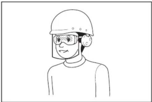
a 1 a 1 a 1 a 1 a 1 a 1 a 1 a 1 a 1 a 1 a 1 a 1 a 1 a 1 a 1 a 1 a 1 a 1 a 1 a 1 a 1 a 1 a 1 a 1 a 1 a 1 a 1 a 1 a 1 a 1 a 1 a 1 a 1 a 1 a
J 1
J 1
J 1
J 1
J 1
J 1
J 1
J 1
J 1
Jg 3
yR S 0
yR S 1
yR S 2
yR S 3
yR S 4
yR S 5
Lai 5
Jiau u jia u Jiau u Jiau u Jiau u Jiau u Jiau u Jiau u Jiau u Jiau u Jiau u Jiau u Jiau u Jiau u Jiau u Jiau u Jiau u Jiau u Jiau u Jiau u Jiau u Jiau u Jiau u Jiau u Jiau u Jiau u Jiau u Jia
y
Lgall
| : : | ||
| 320 mm | BL4025 | الإستعمال |
| BL4040 | 36 mm | |
| ... | ... | |
| ... | ... | ... |
| ... | ... | ... |
| ... | ... | |
j 1
EPTA-Procedure 01/2014 111111111111111111111111111111111111
Jg
Jaiyllal
| BL4050F / BL4040 / BL4025 / BL4020 | سیدعَبْلَبْرْيرِ |
| DC40RC / DC40RB / DC40RA | الشامن |
.5jai 1sly 1sli ai jia lai laoi jia jia
jia jieill gai jieill cui jieill (a) aai iaii li jy
1
:
oiiei jaiinjui iuii ieigaiiei iiai:
y j 1000
a a a a a a a a a a a a a a a a a a a

- Applicable battery cartridge and charger
- Symbols
- Intended use
- Noise
- Vibration
- EC Declaration of Conformity
- For European countries only
- SAFETYWARNINGS
- General power tool safety warnings
- Save all warnings and instructions for future reference.
- Work area safety
- Electrical safety
- Personal safety
- Power tool use and care
- Battery tool use and care
- Service
- Cordless inflator safety warnings
- Important safety instructions for battery cartridge
- SAVE THESE INSTRUCTIONS.
- Tips for maintaining maximum battery life
- FUNCTIONAL DESCRIPTION
- Installing or removing battery cartridge
- Indicating the remaining battery capacity
- Tool / battery protection system
- Overload protection
- Overheat protection
- Overdischarge protection
- Main power switch
- Switch action
- Pressure gauge
- Setting the target pressure value
- Setting the inflation mode
- Lighting up the front lamp
- Storing adapter
- Storing hose
- Air release button
- OPERATION
- Using the English valve adapter
- Using the Schrader valve adapter
- Using the Presta valve adapter
- Using the sport ball needle
- Using the tapered adapter
- MAINTENANCE
- OPTIONAL ACCESSORIES
- ACCESSIONS EN OPTION
- VEILIGHEIDSWAARSCHUWINGEN
- OPTIONELE ACCESSOIRES
- Sikkerhedsadvarsler for akku pumpe
- Simboli
- TIETO POKNY USCHOVAJTE.
- 3ana3eTe BCnUKN ppeDynpexKeHnI INHCTpyKcnn 3a cnpabKa B6bndeue.
- E30nachocBpa6oTHata 30Ha
- EneKtpnuecka 6e3onacHocT
- JinuHa 6e3oNaCHOCT
- IOn3BaHe n rpnKn 3a eNeKtpnuecknte HNCTpyMeHTn
- Ioi3BaHe n rpnka 3a akymylatopnhte 6aTeepn
- CepBn3Ho 06cnyXBaHe
- IpeDynpexKeHnna 3a 6e30nacHocT 3a akymlyaTopnna KOMnPecop
- BaxHHN HnCTpyKcHn 3a 6e30NaChOcT 3a akymyIaTopHaTa 6aTepeHra
- 3A7A3ETE HACTOUINTEHCHPKUH.
- CbBeTn 3a nOdIbPjXaHe Ha MaKcImaJIHo IbJIbI JxIBOT Ha aKyMyJatOpHnTe 6aTeepn
- Опиcaне HAФУнкцИNTE
- NocTabrHe N3BaxdaHe Ha akymyIaTOPHaTa 6aTePnA
- Hdkaun Ha octaBaun KaanTeHa akymyntopHaTa 6aTePn
- 3aDaBaHe Ha ueBbTa CToHocT Ha HalaRaHeTo
- 3aandaBaHe Ha peXIM HaHaNyBaHe
- ДОПьнHTЕЛНИAKCECOAPN
- PONDPbJXKA
- CknpaHpaHbe Ha UpeBOTO
- Konue 3a OTnyuTaHbe Ha BO3dyXoT
- PABOTEHe
- KopncTeBe Ha aanTepoT 3a aHnCKNt BEHTIJI
- KopncTeHbe Ha aDanTepot 3a amepnKaHcN (wpaep) BeHTNJ
- Bibpaçia
- Ieknapaia npo BiAnobiHicTb cTaHdaptam EC
- BnKOpncTaHnTa o6cnyroByBaHHaKymyIaTOpHX iHCTpyMeHTiB
- 06cnyroByaHHa
- 3axoNi 6e3neKn NiJ qac BnKOpNCtAHNHa kUyMylrTOphoro Hacoca
- BaxnBi iHcTpykci3 6e3neKn dny kacetn 3 akymyIaTOPoM
- 3БЕPIГАNTE LIBKA3IBKN.
- Iopadn 3 3a6e3neueHnMaKcNmAlbHorO cTpOKy ekCnJyaTauciiakymyIaTopa
- ONMCPOBOTN
- BcTaHOBJIeHHa Ta 3HЯTTKaCeTu 3 akymyIaTOPoM
- BidobpaXeHHaNnKoBOrO 3apAdy aKymyIaTopa
- 3axnt BiD nepeBaHTaXeHHN
- 3axnct BiD neperpiBaHHa
- 3axnct BiD haMipHoro po3pIKeHn
- TOLOBHn BmMkaq XNBJIeHHA
- Дя Вимнкача
- MaHometp
- YcTaHOBka 3aHaHOro 3HaueHnTnCKy
- YcTaHOBJIeHHpeKIMyHaKaUyBaHHa
- OBEPEXHO: He duBtbcra ha cBtno a6o 6e3nocepndbo Ha dKepeNo Cbitna.
- 36epirahnna nepexiDnkiB
- 36epiraHnHaHaHra
- Khonka Bnnycky nobitpy
- POBOTA
- BnKopncTaHnI nepexIDnka dIaHrniIcbKOro KnaanaHa
- BnKopncTaHnI nepeXidHnka dIy Klaanaha Upaepa
- BukopncTaHnpepeXiDnkaДля Knanana Presta
- BukopncTaHHraonKn dna cnoptnBnX m'ayib
- BukopncTaHnKa KOiHyOro nepexiDnka
- TEXHlYHE OBCJlyrOByBAHHa
- ДОДАТКОВЕ ПИЛАДЯ
- Bn6paun
- Декларацяо COOTBETCTBUN EC
- MEPbI BE3OПACHOCTN
- Obuzne pekomeHdaunno TeXnke 6e3oNaCHOCTn dny 3JIeKTPoHHCTpyMeHTOB
- CoxpaHnte 6pOshOpy c nHcTpyK- CnIaMn I peKoMeHdaZnAMyN dJa DaJIbHeIWeRo NcNoIb3OBaHnY.
- JnHna 6e3onacHOCTb
- 3KcnIyataunn no6cnykBaHne 3NeKtpoHHCTpyMeHTa
- 3Kcnnyataunn no6cnykubAHne 3NeKTpOHcTpyMeHTa,pa6oTaOooRoHaakymyIaTopax
- CepBnchoe 6cbnykBaHne
- MepbI 6e3oNaChocTn npn nCNoJIb3OBAHnN aKKyMylrTOpHOro Hacoca
- BaxHbIe npaBnla TexHnKn 6e3oNaChOCTn,Ira pa6Otbl C aKKyMylTOpHbIM 6JOKOM
- COXPAHNTE DAHHbIE NHCTPYKcN.
- CobetbI NO obecneueHIO maKcHMaJIbHO r cPoka cIyX6blaKKymyIaTopa
- ОпИСАне PAБOTыI
- YcTaHOBka NJIncHrTne 6JOKa aKKyMylrTopoB
- HdkaocnOCTaBweroC3apJa aKKymyTopa
- TnaBbI nepeKIOuateJeNtTaHnA
- DeyCTBnE BbIKIOyateTJe
- YCTaHOBka 3aDaHHoro 3HaueHnnaDabJIeHnA
- YcTaHOBkapeXIMHaKaUBaHnA
- DaHeHne IepexOdHnKOB
- baheHHe uHaHra
- IcnoIb3OBAHne KOHNueCKORo nepexoDnka
- A BHUMAHNE: He donyckaIte ype3MepHoro HakaunhaHn Tpy6 dnn nlaBaHn.
- Benrinep
- KoIaHy MaKcaTbI
- Wy
- Dipin
- Xymbic aimarbiHdaraikayinci3ik
- 3neKtpnik kayinci3ik
- KekeKayinci3ik
- 3neKtpnik Kypandbi naDanaHy XHe KyTIM Xacay
- AkkymyIaTOPMeH KymbIc icTeuTIN KypaIbI naIaIaNy XeHe KytIM Xacay
- Kb3MeT Kepcety
- AkkymyTopnbI copfbicbIHkayinci3diri 6oBbHwa eckeptynep
- AkkymyITop KapTpndxHe apHaIFaH MaHbI3dbl KayiNci3dk HycKaynapbl
- AkkymyIaTOPdbIH MaKcIMaIdbI Kbl3MeT eTy MEP3iMH caKtay 6oYbIHwa KeHeCTep
- ФУнкционалдыКСИПATTAMACbl
- AkkymyIaTOp KapTpIaXiH opHaTy Hemece any
- AkkymyIaTOpIbIH KaJIFaH KyaTbIH KepceTy
- KypaIbIH/aKKyMnyTOpDbIH KopFaHbIC Kyyneci
- Uamadan TbIC KyKTeMeDeH KopraHbIC
- KbI3bIn KeTyDeH KopFaHbIC
- 3apTbIn 7aMaHaN TbIC TaycbIybiHaH KopFaHbIC
- Bactbkyataybictbipbin-Kockbiwbl
- AybicTbipbn-KockblwTbIH apekeTi
- MaKcaTbI KbICbIM mHiH oPhAty
- Ypney pexmih ophaTy
- Andbihfbi waMdbi XapbIKTaHdbipy
- AanTepdi caKtay
- Uanrhi caTay
- AyaHBI 6ocaty Tymeci
- ПАДАЛAHY
- AfbIiBbIHbIH KnaH aAnTepiH naJaHaHy
- TEXHINKAJIbIK Kbl3MET KOPCETY
- KOCbIMWA KEPEK-JKAPAKTAP
- s
- EC
- Sla
- y
- 4aJgSgJrLa glaJdA
- liny plao gao
- 24jzll 24
- = ( 10 - 1) ÷ 20 = - 8( 5)
- Ail
- p
- 1gj
- #
- .
- i
- yjbnllgddia aolla oolwclal
- Lgall
- Jaiyllal
Brand : MAKITA
Model : MP001G
Category : Compressor