
GTC 400 C Professional - Camera BOSCH - Free user manual and instructions
Find the device manual for free GTC 400 C Professional BOSCH in PDF.
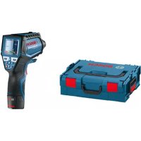
| Product type | Thermal camera |
| Brand | Bosch |
| Model | GTC 400 C Professional |
| Infrared sensor resolution | 160 x 120 pixels |
| Thermal sensitivity | < 50 mK |
| Temperature measurement range | -10 °C to +400 °C |
| Measurement accuracy (typical) | ±3 °C (from -10 to +100 °C); ±3 % (>+100 °C) |
| Field of view (FOV) | 53 x 43° |
| Display | TFT color 3.5", resolution 320 x 240 |
| Internal memory | 500 images (JPG format) |
| Power supply | 4 AA batteries (LR6) or Li-Ion rechargeable battery 10.8/12 V |
| Battery life | 2 h (batteries) / 5 h (rechargeable) |
| Connectivity | WiFi, Bluetooth 4.2, port micro-USB 1.1 |
| Dimensions (L x W x H) | 233 x 95 x 63 mm |
| Weight | 0.54 kg |
| Protection rating | IP 53 |
| Integrated visual camera | Yes |
| Measurement functions | Hot/cold spot detection, real image overlay, color palettes |
| Maintenance | Clean with a dry cloth; do not use sharp objects on the lens |
| Safety | Do not use in explosive atmospheres; remove battery before maintenance |
| After-sales service | Bosch; repair by qualified personnel using original parts |
Frequently Asked Questions - GTC 400 C Professional BOSCH
User questions about GTC 400 C Professional BOSCH
0 question about this device. Answer the ones you know or ask your own.
Ask a new question about this device
Download the instructions for your Camera in PDF format for free! Find your manual GTC 400 C Professional - BOSCH and take your electronic device back in hand. On this page are published all the documents necessary for the use of your device. GTC 400 C Professional by BOSCH.
USER MANUAL GTC 400 C Professional BOSCH
ORJ BIUCTL-3136-002.hook Page 1 Tuesday, August 22, 2017 6:25 PM
natural_image
Exterior view of a Bosch handheld device (no visible text or symbols)Robert Bosch Power Tools GmbH
70538 Stuttgart
GERMANY
www.bosch-pt.com
1609 92A 3RD (2017.08) T/322
GTC 400 C Professional

BOSCH
natural_image
Line drawing of a Bosch electric shaver with no text or symbolsAL 1115 CV GAL 1215 CV
natural_image
Line drawing of a steam iron with ventilation slots and handle (no text or symbols)AL 1130 CV GAL 1230 CV
AA1 1608 M00 C1B
natural_image
Illustration of a USB cable with a connector, labeled with number 24 (no text or symbols on the cable itself)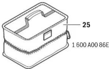
5
1 609 92A 3RD | (22.8.17) Bosch Power Tools
6 | Deutsch
Deutsch
Sicherheitshinweise

Available on the App Store

GET IT ON Google Play
Read and observe all instructions. The integrated protections in the measuring tool may be compromised if the measuring tool is not used in accordance with the instructions provided. SAVE THESE INSTRUCTIONS FOR FUTURE REFERENCE.
▶ Have the measuring tool repaired only through qualified specialists using original spare parts. This ensures that the safety of the measuring tool is maintained.
▶ Do not operate the measuring tool in explosive environments, such as in the presence of flammable liquids, gases or dusts. Sparks can be created in the measuring tool which may ignite the dust or fumes.
Before any work on the measuring tool itself (e.g. assembling, maintenance, etc.) as well as when transporting and storing, remove the battery pack or the batteries from the measuring tool.
▶ Do not open the battery pack. Danger of short-circuiting.

Protect the battery pack against heat, e.g., against continuous intense sunlight, fire, water, and moisture. Danger of explosion.
When battery pack is not in use, keep it away from other metal objects like paper clips, coins, keys, nails, screws, or other small metal objects that can make a connection from one terminal to another. Shorting the battery terminals together may cause burns or a fire.
▶ Under abusive conditions, liquid may be ejected from the battery pack; avoid contact. If contact accidentally occurs, flush with water. If liquid contacts eyes, additionally seek medical help. Liquid ejected from the battery pack may cause irritations or burns.
In case of damage and improper use of the battery pack, vapours may be emitted. Provide for fresh air and seek medical help in case of complaints. The vapours can irritate the respiratory system.
▶ Recharge only with the charger specified by the manufacturer. A charger that is suitable for one type of battery pack may create a risk of fire when used with another battery pack.
▶ Use the battery pack only in conjunction with your Bosch measuring tool. This measure alone protects the battery pack against dangerous overload.
The battery pack can be damaged by pointed objects such as nails or screwdrivers or by force applied externally. An internal short circuit can occur and the battery pack can burn, smoke, explode or overheat.
The non-rechargeable battery adapter is intended only for use in designated Bosch measuring tools and must not be used with power tools.
Remove the batteries from the measuring tool when not using it for extended periods. When storing for extended periods, the batteries can corrode and self-discharge.
▶ Protect the measuring tool, particularly the area around the camera and infrared lens, against moisture and snow. The reception lens could fog up and distort the measurements. Incorrect settings on the tool and other atmospheric influences may make the measurements inaccurate. Objects could be depicted hotter or colder, which may present a danger if touched.
▶ High temperature differences in a thermal image may cause even high temperatures to be shown in a colour associated with low temperatures. Coming into contact with such an area may cause burns.
▶ Temperature measurements will only be correct if the emissivity setting and the emissivity of the object match. Objects could be depicted hotter or colder in temperature and/or colour, which may present a danger if touched.
Caution! When using the measuring tool with Bluetooth®, interference with other devices and systems, airplanes and medical devices (e.g., cardiac pacemakers, hearing aids) may occur. Also, the possibility of humans and animals in direct vicinity being harmed cannot be completely excluded. Do not use the measuring tool with Bluetooth® in the vicinity of medical devices, petrol stations, chemical plants, areas where there is danger of explosion, and areas subject to blasting. Do not use the measuring tool with Bluetooth® in airplanes. Avoid operation in direct vicinity of the body over longer periods.
The measuring tool is equipped with a radio interface. Local operating restrictions, e.g. in airplanes or hospitals, are to be observed.


English | 17
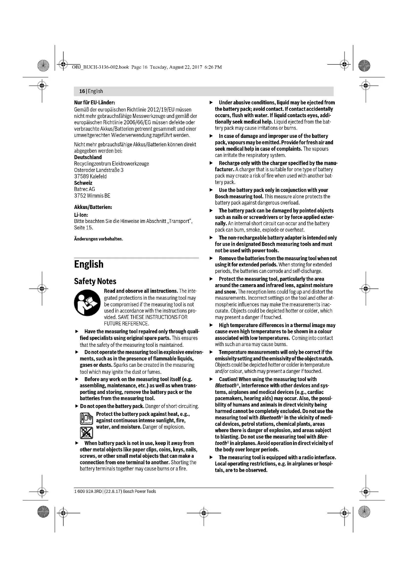
Product Description and Specifications
Please unfold the fold-out page with the representation of the measuring tool and leave it unfolded while reading the operating instructions.
The Bluetooth ^® word mark and logos are registered trademarks owned by Bluetooth SIG, Inc. and any use of such marks by Robert Bosch Power Tools GmbH is under licence.
Intended Use
This thermal imaging camera is designed for the contactless measurement of surface temperatures.
The displayed thermal image shows the temperature distribution of the area captured by the infrared lens and therefore enables temperature deviations to be depicted in different colours.
When used correctly, this makes it possible to examine areas and objects in a contactless manner for temperature differences and discrepancies in order to make components and/or any weaknesses visible, including:
– Thermal insulation and other types of insulation (e.g. locating thermal bridges)
- Active heating and hot water pipes (e.g. underfloor heating) in floors and walls
- Overheated electrical components (e.g. fuses or terminals)
- Machine parts (e.g. overheating due to faulty ball bearings)
The measuring tool must not be used for temperature measurement on persons and animals or for other medical purposes.
The measuring tool is not suitable for surface temperature measurement of gases or liquids.
Product Features
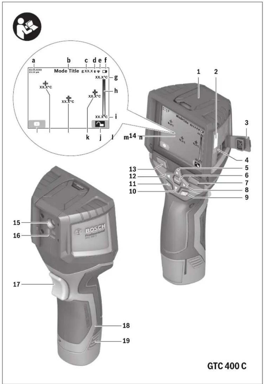
The numbering of the product features shown refers to the illustration of the measuring tool on the graphic page.
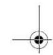
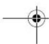
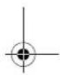
1 Protective cap for visual camera and infrared sensor
2 Serial number
3 Cover, micro USB port
4 Micro USB port
5 Up arrow button
6 "Func" measuring functions button
7 Switching temperature scale between automatic and fixed/right-hand function button
8 Right-hand arrow button
9 On/Off button
10 Down arrow button
11 Save button
12 Left-hand arrow button
13 Gallery button/left-hand function button
14 Display
15 Visual camera
16 Infrared sensor area
17 Freeze measurement/continue measuring button
18 Battery port
19 Release button for battery pack/battery adapter
20 Battery adapter sealing cap*
21 AA battery adapter cover*
22 Cover recess
23 Battery pack*
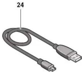
24 Micro USB cable
25 Protective pouch*
* The accessories illustrated or described are not included as standard delivery.
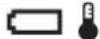
Display Elements
a Date/time
b Measuring function
c Emissivity display
d Indicator for Bluetooth® connection
e WiFi switched on/off indicator
f Charge-control indicator
g Display of maximum surface temperature in the measurement range
h Scale
i Display of minimum surface temperature in the measurement range
j Scale lock symbol
k Hotspot display (example)
I Crosshairs with temperature display
m Coldspot display (example)
n Gallery symbol
Technical Data
| Thermal imaging camera GTC 400 C | |
| Article number | 3 601 K83 1.. |
| Resolution of infrared sensor | 160 x 120 |
| Thermal sensitivity | <50mK |
| Spectral range | 8-14μm |
| Field of view (FOV) | 53 x 43° |
The measuring tool can be clearly identified with the serial number 2 on the type plate.
1) at an ambient temperature of 20–23 °C and an emissivity of >0.999, measuring distance: 0.3 m, operating time: >5 min
2) limited performance at temperatures <0 °C
Technical data determined with battery from delivery scope.


18 | English
| Thermal imaging camera GTC 400 C | |
| Focus distance ≥0.3m | |
| Focus | Fixed |
| Surface temperature measurement range | -10...+400 °C |
| Measuring accuracy (typical) | |
| Surface temperature^1) | |
| -10...+10 °C | ±3°C |
| 10...100 °C | ±3°C |
| >+100 °C | ±3% |
| Display type | TFT |
| Display size | 3.5" |
| Display resolution | 320 x 240 |
| Image format | .jpg |
| Images saved per saving process | 1 x thermal image (screenshot)1 x real visual image incl. temperature values (metadata) |
| Number of images in internal image memory (typical) | 500 |
| Integrated visual camera | ● |
| Batteries (alkali-manganese) | 4 x 1.5 V LR6 (AA) (with battery adapter) |
| Battery pack (lithium-ion) | 10.8 V/12 V |
| Battery life | |
| -Batteries (alkali-manganese) | 2.0 h |
| -Battery pack (lithium-ion) | 5.0 h |
| USB port | 1.1 |
| TrackMyTools Bluetooth® module power supply | |
| -Button cell | CR2450 (3 V lithium battery) |
| -Battery service life, approx. | 60 months |
| Bluetooth® | Bluetooth® 4.2 (Low Energy) |
| Max. Bluetooth® transmission power | 3.2 mW |
| Frequency band Bluetooth® | 2.402 -2.480 GHz |
| Wireless connectivity | WiFi |
| Max. WiFi transmission power | 30 mW |
| WiFi operating frequency range | 2.400-2.483 GHz |
| Weight according to EPTA-Procedure 01:2014 | 0.54 kg |
| Dimensions (length x width x height) | 233 x 95 x 63 mm |
| Degree of protection (excluding battery compartment) | IP 53 |
| Permitted environmental conditions | |
| -Charging temperature | 0...+45 °C |
| -Operating temperature | -10...+45 °C |
| -Storagetemperature | -20...+70 °C |
| -Relative humidity (non-condensing) | 20...80% |
| Recommended batteries | GBA 10,8 VGBA 12 V |
| Recommended chargers | AL 11..CVGAL 12..CV |
The measuring tool can be clearly identified with the serial number 2 on the type plate.
1) at an ambient temperature of 20–23 °C and an emissivity of >0.999, measuring distance: 0.3 m, operating time: >5 min
2) limited performance at temperatures <0 °C
Technical data determined with battery from delivery scope.
English | 19
Assembly
Power Supply
The measuring tool can be operated using either commercially available batteries (LR6 AA batteries or similar) or using a Bosch Li-ion rechargeable battery.
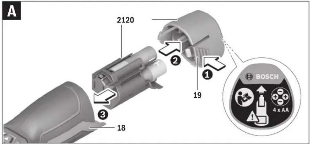
Operation with Battery Adapter (Removable) (see figure A)
The batteries are inserted into the battery adapter.
The non-rechargeable battery adapter is intended only for use in designated Bosch measuring tools and must not be used with power tools.
To insert the batteries, slide the cover of the battery adapter 21 into the battery port 18. Place the batteries in the cover as per the illustration on the sealing cap 20. Slide the sealing cap over the cover until you feel it click into place and it is flush with the handle of the measuring tool.

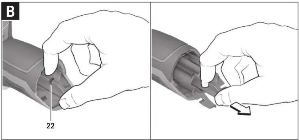
To remove the batteries, press the release buttons 19 of the sealing cap 20 and pull off the sealing cap. In doing so, make sure that the batteries do not fall out. To do this, hold the measuring tool with the battery port 18 facing upwards. Remove the batteries. To remove the inside cover 21 from the
battery port 18, reach into the cover recess 22 and pull it out of the measuring tool by applying light pressure to the side wall (see figure B).
Note: Do not use any tools (e.g. a screwdriver) to remove the battery, as this could break the casing.
Always replace all batteries at the same time. Only use batteries from one brand and with the identical capacity.
Remove the batteries from the measuring tool when not using it for extended periods. When storing for extended periods, the batteries can corrode and self-discharge.
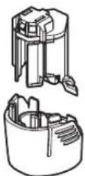
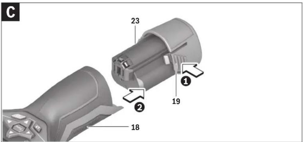
Operation with Battery Pack (see figure C)
Note: Use of battery packs not suitable for the measuring tool can lead to malfunctions of or cause damage to the measuring tool.
Note: The battery pack is supplied partially charged. To ensure full capacity of the battery pack, completely charge the battery pack in the battery charger before using for the first time.
▶ Use only the chargers listed in the technical data. Only these battery chargers are matched to the lithium-ion battery of your measuring tool.
The lithium-ion battery pack can be charged at any time without reducing its service life. Interrupting the charging procedure does not damage the battery pack.
▶ Following the automatic shut off of the measuring tool, do not continue to press the On/Off button. The battery can be damaged.
To insert the charged battery pack 23, slide it into the battery port 18 until you feel it engage and it is flush with the handle of the measuring tool.
To remove the battery pack 23, press the unlocking buttons 19 and pull the battery pack out of the battery port 18. Do not use force to do this.
Battery Status Indicator
The battery status indicator f on the display shows the charging state of the batteries or battery pack 23.
| Indication Capacity | |
| >2/3 | |
| ≤2/3 | |
| ≤1/3 | |
| ≤10% | |
| Changing the Batteries or Battery Pack | |
Operation
▶ Protect the measuring tool against moisture and direct sun light.
Do not subject the measuring tool to extreme temperatures or variations in temperature. As an example, do not leave it in vehicles for a long time. In case of large variations in temperature, allow the measuring tool to adjust to the ambient temperature before putting it into operation. In case of extreme temperatures or variations in temperature, the accuracy of the measuring tool can be impaired.
▶ Make sure that the measuring tool is correctly acclimatised. In the event of severe temperature fluctuations or environmental conditions which vary to a large degree, the measurement accuracy of the measuring tool may be impaired until it is fully acclimatised again.
▶ Avoid hard knocks to the measuring tool or dropping it.
After severe external influences and in the event of abnormalities in the functionality, you should have the measuring tool checked by an authorised Bosch after-sales service agent.
Initial Operation
Switching On and Off
To take a measurement, fold the protective cap 1 upwards. Make sure that the infrared measuring area is not closed off or covered while working.
To switch on the measuring tool, press the On/Off button 9. A start sequence will appear in the display 14. After the start sequence, the measuring tool will immediately begin to measure and will measure continuously until it is switched off.
Note: In the first few minutes, the measuring tool may self-calibrate several times, as the sensor temperature and ambient temperature have not yet been brought into line. Performing calibration again enables precise measurement. The thermal image freezes briefly during calibration.
To switch off the measuring tool, press the On/Off button again. The measuring tool saves all settings and then switches itself off. Close the protective cap 1 to transport the measuring tool safely.
20 | English
In the "Settings" menu, you can choose whether and after how much time the measuring tool automatically switches off (see "Switch-off time", page 22).
If the battery or the measuring tool is not within the operating temperature range stated in the Technical Data, the measuring tool will shut down automatically after a brief warning (see "Troubleshooting – Causes and Corrective Measures", page 23). Allow the measuring tool to reach to the correct temperature and then switch it back on.
To save energy, only switch the measuring tool on when you are using it.
Preparing for Measurement
Setting the Emissivity Degree for Surface-temperature Measurements
The emissivity degree of an object depends on the material and the structure of its surface. It indicates whether an object (in comparison with other objects with the same temperature) emits much or little infrared heat radiation.
To determine the surface temperature, the tool performs a contactless measurement of the natural infrared thermal radiation emitted by the object at which the tool is aimed. To ensure correct measurement, the emissivity setting on the measuring tool must be checked before every measurement and adapted to the measuring object if necessary.
You can select one of the preset emissivity levels or enter an exact numerical value. Adjust the required emissivity using the "Measurement" > "Emissivity" menu (see page 21).
▶ Temperature measurements will only be correct if the emissivity setting and the emissivity of the object match.
Differences in colour may be caused by different temperatures and/or different emissivity levels. If the emissivity levels are very different, the depicted temperature differences may differ considerably from the actual temperature differences. If there are multiple objects made of different materials or that have different structures in the measurement range, the displayed temperature values are only conclusive for the objects that match the emissivity setting. For all other objects (with different emissivity levels), the displayed colour differences can be used as an indication of temperature relationships.
Material Emissivity
(reference value 0 °C to 100 °C)
| Concrete 0.93 |
| Plaster/mortar 0.93 |
| Roofing tiles 0.93 |
| Roofing felt 0.93 |
| Radiator paint 0.93 |
| Wood 0.91 |
| Linoleum 0.88 |
| Paper 0.89 |
Notes on the Measuring Conditions
Highly reflective or shiny surfaces (e.g. shiny tiles or polished metals) may distort or impair the results shown. If necessary, mask the surface to be measured with a dark, matt adhesive tape that conducts heat well. Allow the tape to acclimatise briefly on the surface.
Make sure that a favourable measuring angle is used on reflective surfaces in order to ensure that the thermal radiation reflected by other objects does not distort the result. For example, the reflection of your own body heat may interfere with the measurement when measuring head-on from a perpendicular position. On a level surface, the outline and temperature of your body could therefore be displayed (reflected value), and these values do not correspond to the actual temperature of the measured surface (emitted value or real value of the surface). Measuring through transparent materials (e.g. glass or transparent plastics) is fundamentally not possible.
The accuracy and reliability of the measuring results increase with better and more stable measuring conditions.
Infrared temperature measurement is impaired by smoke, vapour/high air humidity or dusty air.
Information for achieving improved measurement accuracy:
- Get as close as possible to the measuring object to minimise interfering factors between you and the surface to be measured.
- Ventilate indoor areas prior to measurement, especially when the air is contaminated or extremely steamy. After ventilating, allow the room to acclimatize for a while until the usual temperature has been reached again.
Assigning temperatures on the basis of the scale
A scale is shown on the right-hand side of the display. The values at the top and bottom end are oriented to the maximum and minimum temperature recorded in the thermal image. Colours are assigned to temperature values with a uniform distribution in the image (linearly).
Different shades can therefore be used to assign temperatures within these two limit values. For example, a temperature that is exactly between the maximum and minimum value can be assigned to the centre colour range of the scale.
To determine the temperature of a specific area, move the measuring tool so that the crosshairs with temperature display I are aimed at the required point or area.
In the automatic setting, the colour spectrum of the scale is always distributed linearly (= uniformly) across the entire measurement range between the maximum and minimum temperatures.
The thermal imaging camera displays all measured temperatures in the measurement range in relation to one another. If heat is displayed as blue in the colour palette in an area, for example in a colour representation, this means that the blue areas are among the colder measured values in the current measurement range. However, these areas may be in a temperature range that could cause injuries in certain circumstances. You should therefore always note the temperatures displayed on the scale or at the crosshairs themselves.


English | 21
Functions
Adjusting the colour display
Depending on the measurement conditions, different colour palettes can make it easier to analyse the thermal image and show objects or circumstances more clearly in the display. This does not affect the measured temperatures. Only the way in which the temperature values are shown changes.
To change the colour palette, remain in measuring mode and press the right-hand 8 or left-hand 12 arrow button.
Superimposition of thermal image and real image
For improved orientation (= local assignment of the thermal image displayed), with matched temperature ranges, a visual real image can additionally be inserted.
Note: The superimposition of the real image and thermal image is accurate at a distance of 0.55 m. If the tool is closer to or further away from the object being measured, this may result in misalignment of the real image and thermal image.
The thermal imaging camera offers you the following options:
- Complete infrared image
Only the thermal image is displayed.
- Image in image
The thermal image displayed is cropped and the surrounding area is shown as a real image. This setting improves the local assignment of the measurement range.
- Transparency
The thermal image displayed is placed on top of the real image in such a way that it is slightly transparent. This enables improved detection of objects.
You can adjust the setting by pressing the up 5 or down 10 arrow buttons.
Fixing the scale
The colour distribution in the thermal image is adjusted automatically but can be fixed by pressing the right-hand function button 7. This enables a comparison to be made between thermal images taken under different temperature conditions (e.g. when checking several rooms for thermal bridges).
To switch the scale back to automatic, press the right-hand function button 7 again. The temperatures are now dynamic again and adapt to the measured minimum and maximum values.
Measuring functions
To call up further functions which may be helpful for the display, press the "Func" button 6. Use the right-hand/left-hand buttons to navigate through the displayed options to select a function. Select a function and press the "Func" button 6 again.
The following measuring functions are available:
"Automatic"
Colours are distributed automatically in the thermal image
- "Heat detector"
Only the warmer temperatures in the measurement range are displayed as a thermal image in this measuring function. The area outside these warmer temperatures is dis-
played in greyscale as a real image so that coloured objects are not wrongly associated with temperatures (e.g. red cable in the control cabinet when looking for overheated components). Adjust the scale using the up 5 and down 10 buttons. This expands or reduces the temperature range shown.
The tool continues to measure minimum and maximum temperatures and displays these at the ends of the scale. You can, however, control which temperature range is shown in colour as a thermal image.
- "Cold detector"
Only the colder temperatures in the measurement range are displayed as a thermal image in this measuring function. The area outside these colder temperatures is displayed in greyscale as a real image so that coloured objects are not wrongly associated with temperatures (e.g. blue window frame when looking for faulty insulation). Adjust the scale using the up 5 and down 10 buttons. This expands or reduces the temperature range shown. The tool continues to measure minimum and maximum temperatures and displays these at the ends of the scale. You can, however, control which temperature range is shown in colour as a thermal image.
- "Manual"
If greatly deviating temperatures are measured in the thermal image (e.g. radiator as a hot object when searching for thermal bridges), the available colours are distributed among a large number of temperature values in the range between the maximum and the minimum temperature. This can result in a situation where subtle temperature differences can no longer be shown in detail. To obtain a detailed depiction of the focus temperature, switch to "Manual" mode and set the maximum and the minimum temperature. Doing this enables you to set the temperature range that is relevant to you and in which you would like to detect subtle differences. The Reset setting automatically readjusts the scale to the measured values in the infrared sensor's field of view.
Main Menu
To access the main menu, press the "Func" button 6 to call up the measuring functions. Now press the right-hand function button 7.
- "Measurement"
- "Emissivity" c:
A selection of saved emissivity levels is available for some of the most common materials. Select the appropriate material in the "Material" menu item. The corresponding emissivity is displayed in the line below. If you know the exact emissivity of the object to be measured, you can also set it as a numerical value in the "Emissivity" menu item.
- "Reflected temperature":
Setting this parameter improves the accuracy of measuring results, especially with low-emissivity (= high-reflection) materials. The reflected temperature normally corresponds to the ambient temperature.
If there are objects with greatly deviating temperatures close to highly reflective objects which could affect the measurement, this value should be adjusted.


22 | English
- "Display"
- "Hotspot" k: "ON/OFF"
In this function, the hottest point (= measuring pixel) in the measurement range is automatically highlighted by red crosshairs in the thermal image. This can help you to detect a critical point, e.g. to locate a loose terminal in the control cabinet.
- "Cold spot" m: "ON/OFF"
The coldest point (= measuring pixel) in the measurement range is automatically highlighted by blue cross-hairs in the thermal image. This can help you to detect a critical point, e.g. to locate a leak in insulation.
- "Crosshairs" I: "ON/OFF"
The crosshairs are displayed in the centre of the thermal image and show you the measured temperature value at this point.
- "Scale" h: "ON/OFF"
- "WiFi": "ON/OFF"
(see "Data Transmission", page 22)
- "Track My Tools": "ON/OFF"
(see "TrackMyTools", page 24)
- "Tool"
- "Language"
Under this menu item, you can change the language for all displays.
- "Time & Date" a
To change the date and time in the display, open the "Time & Date" submenu. In this submenu you can also change the date and time format.
To exit the "Time & Date" submenu, press either the left-hand function button 13 under the tick symbol to save the settings or the right-hand function button 7 under the cross symbol to discard the changes.
- "Audio signals": "ON/OFF"
Under this menu item, you can switch the audio signals on or off.
- "Switch-off time"
Under this menu item, you can select the time interval after which the measuring tool will automatically switch off if no buttons are pressed. You can also deactivate the automatic switch-off by selecting the "Never" setting.
- "Delete all images"
Under this menu item, you can delete all the files in the internal memory at once. Press the right-hand arrow button 8 for "more ..." to enter the submenu. Then press either the left-hand function button 13 under the tick symbol to delete all files, or the right-hand function button 7 under the cross symbol to cancel the operation.
- "Tool information"
Under this menu item, you can access information about the measuring tool. There you can find the serial number of the measuring tool and the installed software version.
You can also press button 17 to exit any menu and return to the standard display screen.
Documenting measurements
Saving measurements
The measuring tool begins to take measurements as soon as it is switched on and does so continuously until it is switched off.
To save an image, point the camera at the desired measuring object and press the "Save" button 11. The image is saved in the camera's internal memory. Alternatively, press the
"Freeze measurement" button 17. The measurement is frozen and shown in the display. This enables you to take as much time as you need to look at the image. If you do not wish to save the frozen image, press button 17 to return to measuring mode. If you wish to save the image in the camera's internal memory, press the "Save" button 11.
Calling up saved images
Proceed as follows to call up saved thermal images:
- Press the left-hand function button 13. The most recently saved photo now appears in the display.
- Press the right-hand 8 or left-hand 12 arrow button to switch between the saved thermal images.
Deleting saved images
Go to the gallery view to delete individual thermal images:
- Press the right-hand function button 7 under the waste paper basket symbol.
- Confirm the operation by pressing the left-hand function button 13 or terminate the deletion process by pressing the right-hand function button 7 under the cancel symbol.
Delete all images
In the "Delete all images" menu, you can delete all the files in the internal memory at once.
Press the "Func" 6 button to call up the measuring functions. Now press the right-hand function button 7 and select
"Tool" > "Delete all images". Press the right-hand arrow button 8 to enter the submenu. Then press either the left-hand function button 13 under the tick symbol to delete all files, or the right-hand function button 7 under the cross symbol to cancel the operation.
Data Transmission
Data Transmission via USB Interface
Open the cover on the micro USB port 3. Connect the micro USB port on the measuring tool to your PC or laptop using the micro USB cable provided.
Now press button 9 to switch on the thermal imaging camera. Open the file browser and select the "BOSCH GTC 400 C" drive. The saved JPG files can be copied, moved to your computer or deleted from the internal memory of the measuring tool.
As soon as you have ended the required operation, disconnect the drive following the standard procedure and then use button 9 to switch the thermal imaging camera off again.
Remove the micro USB cable during the measurement operation and close the cover 3.


Attention: Always disconnect the drive from your operating system first (eject drive), as failure to do so may damage the thermal imaging camera's internal memory.
Always keep the cover of the USB interface closed so that dust and splashes cannot enter the housing.
Note: Only connect the measuring tool to a PC or notebook. The tool could be damaged if you connect it to a different device.
Note: The micro USB interface can only be used for data transmission – it is not suitable for charging batteries.
Post-editing the thermal images
You can post-edit the saved thermal images on your computer if it uses a Windows operating system. To do so, download the GTC Transfer software from the product page for the thermal imaging camera at
www.bosch-professional.com/gtc.
Data transmission via WiFi
The measuring tool is equipped with a WiFi module which enables the saved images to be wirelessly transmitted from your thermal imaging camera to a mobile device.
The "Measuring Master" application (app) is required as the software interface for this. You can download this from the store for your end device type:

Available on the App Store

GET IT ON Google Play
In addition to wirelessly transmitting your images, the
"Measuring Master" application makes it possible for you to use an extended range of functions and facilitates post-editing and forwarding of measured data (for example via e-mail). Information about system requirements for a WiFi connection can be found on the Bosch website at
"www.bosch-professional.com/gtc".
To activate or deactivate the WiFi connection on the measuring tool, call up the main menu, use the buttons to select
"WiFi" and activate or deactivate it. e will appear on the display. Ensure that the WiFi interface is activated on your mobile device.
The connection between the mobile device and the measuring tool can be established after the Bosch application has been started (if WiFi modules are activated). To do this, follow the instructions in the "Measuring Master" application.
Troubleshooting - Causes and Corrective Measures
In the event of a fault, the tool will restart and can then continue to be used. If the fault persists, the following overview may help you.
| Error Cause Corrective Measure | ||
| Measuring tool cannot be switched on. | Battery pack or batteries empty | Charge the battery pack or change the batteries. |
 | Battery too warm or too cold | Allow the battery to reach the correct temperature or change it. |
 | Measuring tool too warm or too cold | Allow the measuring tool to reach the correct temperature. |
 | Image memory defective Format the internal memory by deleting all images (see “Delete all images”, page 22). If the problem persists, send the measuring tool to an authorised Bosch after-sales service agent. | |
| Image memory full If required, transfer the images to another storage medium (e.g. computer or notebook). Then delete the images in the internal memory. | ||
 | Measuring tool is defective. Send the measuring tool to an authorised Bosch after-sales service agent. | |
| Measuring tool cannot be connected to a computer. | Measuring tool not recognised by computer. | Check whether the driver on your computer is up to date. It may be necessary to have a newer operating system version on your computer. |
| Micro USB connection or micro USB cable defective | Check whether the measuring tool can be connected to a different computer. If not, send the measuring tool to an authorised Bosch after-sales service agent. | |
24 | English
Definitions
Infrared heat radiation
Infrared heat radiation is electromagnetic radiation emitted by every body. The amount of radiation depends on the temperature and the emissivity degree of the body.
Emissivity Degree
The emissivity degree of an object depends on the material and the structure of its surface. It states how much infrared heat radiation the object emits compared to an ideal heat emitter (black body, emissivity degree = 1 ).
Thermal Bridge
A thermal bridge is an object that undesirably transmits heat outwards or inwards, therefore differing significantly from the temperature of the rest of a wall or from the desired temperature of a wall.
As the surface temperature at thermal bridges is lower than in the rest of the room, the risk of mould increases significantly at these locations.
Reflected temperature/reflectivity of an object
The reflected temperature is the thermal radiation that is not emitted by the object itself. Depending on the structure and material, background radiation is reflected in the object to be measured, therefore distorting the actual temperature result.
Distance from the object
The distance between the object being measured and the measuring tool influences the captured area size per pixel. You can capture increasingly large objects as the distance from the object becomes greater.
| Distance (m) | Size of infrared pixels (mm) | Infrared range width x height (m) |
| 0.5 | 3 ~ 0.5 x 0.4 | |
| 1 | 6 ~ 1 x 0.75 | |
| 2 | 12 2.05 x 1.5 | |
| 5 | 30 5.1 x 3.8 | |
TrackMyTools
The built-in Bluetooth® Low Energy Module enables you to personalise and check the status of your measuring tool, as well as transfer settings and data using Bluetooth® wireless technology.
TrackMyTools Bluetooth® module power supply
The measuring tool is fitted with a button cell so that it can still be detected by a mobile device using TrackMyTools without having a battery pack 23 or batteries inserted.
You can find further information directly in the app from Bosch.
Data Transmission
You can switch the TrackMyTools Bluetooth® module on and off in the tool settings. It then emits a continuous signal.
The transmission interval of the module is eight seconds.
Depending on ambient conditions, up to three transmission
intervals may be required before the measuring tool is detected.
Note: Switch TrackMyTools off in areas where the transmission of radio waves is prohibited, for example on aeroplanes.
Registering and setting up the app/web-based application
Before you can use TrackMyTools, you need to register online.
To do this, open the website www.bosch-trackmytools.com and register. After registration is complete, you will receive your access information.
Download the app TrackMyTools from the relevant app store (Apple App Store, Google Play Store) or access the web application at https://web.bosch-trackmytools.com, where you can log in using your access details.
You can now create and manage your inventory using the app/web-based application.
Note: First, complete the tutorial for the app/web-based application. This will provide you with a better overview of the procedure for creating the inventory and using the software.
Maintenance and Service
Maintenance and Cleaning
Store and transport the measuring tool only in a suitable container such as the original packaging or the protective pouch (accessory). Do not affix any stickers near to the infrared sensor on the measuring tool.
Keep the measuring tool clean at all times.
When cleaning, fluids should not penetrate into the measuring tool.
Do not attempt to remove dirt from the sensor, camera or reception lens using pointed objects, and do not wipe over the camera and reception lens (risk of scratching).
If you would like your measuring tool to be recalibrated, please contact a Bosch service centre (for addresses, see section "After-sales Service and Application Service").
If the event of a repair, send in the measuring tool in the original packaging or in the protective pouch (accessory).
The integrated button cell may only be removed for disposal by qualified personnel. Opening the housing shell can destroy the measuring tool. Unscrew the screws on the housing and remove the housing shell in order to remove the button cell.
After-sales Service and Application Service
Our after-sales service responds to your questions concerning maintenance and repair of your product as well as spare parts. Exploded views and information on spare parts can also be found under:
www.bosch-pt.com
Bosch's application service team will gladly answer questions concerning our products and their accessories.
In all correspondence and spare parts orders, please always include the 10-digit article number given on the nameplate of the product.


Great Britain
Robert Bosch Ltd. (B.S.C.)
P.O. Box 98
Broadwater Park
North Orbital Road
Denham
Uxbridge
UB 9 5HJ
At www.bosch-pt.co.uk you can order spare parts or arrange
the collection of a product in need of servicing or repair.
Tel. Service: (0344) 7360109
E-Mail: boschservicecentre@bosch.com
Ireland
Origo Ltd.
Unit 23 Magna Drive
Magna Business Park
City West
Dublin 24
Tel. Service: (01) 4666700
Fax: (01) 4666888
Australia, New Zealand and Pacific Islands
Robert Bosch Australia Pty. Ltd.
Power Tools
Locked Bag 66
Clayton South VIC 3169
Customer Contact Center
Inside Australia:
Phone: (01300) 307044
Fax: (01300) 307045
Inside New Zealand:
Phone: (0800) 543353
Fax: (0800) 428570
Outside AU and NZ:
Phone: +61 3 95415555
www.bosch-pt.com.au
www.bosch-pt.co.nz
Supplier code ERAC000385
Republic of South Africa
Customer service
Hotline: (011) 6519600
Gauteng - BSC Service Centre
35 Roper Street, New Centre
Johannesburg
Tel.: (011) 4939375
Fax: (011) 4930126
E-Mail: bsctools@icon.co.za
KZN - BSC Service Centre
Unit E, Almar Centre
143 Crompton Street
Pinetown
Tel.: (031) 7012120
Fax: (031) 7012446
E-Mail: bsc.dur@za.bosch.com
Western Cape - BSC Service Centre
Democracy Way, Prosperity Park
Milnerton
Tel.: (021) 5512577
Fax: (021) 5513223
E-Mail: bsc@zsd.co.za
Bosch Headquarters
Midrand, Gauteng
Tel.: (011) 6519600
Fax: (011) 6519880
E-Mail: rbsa-hq.pts@za.bosch.com
Transport
The usable lithium-ion battery packs are subject to the Dangerous Goods Legislation requirements. The user can transport the battery packs by road without further requirements. When being transported by third parties (e.g. via air transport or forwarding agency), special requirements on packaging and labelling must be observed. For preparation of the item being shipped, consulting an expert for hazardous material is required.
Dispatch battery packs only when the housing is undamaged. Tape or mask off open contacts and pack up the battery pack in such a manner that it cannot move around in the packaging.
Please also observe possibly more detailed national regulations.
Disposal

Measuring tools, battery packs/batteries, accessories and packaging should be sorted for environmental-friendly recycling.

Do not dispose of measuring tools and batteries/re-chargeable batteries into household waste!
Only for EC countries:
According to the European Guideline 2012/19/EU, measuring tools that are no longer usable, and according to the European Guideline 2006/66/EC, defective or used battery packs/batteries, must be collected separately and disposed of in an environmentally correct manner.
Batteries no longer suitable for use can be directly returned at:
Great Britain
Robert Bosch Ltd. (B.S.C.)
P.O. Box 98
Broadwater Park
North Orbital Road
Denham
Uxbridge
UB 9 5HJ
At www.bosch-pt.co.uk you can order spare parts or arrange the collection of a product in need of servicing or repair.
Tel. Service: (0344) 7360109
E-Mail: boschservicecentre@bosch.com


26 | Français
Battery packs/batteries:
Li-ion:
Please observe the instructions in section "Transport", page 25.
Subject to change without notice.
Français
Robert Bosch (France) S.A.S.
Available on the App Store

GET IT ON Google Play
- "Inform. aparelho"
Available on the App Store

GET IT ON Google Play
Available on the App Store

GET IT ON Google Play
Available on the App Store

GET IT ON Google Play
Bosch Service Center
Telegrafvej 3
2750 Ballerup
På www.bosch-pt.dk kan der online bestilles reservedele eller oprettes en reparations ordre.
Tlf. Service Center: 44898855
Fax: 44898755
E-Mail: vaerktoej@dk.bosch.com
Transport
| >2/3 | |
| ≤2/3 | |
| ≤1/3 | |
| ≤10% | |
| Byta batterier |
Drift
Available on the App Store

GET IT ON Google Play
Bosch Service Center
Telegrafvej 3
2750 Ballerup
Danmark
Tel.: (08) 7501820 (inom Sverige)
Fax:(011) 187691
Transport
Available on the App Store
- "WiFi": "PÄÄLLE/POIS"
Available on the App Store

GET IT ON Google Play
Available on the App Store

GET IT ON Google Play
Robert Bosch Sp. z o.o.
BSC
Ul. Szyszkowa 35/37
02-285 Warszawa
Available on the App Store

GET IT ON Google Play
Bosch Service Center PT
K Vápence 1621/16
692 01 Mikulov
Available on the App Store

GET IT ON Google Play
Available on the App Store

GET IT ON Google Play
Available on the App Store

GET IT ON Google Play
- "WiFi": "KOCY/ΘШIPY"
Available on the App Store

GET IT ON Google Play
Available on the App Store

GET IT ON Google Play
Service scule electrice
Strada Horia Măcelariu Nr. 30–34, sector 1
013937 Bucureşti
Available on the App Store

GET IT ON Google Play
Service scule electrice
Strada Horia Măcelariu Nr. 30-34, sector 1
013937 Bucureşti, România
www.bosch-pt.com/bg/bg/
Транспортиране
Available on the App Store

GET IT ON Google Play
Available on the App Store

GET IT ON Google Play
Primena „Measuring Master“ vam omogućava, pored bežičnog prenosa podataka vaših slika, prošireni obim funkcija i pojednostavljuje naknadnu obradu kao i prosledivanje mernih podataka (npr. putem e-mail-a). Informacije za sistemski preduslov koji je potreban za povezivanje preko WiFi-a, pronaći ćete na Bosch internet stranici pod „www.bosch-professional.com/gtc“.
Available on the App Store

GET IT ON Google Play
Available on the App Store

GET IT ON Google Play
Available on the App Store

GET IT ON Google Play
Available on the App Store

GET IT ON Google Play
Available on the App Store

GET IT ON Google Play
- "WiFi": " 커짐 / 꺼짐"
Available on the App Store

GET IT ON Google Play
Mechanics and Electronics Ltd. PT/SAX-ASA
298 Bojeong-dong Giheung-gu
Yongin-si, Gyeonggi-do, 446-913
080-955-0909
운반
Central Motors & Equipment LLC
1984: البريد
+967 1 202010: م forecasts
+967 1 279029: فاكس
Malatan Trading & Contracting LLC
131: البريد
سلطنة عمان
+968 99886794: هاتف
malatanpowertools@malatan.net: الberries
قطر
International Construction Solutions W L L
البريد: 51الدوحة
قطر
+974 40065458: م forecasts
Available on the App Store

GET IT ON Google Play

- GTC 400 C Professional
- BOSCH
- | Deutsch
- Deutsch
- Sicherheitshinweise
- Available on the App Store
- GET IT ON Google Play
- English | 17
- Product Description and Specifications
- Intended Use
- Product Features
- Display Elements
- English | 19
- Assembly
- Power Supply
- Operation with Battery Adapter (Removable) (see figure A)
- Operation with Battery Pack (see figure C)
- Battery Status Indicator
- Operation
- Initial Operation
- Switching On and Off
- | English
- Preparing for Measurement
- Setting the Emissivity Degree for Surface-temperature Measurements
- ▶ Temperature measurements will only be correct if the emissivity setting and the emissivity of the object match.
- Notes on the Measuring Conditions
- Assigning temperatures on the basis of the scale
- English | 21
- Functions
- Adjusting the colour display
- Superimposition of thermal image and real image
- - Complete infrared image
- - Image in image
- - Transparency
- Fixing the scale
- Measuring functions
- "Automatic"
- - "Heat detector"
- - "Cold detector"
- - "Manual"
- Main Menu
- - "Measurement"
- - "Emissivity" c:
- - "Reflected temperature":
- | English
- - "Display"
- Documenting measurements
- Saving measurements
- Calling up saved images
- Deleting saved images
- Delete all images
- Data Transmission
- Data Transmission via USB Interface
- Post-editing the thermal images
- Data transmission via WiFi
- Troubleshooting - Causes and Corrective Measures
- | English
- Definitions
- Infrared heat radiation
- Emissivity Degree
- Thermal Bridge
- Reflected temperature/reflectivity of an object
- Distance from the object
- TrackMyTools
- TrackMyTools Bluetooth® module power supply
- Registering and setting up the app/web-based application
- Maintenance and Service
- Maintenance and Cleaning
- After-sales Service and Application Service
- www.bosch-pt.com
- Great Britain
- Ireland
- Australia, New Zealand and Pacific Islands
- Republic of South Africa
- Customer service
- Gauteng - BSC Service Centre
- KZN - BSC Service Centre
- Western Cape - BSC Service Centre
- Bosch Headquarters
- Transport
- Disposal
- Only for EC countries:
- | Français
- Battery packs/batteries:
- Français
- - "Inform. aparelho"
- Drift
- - "WiFi": "PÄÄLLE/POIS"
- Транспортиране
- - "WiFi": " 커짐 / 꺼짐"
- 운반
- قطر
Brand : BOSCH
Model : GTC 400 C Professional
Category : Camera