
GIS 1000 C Professional - Camera BOSCH - Free user manual and instructions
Find the device manual for free GIS 1000 C Professional BOSCH in PDF.
| Product type | Thermal imaging camera (thermal camera) |
| Brand | Bosch |
| Model | GIS 1000 C Professional |
| Dimensions (L x W x H) | 136 x 89 x 214 mm |
| Weight (according to EPTA) | 0.55 kg |
| Power supply | 4 alkaline batteries LR6 (AA) or 10.8 V lithium-ion rechargeable battery (depending on version) |
| Operating time | Up to 3 h (batteries) / 5 h (rechargeable battery) |
| Surface temperature measurement range | -40 to +1000 °C |
| Ambient temperature measurement range | -10 to +50 °C |
| Relative humidity measurement range | 0 to 100 % |
| Surface temperature accuracy (0-100 °C) | ±1 °C |
| Measurement distance | 0.1 to 5 m |
| Optical resolution (distance:spot) | 50:1 |
| Laser | Class 2, 635 nm, <1 mW |
| Connectivity | Bluetooth 4.0, micro-USB 2.0 port |
| Image storage | >200 photos in JPG format (internal memory) |
| Main functions | Surface temperature, ambient temperature, humidity, dew point measurement, detection of thermal bridges and mould risks, thermocouple measurement (type K) |
| Cleaning | Soft, damp cloth; for lenses, use a special lens cleaning product; do not use solvents |
| Safety | Do not look into the laser beam; only use Bosch rechargeable batteries and chargers; do not expose to excessive heat or humidity |
| After-sales service | Bosch (repairs, spare parts, telephone support) |
Frequently Asked Questions - GIS 1000 C Professional BOSCH
User questions about GIS 1000 C Professional BOSCH
0 question about this device. Answer the ones you know or ask your own.
Ask a new question about this device
Download the instructions for your Camera in PDF format for free! Find your manual GIS 1000 C Professional - BOSCH and take your electronic device back in hand. On this page are published all the documents necessary for the use of your device. GIS 1000 C Professional by BOSCH.
USER MANUAL GIS 1000 C Professional BOSCH
Power Tools Division
70764 Leinfelden-Echterdingen
GERMANY
www.bosch-pt.com
160992A0XP(2015.04)1/423 EURO

160992A0XP
GIS 1000 C Professional
MaKeJOnHcKn CtpaHa 304
Srprski Strana 318
Slovensko Stran 331
Henk Becker Helmut Heinzelmann
Executive Vice President Head of Product Certification
Engineering PT/ETM9

Robert Bosch GmbH, Power Tools Division 70764 Leinfelden-Echterdingen, GERMANY Leinfelden, 16.04.2015
Montage
Energieversorgung
All instructions must be read and observed in order to work safely with the measuring tool. The integrated protections in the measuring tool may be compromised if the measuring tool is not used in accordance
with the instructions provided. Never make warning signs on the measuring tool unrecognisable. STORE THESE INSTRUCTIONS IN A SAFE PLACE AND INCLUDE THEM WITH THE MEASURING TOOL WHEN GIVING IT TO A THIRD PARTY.
- Caution - The use of other operating or adjusting equipment or the application of other processing methods than those mentioned here can lead to dangerous radiation exposure.
The measuring tool is provided with a warning label (marked with number 7 in the representation of the measuring tool on the graphics page).

If the text of the warning label is not in your national language, stick the provided warning label in your national language over it before operating for the first time.

Do not direct the laser beam at persons or animals and do not stare into the direct or reflected laser beam yourself, not even from a distance. You could blind somebody, cause accidents or damage your eyes.
If laser radiation strikes your eye, you must deliberately close your eyes and immediately turn your head away from the beam.
Do not make any modifications to the laser equipment.
- Do not use the laser viewing glasses as safety goggles. The laser viewing glasses are used for improved visualisation of the laser beam, but they do not protect against laser radiation.
- Do not use the laser viewing glasses as sun glasses or in traffic. The laser viewing glasses do not afford complete UV protection and reduce colour perception.
Have the measuring tool repaired only through qualified specialists using original spare parts. This ensures that the safety of the measuring tool is maintained.
Do not allow children to use the laser measuring tool without supervision. They could unintentionally blind other persons or themselves.
- Do not operate the measuring tool in explosive environments, such as in the presence of flammable liquids, gases or dusts. Sparks can be created in the measuring tool which may ignite the dust or fumes.
Do not direct the light beam at persons or animals and do not stare into the light beam yourself (not even from a distance).
Before any work on the measuring tool itself (e.g. assembling, maintenance, etc.) as well as when transporting and storing, remove the battery pack or the batteries from the measuring tool. Danger of injury when accidentally actuating the On/Off switch.
Do not open the battery pack. Danger of short-circuiting.

Protect the battery pack against heat, e.g., against continuous intense sunlight, fire, water, and moisture. Danger of explosion.
- When battery pack is not in use, keep it away from other metal objects like paper clips, coins, keys, nails, screws, or other small metal objects that can make a connection from one terminal to another. Shorting the battery terminals together may cause burns or a fire.
Under abusive conditions, liquid may be ejected from the battery pack; avoid contact. If contact accidentally occurs, flush with water. If liquid contacts eyes, additionally seek medical help. Liquid ejected from the battery pack may cause irritations or burns.
In case of damage and improper use of the battery pack, vapours may be emitted. Provide for fresh air and seek medical help in case of complaints. The vapours can irritate the respiratory system. - Recharge only with the charger specified by the manufacturer. A charger that is suitable for one type of battery pack may create a risk of fire when used with another battery pack.
Use the battery only in conjunction with your Bosch product. This measure alone protects the battery against dangerous overload. - Use only original Bosch battery packs with the voltage listed on the nameplate of your measuring tool. When using other battery packs, e.g. imitations, reconditioned battery packs or other brands, there is danger of injury as well as property damage through exploding battery packs.
The battery pack can be damaged by pointed objects such as nails or screwdrivers or by force applied externally. An internal short circuit can occur and the battery pack can burn, smoke, explode or overheat.
Caution! When using the measuring tool with Bluetooth®, interference with other devices and systems, airplanes and medical devices (e.g., cardiac pacemakers, hearing aids) may occur. Also, the possibility of humans and animals in direct vicinity being harmed cannot be completely exempt. Do not use the measuring tool with Bluetooth® in the vicinity of medical devices, petrol stations, chemical plants, areas where there is danger of explosion, and areas subject to blasting. Do not use the measuring tool with Bluetooth® in airplanes. Avoid operation in direct vicinity of the body over longer periods.
The Bluetooth® word mark and logos are registered trademarks owned by Bluetooth SIG, Inc. and any use of such marks by Robert Bosch GmbH is under license.
Product Description and Specifications
Please unfold the fold-out page with the representation of the measuring tool and leave it unfolded while reading the operating instructions.
Intended Use
The measuring tool is intended for contactless measurement of surface temperature, ambient temperature and relative humidity. It calculates the dew point temperature and indicates thermal bridges and mould risk. Mould spores cannot be detected with the measuring tool. It can however help with early detection of conditions in which mould spores can form.
The measuring tool must not be used for temperature measurement on persons and animals or for other medical purposes.
The measuring tool is not suitable for surface temperature measurement of gases. Temperature measurement of liquids is possible only with the help of a conventional thermocouple (connection type K), which can be connected to the measuring tool via the interface provided 25.
The light of this measuring tool is intended to illuminate the direct work area of the measuring tool in order to take pictures. It is not suitable for household room illumination.
The laser points must not be used as a laser pointer. They are used only to mark the measuring surface.
Product Features
The numbering of the product features shown refers to the illustration of the measuring tool on the graphic page.
1 Cover for micro USB socket/thermocouple connection (type K)
2 Exit opening for laser beam
3 Unlocking button for battery pack/battery adapter/ battery lid
4 Measure button/On button
5 Humidity and ambient temperature sensor
6 Serial number
7 Laser warning label
8 Micro USB cable
9 Save/send by Bluetooth® button
10 Right-hand function button
11 Right-hand arrow button
12 On/Off button
13 Downward arrow button/Reduce zoom level
14 Light on/off button
15 Left-hand arrow button
16 Upward arrow button/Increase zoom level
17 Left-hand function button
18 Display
19 Protective cap for humidity and ambient temperature sensor
20 Fixture for carrying strap
21 Protective cap for infrared reception lens
22 Camera
23 Reception lens for infrared radiation
24 Light
25 Type K connection for thermocouple
26 Micro USB socket
27 Battery adapter cover
28 Battery adapter sealing cap
29 Battery port
30 Battery pack
31 Battery lid
The accessories illustrated or described are not included as standard delivery.
Technical Data
| Thermo detector GIS 1000 C GIS 1000 C | ||
| Article number | 3601 K83 3.. 3601 K83 370 | |
| Working range | 0.1-5m | 0.1-5m |
| Measuring range | ||
| - Surface temperature | -40...+1000 °C | -40...+1000 °C |
| - Contact temperature | -40...+1000 °C | -40...+1000 °C |
| - Ambient temperature | -10...+50 °C | -10...+50 °C |
| - Relative humidity | 0...100% | 0...100% |
| Measuring accuracy (typical) | ||
| Surface temperature1)2) | ||
| -40...-20.1 °C | ±2.5 °C | ±2.5 °C |
| -20...-0.1 °C | ±1.5 °C | ±1.5 °C |
| 0...+100 °C | ±1°C | ±1°C |
| >+100 °C | ±1% (>400 °C=±2%) | ±1% (>400 °C=±2%) |
| Ambient temperature | ||
| typical | ±1 °C | ±1 °C |
| Relative humidity2) | ||
| <20% | ±3% | ±3% |
| 20...60% | ±2% | ±2% |
| 60...90% | ±3% | ±3% |
| Optic (relation of measuring distance : measuring spot)3)4) | 50:150:1 | |
| Laser class | 2 | 2 |
| Laser type (typically) | 635 nm, <1 mW | 635 nm, <1 mW |
| Laser beam diameter (at 25 °C) approx. | ||
| - at 1 m distance | 6 mm | 6 mm |
| - at 5 m distance | 10 mm | 10 mm |
| Batteries (alkali-manganese) | 4 x 1.5 VLR6 (AA) (with battery adapter) | 4 x 1.5 VLR6 (AA) |
| Battery pack (lithium-ion) | 10.8 V | - |
| Battery life | ||
| - Batteries (alkali-manganese) | 3 h | 3 h |
| - Battery pack (lithium-ion) | 5 h | - |
| Number of images in internal image memory (typical) | >200>200 | |
| Bluetooth® | Bluetooth® 4.0 (Classic and Low Energy)5) | Bluetooth® 4.0 (Classic and Low Energy)5) |
| USB port | 2.0 (1.1-compatible) | 2.0 (1.1-compatible) |
| Weight according to EPTA-Procedure 01/2003 | 0.55 kg | 0.55 kg |
| Dimensions (length x width x height) | 136 x 89 x 214 mm | 136 x 89 x 214 mm |
| Permitted ambient temperature | ||
| - during charging | 0...+45 °C | - |
| - during operation6) | -10...+50 °C | -10...+50 °C |
| - during storage | -20...+70 °C | -20...+70 °C |
| Recommended batteries | GBA 10,8V ... | - |
| Recommended chargers | AL 11.. CV | - |
1) at 0.80m measuring distance to surface
2) at an ambient temperature of 20 - 23^ and an emissivity degree of >0.999
3) Information according to VDI/VDE 3511 Page 4.3 (publication date: July 2005); applies for 90% of the measuring signal. Deviations of the measuring results are possible in all ranges beyond the indicated dimensions in the Technical Data.
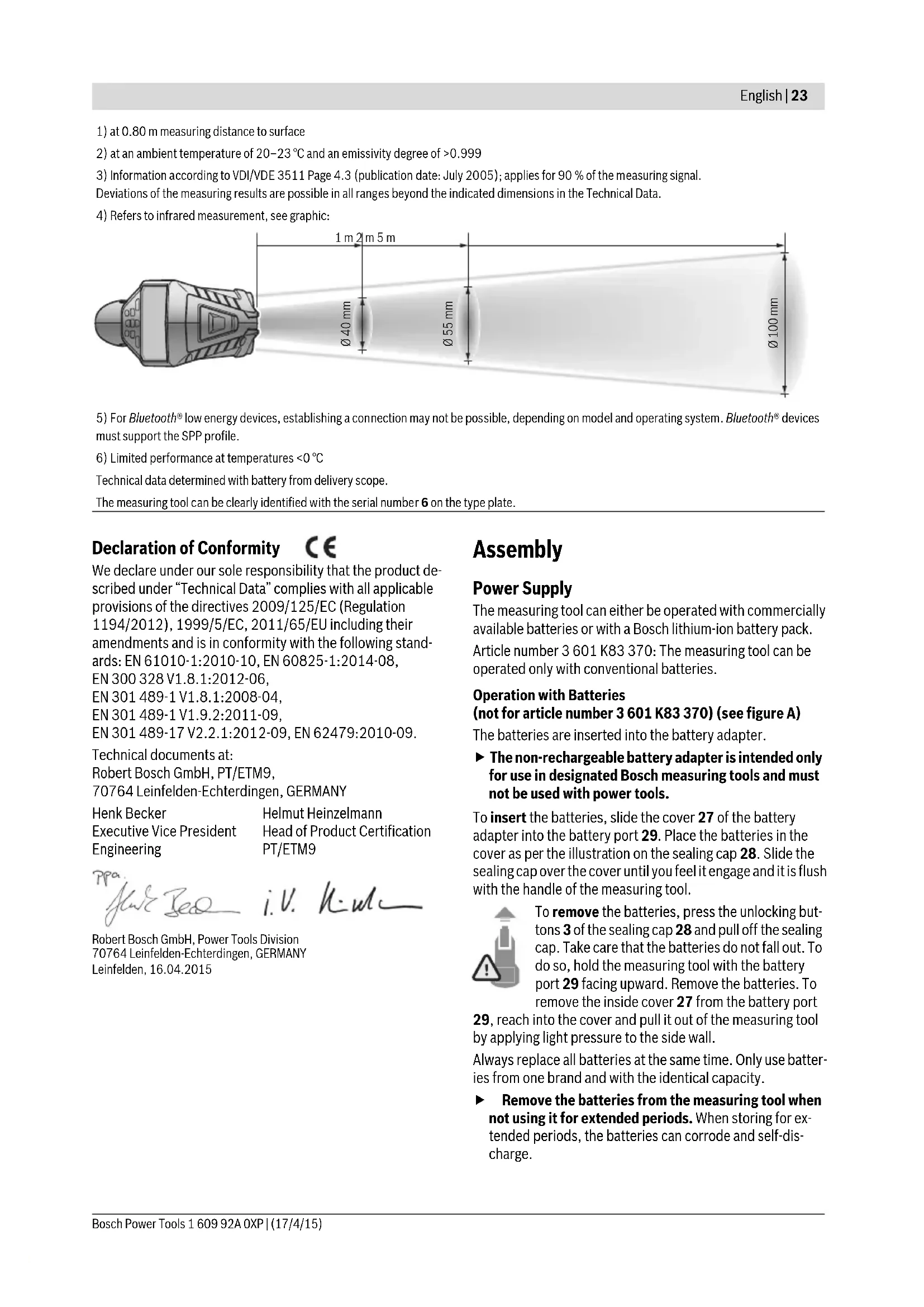
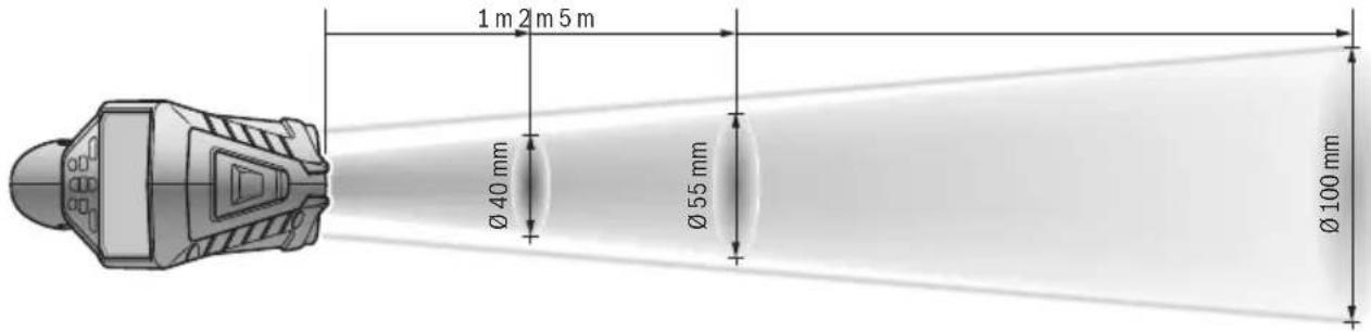
4) Refers to infrared measurement, see graphic:
5) For Bluetooth® low energy devices, establishing a connection may not be possible, depending on model and operating system. Bluetooth® devices must support the SPP profile.
6) Limited performance at temperatures < 0^
Technical data determined with battery from delivery scope.
The measuring tool can be clearly identified with the serial number 6 on the type plate.
Declaration of Conformity C
We declare under our sole responsibility that the product described under "Technical Data" complies with all applicable provisions of the directives 2009/125/EC (Regulation 1194/2012), 1999/5/EC, 2011/65/EU including their amendments and is in conformity with the following standards: EN 61010-1:2010-10, EN 60825-1:2014-08, EN 300 328 V1.8.1:2012-06, EN 301 489-1 V1.8.1:2008-04, EN 301 489-1 V1.9.2:2011-09, EN 301 489-17 V2.2.1:2012-09, EN 62479:2010-09.
Technical documents at: Robert Bosch GmbH, PT/ETM9, 70764 Leinfelden-Echterdingen, GERMANY
Henk Becker Helmut Heinzelmann
Executive Vice President Head of Product Certification
Engineering PT/ETM9

Robert Bosch GmbH, Power Tools Division 70764 Leinfelden-Echterdingen, GERMANY Leinfelden, 16.04.2015
Assembly
Power Supply
The measuring tool can either be operated with commercially available batteries or with a Bosch lithium-ion battery pack. Article number 3601 K83 370: The measuring tool can be operated only with conventional batteries.
Operation with Batteries
(not for article number 3601 K83 370) (see figure A)
The batteries are inserted into the battery adapter.
The non-rechargeable battery adapter is intended only for use in designated Bosch measuring tools and must not be used with power tools.
To insert the batteries, slide the cover 27 of the battery adapter into the battery port 29. Place the batteries in the cover as per the illustration on the sealing cap 28. Slide the sealing cap over the cover until you feel it engage and it is flush with the handle of the measuring tool.
Always replace all batteries at the same time. Only use batteries from one brand and with the identical capacity.
- Remove the batteries from the measuring tool when not using it for extended periods. When storing for extended periods, the batteries can corrode and self-discharge.
Operation with Battery Pack (not for article number 3601 K83 370) (see figure B)
Note: Use of battery packs not suitable for the measuring tool can lead to malfunctions of or cause damage to the measuring tool.
Note: The battery pack is supplied partially charged. To ensure full capacity of the battery pack, completely charge the battery pack in the battery charger before using for the first time.
Use only the chargers listed in the technical data. Only these battery chargers are matched to the lithium-ion battery of your measuring tool.
The lithium-ion battery pack can be charged at any time without reducing its service life. Interrupting the charging procedure does not damage the battery pack.
Following the automatic shut off of the measuring tool, do not continue to press the On/Off button. The battery can be damaged.
To insert the charged battery pack 30, slide it into the battery port 29 until you feel it engage and it is flush with the handle of the measuring tool.
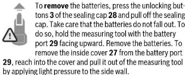
To remove the battery pack 30, press the unlocking buttons 3 and pull the battery pack out of the battery port 29. Do not exert any force.
Operation with Batteries (3 601 K83 370) (see figure C)
To open the battery lid 31, press the unlocking buttons 3 and remove the battery lid.
Make sure that you insert the batteries at the correct polarity according to the illustration on the battery lid.
Mount the battery lid 31 again until you feel it engage.
Always replace all batteries at the same time. Only use batteries from one brand and with the identical capacity.
- Remove the batteries from the measuring tool when not using it for extended periods. When storing for extended periods, the batteries can corrode and self-discharge.
Battery Status Indicator
The battery status indicator g on the display shows the charging state of the batteries or battery pack 30.
| Indication Capacity | |
| >2/3 | |
| ≤2/3 | |
| ≤1/3 | |
| ≤10 % | |
| Changing the Batteries or Battery Pack |
Operation
Initial Operation
- Keep the measuring tool dry and protect it from direct sunlight, dust and dirt.
- Do not subject the measuring tool to extreme temperatures or variations in temperature. As an example, do not leave it in vehicles for a long time. In case of large variations in temperature, allow the measuring tool to adjust to the ambient temperature before putting it into operation. In case of extreme temperatures or variations in temperature, the accuracy of the measuring tool can be impaired.
Ensure that the measuring tool is correctly acclimatised. In case of severe variations in temperature, the acclimatisation time may be up to 15 mins.
Avoid hard knocks to the measuring tool or dropping it. After severe external influences and in the event of abnormalities in the functionality, you should have the measuring tool checked by an authorised Bosch after-sales service agent.
The measuring tool is equipped with a radio interface. Local operating restrictions, e.g. in airplanes or hospitals, are to be observed.
Switching On and Off
Take the protective cap 21 off the infrared reception lens 23 and the protective cap 19 off the humidity and ambient temperature sensor 5. During work, ensure that the camera 22, reception lens 23 and sensor 5 are not closed off or covered, otherwise correct measurement will not be possible.
To switch on the measuring tool, press the On/Off button 12 or the measure button 4. A start sequence will appear on the display 18. After the start sequence, the measuring tool will be in the operating mode that was saved the last time the tool was switched off. The lasers are not yet switched on.
Only the first time the tool is started up, the "Tool" menu will additionally appear after the start sequence. In this menu you can define the settings of the measuring tool, such as the language of all indications (for operation, see "Tool" Submenu", page 30). Confirm the selected settings by pressing the left-hand function button 17. All settings can also be changed subsequently in the "Tool" submenu.
Do not leave the switched-on measuring tool unattended and switch the measuring tool off after use. Other persons could be blinded by the laser beam.
Do not point the laser beam at persons or animals and do not look into the laser beam yourself, not even from a large distance.
In the factory setting, the brightness of the display lighting is reduced 30 s after each button press to save energy. Pressing any button will switch the display lighting back to full strength. You can change this lighting time in the "Light Duration" menu (see "Light Duration", page 30).
To switch off the measuring tool, press the On/Off button.
The measuring tool saves the current operating mode and the settings and then switches off. Put the protective cap 21 back on the reception lens 23 and the protective cap 19 on the humidity and ambient temperature sensor 5.
Do not switch off the measuring tool by removing the battery pack or battery adapter because this may damage the internal memory in certain cases.
In the "Shutdown Time" menu you can set whether and after which time interval the measuring tool will automatically switch off if no button press/measurement occurs (see "Shutdown Time", page 30). The current operating mode and the settings are also saved when the tool switches off automatically.
If the battery or the measuring tool is not within the operating temperature range stated in the Technical Data, the measuring tool will shut down automatically after a brief warning (see "Troubleshooting - Causes and Corrective Measures", page 31). Allow the measuring tool to reach to the correct temperature and then switch it back on.
To save energy, only switch the measuring tool on when you are using it.
Setting the Zoom Level
For ongoing measurements and when rendering saved screenshots, the image detail on the display can be shown in three different zoom levels: 0.5m , 2m and 5m .
The zoom levels are optimised for the corresponding distance between measuring tool and measuring object: at a measuring distance of 2m , the zoom level "2 m" renders the (typically) best image detail.
The current zoom level appears in the indicator e. Press the upward arrow button 16 to increase the zoom level, and the downward arrow button 13 to reduce it.
Illuminating the Measuring Surface
When measuring in dark areas, you can switch on the light 24 to improve the display of the screen content. This can help you to achieve a better result when saving screenshots.
Press the button 14 to switch the light 24 on or off.
To save energy, the light switches off automatically when the brightness of the display lighting is reduced. You can change this lighting time in the "Light Duration" menu (see "Light Duration", page 30). The light is not automatically switched on when the display lighting is switched back on.
For energy-saving reasons, the light is not available when the charging state of the battery is in the critical range.
Preparing for Measurement
Setting the Emissivity Degree for Surface-temperature Measurements
To determine the surface temperature, the natural infrared heat radiation emitted by the object is measured contact-free. For correct measurements, the emissivity degree set on the measuring tool (see "Emissivity Degree", page 31) must be checked and if required, adapted to the object being measured prior to each measurement.
To change the set emissivity degree, open the "MainMenu" (see "Navigating the "Main Menu", page 30).
- A selection of saved emissivity degrees is available for some of the most common materials. Select the appropriate material in the "Material" menu item. The corresponding emissivity degree is shown in the line beneath.
- If you know the exact emissivity degree of your measuring object, you can also set it as a numerical value in the "Emissivity Degree" menu item.
Inform yourself of the emissivity degree of your material. In addition to the materials stored in the measuring tool, you will find more in the table below.
Material Emissivity degree
| Aluminium, polished 0.04 |
| Aluminium, oxidised 0.25 |
| Brass 0.04 |
| Brass, oxidised 0.61 |
| Iron, polished 0.20 |
| Iron, slightly rusted 0.65 |
| Iron, galvanised 0.25 |
| Chrome, polished 0.07 |
| Roofing felt 0.90 |
| Glass 0.88 |
Correct surface-temperature indications are only possible when the set emissivity degree and the emissivity degree of the object correspond. Correct notes on thermal bridges and the risk of mould thus also depend on the set emissivity degree.
If multiple objects made of a different material or having a different structure are measured during a measurement, the surface temperature indication is only binding for the objects matching the set emissivity degree.
Measuring Surface for Surface-temperature Measurements
The laser points generated by the measuring tool indicate the left-hand and right-hand boundaries of the circular measuring surface. The infrared radiation of this measuring surface is determined when performing contactless surface temperature measurement.
To achieve an optimum measuring result, align the measuring tool as perpendicular as possible to the centre of the measuring surface.
Do not point the laser beam at persons or animals and do not look into the laser beam yourself, not even from a large distance.
Increasing the distance between measuring tool and measuring object will increase the distance of the laser points and therefore the size of the measuring surface accordingly (see "Technical Data", page 22). The optimum measuring distance is 0.8m
Do not hold the measuring tool directly against hot surfaces. The measuring tool can be damaged through heat.
If the laser points are difficult to see, you can switch on the Measuring Frame b on the display (see "Measuring Frame", page 30). The measuring frame can be used as an indicator for the measuring surface and helps to improve orientation. Depending on the measuring distance, the measuring frame may deviate from the measuring surface. The area located between the laser points is decisive for the measurement.
Notes on the Measuring Conditions
Highly reflective or shiny surfaces (e.g. shiny tiles or polished metals) may impair the surface temperature measurement. If necessary, mask the measuring surface with a dark, matt adhesive tape that conducts heat well. Allow the tape to acclimatise briefly on the surface.
Ensure that a favourable measuring angle is used on reflective surfaces, in order to ensure that reflected heat radiation from other objects does not distort the result. For example, the reflection of your body heat may interfere with the measurement when measuring head-on from a perpendicular position. Measuring through transparent materials (e.g. glass or transparent plastics) is principally not possible.
The accuracy and reliability of the measuring results increase with better and more stable measuring conditions.
The humidity and ambient temperature sensor 5 can be damaged by chemical contaminants, such as through the evaporation of paints or enamels. Infrared temperature measurement is impaired by smoke, vapour or dusty air.
For this reason, ventilate indoor areas prior to measurement, especially when the air is contaminated or steamy.
After ventilating, allow the room to acclimate for a while until the usual temperature has been reached again.
Ambient temperature and relative humidity are measured directly on the measuring tool using the humidity and ambient temperature sensor 5. To achieve substantial results, do not hold the measuring tool directly over or next to sources of interference such as radiators or open liquids. Do not under any circumstances cover off the sensor 5.
Measuring Functions
Standard display screen

a Date/time: see "Time/Date", page 30
b Measuring frame: see "Measuring Surface for Surface-temperature Measurements", page 26
c Status indicator:

Measuring tool is ready to measure; press the measure button 4.

(Continuous) measurement running; lasers are switched on.

Measurement ended; lasers are switched off; measuring results are fixed.
d Audio signal switched off indicator (see "Audio Signal", page 30)
e Zoom level indicator: see "Setting the Zoom Level", page 25
f Bluetooth® switched on indicator (see "Data Transmission via Bluetooth®, page 29)
g Battery status indicator: see "Battery Status Indicator", page 24
h Function indicator/Measured value for relative humidity
i Function indicator/Measured value for ambient temperature
j Function indicator/Result for dew point temperature
k Minimum/maximum measured value for surface temperature during a measurement
I Result scale
mMenu symbol
n Surface temperature alarm indicator: see "Surface Temperature Alarm", page 27
o Measured value for surface temperature measurement
p Current mode
q Mark for measured value or result (depending on selected mode)
r Gallery symbol
s Function indicator/Measured value for average temperature
t Function indicator/Measured value for contact temperature
u Emissivity degree indicator
v Memory symbol
Single Measurement
Briefly press the measure button 4 once to switch on the lasers and trigger an individual measurement in the selected mode. Hold the measuring tool aimed at the measuring object without moving it until the measured value is displayed. Measurement can take up to 1 second.
The lasers switch off automatically after completion of the measurement. The measuring results appear on the display.
Press the measure button 4 again to start a new measurement with the set measuring parameters.
Continuous Measurement (Tracking)
Press and hold the measure button 4 to perform continuous measurements in the selected mode. The lasers remain switched on. Using slow movements, aim the laser points one after the other at all surfaces whose temperature you want to measure. Move the measuring tool slowly in the room to perform humidity and ambient temperature measurements.
The indications on the display are continually updated. As soon as you let go of the measure button 4, the measurement is interrupted and the lasers are switched off. The last measuring results are fixed on the display.
Press the measure button 4 again to start a new measurement with the set measuring parameters.
Saving/Displaying/Sending Measuring Results
After completion of a measurement, the memory symbol v appears on the display to indicate that you can save the measuring results. To do so, press the save/send button 9.
The measuring results are saved as a JPG file (screenshot of the fixed display).

- To display saved screenshots, press the left-hand function button 17 under the gallery symbol r. The most recently saved photo appears on the display.
- Press the right-hand 11 or left-hand 15 arrow button to switch between the saved screen-shots.
- To send the displayed measuring result via Bluetooth®, press the save/send button 9. If the Bluetooth® connection is not yet switched on (see “Data Transmission via Bluetooth®”, page 29), it is activated by pressing the save/send button.

- To delete the displayed screenshot, press the right-hand function button 10 under the trash can symbol.

- To confirm the deletion, press the left-hand function button 17 under the tick symbol.

- To cancel the deletion, press the right-hand function button 10 under the cross symbol.

- To exit the gallery view and return to the measuring mode, press the left-hand function button 17 under the back symbol.
You can also delete all saved files at once. For this, see "Delete All Images", page 30.
Surface-temperature-mode
In surface-temperature-mode, the surface temperature of an object is measured.
In this mode you can, for example, search for overheated fuses or locate heating pipes or hot water pipes.
To switch to surface temperature mode, return to the standard display screen if not already on it. Then press the left-hand arrow button 15 or the right-hand arrow button 11 repeatedly until the "Surface Temperature" window is displayed with a brief explanation of the mode. To hide the explanation prematurely, press the save button 9. To hide the explanation and immediately start a measurement, press the measure button 4.
Press the measure button 4 and aim the measuring tool perpendicular to the centre of the measuring object. After completion of the measurement, the surface temperature of the measuring object most recently aimed at is fixed in the indicator o.
When performing continuous measurements, the most recently measured surface temperature is displayed with the mark q on the result scale I. The minimum and maximum temperature values of the measurement appear in the indicator k as soon as the difference between the measured values is more than 3^ . This enables you to tell how high the current measured value is in relation to the temperatures already measured.
Surface Temperature Alarm
The surface temperature alarm can be used in all modes. You can set a minimum and a maximum temperature.
If the temperature is below the Minimum Temperature, the temperature alarm indicator n flashes blue and a warning signal sounds if the audio signal is switched on.
If the temperature exceeds the Maximum Temperature, the temperature alarm indicator n flashes red and a warning signal sounds if the audio signal is switched on.
To use the surface temperature alarm, open the "MainMenu" (see "Navigating the "Main Menu", page 30).
- Select the "Functions" submenu.
- Set "Alarm min/max" to "On".
- Set the minimum temperature under "Alarm min".
- Set the maximum temperature under "Alarm max".
The minimum and maximum temperatures are also saved when you set the alarm to "Off".
Contact Temperature Measurement
Contact temperature measurement enables the temperature of an object to be measured directly using a conventional type K thermocouple.
Note: Only use type K thermocouples. Incorrect measuring results may be obtained if other types of thermocouples are connected.
Fold open the cover 1 and connect the thermocouple to the connection 25.
Read and observe the operating instructions of the thermocouple.
As soon as a thermocouple is connected, the indicator t appears on the display. The measured value of the indicator is continually updated. To achieve a reliable result, wait until the measured value no longer changes. This can take several minutes depending on the version of thermocouple.
The contact temperature can be measured in every mode in addition to the surface temperature. However, the surface temperature is always used to determine thermal bridges and mould risk.
If the thermocouple is removed, the function indicator t extinguishes on the display. Close the cover 1 again after removing the thermocouple.
Thermal-bridge-mode
In thermal-bridge-mode, surface and ambient temperature are measured and compared with each other. In case of larger differences between both temperatures, a thermal-bridge warning is indicated (see "Thermal Bridge", page 31).
To switch to thermal bridge mode, return to the standard display screen if not already on it. Then press the left-hand arrow button 15 or the right-hand arrow button 11 repeatedly until the "Thermal Bridge" window is displayed with a brief explanation of the mode. To hide the explanation prematurely, press the save button 9. To hide the explanation and immediately start a measurement, press the measure button 4.
Press the measure button 4 and aim the measuring tool perpendicular to the centre of the measuring object. After completion of the measurement, the surface temperature of the measuring object most recently aimed at is fixed in the indicator o and the ambient temperature in the indicator i.
The measuring tool automatically compares the values and shows the interpretation of the values with the mark q on the result scale I:
- Mark q in green range (temperature difference < 3.5^ ): Slight temperature difference; no thermal bridges present
- Mark q in yellow range (temperature difference 3.5^ to 6.5^ ): Temperature difference is borderline; there may possibly be a thermal bridge in the measuring area. The insulation may be inadequate at this position. Repeat the measurement if necessary at a later point in time. When doing so, pay attention to external conditions which can affect the measurement, e.g. whether the measuring surface is heated up by direct sunlight or the measuring surface is next to an open door and the fresh air temporarily lowers the temperature.
- Mark q in red range (temperature difference >6.5^ ): The surface temperature within the measuring surface deviates significantly from the ambient temperature. There is a thermal bridge in the measuring area, which is an indication of poor insulation.
You can manually adjust the temperature difference from which the mark is displayed in the red range. To do so, open the "Main Menu" (see "Navigating the Main Menu", page 30). Select the "Functions" submenu. Set the desired temperature difference under "Thermal Bridge".
If there are thermal bridges, check the thermal insulation in this area.
Dew Point Mode
The ambient temperature and relative humidity (see "Relative Humidity", page 31) are measured in dew point mode. The dew point temperature is calculated based on both values (see "Dew Point Temperature", page 31). The surface temperature is also measured.
The dew point temperature is compared with the surface temperature and the result is interpreted as to the risk of mould.
Please note that the measuring results are always valid only for the current measuring conditions. A measurement over time is not possible. If critical measuring results are obtained, you should repeat the measurement at different times and under different conditions.
To switch to dew point mode, return to the standard display screen if not already on it. Then press the left-hand arrow button 15 or the right-hand arrow button 11 repeatedly until the "Dew Point" window is displayed with a brief explanation of the mode. To hide the explanation prematurely, press the save button 9. To hide the explanation and immediately start a measurement, press the measure button 4.
Press the measure button 4 and aim the measuring tool perpendicular to the centre of the measuring object. After completion of the measurement, the surface temperature of the measuring object most recently aimed at is fixed in the indicator o, the ambient temperature in the indicator i and the relative humidity in the indicator h. The calculated dew point temperature is displayed in j.
The measuring tool automatically compares the values and shows the interpretation of the values with the mark q on the result scale I:
- Mark q in green range: There is no mould risk under the current conditions.
- Mark q in yellow range: The values are borderline; pay attention to room temperature, thermal bridges and humidity, and repeat the measurement if necessary at a later point in time.
- Mark q in red range: There is an increased mould risk because the humidity is too high or the surface temperature is close to the dew point temperature. The conspicuous value flashes in the indicator.
A mould risk warning is given when the surface temperature is 80% of the dew point temperature. When the risk of mould is given, you should - depending on the cause - reduce the humidity through more frequent and thorough ventilation, increase the room temperature and eliminate thermal bridges.
Note: The measuring tool cannot detect mould spores. It only indicates the possible formation of mould when the conditions remain the same.
User Mode
Surface temperature, ambient temperature and relative humidity are measured in user mode. The dew point temperature and the average temperature (mean value of the surface temperatures during a continuous measurement) are calculated based on these values.
You can hide the following values in the display as required: average temperature, relative humidity, ambient temperature and dew point temperature.
To do so, open the "Main Menu" (see "Navigating the "Main Menu", page 30). Select the "Functions" submenu and then "User Mode". There you can switch the indicators "Average Temp. ", "Humidity", "Room Temperature" and "Dew Point" on and off.
For surface temperature measurements you can choose whether the minimum and maximum values k of the result scale I are adapted automatically or defined manually. To do so, go to the "User Mode" menu and then to the "Scale Range" submenu.
- Select "Auto" if you want the values k to be determined automatically as in surface temperature mode. The minimum and maximum temperature values of the measurement appear in the indicator k as soon as the difference between the measured values is more than 3^ .
- Select "Preset" to define the values manually. Set the desired values in the "User Mode" menu under "Scale Lower Limit" and "Scale Upper Limit". The manually set minimum and maximum values appear in the indicator k. This enables you to, for example, make screenshots of different measurements comparable using the mark q.
To switch to user mode, return to the standard display screen if not already on it. Then press the left-hand arrow button 15 or the right-hand arrow button 11 repeatedly until the "User Mode" window is displayed with a brief explanation of the mode. To hide the explanation prematurely, press the save button 9. To hide the explanation and immediately start a measurement, press the measure button 4.
Press the measure button 4 and aim the measuring tool perpendicular to the centre of the measuring object. The selected values are displayed after completion of the measurement.
Data Transmission
Data Transmission via USB Interface
Fold open the cover 1. Connect the micro USB socket 26 of the measuring tool to your computer or notebook using the micro USB cable provided 8. The saved JPG files can be copied, moved or deleted from the internal memory of the measuring tool. Close the cover 1 again when you remove the micro USB cable.
Note: Connect the measuring tool via USB only to a computer or notebook. The tool may be damaged if connected to other devices.
Note: The battery pack of the measuring tool cannot be charged via the USB interface. To charge the battery pack, see "Operation with Battery Pack", page 24.
Data Transmission via Bluetooth®
The measuring tool is equipped with a Bluetooth® module, which enables data transmission via radio technology to certain mobile terminals/devices with a Bluetooth® interface (e.g., smartphones, tablets).
Information about system requirements for a Bluetooth connection can be found on the Bosch website at
www.bosch-professional.com.
To switch on the Bluetooth® connection on the measuring tool, open the "MainMenu" (see "Navigating the Main Menu", page 30) and set "Bluetooth" to "On". The indicator f will appear on the display. Ensure that the Bluetooth® interface is activated on your mobile terminal/device.
Special Bosch applications (apps) are available to extend the functional range of the mobile terminal/device and for simplification of the data processing. Depending on terminal/device, these can be downloaded at the respective app stores:


The connection between mobile terminal/device and measuring tool is established after the Bosch application has started (if Bluetooth® modules are activated). If multiple active measuring tools are found, select the appropriate measuring tool. A connection will be established automatically if only one active measuring tool is found.
Note: When establishing the connection between the measuring tool and the mobile terminal/device (e.g., smartphone, tablet) the first time (pairing), the measuring tool's PIN code may be requested. In this case, enter "0000".
When transmitting data by means of Bluetooth®, time lags may occur between mobile terminal/device and measuring tool as a result of poor reception conditions.
"Main Menu"
Navigating the "Main Menu"

- Togo to the "Main Menu", press the right-hand function button 10 under the menu symbol m on the standard display screen.
- To navigate within a menu level, press the upward arrow button 16 or the downward arrow button 13 repeatedly until the desired menu item is highlighted in colour.
- If there is a submenu for a highlighted menu item, this will be indicated by an arrow pointing to the right next to "set ..." Press the right-hand arrow button 11 to enter the submenu.
- If there are multiple options for a highlighted menu item, the current setting is displayed between two arrows. To change the setting, press the left-hand arrow button 15 or the right-hand arrow button 11. Numerical values are changed faster if you keep the corresponding arrow button pressed.
- In some menu items you can switch a function on or off. To switch off, press the left-hand arrow button 15 so that "Off" is highlighted. To switch on, press the right-hand arrow button 11 so that "On" is highlighted. You can also switch the function on and off in the menu by pressing the save/send button 9.
- To switch to a parent menu, press the left-hand function button 17 under the back symbol. The selected settings will be saved.
- To exit the "MainMenu" and return direct the standard display screen, press the right-hand function button 10 under the house symbol. The selected settings will be saved.
- You can also press the measure button 4 to exit any menu and return to the standard display screen. If the button is pressed once, the selected settings will be saved but no measurement will be initiated.
"Tool" Submenu
Open the "MainMenu" and select the "Tool" submenu. It contains the following menu items:
Language:
In the "Language" menu you can change the language of all indications.
- Time/Date:
To change the date and time in the indicator a, open the "Time & Date" submenu. In this submenu you can also change the date and time format.
To exit the "Time & Date" submenu, press either the left-hand function button 17 under the tick symbol to save the settings or the right-hand function button 10 under the cross symbol to discard the changes.
Unit:
In the "Unit" menu you can choose whether the temperature specifications are displayed in "°C" or "°F".
Audio Signal:
In the "Audio Signals" menu you can switch the audio signal that sounds upon a surface temperature alarm on and off.
- Measuring Frame:
In the "Measuring Frame" menu you can switch the measuring frame b on the display on and off.
Colour Scheme:
In the "Colour Scheme" menu you can choose the colour of the temperature values and other indications on the display. The setting will also be applied to saved screenshots.
- Shutdown Time:
In the "Shutdown Time" menu you can choose the time interval after which the measuring tool will automatically shut down if no button is pressed. You can also deactivate the automatic shutdown by selecting the "Never" setting. The shorter the shutdown time, the more energy you can save.
Light Duration:
In the "Light Duration" menu you can choose the time interval after which the brightness of the display lighting will reduce if no button is pressed on the measuring tool. You can also illuminate the display permanently by selecting the "Always" setting. The shorter the light duration, the more energy you can save.
-Delete All Images:
In the "Delete All Images" menu you can delete all files in the internal memory at once. Press the right-hand arrow button 11 for "more ..." to enter the submenu. Then press either the left-hand function button 17 under the tick symbol to delete all files, or the right-hand function button 10 under the cross symbol to cancel the operation.
- Tool Information:
Open the "Tool Information" submenu for information about the measuring tool. There you will find the serial number of the measuring tool and the installed software version.
Troubleshooting - Causes and Corrective Measures
| Error Cause Corrective Measure | ||
| Measuring tool cannot be switched on. | Battery pack or batteries empty | Charge the battery pack or change the batteries. |
| Battery too warm or too cold | Allow the battery to reach the correct temperature or change it. | |
| Measuring tool too warm or too cold | Allow the measuring tool to reach the correct temper- ature. | |
| H A | Image memory defective Format the internal memory by deleting all images (see “Delete All Images”, page 30). If the problem persists, send the measuring tool to an authorised Bosch after-sales service agent. | |
| Image memory full If required, transfer the images to another storage medium (e.g. computer or notebook). Then delete the images in the internal memory. | ||
| F F A | Measuring tool is defective Send the measuring tool to an authorised Bosch after-sales service agent. | |
| Function indicator t for contact tempera-ture measurement does not appear on the display. | Connection 25 for thermo-couple defective | Send the measuring tool to an authorised Bosch after-sales service agent. |
| Measuring tool cannot be connected to a computer. | Measuring tool not recog-nised by computer. | Check whether the driver on your computer is up to date. It may be necessary to have a newer operating system version on your computer. |
| Micro USB connection or micro USB cable defective | Check whether the measuring tool can be connected to a different computer. If not, send the measuring tool to an authorised Bosch after-sales service agent. | |
| Humidity and ambient tem- perature sensor 5 defective | The other functions of the measuring tool can still be used. Send the measuring tool to an authorised Bosch after-sales service agent. | |
Definitions
Infrared heat radiation
Infrared heat radiation is electromagnetic radiation emitted by every body. The amount of radiation depends on the temperature and the emissivity degree of the body.
Emissivity Degree
The emissivity degree of an object depends on the material and the structure of its surface. It states how much infrared heat radiation the object emits compared to an ideal heat emitter (black body, emissivity degree = 1 ).
Thermal Bridge
A thermal bridge is an object that undesirably transmits heat outwards or inwards, therefore differing significantly from the temperature of the rest of a wall or from the desired temperature of a wall.
As the surface temperature at thermal bridges is lower than in the rest of the room, the risk of mould increases significantly at these locations.
Relative Humidity
The relative humidity provides information on how intensive the air is saturated with water vapour. It is stated as a percentage of the maximum amount of water vapour that the air can absorb. The maximum amount of water vapour depends on the temperature: The higher the temperature, the more amount of water vapour the air can absorb.
When the relative humidity is too high, the risk of mould increases. Too low humidity can lead to health impairments.
Dew Point Temperature
The dew point temperature indicates the temperature at which the water vapour in the air starts to condense. The dew point temperature depends on the relative humidity and the air temperature.
When the temperature of a surface is below the dew point temperature, water begins to condense on this surface. The larger the difference of both temperatures and the higher the relative humidity, the greater the condensation.
Condensate on surfaces is a major cause for the formation of mould.
Maintenance and Service
Maintenance and Cleaning
Store and transport the measuring tool only in a suitable container such as the original packaging or the protective pouch (accessory). Do not, as an example, store the measuring tool in a plastic bag, as the evaporation could damage the humidity and temperature sensor 5. Do not affix any stickers near to the sensor on the measuring tool.
Do not store the measuring tool for long periods out of a humidity range between 30 to 50% . When the measuring tool is stored too moist or too dry, faulty measurements can occur when starting operation.
Keep the measuring tool clean at all times.
Wipe off debris using a moist and soft cloth. Do not use any cleaning agents or solvents.
When cleaning, fluids should not penetrate into the measuring tool.
Be very careful especially when cleaning humidity and ambient temperature sensor 5, the camera 22, the reception lens 23, the light 24 and the laser beam exit openings 2:
Ensure that there is no tint on the camera, the reception lens or the laser beam exit openings. Clean the camera, the reception lens and the laser beam exit openings only with cleaning agents also suitable for camera lenses. Do not attempt to remove dirt from the sensor, camera or reception lens using pointed objects, and do not wipe over the camera and reception lens (risk of scratching).
If the event of a repair, send in the measuring tool in the original packaging or in the protective pouch (accessory).
After-sales Service and Application Service
Our after-sales service responds to your questions concerning maintenance and repair of your product as well as spare parts. Exploded views and information on spare parts can also be found under:
www.bosch-pt.com
Bosch's application service team will gladly answer questions concerning our products and their accessories.
In all correspondence and spare parts orders, please always include the 10-digit article number given on the type plate of the measuring tool.
Great Britain
Robert Bosch Ltd. (B.S.C.)
P.O.Box 98
Broadwater Park
North Orbital Road
Denham
Uxbridge
UB95HJ
At www.bosch-pt.co.uk you can order spare parts or arrange the collection of a product in need of servicing or repair.
Tel. Service: (0344) 7360109
E-Mail: boschservicecentre@bosch.com
Ireland
Origo Ltd.
Unit 23 Magna Drive
Magna Business Park
City West
Dublin 24
Tel. Service: (01) 4666700
Fax: (01) 4666888
Australia, New Zealand and Pacific Islands
Robert Bosch Australia Pty. Ltd.
Power Tools
Locked Bag 66
Clayton South VIC 3169
Customer Contact Center
Inside Australia:
Phone: (01300) 307044
Fax: (01300) 307045
Inside New Zealand:
Phone: (0800) 543353
Fax: (0800) 428570
Outside AU and NZ:
Phone: +61 3 95415555
www.bosch.com.au
Supplier code ERAC000385
Republic of South Africa
Customer service
Hotline: (011) 6519600
Gauteng - BSC Service Centre
35 Roper Street, New Centre
Johannesburg
Tel.: (011) 4939375
Fax: (011) 4930126
E-Mail: bsctools@icon.co.za
KZN - BSC Service Centre
Unit E, Almar Centre
143 Crompton Street
Pinetown
Tel.: (031) 7012120
Fax: (031) 7012446
E-Mail: bsc.dur@za.bosch.com
Western Cape - BSC Service Centre
Democracy Way, Prosperity Park
Milnerton
Tel.: (021) 5512577
Fax: (021) 5513223
E-Mail: bsc@zsd.co.za
Bosch Headquarters
Midrand, Gauteng
Tel.: (011) 6519600
Fax: (011) 6519880
E-Mail: rbsa-hq.pts@za.bosch.com
Transport
The usable lithium-ion battery packs are subject to the Dangerous Goods Legislation requirements. The user can transport the battery packs by road without further requirements. When being transported by third parties (e.g. via air transport or forwarding agency), special requirements on packaging and labelling must be observed. For preparation of the item being shipped, consulting an expert for hazardous material is required.
Dispatch battery packs only when the housing is undamaged. Tape or mask off open contacts and pack up the battery pack in such a manner that it cannot move around in the packaging. Please also observe possibly more detailed national regulations.
Disposal

Measuring tools, battery packs/batteries, accessories and packaging should be sorted for environmental-friendly recycling.
Do not dispose of measuring tools and batteries/rechargeable batteries into household waste!
Only for EC countries:
According to the European Guideline 2012/19/EU, measuring tools that are no longer usable, and according to the European Guideline 2006/66/EC, defective or used battery packs/batteries, must be collected separately and disposed of in an environmentally correct manner.
Batteries no longer suitable for use can be directly returned at:
Great Britain
Robert Bosch Ltd. (B.S.C.)
P.O.Box 98
Broadwater Park
North Orbital Road
Denham
Uxbridge
UB95HJ
At www.bosch-pt.co.uk you can order spare parts or arrange the collection of a product in need of servicing or repair.
Tel. Service: (0344) 7360109
E-Mail: boschservicecentre@bosch.com
Battery packs/batteries:
Li-ion:
Please observe the instructions in section "Transport", page 33.
Integrated batteries may only be removed for disposal by qualified personnel. Opening the housing shell can destroy the measuring tool.
To remove the lithium-ion backup battery from the measuring tool, first remove the battery pack 30 or the battery adapter. Remove the protective glass of the display and then the keypad.
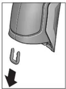
As shown in the illustration, remove the U-shaped clips holding the housing shells together.
Unscrew the screws on the housing and take off the housing shell with the type plate.
The backup battery (button cell) is located on the circuit board inside the housing. Slide it out of its holder and dispose of it in an environmentally correct manner.
Subject to change without notice.
Français
Henk Becker Helmut Heinzelmann Executive Vice President Head of Product Certification Engineering PT/ETM9

Robert Bosch GmbH, Power Tools Division 70764 Leinfelden-Echterdingen, GERMANY Leinfelden, 16.04.2015
Montage
Humidity relative to the air
Robert Bosch (France) S.A.S.
Leer y observar todas las instrucciones, para trabajo sin peligro y riesgo con el aparato de medicación. Si el aparato de medicación no se utilizes相关政策,SEO,SEO,SEO,SEO,SEO,SEO,SEO,SEO,SEO,SEO,SEO,SEO,SEO,SEO,SEO,SEO,SEO,SEO,SEO,SEO,SEO,SEO,SEO,SEO,SEO,SEO,SEO,SEO,SEO,SEO,SEO,SEO,SEO,SEO,SEO,SEO,SEO,SEO,SEO,SEO,SEO,SEO,SEO,SEO,SEO,SEO,SEO,SEO,SEO,SEO, SEO, SEO, SEO, SEO, SEO, SEO, SEO, SEO, SEO, SEO, SEO, SEO, SEO, SEO, SEO, SEO, SEO, SEO, SEO, SEO, SEO, SEO, SEO, SEO, SEO, SEO, SEO, SEO, SEO, SEO, SEO, SEO, SEO, SEO, SEO, SEO, SEO, SEO, SEO, SEO, SEO, SEO, SEO, SEO, SEO, SEO
Henk Becker Helmut Heinzelmann Executive Vice President Head of Product Certification Engineering PT/ETM9

Robert Bosch GmbH, Power Tools Division 70764 Leinfelden-Echterdingen, GERMANY Leinfelden, 16.04.2015
Montaje
Alimentación
Henk Becker Helmut Heinzelmann Executive Vice President Head of Product Certification Engineering PT/ETM9

Robert Bosch GmbH, Power Tools Division 70764 Leinfelden-Echterdingen, GERMANY Leinfelden, 16.04.2015
Montagem
Henk Becker Helmut Heinzelmann
Executive Vice President Head of Product Certification
Engineering PT/ETM9

Robert Bosch GmbH, Power Tools Division 70764 Leinfelden-Echterdingen, GERMANY Leinfelden, 16.04.2015
Montaggio
Henk Becker Helmut Heinzelmann
Executive Vice President Head of Product Certification
Engineering PT/ETM9

Robert Bosch GmbH, Power Tools Division 70764 Leinfelden-Echterdingen, GERMANY Leinfelden, 16.04.2015
Montage
Energievoorziening
Henk Becker Helmut Heinzelmann
Executive Vice President Head of Product Certification
Engineering PT/ETM9

Robert Bosch GmbH, Power Tools Division 70764 Leinfelden-Echterdingen, GERMANY Leinfelden, 16.04.2015
Montering
Energiforsyning
Navigation i, hovedmenuen

Bosch Service Center
Telegrafvej 3
2750 Ballerup
Pá www.bosch-pt.dk kander online bestiles reservedeleller oprettes en reparations ordre.
Tlf. Service Center: 44898855
Fax: 44898755
E-Mail: vaerktoej@dk.bosch.com
Transport
31 Batterifacets lock
29 Batterischakt
Henk Becker Helmut Heinzelmann Executive Vice President Head of Product Certification Engineering PT/ETM9

Robert Bosch GmbH, Power Tools Division 70764 Leinfelden-Echterdingen, GERMANY Leinfelden, 16.04.2015
Montage
Energiforsörjning
Bosch Service Center
Telegrafvej 3
2750 Ballerup
Danmark
Tel.: (08) 7501820 (inom Sverige)
Fax: (011) 187691
Transport
9 Knapp lagre/sende via Bluetooth®
14 Av/pa-knapp for lys
15 Venstrepil
16 Pil opp/əke zoom-niva
25 Type K-tilkobling for termoelement
26 Mikro-USB-kontakt
27 Hylster for batteriadapter
28 Deksel for batteriadapter
29 Batterisjakt
30 Batteri*
Henk Becker Helmut Heinzelmann Executive Vice President Head of Product Certification Engineering PT/ETM9

Robert Bosch GmbH, Power Tools Division 70764 Leinfelden-Echterdingen, GERMANY Leinfelden, 16.04.2015
Montering
Energitilforsel
Henk Becker Helmut Heinzelmann Executive Vice President Head of Product Certification Engineering PT/ETM9

Robert Bosch GmbH, Power Tools Division 70764 Leinfelden-Echterdingen, GERMANY Leinfelden, 16.04.2015
Asennus
Energiahuolto
Henk Becker Helmut Heinzelmann
Executive Vice President Head of Product Certification
Engineering PT/ETM9

Robert Bosch GmbH, Power Tools Division 70764 Leinfelden-Echterdingen, GERMANY Leinfelden, 16.04.2015
Συναρμολόγηση
Tpofoδoia
HTpOPOBOTnTou epyaleiou mETPnonc dEayetal n e unatapie c ano to koiio eunopio n pe enavaqoptu oevn unatapia tovw laiou ano tv Bosch.
Xpovoc anevpeyoinoic:
27 Batarya adaptoru kilifi
28 Batarya adaptoru kapagi
29 Akü yuvası
30 Akü*
31 Batarya gozukapagi
Henk Becker Helmut Heinzelmann
Executive Vice President Head of Product Certification
Engineering PT/ETM9

Robert Bosch GmbH, Power Tools Division 70764 Leinfelden-Echterdingen, GERMANY Leinfelden, 16.04.2015
Montaj
Enerji saglama
Bosch San. ve Tic. A.S.
Ahi Evran Cad. No:1 Kat:22
Polaris Plaza
80670 Maslak/istanbul
Bosch Uzman Ekibi +90 (0212) 367 18 88
Işiklar LTD.ŞTI.
Kizilay Cad. No: 16/C Seyhan
Adana
Tel.: 0322 3599710
Tel.: 0322 3591379
Henk Becker Helmut Heinzelmann Executive Vice President Head of Product Certification Engineering PT/ETM9

Robert Bosch GmbH, Power Tools Division 70764 Leinfelden-Echterdingen, GERMANY Leinfelden, 16.04.2015
Montaz
Zasilanie
Robert Bosch Sp. z o.o.
Henk Becker Helmut Heinzelmann
Executive Vice President Head of Product Certification
Engineering PT/ETM9

Robert Bosch GmbH, Power Tools Division 70764 Leinfelden-Echterdingen, GERMANY Leinfelden, 16.04.2015
Montáž
Napájení energii
Mérici préstroj lze provozovats běznymi bateriemi nebo s akumulatórem Li-ion firmy Bosch.
Cislo zboz 3601 K83 370: Merici pristroj Ize pouzivat vhyadrnse bznne prodavanymi bateriemi.
Provoz s bateriemi (nikoli u objednaciho cisla 3601 K83 370) (viz obr. A)
Bosch Service Center PT
K Vapence 1621/16
692 01 Mikulov
Na www.bosch-pt.cz si si muzete objednat opravu Vaseho stroje nebo nahradni dily online.
Tel.: 519305700
Fax: 519305705
E-Mail: servis.naradi@cz.bosch.com
www.bosch.cz
Preprava
Henk Becker Helmut Heinzelmann
Executive Vice President Head of Product Certification
Engineering PT/ETM9

Robert Bosch GmbH, Power Tools Division 70764 Leinfelden-Echterdingen, GERMANY Leinfelden, 16.04.2015
Montáž
Napájanie
Henk Becker Helmut Heinzelmann
Executive Vice President Head of Product Certification
Engineering PT/ETM9

Robert Bosch GmbH, Power Tools Division 70764 Leinfelden-Echterdingen, GERMANY Leinfelden, 16.04.2015
Összeszerelés
Energiaellatas
Available on the App Store

PekomeHnyeTc OuynCTNtB HnCtpymEnT OT nbIIN Nocne KaKdo- ro HCNoJIb30BaHn.
Xpahenne
- Heo6xOdImO XpaHntb B CyXOM MeCTe
Heo6xOdHMO XpaHnTb BdaHOT NCTOCHNKOB IOBbIeHHbIX TeMnepaTpN BO3deNCTBnA COINHehBix Nyuei - npH xpaHenn HEO6xoDnMo n36eRaTb pe3KOro nepenada TeMnepeatyp
ecnHnHTpyMeHIOCTaBJIeTcB MRAKoCymKe HINPiactNKOBOM KeIce peKOMeHdyeTcXpaHNTb HHCTpyMeHT B3Toi 3aUHTHOyNAKOBe - noDpo6HbIe Tpe6oBaHnK yCNoBnM XpaHeHn CMOtpnTe B FOCT 15150 (YcNoBne 1)
TpaHcnpOpBbKa
Kateropnueckn He donyckaetcnaeHne nIIObIe MexaHnueckne Bo3deNCTBnHa ynaKOBky npn TpaHCnpTnpOBke
- npn pa3rpy3ke/nprgy3ke He donyckaetc HcnoIb3OBaHne IIO6oBvndaTeXhNKn,pa6OtaIoSeI IO npHHuNy 3axHmay ynaKOBKn
IIOJPO6HbIe Tpe6oBaHnK YcNObHm TpaHcNOpTnpOBKn CMOTpHTe B FOCT 15150 (YcNoBHe 5)
Yka3aHnno 6e30nacHOCTN

IJa o6ecneuHn 6e3oNaCHO nHaedXHO pa60TbIC H3MepHTenbHbIM HcTpymEMTO D0JXHbI 6bITb npOHTaHb I CO6IOdaTbc8 BCE HcTpyKcHn. Ncnonb3OBaHne H3MpTeBHorO HHCTpymEHTa He B COOTBeTCTBnC
HACTOaMHN yKa3aHnMn 4peBaTO NOBpeXeHn HHTERpHPOBaHHbIX 3aunTHbIX MEXaHN3MOB. HNKoRda He n3MeHnTe Do Hey3HaBaemocTH npedynpeHntbHbIe Ta6nKn Ha n3MePHTenbHom HHCTpyMeHTe. XOPOUo COXPAHnTE 3Ty IHCTPYKcNIO INPEPEDABAHTE EE BMECTC INPEDAUYEN3MEPHTenbHOrO IHCTPYMEHTA.
BHHMaHHe - HcNoIb3OBAHHe dpyrHex He yonmHytbIX 3decb 3nemEntOB ynpabIeHn H perynHpOBaHn Hnn dpyrHex MeTOIOB 3KcNlyaTaun MoKeT NOBeprHytb Bac onacHomy DnA 3dOpOBb n3nyeHnIO.
H3MepHTenbHbI HNCTpymeNT noCTabnEeTc c npedynpaHTenbHO Ta6nuko (Ha cTpaHnue c n3o6paKeHHem H3MepHTenbHO To HHCTpymeHTa NOKa3aHa IOp HoMePOM 7).

IEC 60825-1:2014
<1mW,635nm
He hnpablaIte lyu na3epa Ha IIOdeHnXnBOTbIX HcMn He CMOTpnte Ha npamO nnOpaxKaembl nyu na3epa.
3TOT Nyu MoXeT CInMbI JIOJe, CTaTb IINHnHO HeCuAcTHOrO CnyaI INN NOBpeINb Tna3a.
B cnye nonaahanna na3epnor noya b rna3 rna3a HxKHO HamepeHHO 3aKpbItb N HemeJeHNO OTBepHyTbC8OTnya.
He meHnTe HnUero B nAzeepHom ycTpoNCTBe.
He npmeHne Ia3epHbIe OUKB KauceCTBe 3aHTbIX OOKOB. Ia3epHbIe OUK CnyKAT DnI LyuWero pacno3HaBaHn Ia3epHO LyuA, ONaKO OHn He 3aUHuaOT OT Ia3epHO H3nyeHn.
He npmehnTe na3ephble ouKn B kaueCTbe conheHybIX OOKOB HnB ynnHOM dBHXeHH. Na3ephble ouKn He daIOT noHOn 3aunTbI OT ynBtpaΦnoTeTOBOrO n3nyeHNu IyXDaaT BOCpnaTne Kpacok.
Pemont BaWero H3MepHTeBHO rHnCTpymeHTa npuyaIte TOnbKO KBAHnΦnHrpoBaHHOMy nepcoHany, HCNoJIb3yToNbKO OPHrHaHbHbIe 3aNaChbIe qactH. 3TIM oBeceuHaeTc8 Be3oNaCHocTb H3MePTeBHO rH-CTpyMeHTa.
He pa3pewaTe DeTm NOb3OaTbCra Na3epHbIM H3MepeTebHbIM HnCTpyMeHTOM 6e3 Ha30pa. OHMOrTyHeymblIeHHO OcJIeNTb IIOdei.
He pa6oTaIe c n3MepHTenbHbIM HnCTpyMeHToM BO B3pbIBOONaCHO CpeIe, N06n3OCTN OT rOpIOuHX KNDKocTei, Ra3OB nblnn. B n3MepHTeBHom HnCTpyMeHTo MOryT 6pa3oBaTbcraNcKpbl, OT KOTOpbIX MOKeT BOC- PnJaMeHITbcra NblN nn Napbl.
He hampabnIte lyu CBeta Ha IIOe HIN XNBOTbIX H He cMOTpIte camn B Lyu CBeta, BKIOUaHc 6OJbWoOr pacCToHHia.
H3BNEkaIte aKKymyIaTOp Hn6BaTapeKn nepeD BblNOJIHeHHem IIO6bIX MaHHNyIaIcN C n3MePHTeNbHbIM HnCTpyMeHToM (HaNP.,MOHTaXOM,TexHHueCKHM 06CnyKBAHHem nT.I.),aTAKKe pNt TpaHCnOpTHPOBKe m XpAHENH N3MePHTeNbHO rHCTpyMeHTa. PnHEnpeHnHaMEpeHHOM PnIBeHnN B DeIcTBne BblKnIOuAteJIra BO3HNKaet ONaCHOCTb TpaBM.
He BcKpbIbAaTe aKKymyTApOp.CuIecTByeT ONaCHocTb KOpOTKOTo 3aMbIkaHn.

3aunuaine aKKymyIop OT BbICOKHX TempeIpy, HAp.,OT dHntenbHorO HarpeBaHHa CoIHcE, ORH, BObl N BlaH. CyueCTByET ona-CHOCTb B3pbIbA.
Depxnte HncnObl3yEmbIaKKymJrTOp BdaHOT KaHcJIepcknx CkpeNOK, MOHeT, KIOUeH, rBO3dE, BNHTOB H dpyrHx MeKHX MetaIIHueCKNX PpeMeTOB, KOToPbIE MOrYT Bbl3BaTb NpeMbIKaHne KOHTAKTOB. KoPOTKe 3AmbIKAHne MExdy KOHTaKTAMn aKKymJrTOpHO batapeH MoKeT npHBODHTb K OXoRam HIN NoXapy.
Pn HnepnabHbHOJ 3KcNpyaTuHN MoKeT POnH3oHTn BbIeJeHne aKKymyTAOpHOJ XNkOcTH N3 aKKymyTATopa. H36eraTe KOtAKTa C Hei. Pn cnyaHOM co-npHKOCHOBeHHn Ipomoe ToBdoj MeTo KOtAKTa. Pn nopaHnn aKKymyTAOpHOJ XNkOcTH B rna3a o6paHTecb K BpaUy 3a MeDnHckOJ NmOuBIO. BblnBwAraCn aKKymyTAOpHaa XNkOcTB CnOcObHa Bbl3BaTb KOKhBle paZdpaxKeHn nn OKOrn.
Pn NOBpeKdHnn HnepaBnHbHom HcNoB3OBaHHn aKKymyIaTOPa MOrY T BblJeTbCnnapbl.06ecneYbTe npHTOK CBexKero Bo3dyXn O6paTHTeCb K BpaCy npn HanuHn KaIo6 Ha coCToHHe 3DopOBb. BblxHaHne npoB MoKeT npUBeCTN K pa3dpaxKeHHIO DblxAteNbHbIX ny- Tei.
3apkaeakkyMnyTopTobkoNOMOuBIO3apnHbIXyCTPOINCTB,peKOMeHNoBaHHbIXN3rTOBNTeIe.3apkBA3apAINOMyCTPOINCTBE,paccHTaHHOMHaONpeJeHHbIBNdakKMyJrTOpOB,DpyHXaKKMyJrTOpOBUpeBaTaOnaCHOCTbIOB3pbIbA.
- IcnoIb3yIte aKKymyIaTOp TOnbKO B KOM6HaCn C BaIHM HnCTpymEntom Bosch. TOnbKO TaK aKKymyIaTOp 3aIuIeH OT onaCHO nepeRpy3Kn.
HcnoIb3yIte TOnbKO OPHrHaJIbHbIe AkKymJITOpbI Bosch c HapPaxKeHHem, yKa3aHHbIM Ha 3aBOdCKoN Ta6nHue n3MepeHTbHorO HHCTpyMeHtA. HcnoIb3OBA-Hne dpyrHX aKKymJITOpHBIX 6batapei, HAp., noDJeIOK, BOCCTaHOBHeHHbIX aKKymJITOpHBIX 6batapei nn aKKymJITOpHBIX 6batapei dpyrHX npOn3BOJNTeNe, YpeBaTo ONaCHocTbIO TpaBM m MaTePHaJIbHorO uIep6a B pe3yIbTaTe B3pblBa.
OctpbIMn PpeMeTaMn, KaK HApN, rBO3dEm HnH OTBepTKoI, a TaKxE BHeuHM CnNoBbIM BO3deCTBHe MoxHO NOBpeHTb aKKymyIaTophyIO 6atapeHO. 3TO MoJXET IIpNBecTN K BHyTpEHHEMy KOpOTKOMy 3aMbIkaHIO, BO3rOpAHIO C 3aDbIMJeHHEM, B3pbIBy Hn NpePepBy aKkymyIaTOpHO 6atapeN.
OctopoxH!Pn HcNoB3OBaHHN 3MepeTbHoro HHCTpymeHa c Bluetooth® BO3MOXhbl NOMEX nIpyrHX np6OpOB u yctAHOBOK, camoTeOB n MeuHCKNX annapaTOB (Hap., KapDIOCTMmYJATOPOB, CnyxOBbIX annapaTOB). Kpome TOrO, HeNb3y NOnHOCTbIO NCKHouHTb HaHeceHne BpeDa hAxODAumMCB HEnoCpeDCTBeHHo 6bn3OCTn IIOdAMn XKNBOTbIM. He NOnb3yTECb H3MePHTeBLbIM IHCTpymeHToC Bluetooth® B6HN3n MeuHckNX annapaTOB, 3anpaBOUHbIX CTAnzH, XHMueCKHX yCTAOBOK n TeppntOpH, Ha KOtOpBX cyuEcTByET OnaCHOCTb B3pbIBa HIN MoryT pNOBoDHTbc B3pbIBHbIe pa6Otbl. He NOnb3yTECb H3MePHTeBLbIM IHCTpymeHToC Bluetooth® BCamonerax. CtapaiTeCB He BkInouaTbe erO ha npodONKHTebHO B HenocpeDCTBeHHo 6bn3OCTn OT eNa.
CnoBechbln ToproBbI 3NaK Bluetooth® n rpaΦnueckn 3NaK (nOrOTn) ABnHOTc3apeHCTpnpoBaHHbIM TOBapHbIM 3NaKOM H Co6CTBeHOCtBIO Bluetooth SIG, Inc. KomnnaHra Robert Bosch GmbH nCnOlb3yET 3T0r CnoBechbl TOBAPbHbI 3NaK/norOTn no nHe3nn.
OncanHe npoDyKta n ycny
PoxaanyIcTa,OTKpoTe paKlaHnyO CTpaHnUc HnnIOCTpa- qIaMn HNCTpyMeHTa N OCTaBnIe ee OTkpBtO,Ioka Bbl 3-yuaeTe pyKOBoCTBO NO 3KcNpyatau.
PnmeHne no Ha3haeHIO
N3MepntbHbI NHCtpyMeHT PpeHa3NaueHdJI 6eCKoHTaKTHOrO N3MepenHr Tempehpatypbl NOBepxHOCTn, TempepaTpybl OKpykaUoSe Cpebl OTHOCHTbHoB BlaXHOCTn. OH paCCHTbBAet TOcky Pocbl Yka3bBaET Ha TeIOBbIE MOCTbl ONaCHOCb Obpa3OBaHH NLeceHN. N3MepntbHbI NHCtpyMeHT He N03BOJAE T HAcOHTb Cnpbl NlceEH. ODaKO, OH MoKeT NOMOyCb CBoEbpemEH PaCNo3HaTb YcNOBHy, pni KOTopbIX MOrTy Obpa3OBaTbCnOpbl NlceEH.
H3mepntenbHyn HNCTpyMeHT He npedHa3HauehenIy H3mepeHHaTeMnepaTpybI TeLa IIOeHIN XNBOTbIX INI DIA HHbIX MeHUNHCHX Zenei.
H3MepnteBHynHCTpymENT He npriOdoen IJy H3MepeHHa TemnepaTpybl NOBepxHOCTra3OB. H3MepeneTeMnpaTpybl KNDKOCTeB03MOXHO NCKIQUHTeBHO TOnbKO C NOMOuBIO6bUHO Tepmonapbl (TIN COEDHHeHHa K), KOtOpa MoKeT 6bITb NODKNUChEHa K H3MepnteBbHOMy H3CTpymEHT uepe3 cneuaNbHO dNr 3TOr ppeDyCMOTpeHHb INTEPpeC 25.
CBeH3MepHTeBHOrHnCTpymeHTa npEdHa3HaueH dIraocBeUeHHHeNOCpeDCTBeHHo paOoue 30HbI H3MepHTeBHOrHnCTpymeHTa BO BpEm foTOrpaHnpOBaHH. OH He npEdHa3HaueH dIraOCBeUeHHnOMeueHH B DOMaHHem Xo3AICCTBe.
Ja3epHbIe TOUKN HeNb3a HcNoB3OBaTb B KaueCTBe Ja3epHbIX yKa3OK. OHI cnyKAT NCKNIOHTeNBHO TOnbKO IJIa MapKnpoB- KN PLOUAnu N3MepeHnA.
H306paXkeHHbIe COCTaBbIe qactN
Hymepaia npedctabnHbIX COCTaHBix qacteB BbINOnHeHa IIO H3o6paXeHHIO N3MepHTeBHOrO INCTpyMeHTa Ha CTPaHN- ce cnnIOCTpauJAMN.
1 KpbiUka rHe3da Micro USB/rHe3da TepmonapbI (TIN K)
2 OTBepTne IJI BbIXOJa Ia3epHOro lyuA
3 KhoNka pa36nOKpOBKn aKKymyIaTopa/nepexoHnKa dIaTaapeek/KpbIuKNbTaapeHoro OTecka
4 KhoIka n3MepeHnBkIoueHHa
5 DaTnK BnaXHocTH BO3dyxa N TeMnepaTypbI BHeuHcN cepbl
6 CepinHbI Homep
7IpeDynpdntelbnaTabnUka na3epHoro n3nyeHn
8 Ka6eB Micro USB
9 KhoNka CoXpaHnTb/OTnpaBnTb No Bluetooth®
10ФункционьнгКногаСпраВa
11 KhoNka co cTpeNkoBnpaBO
12 BbIKIouaTeInb
13 KhoNka co cTepeKoBHN3/CHHXKeHne cTepeHn yBeHnueHn
14 BbIKJIIOUaTeIb foHApA
15 KhoIIka co CTpeIknoi BJIeBO
16 KhoNka co cTpeKoB BBepx/NoBbIeHne cTepeHn yBeHueHn
17ФункионаьняКногаСпeВa
18Диспел徳
19 3aunTHbIKoN naOuKa BnAaKHOCTN BO3dyXa N TeMnpaTpybI BHeHHe Cpebl
20 KpenIeHne IpypeMeIka Iny nepehoca
21 3aunTHbIKoJIpaOK INHpaKpaChOH npHeMHOn IINH3bl
22 Kamepa
23 PnneMaHJIIN3aIJNHHpaKpaPacHOI3nyeHn
24ΦoHaPb
25 THe3DoTePmonapbTnK
26 Tne3o Micro USB
27 Koxyx nepexoDnka dna 6aataeK
28 KpbuKa nepexoHnka dny 6aTaapeek
29 AkkymyTOpHbI OTeK
30 Akkymyntop*
31 Kpbuika 6aTapeHoro oTceka
*N3o6paXeHHbIe HnONHcAHbIe npHaJNeKHOCTn He BXOaT B CtaHdApTHbI KOMIIeKT NOCTaBKN.
TexHnueckne daHHbIe
Henk Becker Helmut Heinzelmann Executive Vice President Head of Product Certification Engineering PT/ETM9

Robert Bosch GmbH, Power Tools Division 70764 Leinfelden-Echterdingen, GERMANY Leinfelden, 16.04.2015
C6opka
3NeKtponHtAnHe
I3mepntbHbHnHCTpyMeHT MoKet pa60TaTb OT o6bUHyBix 6atapeek HnN OT IHTHeBO-HOHHOaKKyMylrTopHO bataen Bosch.
ApTkyhHbHomep3601K83370:H3mepHTbHbHnHCTpyMeHT MoKeT pa60TaTbToBkoC 6bUHyHM 6aTapeKamn
3Kcnnyataaunr ot 6aTaapeek (Kpome TObapHoro Homepa 3 601 K83 370) (cm. pnc. A)
BaTapeKn BCTaBnaIOTcB NepexOndHKn Dja 6aTaapeek.
Aaantep akymytoh06batae npedha3haen HcKlouHTenbHO TOnbKO dI npHMeHHB npeycMoTpeHHbIX N3MepHTenbHbIX IHCTpyMeHTax Bosch, he pa3pewaetca HcNoIb3OBaTb erO B 3neKtpOHCTpyMeHTax.
IITTO, UTo6bI yCTaHOBHTb 6aTapeKn, CdBHbTe KOxUx 27 nepexoHNka IIN 6bTaapeek B aKKyMnyTOpHbI OTcE9 29. IomecHTte 6bTaapeeKn B KOxYB COOTBeTCTBnC pHCyHKOM Ha KpbIiKe nepexoHNka 28. CdBHbTe KpbIiKy Ha 6bTaapeKn, UTo6bI OHa OTcETNtBO BoIIa B 3aenIeHne I npInerana 3anOJNIO KpyKoRTke N3MePntelHoRTO HCHTpymentA.
ДлTOrO,чTo6bИЗВпeчьбатapeйкн,нжмITE ha KhoIGNK pa36bloknpoBKN 3Ha KpbIшke nepexODHka 28и CHNIMTE KpbIшky.CneINTe 3a Tem,yTO6bI 6batapeйкн He Bblanu.ДерЖNTe ИЗМерHTeNBы INHCTpyMeHT aKKyMnyTOpHbIM OTceKOM 29 BBepx. I3BJIeKITe 6atapeйк.ДЯТTOrO,чTo6bI haxOJa-
BHTPNKQyX27N3BnuebN3aKKMyIaTOPHOOTceKa 29,BO3bMNTecb3aKQyXN3BnEKeHTeero,CnerKaHaDaBnBaHa60KOBYIOCTeHKy,N3N3MePnteHbHOINHCTpyMeHTa.
Bcerda 3aMeHnTe BCE 6aTapeKo OndHOBpeMeHNO. PnpMeHnTe TOnbKO 6aTapeKo OndHO rOToBHTeN I C OdHaKOBOI EMKOCtBu.
EcHn BbI He noJIb3yeTecb npOdoJXHTeBHOe BpeMa H3MePHTeBHBIM HnHCTpyMeHToM,TO 6aTaapeKn DOJXHbI 6bITb BByHyTb I3 HnHCTpyMeHTa. Pnp npoDOJXHTeBHom XpaHeHH 6aTapeEKN MOryT OkNCnHTbcn pa3pndtcb.
3Kcnnyataaon OAKyMnTOpHoi6batape (Kpome TOBapHoro Homepa 3601 K83 370) (cm. pnc. B)
Yka3aHHe: HcnoIb3ObaHHe aKKyMnyTOpHo 6aTapen, KOToppa He nOxOHT K BaWemy n3MePnteHbHom yNCTpyMeHTy, MoKet pNBeCTn K c6oM B pa6Te Nn NobpeXdEHHIO n3MePNTeBHO rNCHpyMeHTa.
Yka3aHHe: AkKymyIaTOPHa8 6aTapei NOCTbIeTcY aactHyHO 3apJxHeHoi. JnA DOCTNKeHnI POHn EMKoCTn AkKymyIaTOPHoB 6bapei NOnHocTbIO 3apJdTe akKymyIaTOPHyO 6bapeEO B 3apJdHOM yCtpoIcTBe nepeI nepBbIM HcNoJIb30BaHNEM N3MePHTeJIbHO INHCTpyMeHtA.
■Ionb3yItecbToIbKO 3apAHybIMN yCTpoiCTBaMn, Yka-3aHHbIe BTexHnuecknx napAmetpax. TOnbKO 3TN 3apAHy bIe yCTPOIcTBa npHOrhbl IINTHeBO-HOHORO aKKymyIaTopa BaWero n3MepeTbeHoro HnCTpyMeHa.
HInTHeBO-HoHHyIO aKKymIaTOpHyIO 6batapeIO MOxHO 3apJXaTb KOrDa yroDnO,3TO He cokpaAae ee 3KcPiYatauONHbI pecypc. IpepbBaHne npocecca 3apJKn He NOBpeKJaET aKymIaTOpHyIO 6batapeIO.
Iocne aBToMaTHueCKOrO OTKIOUeHn H3MePHTenbHO-ro HHcTpymEnTa 60JIbSe He HaXHMaTe Ha BbIKIOuataTeb.AKKyMylrTop MoKeT 6blb NOBpeJdeH.
IyctaHOBKn 3apJxHeHHOro aKkymyIaTopa 30 BCTaBbTe erO BaKKMyIaTOpHbI OTcE K 29 TaK, YTO6bl OH OTcETnBO BoWeN B 3auePJIeHne I npINeran 3aNoDInIO K pyKoRtke N3Me- pHTenbHorO np6opa.
IIN3BneueHnAkkymyIaTopa 30 HaxMITE Ha KHOKN pa3-6bIOKnpOBKn 3 N BbIHbTe aKKMyIaTOp I3 aKKMyIaTOpHOrO oTceKa 29. He npmehnTe npn 3tOM cInbl.
3Kcnnyataaonr ot 6aTaapeek (3601 K83 370) (cm.pnc.C)
ДяТОго,УTO6ы OTKpbITb KpbIshky 6aTapeHOrO OTeKa 31, haxMnte Ha KhoNKn pa36NoKnPoBkn 3и ChmMte KpbIshKy 6batapeHOrO OTeKa.
Pn yctaHOke 6aTapeH cneIte 3a npaBnBHoH HApPaBHeHOCbIO NOIOCOB B COOTBeTcTBHN C PNCyHKOM Ha KpbIiKe 6aTapeHHoro OTceKa.
Choba HadehTe KpbIshky 6aTaapeHOrO OTeKa 31 TaKIM 06pa3OM, YTo6bI OHa OTuYeTINBO BOUJIa B 3aCenIIeHne.
Bcerda 3aMeHnTe BCE 6atapeKn OndHOBpeMeHHo. IpHMeHnTe TOnbKO 6atapeKn OndHOrO n3rTOBHTeN r C OndHaKOBOI eMKoCTbIO.
EcnH He nonb3yeTecb npoJOnXHTenbHoe BpeMa H3MepHTenbHbIM HHCTpyMeHTo, To 6aTaPeKn DoJNKHbI 6blb BbiHyTb I3 HHCTpyMeHt. Pnpno-
dONJIKHTeINbHOM xpaHeHH 6aTapeKIMOryT OKNCINTbcn H pa3pIITbcra.
HdHKaTOp 3apJxKeHHOcTH
HnIkaTOp 3apya6baTapeu g Ha IcnIeep OTo6paKaet Cte neh 3apya6baTapeek/kkymyTota 30.
He npKnaBbAte H3MepHTeBHyI HnHCTpyMeT He- nocpeCTBeHHO K ropyHM NOBepxHOCTaM. BbICKeI TeMnepaTypbI MOrT NOBpeNTb H3MepHTeBHyI HnHCTpyMeHT.
EcHnIa3epHbIe TOUKN IIOXo BVHbI, Bbl MoKeTe BKIOuHTb Ha IINcIIee H3MepNTeBHyO paMy b (cm. «N3MePNTeBHaJ paMa», cTp. 245). N3MepNTeBHaJ paMa MOKeT 6bITb NC- NOJIb3OBAHa B KaueCTBe INHdNKaTopa N3MepReMoN IIOuaDi N CNYKHT DnA LyUWeOpneHTaUN.
B 3aBnHmocnT OT pacCToHHN H3MepeHHN H3MePntbHa paMa MoKeT OTnUaTbcr OT H3MepeHMoN IIOuaI.ДЯ H3-MepeHHN peuOooee 3NaueHne Meet O6laTb, HaxoJuaCra Mekdy Na3epHbIMn TOU KAMn.
Yka3aHnOTHoCHTenbHo ycNoBn H3MepeHHN
IObepxHOCnC BbICOKM Ko3ΦfHcNHeTOM OTPaXeHHa HIN 6BnecTtJne MATEpnaJIbI (HaNP., TIIAHueBa NITKa NNrTOblm Metan) MOryT OTPuCaTeNbHO NOBNIaRb Ha N3MepeHHN TEMpePaTypbIOBepxHocTH. Pn HEO6XoDMocTH NaKNeTe Ha N3-MepReMyIO NOBepxHocTB TemHyO MaTOBYIO KNeiKyIO JeHTy, XopoIo npOBODaYIO TeNo. DaIte NeIe CTaBnIN3npoBaT b CBOIO TEmpeAtpy Ha NOBepxHocTH MATEpNaJa.MATEpNaJa. Pn IN3MepeHHN OTPaKaIOUxN NOBepxHocTe CTapaNTecb BbIbpaT yOrn IN3MepeHHN TAKHM O6pa3OM, YTObI OTPaKaIOU- IeeCra TEPNOBE IN3nyeHne DpyrNX O6BeKToB He NCKa3NIO pe3yIbTaT. HanpIMep, Pn IN3MepeHHX CnpePeIN IO BepTKaIN OTPaKaemoe TEnNo BaIeO TeNa MoKeT NCKa3NtB IN3MepeHne.
Hebo3MOxHNO npoBOuNTb H3MepeHHNcKBO3b npo3paHbIe MaTePnAbl (Hanp., CTeKIO HIN npo3paHbIe INaCTMaCCbl) B cnly npinHunpa 60TbH3MeHrTeBHO IHCTpyMeHTa.
Yem nyuue nCTa6nblbhee ycnoBna H3MepeHn, TEMTOUHee HndexKHe pe3yNbTaTbI N3MepeHn.
BpeHbIe XIMnueckHe BeUeCTBa, HAp.., HcnapenHa NaKOB HIN KpaCOK MOrYT NOBpeDITb DaTnK BnaJXHO B03dyXa H TemnepaTypbI BHeWneh Cpebl 5. Ha n3MepeHHa TEmnpaTypbl B HΦpaKpaPachOM CNEKTpe MOrYT OTPuCaTeNbHO NOBnIaTb DblM, Nap HIN 3aNbIeHHbI BO3dyX.
IOnTomy npexke, yem haunhaTb n3MepeHn, npoBeTpne IomEeHne, B qactHOCTn, eCIn BO3dyx 3aqr3HeH nn COdepKNT nap.
Iocne npoBeTpBAAHn IIOxKInTe HeKOTOpoe Bpemr, YTo6bI TempepaTpa B NOMEueHHn Cta6HHN3HnpOBaJacb N CHOBA DoCTnra OboHOrO 3HaueHn.
TemnepaTpyoOkpykaIooJe cpeBn OTHOCHTbHa BnaXHOCTb BO3dyxa H3MepraOTcH ENOCpeCTBeHHo Ha H3MepTeBHom HHCTpyMeHTe DaTuHKOM BnaXHOCTN BO3dyxa N TemnepaTpyb BHeuHcpeB5. YTo6bI NOlyuHTb XopoUHne pe3yIbTaTb, He NOMEuaTe H3MepTeBbHbI Pn6bp HenoCpeCTBeHHO Hd IIN PRAOM CTAKHM HCTOUHkAMN NOMEX, KAc OTOnNTeBhIe pnp6Opbln OTKpbITbIe JxNDKOCTN.HN B KOem Cnyae HnueM He HApbBAte DaTuNK 5.
PexnMbI n3MepeHH
CtahapTha KapTHHka 3KpHa

a DaTa/BpeMa: cm. «BpeMa/daTa», cTp. 245
b N3MePHTeBHa paMa: cm. «ПIoUaIb N3MepeHn npn H3-MepeHn TeMnepaTpyI NOBepxHOCTn》,cTp.240
C INHdkaTop COCTOHHN:

H3MePHTeIbHbI INHCTpyMeHT FOTOB DnI H3MepeHHaHXMMTe KHONKy H3MepeHHa4.

PpOBoIHTcra (PpOIOJIKHTeJIbHoe) N3MepeHne, na-3epbl BkIIOUyeHbl.

N3MepeHHe 3aKoHueHo,Ja3epbBbIKIOueHbIpe- 3yNbTaTbI N3MepeHn 3aΦNKcnpObaHbI.
d HnkaTop 3BykoBOro CnHaIa BbIKHoueH (CM. «3BykoBoi CNHaI», ctp. 245)
e INdkaTop cTeeneHn yBeenuueHn: cm. «HaCtpoKa cTeeneHn yBeenuueHn», cTp. 239
f INnkaTop Bluetooth® BKNHoueH (CM. «ПepeJaua DaHHbIX uepe3 Bluetooth®», ctr. 244)
g INnKaTOp 3apJa6aTapeH: cm. «INnKaTOp 3apJKeHHoCTN》,cTp.238
HnDnKaTOp cyHKun/3HaueHnN 3MepeHnOTHocntenbHOB BnaXHoCTN BO3dyxa
i HndkaTop fynkun/3haueHnI 3mepenr TempeatpybBHeHHe cpebl
j HndkaTop yHKn/pe3yNbTaTaTOckn pocbl
K MHHMaJIbHoe/MaKcMmaJIbHoe 3HaueHne TempeaTypbl NOBepxHOCTn 3a Ondo H3MepeHne
1UkaJape3yNbTaTOB
m 3Haayok MeHIO
n INHnkaTOp CnHaHn3aun TeMnepaTypbIOBepxHocTH: cm. «CnHaHn3aun TaempepaTypbIOBepxHocTH》, cTp. 242
03HaueHHe HImepeHnI TeMnepaTpybIOBepxHOCTN
TekyuynpeKIM
q MapKnpoBka 3NaueHnnaMpeHnna Hnnpe3yNbTaTa (3aBNCTOT BbI6paHHo peKmMa)
r3HaoyokIanepey
S INHnKaTOp fYHKUH/3HaueHnI H3MepeHnI cpeHne TEm- nepaTypbl
t INHdkatop fhyHKun/3HaueHHn H3MepeHHn TeMnpaTypbkoHTaKTA
u INdkaTop Ko3oΦnueHt NaIyueHn
v 3haoyok CoxpaHnTb
EHHHue H3MepenHe
BkIIOUHTe Ia3ep KOpOTKm EINHHbIM HaKaTHEm KHONKn H3MepeHn4 4 3aIyCTHe eHNuHoe H3MepeHne B Bbl6paHOM pexnme. DePKeTHe HApBaJIeHHbI Ha O6bekt H3MepeHn H3MePeHTeJIbHbI INCHTpymEHT HeIOBnXHO Do TEX nop, NOKa He OTO6pa3NTcpe3yIbTaT H3MepeHn. ONepaun H3-MepEHn MOKeT DInITbcr Do 1 cekyHdbI.
Iocne 3aBepWeHn H3MepeHHn Ia3epbI aBTOMaTHueCKn OTKlOuAIOCTc. Ha dncnnee OTO6pa3rTcpe3yNbTaTbI H3MepeHHN.
UTo6bI Haayab HOBoe N3MepeHne C 3aJaaHHbIMn npaMeTpamN, HaxMMTE KHOKNy N3MepeHn4 eue pa3.
PpOdoJXHTeJIbHoe H3MepeHne
ДяВынгенпpoДОнгнTeHBOrOи3МерEHnВБИбpaHOMржнмpe6oTbUydepxKBAte KhoNkyи3MepEHn4HaJxatoI.Ja3epbIOCTaIOTcBKNIOUeHHbIMn.HanpaBTe na3ePHyITouKNMeDJIeHHbIMn DBNXeHnMINo OuepeDNHa BCE NOBepXHOCTN, TempepatyKOTOpBX XOTHe I3MepNTb.YTO6blN3MepNTb BIAJXHOCTb BO3dYxaH TeMpepatyBHeuHEnCpeDbI,N3MepHTeNBbHINHCTpyMeHT CneDuET MeDJIeHNO nepeMeUaTB B NOMEuEHN.
HnKAtOpbHa dnCnnee NoCToHHoakTyauH3npyIOTc.Pn OTnyckaHN KHOKN H3MepeHNA Bce H3MepeHn IpepbBaIOTc,a na3epbl OKNluOaTOc.Ha dnCnnee 3aФNKCuPyIOTCnOCneHHe pe3yNbTaTb H3MepeHn.
UTo6bI Haayab HOBoe N3MepeHne C 3aJaaHHbIMn npaMeTpamN, HaxMMTE KHOJIky N3MepeHn4 eue pa3.
CoxpaenHe/0To6paxeHne/OTnpaBnEnHe pe3ynbTaTOB H3MepeHHA
Iocne 3aBepseHn H3MepeHHHa IINcPlee IONBHTC 3Ha-OK CoxpaHnTb V KOtOpbIe O3Haayet, UTO Bbl MoKeTe coxpaHnTb pe3yNbTaTb H3MepeHHN. JIra 3TOrO HaXMMte Ha KHONKy CoxpaHnTb/OTnpaBnTb 9.
Pe3yIbTaTbI 3mpeHncoXpaHnOTcB BnDE paHaNBAΦopMaTe JPG (CKpHnWOT 3aФнCnPoBaHHOrO nCnIe).

-Дяо6paKeHn coXpaHeHHbIX cKpHnToB HaxMnte IeByIO cyHKUHOHaIbHyIO KhoNKy 17 no3aKoM ranepe r. Ha nCnnee otO6pa3ntcnoCneHn coXpaHeHHaФOTorpaФn.
- UTo6bl npOInCTaTB coXpaHeHHbIe foToIpaΦHn, HaxKImaTe KHOINky CO CTpeKNoB BnPaBO 11 INN BInEBO 15.
- UTo6bl OTnpaBnTb OTo6pa3HbUHcRpe3yJb-TaT H3MepeHnra No Bluetooth®HaxMnte KhoNky CoxpaHnTb/OTnpaBnTb 9. Ecnu coeDHeHne Bluetooth®Ie He BKIOUeHO (cm. «IpeJaau daHbIX uepe3 Bluetooth®», ctp. 244), To HaKaTHem KhoNKn CoxpaHnTb/OTnpaBnTb OHO aKTHBnpyeTcR.

- UTo6bI ydaHnTb OTo6pa3nBwHnCra CkPnHooT, HaxMnte npaByo 0yHKUHOHaJIbHyU KOHNKU 10 NOJ 3HaQKom MycOpHaa KOp3Ha.

PexHM TeTIOBOrO MoCTa
BpejHMe TENIOBOrO MoCTa H3MepraIOCTc 3HaueHnTeMnpaTpybI NOBepxHOCTN N OKpyXaIOUeN CpeDbI N CpabHNBaIOCTdpyrC dpyrom. Ppi 60JIbwoi pa3Hnue Mekdy o6oHmN 3HaueHnMI TemnepatypbI NOBIAReTC ppeDynpexDeHne O HanHHN TENIOBbIX MOCTOB (CM. «TENIOBOH MoCT», ctp. 246).
Длп порклioуеняВ ржим TeПLOBO rMOCTa BepHNTecb npн Heo6xOIOMocTN K CTaHdapTHOH KapTINHKe 3KpaHa.3aTeM HaxHMaIte KhoNkY CO CTpeNKoB BnEBO 15 NnC O TpeNKoB BnPaBO 11doTexnop,poKa He OTO6pa3HTcR OKHO «TennoBOI MOCT» C KpaTKIM O6brcHeHem pexHMa pa60tbl. UTo6bl DocpoHcCKpbITb O6brcHHeNe, HaxMITE Ha KhoNkY coXpAHeHn9. UTo6bl CKpbITb O6brcHHeNe H MeMeJIeHHO HaVaTb H3MepeHne,HaxMITE KhoNkY H3MepeHn84.
Haxmte KhoNky N3MepeHn4 N yctaHObHTe N3MepeTebHbI INCTpyMeHT nepNeHNkUyIphO K ceHTpy obBeKTA n3MepeHn. Pocne 3abepWeHHn H3MepeHn Ha HndKaTope oΦHKcpyETc TEMpePaTypa NOBepXHOCTn NocJeHero Habe
DeHHoro o6bekTa H3MepeHnA, a Ha INHdkaTope i - TempeaTpya BHeuHcpebl.
H3MepnteBbHn HNCTpyMeHT aBTOMaTHueCKn CpaBHNaeT 3HaueHnI OcEHnBaETHX npn NOMOuN OTMeTKn q Ha IkaIpe3yNbTaTOB I:
OTMeTka qB3eHcHo3OHe(TempepatpHa pa3Hua < 3,5^ :He3NaHTeJIbHaTeMpepatpHa pa3Hua,TeIIOBble MOCTbl OTCyTCTBYOT
- Otmetka q B keJToI 30He (TeMnepaTyphApa3Hnua OT 3,5 ^ C do 6,5 ^ C ): TeMnpaTyphA pa3Hnua B nOpranuHOn 30He, B oBlaCTn n3MepenHn BepoTHO hAnuHne TEPNOBOrO MoCTa. B 3tOM MeCTe BO3MOxHO HMeETcJeΦeKT N3OLaUHN. PnH eObXoDmOCn UpeE 3 HeKOTOpoe BpeMa IOBTOPHTe n3MepenHn. Pn tOM o6pATHTe BHMaHne Ha BHeuHHe YcNoBn, KOToPbE MOyT NOBnITb Ha n3MpeHne: HAp., He HArpeBaETcJI IN n3MepReMa JOBepxHOCTb OT pRmblx COJIHeuHbIX LyueY INn HE HaxOJTcJI IN B6n3N n3MepReMo IIOBepxHOCTN OTKpbITa JBepb, BCNeCDTBHe YeFo CBexKn BO3dYx PrnBOIDNT K BpeMeHHOMy CHNXeHHIO TEMnpaTypbI.
OTMeTka qB KpaCHO3OHe (TeMnepaTyPha pa3Hua >6,5°C): TeMnepaTypa NOBepxHOCTn B IpeDeIax H3MepeMoN IOBepxHOCTn 3aMeTHO OTNIuaeTCR OT TeMnpaTyPbI BHeUHe Cpebl. B O6NaCTn H3MepeHnHMeetc TEPNOBOIMoCT, YTO CBNDeTEbCTByET O NIOXOHN3OJIaUN.
TemnepaTyPhypoa3HnUy,HaunHaNcKOTOpOOTMeTka6yTe OTobpaKaTbC8B KpaCHo3OHe,MOXHOYCTaHOBTb BpyHyO.ДЯЗTOBOBHTe《「TnABHOe MeHIO》(CM.«HaBuaIaB «TnABHom MeHIO》,cTp.244).BbIbepHTeNoIMeHIO《ΦyHKuHH.BnyHKeTcTeTENNOBmocT》ycTaHOBHTeJxenaemyTo TemnpaTypHypoa3HnUy.
PnHaHnUHnTeNIOBbIXMOCTOBnpOBepbTe B3ToI O6NaCTnTeNIOH3OJIaIIO.
PeknM ToQKn pOcbI
B pexnme ToKnPoCbH3MepeTcTeMnepaTpya BHeuHne CpeBn OTHocHTeBHaB BlaxHoCTb Bo3Dyxa (cm. «OTHOCTeBHaB BlaxHoCTb Bo3Dyxa», ctp. 247). Ha ochobAHn DByx 3NaueHn paCCuHTbIbAeTc TeMpeTpaToKnPoCbl (cm. «ToUkaPoCbl», ctp. 247). Kpome TOrO, H3MepeTcTe MnepeTpya nobepxHoctn.
Touka pocblcpaBHBaetc T cTemnepaTypoi NOBepxHocTH, a pe3yIbTaT OueHNBaetc T TOUKN 3peHnO NaCHocTH o6pa3oBaHnI PneceHn.
06paHTe BHNMaHne, YTOpe3yNbTaTbI N3MepeHn CnpaBeJINBBToJIbKO DnA TEKUxN XcNOBn H3MepeHn, H3MepeHne B TeueHne DOJIrOTo nepHOa BpeMeHn He BO3MOXhbl.Ppn KpHTNuCeckNX pe3yNbTaTax H3MepeHn CNeDeYET NOBtOpNTb H3MepeHne B pa3Hoe BpeMn B dpyTHx YcNoBHX.
Длп пошючень В ржим TOUкPoСы ВернТсь пи He- OбхODIMOCHTК CTaHdAPTHOй KapTNHKe 3kpaHa. 3aTeM HaxmMaite KhONky CO CTpeNKoB BLeBO 15 ИИ NO C TpeNKoB BnPaBO 11doTex NOP, nOKA He OTObpa3NTcR OKHO «ToUka poCbI» C KpaTKM OБьЯСHEHem peKHMa. UTObI DocpoHо Ckpblb OБьЯСHEHne, HAXMITE Ha KONky COxpaHENr 9. UTObI Ckpblb OБьЯСHEHne И HeMeДЛeHNo HaayTaB N3МepeHne, HAXMITE KONKy I3МepeHn4.
HaxMnTe KhoNky N3MepeHn4 N yctaHoBnTe N3MepeHn8bHbI INCTpyMeHT nepNeHHKnyJpHO K ceHTpy o6BeKta N3MepeHn. Pocne 3abepweHn N3MepeHnHa INHKaTope OΦHKcnpyeTc TEmnepaTypa NOBepxHocTH NocJeHero HaBeDeHHoro O6BeKta,Ha INHKaTope iΦHKcnpyeTc TemnepaTypa BHeuHc npebl, a Ha INHKaTope h -OTHOCTeNBHaBnAkhOCTb BO3dyxa. PaccuHTaHHa Toka pocbl OTbpaJaetCra Ha j.
N3MpHTeIbHbI HnCTpyMeHT aBTOMaTHueCKn CpaBHnBaET 3NaueHnI OceHNBaETHX Pn NOMOuN OTMeTKn q Ha IkaJe pe3yNbTaTOBl:
OTMeTka q B 3eIeHoi 30He: npn daHHbIX ycNoBnx onaCHOCTn 63pa3OBAHn IleCehn HeT.
-OTMeTka qBKeIToH 3OHe:3NaueHnHaXoIaTcHa IpaHnIe;obpatnte BnMaHHe Ha TempepaTypy NOMEuHn,TeNIOBbIe MOCTbl,a TaKke BnaJxHOctb BO3Dyxa n npn Heo6XoINMOCTn NOBTOpHTe H3MepHne N03Ke.
-OTMeTka qB KpaCHOMДиana3OHe: cyueeCTByeT IOBbIiH-HaonacHOCTb obpa3oBaHHn PneceHN, TaK KaK BnaXHoCTb BO3dYxa CnIIkOM BbICOKa HIn TEmNepaTyPA NOBepxHOCTb 6nI3Ka K TempeAtpy ToUKN pocbl. KaJdoe IIOO3pHTelbHoe 3HaueHHe MmraET Ha INDnKaTope.
IpeynpexdHne 6 onachocn 6pa3oBaHH nnoBraTcR,ecn TemnepaTpya nobepxHOCTn coCTabTRe 80% TemnpaTpybTOKPOscbl.Bcnyae onachocn 6pa3oBAHH NpceHN B3aBNCMOCTH O T npuHbI CNeDyET nyTEM aCTORIO NTaTeNbHO TPOBETPbAHN CHN3HTB BlaxHoCTb BO3dyXa, NOBcHtB TemnpayTy B NOMEeHH INN yCTpaHHTb TemnpaTpyhble MOCTbl.
Yka3aHHe:CnMOuBIO H3MePHTeNbHO HHCTpyMeHTa HeIb- 3aOBapyKHTcnpbI PnecEH.NHCTpyMeHT NOKa3bBaET TOIbKO,UTO,ECNHyCNOBnHE H3MeHrTcR,3TO MOKeT npBeCTN Ko6pa3OBAHHIO PnecEH.
PexHM nolb30BaTea
B pexnme nolb3oBaTeNaH3MepeTc TaemepaTpy NaBepxHOCTN BHeuHEn CpeDb, a TaKKe OTHocHTeNbHaB BlaXHoCTb Bo3dyxa. HaNX OCHOBaHH paCCuHTbBaetc TaemepaTpy Tockn Pocbl, a TaKKe CpeDnra TEmpePaTpy (CpeDHee 3NaueHne TEMpePaTpy NOBepxHOCTN BO BpEm NaPdoJnxTeNbHOrO H3MepeHn).
Pn Heo6xOJHMOCTN MOXHO CKpbIb HINIKaTOPbl CneIyIOxuX 3NaueHn: CpeHra TempepaTpa, OTHOCHTbHaBnBnK HocTb BO3dyxa, TeMepaTpa BHeUHe N Cpebl N TempepaTypa Toukn Pocbl.
ДлгэТOrO BbI3OBHe «Главhoe MeHIO» (cM.«HaBnraцьВ «ГлавHom MeHIO»), ctp. 244). BbI6epnte noДмeHIO «ФунКиИ», aВ hempyHKT «Рекин поБЗOBaTeЯ». 3deCb BblMOKeTe BbIKJIIOUHTb N BbIKJIIOUHTb ИДиКaTOpbl «CpeI. TemNepaTypa», «ВnaXHoCTb Bo3dYxa», «TemnepaTypa nome-шени» «ToUka pocbl
UTo6bI N3Mepntb TemnepaTyPOBepxHOCTN Bbl MoKeTe BBi- 6paTb, DOnXHbI MaKcMaJIbHoe IN MHNMaJIbHOe 3HaueHne k HAcTpaINBaTbcraNoD uKaJy pe3ynbTaTOBI aBTOMaTHueCKHnn 3aDaBaTbcBpyHuO.ДЯ 3TOrO B MeHIO «PexHM nOlb3oBaTeTEN» 3aIInTe B NoDMeHIO «Dnana3OH uKaNbl
Bb6epHTyHKT(ABTO),ecn3HaueHnKdONKhblOppe DeIbCnABTomaTuYeCKnKaK BpeXnme TempeTpbl NoBepxHOCTn.Ha HnDnKaTope KIOBATcMnHMmaJbHoeMaKcImaJIbHoe 3HaueHne TempeTpbl N3MepeHHn,KaK TOJbKO pa3HOCTb N3MepeHHbIX 3HaueHHn IppeBbcIT 3°C.
BbI6epHTe NyHKT «PpeyctaHOBKa》,UTo6bl 3aDaTb 3haueHnBpyuHyIO.YcTaHOBITE XeJaemble 3HaueHnB MeHIO «PexHM nonb3ObaTeN» BnyKTe«HnxHn npeDen shkAnbI» N«BepxHn npeDen shkanbl. Ha HndkaTope k IONBArTCyCTaHOBJIeHHbIE BpyuHyIO MmHaJIbHOe IMakCmMaJIbHOe 3HaueHn.
Takm o6pa30M,MOxHO CpaBnBaTb,HaPmep,CHMKN 3KpaHa pa3nUHbIX N3MepeHIN PIP NOMOu OTMeTKn q.
- YdaJIeHHeBcEx N306paXKeHH:
B MeHIO «YdaneHne Bcex H306paXeHHN» MOxHO OJHOpeMeHHO ydaNTb BCE paIbl, XpaHraUHeCRA BO BHyTpEHN He NaTn. HaxMMte Ha KhoNkY co cTpeKoB BnpaBO 11, uTo6bl nepeTN B nyHKT «6onbwe...», I NONaCTb B NOMeHIO. 3aTe MaXMMte NeByIO cyHKuHOHaNbHyIO KHONky 17 NOD 3HauckOM KpOcOK, UTo6bl ydaNTb BCE paIbl. IINr OTMeHbI ONEpaUNn HaXMMte npabyIO cyHKUHOHaNbHyIO KHOKNy 10 NOD 3HauckOM Kpect.
- Hhopmaun o npnbope:
UTo6bIy3HaTb HnΦopMaunO npn6ope,Bb3OBtne noJMeHIO «HnΦopMaunO npn6ope'.TaM BbHaJTe ceHnHbI HOMepn3MepnteBHorO npn6opa H BercnHO yCTaHOBJIeHHOro nporpaMMHOro obecneueHn.
HencnpabHoctb -PnHHbI ycTpaHeHne
| Hencnравноctь | Прична | Устраенье | |
| Измерittеловий Исторгент в Вкючадя. | Аккуларов几乎所有 ватарейки разравожны | Зардente akкуларов几乎所有 ватарейки разравожны. | |
| Аккуларов по посторс几乎所有 посторс几乎所有 посторс几乎所有 посторс几乎所有 посторс几乎所有 посторс几乎所有 посторс几乎所有 посторс几乎所有 посторс几乎所有 посторс几乎所有 посторс几乎所有 посторс几乎所有 посторс几乎所有 посторс几乎所有 посторс几乎所有 посторс几乎所有 посторс几乎所有 посторс几乎所有 посторс几乎所有 посторс几乎所有 посторс的所有人都可以随时取消。 | Даite akкуларовся有很大 посторс几乎所有有很大 посторс几乎所有有很大 посторс几乎所有有很大 посторс几乎所有有很大 посторс几乎所有有很大 посторс几乎所有有很大 посторс几乎所有有很大 посторс几乎所有有很大 посторс几乎所有有很大 посторс几乎所有有很大 посторс几乎所有有很大 посторс几乎所有有很大 посторс几乎所有有很大 посторс几乎所有有很大 посторс几乎所有有很大 посторс几乎所有有很大 посторс几乎所有有很大 постOR�. Даite akкуларов几乎所有有很大 посторс几乎所有有很大 посторс几乎所有有很大 посторс几乎所有有很大 посторс几乎所有有很大 посторс几乎所有有很大 посторс几乎所有有很大 посторс几乎所有有很大 посторс几乎所有有很大 посторс几乎所有有很大 посторс几乎所有有很大 посторс几乎所有有很大 посторс几乎所有有很大 посторс几乎所有有很大 посторс几乎所有有很大 посторс几乎所有有很大 посторс几乎所有有很大 по stORу. Даite akкуларов几乎所有有很大 посторс几乎所有有很大 посторс几乎所有有很大 посторс几乎所有有很大 посторс几乎所有有很大 посторс几乎所有有很大 посторс几乎所有有很大 посторс几乎所有有很大 посторс几乎所有有很大 посторс几乎所有有很大 посторс几乎所有有很大 посторс几乎所有有很大 посторс几乎所有有很大 посторс几乎所有有很大 посторс几乎所有有很大 посторс的所有人都可以随时取消。 | ||
| Памгд ддханеняи иобразжени повраждана | Отфор matуриte винтrenoю памгд, удали в СElseпбразжени (см. «Удалене в сеси зобразжени»,ст. 245).Ес们 пооблени не зашилась, отпразыт Измерittelов几乎所有 Исторгент в abtopиэп-разаннуну сөрвиснуну мacleерскуну Bosch. | ||
| Памгд поллени | Порегсinte Избразжени по похodимости на дугогинокшtenданьх (нanр., komлburер ллн hoутбун).Затem удали几乎所有 Исторгents xхаяшпесь в BO BHTPENHNe Памгд. | ||
| Измерittelовий Исторгent Ддг Измерени Коонтактногий Tempeatypы He OTOBPakjaetca на диспee. | Отпразыт Измерittelов几乎所有 Исторгent в abtopиэ- Зрваннуну сөрвиснуну мacleерскуну Bosch. | ||
| Измерittelовий Исторгent Ддг Измерени Коонтактногий Tempeatypы He OTOBPakjaetca на диспee. | Отпразыт Измерittelов几乎所有 Исторгent в abtopиэ- Зрваннуну сөрвиснуну мacleерSCYU Bosch. | ||
| Измерittelовий Исторгent Ддг Измерени Коонтактногий Tempeatypы He OTOBPakjaetca на диспee. | Порегыт, усыановени по в Башемkomпьоте aktyалов几乎所有 на Вашемkomпьоте сөрвиснуну на Вonsытпьоте HOВУВОВОВОВОВОВОВОВОВОВОВОВОВОВОВОВОВОВОВОВОВОВОВОВОВОВОВОВОВОВОВОВОВОВОВОВОВОВОВОВОВОВОВОВОВОВОВОВОВОВОВOL. ДачнК влajЖост� в ВOSTdУха и TempepaTypы Вichteн среды 5 Иstраров | Дугге Функции Измерittelов几乎所有 Исторгentа мо- уг.Tоп-празжени Исторгentsьвотьс. Отпразыт Измерittelов几乎所有 ИсторгentВ abtopи- зрваннуну сөрвиснуну мacleерSCYU Bosch. |
IorchenTepMHOB
Hnpaekpachoe TeNoBoe n3nyueHne
HnφpaKpacHoe TennIOBoe H3nyeHne npedctabIaET co6oB 3NeKTpOMaHHTHOE H3nyeHne,NCnycKaEMOE BcKIM TeIOM. KoNueCTBO H3nyeHn 3aBnCt OT Tempepatypb I K0eΦn- 1nHeTa H3nyeHnTeIa.
Ko3ΦΦHnEHTn3nyeHnA
Ko3ΦΦnIeHT n3nyeHn8 o6BeKaT aBHCnT O mATEpHa7a N cTykTpybI eTo NOBepxHOCTn. OH noka3bIBaET, cKoJIbKO IH-ΦpaKpaCHO r3nyeHn8 nCnycKaET o6BeKT no cpaBHeHIO C nDeAJBHbIM TEIIIOBBbIM n3NyuaTeIeM (a6COJIHO TcePbIM TeIOM C KO3ΦΦnIeHTOM n3nyeHn8 ε = 1).
TeTIOBOH MOCT
TeNIOBbIM MOCtOM Ha3bIbaeTc8 O6beKT, IPOBOJaHn HeKeJNaTeNbHOe TEnIO HApJy NIN BOBHyTpB N, TaKIM O6pa3OM, 3HaHTeNbHO OTInuOuNcR OCTaJIbHOJ/ JeJaEMoN Tempeatypbl CTHebl.
IockoBky TeMnepaTpya NOBepxHOCTHa TEnIOBbIX MocTAX HNKe, YEM BdpyroYacTHN NOMeUeHry, B3TNX MeCTax 3HaUNTeNbHO Bo3pactaETOnaCHOCTb O6pa3OBAHHI NceHH.
OTHOCHTeBHaB BnAaXHoCTb BO3dya
OTHOCHTeBnaBnKHOCTbBO3dyXaROBOpHTO TOM,HACKoJIbKO CINbHO BO3dyx HacblueH BOJrHbIM napOM.OHaI3MepReTcB IIpoeHTax OT MaKcImaJIbHOro KOJIuYeCTBa BOJrHOro npa,KOTopyMOKeT NOrIOTnB BO3dyx.MaKcImaJIbHOe KOJIuYeCTBO BOJrHOro npa 3aBNCHT OT TempepaTypl: Yem Bblwe TempepaTypa,TeM 60nlbWe BOJrHOro npa MoKeT NOrIOTnB BO3dyx.
EcnnoTHOCHTeBnA BnaXHoCTb BO3yxa CnUkOM BbcOka, onaCHOb6pa3oBaHnI PneCEHN yBeInuNBAETc. CnUkOM Hn3KaBnaxHOCTb BO3yxa MoKeT HaHeCTn yuepe6 3doPoBbIO.
Touka pocibl
Touka pocbl TOBOPHT O TOM, npn KaKoN TeMpeaType HaunHaet KOHdEHCnpOBaTbCRA BODHOH nap, codepXaUNCSB BO3dyxe. Touka pocbl 3aBNCHT OT OTHOCTeNBHOH BlaXHOCTNBO3dyxa n TEmpeaTypbl BO3dyxa.
EcH N TeMnepaTpya NoBepxHOCTn HnKe, Yem ToUkaPoCbI, To Ha 3ToH NOBepxHOCTn HaunHaet KOHDeHCnpoBaTbcr BODa. Yem BblIe pa3HnCa MeKdy oBeHMN TeMnpaTpyamn Hcem BblIe OTHOCHTbHaB BlaJXHOCTb BO3dYxa, TEM CInbHee KOH- DeHCAuIy.
KoHdEHCat Ha NOBepXHOCTx YBnIeTc rIaBHoi npuHoi 06pa3OBAHHI pIeCEHi.
TexobcnyxmbaHne n cepBnc
TexobnyKbHaHne nOchctKa
XpaHNTe H TpAHCNOpTnpyIte N3MePHTeBbHbN HNCTpyMeHT TObKO B NOxOJaIeM DJIa 3TOr XpaHnIuIe, HaNPIMep, B 3aBOdCKoYnaKOBKe IIN 3aUHTHOcymke (PnHaJNeK-HocTb). He xpaHNTe erO, HaNPMep, B IIaCTNKOBOM NaKeTe, HcnapeHH KOTOPOro MOrT IOBpeDITb DaTuHK BlaXHOCTN BO3duXa N TempePaTypb OkpyKaIOSe Cpebl 5. He HaKnEnBaIte Ha N3MePHTeBHom IHCTpyMeHTe HNKAkIX HaKJIeEK BO3ne ceHCopa.
He xpaHnTe n3MepHTeNbHbI INHCTpyMeHT dInTeNbHOe BpeMa npN BlaJxHocTH BO3dyxa,OTINuHOIOT 30-50%.EcIn n3MePHTeNbHbI INHCTpyMeHT XpaHnTCB CnIshKOM BnaXHoH NnCnIshKOM cyXoI cpeE,3TO MOKeT pNBeCTN K HEnpaBnblHbIM n3MepEHnM npN nCIOJIb3OBAHN INHCTpyMeHTa.
CopeKTe H3MePHTeBbHbI INCTpyMeHT NocToaHHo B uNCTOTE.
BbItnpaTte 3aqr3HeHn cyxO n MrgKo TpRnKo. He nCNoJIb3yIe HNKaHX OUnsauX CpeCTB Nn pactBopntenei.
PnOuNCTKe H3MePHTeBHOrHNCTpMyEnTa B Hero He DoJXHa NOnaTb KNDKoCTb.
B Oco6eHHocTH ouehb octopoXHO ouHuaTe DaTuHK BlaJxHoCTn Bo3duxa H TempepaTybl BHeuHcpeDb5, KaMepy 22, npHemHyIO liH3y 23, fOHapb 24 N OTBepCTna DnBbIXOda Ia3epHoro lyua 2:
CneIte 3a TeM, uTo6bHa KaMepe, npHemHOJnH3e HIN BOTBepCTnX DnA BbIXoJa Na3epHOrO LyuA He OCTaBaNoCb HNKaKHX BOPcHnOK. OUnsauTe KaMepy, npHemHyO JInH3y N OTBepCTnJ DnA BbIXoJa Na3epHOrO LyuA ToIbKO CpeDCTBaMn, KOTO
pIe IOxOaIITN IIN ObBeKTHOB FOToKaMep.He NItaTecb UdaIaTb rpa3b N3 DaTuNka,KaMepbl NNn PnEmHOJ INH3bl OCpbIMN IpEaMeTamN Hne IpOTnpaTe KaMepy NNI pPnEMHyIO LInH3Y (OnaCHOCTb HaHeceHnaIapAnH).
OTnpaBnIte H3MePntbHbI INCTpyMeHT Ha peMOHT B 3a-BODcKo yNaKOBKe Hn 3aUnTHoN cyMKe (pInHaJdNeXHoCTb).
CepBnC n KOHCyNbTHpOBaHne Ha npEiMeT nCIOJIb3OBAHH npOdyKcHH
CepBnchA MaCTepckA OTBeTn Ha Bce Baun BonpocbI no peMOHTy n 06cnyKbAHIO BaJeO npOyKaTn no 3aNcaCTM. MoHTaxHbIe ueptexn HnOpMauNo no 3anactm Bbl haJTe TaKke no aDpecy:
www.bosch-pt.com
KoIneKTHB COTpydHnKOB Bosch, npedocTabJIOUcN KOHCyIbTaunn Ha npedMet HcNoJIb3OBAHH pOdyKUnn, cyDObBcTBnEM OTBeTHT Ha BCE BaUN BONPCbI OTHOCHTeNBHOHaWe npOdyKUnn Ie epNaHdJeXHoCTe.
Ioxaanyhcta, Bo Bcex 3anpocax n 3aka3ax 3anpacte n 6o3aTeIbHO yka3bIBaIte 10-3HaHbI TOBapHbI HOpE n 3aBoIDCKo Ta6nueKe N3MePHTebHOrO INCTpyMeHTa.
ДлpernoHa: Pocchra, Белapycb, Ka3axctan, YkpanHa
TapaHTnHoe 6cnyKbAHne n peMOHT 3NeKtpoHHCTpymeHTa, C co6JIIOHeHEm Tpe6OBAHn HOpM n3rTOBHTeI Ipon3BOJATCn Ha TeppnTOPn BCex CTpaH ToIbKO BΦnPMeHHbIX nIN aBTopn3OBAHHbIX cepBnCHbIX ueHTpax «Po-6ept BoU».
IPEyIpyEKeHNE! IcnoIb3OBAHne KOHTpaKaKTHoI npOdyKuIN OAnCHO B 3KcNlyaTuIN, MoXe TnpBecT N yUep6y dJa BaWero 3dOpOBb. N3rOToBNeHne n pacnpoCTpaHHeN E KOHTpaKaKTHoI pOdyKuIN PpeCleJeYetcNo 3aKohy B aMHNHCTpATNBHom uYrONOBHom nopRdke.
Pocchra
YIIOHMOUeHHa I3rOToBHTeMeOpraHn3aZna:
OOO«Poept Bou
Yn.Akaaemika KoponeBa 13 ctp.5
129515 MockBa
Poccn
TeN.: 8800 100 8007 (3BOHOK NO PocCNn 6ecnnaTbH)
E-Mail: info.powertools@ru.bosch.com
IOnHyIO nAKTyalbHyIO INHΦopMaunIO o pacnNoXeHN cepBnCHbIX UeHTPOB N pniEhMbIX NyHKTOB Bbl MoKTe noJyUHTb:
-
H a o φnHbHcM caIte www.bosch-pt.ru
-
JIN6o nTo TeJefoHcyPabOuHO - cepBnCHOH cnyKbbl
Bosch 800 100 8007 (3BOHOK no Poccnn 6ecnnaTbH)
Benapycb
IN《Po6epT BOW》OOO
CepBnchbI ueHtp no 06cnyKbAHIO 3neKtpOHCTpyMeHTa yI. Tmnp3eBa, 65A-020
220035, r. MnHck
Bénapycb
Ten.: +375 (17) 254 78 71
Ten.: +375 (17) 254 79 15/16
a k c: + 375(17)2547875
E-Mail: pt-service.by@bosch.com
H3MpHTeBbHbINHCTpyMeHT,AKKMyIaTOp/6atapeiKn, pInHaJNeXHOCTn YyNaKOBy HxHo CdaBaTb Ha 3KoIOrnueCkN UChTyO yTHnIN3aUIO.
He Bb6paCbBaIte N3MepnteIbHbe IHCTpyMeHTb I aKKMyJrTophie 6aTapeN/6aTapeKIN B 6bTOBOm Mycop!
Tolbko dna ctpan-uehoB EC:
BcoOTBeCTBnC eBponeckOДnpeKTHBOB 2012/19/EU OTCnyKHBWne H3MePHTbH bIE INHCTpyMeHTbI N B COOTBeCTBnC eEBPOneCKoDnpeKTHBOB 2006/66/EC nobpeXdEHbIe IIn6O OTPa6OtaHHbIe aKKymyIaTOpbI/6aTapeNKn HxKHO Co6nPaTb OTdEhBOH cDaBaTb Na 3KONOrnueckn UHCTyO peKyepaunio.
Akkymytnopbl,6atapen:
Li-Ion:
Ioxayncta,yuHTbBaHTe yka3aHneB pa3dene «TpaHcnpTnpoBka», ctp.248.
HInTerpnoBaHHbe aKkymyIaTopHbIe 6aTapeH pa3peuaeTc H3BnkeTaB cTeuaJIncTAM n ToIbKO dIyTuIN3aUHN. BckpyI THe KopnyCa UpeBaTo pa3pyWeHEm N3MePHTeNbHO rNCTpyMeHTa.
UTo6bI H3BLeuebHnTHeBO-HoHHbI 6bycpehbln AKKMyJrTOp H3MepnteHbHO rHCTpyMeHTa, CHHMTe cHaana AKKMyJrTOp 30 HnN nepexoHnK dna 6aTaapeek. N3BneKeTte 3aunTHoe CTEKIO cDnCnJIe n 3aTe m NaHEn b KNaBnAtypoi.
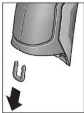
CHIMITE, KaK NOKa3aHO Ha pICyHKe, U-06pa3HyO CKo6y, KOtOpaA cKpePnIeT oBmBky KOpnyCa.
BbIKpyTtBe BnHTbHa Kopnyce n CHHMITE 06uINbky Kopnyca c naHeNbIO KnaBnAtypbl.
ByeepHbI aKKyMylTOp (MHNaTOHbI 3NeMeHT NITAHN) HaxoINTcHa INaTe BHyTpN KOpnyca.BbHbTe erO hKpEnHeHHn cdaTe Ha eKOLOrHuYeCKn uCTyO yTNIN3aCIO.
Bo3MOXHbI H3MeHeHHa.
YkpaIHcbka
Bka3iBkn 3 texhikn 6e3nekn

IpoounTaTe BcI Bka3IBKn I dOtpMnyTecn ix,io6 npaIOBaN 3 BmipOBaIbHM IHCTpymeHTOM 6e3neuHO Ta HadiHb. BHKOPHCTAHNBAHMIPOBaIbHoro IHCTpymeHa 6e3 dOtpMaHnA uX
iHCTpyKuIMoKe npH3BecTH Do NOwKOJxHeHH
iHTerpoBaHNx 3axnCHnx MexaHIm3MIB. HIKON He DOBObTe
nonepdxyBaIbHi Ta6nHKn Ha BmIPOBaHOMy
iHCTpymEtIO HeNbi3HaHHocTi. IO5PE 36EPIGAHTE U
BKA3IBKN I INePDABAITE IX PA3OM 3
BmIPIOBAJIbHM IHCTPYMEHTOM.
06epeXho - BnKOpncTahH3ac06iB 06cnyroByBaHH i HactpoIOBAHH, 0o BiDpi3HJOTbcR B1d 3a3HaueHnx B ciinHCTpykuii, a6o BnKOpncTahHn DO3BOJeHHx 3ac06iB y Heo3BOeHm cnoci6, MoKe npN3BOJHTn Do He6e3neueHx BN6yixB BnPOMIHOBAHH.
BHMipOBaIbHn iHCTpymeHT noCTaueTa63 nonepeJxkyBaIbHOIO Ta6nHcKOIO (Ha 306paXeHHi BHMipOBaIbHO rHCTpymeHTy Ha cTOpIHci 3 MaIOHKOM BOHa No3HaueHa Homepom 7).

KKTonepejkyBaHoiTaNnueKnHeHaMOBIBaowi Kpain,3akneIe Horo neped nepwoEOcnpnyataieIOdoaHOu HAKneKOHOHaMOBIBaowiKpain.

He HanpaBnIte Na3epHn Ipomihb Ha IIOe a6o TBapHH, i cami He nBiTbcHa npamn a6o BiO6paxyBaHN na3epHn npomih. BIn MoKe 3acnHnTI nHux IIOe, cnpuHnHTn Heaachi Bnpank n a60 nowKoNDTH ovi.
Ypa3i notpannnaHHa3epHoro npomeHa B Oko, HABMnche 3anIOuIb oui i BiDpa3y BiBepHITbcra BID npomeHa.
Hiyor He minaHTe BnaepHomy npncTpoi.
He BHKOPHCTOByTe OKyIpyd npo60tn 3 na3epom B kocti 3axncnX okynipB. Okynpi nnpo60tn 3 na3epom npn3Hauehi nKpaIoro pO3ni3HaBaHHa na3epHO npOMeHa, aIe BOH He 3axuiaOTb BiD na3epHO npOMHH.
He BHKOPNCTOBYte OKyIaRn Ia po6OTn 3 na3epom Dna 3axHcTy BiD coHca i 3a KePMOM. OkyIaRn Ipa o6OTn 3 na3epom He 3axNuAOTb NobHicTb Id YΦ- npomHHi noripuoytbo pO3niHaBaHHKoNBopIB.
BidaBaTe CbiB BMIpOBAhHn npnaHa peMOHT nIwe KBaniΦIKOBaHHm faxiBcA m Ta IINHe 3 BHKOpHCTAHm OPrIHAlbHnx 3aunactnH. TlkbN 3a TaKHX yMoB BaW BMIpOBAhHn npnaI iHaanI 6yde 3aIIuATnc 6e3neuHM.
He 03B0nIe dIaTm KOpHcTyBaTHc6e3HaHnAyn a3epHM BmipOBaBbHM npnaJOM.BoH MoKyTb HehaBMncHe 3acnInNTiHnx NIOe.
He npaioIte 3 BmipIOBaIbHMM npHnIaOM y cepeoBnui, de icHye He6e3neKa Bn6byx BHaCNIoK npncyTHOCTI rOIOuHN pIDH, ra3iABo Nnny. Y BmIPIOBaJIbHOMy pINaI MoKyTu YTBOpIOBaTHcI cKpn, BiJAKX MOKe 3aIMaTNC PII a60 napH.
He HanpaBnIte CBITNOBn npOMiNb Ha IIOeN a60 TBaPnH, i cami He DNIBtbcn Ha npOMiNb Na3epa, HabItb 3 BeNHKO BicCTahi.
Ipeyicma MaHInyuaiMa 3 Bmipobabnmpaam (Haep.,MOHTaxem,TexhiuHM 6cnyrobyBaHHMtoo),aTakox npH noTo pahcnopTybaHHi 36epirAHHi BnMaTe aKymaTophy 6atae o a60 6ataeKn i3 npnaNy. Pn HeHaBMCHOMy yBIMKHeHHI BnMkaayichye He63neKa npaHeHH.
He BIDKPNBAIte akymyIaTOpHy 6aTapeIO. IChye He6e3neKa KopoTKoTO 3AmKHaHH.

3axnauTe akymnyTopHy 6atapeIO BID BncoKnx TemnepaTy, HAp., BiTpNbAnx COHnHn npomeHIB, BORHIO, BOH Ta BOIOrn. IChyE He6e3neKa Bn6yxy.
36epiraTe akymyIaTOpy 6aTapeIO, IO came He 3aCTOCOBYcBcH, BiDAnIK BiI KaHcEJIpcbKHX CKpINOK, MOHeT, TBnHTiB Ta iHnIX HeBENKHX MeTaeBnx IpeMMeTiB, IO MoKytB CnpNHyTH NepeMKHeHHKOHTaKTiB. KopOTke ZAMKaHH MIX KOHTaTKaMn akymyIaTOpHOi 6aTapeI MoKe Ipn3BOdHTn Do onIKy a6o noXekI.
- Pn HnepaBnBbHomy BnKOpNCTAHHi 3 akymyIaTPOHoi 6batae moxe BnteKTH pIDHa. YHHKaIte KOHTaKTy 3 HeIO. Pn BnnaKOBOMy KOtAKTi npomHite BiNoBiDne Micu BoIOIO. Ako piINHa notpanHnBa Oo,doaTKOBO 3BepHITbcr do Iikapra. PdHa, zo BVTeKNa i3 akymyIaTPOHoi 6batae, M0ke BnKlnKaTH nOpa3HeHHa shkpH aOximuiOnIKn.
Pn nowkodkeHHi a6o HnpabHbHomy BnKOpctAHHI akymyIaTOPHOi 6atapeIMOKe BHXoDHTn nap. BnyctITb cBKe nobitpr i-y pa3i ckapr-3BepHITbcdo nikapra. Nap moKe BnKnKaTn noPa3HeHHaXaIbHnx IJxABX
3apJxAteakymyTophi6aTapeiHnueB3apJHX npncTPOX,IO peKOMeHDOBahi Bnpo6HnKOM. 3apJHHpncTpiMOKe 3aMAtNC,AKUO B HbOMy 6byt 3apJxKatNCHepeE6aueHi akymyIaTOpHi 6atapei.
BHKOPNCTOByTe aKymyIaTOp IInWe pa3oM 3 qIM iHcTpymentom Bosch. IInWe 3a TaKnx yMOB aKymyIaTOp 6yde 3axnueHH BId He6e3neuHoro nepeBaHTaXeHHA.
BVKOPNCTOByte NHwe opnHahbHi akymyIaTOPHI 6atapei Bosch 3 HanpyoIO, 0IO biINOBiJaE daHm Ha 3aBoDcbKiI Ta6nUci Baworo BHMipIOBaIbHor npnaAdy. PnBVKOpNCtAHHI iHNHX akymyIaTOPIB, HAp.. nIpOboK, BiHOBneHx akymyIaTOPIB a6O akymyIaTOPIB iHNHX BInpo6HKnIB, iChYc He6e3NeKa TpaBM Ta NOsKOJKeHH MaTePiAlbHnx ciHHocTei BHacJIIDOK Bn6byxakymyIaTopa.
TocpHmnpedMeTamn,Hanp.,rBizdkamn a6o BHKpyTkamn,a60 npKladaHnM 3OBHihboi cnn MoJHa noWkoDHTn AkymyIaTOpHy 6atapeio.MoJInBe BHyTpIshE KopoTke 3AMKaHH,3aRopHH,yTBopeHHa Dmy,Bb6yx a6o nepepiB akymyIaTOpHO6atapei.
06epexho!PnBHKOpncTahHINBMIpOBAhBOI hCTpymEnTy 3 Bluetooth® moXnBi nepeWkoDi nIinHnx npnaIb i yctAHOBOK, nIaKIB i MeuunHcbKnAnapatIB (Hanp., KapioctHMnyAToPiB, CnyXOBHX anapatIB). Kpm TOrO, He MOxHa NOBHCIO BVKNIOUHTN MoXnBIcTB 3ABDaHHa WKOdN IIOJAM I TBAPHHAM, 3HAxoJrTBcB B 6e3nocepeHni 6n3bKocTi. He KopnCTyTEcB BMIPoBaJIbHIM IHCTpyMeTOM 3 Bluetooth® no6n3y BiM MeuunHcbKnAnapatIB, 6EH3OKoONOHok, XIMiHnx yCTAHOBOK i TepHTopi, Ha kNx icHyE He6e3neKa B6yXIB a60 MoKytB npoBoNTnCpiDpHBi p60TH. He KopnCTyTEcB BMIPoBaJIbHIM IHCTpyMeTOM 3 Bluetooth® B nItaKax. HamaraaiTeCHe BMHKATn IHCTpyMeHT Ha TpNBann Yac 6e3nocepeHbo KOLO tina.
CnoBecnH TOBAPnH 3nak Bluetooth® i rpaΦiuyHi TOBAPHi 3nAKn (Iorotnn) cTahOBnAytb c6oIO 3apecCTpOBAhi TOBAPHi 3nAKn i E BnAcHicTIO Bluetooth SIG, Inc. Robert Bosch GmbH BnKOpncToBye ci CnoBecHi/rpaΦiuyHi TOBAPHi 3nAKn 3a IiueH3ieIo.
Henk Becker Helmut Heinzelmann Executive Vice President Head of Product Certification Engineering PT/ETM9

Robert Bosch GmbH, Power Tools Division 70764 Leinfelden-Echterdingen, GERMANY Leinfelden, 16.04.2015
MoHTax
JKepeNo JKNBneHn
BmipobalbHH iHctpymeHT moKe npauoBaTH BID 3BnuaHnx 6atapeyoK abo BiD niiEBO-ioHHOi akymyIaTOpHOi 6atapei Bosch.
ApTkybHn Homep 3601 K83 370:BmipIOBaIbHn IHCTpyMeHT DO3BOJAEbCBAKOpHCTOByBaTH IINHe 3I 3BvauHmN 6aTapeKamn.
EknpnyatauaB iD 6atapeoK (Kpim TOBAPHOrO Homepa 3601 K83 370) (nVB. Man.A) 6atapeiKn nOtpi6Ho BCTpOMnTu y nepexiHNk dna
IpeexiHnK d7 6aTapeoN np3HaueHn BnKnHouHo IINBHKOpNCtAHH3 nepe6bueHm d7 zuoro BHmipOBanbHMn IHCTpyMeHTAmn Bosch,i noro BHKOpNCtAHH BeneKTpoIHCTpyMeHTax 3a60pOHaETbcra.
Uo6 BCTaBHTb 6batapeKn, NocyHbTe Koxyx 27 nepexidnka dIa 6batapeNOK B cekuio Ira akymyIaTOpHOI batapei 29. BcTaHOiB 6batapeKN BiINOBiHO IO MaIIIOHky Ha KpHsi 28 B Kopnyc. HacyhBe KPNsKy Ha Kopnyc, NOKI BOHa He 3aJe BIDyTHO y 3auePENHeHH Ta He 6yde 3HaxOHTncBpBeHb 3 pyKOaTKoIO.
Lio6 BnHHTn 6batapeKn, HATNCHITb Ha KHOKN p036NoKyBaHHa 3 KpnKn 28 i3HIMtB KPNKy. Pn bOmy cniKyIte 3a Tm, 1o6 6batapeKn He Bnann. Tpmaite IHCTpyMeHcuiEIO dna akymyIaTOho 6bapei 29 DorOpn. BnMiTb 6batapeKn. Lio6 BnHHTn po3aUOBaHN BCEpeHHi KoxyX 27 i3 ceKuII dna akyMnyIaTOho 6bapei 29 Bi3bMIbCra 3a HbOrO i BnMIb IHOr 3 BMIPIOBaIbHOro IHCTpyMeHTy, 3nerKa HATNCKAQUH Ha 6OKoby CTINKY.
3aBxMnMiHHeOndHouacHO Bc6atapeKn.BKOpNCToByTe Nlne 6batapeKn OndHoro Bnpo6Hnka i OndaKaBOi EMHOCTi.
BnMaTe 6aTapeKn, AKnO Bn TpHbAHH qac He 6yTe KOpNcTyBaTHCBAHMIPOBAbbHM pHnaDom. Pn TpBaIOMy 36epirAHHi 6aTapeKN MoKyTb KOpOyBatn i camOp03PraJxatncr.
Ekncnnyataia BID akymyntopho6taapei (kpim ToBapHoro Homepa 3601K83370) (mB. Man. B)
Bka3iBk: BnKOpNCTaHHa akymyIaTOpHoi 6batapei, 10 He niiXoNTb do BaWoRo BmIpIOBaIbHOro iHcTpymeHTy, MoKe np3BeCTn Do 36oIB B po6oTi a6o NOnKoJxehn BmIpIOBaIbHOro iHcTpymeHTy.
Bka3iBka: AkymlyaTopHa 6aTape noctaaetbca yactkoBo 3apJKeHO. Uo6 akymlyaTopHa 6aTape 3moIpaeani3yBaTH CBOIO NOBHy EMHICTb, nepei nepShIM BHKOpNCtAHnM eNEKtpoiHCTpymEtY II Tpe6a NobHicTo 3apJNTN B 3apJNDHomy pInCTpoI.
BHKOPNCTOByTe NHwe 3apAHi npnctpoi, 0o 3a3hauehi B texhivHnx daHnx. Nlle Ha ci 3apAHi npnctpoi po3paxoBaHni liTii-IOHHn akyMylrTOp, 0o BHKOPNCTOByeTbCra y BaWOMy BmIpOBAIbHOMy IHcTpymentHi.
IitieBO-IOHHy akyMnyTOpHy 6batapeIO MOxHa 3apJxATN KOH 3aBROHO, ce He cKopouye II ekCnIpyatauIHn pecypc. IpepeINBaHHn pOuecy 3apJxAHn He noiKOJxUe akyMnyTOpHy 6batapeIO.
■nicra ABtOMaTHUHO RBMHKaHHB MIMIPoBaIbHoro IHcTpymEny 6iNbHe He HaTCKyIte Ha BMnKau. Lc MoKe NpOkoHTn akymyIaTOphy baTapeHo.
Iio6 BCTpOMHTn 3apJxHn aKymyTOp 30, npocyBaTe Ioro y cekzIO nla akymyTApHO batapei 29, nOKn BiH ne 3aJe BIDuyTHO y 3auePHeHH Ta He 6yde 3haxoNTncr BPiBHe 3 pyKOATKOIO.
Ioo6 BnHnTn akymyIaTOp 30,HaTNCiTb Ha KHOJKN po36noKvBaHH 3 i BnMIb akymyIaTOp i3 cekii IIN aKymyIaTOpHOI 6aTaPei 29. He 3actocobYte npuCbomy cnny.
EknpnyatauB iD 6atapeHok (3601K83370) (nVB.Man.C)
Iio6 BiKpHTN KPNKU cekii dIy 6aTapeiok 31,HaTNCiItb Ha KhoIKN pO36nOKyBaHHra 3 i3HIMITb KPNKU cekii dIy 6aTapeiok.
PⅡI yac BCTpOMnHn 6batapeiOK cnIDkyTe 3a npaBnIbHOIO nOJIphHcTIO y BiINOBiHocTi DO MaIIOHky Ha KpnUci cekii IJRA batapeiOK.
3HOB HadiHbTe KpnuKy cekuii dna 6aTapeNoK 31 i daIte II dyTHO yBiIny y 3auenneHH.
3aBxM iHnTe OHOuacHo Bc6batapeKn. BkOpncToByte JIiue 6bataeKn OHDoro Bnpo6hNka i OHaKOBoi EMHOCTi.
BnMaTe 6aTaepK, Ako Bn TpHbann qac He 6ydeTe KopncTyBaTcBnMipIOBaIbHm npnaDOM.
PnTpBAnomy36epirahHbTaapeKMOxytb KopoDyBaTu i camOp03paJkaTncr.
IIndkaTop 3apdKeHocti
IIndkaTOp 3apJxKeHocTi gHa DnCnIe NOBIDOMJIe 3apJxKeHicTb 6atapeiOk aOaKymyTota 30.
UHM Kpaui Ta ctabiBhiWi yMOBN BmipOBaHH, TMM TOHiiTa HnHniPi pe3yNbTaTN BmipOBaHH.
DaTnK BONORCTI NOBITP I TEMNepaTyPi HABKOINHbOre cepeOBuHa 5 MoKe noWKoNDtncAYepe3 XIMiHy NiKIDnBi peOBUHH, HApP., BInapOByBaHN NaIK a60 ap6. Ha BVMIpIOBAHH TeMNEpaTyPi B IHΦpauepeBOHOmy CneKTpi MOxYb HeRaTHBHO BIIINHYdM, Napa a60 3aJIInHe nobITPra.
Yepe3 Te y BnnaKy BmipIOBaHb y npMlueHHx Heo6xJHO npoBITpIOBaTH IX nepeB BMIPIOBaHHaM, OcO6NBO KOnn NOBITpr 3abpydHehe a60 dyke 3anapObaHe.
Iicn npoBipTOBaHH 3aueKaTe Deekn Yac, 06 Tempepatb B npimuiHHi cta6iN3yBaIacr i3HOBy DoCraHa 3BnuayHOrO NOKa3Hnka.
TemnepaTpaHa HbKoHnHbOro cepeOBuca i BiHocHa BONiCrTb NOBITpBaBMIpIObC86e3NocepeHbO Ha BmIPBOBaHOMy IHCTpyMeHTI 3a DOnOMoTO DaTuNkA temnepaTpHa HbKoHnHbO ro cepeOBu7a5. Uo6 OtpMaTH IO6pi pe3yNbTaTN, He TpMaHTe BMIpIOBaHbHIn IHCTpyMeHT6e3NocePeHbO NaI a60 npuy 3 dJxepenAmn IpeewKOd, TaKHMn Jk npinadn OanaleHHa6o BiKpnTi pIDHN.HIKOHN He HAKPBAte DaTuNK5.
BmipuBaIbHi FyHKcii
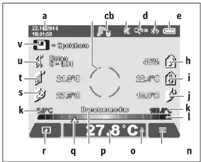
Ctanhapthe 3o6paekennhaekpani
a Data/ucac:INB.«Uac/Data»,CTop.259
b BmipioBaIbHa paMa: nB. «ПIoUa npN BmipioBaHHi Tempepatyn nobepxHi》,CTop.255
CINdNKaTopCTaHy:

BmipobaHn iHctpymeHT roTOBn DO BmipobHH,HaTCHiTB KhoNky BmipobHH 4. 3iChIOeTbCra (TpBaIe) BmipobAHn,na3epn yBIMKHeHi.

BmipobHn 3aBepHe,naepe BmKHeHi, pe3yIbTaTn BmipobHn 3aqiKcObaHi.
d INHnKaTOp 3ByKOBOrO CnHany BmKHeHn (INB. «3ByKOBn CnHaJn》,CTop.259)
e IHdNKaTOp CTyNeHr 36iNbWeHHr: NIB.《HanaWtYBaHHrCTyNeHr 36iNbWeHHr》,CTop.254
f IIndkaTop Bluetooth® yBIMKHeHn (ДИВ. «ПepeDAчданнх поBluetooth®»,стор. 259)
g |HДиКaTOp 3apДжKeHocTi:ДИВ.«|HДиKaTOp 3apДжKeHocTi»,стop. 253
h INdkaTop fYHKuii/BnMipIe 3HaueHHB iDHoCHOI BONOROCTIOBITPR
i IINKAtop fYHKui/BmipIe 3HaueHH TaMepeatypn HaBkONHbOro cepedOBua
j IHnKaTOp fynKuPi/Pe3yNbTaT BuHaueHHeToUKN pOCH
k MIHimalbHe/MaKcHMaJIbHe BIMIpIe 3HaueHHa TemnepaTyPi NOBepxHi NiD ac IpOecy BIMIpIOBaHHa
山kapezynbtaTIB
m CnmboJ MeHIO
n IHNikatop CnHnIi3aui TemnepaTyPi NOBepxHi; nIB. «CnrHnIi3aiaj TemnepaTyPi NOBepxHi», CTOp. 257
Bmipnhe 3haeHH BmipHOBaHH TeMnepaTpyn nobepxhi
p NOTOuHn peXHM po60Tu
q N03haquKa BmipraHoro 3HaueHHa 6pe3ynbTaTy (3aneKntb BiD o6paHoro peXnMy p6oTn)
r CmBON ranepei
5 INdkaTop yHKii/BmipraHe 3naueHHa cepenHbOITemnepaIpyn
t IHdNkaTOp fHyHKiB/BmipRHe 3haueHHaTeMnepaTyPn KOHTaKTo
U INDnKaTOp KoephiicHTa BInpPOMiHOBaHHA
v CmB0n 36epexeHHN
Okpeme BmipioBaHHa
OdHM KOpOTKHM HaTNCaHHM KHONKN BmIPIOBAHH 4 yBIMKHITb Ia3ep i 3anyciTb OOnHOue He BmIPIOBAHH B o6paHomy pexnmi po6oTN. TpMaIte HApPaBHeHn Ha o6'cKT BmIPIOBAHH BmIPIOBaIbHn IHCTpyMeHT HepyXOMo, nOKn He BiO6pa3Ntbcra BmIPJe 3NaueHH. Ppoec BmIPIOBAHH MoKe TpNBaTI Do 1 cekyHn.
IIO 3aBepWeHHI BmipIOBaHHJa3epn aBTOMaTHHO BmIKaIObCra. Ha IncPiEi 3'RBnAIObCpae3yNbTaTH BmipIOBaHH.
HaTnCHiB KhONKy BmIPoBaHHa 43HOBy, 06 po3nooyaTH HOBe BmIPoBaHHa iHaAHToBaHMM npaMeTpamn BmIPoBaHHa.
Tpmbane BmmpioBaHHa
ДлгТРИВАЛOROBIMIPIOBAHнуобpaHOMу pexHMI TrpmaIte KHOKNy BIMIPIOBAHн4HaTNCHeHIO.Ja3epn 3aIIHuaOTbCSYBIMKHeHmPyXaOuHcNb NobInbHo, cnpaMOByTe Na3epHI TOUKNNo Yep3i Ha yci NOBepxHi, TempepatypЯKnx XoueTe BIMIPrTH.ДлгВIMIPIOBAHнBOIrorocti I Tempepatpyn HABKONlWbHorO cepeDObNua NOBInbHo NOBODTe BIMIPIOBaJIbHm IHCTpyMeHTOM y npMlIeHHI.
IHNKATOpHnHaDnCnEiNocTInHO OHOBIOJTOBcR.KnTbKN KhoNk BmIPIOBaHH46yDe BiDnyUeHa,BmIPIOBaHHn nepePnBaTeBCraIJa3epn BmMnKaHOtbcR. HaDnCnEi IKCYOTbcrOCTAHPiPe3yNbTaTH BmIPIOBaHH.
HaTnCHiB KhONKy BmIPIOBaHHa 43HOBy, uO6 po3nooyaH HOBe BmIPIOBaHHa i3 HanaSTOBaHHMn npaMeTpamn BmIPIOBaHHa.
36epexehn/bo6paXeHHBipnpaBHeHHpe3yIbTaB BHmipIOBaHH
IIO 3aBepueHHI BmipIOBaHHHa IINcPNei BiO6paJAcTbcnMBOI 36epeKeHHa V BAKoCTi INdkatopa TOrO,IO pe3yIbTaTH BmipIOBaHH MoKHa 36epeRTH.ДЯцboro HATNCHTb KONky 36epeRTH/BiINpabNTn 9.
Pe3yNbTaTN BmIpiOBAHn 36epiRaIOBcR y BnIaI daIIaJ. JPG (3HIMOK ekpaHa Dncnner, Ioo oikcyetbcR).

-Дя BiO6paXeHHa 36epXeHHx 3HIMKIB ekpaHa HaTNCHTb NBy FyHKIOHaIbHy KHOKy 17 niCnBONom ranepei r. Ha nCnnei 3'ABNCTcOCTaHHI 36epXeHHn 3HIMOK.
HaTnCKaIe KhoNk3i CtpiKamn npaBopyu 11 a6oJIbOpyu 15, u6 nepexoHTn mIX 36epexeHmN 3HIMKaMn ekpaHa.
- Ⅲo6 BiDnpabHTn BiO6paKyBaHi pe3yIbTaTH BmMIPIOBaHHNo Bluetooth®HaTNCHTb KHOJ Ky 36epeTTN/BiINPaBHTN 9. JkIo 3'cHAnHHaBluetooth® ue He BCTaHOBHe (INB. «IpeepaDaHnx no Bluetooth®», cTOp. 259), BOHO AKTNByCTbC HATNCKaHHa M KHONKn 36epeTTN/BiINPaBHTN.

- Ⅲo6 BndaHHTB iDobpaKyaBaHn 3HIMOK ekpaha,HaTNCHTb npaby fYHKIOHaIbHy KHOJky 10 NiD CmBBOJOM CMITT.

-Дяптбердженин Виален,Натсит bIbyФункцioHaJIbHyKhoNky17NiI raNoUkoIO.

Дя BiDiMHn BndaIeHHa,HaTncHtB npaByФунkuioHaNbHy KhoNky 10 niJ xpecrKoM.

- Uo6 BnHTn 3 npedctabHeHra nepeei i nobepHyTnCdo peKmBy BmIpIOBaHHa,HaTCHiBIbY cyHKcioHaJIbHy KHOJky 17 niD CnMBOIOM Ha3aI.
Bci 36epekehi paHIM MOxHa BnIaHTN 3a OndHM 3axoDM.
DIB.npo ue *BnIaHTN yci 306paKeHHra", cTOp.260.
PexHM Temnepatypn nobepxhi
BpeKIMI TemnepaTpy nobepxhi Bmipioetbca TemnepaTpa nobepxhi 6'ekTa BmipioBaHH.
B zubomy pexnmi po60tn moxha, hamp., wykaTH neperpiti 3anobixHHKn a6o Tpy60npoBOn DNaJIeHHN y npraoyiBoHn.
L6 nepemkhnytncypeXHM BmipIOBAHH TEMepaTyPi NOBepxHi, NOBepHITbcR, kkuo nOtpi6Ho, do cTaHApTHO 3O6paKeHH Ha ekpaH. NotIM HATnCKaIte KhoNKy 3i CTpiKIO IO npabOpuy 11, NOKn HE BiO6pa3HTBCBIKHO «Temnepatypa nobepxHi> 3 KOPOTKM IORcHeHHM peXmY po60TH. L6 3aBuacHO BmKHyTN IORcEHHH, HATNCHTb KHONKY 36epeXeHH 9.
L6 BmMKHyTN IORcEHHH i Ondpa3y po3noTuB BmIPBOAHHH, HATNCHTb KhoNKy BmIPBOBaHH 4.
HaTNCiB KONky BmipIOBaHHa 4 i cnpMyTe BmipIOBaHbHn IHCTpyMeHT BeptKaNbHO Ha cepeHNy 06^ kT_a BmipIOBaHH. Ito zakIHueHHI BmipIOBaHHa IHINkAtopi o fikcyetbc TEmpepaTypa NOBepxHi OCTAHHbOrO UINbOBOrO 06'KTa BmipIOBaHH.
YBnnaKpy TpNBaIoro BmipIOBaHHN OCTaHHBmIPraHa TempepaTpa NOBepxHi BiOobpaKaeTbCn PO3NaUKOq Ha Shkani pe3yNbTaTIB I. MinImaJIbHe i MaKcHMaJIbHe 3NaueHHa Tempepatyniuc npocuepny BmipIOBaHHa BiOobpaJyOTbcn Ha INDnKATopi k, RaTINbKn p3HNzMix BmIPraHHM 3NaueHHM NpeBnUyE 3°C. TaK MoXHa BN3HaunTH, HacIKbKn BnCOOKM E NOTOHe BmIPraHE 3NaueHHN IO BInHOseHHIO DO BXe BmIPraHHX TempepaTyP.
CnHnlaiaqia Tempeatypn nobepxhi
CnHnI3aui Tempepatypn nobepxhi MoKe BnKOpNCTOByBaTncB ycix pexkImax po60tn. MoKHa 3aatm MinImalbHy I MaKcMmaIbHy Tempepatypy.
Akuo TemnepaTypa Hxka 3a MinimalbHy TemnepaTypy, iNikatop cnHani3aui TemnepaTypn n 6nImae CnHim, a npu yBIMKHeHomy 3ByKObOMy CNHaJI NyHae 3ByK nonpeJKeHH.
JaKIO TeMnepaTpya Bnla 3a MaKcHMaIbHy TempeaTppy, iNdkatop CnHaIi3auii TempeaTpyn6IImaE cepBOHM i npn yBIMKHeHomy 3ByKObOMy CnHaI lyHaε 3Byk nonepdJxehn.
IooB BnKOpNCbOByaTn CnHaii3aio TeMnepaTyPi NOBepxHi, nepeiTiB do «FOnOBHO MeHO» (INB. «HaBiraia B «FOnOBHomMy MeHO»», CTop. 259).
-06epiTbPiIMeHIO(ΦyHKUII)
BcTaHOBiTb《CnHraI3auiaiMin/MaKc》Ha《yBIMK.).
- YnyHKTI «ChrHani3auiMn» 3aaiTe MiHaMbHy TeMnepaTpy.
- YnyHKTI «CnHani3auiMaKc» 3aJaTe MaKcImaJIbHy Tempepatypy.
Mimimabha i makcmaiba TeMnepaTpya TaKoX 36epiraIbC8, KOJI CNIHAni3aui BCTaHOBIOEbCra Ha «BHMK.»
Bmipobahn TemnepaTy KOHTAKTy
B MeHIO MoBaMoXHa 3mIHHTMOBy ycix IHnKaTopiB.
- Yac/Data:
ДязMHидп iucуHa iHdkaTopi apeeijtBdo NiIMHeIO «Yac iData».ВцbOMy niIMeHIO MOxHa TaKox 3MiHHTnФopMat dATi iucy.
Lio63aannnpiinmeHIO《Yacida》,HaTNCHTb aO nIbyfynKIOHAInbHy KOnKy 17 nIraIooukoIO,o6 36epeRTnHanaWtYBaHH, a6o npaby fynKIOHaInbHy KOnKy 10 nIdxpectNKOM,io6CKacyBaTH 3mHn.
-ODHHN4A:
B MeHIO «OdHHNua» MoXHa 06paTH, YN Bka3yBaTH TemnepaTpy B «°C» a6o «°F».
- 3ByKOBn CnHnA:
B MeHIO «3ByKOBi CnHannMoXHa yBIMKHyTN a6o BnMKHyTN 3ByKOBn CnHaN, IIO lyHae npu CnHani3aui TEMpepaTpyn NobepxHi.
BmipioBaIbHa paMka:
B MeHIO «BmipOBAIbHa paMa» MOXHa yBIMKHyTn a60 BmKHyTn BmIPIOBaIbHy paMky b Ha DCnIeI.
- KonbopoBa cxema:
B MeHIO «KoNbopoBa cxema» MoXHa 6paTH,ЯKM KOnbOpOM BiO6paxKaTHMyTbcr 3HaueHHa TempepaTyPi Ta iHwi NOKa3HNi HaIcnPnei. Lc HalaWtYBaHH npHMaTeBcra TAKoJ dRn 36epeKeHXx 3HIMkIB ekpaHa.
- YacBMMKahHHa:
B MeHIO 《Aac BmHKaHHa MOxHa o6paTH qacOBn iHTepBaI, nICrJa KOrO BmIPIOBaIbHN iHCTpyMeHT aBTOMaTHUHO BmHKaCTbcR, RaIcO He HaTCHyTa XoJHa KHONKa. ABToMaTHuHE BmHKaHHa MOxHa TaKOK DeaKTbByaTH, O6paBShn HalaWtBuHHa «HikOnN». UHM KOPOTWe yac BmHKaHHa, Tm 6IbWe MoxHa 3eKOHOMHTeheprii.
Tpnbanictb niicbiuybaHHa:
B MeHIO «TpnbaniCt b nicBiyBaHH» MoKHa o6paTH yacobn iHTepBaI, nICrJaKO rCKpaBcTb nIDCBiCyBaHH IINCIe 3MeHwEbCra, RaKIo Ha BmIpOBAIbHOMy
iHCTpyMeHTI He HaTnCKaCtBcRA XODHa KHONKa. IIncnneJ MoXHa TAKoK NiDCBIuYBaTH 6e3nepepBHO, O6paBShn HAJIaWtYBaHHA «3aBXKnU. UIM KOPOTwe TPNBaNICTb NiDCBIuYBaHHA, TmM 6inbSe MOxHa 3eKOHOMNT eHepriI.
Bndaunntyci 306paXeHHa:
B MeHIO «BnDAnHTN yci 306paXeHHa» MoKHa 3a ODNHM 3axoDM BnDaJIHTN yci faai, IIO 3hAxOJaTBcRy BHyTpIiHiN nam'AtI. HATNCITb KHOKNy 3i CTrpIKoIO npabOpuy 11 106 nepeTn Do nyHKTy «dani ...», i NOTpAnHTN do NiMeHIO. Notim HATNCITb a6o liBy YHKQIOHaJIbHy KHOKNy 17 NID ranoKIOU, 106 BnDaJIHTN yci faai, a6o npaby fYHKQIOHaJIbHy KHOKNy 10 NiD xpeTnikom, 106 uei npocec ckacyBaTH.
- Ihfoopmaizipno BmipioBaIbHH IHCTpyMeHT:
Дя OTрманнг iHфорmaцii npo ВИМIPIOВаьнIHCTpyMeHT npeeDITbdo NiIMHeHIO «IhФopMaicn npOBmIPIOBANbHn IHCTpyMeHT. TaM 3HaXOДТСЯ cepiHnH NoMEp BmIPIOBaNbHOr iHCTpyMeHTa I BepciBCTaHOBNeHOrI nporpaMHOrO 3a6e3neueHH.
HenonnaKn - npuunH i ycyHeHHa
Texhue o6cnyroByBaHHiaounHn
36epiraTe i TpaHcnpTyHe BVMIPOBaIbHn iHCTpMeHT NIIwe y npdaTHOMy KOHTeHepi, HAp., y opurIHaBHi ynaKoBuCi a60 3axncH cyMu (npHaJd). Hanpknad, Ha 36epiraTe Ioro y pNaCTIKOBOMy nakeTi, BNapOByBaHHraKOro MOxyT b NOxKDnTH DaTuHK BONorOci NobITpr i TemnepaTpHy HABKOnHbHO rcepeOBuCa 5. He HAninIOte 6yDb-ki HAniINKn No6n3y daTuNka Ha BVMIPOBaIbHn iHCTpMeHT.
He 36epiraTe BmipIOBaIbHn IHCTpyMeHT TpIbIaN qac 3a Mekamn BONorocTI NOBITpR BID 30 do 50% .Akuo BmipIOBaIbHn IHCTpyMeHT 36epiraetbcra B 3aHaTTO BONORmy a6o 3aHaTTo cyxomy cepedobu,ue MoKe Ipn3BeCTn Do HnpaBINbHnx BmipIOBaHb Pn KOpNCtYBaHHi IHCTpyMeHTOM.
3aBXKn TpMaIe BmIpOBAIbHn npnad B YnCTOTi.
BHTpaTe 3a6pydHeneHH BONTOIO M'koIO rAunipKOIO.He KopnctyIteCMAHMMN 3ac06amIpO3uHHNKAMN.
PnOuHHeHHI BmipOBaBHO iHCTpyMeHTy HbOTo He NOBHHa npOHKaTH piHa.
Oco6nBO o6epexHo ouHnyTe daTukB OlorocTi nobitpr i tempeatpyn HABKoHshbOro cepeobuia 5, kamepy 22, npHOMHy nH3y 23, liXtap 24 i BHXiHi OTbOpn dIra na3epHoro npomehr 2:
cnikkyte 3a THM, uo6 Ha Kaempi, npinomnhi nih3i a60 BHXIDHIX OTBOPAX dIy Ia3epHO rpoMeHr He 3aIIuAIOcK JODHIX BOPCHNOk. OunuYTe Kamepy, npinomHy iIN3y i BHXIDHI OTBOPN dIy Ia3epHO rpoMeHr NIIe 3acO6amn, kI npndaTHI dIy UIe HNr IIN3 fOToanapatIB. He HamaraITecB INaJIaTNIb 6pyd 3 daTUnKa, Kaempi A60 npinomHOI nIH3n 3a DOnOMOrTO IOCTpIX NpeDMETIB IHe CTnpaiTe 6pyd 3 Kamepi I npinomHOI liHN (he6e3neka yTBOpEHn NOprpnnH).
BipnpaBnTe BmipOBAIbHn IHCTpyMeHT Ha peMOHT nWe BOpriHaIbHi ynakobci a6o 3axnci cymci (npnaD).
Cepbic Ta HadaHna KOHCyNbTaCii 0oDo BHKOpNCtAHn npOdyKcii
CepBicHa MaNCTepHbIINOBiCTb Ha 3aHTaHHCTOCOBHPOemOnTy I TexHiHoro 06cIyROByBaHHBaUoro BnOby.
MaHONKINB DeTAnX iHΦopMaIIO ⅢOo 3aNuaCTNH MoKH3HaHTn 3a aDpecoI0:
www.bosch-pt.com
Komahna cniBpO6iTHNKiB Bosch 3 hanaHHa KOncIbTaui JIOdo BnKOpNCTAHn npOykuii i3 aIOBOJeHHa BiNobicTb Ha Bawi 3aHTAHn CTOCOBHO haoi npOykuii Ta npInaJaDo Hei.
При 6уд-якх 3aитаннх i 3aMOBлeнHi 3aIuactH, 6уд laacka,обов'язКОВо 3a3HaayTe 10-3HaayHn TObAPHn Homep,ю 3HaxOДNTbCЯ Ha 3aBOdcbKiŋ Ta6lnuci BIMIPIOBaIbHOr npInaIy.
TapaHTiHe O6cnyROyBaHHI pEmoHT eJeKToPiHCTpyMeHTy 3dInCHIOHO BIDIOBIDHO BO BHMOr I HOPM BNTOBNIHOBAa Ha TepntopII BCIX KpaIH Nnwe y fipMOBX a60
ABTOPIN3OBAHnx cepBICHNX CEHTpax fipMN «Po6epT BoW>.
PONPEJXEHH! BHKOpNCTaHHK ONTPaKaTHOIpOdyKuII He6e3neueH B EKcNpyatauii i MOxE MaTH HeraTHBHi HAcNiDKN dna 3dOpOB'. BnroTOBNeHHI ipO3NobCIOJKeHHa
KOHTpApaKTHO IpOdyKuII nepeCNIyETbCR 3a 3aKOHOM B adMinHicTpAHBOHY i KpIMHaJIbHOMY nopRky.
YkpaHa
TOB «PôbepT Bòu»
CepBicHn ceHTpeEeKtpoIHcTpyMeHtIB ByI. KpaHa, 1, 02660, Knb-60 YkpaHa
Ten.: (044) 490 24 07 (6araTOKaHaIbHnI)
E-Mail: pt-service.ua@bosch.com
OphiuiHn caH: www.bosch-powertools.com.ua
Adepeca PeriohaJIbHINx rapaHTiHINx cepBICHNX MaIcTepeHb 3a3HaueHa B HaioHaJIbHOMy rapaHTiHOMy TaHOHi.
TpaHcnpTyBaHHa
Ha BnKOpNCToBvBaHni NiTiEBo-IoHHi AkymyIaTOpHi 6aTaapei
po3IOBcIOJxOyOTbc npNnCn OIO TpaHCnOpTyBaHH
He6e3neuHnx BaHTaXIB. AkymyIaTOpHi 6bataep MoKyTB
peBcO3NTnc KOpCTyBaUem ABTOMbHM TpaHCnOPTOM
6e3 Heo6XiHDocTI BnKOHAHN DOJaTKOBHX HOpM.
Ppi nepeCnUti TpetIMN OC6Amn (Hanp.: NobITpaHMM
TpaHCnOPTom a6o CnAAMn TpaHCnOPTHO EKCneDHTopa)
NOTPi6Ho DoepKByBaTHc OOC6nNBx BmOR IOo YoNAKOBKn
Ta MapKByBaHH. B UcbMy BnAaKy npri NiIdroTobci NocnKn
NoBHeH npHMaTHu yAcTB ekCnept 3 He6e3neuHx
BaHTaXIB.
IpeceHnaiTe akyMnyaTOpHy 6aTapeoNlleB TOMy BnnaKy, Raio Koprnyc HenoWkoJKeHni. 3akneTe BiKpnti KOHTaKTNa Ta 3anaKyte akyMnyaTOpHy 6batapeo TaK, 06 BOHa He COBaIacB ynaKOBuCi.
IOTpMMyTEcA,6yNbJaCKa,TaKoX MOKNBHX DoaTKOBNX HaioHaJIbHNx npnnciB.
Ytunizaia

Bmipobbhi iHctpymeHTn, akymyIaTOpn/6aTapei, npnaia i ynakOBky Tpe6a 3daBaN Ha ekONorIuHO uNCTy NOBTOpy nepeoKy.
He BnKnaIte BnMIPIOBaJIbHI IHCTpyMeHTu aKyMyJIaTOpHi 6aTapei/6aTaepeN K N o6yTOBe CmTTI!
Jnne nKpaH EC:
BidnoiHNO IO eBponeNcboKIO dHpeKTNB 2012/19/EU Ta eBponeNcboKIO dHpeKTNB 2006/66/EC BIDnpaOBoHaBI BMIpOBAIbHI npnAIN, noWKOJKeHI aBO BIDnpaOBoHaI akymIaTOnHi 6atapei/6atapeeKn NOBHHI 3daBaTHcA OKPeMo I yTNl3yBaTcra ekONorIHNo uHCTHM cNoCobom.
AkymnyTopn/6atapeienKn:
JitieBO-ioHHI:
Bynb nacka, 3BaKaIte Ha BkA3iBKN B po3di «TpaHcnpTyBaHHa», ctop. 262.
IHTerpoBahi akymyIaTOpHi 6batae i03BOJIcTBc BnMaTH IInue faxiBzM i Inue dny ytni3aui. Ppr BiDKpNBaHHI 6uWNKn KOPnyC moKlNBE NOWKOJKeHHBnMIPOBaHOro IHCTpyMeHa.
I06BnHn76yepnN nii-nioHHn akymyTOp 3 BmipBoaHOro IHcTpMeHa, cnoatky BnMItb aKymyTOp 30 a6o nepexiHnK dJa 6aTapeNoK. 3HIMtB 3axnche cKnO 3dncnne, a Notim KnaiaTyPhy naHeb.
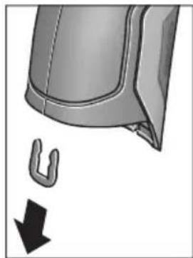
3HIMITb, JK Bka3aHo Ha MaIIOHKy, U-nOdi6Hy cKO6y, Jka TpMae pa3OM oboONkY Kopnycy.
BnKpyTb rBnHTn Ha Kopnyci 3HIMtB o6oNoHky Kopnycy i3 3aBOcboKOIO Ta6nUko.
Byeepn akymyaTOp (MIHaTOpHn enemt KMBHeHH) 3haxoNDbcN Ha npKOBaHI Pnati BCEpeHi Kopnyc. BucHyte noro 3 TpMaayi yTHni3yTe noro y ekOJIorIHO uCTNI cnoci6.
MoxnBImiH.
Ka3akwa
CepTnΦHKAT MəniMeTTepiH opaMaHbIh TipKeMe npaFbIHda Tabacbi3.
EHdipy KyHi HcckaynbIKTbIH COHfbl, MyKa6a 6etihne Kepcertiren.
HmnpTaybI KOHTaKTIk MAnimetIH opamada Ta6y MyMKiH.
Ehimi nai danany Mep3iM
OHHHIN Kbl3MeT ety MEP3imi7 kbl. HdipinreH Mep3imHebactan (eHdipy KyHI 3aybl TaKaTHaCbIHDa Ka3bInFaH) icTeTnei 5 kbl caKaTaHaHHaOH, eHIMI TeKcepyci3 (cepBnctik TeKcepy) naJaIaNHy ycblHbImMaIdbl.
Kb3METKeHeme NaaHaNHyBbHbH, KaTeiKTepi MeH icTeH WbIry ce6entepinH Ti3imi
- eHIM KOpnycbIHAn TikeNeI TyTIn 乌bIKCa, naJaIaN6aHbI3
JxaybH-uaaBHKe3iHne cbiPTTa(daana) naDanaHaB3 - Kopnyc iwihe cy Kipce KypblfBhl Kocyu b60MaHb3
Uekri kyn 6enrinepi
Kayinci3dk HycKaynapbl

Onwey KypanbH Kayinci3 XHe cehimdi naDanaHy ywiH 6apbIK HycKaynapdbI MYKHT OKbln, XyMbIC 6apbICbIHda eckepiH3. Onwey KypanbH ocbl Hycaynapra ca naiDanaHaB ay enwey
KypalbHaRa KipicTipinReh Kayinci3ik waapanapbHa
XaBIMcbl3 ocep etedi. Oniwey KypalbHaRaEcepeTy
Nepdi Keipin6eTIn KbImMaHb3.OCbl HYCKAYAPDbI
CAKTANI, OJIWEY KYPALbIH BACKAJAPFA BEPFEHDE
OJAPDbI KOCA YCbIHbIHbl3.
A6aB 60nbHb3 -erep ocbI Xepde 6epinren naDanaHy Hemece Ty3eTy KypanDaPbIHAn 6acKa KypanDaH naDanaHc Hemece 6acKa JyMbic aDicTepi opBHaIanca 6yn KaynTi caynere wanbHyra anbIn Kenyi MymKin.
Onwey Kypalbi eckepTy TaKtacbIme Hka6dbikTaNfH (onwey KypalbiHbIH cpeTIHe rpaFnKa 6EtIHe 7 HemipimEHenrIneHren).

IEC 60825-1:2014
<1mW,635nm
Executive Vice President
Head of Product Certification
Engineering
PT/ETM9

Robert Bosch GmbH, Power Tools Division
70764 Leinfelden-Echterdingen, GERMANY
MHHMaIbMeH MaKcMaIbTeMnepaTpa CnHaNbI ,ewik" KyiHe KOJFaHbIHb3da Da CaKTanaDbI.
KohtaTtK TemnepaTypaHbI enwey
KoHTaKTtIK TempepaTbI eJweydi cTaHapTTbI K TpyiHderi TepMO3neMeHTTI naJaHaBIn HbCaHdbIH TempepaTpcbIH TiKeen eJwey MymKiH.
Eckeptne: Tek K TypiHderi TepMo3JeMeHTTepDi naIaIaNbIbI3. Baca Typderi TepMo3JeMeHTTepDi Kocya KaTe OJIwey HAtnxKepeBonyMymKIn.
1 KaTtAmacbH aWbIn TepMo3neMeHTti 25 KocblbHa KocblbI3.
Tepmo3nemEnTIH naDanaHy HcKaynbIFbIH OKbln opbIHaHbI3.
TepmoJemeHT KocbIJaHaHH COHINcJIeJe t HnDnKaTopbl naJa 6oJaB. INdKATOpDbH eJwey mHi daBIM e3repei. CehmDi HtNKe any yuHIn eJwey mHi e3reptinMey TypFaHbIa KaYtiH3. TepmoJemeHT KypbIbIMbHa 6aJNaHbICTb 6yipHeWe MHHyT Co3bIybl MYMKIH.
KohtakTik TemnepaTypa Ke3 KeIreH peXmIe 6eTTIK TemnepaTypa KaocbIMwa eIWeHy I MymKiH. XbIbIbIK KcnipJIepi MeH 3eH bacy KayinIH aNkBhDay yWIn OpaIbIM 6eTTIK TemnepaTypa anbHaDbI.
Tepmo3neMeHT aIbIN KObINFaHJa DnCnNeJe t fYHKU HnIKaTOPbI eWeJI. Tepmo3neMeHTI aIbIN KOJOnAH CoH 1 KaNTaMaCSbIH KaI Ta Ka6bHbI3.
Xbblbikkkenipnepi pexnmi
KbIbIbIK KOpipNepi pexMImHe 6eTik neH Kopway TemnepaTpacbi enWeHin 6ip-6ipimeH canbictbIpnaDb. Eki TemnepaTypanap apacbiHaFbI yKeH aMbIPMaWbIbIKTapda XblbIK KOpip (XbIbIK KOpipi" 275 6etIHne) eceptTyi 6epinei.
KbIbIbIK Kepi peXmIhe aybcIy ywiH, cTaNapTTbI HndkaTopnep 3kpaHbHa opaBbIb3. CocBH coN KepcETKi nepHecin 15 He mece OH KepcETKI nepHecin 11 „XbInbInbIK Kepi" Tepe3ci peXmIDIH KbICKa aHbIKTaMaCbIMeH KepcTeIirHeIe 6aca 6epiH3. AhbIKTaMaHbI aIbIH ana XoHO YwIH caTay nepHecin 9 6acblb3. AhbIKTaMaHbI XoIBIN eJweydi depey bactay ywiH enwey nepHecin 4 6acblb3.
OJwe npheci 4 bacn enwe kypaibn enwey HbicahblbH opTaBfbiHa TIK 6aftTb13. OJwe aytaFaHHa coHcoFbMaKcTbI eJwe HbCaHbHbH 6eTTk Temnepatypacbi o HHdkaTopbiHa, an Kopway Temnepatypacbi iHHdkaTopbiHa aKbHdaIaBl.
OJnwey KypaIbI aBTOMaTTb peTte MAnHepePi cAblcTbIpBn MAnHepePi TyciHikTeMeciH q6enrCimeH I HAtnxKepe WkanaCbHnda KepeTeDi:
- q6enrici jacbl aMaKaTa (TeMnepaTypa aHbIpMaUbIbIbIb<3,5°C):KiWi TeMePaTypa aHbIpMaUbIbIFbl, XbIbIbIKenipnepiXoK
q6enricjXacbln aMakTbI (TeMnepatypa anbipMaBbInbIfb3,5°Cmeh6,5°C apacbHda): TemnepatypaaibIpMaBbInbFbI WeKTik aMakTa, eJIwey aMafblHaJxblblk Kcnipi 6onybl MymKIN. Byn Xepde OKwaynayKeTepiK emec 6onybl MymKIN. KepeK 6onca, a3 KyTinKaIta eOnWeH3. MyHda oNweyre acep etyi MymKIN cbipTKbluapTTapFa Ha3ap aydapbHb3: Mbicnlb, eJIwey aMafblTIkeNe kYN cayleneyi apkblblkb3ybl MymKIN HeMeceeNlwey aMafbl aBlbK ecik anDbHda Tpybl XaHa ayaTeMnepatypaHbl yaKbITwa TMeHeDeYi MymKIN.
- q 6enrici Kbi3bl anMaKaTa (Tempepa typa aHbipMaBbIbIbI b >6,5°C): eJwe ay MaBbIbH iWInderi 6eTik TempepaTypa Kop way TemepacypacbHaH epeKweneHei. OJwe ay MaBbIHda XbIbIbIK Konipi 6ap, 6yn dYpbic emec Okwaynaydbi 6inipedi.
Benir kbl3bn aMakTa KepeTinreH TemnepaTypa
aBipMaBbIbFbIH KOmHe e3rep MymKIn. On yuH, Bac
Ma3ipDi "WakbIbHbI3 ("Bac Ma3ipre"eTInJ3 273 beTInDe
kapaHbI3). ,Функнлар" KiWi Ma3ipH TaHaHbI3.
"KblblbIK Kcnipi" TapMaBbIHda KepeKTi TemnepaTypa
aBipMaBbIbFbIH opHaTbIHbI3.
XbblbIK KepipHde ocbl aMakTaBfI XblbIbIK OKuaylaybIH TeKcepH3.
Epy hykteci peknmi
Epy HkTeci peKmHne KopWay TemnepaTypacbl MeH caIbCTbIpMaIbI aya bInFaIbIbIbIbl (,CaNbCTbIpMaIbI aya bInFaIbIbIbl"2756etINHe kapaHb3) eJHnei. Eki mHdepEn epy HkTeciH IN TemnepaTypanapbl (Epy HkTeciH IN TemnepaTypacbl"2756etINHe kapaHb3) ecTeNei. ByanB6acKa 6eTrIK TemnepaTypa eJUeNei.
Epy HkTecinH TemnepaTypaCb 6eTik TemnepaTypaMeH canbictbipbnH hAtnxke 3e h bacy kaynihe typehdiipinei. Oney HtNKepei Tek aftmbik Oney wapTTapHa Tnici 6onyib eckepi3, yaKbTTbIK oneynepei opbiHdAn 6onmaDb. MahtdbI Oney HtNxpei ysiH onneyepdi Typi yaKTapda JxHe Typi waPTapda KaTanay Kepek 6oanaBl.
Epi HkTeci peKIMHe aybCy yIiH, cTaHdapTbI
HHdkaTopnep 3KpaHbHa opalbHb3. CocBIn cOn KepcTeKi nepHecin 15 Hemece OH KepcTeKi nepHecin 11 „Epy
HykTeci" Tepe3ci peKmDInK KbICKa aHbIKTaMaCbIMeH
KepcetInreHwe baca bepiH3. AHBKTamaHbI aNDbH aJa XoOy wH caTay nepHecin 9 bacbHb3. AHBKTamaHbIXoBbIN
eJweydi depey bactay yWIn eJWey nepHecin 4 bacbHb3.
OJney nepheci 46acbin OJney KypalbH enwey HBicahBihIH opTaNbIbHa TIK 6aftttaHB3. OJney aKtanfaHHAH coH coHbIMakCaTTbI OJney HbcAcbHbIH, 6etTik Temnepatypacbi o INdkaTopbIHDA, Kopway Temnepatypacbi i INdkaTopbIHda, an calbCTbpMaJIb ayabINFaBIBIFbl h INdkaTopbIHda aIKbIHdanaJIb. EcentenreH epy Hkytei Temnepatypacbl j INdkaTopbIHda KepcTeJIeJI.
OJnuey KypaIbI aBtOMaTbI peTte MaHnepeI caNbcTbIPbIN MAnepin TyciHikTeMecicH qBenricimeH HAtnxKepe WkanaCbIHda KepeTei:
q6enrici KaCabI aMaKaTa: aFbIMdbIK 3ep 6acy Kayini KOK.
q capb aiMaKaTa: mHep WeKtik aMakTa; 6eIme TemnepaTypacbHa, KblbIbIK KcnipIepiHe XKeH e ayabllfaIbIbIFbHa Ha3ap aydapbIn a3 yaKbTTaH coH eNweydi KaTalaHb3.
q6enrici Kbi3bIaAmaKaTa: 3eH bacy Kayini 6ap,ce6eia aya bInFaIbIbIbIbI TbIM Kofapbl HeMece 6eTTIK TemnepaTpa epy HkyTecIHHeMnepaTypacbl AmaBbHa Tpy.AfbIMdk MHNHHNKaTOPJe KbiNbIbIKTaIbI.
BeTTK TemnepaTypa epy HkyTeci TemnepepaTypacbIH 80% XeTKeHDe 3eH bacy ecepeTy i naJa bonaIb. 3eH bacy KayinInde ce6eBiNe bainaHbICTbI aya bIraNdbInbIFbIH Kni XHe MYKNrT XeJeTeTy apKblb TMeHdTeHi3, 6oIme TemnepaTypacbIH KeTePiH3 HemeCe KblbIK KeipnePiH KOblbI3.
Eckeptne: Θιηών ΚύραλβίMeH 3eH cποραλαβH aɪκβɪNdA y MymkɪH eMec. Oɪ šaŋTap eʒrepeMec 3eH 6acybɪ MymkɪHɪrɪH 6ɪnɪpeɪi.
PaindanaHuybipeXnmi
PaiIaIahyIbI pexHmInHe 6eTik nen KOpWay temepaTypacbl XHe caIbICTbIPMaIbI aya bINFaIbIbIfbl eIiWeHedi. Onap HerizHde epy HkTeci temepaTypacbl MeH optaTa temepaTypa (y3iKcI3 eNweyderi 6eTTK temepaTypanapdbIOptaHaMHi) ecentenei.
Kepek 6oIca, TMeHderi MHepeDi KepCtKiIe Te XcbpybIb3 MyMKiH: optaHa TemnepaTypa, caIbIcTbIpMaIb aya bINFaIbIbIbFbl, KopWay TemnepaTypacbl MeH epy HYKTeci TemnepaTypacbl.
On yuin, Bac m3ipi" uKaBpHbI3 (, Bac m3ipre" eti3 273 6eTINHe kapaH3). ,yHKunnap" kiwi M3ipH taHdAn OHbIH iHInDe ,PaHdAnHybI pexnmi" TapMaBbH taHaHbI. ByJ KepJe ,OptaTa TEMn. " ,Aya bInFaNbInbIrbl", BeNmte TmnepaTypacbl" XaHe ,Epy HkyTeci" INDnKaTopnapbIH Kocy MeH eWIpy MymKInH.
BeTTIK TemnepaTpanapbI eNwey wIH MHNMaIbI MeH MaKcHMaIaMbI mH k HAtnKeIep WkaIacbIHda I aBTOMaTTbI caiKeCTeHdiipiyiH HeMece KOnMeH 6eJIrIeHyi TaHday MymKiH. On ywH ,PiadanahyblpexhM" M3iipInde ,Wkanaaimarbl" KiWi M3iipIn TaHaIbI3.
-,auto"TapMaFbIH MAnHepe k 6eTtIK TemnepaTypa pexHIMIeIeJ aBTOMaTTbI eNWeHyIH KaNaFaHbIHb3da TaHaIbI. OIwey aiciciH, MnHmAmIbI MeH MaKcHmAmIbI TeMnepaTypa MHI K INNkATOpbIHda eNwey HAtNXepePiH aibipMaMbIbIFbl 3 ^ C -TeH KeN 6oJIraHaJa naJa 6oJaBl.
-MaHepdi i KOnMeH 6enriny uWIn ,anDbih ana peTtenreHdi" TaHaHbI3.KepeKTI mHepdi "PaHdAnahywbipexkmi" M3iPiHde ,Ukana TeMeHri weri MeH ,Ukana XorapbI Weri" TapMaKTapbIH peTten3.k KepceTkiuHde KOnMeH opHaTbINFaH MmHMmaIbI MeH MaKcHMaIbI MhDep naiDa 6oNaIbI. OImeH, MbcaIbI q 6enrici Heri3iHderI typIeNweynepDn EKpaHdbIK cpeTepin calbICTby MyMknH 6oNaIbI.
PaiDanaHuybI pexMInHe aybIcy yuH,CTaHapTTbI HnDnKaTOpNep 3KpaHbHa opaBbH3.CocbH cOg KepcTeKi nepheciH 15 HeMece OH KepcTeKi nepheciH 11
PnAnanybipexm"Tepe3ci pexmHklicKa anbIKTaMaCbImeKepceTilReHe 6aca 6epiH3.AhkiTaMaHbI anDbIH anaXoO yWIn caTay nepHeciH 9acbiHbI3.
AhlkTaMaHbI KOnBIn OJIweyDi Depey 6actay yuH InJleey nepHeciH 4 6acblb3.
OJwey nepheci 4 bacin oJwey Kypaibn OJwey HbicaHBHbOpTaIbIFbHa Tk 6aftTahbi. OJweydi aKaTfAHHa co TaHaFaH MaHep Kepcetinei.
DepeKTePdiTacbImaIaNay
USB ywblbfaapkblnbdepeKTeepiTacbImanay
1 KaTamaCbH aBbHb3. ΘIwey KypalbHbMnKpO USB yAusbifbH 26 XnHaKaTaFbMI NKpo USB Ka6eni 8 apKbIbI KOMnbIOTePRe Hemece HoYt6yKke KocbHb3. CaKtaFaH JPG faIaDapbI eIwey KypalbHbIH iXki KaDbHaH Keuipinyi, XblXbITbIbYbI HeMece KObIbYbIMyMKH. 1 KaNaTMcBih Mnkpo USB Ka6eINH aXbipatKaHda KaTataKa6bHb3.
Eckeptne: Θιηeuy KypaIbIH MKNpo USB Ka6eni apKbIbI bI KOIMnbIOTepeMeH Hemece HoYt6yKnHe 6aIIaHbICTbIPbIHb3. Baca KypbINfbIcapFa Kocya da KypbINfbIHb3 aKbIMday MyMKiH.
EckepTne: OIwey KypaIbIbIh AKKymJrToIbI USB INHTepei ci apKbIbI 3apRdTay MymKiH. AKKymJrToPdbI 3apRdTay TpyaIbI „AkkymJrToPmEn naiDaIaHy" 267 6eTIHe kapaHbI3.
Bluetooth® apkblnbpekeTepdiTacbImanay
Onwey Kypanbl Bluetooth Moynimeh XabkTaNfA, on padnoTeXnHa apKbInb 6enrini MobnbI KabIndayu bkyapnapra Bluteoth ywblApkbNlpeKeTpdi TacImaayFa MymkiHik bepee (MbicnlcMapTFOH, nlaHweT).
Bluetooth® 6aɪnəhɒcɒl yɪn Tɑan eɪneɪŋ xʊyɪenɪk
aɪfɒhʌpɒrTap Tурɑnɒl www.bosch-professional.com Bosch
HHTepHET caɪtɒhɒd Tæmɛnɒrɪ Mekɛhʌkʌnɒda Tabɑsɒl3.:
Bluetooth® 6aHnHbCbH eHwey KpaBnH Kocy yWIn, Bac
Maipdi" WkBpBn (..." Bac Ma3ipre" eTin3" 273 6etInde
Kapan) "Bluetooth" TapMaftbH ,Kocynb" KyIHe peTteH3.
DncnneDe f HndKaTopb I naJa 6oNaBbl. Mo6nbldi
KpaBnHb3da Bluetooth" HHTepFeenCihDe yAwbIFbIHbH,
6encdipinyiH KaMTamcBb3 etin3.
Mo6nIbIbI KpyaIbIh FyHKuIaIapbIh KeHeiTy
XaHepeKeTepDi EneDeyDi OHTaIIaNbIpy YwiH apHaIb Bosch
6aFapNaMaIapbl (Apps) 6ap. Ohb Ka6blDaybI KpyanFa
6aIIaNbIcIb Tnicti DyKeHepDe catbl Anyfa 6oJaBl:

Available on the
App Store

Bosch 6aIapnamapbH 6actaydah coH moNbdi KypaMEn eIwey KypaBApacbHda 6aIaNbIC kacaIaNbbl (BluetoothMoyni 6encHdi 6onFaHda).BipHeWe 6encHdi eIwey KypaBt TabInca KepeKti eIwey KypaBn H TaHaHb3. Erep 6encHdi eIwey KypaBt TabInca 6aIaNbIC aBTOMaTTb peTte XacanaDbI.
Eckenptne: Θnwey KypaIbImeH MobinbIbIkypan apacbIHda bipinwi 6aIIaHbc XacanfAn Ke3Je (Xyntactbpy) nwey KypaIbIH INH KObl Cypanybl MymkiH. Byn XaFdaNda ,0000" eHri3iH3.
Bluetooth® apKbIbI DepeKTePdi TacBImaJdayda KaMaH Ka6blIay wapTTapbl apKbIbI Mo6nbDi KypbInfbl MeH eJlwey KypaIbI apacbIHda yaKbITbIK aKbIPbIHdany naJa 6oJadbl.
,5ac mə3ip"
Bac m3ipre" 0rii3

"BaC m3ipre" Ety WsIH CTaHdapTTbI HINKaTOp 3KpaHbIHda OH cyHKUJIbIK nepHeHi 10 M3iP 6enrici maTbIHda 6acblHbI3.
- Bip məsip DeHreHne 1apIay ywiH Kofapbl Kepcetki nepheciHe 16 Hemece TEmeH Kepcetki nepheciHe 13 Kepekti Məsip TapMafti TycenH beIrineHreHwe 6aca bepinj3.

ErepawbifanM3ipTapMaftdaKiWiMa3ip 6ap6oIca,Ondaon"petey...KacbHdafti OHfKaepctkici apKbIbnBeinrineHei. Kiwi Ma3ipre eTy yuIH OHfKaepctki nepheciH 11 6acbHb3.

Erep TaHdAnFaH M3iP HkTeCInHe 6ipHeWe TaHday MyMKiHdiKTEpi 6oJCa, OHda aFBIMdk NapaMeTp eki KepcTeKi apacbIHda KepcTeIneDi. Ipaametpdi e3repty wuiH conFa KepcTeN nepheci15 HeMece OHfA KKpcTeKi nepheci1 11 bAcBbI3.CaHbIK MaHdep Tnicti KepcTeKi nepheci 6acblHaHaJa XblIaMbIpaKa e3repei.
- Biphewe Məsip TapMaKTapbHda fHyHKuHbI Kocy Hemece oWipy MymKiH. Owipy ywiH conFa KepcetKi nepHeciH 15,ewik"6enrIneHreHwe 6acblh3. Kocy wHn OHFA KepcetKi nepHeciH 11,Kocynbi"6enrIneHreHwe 6acblh3. Məsipde fHyKuHbI caTay/ki6epy nepHeciH 9 BacBn Kocy MeH oWipy MymKiH.

Korapfbl m3ipre aybicy ywiH kepi bEnricinH actbHdafl 17 cyHKunIbIK nepheciH bacbl3. TaHaIFaH npaMeTpnpep caKaTalaBl.

-,Bac m3ipdeH" WbIfbI nCTaHapTTbl INdIKaTOp 3KpaHbHa opany ywiH, OH cyHKcIyIbIK nepHeHi 10 yI 6eIriciHn acTbIHa 6acbIHbI. TaHdaIraHnapaMeTpnep caKaTaIaBl.

Ke3 KeIreH M3ipDeH sbIbI IN XHe CTaHapTbI HndKaTopnep 3KpaHbHa opany ywiH, eJwey nepHecin 4 bacy MymkiH. Nephei 6ip pet 6ackaHHan coH taHdAnFaH npapaMeTpnep caKaTanAbI, 6ipak eJwey opbHdAmaibl.
"BaCm3ipin"WkBipbnKypbnFbiKiMiMa3ipih TaHdaHbI.1iHnTeMeHderi M3ip TapMaKaTapbIbap:
-Tin:
Tin"M3iHne6apbIKnHnKaTopnpetTiIepiHaay MymkiH.
- YaKbIT/KYH:
a KepceTkiHHe KYH MeH yaBbTIe3EepTy yHIn
"YaKbITXH KYH"KiMi M3piH WAKbIpbHb3. Byn KiWi M3ipDe KYH MEH yaKbIT NiIH H3repy MyMKiH.
"YaKbITXH KYH" KiI M3iPHeH bHyFy Wihin con yHKnepnecin 17 inRek 6irici actbHa da bacIn npametppepi caKtbHb3, Hemece OH cyHKunblk nepHeHi 10 kpect 6enrici actbHa da bacIn e3repicTeepdi 6ondbMaHb3.
Bipnik:
"Bipnik" MəzipiHne Tempepa TpekTepi, "C" Hemece, F" bipnirHne Kpcetinyi TaHay MyMkiH.
- CnHnAnDbIbKdbIb6bc:
,DbibcTBiCKnHAnap"Ma3ipihde6eTTIKTeMnpaTypa cnHbIHdaIbIFbIH CnHAnDblbICbH KOCy Hemece eWipy MymKiH.
- Olnwey xneKtemeci:
"OJwey XneKTeMeci" M3aipiHde OJIwey XneKTeMeciH b DcIeNeIe KocY HeMece eIpy MyMKiH.
Tycik cxema:
Tycik cxema" M3piHHe TemnepaTypanap MHepei Meh baca HndkaToplep DncIe Keacbly TcTe Kepctinyi TaHday MykH. PeTtenre MmCaTaHaCypeTtep yiwi Ha aJIbHaBl.
- Owipy yaKbITbl:
"Owipy yaKbITbI" M3iPiHne eW6ip nephe 6acblMaHaN
XaFdaJaDa eLwey KypalbI eWeTIn yakbl INTEpBaIbIH
TaHday MYMKIN. ABTomAtbI eWydi, Ekwauan"
napaMeTpIn TaHdAn da eWipy MYMKIN. Owipy yaKbITbIH
HeYrPbIM KbICKa peTTecEHI3, COYPbIM KEN 3HeprnHbI
Yhemdey MYMKIN.
KapblkTbIKy3aKtBfBl:
Kapbiktbik y3aKtbifbl" M3iipHde eNlwey KypblNaHdbI ew6ip nephe bacimaraH kafdaJaDnCnne JkapbiKtbIfbl TEmeHdnyIH yaKbIT INHTepBaJIbH TaHday MYMKH.
"pAim"napaMeTpiH taHan dncnnei y3ikci3
KapbIKTaHdbpy MymKiH. XapbIKtbIK yaKbITbIH HeFyPbIM
KbICKa peTTceHi3,coFyPbIM KEN 3HeprnHbI YHeMDey
MymKiH.
- Bapnbik cypeTrepdi ewipy:
, Bapnbk cypeTepdi eipy" M3iipHe iki KaTa caKaTaNfAH bapbK faindApdbi6ipEn eipy MyMKH. Kiwi m3ipre ety yuH OHFA KpcTeKi nepheciH 11
KocbImwa...“ywiH6abHyb3.CocbHraconfynKunepnecin17inre6benriciactbHa6acbIn,6apblkfaanapdbEwipih3,Hemece OHfynKunblk nephehi
10 kpe7 6enirci actbHda bacbn adicti ToKtaBhlbl3.
KypbInfblTypanblaaknapaT:
KypaIbI typabI aknapaT ywiH, KypbINbI typabI aKnapar" kiWi m3ipih IblfbipbIbI3. On xepde enwey KypaIbIHcpaIbIK Hemipih XeHe opHaTbINfaH 6aIdapIamabIK kacaKTama Hyckacbih Tabacbi3.
Akaynap - Cebenterpi xane ueimdepi
| Katenik | Ceb6e6i | Шewimi |
| Олшey куралын кocу муMKин emec. | Аккуларов hemeces батареглар 6oc | Аккуларовдз зарадын hemeces батареглары almactbipb13. |
| Аккуларов Тым bICTbIK hemeces Tblc cybk | Аккуларов TempepaTypacbH TehectipiH3 hemeces ohby almactbipb13. | |
| Өлшey куралын Tыс bICTbIK hemeces Tblc cybk | Өлшey куралын TempepaTypacbH TehectipiH3. | |
| H! | Сурет жады akayы | Iшкжады пiwimdeи3, on ушin bapлььк суретерdi хочьыз ("saptepperdi oшир" 274betinde kapалыз).Егет akayык кожьлмаса, ода ошу Куралын окіліті клінentргі КьімET керсету optалыftын яберінiz. |
| Сурет对接 жады толы | Керек бүлca, суретерdi baskа сakтay куралын көшірінiz (Mbicalb, komпьотер hemeces hoутбукke).Сосын iшкжадыftы суретерdi Жынлб. | |
| F! | Өлшey куралы Замыдалfax | Өлшey куралын окіліті Bosch клінentргі КьімET Керсету optалыftын яберінiz. |
| Контактік Tempepatура Функцилык Инданаторы t диспейд райda boлмай жатыр. | Тер'mоелемENT 25 Косьышы akayы | Өлшey куралын окіліті Bosch клінentргі КьімET Керсету optалыftын яберінiz. |
| Өлшey куралын кomпьотерmen Байдан'tьру муMKин коглмай катыр. | Өлшey куралы компьотер арьы aikeyндаимай жатыр. | Компьотердгі драев жа на БolyвинTekсерінiz. Керек олса, komпьотер ушin жа на жуmbic жуесi нчсасын ophaTy kepek олады. |
| Микpo USB kocьшы нemeces микpo USB kabeni akayы | Өлшey куралы baskа кOMпьотергьбайдан'tы жаса alanbayн浊SpeciH3.Жаса alanma, олшey Куралын окіліті Bosch клінentргі КьімET Керсету optалыftын яберінiz. | |
| Aya bɪlfaɪdər bɪfə MeH Коршay Tempepatурасы сенирь 5 akayы | Өлшey куралын bɪn baskа Функциларын олдіde пайдану муMKин. Өлшey куралын окіліті Bosch клінentргі КьімET Керсету optалыftын яберінiz. |
TepMHonorna TycinikTeMeenepi
HΦpaKaBb3bl Xbblbnbik cayenehyi
HΦpaKbI3blXblblbIKcayleneHyi6ynapdeHeH 1bIfaTbIH 3neKTpMaHHTtIK cayleneHy.CiyleneHyi KoJIemI DeHe TemnepaTypacbl MeH 3MnCCnJaApexKeCiHe 6aJnaHbICTbl.
3Mnccna dapekeci
HbicaHbIh 3MnccnJaepexeci MaepnaI MeH 6eTih KypblmbHa 6aNaHaCtbl. On DeHe ndeanbl cayne TaPaTyBIfcaNbictbIpFaHda (Kapa 6he, 3MnccnJIbIK dApexe = 1 ) KaHsa HΦpaKbIbIbI XbIbIbIK CByIepeiH TaPaTyBIn KepcTei.
Xbinnbnikk epi
XbInbIK Kcnipi petiHde KepeKti 60nMaHaH XbInbIKtbl CbiptKa Hemece iWHe OTKiIN OcbIaN KaBipFaHbIH KaIFaH Hemece KepeKti TemnepaTypacbIHn KaTbI aIpbInatbIH HbICAH ecenTeNedi.
KbIbIbIK KcnipiHde 6eTik TemnepaTypa KaIraH 6eIme TemnepaTypaBcIHAn TEmeH 6onybI ce6eBiHeH, OcbI KaIapda 3eH bacy Kayini KoFapbl 6oIaBl.
CaIbIcTbIpMaIbl aya bInFaIdbIfbl
CaIbIcTbIpMaIbI aya bIfAfdIbIbIbI aya da KaHwa cy 6byI
bapnbfbiH biDipei. Depek aya Ka6bIaNan anatbIH
MaKcMmALdbI cy 6byIBhBn H naB3DbIK mHi petiHne
kepcTeiNe.i. MaKcMmALdbI cy 6byHBn Kcnemi
temepaTypara baHaNbICTb: TemepaTypa KaHwa Jxofapbl
boJca, aya coHwa KeN cy 6byIN Ka6bIJaybl MymKiH.
Erep canbictbipMaIblya bINFaIbIbIFbTbIM Xofapbl 60nca, 3eH bacy kayini KTepeiJI. TbIM TeMeH aya bINFaIbIbIFb DeHCaybIKKa KaBfMCbI3 acep etyi MYMKIH.
Epy HKyTeciH TemnepaTypacbi
Epy HYKTeciHIn Tempepatypacbl ayadaftb6y KOHeHcaunnaHy Tempepatypacbln 6inipei. Epy HYKTeciHIn Tempepatypacbl caIbIcTbIpMaIb aya bInFaIbIbIfbHa JKeHe aya Tempepatypacbl Ha 6aJaNaHbIcTbI.
Erep 6eTTiH Tempepatypacbi epy HkyTecinIH TempepatypacbiHaH ToMeH 6oNca, OHda cy 6yI 6eTTe KOHeHcaunnaHaDbI. EKI Tempepatya aBipMaWbIFbI HeYpblIM YIKeH 6oNca XaHE caJIbCTbIPMaJIbI aya bINFaIIbIBfBi HeYpblIM KOFapbl 6oNca COFyPbIM KaTTbl 6oNabI.
BeTteri KOHdEHCAT 3eH 6acydbH 6ac ce6e6i 6oIaIbI.
TexHnKanblk Kytim XHe KbI3MeT
KbI3MeT KcpCeTy XHe Ta3aNay
OJnwey KypalbIH TEK TynHcyKaIbIK opaH HeMece KopaFaBII KaTt (KepeK-XapaK) CnAKTbl Caikec opaMda caKaTaHb3 HeMece TacbImaHaB13. OHbl, Mbicanbl, PnaCTNK KaTada caKaTaMaHb13, OHbl 6ynapbl aya bInFaIbIbIbFb MeH KopWay TempepaTypacbI ceHCOPbIH 53aKbIMdaybl MymKiH. OJnwey KypalbHa ceHCOPfa JkaKbIH eWbip JkaNcbIpMaHbl Jaa6bIcTbIPMaHbI3.
OJIwey KypaIbIH aya bIraIbIbIbIbI 30-50% apaIbIFbHaH TbIC bOJatbIH kaiJa y3Ak yaKbIT caKaTaMaHbI. Erep OJIwey KypaIbTbc IinaFaIbI HeMeCe TbIM KpyfA KaiJa caKaTaIca, OHda icKe Kocya KaTe eJIweyNep opbHdanyi MymKiH.
ThwekyKypaBbH Ta3aYcTaHb3.
JaTaHynapDbI cyHaH, yMCAK Wy6epeKeH cypTih3. KYfbl 3aTTapDbI Hemece epitkiTepdi naJdaNaH6aHbI3.
Ta3anayda eIwey KypaIbHa eI6ip cyIbIKtbIK TMeyi Tnic.
Ocipece aya bllfaIbIbIbIbI MeH KOpWay TemnepaTypa ceHCopbIH 5, KaMepaHIb2 22, Ka6bIday IHH3acBH 23, WAMDb 24 XHe Ia3ep IbIbIc TecikTepiH 2 abaian Ta3anaHbI3: KaMepaHa, Ka6bIday IHH3acBHa HeMece Ia3ep IbIbIC TECIKTepiHdKe IblbIKKaTnaybHa Ke3 KeTki3iH3. KaMepa, Ka6bIday IHH3acBi MeH Ia3ep IbIbIC TecikTepiH TeK IHH3anap MeH fOToaIInpaTTapFa apHaIraH KypaIapMeH Ta3anaHbI3. OTKip 3atPEN CEHCOP, KaMepa HEmece Ka6bIday IHH3acBHaN IacTbI KOIOFa epeKeT JxacaMaHbI3, XHe KaMepa MeH Ka6bIday IHH3acBH cyPTneH3 (kbipy Kayini).
KoHey yuH euy KypaBHy TynHyckaBik opaMa Hemece KopFay KaTacbHaKe (KepeK-Kapak) Ki6epiH3.
TyTbIHyBbIFa Kbl3Met KOpCety XHe naiDaIaNy KeHecTepi
Kb3MeT KOpCteTy We6epxHaacBc HIMDi XeHDey XeHe KYTy, coHdai-ak KocankbI 6eIWeKTeP Typanbl CypaKTapFa JKayan bepei. KaKeTTi cbl36anap MeH KocankbI 6eIWeKTeP Typanbl aKnapaTtbl MbHa MeKeHkaJdaH Tabacbl3:
www.bosch-pt.com
Kehec 6epywi Bosch kbi3metkepnei eHimdi naaanda hyxhe onapdbin Kocajkbl 6eJweKtepi Typalb cypaKTapbHb3fa TnHaKtbl kayan 6epei.
CypaKTap KOIO XHe KocanKbI 6eIWeKtePre TaNcbipbc 6epy Ke3IHne MInDeTTI Tpye eIwey KypalbHbIH 3ayblTBk TaTaNacBHaFb10-caHbI eHIM HemipIN Ka3bHbI3.
OHyI TaIaI TaIb MeH HOpMaIapbIHbI CaKaTlYbIme
3NeKtp KypaIbH XHe He KeiNdi Kbl3MeT KepCey
6apIbIK MemKeTep ayMaFbIHda TeK ,Po6eTp BoW"
ΦnPMAblk HEmeCe aBTopn3aunHaHfA Hbl3MeT KepCey
opTaIbIK TaIpaIHda opbIHdaJIb.
ECKEPTY! 3aHcb3 xoJlmEn aKeiInHRe hEmdepdi naIaIaNy KayinTi, DeHCaybIfbIHbI3Fa 3nH KeNTipyIMyMkiN. OHMepdi 3aHcb3 Xacay XHe TaPaTy eKIMwiIK XeHe KblMbICTbIK TepTin 6oBbHwa 3aHMeN KydanaHaDbI.
Ka3aKctan
KLIUC,Po6eprBow"
3NeKtp KypanapbHa KbImET KepeTy opTaBIfbI
AnMaTbI KanaCbi
Ka3aKCTAH
050050
Paibim6ekdaHfbnlb
KOMMyHaJIbHaKa KəweciHin, 6ypbIbbl, 169/1
Ten.: +7 (727) 232 37 07
c: + 7 (727) 2330787
E-Mail: info.powertools.ka@bosch.com
PecmcaTbI: www.bosch.kz; www.bosch-pt.kz
TacbImaIay
PaiDalaHaTbIH NITIN-HOHBK aKKyMylrTopnap KayiTI Tayapnapfa KOIBaTaBH TanaTapFa caBonybi Kepek. PaiDalaHyybl aKKyMylrTopnapdbI KSeJe D KocBIMwa KxKaTAPcb3 TaCbImdAn aIaBl.
YwHti Tynfap (MbicaIb, aye Koiiri Hemece Xibepy) opamafa KHe MapkaIapfa KoBbIaTbIH apHaBI TaIaNTapDbI caKtay Kepek. Xibepyre DaBHday Ke3iHne Kayinti JxKyTePdi TacbImday MaMaHbEmxabapnacy Kepek.
AkkymyIaTOPbl KOpnycbl 3aKbIMdAnFaH 6oNca FaHa Xi6epin3.AuBkTyuicnepdi XenimdeHiz XaHe aKKymyIaTOPbl opamada Ko3faJMaTbIHdAn opaHbI3.
KaKet 6oIca, KocbIMwa yTTbIK epeKepepi caKaTaHb3.
Kadere Kapaty

Olnwey KypalbH, AkkyMnTOpbH/6atapeenapbH, OHbHka6dbkTApblMeH opMaCbH KopWaFaH opTaHbI KOpFaH peTTE KaDeE KapaTy opBHa TaNCbipy KaKeT.
Ouwe KypanapbIH XHe aKKymyTOpnapbl/6atapeaapbl yKOkbicHa TaCtAmHb3!
Tek KaHa EO endepi yuin:
Eypona 2012/19/EU epexeci bohihwa
kapaMcb3 enwey kypanapbl khe He Eypona
2006/66/EC epexeci bohina
3aKbIMdaIraH Hemece ecki akkyMnyTOp/6a-
taperaInap bneK xHHaBn, KaDee
kapaTbIybl KaKeT.
Akkymytnatopnap/6atapennap:

ΠΤΗ-ΝΟΗβΙΚ:
TacbImaay"TapaybHdafb,276
6etihderi HcyckaynapdbOpbHdahb3.
Bipiktipiren akymytnatopnapbI TeK kadere kapaTy yin MamaHap apkblb bIfapyfa 60ana. Kopnyc KaTamaBH aBIn enwey KypanbH 63y MyMKIN.
JIHTH-NHOHBIK KOCaKNbI aKKyMnTOpDbI bIwe KypaNbIHah 乌fapy yuih andbimEn 30 aKkymnTOpbIH HeMece 6atape aanTepi h anbln KObHb3. Dncnnen Kopfay aHerin cocbIH nepheTaKa epicih anbln KObHb3.
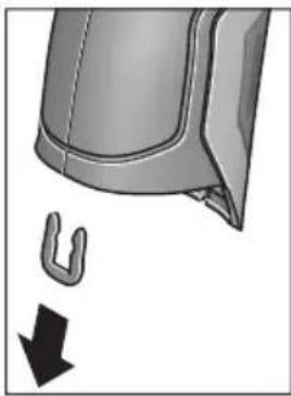
CypTe KepcetInReHEn Kopnyc Ka6bIKTapbIH YCTaHTbIH KaNCbIPMaHbI aNbIN KObHbI3. KopnyctaFb 6ypaHdaJapdbI 6ypan WbIFapbIN, Kopnyc KaNTaMaCbIH 3aybITbIK TaKaTaNwAmEH aNbIN KObIHbI3. KocankbI AkkyMnyTopDe (Tyme Xacyuacbl) Kopnyc iWlHde nataDa opHaJacKaH. Ohbl YCaFBWBbIHANbIFapBn KopaUFaHOpTaHbI KopFaNTbIH peTte KeJeE XapaTbIH3.
TexHKnabik 3e3epictepehri3y Kykbfb caKaTaNaDbI.
Româna
Instructiuni privind siguranta si protectia muncii

Henk Becker Helmut Heinzelmann Executive Vice President Head of Product Certification Engineering PT/ETM9

Robert Bosch GmbH, Power Tools Division 70764 Leinfelden-Echterdingen, GERMANY Leinfelden, 16.04.2015
Montare
Tel. service scule electrice: (021) 4057540
Fax: (021) 4057566
E-Mail: infoBSC@ro.bosch.com
Tel. consultancy@clienti: (021) 4057500
Fax: (021) 2331313
E-Mail: infoBSC@ro.bosch.com
www.bosch-romania.ro
Transport
Accumulatorii Li-Ionutilizati cad sub incidenta legislatiei cu privire la transportul marfurilor periculoase. Accumulatori pot fi transporta rutier de catre utiliser fara indeplinirea altero cerinte.
Henk Becker Helmut Heinzelmann
Executive Vice President Head of Product Certification
Engineering PT/ETM9

Robert Bosch GmbH, Power Tools Division 70764 Leinfelden-Echterdingen, GERMANY Leinfelden, 16.04.2015
Mоntиранe
3axpaHbAHe
H3mepBaTeHNHTypeN MoKe Da 6bIe 3axpaHbAH NnC o6NKHOBeHH 6aTePnn, NnC nITHeBO-NOHHa akMyIaTOpHa 6aTePnHa BOW.
KataNoxeh Homep 3601 K83 370: N3MepBaTeHnHrTypeD MoKe Da ce N3NoJ3Ba n Camo CbC cTaHapTHN batePHN.
Pa60Ta c 6bHKHOBeH 6aTePHN (IINCBA npn KaTALOKeH Homep 3 601 K83 370) (BHXTe CnR. A)
BaTePnIte ce noCTaBAT b aanTOp 3a 6aTePnI.
AanTopa 3a 6atepnn e npedha3naeH cmo 3a npedBndeHnte 3a ceTn a3mepeBaTeHH yepn Ha BoW n He Tpa6Ba da ce n3non3Ba c enektpoHHcTpymEn.
3a noctabhe Ha 6aTePnHe BkapaTc KyTnTa 27 Ha aantopapB rHe3dTo 3a akymyIaTOPHaTa 6aTepeN 29. BkapaTe batePnHe B KyTnTa Taka, KaKTo e NOKa3aHo Ha dHyppaTa Ha KaNaka 28. Pb3Hete KanaKa Hd KyTnTa, DOkato ycETte OTeTINBO npeuPaKbHe H KanakbT 3aTBOp NpIbTHO PbKOxBATKA tHa H3MePbATEHnYupei.
3a H3BaXdaHe Ha 6atePnnte HaTNChe Te 6nokpaunTe 6yToHn 3Ha KaNaka 28 n To H3BpnaTe. Pn TOBa BHmAbaTe 6atePnnte Da He H3NaHAT. 3a ceta Ta DpbKte H3MePbATEHnY ypeo 6bPnat C rHe3dOTo 3a AkymnatoHa 6atePnre 29 Harope. H3BaTe 6atePnnte. 3a Na H3BaInTe KytTnTa 27
OT rhe3doTo 3a akymynaTopha 6aTepeHra 29,3axBaHeTe KyTHaTa N C neKo npHTnCKaHcCTeHaT a HAcTpahn H3dbpNaIte OTH3MePbaTeHNHyapeJ.
BHa 3aMeHnTe BCnKn 6aTePn EndOBpeMeHHo. H3no3BaTe CaMo 6aTePn OT eHN n CbU npOn3BODnTeN i C eHaKbB KaNaTET.
Ako npoBnKHTenHO BpeMe HMa da n3non3BaTe ypeDa, n3BaXdaIte 6aTePHnte OT Hero. Ppi npoBnKHTenHO cbxpaHbAHe 6aTePHnte Moat da npotekat n da ce caMopa3peT.
Pa6ota c akymynaTopha 6aTePn8 (IINNCBa npn KaTANOKeH Homep 3 601 K83 370) (BHXTe fnr. B)
YnbTbaHe: N3noJ3BaHTo Ha HenoJXoJn 3a BaJn H3MePBAteIeH ypeJ aKymJatopHn 6aTePm MoKe da npedN3BnKa HepaBnHOT My fHKUOHHpaHe IIN NOBpeKdaHTo My.
YnbTbaHe: AkymlyaTophata 6aTeepnCe doctabu cactnuho 3apepeHa.3a da noCTnHte pInHata npOn3BOUHTenHOCT Ha akymlyaTophata 6aTeepn, npEn Da 3anouHeTe Ja rno3BaTe, r 3apepeTe DOKpaN.
H3non3BaIte cAmo nocoueHnte Bpa3deNa TexHueckn daHH 3apAHH yCTpoiCTBa.CaMoTe3n 3apAHH yCTpoi- CTBa Ca napaMeTpN, POnxOJaU 3a H3non3BaHaTa BB Ba7nI H3MepBaTeIeH ypeI NHTHeBO-IOHNa 6atePna.
ПиTNeBO-нOHHaTаakymyIaTOPha6aTePnЯMoKeJa 6bDe3apeKdHaNo BcRAKO Bpeme,6e3TOBaJa ce OToPA3raBaHaДbIroTaHIOCTTa.N.PpeKcbCaHe Ha 3apeXdaHeto He yBpeKdaakymyIaTOPHATA6aTePnЯ.
CneI aBTOMaTHUHOTn3KIIIOuBaHe Ha n3MepBaTeHNH ypeI He HATNCKaIte NOBuey NcKOBn IpeKbCBAu. AkymylaTopHaTa 6aTePn MoKe Ja 6bJe NoBpeHa.
3a noctabnHe Ha 3apeHeHaTa akymyIaTopHa 6aTepeH 30 a BkapaTe B rHe3DoTo 29,doKaTo C oTuYeTlNBo npeuPaKBaHe ce 3axBaHe 3dpaBO B pbkoXbTkATo Ha H3MePbATEeHHy uei.
3a nBaxdahe Ha akymylaTophata 6aTeprn 30 HATNCHeTe de6Iokupaunte 6yToHn 3 nI3dbpnaTe akymylaTophata 6aTeprn ot rHe3dOTo 29. PnTOBa He npnlaraTe cnna.
Pa60Ta c 06nKHOBeHN 6aTePHN (3 601 K83 370) (BHXTe fHr. C)
3a OTbaprHe Ha KaNaKa Ha rHe3dOTo 3a 6aTePnN 31 HATNCHe Te De6IoknPaunTe 6yToH N n3BaJeTe KaNaKa Ha rHe3dOTo 3a 6aTePnN.
PnnoocTabrHe Ha 6aTeepHte BHHMaBaTe 3a npabHaHaM NoIpaHocT, noka3aHa Ha KaNaka Ha rHe3doTo 3a 6aTeepHn.
IocTaBete OTHOBO KaNaka 31 I ro 3axBaHete C OTuETINBO npeUpaKaBAHe.
BnHaH 3aMeHnTe BCnKn 6aTePn eHNOBpeMeHHo. N3non3BaIte CaMo 6aTePn OT eHN H cbU pOn3BOuNTe n C eHNaKbB KaNaCtET.
Ako npoIbIxHKeTEnHO BpeMe HMaJa n3nO3BaTe ypeDa, n3BaXdaIte 6aTePHTe OT Hero. PpN npoIbIxHKeTEnHO cbXpaHЯBaHe 6aTePHTe MORa Da npoTeKaT Ja da ce camOpa3peJrT.
CBeTINHeH HnDnKaTOp 3a CTeNeHTa Ha 3apeDeHoCT Ha 6a- Tepnra
HnKaTopbTgHaIcnPnE Ioka3Ba CTeneHTa Ha 3apeDeHoCT Ha 6aTepeHnte, pecn. Ha akymyNaTOpHnte 6aTeepn 30.
| Сbvетонов | КаразитET |
| >2/3 | |
| ≤2/3 | |
| ≤1/3 | |
| ≤10 % | |
| Замене батерни, pecn. akymyatopни. 6aaterhi |
Pa6ota c ypeda
Pnyckahe B ekcnloaataua
IpeNa3BaTe H3MepBaTeHnHa yPeO TBnAra, DnpeKTHa CbHcEBA CBtHnHa, KaKTo N npax N 3aMbpCBAHHa.
He n3naraaTe H3MepBaTeHnHa ypeHa ekCTpeMHn TemnepaTyPhn Hn pe3Ku TemnepaTyPhn npomEHn. Ha- np. He ro octabTte IpoDbIgnteHIO BpeMe BAETOMoBn. Pn rOJIeMn TeMnpaTyPhn pa3NIkN OCTaBnTe H3MepBaTeHnAytpeD a Ce TEMpeHpa, ppeD a Ro BKIOUHTe. Pn ekCTpeMHn TemnepaTyPhn Hn rOJIeMn TemnpaTyPhn pa3NIkN TOHocTtHa H3MepBaTeHnHa ypeD MoKe Da ce BLOsH.
4aKaBaTe N3MepBaTeHnHrTypeIa Ce aKlHMaTH3npa do6pe. Pn rOleM TeMnepaTpHn pa3JIHKu BpeMeTo 3a akImMaTH3nPaHe MoKe Ja CTInrHe Do 15 min.
H36aRbAte CnHNyApn Hn H3nyCkAne Ha H3MePbaTeHNHa ype. Cnei CnHN BbHsHn Bb3JeCTBn H npn He npaBnHO fynKcHOnHpaHe Tp6Ba Da npedeAeTe H3MePBaTeHNyaPeD 3a npOBepKa B OToPi3npaH cepBn3 a eNekTPOHHCTpymEnHa BoW.
H3MepBaTeHNHTypee ccbOpBXeHc6e3XnueH HHTep-Feic.Tp6BaJa ce cna3BAt NOKaHNHe ORpaHNueHnB pexHMa Ha non3BaHe Ha 6e3XnUH yCTPOIcTBA,HaNP. BcamoIeTH HNN B60HNu.
BknIOuBaHe n3KnIOuBaHe
I3BaTeIpeJa3HaTaNapa21OTpHemaaTaJeua3a HΦpa-uePBeHn CngHann 23NpeJa3HaTaNapaKa 19 Ha ceH3opa 3a BnaXhoCT N TempePaTypa5.NoBpeMeHa pa6o-ta BHMaBaHTe Kamepata 22, pHemaaata Neua 23 n ceH3OpBT 5 Da He 6bDat 3aTBopeHHn NOKpHTn OT npE-MeTH, B IpOTHBEN Cnyauh H3MepBaHeTO Hma Da e BApHO.
3a BkIIOUBaHe Ha n3MepBaTeHnHa ypeH hATNCHeTe 6yToHa 12nn6byToHa 3a n3MepBaHe 4.HaDncPnEe 18 ce IoBBA HnHnHaHn3nPaAsTa NocLeNoBaTeHnOCT OT ekpaHn. Cnei HnHnHaHn3nPaUnTe ekpaHn H3MepBaTeHnT ypeD ce HAMpa B pexKmA, 3aJaMaTeH pnp NocJeHTo n3KJIIOUBaHe. Ja3epHTe BCE OSe He ca BkIIOUeHH.
Camo npn nyckaHe Ha ypeDa B EKcnNpoatauca n Cnei HnHuaHn 3npaHTe ekpaHn Ce NoBBA MeHIO To «YpeD», B KOEt MOKeTe Da HacTpOte NapaMeTpHa H3MepBaTeHnHaPeD, Ha- np. e3ka Ha BCnKu ekpaHn (3a o6cnykBaHe BVkTe «IOnMeHIO «YpeD»), CTpaHnCa 301). IOTbBpDeTe HacTpOknTe HaTNCHeTe JEBNa FyHKUHOHaJIe6byTOH 17. BCnKu HAcTpOKn MoRat Da 6bDat IpomeHHn I NO-KbCHO OTHOBO OT MEHIO «YpeD».
He octabnIte ypea BkHoueH 6e3 Hau3Op; cnei KaTo npKnIOHTe pa6Ota, ro n3KnOuBaTe. Ipyr nnca Mo- rata 6bdaT 3acnenHOn Tna3epnra NbU.
He hacoubaIte na3epnnaMbq KbM xopa nn JxHBOTn; He rIeJaTe cpeu na3epnnaMbq, CbUO n OT rONMO pa3ctoHne.
3a necteHa eheprrnB 3aBOda- npOn3BOHnte H aCtpoeho np6bn. 30 s cnei HaNTCKaHe Ha 6byToH rpkocTtHa dncnnpe da 6bDe HaamnaBaHa. Pn HAtnckaHe Ha npOn3BOJe 6byToh OCBeTneHHeTo Ha DnCnpe Ce ycInBa OTHOB. BMeHTo «PpOdbNkHTenHOCT Ha CBeteHe» MOKeTe Da IpOmeHITe ToBa BpeMe (BnXte «PpOdbNkHTenHOCT Ha CBeteHe», ctpanuca 301).
3a n3KIOUbaHe Ha n3MepBaTeHnHa ypeI HaTnCHe 6yToHa 3a BkIOUbaHe n3KIOUbaHe. n3MepBaTeHnHT ypeI 3aNaMeTBA TeKUzna pexHM Ha pa6Ota, KaKTO n pa3NnHHTe Ha-CTpOKn, n Ce n3KIOUbA. IocTaBeTe OTHOBo npedn3HaTa KaNaUka 21 Ha npneMaJtA Na 23 n npedn3HaTa KaNaUka 19 Ha ceH3Opa 3a BnaxHoCT n TempePaTypa 5.
He n3KIOUBaTe n3MePbATEHnYpeJ Upe3 n3BaXJaHe Ha aKyMylatOpHnTe/O6NKHOBeHnTe 6aTeepn, Tb Kato npn He- 6laOprnTHn CTueEHnHa o6CToTEnCTbTa BbTpewHata naMet MoKe da 6bJe NOBpeDeHa.
B MeHIOTo «BpeMe 3a n3KIOUbaHe» MoKeTe Da Na HAcTpoNTeДANI KOKO BpeMe CnED NocLeiHO HaTnCKaHe Ha 6yTOH n3-MepBaTeHNrYpeD Da ce n3KIOuH aBTOMaTHuHO (BHXTe «BpeMe 3a n3KIOUbaHe», CTpaHnua 301). CbIo N npH aBTOMaTHuHTo n3KIOUbaHe TeKUJIrT peXIMn I TeKUJIrTe Ha-CTPOIKN Ha ypeDa ce 3aNaMaTЯBaT.
Akoakymyataopnata6atepna,pecn.n3MepeBaTeHnIype ca H3BbH nocouehn B Texnueeckn daHHn TempepaTepn HTEpBaI 3a paOta, cIeN KpaTKOTpaHNO ppeynpeHnEO cb06uHne ypeDbT ce N3KJIIOUba ABtOMaTHUHO (BHXTe «PeuKN - npuHN 3a Bb3NKBAHe nHaUNH 3a OTcPaHraBaHETo HM, cTpaHnca 301).OCTabete N3MepBaTeHnIype Da ce TEMpePnpa Iro BKIIIOUte OTHOBcIeTOBa.
3a Da neCTHTe eHepnIy, BKNIOuBaIte N3MePBATeINHry ypeIcMo KOraTo rO n013BaTe.
HactpoBaHeHaCTeNeHTaHa yBemueHne
H3o6paKHeHTo Ha nucnIe npTekyUTo H3MePbAe H npBb3pOn3BExJaHTo Ha 3anaMeTeHn CHmKn Ha ekpaHa MoKe da 6bJe noka3BaHo c Tpr pa3nHu CteNeHn Ha yBeInueHne:0,5m,2m n 5m.
CTeneHHe Ha yBelenueHne ca ONTmN3npaHn 3a CbOTBeTHOTO pa3cToHHe MeKJy N3MepBaTeHNH ypei n o6eKtA: npn pa3cToHne 2 m CTeneHTa Ha yBelenueHne «2 m» daBa (o6NKHOBeHo) Hau-do6poto N3O6paKeHne Ha dinCnJe.
TekyuO n36paHOTo yBENUeHHe ce NOBRABa B NOIeTo e. 3a NOBnuaBaHe Ha CTeneHTa Ha yBENUeHHe HAITcHete 6yToHa-CTpeKHa Horope 16, 3a NoHNkaBaHe - 6yToHa-CTpeKHa HADOnly 13.
OcbetBaHe Ha H3MepBaHaTa IOBbpxHOCT
PnH3MepBaHe B TbMHN 30HN MoXeTe Da BKIOUHTe NaMnata 24,3a da IIOO6pIte H3O6paKeHHeTo Ha ekpaHa. ToBa MoXe da Bn NOMorHe da NoCTHrHete No-Do6bp pe3yntat npn 3ana3- BaHe Ha ekpaHHn CHHMKn.
3a BKNIOUBAHe, pecn. n3KNIIOUBAHe Ha IaMnata 24 HATNCHE6yToHa 14.
CζeI neCTeHe Ha eHeprHn IaMnTa Ce n3KJIIOUyBa aBTOMaTHuHo, KOraTo JRPoCTTa Ha nDCnPteCe HamaHb. B MeHIoTO «IpoDbJXHTenHOCT Ha CBeTeHe» MoKTe Da IpOMeHnTe BpeMeTo 3a CBeTeHe (BIXKTe «IpoDblNKeTIHOCT Ha CBeTeHe», CTpaHnCa 301). Pn IOBtOPHo BKlIOUBaHe Ha OCBtJeHneTo Ha ekpaHa IaMnTa He Ce BKNIOUyBa aBTOMaTHuHo.
Korato cbctoHHeTo Ha 6atePnnte E kptnHcHo, c orne ne-CTeHa eHepnna lamnata He MoKe da 6bJe BkIoueHa.
IodrotOBKaHaH3MepBaHeTo
HactpoBaeHa KoeΦnueHtA Ha n3bUbae 3a H3MepBaHe Ha NOBbpxHOCTHa TEMpepaTpa
3a onpeJenHe Ha temnepaTpyaHa NoBbpxHocTc He 3MmpBa 6e3KoHTA KTHO eCTeCTBeHOTo H3bYBaHe Ha HHpa-uepBeHHIbU O T Bn3npaHn OBekT. 3a npabInHO n3MepBaHepnpeH BCaKO H3MepBaHepTrpa6Ba De ce npOBepn EBEHTaJIH NO KopnHp a HAcTpoEHn Ha N3MepBaTeHNy ypeD KoEΦnEnHT Ha N3bYBaHe (BnXTe «KoeΦnEnHT Ha N3bYBaHe), cTaPAnuca 302).
3aДа npomeHHTe HAcTpoEHHa KOeФицeHT HaИЗльчBaHe,ИЗбepeTe «ГлавноMeHIO»(ВИЖТe «HaBUNpaHé B«「ГлавноMeHIO»》,Странцa 300).
- 3a HЯкон OT NaH-YeCTO CpeSaHITe MaTePnA Hi Ca Ha pa3- noloxHeHne IpeBapHTeHNo 3aIncAHN KoepuIeHTn Ha n3JIbUBaHe. B OIIuYra «MaTePnA» N36peTe NoDxOJa- uIy MaTePnA. CbOTBeTHnT My KoepuIeHT Ha n3JIbUBa- He e POKa3Ba Ha DoHnHa pei.
Ako Bn e N3BecTeH TouHna KoepuNHeH Ha N3NbUbaHe Ha oBeKaTa, KOTo H3MepBaTe, MoKTe Da BBBeTe UcCneHa Ta My CTOnHOCT B ONuHraTa «KoeepuNHeH Ha N3NbUbaHe»
HhOpMnpaTe ce 3a KoepnueHTa Ha n3bUbaHe Ha Baun MaTePnAn. Hapec cbc 3aIncanHe B n3MePbTeHNy ypeKoepnueHTHa n3bUbaHe, B Ta6nucata No-dony Ie HamepnTe KoepnueHTHa n3bUbaHe n 3a dpyrMaTePnAn.
He npbXTe H3MepBaTeHnHa ypeI He nOcpeCTBeHo Do ropeu NOBpXHOCTN. Bb3MOxHO e BCJIeDCTBHe Ha ha-rpBaHeTo da ce nobpeiN.
Ako Na3epHnTe TouKc Ce 3a6eJ3BaT TpydHo,HaIcnPnE MoKeTe Da BkIIOUHTe N3MepBaTeHApamKa b(BNKeTe «N3MepBaTeHApamKa),CTpaHua 301).N3MepBaTeHata pAmKa MOKe Da 6bJe NOJ3BaHa KaTo yKa3aTeI 3a N3MepBaHO ToH IO CnyxN 3a No-Do6po OpneHTnpaHe.
B 3aBncmocT O p3cToHHeTo H3MepeBaTeHaTa pAmka Mo-Ke da ce pa3nUaBA OT peaHNo H3MepeBaHoTo NeTHO. OnpeJeLJIo 3a H3MepeBaHeTo e pa3cToHHeTo MeKdY Ia3epHHTe TOuKn.
Yka3aHnna 3a OKoJIHnTe yCIOBn npn n3MePbAe
CnHNO OTPa3RBAuN HIN 6NeCTAUN NOBbpxHOCTN (HAnp. 6NeCTAUN PhaHCOBN NIOUKN HIN MetaHIN NOBbpxHOCTN) MoT a BNoWAT ToHOCTTa Ha H3MepBaHe Ha NOBbpxHOCTHaTa TEMepaTpa. Pn Heo6xOIMOC T3aNenTe Bbpy H3MepBaHaTaNOBbPXHOCT TbMHa MaTHpaHa JeHTa, KOrTo e Do6pe TonIOnpOBeKdAua. H3uKaaiTe KpatKO BpeMe JeHTa da ce TemNepnpa.
PnpeFNeKtpaunIOBbpxHocTH BnHmAbaTe da pa6oTne
noI NOxOJaBbN,3a Da He 6bDe BNOWeHa TOUHocTt Ha H3MepBaHeTo OT Otpaehn TOnnnnnn Nbyn OT dpyr n oBeKTn. Ha np. Pn H3MepBaHe OTnped nepneHdkyJrpHO OTPaxeHneto
Ha TOnnnHaTa OT BaWeto TAno MoKe Ja BNou H3MepBaHeTo.
H3MepBaHeTo ppe3 npo3paHn MaTepnaHn (HaNP. CtbKnlo
HIn PpO3paHn PnactMaCn) e HeBb3MOXHO No PpHcNl.
Pe3yntaHTe OT n3MepBaHeTo ca ToIkoBA nO-ToUHN IIO-Ha-
dEckHn, KOkOTO no-do6pn I NO-CTa6bUHN ca ycNoBnraTa,
pN KOnTO ce N3BbPwBA n3MepBaHeTo.
Ceh3opbT 3a BlaJxHocT Ha Bb3dyxa N OKoHaTa TempepaTypa 5 MoKe Da 6bDe NOBpeDeH OT XIMnueckn BeuecTBa, HAp. H3napeHnO rIakOBe Hn60n. H3MepBaHeTo Ha TempepaTypa qPe3 HnFpa-uepBeHn IbUc Ce BnRe O T HAnuHneTo Ha NyWeK, napa nOT 3anpaWeHocTt Ha Bb3dyxa.
3aToba npeiHn3MepBaHe B 3aTBopeHn NOMEuHn rN npoBeTpraBte,OCo6eHo aKO Bb3dUxbTe 3aMbpcEH nIN HMa MHOrO n3napeHn.
CneI npOBeTpBaHe n3uKaBbAte N3BeCTHO BpeMe n3paBnBaHe Ha TEMnepaTpynte B NOMEueHHeTo, Taka ye da 6bdaT IOCTnHaTHo 6nuaHHTe Hm CTOHOCTN.
OkoHaTa TemnepaTpa HOTHOCTeHa TaBnaKHOCT Ha Bb3DyXa CeH3MepBaTHeNOCpeCDBeHO OTyePa C NOMOHTa Ha CEH3Opa 5.3a NoCTnHaHe NaO6pn Pe3yIaTn He DpBXTe H3MepBaTeHNHpyed HENOCpeCDBeHO HAD NIN Do N3TOUHNi HaCMyueHnH, Hapr. OToPNIteHnTeHa NIN HEnOKpITn CbDOBeC TeuHOCT.B HNKaKBcnyaH He NOKpNBaTIe CEH3Opa 5.
PexmmHa n3MepBahe

Ochobeh ekpaH
a Data/aca: BnKTe «Ac/daTa», cTpaHua 301
b N3mepBaTeHa paMa: BnKTe «N3mepBaHo nTeHO npHn3- MePbaHe Ha NOBbpxHocTHa TeMnepaTpya», CTpaHnca 296
cEkapaHa cBcToHHneTo:

I3MepBaTeHnHTypee erTOB 3a I3MepBaHe, HATNCHETe 6yToHa 3a I3MepBaHe 4.

H3BbPbBaCe (HeIpeKbChaTo) H3MePBAHe, Na3epNTe Ca BKIOUeyH.

I3MepBaHTo e 3aBbPseHo, Ia3epnte ca I3KnHouEHn, pe3yIITaTHTe OT I3MepBaHTo Ca ONpeDeneHH.
d CnMBoN 3ByKOBa CNrHaJIH3aIINu H3KlIOUeHa (BnXTe «3ByKOB CNrHaJI), CTpaHnua 301)
e CnBbON 3a CTeH eHa yBENuHHe: BNXTe HAcTpoBaH e Ha CTeNEHTa Ha yBENuHHeNe,CTpaHua 295
f CnmboB Bluetooth® BKNIOUeH (BNXTE «Ппeнсян haДанHиЧe3Bluetooth®», CTpaHua 300)
g CnMBOI 3a CTeNEHTa Ha 3apeJeHocT Ha 6aTePnHa: BnXKe T «CBeTNIHeH INNkAToP 3a CTeNEHTa Ha 3apeJeHocT Ha 6aTePnTa》,CTpaHnca 294
h CnMBoN 3aФyHKuN/H3MepeHa CTOHOCHT HaOTHOCTENHaTBAJXHOCT
i CnMBoN 3aФункцИЯ/N3MepeHa cToHOCT Ha OKoJIHaTa TempepaTypa
j CnMBOI 3aФyHKU/ONpeJeHa CTOnHOCT Ha TOUkTaHa opocBaHe
mHIMMaHa/MaKcHMaHa H3MepeHa NOBbpxHocTHa TemnepaTypa npEHHuHO H3MepBaHe
CkaHa npe3yntaTHe
m CmB0JI "MeHIO"
n CnMBoI anapMa 3a noBbpxHocTHa TemnepaTpya: BnKTe «AnapMa 3a noBbpxHocTHa TemnepaTpya», cTpahNu ca 298
0 N3MepeHa cToHocHT Ha NoBbpxHOCTHaTa TempepaTypa
p TeKuypejHm
q MapknpoBka n3mepena cToHocT,pecn. pe3yIITaT (B3aBNCnMOCTOTn36paHHnpeKm)
rCmBOn3a ranepn
S CnMBoJ 3a yHKuJa/CpeJa cToHocT Ha n3MepeHaTa TempepaTypa
CnMBOJ 3aФyHKUH/N3MepeHa N0 KOHTaKTeH MeToD Tempeatypa
u Cnmbo3a KOeOuHnHa H3IbYBaHe
v CmboJ 3a namet
EHHHnHn H3MePbAHn
Upe3 eHOKpaTHo KpaTKOTpaHo HAHTCKaHe Ha 6yToHa N3-MepBaHe 4 Ce BkIIOuBaT Ia3ePHTe HcN3BbPbWA EHNHHUHO N3MepBaHe B N3bpaHnpeKHM. JpbXTe N3MepBaTeHnna yPeI HacOyen KbM N3MepBaHaTa NOBbPxHoc7 63 Da rO npMeCTBaTe, DOKaTO ce NOBn N3MepeHaTa CToHocT. PpouecbT Ha N3MepBaHe MoKe Da OTHeme Do 1 cekyHda.
Cnei npKIOUvaHe Ha 3MepBaHeTo Ia3epnte Ce 3KIOuBaT aBTOMaTHNO. Ha dncnpe Ce nOBBAbPe3yIITaHTe OT H3-MepBaHeTO.
HaTnCHete OTHOBo 6yToHa N3MepBaHe 4, 3a Ja CtapTpHpaTe HOBo N3MepBaHe C HaCTpoEHte NapaMeTpH.
HenpeKbchato n3MepBaHe
3a HenpeKbchato N3MepBaHe 3adpbXTe HaTCHa 6yToHa N3-MepBaHe 4. Na3epnTe octaBt BkNIOeHN.KaTO MeCTne ypeJa 6abHO, Hacooye IocIeIOBaTeHNO Ja3epHnTe TOnK KbM BCnKN IOBbPXHOCTH, YnATo TEMpepaTyPA nCKaTe Da N3MepHte. 3a N3MepBaHe Ha BIAJXHOCTTa N OKONHATA TEMpepaTyPA npemecTBaHTye pda 6abHO BnpocTpaHCTBOTO.
JaHHnTe HaIncnneJe Ce 06HOBaBt HenpeKbChaTo. Korato OTnyChHeTe 6byToHa H3MepBaHe 4, H3MepBaHeTo Ce npeKbCba, a Ia3epHe Ce 3KnIOuBAt. HaIncnneJe OCTaBat NocJeHNHe pe3yNTaTH OT H3MepBaHeTo.
HaTnCHete OTHOBo 6yToHa N3MepBaHe 4, 3a Ja CtaTpHpaTe HOBO N3MepBaHe C HAcTpoEHte NapaMeTpH.
3anametraBaHe/naKa3BaHe/H3npaHaHe Ha pe3yntaTH OT n3MepBaHTo
CneI npKIOUOBAHe Ha N3MepBaHe Ha DCNPIe Ce NOBBA CnMBoJIbT 3a NaMeT V, KOIT OPKa3Ba, Ye MOKeTe Da 3aNNuTe pe3yNTaHTe B NaMeTTa. 3a CEJI Ta HATNCHe 6byToHa 3anaMetraBe/H3npa7aHe 9.
Pe3yntaHTe OT n3MepBaHTo Ce 3aINCBat KaTO.JPG-paI (CHIMKaHa ekpHaC n3MepeHInTe cToHocTn).

-3a nokaBaHe Ha 3aHncaHn CHmKn HaTnCHeTe neBnaФyHKnOHaJIe H6yToH 17 noD cMBOIa 3a ranePra. Ha nCnIe Ce noBBAbNoCneHNO 3aNaMeTeHaTa CHmKa.
-HaTnCHTe 6yToHa-CTpeJIka HaIraCHO 11 nHn HnABo 15,3a Da npEInCTBaTe 3aNaMeTeHInTe CHIMKn.
-3a n3npaapane Ha Tekyuio NOKa3BaHnTe pe3yntaTn npes3Bluetooth® HATNCheTe 6byToHa 3anametraBe/H3npaane He. Ako Bluetooth® Bpb3kata OoIe He E BKIOUeHa (BnKTe «PpehaCHe Ha daHHN Upe3 Bluetooth®», CTpaHnca 300), Upe3 HATNCKaHTo Ha 6byToHa 3anametraBe/H3npaane Tc ce aKTHBnPa.

-3a n3TpBaHe Ha nOKa3aHnTe ekpaHHn cHmKn HATNCHeTe DecHn yHKuHOHaen 6yTOH 10 NOd CMBOJa "KoUe".

-3a da NOTBbPdnte n3TpNBaHeto,HaTNCHeTe neBn yHKuHOHaJeH 6yTOH 17 NOD CnMBOna «OTMeTKa».

-3a da npeKbcHeTe n3TpNaHTo,HaTnCHeTe DecHHaФyHKUHOHaJIe6bYToH 10 NOd CmBOI Na «X».

-3a da n3JIe3eTe OT pexnMa ralepnI Da ce BbpHeTe B pexnM n3MepBaHe,HaTnCHeTe neBnA yHKUHOHaIeH 6yToH 17 noI cIMBOJa «Ha3aI.
MoxTe CbI0 TaKa Da H3TpHe TBCnK 3aNaMeTeHn FaiNoBe HaBeIDhJk. 3a ZeIa BnXe «N3TpBaHe Ha BCnK n CHmKN》,CTpaHnca 301.
Pexmm n3MepBaHe Ha NOBbpxHocTha TemnepaTypa
BTo3npeKIMCeI3MepBaTempepaTpaTaHaIOBbpxHocTtHaI36paH o6ekt.
BTo3npeKIMMOKeTeHaNP.JaOTKpNBate NperPeTIN PpeNa-3HTeN INI Tpb6OpOBOn 3a TOIIA BODa, pecn. Ha OTONII-TeHb CnCTema.
3a CMHa B pexHm Ha n3MepBaHe Ha NOBpXHOCTHa TEmnepaTpy npH Heo6xOJIMoCT Ce BbPHeTe B OCHOBHnE ekpaH. 3a CEnta HATNCHEte HEKONKOKpAHO 6yToHa-CTpeJIka HAJIBO 15 HIN 6yToHa-CTpeJIka HADrCHO 11, DOKATO ce NOKaKe IPO3OpEuBT «NobpXHOCTHa TEmnpaTpy C KpaTko OBscheHne Ha pexHMa. 3a Da n3KNIOUHTe PPEKDeBpEMHo OBscheHneTo, HATNCHEte 6yToHa 3a ZanamETraBaHe 9. 3a Da n3KNIOUHTe OBscheHneTo n da CTapTtPaTe N3MepBaHe BeDHaRa, HATNCHeTe 6yToHa N3MepBaHe 4.
HaTnCHTe6byToHa N3MepBaHe 4 n HAcOeTe N3MepBaTeHnna ypeI nepneHnkyIaRHO KbM CpeIaTa Ha N3MepBaHnna oBeKT. CneI npNKIOuBaHe Ha N3MepBaHETo Ha B NOteo Ce n30-6pa3raBa NOBbPxHocTHaTa TemNepaTypa Ha NoCleDnna oBeKT, KbM KOITo e 6nI hAcOeH ypeIbT.
Pn npOdbJNKeIHH N3MepeBaHnIe Ce NOKa3Ba NocJeHNO H3MepeHaT NOBbpxHOCTHa TempeaTypa C MapKIpOBKaTa q HaCKaIATA 3a pe3yIaTAtI. MnHMaJIHATA MAKCMaJIHATA N3MepeHN Tempeatypn Ce NOKa3BaT B NOIeTo k, aKO pa3NIkata B N3MepeHIne CTOnHOCTn HAdXbBpNn 3 ^ C . Taka MoKeTe da BVINTE KbIe CE Hamnpa Tekyo N3MepeHaTc TOHOCr NO OTHOWeHne Ha Beue N3MepeHIne TEMpeatypn.
AnapMa 3a noBbpxHoctha temnepaTypa
AnapMaTa 3a nobbpxHocTha TemnepaTypa MoKe da 6bde n3- noJ3BaHa BbB BCnKu peXmN. MoKeTe Da HAcTpOnTe MHNMaHa N MaKcMaNHa TeMnepaTypa.
Ako TemnepaTpyata naHne noMHHMaHaTa TemnepaTypa, CmMBoJIbT aIapMa n Mna Cbc CnHr CBeTIHa H npN BkJIIOueHa 3ByKOBa CnHaN3aUncce CyBa npEynpeDnteHcNHaJ.
Ako TemnepaTpaTa HaXbPnMaKcMnHaTa TemnepaTypa, CmBOLt aIapMa n MIta C cepBeHa CBETInHa I npN BkUoyeHa 3ByKoBA CnHaIIH3aUNCe CyBa PpeynpEnTeHe CNrHaJI.
3a da non3BaTe yHKuYrTa AnapMa 3a noBbpxHocTha TempepaTpa, n36epeTe «FnaBHO MeHIO» (BnKTe «HaBnIpuHe B «FnaBHO MeHIO», CTpaHnua 300).
- N36epete noDMeHIO《ΦyHKUH》.
BkIIOUeTe AnapMa MmH/MaKc
B《AnapMaMnH》3aJaTe MHNMaHaTa TempepaTypa.
B《AnapMaMaKc》3aJaTe MaKcImaJIHaTa TeMnepaTpa.
BbBeHeHTe MmHmAlHa N MaKcHmAlHa TeMnepaTpyn Ce 3a- naa3BaT H CNeI KaTO NoCTaBHTe aIapMaTa B No3NcYA《H3KnHO- ueHo>.
Kohtaktho H3MepBaHe Ha TemnepaTypa
PnKoHTaKTHOtO H3MepBaHe Ha TEmnpaTpyc NOMOuTaHa cTaHapTHa TepMOBOnKa TIN K TEmnpaTpyaHa O6eKTo MoKe Da 6bJe H3MepeHa HENOCpeDCTBeHo.
YnbTbaHe: H3non3BaIte caMO TepMOeNeMeHTN OTTHN K. PnBKJIIOUBAHe Ha DpyTN BIDOBe TepMOeNeMeHTN e Bb3MOXHO rpeuHo N3MepBaHe Ha TemNepaTypaTa.
OTbOpTe KaNaUkKaTa 1 IN BKNIOueTe TepMOeIeMeHTa KbM KyNlnyHra 25.
- Ilpoyetete H cna3BaIte yka3aHnraTa 3a non3BaHe Ha TepmoeIemEHa.
Korato TepMOeMeMeHbT 6bDe BKNIOUeH, Ha IINcIIe Ce NOBBA CnMBoNt t. CTOHocTtA B NoneTo ce aKTyaIIN3npa HeIpeKbCHaTo. 3a Da 6bDe H3MepBaHeTo HaJeXdHNo, I3yakaiTe, DOKATO CTOHocTtA Cnpe Da ce H3MeHr. B 3aBNCIMoCT OT H3NbJIHeHHeTo Ha TepMOeMeMeHTa TOBa MoKe Da npOdbNxI Do HAKOLKO MNHyTN.
He3aBnCmO OT pexkma Ha pa6oTa KOHTaKTHaTatempepaTpa MoKe Da 6bDe H3MepeHa BdoTbHHeHne KbM NOBbpXHOCTHaT a TempepaTpa. 3a OnpedeJrHTo Ha TOnHHNMOcTOBe n OnachocTtA OT o6pa3yBaHe Ha PnceHn Obaue BnHa rCe B3Ma npedBn NOBbpXHOCTHaT a TempepaTpa.
Ako TepMoEneMeHTbT 6bIe H3KIIoueH, CImBOJIbT tHa DnCnnpe Ce cKpBa. CNeI H3KIIuOBAHeTo Ha TepMoEneMeHTa OTHOBO 3aTBOpTe KaNaUkata1.
PexHM OnpeDeneHa ToPnHHM MocToBe
B pexnma Onpedene Ha TOnHHH MocToBe ce H3MePbAt n CpaBnBaT NOBbpxHOCTHaTn OKoJIHaTa TempePaTypa. PnI TOnMa pa3Nka MeJy DBeTe H3MepeH N TeMpePaTypCe H3DaBa npedynpexdEHe 3a ToOnHHeMHOCCT (BHXTe «ToNNHeH MOCT》,CTpaHnca 302).
3a cMaHa B pexHm ToPnHHeM MoCT npn Heo6xOAnMoCT ce BbPHeTe B OCHOBnHa ekpaH. 3a ZeTnHa HATNCHeTe HeKoNkoKpaTHo 6yToHa-CTpeLka HaJIaBO 15 nH 6yToHa-CTpeLka HaJrCHo 11, DOKaTO Ce NOKaKe IpOzOpEcbT «ToPnHHeMocT C KpaTko 06rCheHne 3a peXmu. 3a da n3KlIOUHTe IpXdEBPemEHo 06rCheHneTO, HATNCHeTe 6yToHa 3a 3aNaMeTBAHe 9. 3a da n3KlIOUHTe 06rCheHneTO n da CTapTnpate N3MepBaHe BeDHaRa, HATNCHeTe 6yToHa N3MepBaHe 4.
HaTHNCHE6byToHa N3MepBaHe 4 HacOuye N3MepBaTeHnHa ypeI nepEnHykUyRHO KbM cpeIaHa N3MepBaHnObeKT. CneI npNKIOuBaHe Ha N3MepBaHTo B NOteO ce NOKa3Ba IOBbPxHocHTHa TeMnpaTypa Ha NocJeHNHa OBeKT, KbM KOto e 6Hn HacOuyen ypeDbT, a B NOteO i - OKONHaTa TempePaTypa.
I3MepBaTeHnHrTypeD CBePraBa CToHOCHTe aBTOMaTHUHO IPOka3Ba aHaHn3a Ha CToHOCHTe C MapKnpOBkata q Ha cKa- nata 3a pe3yntatn I:
- Mapknipobka q B 3eJIeHnI dIana3OH (pa3Ika B TeMnepaTpynte < 3,5^ ):MaIka pa3Ika B TemI epaTyprTe, HMa TOIIHHHMOCTOBe
- MapknpoBka q BkbltnnaHnana3OH (pa3nka B TemnepaTyPnTe 3,5°C do 6,5°C): tempepatpHa pa3nka B rpaHnHuata ObIaCT, Bb3MOxH0 e B 3OHaTa Ha n3MepBaHe da HMaToTnHHeMocT. Ha ToBa Macto n3Olaunrae Ta e MoKe 6n HeDIOCTaBua. NobTopeTe n3MepBaHe TOcE dN3BeCTe NepHOOT BpeMe. Pn ToBa BHmAbAte 3a BbHUnyCNOBn, KOITo MORAT Da NOBlnrT Ha pe3yntaTHe: DaII HAnp. n3MepBaHaTaNOBpxHOCT ce HarpRA BCNECTBne nonaDaHETo Ha npeKn CbHueBn IbuYn DAIu He Ce OXNaJda BCNECTBHe Ha 6n3OCTdo OTBopeHa Bpata.
- MapknpoBka q B uepBeHnДиana30n (pa3nka B Tempepatypnte >6,5^ ): NOBbpxHoCTHaTateMtnepatypaB rpaHnHTe Ha n3MepBaHOTo netHO ce OTnUaBA 3HaHTeHOTOKoJIHaTa Tempepatypa. B3OHaTa Ha n3MepBaHe HMaTOIINHEMOCT, KOeTo e yKa3aHHe 3a lo7a TOIINHHa I3OlaZnra.
Mожete Да Habtponte pbuHTo TempepaTypHaTа pa3nIka,OT KOЯTO MAPknpoBkata ce n3o6pa3raBa B uePbeHЯДиana3OH. 3a ZeNTa n3bepTe «Глвно MeHIO» (BnxTe «HabrHupaHe B «Глвно MeHIO»), cTaHnua 300). N3bepTe noDMeHIO «ФункцИ».В onUHTa «ToTnHHen MoCt» Habtponte JxenaHaTа TempepaTypHa pa3nIka.
PnHaJIuHneTo Ha TOIINHHMOCTOBe IPOBepTe TOIIHHaTa N3OJaCnB CbOTBeTHaTa 30Ha.
PexHM TemnepaTypa Ha opocBaHe
B pexnMa TemnepaTpaHa opocBaHe ce n3MepeBa OKoHaTa TemnepaTpaHa oTHocTeHnHa Ta BnaXHoCT Ha Bb3Dyxa (BnXte «OThcNtEnHa BnaXHoCT Ha Bb3Dyxa», cTpaHnca 302). OIbete cToHocThc ce onpeDenr TemnepaTpaTa Ha opocBaHe (BnXte «TemnpaTpaHa opocBaHe», cTpaHnca 302). Ocben ToBa ce n3MepBaHa NobbpxHocTha TEmnpaTpa.
TemnepaypataHa opocbahe ce cpaBnBa C n3MepeHaTa NOBbpxHOCTHa TemnepaTypa N pe3yntaTbT ce HHTepPepTnpa C orneonachocTta OT o6pa3yBaHe Ha nIeceHH.
Moi, 6bpeBHeTe BnMaHne, ye pe3yIaTHe CE OTHacrTa CMO 3a KOHKpeTHnte yCIOBnI NO BpeMe Ha I3MepBaHeTo, I3MepBaHe B npOdbJnxTeH e HTEpBaIOT BpeMe He e Bb3MOxHO. Ppi KpHTNuHn pe3yIaTn OT I3MepBaHeTo Tpr6Ba Da I3Bbp- Wnte CLeDaUH n I3MepBaHnB pa3NnH N MOMENTn I npi pa3NnH yCIOBnI.
3a CMHa B pexHM TeMnepaTypa Ha opocBaHe npH Heo6xoDmOCT CE BbPHeTe B OCHOBnE ekpaH. 3a cIeTa HATNCHeTe HEKONKOKpATHo 6byToHa-CTpeNk HAJrcho 11, DOKato Ce IOKaKe IPO3OpEcbT «Temnepatya Ha opocBaHe» C KpaTKO o6rCheHne 3a peXnMa. 3a Da n3KnIOHTe PpExDeBpeMeHHo 06rChEHneTO, HATNCHeTe 6byToHa 3a 3aNaMeTBAhe 9. 3a Da n3KnIOHTe O6rChEHneTO n Da CTapTnPaTe N3MepBaHe BeHara, HATNCHeTe 6byToHa N3-MepBaHe 4.
HaTnCHeTe 6yToHa N3MepBaHe 4N HAcOueTe N3MepBaTeHnHa yPeI nepIeHNkUyRPho KbM CpeIaTa Ha N3MepBaHnO6eKT. CneI npKIOuOBAHe Ha N3MepBaHeTO B NOIeTO O ce NOKa3Ba NOBpXHOCTHaTeMNEpaTypa Ha NocIeHNr O6eKT, KbM KOIT O e 6Hn HAcOeH ypeBt, B NOIeTO i - OKONHaTe MNEpaTypa, a B NOIeTO h - OTHCHTENHa TBAJxHOCT Ha BB3dYxa. N3UnCHeHATA TempePaTypa Ha opocBaHe ce NOKa3Ba B NOIeTo j.
H3mepBaTeHNHTypeCpaBHBa CTOHOCHTe aBTOMaTHUHO H NOKa3Ba aHaJIIN3a Ha CTOHOCHTe C MapKnIpOBkata q Ha cKaINaTa 3a pe3yUTaTI:
MapknpoBka q B3eHnnaHaOH: npn TeKyuInTe ycNoBn Hm aOnaCHOCT O6pa3yBaHe Ha npeHen.
MapknpoBka q B KbIITnAHa3OH: CToHOCHTe Ca B rpaHnHuHaT a OblaCT; BHIMaBaIte 3a TeMnePaTypata B NOMEuHeHNeTO, TOJIINHHMOCTOBe, KaKTo I BnaXHOCTTa Ha Bb3- dyXa H NOBTOpe TE N3MePBAHeTO B IO-KbCEH MOMENT.
MapknpoBka q B cepBeHnna3oH: cbIeCTbByBa nOBu-WeHa onaHocT OT obpa3yBaHe Ha IneceHH, Tb KaTo BNaXHOCTTa Ha Bb3dyxA e TBbpDe BnCOKa HnIOBbpxHOCTHaTa TempepaTypa e B dHa na3OHa Ha KOHdEHNpaHe. CbotBETHaTcTOHOCT MfA B NONETo CN.
N3daBa ce npedynpexkHe 3a o6pa3yBaHe Ha nIeCen, aKo NOBbpxHOCTHaTc TEmnepaTypa e 80% ot TemnepaTypa Ha opocBaHe. Pn onacnoct OT o6pa3yBaHe Ha nIeCen B 3aBNCIMOCOT OT npuHnTa Tp6Ba HnDa HamaHte BnaXHOCTTa Ha Bb3dUxHa Qpe3 No-VecTo NNo-HNTeH3NBHO pOBeTpRaHe, Hn Da yBvElnuHTe TemnepaTypaB NOMeueHneTo, Hn Da OTCTpaHInTe TOIIHHInTe MocTOBe.
YnbTbaHe:Cn3MepBaTeHnHa ypeI He MoKe Da 6bJe yctaHOBeHo HAIuHEnTo Ha CnpHa PteCen. ToI cAmO yKa3Ba, ye aKO yCTaHOBeHHTe npaMeTpnc Ce 3aNa3rT, cbIeCTByBa OnacHOcT OT o6pa3yBaHe Ha PteCen.
Iotppe6HTeJckn peKHM
B nOTpe6nTcKn peXm Ce n3MepBaT NOBbpxHocTHaTa n OKoHNHaTe Tempeatypn, KaKTo H BnaJxHocTTa Ha Bb3dyxa. OT Te3N CTOnHocTHCe ONpeJeTempeatypaHa OpOcBAhe, KaKTo H cpeHaTe Tempeatypa (cpeHa CToHOCHT Ha NOBbpxHocTHHe TEMpeatypn pnpnoDbnKInTeHNO n3MepBaHe).
Moxete Ha n3o6pa3nTe Ha ekpaa HcIeHNHe CTOnHOCTn: cpeHa TeMnepaTpya,OTHocHTeHa BnaXHoCT Ha Bb3dYxa, OKoHa TeMnpaTpya H TeMnpaTpya Ha opocBaHe.
3a ueTn36epeTe «IbnHO MeHO» (BnKTe «HaBnHpaHe B «IbnHO MeHO», cTpaHnca 300). N36epTe nOIMeHIO «ФункUnN» «Notpe6ntenckn peXmM. Tyk MoKeTe da BKJIQUHTe HIN N3KNIOUHTe NOpTeTa «CpeHa TemN.», «BnaJxHoCT Ha Bb3dYxa», «OkonHa TempePaTypa» «Temn. Ha opocBaHe».
Pn NOBbpxHocHTaTe TMnepaTypa MoXeTe Da H36epeTe daIIN MmHMmaHaTaN MaKcHMaHaTaN CTOnHocTn K Ha cKaIaTaN 3ape3yIaTn I ce onpeJeT aBTOMaTHUHO Nn Ce 3aDaBaT pHuHO. 3a CEJIa B MeHIOTo "NToPe6HtENckn PexHm" H36epeTeNoIMHeHIO To "Hana3OH Ha cKaIaTaN
- N36peTe «aBToMaTHuHo», aKo cToHocHTe k Tpr6Ba da ce onpeJeT aBToMaTHuHO, KaKTo e B pexHMa N3MepBaHe Ha NoBbpxHocTHa TemnepaTypa. MInHMaJIHaTa H MaKcHMaJIHaTA cToHocHT Ha TemnepaTypaTa OT TeKyUto N3-MepBaHe ce NOKa3BaT B NOIeTO k, aKO pa3NIkaTa Hm e noTOrJaMaOT 3°C.
- N36epete «Pb4H0», 3aДа BbBeTe cToHocTn. BbBeTe XeIaNHTe CToHOCTH B MeHIOTo «Iotpe6ntenckn peKIM» B NOJEtata «Ckana DonHa rpaHua» I «Ckana ropHa rpaHua». B NOJEtO K ce NOBRT BbBeHeHnte pBuHO MNHMaHa N MaKcMmHa cToHocTH.
Taka MojkeTe HaIp. Da HaNpaBHe CTHmKn Ha ekPaHa oT pa3JIuHn H3MepBaHncaBHMn Ha 6a3aTa Ha MapKnpoBkTa q.
3a CMHa B NTope6nteNCK npxHm pInn Heo6xoNMOcT ce BbPHeTe B OCHOBnHn EKpaH. 3a CEtNa HATNCHeTe HEKONKO KpaTHO 6yToHa-CTpeNkHaJIaBO 15 nnn 6yToHa-CTpeNkHaJaCHO 11,doKaTO ce nokAke npOzopeuBT «Notpe6nteckn peXHm C KpTaKo oBcHHeNe 3a peXHMa. 3a da n3KnIOUHTe npExDeBPemHo oBcHHeNeTo, HATNCHeTe 6yToHa 3a zanaMeTBAHe 9. 3a da n3KnIOUHTe oBcHHeNeTo n da CTapTnPaTe N3MepBaHe BeDnHa, HATNCHeTe 6yToHa N3MepBaHe 4.
HaTnCHeTe 6yToHa N3MepBaHe 4 n HacOueTe N3MepBaTeHnH ypeI nepEnDnKUpyrHO KbM cpeDaTa Ha N3MepBaHn O6ekt. CneI npNKlIOvBaHe Ha N3MepBaHeTO ce NOKa3BaT N36paHnTe CTOnHOCTN
PpehaheHa daHHN
IpeHoc Ha daHHupe3 USB nHTeppeca
OTbOpTe KanaaKaTa 1. CbbpKte MeNko-USB KynIyHra 26 Ha N3MepBaTeHnHa ypeD c BkIIOUeHnB OKOMIIeKToBkaTa Mnkpo-USB Ka6e8c Baunn KOMIOTpBp HnH HoYt6yK. 3aIncaHte JPG-faIIOBe MoRa Da ce KOINpaT, IpemecTBaHn H3TpNBat OT BrpaDeHata NaMeT Ha N3MepBaTeHnHa ypeD.. CneI KaTO n3KIOuHTe Mnkpo-USB Ka6ena, OTHOBo 3aTbOpTe KanaaKaTa 1.
YnbTaBe:Upe3 USB-INTepFeIca Cbbp3BaIte H3MepBaTeHnIypeI cAmO C KOMIObP HIN HOYbK. PpN BKNIOuBaHe KbM dpyrN yCTpoIcTBA H3MepBaTeHNrT ypeI MoKe da 6bJe NOBpeHn.
YnbTbaHe: AkymyNaTopHaTa 6aTePna Ha n3MepBaTeHnna ypei He MoKe Da 6bJe 3apeKdaHa npe3 USB-nHTepFeiCa. 3a 3apeKdaHe Ha akymaNaTopHaTa 6aTePna BHXTe «Pa6oTa c akymyNaTopHa 6aTePna», CTpaHnua 294.
IpehaeHa daHHuype3 Bluetooth
N3MepBaTeHnHTypee cBopbHexcBluetooth®MOyI, KOI TO N03BOJRABa 6e3XnueH npeHoc Ha DaHHN KbM ONpeJeEHN Mo6NJHN yCTpOiCtBa c Bluetooth® HHTepFeic (HaNP. cMapT-foHN, Ta6NeTH).
HhOpMaun3a Heo6xOdHMnTe CnCTeMHN H3NCKBaHn3a OcbIecTBBAHeTo Ha Bluetooth® Bpb3ka MoKeTe da HamepNe Ha HHTepHet cTpaHnUaTa Ha BoW Ha aDpec
www.bosch-professional.com.
3aДаВКИОчNTeBluetooth®иНТерфсЕнcaHaИЗМЕрВATEннуpeД,OTBOPeTe«「ЛавноMeHIO»(ВИЖTe«「HabINrHpaHeВ«「ЛавноMeHIO»》,CTpaHnua300)ипocтавETe«Bluetooth»ВПОЗИЯ«ВКЛ.,HaДИСПЯЕсnoRBAHaДПиcaf.YБерeteCe,ueBluetooth®иНТерфсЕнcaHaBaWEToMOБИнHo yCTpoi-CTBO CbIoo eakTNBEH.
3a pa3wipraBaHe ha cyHKUohHnO 6xBAt Ha Mo6uHnHOTO yCTPOICTBO n 3a yIeChraBaHe Ha o6pa60TKata Ha daHHnTe 4npMa BoW npEOCTABr CneuaHn npINOKeHn. B 3aBNCIOCT OT BnDa Ha MO6uHnTO yCTPOICTBO MOKeTe Da rN H3TeJIHTe OT cbOTBeTHnMaRa3NH 3a npINOKeHn (store):

Available on the
App Store

CneI cTApTnpaHTo Ha npInoKeHHeTo Ha Boi (Pnp aKTHBpuHan Bluetooth Moyn) ce n3rpaXda Bp3Ka MeJy Mo6nHOTO yCTPOIcTO H3MepBaTeHNH ypeJ. Ako 6bDat OT-KpHTN HAKONKO aKTHBHN H3MepBaTeHNH ypeJa, Tp8Ba Da H3-6peTe ypeJa, c KOtTO XeJAEte Da KOMyHNKpaTe. Ako 6bDeOTKpHT CaMo eINH N3MepBaTeHeH ypeJ, aBTOMaTHUHO ce n3-rgpaJda Bp3Ka C Hero.
YnbTbaHe: PnPbBTO n3rpaXdaHe Ha Bp3ka (Pairing) Mekdy n3MepBaTeHnry ypei N MO6uHNO ycTpoiCTBO (Hanp. cMaprfoH, Ta6JeT) e Bb3MOxHO da 6bDeTe 3aNHTaHn 3a PinKoI 3a n3MepBaTeHnry ypei. B TaKbB cnyuaih BBeDeTe «0000».
Pn npenoc Ha daHHu ype3 Bluetooth Moat Da Bb3HNKhat 3a6abHnB CnEcdTBe H a BNOsaBaHe Ha 6e3xNHaTa Bpb3Ka MeJy uCTpoiCTBOTo H3MepBaTeHHnYpeI.
《Главно MeHIO》
HabirhpaeB«TnaBHO MeHo

-3a da OTBOpHTe «TnabHO MeHIO», BOCHOHN eKpaH HaTNCHeTe DecHnI yHKUHOHaEN 6yTOH 10 NOc CmBOJa «MeHIO» m.
-3a HABINHpaHe B pAMKInTe Ha eIHO HNBO Ha MeHIOTaHaTnCKaTe 6yToHa-CTpeNka Harope 16,pecn.6yToHa-CTpeNka HAnOly 13,doKaTO JKeJIaHnEJeMeENT OT MeHOTo CTaHe UBeTeH.

-AKOBmTekyuO H6paHnHa eIeMeHT Ha NOpMeHIO,TOBa Ce O3HaUaBa C NOMoUTa Ha CTpeN Ka HADCHO DO «HAcTPOBbAte...》.3a Da BNe-3eTe B NOdMeHIOTo,HaTcHete 6yToHa-CTpeN Ka HADCHO11.

-AK03aH3bpaHnElenMeHTNMa H4KOJIko Bb3-MOxHH CTOHOCTH,OT KOHTo Da Ce H3bnpa,Te-KyuaTcTOHOCCTCe NOKa3Ba MeJdy DBeCTpeKN.3a Da IpomehHe T3bpaHata CTO-HoCT,HaTHcHete 6yToHa-CTpeKHa HAnBO15nn6yToHa-CTpeKHa HAdrCHO11.YncIeHNCTOHOCTNaOpBaTaDa Ce H3MeHrTNo-6bp3o,Korato 3aDpKHe HaTHcHAT CbOTBeTHn6yTOH.
- PnHAKOH eIeMeHTN OT MeHIO TO MOKeTe Da BKNIOHTE ININ N3KIOUHTE CbOTBeTHaTa FOHKcIa. 3a IN3KIOUBAHe HAITCHETe 6yTOHaCTpeIka HAIraBO 15, Taka Ye da 6bJe IN36paHO «N3KIOUeHO». 3a BKNIOBaHE HAITCHETe 6yToHa-CTpeIka HAIraCHO 11, Taka Ye da 6bJe IN36paHO «BKNIOUeHO». KOrato CTe B MeHIOTo, MOKeTe Da BKNIOUBAte IN3KIOUBAte FOHKUNrTa CbIo N Upe3 HATNCaHe Ha 6yToHa 3anaMetraBaHe/IN3npauahe 9.

-3a da ce BbPHeTe KbM NO-TopHO MeHIO,HaTHCHeTe IeBnI yHKUHOHaJIe H6yTOH 17 noCDNMBOla «Ha3aI.ИЗбpaHITe HAcTpoiKN Ce 3aNa3BaT.

-3a da HanycheTe «Главно MeHIO» Ида ce BbprHeTe HeNOCpeIcTBeHO B OCHOBnRA ekpaH, HATNCHETe DeChnAФункцioHaJIeH 6yToH 10 NOd CmMBOla «KbUa».ИЗранITE NaCTpoiKNCe 3ana3BaT.

-3a da HanycheTe npOn3BOJHO MeHIO Ja ce BbPHeTe KbM OCHOBHH eKpaH, MoKeTe Da HaTnCSHeTe CbIoo N 6byToHa N3MpBaHe 4. PnEHNOKpaTHo HAtNcKaHe Ha 6byToHa ce 3anaMeTBAt N36paHIne HaCTpOiKN, Ho BCE OUIe He ce CTapTnpa N3MpBaHe.
Поммен «Ураз»
OTBOpTe «IaBHO MeHIO» n36peTe NOnMeHIO «UpeN». To cbDbpka cneHNHTe enEmHTN:
-E3NK:
B MeHIOTo «E3NK» MOKeTe Da npOMeHrTe e3NKa Ha BCnKn ekpaHn.
- Yac/daTa:
3a npomHa Ha daTata u yaca Ha ekpaHa a n36peTe noMeHIO «Yacn Data». B TOBa nOdMeHIO MOKeTe cbIo Taka Da npomeHrte fOpMaTa Ha daTata u Yaca.
3a Hanyskahe Ha noDmeHIOTo 《Auc nData》HaTnCHTe HnI neBna cyHKUHOHaJIe 6byTOH 17 NOc CmBbOJa "OTMeTKa", 3a da 3aHHSeTe NaCTPOKInTe, INN DeCNH aYHKUHOHaJIe 6byTOH 10 NOc CmBbOJa «X», 3a Da OTXBpNIte HnPaBeHN- Te npOMeHI.
-Mepha eHnHua:
B MeHIOTo «EHNnHaMoKeTe Da n36peTe daIN daHHNTE 3a Tempepatpata Ce n306pa3raBbT B «O C» INN «OF»
- 3ByKOB cHrHaI:
B MeHIOTo 《3ByKOBn CnHann》MOKeTe Da BKNIOUHTe NIN N3KIOUHTe 3ByKOBJCnHaN, KOITo Ce I3JaBA npn aIapMaTa 3a NOBbPXHOCTHa TEMNEpaTypa.
-Измервашираамka:
BMeHIOTo《M3mepBaTeHa paMa》MOKeTe Da BkIouHTe HINN N3KIIouHTe N3MepBaTeHaTa paMa b Ha DCnner.
UBeTOba CXema:
B MeHIOTo UBeToBa CXema MoKeTe Da H36epeTe B KaKbB CBaT ce H3O6pa3raBt CToHocHTte 3a TempePaTy a DpyrIte IonoTa HaDnCnJe. HAcTpoNkata Ce BKnUoyBa n 3a 3aIINcaHHe ekpaHHn CHIMKn.
Bpeme 3a n3KnIOuBaHe:
BMeHIOTo «BpeMe 3a n3KIOUbaHe» MoKeTe da n36peTe INHTepBaIa ot BpeMe, cIeI KOItO n3MEpBaTeINHry UpeI ce n3KIOUba aBTOMaTHuHO, aKO He 6bJe hATnCHaT 6yTOH. MoKeTe CbIo Da IeAKTHBnPaTe aBTOMaTHuHO tN3KIOUbaHe, KaTO n36peTe OIzraTa «Hnkora». KoIKOTO No-KbCO BpeMe 3a n3KIOUbaHe HAcTpOnTe, TOLKOBA NOBeue eHeprna MoKeTe Da CnectHte.
IpoobnxHTenHcT Ha CBeTeHe:
B MeHIOTo «ПpoDbNKeTENHOCT Ha CBeteHe» MoKeTe Da n36peTe nHTepBaIa OT BpeMe, CnED KOITo RPKOCTTa Ha OCBeTneHHeTo Ha dncnEe Ce hAmalraBa, aKO He 6bDe HATnCHa 6byTOH Ha n3MepBaTeHNHa ypei. MoKeTe Da ocTaBtE OCBeTneHHeTo Ha dncnEe Da e BKIOueHo HEnpeKbChaTo, KaTO n36peTe OUNrTa «BnHar». KOnkOTO no-KbCo BpeMe 3a CBeteHe HactPOnTE, TOLKOBa IIOBeue eHeprMa MoKeTe Da cNcTHe.
H3tpBaHe Ha BCnKn CHmKn:
BMeHIOTo《N3tpnBaHeHaBCnKCHMKn》MOKeTe HaBeHNbKa Da N3TpneTe BCnKnΦaIIOBe, KOITc Ce HAMnPaT BbB BrpaIeHaTa NaMet. HatncheTe 6yToHa-CTpeNka HAnCHO 11 3a «Ose...》,3a Da BnE3eTe B NOdMeHIO.To BA HaTNCHeTe IINI NebNФyHKUHOHaEN 6yTOH 17 NOcMbOJa"OTMeTka", 3a Da N3TpneTe BCnKnΦaIIOBe, INN DeCNHnФyHKUHOHaEN 6yTOH 10 NOc CMBONA "X", 3a Da npeKbChTe DeIcTBNeTO.
- Hhopmaun3a ypega:
3a da BnDHTe HOpmaun 3a n3MepBaTeHnH ypei n36pepe Te HOpmaun 3a ypea). TaM MoKeTe Da HaMepnTe cepHHNHOmep Ha n3MepBaTeHnH ypei N BepCnTaHa IHCTaHnpAHcoftyep.
IpeuKN - npuHH 3a Bb3HKnBaHe H NaHH 3a OTcTaPaHBAHeTo NM
OTHOCHTeHa BnaKHOCT Ha Bb3dYxa
OTHOCHTeHaTbIaJxHOCT Ha Bb3dYxa NOKa3Ba KONKO TOnMa e HacHTeHoCTTa Ha Bb3dYxa C BoHN napn. CTOHocTTa ce npedaba KaTO pOoEHT OT MaKcImaHOTO KOINueCTBO BOHN napn, KOtO Bb3dYxbT MoKe Ja POeMe. MaKcImaHOTO KOINueCTBO BOHN napn 3aBNCN OT TempepaTypaTa: KONKOTO NOBVCoka e TempepaTypaTa, TOIKOBa NOBeue BOHN napn MoKe da POeMe Bb3dYxbT.
Ako OTHOCHTeHaTa BlaJXHOCT Ha Bb3dYxa e TBbpDe BncoKa, OnaCHocTtA OT o6pa3yBaHe Ha PIIeCEHc ce yBeHnUaBA. Tbbp- De HnCKa BlaJXHOCT Ha Bb3dYxa MoKe Ja npeHn3Bnka 3dpaBOCNoBn IpO6IeMn.
TemnepaotypaHaopocBahe
Tempepatypata Ha opocBaHe noka3Ba npK KaKaBb Tempepatypa HAMnPaUte ce BbB Bb3Dyxa BoHN napn 3aNoCbT Da KOHdEHNpAT. Tempepatypata Ha opocBaHe 3aBnCn OT OTHoCHTeHa T BlaxHoCT Ha Bb3Dyxa N OT Tempepatypata Ha Bb3Dyxa.
Ako TemnepaTypaHa Ha daheHa NOBbpxHocTe No-HNcKa OT TemnepaTypaHa opocBaHe, No Ta3n NobbpxHocT 3aNoUBa Da KOHDeH3npa B0da. KoHDeH3aunraTe TOKOBa No-CINHa, KOKOTO NO-TOJMAe pa3NIkata MeXdY DBeTe TEMnpaTypn H KOIKOTO NO-TOJMAe OTHOCHTENHa BAJxHOCT Ha Bb3dyxa.
OchOBHa npuHnHa 3a o6pa3yBaHe Ha nIeCen e KOHneH3npa- IaT a IO NBbpxHOCTTa Boda.
PoiDbpxKaHe n cepBn3
IopdbpxaHe n nouHCTBaHe
CbXpaHbAaTe N TpaHCnOpTnpaTe H3MepBaTeHNHa ypeD caMo B NOxOJaUu YaHTN/OnaKOBKn, HApN. OpHrHaHHaTa OnaKOBKa, pecn. IpePaNa3Ha YaHTa (He e BKIOueHa B OKOMJIeKTOBkata). HApN. He ro CbXpaHbAaTe B NlaCTMaCOB NIK, YHTo H3napEnH MoRt Da NobPeJrT CEH3Opa 3a BnaXHOCT Ha Bb3dYxa NOKoHa Tempepatya5. He 3aIeBaIte CTKePn Ha H3MepBaTeHNHa ypeD B6IN3OCT Do ceH3Opa.
He cbxpaHbAaTe N3MepBaTeHnHa ype npoBnKHTHo BpeMe N3BbH dHaNa3OHa Ha OTHoCHTeHnBa BnaXHOCT Ha Bb3Dyxa Mexdy 30 n 50%. Ako N3MepBaTeHnHrT ypeD ce cbxpaHBA pRn TBpDe BnaxHn Hn TBpDe cyxN ycNoBn, pRn BKIOUbaHE MoKe Da Ce CTnHrDo TpeKKn B N3MepBaHTo.
IopdbpkaTe H3MepeBATEHnYpeD BnHaTn UnCT.
I36bpcBaTe 3aMbpcBaHnTa C MeKa,NeKO HaBnaJHeHa Kbpna. He n3noJI3BaTe NOHCtBaU npenapaTH Wn pa3TBOpHTeTI.
Pn noHCTBaHe B n3MePbTeHnHa ypeI He Tp8Ba Da nonaDa BOda.
PouncBaIte N3KJIIOHTeIHO BHNMaTeIHO CneUHaIHO CEH3Opa 3a BnAIXHOCT Ha Bb3dYxa N OKONHa TEMpePaTypa 5, KaMe-pata 22, npHeMHaTa Ieua 23, lamNaTa 24 N I3XoJaIHTe OTBOPN 3a Na3epHIne IbUn 2:
BHMabaHTe no KaMepaT, npHemHaTaeIeIa IINn H3XoJaTIte OTBOPn 3a Na3epHIne IbUy da He octBaT BlnacNKn. NOpCTBaHTe KaMepaT, npHemHaTaeIeIa IIN3XoJaTIte OTBOp n 3a Na3epHIne IbUy c IppeIapATn, KOITc Ca IOnxOJaTIz 3a ObekTHBHTe Ha oToanapATn. He ce ONNTBaHTe Da OTCTpaHBAte 3aMbpCRABaHH C OCTpr PpeDMETn OT CEH30pa, KaMepaT aII IN pHemHaTaeIeIa, Ine TbPkAte C KbpNa KaMePATA n pHemHaTaeIeIa (OnacHOCTOT HApackBaHe).
PnHHeo6xOaMOCOT PEmOH NT3npaAsTe N3MepeBAtENHyaepBOpINHaJIHaTa ONAKOBKa INB PpeNtA3Ha YaHTa (He eBKJIIOUeHa B OKOMNKeTOKKaTa).
CepBn3 n TexHnueckn CbBETn
OTROBOPHnBaBbnpocHTeCNOTHOCHOpeMOHTaNIOpBxKkata Ha Baun npOdyKT MoXeTe Da NOnyUHTe OT HauuN cepBn3eH otDen. MoTAXHNueTpExn HnΦopMaun 3a pe3epBn YacTH MoXeTe Da HamePte CbIo Ha aDpec:
www.bosch-pt.com
Eknt ha Boa 3a texnueckn cbBETn npnoxehna ue otrobopn cyIOBOJCTBHe Ha Bbnpocnte Bn OTHOcH Ho hHTne npodyktn n DobnHHTenHtpe pncnoc6neHna 3a TAX.
Molny, npn npbukha Ha pe3epBHN uactH KOraTo HMaTe Bbnpocn BnHaHn NocOuBaTe 10-uzppeHna KaTANOKeH OmeP, n3ncaH Ha TaBeNkata Ha n3MePBAteHnY ypeI.
Po6epT BoW EOOD - BbIrapn
Bow CepBn3 LcHbP
TapaHNoHHn H3BbHrapaHNoHHn peMOHTn
6yn.YepnBpbx51-6
FPI Bn3HeC zentbP 1407
1907 Codpia
Ten.: (02) 9601061
Ten.: (02) 9601079
c (02) 9625302
www.bosch.bg
TpaHcnpTnpaHe
H3no3BaHInTe NHTHeBO-IOHHaKymyIaTOphN 6aTePnN Ca B O6XBata Ha H3NCKBaHNrTa Ha HopMaTHBnTE DOKymeHTN, Ka caeun IpoDyKTN C NOBNIeHa ONaCHOCT. AkymyIaTOphNte 6aTePnN MoT Da 6bDat TpaHCNoptnPaHn OT Notpe6bntenHa ny6bnHm MeCTa 6e3 DoNbHnTeHn Pa3peuHTenHn.
PnTpaHcnpOptnpaHe OTeTn CtpaHn (Hanp. npBb3dyweH TpaHCnopt Hnn NOn3BaHe Ha Kypnepeckn ycnyu) HMa cneunAJIHN 3NCKBAHnKbM ONaKOBaHETo N 06O3HaayBaHETo NM. 3a ceNTa PnPi NOrTOBkata Ha NaKeTpnaHETo Ce KOHCyItnpaIte ceknept B cbOTBeTHata 06nact.
N3npaansaeta kymyataopn6baetpnncam0ako Kopnycbt nM He e noBpeH. O6IeIeTe oKpHTN KOHTAeN ONAKOBAte akymaatopnata 6baetn TaKa, Ye Da He MoXe Da ce npemecBa B ONAKOBKaTa.
MOna, cnaBaIte n eBentyalHn DoNbHHTeHn HaCNoHaHn npedncaHn.
БракуВанe

C orneI ona3BaHe Ha OKoHaTa CpeHa N3MePbTeHn Hyaepi,OBHKHOBeHnte HnAkyMnaTOpHn 6aTePn,DObnHInTeHnTe PnHaJNeXHoCTN ONaKOBKnTe Tp8BaJa ce npedaBt 3a ONO3OTBopraBaHe Ha CbDbpKaunTe Ce TBx CypOBHH.
He n3xBpIyTe H3MepBaTeIHH ypeIu akyMyaTOpHn 6aTePnn/6aTePnn npn 6bntOBnTe OTnaDbu!
Cama 3a cTpaHn ot EC:
CbrnacHo Ebponeecka dInpeKTHBa 2012/19/EC n3MepBaTeHn ypeHn Cb- rnacho Ebponeecka dInpeKTHBa 2006/66/EO akymylaTopHN Hn o6NKHOBeHn batepHn, KOHTo He MoRat da ce HnON3BaT nobueye, Tpa5Ba Da ce cbHpata OTdElnHO nDa
6bDat noDlaRaHn Ha noXoJaHa npepa60Ka 3a onoN3OTBOpRABaHe Ha CbIbPkaUHTe Ce B Tx CypOBHH.
Akymynatopn Hnn 06nkHObeHH 6aTeepn:

Li-lon:
Mona, cnaBaTe yka3aHnTa B pa3- den «TpaHcnpTnpaHe», cTpaHnca 303.
IOnycka Ce demOHtnpaHeTo Ha BrgpaDeHnTe aKymyNaTOpHN 6aTepeHHcMoO T KBaJIHΦnUpaHH TeXnHcN C cen IprnpoDocb- 6pa3HOTo Hm N3XBbPnHe. Pn OTBapAne Ha Kopnyca n3- MePBATEHNHT ypeD MoKe da 6bJe IOBpeDeH.
3a da demoHTnpate nHTneBO- noHHata 6yfepeHa aKymnatoPHa 6aTePN, nbpBO n3BaTe aKymnatoPnHa 6aTePN 30, Pecn aanTepa 3a 6aTePN. DemoHTpae npePa3HOto CbKnO Ha dncnnr H cneT OBa KnaBnAtypata.
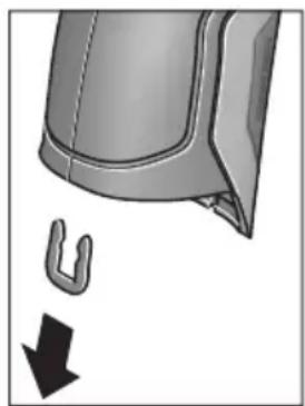
H3BaTe, KaKTo e NOKa3aHo Ha fHiYpata, U-CKo6ata, KOIto DbP Jx3aEHO UepynKIne Ha Kopny- ca.
Pa3BnTe BnHToBeTe Ha Kopnyca n H3BaTeTe UepyNkata Ha Kopnyca c Ta6eNkata.
ByepHaTa AkymytaTopha 6aTePnna (nnocka 6aTepeHna HaDbHHata nIaTKa B Kopnyca. H3TnackaHTe O THe3dOTo N I N3XbbpNeTe npnpoocbo6pa3Ho.
PpabaTa 3a H3MeHeHn 3ana3eHN.
MaKeDoHcKn
Бe36eДнОСН НАПОМЕН

CHTe ynatCTBa Tpe6a Da ce npouHtaaTn da ce BHIMaba Ha HNB, 3a Da MoKe 6e36eHNO 6e3 onaCHOCT Da pa6oHTte Co OBOJ Mepen ypei. DOKONky MEPHOT ypei He ce KOpNCTH corNaCHO npHIOKeHNTe
HNCtpyKcH,MOKe Da ce HapuyhФyHKcJaTaHa BrgpaTeHHe 3aUHTTHm MexaHn3Mn BO MePHNOT ypeI. He ja OwTeTyBajTe 03Ha KaTa 3a NpeDynpeDyBaBe Ha MEPHNot ypeI.DOBPO UYBAJTE IN OBNE YIATCTBA IN PPEADETE IN 3AEHDO CO MEPHNOT ypeI.
BHHMaHHe - JOKONky KOpHCTHTe dpyrN ypeHn 3a noDecyBaBe H paKyBaBe OCBEN OBDe HaBeJeHNTe HIN nonHaKBN NOCTANKN, OBA MOKe Da IOBeE Do ONaCHA n3IOXKeHcT Ha 3paueHe.
MepHnot ypeI ce hcnopauyBa co hatnnc 3a npedynpeDyBaBe (03hauHcHa npHKa3OT Ha MEPHnot ypeI ha rpaΦnKata cTpHa co 6poj 7).
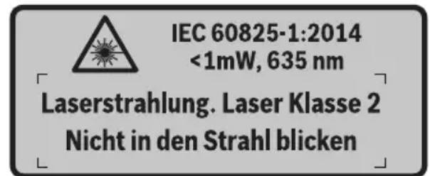
DOKONKY TEKCTOT Ha HanelHHuata 3a npedynpeyBahe He e Ha BauHOT ja3NK, Bp3 Hero 3aneneTe ja HanelHHuata Ha BauHOT ja3NK nped npbata ynotpe6a.

He ro hacouybaje nacepcknot 3paK ha IHHa HnH JnB0THN He norneHybajte dIpeKTHO BO HERO HnH HeroBaTa peFNeKcju. TaKa MoKeJa Tn 3acJeNITe IHHaT, Da InpEni3BnKaTe HecpeKn HnDa rH OwTeHTe OuyTe.
Iokonky nacepcknot 3paK docnee do ouHTe, Behdaw Tpe6a da rH 3aTbOpnte H da ja TprHete rnaBata od nacepcknot 3paK.
He BpweTe HnKaBn IpomEnHa NaacepckNoT ypeI.
He rH KopnCTe nacepcknte ouhna kako 3aWHTTHn ouhna. Nacepcknte ouhna cnykaT 3a noo6po npeno3HaBaHe Ha nacepcknoT 3paK, Ho He 3aWHTTyBaAT od nacepckTO 3paueHe.
He rKopncTe nacepckte Ounna KaKO OUnna 3a coNue HnN NAK BO COOpaKaJOT. Nacepckte OUnna He daBaat cEnoCha UV-3aHTnTa n Ro HaMaNyBaat npeno3HaBaHBeTo Ha 60n.
MepHnot ypeD cmee da ce nonpaba cAmo od cTpaHa Ha KBaHHΦHKyBaH CTpyeH nepcoHAn co OPHnHaHN pe3epBHN DeNoBn. CaMo HA ToJ HauNH Ke 6uTe CnHyprN BO 6e36eHnoCTa Ha MEPHnot ypeD.
He ng octabajte deuata da ro kopnctat nacepcknot Mepen ype63 na30p. Moke da ng 3acnenat npynte Niua nopadi HeBHMaHne.
HeepotetecoMepHNOTypeBBOOKOJIINHKAade NOCTOn onaCHOCTODEKCNI03Ha,KadeHMA3aapanHB TeuHOCTn,racHnnpaunHa.MepHOTypeDco3daBa NCKPN,KOIMoKe Da ja 3anaanat npabTaHnnapeata.
He ro hacouybajTe 3paKOT cBETnHa ha INaHa Hnn KHBOTHn H He NorIeHyBaJTe dIpeKTHo BO Hero, dypn HN OJ rONema oDdaneueHoCT.
Ppe6nlo KaKbA HInTeBHeuJa Ha MePnOt ypeI (Ha np. MoTaxa, OdpXyBaIbe nTH.) KaKo H npH erOB TpaHcnpT H OdpXyBaIbe H3BaIeTe rN 6aTepeHnte oMepHnOt ypeI. Ppr HeBHmAteJIHO paKyBaIe co npeKNHyBaOT 3a BkLyuyBaIbe/HckLyuyBaIbe NoCTOn ONaCHOCT OI NobpeHn.
He ja otbopajre 6aTepujara. NocToH onaCHOCT OJ KpaTOK cNoj.

3aHTtete ja 6atepnjata od TOnnHa, Ha np. OdoTpaJHO nIIOxUbaBe Ha coHcEbn 3paun, oran, BODa H BNara. NaKy, NocToH ONaCHOCT O ekCnlo3nja.
HeynoTpe6eHa7 6aTePnJa dpKte ja noJaIeKy od KaHcIepnckn cNojyBaNkn, KnyueBn, JKeIe3Hn napn, KInHcN, WpaΦOBn Hn Dpyr n Mann MetaHn npedMeTH, wTo MoKe Da NpeDn3BnKaat NpeMoCTyBaHe Ha KOHTaKTHTe. KpaTOK cNoJ meFy KOHTaKTHTe Ha 6aTepnjata MoKe Da NpeDn3BnKa n3ropeHnCn Hn NoXap.
Pn norpesho KopncTehe, Moxe da ncteue Teuhocta od 6aepnjata. N36erhybajte KOHTaKT co hea. JOKONky cnyajno dojdeTe BO KOHTaKT CO TeUHOCTa HCnnaKhete ja co BODa. JOKONky TeuHOCTa Dojde BO KOHTaKT Co ouHTE, no6apajte nekapcKa nomow. HCTeehata TeuHOCT oN 6aepnjata Moxe da npedn3Bnka KoxHH npHTaun nn H3ropeHNs.
Dokonky ce owtetn 6aTeepjata nH He ce Kopnctn npabuHno, od Hea MoKe da H3ne3e Napea. Bhece CBex BO3dyx N DOkONky HMa NOBpeHn Ondecete rHa nekap. Papeata MoKe da Hn Hndpa3Hn DNshHnte naTnTa.
Batepnite nonheTe rH co nonhaun uTo ce npenopaahn HCKnyuHBO oD npOH3BOUHTeNoT.
Iokonky nonhaot koj e npnafoen Ha eeden cooDBeTeH BnD 6aepnn, ro Kopncntte co npyn 6aepnn, nocton onachoct od nokap.
KopnCTe6aTePNKoCecooBETHaBaHOT npOn3BOO od Bosch.CamHOToJNaHHbATEpNJataKe ce 3aHTTN OI ONaCHO ppeONTOBAPyBaHe.
KopncTe cAmO opHnHaHb Bosch 6aTePm co HanoH KOj e HaBeDen Ha CneuHkaunohata nNoUka Ha Baunot Mepen Upe. Pn KOpncTeHe Na Dpyr 6aTePm, Ha np. mHTaun, nCTpoWeHn 6aTePm nHn HeNo3HaTH npOn3BODIne, NoCTOn OAnchocT od NOBpeN KaKO mATEpNJAHn 7TeTn DOKOLky EcKnloDnpa 6aTePnjata.
Batepnjata Moke da ce owtetn od octpnte npedmetn KaKO Ha np. Knnncn Hnn ODBpyBauchn HnabOpeuho Bnjanhe. Moke da doje de BHaTpeuhen KpaToK cnoj n 6atepnjata Moke da ce 3anaH, nuTn qad, ekCnIoNpa nn da ce pperpee.
BHHMaHHe!PnKopHCTeBeToHaMepHNOTypeCo BluetoothMOKeJaHactaHATnpeuKNHaDpyrHte ypeHnCnCTeMH,ABHOHNMeHnHCKnAnapatn(Ha np.nejcmejkep,anapatunba3aCnyuhae).NcToTaKa He MOKe cOecMa Da ce HCKnyuAT WTeTHNe BnJahnHa HaNyfeTOHXNBOTHnte BO HeNocepEnHaTo OKoINHa.He ro KopHCTeMePNOTypeCoBluetoothBO6n3nHa Ha MeHnCHKnYpeHn,6EH3NHCKn Nymnn,Xemnckn ypeHn,OBnactnCO onaCHOCToEKCnIO3nHa BO 6n3nHa HA MmHcKn nOnnBa.He Ro KopHCTeMePmHOT ypeCoBluetoothBO ABHOHN.N36erHybajTe DonIroTpajHa YnoTpe6a Bo DnpeKTHa 6n3nHa Ha TeNOto.
O3HaKaTa co 36OpOBu Bluetooth® kako n cInKnTe (noroata) ce perHcTpnpaHH TPROBcN MapKn n conCTBeHocT ha Bluetooth SIG, Inc. Cekoe KopncTeB e Ha OBaa O3HaKa co 36OpOBu/cInKn Ce Bpshn Co IInCeHua npeky Robert Bosch GmbH.
OncnHa npOn3B0DoT mOkHocTa
Be monime otBopete ja npekloneHaTcTpaHnca co npHKa3 Ha MepHnot ype, n dpKte ja otBopena dOeKa ro uHTaTe ynatCTBOTO 3a ynotpe6a.
YnOtnpe6a co COoDBeTHa HameHa
MepHnOT ypeE haMeHeT 3a 6eCKoHTaKTHO MepeHe Ha NOBpHHcKa TemnepaTpya, am6neHTaJIHa TemnepaTpya n peLaTINbHa BnaJxHOCT Ha BO3dYxOT. Toj jaIpcmEtYBa TOUkata Ha poceHe H yKaJyBa Ha TOnIIHcKInTe MoCtOBn I OnaCHOCTa OD NoJaBa Ha MyBna. Co MepHnOt ypeI He MoKe Ja ce DeTEKTnPaAT Cnpn Ha MyBna. MerTyoa MoKe Ja NOMorHe HABPeme Da Ce OTKpnJat YcNobITE BO KOn MoKe Ja ce CO3daDat Cnpn Ha MyBna.
MepHnOT ypeI He cMee Ja Ce KOpNCTn 3a MepHe Ha TemnepaTpata Kaj Nua JKNBOTHn NIn 3a DpyrmeDnHcNtCn CEJI.
MepHnotypeHe e nOroeH 3a MepeBeHa TeMnepaTyprn Ha racOBn.MepeBetoHa TempePaTypaHaTeuHOCTn E BO3MOXHO NCKlyuNBO CO NOMoH Ha oBueH TepMoEneMeHT (TNn Ha npNKlyouK K), KOJ MOKe Da ce npNKlyuN ppeky npEdnHeHNot HHTeppejc 25 Ha MEPHnotypeI.
CBeTnTo Ha OBOJ Mepen UpeE HamaHeTo 3a OCBeTnyBaHbE Ha DnpeKTHoTo paBtHO None Ha MepHnOT ypeI 3a peHCTpHaBHe Ha CnKNITE. Toa He e HamaHeTo 3a OCBeTnyBaHbe Ha IPOCTOpHInTe BO DOMaKnHCTBOTO.
Iacepckite ToCKn He CMeat Da ce KopncT aKao Iacepckn noka3aTei. Tne cnjkat NcKluyuNBO 3a O3NaUyBaHe Ha MePhata NOBpShHa.
Hnyctpaunja Ha KOMnoHeHTN
HymepnpaheTo Ha cInKHTe CO KOMHOHeHTN Ce OndecyBa Ha npka3OT Ha MEPHtE anapatn Ha rpaqNkata CTpaHnca.
1 POKlone3a Mnkpo-USB-OTBop/npnKnyok 3a Tepmoelement (TIN K)
2 N3ne3eH OTBOP 3a IacepcknOT 3paK
3 Konue 3a otKnyuBaHe Ha akymyIaTOp/6aTePncKn aanTep/nokloneu Ha nperepaDATA 3a 6aTePn
4 Konue Mepebe/koune 3a BknyuBahe
5 Cen3op 3a BnaXHOCT Ha BO3dyXOT N OKoHnHaTeMnepaTpya
6 Cepnckn 6poj
7 Hatnnc 3a npedynpeyBahe Ha nacepot
8 MmKpO-USB-Ka6eN
9 Konue 3auyBaj/ncpataH npeky Bluetooth®
10ФункцнсКОпчеДecHO
11 Konue co ctpenka decho
12 Konue 3a BknyuBaHbe-NCkyuBaHe
13 Konue co cTepeKa HApOly/HaMaIyBaBe Ha CTeneHOT Ha 3ymipahe
14 CBeTna 3a KOnpeTo 3a BKnIyUBaHbe-NCKnIyUBaHbe
15 Konue co ctpenka neBO
16 Konue co cTpeKa Harope/3roJeMyBaHe Ha cTeNeHOT ha 3ymipahe
17ФункцнскКончелев
18 EkpaH
19 3aHTTHo KaNaue 3a CeH3OpOT 3a BnaXHOCT BO Bo3dYxOT N OKOIHaTa TemNepaTypa
20Држаузврькata
21 3aHTnTHo Kaane 3a npneMHata Jeka 3a INHpaPBeHa CBETNIHa
22 Kamepa
23 PnemHa neka 3a HnPpaucpBeNo 3pauehe
24 Cbetna
25 Tn-K- npnknyok 3a TepeMoenemehOT
26 Mnkpo-USB-npknkyok
27 06BnBka 3a 6aTePnCKnT aanTep
28 Kanaye 3a 3aTBopaHe Ha 6aTepeNCKnO aanTep
29 Pperpa 3a 6atepnjata
30БатериJA*
31 Tokloneu Ha npperpaata 3a 6aTepujata
*OnnhaHata onpema npkackaHa Ha cInKHTe He e den oCtAndapHHOT o6em Ha Hcnpoka.
Texnuchn noaToCu
| Термode tektorp | GIS 1000 C | GIS 1000 C |
| Бpoj на dean/артын | 3601 K83 3.. 3601 K83 370 | |
| РавOTNO пõе | 0,1-5M 0,1-5M | |
| Мерно пõе | ||
| - Tempepatура на површина | -40...+1000 °C | -40...+1000 °C |
| - Контхда Tempepatура | -40...+1000 °C | -40...+1000 °C |
| - Окална Tempepatура | -10...+50 °C | -10...+50 °C |
| - релатвна влажноct на bo的事情 | 0...100% | 0...100% |
| Точность по мераfterо (тимпуна) | ||
| Tempepatура на поьш. 1) 2) | ||
| -40...-20,1 °C | ±2,5°C | ±2,5°C |
| -20...-0,1 °C | ±1,5°C | ±1,5°C |
| 0...+100 °C | ±1°C | ±1°C |
| >+100 °C | ±1% (>400 °C=±2%) | ±1% (>400 °C=±2%) |
| Окална Tempepatура | ||
| Тимпуно | ±1°C | ±1°C |
| релат. влажи. на bo的事情. 2) | ||
| <20% | ±3% | ±3% |
| 20...60% | ±2% | ±2% |
| 60...90% | ±3% | ±3% |
| Оп Tina (соordentlich сиземецю pactоjasни:Мерна точа) 3) 4) | 50:1 50:1 | |
| Класа на паср | 2 | 2 |
| Тини на паср (тимпунe) | 635 nm, <1 mW | 635 nm, <1 mW |
| Диjsamетар на ласрскп зразak (при 25 °C) okoly | ||
| - В 1 м расто щанne | 6 MM | 6 MM |
| - В 5 м расто щанne | 10 MM | 10 MM |
| Бaterи (алкални манганскп) | 4x1,5VLR6(AA)(co baterискп щадпэр) | 4x1,5VLR6(AA) |
| БaterиJA li'thym-johcka) | 10,8V | - |
| Вremетраеве на пабота | ||
| - Бaterи (алкални манганскп) | 3u | 3u |
| - БaterиJA li'thym-johcka) | 5u | - |
| Бpoj на сдени BO ватрешина Тмориа на сдени (тимпунe) | >200 | >200 |
| Bluetooth® | Bluetooth® 4.0(Bоobичаени и Ниска egerгina) 5) | Bluetooth® 4.0(воobичаени и Ниска egerгina) 5) |
| USB-nрклунок | 2.0(1.1-kompanьлени) | 2.0(1.1-kompanьлени) |
| Текина согласно EPTA-Procedure 01/2003 | 0,55 кг | 0,55 кг |
| Димензий (Должina x ШирINA x Висна) | 136x89x214MM | 136x89x214MM |
| Дозвole納а Tempepatура на okолинаtra | ||
| - ри палные | 0...+45 °C | - |
| - ри пожес на paбotinga 6) | -10...+50 °C | -10...+50 °C |
| - ри скадралье | -20...+70 °C | -20...+70 °C |
| Пробачани baterи | GBA 10,8V ... | - |
| Пробачани палачи | AL 11..CV | - |
1) npn0,80 m n3mepeno pactojaHne od noBpHHata
2) npn okolna temepaIpya od 20-23°C n cTepeHa emncja>0,999
3)Падатουи BO corlaachocet co VDI/VDE 3511 nct 4.3 (darym Ha objaba jyln 2005); baxn 3a 90% od Мернот сгтан.
Bo cHTe noDpaJa, hAnBOp od npKakxAHnte roIemHn BO TexHnKu NOaTOU, MOKe da JoJe DO OTCTaYBaHa Ha MEPHHe pe3yTATM.
4) ce odncyba Ha nHpauzpeHo Mephe, noIeHHeTo rpaHnKnot npka3:

5) Kaj Bluetooth®-ypeinte co Hscka eHepnja, BO 3aBnCHoCT OJ MOeIOT N OpeaTHBnHT CnCTeM He E BO3MOKHO BOCnOCTaByBaHe Ha BpCKaTa. Bluetooth®-ypeinte mopa da noDprkyaar SPP npoФи.
6) orpahnueha jaunha npntempeparpyn < 0^
Texnukte npatoun ce ha ncpopauhata 6atepna.
Cepnckno6poj 6 na cneunu Kaunohata nnoyka cnyykna ha ja cna ndhknkaunja Ha Baunot Mepe np
N3jaba 3a c0o6pa3HocT C
TbpHMe Ha HaHa oJROBOpHocT, DeKa npOn3BOoT OnHuaH BO,TexHNuKN POnaToOn "OJROBaPa Ha CHTe COODBeTHN OJpe6bOndInpEeKTHBnTe 2009/125/EC (npOnnc 1194/2012),1999/5/EC,2011/65/EU BknyuHTeHNO HNBnTe IpOMeH e Bo CoIaChOC T cJeDnHe HOPM: EN 61010-1:2010-10,EN 60825-1:2014-08, EN 300 328V1.8.1:2012-06, EN 301 489-1 V1.8.1:2008-04, EN 301 489-1 V1.9.2:2011-09, EN 301 489-17 V2.2.1:2012-09, EN 62479:2010-09.
Texnuka Dokumenteuja kaj: Robert Bosch GmbH, PT/ETM9, 70764 Leinfelden-Echterdingen, GERMANY
Henk Becker Helmut Heinzelmann Executive Vice President Head of Product Certification Engineering PT/ETM9

Robert Bosch GmbH, Power Tools Division 70764 Leinfelden-Echterdingen, GERMANY Leinfelden, 16.04.2015
MONTAXA
HanojyBahe co eheprnja
MepHnot ypeD moKe da ce kOpHCTn nn co o6uHN 6aTePNnn Co JNTnM-jOHCKn 6aTePNn od Bosch.
Bpoj Ha den/apTkn 3601 K83 370: MepHnoT ypeD moKe da ce ynoTpe6yBa ncknyuNo co o6nUn hbaTeprnn.
OcbetnyBaBe Ha MepHaT a NobpwnHa
Pn MepeBe BO TEMH NIOpaJa MoXeTe Da Tn BknyuHc TeBETNaT24,3a Da IIOO6pIe PnKa3OT Ha CoDPxNHaTaHa ekpaHot. OBa MoXe Da Bn NOMorHe Da NoCTnHrTe NDo6ap pe3yNTat Pn 3auByBaHbe Ha KaDn OD ekpaHot.
3a BkIyUyBaHbe Ond. NckIyUyBaHbe Ha CBETnata 24 npITNCHeTe Ha KO nueTo 14.
CBeTnataKe ce n3racat aBtOMaTcKn 3apaN 3aWteJa Ha eHepnja,doKoIky ceHaMaJI naJauHATA HaOCBeTnyBaHbeto Ha ekpaHOT.Bo MeHInTo „BpeMeTp.Ha CBETn.“MOxTe Da rO npOMEHnte Oba BpeMe Ha OCBeTnyBaHe (BnuD „BpeMeTp.Ha CBET.“,CTpHa 315).Ppi NOBtOpHo BKluyBaHe Ha
OCBETnyBaHbeto Ha eKpaHOT, CBetNaTa Hema da Ce BKnyaAT abTOMaTCKN.
DOKONky coctoj6ata Ha HANOHNHeoCT Ha akymynatopot ce Haora BO KPNTHUHn IpaHnC, CBETaH He CTojat Ha pacnonlaRaBe npadn 3aTeJa Ha eHepnja.
IoprotoBka 3a Mepebe
IopecyBaBe Ha cTepeHOT Ha emncnja npn MepeBe Ha temepaTypata Ha NOBpHHN
3a odpeyBaHe Ha TeMnepaTypaHa HOBpHnHaTa, Ke ce
H3Mepn 6eckoTakTHo npnpoHTo HHphiapBeHo
TOPIHHcKO 3paueHe, KOeHTO rO hCnpaKa CEHNOT Objekt. 3a
Ipeu3Hn MepHe, CTeneHOT Ha emncJa KojTu e NoctaBeH
Ha MepHnot Upei (BNDn ,CTenE Ha emncJa", cTpaHa 316)
Mopa Da ce npOBepn nped cekoe Mepebe N DOKONky e
noTpebHO da ce npnaarOn Ha MEPHnot Objekt.
3a da ro npomeHnte noCTaBeHHOT CTeNEH Ha emncja, NOBnKaTe ro „TnabH.MeH“ (BnuN ,HaBnnpajTe do „Tnab.MeH“, cTpaHa 314).
- 3a HajyeCTHe MaTepnJaHn Ha pacNoIarHaBe HMaTe 3aUyBaHn CTeNeHn Ha emncJa. Bo Tockata OJ MeHTo "MATEpnJan" n36peTe rO COoBbETHnOT MaTepnJaI. CooBbETHnOT CTeHn Ha emncJa e Ke 6nIe npKacKaH BO peDOr IIOJy.
ДOKOLKY Bn e no3HaT ToUHNoT CTeNeH Ha emncja Ha BaHnOT MepeH Objekt, nCTNoT MoKeTe Da r OIOdecHT KaKo 6pOjHa BpeHOCr BO TOUKaTa OJ MeHnTO „CTeNeH Ha emncja".
Hnfoopmnpajte ce 3a cTeNeHot Ha emncja Ha Baunot MaTepnjAn. POKpaj MaTepnjAnIte 3aUyBaHN BO MepHnOT ypei, Ke npohajTe yuTe HeKoNkY Bo cnEHaTa Tabena.
MepeHbeto H3 TpaHCnapeHTH MaTepnjani (Ha np. cTaKIO nIN TpaHCnapeHTHa INaCTNka) He e BO3MOxHO.
Iopadn Toa MEPHnTe pezytatn Ke 6nDaT nonpeu3nH n PocnrypHn DOKoNkU ce noDobpn NocTaBnHm MEPHnTe ycNoBn.
Ceh3opOT 3a BnaxHocT Ha Bo3dyXoT N OKoJIHaTa TempepaTpa 5 MoKe Da ce OwTeTH NopadN XeMnCKN WTeTHMaTePN KaKo Ha np. HcnapyBaHa Ha NaKOBn b60. NfPpaPBeHTo MepeHe Ha TempepaTypa Ce nonpeuyBa nopadN qAd, napea nn PpaBnB Bo3dyx.
3aToa nped MepebeTo npoBeTpeTe ja npocTopnja, Oc06eHo DOKONky Bo3dyXoTe HeuNCT HIN NOnH CO napea.
IIO npOBETpyBaHbeto octaBeTe ja npocToPnJaTa da ce HCTeMnepnpa,doKeHa He ce NoctnHe BOoBuHaenata TEMnepaTypa.
OkoHaTa TempepaTpa H peIaTHBHa Ta BnaJHoCT Ha BO3dYxOT Ce MepaT DnpeKTHo HA MepHNoT ypeD CO cEH3OpOT 3a BnAxxHOCT Bo BO3dYxOT N OkOnHaTa TempepaTypa 5.3a Da Do6HeTe yBepNbH pe3yIaTn, He ro dpKeTe MepHNoT ypeD DnpeKTHo HAD INN NOI NOI N3BOpH Na pueKN KaO rpeeIbe INN OTBOpEHn TeuHocTN.Bo HnKOj cnUaj He ro NOKPbAJte ceH3OpOT 5.
MepnФункци

CtaHapdEne ekpan co npka3n
a DaTym/BpeMe:Bnuu,BpeMe/daT.,"cTpaHa 314
bMepn pamKn:BnDn,MepHa nobpHnHa npn MepeHa Ha TemnepaTpaTa Ha nobpHnH,CTpaHa 310
CПпкаЗнacoctoьа:

MepHnot ypeE e IIOIroTBeH 3a MepeHe, npHTncHe Ta KOnueTo MepeHe 4.

(KoHTHHynpaHTo) MepeHe Teue, Iacepnte ce BklyyeHH.

MepebeTo e 3aBpweHo, nacepuTe ce NcknyeHH, MEPnHTe peyIaTn ce nnKCHN.
d Pnka3 CnHaJIHNoT ToH e NckIyueH (BnDn „CnH.ToH“, cTpaHa 314)
e Pnka3 CTeenHa 3ymipaBe: BnDn ,NoecyBaHe Ha CTeneHOT 3a 3ympaBc" ,CTpHa 309
f Pnka3 Bluetho0th e BknyeH (Bnu ,PpeHecyBaHe Ha noDaToOn npeky Bluetooth", cTpaHa 313)
g PpKa3 Ha cocToj6a Ha HAnONHeTOcT: BnDn „PpKa3 Ha cocToj6aTa Ha HAnONHeTOcT", cTpaHa 308
hФyHKUHOHaJIeH npKa3/3MepeHa BpeHocT:peNaTHBHa BnaXHOC Ha BO3dyXOT
i ΦyHKUHOHaJIeH npKka3/H3MpeHa BpeHocT: OKoJIHa TeMnepaTypa
jФункионаilen npka3/pe3yntaT: TemnepaTypa Ha TocKaHa poceHe
K MHNMaJIHa/MaKcMmaJIHa N3MepeHa BpeHOCT: TempePaTypa Ha NOBpUHHaTa 3a BpeMe Ha MePHNOT pOueC
Ckaa cope3ynta
mO3HaKaHa MeHHTo
n Ppika3 Anapm 3a TempepaTpaTa Ha NOBpuHHaTa: BnDn „Anapm 3a TempepaTpaTa Ha NOBpuHHaTa“, cTpHa 312
0 N3MpeHa BpeHocT: MpeHe Ha TeMnepaTypaTa Ha NOBpHHata
p MOMeHTaJIeH peXIM
qO3HaKa 3a H3MepeHaTa BPeDnOCH Ond. Pe3yTATOT (BO 3aBnCHOC7 Ond H36paHnOT peKIM)
r O3naka 3a ranepe npja
S ΦyHKUHOHaJIeH npKa3/H3MpeHa BpeHocT: IpOceHa TempepaTypa
fYHKUHOHaEN npKka3/H3MepeHa BpeHOCT: KOHTaKTHaTeMnepaTypa
u Pnka3 CTepeH ha emncja
v Cm60n 3a 3auyByBaHe
EdupeHMOpebe
Co eHOKpaTHo npHTNcKaHe Ha KOnUeTo MepeHe 4BknyuTe Ro Iacepot n akTbHpaJTe eHNO MepeHe BO n36paHnOT pExHM. DpxKeTe r MoPHeNt ypeI 6e3 DnKHe, HacoueH KOH MepHnO T ojeKT, DoEka He Ce npHKaKe N3MepeHaT BpeHnOCT. MepHnO TpoUec MoKe Da Tpae Do 1 cekyHda.
IIO 3aBpUyBaHe Ha MepeHBeTo IacePHTe aBOMaTcKIn Ce NCKnyuYBaAT. Ha ekpaHOT ce NojaByBaAT n3MepeHnTe pe3yIITaN.
OndoNpntncHeTe ro konueTo MepeHe 4,3a da cTapTyBaTe HOBO MepHe co nocTaBeHnTe MEPn npapaMeTpH.
MepeheHaBpemetpaebe
3a KOHTINHynpaHO MepeHe BO n36paHnOT pexHM dpXKeTe rnpTnchato KOnyTe MpeHe 4. NacepTe ocTaHyBaat BKnyeHN. Hacouete rN lacepcknte TocKn co 6abHo DnHexebe eHa No dpyra Ha chte NobpHnH, YnaJtO TemnepaTypa cakte Da ja h3MepnTe. 3a MepeHe Ha TemnepaTypaHa BnaxHocT N OKoHnTa TemnepaTypa DnHexeTo nolka MEPnOt ypei.
Pnka3nTe Ha ekpaHOT TeKOBHO Ke ce aJyupnaat. LITOM Ke ro nyuTte konyeTo MepeBe 4, MepeBeTo Ke ce npeknHe n Iacepot ce NCKnyuBa. Ha ekpaHOT Ke ce fHKcnpaat n3MepeHnte pezynTaTn.
OndoNpHTnCHTe Ro KOnHeTo MepeHbE 4,3a Da cTapTyBaTe HOBO MepeHbe CO NOCTaBeHIne MEPHN npaMeTpH.
3auyByBaBe/npHKaKyaBaBe/HcnpaKaBe Ha n3MepeHnte pe3yntatn
IIO 3aBpyBaHbTo Ha MepeHeTo HA ekpaHOT ce IOnaByBa O3HaKaTa 3a 3aCyByBaHbe V KaKo NOKa3aTeN DeKa MOKeTe Da Tn 3aCyBaTe H3MepeHnte pe3yNTaTH. PpHTncHe Ta KOJIeTO 3a 3aCyByBaHBe/HcnpaKaHbe 9.
I3mepeHnTe pe3yntaTn Ke ce 3aaybaaT KaKo JPG-daToTeKn (Kaap Ha qHKcapaHnoEkpA).

-3a npnkaxybahe Ha 3auyBaHITe KaAPn OJ ekpaHot npHTncHEte Ha neBOTO yHKUcKO konue 17 noJ03HaKaTata 3a ranePjra. Ha ekpaHot ce noJaByBa nocJeHaTa 3auyBaHa foToIpaFnaja.
-Припсichte Na KonчиBaTa CO cTePENK DeECHO 11 nIeBO 15,3aДа пeHnCTyBaTe H33aUyBaHInTe KaJpn OJ ekpaHot.
-3a nCnpakae Ha npKkaHnOT n3Mepe pe3yntat npkey Bluetooth® npTnche Ta KOJIeTo 3a 3aUyBaHaBe/ncpakaHe 9. DOKONky Bluetooth®-Bpckata ce yuTe He e BOCNoCTaBeHa (BnDn ,IpeHecyBaHe Ha noTaOuN npkey Bluetooth®",CTpaHa 313), Taa Ke ce aKTHBnPa co npTnCKaHe Ha KOJIeTo 3a 3aUyBaHaBe/ncpakaHe.

3a6pnebeHa npkaKaHaHaTa foTOrpaΦnja Ha ekpaHOT npHTncHe Ta He DecHOTo 0yHKUcKO KOnue 10noD o3HaKaTa 3a Kopna 3a OTnAoOu.

-3a da ro nOToBpDnTe npOueCOT ha 6pnIeHbe, npHTncHeTe Ha neBOTo cyHKUncKo KOnue 17 NOd O3HaKaTa CO KyKa.

-3a da ro npeknneTe npoecot Ha 6pniuehe, npHTncHeTe Ha deChOTo yHKcNcKO KOnue 10 NOD O3HaKaTa CO KpCT.

3a da n3ne3e Te od npka3oT ha ranejia na ce BpaNTte BO pexKIMOT Ha MepeHe, npHTncHEte Ha neBOTO fYHKUcKO KOnue 17 noD o3HaKaTa Ha3a.
IcTo TaKa MoXeTe Da rH n36pNWeTe CHTe 3aUyBaHN daTOTeKn OeHa. 3a Toa noRneHHeTe BO „bPnW. Ha CHTe cInKN", CTpaHa 315.
PexHM Ha temnepaTpya Ha nobpwnH
Bo pexnmoT ha TemnepaTpaHa nobpunHc Mepn TemnepaTpaHa NOBpUnHaTa Ha MePHoT objekt.
Bo oboj pexkIM moKeTe da loCuPate Ha np. nperpeaHn OcnIpyBaU HIN BOIOBn CO BODa 3a 3arpeBaHe HIN TOIIa BOJa.
3a MeHyBaHBe BO pexHMOT Ha TeMnepaTpya Ha NOBpHINH BpaTe ce BO cTaHdApDHNOT ekpan 3a npKka3. PnITNcKaJte Ha KOnUeTo CO CTpeKkaJeBO 15 nHn KOnUeTo CO CTpeKka DecHO 11,doKeHa Ce npKakxe IpO3OpEoT
"TemnepatypaHa noBpu."co KpaTko objachyBaHe 3a pexHMOT.3a da ro 3aTckpneTe npedBpeMeHo objachyBaHbTo,piNTncHEte Ha konueTo 3a 3aCyByBaHe 9. 3a da ro 3aTckpneTe objachyBaHbTe N BeDaIa 3aNoCHte co MepeHbe,piNTncHeTe Ha konueTo MepeHe 4.
PnTnCHeHa KOnUeTo MepeBe 4 HacoueTe Ro MepHnotypeBepTKaJIHO Ha CpeINHata Ha MepHnot oBJekt. I03aBpWbAbe Ha MepHeBeTo TEMpepaTypaTa Ha NOBpWHaTaHa NocLeHNOT uehen Objekt Ke ce fKcnpa Ha npKka3oT O.
При КОТИнHyрано Мереьопослесno Измерehata TemnepaTypa Ha NOВPsHHTA Ke ce Ппкakke co O3HaKaTa q Ha cKaIATA co pe3yIaTn I. МнималHATA n MaKcIMaHATA BpeHOCHT Ha TemnepaTypata Ha МернOT Поцec ce NoJaByBaat Ha ппкAZoT k,ДOKOLky pa3NkAta Ha ИЗмерeHte BpeHocTNe pOrOleMa od 3°C. Ha ToJ haUH MochTe ДпрNo3HaeTe KOlKy e BHCOKa MOMeHTaHaTa ИЗмерeHa BpeHOC T Bo Cnpoped6a co BeKe ИЗмерeHite TemnepaTyprn.
Anapm 3a TemnepaTypaHa noBpuHHata
Anapmot 3a TemnepaTypa Ha nobpunHaTa MoKe da ce KopnCTN BO CNTe peKHM. MoKeTe Da yTBPnTe MInHmAlHa MaKcMajHa TemnepaTypa.
Дokолky ce npeuekeop MNHmAnHaTa TemnepaTypa, npHKa3OT 3a anapM 3a TemnepaTypa n TpeNka cnHo ndoKOLky e BKnyeH CNHajHnot ToH ce CnyuA CNHaN 3a npedynpedyBaHe.
Дokолку ce npueekopn MaKcHMaHHaTa TempepaTypa, npHKa3OT 3a anapm 3a TempepaTypa n TpeNka CpBeHO INdoKOLky e BKnyeH CNHaJIHNoT ToH ce Cnyu a CnHaN 3a npedynpeDyBaHe.
3aДaMOKTeIa ro KOpNCHTe anapMOT 3a TempePaTpaHa NOBpUHHata, NOBnKaJte ro ,rNaBn.MEHN"(BnDn ,HabnnpajTe do ,rNaB.MEHN",CTpaHa 314).
- H36peTe ro noDMeHnTo ,Функш".
- NocTaBete Tn,AnapM MInH./MaKc."Ha,BKn.
-Bo,AnapM MHH. "NoCTaBete ja MHHMaJIHaTa Tempepatya. - Bo „Anapm MaKc.“ nocTabeTe ja MaKcImMaHnHaTa TeMnepaTpa.
MHHMaHaTa N MaKcHMaHaTa TemnepaTypa Ke ce 3auyBaat N DOKONky FO NOCTaBtE anapMOt Ha ,NCKN.
Mepebe Ha KOHTaTHaTa TemnepaTypa
PnMpeHeHa KOHTaKTHaTa TemnepaTpa MoKeTe DnpeKTHo da ja N3mepnte TemnepaTpaTa Ha Objektot Co NOMOu Ha obuueH TepMoEJIemEt Od TnI K.
Hanomeha: Kopnctete ncknyuHBO TepmoeMeHTN OJTHOT K. Pn npnknyuBaHe Ha npyHn THNOBn H TePmoeMeHTN MOxHo e da ce noJaBat NOrpeuHn pe3yNTaTn.
OTbOpTe ro nokloneIcT 1 n npKnyeTe ro TepMoElenMeHToT Ha npKnyoKoT 25.
- Пожнайто си вьимаBJte Ha ynatCTBTO 3a -уnotpe6a Ha tepMOeJEMENTOT.
IITOMKe ce npKnyuTepMOeJemEHTOT,ce nojabyBa npKa3OTtHaekpahOT.N3MepeHataBpeHocCTHa npKka3OT KOHTINHynpaHOce aKypnpa.PouekajTe cnrypen pezytat, Ond. Idoeka N3MepeHata BpeHocHe npeCTaHc da ce MeHyBa.Bo 3aBnCHocT od KOnCtpyKunjaTa Ha TepMOeJemEHTOT,OBAMoKe Da NToPae HeKoNky MNHyTN.
KoHTaKTHaTAteMnepaTpaMoKe Da ce H3MeRbBOceKoj pexHMdoONHnTeHNO KOH TempePaTpTaHa NOBpHHaTa. 3a OndyBaHe Ha TOnnHCKte MocTOBn H onaCHOCTa OD MyBna cekoraW Ke Ce KopnCTn TempePaTpTa Ha NOBpHHaTa.
Iokolkyce h3BaHn TepmoenemEHTOT,dyHKUHOHaHHNt npKa3 t ce racn Ha ekpaHOT. No BaedeHcTo Ha TepmoenemEHTOT NOBTOPO 3aTBOpTe ro NOKloneCOT1.
PexHM Ha TOnHHCKM MoCTOBH
Bo pexnMOT HaToONHcN MoCTOBuCe MepaTemnepaTypaHa NaIOBpUnHata NOKoHata TemnepaTypaN Ce cNopeyBaat Me'ye6bNo. PnI nOrolemu pa3NIkN NOMe'y DBete TemnepaTyprKe 6bndeTe npEynpeDeHn Ha ToONHcN MoCTOBu (BND,ToONHcN MoCTOBu",CTpHa 316).
3a MeHyBaHb Bo peKHMOT Ha TOnIINHCKMOCTOBn BpATEte Ce BO CTaNapdHNOT ekpaH 3a npKka. PnHTNCKajTe Ha KONUeTo CO CTpeKHaJeBO 15 NII NKoYeTo CO CTpeKHaDecHO 11, OdoKeHa He ce npKaJae IpO3OpEoT,"TOnl.MocTOBn"Co KpaTKo oJbACHyBaHb Ha peKHMOT. 3a da rO 3aTcKpHeTe npEdBpeme oJbACHyBaHbTo, pPHTNCHETe Ha KONUeTo 3a 3aCyBuBaBe 9. 3a da rO 3aTcKpHeTe oJbACHyBaHbTo I BeiHaHda 3aNoOHete Co MpeHbe, pPHTNCHeTe Ha KONUeTo MepeHb 4.
PnHTNCHEtHa KOnuTeTo MepeHe 4 H hAcouTe To MEPHNO tyeBcEeTnKaIHO Ha CpeDnHaTa Ha MEPHNO ojeKT. I0 3aBpUyBaHe Ha MEpeHeTo TeMepaTypaTa Ha NOBpUHATA Ha IocJIeHNOT cIeH eOjekt Ke ce fNkCnpa Ha npKacot O n OKoJHATA TempePaTypa Ha npKacot i.
MepHNOypeaBtOMaTcKNrCnOpeNyBa BpeDnocHTe n ja NOKaKyuBa INHeTppeTaunjaTa Ha BpeDnocHTe Co O3HaKaTa q Ha cKaJATAco pezyltaI:
- O3HaKaTa q e BO 3eIeHTo nOpaJte (TeMnePaTyPha pa3nka < 3,5^ ):MaIa TeMnePaTyPha pa3nka,HeMa TOIIINHCKN MOCTOBN
O3HaKaTa qe BO JQoTTo NOpaJee (TeMnePaTypHa pa3nKa 3,5°C Do6,5°C):Te MnePaTypHaTa pa3nKa eI rpaHnCHTe,BO MEPHO TOPOpaJee HMa eBENTyAaHOb eDeH TOIIINHCN MoCT. MoXHo eJa e OwTeHe Ha 3OlaaJata Ha Oba MeCTo. IIOUHa NOBTopeTe Ro MEpeBeTo. PInTOa BHNMaBaJte Ha NaBOpEshHtE yCNoBn KOuTOMoKe Ja BInJaAT Ha MepeBeTo: DAnHa np. MEPHa TIOBpShHa e 3aRpeaHa CO DnPeKTHO CoHueBO 3paueHe NIM MEPHa TIOBpShHa ce Haora NOKpaj OTBopHe Bpata N CBExNOT BO3DyX pINBpeMeHo ja HAmALn TE MnpaTpA. - O3HaKaTa q e BO UPBeHTo NOpaJye (TeMnePaTypHa pa3nka >6,5^ ): TeMnePaTypaHa Na NobPunHaT Bo paMKn Ha MEPHaTIOBpUnHa 3NaHTeHNOCTaNyBa OD OKoHNHaTeMnePaTypa.Bo MEPHO TIOpaJye NocToN ToNNHcKMOCT KoJ yKaKyBa Ha lo7a H3OlaCuJa.
Moxete paHo da ja npHlaFogOHTe TemnepaTyPhaTa 03NkaTo BO UpBeHOTo NpaJpe. NobKajTe ro "TnabH.MeH" (BnDn,HaBnHpaJTe Do, TnaB.MeH"" cTpaHa 314). H36peTe ro noMeHTo, yHKuH". Bo TOnn.MocToBn" noCTaBeTe ja cKaHaTa TemnepaTyPha pa3Nka.
PnToNnHcKHe MocToBn npOBepe ja TOnIOTHaTn3Olaunja BO OBA nOpauje.
PexHM Ha Touka Ha pocebe
Bo pexhmot ha toka Ha poceHe ce MepaT OKoHaTa TEMnepaTpya n peLaTHBnata BnaJXHOCT Ha BO3dyXOT (BnuN „PeLaTHBnA BnaJXHOCT Ha BO3dyXOT", cTpHa 316). Od DBeTe BpeHocT Ke ce npecMeTa TEMnpaTpya Ha TOka Ha poceHe (BnuN „TemnpaTpya Ha TOkaTa Ha poceHe", cTpHa 316). OcBeH Toa Ke ce n3mepn I TEMnpaTpya Ha IOBpUnHaTa.
TemnepaTypaHa ToUka Ha poceHe Ke ce cnopeeni co TemnepaTypaHa NOBpHnHaTa H pe3yIaTOT Ke ce INHTepnpeTnpa BO Ondoc Ha onachOCTa OD CO3DaBaHb MyBna. BHIMAbajTe, MePHnte pe3yIaTn Ce BaxeUKN 3a MOMeHTaJIHnTE MePHn ycIOBn, He e BO3MOxHO MepeHb HAIBOP OND MOMeHTaJIHTo BpeMe. PIn KpNTuHN H3MepeHN
pe3yIITaN MpeHBeTo Tpe6a Da Ce NOBTOBPON BO Dpyr NepNOJN BO pa3JIuHn YcNoBn.
3a MeHyBaHBe Bo peKHMOT HaToUka HaPoCeHb BpaTe Ce BO CTaNapDnHNot ekpah 3a npHKa3. PnHTNCKajTe Ha KOnYeTO CO CTpeKa JIeBO 15 HnN KOnYeTO Co CTrpeKa DeCHO 11,doEka He ce npKakJe IpO3OpEoT,ToH.poc."Co KpaTKO obJacHyBaHBe Ha peKHMOT.3a Da ro 3aTcKpHeTe npEdBpeMeHo oJbAcHyBaHbTo, pInTnCHTe Ha KOnYeTO 3a 3aCyByBaHe 9. 3a Da Ro 3aTcKpHeTe oJbAcHyBaHbTo I BeDaHaJda 3aIIOuHHeTe co MpeHb, npHTNCHTe Ha KOnYeTo MpeHb 4.
PnTnCHete Ha konueTo MepHe 4 n Hacooye To MEPHNOt ypei BepTKaJIHO Ha cpeINHaTa Ha MEPHNOt ojeKT. No 3aBpUyBaIbe Ha MepeBeTo TEMpePaTypaTa Ha NOBpUHaTa Ha NocLeEHNOT celenh Ojekt Ke ce fNkCnpaHa npKAsO t o, OKoJIHaTa TEMpePaTypa Ha npKa3Ot i n peNaTHBHaTa BlaJXHOCT Ha BO3dyXOT Ha npKa3Ot h. IpecMeTaHaTa TEMpePaTypa Ha TOUka Ha poCe He Ke ce npKAsKe Ha j.
MepHnOT ypeI aBtOMaTcKn rC nOpeyBa BpeHocHTe n ja IOKaKyBa INTEpNpeTaunjaTa HbpeHocHTe co O3HaKaTa q Ha cKaJaTa co pezytTaTI:
-O3HaKa q Bo 3eJeHOTo NOppaue: MomeHTaHHTe yCNOBHe NOKaXyBaATo NaCHOCT OOn CO3DaBaHBe Ha MYBna.
O3HaKa q BO KJIoTTo IOpJaue: BpeHnocHTe JIeKaT Ha rpaHnUte, BHIMAbajTe Ha co6HaTa TEMepaTypa, TOnJIHHCKNTE MOCTOBN KaKO H BlaXHOCTa HA BO3dYxOT N IO NOTpeBa NOBTopeTe ro MepeHbeto IIOuHa.
- Ozhaka q BO UPBeHOTo NOpaJee: NocToN 3roJeMeHa onaCHOCT OOD co3daBaIbe MyBna, bHejKn BnaKHOCTa Ha BO3dYxOTe npeBnCoka HnTemepaTypaTa Ha NOBpShnHaTe 6bI3y Do rpaHnCaTa Ha TempePaTypaHa ToKkata Ha poceIbe. A6HopMaHATA BpeHOC TpeNka Ha npiKa3OT.
Ke BnTe npedynpeHn Ha onaCHOCT OJ CO3daBaHe Ha MyBla, DOKONky TeMnepaTypaHa NOBpHHaTa H3HecyBa 80% od TemnepaTypaHa ToKata Ha pocHe. Pn OnaCHOCT OJ CO3daBaHe Ha MyBla, BO 3aBnCHoCT OJ PnUnHaT, Tpe6aJa ja HamaJIte BnaXHOCTa BO 03dYxOT Co cecto H TeMeIHO IpOBeTpYaBe, Da ja 3rOJeMnte Co6HaT aTe MnpaTypaODH. Da IINOTcPaHInTE TOIIHNHCKeT MeOToBn.
Hanomeha: Co mepnnot ypeH He Moke da ce DeTeKTHpaaT cnopn Ha MyBna. ToJ caMo nokayBa neKa doKOJIky ycIbnte OCTaHaT hCTN, MoKe da DoJde Do CO3JaBaHbe Ha MyBna.
Kopncnqupekm
Bo Kopncnuknot pexkHm ce MEPaT empepatpyte Ha NOBpHHaHa N OKoHNaTa TEMepaTypa KaKo N peaTHBaHa BnaJxocT Ha BO3dyXOT. Ond HNB ce npecMeTyBaat TEMepaTypaHa ToUKaTa Ha PoCeHBe KaKO N IpOceuHaTa TEMepaTypa (CpeHa BpeDHOCT Ha TEMepaType Ha NOBpHHaTa 3a BpeMe Ha KOHTINHpAHOTo MepeHe).
No notpe6a moxete da rH 3aTckpneTe cIeHNITE BpeHocTH na npka3OT: IpoceuHa TemnepaTypa, pelaTHBHa BlaXHOCT Ha Bo3dyXOT, OKOIHa TemnepaTypa H TemnepaTypa Ha ToKata Ha poceHe.
Повикajte ro „Глав.Meн“ (Види „Habиграjet do „Глав.Meн“,стара 314). Избере то поdmehnto „Функцн" иnotoa „Kорисch.pexm".Обе можeteда Ги
BkIyUHTe H NCKIyUHTe PnKa3HTe,IIpoceHa TeMn.,“,BnaJx.Ha BO3d.“,Co6Ha TeMn.“H,Tou.Ha poc.“
3a MepeHe Ha TeMnepaTypaHa Ha NOBpHmH MoKTe Da H3bepeTe DaH MHNMaHHaTa H MaKcHMaHHaTa BpeHocT K Ha cKaIata co pezynTaH I Tpe6a ABTomatckn da ce npHraOdat HIn paHNo Da ce yTbpda. OTe Bo MeHTo ,KOpHcH.pexHm"BO NODMeHtO ,Oncer Ha cKaIa".
- N36epete „auto“, ДOKONKY BpeHOCHTNe k Tpe6a
aBTOMaTcKN Да ce OДрЕДТ КАКО BO pEXHMOT 3a
TempepaTypa Ha NOBpUHnHaTa. МнHMaHnHaTu
MaKCMaHnHaTa BpeHOCHT Na TempepaTypaHa МернNot
пpoec ce ПЯБУBaAT Ha пнKa30t K, ДOKONKY pa3NnKaTa
Ha ИЗМepeHIne BpeHOCTH e nOrIeMa oD 3 °C.
Изберete,ctaHД.nocTAb.,3aДЯгУТВрДNTe paHOBpeHOCHTe.IOdeCETe rCaKaHnTE BpeHOCTHBOMeHHToKopHcH.pexHm"BO,ДonHa rpaH.Ha cKaI."H,TropHa rpaH.Ha cKaI."Ha npHKa3OT k ce noJaByBaatpaHNoCTaBeHnTE MHHMaHa H MaKcMaHa H BpeHOC.TpHToa MoXeTe Da cNopeDyBaTe Ha np.KaPn Od ekpaHotOД pa3JIuHn MepeHa co NOMOi Ha O3HaKaTa q.
3a MeHyBaHBe BO KOpnCHNcKNotpeKIM BpaTe Ce BO cTaHdapDnHOT ekpan 3a npKa3. PnHTncKaJte Ha KOJIeTO co CTpeKJaLeBO 15 nnn KOnIeTO CO CTpeKJaDeCHO 11,doKeHa He ce npKaKae Ipo3OpeLOT,KOpnch.pexm"co KpaTKo o6JaCyBaHBe Ha peKHMOT. 3a da r0 TaTCKPHe Te ppeBpemeHo o6JaCyBaHBeTo, PnHTncHeTa HcKONeTO 3a 3auyBaHbe9.3a da r0 OTbOpHTe o6JaCyBaHBeTo N BeHaaw Da 3aNoUHeTe Co MepeHBe, PnHTncHeTa HcKONeTo MepeHe4.
PnTnCHeTe Ha KOnUeTo MepeHe 4 HacOuTe ro MepHnotypeBepTKKaJIHO Ha cpeINHaTa Ha MepHnot objekt. I03aBpSuBaHBe Ha MepeHeTo Ke ce npKkaKt N36paHnTe BpeHocTH.
Ipehoc Ha noaToCu
Ipehoc Ha noaatoqn peky USB-ntepcejc
OTbOpTe ro nokloneoT 1. Nobp3eTo ro MHKpo-USBOTbOpT 26 Ha MEPnHOT ypeD co NOMOu Ha NCnOpauHaHOT MHKpo-USB-Ka6e8 co BaHOT kOmNjyTeP Hn HOYt6yK.3aUyBaHInTe JPG-dAtoTEKN MoKe Da ce NCKOnnpaat, NOMEcTaI INN IN3bpNsiAT od BHaTpeShHaT MaMOpNJa Ha MEPnHOT ypeD. NOBTOPO 3aTbOpTe ro nokloneoT 1, OTKaKO Ke ro n3BaAnTe MHKpo-USB-Ka6eIoT.
Hannomeha: Iobp3eTe ro MepnnoT ypeI npeky USB NCKnyuBO CO KOMnjuTep Hn HooTy6k. YpeOTo MoKe da ce OwTeTH DOKONky rnpKnyuHTe Ha dpyrAnapatn.
HanoMeHa: AkymyNaTopoT ha MepHnoT ypeI He MoKe da ce HanoHn Ipeky USB-ntepfjejcot. 3a da ro HanoHnTe akymyNaTopoT norgJeHete BO „Pa6ota co 6atepna“, cTpaHa 308.
PpeHecyBaBe Ha noTaOnn ppeKy Bluetooth
MepHnOT ype e onpemeh co Bluetooth®-Moyn, Koj co NOMOuHa paIHO TexNka OBO3MOkyBa IpeHoc Ha IOnaToUu Do OJpeHn MObINHn TepMNHaHn Co Bluetooth®-HHTepfjc (Ha np. cMaprfoH, Ta6net).
Информаци 3а noTppe6HnTe cnCTeMckn n peDycNoBn 3a Bluetooth®-Врсka Ke HajdeTe Ha INHTepHET cTpaHaTa Ha Bosch Ha www.bosch-professional.com.
3a da BOCIOCTaBHTe Bluetooth®-BpCkHa MePHNOT ypei, NOBHKajTe ro „IaBH.MEHN" (BvDn ,HabnnpajTe do „IaB.MEHN""', cTpaHa 314) n noctabeTe ro „Bluetooth" Ha ,BKnuy. "Ha ekpaHOT ce nojabyBa npika30f. IpoBepete dann Bluetooth®-INTEpjeCOT ha BaHOT MObInen TepMNHAn eakTNBnpan.
3aHaIrpA6bHa 06eMoT Ha cyHKcHn Ha Mo6hINHnot TepMHAn I 3a NoeHocTaByBaHe Ha 06pa6Otkata Ha IpoaToCu HMaTe CneuJaHn Bosch-anHkaCn (Apps) Ha pacNoIarHe. The MoKe Da ce Ppe3eMaT Bo COoDBeTHnTe IpoDaBHNu BO 3aBNCHOCT OJ TepMHAnOT:

Available on the
App Store

IIO CTAPHa Bosch-annkaunjata (npn aKTbHpaHn Bluetooth®-MOynn) ce BocnoCTaByBa Bpcka Iomery Mo6HHOT TepMNHN MePHNOT ypeD. JOKONky ce npohajdeH NOBeKe aKTHBHN MePNH ypeD, H3bepete ro OJHOCHNOT MeEH ypeD. JOKONky e npohajdeH cAmO eJeH aKTHBEH MeEH ypeD, ce BOCNoCTaByBa ABTOMATcKa Bpcka.
Hanomeha:ПиВOCNoCTaByBaHeHa npBaTa Bpcka (cnapybahe)nomeIy MEPnHOT ypeI n MObIeN TepMnHaI (HaIp. cMaprfoH, Ta6JIe) MoKe Ia BN 6Ie Nobapan NINKoDt 3a MEPnHOT ypeI.Bo OBOJ cnyujBheceTe,0000".
Pn npehoc Ha nOdaToCu Co NOMoW Ha Bluetooth MoKe da HacTaHaT BpeMeHcKn OndIOxkyBaHa NOMEy MObHnHnOT TepMnHaI MepHnOT ypeN nopAa NOnu YcNoBn 3a npHeM.
"Jnab.MEHN
Habirnpajte do,ΓnaB.MeHH"

-3a da Bne3e Bo,Γnab.Menu", npi cTaHapdE h ekpaH 3a npHKa3 KInKHeTe Ha DeCHOTO yHKUcKO KOnue 10 noJ O3HaKaTa 3a MeHm.
-3a HABINHpaHe BO eHNO OJ HNBOata Ha MeHnTo npHTnCKajTe Ha KOnyTeo Co CTpeKHaIrope 16 oDn. KOuTeo Co CTpeKHaIOny 13,doKeKa cKaHaTa TOnKa OJ MeHnTo He Ce HaIacn Bo 6oJa.

-ДOKONky BO HaflaceHaTa TOUka OJ MeHTo NOCTOnI N IOdMeHn,TOa Ce 03HaCyBa CO CTpeNka HAdecHO NOKpaj „noDecyB...“.3a da DojTe Do NIOMeHnTO, pInTHcHete Ha KOnYeTo CO CTpeNka DeECHO 11.

-ДOKONky BO HaIaceHata TOka OJ MeHnTO NOCToJaT NOBeKe MOxHocTH 3a H36Op, TOraW Ke CE npKakKe MOMeHTaHaTa NOCTaBka NOMeY DBeTe CTpeKN. 3a Da ja npomehnte NOCTaBkATA, PpHTNCHeTe Ha KOnyeto CO CTpeKNa IeBO 15 NIn KOnyeto Co CTpeKNa Deecho 11. BpojuAHte BpeHocTH nO6p30 Ce MEHyBaat, DOKONky FOdpKHe TpHTncHaTo COODBeTHOTO KOUne Co CTpeKNa.
-Kaj HeKOn ToUKN OJ MeHHTO MoKeTe Ja ja BkNuyHTe ODN. Da ja NCKnyHTe FyHKnjuTa. 3a NCKnyUyBaBe npTnCHeTe Ha KOuTe CO cTpeKJa IeBO 15, 3a Da ce Harnacn, NcKn." 3a BkNuyBaBe npTnCHeTe Ha KOuTe CO cTpeKJa DeCHO 11, 3a Da ce Harnacn, BkNuy." .FyHKnjuTa BO MeHHTO MOKe Da ja BA KInCkAHe Ha KOuTe 3a 3auByBaBe/ncpKaHaBe 9.

-3a da npeΦpnte BO rOphOTO MeHn, npHTncHeTe Ha IeBTo ΦyHKUcKO KOnue 17 noI O3HaKaTa Ha3aI. N36paHnte NoCTaBKn Ke ce 3auyBaat.

-3aДаиЗлесеоД,Главн.MEHN"ИдceВраТHTeДиpeKTHOBOCTAHДAPDHOTekpaH3aПпКа3,ПпТиСHETeHaDECHOToФуHKUncKO KОпч10пODОЗнakatacoКуka.ИЗБранITE NOCTaBKNKece3aЧУВаT.

-3aДиИЗлЕЗTe OJ MeHITо ИДа Се ВpaTnTe Bo CTaHdapDHNOT ekPah 3a ПпКa3,Може Ду ГпгпснЧeТи KОчETO Мepe№ 4.Co eДно ПптИССКАБе Ha KОчETо Ke ce 3aЧуВаat ИЗбpaHITe NOCTaBKN, Ho HemaДа ce aKTHBnPa Mepe№.
Побмени „уразс"
TobHKajTe ro,ΓnabH.MeHH" n36peTe ro noMDMeHHTo
"Upe".Toa ce coctoN oC nceHnTe TouKn:
Ja3NK:
Bo MeHHTo,Ja3NKMOKeTe Da rO npOMeHHTe ja3NKOT Ha CHTe npHKa3N.
BpeMe/daT.:
3a da rH npomehnte DaTymOT n BpeMeTo BO npnka30 a nobHKajTe ro noDMehnto, BpeMe H daTym".Bo oBa noDMeHH MoKeTe da ro npomehnte n opMaTOn Ha daTymOT n BpeMeTo.
3a da n3ne3eTe oI NOmHeHTo „BpeMe n DaTym" npNTnCHte Hn Ha NcBoTO fYHKuNcKO KOnue 17 nOd O3HaKaTa CO KyKa 3a Da Tn 3aUyBaTe NoCTaBKnTe, Hn DeCHOto fYHKuNcKO KOnue 10NoD O3HaKaTa CO KpCT, 3a Da rH OToPnIte IpomHeHte.
-EmH.:
Bo MeHHTo,EdnH."MOKe Da n36epeTe dAni noTaToUte 3a TeMnepaTpa Ke ce npKaKyBaat Bo, ^^ nn, ^^
- CTRH.TOH:
Bo MeHnTo ,CHRn.Ha ToHOT MOKeTe Da r Bo BKnyuHTe OJH. NCKnyuHTe CnHaJIHHOT ToH KOJ ce CnyUa npn aIapM 3a TEMpePaTypaHa NoBpUnHata.
-Mepn paMKn:
Bo MeHnTo „Mepn paMKn" MOKeTe da rN BkIyuHTe OdH. NCKJyuHTe MEPHNTe paMKn b Ha ekpaHOT.
- ⅢeMaHa6oH:
BO MeHTo, "Uema Ha 6oN MoXeTe Da H36peTe BO Koja BoJa Ke Ce npKakyBaat BpeHocHTe Ha TempepatpaTn Dpyrnte npKa3n Ha ekpaHot. NocTabkata Ke ce npEseMe n 3a 3auYBaHnte foToIgPaHn Ha ekpaHot.
BpemeHaNckny.:
Bo MeHTo, BpeMe Ha Ncknyu." MoKe Da ro H3bepeTe BpeMeHcKnOT HHTepBaI NO KOJ MepHnOT ypeI aBTOMaTCK Ke Ce ncknyu,doKoNkY He ce npNTncHE HneHIO KOnue. IcTO TaKa MoKe Da ro DeakTHBnPaTe aBTOMaTCKOTO NcknyuBaHe,doKoNkJa H3bepeTe NoCTaBkata "HkoR." Konky e noKpTaKO BpeMeTo Ha NcknyuBaBe, ToKy nobEke eheprnja Ke 3auTeiNe.
BpeMeTp.HaCBet.:
Bo MeHTo, BpemTp. Ha CBet." MoKe Da ro n36peTe BpemeHcknOt nHTepBaI, NO KoJ Ke ce HAmann JaunHaTa Ha OCBeTnyBaHbETo Ha ekpaHot, DOKoNkY He ce npHTncHe KOnue Ha MepHNoT ypeD. NcTo Taka MoKe I TpaJHo Da ro OCBeTnIte ekpaHot, Taka WTo Ke ja Ond6epeTe NoCTaBkata „Cekor." Kolky e NOKpATko BpemTpaeHbETo Ha CBeTnIHATA, ToKy NObEKe eHeprJa Ke 3aWTeDInTe.
Брш.нст ecnkn:
Bo MeHnTo, BpnuHa CnTe CnKn MoKeTe OeDHaW Da rH36pnuTe CnTe NpTaOnu, KOuTo Ce HaoTaAT Bo BHaTpeuHa TcPnTuHa MemOpna. PnTuChTe Ha KOnTuCo cTpeNkALeBO 11 3a, NoBeKe ...", 3a Da BnE3eTe BO NOMeHnTo. ITOa npTuChTe HnHa JEBOTo FyHKUncKO KOnue 17 NOD O3HaKaTa CO KyKa, 3a Da rH36pnuTe CnTe NOtaOnu HnHa DecHO To FyHKUncKO KOnue 10 NOD O3HaKaTa CO KpCT 3a Da rO pKeHHeTe IpouecOT.
- Hhopm.3a ypeoT:
3a HΦopMaun 3a MEPHnot ypeI NOBkajTe ro
noMeHnTo ,HΦopM.3a ypeDot".Tamy Ke ro HajTe
cepcknot 6poj Ha MEPHnot ypeI INHCTaIIpaHaTa
coΦTbep Bep3nJa.
DepeKT - PnHnnn nomoo
Oco6eH npetna3nIBo HcncTe Te r CeH3OpOT 3a BnaXHOCT Ha BO3dyxOT n OKoJIHaT a TempePaTypa 5, KaMePaTa 22, npHeMHata Jeka 23, CBETnata 24 n H3Je3HHTe OTBOPn Ha Iacepot 2:
BHMaBJTeJaHemaBlaKHeHcHaKaMepaTa,piHemHaT aKe Hn H3ne3HnTe OTBOpn Ha Iacepot. Kamepata, npHemHATA Ke Ka H3ne3HnTe OTBOpn Ha Iacepot YnCTeTe rI camo co CpeDCTBa KOuHTO ce NOrODH 3a KeN oD fotoanapatn. He ce ObNyBaJte da ja H3BaJnte HeuchCTOTnJaTo OD CEH3OPOT, KaMePa HnPiHemHaTa Ke Ka CO OCTpn PpeMeTu Hre H6PnWeTe KaMePa TaPiHemHaTa Ke (onachocT od rpe6HaTHn).
Bo cnyuj ha nonpaBka npaTe ro MepHnotypeB Bo opnHaHTo nakyBaHe nn 3aHTHTa YaHTa (onpeMa).
CepBncha cnyk6a n coBeTH npN KopncTebe
CepBnchata cnyk6a ke odroBOpn ha Baunte npaaBa BO Bpcka co nonpaBkata n odpxyBaBeTo Ha Baunot npon3BOD KaKo H pe3epBnHTe DeNoBn. EKcPno3HBen Uptexn HHopMaun 3a pe3epBn DeNoBn Ke HajdeTe Ha:
www.bosch-pt.com
TMMOT 3a COBeTuBaHe Iprn KOpHCTe He Ha Bosch Ke Bn NOMORHe DOKOJIky HMaTe IpaIaHa 3a HaIHTe IpnI3BODn H Onpema.
3a cIte npaaHb a HapaKn Ha pe3epBn DeNoBn, Be MoJIme HaBeJeTe ro 10-ueΦpeHnOt 6poj od CneuФkaUHOHa TnOuKa Ha NOnHaOT.
MaKeDoHnJa
Д.Д.Енковс
CabaKobayek47H,6poj3
1000 Ckonje
E-noWtA: dimce.dimcev@servis-bosch.mk
HHTepHeT: www.servis-bosch.mk
Ten./fakc:02/2467610
Mo6.:070595888
TpaHcnpr
HHTHM-JOHCKNTE 6atepnnoJnxat Ha 6apaBaTaHa 3aKoHOT 3a onachn MaTePnJaJI. Batepnnte MoKe da ce TpaHCNOPTnPaAT cAmO od CTpHa Ha KOpNCNHKT, 6e3 NOTpe6a OdoONIOHNHTENKBAINnKaunn.
Pn npehoc Ha nctte Oc tpaHa Ha TpeTn Iuca (Ha np. Bo3dyweH TpaHCnOPT Nnn nnneDnUja) HeonxOJHO e da ce BHMaBa Ha CneunJaHnTE HAnomeHn Ha ambaJkata n 03NaKHe. Bo TakOB cnyaj, pn noIroTOBkata Ha npaTkata Mopa Da ce Nobka ekCnept 3a onaChn cyntaHn.
TpaHcnpTnpejTe r6baTePnHTe cmo DOKONky KyKNUTeTo e HeoHTeTeHO.3aIeneTe rN OTBOpEHnTe KOHTaN CNaKyBaJte ja 6aTePnJaTa Ha ToJ HauHH WTO Hema Da ce DBNXN BO am6aJaxata.
Be MoIIMe BHHMaBajTe Ha eBEHTyaHnTe DoONHnTeHNHaauHOaHn npOnncn.
OCTpaHyBaBe

MepHnte ypei, akymnatopot/6aTePHTe, onpemata n ambaJaxnTe tpe6a da ce otctpaHaT ha ekOLOsIK npHcTaIINB HaunH.
He nФрпajte Мернite урdenи 6aTeprnite BO domaunHata KaHTa 3a rYbpe!
Cama 3a 3emjn BO pamkn Ha EY
Cnopee eBponckata perynatnBa 2012/19/EUMepHnte ypei nTo ce BOH ynotpe6a ndepekTHnte HnN NcKOpncTeHnTe 6batern cnopeD perynatnbata 2006/66/EC Mopa oDdienho da ce cobepaT n da ce peuNKInpaat 3a nobTropHa ynotpe6a.
Batepni:
JTHym-jOHCKH:
Be monnme BnHmabajte Ha HanomeHnte Bo dan, TpaHcnpT, ctpaHa 317.
Pn OndnoxyBahe, Brpaedeta 6aTepnja Cmee da ce n3BaNcmo od cTpnaHa cTpyeH nepcoHa. Co OTbopaHe Ha KykntTo, MEPnnot ypeMoKe da ce yHnTn.
3a Da ro n3BaAnTe IInTHym-JoHCKNtAkyMynaTOp 3a pe3epBHO HanojyBaHe, HajnPBO n3BaTeTe ro akyMynaTOpOT 30 Ond.
6aTepeHcknOT aanTep. N3BaTeTe ro 3aWHTHTo CtaKIO Ha ekpaHot nnoToa noIeTo co Tactatypa.
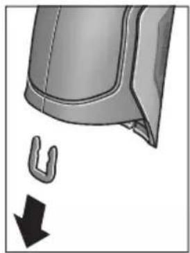
KakoToe npnkaKaHo Ha cnkaTa n3BaTe ja U-cnojkata, KojaTu rN dpxn 3aeHNO KyknWtata.
Odbptete r3abpTKte Ha KyknteTo n3BaTeTe KkyuTeTo co CneuKnaHohata nnouka.
Akymylatopot 3a pe3epBHO ha-nojybahe (konuecta keNja) ce Hara Ha nlaTHATA BO BHaTpeHocTa OD KyknTeTo. N3BaTeTo Od DpKaOT NOTCPaHete To Ha ekONOKN pnpatnNB HauHn.
Ce 3aDpxyBa npaBTo Ha npoMeHa.
Srpski
Uputstva o sigurnosti

Morate da procitate i obratite paznju na sva uputstva kako biste sa altom radili bez opasnosti i bezbedno. Ako merni alat ne upotrebljavate u skladu sa prilozenim uputstvima, mozete da ugrozite zastitne
mere koje su integrisane u merni alat. Nemoje da dozvolite da pločice sa upozorenjima budu nerazumljive.
DOBRO SACUVAJTE OVO UPUTSTVO I PREDAJTE GA ZAJEDNO SA ALATOM, AKO GA PROSLEDUJE TELJE.
- Oprez - ako se koriste drugi uredjaji za rad ili podesavanje od onih koji su ovde navedeni, ili izvode drugi postupci, moze ovo voditi eksplozijama sa zračenjem.
Merni alat se isporucije sa Jednom upozoravajućom tablicom (uprikazu mernog alata označena na grafickoj stranici sa brojem 7).
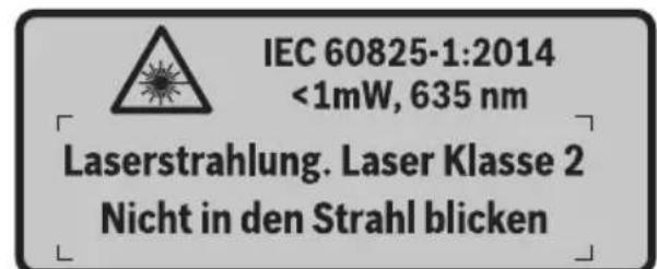
Ako tekst tablice sa opomenom nije na Vasem jeziku, onda prelepite ga pre prvog pustanja u rad sa isporucenom nalepnicom na jeziku Vase zemplje.
Ne usmeravaje laserski zrak na osobe ili ziivotinje i sami ne gledajte u direktan ili reflektujuci laserski zrak. Na taj nacin mozete dazaslepite lica, prouzrokujete nezgode ili da ostetite oci.
Ako lasersko zračenje dode u oko, morate svesno da zatvorite oko i da glavu odmah okrenete od zraka.
Nemojte da vrsite promene na laserskoj opremi.
Ne koristite laserske naocare za posmatranje kao zastitne naocare. Laserske naocare za posmatranje sluze za bolje prepoznavanje laserskog zraka, one ne stite od laserskog zračenja.
Ne upotrebljavaje laserske naoCare za posmatranje kao naoCare za suntce ili u putnom saobracaju. Laserske naoCare za posmatranje ne pruzaju punu UV zastitu i smanjuju opazanje boja.
Neka Vam merni alat popravlja strucno osoblje i samo sa originalnim rezervnim delovima. Time se obezbedjuje, da sigurnost mernog alata ostaje sačuvana.
Henk Becker Helmut Heinzelmann Executive Vice President Head of Product Certification Engineering PT/ETM9

Robert Bosch GmbH, Power Tools Division 70764 Leinfelden-Echterdingen, GERMANY Leinfelden, 16.04.2015
Montaža
Henk Becker Helmut Heinzelmann
Executive Vice President Head of Product Certification
Engineering PT/ETM9

Robert Bosch GmbH, Power Tools Division 70764 Leinfelden-Echterdingen, GERMANY Leinfelden, 16.04.2015
Montaža
Oskrba z energijo
Henk Becker Helmut Heinzelmann Executive Vice President Head of Product Certification Engineering PT/ETM9

Robert Bosch GmbH, Power Tools Division 70764 Leinfelden-Echterdingen, GERMANY Leinfelden, 16.04.2015
Montaža
Elektricno napajanje
Mjerni alat moze raditi suobičajenim baterijama ili s Bosch Li-ionskom aku-baterijom.
Kataloški broj 3 601 K83 370: Mjerni alat moze se koristiti isklučivo s konvencionalnim baterijama.
Rad s baterijama (ne za kataloški broj 3 601 K83 370) (vidjeti sliku A)
Baterije se stavljaju u adapter za baterije.
Executive Vice President Head of Product Certification
Engineering PT/ETM9

Robert Bosch GmbH, Power Tools Division
70764 Leinfelden-Echterdingen, GERMANY
Material Emissoonitase
Material Emissoonitase
| Kroom, poleeritud 0,07 | |
| Katusepapp 0,90 | |
| Klaas | 0,88 |
Henk Becker Helmut Heinzelmann
Executive Vice President Head of Product Certification
Engineering PT/ETM9

Robert Bosch GmbH, Power Tools Division 70764 Leinfelden-Echterdingen, GERMANY Leinfelden, 16.04.2015
Montaža
Elektrobarosana
Henk Becker Helmut Heinzelmann
Executive Vice President Head of Product Certification
Engineering PT/ETM9

Robert Bosch GmbH, Power Tools Division 70764 Leinfelden-Echterdingen, GERMANY Leinfelden, 16.04.2015
Montavimas
LgI JyBjJrJrJrJrJrJrJrJrJrJrJrJrJrJrJrJrJrJrJrJrJrJrJrJrJrJrJrJrJrJrJrJrJrJrJrJrJrJrJrJrJrJrJrJrJrJrJrJrJrJrJ rR J.
Jsuuiu uuiu uo lo abw luc ailul ooo .aigoo
jglgao gao
goo "jogll goo" aoil g elk
o aall o jol l j 00gall c alall
11 ouy | qwll jj lc baoi .dag
aol | acll aai all | jwogll "... joll"
odlc joi 17 wbl ybgl jll lc lo! 10 u2 | ybgl jll lc g i, ciaolall gao
. aolal | la ly dao lc joi
jIJI UlogJoo
Lc wy pa wqal ooc Ugoglo 1Ugauu
pJl Lg .jQaI Iogoo" aCJAL dAaJI
. qaiI gol jI sOg wqal Oe JwuaJI
:labk1 Cg
aiojll jiai lla "labg" aolg g elisao 1s Icsloggi wgl osc labI loo pssw yll 1a! laeisog. JjJx no sI cIbdoal ppo 10 g jiai I x no .Svlogg Iabx aIoo 15 bgaai Iabx Cg jao Ials .Lalbo" bai I .
:δ:L@
aiojll ojiall jaiia "oLxoldo" aaf g elks
jogjol oag oolggbw dajl lalai paa w jil
. waii ooi jj1o 1c baoaill pai 13
Jooq Jksw jorjll oag ool' lai elkaog
oLxolooo o0o qoq oLs. "lais" bawg jai
. uS1 Uksw agbll jggi ksoy
UgI -
| الإستعمال | الإستعمال | الإستعمال |
| .شامبملاوي بطرير محيى و پورن الحرفية بطرير محيى并与 رسمعه نه;/ .شامبملاوي بطرير محيى并与 رسمعه نه;/ .شامبملاوي بطرير محيى并与 رسمعه نه;/ .شامبملاوي بطرير محيى并与 رسمعه نه;/ .شامبمleaوي بطرير محيى并与 رسمعه نه;/ .شامبمleaوي بطرير محيى并与 رسمعه نه;/ .شامبمleaوي بطرير محيى并与 رسمعه نه;/ .شامبمleaوي بطرير محيى并与 رسمعه نه;/ .شامبمleaوي بطرير محيى并与 رسمعه نه;/.شامبمleaوي بطرير محيى并与 رسمعه نه;/.شامبمleaوي بطرير محيى并与 رسمعه نه;/.شامبمleaوي بطرير محيى并与 رسمعه نه;/.شامبمleaوي بطرير محيى并与 رسمعه نه;/.شامبمleaوي بطرير محيى并与 رسمingtonالله./.شامبمleaوي بطرير محيى并与 رسمingtonالله./.شامبمleaوي بطرير محيى并与 رسمingtonالله./.شامبمleaوي بطرير محيى并与 رسمingtonالله./.شامبمleaوي بطرير محيى并与 رسمingtonالله./.شامبمleaوي بطرير محيى并与 رسمingtonالifica./.شامبمleaوي بطرير محيى并与 رسمingtonالifica./.شامبمleaوي بطرير محيى并与 رسمingtonالifica./.شامبمleaوي بطرير محيى并与 رسمingtonالifica./.شامبمleaوي بطرير محيى并与 رسمingtonالifica./.شامبمleaوي بطرير محيى并与 رسمingtonالffa./.شامبمleaوي بطرير محيى并与 رسمingtonالffa./.شامبمleaوي بطرير محيى并与 رسمingtonالffa./.شامبمleaوي بطرير محيى并与 رسمingtonالffa./.شامبمleaوي بطرير محيى并与 رسمingtonالffa./.شامبمleaوي بطرير محيى并与 رسمingtonالff./.شامبمleaوي بطرير محيى并与 رسمingtonالff./.شامبمleaوي بطرير محيى并与 رسمingtonالff./.شامبمleaوي بطرير محيى并与 رسمingtonالff./.شامبمleaوي بطرير محيى并与 رسمingtonالff./.شامبمleaوي بطرير محيى并与 رسمingtonال ff./.شامبمleaوي بطرير محيى并与 رسمingtonال ff./.شامبمleaوي بطرير محيى并与 رسمingtonال ff./.شامبمleaوي بطرير محيى并与 رسمingtonال ff./.شامبمleaوي بطرير محيى并与 رسمingtonال ff./.شامبمleaوي بطرير محيى并与 رسمingtonالff./.شامبمleaوي بطرير محيى并与 رسمingtonالff./.شامبمleaوي بطرير محيى并与 رسمingtonالff./.شامبمleaوي بطرير محيى并与 رسمingtonالff./.شامبمleaوي بطرير محيى并与 رسمingtonال off./.شامبمleaوي بطرير محيى并与 رسمingtonال off./.شامبمleaوي بطرير محيى并与 رسمingtonال off./.شامبمleaوي بطرير محيى并与 رسمingtonال off./.شامبمleaوي بطرير محيى并与 رسمingtonال off./.شامبمleaوي بطرير محيى并与 رسمingtonالoff./.شامبمleaوي بطرير محيى并与 رسمingtonال off./.شامبمleaوي بطرير محيى并与 رسمingtonال off./.شامبمleaوي بطرير محيى并与 رسمingtonال off./.شامبمleaوي بطرير محيى与 | .شامبمleaوي بطرير محيى与 .شامبمleaوي بطرير محيى与 .شامبمleaوي بطرير محيى与 .شامبمleaوي بطرير محيى与 .شامبمleaوي بطرير محيى与 .شامبمleaوي بطرير محيى与 .شامبمleaوي بطرير محيى与 .شامبمleaوي بطرIRMالدانيت/. .شامبمleaوي بطرIRMالدانيت/. .شامبمleaوي بطرIRMالدانيت/. .شامبمleaوي بطرIRMالدانيت/. .شامبمleaوي بطرIRMالدانيت/. .شامبمleaوي بطرIRMالدانيت/. .شامبمleaوي بطرIRMالدانيت/. .شام葆مleaوي بطرIRMالدانيت/. .شام葆مleaوي بطرIRMالدانيت/. .شام葆مleaوي بطرIRMالدانيت/. .شام葆مleaوي بطرIRMالدانيت/. .شام葆مleaوي بطرIRMالدانيت/. .شام葆مleaوي بطرIRMالدانيت/. .شام葆مleaوي btt. .شام葆مleaوي btt. .شام葆مleaوي btt. .شام葆مleaوي btt. .شام葆مleaوي btt. .شام葆مleaوي btt. .شام葆مleaوي btt. .شام葆مleaوي btt. .شام葆مleaوي btt. .شام葆مleaوي btt. .شام葆مleaوي b tt. .شام葆مleaوي btt. .شام葆مleaوي btt. .شام葆مleaوي btt. .شام葆مleaوي btt. .شام葆مleaوي btt. .شام葆مleaوي btt. .شام葆مleaوي btt. .شام葆مleaوي btt. .شام葆مleaوي btt. .شام葆مleaوي b t. .شام葆مleaوي btt. .شام葆مleaوي btt. .شام葆مleaوي btt. .شام葆مleaوي btt. .شام葆مleaوي btt. .شام葆مleaوي btt. .شام葆مleaوي btt. .شام葆مleaوي btt. .شام葆مleaوي btt. .شام葆مleaوي bt. .شام葆مleaوي btt. .شام葆مleaوي btt. .شام葆مleaوي btt. .شام葆مleaوي btt. .شام葆مleaوي btt. .شام葆مleaوي btt. .شام葆مleaوي btt. .شام葆مleaوي btt. .شام葆مleaوي btt. .شام葆مleaوي bTT. .شام葆مleaوي btt. .شام葆مleaوي btt. .شام葆مleaوي btt. .شام葆مleaوي btt. .شام葆مleaوي btt. .شام葆مleaوي btt. .شام葆مleaوي btt. .شام葆مleaوي btt. .شام葆مleaوي btt. .شام葆مleaوي b. .شام葆مleaوي btt. .شام葆مleaوي btt. .شام葆مleaوي btt. .شام葆مleaوي btt. .شام葆مleaوي btt. .شام葆مleaوي btt. .شام葆مleaوي btt. .شام葆مleaوي btt. .شام葆مleaوي btt. .شام葆mleaوي btt. .شام葆mleaوي btt. .شام葆mleaوي btt. .شام葆mleaوي btt. .شام葆mleaوي btt. .شام葆mleaوي btt. .شام葆mleaوي btt. .شام葆mleaوي btt. .شام葆mleaوي btt. .شام葆mleaوي btt. .شام葆 mleaوي btt. .شام葆 mleaوي btt. .شام葆 mleaوي btt. .شام葆 mleaوي btt. .شام葆 mleaوي btt. .شام葆 mleaوي btt. .شام葆 mleaوي btt. .شام葆 mleaوي btt. .شام葆 mleaوي btt. .شام葆 mleaوي btt. .شام葆mleaوي btt. .شام葆 mleaوي btt. .شام葆 mleaوي btt. .شام葆 mleaوي btt. .شام葆 mleaوي btt. .شام葆 mleaوي btt. .شام葆 mleaوي btt. .شام葆 mleaوي btt. .شام葆 mleaوي btt. .شام葆mleaوي btt. .شام葆mleaوي btt. .شام葆 mleaوي btt. .شام葆 mleaوي btt. .شام葆 mleaوي btt. .شام葆 mleaوي btt. .شام葆 mleaوي btt. .شام葆 mleaوي btt. .شام葆 mleaوي btt. .شام葆mleaوي btt. .شام葆 mleaوي btt. .شام葆mleaوي btt. .شام葆 mleaوي btt. .شام葆 mleaوي btt. .شام葆 mleaوي btt. .شام葆 mleaوي btt. .شام葆 mleaوي btt. .شام葆 mleaوي btt. .شام葆 mleaوي btt. .شام葆mleaوي btt. .شام葆mleaوي btt. .شام葆mleaوي btt. .شام葆 mleaوي btt. .شام葆 mleaوي btt. .شام葆 mleaوي btt. .شام葆 mleaوي btt. .شام葆 mleaوي btt. .شام葆 mleaوي btt. .شام葆mleaوي btt. .شام葆 mleaوي btt. .شام葆 mleaوي btt. .شام葆mleaوي btt. .شام葆 mleaوي btt. .شام葆 mleaوي btt. .شام葆 mleaوي btt. .شام葆 mleaوي btt. .شام葆 mleaوي btt. .شام葆 mleaوي btt. .شام葆mleaوي btt. .شام葆 mleaوي btt. .شام葆mleaوي btt. .شام葆mleaوي btt. .شام葆 mleaوي btt. .شام葆 mleaوي btt. .شام葆 mleaوي btt. .شام葆 mleaوي btt. .شام葆 mleaوي btt. .شام葆 mleaوي btt. .شام葆mleaوي btt. .شام葆mleaوي btt. .شام葆 mleaوي btt. .شام葆mleaوي btt. .شام葆 mleaوي btt. .شام葆 mleaوي btt. .شام葆 mleaوي btt. .شام葆 mleaوي btt. .شام葆 mleaوي btt. .شام葆 mleaوي btt. .شام葆mleaوي btt. .شام葆mleaوي btt. .شام葆mleaوي btt. .شام葆mleaوي btt. .شام葆 mleaوي btt. .شام葆 mleaوي btt. .شام葆 mleaوي btt. .شام葆 mleaوي btt. .شام葆 mleaوي btt. .شام葆mleaوي btt. .شام葆 mleaوي btt. .شام葆 mleaوي btt. .شام葆 mleaوي btt. .شام葆mleaوي btt. .شام葆 mleaوي btt. .شام葆 mleaوي btt. .شام葆 mleaوي btt. .شام葆 mleaوي btt. .شام葆 mleaوي btt. .شام葆mleaوي btt. .شام葆 mlea蜃 .شام葆 mlea蜃 .شام葆 mlea蜃 .شام葆 mlea蜃 .شام葆 mlea蜃 .شام葆 mlea蜃 .شام葆 mlea蜃 .شام葆 mlea蜃 .شام葆 mlea蜃 .شام葆 mlea蜃 .شام葆 mlea蜃 .شام葆 mlea蜃 .شام葆 mlea蜃 .شام参保 .شام参保 .شام参保 .شام参保 .شام参保 .شام参保 .شام参保 .شام参保 .شام参保 .شام参保 .شام参保 .شام参保 .شام参保 .شام参保 .شام参保 .شام参保 .شام参保 .شام参保 .شام参保 .شام参保 .شام投保 .شام投保 .شام投保 .شام投保 .شام投保 .شام投保 .شام投保 .شام投保 .شام投保 .شام投保 .شام投保 .شام投保 .شام投保 .شام投保 .شام投保 .شام投保 .شام投保 .شام投保 .شام投保 .شام投保 .شام参保 .شام参保 .شام参保 .شام参保 .شام参保 .شام参保 .شام参保 .شام参保 .شام参保 .شام参保 .شام参保 .شام参保 .شام参保 .شام参保 .شام参保 .شام参保 .شام参保 .شام参保 .شام参保 .شام保费 .شام保费 .شام保费 .شام保费 .شام保费 .شام保费 .شام保费 .شام保费 .شام保费 .شام保费 .شام保费 .شام保费 .شام保费 .شام保费 .شام保费 .شام保费 .شام保费 .شام保费 .شام保费 .شام保费 .شام投保 .شام投保 .شام投保 .شام投保 .شام投保 .شام投保 .شام投保 .شام投保 .شام投保 .شام投保 .شام投保 .شام投保 .شام投保 .شام投保 .شام投保 .شام投保 .شام投保 .شام投保 .شام投保 .شام 报告 .شام 报告 .شام 报告 .شام 报告 .شام 报告 .شام 报告 .شام 报告 .شام 报告 .شام 报告 .شام 报告 .شام 报告 .شام 报告 .شام 报告 .شام 报告 .شام 报告 . .شام 报告 .شام 报告 .شام 报告 .شام 报告 .شام 报告 .شام 报告 .شام 报告 .شام 报告 .شام 报告 .شام 报告 .شام 报告 .شام 报告 .شام 报告 .شام 报告 .。 . . . . . . . . . . . . . . . . . . . . . . . . . . . . . . . . . . . . . . . . . . . . . . . . . . . . . . . . . . . . . . . . . . . . . . . . . . . . . . . . . . . . . . . . . . . . . . . . . . . . 、 . . . . . . . . . . . . . . . . . . . . . . . . . . . . . . . . . . . . . . . . . . . . . . . . . . . . . . . . . . . . . . . . . . . . . . . . . . . . . . . . . . . . . . . . . . . . . . . . . . . ? . . . . . . . . . . . . . . . . . . . . . . . . . . . . . . . . . . . . . . . . . . . . . . . . . . . . . . . . . . . . . . . . . . . . . . . . . . . . . . . . . . . . . . . . . . . . . . . . . . . ; . . . . . . . . . . . . . . . . . . . . . . . . . . . . . . . . . . . . . . . . . . . . . . . . . . . . . . . . . . . . . . . . . . . . . . . . . . . . . . . . . . . . . . . . . . . . . . . . . . . - . . . . . . . . . . . . . . . . . . . . . . . . . . . . . . . . . . . . . . . . . . . . . . . . . . . . . . . . . . . . . . . . . . . . . . . . . . . . . . . . . . . . . . . . . . . . . . . . . . . - 2017年1月1日 - 2017年1月1日 - 2017年1月1日 - 2017年1月1日 - 2017年1月1日 - 2017年1月1日 - 2017年1月1日 - 2017年1月1日 - 2017年1月1日 - 2517年1月1日 - 2517年1月1日 - 2517年1月1日 - 2517年1月1日 - 2517年1月1日 - 2517年1月1日 - 2517年1月1日 - 2517年1月1日 - 2517年 - 2517年 - 2517年 - 2517年 - 2517年 - 2517年 - 2517年 - 2517年 - 2517年 - 2517年 - 2517年 - 2517年 - 2517年 - 3017年 - 3017年 - 3017年 - 3017年 - 3017年 - 3017年 - 3017年 - 3017年 - 3017年 - 3017年 - 3017年 - 3017年 - 3017年 |
JuiiI JuiI Koi! jo Jo Suu Ie WsI 13!
juaI gog jIgblp uuuu, Soo aiaa qiu
bouai I buai I gog jusu .nagw nn ylll
Jauu I quuui JJ g15 uuuu paaal jj Uc
Eswu kswy dssu wuauu paai 11
.ubgsao iieall qauuJJ cbaiaii []

gJ Ljw J 15 wJ jLc
JyI P W J11 JwJ jLc
JyI gJ J. "J" JgJ
JyI P W J11 JwJ jLc
JyI gJ J. "J" JgJ
JyI Jn JwJ jLc
9 JwJ/0jSJJjLc
gunll 11111111111 17 1111111111 0jlaal lgl 11111

LcSsbyo aal oocn bLatll "aaiill" (Jaiill) "aaiill aaiill" 6g 1e "Bluetooth" aabg bpag (400 aao 1d .f nnall jol g yp . "jaiill". Jaiill jlg yda aoi Bltooth aaiil alg Jiaoo jaiill jajll jalg paaegwgl O. Appss) wgo tappb jg Tuiill :aaii jaiill

Available on the
App Store
ANDROID APP ON
Google play
JlJIJI JIJI JIJI JIJI JIJI JIJI JIJI JIJI JIJI JIJI JIJI JIJI JIJI JIJI JIJI JIJI JIJI JIJI JIJI JIJI JIJI JIJI JIJI JIJI JIJI JIJI JIJI JIJI JIJI JIJI JIJI JIJI JIJI JIJI JIJJJJJJJJJJJJJJJJJJJJJJJJJJJJJJJJJJJJJJJJJJJJJJJJJJJJJJJJJJJJJJJJJJJJJJJJJ
"duuJJdaiJlJ
“auiuJl aoiJaiJ”LjaiJl
g bai" aui jll aiai" uI UgogU - 10

Jg aalll 1aagaa Jd Jaiil
jjg16 gall pawll jj Lc baaill
syy dpo j113 lawl pawll
jao ngly ogcrall aalll
aal jla aeg aol glls 1j
jgb uo ell jau paae,
Uoggl.“...u"uaynnaaag
qall jj lc baxl, aucjll aaiaaJ
11 n

"“auiuui aaii"Lc sWu oJ uJ 1 Jaiil
aaii j.400 aoo, "auiuui aoiiai"J iaiil
"paaiuill aaij" Lg jalg "auiuill aucjll
aiai Iwgoo" Uuiuul fai g l uuui liu elkog
9 "unlall aajg"g "Iggl aigj"g "JlJI
.
.1JJI JJI JJJ "JISJLJJ" Si Cn JbI - 1JJI JJJ JJJ JJJ JJJ JJJ JJJ JJJ JJJ JJJ JJJ JJJ JJJ JJJ JJJ JJJ JJJ JJJ JJJ JJJ JJJ JJJ JJJ JJJ JJJ JJJ JJJ JJJ JJJ JJJ JJJ JJJ JJJ JJJ JJJ JJJ JJJ JJJ JJJ JJJ JJJ JJJ JJJ JJJ JJJ JJJ JJJ JJJ JJJ JJJ JJJ Jjj
JlI 1
400aa,“gJU/(gJ”jI:gJ/(JU 404a,"gbsu
- wluJj

aJjUJawlJ (juaal) uJdJI

j00g j00g j00g j00g j00g j00g j00g j00g j00g j00g j00g j00g j00g j00g j00g j00g j00g j00g j00g j00g j00g j00g j00g j00g j00g j00g
aJyiaaiall aalll jss Jnssnnn 1 1 1 1 1 1 1 1 1 1 1 1 1 1 1 1 1 1 1 1 1 1 1 1 1 1 1 1 1 1 1 1 1 1 1 1 1 1 1 1 1 1
Jusu Jds uJ. e juJg aJUJJ Js Jj Uc bao1 16 sglJ qwJ jj Uc boJ 13 LowJ pWJ
wulalbawo
a aal l k s o aal b a 1 p j w yll s ic
sclw u n k s o g .dwl l u g i o o j c nn m 24
jg0 n jdt sic l aqai qi j U gogll j d J.
14 jll 24 aalal .labg l w jol
lo sic ,aglal ggl alal .lablg llogig p
jai kog . oag o sag o! Egbaw dJ uoi p
o"blil) "oLkdo" aoI I g o oos ofo I oo
Lslogigal auall Jw p yx .(399 aaoo, "oLk
. oajll oag o! Lssw oJc
aui p x q g ubi g pSoll n w aa cIs I
. aglal ggl g g
山
山
aagg no wuul 0e de aie gce jn .alwgl aeg
g 1 gss sll lal jai y aai ll o dsc s k s s s s s s s s s s s s s s s s s s s s s s s s s s s s s s s s s s s s s s s s s s s s s s s s s s s s s s s s s s s s s s
.15 11 aalj
gddwcbdowwqalldscjyjzj 1 gaaaiaa aaiuul oauo aai y .bgaw 009ybiu ksskui jai ggl 111 daaiaaii iaoi do sjsjdo w q
Lj .aSsw 2 aBg o gjo wlaal osc
9 lall sWg
. uawwll gI UJbI
abg
Jgdsawl JlaaWdWsc J21 aIalI IbcI g 19 aIalI bG 23 Jauu 5 aIaI Jauu g 23 Jauu 22 Jauu g 5
jj 12 18 18
18
18
18
18
18
18
18
18
18
18
18
aJgD gWgll 8 J
LacPd .LaaswI dy Wgll 0cblg
JJU Ew wJnJy Jw
gulglgJjUeJgUeJg
eogj g jol oag oolggbw aJd Jai pui
ggi jglj jabu 30 30 gauaJI bao
o! jss w yjj 1c 1sdo bsal sicg .aJIJI
loxl o so jooi kag .alolll qsw jorell oag "oLx" 1bil) "oLx" aoJIall 9 o.
(399
aiaiI p9mu gio mu) aJU go Jusuill
(BgJgJIgIj) (3601K83370
oJd aJIO JI I JI JI JI JI JI JI JI JI JI JI JI JI JI JI JI JI JI JI JI JI JI JI JI JI JI JI JI JI JI JI JI JI JI JI JI JI JI JI JI JI JI JI JI JI JI
J Jn Jn Jn Jn Jn Jn Jn Jn Jn Jn Jn Jn Jn Jn Jn Jn Jn Jn Jn Jn Jn Jn Jn Jn Jn Jn Jn Jn Jn Jn Jn Jn Jn Jn Jn Jn Jn Jn Jn Jn Jn Jn Jn Jn Jn Jn Jn Jn Jn Jn J n
0g5dall jaiil 0jai lai
jg jn nn jj. qal lal gall 9
lal pugll uig jgo aolglll 10
. yaoa oia oia oic o
J 1 J 2 J 3
JolgX Wulll 5d JsIlogg 1 cGgl l sJl I li .09 .labxlg Jj Lc b
U 29 30 1J 1J 1J 1J 1J 1J 1J 1J 1J 1J 1J 1J 1J 1J 1J 1J 1J 1J 1J 1J 1J 1J 1J 1J 1J 1J 1J 1J 1J 1J 1J 1J 1J 1J
(3601K83370) 1JJI abwIg jI (C gglj)
3 31 32
a aagggl oleo 1uulbll uysi sic jol
. uul bll 3 10 gall oogall lalb ula
aslg 31 uulbll 3 10 25u
b9 p sww. 1g g uJbU g aJbU .aWJuai g eii Juao joo UjU
Iglosiwi pse sic wai jol oec jc ujll Eji 1 ojiia sic ujlluul Jsw .algb ojial
Lgai jia jaoj gao adugb
Jaiu
jw aIg jJg gJwI aIa Jn mJw.30 pJg
Executive Vice President
Head of Product Certification
Engineering
PT/ETM9

Robert Bosch GmbH, Power Tools Division 70764 Leinfelden-Echterdingen, GERMANY
wll scc ploaewu uaaoo aubll Lgq
.ajiljgJl JdJgdoJdJwI jgJgJg
27 1JU JU UJU JU
0gJU L 29 1
yj 28 aJJI. 1c o gagll
golo kuiyui jai yai jia liuai libc
uulai ooc uao 20 abluw
jlljjl lbcbso1uJJbUeJ
aLaJI 15c gjilg 28 aLaJI 13
- 1.
jngs yu wlaol osc elom joll. uulll aal .uI l I lego 29 pss
29 27 1234567890123456789012345678901234567890123456789012345678901234567890123456789012345678901234567890123456789
baq p daiw .dag u g u j bui gaa Jdu w
aJUoai g aiai JUo UjIb
Ljlosiw psc sic wlaal 6c jc UJbll gji
jol qijiaic uylbllusd .algbo jol
Lguai jgjooogaiagb
| GIS 1000 C | GIS 1000 C | الشام الحير |
| 1:50 | 1:50 | (3)(4)(5)(6)(7)(8)(9)(10)(11)(12)(13)(14)(15)(16)(17)(18)(19)(20)(21)(22)(23)(24)(25)(26)(27)(28)(29)(30)(31)(32)(33)(34)(35)(36)(37)(38)(39)(40)(41)(42)(43)(44)(45)(46)(47)(48)(49)(50)(51)(52)(53)(54)(55)(56)(57)(58)(59)(60)(61)(62)(63)(64)(65)(66)(67)(68)(69)(70)(71)(72)(73)(74)(75)(76)(77)(78)(79)(80)(81)(82)(83)(84)(85)(86)(87)(88)(89)(90)(91)(92)(93)(94)(95)(96)(97)(98)(99)(100) |
| 2 | 2 | ديره پوری |
| \( \text{ملاoverview} \)1 > ,رطامعی 635 | \( \text{ملاoverview} \)1 > ,رطامعی 635 | (الشام الحيری) پوری |
| \( \text{ملاoverview} \)6\( \text{ملاoverview} \)10 | \( \text{مleaoverview} \)10 | (الشام الحيری) پوری |
| LR6 (AA) بورگ 1,5x4- | LR6 (AA) بورگ 1,5x4\( (\text{ملاoverview}) \) | (الشام الحيری) پوری |
| \( \text{ملاoverview}) \)10,8 | (الشام الحيری) پوری | |
| \( \text{ملاoverview} \)3- | \( \text{مleaoverview} \)5 | (الشام الحيری) پوری |
| \( \text{مleaoverview}) \)200 | (الشام الحيری) پوری | |
| \( \text{مleaoverview} \)5 (Low Energy g Classic) | \( \text{مleaoverview}) \)2.0 | USB äوری |
| \( \text{مleaoverview} \)0.55 | \( \text{مleaoverview}) \)≤0.55 | EPTA-Procedure 01/2003 |
| \( \text{مleaoverview} \)214x89x136 | \( \text{mxaoverview}) \)214x89x136 | (الشام الحيری) پوری |
| - -10...+50°C -20...+70°C | 0...+45°C -10...+50°C -20...+70°C | (الشام الحيری) پوری |
| - | GBA 10,8V ... | (الشام الحيری) پوری |
| - | AL 11...CV | (الشام الحيری) پوری |
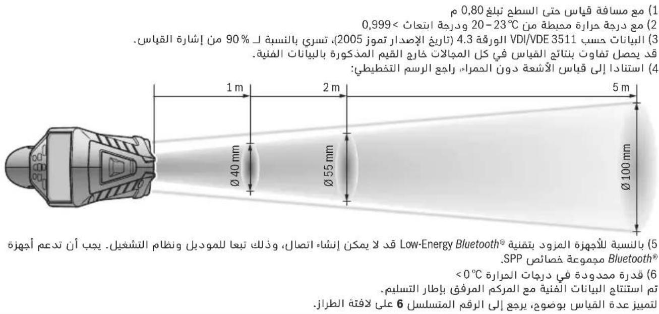
abaaJ oJolJ aJg slgJ aJb jwuu 5
JulwuiJI 6
JUUL-1a 7
8
Bluetooth 9
j0g1 jjj1 10
jai qaii jj 11
labg uusuul eloo 12
JSSaJ JAnS/LoawI qWJj 13
labg jj 14
Juu1 aqwUJJ 15
JSSJdssj/1gglJgWJjj 16
Jj1 17
awwul 18
0jIJIgglgjjgbljwuuuulac 19
abaaol
Jaaabgui jda 20
JaaJgssawsulwawwauasu21
UoLSU 22
Jg aawj Juaaawsc 23
24
sJJJ JauisK ggiJoo aLg 25
gSLo USB 26
27
UJUJI UaUaUaUa28
aJaiu 29
aJ 30
UJUBJI 31
olgooJpawJI gddggagllgagogllglll
15uic2I ujjlllub!
Ig aiaJ Iog
wIaIbOscgwsyogjallaaalllaaai
.1JaaW2I aWlS b-1g -aagao Lqsjg
JusaiJusai
jg 100
1gUauiuJI aBglg abaaJl JJJ aJg
jgwwlll oJwXlg sill abai ywiia ly oogai
JooJgJgJooJgJooJgJoo
.1aiI 101 1auiJiaU Ioo
joo JJJwogssjjllbai jol sawl jgny 2
wll gbw jou lc lqol w
oJgaaJI 1j
wI 0sc gws JgjgssJi
aIbIbail gWJl aow lc oogagall
(Kggl) jpaic aIog/gSLo USB 1
jjlll 2
3
JJJ/luJJJ 4
aaiuui
ggljgjggl-wwl 1
Lgllw! gllim LjS jll
. 1
P) aJyao go wlaal ooc wto
pogwll aagc yagaa lgljw
.(7 pJIyababil
IEC60825-1:2014 <1mW, 635 nm
S OJSJ S W U S OJS
Gblo J diy jgs J
. JU J
JgJ Jd y sJ 5g
Wgj gbo J diy jgs
. JSJ J
:ss jai
0iiS cJjUJJJJSS 59 JJJUd s ss C
CJUJJJJJJJJJJJJJJJJJJJJJJJJJJJJJJJJJJJJJJJJJJJJJJJJJJJJJJJJJJJJJJJJJJJJJJJJJJJJJJJJJJJJJJJJJJJJJJJJJJJJJJJJJJJJJJJJJJJJJJJJJJJJJJJJJJJJJJJJJJJJJJJJJJJJJJJJjj JJJJJJJJJJJJJJJJJJJJJJJJJJJJJJJJJJJJJJJJJJJJJJJJJJ
Ssi duiu jJ 5j SjSj oJ si Jjai a jji goo j .sui jj (laleo) iai cS l
pLa oLg
jglo lso
LblisogjS1g jy jor jg slo slojS gjg lo d gjJd.0g w o JwJpJd S cwi .Jl SsiW pW abw 5 a
abw 5 aJ
Ssun 1abw jlaow g w yabw abw s dJ
uglo lsoj Sgjj JdS no Jw j.
oLW pws) jS Jljo gjj L aaw lao J j W j0j
. Si o Uloi k = 1 abw da
jJU
du loj dawgali ds s ggo yu wdy jyur yu yu yu yu yu yu yu yu yu yu yu yu yu yu yu yu yu yu yu yu yu yu yu yu yu yu yu yu yu yu yu yu yu yu yu yu yu yu yu yu yu yu yu yu yu yu yu yu yu yu y u
guiygbj
UJLgJgdsSsUunuUcgbj UoJlglicOUsJdso.UsIoo UJgLo gdsUJyJdo
LsduuJyI JSSO uJus. yDyUo pJ, sIS
SuuuuyuJyIgM, uWuJusuLydsu:Usu
. dS U
Sj j jg jbs, sly slj lgw ciwi ggbj djiu JiooLJyIuysIgWcgbj.duL Go uJj .si
piw is abai sls
U 1234567890
U 1234567890
U 1234567890
U 1234567890
U 1234567890
U 1234567890
U 1234567890
U 1234567890
U 123456
:Jgjogoljooj
1oJydiIg JooOogolooj" CwJ 1
du oJl jJl dJl JdS,ds SlaJI Jloj
da s ds Jgog J, gW owol JsGg JgB
Jc I JsGg B OJgi Loaw .gwi OJg W
Uaill J《j》oAobii dS Ogaii D,siL J20
JuDg Wogola JooJ uoi IgS aJw Uaill L. dS L
.ogw Goo
:Liwjoo
jloj s oju d jgi g Oo "Liwog" Cwsg J S 1 g b y s s ojdl jbjd sij jds i klaill I s da s ds gogos gogolkgs liuog jsi ggo gdoa .gogoo j 《“Duaom”Caaabdtc o gos no bsis xiaoj liuog jnloj uigg a jai l .siklaai
:glaosdooJSLy
Jg Jg 10 CwJg 10
:
lKimU LLoI CwJg@ d jjj
SjSLACdoSSjSjLwIgzi da
.1jwJm CwJg CooLjc 10
UdoJ,uwjg2awJwS
13 uu u u 16 2u u
olgdswqgbsuwsjwqjai
.8gddiuuyj jjg
jliuwwg jS ggsgjj
duuLuyuOduaow
.8gwhoohoawu laui lao
a CwSjg《Lol CwJg》Sj Cg
WLa" Cwqg j J oIgJds JaS S
aJ3>g《uUj05uJaJ3>J<
Jsaoojusg juiuui k Juiu lai j .sia paai 24
.igwGjWbGJWsOswos
jguai dao sIgusc Uio uIgic dyu gjo agsui
Ugq coLc sduwgyj caliao 1s oJsi
Jdawlao
aao yogj Ug jg j 5uJ L Jyagj
15 u 100
J11 cWJ Jd aS L
JSSGoo. 1s8 jolb oig s agi l aHJS
UJSS Lao Cg. Sua Juiig 9 Oa s daos aogj
oJlJS aos. 5g oJl Sg jg g aogj
J 4
4 1s jol 1s do s J 0jplai jw .Jw jjo
.igw o ods juw osw uaiil
Uebl Jai
USBJlaIgduwgyIeIbIJIaI
ojiljlmicro-USB26JlJ1JJ1J11g
LduiJd8JWjMicro-USB JLSgUwBjIy
JPG 100000000000000000000000000000000000000000000000000000000000000000000
LduiJdUSBUcIuIbOjUjIjI:dg
uJUaiUjgOJS.1S Uaio (Uli U) LAsL dui
.1iui o1iws cwi jSao Lsiw s JI
olj jUgj Gai JsS oJsi JjI sJlW sJyL aagj
egj sjjw sjiu jlw Cg .sjjw USB uai l
419 aaaa, 山 1w 山 li LgJslolj
JooLc dS Jdo jI JLos aJlsl aJg Jo laW
.5uS puiu g w L o01s uuj joi 5oog
(g)gJg“Lolwjg”dyjgbio 1
CwJgJjJ.413a0o,<
1sloj(JjJU)J.S.JS JIJI (LssLac
suiS auii jolgul
.1J1J10gssuJ JsJgjIa Sw, gJgJgJ
piw 1slo s abai Jla
15g0 ugbj g bdo 1slos naiw 1slos 1aabai Jds
gwh 10 10j1 j2bw 10s 10j 10g1c .gwh
Jdsduu g duyloabw llos L piaiw s abai slos
JgW Jmuai jLj bla abj
jgiS bIJw Sjduaam sOjI jai li dSsiS c
oJ. Coo jloj y oJil i
jSjS oJsiI iwi ly slaic I Jg SjS oJsiI
dsj jolil ggugg aogj uJs
. 1JU4 j4 oJjL
aJgacIjIjlgSsJwJwJ45uOjxldo
1slo jSjOjI jol pai jI Jw Jy Sj Jo
sloso 5uuiai jso w s uw w uai
aau lao I J Ld sgs g 0jI jI ddd Sds (5g) q coIc I J Ld sao mai g Si :saw 00 sla
<3,5°Cloj@lial)jμwSogssqωlc :
. 6,5°C 3,5°C 1234567890123456789012345678901234567890123456789012345678901234567890123456789012345678901234567890123456789
aoss sJSSyj jS JsJg Cq - .ssJluu jjuoo10 1sLac 15
a uuSjU g UJL b uO uo o j Sj Uj - 17 uu Slaoc u doS uo ojui UJ .uuu Jluu C uuSjU c uj


JyI J OoOg J 100000000000000000000000000000000000000000000000000000000000000
abw llos
Sg oJlJl Gw SbW GsOg W OJL J
. g W
L y 0 w e Lg jg jg jn jy Cll J
. gai i yj l g g uil sl gl
D pgi U g o s bW GsOu Cll J uag
Ua I d aai . Dj B Jd jilw J kui lai
Oo bi y J uag | 11 cwi J uag | aas | 15
Goo C qu . Jbl oigg uog u "abw GsO
Goo C gauu J 9 oua J d aos uog u
I aos uq ojlil cyg w g g w n jk
. uu4 4 6uol
du ogac | jljg g uag | 4 6uok ojlil g da
Igos uq ojlil plai j uay . dyuoy jy
Goo 0 kui lai j do w g uow ujia abw
. sg
oJlJl GsO ujia , sao GsO oJlJl sgo j
GOJU Ld iuy d yu d yu q coLc ly o uw
Jy GsO oJlJl Jf J do s aiuuy g acus . sg
Jy Juaa fiaia d axu y duu w go u J
Jy Jy Jy Jy Jy Jy Jy Jy Jy Jy Jy Jy Jy Jy Jy Jy Jy Jy Jy Jy Jy Jy Jy Jy Jy Jy Jy Jy Jy Jy Jy Jy Jy Jy Jy Jy Jy Jy Jy Jy Jy Jy Jy Jy
abw [slo]
Jg Egs J gJ 0jJ jI J I J I J I J J
jol jj1s 1s 1s 1s 1s 1s 1s 1s 1s 1s 1s 1s 1s 1s 1s 1s 1s 1s 1s 1s 1s 1s 1s 1s 1s 1s 1s 1s 1s
. 1 . 1 . 1 . 1 . 1 . 1 . 1 . 1 . 1 . 1 . 1 . 1 . 1 . 1 . 1 . 1 . 1 . 1 . 1 . 1 . 1 . 1 . 1 . 1 . 1 . 1 . 1 . 1 . 1 . 1 . 1 . 1 . 1 . 1 .
j jw u wu wu wu wu wu wu wu wu wu wu wu wu wu wu wu wu wu wu wu wu wu wu wu wu wu wu wu wu wu wu wu wu wu wu wu wu wu wu wu wu wu wu wu wu wu wu wu wu wu wu wuu
j0j1j1 jlogil u w gola ju
si g u j. 1j Jg g 2g s daS .g w 5j y d w
30 30 1s 1s 29
3 0sis jI sLo aos 30 sJw sJy bJw dJy Jg 29 sJy sdaa oJ I sJw gJw Jg Jg
(3601K83370) (SjU L jSjIolj (Cgaw a gw gJ)
Executive Vice President
Engineering
Head of Product Certification
PT/ETM9
![BOSCH GIS 1000 C Professional - abw [slo] - 1](/content/2026/03/428834/images/fc719b0f63bca3253d4b8d26adac15977b6e85e4fce7ec6db4da9c0618014191.jpg)
Robert Bosch GmbH, Power Tools Division
70764 Leinfelden-Echterdingen, GERMANY
(Kg)JJJ Micro-USB JJJ
jguagaa(aIoo)saio 2
i
| GIS 1000 C | GIS 1000 C | a i w l a s |
| 3 601 K83 370 | 3 601 K83 3.. | c i w l a w |
| 0,1-5 m | 0,1-5 m | d i w l a w |
| e i w l a w | ||
| -40...+1000°C | -40...+1000°C | f i w l a w |
| -40...+1000°C | -40...+1000°C | g i w l a w |
| -10...+50°C | -10...+50°C | h i w l a w |
| 0...100% | 0...100% | i w l a w |
| j i w l a w | ||
| k i w l a w | ||
| ±2,5°C | ±2,5°C | l i w l a w |
| ±1,5°C | ±1,5°C | m i w l a w |
| ±1°C | ±1°C | n i w l a w |
| ±1% (>400°C=±2%) | ±1% (>400°C=±2%) | o i w l a w |
| p i w l a w | ||
| ±1°C | ±1°C | q i w l a w |
| r i w l a w | ||
| ±3% | ±3% | s i w l a w |
| ±2% | ±2% | t i w l a w |
| ±3% | ±3% | u i w l a w |
| v i w l a w |
Lwgi 100d aJg j ksoi .sij jjg o laai
a jio sIg j Go d s Jj g g 5oJl jj
g g g g g g g g g g g g g g g
jSooulg golawl jgi g
LgaiSjolj jgi gji y laiauwo uugaguiSj
.9gJdLoljI
oJI I lg. d. jJ J J J J J J J J J
.1s d aaljoo Skwj y jai jg jg jg g sis
.iiS iJ Guaiai jao aui gj o lo jy
jbl oaw aogj 5wjjw alwgg qIqjI
Eg jSj dS Sjjw jdaiia. sii jjw aii Sglj
jIw Cq, Cw|0. wdi jj Jl 5jil jL
g g jgwwj l 1slawl s
LgaaoljagabJ Jbq (jil jI
Jy jj yj gai Jbao .oslaow Bosch
.6guguagao jiljuiuiglaoljbs
ωδωjδjw9g aδωg jol gjjwgljj
oJaiwi si jIi Joo JjSJI JjI wss
Ssui SJJW SgJjU OlaW Ugoo
Luljg jg h jkslglqisw L
Jgag g jjul jai jj Jl
jU Lgogau ly do silo juLdU g
Joo.aau wul 5jU CwU Joo Lgj
g j 1j g j
j j 1 j u y w aoio. si
y joljIjIolalawl oik!bla
Lgaiuww, gwlcsw s w! Sao Bluetooth®
(Saw,cLg(j)LwJgLgLg
LuljuluJoo.igwJlalJ
jIjI. suiuui JJIa 1sJlolsulig
Jy Jg Lkws Jj j Bluetooth
1bawgi jaoo jolil jl

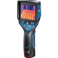
- GIS 1000 C Professional
- Montage
- Energieversorgung
- Product Description and Specifications
- Intended Use
- Product Features
- Declaration of Conformity C
- Assembly
- Power Supply
- Operation with Batteries
- (not for article number 3601 K83 370) (see figure A)
- Operation with Battery Pack (not for article number 3601 K83 370) (see figure B)
- Operation with Batteries (3 601 K83 370) (see figure C)
- Battery Status Indicator
- Operation
- Initial Operation
- Switching On and Off
- Setting the Zoom Level
- Illuminating the Measuring Surface
- Preparing for Measurement
- Setting the Emissivity Degree for Surface-temperature Measurements
- Measuring Surface for Surface-temperature Measurements
- Notes on the Measuring Conditions
- Measuring Functions
- Standard display screen
- Single Measurement
- Continuous Measurement (Tracking)
- Saving/Displaying/Sending Measuring Results
- Surface-temperature-mode
- Surface Temperature Alarm
- Contact Temperature Measurement
- Thermal-bridge-mode
- Dew Point Mode
- User Mode
- Data Transmission
- Data Transmission via USB Interface
- Data Transmission via Bluetooth®
- www.bosch-professional.com.
- "Main Menu"
- Navigating the "Main Menu"
- "Tool" Submenu
- Language:
- - Time/Date:
- Unit:
- Audio Signal:
- - Measuring Frame:
- Colour Scheme:
- - Shutdown Time:
- Light Duration:
- -Delete All Images:
- - Tool Information:
- Definitions
- Infrared heat radiation
- Emissivity Degree
- Thermal Bridge
- Relative Humidity
- Dew Point Temperature
- Maintenance and Service
- Maintenance and Cleaning
- After-sales Service and Application Service
- www.bosch-pt.com
- Great Britain
- Ireland
- Australia, New Zealand and Pacific Islands
- Republic of South Africa
- Customer service
- Gauteng - BSC Service Centre
- KZN - BSC Service Centre
- Western Cape - BSC Service Centre
- Bosch Headquarters
- Transport
- Disposal
- Only for EC countries:
- Battery packs/batteries:
- Li-ion:
- Français
- Humidity relative to the air
- Montaje
- Alimentación
- Montagem
- Montaggio
- Energievoorziening
- Montering
- Energiforsyning
- Navigation i, hovedmenuen
- Energiforsörjning
- Energitilforsel
- Asennus
- Energiahuolto
- Συναρμολόγηση
- Tpofoδoia
- Xpovoc anevpeyoinoic:
- Montaj
- Enerji saglama
- Montaz
- Zasilanie
- Montáž
- Napájení energii
- Provoz s bateriemi (nikoli u objednaciho cisla 3601 K83 370) (viz obr. A)
- Preprava
- Napájanie
- Összeszerelés
- Energiaellatas
- Available on the App Store
- Xpahenne
- TpaHcnpOpBbKa
- Yka3aHnno 6e30nacHOCTN
- OncanHe npoDyKta n ycny
- PnmeHne no Ha3haeHIO
- H306paXkeHHbIe COCTaBbIe qactN
- C6opka
- 3NeKtponHtAnHe
- 3Kcnnyataaunr ot 6aTaapeek (Kpome TObapHoro Homepa 3 601 K83 370) (cm. pnc. A)
- 3Kcnnyataaon OAKyMnTOpHoi6batape (Kpome TOBapHoro Homepa 3601 K83 370) (cm. pnc. B)
- 3Kcnnyataaonr ot 6aTaapeek (3601 K83 370) (cm.pnc.C)
- HdHKaTOp 3apJxKeHHOcTH
- Yka3aHnOTHoCHTenbHo ycNoBn H3MepeHHN
- PexnMbI n3MepeHH
- CtahapTha KapTHHka 3KpHa
- EHHHue H3MepenHe
- PpOdoJXHTeJIbHoe H3MepeHne
- CoxpaenHe/0To6paxeHne/OTnpaBnEnHe pe3ynbTaTOB H3MepeHHA
- PexHM TeTIOBOrO MoCTa
- PeknM ToQKn pOcbI
- PexHM nolb30BaTea
- IorchenTepMHOB
- Hnpaekpachoe TeNoBoe n3nyueHne
- Ko3ΦΦHnEHTn3nyeHnA
- TeTIOBOH MOCT
- OTHOCHTeBHaB BnAaXHoCTb BO3dya
- Touka pocibl
- TexobcnyxmbaHne n cepBnc
- TexobnyKbHaHne nOchctKa
- CepBnC n KOHCyNbTHpOBaHne Ha npEiMeT nCIOJIb3OBAHH npOdyKcHH
- ДлpernoHa: Pocchra, Белapycb, Ka3axctan, YkpanHa
- Pocchra
- Benapycb
- Tolbko dna ctpan-uehoB EC:
- Akkymytnopbl,6atapen:
- YkpaIHcbka
- Bka3iBkn 3 texhikn 6e3nekn
- MoHTax
- JKepeNo JKNBneHn
- Ekncnnyataia BID akymyntopho6taapei (kpim ToBapHoro Homepa 3601K83370) (mB. Man. B)
- EknpnyatauB iD 6atapeHok (3601K83370) (nVB.Man.C)
- IIndkaTop 3apdKeHocti
- BmipuBaIbHi FyHKcii
- Okpeme BmipioBaHHa
- Tpmbane BmmpioBaHHa
- 36epexehn/bo6paXeHHBipnpaBHeHHpe3yIbTaB BHmipIOBaHH
- PexHM Temnepatypn nobepxhi
- CnHnlaiaqia Tempeatypn nobepxhi
- Bmipobahn TemnepaTy KOHTAKTy
- - Yac/Data:
- -ODHHN4A:
- - 3ByKOBn CnHnA:
- BmipioBaIbHa paMka:
- - KonbopoBa cxema:
- - YacBMMKahHHa:
- Tpnbanictb niicbiuybaHHa:
- Bndaunntyci 306paXeHHa:
- - Ihfoopmaizipno BmipioBaIbHH IHCTpyMeHT:
- Texhue o6cnyroByBaHHiaounHn
- Cepbic Ta HadaHna KOHCyNbTaCii 0oDo BHKOpNCtAHn npOdyKcii
- YkpaHa
- TpaHcnpTyBaHHa
- Ytunizaia
- Jnne nKpaH EC:
- AkymnyTopn/6atapeienKn:
- JitieBO-ioHHI:
- Ka3akwa
- Ehimi nai danany Mep3iM
- Kb3METKeHeme NaaHaNHyBbHbH, KaTeiKTepi MeH icTeH WbIry ce6entepinH Ti3imi
- Uekri kyn 6enrinepi
- Kayinci3dk HycKaynapbl
- KohtaTtK TemnepaTypaHbI enwey
- Tepmo3nemEnTIH naDanaHy HcKaynbIFbIH OKbln opbIHaHbI3.
- Xbblbikkkenipnepi pexnmi
- Epy hykteci peknmi
- PaindanaHuybipeXnmi
- DepeKTePdiTacbImaIaNay
- USB ywblbfaapkblnbdepeKTeepiTacbImanay
- Bluetooth® apkblnbpekeTepdiTacbImanay
- Available on the
- App Store
- ,5ac mə3ip"
- Bac m3ipre" 0rii3
- - Bapnbik cypeTrepdi ewipy:
- KypbInfblTypanblaaknapaT:
- TepMHonorna TycinikTeMeenepi
- HΦpaKaBb3bl Xbblbnbik cayenehyi
- 3Mnccna dapekeci
- Xbinnbnikk epi
- CaIbIcTbIpMaIbl aya bInFaIdbIfbl
- Epy HKyTeciH TemnepaTypacbi
- TexHnKanblk Kytim XHe KbI3MeT
- KbI3MeT KcpCeTy XHe Ta3aNay
- TyTbIHyBbIFa Kbl3Met KOpCety XHe naiDaIaNy KeHecTepi
- Ka3aKctan
- TacbImaIay
- Kadere Kapaty
- Tek KaHa EO endepi yuin:
- Akkymytnatopnap/6atapennap:
- ΠΤΗ-ΝΟΗβΙΚ:
- Româna
- Instructiuni privind siguranta si protectia muncii
- Montare
- Mоntиранe
- 3axpaHbAHe
- Pa60Ta c 6bHKHOBeH 6aTePHN (IINCBA npn KaTALOKeH Homep 3 601 K83 370) (BHXTe CnR. A)
- Pa6ota c akymynaTopha 6aTePn8 (IINNCBa npn KaTANOKeH Homep 3 601 K83 370) (BHXTe fnr. B)
- Pa60Ta c 06nKHOBeHN 6aTePHN (3 601 K83 370) (BHXTe fHr. C)
- CBeTINHeH HnDnKaTOp 3a CTeNeHTa Ha 3apeDeHoCT Ha 6a- Tepnra
- Pa6ota c ypeda
- Pnyckahe B ekcnloaataua
- BknIOuBaHe n3KnIOuBaHe
- HactpoBaHeHaCTeNeHTaHa yBemueHne
- OcbetBaHe Ha H3MepBaHaTa IOBbpxHOCT
- IodrotOBKaHaH3MepBaHeTo
- HactpoBaeHa KoeΦnueHtA Ha n3bUbae 3a H3MepBaHe Ha NOBbpxHOCTHa TEMpepaTpa
- Yka3aHnna 3a OKoJIHnTe yCIOBn npn n3MePbAe
- PexmmHa n3MepBahe
- EHHHnHn H3MePbAHn
- HenpeKbchato n3MepBaHe
- 3anametraBaHe/naKa3BaHe/H3npaHaHe Ha pe3yntaTH OT n3MepBaHTo
- Pexmm n3MepBaHe Ha NOBbpxHocTha TemnepaTypa
- AnapMa 3a noBbpxHoctha temnepaTypa
- Kohtaktho H3MepBaHe Ha TemnepaTypa
- - Ilpoyetete H cna3BaIte yka3aHnraTa 3a non3BaHe Ha TepmoeIemEHa.
- PexHM OnpeDeneHa ToPnHHM MocToBe
- PexHM TemnepaTypa Ha opocBaHe
- Iotppe6HTeJckn peKHM
- PpehaheHa daHHN
- IpeHoc Ha daHHupe3 USB nHTeppeca
- IpehaeHa daHHuype3 Bluetooth
- 《Главно MeHIO》
- HabirhpaeB«TnaBHO MeHo
- Поммен «Ураз»
- -E3NK:
- -Mepha eHnHua:
- - 3ByKOB cHrHaI:
- -Измервашираамka:
- UBeTOba CXema:
- Bpeme 3a n3KnIOuBaHe:
- IpoobnxHTenHcT Ha CBeTeHe:
- H3tpBaHe Ha BCnKn CHmKn:
- - Hhopmaun3a ypega:
- OTHOCHTeHa BnaKHOCT Ha Bb3dYxa
- TemnepaotypaHaopocBahe
- PoiDbpxKaHe n cepBn3
- IopdbpxaHe n nouHCTBaHe
- CepBn3 n TexHnueckn CbBETn
- Po6epT BoW EOOD - BbIrapn
- TpaHcnpTnpaHe
- БракуВанe
- Cama 3a cTpaHn ot EC:
- Akymynatopn Hnn 06nkHObeHH 6aTeepn:
- Li-lon:
- MaKeDoHcKn
- Бe36eДнОСН НАПОМЕН
- OncnHa npOn3B0DoT mOkHocTa
- YnOtnpe6a co COoDBeTHa HameHa
- Hnyctpaunja Ha KOMnoHeHTN
- N3jaba 3a c0o6pa3HocT C
- MONTAXA
- HanojyBahe co eheprnja
- OcbetnyBaBe Ha MepHaT a NobpwnHa
- IoprotoBka 3a Mepebe
- IopecyBaBe Ha cTepeHOT Ha emncnja npn MepeBe Ha temepaTypata Ha NOBpHHN
- MepnФункци
- mO3HaKaHa MeHHTo
- EdupeHMOpebe
- MepeheHaBpemetpaebe
- 3auyByBaBe/npHKaKyaBaBe/HcnpaKaBe Ha n3MepeHnte pe3yntatn
- PexHM Ha temnepaTpya Ha nobpwnH
- Anapm 3a TemnepaTypaHa noBpuHHata
- Mepebe Ha KOHTaTHaTa TemnepaTypa
- - Пожнайто си вьимаBJte Ha ynatCTBTO 3a -уnotpe6a Ha tepMOeJEMENTOT.
- PexHM Ha TOnHHCKM MoCTOBH
- PexHM Ha Touka Ha pocebe
- Kopncnqupekm
- Ipehoc Ha noaToCu
- Ipehoc Ha noaatoqn peky USB-ntepcejc
- PpeHecyBaBe Ha noTaOnn ppeKy Bluetooth
- "Jnab.MEHN
- Habirnpajte do,ΓnaB.MeHH"
- Побмени „уразс"
- -Mepn paMKn:
- - ⅢeMaHa6oH:
- BpemeHaNckny.:
- BpeMeTp.HaCBet.:
- Брш.нст ecnkn:
- - Hhopm.3a ypeoT:
- CepBncha cnyk6a n coBeTH npN KopncTebe
- MaKeDoHnJa
- TpaHcnpr
- OCTpaHyBaBe
- Cama 3a 3emjn BO pamkn Ha EY
- Batepni:
- JTHym-jOHCKH:
- Srpski
- Uputstva o sigurnosti
- Montaža
- Oskrba z energijo
- Elektricno napajanje
- Rad s baterijama (ne za kataloški broj 3 601 K83 370) (vidjeti sliku A)
- Elektrobarosana
- Montavimas
- jglgao gao
- jIJI UlogJoo
- :labk1 Cg
- JlI 1
- wulalbawo
- 山
- Ig aiaJ Iog
- JusaiJusai
- oJgaaJI 1j
- aaiuui
- pLa oLg
- jglo lso
- abw 5 aJ
- jJU
- guiygbj
- piw is abai sls
- :Jgjogoljooj
- :Liwjoo
- :glaosdooJSLy
- :
- Uebl Jai
- USBJlaIgduwgyIeIbIJIaI
- piw 1slo s abai Jla
- abw llos
- abw [slo]
Brand : BOSCH
Model : GIS 1000 C Professional
Category : Camera