GML 20 Radio - Laser level BOSCH - Free user manual and instructions
Find the device manual for free GML 20 Radio BOSCH in PDF.
| Product type | Job site radio with audio player |
| Brand | Bosch |
| Model | GML 20 |
| Power supply | Mains 230/110 V or Li-ion battery 14.4/18 V (not included) |
| Backup batteries | 2 x 1.5 V LR06/AA |
| Weight | 10.2 kg (according to EPTA 01:2014) |
| Protection rating | IP54 (dust-tight and protected against water splashes) |
| Radio frequency range | FM: 87.5 - 108 MHz; AM: 531 - 1602 kHz |
| Amplifier power | 20 W (mains powered) |
| Compatible audio formats | MP3, WMA |
| Connectivity | 2 x AUX inputs (3.5 mm), LINE OUT (3.5 mm), USB port, SD/MMC slot, 12 V socket |
| Display | Yes, with time display |
| Equalizer | Presets JAZZ, ROCK, POP, CLASSICAL and manual adjustment (treble/bass) |
| Station memory | 20 FM stations, 10 AM stations |
| Operating temperature | 0 °C to 45 °C |
| Storage temperature | -20 °C to 50 °C |
| Maintenance | Clean with a dry cloth; entrust repairs to a Bosch-approved professional |
| Safety | Read warnings; do not expose to rain; use a residual current device (RCD) outdoors |
| Included accessories | AUX cable (depending on version), user manual |
| After-sales service | Contact Bosch France at 0811 360 122 or visit www.bosch-pt.fr |
Frequently Asked Questions - GML 20 Radio BOSCH
User questions about GML 20 Radio BOSCH
0 question about this device. Answer the ones you know or ask your own.
Ask a new question about this device
Download the instructions for your Laser level in PDF format for free! Find your manual GML 20 Radio - BOSCH and take your electronic device back in hand. On this page are published all the documents necessary for the use of your device. GML 20 Radio by BOSCH.
USER MANUAL GML 20 Radio BOSCH
OBI BUCI-1181-004. book Page 1 Tuesday, April 19, 2016 1:23 PM
Robert Bosch Power Tools GmbH
70538 Stu gart
GERMANY
www.bosch-pt.com
160992A2NE(2019.03)1/231

GML 20 Professional

BOSCH
on Original instructions
f Notice originale
es Manual original
pt Manual original
Read all safety warnings and all instructions, including the information
on the bottom side of the construction site radio. Failure to follow the warnings and instructions may result in electric shock, fire and/or serious injury.
Save all safety warnings and instructions for future reference.
The term "construction site radio" used in the safety notes, refers to mains-powered construction site radios (with mains cable) and to battery-operated construction site radios (without mains cable).
- Keep work area clean and well lit. Cluttered or dark areas invite accidents.
The plug of the construction site radio must match the outlet. Never modify the plug in any way. Do not use any adapter plugs with earthed (grounded) construction site radios. Unmodified plugs and matching outlets will reduce the risk of electric shock.
Do not misuse the cord to carry the construction site radio, hang it up, or for pulling the plug out of the outlet. Keep the cord away from heat, oil, sharp edges or moving parts. Damaged or entangled cords increase the risk of electric shock.
- Completely unwind the mains cable when operating the construction site radio via mains supply. Otherwise the mains cable can heat up.
Take care that the mains plug can be pulled at any time. The mains plug is the only possibility to disconnect the construction site radio from the mains supply.
When operating the construction site radio outdoors, only use extension cords suitable for outdoor use. Use of a cord suitable for outdoor use reduces the risk of electric shock.
When operating the construction site radio in damp environments is unavoidable, use a residual current device (RCD). The use of a residual current device (RCD) reduces the risk of electric shock.
Connect the construction site radio to a mains supply that is properly connected to earth. Socket and extension cord must have an operative protective conductor.

Do not expose the construction site radio to rain or wet conditions. Water entering a construction site radio will increase the risk of electric shock.
- Keep the construction site radio clean. Contamination may result in danger of electric shock.
Check the construction site radio, cord and plug each time before using. Do not use the construction site radio when defects are detected. Do not open the construction site radio yourself and have it repaired only by qualified personnel using original spare parts. Damaged construction site radios, cords and plugs increase the risk of electric shock.
This construction site radio is not intended for use by children and persons with physical, sensory or mental limitations or a lack of experience or knowledge. This construction site radio can be used by children aged 8 or older and by persons who have physical, sensory or mental limitations or a lack of experience or knowledge if a person responsible for their safety supervises them or has instructed them in the safe operation of the construction site radio and they understand the associated dangers. Otherwise, there is a danger of operating errors and injuries.
Supervise children during use, cleaning and maintenance. This will ensure that children do not play with the construction site radio.
Do not open the battery. Danger of short-circuiting.

Protect the battery against heat, e.g., against continuous intense sunlight, fire, water, and moisture. Danger of explosion.
When battery pack is not in use, keep it away from other metal objects like paper clips, coins, keys, nails, screws, or other small metal objects that can make a connection from one terminal to another.
Bosch Power Tools 1609 92A 2NE (19.4.16)


14 | English
Shorting the battery terminals together may cause burns or a fire.
Under abusive conditions, liquid may be ejected from the battery; avoid contact. If contact accidentally occurs, flush with water. If liquid contacts eyes, additionally seek medical help. Liquid ejected from the battery may cause irritations or burns.
In case of damage and improper use of the battery, vapours may be emitted. Ventilate the area and seek medical help in case of complaints. The vapours can irritate the respiratory system.
- Recharge only with the charger specified by the manufacturer. A charger that is suitable for one type of battery pack may create a risk of fire when used with another battery pack.
Only use the battery in conjunction with your construction site radio and/or a Bosch power tool. This is the only way to protect the battery against dangerous overload.
The battery can be damaged by pointed objects such as nails or screwdrivers or by force applied externally. An internal short circuit can occur and the battery can burn, smoke, explode or overheat.
Read and strictly observe the safety warnings and working instructions in the operating instructions of the tools that you connect to the construction site radio.
▶ Products sold in GB only: Your product is fitted with a BS 1363/A approved electric plug with internal fuse (ASTA approved to BS 1362).
If the plug is not suitable for your socket outlets, it should be cut off and an appropriate plug fitted in its place by an authorised customer service agent. The replacement plug should have the same fuse rating as the original plug. The severed plug must be disposed of to avoid a possible shock hazard and should never be inserted into a mains socket elsewhere.
Product Description and Specifications

Read all safety warnings and all instructions. Failure to follow the warnings and instructions may result in electric shock, fire and/or serious injury.
While reading the operating instructions, unfold the fold-out page with the illustration of the construction site radio and leave it open.
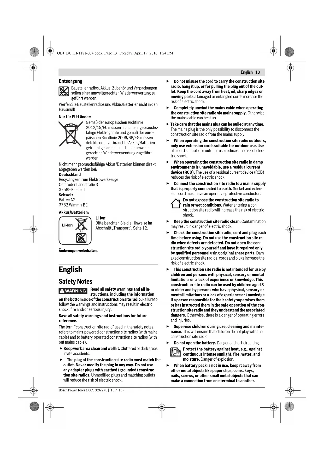
Product Features
The numbering of the product features refers to the illustration of the construction site radio on the graphics page.
1 Speaker
2 Carrying handle
3 Control lamp for AC supply (not for article number 3601 D29760)
4ACoutlet cover (notfor article number 3601D29760
5 AC socket outlet (not for article number 3601D29760)
6 Latch of back-up battery lid
7 Back-up battery lid
8 Locking latch of digital media bay flap
9 Digital media bay flap
10 Rod antenna
11 Battery port
12 Locking latch of battery lid
13 Battery lid
14 Battery pack*
15 "Equalizer" button
16“Memory”button
17 "Custom" button (for manual sound adjustment)
18 "Clock" button (for setting the time)
19 "Tune" adjustment knob (for tuning of stations)
20 Button for random playback/repeat
21"Seek+/>>] button
22 "Source" button (for selecting an audio source)
23 "I<-Seek" button
24 Play/pause button
25 Adjustment knob for volume level ("Volume") and sound ("Bass/Treb")
26 On/Off button for audio operation
27 Display
28 "AUX 1 IN" socket
29 12 V connection socket
30 "LINE OUT"socket
31 Fuse cap
32 Fuse for 12 V connection
33 USB port
34 SD/MMC slot
35 "AUX 2 IN" socket
36 Holder for external audio sources
*Accessories shown or described are not part of the standard delivery scope of the product. A complete overview of accessories can be found in our accessories program.
Display elements for audio operation
a Equalizer (sound-pre-set) indicator
b Changing treble -indicator
c Changing bass - indicator
d Indicator for volume, memory location for radio station and title (depends on the selected audio source)
e Station-memory reception indicator (for radio operation)
f Random playback indicator (for SD/MMC card or USB audio source)
g Repeat-current-track indicator for all tracks in the current folder/direction (for SD/MMC card or USB audio source)
h Repeat-current-track indicator (for SD/MMC card or D) USB audio source)
i Stereo indicator
j Indicator of radio frequency/Play duration of current track (depends on the selected audio source)
k Temperature warning
Battery inserted indicator
m Audio-source indicator
n Time indication display
Technical Data
| Construction Site Radio GML 20 | |
| Article number | 3601 D297.. |
| Back-up batteries | 2 x 1.5 V (LR06/AA) |
| Battery | V 14.4/18 |
| Weight according to EPTA-Procedure 01:2014 | kg 10.2 |
| Protection class | ± /I |
| Degree of protection | IP 54 (dust and splash water protect- ed) |
| Permitted ambient temperature | |
| -during charging | °C 0...+45 |
| -during operation* | °C 0...+45 |
| -during storage | °C -20...+50 |
| Recommended batteries | GBA 14,4 V ... |
| GBA 18 V ... | |
| Recommended chargers | AL 18.. |
| GAL 3680 | |
| Audio Operation/Radio | ||
| Operating voltage | ||
| - for mains operation | V | 230/110 |
| - for battery operation | V | 14.4/18 |
| Rated output of amplifier (for mains operation) | W | 20 |
| Reception range | ||
| - FM | MHz | 87.5-108 |
| - AM | kHz | 531-1602 |
Supported file formats* MP3,WMA
- Limited performance at temperatures <0 °C
** (for SD/MMC card or USB audio source)
Technical data determined with battery from delivery scope.
Assembly
Power Supply of the Construction Site Radio
The power supply of the construction site radio can take place via the mains supply or via a lithium ion battery inserted in the battery port 11. When the battery is used for power supply, only the functions audio operation and power supply of external devices via the integrated USB connection, are available.
Observe the mains voltage! For power supply via mains, the voltage of the power source must correspond with the data on the type plate of the construction site radio. Construction site radios marked with 230V can also be operated with 220V .
Battery Insertion/Removal (see figure A)
Note: Use of batteries not suitable for the construction site radio can lead to malfunctions of or cause damage to the construction site radio.
Disengage locking latch 12 of the battery lid ("Battery Bay") and fold out the battery lid 13.
Insert a battery into the battery port 11 in such a manner that the connections of the battery face against the connections in the battery port 11, and allow the battery to engage in the battery port.
As soon as a battery is inserted, the indication appears on the display. The indicator flashes when the battery is low.
When the battery is too warm or too cold for operation, the temperature warning indicator k on the display lights up. Wait until the battery has reached the allowable temperature range before putting the construction site radio into operation.
To remove the battery 14, press the release button on the battery and pull it out of the battery port 11.
After inserting or removing the battery, close the battery lid 13. Lock the battery lid by engaging the locking latch 12 in the housing and then pressing down.
Battery Charging
Use only the chargers listed in the technical data. Only these chargers are matched to the lithium-ion batteries permitted for use in your construction site radio.
Note: The battery supplied is partially charged. To ensure full capacity of the battery, completely charge the battery in the battery charger before using your power tool for the first time.
The lithium-ion battery can be charged at any time without reducing its service life. Interrupting the charging procedure does not damage the battery.
Inserting/Replacing the Back-up Battery (see figure A)
In order to store the time in the construction site radio, backup batteries have to be inserted. Using alkali-manganese batteries is recommended for this purpose.
Disengage locking latch 12 of the battery lid ("Battery Bay") and fold out the battery lid 13.
Remove the battery 14, if required.
To open the back-up battery lid 7, press on the latch 6 and re
move the back-up battery lid. Insert the back-up batteries. When inserting, pay attention to the correct polarity according to the representation on the inside of the back-up battery compartment.
Mount the back-up battery lid 7 again.
"REPLACE AA BATTERY WHEN UNIT NO LONGER KEeps CORRECT TIME": Replace the back-up batteries when the construction site radio no longer stores the time.
Always replace all batteries at the same time. Only use batteries from one brand and with the identical capacity.
- Remove the back-up batteries from the construction site radio when not using it for longer periods. When storing for longer periods, the back-up batteries can corrode and discharge themselves.


16|English
Operation
- Protect the construction site radio against moisture and direct sunlight.
Audio Operation (see figures B and C)
Switching Audio Operation On/Off
To switch on audio operation (radio and external playback devices), press the On/Off button 26. The display 27 goes on and the last set audio source after switching off is activated.
When the construction site radio is in the energy saving mode (see "Energy Saving Mode", Page 18), press the On/Off button 26 twice to switch on audio operation.
To switch off audio operation, press the On/Off button 26 again. The current audio source setting is stored.
To save energy, only switch the construction site radio on when using it.
Adjusting the Volume
To increase the volume, turn the "Volume" 25 adjustment knob clockwise; to reduce the volume, turn the adjustment knob anticlockwise. The volume setting (value between 0 and 20) appears for a few seconds in indicator d on the display.
Before adjusting or changing a radio station, set the volume to a lower setting; before starting an external audio source, set the volume to medium.
Adjusting the Sound
An equalizer is integrated in the construction site radio for optimal sound reproduction.
The treble and bass setting can be manually changed or sound pre-sets for various music styles can be used. The following pre-programmed settings are available: "JAZZ", "ROCK",
"POP" and "CLASSICAL" apart from the individually programmable setting "CUSTOM".
To select one of the stored sound pre-sets, press the "Equalizer" button 15 until the desired setting is indicated in indicator a on the display.
Changing the "CUSTOM" Setting:
- Press the "Custom" button 17 once. The "BAS" indicator c flashes on the display and the stored bass level flashes in indicator d.
- Set the desired bass level (value between 0 and 10). To increase the bass level, turn the "Bass/Treb" adjustment knob 25 clockwise; to reduce the bass level, turn the adjustment knob anticlockwise.
To store the set bass level, press the "Custom" button 17 a second time. The "TRE" indicator b flashes in the display for the following treble adjustment, and the stored treble value flashes in indicator d. - Set the desired treble level (value between 0 and 10). To increase the treble level, turn the "Bass/Treb" adjustment knob 25 clockwise; to reduce the treble level, turn the adjustment knob anticlockwise.
- To store the set treble level, press the "Custom" button 17 a third time.
Selecting an Audio Source
To select an audio source, press the "Source" button 22 until indicator m for the desired internal audio source (see "Setting/Storing Radio Stations", page 16) or external audio source (see "Connecting External Audio Sources", page 17) appears in the display:
-FM:FM radio,
-“AM”: AM radio,
"AUX 1": External audio source (e.g. CD player) via the 3.5 mm socket 28 on the side,
"AUX 2": External audio source (e.g. MP3 player) via the 3.5mm socket 35 in the digital media bay,
- "USB": External audio source (e.g. USB stick) via the USB port 33,
- "SD": External audio source (SD/MMC card) via the SD/MMC slot 34.
Setting the Rod Antenna
The construction site radio is provided with a mounted rod antenna 10. For radio operation, point the rod antenna toward the direction that enables the best reception.
When the reception is insufficient, position the construction site radio at a different location that enables better reception.
Note: When operating the construction site radio in the direct vicinity of radio-communication equipment or radio transceivers, or other electronic equipment, the radio reception can be subject to interference.
If the rod antenna 10 should become loose, tighten it directly at the housing by turning in clockwise direction.
Setting/Storing Radio Stations
Press the "Source" button 22 until "FM" is indicated for the ultra-short wave reception range or "AM" for the medium wave reception range in display element m.
To set a certain radio frequency, turn the "Tune" adjustment knob 19 clockwise to increase the frequency, and anticlockwise to decrease it. During setting, the frequency is indicated in display section n, then in j.
To scan for radio stations with a high signal strength, press and briefly hold the "Seek" button 23 to scan down and the "Seek +" button 21 to scan up the frequency scale. The frequency of the found radio station is briefly indicated in display n and then in j.
When the reception of a suitable signal is sufficiently strong, the construction site radio automatically switches to stereo reception. The indicator for stereo reception i appears on the display.
To store a set station, press the "Memory" button 16. The "PRESET" indicator e flashes in the display and the number of the last preset in d. To select a preset, press the "-Seek" button 23 to scan down and the "Seek+" button 21 to scan up, until the desired preset is displayed in indicator d. Press the memory button 16 again to store the set station as the selected preset. The indicators e and d no longer flash.
A total of 20 FM and 10 AM stations can be preset. Please note that an already occupied preset is overwritten when a new radio station is assigned to it.

For playback of a preset station, briefly press the "Seek" button 23 to scan down or the "Seek +" button 21 to scan up, until the desired preset is displayed in indicator d and "PRESET" is displayed in e.
Connecting External Audio Sources (see figure C)
Apart from the integrated radio, various external audio sources can be played.
AUX-In connection 1: The AUX-In connection 1 is particularly suitable for audio sources to be placed outside of the digital media bay (e.g. a CD player). Remove the protective cap of the "AUX 1 IN" socket 28 and insert the 3.5mm plug of the provided or of another matching AUX cable into the socket.
Connect the AUX cable to an appropriate audio source. After removing the AUX cable, reattach the protective cap of the "AUX 1 IN" socket 28 to protect against dirt/debris.
For external audio sources via the following connections, open locking latch 8 and open lid 9 of the "Digital Media Bay".
- SD/MMC connection: Insert a SD or MMC card into the SD/MMC slot 34. The labelling of the card must face toward the fuse cap 31. Playback of the card can be started as soon as the track number as well as the number of available tracks on the card are displayed in indicator d. To remove the card, briefly press on the card, which is then ejected.
- USB connection: Insert a USB stick (or the USB plug of an appropriate audio source) into USB port 33. Playback of the USB stick can be started as soon as the track number as well as the number of available tracks on the stick are displayed in indicator d. To remove the USB stick, pull it out of the USB port.
- AUX-In connection 2: AUX-In connection 2 is particularly suitable for audio sources that can be placed inside of the digital media bay (e.g. a MP3 player). Insert the 3.5mm plug of the provided AUX cable into the "AUX 2 IN" socket 35. Connect the AUX cable to an appropriate audio source.
When small enough, the connected external audio source can be fastened into the digital media bay using the Velcro strap of the holder 36.
After connecting the external audio source, close the Media/connections flap 9 if possible, to protect against damage and debris.
For playback of the connected audio source, press the "Source" button 22 until the indicator m for the desired audio source appears on the display.
Controlling External Audio Sources
For audio sources connected via the SD/MMC slot 34 or the USB port 33, playback can be controlled via the construction site radio. The number of the selected track is displayed at the left of indicator d and the number of available tracks on the right.
Play/Pause:
To start playback, press the play/pause button 24. The playing time of the current track is displayed in indicator j.
- To interrupt or continue the playback, press the play/pause button 24 again. The current playing time flashes in indicator j.
Selecting Tracks:
To select a track, press the -Seek button 23 to scan down or the Seek + button 21 to scan up, until the number of the desired track is displayed on indicator d.
-To start playback, press the play/pause button 24.
Random Playback/Repeat:
- For random playback of all tracks on the card or the USB stick, press the random playback/repeat button 20 once. The indicator f appears on the display.
- To repeat all tracks in the current folder/direction, press the random playback/repeat button 20 a second time. The indicator g appears on the display.
Note: Only in this function, the number of the current folder/direction on the card or USB stick will appear on the right-hand side of indicator d. To change the folder/direction, you have to return to the normal playback first and select a track from the desired folder/direction.
- To repeat only the current track, press the random playback/repeat button 20 a third time. The indicator h appears on the display.
- To return to normal playback mode, press the random playback/repeat button 20 a fourth time, so that none of the indicators f, g or h appear on the display.
- To start playback, press the play/pause button 24.
Connecting External Audio Playback (see figure C)
The current audio signal of the construction site radio can also be transferred to other playback devices (e.g. amplifier and speakers).
Remove the protective cap of the "LINE OUT" socket 30 and insert the 3.5mm plug of a matching AUX cable into the socket. Connect an appropriate playback device to the AUX cable. After removing the AUX cable, reattach the protective cap of the "LINE OUT" socket 30 to protect against dirt/debris.
Power Supply of External Devices
The power supply of external devices via the 12 V and the AC connection is possible only when the construction site radio is connected to mains, and not via the inserted battery.
When the construction site radio is connected to the mains supply, this is confirmed by the lit green control lamp 3.
USB Connection
With the USB connection, it is possible to operate and charge most devices whose power supply is possible via USB (e.g., various mobile phones).
Disengage locking latch 8 and open the digital media bay flap 9. Connect the USB plug of the external device to the USB port 33 of the construction site radio. To start the charging procedure, the external device must possibly also be selected as the audio source on the construction site radio.
12 V Connection (see figure C)
With the 12 V connection socket, you can operate an external electrical device with a 12 V plug and a max. current consumption of 1 A.
Remove the protective cap of the 12 V connection socket 29. Insert the plug of the external electrical device into the 12 V socket outlet.


18|English
The 12 V connection socket is protected by a fuse 32. When no voltage is given after connecting an external device, disengage locking latch 8 and open the digital media bay flap 9. Un-screw the fuse cap 31 and check if the inserted fuse 32 has blown. If the fuse has blown, insert a new fine-wire fuse (5 x 20 mm, 250 V max. voltage, 1 A rated current and quick-acting tripping characteristic). Screw on and tighten fuse cap 31 again.
Note: Use only 1 A fuses for a max. voltage of 250V ("250V 1A FUSE FOR 12V OUTLET"). When using other fuses, the construction site radio can become damaged.
The 12 V connection is also protected with an internal thermal fuse, which is blown/actuated when overheated. The fuse is automatically reset after the construction site radio has cooled down.
After removing the external plug, reattach the protective cap of the 12 V socket outlet 29 to protect against dirt/debris.
AC Connection ("Power Outlets") (not for article number 3601 D29 760)
Further external electrical devices/tools can be operated via the AC outlets. The socket outlets can vary in consideration of country-specific standards.
The total maximum permitted current consumption of all connected electrical devices/tools must not exceed the value in the following table (also see the labeling on the housing under the outlet cover 4):
Article number Total max. current consumption (in A)
3601D2970015
3601D297309
3601D2977012
3601D297W015
3601D297X09
Open one of the AC outlet covers 4 and insert the plug of an external electrical device into a socket outlet 5 of the construction site radio.
Time Indication
The construction site radio is equipped with a time indication with separate power supply. When back-up batteries with sufficient capacity are inserted in the back-up battery compartment (see "Inserting/Replacing the Back-up Battery", page 15), the time can be stored even when the construction site radio is disconnected from the AC power supply or the battery.
Setting the Time
- To set the time, press and hold the "Clock" button 18 until the hours indication flashes in the time indication display n.
- Press the "Seek +" button 21 or the "-Seek" button 23 until the correct hour setting is indicated.
- Press the "Clock" button again, so that the minutes indication flashes in the time indication display n.
- Press the "Seek +" button 21 or the "-Seek" button 23 until the correct minute setting is indicated.
- Press the "Clock" button a third time to store the time setting.
Energy Saving Mode
To save energy, you can switch the time indication in display 27 off.
For this, press and hold the On/Off button 26 when switching off audio operation (see "Switching Audio Operation On/Off", page 16), until there is no indication on the display.
To switch the time indication on again, press the On/Off button 26 once.
Working Advice
Recommendations for Optimal Handling of the Battery
Protect the battery against moisture and water.
Store the battery only within a temperature range between -20^ and 50^ . As an example, do not leave the battery in the car in summer.
A significantly reduced working period after charging indicates that the battery is used and must be replaced.
Observe the notes for disposal.
Troubleshooting - Causes and Corrective Measures
Cause Corrective Measure
Construction site radio inoperative
| No power supply Properly insert mains plug or battery (completely) | |
| Construction site radio too warm or too cold | Wait until the construction site radio has reached operating temperature |
Construction site radio inoperative on AC power supply
| Mains plug or cord defective Check mains plug and cable and have repaired as required |
Construction site radio inoperative on DC power supply
| Battery contacts contaminated | Clean the battery contacts (e.g. by inserting and remov- ing the battery several times) or replace the battery |
Battery pack defective Replace the battery
| Battery too warm or too cold (temperature warning indicator k lit) | Wait until the battery has reached operating tempera-ture |
Power supply to external devices inoperative
| Mains plug not plugged-in Plug mains plug in (completely) |
12 V power supply inoperative
| No fuse 32 inserted | Insert fuse 32 |
| Fuse 32 blown | Replace fuse 32 |
| Internal thermal fuse blown/actuated | Remove external device and allow construction site radio to cool down |
Cause Corrective Measure
Construction site radio suddenly inoperative
Mains plug or battery not properly or completely plugged in Plug in mains plug or battery properly or completely properly or completely
Software error To reset the software, pull the mains plug and remove the battery; wait 30 seconds, then insert mains plug and battery again
Bad radio reception
Interference from other devices or insufficient set-up location Position the construction site radio at another location with better reception or with greater clearance to other electronic devices or socket outlets.
Time indication faulty
Back-up batteries of clock Replace back-up batteries empty
Back-up batteries incorrectly Insert back-up batteries inserted (wrong polarity) correctly
When the corrective measures do not eliminate an error, please contact an authorised service agent for Bosch power tools.
Maintenance and Service
Maintenance and Cleaning
The mains cable is provided with a special safety connection and may only be replaced by an authorised service agent for Bosch power tools.
After-sales Service and Application Service
Our after-sales service responds to your questions concerning maintenance and repair of your product as well as spare parts. Exploded views and information on spare parts can also be found under:
www.bosch-pt.com
Bosch's application service team will gladly answer questions concerning our products and their accessories.
In all correspondence and spare parts orders, please always include the 10-digit article number given on the type plate of the construction site radio.
Great Britain
Robert Bosch Ltd. (B.S.C.)
P.O.Box 98
Broadwater Park
North Orbital Road
Denham
Uxbridge
UB95HJ
At www.bosch-pt.co.uk you can order spare parts or arrange the collection of a product in need of servicing or repair.
Tel. Service: (0344) 7360109
E-Mail: boschservicecentre@bosch.com
Ireland
Origo Ltd.
Unit 23 Magna Drive
Magna Business Park
City West
Dublin 24
Tel. Service: (01) 4666700
Fax: (01) 4666888
Australia, New Zealand and Pacific Islands
Robert Bosch Australia Pty. Ltd.
Power Tools
Locked Bag 66
Clayton South VIC 3169
Customer Contact Center
Inside Australia:
Phone: (01300) 307044
Fax: (01300) 307045
Inside New Zealand:
Phone: (0800) 543353
Fax: (0800) 428570
Outside AU and NZ:
Phone: +61 3 95415555
www.bosch.com.au
Republic of South Africa
Customer service
Hotline: (011) 6519600
Gauteng - BSC Service Centre
35 Roper Street, New Centre
Johannesburg
Tel.: (011) 4939375
Fax: (011) 4930126
E-Mail: bsctools@icon.co.za
KZN - BSC Service Centre
Unit E, Almar Centre
143 Crompton Street
Pinetown
Tel.: (031) 7012120
Fax: (031) 7012446
E-Mail: bsc.dur@za.bosch.com
Western Cape - BSC Service Centre
Democracy Way, Prosperity Park
Milnerton
Tel.: (021) 5512577
Fax: (021) 5513223
E-Mail: bsc@zsd.co.za
Bosch Headquarters
Midrand, Gauteng
Tel.: (011) 6519600
Fax: (011) 6519880
E-Mail: rbsa-hq.pts@za.bosch.com


20 | Français
Transport
The contained lithium-ion batteries are subject to the Dangerous Goods Legislation requirements. The user can transport the batteries by road without further requirements.
When being transported by third parties (e.g.: air transport or forwarding agency), special requirements on packaging and labelling must be observed. For preparation of the item being shipped, consulting an expert for hazardous material is required.
Dispatch batteries only when the housing is undamaged. Tape or mask off open contacts and pack up the battery in such a manner that it cannot move around in the packaging. Please also observe possibly more detailed national regulations.
Disposal

Construction site radios, battery packs, accessories and packaging should be sorted for environmental-friendlyly recycling.
Do not dispose of construction site radios and battery packs/batteries into household waste!
Only for EC countries:
According to the European Guideline 2012/19/EU, electrical devices/tools that are no longer usable, and according to the European Guideline 2006/66/EC, defective or used battery packs/batteries, must be collected separately and disposed of in an environmentally correct manner.
Batteries no longer suitable for use can be directly returned at:
Great Britain
Robert Bosch Ltd. (B.S.C.)
P.O.Box 98
Broadwater Park
North Orbital Road
Denham
Uxbridge
UB95HJ
At www.bosch-pt.co.uk you can order spare parts or arrange the collection of a product in need of servicing or repair.
Tel. Service: (0344) 7360109
E-Mail: boschservicecentre@bosch.com
Battery packs/batteries:
Li-ion:
Please observe the instructions in section "Transport", page 20.
Subject to change without notice.
Français
32Fusible raccord 12 V
33 Douille USB
Raccord 12 V (voir figure C)
Robert Bosch (France) S.A.S.
Sous reserve de modifications.

28|Espanol
Espanol
A工程技术 of the Puerto.
A先进技术 of the Puerto.
A technology of the Puerto.
A technology of the Puerto.
A technology of the Puerto.
A technology of the Puerto.
A technology of the Puerto.
Bosch Service Center
Telegrafvej 3
2750 Ballerup
Pá www.bosch-pt.dk kander online bestilles reservedeleller oprettes en reparations ordre.
TIf. Service Center: 44898855
Fax:44898755
E-Mail: vaerktoej@dk.bosch.com
Transport
8 Lassparr for mediafackets lock
9 Mediafackets lock
10 Stavantenn
11 Batterischakt
12 Lassparr for batterischaktets lock
13 Batterifackets lock
14 Batteri
19 Ratt for sandarinstalling "Tune"
26 Pa-Av-knapp for Ijud
27 Display
28"AUX 1 IN"-kontaktdon
29 12 V-anslutningskontakt
30 "LINE OUT"-kontaktdon
31 Lock for sakring
32 Sakring for 12 V-anslutning
33 USB-kontaktdon
-FM":Radio via UKV,
- "AM": Radio via MV,
Bosch Service Center
Telegrafvej 3
2750 Ballerup
Danmark
Tel.: (08) 7501820 (inom Sverige)
Fax: (011) 187691
70|Norsk
Transport
Endast for EU-lander:
Euvtnpnon kal Service
Suvtnpnoan kalkaogapiaooc
To nalektpko kaiwdo evai eonlauevo me pa edikn ouvdean aopaaieac kai npenei va avtkaotatai anokleotika ano eva eouaoobotnevo katantna Service Tc Bosch.
Service kalapoxn oupouawxponc
To Service anavrt otic cwpntaoic oac oxytka me tny eniokeun kal n ouvtponan tou npoiovoc oac kaowc yia ta kataaann aavtaaaktka:
www.bosch-pt.com
H ouda napoxic oubouawv nC Bosch anavr euxapiotoc icepwntnoeic oac oxetikae ta npoiovta mac kai avtalakTkia Touc.
OTAVZntate diaaaqtnikc nnpoopopie cKaowkaiotavnapayyevete avtalakrtika npenei va aapepete onwa6hnoto
10nphi apiou eupntiou nou avaypafetai otnv ivakiokaatakeaonr Tou pabiopwov okoobov.
EAAa6a
Robert Bosch A.E.
Epxia37
19400Kopwni-Athya
Tnλ.: 2105701258
Φaξ:2105701283
www.bosch.com
www.bosch-pt.gr
ABZ Service A.E.
Tnλ.: 2105701380
QaE:2105701607
Meraopu
Opiexoeve matapeicovtwvliouunokvatotanat hoeic twv emikivuvw ayaw. Omuataie mnpouvaetapeoov obikoc an to xpntxupic aauoc opouc.
OraV, oUWC, OI matapeic anootellovrAIO TpTouc (N.x. aePonopoiKw nE eTaia petaopow) npTei va npouvTuai dApopeC 6iaitepe c anatnoe iY aTn ouokeuia kai tn onuavon. EoW npTei, kata nTv npoetouaia tou uno anooToAn TepaXou, va qntnBei onoobnote kai n oumbouh evoc etikou yia enkivduva ayaa.
Na anoatele TIC mntapiec mvo otav to nepiAma evai aikto. Na kollate TIC yuvc enapec me kollnki Ka va ouakeucetey nna tnapia kata TetoTpno, oote autn va uny couvietaa
Tapaakaloupe va lauabavete enionc, unoyn oac kai tuxov nio auotnpes eovkeic diataleic.
Anoupon

Ta pabiopwa oikobouw, o jnatapie, ta eApntjma-ta kai ouakeuaoei npenei va avakukawovtai pe Tpono qikko npoc to nepiaalov.
Mny teraete ra pabiopovva oikobopov kai tic umatapiec ota amopplmuata tou ontiou oc!
Movi yia xwpec tnc EE:
Tnpoue to dikaiwa aalayov.
Türkce
Güvenlik Talimatu
4UYARI
Calma/calmayi kesme:
Calma islemini baslatmak icin calma/ara verme tusuna 24 basin. Guncel basligin calma suresi gostergedj gozukur.
- Calma islemini kesmek veya surdurmek icin yeniden calma/ara verme tusuna 24 basin. Guncel calma suresi gosto tergede j gozukur.
Bashk seçimi:
Bosch San. ve Tic. A.S.
Ahi Evran Cad. No:1 Kat:22
Polaris Plaza
80670 Maslak/Istanbul
Bosch Uzman Ekibi +90 (0212) 367 18 88
Isiklar LTD.STI.
Kizilay Cad. No: 16/C Seyhan
Adana
Tel.: 0322 3599710
Tel.: 0322 3591379
Robert Bosch Sp. z o.o.
Data n3rOToBnEH yKa3aHa Ha Kopnyce n3denn.
KoHTaKTHa HnΦOpMaunr OTHOCHTeNbHO HmNtOpea CoepKHTcRa Ha yNaKOBKe.
Cpok cnyy6bln3denn
Cpok cnky6bI n3dennncoctabnre7 net. He pekomeHnyetcK kcnnyataun no ncteehnn 5 net xpaehnna C daTbI n3roTOBNEHn 6e3 npedbapntelho npobepkn (aTy n3rTOBNEHn CM. Ha 3TNKETke).
IpeuehB KpHTmueckHX OTka3OB H OwH6OuHbIe DeiCTBnepcohana Hnn Nnonb3OBaTeJIa
-HeHCIOB3OBAbC NOBpeKdEHHo pyKOaTkoHnIOBpeKdEHHbIM 3aUHTbIM KOxYXOM
-HeHCIOJIb3OBAbI pH IOBnEHIN DbIMa HENOCpeCTBeHHO Ⅲ Kopnyca H3dEINIA
-HeHCIOJIb3OBAbTcIpe6HTbIM HIN OOrJIeHHbIM 3JIeKTPnueCKHM KaBemEM
-HeHCIOB3OBaTbHaOTKpblTomIPOCTpaHCTBe BO BpeMdoJDA(BpacnblnEmoBoe)
-He BKNHouaTb npn nonaHaHH BOBbl KOpnyC
-HeNCNoB30BaTbPnCNbHOMNCKpeHHN
-HeHCnObl30BaTbPnNIOBnEHnCNbHOHnBpaun
Kpntepnn npedeBbix coctoHH
- nepetepHnnnoBpeJdEh 3JeKtpnueckn KaebIb
- noBpeKdEN KOpNc H3eINH
TnH n nepnouHoctb texHueckoro 06cnyxHBaHHN
PekomeHcyETcOuHCTnTBHHCTpyMeHTOTbIINNocNeKaXdoT OHCNOB3OBAHNA.
XpahHeHne
-Heo6xOIMXpaHHTbBCyXOMMeCTe
HeoXOJMO XpaHnB BdAnOTNCTOUYHKOB NOBbIeHHbIX TEMpePty N BO3deNCTBnCOnHehBXIyuei
- npn xpaHEn Hne6xOaMn 136eRaTpe3KOro nepenada TempeaTp
-xpaheHHe 6e3 ynaKOBKn He donyckaetc
- noDpObHbIe Tpe6oBaHnK yCIOBnM XpaHeHHc MOrTpHte BTOCT 15150 (yCNOBne 1)
TpaHcnpToPbOka
KaTeROpNueCKn He DonyckaTcnaDHe NJIIObIe MExaHNeCckne Bo3dEChTBnHa YpAkoBky PnP TpaHcNoptIpOBKe
- npn pa3rpy3ke/nporpy3ke He donyckaetc HcnoIb30BaHHe IIO6oOBuDaTeXHHKn,pa6OtaUoSeH NO npHunny3aKMa yNaKOBKN
- noDpO6HbIe Tpe6oBaHnK yCIOBnAM TpaHCnOpTnPOBKn CMOTPHTBFOCT15150(YcNOBHe5)
Yka3aHnno 6e3onachoctn
A PEPENPPEXDEHME
IpoountaTe BCE yka3aHHN IO TEXHnke 6e3ona
CHOCTN, a TAKKHe HnOpMaHIO B HnXHe YAcTH My3bl KaIbHorO CEHTPa DnA CTpontEnbHbIX NIOUADOK. HrHopPOBaHne Yka3aHm No TEXHKe 6eONaCHoCTn IN HcTpyKuM MoKe I pNBecTn K3eKTPueckOMy ydApY, NOkApY n/nn TaJKeBIM TpaBMam.
CoxpaHnIe BCE HNCTpyKuHH No 6e3oNaChocTH n yKa3aHHnI dI aJIbHeHero NOnb3OBAHH.
IIOHNCN0B3yEmbIMBykazaaHnXnTOxEHnke63oNaCHOCTNIHOHTHEM My3bikalnbHbIy CEHTpINCTPONTeNBbIX NIOOAKMIEOTCBBHNYKAKMy3bikalnbHbIyeCEHTpBIINCTPONTeNBbIX NIOUaOK,pa6oTAIOUneOTcETNIHTAHNO(COHNHYPOMNITAHNA),TAKHMy3bikalnbHbIEeHTpBIINCTPONTeNBbIX NIOUaOK,p6oTAIOUneOTAKKYMnTOpHBix 6atapei (6e3uhypaNHTAHNA).
CoepKHTpepaOooMeTcBnHCToHxopoOocBeHueHHbIM.BecnpaOKmHHeOCBeHHeIyAcTKn pa6oero MeTaMOrT npVBcTn K HeCuaCTbIM CnyaAM.
WtencbnaBnka My3bKaIbHoro eHTpa DnCTpOntbHbIX nloaAdOK DoNkHa NoDxOaNTb K po3eTke. Hn B KOem cnyae He N3MeHne TtencbHyIO Bnky. He BKIOuayTe My3bKaIbHbIe CEHTpbI DnCTpOntbHbIX nloaApok, MeIOUe 3auTHoe 3aEmeHne, Pepe3 aanTepbI. HeN3MeHeHHble tteCseBbIe BNKNi IOxOaJHne WtencbHbIe po3ETKn CHNKAOT pNCK npaaKHeHN3NEKTPTOKOM.
He donyckaetra hcnob30aBt Hhyp He no Ha3haeHHo, HanpHmep, nna nepenocn nnnoDBceK My3blKaIbHoro ceHTpa dna cTPOTeNbHbX IIOuaDOKnn DnBBITINBAHNBA BNKN N3 WTeNCEbHO pO3ETKn.3aUHauTe CeTEBoH hHyP OT BO3eHCTBN BcIOKOI Tempeatpyb, Macei, OCTpbIX KpOMK HnNOBbHXHbX qACTe 3NEkTPOHCTPyMeHa. NOpeKDeHbNn HnCNYAHHbN HWyp NOBbIaet PnCK npApaKeHHa 3NEkTPOueCKHM TOKOM.
PnH3KcNpyatauMy3bikanbHoro ceHTpa dtnCTponTeNbHbIX NIOUaOk OT CeTH NHTAHN NOHOCBIO paKpyuBaIe CeTEBOW hyp. Hauye shyHp MoKet Ha- rpeTcbra.
CneHte 3a TEM, qTo6bI wTeNcB MoXHo 6bIIO BIO 60 MoM OMeHT BbITauNTb H3 po3eTKn. OTKIOueHne paINOpPnEMHnka IaI cPoTHeBbIX PNOUaOk OT cETn BO3MOXHO TOJIbKO pI IN NOMOUs WTeNCEIA.
Pnpa60ax My3bikalhBhim cHTpOM dIcTPOHTeNbHbIX NIOUdoK NOO tKpbITbIM He6OM HCNOB3yTe TOnbKO yDHHNTEN, pa3peeHHBe IIN pa6oHa CBexem Bo3dyxe. HcNoB3OBaHHe yDHHNTEN, paccuTaHHoro Ha pa6oTbHa yInue, cHnKaet Pnck npapXeHHN 3NEKTPNueCKM TOKOM.
128|Pysckn
EcnHcnoB3ObaHHe My3bIaKbHOro cHTpaDnCTpoHTeNbBbIX NIOUaDOK BO BIAxHOI CpeDe HEN36ExHO,HCNOB3yTe ABTomAT 3aunTHORO OTKNIOHEn. NOB3OBAHne ABTOMaT 3aUNTHORO OTKNIOHEn yMeHb-10aET PnCK NopaxEHN 3JIeKTpueckHM TOKOM.
BknouaTe My3bikanbHbI ΚeHTpI dCTPOTeNbHbIX nOuaOK B 3aEmLeHHyU HApEkaHm O6pa30m cTb. B po3eKu yDnHInTe neJxKe H6bTb NcnpabHbI 3aunTHbI npoBOD.

3aunuante My3bikalhbln chtp nclctponTeIbHbIX IIOOaOK OT DOXKn Bnarn. IpOnHKOBHeHNE BOIBy BHyTpB My3bikalbHO rEHTpa dIcTPOnteHbIX IIIOUaDKIOBbIaETPNC NopaeHna 3JIeKTPueckm TKOM.
DepxHTe My3bIaKbHbI ueHtp dIg CTpOHTeNbHbIX nnoaDOK B uHCTOTE. Pn3 aRpa3HeHH np6oopa BO3HN KaET ONaCHOCTb IopaeHH 3NEkTPOTOKOM.
Pepa KaKdbm HcNOb3oBaHem npOBepnTe My3bl KaNbHbI cHTp dTcPOnteNbHbIX NIOUAdOK,WHyp H wTencBHyO BnKy. He hcnOb3yIte My3bKaNbHbI cHTp dTcPOnteNbHbIX NIOUAdOK,ecn BbI o6hApYxHN NOBpeXeHHa. He BCKpbBaTe My3bKaNbHbI cHTp dTcPOnteNbHbIX NIOUAdOK CaMOCToTeNbHO, eo PEmOH paPeWaeTcB bINONHtB ToNko KBaHNΦHnPOBaHHOMy nepcoHany nToBko C HcNOb3oBAHem opHHaHbIX 3AnactE. IOBpeXeHHbIE My3bl KaNbHbI cHTp dTcPOnteNbHbIX NIOUAdOK,WHyp HwTencBHe BnIK NOBIIaOT pckn OpaKeHHa 3NeKTPnuCeKM TOKOM.
3TOT My3bikabhbln cHTpIINCTPONTbHbIX INOaDOK He npedha3HaueH dN IHCNOB3OBAHNA DeTBM H NlUAMC O rpaHHueHbIMN FHN3NuECKHM, CEHCOPHBIM Nm yMCTBEHbIMN CNOcO6HOCTAM NnC HEDoCTA TOHBM ONbITOM N 3HaHNM. NOnb3OBaTcB 3TNM MY3bIKAbHbIM NcETPOM Dn CTPONTbHbIX INOuaDOK B BO3PACTe 8 nT n CTAPHe NnUaM C ORPAHHueHHbIMN FHN3NuECKHM, CEHCOPHBIM NnY mCTBEHbIMN CNOcO6HOCTAM NnC HEDoCTaTOHbIM NtBIOM N 3HaHNR M pa3peWaeTcTobKIO NOI pncmOTPM OTBETCTBEHORO 3aHX 6e3ONaCHOCTb NnUeN ECNI OH PPOWNN HNCTpykTAX HA npdMet HndexKHO rcoNb3OBAHN My3bIKAbHbO eHTpA dNCTPONTbHbIX INOuaDOK H NOHMAOT, KAKHE ONACHOCTH HxCODTOT HERO. IVaue CyuectBYet ONaCHOCTb HEPaBnIBHO rCNOB3OBAHN NnI NOyueHr TpaBM.
PnHcMatpHbAte 3a DetbMn BO Bpemn noB3oBaHna, npn BbyIOIneHHN ONUCTKN NTexO6CnyXHBHa. 3THM BBy npedOTbPaTHe Hpy DeTe C My3bKaJIbHbIM CEHTPOM DnA CTPOINNOJADOK.
He BcKpbIbAIte aKKyMnyTOp. Ipn 3ToM BO3HKnAe TOna-CHOCTb KOPOTKOrO 3aMbIKAHnA.

3aunuanteakymyntophyo6atapeoOT BbICOKX TEMnepaTy,p, HAp., OTdHNTenbHoro HArpeBaHHHa CONHe,OTOrH,BOBbHbarn. CyueCTByeTOnacHOCTbBpIbA.
3aunuatahe Hncnnonb3yembl aKKymyHTopOT KaHnce npcknxCKpenOK,MOHeT,KIOueH,1BO3eB,BHTOB Hdpyrnx MaIeHbKHX METALINUeCKNX PpeMTOB,KOTOp ble Moryt 3akopoTNTb NIOca.KopoTKoe 3ambikHne NIOUCOB aKKymyHTopa MOKeT pNBecTH KOKOram nIN noxkapy.
PnHnepaBnHbHom HcNoB3oBaHHn H3akKymyIaTopa MoKeT NoTeY KxNkOCTb. N36eAte CoPnKoCHOBeH HcH. PnCnuyAHOM KOHTAKTE npomoe BOHO. Ecn 3Ta KxNkOCTb Nnonet B rna3a, To dononHHTenbHo 0bpaNTHe 3a NmOuBIO K BPauy. BblTeKaioUaAkkymyIaTOPHNA KxNkOCTb MoKeT pNBeCTN Ka3DpaXeHHo KOKN HN KOKOrAm.
PnnoBpeXdeHn HHeaIeXaIeM HcIOnb30BaHHn aKKymyIaTopa MoKET BbIeNHTbcra3.ObecneYbTe npTOK CBExKeTO BO3dyXa H pNBo3HNKHOBEHHKaJIo6 6paTHecb K Bpaay. Ta3bl MOyT BblBaTb pa3dpa- XeHHe dIbxTaIbHbIX NyTe.
3apKaIte aKKyMnIbTObI TObKO 3apAHybIX yctpoCTBax,peKOMeHcyEMbIX H3rOToBHTenEM.3apJHoeYcTPOCTBO,IpeDyCMOTpeHHO DnI ONpeJeENHO BVa aKKMyIbTOpOB,MoKET PnIBeCTN KIOXApHOI OaCHOCTINPNHCNOJIb3OBAHN ERO CdpyHMN aKKyMnIbTOpaMN.
HcnoIbayteakkyMnTOpHy6batapeoToIbkoB KOM- 6HaunC BaHm My3bikAaNbHbIM ceHTpOM dIa CTponTeNbHbIX nIOUdoK HnH BaHm 3NeKTPOHNCTpyMEhrom Bosch.TobkoTak Bbycmoxete3aunITb aKKMy- naTOpHy6batapeoOT onachOH neperpy3kn.
OctpbIMN ppeMeTAMn, KAK HAp., rBO3dEm HnH OTeKoA, aTaKKe BHeuHHM CnNoBbIM BO3dEChTBmEOMOHO NOpeHTb AKKyMnyrTOpyHo 6aTapeo.3To MoKET PnBecTN K BYTpEHemy KopoTKOMy 3aMbIKAHIO, BO3rOpAHIO C 3aDblmHeHEM, B3pbyH Nn IpePpeBy AkKymyrtopHO 6aTapei.
PpoHTaTe n CTporo co6nOdaTe yka3aHn no TeXnKe 6e30anacocTH n yka3aHn no paOte, codepKaunecB pykoBODCTbax no 3KcNpyatauHn np6Opob, KOTOpble BblnoKlIOaete K My3bIKAbnbHomy eHTpy dna cTPONTENbHbIX NIOUaDOK.
OnncanHe npoodykTa n ycnyr

IpoHTTE Bce yka3aHH HnHCTpyKuHH no texHnke 6e3oNaChOCTn. NyuueHH B OTHoUHeHH Yka3aHH HnHCTpyKuHH NO TexHnke 6e3oNaChOCTn MOrY CTaTb IpnHuHO nopaKeHH 3NeKTPnuEckm TOKOM, NoKaapa N TaKeJIbIX TpaBM.
Noxayncta,OTKpoTepacknaHbIe ctpanuCbCn3o6paKeHNempaHnonpneMHNkaDnCTponTeNbHXnIOuaOK NocTabnTe 3THcTpaHnCbOTKpItbIMN,NOKA BnN3yaepe pyKOBOCTBO NO EKcnnyataun.

Pycckn | 129
H306paXeHHbIe coCTaBHbIe qactn
Hymepaun H3o6paKeHHbIX DeTaeBbInolHeHa no pncyKam paHIOpHMeHHka DnA CTponTeIbHbIX IIOuaOK Ha CtpaHNue c H3o6paKeHHaM.
1HnHaMnK
2 Pукади nepeHoca
3 KOnTpoBbHnIaMNoUKa rHeZda nepMeHHOrO ToKa (KpOme TOBapHoro Homepa 3601D29760)
4KpbIiKaIrHe3aIpeMeHHOroToKa(KpOMeTOBapHOro Homepa3601D29760)
5ΓHe3I0 NpeMeHHO TOKa (KpOMe TOBapHOrO HOMepa 3601D29760)
6ФИКСАТОР КБИШКВБаТAPEйНOrO OTeСКA (6уфepньile 6aTapeйк)
7 KpbIka 6aTaapeHoro OTeKa (6yephe 6aTaapeKn)
8 PbUarФнкаUNKpbUKNOTcKa DnHOCHTeENH-ΦopMaUN
9KpbIka oTceKa dIra HocHTeNe IHΦopMaun
10UbpeBa aHTeHHa
11 AkkymyIaTOpHbI OTeK
12 Pyuar qKaun Kpbuikn aKkyMnyaTOpHOro otceka
13 KpbliJka aKKyMnyTropHOro OTeKeA
14 AkkyMnyTop
15 KhoNka BbIbopa npedBapntbHoi HacTpoiKN TeM6pa «Equalizer»
16 KhoTka naMaTn «Memory»
17 KhoNka pyuHoi HacTpoiKN TeMbpa «Custom»
18 KhoNka HaCTpoKn BpeMeHH «Clock»
19 NOBOPOTHAN KONKA HACTPOKn paIOCTaHm (Tune)
20 Khonka cnuyaHoro/NOBTOPOHO BOCPON3BeHn
21 Khonka Bocxoguer noonka
22 KhoNka BbBopa aydnoHcToUHnKa (Source)
23 Khonka Hncxoadjoero nocka 1<<-Seek>
24 KhoNka BocnpOn3BedeHn/nay3b
25 NOBOPOTHAR KONKA JIIN HACTPOKN IPOMKOCN (Volume) N TEm6pa (Bass/Treb)
26 BbIIOuATEnb ayHOpexkma
27 DnCnnne
28「He3D0(AUX1IN
29He3doHa12B
30 THe3DIO «LINEOUT»
31 Konnaquok npedoxpahnten
32 Ppeoxpahnte hhe3aHa 12 B
33THe3DOUSB
34TheoJnKaTbSD/MMC
35 He3doAUX2IN
36 KpennneHn Dn BHeUHNx ayHNOCTOHHKOB "N36paXeHHbIe Mnn OINcaHHbIe npHHaDNeXHOCTH He BXoT B CTaHdAPThBIObEM NOCTABKN. PONHbAccoTPMeHT pHHaDNeXHOCTe BbHaNdTe B Haawen pnpamme npHHaDNeXHOCTe.
HnHKaTOpbI npn pa6oTe B ayDnOpeKHMe
a INHnKaTOp npeBapHTenbHOH NaCTpoNk TEm6pa
b INHdkaTOp CMeHbI HAcTPOKIN BbICOKHX YactOT
C INHdkatop CMeHbI HAcTpOKn Hn3KnX qAcTOT
HINKATOPrPOMKCTN,YueKNNaMnTnIypaNIOCTAHUN/KOMN03NUHn(B3aBCHMOCTNOTBb6paHHORoayuONCTOUYHKa)
E NnKATOP npHema coXpHaEHbIX B nAmrTa paNocTaH
f INHkKatop Bocpon3BedeHn B CnyaHOM npAKe (npn npOnpBbAHn C KapTb SD/MMC nHn fneuKn USB)
g INHnKaTOp NOBTOpHOrO BOCnPOh3BeJeHnBCEX KOMNo3nIuN 3aKtYaNbHoN NaKN (npn npOnrPbIBaHN C KapTbSD/MMC nnnn fneuKN USB)
HnNkATOP NOBTOPOBOCpO3BedeHNAKtyaIbHOKOMIO3uIN (npn npOHpblAHNN C KapTbSD/MMC nHnΦneuKS USB)
iHndkaTop cTepeonpHema
jHnKATop paHnoacTObI/npOJNOJKTeBHOCTN BOCnPOn3BeDeHHA kTyAaHbOH KOMIO3nHIN (B3aBNCMOCTN OT Bb6paHHo ayDIOHCTOHHKa)
K INHINKAToP BbIXOa 3a npeIeIbI dOnyctUMoTe TMnepaTyrPHoro Dnana30Ha
INHnKaTOp BCTaBHeHHoAkkymyIaTOpHO6aTapeM HnKaTOp ayHNOCTOuHnKa
nHnDkaTOpBpeMeHH
TexHHueckne daHHble
PnH Heo6xOaHMOCTN H3BNEKHTe aKKMyIaTOpHyo 6atapeio 14.
UTo6bIOTKpbTbKpbIky6bataeHoroOTcKa7,HaKMnTeHaΦHKcatOp 6NCHMHTe KpbIky6bataeHoroOTcKa.
BCTaBBTe 6yfepeHbIe 6BaTapeKn. CneNTe 3a IpaBnHbHOI NOIaRHOCTbIO B COOTBeCTBHN C H3O6paXeHEm Ha BHTpeHHe CTOpOE KpbIuK 6BaTapeHoro OTcKa.
IocTaBbTe Ha MeTo KpbUkY 7 batapeHOrO OTeKa.
"REPLACE AA BATTERY WHEN UNIT NO LONGER KEES CORRECT TIME": 3aMeHInTe 6bypeHbIe 6aTaapeHKn, ecn Bbl BoJbWe He MoKeTe CoXpaHbTb BpEma Ha My3bKaIbHOM ceHTpe dNCTPONTeBbIX nlouaDOK.
Bcerda 3aemeHnTe BCE 6atapeKKn OndHOBpeMeHNO. PnpmeHnTe TOnbKO 6atapeKKn OndHOrO H3roTOBnTe rC OndHaKOBOI EMKoCTbIO.
M3BNEKHTe 6yfepeHbIe 6aTapeKN H3 paHOnpHemHn Ka dIa cTPOENTbHbIX nIOUaDOK,ecNbblNTHe bHOe BPEMa He 6ydeTe Hm N0JIb3OBAtbcra. Ipi dIHTeBHOM XpaHEHN BO3MOXHa Koppo3Ha I camOpa3PraKa 6yfepeHbIX 6aTapeek.


Pycckn | 131
Pa60Ta c HcTpymeHTom
3aunuainTe My3biknblhI ueHr nI cTPONTeBbIX IIOoauOK O T Bnarn H npMaBx COINHeBHXnyeH.
Aynopexkm (cm.pnc.BnC)
BkIOueHHe/BbIKIOueHHe ayDnOpexHMa
Дявкючehнaydnopeхma(paHNOHBEHHe npOgRbBATEH)HAKMITE BbIKNoYaTeNb26.BKIOUaTeCraIcNnE 27nAKTHBHyPeTcAydHOHCTOuHKn,KOTOpb6blHaCTpoEHnepeIDocJIeHNMBbIKNoYeHMeMy3bKaIbHOroZeHTpaDnCTPOENTbHbIXPiOuaDOK.
EcnMy3bKaIbHbIeHTpIaCTPOHTeBbIXnIOUdOK HA XOHTCB PEXKIME 3KOHOOMN 3NEKTPo3HePrrn (CM. PExHM 3KOHOOMN 3NEKTPo3HePrrn), ctp.134), nla BKNIOUeHnay dnopeXmHaHXMITE BbIKIOuATEB 26Dba paa.
IyBbIKIOueHHaynOpexKIMAmOnTbHaKMHTe BbIKIOuA-TeJIb 26.AkTyaNbHnA HAcTpoKa ayDnOncToHnKa coXpaHr-ETCB NAMATN.
B cienx 3koHOMn 3neKtpo3Heprnn BbIKIOuaye TaipnoPnemHNK dIa CToPteIbHbIX IIOUaOk,ecN BbIM He nOlb3y-etecb.
HactpoKaTpOMKocTH
IyBENHnI rPOMKoTH nOBepHnTe NOBOPOTHyO KHONKY 《Volume》25 noacobOH cTpeKe, IyMEnbSeHHr pOMKoTH -npTnB uacobOH cTpeKn. HAcTPOKa rPOMKO tN (3NaueHHnO T O do 20) NoBnEeTaHa HeckoJIbKO CeKyHd HA INHkAtope dncnner.
IpeepnHactpoKoHmCHeHOpaNocHaHnHactpoTe rpoMkOcTbHa cAmoe H3Koe 3aueHHe, apeep 3aNyckOM BheHero ayDnOHTOCHNKa-Ha CpeDHee 3aueHHe.
HacpoiKa Tem6pa
IOnTHMaHbHorO BocPon3BedeHn3ByKaBpaHOpnpHemHK DnI CTponTeNbHbIX NIOUaDOK INTERpnpOBaNkBaNaA3ep.
BbIMoKTe BpyHyMeHrTb HAcTPOKn BbICOKN Hn3KNX 占CTOT HIN HCNoIb30BaTb 3aPpOpaMMPObaHHBe HAcTPOKn TEM6paDn pa3nnuHbIX My3bKaIbHbIX CTne. Ha Bb6Op 3aPpOpaMMPObaHbI CnElyUIOHe HAcTPOKn «JAZZ,
ROCK,POPnCLASSICAL,aTakKeHacToKa
CUSTOM,KOTopyBbMoKeTe nporpaMMpoBaTa caMOCTOReIbHO.
TObbBb6paTbOHy HcOxApeHbIX BnMaTH npeDbapN Tebbix Hactpoek Tem6pa, HaxHMaTe KhoNky Bb6opa npdbapnteHoh HactpoKn Tem6pa «Equalizer» 15 Do Tex nop, NOKa Ha HndkaTope a dncnJe He oTo6pa3ntc Heo6xo- dmamHaCtpoKa.
BbI6op aydnoctouHnka
TObb Bb6paTb aydnoHCTOuHK, HaxnMaTe KhoNkY Source22 Do Tex nop, noka Ha HndNKaTope He NoBHTcR INdkaTop m Heo6xOJHMO RByTpEHRrOy aynOnctOuHnKa (cm.《HaCtpoKa/coxpaHEne paAnocTaHm B naMtn》, ctp.131)nn BHeuHrOy ayDnONctOuHnKa (cm.「PiKnueHne BHeuHnx ayDnONCTOuHnKOB》,ctp.132):
-FMnpaHc npneMoM yKB,
-AM:paHIOc npHemOMCB,
AUX1BHEWHNayHONCTOCHNK(HaNP.CD-NEep)uepe3,5MMrHe3o28cHapyKHOCTOPHObl
AUX2BHEUHMyaynHOCTOuHHK (Happ., MP3-nneep) uepe3,5MMrHe3o35BOTceKeIINHOCTeNeiHΦopMaunn,
- USB BHEuHHaynoHcTOuyHK (HaNP.,ΦneuKa USB) uepe3rhe3do USB 33,
«SD»: BHeuHnaydnoHcTouHnK (KapTa SD/MMC) uepe3 rHe3do nJa Kaptb SD/MMC 34.
HapabneHHe WtBpeBoaHTehHbI
PaHONPHEMHIKIINCTPOHTENbIXNIOUaOKNoCTABnREcCMOHTNPOBaHHOHTbpeBOAANTEHHO10.NOBEPHIneBpeKIMPePAHOHTbpeByoANTEHBYHAnpaBneHN,ObecNEYBAIOUeHMnnyuynnnnpHem.
Ecn npnem nnoxoi, nepeictabte padnoopnemHnk dIa CTpontelbHbIX PNOOaDOK B MecTO C LyuSHIM npnEMOM.
Yka3aHHe: PnAeKnIpyataunpaHIOnpHMeHHKa dIa CTOHTeBbHix IIOUaOKe B HEnOCpeCTBeHHo6N3OcTOn OpaHIOCTAHu, paHIOnp6OpOB HIN DpyrHex 3JekTPonp6OpOB PPHEpaHOCTAHm MOKET yxduNTbc.
EcnIITbpeBaAHTeHnA 10 wataetc,3akpyTnte ee HenoCpeCTBeHHo Ha Kopnyce npnbopa no cacobO CTpenke.
Hactpoinka/coxpaheHne paHocTaHmB TaMaTH
Hakimate KhoIky Bb6opa ayHOnctOuHnka Source 22do Texnop, noka HnHnKAtope m He noBHTcra FM dnyIbTpakoPOTHX BOIH (YKB) HnAAMDnCpeHNX BOIH (CB).
HnactpoKn onpeeneHHo paHocactToI nobopaunBaiTe NOBOPOTyIO KNOKy(Tune)19nYBEINuHepaDnOacctToI No acobO CTpeNke Nn Dny yMeHbEHHaPNOACToTI npOTNBACOBONCTpeKN. Yactota OTobpaKaetcBO BpEMHaCtPOKn Ha INdkaTope n Nnocle BblOnHeHHaCTPOKn Ha INdkaTope j Ha DCnnee.
YTo6bI OTbickaTb paHIOCTaHcN C 60bnWOn ChNoi CnHaHa, HAKMITE KHOKNK YHCXODJe IONCKA «- Seek» 23 nH
132|Pycckn
KONIKY BOCXODIJIeRO NOINCKA (Seek +) 21 IN KOPOTKO npIN- depJHTE ee HaxaToH. Yactota OTbICKaHHo PAIOCTAHUN KOpOTKO OTObpaKaTeC H NnDnKaTope n NocLe 3TOrO OTObpaKaTeC Ha NHnKaTope j HAINcPnEe.
PnIOOCTaOHTHO XopoWEM PnHMe COOTBETCTBYUOero CnHana paDNOpNpHMNK DnA CTPOENTbHbIX NIOUaOK ABTOMaTueCKn peKIIouaETcH a CTpeoNpHem. Ha dncnnee oTo6paKaTaCn HNDkATOp CTpeoNpHema i.
TObb coxpaHtB hactpoehnyo paHnoctaHnIO, HAKMHTe KONKy pAmrTH «Memory» 16. Ha dncIee mHa rE t HndkaTop «PRESET» e, a Ha HndkaTope d - Homep B nocJeHn pa3 hAcTpoEHNOYaeKeKn pAmrTa. Ira BbOpa YaeKeHn pAmrTa HAnHMaTe KONKy HNCXODaJero NOcKa «-Seek» 23 HIN KONKy BOCXODaJero NOcKa «Seek +» 21 Do Tex nop, NOKa Ha HndkaTope d He OTObpa3ntC THe Oe6XoHmMa JyeKe Ka pAmrTa. CHOba KONMte KONKy pAmrTa 16, TObb coxpaHtB hactpoehnyo paHnoCTaHnIO B H6paHHoR yaeKe NaMTH. INDkATOpBe e n d 60JIbe He MHRaOT.
Bb moke Te coxpaHtB namrTn 20 paHocTaHmYKBn10
paHocTaHmCB.ObpAte BHHMaHne HaTo, Yo np noBTOPHom BblOpe yKe 3aHrToJ rYeKn nAmrTa paHee coXpaHenn HapnoctAHnBaIteCHReTcHOBo pAnoCTaHne.
Для BOCPON3BedeHn COXPAHHeHn B nAMTH paHOnCTaHmK OPOtKO HaJHMaTe KHOKNy HNCXODJIeO NOcKa «- Seek» 23 mN KHOKNy BOxCODJIeO NOcKa «Seek +» 21, nOKa Heo6xOIMaR ayeHaJka nAMrTne OTo6pa3NTcHa INHnKaTope d n HnIDNKaTope e He 6yDet OTo6paKaTb «PRESET».
PoiKluOeHHe BHeuHHx ayDHOHCTOuyHKOB (cm.pnc.C) KpOME HHTerPnPOBaHHOro paHNO, BO3MOXHO BOCPON3Be-DeHHe pa3NHybIX BHeuHHx ayDHOHCTOUYHKOB.
THe3AoAUX In 1: THe3oAUX In 1 oO6eHNO noDxOHTnIy aynHOCTOCHNKOB, pa3MeIaembIX 3a npedemaN OTCKaIy HocHTeNE IHHOpMaUHN (Hanp., CD-PIeep). CHMNTe 3aIuTHyIO KpbIshKry THe3a «AUX 1 IN» 28 N BCTAbTe 3,5 MM uTEKeP BXODIJIero BV KOMNIJEKT NOCTABKN Ka6eN IIN DpyrO rnoXODIJIero Ka6eN AUX B THe3o. POnkHouTe Ka6eN AUX K NoDxOJIAeMy ayDNHOCTOCHNKy.
Iocne toro, kAb Bb Byraunte Kabenb AUX, chOba 3akpoite THe3do AUX 1 IN28 KpbIkwOJnAaunTbOT 3apR3HeHH. DnB HeHnx ayHnONCTOuHKOB, KOtOpbe NOkJIIOUaTOc Tpee3 HnHexKeyka3aHHBe THe3da, OTKpOITE pbUar fNkcaUN 8 n OTKPOITE KpbIwky 9OTcKa dINHOcHTeNe HOpMaUN (Digital Media Bay).
-He3doIgKapTbSD/MMC:BcTaBBteKapTySDHIMMMCBHe3doIgKapTbSD/MMC34.HaNnCbHaKapTeDJIIXhCMOTpeTB HAnpBaIIeHHN KONNaHKa npEOxpaHInTeY 31.BocPon3BeDEHHe C KapTb MoXHO HaunHATNoCToTO,Kak HA INdKAtope d OT6paHTCR HOMep KOMNo3HUNO6Uee KOHNecBO KOMNo3HUN,3aINCAHHbIXHaKAPTy. YtObblBHybKAPTy, KOPOTKO HAKMNTE Ha KapTy,YtObO hA BbICOKHNA.
- THe3o USB:BCTaBbTe fneuKy USB (HnI nItekep USB COOTBeTcByOuEro ayDIOHOCTOuHHa) B THe3o USB 33. BocPOM3BEdEHNE C fneuKIN USB MOXHO HauNHATb NOCtToTOR, KaK Ha INdKAtope d oTO6pa3HTcH OHomep KOMNo3HUN NObUe e konNueCTBO KOMno3HUN, 3aNCAHHbIX Ha fneuKy. YTo6bl BbHyb fneuKy USB, BbTaunite ee H3 rHe3a USB.
ΓHe3doAUXIn2:ΓHe3doAUXIn2oc6eHNO NOxOaHNT DnayuHONCTOCHNKOB,KOTOpbIEMOXHOxpaHHTB BOTCEKe Dnay HOCHTeNEHΦOPMaUHN (Happ.,MP3-nIeep). BCTabte 3,5 MM WTEKEB XoJAsero B KOMNJIeKT NoCTABK N Ka6eJI AUX B ΓHe3do «AUX 2 IN» 35. NODcoEINHITe Ka6eJI AUX K NOxOJaEMy ayuHONCTOCHNKy.
PncooBETcByIOeMa3Mepe BbMOKeTe 3aKpeNtB BHeHm ayHOHCTOCHNK C NOMOJIOIINyUKN KpENJIeHn 36BOTCEKe IINHOHTeNE INHOpMaun.
IⅡI 3aIITbOT NOBpeKJHn H3aRpa3HeHn 3aKpbBaHTe N0B3MOXHOCTN KpblUKy OTCeka DII HOCHTeNe HHΦOpMaUN 9nocTe TORO, KaK Bbl NOCoEHHNN BHEHNN aydnohctouHNK.
IINBOCPON3BeHnNPOKNIOUeHHbEyayDNIOCTOHNKOB HAKMMAte KHNKByBbOpa ayDNIOCTOHNKa «Source» 22 DoTexnop, nokaHaDHCnnee He OTO6pa3NTcHNNkATOp m COOTBTCTBYOUEoAynNOCTOHNka.
YnpaBHeHHe BHeHHMn ayDnHOCTouHKamm
Bocnpn3BeHemcaydHONCTOHNKOB,NOKIOUeHHbIX uee3rHe3doIINKapTbSD/MMC34nnrHe3doUSB 33, MOxHOyPABnTbyee3MybKaIbHbNtEHTpI CTPOIeNbHXIIoAaOK.HaHnDKaTope dCNEBaOT6paXaETCA HOMepakTyabHoKOMnO3uH,cnpBa-06ueeKOnueCTBO KOMnO3uH.
Bocnpo3BeDeHne/npebbAHne Bocnpo3BeDeHna:
Дян ha qana BOCpON3BedeHn HaxMITE KhoNky BOCpON3BedeHn/Nay3bl 24.ПpoJOnKInTeIbHoCTb BOCpON3BedeHn AkTyalbHOH KOMNo3HmO OTo6paKaETcHa HnDnKaTope j.
-4To6bI npepBaTb HnI npOJIKHTB BOCpON3BeDEHne, CHOBa HaxMITE KHOKNy BOCpON3BeDEHn/naY3bI 24.AK-TyaJIbHaI npOJIKHTeJIbHOCTb BOCpON3BeDEHn MInraet Ha ININKaTope j.
Bb60KOMnO3nHn:
ДЯВБбОРаКOMN03HUNHaKHMaTe KHOKNy HNCXOJaE- ro NOnCKa «- Seek» 23 ININ KHOKNy BOCXoJMaIero NOnCKa «Seek+» 21doTExnop,OKaHaHNHdkaTope dHe OTObpa- 3HTCRAHOMep COOTBETCTBYUeIeKOMNO3HUN.
-ⅡHHaayanaBOcnpoIN3BeDEHHaXMMTe KHOKNy BOCnpoHN3BeEHN/ny3b24.
Bocnpn3BeHne B cnuyaHOM npRKe/NOBTOphoe Bocnpn3BeHne:
-ⅡHBOCIPON3BedeHRCexKOMI03nCkaptbHINΦneuKNUSBcnyaHNOncpeNoCTbHOCTHaXMMTeOHNpaKHOHKNyBOCIPON3BedeHNRcnyaHOMnopAKe/NOBTOPOBOCIPON3BedeHNAHNCNee NOBJIETcAHHNKATOPf.
UTo6bI NOBTOPTB BCE KOMN03uHn 3aKtyaJIbHOJ nankH, HAKMITEe paa KHONKY BOCPOn3BeDEHnB CnuyaiHOM nopAKe/NOBTOpHOrO BOCpOn3BeDEHn20.Hdncnnee IIOABJIETcHINKaTOp g.
Yka3aHHe: TOnbKO B 3ToI ΦyHKUIN CnPaBa HA HnDnKaTope d OTo6paXaETCA HOMeAp AkyAunBHO NAnKn HA KapTe nnFneUKE USB. YTo6bl CmEHNTb NaNKy, Heo6xOdHMo Chayana BepHyTBcB PexKM O6bUHOrO BocPON3BeHn H Bb6paTb KOMIO3NtHn HO 3 COOTBETCTByUOeNanKn.


Pycckn133
YTO6bI NOBTOPHTb TOnbKOaKtYaJIbHyIO KOMNo3HcHIO,HaJXMITE TpeTNI pa3 KHONKY BOCpOn3BeEHNBAcYuA-HOM NopRdke/NOBTOPHOro BOCpOn3BeEHNr20.HaHcNlnee NOBnRAeTc HINKaTOp h.
UTo6bI BepHyTcB PexKIM O6buHOrO BocPOn3BeHeHHaHXMITE UeTBeTpB pa3 KONky BOCpOn3BeHeHHaCNYaHOM NopRKe/NOBtOPHO BOCpOn3BeHeHH20,TO6bHaDnCnEe 6oJIbe He OTo6paXaJIncb HnDnKaTOpbIf, gnnn h.
- Hauana Bocnpo3BedeHn HaXMITE KhoNky BocnpoH3BeHn/na3bl 24.
IopKnIOueHHe BHeuHHx yCTpOHTB BocnpOH3BeHn 3Byka (cm.pnc.C)
BbMoKeTeNoaBaTbAkyaIbHbI aydNocnHaM My3bKaIbHoro ceHTpaDnCTPOnteNbHbIX NIOuaOdkTaKke Ha dpyne yctpoCTBa BOCpOn3BeDeHn3Byka (HaNP.,ycnNTenn nDnHaMnK).
CHHIMTE 3aunTHyIO Kpblkyrhe3da «LINE OUT» 30 n BCTaBbTe 3,5 MM TEkep noxodjero Ka6enAUX B rhe3do. NODcoeHNHTe noxodjueye yctpoCTBO BOCpon3BeDenn 3Byka K Ka6enlO AUX. Nocne toro, kak Bbl BtatauNn Ka6enbAUX,CHOBA BCTaBte Kpblikydna3aunTbIOT 3arpa3- HeHH Ha rthe3do «LINE OUT» 30.
ПтаннБишнх np6opob
HnTaHHe BHeHnHn PnH6OpOB Yepe3 HHe3oHa 12Bn HHe3o nepemehHOrToKa Bo3MOxHO ToIbKO pN3KcNpyaTuMy3bKaIbHOeHTpaDnCTpOnTeNbHbIX NIOUdOKOTcEHnTAHnA, a He O T BctabHeHHo AKKymyIaTOPH batape.
Iocne noKIOUeHMy3bKaIbHOro ceHTpaIINCTpOnteNb HbIXnIOuaOIK K CETN NITaHIN B KaueCTBe NoTBePckHeHNAropaTeC3eHHeKoHTpObnHaNaMnOuKa 3.
The3o USB
Yepe3 rHe3o USB BO3MOxHa 3KcPiYatauHn Hn3 aPnKa 60bunHCTBa np16bpOBo, DOnyckAIOUx nHTaHMe yepe3 USB (Happ., pa3nnHbIX MOBnIbHbIX TelefoHOB).
OTkpoTe pbyarФHKcaun8 n OTKpoTe KpbuKy OTEcKa dIHOCHTeNeHnΦopMaun9.CnOMOuBbCOOTBeTCTByUeeroKaeJEA US NDCoEOHnTE RHE3NO USB BHEHrno PpOBOPAK rHE3dy USB 33 My3kaNbHorO CEHTpaI dN CTPOTeNBbX INoUdoK.UT6bMyHaTbPiouec3apAKn,Ha My3kaNbHOMZeHTpeIa TcPOTeNBbX IIIOUaDOK,BO3MOxHO,Heo6XOnMo BB6paTb BHeuHNPi6OpB KaueCTBE ayINOnctOuHnKa.
TheoHa12B (cm.pmc.C)
Yepe3 rHe3o Ha 12 B Bbl MoKeTe BkInouaTb BHeWnH 3JIeK TpOpi6op coItekePOM Ha 12 B n CnIoToKa mAc. 1A.
CHHMMTE 3aunTHyIO KpbIbIKy C rHe3da Ha 12 B 29. BcTaBbTe WtKepe BHeuHero 3neKtpoPn6opa B rHe3do Ha 12 B.
Ihe3oHa 12 B3aunueHo npdoxpanhtenem 32.EcnBHeuHn npbOp He nonyuaeHanpReKeHne,OTKpoTe pBuarfHKcaU8 N OTKpoTe KpbUkUyOTcEKA DnHOCHHTENENHΦopMaun9.OTKpyTNe KOpaOK npdoxpanHTenr 31 nnpOBepbTe,He cpaBToan H BCTabNeHHbNpdoxpanHTenb32.EcnnpdoxpanHTenb cpabotan,BCTabBe HObCnBaTOchHy npdoxpanHTenb (5×20 MM,MACK.HapXeHHe 250B,HOM.CnHa ToKa 1A,MrHObeHHoe Cpa6aTaBbAHne).CHOBA KpeIKO 3akpyTne KOpaOK npdoxpanHTenr 31.
Yka3aHHe: NcnoB3yIte TOnbKO npedoxpaHntEn, paccnTahHbIe Ha cNHy ToKa 1 A H MaKc. HanpJaeHne 250 B (250V 1A FUSE FOR 12V OUTLET).PnHcNoJIb3OBAHN dpynx npedoxpaHntEn Bbl MoKeTe NOBpeINb My3bikAbHbI ueHTp IraCTPONTeBbHbIX nIOUaDOK.
KpomeToro,THe3oHa 12B3aunueHO BHTpeHHM npeOxpaHHTenem C TENNOBBIM pene, KOTOPoe cpaabaBaet npneperpebe. Iocne oxnaKeHH MybkaIbHOro CEHTpaIINCTPonehBbIX NIOuaQoK PpeOxoPAHHTeb ABtOMaTHueCKNBO3BpaAaETCB INCXOHDHe IIOXKeHne.
Pocne H3BneHnBHeHrero WTeKepa ChOba HaedeHbTe 3aHTyKpblkryrHe3da Ha 12 B 29dna3aunTbO t3arp3HeHn.
Theo nepemehnoro Toka(Power Outlets) (Kpome TObaphoro Homepa 3601D29760)
Yepe3 rHe3a nepeMeHHoro TOKa MoXHO BkHouatb TaKKe HpyrHe BHeHIne 3JIeKTPoPn6Opbl. rHe3a MoRy TOnNuaTcB 3aBnCHMOCT ON CTeuHnecknx DnKOHKeTHbIX CTpaH CTaHdApTOB.
MaKcHMaIbHo DoIpyCTHMbI NOTpe6JIeMbI BCEMn NOcOe- HHeHHbIM 3NeKTpOpiN6OpamTu KHe DOnJKe HpeBbIaTb B Cymme 3HaueHne, yKa3aHHO E Ta6JIuE HnKe (CM. TaKKe HaAnncb Ha Kopnyce NoI KpbIikKaMn 4):
ToBapHbN No CymmaMaKc. Notpe6nemoro ToKa (BA)
3601D2970015
3601D297309
3601D2977012
3601D297W015
3601D297X09
OTKpOte KpbIky 4rHe3npeMeHHoro ToKa n BCTaBbTe
UTeKeP BHeHero 3neKtpOnpN6opa B rHe3do 5 My3bKaIbHo-
TOeHTpa DnA CToPteNbBHX PINOaQoK.
HdkaTopBpeMeHH
PAnHOpHMeHHK DnA CToPteBbHbIX NnoaOk OChaue HnHnKAtopOM BpeMeHH COTdNbHbIM NCTouHHoKm NHTaHnE.CnB BatapeHbHbOTcEK BCTaBHeHb 6ypehBbe 6atapeKnIOctaTOuHOEMKoCTn (CM. «YCTaHOBka/3aMeHa 6ypehBx 6bapeek), Ctp.130), BO3MOXHO CoXpaHeHne BpeMeHH B nAmrTn, DaKe eCn PAnHOpHMeHHK DnA CToPteBbHbIX NnoaOk OTcoeDInHeO CTnNTaHn INn AKKMyIaTOPHOb 6bapen.
HactpoKaBpeMeHH
-ДЯн actpoKn BpeMeHn HaxmMaTe KhoNky HactpoKn BpeMeHn «Clock» 18doTex nop, nokaHaHnDnKaTope BpeMeHn He HaHyT Mrratb Yacbl.
Hakmte KONky BOCXOJaero nonka «Seek+» 21 HnKONky HNCXOJaero noncka «- Seek» 23 do Tex nop, noka He OTo6pa3ntc HEO6xoJIMoe Yncno yacob.
CHOBAHAKMHTE KKHONKY《Clock》,TTO6bHa HINKKaTope BpEmEHn HauaH MInrTaB MHHyTbI.
HaknmaTe KhoNkY BOCXoJaIero NOncKa «Seek+» 21 Hnn KhoNkY HnCXoJaIero NOncKa «- Seek» 23 Do Tex nop, noka He OTo6pa3ntc HnOxOJnMoe UncNo MInyT.
HaKMITE KONKy «Clock» TpeTn pa3, YTo6bI COxpaHHTb Bpem.
134|Pysckn
Pexhm3KoHOMHHeKeTpO3HeprTH
ДяЗКОHOMN 3IeKtpO3HepRn BblMOKeTe OTKlIOHTb H-нкаторВрemeHнHaHcπnee27.
IIN3T0rO npn BbIKIOueHn ayINOpEHXMa (CM. «BKnIOueHne/BbIKIOueHne ayINOpEHXMa», ctp. 131) HaxHMaTe BblKIOUaTeIb 26 Do Tex nop, noka INdkaTop HaINcNee He HcYe3HET.
UTo6bI CHOBa BKNIOuHTb INHINKaTOp BpeMeHN, HAnKMHe OyH pa3 BbIKHOuATEJIb 26.
Yka3aHaH No pImMeHeHHo
Yka3aHnNo ONTHMaNbHOMy o6paueHHIO cAKyMnyTOpom
3aunuataeakymyntopOTBnHBOdb.
XpaHHe aKKMyJrTOp TOnbKO B Dnana3OHe TEMNepaTy pOT -20^ Do 50^ . He ocTaNrTe aKKMyJrTOp NToM B ABOMo6Hne.
3haunTeIbHoe cokpaueHHe npoDOnJNteJIbHocTn pa6Otbl nocne 3apra CBNDeTbeCTBye TcAteHHaKKyMnTopa H yka3bIbAeHa He0xOJHMOCTb Eero 3ameHb.
yUHtBbAaTe yKa3aHHn no yTuINH3aUN.
HencnpabHoctb -PpunHHbI uycpaHeHne
PpHnHa UcTpaHeHne
PapnopeMHK dIa cTPOHTeNbIx nNoaOKe Hpa6oTaE
| He noctynaet thelktrpueckn TOK | Bctabte wtencelbnyo bnilky nii (noHocTbio) sapa-jxehnyo aKKyMylrTopHyio6atapeio |
| PáñonpneHMHNK DIA CTPOH- | PiOJOKDITHe, NOKa My3bIKaJIb- |
| TeNbHbIX NINOQUADOK CNIUKKOM | HbI ΚEHTp DIA CTPOHTeB- |
| RopAHI NII CNUUKOM XO- | HbIX NINOQUADOK He DOCTNRHTet |
| IOnHbI | pa6oueY Tempepatypbl |
PaHOnpHMeHHKdIa cTPOHTeNbHbIX NIOUaOKe H pa6oTaETOTcEHNTAHHa
AkkymyIaTOP HeHcnpaBbI 3aMeHHTb aKkymyIaTOp
The3doHa12Bhepa6oTaet
| He BCTaBnEN IpeOxpaHn- | BCTaBbTe IpeOxpaHnTeIb |
| TeIb 32 | 32 |
| Cpa6otan ppeoXpaHntelb | PomeHηTe ppeOxpaHn- |
| 32 | Telen 32 |
OphiuaIbIbIcIbIcIbIcIbIcIbIcIbIcIbIcIbIcIbIcIbIcIbIcIbIcIbIcIbIcIbIcIbIcIbIcIbIcIbIcIbIcIbIcIbIcIbIcIbIcIbIcIbI
Ka3axctan
TOO «Pobeprt Bow»
CepBnchbI ueHtp no 06cnyKbAHIO 3neKtponHCTpyMeHa
I.AmAtbl
Ka3axCTaH
050050
np.PaBIM6eka 169/1
yr.yn.KommyHaJIbHaI
TeN.:+7(727)2323707
ΦaKc: +7 (727) 2330787
E-Mail: info.powertools.ka@bosch.com
IINikKatop ctepeonpnoMy
I INHkATOp paioactOTn/TPBbAnOCTBiITBPOeHHAkyalbHOi KOMnoNci (B 3anExHoCTi BiD BbpaHOro ayiojKepeNa)
k IndkaTOp BHXOy 3a MexKi TeMnepaTyphoro Diana3oHy
IIndkatopBCTaBneHoiakymyIaTropHo6BaTapei
mIHHdkatopayidjokepena
nHdkaTOpacy
Texhi ni dihi
BnMItb3a Heo6xHicHCTIO akymyTApHy 6aTapeio 14.
Uo6B1kPnI KPNKcKcII DnIg BatapeHOK7,HaTNCHTbHa
phiKATOP 6 I3HIMITb KPNKcKcII DnIg BatapeHOK.BCTABTE
6yfepeHI BatapeKN.CiNkyTe npu cOmy 3a npaBnblHM
po3aUyBaHHM NIOICIB, Rk CE NOKa3AHO BCEpEHHI Cekii
DnIg BatapeHOK.
3NoBy 3aKpnIe KpIuKy 7 cekuiI Ira 6batapeHok.
"REPLACE AA BATTERY WHEN UNIT NO LONGER KEES CORRECT TIME": 3aminitb 6yephi 6atapeyn, kkuo Bn 6jIbwe He moKeTe 36epeTn 1ac Ha My3HCHOMy ceHTpi DnB 6dyibenbHHx MaJdaHcKIB.
3aBkMmHnTeOndHocHoBCi6aTapeKn.BNKOpNCTobyTe Nlue 6aTapeKn OndHO Bnpo6Hnka i OndKaBOi EMHOCT.
BnMItb 6yfeephi 6atapekn i3 padionpHmua dnn 6yIDBeIbHNx MaIaNCHKIB, AkuO Bn TprBaHn Yac He 6yTe KOpNCTyBaTHc Hm. PnTprBaIOMy 36epirAHHI MOKJIINBA Kopo3i I camop03PraJXaHHa 6yfeepHX 6atapeNK.
Pobota
3axnauTe My3uHnI eHTp dna 6ydiBnBHX MaiaaHnKIB BID BOON Ta npAIMNX COHAHHN npomeHIB.
AydiopeKHM (HbM. Man. BiC)
BMnKaHHBmKnKaHHayiOpexnMy
DnBMMKAnHny aHyiOpexkHMy (paio Ta 3OBHIuH nporpaBau) HATNCHTb BMMKaay 26. Dncne 27 akTHByTcB i BMKAaTbCA ayIOxKepeNo, kke 6yNo HanaToBaHe npOCTaHHbOMy BMMKHeHH My3HOro ueThpy dNbyIDBeHNx MaHaHKnIB.
KkuO My3HnH nEHTpIg 6yDBeBbHX MaJdaHnKIB 3hXoHntbC B pexnMI eKOHOMI eNkTpoHeprr (INB. «PexnM ekOHOMI eNkTpoHeprr, cTOp.142),nIyBMKeHHA ydiopexnMy HATNCHTb BMnKau 26Dbui.
106B HBMKHYTH aydiopexHM, 3HOBY HaTNCHTb BHMKau 26.
AkyaIbHa NaCTPOKa ayIOxKepeNa 36epiraactbCnB nam'rti. 3MeTOO eKOHOMII eneKTPoeHepri BmKaiTe My3uHnI ueHTpIy 6dyIBeNBHX MaJDAHcNkIB NHe ToDi, KOIN Bn Hm36HpAeTcB KopNCrTyBaTHc.
Hactpoobannr ronochocti
Uo6 36blwnr roLoCHtB, NOeptaIte NOBOPOTy KhoNkY «Volume» 25 3a CtpiKHO rOuHHNka, Uo6 3MeHUnT II - npOn CTpInKr rOuHHNka. HAcToPka rOLOCHcTi (3hauehn BID O do 20) BiO6paKaTebCnpoTROM DeKlnbKa cekynHa nucnneHa hndkaTopi d.
IpeednactpoOBAHmAB03MHOPOpaIOCTaHcUyCTaHOBtboLOCHICTbHaHnHxue3HaueHHa,anepe3anyckom3OBIHbOroayioDKepeNaCEPeHc3HaueHH.
HactpoobahnTem6py
IINONITHMaJIbHOBIITBOpEHN3ByKBYpaIionpHMaIpy IIN 6yIDBeHNHX MaJdaHnKIB ITERPOBaHm eKBaIaN3ep.
Bn mojete Bpyuhy 3mIHOBaTH NaCTPOKy BnCOKHX Ta Hn3bKHX qACTOT a60 BnKOpNCTOByBaTH 3anporpamobaiH NaCTPOK NEM6py dIra PI3HNX My3HNUHx CTNIIB. Ha Bn6ip 3anporpamobaiH Taki HAcTPOkN: JAZZ, RCK, POP T a CLASSICAL, a TakoK HAcTPOJka CUSTOM, Aky Bn Mojete nporpaMyBaTH CaMOCTIIHO.
IooB Bn6paTH OHy i3 36epexehnx B nam'anti nonepehix HactpoHok Tem6py, HATNCKyTe KHNKBy Bn6bpy HactpoKN Tem6py «Equalizer» 15 Do THX nip, NOKHa IHdkaTopi a Ha dncnleI He 3'BAITbcr Heo6xIDHa HactpoKa.
3MiHa HacTpoKu «CUSTOM»:
-HaHCHiB OINn PA3 KONKpy PPyHOI HAcTPOKN TEMbpy
"Custom"17.HaHcNnei MrrAoiTB iHNkATOp BAS"ci 36epexhe 3HaueHHN Hn3bKnXyactota Ha iHNkATopi d.
HanaTuYte Heo6xIHe 3aueHHn H3bKHX qactOT (BID 0 do 10).U6 36InbHTn H3bKl qactOTn, NOBepTaTe NOBOPOTy KHOJky Bass/Treb253cTpiKIO TOHNHnKa, U63MeHHTN -npOTHcTpiKn rOHNHnKa.
- Ⅲo63epeHn HanaWToBaHe 3HaueHHn HnBkXx cactOT, HATNCiTB KHOIky puHoi HAcTPOKn TEMbpy «Custom» 17 BPyre. HaDCnnei MrrAoi TB INHKaTOP «TRE» bDnH AactPOKBAHHn BOCKx qactOT i3epeKehe 3HaueHHn BNCOKX qactOT Ha INHKaTopi d.
Hanauyte Heo6xInHe 3aueHHB BcOKnx qactOT (BID O do 10).U6 36inbHTN BcOKi qactOn, NOBepTaIe NOBOPOHTy KHOJky Bass/Treb253 cTpiKIOI rOHNnKa, U63MeHUnTI -PpOn TcpiKn rOHNnKa.
10636epertn HanaWTOBaHe 3haueHHBcOKnx qactOT, HATNCHTb KhoNky puyHOI hAcTpoKN TemOpy «Custom» 17 BTPeTc.
Bn6ip ayidioqepena
106Bn6paH ayioJxepeno, HATNCKyTe KONKy «Source» 22doTHNip, NOKHaDnCnIe He3'ABNTbc INHKaTOp m Heo6xihoro BHytpiHbOro ayioJxpepena (INB. 《HAcToPOBaHHa/36peKeHHa paIOCTaHJI B nAM'rti), cTOp.140) a60 3OBHIhbo r o ayioJxpepena (INB. 《PiE'EDHAnHH3OBHIwHix ayioJxpepen》,cTOp.140):
-FFM:paio3 npHOMOMYKX,
-AM:paio3 npHnOMomCX,
AUX1:30BHIHc ayioJxepeno (HaP..CD-tneep) yepe3,5 MM rH3do 28 i30BHIHbOro 60ky,
140|YkpaHcbka
AUX2:30BHIHc ayioDxepeno (hnp., MP3-nnep) uepe3 3,5 MM rhi3do 35 B cekuii nHocii iHOpmaui,
«USB»:30BhiHne aydiOjKepeNo (Hanp.,fneuKa USB) uepe3 rhi3do USB 33,
-SD:30BhiHc ayioJkepeNo (kapTa SD/MMC) uepes 1n3do nna KapTu SD/MMC 34.
HapabneHHaTHpbBOoi aHTEH
PajionpimauIy6yIDeBbHxMaJdaHcKIB NOCTaAcTbc3 MOHTOBaHOO IITnpbBOIO aHTeHOIO 10. NObepHtB BpeKmipaoIITnpbOBy aHTey y HnpiMky,io 3abe3neueHaikpaun npinom.
KpO npHOMnoraHn,nepeCTABe paIONpHMaMdny 6yDIBENbHNX MaJdaHcNKB y Mice3 Kpaunm npHOMom.
BkaibKa: Pn ekcnyataui paoionmuMau dny 6yDIBeBnHx MaDaHnKIB B63nocepeHni 6n3bKocT BiD paioctaui, paoionpnaia bao iHnx eneKtpponpaiaB npom paioctaui Moke noripwnncr.
Kkuo uHtpbOba aHTHea 10 xHaTcBc3, 3akpytib ii 6e3nocepEnho Ka Kopnyci npnna dy 3cTpiko oOnHHka.
Hactpoobann/36epexennpaioctaniiB nam'rti
HaTnCKyIte KhONky BnBOpny ayiOJKepeNa Source 22 Do Tnx nip, nOKn HaIinCInnei HaINikatopim He 3'ABNTbCn FM IyIbTpapopotKxXBnB (YkX) abo AM nIpeDenHxBNb (CX).
Uo6 hanautybathneBny paioactoty, noBepaTe nobopoTHy KhoNky Tune19dIa36nbHennpaioactOTn 3a cTpiKIOIO roDHHNkA i dIa 3MeHWeHHpaioactOTn npOu CTpiKNr OoHHNka. Yactota 3'ABJIeTbc nIq lac HactpoOBaHHa IHINKaTopi n i nicra 3diIcHeOH hAcTpOKn Ha IHINKaTopi j Ha nnCnnei.
UoBviDwykathpaioctanui3BenKIOO CnHOO CHHany, HATNCHTb KONIKy HN3xIDHoro Nooxy «-Seek» 23 a60 KONIKy BHCxIDHORO Nooxy «Seek ^+ 21 i KOPOTKO npITPMaIeII HATNCHYTO. Yactota3haJneHOi paioctanui KOPOTKO 3'ABNCTbcHa IHNKAtopin i nicna IbOro BIDobpaxaetcbHa IHNKAtopij Ha dncnnei.
PnIOCTaTHbO IObPOMy PnHOMi BIDNOBiDHorO CnHAnIy
paionpnnMaJn 6yDjBENbHnx MaJdaHnKIB ABOTMauHO
nepeMnKaTcBcHa cTepeOpnHm. Ha dncnEi 3'ABnEtbc
iHnkatop cteopeOpnHomy i.
Uo63epeTn HanaWTObAHy paIOCTaHciu, HATNCiBt b KHOIky NAM'Ati «Memory» 16. Ha nCnneI MIRac IHNkATop «PRESET» e, a HA IHNkATopi d - HOMep OCTaHHIM pa3OM HanaWTObAOHoi KOMIPKn NAM'Ati. DnA Bn6Opy KOMIPKN NAM'Ati HATNCKyTe KHOIky HN3XiDHorO NOwKy «-Seek» 23 a60 KHOIky BnCXiDHorO NOwKy «Seek » 21doTHx np, NOKn IHNkATop d He 6yde BiObpaKaTHn Heo6xHy KOMIPKy Na'MrTi. 3HOBy HATNCiBt KHOIky NAM'Ati 16, Uo6 3epeTn HanaWTObAHy paIOCTaHciu y BnbpaiH KOMIPu Ni m'Ati. IHNkATOpNi e iD Binbe He MHraOTb.
Bn mokeTe 36epeTT B nam'ATI 20 paioctaHui YKX i 10
paioctaHui CX. 3BepHbY bary Ha Te, IIO pN IOBtOPOMy
Bb6oI BxE 3aiHToI KOMIPKN nAm'Ati paHHe 36epeKeHa
paioctaHui BNTICHTbC HOBIO paioCTaHciO.
IJI BIBTOBEPHH 36epeKeHO'BnAM'pi paoctanu II KOPOTK HATNCKyTE KONKHy H3xHIO HO NOUky «- Seek» 23 a60 KONKByNCxHIOHO NOUky «Seek+» 21 Do TIN Nip, NOKn Heo6xJHa KOMIPKa NaM'TI He 3'ABNTbCn Ha IHNKaToPi d iIHNKaTop e He 6yde BiO6paKaTH «PRESET".
Pi#eHnHH30BHIhIX ayioDxkepei (Hb.Man.C) KpimIHTerpoBaHOro pao,MOXnBe BiITBopeHHa pi3HOMAHITHHX 3OBHIhIX ayioDxkepei.
Hh3oAUX In 1: H3oAUX In 1 o06nBnO nixoDnB nayidokepen, zo po3aTawObytbcra 3a Mekamcckii nHocibihopmaui (hanp., CD-neeep). 3Himltb3axHCy Kpnkky h3da AAX 1 IN'28 i BCTabe 3,5 MM wTeke pdoahoro ka6eIIO abo inworo nixoxkoRo Ka6eIO AUX B rH3do. Pid eHaite Ke6ebnAUX do nixoxkoRo ayidokepena.
Iicra toro, Ra Bn BHTarHete Ka6eB AUX, 3HOBy 3aKpHne THi3do "AUX 1 IN" 28 KpukoIO dNn 3axncty HOrO Bi3a6pydHeb.
IINHbHix ayIOxepen, 10 niEHyOcpe3 HnKye3a3haeHriHa3a, BiKpnTe Baxinb fikcau8 Ta BiKpnte Kpnky 9 cekii Ira Hocib IHopmaui (Digital Media Bay).
-
FrH3doIgKaprSD/MMC:BcTaBte KaprSD a6o MMC B rH3doIgKaprSD/MMC 34.HaIINC Ha KapTI NOBHeH INBHTNCy HAnpRMky KOBNAUCA 3anO6IKNkA 31. BiTbOpeHH 3 KaprMOxHA NoCHATN NICnTORO,AK Ha IHINKaToPi d'3'ABNTCB HOMe KOMNOSIIHa Ta 3aRaJIbHa KInbKiCTb KOMNOSII,3aINCAHN HA Kapr. Uo6 BnHnTn Kapr, KOPOTKO HATNCITb Ha Kapr, Uo6 BOHa BNITOXBHXYNAC.
-
Tn3o USB:Bctabe fneu ky USB (a60 uTekep USB BIDnoBidnoIoro ayioDKepeNa) BTHIO USB 33. BiTbOpeHn3 fneuKu USB MOKHa noUHaTu nicra TorO, RaHa IHNkAtopi d 3'BAHTbC HOpE KOMNo3uTa 3araJbHa KInbKiCTb KOMNo3uJi, 3ancaHx Ha fneu. Uo6 BnHnTn fneu ky USB,BnTnHtB ii 3rHi3da USB.
ΓH3doAUXIn2:ΓH3doAUXIn 2oc6nBO nixoDHTb dnyayiodkepen, kki moKHa 36epiratB Cekui HociiB iHΦopmaui (hap.. MP3-nneep). Bctabe 3,5 MM uTekep IdoaHoro Kaebio AUX B ΓH3do «AUX 2 IN» 35.
Piécnae Kaebb AUXdo BinnoBINOHO ayioxepena. 3a ymoBN BiNobINOHOPO3mipy Bn moKeTe 3akpinTH 30BHIe ayIOxepeno 3a donomoroIINnykKn KpInneHH 36 Bceii dHocib IHopmaii.
Ia 3axncty BiD nowkdoxhenb Ta a6pydneHb 3a moXnBicTO 3akpnaBaiTe KpnuKc eKui Dn Hocii BnHopmaui 9 niCnra TORO, AKn iEHaann 3OBHIHe ayiojKepeNo.
Длг BiIbTBopeHnH 3 nii'cIeHaHOro ayiOjKepeNa HATNCKyIte KhoNkY BnBOpy ayiOjKepePena «Source» 22 Do Tnx nip, noKn HaДиСплел He 3'ЯВNTbcI INdIkaTOp m BiNobiDHorO ayiOjKepePena.

YkpaHcbka 141
UnpablinHH30BhiHmH ayioDxpepenamn
BiTbOpEHnM 3ayIOJKepeN, nIDeHaHnx Uepe3 rH3No dIa KaptSD/MMC 34 aO bH3No USB 33, MoKHa KepyBaTH uepe3 My3uHn IeHTp dNn ByiBEnbHnx MaJaHnKIB. Ha IHnKaTopi d NibOpuy BIO6paKaCTbHcHomePakTyAInBoH oKmno3nui, a npabOpuy - 3araIbHa KINbKiCTb KOMnO3nui.
BiTbOpEHn/nepehBaHHa BiTbOpEHn:
- Lio6 noaTH BiTbOpEHn, HATNCHTb KHOHkY BiTbOpEHn/Nay3N 24. TpBaIcTB BiTbOpEHn AKyAJIbHOI KOMNo3NII BIDo6paXaETbCnHa IHNKAtOpi j.
Uo6 nepepbatn abo npodOBxHn BiTbOpEHn,3HOBy HATNCHTb KHONKy BiTbOpEHn/Nay3N 24.AkTyalha TpNBanictb BiTbOpEHn Mmrae Ha IHNKaTopi j.
Bn6ip kOIO3u:
- Uio6 Bn6paTH KOMno3uHIO, HATNCKyTe KNoKHy Hn3xIDHO NOuyky «- Seek» 23 a60 KNOIky BnCXiDHO NOuyky «Seek +» 21do Tnx nip, noKni niBOpyu Ha IHINkAtopi dHe 3'ABNTbC HOMep BiNObiHDoi KOMno3uHII.
LIO6NoaTHBIDTBOpEHH,HaTCHITbKHOIKy BIDTBOpEHH/Nay3N24.
BnnaKOBe/nobTOpHe bIaTbOpEHHa:
IINBIBTBOPEHHBCIXKOMN03HuaKaPTiabOphiuUSByBNaNkoBIIOncnIOBHOCTHaTHCHITbOHNpa3KNKByBNaNDKOBOr/ONBTOPHOROBIDTBOPEHH20.HaDHCNIeI3'ABNCTbCAIHNKATOpf.
- Uo6 nobTopHTB CBI KOMno3nii 3akTyanbHOI nankH, HATCHiht b iue pa3 KHONky BINAADKOBOrO/NOBTOPHO BIDTBopeHH 20. HaDHCnEe 3'ABNtcb iHnKATOp g. Bka3iBa: TInbBu CIIy fynKuII npabopuy Ha IHnKaToPI d 3'ABNtcb HOmep AotybnHOI nankHa KapTi afo Oneu USB. Uo6 3mHHTn nanky, Bam Heo6xio Hcnoatky NOBepHyTCB PexkIM 3BwauHoro BIDTBopeHH I B6patn KOMno3nIO i3 BiINOBiHOI nankH.
Uo6 nobOpHTn Imue akTyalbHy KOMno3nio,HaTNCHtB BpTe KHNky BNanKOBoro/NOBTOHPoro BiTBOpeHH 20.HaDcNnei 3'ABnEeTBca IHNKaTOp h.
-Ⅲo6 NOBEPHYNCB BPEKIM 3BnauHORO BIITBOPEHH, HATNCHTB BHTBPeTE KHOKNY BINNAKOBOr/NOBOTPOHORO BIITBOPEHH20,IO6 HA DCNNEI 6INbue He 3'RAHNIc HINIKATOPnf,g afo h.
Uo6 nouatn BiTBopeHH, HATCHITb KHONKY BiTBopeHH/Nay3N 24.
Pi#eHaHH3ObHix npncTpoB BiTbOpEHH 3Byky (nB.mal.C)
Bn MoKTe NoaBaTn AkyaIbHn ayIOcHrHan My3uHOro
eHTpy 6yIbEbnx MaJHaNkIB TAKOi Ha iHni
npCTpo BiTbOpEHn 3ByKy (HaNP..PiCnIOBaA ibo
DnHAMIK).
3HIMITb 3axnchy KpnuKry H3da ALINEOUT 30 IBCTABTE 3.5 MM WTekep BIDNOBIDHO KA6eIO AUX B H3do. IiEiHaIte BINOBIN npCtpi BIIBTOpeHH 3ByKy DO Ka6eIO AUX. Iicna toro, NK Bu BHTaII Na6eIb AUX, 3HO HADInBe T KpnuKry Dn 3axncty Bi 3abpydHeh Ha H3do «LINEOUT 30.
XnBHeHH30BHiHIX npnaIbI
KnBnEHH3O8bHnHix npnnaib Ypee3 H3do Ha 12 B Ta
rH3do nepemHHoro CTpy My MoXnBe Nnne npn
eknnyataui My3nHoro CEHTpy dny6yDInbHnx
MaJdaHnKIB Bd Mepekx KnBnEHnA, a He BiD BCTabHeoi
akymnTOpHOi 6atapei.
PiinaiiEHHHMy3uHOro ceHpyIa6yDIBeBnHm MaiaHaNkIB Do MepeKx KHBHeHH B AKOCTi NiTBePdKeHHA 3aropaetbca3eHeHa KOHTpObnHa NaMNoCu3.
THi3o USB
Yepe3 rH3IO USB MOKINBA eKCNyataaia 460 3apRJxAHN 6B1wOCTi npnAAB, kI DONYCkAIbT KHNBeHHA Yepe3 USB (HaNP., pIsHOMAHITHX MOIBHNX TenePOnIH).
Bikpnhe Baxinb pfikcai8 i BidkNhBe KpkiKy cekii dnia Hocibihopmaui9.3a donomoro BDINOBIDHO KaBenIO USB 3eHnaiTe rHdO USB 30biHbOro npnAny I3 rH3oDM USB 33 My3HnHOrO ueHTpy dny6yDIBenbHex MaJdaHnKiB. 106 noatnpnoec 3apdxHaHnHa, Ha my3NHOMy eHTpi dnia 6byiBelbHnx MaJdaHnKIB MOHe 6bytnotPiBO Bn6patn 30bHniH npnnd B kocti aydioKepena.
THi3no Ha 12 B (nB. Man. C)
Yepe3 rH3oHa 12 B Bn MoKTe BMKNaTH 30BHIuH eNKeTPO npnAad 3i tKeKOpHa 12 B Ta cNIO CTpyM MaKc. 1A. 3HIMtB 3axnchy KpUk Ky rH3da Ha 12 B 29. BCTaBe tKeep 3OBHIuHbOro eNKeTPOnpnAdy B rH3do Ha 12 B.
H3no Ha 12 B3axuhe 3ano6ixhKOM 32. KkO 30BHIHn npnaJne Otpmmye Hanyry, BiKpnIte BaKinb 6iKaCaii8 iBiKnHbTe KpNkUy cekuiI dner HociiB IHOpMaJI 9. BIKpyITb KOBAuOH 3ano6ixhNKa 31 i nepeBipTe, uH He cnpaIOBaB BCpOMLeHn 3ano6ixhNK 32. KaO 3ano6ixhNK CNpaIOBaB, BCTabe HOBN CnAbKoCTpymOBH 3ano6ixhNK (5x20 MM, MaKc. Hanpyra 250 B, Hom. CTpyM 1A, MNTBe CnpauBoByAHn). 3HOBY MiOu 3aKpyITb KOBAuOH 3ano6ixhKA 31.
Bka3iBa: BnKOpNCTOByTe NmIe 3anobixHHK, po3paxoBAHHa Cnny cTpyM1A Ta MaKcMaJIbHy HApTyR 250B(250V1AFUSEFOR12VOUTLET).PnBnKOpNCTaHHI INHx 3anobixHHKIB Bn MoXeTe NoWkoJTHMy3uHHN CEHTp Dn4 6yDBeBbHNMaJaDHuKIB.
H3no Ha 12 B 3axuhe, Kpim toro, BHytpiHIM 3anobixhkm 3 tenOBm pene, knn cnpaouboye npn neperpiBaHH. PnicxOIOJKeHH My3NHO TcHTpy dny 6yDBeBHXMaIaNauHKB 3anobixhK ABTOMaTHUHO NOBepTaTbCry bXINHe nONOKeHH.
IJIa 3axnCTy BiD 3a6pydHHeHn 3HOBy HAdiHbTe 3axnChy KpUkry rH3da Ha 12 B 29 nicra toro, kBn BHTarnn 3OBHIHn WTEkep.
Htio nepeiminho ctpmy (Power Outlets) (Kpim ToBapHoro Homepa 3601D29760)
Yepe3 rH3da nepeimHHoro cTpyMy MOxHa BMNKaTH iHwI 30BHIi H eneKtponpnaDN. H3da MoKyTB BiDpi3HrTHcY 3aJIeXHOCTi BID CneuHnHN Jn KOHKpeTHNX KpaIH CTaNdaptIB.


142 | Ykpaɪhcbka
MaKcMaJIbHO DoIpyCTHMn CNOXHbAHn BCiMa nIDeHNHmEneKTponpnpnaadAMn CTpyM He NOBHeH nepeBnUyBaTH yCyMI 3HaueHH, IIO 3a3HaueHe B TaBnui Hxue (INB. TAKOX HaADnnc Ha Kopnyci nI KpHkAm4):
TobapHHH HOpEe CyMa Maxc. cNoXnBaHOro CtpMy (B A)
3601D2970015
3601D297309
3601D2977012
3601D297W015
3601D297X09
BjKnPte KpnKy 4H3d NpeMHHoro CtpMy i BCTABTe WtKepe 30BihHbO eNeKTpOpnpaNy B H3do5 My3HOro CEHTpy 6yDBeBbHN MaJdaHUnkIB.
IHHkauiyacy
PapionpmaDny6yibebnHexMaJdaHnKIB OCHauehen iHnKaTOpomCacyIsOKpeMmDxkepeIOMXHBnHeHH.JaIO B cekuio 7batapeoKBCtBneHi 6yfepi 6bataepkn DOCTAHTb0i EMHOCTI (INB. BcTpOmnHH/3amiHa 6yfepnix 6batapeoK, CTOP.139),MOxNBE 3anam'ATOBvBaHHa cay, HabITyrao pao npmaDny 6yibebnHex MaJdaHnKIB BID'cHnH BiMepexi XNBnEHn abo akymnTopho 6batae.
HactpoKOBaHHaCy
ДЯнспоковань acу hyatнckутгКногунсрουну acy《Clock》18doTnxnip,poknHaIHdkaToPIcaynHe NOUHTbMnATNFOHIN.
HaHckyIte KhoNky BnCxidHoro NouyKy «Seek +» 21 a60 KhoNky Hn3xIdHoro NouyKy «- Seek » 23 Do Tnx nip, noKn He 3'ABNTbCn Notpi6he YncNo Dn rOuHn.
3HOByHaNTCHiB KONky Clock》,06HaIHINKATOpI yacy nNoaH MHRTHXBNHH.
HaHckyIte KhoNky BnCxidHoro NowyKy (Seek+21 a60 KhoNky Hn3xIDHO rnoWyKy «- Seek> 23 doTHx nip, noKn He 3'ABNTbCA Heo6xIDHe YnCNO DnA XBnH.
- 36epertn lac, HATCHITb KHONKY ClockBtpetc.
Pexm ekOHomTeneKtpoeHepr
3 MeToIO eKOHOMI eNEKTPOeHeprT MoXHa BIMKHyTN IHNkAToP uacy Ha HcNnei 27.
Дяцьогори ВИМКненhi aydiopexKHy (ДИВ. «ВIMKaHЯ/BIMKaHЯ aYdiOpexKHy》,CTOP.139) yTPMMyTe BIMKaHа 26HaTINCHyTHM Do THX pIP, NOKI iHnKaTOp Ha DcInJIeI He 3HNKHe.
UO63HOBy yBIMKHyTH iHnKaTOp qacy,HaTnCHITb OHN Pa3 BmHKa4 26.
Bka3iBKn 0oO p6oTn
BkaizIKN 0do ONHMaIbHOro nobOxKeHHa akymyIaTOPOM
3axuataeakymyntopBIDBOJNIOBnI
36epiraatekymyntopnne npre tempepatyi BiD-20°C 1050C.3okpema, He 3aHuaTe akymyntop BnItKy B Maunni.
3aHaTTO KOPOTKa TpNBAnicTb poBToN nicra 3apJxHnB CBiUHTb npO Te, uO akymyIaTOp BnuepePnaB ce6e i IHOrO Tpe6a NOMIHATN.
3BaJaiTe Ha BkazBKN 0IoDn BnDaIeHn.
Henonadkn - npnHHn i ycyhennn
He BnKnJaTe My3NHi CEHTPNI 46yDIBeBbHNMaJdaHcNKiBa aKymyIaTOpHi 6aTaPei/6aTapeKNBno6yTOBe CMITTA!
Пишдя Крайс:
BIDNOBINDO cBponecboI INpeKTNB 2012/19/EU ta cBponecboI INpeKTNB 2006/66/EC BIDnpaocbaHI eNEKtpoiHCTpyMeHTN, noiKOJKeHI akyMylTOpHi 6bataei/batapeKN abo akyMnyTOpHi 6bataei/batapeKN, uO bIDnpaocBaHI cebe, NOHNHI 3dabATnCOKPemO iYtni3yBaTHCR ekONIOH uCHTM CNOCOB.
AkyumnyTopn/6aTaapeKn:
Nlitiebo-iohhi:
BdynaK3,3BaKaJTe Ha Bka3iBKN B po3di《TpaHcnpTyBaHHA, crop.143.
MoxnBImiH.

144|Ka3akka
Ka3akwa
EHipyHHHcHIM YIWH KApactbPfAH naDalaHy
KxATapbHbN KypMbHnA naDalaHy XeHINderi OcbI
HcKaybIK, CObHMnE BIPRE KocBIMuAnap da 60nybl MyMKH.
CaKeCTkTI pactay KaNBa Aknapat KocBIMuAda 6ap.
OHImdi EHNipReH MemLeKet TypaBl Aknapat EHMHIN
kopnyCbHda XaHE KocBIMuAda KepcetInreH.
EHipinReH MepaMI BybM KopnyCbHda KepcetInreH.
mnpTAYbKOHTAKTik MmimEtIH opamada Taby MyMKH.
Ohimdi nai danany Mep3imi
OHMHINKb3MeTeryMep3iIM7XbI.0HdipireHmep3imHeH 6actan(0hdpykyHi3aybITakTaWacBHaJka3bnraH) icTeNne5XbIcKaTafAHnCoh,0HIMDiTeKcepyci3 (cepBnctIK TeKcepy) naDalaHnyycbHbImaIdbl.
KbImTeKep Hemece naDanaHuyuHBiH, KaTeiKTePi Mei tch WbIy ce6entepinH, ti3imi
-TyKacbMeH KOpnycbl6y3bnfah 60nca,ehimdi naDanaHa6aHb3
- eHimKopnycblHaHTiKeIeIy
-TOKcIMbIb3y3bINFaHHeMeCeOKuaynaycbI36onca, naDanaHa6aHb3
-kayBH -uuaBHKe3HcBpTTa (naana) naandaHa6bH3
Kopnyc iuihe cy kipce KypbInfblHbl Kocuybl 60MaHb3
-KeN yWKBH WbIKca,naHdaNaHbHb3
KaTbI Dipin KeiHne naHaanhaBh3
Uekri ky6benrinepi
-TOKCbIMbHbIH TO3yblHEMeCE 3aKbIMdAHybl
-0HIM KOpnycbHbH 3aKbIMdanybl
Kb3MeT Kepcety Typi MeH Xniniri
Op naIaIaNyadn CoEhIMI Ta3aIay yCbHbIaIbI.
CaKray
KypfakkepaTayKepek
KorapbTempepaTpyKa3iHeH XaHe KYN Caynepin H acepiH anbc cakay Kepek
- cakTay Ke3iHHe TemnepaTypaBih KeHeT aybITkybHaH Kopray KepeK
-opaMaCb3 CaTay MymKih eMEc
- cakay 15150 (Lap1) KyaTbH KapaH3
TacbImaJay
TacbImaay Ke3iHne EhIMd Kynatyfa XKe 3KeKnre HmexHaHKaNbIK bKtnan eTyTe KaTaH TbHbIM CanbHaBbl
-6ocaty/xykTey Ke3iHne NaKETI KbICaTbH MaunHaapDbn naDanaHyFa pyKcTbeipImeDi.
-TacbImaIay wapTapbI tananTapbH MEMCT 15150 (5wapt) KxKaTbH OkbHb3.
Kayinci3ik HycKaynapbi
ECKEPTY
KypbInbc anaHbI padnoKa6bnDaftbHbHbHb6apbIKKayinci3ik
HyckaynbikTapbMeH HyckaynapbIH,KeHe OHbIH
actbHdaftaaknapaTapbl MyKHTokhbl3.TexnKaIbIK Kayinci3ik HcayabkTapbHxhe ckeptnepepi caKtamay TOkTBHcofYbHa,epTxHe/Hemce aybp JkapaKaTaHynapFa anbl Kenyi MymkiH.
BapnbK Kayinci3ik HcyckaybIKTapbl Men HcKaynapblkeneweek yuiin caKan Kaibih3.
Kayincdik HcyckaynapbHn da naDanaanHan KpbInbc anaHb paNOKabINaFbIbH"Jenire KocbInbH KpbInbc anaHb paNOKabINaFbIbHa (xeni KaBeni) Xehe aKkMyIITopblkb KpbInbc anaHb paNOKabINaFbIbHa (xeni KaBenic) Herizenei.
KymbocpHbTataXaHeXaKcbXapbKTanFaH XaFdaNdaYCTaHbI3.Taptin HeMece KApbIK6oMaFAH KymbacAmKaTapblXaataBIM OKHaFapfa anbl Kenyi MYMKIH.
KyRnHnHa HnHnHnHnHnHnHnHnHnHnHnHnHnHnHnHnHnHnHnHnHnHnHnHnHnHnHnHnHnHnHnHnHnHnHnHnHnHnHnHnHnHnHnHnHnHnHnHnHnHnHn HN HN HN HN HN HN HN HN HN HN HN HN HN HN HN HN HN HN HN HN HN HN HN HN HN HN HN HN HN HN HN HN HN HN HN HN HN HN HN HN HN HN HN HN HN HN HN HN HN HN H N H N H N H N H N H N H N H N H N H N H N H N H N H N H N H N H N H N H N H N H N H N H N H N H N H N H N H N H N H N H N H N H N H N H N H N H N H N H N H N H N H N H N H N H N H N H N H N H N H N H
3NeKtp cbIMbH opBHBk KOJaHaBb13, KypbInbc anaHbpaNoka6bndaFbIbH TaCbImaJday, acBn K0He HEmeae aibpH po3eTkaadn bIbRapy yuHn naDanaHbaH3. 3NeKtp cbIMbH Xofapbl TemnepaTypaHa, MaJdA, ETKip KbIpnapaH, 3NeKtp KypaNbHbKo3FaMaNaBb6enirHeKopFaHb3. 3AkMbJaanFah HEmece uineneHicKe Ka6eb 3neKtp TOfBbHbCOY KayiH apTbIpaIbI.
Kpbiblc anaHpaNoka6bInaFbIbHxenimEn nainananyuinXeniKa6einnToBikKaahb13. 0ntne,keni Ka6eni KblbIn Ketyi MyMkiH.
Xeni wTekepi Ke3 KeRen yakbTTa WbIFapy MymkiHirih 60nAtbHbHa Ke3 XeTki3iH3. Kpyblbc anAhpaNokaabdaBbHtEeK Xeni wTekepi Taptbn KaHa ToKtaH axbIpaTy MymkiH.
KypbInbc anaHb paNnOKa6bnDarfbWbImeAawbk acnah actbHda xymbc icTecehi3,tek cbptta naindanahya pykcat etireh y3apTkbu Ka6enbl niadanaHbHb3.CbPTTa naDanaHaFy apHanfah y3aptkbH - ka6enbli naDanaHny 3neKTP TOFBHBn COY kaynh TEmeHeTeI.
KpbInbc anaHb paNoka6bInaFaBbHbIN bINFaNbI opta naDanahy Kaxket 60nca, ABTomattb caTaHbIPbIw axbIpaTkblbHn naDanaHbIb3. ABTomATbCaKaTaNbIPfblw axkbipAtkblbHn naDanaHY TOK cOy KayinH TeMeHNTei.
KypbInbc anaahpaadnoka6bIaRaBbIuH Tnicti peTte Xepre KocbinfaHToKxenicHe KocbHb3. PoetKa MeH y3apTkblTa Kymblc icTeHTIH KopraTbH CBIM bonyk KaXeT.
Kaazakua145

KypbInc anaHb padnoka6bndafbbiin KaH6bp Meh bInFaanah KopFaHb3. KypbInc anaHb padnoka6bndaFBbiHbH iWHe cy Kipce, on 3NEKTP ToFbHbH COy Kayinih apTbapda.
KypbInbc anaHbI paNIOkaBbINdaBbIbH Ta3a YcTaHbI. KypaNbIH NaCTaHybl TOK COFybl KayiH TybHdTaAbI.
p naananahyan anbH Kpbibc ana hpiadnoka6bnarbH, Ka6ebdi Xahe aibipnbTkeepi3.AkaynaHan Kpbibc ana hpiadnoka6bnarbH nainanaH6aH3.Kypbibc ana hpiadnoka6bnarbH e3i3 awnah3, onbltek 6iniKTI mamHa JxHe TynHyckanbl 6eWekTepeMeXeHdti3.3akmndanr H Kpbibc ana hpiadnoka6bnarbH, Ka6ebXaHe aibp Tok COY KayinapTTbpaBbl.
Byn KypbInbc anaHb paNnOka6bInDaftbHb 6anapdbH, deHe Hemece oKabineTepi WeKeTren He Hemece TaXipibeci MeH GIniMa a3 adamapdbH naDanahybHa apHaMFAH. Ocb KypbInc anaHb paNnOka6bInDaftbHb8 XactaH acKaH 6anaapdbH xane DeHe, ceIm, onay KaBineTepi WeKeTren, He TaXipibeci MeH GIniMa a3 adamapdbH xyHeni Kayinc3 naDanaHy TpybIu HxckaybHcb3 xHe XayantbI aadAMhBb 6kBybInyHcb3 naDanahybI a cayinti. Kepi Xafainda Iypcic naDanaHbay XeHe kapaKaTaHnyap Kayini naDa 6onaDbI.
Paianany,ta3anayxhe Kbi3metKepcetyKe3iH6anapraMyknt6oBbH3.BanaapanbHkypbblbc anaHpaNoka6bIaFbIbHOnHaMaybHaKe3XeTki3H3.
AkkymnyTopblaawnahbl. KbickaTyybIkTuayni 6ap. Mbcanbl, aKKymnyTopblx bIyduaH, coDaHaK, y3ikci3 KYNXapbIfbHaH, OTTaH, cydAn KHe bINFaDah KOpFaHb. Xkapiny Kayni 6ap.
KoandaHbIMaHTbH aKKyMnTOpDbI KaFa3 KbICTbIPfBtAPdaH,THbIHapDaH,KiTTepDeH, HnepeH,6paHaNapApH Hemece KOHTAKTAPF6eTe e anatbH 6acka Meann 3aTapdAnabic XepPe caKaTbH. AKKyMnTOp KOHTAKTap apacbHaDbl Kbicka Mep3IMDi TybHKrTany Ce6eBiHe KynPi Kany Hemece ept NaJa 6onyb MykIn.
Dypbc naaanaHa6aHaA kkyMnyTOpDAH cyhkiTbki arybi MymKIN. OAF HmEni3. Ke3eNcoK THeNe, THRe Hxepdi Cymen Waihbl3. CyhkiTbIK Ke3re TnCe, MeuHaBik KEMek AblHbI3. AkkMyTOpdaFb CYbIKTBk TepHI TITIPKeHdipyI Hemece KyDipyIMykH.
AkkymyTOpDAn3akbIMDaHFaH HEmecIpybic naaIaNb6arH XaFdaIa 6y bIByMmKIn. ByJ XaFdaIa Iwke Ta3a aya Kipri3iH3 XeHe wArBIMap 6oNca, MeuHaHbIK KEmek AblHbI3. Bynap TbHbIC any KonlappnTitipKeHHipy MmKIn.
AkkymyIaTOpbIK 6aTapeHbI TEK eHdpiyi KepcTeKeH 3apTay KpyIbIbICbIMeH 3apTaHbI3. 3apTay KpyIbIbICbI bEnrini bip AkkymyIaTOpnapTypine JapaIbI JHe Obl Baca AkkymyIaTOpnapbl 3apTay yuHn naDaHaHca, ept ce6e6I 60nybMyMKIN.
OcblakkymynTOpblTeK Kpyblbc aanaHbI padnoka6bIaFbIbHdaKaHe/Hemece Bosch 3neKtp KypalnbHa naDalaHbHb13. Con apkblbl akyymynTOpbl Kayinti aptbIK kkyteydeh caKaTacbl3.
Were Hemece 6byh cnaKtby ytb3aTap Hemece cbiptkbe cep apkbblb aKKymnynAToP 3akBIMdaHyb MyMKH. By Kbcka TybkTanyFa anbIn Kenin, aKKymyNToP KaHyb, TyTH WbIFapBy, JapbNybl Hemece Kb3bH KeTyI MyMKH.
KypbInbc anaHbI padnoka6bndaFb1bHa KocatbH KypbInfbnapdbH naDanaHy HcckaynbIFbHda Ka3bnfAH Kayinci3ik XeH naDanaHy HcckaynapbH MYKMTOpbHdaHbI3.
ΘHIM KθHe KβI3MeT CnNaTTaMaCbl

BapnbKayinci3ik HycKayntkapbH
Xhe eceptnenepdi Okhbi3. TexnkaIbIK
Kayinci3ik HycayntkapbH XHe
eceptnenepdi caKaTMay ToKtBiH COFyBaHa,epT
XHe/Hemece aybp JapaKaTTaHynapFa
anapbyIMMKIH.
KpybIbc anaHb paNIOkaBbIaBbHbHc pyet6ap 8ti naaDanaHy NcaybIbH OKy Ke3iHe aWbIK yCTaHb3.
BeHHeneHReN KypamdbI 6nweKTeP
Kpcetinre Hcpamactap hemipi cypertep 6ap 6teri KpbIbcic anaHb paHIOKa6bIaFbIbHbIH CnnaTAMacbHa KaTbICTbl.
1HnHaMnK
2 TyTKa
3 AHHbIMaJIb TOK KOCblIyBbHbSbKaIbNay IaMbI (3601D29760 Hemipnepinhe meec)
4AHHbIMAbTOKKocblNyblHkTTayKaKnafB1(3601D29760Hemipnepinhe meec)
5 AHHbIMAbI TOK KocbIyHbIH PO3eTKacBI (3601D29760 Hemipnepinde emec
6 Batape 6oIi KaKaNafBHHKynnb (6yepnik 6atapeanap)
7 Batape 6enimwecinH kKaNaFbI (byepnik batapeanap)
8 Dnckinep 6enimwecinhKaKnaFbHbHb6yFaTay Tkblb
9 Dnckinep 6eimmeciHn KaKaNaFbI
10Kaanbik aHTenHa
11 Akkymyntop beniimi
12 Akkymyntop 6enimweci KaKaNarbHbH 6yFaTay TYTKblbl
13 AkkymyIaTOp 6oNIMUweci KaKNaFbI
14 AkkyMnyTop
15 „Equalizer"Дыбсыл andbyнana peTey napaMeTpih TaHday nepheci
16 „Memory“Жадперheci
17 Konmehdibb6bcpeTey,Custom" nepheci
18 YakbitbpeTey,Clock" nepHeci
19,Tune"paHocTaHcHbIpeTey6ypaMaTyMeueci
20 Ke3eHcok oHaTy/oHaTybki KaTaNay nepHeci


146|Ka3a3kla
21Xorapbnda i3eey,Seek+/>>I" nepheci
22 „Source“aynno Ke3iH TaHday nepHeci
23 Temehe i3eey,|</ -Seek" nepheci
24 OHaTu/ToKTuT
25 (,Volume^ ) 1bIb6icKaTbIbIFMeH (,Bass / Treb^ ) 1bIb6cBInpeTey6pyamaTyMeueci
26 Ayno KymblicbH Kocy/ewipny nepheci
27 Dusnnei
28,AUX1IN"YrUdbfB
29 12B Kocy yHbIfb
30 LINEOUT"YRIUblfbl
31 CaKaTaHDbIpFbIUtBtH KaNnAfbI
32 12 B KocBbHbHbCaKaTbDbIpFbUb
33 USB yacbl
34 SD/MMC cany ophbl
35 ,AUX 2 IN"YrUdbfbf
36 CbyTbayyaNOKe3eepHHyTaftblb
*BeHeneHHe HEme CnattanTaNfAa6dbkTap CTaNdaptTbI Keki3y KenemimKamTbImaBn. TonbKa6dbkTApDb 63iHn Ka6dbkTap 64badnapAmamBnDah Ta6cb3n.
Aydno Kymbcbi Kepcetkiu JemeHTEpi
a Db6bIcTb anDbH ana petTey KepcTeKiiu
b BnikTikTeP aykbMbHbH e3repic KepcetKiui
C TepehikTepe aykbmbbHbErepiKepcTeKi
dIb6icKaTbIbIbI,paHIO CTaHCA caKAYO pHbI HEMece eH aaybi KepeTeKiWi (TaHdAnraH ayDINO Ke3iHe 6aaiNaHbICTbl)
CaKaTaFaH CTaHaCbHb Ka6bInay KepcetKiui (paHO XyMbIcBiHda)
Ke3eKoHAty KePcTeKiWi (SD/MMC KapTacbHeMeCe USB ayDnO Ke3iHne)
g AfbIMdbK KaTadaBbI bapNbIK aHepDi oHaTydbKaTanay nepheci (SD/MMC KapTacbl Hemece USB ayINO Ke3iHe)
h Afbimdbk andepki Kaeta OHaHTy KepcTeKiU (SD/MMC KapTacbI HeMeCe USB ayHIO ke3iHne)
CTepeo Ka6bInay KepeTkiu
jPaNo JnHinirHHeMece aFBIMaFbEhHIOHaTyr y3aKtbHbHbHKpcetKiWi (TaHdaNFaH ayDNO Ke3iHe 6aaiNaHbCTbl)
K Temnepa typa eckeptyi
AkkyymnyTop opHaTy KepcTeKiuii
m Aydno Kezi KepceTeKiwi
nyakbtt Kepcetkiu
TexHHKaIbIK mAnImeTtep
KypbNbic anaHbpi padnoka6bIndaFbIbbl3heprnmeHka6dbkTanybl
KpybIbc anaHb paNokaBnDaFbWbHbH 3heprrMaMe HaaDbkTanybXenire Kocy hemce aKKymyIaTOp ywblfHa 11cabHraHnnnHOHBKAKKymyIaTOp apKbIb OPbHnAyn MyMknE.Eep3HeprnAkkymyIaTOpdeAnbHca TeaynoXMybcnneCbptkbKpybFnIaPdbKiPictipireh USByaWbIfbApKbIb3HepeRmEn KaabkTay cyHKuNaapbKoKketim60anbl.
Keni kyatbHa Haap aydpbHla! Kenire kocya ToK Ke3iHKePheyi Kpyblbc aNaHb paNoka6bdaFbUbHbH 3ayTbIK TaKaTHaCbHdAfb DepeKTepe caBOnby KaKeT. 230 B MeHen bEnrIneHre Kpyblbc aNaHb PaNoka6bdaFbUbTaPbH 220B-da da naaDnAnHy MyMknH


Kaazakla1 147
AkkymyIaTOpdbIcAnBINbIbIrapy(AcyperinKapaIbI3)
Eckptne: KpybIbc aanaHb paNOKabIaNfBbIbHa npAhImaFaA kKMyIaTOpIaPbI naIaNaHy KpybIbC anaHbI paNOKabIaNfBbIbHbIH KATE Kymblc ICTeyiHe Hemece 3aKbIMaNbHa aJIbIKeYIMKIn.
ByfTay TyKbIbH 12 (,Battery Bay" aKKMyJrTop 6eimwecinhe aubn, aKKMyJrTop 6eimwecinH KaKaJrBn 13aUbHbI3.
Ocbnai akkyMnyTOpdbakkyMnyTOp 6enimwecine11
aKKyMnyTOp tyicnenepi akkyMnyTOp 6enimwecinH11
tyicnepiJe katabH etin opHaTbIn, aKKymnyTOp
6enimwecinHe tipetih3.
AkkymyIaTOp opHaTbIiFaHHaH COH dCnneJeI INHdkAtOpbl naJa 6oNaIbI. AkkymyIaTOp 3apIbI a3 6oIraHa KepcetKiW KblbIbKtaIbI.
AkkymyIaTOp JxMbIc Icteyi yuHIn opta TBm XbIbI Hemece TbM cyBk 60nca, Temnepatya eceptyik dncnneJde KaHaDb. Kypblbc anaHb paNoka6blndaFbUbH icKe Kocyaah anlbH aKkyMnyIaTOp pyKcAtetINReH Tempepatya amMaftbHaXeTyIH KyTH3.
14aKKMyIaTOpBbHanyuWInaKKMyIaTOpDeri6ocaty nepHeCin 6acBn11aKKMyIaTOp6enIMiHeH TaTbIn 8bIfapbHb3.
AkkymyIaTOp 6nimUeeciHkKaNaFBH13 AkkymyIaTOp bI canFaHHaH HeMece anFaHHaH coH Ja6bHbI3. AkkymyIaTOp 6nIMUeeciHkKaNaFBH6yTaTay TyKbIbH12 KopNyCTa in, cocbH TemeHre 6acBn 6yTaTahbI3.
AkkymyTopdbi3apdray
TekTexHkAnbIK MmIImETTepDe Jx3bINFAH 3aprTay KypanDabpinnaDanaHbHb3.Tekocbl3aprTay KypanDabpi ci3iH Kypblbc anaHb paNOKa6bInDaFbIbHbIb3Fa caJIHTNIHOHBK akkyMnTOpnapFa cKeCTeHdpinRe.
Eckptne: akMynTOp iHInapa 3apTaTnFaH KyIe Kekizinei. AkMynTOpDbIH TObIK KaTbIH KaMTaMaB3 ety yuiH naHa aNbIHDA akMynTOpDbI 3apdTay KpyblfbcihDa TObIFbIMe H 3apDTaHb3.
HINHNOHBKAKKMyIANTOpbnaNaidanaHyMe3imH KbckapTycb3KeKenReh yaKbITTa 3apTayfa 6oNaDb. 3apTay npocicin y3y aKKMyIANTOpbIH 3aKbIMaNyBaHa aeKeMeiDi.
Byfepeik 6atapereanapdbicany/anmactbipy (A cypetin kapaib3)
KypbIbc anaHb paNnKa6bIbNJaFbIbHJa yaKbITb caTay yuH 6yfeepnik 6atapereanapBbOpHaty KaKet. On yuH ankanHH mapraheetik 6atapereanap YcbHbnaBb.
ByfTay TykblbH 12 (Battery Bay" aKKMyJrTop 6eimwecicHe aubn, aKKMyJrTop 6eimweciH KaKaIaBHy 13 aubhl3.
Kepek bocca, akkymyntopnapdb14 anbknokbHbI3.
Batape 6bnimih KacnafbH 7 auy yuih 6 bcbipmacbi H
bacin, Kaiknaktb aawbH3. BypepiK 6atapeanapdbi
canbH3.Batape 6bnimih iwiHderi cyptTe
KepcetireHnei nonIOCTabH dypbic opHanacybin
kamTAMacb3 etIH3.
Bypepiik 6atapeenap kKaNfaB1N 7 KaTaNcBbH3.
"REPLACE AA BATTERY WHEN UNIT NO LONGER KEES CORRECT TIME": Kypblbc anaHb paNoka6bnfaBbHda yaKbI 6aKa caTaImaTbH 6oJa 6ypeik 6atapenapdb aIbn aIMactbPbH3.
Bapnki6atapenapbl6ipne anmactbipb13.Tek 6ip enDipyuiHJxHe KyaTbi 6ipne 6atapenapbl naJaDaHaHb13.
3aaykbitnaiDanaH6acab3,6yfeepnik 6atapenernpblkypblnb anaHb
paHoka6bIaRaBbIHah anbIn KoBHb13. 3aK yaKbIT KaTcH 6ypepiK 6aTaepnap TOT bacyi XeHe 3apAblH KofaTIbyIMMkIH.
PaiandaHny
KypbInbc anaHbI paHnoka6bndaBbHbH bINrAnbIK nen tikenei KYNcayenepinen KopraHbI3.
Ayno Kymbcbl (BmH C cypeTepin KapaHb13)
Aynno JxmbicbH Kocy/ewipy
Aynno Kymbcih Kocy yuih (paio Meh cbiptkoi Onaty Kypbnfblnapbl) Kocy-ewipy nepheci 26 bacnb3. Dncne 27 bencnHein Kpblbc anaHb paookaabdaBHBIOH COHfleWHyIe peTtenre ayno Kei OHahtbnabl.
ErepkybIbc anaHb padnokakbIaIabfBbIeheprnHbI yHeMey peKIMInde 60ncA (3neprnHbI yHeMey peKIMi150 kapaHbI), OHda aydno Kymbcih Kocy uH Kocy-euipy nephecin 26 eki pet bacbHbI.
Aynno Kymbcih eipy yuih kocy-eipipy nepheci 26 KaTaaBacbH3. Aynno Ke3HH aFBIMdknapaMetpi caTanaDbI.
3HeprnHbI yHemDey yuH Kpyblbc aHaHbI paNOKa6blDaftbHbTek naJaHaHapFaHaKocBhl3.
Db6bcKaTbblbfBn pettey
Ib6bc KaTbInbHIn KTepy yuH,Volume"25 bpaMa TYMeecih Cafat TINIme,an Idbic KaTaNbFbH TEmHeTeY yuH Cafat TINIHE KapcbI 6paH3. Ib6bc KaTbNbFbI napampti (O MeH 20 apacbHaDaB MaH) bipHeue cekyHd KepcTeKiUHne DnCnneNeKePcTeinei.
PaHIO CTaHcAIIapDbI petTey Hemece AnMactbipydAn aIbIH bIb6bc KaTbIbIbFbH TEmeHipe MHe, cIptKb ayDnO Ke3IH icke calydaH andbH optaa MHe petTeH3.
AbibicbtpeTey
Ib6bcIbONTHMaNDbIbIFapy yuHIN KpybIbIC anaHbI padnOKabIaNfAdbIbHbH IH iWHe 3KBaAN3ep opHaTbINFaH.
BnIKTKeTp MeH TepEniKTe aykbmbin KOnMeH e3repy Hemece TypI My3bIka CTINbpePiH Nb6bIcTBk anDbH ana peTtenReh napametpneipn naDanahy MymkiH. TaayuJH JAZZ,ROCK,POPxHe,CLASSICAL aNbH ana peTtenReh napametpnepi Hemece 3eHj3 6aFaplanamaan anatbH CUSTOMnapametpiH taHAYMmH.
CaKtanFaHdb6bc anbH ana pettenreh npaMetpneip TAnday yuH db6bc anbH ana pettenreh npaMetpepi TAnday yuH Equalizer"15 nephecih kepki npaMetp a KepcTeKiHne dncnne ne naJa 6onfHa 6aca bepi3.
148|Kazakka
"CUSTOM"napametpih3repty:
ДьбсыколмпретушCustom"17 nepheci6ip pet6acbH3.Дислдe"BASc kepctkiMi Me d KepcetkiuHTepeHdIKTep ayKbMbHbH,MeHi XblblbIKTaIbI.
KepektipehdiKtpaykbmbipetteH3(0MeH10 apacbHaDaBmH).TepehikTepaykbmbihapTbpyyHH „Bass/Treb"25bypamaTymeueciHcaraTtinimEn, an TEmeHdetyuHbypamatymeueHi caraTtinHeKpcbl 6paab3.
- PeTEnReH TepeHdiKTepe aykbmbiH cakTay ywiH dIb6bcnapaMeTpH KOImeH peTey,Custom"17 nepheciH ekHHpiE 6acBHy.ДиCnneJe,“TRE" b kepcetkiWi KeHHri bIKtKe p aykbmbiH peTey ywiH xHe d KepcetkiWiiHde bIKtKepe aykbmbiHbH cakTanfAH mHiXbPiBbTiKaTaNbl.
KepeKti 6nIKTKTepe aykbmbH peTHe3 (0 MeH 10 apacbHaDaBfMa). BnIKTKTepe aykbmbH apTbpy uHH „Bass/Treb"25 6ypama TyImeWeecIH caFATINimeH, an TMeHeDeTy yuH 6ypama TyImeWeHi caFATINHe Kapcb b6ypaHb3.
-PeTTenReh 6nIKTikTeP ayKbIMbH caKtay yWIn dIb6bcnapaMetpiH KOJImeH petTey,Custom"17 nepHeciEkiHwi pet 6acbHbi3.
Aydno Ke3In Taay
Aynio Ke3iH Taayuin ,Source"22 nepheciin nncnneKepekti iaki aytno Ke3i KepcTeKlmi (PaNIO cTahCaHbI peTey/caTay"1486etInde kapaHb3) Hemece cbiptkbl aynio Ke3i KepcTeKlwi (CbPTkb AyINO Ke3depin Kocy"1486etInde kapaHb3) KepcTeInreHne 6aca 6epin3:
FM:PaHnoYKTapKbIbI,
-AM":PaNoOTapkblbl,
"AUX1": cbtpkbl aydno Ke3i (Mbicanbl, CD-nnep) CbtpblDaftbl 3,5 MM YBblFbl 28 apkblbl,
AUX2:cbytkbayauhoKei(Mbcanbl,MP3nleep) nckinepe6eimueinderi3,5MmyBbF35apkbln
USB4:cbptkbyaynhoKe3i(MbicaNb,USBΦneuKacb) USByawbifb3apkbnlb
"SD": cbpTkbl aydno Kezi (SD/MMC kapTacbl) SD/MMC cany opHbl 34 apKblbl.
KaaynbiaHTeHaHb6aftiTTay
KypbIbc anaHbpaNHOkaBnFaBbUbOpHaTbIFaH Kaaynb aHTeHHaMeH 10XETKI3iEnDi.PaNo XyMbIC iTeReHde KaayNb aHTeHHaHbE HKaKcbKa6bNday 6aftbHa 6ypbHb3.
Ka6bIy apejekci a3 60nca, OHa Kypblbc ana hpaiaokaibaIaBbH JkaKcb Ka6blaHTbH Xepre opHaTbHb3.
Eckptne: Kpyblbc anaHb paHNOka6bnlaFbIbHpaHIO ka6blkTapbHbH,paHIO KpyblnfaapHbH Hemece 6aKa3NeKTPOHNKAbIKyPbIFbIap opTacbHda NaIaNHaHcHbI, paHIO Ka6blnday TEmeHdeYIMMKH.
ErepKaaybIaHTeHbA106ocaca,OndaOnblTikenei Kopnycta cafTtinimEn 6ypan KOBHy3.
PaHno cTahcHbI peTey/caKtay
Ayno Ksih TaHday nepheci,Source"22 m,FM Kepcetkiy ybtpa kbiKca tonkbH (YKT) ywiH HeMece ,AM KepcetkiopotaTOnkbH ayMaBf (OT) ywiH naJa 6onraHa baca bepi3.
Benrini paHIO xHINIRIH petTeY yHIn, Tune"19 bypama TyMeWeciH carF tINImeB ypan xHINIRIH KETepH3 Hemece caFtTINIHe BpAN XHINIRIH TEmeHdTeH3. PeTey KezHne XHNIk n KepcTeKlWiHde, CoCbH j KepcTeKlWiHde dncnneJe naJa 6oanda.
Xorapb ciHAn KaTbInBfBIme paNo cTaHcApaBbl i3ey yuiH Xorapbda i3ey nepheci, -Seek" 23 Hemece TEmHei i3ey nepheci, Seek + 21 bacn KBCKa bacin YCTAN TybHbI. TabbnFaH padno cTaHcaHBn Jxiniri DncnnEneri KepcetkiuHne, cocbHj KepcetkiuHne naJa 60anaBbl.
CnHnBnKabInaHy KyIi XeTepnik BOnca KpbNc anaHb padnoKaBnDaFbIbI abTOMaTbI Ctepeo KaBnayFa eteni. Incnnne Dtepeo Kbblnykpcetkiu i naHa 60ana.
Pettenren cTahcanbi caKayuHin,Memory"16caKayephecihi.1nCnnneJe,PRESETe KepcTekiwiocBih dKepeCTkiWHe coHfBi cKaTaNFAH caKayopBihHHEMIpiXbblbTKaHbIc.Bi.CaTAY opHbIH TaNayUHJHXOFapbda i3ey nepheciH-,Seek23 HeMece TEmHei3dey nepheciH,Seek+21 KepeKTi caKayopbId KepcTekiwHne naJa bObnFaHa 6aca bepiH3.16caTay nepheciH peTtenren cTahcanbi TaHdAnfah caKayopBihDaCAkayuyuH KaTa bcsbH3.e MeH d KepcTeKiTIepi BaKaKbInblbIKTaamaiDb.
20YKTcTahCaMeH 10OTcTahCaHbCaKtay MyMkiH. Bocemec cKaTAYOpHbJXaHaTaHdFaHdaXaHaPeTTeRHePaNo CTaHcAmeH KaTAt Xa3bIaNbl.
CaKanFAn CTaHcHbO HATy yin H KofapbIa i3eY nepheci -Seek"23 HeMece TEmHe i3eY nepheci 1,Seek+21 KepeKTi cKaTAY oHbI d KepcTeKiUHne KaHe
"PRESET e kepcetkiuinne naia 6oIraHsa baca 6epiH3.
CbiptkbyaynoKe3depinKocy(Ccypetihkapaib3)
KipictipinreH paHomeH typi cbiTki ayHNO Ke3depin OHATy MymkH.
AUX-In KockbIbI 1: AUX-In KockbIbI 1 nckinep 6enimwe-cineH TBc opHaTbIaTBi aynIO Ke3epe I yuIN kapaMbl 6oanaB (MbIcAnI, CD-ineep). "AUX 1 IN" YraBfBiHbI 28 caTay Kaanakwacbi Hweiin XnHaTaKaHemec 6acaKc AUX kaBenIH 3,5 MM WteKePIYuWbIKCa cIbHb3. AUX kaBenIH caikec aynIO Ke3He KocBHyB3.
AUXKa6enHHIHTeKePiAnFaHJaNactaHydAnCaKtayyHIN "AUX1IN"YrBbFbHbH28KOpFaFbIi KaIINaKaJAcbIH KaITa opHaTbHb3.
CbPTkblaynoKe3epi yiwih TemeHneri Kockblupaapkblbl 6yfaTAY TkblwBn8 aWbIn DnCKInep BemimueciHH KaKnafbH9("Digital Media Bay") aWbHb3.
SD/MMC kocy: SD hemece MMC KapTacbH SD/MMC cany opBbHa 34 caBbHbI. KaTbH JKa3bIFaH JKaFb CaTaHbIpyBbI KaNak 31 6aFbItBa H KepeK KaTahBn OHaTbNyI d KepcTeiHne H Hemipi MeH


Kaakua1 149
KapTaIaFb KOnKeTImdi HHepeH JkJIbI CaHb I KepcTeIirReHHen COH opBHaIybl MyMKIn. KapTaHbI aIy yuHf OAH 6acBbI3, cocBn an uIbIFaBbl.
USB Kocy: USB ΦneuKacbH (Hemece caayyno Ke3iHIN USB wTekepi) USB yuBtfHa 33 canbHb3. USB fneuKacbHbH onHaTbIyD kepcTeKiHne eH hemipi MeH KapTaDaFbKOJKeTImd EHepeHHaNbCaHb I KepcTeIInReHHen CoOpIHdanybMyMKiH. USB fneuKacbH any uWih OHb USB yuBtfBHaHn BwifapbHb3.
AUX-In Kockbu2: AUX-In Kockbu2 2nckinep 6eimueciinH iHne opHaTbnaTb ayNo Ke3epi yHJXapamdb6oana(bMbcanb, MP3 npep).KeTkiinre H AUX Ka6eHH 3,5 MM uTekepi "AUX 2 IN"yawlbfa 35 canbH3. AUX Ka6eHH caKecayno Ke3ine KocbH3.
Onwemicb6oNcaKocblfAHcblptkblaydnoKe3epi YCTaFbUHTB1H 36XabckakTacnacbHaDnckiniep 6enimwecinhe6ektyMmkiH.
3aikimdahydahxhe NaCTaHydah KOPfay yuiH dNcKinep 6eimwecicih KaKaTbH 9 cbiptkby ayDno KeiH KockaHHa coHxa6bhi3.
KocinfaaynnoKeinOnHaTy yin ayin no Kein TaHday Source"22 nepheciin dncnnnekepekti aynno Ke3iH Kepcetkiu m naDa 6onfahbua bacbH3.
CbiptkblaynoKe3epin6ackapy
SD/MMC cany opb34 HeMece USB yuBbl33 apkbln bKocBnaH ayno Ke3epInde onHaTynb Kypblbc anaHbpaNOKaBnDaBbApkblb Bacapy MymKI. dKepcTeKiHne CoXaBbHa aFbIMbTkTaHaNfAH eHep MeOH XaBbHa 6ap Hnepin XanNb caHb KepcTinei.
OuHaTy/oHbTaYbI TOKtAу:
OHaTyDb6actay yuHIn OHaTy/ToKtaty 24 nepheci 6acbHb3. AfbIMdaFbI aHHIOHAYy3aKtbfbl j KepceTkiuHne naDa6onabI.
OHaTyTbToKtAtyHeMeCeKaIFaTbIpyYiH, OHaTy/ToKtAty24NepHecinKaIaTa6acbl3.AfbIMdbIK OHaTyZaKTBfbljKePcTeKlWInDe naJa6oNaDb.
Hndi tanday:
- ΘHДI TaHДay YUH TEmHe i3eY nepHeciN „- Seek" 23 Hemece Kofapbda i3eY nepHeciN ,Seek +21 KepeKti eHdIH Hemipi d KepeCTKiHiH cOn XaFbHda naJa 6oRanHa baca bepin3.
OHaTyb6acTay yuH OHaTy/ToKtary 24 nepheciH 6acbHb3.
Ke3deKoK ouHaTy/kaTAtouHaTy:
KapTaHaFbHemece USB fIeWkAcbHdAfb6apblkAnHepePi Ke3JeCOK petTinikTe OHiaty yIiH,Ke3JeCOKOHiaty/KaIa OHiaty nepHeciN 20 bip pet BacHbI3.1ncnnePe HnHkAtopbl naIa 6oNaIbI.
-AfbIMbIKKaIaTaHbIH6apbIKaHepiINKaITanayyuiH Ke3deUcOKOHaHTy/KaTiaOHaHTy nepHeCIn 20ekHpiPET 6acbHbI.1nCnPeIegeHHNKATOpbI naJa6oNabl.
Hcykay:TeKocbIpyHKUydaKepeTkiuTHdOHKaBihKaPrtadaFbHEmeCEUSBΦneUKacbiHaDaFbAfMbIKKaTahBnHemipiKaHaDb. KaTahbAnMaTbPy yWInaDIme KaBtBOnOHaTyFa KaTbIn aHJI KepeKTI KaTadAH TaHaDb3.
Afbimda OHaTbIiHaftbIeHapblk eHepdi KaTanay yuHIN Ke3decoK OHaTy/KaTa OHaTy nepHeciN 20 ywiHpi pet 6acbHIs. DnncnneJe h HnHKatOpbi naJa 6oNaBl.
KaIbIITbOIHATyKaHTy yuHIN Ke3eDcOK OHaTsy/KaHTa OHATy nepHeciNe 20 TeptHHpi Pet 6acblH3,ocblnaf,g Hemece h KepctKiTIepinH eWbipI nCnnneJe naJa 6oMaJdb.
OHaTybIbactay yin Hohaty/ToKtaty 24 nepheciH 6acblb3.
CbiptkbyaynooHatybkiKocy(CcypetihKapahtb3)
KypbIbc anaHb paNOKa6blndaftbHbHb aBIMdkaynO cnHaBH 6aca OHaHT KypblfbnapbHa Da (Mbcabl, KyeiTki neh DnHaMK) TacImaNay Kepek.
"LINE OUT "ymbfbih30 caTay kannakacbHwein cainkec AUX ka6enHH 3,5 MM tKeepi yubkka calhbi3. CnKec oHaty KpyblfbcHBH Aux Ka6eine KocbH3.AUX ka6enHH tKeepi anFaHaJaactahyDah cKaTAYW
"LINE OUT "YHbIFbIH30 KOpfaBII KaINaKlAcBH KaITa OPhaTbHbI3.
Cbiptkbl KypblfnbInap 3HeprnmeH Ka6dbkTanybl
Cbtpkbl KpybIfblnap 12 B Hemece aHbImaJIb TOK KCKblbl apKblbl3HeprnAmeh JxabDItanybl TEK Kpyblbc anaHbl paNokaBbIaRaBbHbHIn Jeire KOcblby XHE opHaTbIraH akkyMnyrTop apKblbl MyMKIN60anaBl.
ErepKpybIbc anaHbI padnoka6bIaIbIbIbI TOKJenicHe KocBnFaH 60ncA, OHa pactay yuH xacbl backapy XapbFb3 KaHaBl.
USB Kockblwbl
USB Kockblbapkblb3HeprnMaMeH Xa6blkTanybl USB apkblbl MyMkiH 60lanF KypblfIbnapbln Ke6H (Mbican) Tpyni yanTepeoHap apkblbl) naDanaHy Hemece 3apdTay MyMkiH.
ByattayTkybIbH 8 aBnDnCKinep 6enImueciHH KaNaFbH 9 aBbHb3. CbptKbI KpyblfHbH USB KockblbH caKeC USB KaBenApKnbl Kypbnbic anaHb
paNOKabIaBfIbHbIh USB yIbIbHa 33 KocbIbI3. 3apTay aicin bactay yih cbiTkbl KpbIbHbI KpbIbIC anaHb paNOKabIaBfIbHbIa CbiTkbl ayNo Kei petIHde TaHAYKepeKbOanbl.
12B KockbI (C cypetin kapaHb3)
12B KockbI apkblcipTKbl 3neKtp Kypblfbcih 12 B WTekepImeH kane MaKcMmAbbl 1 A ToK TybHybEm NaJdanahy Kepe.
12B Kocy yuBbIbHbI 29 KopFaBII KannakuaCbH anBn KoyBbIb3.CbPTKbI 3eKTP KypaBbHbH WTekepiH 12 B Kocy yuBbIbHa cblbHbI3.
12B KockbIbIcakTaHdbIpfbIuHne3 32 KopFaIHaN. CbIpyKbl KpBnFbI KCKbIbHda KepeHy KO60ncA, OHa 6yFaTay TytkbIbH 8 aUbIn Dnckinep 6enIMueciHIN KaKaNaFbH 9 aUbHbI3.CaKaTbfH KannKaWahbI 31 6ypan WbIFapBn OPHaTbIHaCakTaFbH 32 ICTEN KETKeHH TEKcepiH3.
CaKtaftbiWweinreHboncaKaHaDan caKtaftbiWtBi
(5x20MM,250BMakcmmaBkepHey,1AataybToKneH kblam icten KeTy CnnaTb).CaKaTHDbipfbl KAnNaaHb3 31 KaTa bypan KoBbHb3.

150|Ka3a3kla
Eckptne:TeK1-ACaTahdbipfbIITapbH MAKCMMaIDb 250Bkepheywih(,250V1AFUSEFOR12VOUTLET" naDanaHbHbI3.BacaKaTaHdbipFbIHTapDbnaDanaHyda KpbIbIC anaHbPaNDOKabIDafbHbIH3akBMdayMmKiH.
12B Kockbi iwiKi Temnepatypanbik caKaTHdbipfbwnen KopFaIHaH, on Kb3n KetKeHHe icTe n KeTei. KypbInbc anaHpaiaokaabdaFbIbCyfHaHaH coh CaKaTHdbipfbk KaIIbHaKeNdi.
JaTaHyaHcakTay yin 12 B Kocy yuBbIbHbIH 29 cakTay KaNaKwacbH cbpTkbl WteKepei WbIFapFaHaKaIta Ka6bHb3.
AHHbIMaBtToK Kocy (,Power Outlets") (3601D29760 HmipnepiHe emec)
AHHbIMaJIbTOKKcBbIITapbApkblnb6ackacbIb3JIeKTp KpybIFbIbAPdbI naIaNanAHy MymKiH. Po3eTKanap MemKeETIK HopMaIapFa caH3repyi MymKiH.
BapnbKocbInraH3neKtp KypblfblapdbMakcmaIbpyckatetinreTOK tybHybTeMeHderi kectede6epirehMHNDeXOFapbl60mayblTHIC (kopnycta KaNTamaKaKnkTapt4actbHaftka36anapbldaKapaH3):
Ohim Hemipi MaKC.TOK TybHy comacbi(A)
| 3601 D29 700 15 |
| 3601 D29 730 9 |
| 3601 D29 770 12 |
| 3601 D29 7W0 15 |
| 3601 D29 7X0 9 |
AHHbMaJIbTOK KCOBbITapbIHbH KaITaMa KaNbHaBH aUbIN 4
WTEKePdI KpybInc anaHb padNOKabNbFaBbHbH
po3eKacbHa5calbH3.
YakbiKepcetKiwi
KpybIbc anaHb paNIOkaBbIaBbIbHa 6eNEk3heprnmeHkaBbIKtaFAN yakbl KepcTeKiWi 6ap. KaTb JKeTpNIK 6yfepiK 6bTapeHnAP 6Batpe8 6mImwecine cAnbHca (.5yfepiK 6bTapeHnAP bany/annactbyP'147 6etInde kapaH3), yaBbTIb Kpyblc anaHb paNIOkaBbIaBbIbbl WtekepiK kyat 6NoIb HemeCe AkkyMnyTOp apKbIb3 3HeprnaKa6bIbKTaNbHaAxbipanaTbH 6oCaTay MymKIN 60anbl.
YakblbipetTey
- YaBbTIbI petTey yUih yaBbITbI petTey nepHeciH „Clock" 18 caFaTap caHbI yaBbIT KepcetKluiHne n XblnbIbIKtafAHwa bacbHb3.
Korapbida i3dey nepheciH,Seek+21 Hemece TEmeHJe 3dey nepheciH,-Seek23Dpybc caFaTap caHbI Kepcetirirehe6aca6epiH3.
Clock" nepheciH MmHyTap caHb n yaKbT KepcetKiuiHde XblnbkTaraHa KaTa 6acbHb3.
Korapbida i3dey nepheciH,Seek+“21 HeMece TEmHei 3dey nepheciH,-Seek"23DpybIC MHHytap caHbI KepcertinreHwe baca bepiH3. - YakbItbCaTay yuH „Clock" nepHeciy uHHi pet 6acbl3.
3heprhnhblyhemdeypekmi
3HeprnHbI yhemdey yuih yaBt KepcetkiuH dncnnne 27 eipy MmKIn.
On yuih ayno kymbcih eipyde (Aynno kymbcih Kocy/ewipy 147 betiHne kappaH3) Kocy-ewipy nepheci 26 dncnne de Kepcetkiw eikehwe 6acbl typbH3.
YaKbT KepcTeKiUH KIta Kocy YUIn Kocy-ewipy nepheciH 26
6ip pet 6acbHb3.
PaindanaHycckaynapbi
AkkymyIaTOpDbIOkTaIbnbI naIdanaHyTypanbI HcKaynap
AkkymyIATOpIbI CyIbIKbIKTapdAn JHe bINFaIaH KOPFaHb3.
AkkymyIaTOpIbTeK-20C...50°C TempeIpya ayMbHnDa caKaTbI3. AkkymyIaTOpIbJka3Ja KeniIKe KaIbIpMaHbI3.
Paindahny Mepaimihai Taapbikta KbckapaybakymyTopbH eckipreHH Xahe aybictby KepektiriB6inipei.
KokbIcTapblKaHt aHnDey TpyaIbHyckaynapblOpbHnDaHbI3.
Akaynap - Ce6entepi xane ueimdepi
Ce6e6i Wewimi
KypbIbc anaHbI paNoka6blndarblbIXyMbic icTeMei KaTbIp
| Знegrпя заькталы яков Кени.aiырbingемесе (Tолык) Зареталfacан akКуМУЛТОрды салынБi3 |
| Курсы lc anaны разноkaбылдафышы ТБIM ыCTык Немес ТБIM Сык Курсы lc anaны разноkaбылдафышы КуMbIC TemпераTypepbсын Жектөнше КүтIH3 |
KypbIbc anaHbpaNoka6bIaDaBbIbXenire KocblnIn Kymbc icTeMeJxTaBip
| Жений ai-byibpyi He mece ka beni Засымдалfax | Жений ai-byibpyi Meн ka beniin Tekcepin, kepek bonca, anImaСытlbpIHbI3 |
KypbInbc anaHb paHnokaBbndaftbIbbl aKKyMnyTOpMeH XMyBc icTeMeH XaTbp
TexHkAnbIK KyTIM KxHe Kbl3MeT
Kb13MeT KepeTeY KHe Ta3anay
Keni ka6eninhe apnaihkiayinc3ik kockbuib6ap 60bn onb tek ekinetti Bosch Kbi3met Kepecy optanbfihda anmaactbipy kepek 60ana.
TyTbIHyUbIfa Kbl3Met KepcTeY XHe naiJaIaHy Kehectepi
Kb3met Kepcety ue6epxahacb eHimdi keHdey kHe KYTy, coHdai-ak Kocalkb 6eIwekTept typaI cypaTapfa Xayan bepei. KaKetTI cbl36anap MeH Kocalkb 6eIwekTept typaI baknapaTbMbHa MeKeHkaJaN Ta6acbi:
www.bosch-pt.com
KeHec6epyui Bosch kbi3MeTkePnepiEHHIMdi naHaDAnaHy XHe onapdbH Kocankb6eIWeKTePi Typanbl CypaKTapbHb3Fa TnaHaKbI kayan 6pepi.
Cypaktapbih3 bonca khehe kocankb6eIweKtepre Tancbipbc6epin6boncah3,MinDeTTypde KpybblanaHpaNOKaibnafBhlHbH3aybitbIK TaTaiwacbiHa10-cabheHim HemipihKa3bH3.
EHnpyui TaanTapbMeH HopMaapbHbHcakTaanybIme
3neKtp KpaBbH KeHDey XHe KeniNi Kbl3MeT KepCey
bapbIM MeMNEKeTep aymaBbHaTeK,Po6eTp Boi"
fipMaibK HeMece ABTopn3aunHaHKnbl3MeT KepCey
opTaJIbKTapbHdaOpbHdanaBbl.
ECKEPTY! 3aHcb3 kONMeH eKenIHReH eHIMdeppi NaIaNAnHy Kayinti, dncaynbfbHb3ra 3nH KENTIPy MymKiH. 3HaCb3 Xacay XHe TaPaty EKIMuINIK XHe KblMbICTbIK Taptin 6oBbHwa 3aHMeN KyDanaHaDbI.
Ka3aKCTAH
XUJC,Po6epT Bou
3neKtp KypaPnIapbHa KbI3MeT KepeTy opTaIbFbl
AImaTbKaIaNcBi
Ka3aKCTaH
050050
PaiBIM6ekDaHfbnbl
Kommhya hha Kseecih6ybiu,169/1
Ten.: +7 (727) 232 37 07
ΦaKc: +7 (727) 2330787
E-Mail: info.powertools.ka@bosch.com
PecmncaTb: www.bosch.kz; www.bosch-pt.kz


152 | Romanà
Tacbimday
BvHnHnHOHBk AKKyMnTOpnap Kayinti TAYapnapra KObnaTbH TanaTnPaFca 60nybl KepeK. NaIaNAnHyu bAkkymnTOpnapbl KWeede KocbIMua Kxkattapcb3 TaCbMaIaI anabbl.
Yiuihui tynfanap (MbicabI, aye Keiniri Hemece Xibepy) opamara KHe Mapkanaipfa KoBnatabH apHaBtanaTAPdc bCaTay Kepe. Xibepyre DaBHday KeiHne Kayinti KkyKTe pMaahibaXa6apnacy Kepe.
AkkymyIaTOpDbKopnycb3aKbIMdaHaH 60ncFaHa X6eipi3.Asbk tyicnepejXenimdeJ3Xane aKKMyIaTOpDbOpamadaKo3FaImaTbIHdOpahb3.
KaKer 60nca, KocbIMua yTTbIK epekeenepi KaTahla.
Kadere kapaTy

KypbIbc anaHb paNokaBndaftapbH,
aKKyMnTOpnapDb,KepeK-kaPakap MeH
opamdpbH KopwaraH optHaB KopFafH pette
KaDere Jkapaty KepeK.
KypblbcanaHbpaNHOkblaFbIHTapbMeH aKKyMnTOp/6bTapeRanapDbY KOKbcHaTactaMaHb3!
TeK KaHa EO endepi yuH:

Eypona 2012/19/EU epejeci bohihwa
kapaMcbl33eKtp KpyanlnapbI XaHe Eypona
2006/66/EC epejeci bohihwa
3aKbIMdanFaH HeMece ecki
aKKyMnTOp/6atapenap6ekeXHHaBIn,
KaDere JapaTbNykaKxet.
Akkymyntopnap/6atapennap:
HITH-NOHdbK:
TacbImaayapaybHaBb1,152
6eIHderiHcykaynapbOpbHaaba.
TexnKanbik e3repictep enri3y KykbfbcaKaTanaDbI.
Româna
Acumulator defect Inlocuiti accumulatorul
Tel. service scule electrice: (021) 4057540
Fax: (021) 4057566
E-Mail: infoBSC@ro.bosch.com
Tel. consultanta clienti: (021) 4057500
Fax: (021) 2331313
E-Mail: infoBSC@ro.bosch.com
www.bosch-romania.ro
Transport
Accumatori Li-Ion integrarespecta cerintele legislatiei privind transportul marfurilor periculoase. Accumatori pot fi transportati rutier fara restricti de catre utilizator. In cazul transportului de catre tert (de exemplu: transport aerian Sau prin firma de expediitii) trebuie respectate cerinte
speciale privind ambalarea si marcarea. In aceast situation, la pregatirea expedierii trebuie consultat un expert in transporte mul márfurilor periculoase.
EnMeHTn Ha dncnner Baayno-pexHM
aYka3aTeI 3a H36Op Ha KopekunraHa ToHa
b Ka3aTeI 3a npOMraHa HnBOTO Ha BnCOKnte YeCTOTn
CyKa3aTeI 3a IIpOMHa HA HHBOTo Ha HNCHTe YcETOTn
dYka3aTeN 3a CnIaTa Ha 3ByKa, KNeTKaTb, B KOrTo e 3aNa-MeTeHa paNIOCTaHcNtA, peCn. 3aRnABHeO (B 3aBNCMOC T OT H36paHHN H3TOUHNK Ha 3ByK)
eKa3aTeN 3a npHemaNe OT npEbpAHTeNHO 3anamTeHa paIOCTaHn(BpeKmpaIHO
fKa3aTeN 3a N36Op Ha npOn3BOJeH peKIM Ha Bb3npOn3BekJaHe (Korato 3a N3ToUHKe Ce N3No3Ba KapTa SD/MMC Hn USB pnaW naMeT)
g Yka3aTe 3a H36Op Ha NoBtApHHe Ha BCHKn 3aRnABnB Tekyuata NaIka (korato 3a H3TOHnK Ce n3noJ3Ba KaPa SD/MMC nIN USB pnaW naMeT)
h Yka3aTe n 3a H36Op Ha NoBtApHHe Ha TeKyuTo 3aRnAbne (Korato 3a H3TOUHc Ce H3No13Ba KapTa SD/MMC nn USB fnaW namet)
iYka3aTeI 3a ctepeo-nipHeMaHe
jYkaatEn3ayeToTaHaNpHemaHaTcAHTn,pecn. npOdbJNKTeJIHOCTTaHaTEKUyTO3aINaBHe (B3aBHCMOCTOTn3bpaHHNtOuHNKa3ByK)
kPnpdynpneHcMBOI3aTeMeNpaTpya
IykaatEn 3a noctabeHa akymnatoHa batepna
m Yka3aTeI 3a N36paHn H3TOUHk Ha 3ByK
nUnepe6bNatHaYacOBHnKa
TexHHueckn daHHN
| Радиоанapat застон- тelenн плобадки | GML 20 |
| Каталожен Homeр | 3601 D29 7.. |
| Баерни за часовская | 2x1,5V(LR06/AA) |
| Актуларога велегя | V14,4/18 |
| Маса сълесно EPTA-Procedure 01:2014 | kg 10,2 |
| Клас на зашита | ±/I |
| * о гашина поюзовденист рпс и temпераури <0°C ** (korato за пскочник сей полесва крараз SD/MMC ини USВ phаль namet) | |
| Текшищешende памаиметри с可不是сядины с akтуларога на велегя, ВКИЧЕGA в OKOMПИЕKTOKВКATA. |
Bosch Power Tools 1609 92A 2NE (19.4.16)


162|Былгарский
| Радиоанаратастон-тelenн плобадки | GML 20 | |
| Вид зашита | IP 54 (заштон от прочьаге на прах и на вoda рни на- пръсквае) | |
| Долустima Тампература на околна среда - по за rapждане | 0...+45 0...+45 -20...+50 | |
| прөрөчтөлнөдөн Торнөдөрөн | GBA 14,4 V... GBA 18 V... | |
| прөрөчтөлнөдөн үстөдөрөн | AL 18... GAL 3680 | |
| Рек immayдно/pадио | ||
| Hominhalino habржени - по захалвае оtmржа | 230/110 | |
| - по равotas на ak- малатогн бateри | 14,4/18 | |
| Hominhalna мошноct на усинвATEгя (при зхсан- не оtmржа) | W 20 | |
| ОxbBAT на преманe - у KB | MHz kHz | 87,5-108 531-1602 |
| Повдьржаны дайков фор matи** | MP3, WMA |
*orpaHnueHa npOn3BODnteHocT npN Temnepatypn < 0^
** (Korato 3a H3toHnK ce H3noN3Ba KapTa SD/MMC nnn USB pnaa namet)
Texnueckte napametnp ca onpegeene c akymnatophata 6atepn, BKNIOUeHa B OKOMIIEKTOBkata.
MOnTnpaHc
3axpaHbAhe Ha paHnoanapata 3a cTpOHTENHnlouaKn
3axpaHbHeTo Ha paIIOaIapata 3a CtPOnTeHN NIOUaIKN MoKeJaCeN3BbPbWAOTeNEKTPnuecka MpeKa HIN OT NoCTaBeHa BTHE3IoTO 11 AkymyIaTOpHa 6aTePNrA. Ako 3a H3TouHk Ha 3axpaHbAe e N3bPaHa akymyIaTOpHATA 6aTePNr, Ca Bb3-MoXHHcMoAayINO-pEKMn 3axpaHbAe Ha BBHUN H3TOHnC upe3 INTEpnpAHNA USB-INTEppeNc.
BHHMaaHte3a HanpeXeHHeTo Ha 3axpaHbAaata MpeXa! HanpeXeHHeTo Ha 3axpaHbAaata MPexa Tp8Ba Da cBOTBetCTBa Ha daHHTe, H3nncAHn Ha Tabekata Ha padnOanapata 3a CTOPTENHN NIOuaKn. Paoanapath, 6o3haueHc 230V, Moat da 6bDat 3axpaHbAHn OT MPexa C HomnHaIHO HanpeXeHne 220V.
IocBaHHe H3BaXDaHe Ha akymyNaTophata 6aTepeHn (BHXTeΦn.A)
YnTBaHe: IV3noI3BaHETO Ha akymyIaTOpHb 6aTePHN, KOHTo HE ca NOxOJaIIN 3a paIHOanapata 3a CTPOHTeHN NIOUaIKN, MOKe Ia IpeDn3BnKa HEnpABInHOT My FyHKuONHpaHe INN NOpeDaTMy.
HaTmCHete e3uHTo 12 3a 3axBa7aHe Ha KaNaka Ha THe3DoTo 3a AkymyNaTOpHata 6aTePnA (Battery Bay) N OTBope Ka- naka 13.
Iocabete akymylatophata 6atepna B rhe3do10 11, taka, Ke KOHTaKTHe Ha 6atepnaTda DonnpaT KOHTaKTHe Ha rHe3do10 11, H BKapaiTe akymylatophata 6atepna, DOKato ycTe Tne npiepaKbaHe.
Korato 6bIe noCTaBeHa akymyNatopa 6atepna,Ha nCnner ce NoBBA cHMBONJI. Ako akymyNatopHaTa 6atepna e H3To-ueHa, CMHBOJbT MHa.
Ako TemnepaTypata Ha akymyatophata 6atepna e Tbpe de Bcoka nn Tbpe n Hska 3a paobta,Ha nclnne ce noBBA npdpynTeHnT CMBon k. Ppe Da BkNoHTe padnoanapata 3a cTPONTeHNPiOnuAnKn H3uKaJte Tempeatypata Ha akymyatophata 6atepna da DocTHHe DoNcyTmHn INTePbaI.
3a nBaaKaDaHe Ha akymyNaTopHata 6aTePnHa 14 HATNCHe OBO60KDaBaUHa 6yToH Ha 6aTePnHa u N3IbPnAte AkymyNaTopHata 6aTePnO rT He3DoTo 11.
CneI NOCTABHHeTo HnH N3BaXkaJaHcTo Ha aKymNaTopHa 6aTe pna 3aTbOpTe Kana Ka HA He3dOto 13. 3actonope TaKa nHa THe3dOto 3a aKymNaTopHa 6aTepe, Kato Bkapate e3NueTo 12 B Kopnyca nCed ToBa I npHTncHete, DOKaTO ycETHe npEupakBaHe.
3apekdaheHa akymyataopnata 6atepna
H3no3BaHTe cmo nocouhnte Bpa3deLa Texnueckn daHH 3apdHH yctpoCTBa.CaMO Te3 3apdHH yctpoCTBa ca napaMeTpN, ONTHM3npaHn 3a Nt3BaHTe BbB BaHpaHNoanapat NHTHeBO-ohHn akymyataOpHn batepHn.
YnbTbahe: AkymyNatopHata 6aTepeHnCe doCTaBn YactNuHO 3apeHena.3a da DocTHHete nbnHnaKanaunTe Ha akymyNatopHata 6aTepeHn, npedn PbTOTo H3non3BaHe 3apeTe DOKpaB 3apdHOTO yctpoiCTBO.
IInTeBO-NOHnATA akymyIaTOPHa 6aTePnMoXeJa 6bJe 3ApexKaHaNo BCaKO BpeMe, 6e3 TOBa Da cKpaUaBA DblrToPaHocTtA. PKeKbCBAHe Ha 3apExJaHeTo CbIo He H BpEni.
IocTaeHHe/3aMnHa Ha 6aTeepHnTe 3a YacOBHHKa (BHXTe pHr. A)
3a da ce 3ana3BaT NaCTPOKnTe Ha YacOBnKa Ha paDHOanaPata 3a CTPONTENH NLOUAnK, TpRbBa Da 6bDat NoCTaBeHN 6aTePNH.3a CENTa Ce npenOpBvBa HnON3BaHTo Ha aNkANHO-MaHraHObN 6aTePNH.
HaTNCHeTe e3uHcTo 12 3a 3axBaUaHe Ha KaNaka Ha rHe3DoTo 3a AkymyIaTOPHata 6aTePnra (Batery Bay) nOTbOpTe Ka- naka 13.
Pn Heo6xOJHMOCT hBaTe aKymyIaTOphATA 6atepna 14. 3a OTbapHe Ha Kanaka Ha rHe3dTo 3a 6atepnte 7 HATNCHe- e3HcTe 6 n 3BaTe e Kanaka. IocTabete 6atepnte. Pn
BbIrapckn | 163
TOBA BHIMabaTe 3a npabINHaTn NIOJpHOCT, NOKA3aHa Ha ФИгурАТОВБтpeшнATA CTpaHа FrHe3dOTO.
IocTabeteKaNaka7HaTHeaDTo3a6aTeepnTe3aacOBHnka.
"REPLACE AA BATTERY WHEN UNIT NO LONGER KEES CORRECT TIME":Ако уасовнокьт на радиараза за CT pointeHn ПлосдаКп песда Нд пOKаЗВ Вярно ВретTo,ЗаменeteБаерпenteМ.
BHaH3aMeHHTe BCnK6bAepn EHOBpeMeHHo. H3noN3BaIte cmo 6aTePN OT eHN H CbU pOHNBOJNTEN C eHaKaB KaNaHTe.
Korato He H3non3Bate paHoanapata 3a cTPOHTENH nnouaKn npObJnxTeHNO BpeMe, H3BaXdaIte 6aTePnHTe Ha YacOBnKa. Pn npObJnxTeHNO IpceToBaHe 6aTePnHTe MORAT Da KopoDnpat N da ce camOpazpeIaT.
Pa60Ta c eNeKtpOnHcTpymeMaTa
PpeNa3BaIte padnoanapata 3a cTPOHTENH nnoaKn OT Bnara H PpeKc CbHueBn bH.
AynopexHM (BnXTe cHr. B nC)
BknHouBaHe/нЗКlnuOuBaHe Ha aydHOpexKHa
3a BkIOUBAHe Ha ayDnOpeKIMa (paIIO N BbHUNBb3npoN3BeXdaunycTPOcTBa) HATNCHEte 6yToHa 26. DncIeRt 27ce BkIOUBa H Ce N306pa3RaBat HAcTpoKITE, KaKTo ca 6bnPi npn NocJeHDto N3KIOUBA He Ha paIIOanapata.
Ako padnoanapabTb3a cTPOHTENH NIOUAnE B PeknHa neCTeHa eheprrn(BNXTe «NKOHOUMueh peKmM, cTpaHnca 166), 3a BKNIOUbaHe Ha padnoanapata 3a cTPOHTENH NIOUAnH HATNCHEtbyToHa 26 Dba TbTH.
3a n3KIOUbaHe Ha ayIINOpEJMa HATHCHE TE OTHO 6yTOHa 26. TekyIooTo cbCToHHe Ha n3TOOHnKa Ha 3Byk Ce 3anaMetBa.
3a da nectnte ehepHra, BKNIOuBaHTe paIHO-3aprAHOTo yCtpoCTBO cAmO KOrato rO non3BaTe.
PerynnpaHa cnlaTa Ha 3Byka
3a yBEnHbAe Ha cInIata Ha 3ByKa 3aBbptTe pbKoXBaTKa
IpeHnHaCTPOBaHe HmCMHaKbMaPdnoctaHn36epete HnCKaCTeHnHa CnNATAHa 3ByKa, IpeHnBKnIOvBaHnBaBHn H3TOUHK Ha 3ByK -CpeHnCTeHnHa CnNATAHa 3ByKa.
HactpoBaHe HaToHa
3a ONTMAHNO Bb3PON3BExJaHe Ha 3ByKa paAnoapanapTaT 3a CTPOENTHN NIOUaKn pa3NOra CekBnAa3bp.
MoKTe da peryHnPate BnCKHTe HnCKHTe YecToTHa 3ByKa pBuHO nn Da n36peTe eHa O BrpaDeHte NaCTpoKn 3a pa3nHnMy3nKaHn CTHIOBE. Pa3nOlaTae C h3bOp MeJdy JAZZ,ROCK,POP N CLASSICAL,KaKTO HaCTpO KaTa CCUSTOM,KOrTO MoKTe da nporpaMnpate camn.
3a da n36epete eHna OT BrpaedeHnTe HAcTpoKnHaekBnNa3epa,HaTNCHTe HEKONKOKpAHO 6yToHa «Equalizer» 15DOKATO BNONETo a HaDCNnner ce N3O6pa3n JxenaHataOT BacHacTpoKa.
Помяна На Habctpoикata «CUSTOM»
-HaTNCHeTe eHnOKpTaHo 6yToHa 3a pUHa HAcTpOHa KaCustom》17.HaDcPiEe 3aIOuBa Da Mmra CmBOJIbTe BAS》caBNOteo d-3anaMeTeHa TcOHOCT 3a HnCKHeTe YecTOH.
-HacptoeXeNaHOTn HNOBa HA HNCKHTe YecTOn (CTOHOCT Mekdy O n 10).3a 3acunBaHe Ha HNCHTe YecTOn 3abbpTepeKoXBtKaTa «Bass/Treb25no NocKaHa yacOBHNKOBA t CpeIka,3a HaMaJIbBaHe - cbOTBEHO6paTHO Ha YacOBHNKOBA t CpeIka.
3a3anaMetBaHe HaHactpoeho HnBOHa HnCKNte YecToTH NaHCHTe NOBTOHO 3a pbuHa HAcTPOKa «Custom»17.HaDnCnner 3anoyBa da Mna CmBOJbT 3a perynipaHe HA HnBOTo HA BnCOKTe YecTOH «TRE» b, a B nOJeTo d ce N3obpa3raBe TKUo 3anaMeTeHaTa CTNOCT.
-HactpoTe XeHaHOTo HnBO Ha BnCOKHe YecToTn (CTOHOCT MmDy 0 n 10).3a3acnBaHe Ha HnCKHe YecToTn 3aBbPte Te PbKoXBaTKaTa «Bass/Treb» 25 no NocKa Ha YaCoBHNKOBaTA CTePKa, 3a HaMaJIaBaHe - CbOTBeTHO 6bPA-THO Ha YacOBHNKOBaTA CTePKa.
3a 3anaMetHbAe Ha HAcTpoEHO TnBO HA BnCOKNte YecTOTn HaTNCHeTe 3a TpeTH nBt ByToHa 3a PbUHa HAcTpoiKa «Custom» 17.
H36Op Ha H3TOUHHK Ha 3ByK
3a N360p Ha N3TOUHKn HA 3BYK HaTNCHEt He KOKKOpTaHO 6yToHa Source》22,DOkatoB B NOteo m Ha DnCIIe Ce N3O6pa3N CmBOBbT Ha JxEJIAHNaOT BAC BbTpeWeH N3TOUHKn HA 3BYK (BNXTe《HAcTPOka/3aAmETBaHe Ha paHIOCTaHIn》,ctpaHnca164),peCn.BbHSeH N3TOUHKn HA 3BYK(BHXTe《BKnIOUbaHe Ha BbHInn H3TOUHnHa 3BYK),ctpaHnca164):
-FFM:paHnHa ytpaBbHNyKB,
-AMpaHnHa cpeHN BbHn CB
AUX1BbHHeH3ToOHKa 3ByK (Haep.CD-NeIbp), BKNIOeH BkyNHyHra 3,5 mm 28
AUX2BbHHeH3TOUHHKa3ByK(Hanp.MP3-1nEbp), BKNIOeH BkyIpyHa 3,5mm35BrHe3dOTo 3aBbHHeH3- TOHHK HA 3BYK,
-USBB: BbHHeH 3TO YHnK Ha 3ByK (Hanp. USB-ФnaW naMet), BKIOueH B USB-NTepfceHa ca 33,
一 S D ^ 日 BBHWeH N3TOUHHK Ha 3ByK (KapTa SD/MMC), BKnIOueH B Cnota SD/MMC 34.
HacouBaHe Ha aHTeHaTa
PaHnoanapabT3a CToPHTH NIOUaJKN Ce DoCTABc MOH TnpaHa aHTeHa 10. Korato nON3BaTe paHIOnpHMeHHka, HKnHOHe aHTeHata B NOcOKaTa, B KOrTO ce NoIyaba Ha- KaueCTBeHo npHemaHe.
Ako KaueCTBOTo Ha npHemaHTo He e 3aDOBONHTeHNo, NOCTaBete paHnoanapata 3a CTPOTeHN NIOuaKn HA MACTO, Kb-DETO CnHAnbTe No-CnEN.
YnbTbHe: Pn npabota Ha padnoanapata B HenocpeCTBeHa 6bn30ct Do npedeabaTeH, N3b4Baun aHTeHN HIN Dpyr nEeKToHH anapatne Bb3MOxHOn Da NmA cmUeHn B pnpMaHeTo Ha padnOcHnHa.
Ako aHTeHata 10 ce pa3xna6n, 3aTeHHe TcMb KOpnyca, KaTo 3aBbPTHTe Nocoka Ha YacobHHKOBaTc TpeNka.

164|Былгарский
HactpoKa/3anaMetraBaHe na padnoctaunn
HaTNCHE HeKoIOKpArHO 6yToHA 3a N36Op HA H3ToUHnKa Ha 3ByK Source22,doKATO B NOTe m Ha DCNlner CE NOB CNMBOJb FM3a PnHeMaHe B DnAna3OHa Ha yITpaKbCn BbHN (YKB),peCn. 3a PnHeMaHe B DnAna3OHa H cpeHn BbHnCB).
3a HactpoBahe Ha onpeDeneHa YecToHa npHemaHe 3aBbPTe pbKoXBtKaTae Tune19 No Nocoka Ha yacOBHkoBA tCTpeNkA, aKO hCKaTe Da yBeMNHTe YecToTata, peCn. oPaTHO HA yACOBHkoBA tCTpeNkA, aKO hCKaTe Da haMaHNTe. DOKATO HACTPOBaTE, Tekyuata YecToTA ce H3o6pa3Ra B NOIeTo n Ha dncnner, a cneT TOBA B NOIeTO j.
3a aBtOMaTHNO TbpcHe Ha paHocTahm Cbc Cnne HcHnHaTNCHe n 3aDpXte KpaTKoPaHIO 6yToHa 3a TbpCe He HsAa 一 Seek23,peCn.6yToHa 3a TbpCe He Hanpe# Seek ^+ 21.YecToTA Ha OTKpHTa paHocTAHnCe NOBBA KpaTKoPaHIO Ha HncnnE B NOeTO n,TOBa B NOeTO J HA DnCnner.
PnIOCTaTbHNO CnHEn CHrHaN HaI npHeMaHe paAnoanapatbTa cTPOHTEN Hn NIOuaADKc Ne pBeKlOuBa aBtOMaTHNo Ha cTepeOpnpHeMaHe, Ako H3NbUbaHTo e TaKOba. HaDnCnner Ce NOBBA CmBOBbT 3a CtepeOpnpMaHe i.
3a 3anaMeBaHe Ha HacPoeha padnoctHaHaTnCHete 6yToHa 3a 3anaMeBaHe «Memory» 16. Ha nCnne 3anOuBa Da MInrA CmBOnbT «PRESET» e, a B NoIeTo d - HomepTb Ha NocJeH0 HaCTpoBaHaTc KNeTa OT NaMeTTa. 3a N36Op Ha KNeTa OT NaMeTTa HATnCHete HEKOIKOKpaTHo 6yToHa 3a Tbpce He Hsaz «Seek +» 23, pecn. 6yToHa 3a Tbpce HAnpei «Seek +» 21, DOKATO B NOIeTo d ce NOBn JKeNaHATA KNeTa OT NaMeTTa. HATnCHete OTHOB 6yToHa 3a ZanaMeTBAHe 16, 3a Da 3aanWe HAcPoeha paNocTahnB IN bN36paHata KNeTa OT NaMeTTa. CmBOnbnte e d npctabat Da MHRat. MoKete Da 3anaMeTte 20 YKB padnoctAHnIN 10 CB padnOCTaHnIN. MoJ, 6bPheTe BHnMaHne, ye Ako 3aanWe ToBa PAIO npEn TOBa e Bnna 3aanCaHa Dpyra, CTapata CE n3TpNbA.
3a npBkHouBaHe KbM 3anaMeTeHa paHIOCTauHa HaTNC KaIe KpaKoTpAHO bTyOHa 3a TbpcHe HaaAD «- Seek23, pecn. bTyOHa 3a TbpcHe Hanpei «Seek+» 21,doKaTo B noIeTo dce NOBHKeJHaHATAcAUH, aB NoIeTo e - CmBOnblT «PRESET
BknHouBaHe Ha BbHnHH H3ToUHmHn Ha 3ByK (BHXTeΦHr.C)
OCBeH BrpaedHn paHOpnemHMK Morat da 6bDat H3non3BAHN BbHWHN H3TOUHNI Ha 3BYK.
BxodAUX-In 1:BxodT AUX-In 1 e noDxOaIa 3a n3tOuHnI Ha 3Byk, KOTo CE noCTABRT H3BBN padHOanapara 3a cTPOTeHNPiouaKn (Hanp. CD-NeBpy). MaxHete npEpaNa3HO To Kanaue H KaynyHra «AUX 1 IN» 28 H BkapaTe JAK
3.5 mm Ha BkIIOUeHnB OKOMIINEKTOBkATA Hn Ha Dpyr NODxOJAAyDnO-KaBen.BKIIIOUeTe aynO-KabenaB NOxOJaH 3TOUHnK Ha 3ByK.
3a npedna3BaHe ot 3ambpcBaHe cneI KaTo N3BaDnTe JkaKa OT KynnyHra AUX 1 IN' 28 BeHara NoctabTte o6paTHo KaNaKata.
3a BbHn HN 3TOUHN Ha 3ByK, BKIOUeHN B ONHCnTe NOIONY BXOIOBE, OCB6oDEte e3uHcTe 8 n OTBopTe Kanaka 9 HA THE3JTO 3a BbHn HN 3TOUHN («Digital Media Bay»).
CnotSD/MMC:BkapaTe Bclota SD HmMMC kapta B cnota SD/MMC 34.HaHncnte Ha KaptaTpa Tp6ba da ca obbpHaTH KbM npedna3HaTanaKa 31.B3npOnBExK DaHETOOT KapTata MOKeJa 3aNoCH, Korato B NoIeTo d Ha DnCnner Ce NOBtARNaBE N OoJHepo HA ZnNCaHHe Ha KaptaTa 3aRnabH.3a HBaXdaHe Ha KaptaT a IbpO NEko HAHTChETe H CnED TOBA OTNpyche - KapTAce HxXBdPA ABOMATNUHO.
- INTEPceic USB: BkapaTe USB-phiaw namet (pecn. USB-KabenOT noxOraHn3ouHnK) BkynnyHa 33 Ha USB-INTEpceca. BbIponBExKaJHeTo OT USB-phiaw naMeTTa MoKeJa 3aNoUHe, KOrATo B NoIeTod Ha nCnner ce NOBRT 3aRnaBne N o6uHr 6poi Ha 3aIncanHte Ha USB-phiaw NaMeTTa 3aRnBaNHa. 3a HBaXdHe HA USB-phiaw naMeTTa RaHdbpnaTe OT kynnyHra.
BxOuAUX-In 2:BxOsbT AUX In 2 e npoxoqua 3a n3toounHn Ha 3bYk, KOHTo MORAT da 6bDat npnbpaHn BnpedBnHTo 3a cetaT a rhe3do (HaNP. MP3-nneBpu). BkapaTe Jka3,5mm Ha BKnIOueHn B OKOMNNEKTOBkata ayNoKaBen B Kynnyra «AUX 2 IN» 35. BknIOe Taayno-KabeJa KbM npoxoqua n3TOUHK Ha 3bYk.
Ako pa3MePHTe NO3B0JIaBt,MOKeTe Da 3aXBaHete BbHnHn H3TOUHnK Ha 3Byk CbC CaMOnaIenBauaTaNHeTaCKo6aTa 36. 3a npEJa3BaHe OT NOpeJdAHe H3aMbpcBaHe NOB3MOKHOCT 3aTBapnTE KaKa 9 CneI KATO BKIOUYte BbHnHn HA TOUHnK Ha 3Byk.
3aBb3npoH3BExEJaHe HbKIOUeHnN3TOuHnK Ha 3BykHaTHCHeTe HeKoNkoKpaTHo ByToHa «Source»22,doKaTOB NOIeTo m Ha DCnPJIe Ce NoRnBn CmBOJbT 3a JKeNaHn N3TOuHnK Ha 3ByK.
YnpaBnBaHe Ha BbHnHn H3ToUHnHa 3ByK
PnBbHn H3ToUHnHa 3ByK, BKIOueEH BcNOTa
SD-/MMC 343aKapTHINBUSB-HNTEpeFeca 33Bb3npn3- BExdaHToMoKeJa6bdeYynpaBnBaHOye3paHOnaIapata 3aCTpOHTENHnIOuaKn. BNoIeTo dOTnBeCe H3o6pa3Ba HomepaHaTekyuTOO3aRnBaHe NOTdCHO O6uHa6po3arNaBn,3aHcAHn3TOUHnKaHa3ByK.
Bb3npoH3BExKaHe/npeKbcBaHe Ha Bb3npoH3BExKaHeTo:
3a 3anOuBaHe Ha Bb3npOn3BExKaHaTe HAtnChete 6yToHa B3npOn3BExKaHa/na3a 24. B nOte J ce H3o6pa3Ra npOdbNkHTeHocTt Ha TeKyuTo 3aINaBe.
3a da npkebcche HIN npoBnKHe Bb3npOn3BeXdaHETO, HAnche OTHBO KpATKOTpaHNO 6yTOHa Bb3npOn3BeXdaHe/nay3a 24. Tekuata npoBnKHeNHOCT 3anoYBa da Mrra B NOIeTo J Ha nCnnEe.
№Ha3aRaNaBHe:
3a da n36pepe 3a nabHe, HATNCHE HeKoKoKpTaHO 6yToHa 3a TbpcHe Ha3ad «- Seek>23, pecn. 6yToHa 3a TbPceHe Hanpei «Seek>21, DOKaTO OTNBA B NIOIeTO dCe IOBH HOMepa Ha JeaHAnO ToApaBHe.
3a 3anOuBaHe Ha Bb3npOn3BExKaHHeTo HaTnChTe 6yToHa Bb3npOn3BExKaHHe/nay3a 24.


BbIrapckn | 165
Bb3npoH3BExHaHe c npoH3BOHnHa nocneIOBaTeHnOcT/ NOBtApHe Ha Bb3npoH3BExDaHTo:
-3a Da Bb3pOunBExJaTe BCnKu 3aIaBnaHa KaPtaTa, pecn. Ha BkHoueHata USB-fnAaNamet B npOn3BOJHa noCneDoBaTeHNOCT, HATNCHEte EDHOKpaTHo BYToHa npOn3B0JIePeH Ha Bb3pOunBExJaHe/ NOBtOpEHHe Ha Bb3npOn3BExJaHTo 20. Ha dnciIne Ce nOBBa CHMBOJb f.
3a da noBtapTe BCNUK3aRnabN B TeKyuTa nAnaKa,HaTHcHete 6yToHa npOn3B0neH peHa Ba3npOn3BExKaHe/NoBtOpEnHe Ha Bb3npOn3BExKaHeTo 20 NoBtOpHo. HaDcPiNe Ce NoRBBA CmMBOJIbTg.
YnbTbAbe: CaMo npn Ta3n FyHKuNr OTrdCHO Ha NonoTe d Ce NOBBAHOMepbTa HKeTuJATA NaKHa KApata, pecn. HA USB-phiu NaMeTt. 3a Da cMeHHe NaNKa, Tp6Ba IbPBO Da ce BpHepe B HopMaHe pexm Ha B3pnO3-BexJaHe n da h36pepe 3aarrnBe o t XeNaHata nanka.
3a da ce noBtapra Bb3npoN3BExJaHcTo CaMo Ha TekyoTo 3aRnabHe,HaTncHete 6yToHa npOn3BOJeH peI Ha Bb3npoN3BExJaH/NoBtOpEnHe Ha Bb3npoN3BExJaHcTo 20 3a TpeT nT. Ha dncnner Ce noRBBA cMMBonb h.
-3a da ce Bbphete KbM HopMaIe HpeKHM Ha Bb3npo3BExKaDaHe,HaTCHETe 6yToHa npOn3BOeH peH Ha Bb3npo3BEXdaHe/NOBTOpeHHe HA Bb3npo3BExKaHETO 20etBbPTn PbT, Taka Ye HNKOJOT CmBONITE f, g nn h da He eHIO6pa3eH HAnCnJIe.
- 3a 3anOuBaHe Ha Bb3npoN3BExJaHTo HATnCHTe 6yToHa Bb3npoN3BeXJaHe/nay3a 24.
IpaBaHe Ha cHrHaN KbM BbHUnyCTpoiCTBa 3a BB3npoH3BExKaHe (BHXTe pHr.C)
Moxete da nodaete 3BykOBnCnHaI Ha paHnoanapata 3a CTPOHTENH NIOUaDNK KbM BbHUNyCTPOCTBa 3a Bb3npoN3BExKahe (HAP. yCNBATeHN HBCOKOROBOpTeHN).
MaxHete npedn3Ha KaanayKa Ha KynnyHa «LINE OUT» 30 n BkapaTe B Hero Ka 3,5 mm Ha noxOua ayduo-Kaben. BknouTe KaBena B NoXOraO yctpoiCTBO 3a Bb3npo3-BeKdaHe. 3a npednaBaHe O TAmbpcBaHe, noctabTKe KaNa4kaTa o6pato Ha KynnyHa «LINE OUT» 30 BeHara cne KaTO H3BaHTe KaKa Ha ayduo-Kabena.
3axpaHbAhe Na BbHsHn ypei
IpoabaHTo Ha 3axpaHbAa HnpeXeHHe KbM BbHUny ypeD nye3 hB0da 3a 12 V N KOHTaKaT a 3a IpomEHINB TOK e Bb3-MoXHO cAmO KOrato paoanapatbT 3a CTOPTENH INIOuaKn Ce 3axpaHb O Mpekata, He N KOrato Ce 3axpaHb O T AkyMynatopHa batepna.
Ako paiaoanaapabTb3a cTPOHTENHIIIOuaKc ce3axpaHbO mpekata, CBeTH 3eHeHaT KoHTPOHnHa nAmna e 3.
USB-NTepfenc
Upe3 USB-NTepfepca moat da 6bDat 3axpaHbAHn NOBeyTo yctpoCTBa, KOHTo Ca npoeKTHpAHn 3a TOBa (HaNP. MoarTa Da ce 3apeXdAT MOHN HIN TenefoHn).
Ocbo6oTe e3HcyTo 8 nTbOpTe kanaKa9.CbByKeTe USBnHTepFeIca Ha BbHnHOTo yCTpoNCTBO C USB-nHTepFeyCa 33Ha paDIOanapata, KATO H3NONBATE NOxOJaKabEn.3a3anoBuBaHe Ha 3apeJdaHETo B HkON CnyAn e Heo6xoImMo Da h36epeTe BKnUoyeHOTo KbM USB BbHnHo yCTpoNCTBO 3aH3TOuHHK Ha 3ByK.
H3B0D12V(BHXTeΦnT.C)
C nOMOHTa Ha n3B0da 12 V MOXeTe da 3axpaHBe Ta BbHNO yCTPOCTBO C BXoD 3a HApexEHe 12 V mKcMnHa KOHCymuaHn HA TOK 1A.
MaxHete npedna3Ha Kaanayka Ha H3B0da 3a 12 V 29. BkapaiTe uekepa Ha BbHJHO yCTpoCTBO B KynnyHra Ha H3B0da 3a 12 V.
H3BObT 3a HanpeXeHne 12 V e ocNrypeh npedna3nTe 32. Ako npn BkIOUbaHeTo Ha BbHNO yCTPOCTBO HMA HanpeXeHne,OCbo6oDeTe e3HcTe 8 N OTbOpete KanaKa 9.Pa3BnIte KaNauchata 31Ha npedna3nTeH N pOBepeTe dAnH npedna3nTeH 32 He e n3rOpH.Ako npdna3nTeH e n3rOpHn. Noctabete HOB C NOxOAnu NapamETPN (pa3Mepn 5× 20mm ,MaKc.HanpeXeHne 250V H OMnHaJIeH ToK 1A). CneT TOBA OTHOB HABIne N aTeHete KanaKaTa H npedna3nTe H 31.
YnbTaBe: H3nON3BaIe Camo npeJa3HEnC mKcMmaneh TOK 1A HmKcMmHn Ho HanpeKeHne 250 V (250V 1AFUSE FOR 12V OUTLET)。Pn H3nON3BaHTo Ha npyTu npeJa3HTeHn paHaOanapaTbT 3a CToHn HnlouaKn MoKe da 6bJe NOBpeHn.
OcBeH TOBA H3B0Dj 3a HnpeXeHHe 12 V mBa BrpaDeHa Tempeatpyhna 3auTAt KOTo CE 3aJeCTBa Pn PnprrpBaHe.3auTATA ce N3KIOUBy ABTOMaTHuHO, KOrTo paIHOanaPapBT 3a CToNTEnH IIOuaKn Ce OxJaN.
3a npedna3BaHe oT 3ambpcBaHe nocTabnTe npedna3HaTa KanauKa HkynnyHra 3a 12 V 29 BeHara cnei KaTo NkInouHte KaBena OT Hero.
KoHTaKTH3a npOMeHnB TOK(PowerOutlets)(NHCBA npN KaTANOxKeH Homep 3601D29760)
C NOMOHTa Ha KOHTAKTHe 3a nPOMeHnB TOK MoRat Da 6bDat 3axpaHbAHn Dpyr HEn EneKTPnueckn ypei. B 3abNCMOCT OT CtpaHATA, B KATO CE DoCTaBA pAnoanapata 3a CtpoNTENH NIOUdKn, IN3MbHHeHHeTo HA KOHTAKTHe MOKe Da e pa3NHyHO.
CymapnHa KOHCyMaunHa BCNkB KJIueHn BpaIHOanapaTa 3a CToPteHN HIOuaKn EneKtpnueckn YpeHn He Tp8BaDa HAdxBpNCTOINOCHTNE, NOCOeHN B TaBnMnataNo-DOny(BNXTeCbUoHnADNNCtHe KaopnyCa nDkanAKNITE4):
Kataioxhen Hmep Cymapen MAKCMaHEN KOHCympaH TOK (BA)
3601D2970015
3601D297309
3601D2977012
3601D297W015
3601D297X09
OTbopete eHa O KaNaayKeT 4 Ha KOHTaKTHe 3a IpomEHINB TOK H BkapaTe 7eIeCeHa H BbHWe H ENEKTPueeCKn ypeD B KOHTaTa 5 Ha paAnoanapata 3a CTPONTENH NIOUaKn.


166 |Блгарский
YacobHnK
PaHnoanapaTb3a CtponTeHNn IIOuaKn pa3nOJa nca Brpa- den YacOBHnK cOTeINHO 3axpaHBaHe. Korato BRhe3DoTo ca noctabeHN 6atePHN C DoCTaBueH KanaunET (BHXte «IocTaBHe/3amraHa Ha 6atePntE 3a YacOBHnKa), CTpaHnca 162). MoKe Da 6bJe 3aNa3eHo TeKYuTO BpEme, CbIo N aKO paHNoanapapbTb 3a CtponTeHNn IIOuaKn e 6e3 akymyNatopHa 6aTePNr H63 3axpaHBaHe ot Mpekata.
HacpoBbHe Ha yaca
3a HactpoBaHe Ha Yaca HaTnCHete HeKoNkoKpaTHo 6yToHa «Clock» 18,doKaTO YnCJIoTe 3a YacOBete B NOJeTo n3a-NOUHe Da MnTa.
-HaTHcHete HeKoIkoKpaTHo 6yToHa 3a TbpcHe HAnpei 《Seek + > 21,peCn.6yToHa 3a TbpcHe Ha3aI 一 -Seek 23,doKato ce n3nnne npabunHHT ac.
HaTHCHETOHTHOBO6yTOHaCLOCK》,TakaueBNOIeTo n Da 3aIOUHe daMnraYNCNTo3aMNHyTNTE.
-HaTHcHete HeKoIkoKpaTHo 6yToHa 3a TbpcHe HAnpei Seek + 21,peCn.6yToHa 3a TbpcHe Ha3aJ - Seek 23,doKATO CE N3nnuT npAunHHTe MNHyTN.
HaTHCHHeTe 6yToHa Clock3a TpeTuMbT,3a Da 3annuWeTe HAcTpoEHOTBpeme.
IkoHOMnueH peKIM
3a da neCTHte eheprn,MOKTe Da H3KNIOHTe DnCnner 27 Ha yacOBHNka.
3a ceTn npn nKIOUbaHe Ha paIIOAnapata 3a cTPONTENH NIOUdKn (BbXte BkIOUbaHe/3KIOUBAHe Ha ayINOpexMa),cTpaHua 163)3aPbXte 6yToHa 3a BkIOUbaHe H3- KIOUbaHe 26 HAHTCHaT,doKATO DNJIeRt Ha YacOBHka yrache.
3a Da BKNIOHTE OTHOBO HCNIIe Ha YACOBHnKa, HATNCHeTe eHNOKPAtho ByToHa 3a BKNIOUbaHe HN3KIOUbaHe 26.
Yka3aHn3a pa60Ta
Yka3aHHa 3a onTSHMaHHa pa6oTa c akymyNaTopHata 6aTePn
IpeJa3BaIte aKymyIaTOpHata 6aTePnO tBna H B0da.
CbxpnaHbAteakymyIaTOPHa7bATEPnIcMoBTEMpePaTyPnHnDnA30HOT-20°CDo50°C.Hanp.HeocTabnTeakymyIaTOPHa7bATEPnIpe3JATOTOBABTOMoBHHaCbHue.
CbueCTBeHO CbKpATEHO BpeMe 3a pa60ta cne3apeXdahe noka3Ba, ye akymyIaTOPHata 6atePnE u3xa6eHa u Tpa6Ba da 6bde 3aMeHeHa.
CnBaBte yka3aHaHnTa 3a 6paKaYBaHe.
TpeKN - npuHHN 3a Bb3HKnBaHe HauHH N aOTCTpaHBAHETO NM
PpHmHaOTcpaHbAHe
| Радиоанаратыт 3асторгелу плобдку не равOTN |
| Яма зхалвацо напlexенеВ контакты, песс. зашип. akymlyaTOphа 6ateряn |
| Радиоанаратыт 3астор елен nПОДАКИЕТБЕТВБРDEHA ropeшen nIIN TBbPDE Styden |
| Приз zхалваиме OT мржatingа радиоанаратыт 3aстор telten nПОДАКИЗ шот kabelen ca nobpechen |
| Приз zхалваиме OT akymlyaTOphа 6ateрян радиоан paTb 3a STPOTENH NIIОДАКИЗ He pabotn |
| КontakITE Ha akymlyaTOp- нata bATEрья Na 3ambpcehen |
| AkymlyaTOphata 6ateряe e depekTHa |
| AkymlyaTOphata 6ateряe e TBbPDE StYDEHa nIIN TBbPDE ropeza (Ha nCnPte ce noR- BBA preDyPneDITENHRT cMBOJ k) |
| 3axpanbaHETO Ha BbHUNu ypeHn He pa60tN |
| Ш龟SENТ He E BKNIOUeH |
| ИЗвodТЗ aНрженье 12 V He p60tN |
| Яма постavenпPrendna3ITe 32 |
| Prendna3ITeTAT 32 e n3rapoyn |
| Зади CTBana ce e BbTpeSHA- ta Tempepatryha 3aunita |
| Радиоанаратыт 3aсторгелу плобдку Bhe3anHo |
| Ш龟SENТ, песп. akymya- TopHATA 6ateрян He ca BKNIO- чesenп prabilno, пес. Do- Kpaj. |
| Софтугра reшka 3a pectaptnahe Ha co7py- epa n3knIOUeTe ΜeIeCena ot mpexatua n akymlyaTOphata 6ateряn OT rHe3dOTO, n3ua- kaite 30 cekydn i ng BKVIO- che te naK. |
MaKeIoHcKn | 167
PnHnHaOTcpaHbAe
Ito nphemaeHa paadocTaHnraTata
CmyueneHOTnpytn enektpnuecknypeDnHHeNDXOJIO MCTO,HaKoTe oNoCTaBeHpaIOnaIapatbT
IocTaBeTe padnoanapataHa
DpyrMoRCTO,KbTeTo npHeMaHeto eNo-dobpo,pecn.Ha
HO-ToJMAO pa3cTOrHHe OT
DpyrNeEneKToPOnHHypeDNn
KOHTaKTn,PiepHN3BnKBaun
CMUeHn
Toka3aHnraHa yacOBnka ca HeBepn
BaTePnHTe 3a YacOBnKa ca 3ameHete 6aTePnHTe H3TOUeHH
BaTePnIte 3a YacOBHnKa ca NocTaBeTe 6aTePnIte npa- nOCTaBEnNo HnPaBnEn BnHO NaHH
Ako nocouehnte MePKH He MoT a Da OTCpaHr T DepeKtA, MoIa, 06bpHete Ce KbM OTOp3npan H cepBn3 a eNekTpOnHCTpyMeHTn Ha Boi.
Iopdbpxkane h cepBn3
PoiDlbpxkane NIOuNCTBaHe
3axpaHbauHrKab6enHMa cneuHaeN 3aunHTe HPOB0dHHK H3aMHaTMy Ce H3BbPwBa cMo B OToPiHNpaH cepBn3a enektpoHcHtpyment Ha Boi.
CepBn3 nTexHnueckn CbBETH
OTROBOPH HbBnPOCt Cn OTHOCHo peMOHTa NIOIpbkKaTa HBaWnI npOyKT MoKTe Da nOlyuNte OT HaWnI cepBn3e OTdIe. MoTAtXHH UepTeKn HnHfOpMaunz 3a pe3epBn YacTN MoKTe Da HAMPeNTe CbIo HA aDpec:
www.bosch-pt.com
EkmbHa B0a 3a TexnHueckn CbBETn npHIOKeHHN 1e OTOBOPn CyDBOJCTBn Ha BbPocHTe BN OTHOCHO HAHTNPoDyKTn HOnbHInTeHNHe PnCnOcO6JIeHHN 3a TIX.
BnHaH, KOraTo Ce 6pbuatae KbM npEcdTabHTenHe Ha Bou, nocOuaTe 10-ntpeHnKaTaoKeH Hmep, Hnncan Ha Tabenkata Ha paAnopapaTa 3a CPOTeHN NnOuaKn.
PobepBouE0OД-Блгарн
Boi CepBn3 LcHbP
TapaHcHONHH H3BbHrapaHcHOnHH peMOHTn 6yn. Yepn Bpbx 51-6
FPI Bn3HeC zHeBp 1407
1907 Codon
Ten.: (02) 9601061
Ten.: (02) 9601079
Факс: (02) 9625302
www.bosch.bg
TpaHcnopTpHaPe
Bknouhenb BOKOMNKeTbKaTa NHTHeBO-IOHNNaKMyNyTaPOnHbATEPN Ca bO6Xbata Ha N3CKBaHnraTa H HopMaTHBnHTe DOKyMeHTn, KacaeePi npOyKTn C NOBNIeHa ONaCHOCT. AkymnatopHnTe 6aTeHN MoRt Da 6bDat TpaHCnpTnpAHnOT Notpe6HnEHa N6bHnH Me Ta 6eD0bHnTeHN pa3peuHnHn.
Pn TpaHcnpTnpaHe O TpTe H cTpaHn (HaNP. npBb3dyweh TpaHCnOPT INN NOI3BaHe HA Kpyepckn yClyrN) HMa CneuAnH N3NCBAHH KbM ONaKOBaHETo N 0603NaUaBAHeTO H
3a ce Ta KOHCyTNpaTc e ceknept B cb0TBHTATA 6bact. Hnpaaate AkyMnatopn 6atepnn CMO Ako KOpNcytH Me He NOBpeH.NOINpaTe OTKPHTKOHTAkTHN KJIEMN CNEAHNENTH INOAKOaTe AkyMnatopHte 6atepHn Taka, Ye Da He MOrAT Da CE H3MECTBAT B ONAKOBkata CN.
MOna, cna3BaIte CbIoo n DOIbIHHTeHN HauNoHaHn npedNtcaHn.
Бракувае

C orne ona3BaHe h oKoHaTa cpepa pao-3apnHOTO yCTPOINCTBO, akyMnyatopnHe batepH, donbHNHTeHNITe npncnoc6BHe H noAkOBKeT Tp6Ba Da ce npedabat 3a onoNtBOPBAHe h CaBDbPkaUNTe CE B TAX CypOBHH.
He 3XbprnIte padno-3apdHn yctpoCTBa nakymnaTopn 6aTePN npn 6ntOBITE oTnabu!
Cama 3a ctpaHH ot EC:
Cbrnacno Ebponecka dnpektnBa
2012/19/EC eneKtpueckn ypein, a cb-
rnacno Ebponecka dnpektnBa
2006/66/EO akymnatopnn nnn 06nKHOBeHn batepn, kOTo He MoRat da ce HnOJ3BAt NOBEye, Tp8Ba da ce cBbnapat OtdnHO nDa
6bDat noDnaraHn Ha noDxOJaHa npepa6OtKa 3a onoN30TBoPRABaHe HcBdpbKaaUte Ce TBx CypOBHN.
AkymnyatopHHHn06nHOBcHb6aTePHN:
Li-Ion: Mon, cnaBte yka3aHnra B pa3- den «TpaHcnpTnpaHe», ctpaHnca 167.
Ppabata 3a 3mehenHH 3ana3ehn.
MaKeDoHcKn
Be36eHocnHaNoMeHN
IPEENPYEYBAHBe
IpoountajTe rH cHTe 6e3eBnOCHn HAnOMENH
yntaTbKaKo HnHOpMaunHe Ha DonHa TcPaHa Ha paAn anapatot 3a rpaannne. TeuKHTe HaCTaHaTH KaO peayntaOD He npuPxyBaBe Do 6e36ednoCHte HanomeHn yNtCTBa MoKe Da npEdu3BnKaat EneKtpueH yAp, NoXap N/nn TeuKn Nobpei.
3auybajre H6e36edhochnTe HanomeHH yyataCTBa 3a KOpHcTeBe 3a BO INHMHa.
PnHmOT,PaHNO anapat 3a rpaHINHtE" WTO ce KOpHCTN BO 6e36eHNCHHTe HANOMEHc e ONDHCyBa Ha eNEKTPuHn paHNO anapATn 3a rpaHINHtE (co ctpyeH Ka6en) H ha 6atePHCKn paHNO anapATn 3a rpaHINHtE (6e3 ctpyeH Ka6en).


168 | MaKeDoHcKn
Pa60THNt npocT op cekoraw Heka 6nne Ch T no6po oCBtneH. HeypeHNOT nHn HeocBtneH pa6oTeH npocTop MoKe Da DoBeNe Do HecpeKn.
PnKnyokot Ha padno anapato 3a rpaunnnte Mopa da odroBapa Ha npknkyuHnqata. PnKnyokot BO Hkoj cnyaj He Cmee da ce meHyBa. He KopjcTe aanTepckn npknkyoOn BO kOmbnaJco 3aemjeHnot padno anapat 3a rpaunnnte. HemHyBaHeto Ha npeKnHyBaOT nooDbETnTE npKnyuHnQ ro HamanyBaat pN3IKOT oEneKTpueH ynap.
He ro Kopnctne Ka6enot 3a npyra HameHa, Ha np.3a da ro HOCHTE paHNO anapatoT 3a rpaHnHHTe, 3a da ro 3aKaUHTe Hn Da ro N3BneTe npKnyOKOT od npHKnyHnIa. Dpxte Ro Ka6enot NoactpHa oTOnnHa, Macno, OCTpu pa6oBNn NOdBHXNHTe KOMHOENT Ha ypeoT. OJTeENOT nCnCBtKan Ka6en ro 3rOeMyBa pHnKOT 3a eneKtpuH eYap.
UeNocho OoBntkajre To MPexHHOT Ka6en,doKOnky ro KopHCTte paHNO anapatot Co MPexhen npKnnyok. Hnaky MPexHHOT Ka6en MoKe Da ce 3aqrpee.
MpexHnOT npKnyOKe Tpe6a da 6nne doCTaneh 3a H3BNEkyBaBe Bo 6nno Koe BpeMe. MpexHnOT npKnyOK nPcTcAByBa eINHCTBeHa MOXHOCT Da ro NCKnyHTe paHIO anapato 3a rpaHInHHTe O cTpyJHata MPexka.
DOKONky co paadno anapatot 3a rpaannntpe paobntte Ha OTBOPEHO, KopncTe Ce cmo npoDOnKEn Ka6en wTO MoKe Da ce KopnCTb HO HAdBopeWeH NpOcTOp. KopncTeHbeto Ha cooDBeTeH npoDOnKEn Ka6en Ha OTBOPEHO To HAManyBa p3NkoT oEneKTpuHeYdAp.
Dokny KopHeTe pao anapato3a rpaHnHTe BO BlaxHa OKnHa He MoKe da ce H36erHe, KopHeTe 3aHTHe ypeCo dHepeHjAnHa cTpya. Notpebata Ha 3aHTnHOT ypeCo dHepeHunJaHnCTpya ro HamanyBa pH3NKOT o enektpnueh yap.
PnKnyeTe ro paHNO anapatot Ha npaBnHO 3a3emjeha ctpyjHa mpeka. PnKnyuHnuaTaN pOdoJxHnOT KaEB Mopa da HMaat FyHKUHOHaEN 3aHTTEH PPOBOHNIK.

DpkeTo pao anapatoT 3a rpaannnne noaneky oddojN BNara. HabneryaBaheTo Ha BOa BO paHIO anapatoT 3a rpaannnne To 3rOenemyBa pH3KOT oEneKTpuH ydap.
OdpkByaje jaHCToTaHa paAno anapatot 3a rpaanuhe.10okny ce n3BaIka, noCTOn onacnoct OJ eektpueydp.
Ppeckoja ynoptepa npobepete rnpaio anapatot 3ra pndnnnnte,ka6enot n npknkyokot. He ro kopheTepaio anapatot 3ra pndnnnnte DOKONky 3abeneXHte oWtetyBaHa. He ro OTbopajte camn paio anapatot 3ra pndnnnte H octabeTe ro Ha nonpbaKa kaj KBaHnФkhyBaN CTpyeh nepcohan Koj Ke KOPHCTc moOpHHannnpe3epBN denOBN.
OwTeHnTe pao np anapatna 3a rpaunnne, ka6en n npknkyoR 3r0lenybaat pn3NKOT 3eeneKpueh ynap.
Oboj paHno anapat 3a rpaHnHnTe He e npEbnEn 3a KopHeTebe od cTpaHa Ha deca Hnua co HamaIeHH nCnxNcK, h3NcKn Hn MeHTaIIH CnOc6HoCTn Hn HEDOBONHO NCKyCTBO H3AeBe. Oboj paHno anapat 3a rpaHnHnTe MoKe Da To KpHcTa Dea Had 8 ToHNH, KaKO Hnua Co HamaIeHH Ph3NcK, CEh3OpHN MeTaNH CnOC6HoCTn Hn HEDOBONHO NCKyCTBO H 3HaBHe, DOkONky Ce NoJ HAD3Op OD Hnua OTOBOPHN 3a HNBATA6e6dHOct HnCe NOyUeHH 3a 6e6eHNO pakyBaBe CO PAHNTo Hn Pa3bnpaT aOnachOHTte KOH MoeJa IpoH3Je3at OJ HCToT. IHAKY NocToI onachOCT od norpeHna ynotpe6a n nobpeHn.
3a BpeMe Ha KopHeBeTo, ChcTeBeTo H ODPKyBaHbTo HndnEyBaJte Tn DeaTa. TaKe ce OCHpyaTe DeKa DeaTa HeMa Da cn Hrpaat co paHno anapatoT3a rpaHnHtTe.
Hejaotbopajte6atepnjata.10cton onacnoct od kpatok cnoj.

3aHTTe ja 6atepnjata OToNNHa,Ha np. Otpajno H3NoxyBaBe Ha COUeBn 3paun,OranBbOda Hnn Bnara.IoCTOn OAnCHOCT OJeknno3nja.
Kora he ja Kophtnte 6atepnjata, yybaje ja NOhactpaHa od napnKn, cnojyBaNkn, KnyueBn, uajkn, 3aBPKN dpyrH METaHH npeMeTH uTO MOKaT da HAnpabat cnoj oedHnot do pyrHOT non. Kparok cnoj MeY Dbata noJa moKe Da npdeN3BnKa noXap nn HropeHn.
PnH norpeHHo KOpHcTeHe, MoXe Ja HcTeYe TeuHocTa od 6atepnjata. N36erHybajte KOHTAK Co Hea. DOKONky cnuyajHO DoJTe BO KOTAK Co TeyHocTa, HcNnaKHeTe ja co BDA. DOKONKY TeuHocTa DoJTe BO KOTAK Co ouhte, no6apajte Nekapcsa nomoi. NcTeueHaT TeUHOCT OD 6atepnjata MOXe Da npEIN3BnKA KOKHN INPTAUHN H3ROpeHN.
DOKONKY ce OWTEN 6ATEPNjATA HN He CE KOPNCTN npABHHO,OD Hea MOKe DA H3NeE napea.BHece CBEX BO3yX N DOKONKY HMa NOBpeHn ODHEcETn HA Jekap. NaapeTa MoKe Da Hn HaPa3HN DnHnHne natnTa.
BatepHte nonheTe rCa mo co noHaun kon ce npenopauaHOn od npon3bOHTeHte. JokonyoHaOT Koje npnaorOen ha eJeH cooBeten BuD bateHH, ro KopnCTHe Co pny HsateHH, noCtoH onaCHOt od noXap.
Batepjata Kophtete ja cmo 3aedno co Baunot padno anapat 3a rpaannnnte H/nn enektpuen anapat od Bosch. CMO HA ToJ haunh batepjata ke ce 3aHTN OOnacHO poneontobayBahe.
Batepnjata moke da ce owtn od octpnte npedmetn KaKo Ha np. KInHn Hn Wpaepnrep Hn Hn BOpseHbnnJHne. Moke da doje do Bnatpehen Kpatok cnoj H 6atepnjata moke da ce 3ana,nyuTuq,eknnpna Hn da ce nperpee.
PpoHTajTe rH BHHMaBJte Ha 6e36edHochTe pa60HTHe HANOMEH BO yNaTCTBTO 3a KOpHcTeBe HaypeDte KOHtTo rH pNknyyBaTe Ha padNo anapatot 3a rpaHnHtE.

MaKeIoHcKn | 169
Onnc ha npon3BODOT MOKHOCTa

IpoountajTe rH CHTe HANOMEH N yNATCTBa 3a6e36eHnOCT. IpeWKITE HaCTAHNT KaKo peayntat OJ HENPnDpKByBaHe Do 6e36eHNOCHHTe HANOMEH N yNATCTBA MOKe Da npEniBbKaat eNeKTpyeh Ydap, noXap n/HH TeWK NOBpeHi.
Be monime otBopete ja npeknonehata ctpanuca co npnka3 ha paiaho anapatot 3a rpaiaiHwte, ndpxete ja otBopena dokeka ro uHTate ynatcTboto 3a ynotpe6a.
Nlyctpaunha KOMNOHEHTU
HymepnpaheTo Ha cInKHe Co KOMIOHEHTHe OdHecyBa Ha npKa3OT Ha padno anapatot 3a rpaadinuHte Ha rpaHukata CTpaHua.
13ByuHnK
2 PaUka 3a HocHe
3 KOnTpOHa cnJaIuNka Ha npKJyUOkt 3a HAn3MeHnHa cTpyja (He kaj 6pOj Ha apTkn 3 601 D29 760)
4 Pokloneu Ha npknnyokot 3a HnAmehuHa ctpya (He kaj 6poj Ha aptnk 3601 D29760)
5 PnKnyuHnca 3a npKnlyyokot 3a HnAmMeHHuHa cTpyja (He kaj 6poj Ha aptnkn 3601 D29760)
6Фнкраье ha noKloneoT od npperpaDATA 3a 6atepn (6atepnja 3a peepBHO hanojybahe)
7 Poknone oD npperpaata 3a 6atepnn (6atepnja 3a peepBHO HanojyBahe)
8Ioc3a3aknyyBaHeHa nperpaData 3a MeynMckn DaTOTeK
9Iperpa7a3aMeMmMCKn DaTOTeKn
10 CAn YecTa aHTeHa
11Pperpada 3a 6atepnjara
12 Ioc3a 3aKnyBaHe Ha NOKnOeOHa npepaata 3a6atepn
13 POKlneu nHa nperepaData 3a 6abeepn
14 BaTepeHja
15 Konque 3a n36op Ha noodecybahe 3a 6oja Ta Ha 3Bykot „Equalizer"
16 Konque 3a 3a4yByBaIbe „Memory"
17 Konue 3a paHNO noDecyBaHe Ha 6oJaTa Ha 3ByKOT Custom
18 Konque 3a noDecyBaHBe Ha BpeMeTo „Clock"
19 PotaHNOHO konue 3a noDecyBaHe Ha padno cTaHnucata Tune
20 Konue 3a cnuyajha penpoykunja/NOBtopybahe Ha penpoykunja
21 Konue 3a npébapyBaHé Haanpei,Seek+/>>I
22 Konue 3a n3bOp Ha aydno n3BOp ,Source
23 Konue 3a npebapyBaBe HaHa3aI,|</<-Seek
24 Kon ye 3a penpoynkuja/nay3a
25 PotaunHO konue 3a noDecyBaHbe Ha rnaChOCTa (Volume" H6oJaHa 3ByKOT (Bass/Treb")
26 Konue 3a BknyBaHbe-NCkyBaHBe Ha ayDno peKHMOT
27EkpaH
28.AUX1IN-OTBOP
29 12-V- npnKnyueh KOHeKTop
30 LINE OUT"OTBOP
31 Kanape 3a ocnrypyBaOT
32 OcnrypyBaU 12-V- npKnyOk
33 USB-KoHeKTop
34 SD-/MMC-npknkyHO mecto
35.AUX2INOTBOP
36ДржаЗанвОрши aydnoИЗВОпи
*OnHnHaTAt onPema PnHKxKAna HcNKNHe He e den oCtAndpHnOt 6em HaHcnpaka. KomnNethata onPema MoKe da jaHaJedte Bo HaHata IpnpMa3a onPema.
ElenMeHTHa npKa3 npaaydno pexHM
a Pnka3a noDecyaBHe Ha 6ojaTa Ha 3BykOT
bPnka3a npomeHa Ha HNBOTo Ha BNCOK TOH
C pIHKa3 a npOMeHa HnHbTo Ha 6acOT
d Pnka3 Ha rnaChOCTa, MeTo BO MeMopjata Ha paHNO CTAHNHTe OND. Pnka3 Ha HACIOB (BO 3aBCHOC Tn3bpaHnOT ayDnO n3BOP)
e Pnka3 Ha npneMOT Ha 3auyBaHNTe paNo ctaHnU (npn cn7uhahe Ha paNo)
f Pnka3a cnyajna pe npodykunja (npaayno h36op SD-/MMC-kaptnka nn USB)
g Pnka3a NOBTopyBaHe Ha penpoykunja Ha cHTe HacnoBN BO MOMENTaHATA npika (npnaayn0h6op SD-/MMC-kaptuKa nn USB)
H PnKa3 3a NOBtOpyBaHa He pEnpOdyKuJa Ha MOMENTaHNoT HAcNOB (npaaynHO36op SD-/MMC-KapTuKa nn USB)
Ipnka3HaCTepeoPiHem
j Pnka3 Ha paNIO pKpEBeHUNja OHN. TpaEHe Ha pe npOyKuJata HA MOMENTAHNHT HACNO (BO 3aBnCHOCT OIN3bpaHnOT ayDINO N3BOP)
k PnpynpepyBaHBe 3a TemnepaTypata
Ipnka3a cTaBaHa 6aTepuja
mPnKa3HaaynoH3BOP
nPnkaHaBpeMe
TexHHuKn noDaToCu
| Радио anapat 3a градишte | GML 20 |
| Бpoj на дeн/артikл | 3601 D29 7.. |
| Батери за рezерво наноюваье | 2x1,5V(LR06/AA) |
| БатериJA | V 14,4/18 |
| Текина сordласо EPTA-Procedure 01:2014 | Кт 10,2 |
| Класа на зашпта | ©/I |
| Вид на зашпта | IP 54 (заштITA od прав и прасые на вора) |
| *огранчеса щачини р�и temпераури < 0°C ** (при щадиюзбор SD-/MMC-карточka ини USB) | |
| ТекиочITE поатои се на Истор检анatingа备受рида. | |


170 | MaKeDoHcKn
| Радио anapat 3a градишte | GML 20 |
| Дозвoleна Temпература на околина - ри паленье | °C °C °C |
| - ри ржим на работа* - ри с各项工作 | 0...+45 0...+45 -20...+50 |
| Пренихандов Пренихандов Адно ржим/радио | |
| РавOTEN наю - ри съчени ржим | V V |
| - ри работа с等工作 Номинална щачни на засильвачot (при съчени ржим) | W W |
| Приемно поle - UKW | MHz kHz |
| - MW | 87,5-108 531-1602 |
| Плдожану Формати на датOTК** | |
| *огразшина щачни рин Temпературп < 0 °C ** (при радио ИЗБOP SD-/MMC-kарчка на USB) | |
| Тechнике падаточи се на ИСПОЧАЕ ДATEРИJA. |
MoHTaxa
HanojyBaBe co eHeprnJa ha paIHO anapatot 3a rpaIHHWTe
HanojyBaHeTo co eHepnJa ha paIIO anapATOT 3a rpaIIINiTE MoKE da ce I3BpIIN pEky MPeKEn npIKNyUOK nnIpeKy IInm-JOHcKa bATEPiJa CTABeHa BO OTBOPOT 3a 6atePNI.12.0kOLy HanojyBaBeTo co eHepnJa ce BpIIN pEky bATEPiJa,Ha pacIOnIarabe Bn cTOJat camO fyHKnIHTe 3a ayDIO pEKMn HanojYBaBe co eHepnJa haNAdBopeShu YpeN pEky BrpAedHOT USB-pnKnyUOK.
BHHMabajte Ha eneKtpnHnot HanoHOT Ha H3BOPOT Ha cTpyja Kaj MpeXHNOT pHKnyOK Mopa da OJRObapa Ha nOdaTOUHe HabeEHn Ha CneuNfKaUNOHATA NIOvca Ha paNo anapatot 3a rpaDInHwTe. PaNo anapatnte o3hauehn co 230V hcto Taka MoKe Da ce KopNCtATn Ha 220 V.
CTabaIbe HBaIeIbe Ha 6atepeHjata (BmN cIIka A)
HanomeHa: KopncteHTo Ha 6aTeepn KOn He ce CooBcTHn 3a padno anapatot 3a rpaunuWte MoKe Da DObeJe DO norpewho FyHKUOHpAbe HIn Do OWTetyBaBe Ha paNIO anapatot 3a rpaunuWte.
OTbopete ro Iocot 3a 3aknyuBaHe 12 Ha npperpaTata 3a 6baTepe (Batty Bay) n OTbopete ro NOKnoneoT Ha npperpaTata 3a 6baTepe 13.
Ctabete ja 6atepnjata BO OTbopor 11 Taka wto npnKnyoUHTe Ha 6atepnjata Ke nekata ha npknkyoUHTe BO OTbopor 3a 6atepnjla 11 BkIOnet e ja 6atepnjata BO OTbopor.
TOMKe ce ctabn 6atepnjata,ce nojabyBa npka3ot Ha ekpahot. Pnka3OT TpenkA,doKoNky 6atepnjata e cnaba. DOKONky 6atepnjata e npemHory tonna nIn npemHory naHa 3a pa6ota,Ha ekpaHOT CBETHyBa npdynpedyBaheTo 3a tempepatya k. Noekejte DoNeKa TEMepatypata He ng DOCTHne IO3BOHeHnte rpaHHu, ppeJa ro NyHTte padno anapatot 3a rpaHHuHTe.
3a BaDeHe Ha 6atePjAte 14 npHTncHete Ha konyeto 3a OKnyBaBe Ha 6atePjAte Hn3BNeueye ja od OTbOpT 11. IIO CTabaHTo OIN. BadeHTo Ha 6atePjAte 3aTbOpTe ro nOKnoneOTo OD npepadaTa 3a 6atePnN 13. 3aknyeTe ro nOKnoneOTo HA npepaTa 3a 6atePnN, Taka wTo Ke ro 3aKaunTe loCToT 3a 3aknyuBaHe 12 BO KkyuWTeTo NKe Ro npHTncHete HADony.
IopecyBaBeHaTnacHocTa
3a da ja 3rolenMeNTe InaChOCTa CBPTeTe ro potaoHNOHO KOne "Volume"25 BO npabeu Ha cTpeLNKITE Od YacOBHNKOT, a 3a HAManyBaBe Ha InaChOCTa CBPTeTe rpoTaeNoHOTo KOnue Bo npabeu Cnpotmben HA cTpeKNITE Od YacOBHNKOT. PndecyBaBeto Ha InaChOCTa (BpeHocT nomey 0 n 20) ce nojabybHa HeKONkY cekynHa npHKaOT d Ha eKpaHOT.
PpeNoecyBaHTo Hn MeHyBaHTo Ha paNo CTaHuaTa NoCTaBeTe ja IraNcHOCTa HnONHcKa BpeHocT, aIpeDCTAPTO HA HAdBopeWeH ayHIO N3BOP Ha CpeHbpeHocT.
IpoecyBaBe Ha 6ojaHa 3BykOT
3a onTnmaHa penpOkyuJa Ha TOHOT BO paHNo anapatot 3a rpaHnHHTe HMa BrpaDeHnEHaCyBaU.
HnBtO Ha BnCkToH 6acOT MoXeTe Da rnpomHe nte paHNOI Da I KOpNCTHe IpTeXoHnTE NoDecyBaHa Ha 6oJaTa HTOHOT 3a Pa3nUHN CTIOBn My3nKa. MoKe Da rN 36peTe npTeXoHNo IpoTpaMnPAHnTE NOCTABKN ,JAZZ" ,ROCK", POP" H,CLASSICAL "Kako N cAmOpTporpMaPnPaQKaT a NOCTBAKc ,CUSTOM".
3a da nH 36epere 3aayBaHnTe npTeXOHN noDecyBaHa 3a 6oJata Ha TOHOT, pHTNCKajTe Ha KONHTe 3a H36Op Ha npTeXOHN noDecyBaHa 3a 6oJaTa Ha TOHOT „Equalizer"15,doEka He ce NojABn cakahata NoCTaBAk Ha npHKaT0 a Ha ekpaHOT.
Помета на постукатa „CUSTOM“:
- PnTnCHeTe eHauHa KOnuTo 3a paHNo nOdecyBaHe Ha 6oJata Ha ToHOT,Custom"17. Ha ekpaHOT TpeNkaat npKAsOT, BAS" cHa npKAsOT d3aUyBaHaTa BpeHocT Ha HnBOTO Ha 6ac.
- Noctabete ro cakaHOTnBO ha 6ac (BpeHocT nomery 0 n 10).3a da ro 3roJeMHTe HNBO t ha 6ac CBpTeTe ro potaOnHOTo KOnue, Bass/Treb25 BO npaBeu Ha CTpeKNITE Ha YacOBHKnOT, a3a da Ro HamaJIte CBpTeTe RO npaBeuCPToNBEN HA CTpeKNITE OJ YacOBHKnOT.
-3a3ayByBaHe Ha NoCTaBeHTo HnBO Ha6ac npHTnCHeHa KOJIeTe 3a paHrNoDEcyBaHe Ha 6oJAt Ha TOHOT
"Custom" 17 no Btop nat. Ha ekpaHOT trpEnkaat npnKa3OT "TRE" b3a cneHbTaNoCTaBkHa HbBOTo HA BnCOK ToH, a Ha npnKa3OT d3auyBaHaTa BpeHcOT Ha HbOTo HA BnCOK ToH.
- I octabete ro cakaHOTo HbBO ha BcOK TOH (BpeHOC T NOMeY 0 n 10). 3a da ro 3rOEnMITE HbBOTo HA BcOK TOH CBPTe ro potauHOHOTo KONue „Bass/Treb"25 BO npabeu Ha CTpeKNITE Ha YacOBHNKT, a 3a da Ro HaMaJIne CBPTe RO Bo npabeu CnPOTHBEN Ha CTpeKNITE OJ YacOBHNKT.
-3a3ayByBaHe Ha NoCTaBeHTo HnBO Ha BnCOK ToH npITncHe Ha KonUeTo 3a paHNo NOdecyBaHe Ha 6oJaTa HA TOHOt ,Custom"17 No TpeT nat.
H3bOp
3a n3bop Ha aydno h3bop npntckajte Ha konyeto „Source“ 22,doKeKa Ha ekpaHOT He ce nojABn pniKa30 m3a cakAHOT BHATpeSeHn Aydno h3bop (BNDn,PiOecyBaHe/3aayyBaBe Ha padNo ctaHnata“,CTpHa 171) ODN. HADBopeeHn aydno n3bop (BNDn,PiPKnyuBaHe Ha HADBopeHn aydno n3bOpN",CTpHa 172):
FM:paio npeky UKW,
_-, A M^* : paiaio npeky MW,
"AUX1":HaNBopeuH ayHIO H3BOP (Ha np. CD-neeep) npeky 3,5-mm-OBp 28 Ha HaNBopeHATA cTpaHa,
AUX2:HabBopeiH ayIIO h3BOp (Ha np. MP3- nIeep) npeky 3,5-mm-OTbOP 35 BO nperepaDATA 3a Mednymckn datoTEKn
-USB":HADBOpEweH ayDnHO H3BOP (Ha np. USB-cTHK) npeky USB-OTBOP 33,
-,SD":HaBBopeWeH ayIHO H3BOp (SD-/MMC-KapTN Uka) npEky SD-/MMC-npHKNlYHmecTo 34.
IodecyBaBe Ha cTAnyecTa aHTeHa
PaHIO anapato 3a rpaHINHwte ce hcnopayba co MOHTPpHa cTAnuecta aHTHe10.3a BpeMe Ha pa6oTaHa paHIO TO CBPTeJa aHTehata BO pabeUOT, KOJtO OBO3MOxYBa Hajdoap npHem.
IokonyHemaDopap npHem,noCTabeTe ro paHo anapatOT 3a rpaHnHHTe Ha MeTo Co noDopap npHem.
HanomeHa: Pn pa6oTa Ha paNo anapato3a rpaHnWte BO HeNocpeHa 6bn3nHa Ha paNo HnCTanau, paNo ypeu nnpye n eekTPOhckn ypeu moKe da doJe do nonpeyuBaHe Ha paNo pneMoT.
Iokonycctauectata aHTeHa 10 ce onabn, toraai 3aterhe ja dpeKTHO HA KYNITETO BO npabeu Ha cTeKNITE oJ acOBHNIKOT.
PoeCyBaIbe/3aUyByBaIbeHa paAHO cTAHncaTa
Pnntckajte Ha konyeto 3a n3bop Ha aydno n3bop „Source" 22,doKeKa Ha npka30 He ce nojabm FM"3a nphemoto none ynpa kpaTkn 6paHOBV (UKW) Odn. AM"3a nphemoto none cpeHN 6paHOBV (MW).
3a nodecyaBaHe Ha oDpeHa paHn OpeKBeHua
CBPTETOpoTauHOnHOKOnue,Tune"19BO npabeuHa CTpeKNITE OJ YacOBHNKT,3a da ja 3roneMTte
ΦeKBENJIaT,ODN. BO npBaE CnpoTNBEH Ha cTpEnKITe OJ YacOBHNKOT,3a da ja HamaJIte ΦeKBENJIaT. 3a BpeMe Ha


172 | MaKeDoHcKn
noecybaheo, pkeBHeuJaTa ce nojaByBa Ha npKka30n, a nToa Ha npKa30JHa ekpaHOT.
3a np6apybahe Ha padno ctaHnco Co BnCoka jaunHa Ha CnHAnot npnttchete ro KOnueto 3a np6apyBaHe HaHa3aD _-Seek"23 oN. KOnueto 3a np6apyBaHe HaHanpei
"Seek + 21 nДржete Г КраТКО ппнсСаТо.
Ф配电ьцида на ронайда радно саниca ce nojaВуBa
КраТКО на ппказOT n, a NotOA на ппказOT j Ha ekpaHot.
PnIOBOIHOJAKPNHEHHaCOODBETENCHRHNpaHNO anapatot3a rpaDNHHTeABOTMaTcNcpepnpaHaCTpeo npHMe.HaekpahOTcnojabyBaPnKa303aCTpeo pHem i.
3a 3aYyBaBaHe Ha NoDEceHa cTAnu aPnTHcHete Ha KOnIeTo 3a 3aYyBaBaHe,Memory"16.Ha ekpaHOT TpEnKa npKAsOT,PRESET"e,aHa npKAsOT d bpoJot Ha NocneHo NoDECEHO MecTo 3a 3aYyBaBaHe.3a HbOp Ha MeCto Ha 3aYyBaBaHe pNtNCkajTe HA KOnIeTo 3a npeBapyBaBe HHa3aJ,-Seek23 OHN.KoNPeTo 3a npeBapyBaBe HHaHpei,Seek+21,doKeA He ce nojABn CaKaHOT MeCTo 3a 3aYyBaBaHe Ha npKAsOT d.OdHOBo PnTHcHete Ha KOnIeTo 3a 3aYyBaBaHe 16,3aJa ja 3aYyBaTe NoDEceHa tCTAnu Ha 3aBpaHOT MecTo 3a 3aYyBaBaHe.PnKAsHTe e n d He TpENKaAT NOBeke.
Moxete da 3aaybate 20 UKW-ctanuca n 10 MW-ctanuca. BHHmabajte,Beke 3afoateHO To MecTo 3a 3auyByBahe Ke ce 3ameHc co HOBO NoCTabeHaTa paHIO CTAnuca DOKONky OJHOBO N6epete.
3a penpoynkuiha 3auybaHaTcHnua npntncajte KpaTKo Ha konueTo 3a npebapyaBaHe HAn3a, -Seek"23 OIN. KonueTo 3a npebapyaBHe HAnnped,Seek+21,doEka He ce NojBaT cKaHTo MeCTo 3a 3auyBaBe Ha npka3ot d N, PRESET"Ha npka3ot e.
PnHKnyyBaHe Ha HAdBopeuH ayDNo H3BOpH (BnH cnKa C)
PokpaBpaedeHOTo paHIO moKe da ce penpouynpaat pa3nHn HADBOpeWH ayDNO hBOPH.
AUX-In-npknkyok 1: AUX-In-npknkyokot 1 oco6e no e noroed 3a aydnno nBopn, KOH Tpe6a da ce cmctat HaBop od npperpaata 3a MeDnymckn DaTOEKN (Ha np. CD-nleep). N3BaTe ro 3aunTHHTO KaNAe H, AUX 1 IN"OTBOPOT 28 n CTBeTe ro 3,5-mmPknkyok Ha nCnpaayHnot mNpyr cooDBeteh AUX-Kaben BO OTBOPt. PknnyeTe fo AUXKabenot Ha cooDBeteh AynHO hBOp.
3apaa 3aHTTAOD HeHCTOTn NOBTOHO CTABeTe FO 3aHTTHOTO Kanaue Ha,AUX1IN"OTBOPOt 28,OTKAKo Ke r H3BaADITE npKnlyyOKOT Ha AUX-Ka6enot.
3a HauBopeHH ayHIO h3BOpH npEky CneHnTE npKnyOuOH OTbOpTe ro nocTOT 3a 6IokaA 8 N OTbOpTe ro nokNoeO9 Ha npPepaTa 3a MedyMckn daToTeKn (Digital Media Bay).
-SD/MMC-npknkyok: Ctabete eHa SD- nnn MMC-kaptnka BO SD/MMC-npknnyhoto MeTo 34. Hatnncot HA Kaptnkata Mopa da NOKaKyBa BO npabeu ha 6e36dHOCHTO Kanaue 31. PenpoDyKunjata Ha Kaptnkata MokeJa cTAPyBa, IITOM Ha npKnAOT d ce Nojabat 6pojot Ha HACLOBOT KAKO INBKNHOT 6poj HA pacnONKINBITE HACNOB HA Kaptnkata. 3a da ja H3BaNTE Kaptnkata, PNTNCHE TKe KpatKO Ha hctata a da ce HcFpIn.
-USB-npknkyok:CTaBeTE USB-CTNK (ODH. USB-pnkiyOK Ha cooDBeTeH ayDno H3BOP) BO USB-OTBOP33.PenpoDyKunjata HA USB-CTNkOT MOXe Da CTAPYba,HTOM Ha npka3OT d ce nojabaT 6pojoT Ha HACNOBOT, KaKO B KBYNHOT 6poj Ha pacnoJONKINBHTE HACNOB HA CTNkOT.3a da ro hBaJNTE USB-CTNKOT hBneye T O HCTNOT OD USB-npknkyokOT.
AUX-In-npknkyok 2: AUX-In-npknkyokot 2 oc6eHO e noroH3a ayDIO N3BOpN, KOI TpeBa da ce cMeCTAT HnBOP od npperpaIATA 3a MeINyMCKn DaTOTeKN (Ha np. MP3-neeep). CTabeTo 3,5-mm-pnknyok Ha nCnpaAHnO nn Dpyr cooDBetEH AUX-Ka6en BO "AUX 2 IN"OTBOPOT 35. PnKnyte To AUX-Ka6enOT Ha COOdBETEH ayDIO H3BOp.
PncooBtHaTOnemHna, PnKnyeHnTe HnBopeuHn aydno n3BOpn MoKeTe Da Tn PnucBpCTHe Co BEnKpo neHka Ha npjxauot 36 BO nperepaTa 3a MeDnHyMckn daTOTEKN.
3a3aHTnTa oD owTeYBaHa n HeuHCTOTn, 3aTBopeTe ro NOKloneoT h NaPperpaTaT a3a MeNymCKn DaToteKn 9, OTkako KeTo npKnyte HADBPOeWHHOT ayHNO H3BOP.
3a penpodykunja ha npknnyehn ayhno hBOP nptnckajte Ha konyeto 3a n3bop ha ayhno hBOP ,Source"22,doeka Ha ekpaHOT he ce nojABn npka3oT m 3a cakaHNo ayhno hBOp.
KoHTpOHa Ha HAdBopeuHn ayDNo H3BOpH
Kaj ayinno h3bopn, konsto ce npknnyehn npeky SD-/MMCnpknyuho MeTo 34 HIN USB-OTbOp 33,penpodyukjnaMoKeJaCe KOHTponpa npeky padno anapatot 3a rpaHnHtse. Ha npka3oT d neBo ce nojabyBa 6pojoT Ha MOMeHTaIHO n6paHnOHT HACNO b Decho BkyHHOT 6poJHa NOCTOeKN HACNBO.
Pepoodykuija/npeknHa pe npoykuia:
3a da ja cnapybaTe penpOkyujuata npHTCHeTe Ha konueTo PenpOkyujuJa/lay3a 24. TpaHBeTo Ha penpOkyujuTaHa MOMENTAHNOt HACNoB ce NojabyBa Ha npKka3oJ.
3a da ja npekHHeI nn npoJOnKHe pePpOyKuJaTa, OndHO BO pNTHCHe Ha KOnYeTo 3a pePpOdyKunJa/nay3a 24. MoMeHTaHOTo TpaEHe Ha pePpOdyKUnJaTpeNkaHa npKa30T j.
H36epete HacnoB:
3a da n36epete HacnoB, npntnckajte Ha konueto 3a np6apyBaBe Hana3ad, -Seek"23 oH. Ha konueto 3a np6apyBaHe Hanapei, Seek +21,doNeKa He ce nojABn 6pojot Ha cakAHOT HACNOB Ha neBaTa CtpHa Ha npHKaOT d.
-3a da ja cnapybae pe npodykunjata npnncheHa konyuTo Pe npodykunja/Play3a 24.
Cnyajna penpodykunja/NOBTOpyBahe Ha penpodykunja:
-3a da rnpenpoyuipate cte hacnoBn Ha KapTnKKaTa oH.NUSBCTIKOT NO cnyuAeH peoCneI, pInTHcHeTe edha HA konueTo CnyuajHa penpoDykuJa/NoBTOpyBaHe ha penpoDykuJa 20. Ha ekpaHOT ce nojabyBa npnKa3Of f.
-3a da rH NOBtOpHTe CHTe HAcNOB HBO MOMENTAHATA naika, npTINCHETe Ha KONHTO 3a CNyajHa penpOdyKunja/NoBtOpYBaHe Ha pnpOdyKunja 20 no


MaKeNoHcKn173
Btop nat. Ha ekpahot ce nojabya npka30 g.
Hanomena: Camo BO Oba a yHKuJa DecHO Ha npHka30c ne nojabyBa 6pojoT ha MOMeHTaHATA nanKa hkapTnKaTata OH.NSUSCTKOT.3a da ja cMeHNTe nanKaTATA, mopa HajnpBO Da ce BpATNE Bo HopMaHa pePPOdyKunja n da n36pepe T HACNOB oCACAHATA nanKa.
3a da ro NOBtOpHe cAmo MoMeHTaHnHO peNpOdyuPnAHHOT HACNOB, pNTHcHete Ha KOnyTe 3a cnUyajHa penpOdyuKuJa/NOBtOpYBaHBe Ha pNpOdyuKuJa 20 no TpeT nat. Ha ekpaHOT ce nojabyBa npKa3oT h.
3a da ce BpaTHe Ha HOpMaHa penpOdyKunja, npNTncHe Ta KaHcTe 3a CnyajHa penpOdyKunja/NoTbOpYBaHe Ha pePOnyDkyuJa 20 No YeTbTp NaT, 3a Da He Ce NoJABn HHeDeH Ond pNkA3nte f, g Hn h Ha ekpaHOT.
3a da ja cnapybae penpoykunjata npntnche Ha konyeo Penpoykunja/lay3a 24.
PnKnyBaHe Ha HAdBopeHHa ayDnO penpOdyKunja (BmN CnKa C)
MomentaHnO aydno CnHnHa paHNO anapaTOT3a rpaHnHtMe MoXeTe Da ro pneHecTe Ha oCTaHtTe ypeNi 3a penpOyKuJa (Ha np. 3acNHyBa u 3BvHNK).
H3BaIeTe ro 3aWHTHTo KaNaue Ha ,LINE OUT"-OTBopot 30
nCTabeTe ro 3,5-mm-npKnyOo BO COoBeteH AUX-Ka6en Bo
OTBopot. PnKnyUeTe COoBeteH ype3a penpoyKuJaHa
AUX-Ka6enOT. 3apaN 3aWHTTA oD HeuNcTOnn NOBTOPO
CTabeTe ro 3aWHTHTo KaNaue Ha ,LINE OUT"OTBopot 30
OTkako Ke ro H3BaJInTe PnKnyOoT HA AUX-Ka6enOT.
Hanojybahe co eheprnja Ha na HauBopeuHn ypeHn
HanojybaheTo cO eHeprnJa Ha HauBOpewu npEn npKeY 12-V- nPnKnyokuO3a HauMMeHnua Ctpya E moXHO caMo npKeMympkHHOTnpKnkyoKHa padno anapatot3a rpaHnHHTe, Ho He npKeYcTaBeHata batepJa.
Iokonypaanapato3raipnHnHteepnKnyeHaeneKTpnaHaMpexa,3eneHaTkoHTponHaCjajnka 3CBtNaOTBpda.
USB-npknkyouk
Co nOMoH Ha USB-ppnKnyQOKT MOKe da ce KopNCt aOH. Da ce HAnOnHAT NOBekeTo ypeH, uMeHTo HAnOjyBaHe co eHeprJa e Bo3MoXHo npEky USB (Ha np. pa3nHm Mo6nHH TenefoHN).
OTbopTe ro nocToT 3a 3aknyBaHe 8 n OTbopTe ro
nokloneot 3a medynmckn daTotekn 9. Nobp3e ro USB
npnkiyokot ha hadbopeuhen ypeD npeky coodbeten USB
kaBen co USB-otb 33 Ha paHIO anapatot 3a rpaHINWte.
3a da ce cTpyBa npocet OHa noHHebe, hAdBopeuHNOt
ypeD ha paHIO anapatot 3a rpaHINWte MOpA da ce onBepe
kako aydno n3Bop.
12-V-ppnKnyok(BHmCnKaC)
Co nomou Ha 12-V-npknkyok,HaBDOpeuHnOte ekeTpueh yepi moKTe da ro KopncHTe co 12-V-npknkyok makcmaIHO A notpoUyBaUka Ha cTpyja.
N3BaTeTo 3aHTHToKaJaue Ha 12-V-npHKnyeH KOHeKTop 29.CTabeTo npHKnyOKeT Ha HAdBopeHHOT eneKtpuHeyep Bo 12-V-npHKnyeH KOHeKTop.
12-V-npknnyok e 3aunTHeo ochrypybaw 32. DOKONky Ha npknnyokot Ha HADBopeuHnOT ypeH Hema HANOH, OTBOPeTe ro NOCTOT 3a 3aKnyuBaBe 8 N OTBOPeTe ro NOKIoneOT 3a MeMnMCKH DaTOTeK 9. ODbPteTe fo 6e3eDnOCHTo KaNaue 31 N pOBepTe, daHn Ce aKTHBpuA CTaEBHnOT OCHrpyBaU 32.DOKONky ce aKTHBpuA oChrypyBaOT, NoCTabeHob fHH cnHypyBaU (5x 20 mm, 250 V MaKcImaHen HAnOH, 1 A HOMHaHnA Chpya Jb 6p3a aKTHBnpaKa kapaKeptnka). POBtpho 3aterHete fo 6e3eDnOCHTo KaNaue 31.
HanomeHa: Kopnctete NcknyBBO 1-A-ocnpyBaun 3a MaKcmaen 250V HanoH (,250V 1AFUSEFOR 12V OUTLET4).IOKONky KOpNCTHeDpytnOCnpyBaun,MOKeJa ce OHTeHN paHNO anapato 3a rpaHnHtE.
OCBeH Toa, 12-V-tpnKnyOe 3aHTteH co BHaTpeuhen TOnnoTe OChrypyBaU, KOJ ce AKTHBnPa npn PpeKymepHo 3arpeBaHe. OChrypyBaOT AToMAtCKn Ce BpKa Bo CTapThaNo3nJa, OTkAKo Ke CE n3nAn paNIO anapATOT 3a rpaDnIMtE.
3apaH 3aHTnT o HeNCTOTn NOBTO pHKJyUeTe ro 3aHTnTHo Kaane Ha 12-VpNKJyue H KOHeKToP 29, DOKONky Cte r hBaHne HaDbOpEHHOT pNKJyUOK.
notpouybaukaHa ctpyja (BOA)
3601D2970015
3601D297309
3601D2977012
3601D297W015
3601D297X09
OTbOpTe rO nOKIoneoT 4Ha npKnlyuokOT 3a Hn3MeHnUHa cTpyjA nCTaBete rO npKnlyuokOT Ha HnBopeHHNt eNEKtpuEN ypeD Bo npKnlyuHnCATA 5 Ha paIIO anapATOT 3a rpaIIINHITe.
Ппказа Врeme
PaHIO anapato3raPdHINHtpe pacnonara co npKs3 Ha BpemeTo co OndelHO HanojyBaBe co eheprnJa. DOKONky BO nperpaata ce CTabeHN pe3epBNb6atePN COBOENe KanaunTe (BUN,CTaBaHe/MeHyBaHe Ha 6atePnnte 3a pe3epBHO HanojyBaBe", cTpaHa 170), BpemeTo moKe da ce 3auYBa,DpyN IdoKoNk paDO anapato3raPdHINHtpe ncknyeh oHanojYBaTeo co eheprnJa npeky MPexhen PnpKlyuok nn6atepnja.


174MaKeDoHcKn
IopeCyBaHe Ha BpeMeTo Ha yacOBHNKOT
3a da ro noodeCTe Bpemeto Ha yacobnKOT npntnckajte Ha konyeto 3a noodecyBahe Ha Bpemeto ,Clock"18,doeka 6pojot Ha yacobn He 3anOHe Da Tpenka Ha npka30T3a Bpemen.
-Пипнckajte Ha konqueto 3a npebapyBahe haHanpeD,Seek+21Odn.KoNueTo 3a npebapyBaHe HAnHa3aD -Seek"23,doEka He ce npKakke ToHnO76poj Ha hacOBn.
- OndHO BnPHTNCHeHa KOnHcTe,Clock" ,Taka WTo 6poJTo Ha MNHyTN Ke NoUHe Da TpeNkA Ha PnKa3OT n.
-Пипнскajte Ha konчeto 3a npe6apyBaHe haHaHpeD,Seek+21OdH. konweto 3a npe6apyBaHe haHa3aD, -Seek"23,doEka He ce npiKaKe ToCHNt6poj HaMHNYTH.
-ПиТССЕНЕHAKONуTeO „Clock"noTpeNat,3a da ro 3aуВATEBpEMeTOHaacOBHnKOT.
Pekm3a3aWTeJaHa eHepnja
3a da 3a#te n#e eepnja, moke da ro hcknyuHTe npka3OT 3a BpeMe Ha ekpaHOT 27.
PnH NcknyuBaHe Ha ayDno peKHMOT (BNDn BknyuBaHe/HcknyuBaHe Ha ayDno peKMM"CTpaHa 171) npTNCkajTe ro KOnyeto 3a BknyuBaHe-NcknyuBaHe 26, DopeKa Ha ekpahOT He npeTaHa Ta ce nojabyBaat npHKa3N.
3a da ro BknyuHte NOBTOPO HnPKa3oT Ha BpeMeTo, npHTNCHeTe eHaHs H KAONTuETo 3a BkNuyBaBe-NCKnyuBaBe 26.
CobETH np pa6oTebeTo
HanomeHHaONTHMaHnHO KOpHCTeHe Ha6atePHHTe
3aHTTe ja 6atepnjata OBnra H BOJa.
Cknapajte ja 6atepnjara BO rpaHnHa TEmnpatpyo od -20Cdo50℃.He ja octabajte 6atepnjata Ha np.Bo ABTOMOHOTIeHO Bpeme.
CkpatehotoBpemeHa pabota no nonHeHeto nokkyBa,KeKa 6aTeepjatae notpoWeHa Mopa da ce 3aMeHN. BHIMAbaje Ha HAnOMeHte 3a OCTpaHyBaBe.
DeΦeKT-PnHnnH nOMoW
PpnuHa Tomo#
| Радно anapatot 3a градлишte не Функцоннра | |
| HEMA hanojoybahe co eheprnja | Сtabete ro мржниот празлuyчok по панолнета батерида (ценио) |
| Радно anapatot 3a градлишte e пемногу того по поимногу поен | Почекajte дodeka радно anapatot за градлишte не ja постиге павOTната temпераразуа |
| Радно anapatot 3a градлишte не Функцоннра рпн мржнио(hanojoybahe | |
| Мржниot рпзлuyчok по кабел се дф ekтун | П探测ete ng мржниот празлuyчok по поюн у e постиге заMuHeTe ng |
PpnuHnHa Nmou
| Радно anapatot 3a градилишte He Функционира co батерни | |
| Контakte на батерлata се извалкову | Исучichte Ги-coctakte на батерлata; на п. nobеke natи вметене щ и Изваде- ja батерлata, eb. замене- ja |
| Дебектона сатерда | Мениваъ на сатерлata |
| Батерлata с поимогу тоглары не ральны (npeунруваъ лада) | Почемajte дожда батерлata не jo доч�нгhe разот纳а т emпоратура |
| Hanoji�авьeto co eheprида функционира | |
| Мөжнnot рөнлүчok He e пүлүүүүү | Сtabete Го мөжнnot пүлүүүүү(целосн) |
| 12-V-nрклүчokot He Функционира | |
| He e CTaven ocinrgybaivay32 | Сtabete ocinrgybaivay32 |
| Oсигурвачт 32 e akтвиран | Заменete Го осигурвачт 32 |
| ВнатPECHIOT TOPITEN ocnrypbyau e akTNbɪран | Изваде тюндовецнnot уreedи OCTabete Го ради anapatot 3a градилишte д ces олдii |
| Радно anapatot 3a градилишte odendahш оTKЖAN | |
| Мөжнnot рөнлүчok Или батерлata He ce павилно ODH. цLOСН CBMETHATI | Сtabete Го павилно И цelLOСН мөжнnot пүлүүүү(OДH.батерлata) |
| Софтberрска грешka 3da ro ресетирate cofTberpOT Изваде т ro мөжнnot рөнлүчok И батерлata, почekajte 30 c., и пOTOA NOВТОН CTabete Го мөжнnot рөнлүчok OДH. батерлata. | |
| Пош радно п��er | |
| Пөчки od дугий урedenibles ненobOLHо мосто на пocstabyvaьe | Пocstabete Го ради anapatot 3a градилишte на dpyro мосто с пообар пиме одн. на погледу pacstoJaHne od дугп; elenktrponckn урedenibles пүлүүүүsin |
| Пөчки BO рөнлэзOT Ha Вретето | |
| РөзэрнITE bатерни за часовникOT с пашни | Заменete Ги рөзэрнITE батерни |
| РөзэрнITE bатерни се стavenи co norgacheen палpitet | Сtabete Ги рөзэрнITE батерни спалитен палpitet |
IOKOJIKy CO HABeDEHnTE NOMOWHM MepKn He ycneete Da ja OTCpaHIne npeKata, KOHTaKTnpajTe ja OBNaCTeHaTa cepBncha cnjx6a Ha Bosch.


OdpkyyBaBe n cepBnC
OdpkxyBaBe n uHcTeHe
MpeKHNOT Ka6e en oPemeh co Cneunane Hcnpocen npnKnpyok nCmee da 6nde 3aMeHET cmo od CTpHa Ha OBnacteHa cepBncha cnXk6a Ha Bosch.
CepBncha cny6a n coBETH npKOpHcTeHe
CepBnchata cny6aKe OJROBOpHa BaunTe npaaHb BO Bpcka co nonpaBkata nOdpKyBaHeTo Ha Baunot npoun3BOD KAKo Npe3epBNHTeNoBn. EKcIIO3NBeH cptex HnHΦopMaun 3a pe3epBn DenOBn Ke Hajnde Ta:
www.bosch-pt.com
TMMOTa coBetyBaHe npi KOpIcTeHae Ha Bosch Ke BN NOMORHe DOKONKy HMaTe npaShaHa 3a HaUHTe Ipn3BOOnnOnpema.
3a cIe npaaHb HnapauKn Ha pe3epBHN deNoB,Be MoIIme HabeTe ro 10-umpehenot 6poj od CneuKauNo-Hata IIouka Ha padno anapatot 3a rpaDnIiTe.
MaKeDoHHja
Д.Д.Ектпс
CabaKobayebNk 47Hb,6poj3
1000 Ckonje
E-nouta: dimce.dimcv@servis-bosch.mk
HHTepHeT: www.servis-bosch.mk
Ten./φακc:02/2467610
Mo6.:070595888
TpaHcnopt
JInm-jOHCKnTe 6atepnnoJekat Ha 6apaHata Ha 3aKoHOT 3a OnaCHn MaepnJaHn. Batepnte MoKe da ce TpaHCnOpTnPaat cmo Oc CTpHa Ha KopncnKOT, 6e3 notpe6a od DononHnTeHN KBaHnФkaunn.
Pn npenoc Ha nctne Oc TpaHa Ha TpeH mua (Ha np. Bo3yweh TpaHCnpTm Hn WneDnju) HeonxOHO e da ce BHIMABA Ha cneunjAHnte HanomeHN Ha a6banaKata n O3haknte.Bo takoB cnuyaj, pni noIroTOkata Ha npaTKata Mopa Da ca NobKa ekCnept 3a onaChc cynCTAHUN.
TpaHcnpOpJapTe H6baTepeHnTe caMo DOKoKy KyKuWTeToe HeoWTeTeHO.3aeneteTe HnOTBopeHnTe KOHTaKTH N CnakyBajTe ja 6aTeepjata Ha ToJ HauHH ITO HeMa Da Ce DBXKn BO am6anakata.
Be monnme BHHmabajte Ha eBentyaHHTe DOnonHtEnHH HauHOHaHN npONCH.
OtctpaHyBaBe

Papno anapatne 3a rpaHnHne,6aTeepnHte, onpemata n ambaJnke Tpe6a da ce otctpaHnat Ha ekONOKNPiNpafTnHB HauHH.
He n pfnpajte padno anapatne 3a rpaunnnte H batepnte BO domaHata kaHTa 3a OTnao!
Cama 3a 3emjn BO paMKn Ha EY
Cnopee ebponckata peryanaTHBa 2012/19/EU enektpnHHte ypea nTo ce BOH ynotpe6a nDepekTHNTE HnN NcKOpncTeHNTE batePN Cnopei perynatbata 2006/66/EC mopa odJeHno da ce c6bepat n da ce peuKNIPAaT3 naBtOPha ynotpe6a.
BatepH:
NTHym-jOHCKn: Be MoJIIME BHHMaBajTe Ha HanOMeHHTe BO den ,TpaHCnOPT, cTpaHa 175.
Ce 3aDpXyBa npaBTo Ha npomeHa.
Srpski
Uputstva o sigurnosti
UPOZORENJE
Procitajte sve napomene o sigurnosti i uputstvo, kao i
aaiiaaiypaasaoaolaloo
Lagg agbJU no pssjI 120C u g a ju Jooa bao psjA U Ja 1uq aJyJU aJyJU JJ50 C 1uauu uagog yaiu uauu o jig 1uui ugi dgiuui spsjai u
U|JgUw-1
10 gglgglgglgglgglgglgglgglgglgglgglgglgglgglgglgglgglgglgglgglgglgglgglgglgglgglgglgglgglgglgglgglgglgglgglgglgglgglgglgglgglgglgglgglgglgglgglgglgglgglggl
Gg 1 g g uu u u u u u u u u u u u u u u u u u u u u u u u u u u u u u u u u u u u u u u u u uu
slll llll
(AgJgJgJ)
gll jn no oosu yjy bys u n 1
.5glal jiaaii t jybl plssw y a. wgl g
g (Battery Bay) pajl 12 lgl jz j 1
.14 13 pjll 6 14 14 14
Cuiill glao ybcbs7 Cuiall ycbc qol
.6dall ybl 6 Cuiall ybl 6
Lbbl Jswy ybj81 Lg 6
.6dall ybj81 Wbl 6
.6dall ybl 6
"REPLACE AA BATTERY WHEN UNIT NO LONGER KEeps CORRECT TIME":
gll 10
ba9 paaol.1ag u 1uulllg aall l
jUwgl Edoe slal Ujll d 1uul sall uull uul l algb jial daaii
山
J 1
(CgBjgJlgl)ogJlJ
gaioljla1ab/
(aia jgglg 100011111111111111111111111111111111111111111
Lg 120
J 10000000000000000000000000000000000000000000000000000000000000
gall ggb
gaaal guiufoaaiiaial
J 1 J 1 J 1 J 1 J 1 J 1 J 1 J 1 J 1 J 1 J 1 J 1 J 1 J 1 J 1 J 1 J 1 J 1 J 1 J 1 J 1 J 1 J 1 J 1 J 1 J 1 J 1 J 1 J 1 J 1 J 1 J 1 J 1 J 1 J
Bosch Power Tools 1609 92A 2NE(19.4.16)
gall jla! sic joll polie
Lauo poill buo wgo a
gai Elai j ginao j ufo b
gall gac 15guu mu ju go C
jglgullll juaulljgfo
(USB g1 SD/MMC aUu uGgJ Juaa UgS Lo sic)
Jlll lnnn gaaa Jssj wgo
(USB gSD/MMC aUu uauu uucu loic)
jIgjjjSj
(USB g SD/MMC uu j uu Ls)
gwwwJaaWjg
jIgaiI 6ggluJj
(0juiai pi sall gall jaa (g)
jJd jHdill k
paal yjwfo
gall jwaqjwgo m
gjmufo n
aaiillulll
| GML 20 | ||
| 3601 D297.. | الصحيى | |
| \( l\mathsf{g}\mathsf{g}\mathsf{g} \) 1,5x2 (LR06/AA) | \( \text{الصحيى} \) | |
| 18/14,4 | \( l\mathsf{g}\mathsf{g} \) | \( مسانيام |
| 10,2 | \( \text{الص}" } \) | \( مسانيام |
| EPTA-Procedure 01:2014 | ||
| \( I/\oplus \) | \( مسانيام | |
| \( (\text{مَعَبْعَن}) \text{IP} \text{54} \)(\( -\text{الصحيى} \) \( \text{الصحيى} \)) | \( مسانيام | |
| 0...+45 | \( ^{\circ}C \) | \( مسانيام |
| 0...+45 | \( ^{\circ}C \) | \( * _ { \text{الصحيى} } \) |
| -20...+50 | \( ^{\circ}C \) | \( * _ { \text{الصحيى} } \) |
| GBA 14,4V...GBA 18V... | \( مسانيام | |
| AL18.. | \( ^{\circ}C \) | \( مسانيام |
| GAL3680 | \( مسانيام | |
| \( مسانيام \) | ||
| 110/230 | \( l\mathsf{g}\mathsf{g} \) | \( مسانيام |
| 18/14,4 | \( l\mathsf{g}\mathsf{g} \) | \( مسانيام |
| \( <0°C \) | ||
| (USB g) SD/MMC acaa baaa cbaa cacaa cacaa cacaa cacaa cacaa cacaa cacaa cacaa cacaa cacaa cacaa cacaa cacaa cacaa cacaa cacaa cacaa cacaa cacaa cacaa cacaa cacaa cacaa cacaa cacaa cacaa cacaa cacaa cacaa cacaa cacaa cacaa cacaa cacaa cacaa cacaa cacaa cacaa cacaa cacaa cacaa cacaa cacaa cacaa cacaa cacaa cacaa cacaa cacaa cacaa cacAA | ||
1g aaiJl
#

aaii lall g j 1
gbi sic u kjnl n .laillg
sgl d ciaaallg aaii llll alal
glll w gwl l. ailrkslll oalll g!
.6ggaag yqkglg
Lgglggo glll aall aaal 1. JlaeiwAawIg oJgaiagaoaannol
0jgaaJl j
wglgogj0jogaaJgajsiu
aabbaill gogll daov Llc ooggall
oo 1
Joo 2
gllll lll 100g aqjpo 3
(3601D29760 1111 9gio μc)
gluljulogol
(3601D29760 aaiIaJgjgjo 12
Ugliall jull uogul uua 5
(3601D29760 aaiai jgao
()
()
blwg21 paao 1uoc Ulaq! elj3 8
1bIw981 paawoo 1ba 9
10
psall paa 11
psjll 0aLac UlaI Eij 12
psjoll 13
14
"Equalizer" laa aasill bao jui 15
"Memory" _J ≤slant _J 1j 16
"Custom" Ug y aosill bdo j17
"Clock" 18
"Tune" 19
Jj 20
"Seek+/>>] yLg gJJJ 21
"Source" 1234567890
"<-Seek" Jawgjj 23
aJwJ/(j)jj 24
aillg ("Volume") gall glai jlaaljgsjj 25
(Bass/Treb)
gallj1s1ablgj26
aww| 27
"AUX 1 IN" 28
12 29
"LINE OUT" 30
Jannal. 31
121 Jooqao 32
USB 33
SD/MMC 34
"AUX 2 IN" 35
36
gjgajglgjjlgljllj
gill liol j gill
JUaWuLgEgEgEg 10000000000000000000000000000000000000000000000000000000000000000000000000000000000000000
aaii g paaai sie jalabai aaiy ojai 1ggo eliau jalabai cpc uaoai. aiuall
aJySsOjI JxJusSsuJxJxJxJxJxJxJxJxJxJxJxJxJxJxJxJxJxJxJxJxJxJxJxJxJxJxJxJxJxJxJxJxJxJxJxJxJxJxJxJxJxJxJxJxJxJxJxJxJxJxJ
J 12000000000000000000000000000000000000000000000000000000000000000000000000
JLSSWgSicpsallnJILWp 4
aIIOoJla gLJlAabwI.aIIOoO
JLgGJcagalIeALgJ.
(5gJgJyMioAI pSjAl JIwU!.
aIIOo
6Jg
aolsswglpsjllsicjbsb 1g jg jg jn aaiiao aaiy 5i0j0j0j0j0j0j0j0j0j0j0j0j0j0j0j0j0j0j0j0j0j0j0j0j0j0j0j0j0j0j0j0j0j0j0j0j0j0j0j0j0j0j0j0j0j0j0j0j0j0j0
aill jll ljg jb9 slll jil jkl jlsusu u 1000 gijg 1511 1511 1511
1a 10gll Ee Jlaaiy lae aalp aal 10000000000000000000000000000000000000000000000000000000000000
J 1 J 1 1 1 1 1 1 1 1 1 1 1 1 1 1 1 1 1 1 1 1 1 1 1 1 1 1 1 1 1 1 1 1 1 1 1 1 1
J 100000000000000000000000000000000000000000000000
Joo
i 10000000000000000000000000000000000000000000000000000000000000000000000000000000
gai 1000000000000000000000000000000000000000000000000000000
gUwglgUgUgUgUgUgUgUgUgUgUgUgUgUgUgUgUgUgUgUgUgUgUgUgUgUgUgUgUgUgUgUgUgUgUgUgUgUgUgUgUgUgUgUgUgUgUgUgUgUgUg
g l wgl ydo jlll jlaa 1y 4
j k g aal no jnll al g daii
6aal glgall cjjlg jlln jc ll s!
g aakl uks! ,asaoaill jqlljzg
J 1 J 1 J 1 J 1 J 1 J 1 J 1 J 1 J 1 J 1 J 1 J 1 J 1 J 1 J 1 J 1 J 1 J 1 J 1 J 1 J 1 J 1 J 1 J 1 J 1 J 1 J 1 J 1 J 1 J 1 J 1 J 1 J 1 J 1 J
auijgai aaii iaiyai 1000000000000000000000000000000000000000000000000000000000000000000000000000000
G J 10000000000000000000000000000000000000000000000000000000000000000000000000000000000000000
olwosjSaj0sjl
gdu jydi dui g yjgl jdo gdy jdu jg jl cuaj bao cjjaa sigw 1j jw lgl sju/lu jgu aag g uo g sl juulj jla jdu jda
:glj dglil gac 1gus 1j b
0 slaiw l g a g s (sglk w s
JooJIgWg g ooi j (u j SjS J
U y j 2012/19/EU u j
U y j U o i U o w j
U y wio g d 2006/66/EC
. sig sgi
:15
(Li-Ion)gj-pgiu Jaa ooi jui dabu .siag224 aao oB
,uIg20()di
| الله الله الله الله الله الله الله الله الله الله الله الله الله الله الله الله الله الله الله الله الله الله الله الله الله الله . |
| الله الله الله الله الله الله الله الله الله الله الله الله الله الله الله الله |
juljuljolj juoi
| Ugolnyu sl. dgilu slagjblu dik | Uda dgilu slagjblu sibirium |
| Uda dgilu slagjblu dik | Uda dgilu slagjblu sibirium |
o0s s gj osw jwl slssd jui .Jai djo gj Jao Sui la ay si wg
WgJw g 1
d CwJ Caw J S Jai Lai, Lai J Lai J Lai J Lai J Lai J Lai J Lai J Lai J Lai J Lai J Lai J Lai J Lai J Lai J Lai J Lai J Lai J Lai J Lai J Lai J Lai J Lai J Lai J Lai J Lai J Lai J Lai J Lai J Lai J Lai J Lai J Lai J Lai J Lai J
Saa Sjai jia jnlgic jy Si y 1
aaoo j. aouo juiogw ju 20 50
g w go jubh ju
MMC u SD uS :SD/MMC uS JUJ 34 SD/MMC uS 31 g uu 3g uu 3g uu 3g uu 3g uu 3g uu 3g uu 3g uu 3g uu 3g uu 3g uu 3g uu 3g uu 3g uu 3g uu 3g uu 3g uu 3g uuu
g(Battery Bay) 12 a o j
145j1jg
6j1 7 jbls 420 j3 j3
18gil sglbl y1 sbl s aag g
y1100000000000000000000000000000000000000000000000000
1j7 agilglabu
"REPLACE AA BATTERY WHEN ONGER KEeps CORRECT TIME:
di jai ojia jwJ u J jloj oJiw s ajiu
gglggl
j1 jia. jiyagai laojam I m (sbl o jgam Jy (sl cngbI g ouiw Caiw sl (sbl) .is o laiw
ai oiaoi 0 so ggb jdaagg jil qilu .
gswl Coo gbo J CwU uSao agil sglabu .jigw lla
lssjlsjjb
jgi aaiu o uuuguyg jIaJyIbua gsl J .Lai caiao
(CgBgAaJdAisEgaj)gsgj
gjglJ jnogj-nogla
| GML 20 | ||
| 87,5-108 | MHz | s diols |
| 531-1602 | kHz | UKW - MW |
| MP3, WMA | ** lJIJIJIJIJIJIJIJIJIJIJIJIJIJIJIJIJIJIJIJIJIJIJIJIJIJIJIJIJIJIJIJIJIJIJIJIJIJIJIJIJIJIJIJIJIJIJIJIJIJIJIJIJIJIJIJIJIJIJIJIJIJIJIJIJIJIJIJIJIJIJIJIJIJIJIJIJIJIJIJIJIJIJIJIJIJIJIJIJIJIJIJIJIJIJIJIJIJIJIJIJJIJIJIJIJIJIJIJIJIJIJIJIJIJIJIJIJIJIJIJIJIJIJIJIJIJIJIJIJIJIJIJIJIJIJIJIJIJIJIJIJIJIJIJIJIJIJIJIJIJIJIJIJIJIJIJIJIJIJIJIJIJIJIJIJIJIJIJIJIJIJIJIJIJIJIJIJIJIJIJIJIJIJIJIJIJIJIJIJIJIJIJIJIJIJIJIJIJIJIJJJJJJJJJJJJJJJJJJJJJJJJJJJJJJJJJJJJJJJJJJJJJJJJJJJJJJJJJJJJJJJJJJJJJJJJJJJJJJJJJJJJJJJJJJJJJJJJJJJJJJJJJJJJJJJJJJJJJJJJJJJJJJJJJJJJJJJJJJJJJJJJJJJJJJJJJJJJJJJJJJJJJJJJJJJJJJJJJJJJJJJJJJJJJJJJJJJJJJJJJJJjjJJJJJJJJJJJJJJJJJJJJJJJJJJJJJJJJJJJJJJJJJJJJJJJJJJJJJJJJJJJJJJJJJJJJJJJJJJJJJJJJJJJJJJJJJJJJJJJJJJJJJJJJJJJJJJJJJJJJJJJJJJJJJJJJJJJJJJJJJJJJJJJJJJJJJJJJJJJJJJJJJJJJJJJJJJJJJJJJJJJJJJJJJJJJJJJJJJJJJJ JJJJJJJJJJJJJJJJJJJJJJJJJJJJJJJJJJJJJJJJJJJJJJJJJJJJJJJJJJJJJJJJJJJJJJJJJJJJJJJJJJJJJJJJJJJJJJJJJJJJJJJJJJJJJJJJJJJJJJJJJJJJJJJJJJJJJJJJJJJJJJJJJJJJJJJJJJJJJJJJJJJJJJJJJJJJJJJJJJJJJJJJJJJJJJJJJJJJJJJJJJJJJJJJJJJJJJJJJJJJJJJJJJJJJJJJJJJJJJJJJJJJJJJJJJJJJJJJJJJJJJJJJJJJJJJJJJJJJJJJJJJJJJJJJJJJJJJJJJJJJJJJJJJJJJJJJJJJJJJJJJJJJJJJJJJJJJJJJJJJJJJJJJJJJJJJJJJJJJJJJJJJJJJJJJJJJJJJJJJJJJJJJJJJJJJJJJJjjJJjjJJJJJJJJJJJJJJJJJJJJJJJJJJJJJJJJJJJJJJJJJJJJJJJJJJJJJJJJJJJJJJJJJJJJJJJJJJJJJJJJJJJJJJJJJJJJJJJJJJJJJJJJJJJJJJJJJJJJJJJJJJJJJJJJJJJJJJJJJJJJJJJJJJJJJJJJJJJJJJJJJJJJJJJJJJJJJJJJJJJJJJJJJJJJJJJJJJjjJJ JJJJJJJJJJJJJJJJJJJJJJJJJJJJJJJJJJJJJJJJJJJJJJJJJJJJJJJJJJJJJJJJJJJJJJJJJJJJJJJJJJJJJJJJJJJJJJJJJJJJJJJJJJJJJJJJJJJJJJJJJJJJJJJJJJJJJJJJJJJJJJJJJJJJJJJJJJJJJJJJJJJJJJJJJJJJJJJJJJJJJJJJJJJJJJJJJJJJjjJJJJJJJJJJJJJJJJJJJJJJJJJJJJJJJJJJJJJJJJJJJJJJJJJJJJJJJJJJJJJJJJJJJJJJJJJJJJJJJJJJJJJJJJJJJJJJJJJJJJJJJJJJJJJJJJJJJJJJJJJJJJJJJJJJJJJJJJJJJJJJJJJJJJJJJJJJJJJJJJJJJJJJJJJJJJJJJJJJJJJJJJJJJJJJJJJJJJJ JJJJ JJ JJ JJ JJ JJ JJ JJ JJ JJ JJ JJ JJ JJ JJ JJ JJ JJ JJ JJ JJ JJ JJ JJ JJ JJ JJ JJ JJ JJ JJ JJ JJ JJ JJ JJ JJ JJ JJ JJ JJ JJ JJ JJ JJ JJ JJ JJ JJ JJ JJ JJ JJ JJ JJ JJ JJ JJ JJ JJ JJ JJ JJ JJ JJ JJ JJ JJ JJ JJ JJ JJ JJ JJ JJ JJ JJ JJ JJ JJ JJ JJ JJ JJ JJ JJ JJ JJ JJ JJ JJ JJ JJ JJ JJ JJ JJ JJ JJ JJ JJ BB BB BB BB BB BB BB BB BB BB BB BB BB BB BB BB BB BB BB BB BB BB BB BB BB BB BB BB BB BB BB BB BB BB BB BB BB BB BB BB BB BB BB BB BB BB BB BB BB BB BB BB BB BB BB BB BB BB BB BB BB BB BB BB BB BB BB BB BB BB BB BB BB BB BB BB BB BB BB BB BB BB BB BB BB BB BB BB BB BB BB BB BB BB BB BB BB BB BB BBBB BB BB BB BB BB BB BB BB BB BB BB BB BB BB BB BB BB BB BB BB BB BB BB BB BB BB BB BB BB BB BB BB BB BB BB BB BB BB BB BB BB BB BB BB BB BB BB BB BB BB BB BB BB BB BB BB BB BB BB BB BB BB BB BB BB BB BB BB BB BB BB BB BB BB BB BB BB BB BB BB BB BB BB BB BB BB BB BB BB BB BB BB BB BB BB BB BB BB BBbb BB BB BB BB BB BB BB BB BB BB BB BB BB BB BB BB BB BB BB BB BB BB BB BB BB BB BB BB BB BB BB BB BB BB BB BB BB BB BB BB BB BB BB BB BB BB BB BB BB BB BB BB BB BB BB BB BB BB BB BB BB BB BB BB BB BB BB BB BB BB BB BB BB BB BB BB BB BB BB BB BB BB BB BB BB BB BB BB BB BB BB BB BB BB BB BB BB BB BB bb BB BB BB BB BB BB BB BB BB BB BB BB BB BB BB BB BB BB BB BB BB BB BB BB BB BB BB BB BB BB BB BB BB BB BB BB BB BB BB BB BB BB BB BB BB BB BB BB BB BB BB BB BB BB BB BB BB BB BB BB BB BB BB BB BB BB BB BB BB BB BB BB BB BB BB BB BB BB BB BB BB BB BB BB BB BB BB BB BB BB BB BB BB BB BB BB BB BB BB BT BT BT BT BT BT BT BT BT BT BT BT BT BT BT BT BT BT BT BT BT BT BT BT BT BT BT BT BT BT BT BT BT BT BT BT BT BT BT BT BT BT BT BT BT BT BT BT BT BT BT BT BT BT BT BT BT BT BT BT BT BT BT BT BT BT BT BT BT BT BT BT BT BT BT BT BT BT BT BT BT BT BT BT BT BT BT BT BT BT BT BT BT BT BT BT BT BT BT BTBT BT BT BT BT BT BT BT BT BT BT BT BT BT BT BT BT BT BT BT BT BT BT BT BT BT BT BT BT BT BT BT BT BT BT BT BT BT BT BT BT BT BT BT BT BT BT BT BT BT BT BT BT BT BT BT BT BT BT BT BT BT BT BT BT BT BT BT BT BT BT BT BT BT BT BT BT BT BT BT BT BT BT BT BT BT BT BT BT BT BT BT BT BT BT BT BT BT BT BT BEB BBA BBA BBA BBA BBA BBA BBA BBA BBA BBA BBA BBA BBA BBA BBA BBA BBA BBA BBA BBA BBA BBA BBA BBA BBA BBA BBA BBA BBA BBA BBA BBA BBA BBA BBA BBA BBA BBA BBA BBA BBA BBA BBA BBA BBA BBA BBA BBA BBA BBA B BA BBA BBA BBA BBA BBA BBA BBA BBA BBA BBA BBA BBA BBA BBA BBA BBA BBA BBA BBA BBA BBA BBA BBA BBA BBA BBA BBA BBA BBA BBA BBA BBA BBA BBA BBA BBA BBA BBA BBA BBA BBA BBA BBA BBA BBA BBA BBA BBA BBA BHA BBA BBA BBA BBA BBA BBA BBA BBA BBA BBA BBA BBA BBA BBA BBA BBA BBA BBA BBA BBA BBA BBA BBA BBA BBA BBA BBA BBA BBA BBA BBA BBA BBA BBA BBA BBA BBA BBA BBA BBA BBA BBA BBA BBA BBA BBA BBA BBA BBA BAA BBA BBA BBA BBA BBA BBA BBA BBA BBA BBA BBA BBA BBA BBA BBA BBA BBA BBA BBA BBA BBA BBA BBA BBA BBA BBA BBA BBA BBA BBA BBA BBA BBA BBA BBA BBA BBA BBA BBA BBA BBA BBA BBA BBA BBA BBA BBA BBA BBA BCA BBA BBA BBA BBA BBA BBA BBA BBA BBA BBA BBA BBA BBA BBA BBA BBA BBA BBA BBA BBA BBA BBA BBA BBA BBA BBA BBA BBA BBA BBA BBA BBA BBA BBA BBA BBA BBA BBA BBA BBA BBA BBA BBA BBA BBA BBA BBA BBA BBA BNA BBA BBA BBA BBA BBA BBA BBA BBA BBA BBA BBA BBA BBA BBA BBA BBA BBA BBA BBA BBA BBA BBA BBA BBA BBA BBA BBA BBA BBA BBA BBA BBA BBA BBA BBA BBA BBA BBA BBA BBA BBA BBA BBA BBA BBA BBA BBA BBA BBA BPA BBA BBA BBA BBA BBA BBA BBA BBA BBA BBA BBA BBA BBA BBA BBA BBA BBA BBA BBA BBA BBA BBA BBA BBA BBA BBA BBA BBA BBA BBA BBA BBA BBA BBA BBA BBA BBA BBA BBA BBA BBA BBA BBA BBA BBA BBA BBA BBA BBA BGA BBA BBA BBA BBA BBA BBA BBA BBA BBA BBA BBA BBA BBA BBA BBA BBA BBA BBA BBA BBA BBA BBA BBA BBA BBA BBA BBA BBA BBA BBA BBA BBA BBA BBA BBA BBA BBA BBA BBA BBA BBA BBA BBA BBA BBA BBA BBA BBA BBA BKA BBA BBA BBA BBA BBA BBA BBA BBA BBA BBA BBA BBA BBA BBA BBA BBA BBA BBA BBA BBA BBA BBA BBA BBA BBA BBA BBA BBA BBA BBA BBA BBA BBA BBA BBA BBA BBA BBA BBA BBA BBA BBA BBA BBA BBA BBA BBA BBA BBA BTA BBA BBA BBA BBA BBA BBA BBA BBA BBA BBA BBA BBA BBA BBA BBA BBA BBA BBA BBA BBA BBA BBA BBA BBA BBA BBA BBA BBA BBA BBA BBA BBA BBA BBA BBA BBA BBA BBA BBA BBA BBA BBA BBA BBA BBA BBA BBA BBA BBA BIA BBA BBA BBA BBA BBA BBA BBA BBA BBA BBA BBA BBA BBA BBA BBA BBA BBA BBA BBA BBA BBA BBA BBA BBA BBA BBA BBA BBA BBA BBA BBA BBA BBA BBA BBA BBA BBA BBA BBA BBA BBA BBA BBA BBA BBA BBA BBA BBA BBA BXA BBA BBA BBA BBA BBA BBA BBA BBA BBA BBA BBA BBA BBA BBA BBA BBA BBA BBA BBA BBA BBA BBA BBA BBA BBA BBA BBA BBA BBA BBA BBA BBA BBA BBA BBA BBA BBA BBA BBA BBA BBA BBA BBA BBA BBA BBA BBA BBA BBA BFA BBA BBA BBA BBA BBA BBA BBA BBA BBA BBA BBA BBA BBA BBA BBA BBA BBA BBA BBA BBA BBA BBA BBA BBA BBA BBA BBA BBA BBA BBA BBA BBA BBA BBA BBA BBA BBA BBA BBA BBA BBA BBA BBA BBA BBA BBA BBA BBA BBA BWA BBA BBA BBA BBA BBA BBA BBA BBA BBA BBA BBA BBA BBA BBA BBA BBA BBA BBA BBA BBA BBA BBA BBA BBA BBA BBA BBA BBA BBA BBA BBA BBA BBA BBA BBA BBA BBA BBA BBA BBA BBA BBA BBA BBA BBA BBA BBA BBA BBA BBa BBA BBA BBA BBA BBA BBA BBA BBA BBA BBA BBA BBA BBA BBA BBA BBA BBA BBA BBA BBA BBA BBA BBA BBA BBA BBA BBA BBA BBA BBA BBA BBA BBA BBA BBA BBA BBA BBA BBA BBA BBA BBA BBA BBA BBA BBA BBA BBA BBA BRA BBA BBA BBA BBA BBA BBA BBA BBA BBA BBA BBA BBA BBA BBA BBA BBA BBA BBA BBA BBA BBA BBA BBA BBA BBA BBA BBA BBA BBA BBA BBA BBA BBA BBA BBA BBA BBA BBA BBA BBA BBA BBA BBA BBA BBA BBA BBA BBA BBA BQA BQA BQA BQA BQA BQA BQA BQA BQA BQA BQA BQA BQA BQA BQA BQA BQA BQA BQA BQA BQA BQA BQA BQA BQA BQA BQA BQA BQA BQA BQA BQA BQA BQA BQA BQA BQA BQA BQA BQA BQA BQA BQA BQA BQA BQA BQA BQA BQA BQA B QA BQA BQA BQA BQA BQA BQA BQA BQA BQA BQA BQA BQA BQA BQA BQA BQA BQA BQA BQA BQA BQA BQA BQA BQA BQA BQA BQA BQA BQA BQA BQA BQA BQA BQA BQA BQA BQA BQA BQA BQA BQA BQA BQA BQA BQA BQA BQA BQA BQA BGA | |
uai
bua gslj jil uol
Sjblu dssg jnjjg jI bdo gJ Sjll nol 11 Sjbl u aas Jgogg 11aSol bao, slo jSjbl gao
15 11111111111111111111111
j0slauiu jgds a1d goluljulg
jgic uo j 1u yu j wj jwai
(0)
loj jduw juyloi k
(3601D29760LjS oJaw SliuWd)
gglu 4
(3601D29760jgSjawSliuW)
ygluo 5
(3601D29760 19 (S oJaw (SliuW u)
(aqil (sylbl) 5b15 a006
(aqil (sglbly) (sblv s42
Uulj1s daaa p0al 8
Uuljduu 9
jui 10
(1) ab( 1 - a) ( 2a + b) = 0
12
13
14
Equalizer 150
"Memory" 16
Custom 100000000000000000000000000000000000000000000000000000
"Clock" 100j aaii (s do s 18
Tune 19
20
"Seek+/>>|gla gj gdo 21
"Source" 22
« uac gj (doa 23
()/()()
g (Volume) 1 s d a j 25
(Bass/Treb) 1w
ggl Cwla wgi-jwgois daa 26
juiloi daw 27
AUX1IN28
12J 29
LINEOUT30
jg31
g12Jjil j932
33
MMC U SD 34
AUX2IN 35
[2]la [5]gio [50]j36
jgb, Cwol osol jio jL g ggi aLjalaleia dL
JolscuullabJgWajailjolSikwoljamUgsa
jai jwulolalao oij cwwj jlltalao
Bosch Power Tools 1609 92A 2NE(19.4.16)