
GMF 1600 CE Professional - Milling machine BOSCH - Free user manual and instructions
Find the device manual for free GMF 1600 CE Professional BOSCH in PDF.
| Product Type | Professional Plunge Router / Router |
| Brand | Bosch |
| Model | GMF 1600 CE Professional |
| Nominal power input | 1,600 W |
| No-load speed | 10,000 – 25,000 rpm |
| Speed preselection | Yes (6 positions) |
| Electronic constant control | Yes |
| Weight (according to EPTA 01:2014) | 5.8 kg (with plunge unit) |
| Plunge stroke | 76 mm |
| Compatible collets | 8 – 12 mm / 1/4 – 1/2 inch |
| Power supply | Mains 230 V~ |
| Protection class | /II (double insulation) |
| Sound pressure level | 86 dB(A) |
| Sound power level | 97 dB(A) |
| Vibration (plunge) | 5.5 m/s² (uncertainty K=1.5 m/s²) |
| Vibration (copying) | 6 m/s² (uncertainty K=1.5 m/s²) |
| Main functions | Plunge routing, copy routing, grooving, profiling, edge routing, circular routing (with guide), routing on guide rail |
| Included accessories | Plunge unit, copy unit, parallel guide, circle guide/rail adapter, SDS adapter for copy rings, open-ended wrench, dust extraction adapter |
| Maintenance and cleaning | Disconnect before cleaning; clean ventilation slots regularly; use a suitable vacuum cleaner |
| Safety | Double insulation; emergency stop; spindle lock; protection against unintentional restarts; wear PPE (goggles, dust mask, hearing protection) |
| Spare parts and repairability | Bosch after-sales service; spare parts available at www.bosch-pt.com; repair by authorized service center |
Frequently Asked Questions - GMF 1600 CE Professional BOSCH
User questions about GMF 1600 CE Professional BOSCH
0 question about this device. Answer the ones you know or ask your own.
Ask a new question about this device
Download the instructions for your Milling machine in PDF format for free! Find your manual GMF 1600 CE Professional - BOSCH and take your electronic device back in hand. On this page are published all the documents necessary for the use of your device. GMF 1600 CE Professional by BOSCH.
USER MANUAL GMF 1600 CE Professional BOSCH
GMF | GOF | GKF 1600 CE Professional

YkpaHcbKa ..CtoPiHa 162
Kaak. ..Ber 171
Româna...... Pagnla 181
MaKeDoHcN. CtpaHua 199
Srpski Strana 208
Slovenscina Stran 216
www.bosch-pt.com/serviceaddresses
Entsorgung
General Power Tool SafetyWarnings
WARNING
Read all safety warnings, instructions, illustrations and specifica
tions provided with this power tool. Failure to follow all instructions listed below may result in electric shock, fire and/ or serious injury.
Save all warnings and instructions for future reference.
The term "power tool" in the warnings refers to your mains-operated (corded) power tool or battery-operated (cordless) power tool.
Work area safety
- Keep work area clean and well lit. Cluttered or dark areas invite accidents.
Do not operate power tools in explosive atmospheres, such as in the presence of flammable liquids, gases or dust. Power tools create sparks which may ignite the dust or fumes. - Keep children and bystanders away while operating a power tool. Distractions can cause you to lose control.
Electrical safety
Power tool plugs must match the outlet. Never modify the plug in any way. Do not use any adapter plugs with earthed (grounded) power tools. Unmodified plugs and matching outlets will reduce risk of electric shock.
- Avoid body contact with earthed or grounded surfaces, such as pipes, radiators, ranges and refrigerators. There is an increased risk of electric shock if your body is earthed or grounded.
Do not expose power tools to rain or wet conditions. Water entering a power tool will increase the risk of electric shock.
Do not abuse the cord. Never use the cord for carrying, pulling or unplugging the power tool. Keep cord away from heat, oil, sharp edges or moving parts. Damaged or entangled cords increase the risk of electric shock.
When operating a power tool outdoors, use an extension cord suitable for outdoor use. Use of a cord suitable for outdoor use reduces the risk of electric shock.
If operating a power tool in a damp location is unavoidable, use a residual current device (RCD) protec
ted supply. Use of an RCD reduces the risk of electric shock.
Personal safety
Stay alert, watch what you are doing and use common sense when operating a power tool. Do not use a power tool while you are tired or under the influence of drugs, alcohol or medication. A moment of inattention while operating power tools may result in serious personal injury.
Use personal protective equipment. Always wear eye protection. Protective equipment such as a dust mask, non-skid safety shoes, hard hat or hearing protection used for appropriate conditions will reduce personal injuries.
Prevent unintentional starting. Ensure the switch is in the off-position before connecting to power source and/or battery pack, picking up or carrying the tool. Carrying power tools with your finger on the switch or energising power tools that have the switch on invites accidents.
- Remove any adjusting key or wrench before turning the power tool on. A wrench or a key left attached to a rotating part of the power tool may result in personal injury.
Do not overreach. Keep proper footing and balance at all times. This enables better control of the power tool in unexpected situations.
Dress properly. Do not wear loose clothing or jewellery. Keep your hair and clothing away from moving parts. Loose clothes, jewellery or long hair can be caught in moving parts.
If devices are provided for the connection of dust extraction and collection facilities, ensure these are connected and properly used. Use of dust collection can reduce dust-related hazards.
Do not let familiarity gained from frequent use of tools allow you to become complacent and ignore tool safety principles. A careless action can cause severe injury within a fraction of a second.
Power tool use and care
Do not force the power tool. Use the correct power tool for your application. The correct power tool will do the job better and safer at the rate for which it was designed.
Do not use the power tool if the switch does not turn it on and off. Any power tool that cannot be controlled with the switch is dangerous and must be repaired.
- Disconnect the plug from the power source and/or remove the battery pack, if detachable, from the power tool before making any adjustments, changing accessories, or storing power tools. Such preventive safety measures reduce the risk of starting the power tool accidentally.
Store idle power tools out of the reach of children and do not allow persons unfamiliar with the power tool or
these instructions to operate the power tool. Power tools are dangerous in the hands of untrained users.
- Maintain power tools and accessories. Check for misalignment or binding of moving parts, breakage of parts and any other condition that may affect the power tool's operation. If damaged, have the power tool repaired before use. Many accidents are caused by poorly maintained power tools.
- Keep cutting tools sharp and clean. Properly maintained cutting tools with sharp cutting edges are less likely to bind and are easier to control.
Use the power tool, accessories and tool bits etc. in accordance with these instructions, taking into account the working conditions and the work to be performed. Use of the power tool for operations different from those intended could result in a hazardous situation. - Keep handles and grasping surfaces dry, clean and free from oil and grease. Slippery handles and grasping surfaces do not allow for safe handling and control of the tool in unexpected situations.
Service
Have your power tool serviced by a qualified repair person using only identical replacement parts. This will ensure that the safety of the power tool is maintained.
Safety information for plunge routers and edge routers
Hold the power tool by insulated gripping surfaces only, because the cutter may contact its own cord. Cutting a "live" wire may make exposed metal parts of the power tool "live" and could give the operator an electric shock.
Use clamps or another practical way to secure and support the workpiece to a stable platform. Holding the work by your hand or against the body leaves it unstable and may lead to loss of control.
The permitted speed of the cutting bit must be at least equal to the maximum speed marked on the power tool. If cutting bits run faster than their rated speed, they may break and fly off.
- Routers and other accessories must be able to fit exactly in the tool holder (collet) of your power tool. Application tools that do not fit exactly in the tool holder of the power tool will turn unevenly, vibrate heavily and may cause a loss of control.
Only bring the power tool into contact with the workpiece when switched on. Otherwise there is danger of kickback if the cutting tool jams in the workpiece.
Do not put your hands in the routing area or close to the router. Grip the auxiliary handle with your other hand. Holding the router with both hands avoids injury.
- Never rout over metal objects, nails or screws. The router could become damaged and cause increased vibration.
Use suitable detectors to determine if utility lines are hidden in the work area or call the local utility com
20 | English
pany for assistance. Contact with electric lines can lead to fire and electric shock. Damaging a gas line can lead to explosion. Penetrating a water line causes property damage or may cause an electric shock.
Do not use blunt or damaged routers. Blunt or damaged routers cause increased friction, create imbalances and may become jammed.
Always wait until the power tool has come to a complete stop before placing it down. The application tool can jam and cause you to lose control of the power tool.
Hold the power tool firmly with both hands and make sure you have a stable footing. The power tool can be more securely guided with both hands.
Products sold in GB only:
Your product is fitted with an BS 1363/A approved electric plug with internal fuse (ASTA approved to BS 1362). If the plug is not suitable for your socket outlets, it should be cut off and an appropriate plug fitted in its place by an authorised customer service agent. The replacement plug should have the same fuse rating as the original plug. The severed plug must be disposed of to avoid a possible shock hazard and should never be inserted into a mains socket elsewhere.
Product Description and Specifications

Read all the safety and general instructions. Failure to observe the safety and general instructions may result in electric shock, fire and/or serious injury.
Please observe the illustrations at the beginning of this operating manual.
Intended use
The power tool is intended for copy routing as well as routing grooves, edges, profiles and elongated holes in wood, plastic and light building materials while resting firmly on the workpiece.
Can even be used to machine non-ferrous metals when used at a low speed with the appropriate router bits.
Product features
The numbering of the product features refers to the diagram of the power tool on the graphics page.
(1) Routing motor
(2) Plunge base
(3) Non-plunge base
(4) Handle (insulated gripping surface)
(5) Adjustment knob for fine adjustment of depth-of-cut (plunge base)
(6) Scale for depth-of-cut fine adjustment
(7) Release lever for plunge action
(8) Index mark for fine adjustment
(9) Scale for depth-of-cut adjustment (plunge base)
(10) Slide with index mark (plunge base)
(11) Depth stop (plunge base)
(12) Turret stop
(13) Base plate
(14) Guide plate
(15) Speed preselection thumbwheel
(16) Knurled screw for depth stop (plunge base)
(17) Tightening nut with collet
(18) Router bita
(19) Lock-on button for on/off switch
(20) On/off switch
(21) Securing latch for removal of motor
(22) Clamping lever for plunge base/non-plunge base
(23) Holder for parallel guide rods
(24) Adjustment knob for routing depth fine adjustment (non-plunge base)
(25) Clamping lever for routing depth coarse adjustment (non-plunge base)
(26) Coarse adjustment notches for non-plunge base
(27) Spindle lock button
(28) Open-ended spanner with width across flats of 24 mm
(29) Knurled screw for dust extraction adapter (2×)a)
(30) Dust extraction adapter (plunge base) a)
(31) Extraction hose (dia. 35 mm) a)
(32) Dust extraction adapter (non-plunge base)a
(33) Intermediate ring for dust extraction adapter (nonplunge base)a
(34) Scale for depth-of-cut adjustment (non-plunge base)
(35) Parallel guidea)
(36) Parallel guide rod (2×)a)
(37) Wing bolt for parallel guide fine adjustment (2×)a)
(38) Wing bolt for parallel guide coarse adjustment (2×)a)
(39) Knob for parallel guide fine adjustmenta
(40) Adjustable fence for parallel guide
(41) Wing bolt for parallel guide rods (2×)
(42) Router compass/guide rail adapter
(43) Handle for router compassa
(44) Wing bolt for router compass coarse adjustment (2×)a)
(45) Wing bolt for router compass fine adjustment (1×)a)
(46) Knob for router compass fine adjustment
(47) Centring screw for compass stop
(48) Spacer plate (part of the router compass set) a)
(49)Guiderail
(50) SDS guide-bushing adapter
(51) Fastening screw for guide-bushing adapter (2×)
(52) Release lever for guide-bushing adapter
(53) Guide bushing
(54) Fastening screw for guide plate
(55) Centring pin
(56) Fastening screws for non-plunge basea)
(57) Specialty hex key for routing depth fine adjustment (non-plunge base) a
(58) Extraction hood for edge routing
(59) Fastening screw for extraction hooda)
a) Accessories shown or described are not included with the product as standard. You can find the complete selection of accessories in our accessories range.
Technical Data
| Router/contour router GOF 1600 CE GKF 1600 CE | |||
| Article number | 3601 F240.. | 3601 F240.. | |
| Rated power input W 1600 1600 | |||
| No-load speed min | -1 | 10000-25000 | 10000-25000 |
| Speed preselection ● ● | |||
| Constant electronic control ● ● | |||
| Connection for dust extraction ● ● | |||
| Compatible collets mm | inches | 8-12 | 8-12 |
| ½-½ | ½-½ | ||
| Router cage stroke mm 76 - | |||
| Weight according to EPTA-Procedure 01:2014 kg 5.8 4.3 | |||
| Protection class | ☐ /II | ☐ /II | |
The specifications apply to a rated voltage [U] of 230 V. These specifications may vary at different voltages and in country-specific models.
Noise/Vibration Information
Noise emission values determined according to EN 62841-2-17.
Typically the A-weighted noise level of the power tool are: 86 dB(A); sound power level 97 dB(A). Uncertainty K = 3 dB.
Wear hearing protection!
GOF 1600 CE: Vibration total values an (triax vector sum) and uncertainty K determined according to EN 62841-2-17: an = 5.5 m/s2, K = 1.5 m/s2 .
GOF 1600 CE: Vibration total values ah (triax vector sum) and uncertainty K determined according to EN 62841-2-17: ah = 6 m/s2, K = 1.5 m/s2 .
The vibration level and noise emission value given in these instructions have been measured in accordance with a standardised measuring procedure and may be used to compare power tools. They may also be used for a preliminary estimation of vibration and noise emissions.
The stated vibration level and noise emission value represent the main applications of the power tool. However, if the power tool is used for other applications, with different application tools or is poorly maintained, the vibration level and noise emission value may differ. This may significantly increase the vibration and noise emissions over the total working period.
To estimate vibration and noise emissions accurately, the times when the tool is switched off or when it is running but not actually being used should also be taken into account. This may significantly reduce vibration and noise emissions over the total working period.
Implement additional safety measures to protect the operator from the effects of vibration, such as servicing the power tool and application tools, keeping their hands warm, and organising workflows correctly.
Fitting
Pull the plug out of the socket before carrying out any work on the power tool.
Inserting the routing motor into the plunge base/ non-plunge base (see figures A-B)
Open the clamping lever for the plunge base/non-plunge base (22).
Push the routing motor all the way into the plunge base/nonplunge base.
When using the non-plunge base (3), press the clamping lever (25) and slide the routing motor (1) up or down to the required position in the non-plunge base (3), until it, with the clamping lever (25) released, engages in one of the three notches (26).
Close the clamping lever of the plunge base/non-plunge base (22).
Set the required routing depth (see "Setting the routing depth", page 23).
Separating the routing motor from the plunge unit/nonplunge base (see figure C)
Open the clamping lever for the plunge base/non-plunge base (22).
22 | English
Pull the routing motor all the way out and hold it in this position.
Press the securing latch (21) and pull the routing motor completely out of the plunge base/non-plunge base. When using the non-plunge base (3), additionally press clamping lever (25).
Inserting the router bit (see figure D)
Wearing protective gloves while fitting and changing router bits is recommended.
Router bits are available in a wide variety of designs and qualities depending on the intended application.
Router bits made of high-performance high-speed steel (HSS) are suited to machining soft materials such as soft-wood and plastic.
Router bits with carbide tips are especially suitable for hard and abrasive materials such as hardwood and aluminium.
Original router bits from the extensive range of Bosch accessories are available from your specialist dealer.
Only use undamaged and clean router bits.
Use router bits with a shank diameter of 12 mm wherever possible.
The router bit can be changed when the routing motor is mounted in the plunge base/non-plunge base. However, it is recommended to change the tool with the routing motor dismounted.
- Remove the routing motor from the plunge base/nonplunge base.
- Press and hold the spindle lock button (27) (O). If required, turn the spindle by hand until the lock engages. Actuate the spindle lock button (27) only when at a standstill.
- Loosen the cap nut (17) with the open-ended spanner (28) (width across flats 24mm ) by turning it anticlockwise (2).
- Slide the router bit into the collet. The shank of the router bit must be immersed at least 20mm into the collet.
- Tighten the cap nut (17) with the open-ended spanner (28) (width across flats 24mm ) by turning it clockwise. Release the spindle lock button (27).
Do not insert a router bit with a diameter larger than 50mm when the guide bushing is not mounted. These router bits will not fit through the base plate.
Do not, under any circumstances, tighten the collet with the tightening nut until a router bit has been fitted. The collet may otherwise become damaged.
Dust/Chip Extraction
The dust from materials such as lead paint, some types of wood, minerals and metal can be harmful to human health. Touching or breathing in this dust can trigger allergic reactions and/or cause respiratory illnesses in the user or in people in the near vicinity.
Certain dusts, such as oak or beech dust, are classified as carcinogenic, especially in conjunction with wood treatment
additives (chromate, wood preservative). Materials containing asbestos may only be machined by specialists.
- Use a dust extraction system that is suitable for the material wherever possible.
- Provide good ventilation at the workplace.
- It is advisable to wear a P2 filter class breathing mask.
The regulations on the material being machined that apply in the country of use must be observed.
- Avoid dust accumulation at the workplace. Dust can easily ignite.
Fitting the dust extraction adapter on the plunge base (see figure E)
The dust extraction adapter (30) can be fitted to the front or the back using the hose connection.
When the guide-bushing adapter (50) is inserted, the guidebushing adapter may need to be rotated 180irc so that the extraction adapter (30) does not touch the release lever (52).
Fasten the dust extraction adapter (30) to the base plate (13) using the two knurled screws (29).
To ensure optimum extraction, the dust extraction adapter (30) must be cleaned regularly.
Fitting the dust extraction adapter on the non-plunge base (see figure F)
The dust extraction adapter (32) can be fitted to the front or the back using the hose connection.
When the guide-bushing adapter (50) is inserted, fasten the extraction adapter (32) to the base plate (13) using the two knurled screws (29). For applications without the guidebushing adapter (50), firstly mount the intermediate ring (33) to the extraction adapter (32) as shown in the figure.
Connecting the dust extraction system
Attach an extraction hose (dia. 35mm 31) (accessory) to the fitted dust extraction adapter. Connect the dust extraction hose (31) to a dust extractor (accessory).
The power tool can be directly connected to the plug socket of a Bosch all-purpose dust extractor with remote starter.
This dust extractor is started up automatically when the power tool is switched on.
The dust extractor must be suitable for the material being worked.
When extracting dry dust or dust that is especially detrimental to health or carcinogenic, use a special dust extractor.
Operation
▶ Products that are only sold in AUS and NZ: Use a residual current device (RCD) with a nominal residual current of 30 mA or less.
Pay attention to the mains voltage. The voltage of the power source must match the voltage specified on the rating plate of the power tool. Power tools marked with 230V can also be operated with 220V .
Starting Operation
Preselecting the speed
You can preselect the required speed using the speed preselection thumbwheel (15), even during operation.
1-2 low speed
3-4 medium speed
5-6 high speed
The values shown in the table are guide values. The required speed is dependent on the material and the work conditions and can be determined by practical trials.
| Material Router bit | diameter [mm] | Thumbwheel position |
| Hardwood (beech) 4-10 | 5-6 | |
| 12-20 | 3-4 | |
| 22-40 | 1-2 | |
| Softwood (pine) 4-10 | 5-6 | |
| 12-20 | 3-6 | |
| 22-40 | 1-3 | |
| Chipboard 4-10 | 3-6 | |
| 12-20 | 2-4 | |
| 22-40 | 1-3 | |
| Plastics 4-15 | 2-3 | |
| 16-40 | 1-2 | |
| Aluminium 4-15 | 1-2 | |
| 16-40 | 1 |
After working at a low speed for an extended period, you should operate the power tool at the maximum speed for approximately three minutes without load to cool it down.
Switching on/off
Before switching on, set the required routing depth.
To switch on the power tool, press the on/off switch (20) and keep it pressed.
Press the lock-on button (19) to lock the on/off switch (20) in this position.
To switch off the power tool, release the on/off switch (20); or, if the switch is locked with the lock-on button (19), briefly press the on/off switch (20) and then release it.
Constant electronic control
The Constant Electronic keeps the speed at no load and under load virtually consistent, guaranteeing uniform performance.
Soft start
The electronic soft start limits the torque when the power tool is switched on and increases the service life of the motor.
Setting the routing depth
The routing depth must only be set while the power tool is switched off.
Setting the routing depth on the plunge base (see figure G)
To set the rough routing depth, proceed as follows:
- Place the power tool with a fitted router bit onto the workpiece you want to machine.
- Set the scale for fine adjustment (6) to 0.
- Set the turret stop (12) to the lowest setting; you will feel the turret stop engage.
- Loosen the knurled screw on the depth stop (16) so that the depth stop (11) moves freely.
- Press down the release lever for the plunge action (7) and slowly guide the router down until the router bit (18) touches the workpiece surface. Let go of the release lever (7) again in order to lock the plunging depth.
- Push the depth stop (11) down until it sits against the turret stop (12). Set the slide with the index mark (10) to position 0 on the routing depth scale (9).
- Set the depth stop (11) to the required routing depth and tighten the knurled screw (16) for the depth stop. Ensure that you do not adjust the slide with the index mark (10) again by mistake.
- Press the release lever for plunge action (7) and guide the router to the uppermost position.
The set routing depth is only reached when the depth stop (11) touches the turret stop (12) while plunging.
For larger routing depths, you should perform the cut in several phases, so that only a small amount of material is removed after each cut. By using the turret stop (12), the cutting process can be divided into several steps. For this, adjust the desired depth of cut to the lowest step of the turret stop and select the higher steps first for the initial cuts. The clearance of the steps is approx. 3.2mm .
After making a test cut, you can set the routing depth to the exact level you require by turning the knob (5). Turning it clockwise increases the routing depth; turning it anticlockwise decreases the routing depth. The scale (6) can be used for guidance. One revolution corresponds to an adjustment range of 1.5mm . Each of the graduation marks on the upper edge of the scale (6) changes the adjustment range by 0.1mm . The maximum adjustment range is ± 16mm .
Example: The required routing depth should be 10.0mm and the test cut resulted in a routing depth of 9.6mm .
- Press the release lever for plunge action (7) and guide the router to the uppermost position.
Turn the adjustment knob (5) clockwise by 0.4 mm/4 graduation marks (difference from nominal to actual value). - Check the selected routing depth by performing another test cut.
When fine-adjusting the routing depth, ensure that the index mark (8) on the side of the plunge base points towards the centre imprinted line. This measure ensures that there is sufficient travel in both directions for readjustment of the plunge depth.
24|English
When the plunge base (2) is lowered to the maximal plunge depth, it is not possible to use the fine adjustment to make deeper cuts, as the maximum travel has been utilised.
Fine adjustment is also not possible when the depth stop (11) sits against the turret stop (12).
Setting the routing depth on the non-plunge base (see figure H)
For adjustment of the depth of cut, proceed as follows:
- Open the clamping lever for the non-plunge base (22).
Coarse pre-adjustment of the routing depth is possible in three steps. To do this, press the clamping lever (25) and slide the routing motor (1) up or down in the non-plunge base (3), until it, with the clamping lever (25) released, is locked in one of the three notches (26). The notches each have a clearance of 12.7mm (0.5 )
The adjustment knob for routing depth fine adjustment (24) is used for fine adjustment of the routing depth; turn clockwise to increase the routing depth, and anticlockwise to decrease the routing depth. The adjustment range on the scale of the adjustment knob (24) is indicated in inches and millimetres. The maximum adjustment is 41mm . The routing depth scale (34) can be used for additional orientation.
Example: The required routing depth should be 10.0mm and the test cut resulted in a routing depth of 9.5mm .
- Set the scale on the adjustment knob (24) to 0 without changing the setting of the adjustment knob (24) itself. Then set the adjustment knob (24) to 0.5 by turning it clockwise.
- Check the selected routing depth by performing another test cut.
Working Advice
Protect router bits against shock and impact.
Routing direction and routing process (see figure I)
- Routing must always be carried out with the workpiece being moved against the direction in which the router bit (18) is turning (up cut). If the workpiece is moved in the same direction as the router bit is turning (down cut), the power tool may be pulled out of your hands.
Routing with the plunge base
Set the required routing depth.
Place the power tool with a fitted router bit onto the workpiece you want to machine and switch on the power tool.
Press the release lever for plunge action (7) down and slowly guide the router down until the set routing depth is reached. Let go of the release lever (7) again in order to lock the plunging depth.
Carry out the routing process with a uniform feed.
When routing is complete, move the router back to the highest position.
Switch off the power tool after routing.
Routing with the non-plunge base
Note: Ensure that for routing work with the non-plunge base (3), the router bit (18) always protrudes out of the base plate (13). Do not damage the template or the workpiece.
Set the required routing depth.
Switch on the power tool and guide it to the point you want to machine.
Carry out the routing process with a uniform feed.
Switch the power tool off.
- Do not put the power tool down before the router bit has come to a complete stop. Application tools that are still running can cause injuries.
Routing with an auxiliary guide (see figure J)
For working large workpieces, e. g., when routing grooves, a board or straight edge can be securely fastened to the workpiece as an auxiliary guide. The multifunction router can be guided alongside the path of this auxiliary guide. When using the plunge base (2), guide the guide plate (flattened side) of the multifunction router alongside the auxiliary guide.
For edge and profile routing without a parallel guide, the router bit must be fitted with a pilot pin or a ball bearing.
While it is switched on, guide the power tool towards the workpiece from the side until the pilot pin or the ball bearing of the router bit is touching the side of the workpiece edge that you want to machine.
Guide the power tool along the workpiece edge. Pay attention that the router is positioned perpendicularly. Too much pressure can damage the edge of the workpiece.
Routing with a parallel guide (see figure K)
Slide the parallel guide (35) with the guide rods (36) into the base plate (13) and tighten it with the wing bolts (41) according to the required dimension.
Additionally, the parallel guide can be adjusted lengthwise with the wing bolts (37) and (38).
Fine adjustment of the length is possible with the adjustment knob (39) after loosening both wing bolts (37). One revolution corresponds to an adjustment range of 2.0mm . Each of the graduation marks on the knob (39) changes the adjustment range by 0.1mm .
The effective contact surface of the parallel guide can be adjusted using the fence (40).
While it is switched on, guide the power tool along the workpiece edge with a uniform feed and while applying lateral pressure to the parallel guide.
Routing with a router compass (see figure L)
You can use the router compass/guide rail adapter (42) for circular routing work. Fit the router compass as shown in the figure.
Screw the centring screw (47) into the thread of the router compass. Position the tip of the screw in the centre point of the curve you want to rout; make sure the tip of the screw reaches the surface of the workpiece.
Roughly set the required radius by moving the router compass and tightening the wing bolts (44) and (45).
Then loosen the wing bolt (45) and use the knob (46) to fine-adjust the length. One revolution corresponds to an adjustment range of 2.0mm . Each of the graduation marks on the knob (46) changes the adjustment range by 0.1mm .
Switch the power tool on and move it over the workpiece using the right handle (4) and the handle for the router compass (43).
Routing with a guide rail (see figure M)
You can use the guide rail (49) to rout in straight lines.
To level out the height difference, you must fit the spacer plate (48).
Fit the router compass/guide rail adapter (42) as shown in the figure.
Fasten the guide rail (49) to the workpiece using suitable clamping devices, e.g. screw clamps. Put the power tool with mounted guide rail adapter (42) on the guide rail.
Routing with the guide bushing (see figures N-Q)
Using the guide bushing (53), you can transfer contours from templates or patterns to the workpiece.
Select the guide bushing that is suitable for the thickness of the template or pattern. Due to the protruding height of the guide bushing, the template must have a minimum thickness of 8 mm.
In order to use the guide bushing (53), the SDS guide-bushing adapter (50) must first be inserted into the guide plate (14).
Place the guide-bushing adapter (50) from above onto the guide plate (14) and tighten it firmly with the 2 fastening screws (51). Ensure that the release lever for the guidebushing adapter (52) is freely movable.
Push the release lever (52) in the direction of the arrow and insert the guide bushing (53) from below into the SDS guide-bushing adapter (50). The coding cans must audibly click into the recesses of the guide bushing (53).
Check the clearance from the router bit centre and guidebushing edge (see "Centring the base plate (see figure R) page 25).
- Select a router bit with a diameter that is smaller than the interior diameter of the guide bushing.
Routing process
Note: Be aware that the router bit (18) always protrudes slightly from the base plate (13). Do not damage the template or the workpiece.
Switch the power tool on and move it with the guide bushing (53) towards the template.
When using the plunge base (2): Press the release lever for plunge action (7) down and slowly guide the router down until the set routing depth is reached. Let go of the release lever (7) again in order to lock the plunging depth.
Guide the power tool with the protruding guide bushing (53) along the template using lateral pressure.
Centring the base plate (see figure R)
To ensure that the distance from the router bit centre to the guide-bushing edge is uniform, the guide bushing (53) and the guide plate (14) can be adjusted to each other, if required.
When using the plunge base (2): Press the release lever for plunge action (7) down and slowly guide the router down until the set routing depth is reached. Let go of the release lever (7) again in order to lock the plunging depth.
Loosen the fastening screws (54) approx. two turns so that the guide plate (14) is freely movable.
Insert the centring pin (55) into the tool holder as shown in the figure. Hand-tighten the cap nut so that the centring pin can still be moved freely.
Align the centring pin (55) and the guide bushing (53) to each other by slightly moving the guide plate (14).
Retighten the fastening screws (54).
Remove the centring pin (55) from the tool holder.
When using the plunge base (2): Press the release lever for plunge action (7) and guide the router back to the uppermost position.
Working with a router table (see figure S)
The non-plunge base (3) can be used with a suitable router table. To install the router, remove the guide plate (14) and fasten the non-plunge base (3) to the router table with the fastening screws (56).
- When mounting the non-plunge base, please observe the operating instructions of your router table. If necessary, matching holes must be drilled into the router table in order to mount the non-plunge base.
For fine adjustment of the routing depth, it is best to use the specialty hex key (57).
Routing with an extraction hood (see figures T-U)
For routing edges, the extraction hood (58) can additionally be used.
Fasten the extraction hood (58) to the base plate (13) with the two screws (59). The extraction hood (58) can be fastened in three different positions, as shown in the figure.
Remove the extraction hood again for routing smooth plane surfaces.
Maintenance and Service
Maintenance and Cleaning
Pull the plug out of the socket before carrying out any work on the power tool.
To ensure safe and efficient operation, always keep the power tool and the ventilation slots clean.
In extreme conditions, always use a dust extractor if possible. Clean ventilation slots frequently using a brush and install a residual current device (RCD) upstream. When machining metals, conductive dust can settle inside the power tool, which can affect its protective insulation.
26 | Français
In order to avoid safety hazards, if the power supply cord needs to be replaced, this must be done by Bosch or by an after-sales service centre that is authorised to repair Bosch power tools.
After-Sales Service and Application Service
Our after-sales service responds to your questions concerning maintenance and repair of your product as well as spare parts. You can find explosion drawings and information on spare parts at: www.bosch-pt.com
The Bosch product use advice team will be happy to help you with any questions about our products and their accessories.
In all correspondence and spare parts orders, please always include the 10-digit article number given on the nameplate of the product.
Great Britain
Robert Bosch Ltd. (B.S.C.)
P.O.Box 98
Broadwater Park
North Orbital Road
Denham Uxbridge
UB95HJ
At www.bosch-pt.co.uk you can order spare parts or arrange the collection of a product in need of servicing or repair.
Tel. Service: (0344) 7360109
E-Mail: boschservicecentre@bosch.com
You can find further service addresses at:
www.bosch-pt.com/serviceaddresses
Disposal
The power tool, accessories and packaging should be recycled in an environmentally friendly manner.

Do not dispose of power tools along with household waste.
Only for EU countries:
According to the European Directive 2012/19/EU on Waste Electrical and Electronic Equipment and its implementation into national law, power tools that are no longer usable must be collected separately and disposed of in an environmentally friendly manner.
Français
www.bosch-pt.com/serviceaddresses
www.bosch-pt.com/serviceaddresses
Eliminación
Encontrathersenderecogda assistencia tecnica em: www.bosch-pt.com/serviceaddresses
Eliminação
millimetrically, the scale is 1.5mm and the scale is 2.0mm . The scale is 1.5mm and the scale is 2.0mm . The scale is 1.5mm and the scale is 2.0mm .
www.bosch-pt.com/serviceaddresses
Smaltimento
www.bosch-pt.com/serviceaddresses
Afvalverwijdering
5-6 hootomdreyningstal
Bosch Service Center
Telegrafvej 3
2750 Ballerup
Pá www.bosch-pt.dk kan der online bestilles reservedele el-ler oprettes en reparations ordre.
TIf. Service Center: 44898855
Fax: 44898755
E-Mail: vaerktoej@dk.bosch.com
www.bosch-pt.com/serviceaddresses
Bortskaffelse
Bosch Service Center
Telegrafvej 3
2750 Ballerup
Danmark
Tel.: (08) 7501820 (inom Sverige)
Fax: (011) 187691
Du hittar fler kontaktuppgifter till service har:
www.bosch-pt.com/serviceaddresses
Avfallshantering
Stille inn turtallet
Stille inn freesybde
www.bosch-pt.com/serviceaddresses
Deponering
www.bosch-pt.com/serviceaddresses
Havitys
GOF 1600 CE: Suvoaike Tiec Taavrwoew a
(diavuaatiko a0pota pioa kateuovoew)kai avoapaleia K unoloyouieve c kara EN 62841-2-17: a1 = 5,5m / s2 K = 1,5m / s2
GKF 1600 CE: SuvoAke C tue Taavwoewv a (diavuogatiko aepoia Tpiw kateuvooewv) kai avoapaleia K unoloyoevec kat EN 62841-2-17: an = 6m / s2,K = 1,5m / s2
H 0aun Kpaadaowkai Tn meknnc Opuou nou avapepovta autec tic obnyiec exouv metpneoi oupova me ia tunonoinveyn petofo npang kui npouv va xpnaiponoinbouv otuoykpion twv diaopow nektpikew epyailew. Eivai enionc katanaen yia mi npoowin ektiunon ts eknounic kpaadaowkai OpuBou.
Havapepoevn oAeun Kpaabaovkai tni knoinnc
Opuouavtnpooaneouv Ticbaoikexc npoeic tou
naekptkoepyaieiou.2e nepintwn ouioc nou to naektpko
epyaieo xpoiounontheiaopetikaue nnpoteivopeva
Eapntmuataxwopicenapkn ouvtipnon, tote n aotn
Kpaabaowkai ntiin eKnounnc BOpBou anokliovuv.Auto
u npoei va auenei onnavtka tny eKnounn kpaabaowkai
Opuoukata tn ouvoikdiapkeia Tou xpovou epyaoiac.
Tia tnv akbn ektunon twv eknounw kpaabaowkai
Opuoutheta npenei va laubavovta enionc unoynkai ot
Xpvoi kata tn diapkeia twv onoiw to epyaieio elai
anevepyoonjevo h aeitoupyei, xupic oomega otny
npayatikotntva xnpaononeiteal. Auto unpei va ueo
onauvi ta c knounec kpaabaowkai Opuoukata tn
ouvoikdiapkeia Tou xpovou epyoadiac.
T'auto, npiv apxioov oi enimwoeic twkpaabaov, npenei va kaBopigeoumnpwpatika metpa aopaaleiac yia Tnv npoataia tou xepiotn onoc: uvtnpon Tou nektpiou epyaleoi kai twv eapntmuatow nou xpnojoieite, biatnpon zcotow twv xepiw, opaywn tnc ekteaeonc twv diapopw evyaow.
UuvapuOaoyon
Epyaia ie panetippeapiaqatoc (Bene eukova S)
H ovada aviyapnC (3) mnoepi va tonoetnne ie eva kataaAlo panezi ppezapiaotoc. Tn tn ouvapoloynon apaipate nV nAka oiothonc (14) kalotepewote Tn movada aviyapnC (3) me tic bidec ocepewanc (56) 0r tpanezi ppezapiaotoc.
Kata n ouvapuooyon n covadacavtypao pnoaete tnc obnyie xepiaou tou paneeiou
PpEzapiaotoc.Ev6exoEvwCviTn ouvapmoIoynon Tnovadacavtpaipnc npeneva yivouy trune cto tranepi PpEzapiaotoc.
Tnynakpnouhoun Touaouc ppeapaoatoc npnoieke kalutepa to eikok eaywovkleidi (57).
www.bosch-pt.com/serviceaddresses
Anoupon
Ta nlektpiKa epyaleia, Ta eapntmuata kal ooukeuaie npenei va avakukawovtai pe Tpno piliKIO npoc to nepiBaAov.

Mny pixyve Ta nektpika epyaia ota anoppipmuata tou aniuoc
Movi yia xwpec tnc EE:
www.bosch-pt.com/serviceaddresses
Tasfiye
System Constant Electronic
Robert Bosch Sp. z o.o.
www.bosch-pt.com/serviceaddresses
Utylizacja odpadów
Bosch Service Center PT
K Vapence 1621/16
692 01 Mikulov
Na www.bosch-pt.cz si si muzete objednat opravu Vaseho
www.bosch-pt.com/serviceaddresses
Likvidace
Elektronárádi, príslušenstvi a obaly odevzdejte k ekologické recyklaci.

www.bosch-pt.com/serviceaddresses
Likvidácia
www.bosch-pt.com/serviceaddresses
Eltavolitas
KpntepnnpdeBbIXcoCTOHH
- nepetepTnnnoBpejddH 3neKtpnueckn KaebIb
-NOBpeKdEN KOpNc H3eINH
Tnn n nepnoohoctb texnueckoro 6cnyxnbann
- PeKOMeHnyeTcR OUHCTNtB HHTpyMeHrOT TbIIN NocJI KaKdoTo HcNoJIb3OBAHn.
152 | Pycsckn
XpAHHeHne
- Heo6xOIMO XpaHnTB B CyXOM MeCeT
-Heo6xoJMO XpaHHT BdaIIN OT hCTOuHNKOB NOBblIeH HbIX TEMNEPAtyp IN BO3dEINCTBnA CONHeuHbIX Nyuei - npxpaHenn Heo6xOIMO n36eratb pe3KOro nepenada TemnepaTyp
-xpaheHHe 6e3 ynaKOBKn He DonyckaTcA - noPpO6HbIe Tpe6OBaHN K yCNoBnM XpaHeHn CmOTpHTe B FOCT 15150-69 (YcNoBnE 1)
-XpaHnB ynyaKOBKe npednpnTnra -n3rOBoNTeBACKnaDcKnx NOMEueHHx pN rTempeAype OKpykaioeCpeblOT +5 10 +40ircC .OTHOCTeBHbA BnaxHoCTb BO3dyxa He noJXHa npeBbIaTb 80%
TpaHcnpToPobKa
KaTeROpHueeCKn He DOnyckaetcnaDeHne HIOb6Be MExaHnueeCKHe BO3dEiCTBnHa yNaKOBky npH TpaHCnOpTHPOBKe
- npn pa3rpy3ke/norpy3ke He donyckaetc HcnoIb30BaHne IIO6oTo BnDa texnKn, pa6oTaioeNo npHHzny 3aKmMa ynaKOBKn
- noDpObHbIe Tpe6oBaHnK yCIOBnAM TpaHCnOpTnpOBKn CMOTPHTB FOCT 15150-69 (yCIOBne 5)
-TpaHcnoptnpOBA Tb npTe mnpepaType Okpykaioe CpeBbOt-50°Cdo+50°C.OTHOCHTEnbHa BnaXHOCTb BO3Dyxa He IOnxHa npeBbIaTaB 100%.
Yka3aHnnoTexHnke6e3onacHOCTn
06uye yka3aHnno TExnke 6e3onachocTH nIa 3NeKtpoHHCTpyMeHTOB
NPEyPEXJEHNE
IpoountaTe Bce yka3aHn no TexHHke 6e3oNaCHOCTN, HNCTpyKuHN, HNIOCTpaNN n CneuΦKaunn.
npeoctabneHbIe Bmectc HactOnuM 3NeKtpOnHCTpyMeHTOM. HecobnOeHne KaKHX-NH60 N3 YKa3aHHbIX HNKe HNCTpyKU MoKET cTb NpHuHOH NopApaKeHn 3NeKtpueCKHM TOKOM, NOXapa H/IN TRAKeJIbIX TpaBM.
CoxpaHnIe 3TH HnCTpyKuNN yKa3aHHN dnn 6yduero nCNoB3OBAHHN.
HcnoIb3OBAHHoe B HAcTOruHX NHCtpyKunx H yKa3aHHX NOHTHE 3NEKTPoNHCTpyMeHrP pacnPoCtpaHReTcHa 3NeKTPoNHCTpyMeHrC nHTaHHeM OT cETn (C CeteBbIM shyPOM) Ha aKKyMyIaTOPhBn 3NeKTPoNHCTpyMeHr (6e3 cTeBoro shypa).
Be3onacnoctb pa6oery mecta
CoepKHe pa6ooye MeTo B uHcTote H xopoOo ocBe-ueHHbIM. BeCnpaIOk Hn HeOCBeuEHbIe yAcTKn pa6oery MoTe aMOrT npHBecTN K HeCuACTbIM CnyaAM.
He pa6oTaIe C3NeKtpOnHCTpyMeHTaMn BO B3pb1BO- onachOn aTMocpepe, Hanp., CoepKaaee IropOue HKnKocTN, BOCnPaMeHraUcne Ra3bl NIN Pb1b. 3NeKtpOnHCTpyMeHTb HCKpT, YTO MOxET pNBeCTN K BOCnPaMeHHeHIO PbIIN NIN napOB.
Bo Bpempa60bIc3neKtpOnHCTpyMeHTOM He DonycKaIte 6n3ko BaWemy pa6oemy MeCy TeTei Hno
CTOPOHHHNII.OTBNEKUNCb,BblMOKeTe NOpePb KOHTPOJIb HAD 3NEKTOPHHCTPYMENTOM.
06OpyOBOAHHe npEHa3HauChEO npa6oTb IB 6bIbOBix yCIOBnIX, KOMMepuecknx 30Hax N O6IeCTBeHHbIX Me- cTAX, pOn3BOJCTBEHHbIX 30Hax C MaIbIM 3JIeKTPoNtpe6JIeHNEM, 6e3 BO3eINCTBnB BpeHbIX nOaCHbIX npOn3BOJCTBEHHbIX paKTopOB. O6OpYOBaHHe npEHa3HAUHO IIN 3KcIIyatauIN 6e3 NOCTOHHORO nPncytCTBnIB 6cyyBaIOJero nepcoHana.
3neKtpo6e30nachocTb
WtencnbHnBnK3eNkTPOHNCTpyMeHTaONKHa NOxOoNTb K WtencnbHoP0eTke. Hn B KOem cny- yae He BHOcTe N3MeHeHHB WtencnbHyIO Bnky. He npmeHnTE nepeXoNbHBe WtKepebln 3eKTPoHNCTpyMeHToB C 3aunTHbIM 3aemHeHm. He3-MeHeHHbIe WtencnbHbE BNKn HNOxOJaune WtencnbHbIe po3ETKN CHNXaHOT PNCK nopaKeHHa 3eK- TPOTOKOM.
PepoTbpaaTe TeneChbIK KOHTc 3a3eMneHHblMNIOBepXHOCTAMN,KAKTO:CTpy6amH,3IeMeHTaMNOToJIeHHK,kyxOHbIMNIIHTaMH H XOIOHNbHKaMn.Pn3a3eMneHHBaWero Tena nobbiaaetc pck npapaKeHHaJekTPOTOKOM.
3aunuatae 3neKtpOHnCTpyMeHOT OdoJN CbipoCTH.IPOHNKHOBEHHe BObl B3neKTPoHnCTpyMeHNT NOBbI-1WaeT PnCK NopaxKeHHN 3neKTPoTOKOM.
He pa3peaetcHcnoB30BaTbUnhyp He no Ha3NaeHnIO.HNKoIa He HcNoNb3yIte Unyp dnn TpaHcnoptnPOBKn Hn NIOBeCKN 3NeKtpOHnCTpyMeNTA, Hn DnN H3BneEHn BnIKn H3 WTeNCenbHOJ po3ETKn.3aun-7aHTeUnyp OT BO3DeHCTBn BBICOKNX TempeaTp, Macna, OCPbIX KpOMOK Hn NIOBnKbIX qacte3NeKTPOHnCTpyMeNTA. NOBpeHHb nn CnyTaHHbUnhyp NOBbIwaet PNC NopaxEHHa 3NEKtPOTOKOM.
Pn pa6ote c3neKtpoHcTpyMeHTOM noOTkpblbIM He6om npmehnTe pnprohble n3TOrKa6eHNyDHHNTEN. PpmeHeHne npirodHor noPa6tbi noDTOKpbTbIM He6om Ka6eIyDHHNTEn CHNkaet PNCK noPapKeHH 3NEKTPoTOKOM.
EcnH HeBO3MOXHO N36ExKaTb npHMehHn 3NeKTPOHNCTpymeHTA B CbIPOm NOMEueHH, NOdKNIOaHTe 3NEKTPoHHCTpymeHT uepe3 yCTpoJIcTB OaUNTHORO OTKnIOUeHH. PpIMHeHHe YCTpoIHCTBa 3aUNTHORO OTKnIOueHH CHINJAEt PNCK3NEKPTpuCeCKOro nopaKeHH.
Be3oNaChocThIIODei
BybTe BHNMaTeNbHbI, cneIte 3a TeM, yTo DeNaeTe, H npOyMaHNo HaunHaTe pa60Ty C 3NeKtpOnHCTpyMeH ToM. He NnB3yIteCb 3NeKtpOnHCTpyMeHToM B yCTaTOM COCToHHN Hn Nn NOB 03DeHCTBHeM HApKOTkoB, ANKOrOJI Hn NEKapCTBeHHbIX CpeDcTB. OINH MOMENT HEBHMaTeNbHOCTn pnp a60Te C 3NeKtpOnHCTpyMeHToM MOKeT PnPBecTH K cepbe3HbIM TpaBMam.
PpHmEnHnTe CpeCTBa HnHnBnDyAaBbHO 3aunTbI. Bcerda HocHe 3aunThbE OcKn. Hcnonb3oBaHne CpeCTB INHnBnDyAaBbHO 3aunTbI, KaK To: 3aunTHoMackN, 06yBN Ha HeCKOnb3aue NIOOwBE, 3aunTHoro
JHMA Hn CpeCTB 3aHTbOprAHOB CnyxA, B3aBNCMOCTN OT Bnda paBOtC 3NEKTPOHCTpyMeHToM CHXKaETPNC NONYeHn TpaBM.
PpeoTbpaaHte HnpeDnHaMepeHnoe BKnOueHne 3NeKtpOHnCTpymEna. NpeTe KAK NOkIIOuHTb 3NeKtpOHnCTpymEnK Cetn H/nn K AkkyMnyTopy, PNOHtB HIN NpeHocNTb 3NeKtpOHnCTpymEnT, y6- dntecb, YTO OH BBkIOUeH. YepXaHne NaIbca Ha Bbl- kIouaTe Ipn TpaHCnOpTnPoBKe 3NeKtpOHnCTpymEnTa I NOkJIIOUeHne K CETNITaHNA BKnOueHHO 3NeK- TPOHnCTpymEnTA YpeBaTO HeCuaCTbIMn Clyuamn.
Y6npaTe yctahOBouhI HnCTpyMeH nIraeHbIe KIOUHO BKNIOueHHN3NEKTPoHNCTpyMeHa. NHTyMEHT NIN KIOU, HAXOJIAuNCB OBO BpaAIOUEcRA YaCTN 3NEKTPoHNCTpyMeHa, MOKeT PnPBecTH K TpaBMam.
He npHmMaTe HeecctBeHHoe NOJoxeHne Kopnyca Tena.Bcerda 3aHmMaTe yctOuHBOe NOJoxeHne coxpaHnTe paBHOBeCne. BnaQdApA 3TOMy BbMoKTe LyUwE KOHTpOJIPOBaTb 3JeKTPoIHcTpymEHT B HeOXNDaHHbxCtTuacnX.
Hocnte noxoadyipoaboyo odexny.He hocnte 1npoky oedkny u kpaewn. Depknte BOncbI n OdeKdy BdaHOT NOBnKnbIX Detanei. Wnpokar oede- kda,ykpaewn HIN dnnHHble BOncbl MOYt 6bTb3aTHyTb BpaauoUMMCA qACTRMN.
Pn HAnuHn BO3MOxHOCHT yCTAHOBKn NbIeOTCacBBAIOxN NbIeNC6OpHBx yCTPOHCTNBpOBepaTeNx npHoCoEHNHeHn npABINbHOe HCNoB3oBaHne. PnMeHeHne NbIeOTcoca MOKET CHN3HTb OaCHOCTb, Co3daBaEMyIO nbIbIO.
XopoOee 3HaHHe 3NeKTPoHHCTPymeHOB, NOIyueHHO Bpe3yIbTaTe yAcTOrO Hx NcNOb3oBaHnH, He DOnJHo PnHBODHTb K CaMOyBepeHHocTH N rHOpHPOBaHNO TexHNK6e3oNaChOCTH ObaPeHnC 3NeKTPoHHCTpyMeHTAM. OdHO HeBpexKHe DeiCTBne 3a DoIIO cekyHdb MoKET pINBecTH K cepbe3HbIM TpaBMam.
BHIMAHHE!Bcnyae Bo3nHKnHOHeHnepe6oBpa60Te 3NEKTPoHNCTPymeHTBaCNECTBnE NOHOrO HnN aCTHNOI pKePaueHH 3HePROChA6KeHH NnN NOBpeXDeHHuENyynpABHeHHaHEproCHA6KeHHem yCTaHO BNTe BbIKNoUaTeNb B NoIOKeHHe BbIKN. y6eINBUnCb, 4TO OH He 3abLOknpoBaH (npn erO hAnuHH).OTKIOUHTe CTeBYO BnIKY OT PO3eTK INN OTCoeHNHTe CBEMhBI AKKMyJITop.3TNM PpeDToBpaAaETcRA HeKOHTPOnpyEmbl IOBtOpHb3anyck.
KbainuHpoBHHI NepcoHaB B COOTBeTCTBN C HAcTOJIMpyKOBOCTBOMIOpa3yMeBaetNtU,KOTOpble 3HaKOMblcpeylnpOBKO,MOHTaXOM,BBOOM3KcPIyatauHO6cnjxKBAHNEM3NEKTPOINHCTpymEHTa.
Kpa6ote c3neKtpoHCTpyMeHToM dOnyckAIOCTaNHa He MoI0Ke 18 nT, H3yUHBnE TexHnueCKoe OINCaHHe, HnCTpyKuIO no 3KcnIyataunn INpabUNa 6eOtnacHOCTn.
M3eHHe HnpEHa3HaueHO nINCnOJIb3OBaHHaNIIuAMn (BKNIOUAR DetTe) CNOHNKeHHbIMnΦN3HueCKHMn, yVBCTBeHHbIMn INIYMCTBeHHbIMn CnOCo6HoCTAmn INI INPOTCYTCTBMn HNXKIN3HeHHORO ONbITaNIN 3HaHH, ECNI OHHe HAXOJATCR NOD KOHTPOJEM INI He IpOHNCTpyKTNU
POBaHbI 6 NCIOB3OBAHH 3JEKTPOHCTpyMeHTa IINOM, OTBeTcBEHHbIM 3a Hx 6e3oNaCHOCTb.
PpHmHeHHe 3eKtpOnnHcTpymEnHa N o6paIeHne C HMM
He neperpymaTe 3nKtponHCTpymEn. McnoB3yTe Dpa6oTb COOTBeTcByUOuN CneuaHbHbI 3nK TPOHHCTpymEn. C NOxOJaUMM 3nKtponHCTpyMeHTOM Bby pa6oTaete Nyuue H aedXhee Byka3aHOM dnaana30 He MoUHOCTn.
He pa6oTaIe C 3NeKtponHCTpymENTOM npn Hnc- npaBHom BbIKIOATEne.3NeKtponHCTpyMeHT, KOTOpbl He noDaetc BkIOUeHIO IIN BbIKIOUeHIO, ONaCeH n DonKeH 6bITb OTpeMOHTPOBaH.
IpeepTeKakHactpaBt3eKtpOHCTpyMeHT,3a MeHbT pNHaDnEHHocTH Hn y6HpTa 3eKTPoHHCTpyMeHT Ha XpaHeHne,OTKnIOHTe UTeNCelbHyO BnIKy OT pO3ETKN CetH N/NN BbIHbTe,ecn3TO BO3MOxHO,AKkMyJrTOP.3a Mepa npedocTopoxHOCTn PpEOTBpAaet HenpeHamaepEHoe BKnIOueHHe 3eKTPoHHCTpyMeHTa.
XpaHnTe 3NEKtpOHnCTpyMeHTb B HeNOctynHom dIeT MeTe. He pa3peWaTe NOb3OBaTbC 3NEKTPOHnCTpyMeHTOM IuCaM, KOTOpBle HE 3HaKOMbl C HMM HnHe YHTaHn HAcToAUX HHCTpyKcN. 3NeKTPOHnCTpyMeHTb ONaChb B pyKaX HeONbITbIX NlU.
TuaTeNbHO yXaXnBaHte 3a 3neKtpOnHCTpyMeHToM npHaadNexKhoCTHM. IpOBepaIte 6e3ynpeHyo fYHKuHIO XoJ DnBxKyUHXc4aCteI 3neKtpOnHCTpyMeHTA,OTCYTCBHe NOLMOK HIN NOBpeXJeHH,OTpHaTeNbHO BnHIOUxH Ha fYHKuHIO 3neKtpOnHCTpyMeHTA. NOBpeXJeHHbIe Yactn DoJXhbl 6bITb OTpeMOHTPiOBAHbI DO HcNoB30BaHH 3neKtpOnHCTpyMeHTA. IIOXoe O6cLyXnBaHHe 3neKtpOnHCTpyMeHToB ABnAETc npHuHNO 6oBbIoro YHCNa HeCuaCTbIX ClyaEB.
DepxHTe peKyuHm HnCTpyMeHb 3aToeHHOM nHCTOM COCTOHHM. 3a6OTnBO yXoKeHHbIe peKyuHne HnCTpyMeHTb C OCTpbIMpeKyuHm KpOMKaHpeKe 3a- KInHBAIOCTc Hx NeFue BECTN.
PpMHMeHHe 3NEKTPOHNCTpyMeHT, pPHHaIeXHoCTH, pa6Oue HnCTpyMeHTbI H T. N. B COOTBeTcBHN C HAcToR aHHMn HnCTpyKUaHMy. YuHTbBaIte npH 3Tom pa6Oue yCNOBn H BblONHReMyo pa6Oy. IcNoJIb3OBaHne 3NEKTPOHNCTpyMeHTOB DnI HENpeDyCMOTpeHHbIX pa60T MOKeT pINBEcTH K ONaCHbIM CNTyaUHm.
DepxHte pyuKN H NOBepxHocTH 3aXbTa cyxHMn HcH CTbIMN, CNEHTE yTO6bHa HHN YTO6bHa HNX He 6blNO XIKKOHN KOHCCTeHTHO CMA3KN. CkONb3Kne pyuKN H NOBepxHocTH 3axbTa npenrTcByIOT 6e3oNaChOMy ObaueHIO C NHCtpyMeHToM H He daOt HadeKHO KOHTPOINPOBaTb erO B HenpeBnDEHHbIX CNTyaunX.
CepBnC
Pemont 3neKtpOHCTpymeHaToJXeH BbINONHtBcT OJbKO KBAHHnHpOBAHHbIM NEPCOHAOM H TOJbKO C npHMHeHHeMOpHNHaJIbHbIX 3aNaChbIX qactEi.3TM o6ecneuBaetc 6eOnaNacOCTb 3neKtpOHCTpymeHaTa.
Yka3aHnno TEOxHnke 6e3oNaCHOCTn dna fpe3epHBIX CTAHKOB NKPOMOHybIX fpe3epOB
063aTeNbHO depKNTe 3NeKTPOHCTPymEt 3a H0nPoBaHHbIe pyKn, T. K. HOXeBOB BAN MOxET 3aueHTbCo6CTBeHHbI WHyp NtAHN. Nepepe3aHne HaxoJaEroCn IOd HApJRAHeHem 5Hypa MoxET 3apAITb MetaIIHueCKHe Yactn 3NeKTPOHCTPymEt n PnHBecTn K yda-py 3NeKTPrueckm TOKOM.
3aKpENHe 06pa6aTbIbAeMyIO 3aOrTOBky Ha cta6Hb-HOM OCHOBAHn C NOMOcIbIO 3aXHMOB Hn HhBIM yO6HbIM CIOcO6OM. YpeKbHAHne 6pa6aTbIAeMoH 3aRTOBKn Bpyke nHn npKHM ee K ce6e He o6ecneuBaET ee cTa6HbHOe yPeKaHne, nOHa MOKe T BblTH H3-NO KOHTPOJ.
DonyctHMOoe uHcNO 06OpOTOB ppe3bI dONXHO 6bITb He MeHee yKa3aHHOrO Ha 3NEKTPoHNCTpyMeHTe MaKCHMaBHorO uHcna 06OpOTOB.Φpe3bI, BpaauoUnece 6blCTpee DonyctHMOro uHcNa o6OpOTOB, MoryT pa3pyuHTbCc C pa3JIETOM OCKONKOB.
Φe3bI npOue npHaJnEaXHoTdoXHbI ToHNOxOHTbK NaTPOHy (3axHMHOaHRe) Bawero 3NeKTponHcTpMeHTa. PaOoHne INCTpMyTe, He COOTBETCTBYOuNE TOH0 3aXmY 3NeKTPOHNCTpMeHTa, BpaUaHOTC C 6nEHem, CNbHO Bn6pnpyHOT MOrYT pNBeCTN K Notepe KOHTPOIA.
IIOBDOHTE3NEKTPONHCTPymeT K DeTaN TObKO B BKIOUOENHOM COCTOHNN. B npOTnHOM Cnyuae BO3HN KaET ONaCHOCt b 6paTHORo ydaPa npN 3aKNIHHBAHN pa- 6oOeero HnCTpymeTA B DeTaN.
He noctabnnte pykB 30ny fpeepoBaHn Hnof ppe3y. Depxntecb Btpoi pyko 3a dononHntebHyu pykoTky.Ecnn o6e pykn dpekat MaunHy,TO OHn He Moryt 6bl TpaBMPOBaHbI ppe3oi.
HnKOraHeΦpe3epyTeNoMeTAnNueckmnpedMeTaM,rBO3dAmHHWpynam.Φpe3aMOKeT6bITbNOpeXJDeHaI pNBecTKN NOBbUeHHoBb6paunn.
McnoB3yIe COOTBETCTBYIOUne MetaHONCKATEEN IIN HAXOXJEHN CnpTaHHbIX B CTHe Tpy6 HIN NPOBOKHN HIN O6paAHTecb 3a CnpBAKOIB MecTHOE KOM MyHABHOE PnepnPHTNE. KOHTAKC 3NeKTPoPBOIDKOH MOXET INPBECTN K NOXAPY IN NOPaKeHNO 3NeKTPoTOKOM. NOBPEKDeHNE RaONPOBOda MOXET INPBECTN KB3pBy. NOBPEKDeHNE BOONPOBOda BeDET K HAHeCEHNO MaTePNAbHOrO yUepe6a HIN MOXET Bb3BaTb NopaaKeHHe 3NeKTPoTOKOM.
He hcnb3yTe 3aTynHBnHecn Hn NOBpeXeHHbe Φpe3b. TynbIe Hn NOBpeXeHHbeΦpe3b CO3aIO TNOBblueHHoe TpeHne,MOYr 3aKnHHTbcN BeyT K DnC6a- nHaHCy.
BbIXnTe NOHNO octAHOBKn 3NEKTPOHNCTPymeHTa TOnbKO nOcNE 3TOro BbInyckaIte erO h3 pyk. Pa6ouH INCHTPMENT MOKET 3aeCTb, H 3TO MOKET pINBECTK NIO-Tepe KOHTPOJNAH 3NEKTPOHNCTPymeHTOM.
Kpenko depxhte 3neKtpOHCTpymEn BO Bpempa60-TbI DByMa pyKaH H CnEHTe 3a yCToHBBIM NONOKe
HnEM Tena.ДByMa pyKaMbN Bbl MoKeTe 6OJIe HAdEJHO BeCTH 3NeKTPOHCTPymEt.
Onncahne npoodykta n ycnyr

IpoHTHe BcE yKa3aHn HnHCTpyKuHn No texHHke 6e3oNaChOcTH. Heco6nOJeHne
yka3aHHn no TexHnke 6e3oNaChOCTn HNHCpyKuIM MoKet npHBecTn KnopaeHeHIO 3NeKtpnueckm TokOM, NoKapy N/nn TJaKe- IbIM TpaBMam.
PtoxanyiCTa,co6IIOJaTe IINIOCTpaunB Hauane pykoBODCTBaNo 3KcNpyataun.
PpHMeHeHne no Ha3HaueHHIO
3JIeKTPoHnHCTpyMeHT npeHa3HaueH dIa fpe3epoBaHHa Ha JKeCTKO ONope B DpeBecHe, PNaCTMacce H IeKHX CTponTeNbHbIX MaTePnaIax Na3OB, KpOMOK, IpOΦHneH N IpoDoJIbHbIX OTBepCTn, a TaKke dIa fpe3epoBaHHc C NOMOuBIO KOIIpHOH rNlB3bl.
Pn pa6ote COOTBETCTBYUOUMN Ppe3aMn HA CHINJEHHOM Yncne 6obopotOB TAKKKe BO3MOXHa 6pa60TKa CBETHbIX MeTaNIOB.
H3o6paXeHHbIe COCTaBhIbe qactn
Hymepaun npedctabneHHbIX KOMIOHETOB BbINONHeHa n0 3o6paKeHNHO CTpaHnue C NIOCTpaUNMn.
(1) Φe3epHbI dBnraTeIb
(2)Погтужнoi6лok
(3)KoHpOBaBbHb6bok
(4)PyKoRTKa(cH3OJIINPOBAHHNoNOBepXHOCTbIO
(5)PyuKaToUHnHaCTpOKnIy6BnHbIΦpe3epoBaHHa (norgyKHO6nOK)
(6)山kaTouHOHnACtpoKnIy6bHbΦpe3epoBaHHa
(7)PbIar pa36nokpOBKn dny fynKcnn nporpyKeHH
(8)MeTkaДЯTOUHOHHaCTPOJKN
(9)山KanaHacrpoKnIpy6nHbIΦpe3epoBaHn(norpyKHOH 6nOK
(10)Плэунokсmetко(norpyхнб6nok)
(11)OrpaHnUHTenIbIyIbHbI (nOpyxHoN 6nok)
(12) PeBoIbBepHbIy np
(13) Onopnna nHa
(14)Плпта ckольжени.
(15) YctahOBouHoe KOleCNko Yncna 06oPoTOB
(16) BnHT cHaKaTaHHoI rOIOBkoI dIa OpaHnHTeIra Iy- 6MHbI (norpkykHOI 6nok)
(17)HaKuHnHa rαIka c 3aXHMHO ZaHrO
(18)Φpe3a
(19) KhoNkaΦnKcHpoBaHnBbIKnOuTaTeJI
(20) BbiknouateIb
(21)PpeoXpaHnteBdIg CHTINDbHrataTeN
(22) Hataxho npbua rna nporpyxhoro/koippoBaIbHoro 6noka
(23) KpenneHne HanpaBnIOx CTepKHe npaPbHo- ro ynopa
(24)PyukaTouHnHaCTpoKnTny6nHbΦpe3epoBaHHa (KONpOBAhBn6nOK)
(25)3axmmno pbyar nra rpy6oHnacpoKn rny6nhb φpe3epoBaHH (KONpOBaBbHbN 6nok)
(26) Yrny6nHnI rpy6o HAcTpoKn rny6nHbI ppe3e- poBaHHa KOnHPOBaJbHom 6Noke
(27) Khonka qnkcaunu nnHnndena
(28) BnIOuHbI KInOc pa3MePOM 24 MM
(29) BnHT c HakaTahHOn rOIOBkoI dIaIaTIpepa IbIeYda-NeHnra (2×)a)
(30) AanTep nbIeuydaneHn (norpyxHoi 6nok)
(31) ⅢaHn bIyeuDaneHn (0 35 MM)
(32) Aaantep nbineydaeneHH (KoHPOBaHbN bIok)
(33) Pacnophoe KOnbUO dIra aIaITepa nbineydaIeHnR (Ko- nipoBaIbHbI 6nok)
(34) ⅢkaHnactpoKnIy6nHbIΦpe3epoBaHn(KOnnpoBaalbHbI 6nK)
(35) NapannenbHbIy npop
(36) HanpaBnHcTepKeHb npaIeNo ynpa (2×)01
(37) BapaKOBbI BnHT dIaTOHn HAcTPOKn npan- nEnbHorO ynopa (2×)a)
(38) BapaKOBbI BnHT dIg rpy6oHacptpOKn npaIeBHO ynpa (2×)a)
(39) NOBOPOTHAR pyka dIa ToHOn HAcTPOKn npan- neBHorO ynpaa
(40) Perynpyemay ynpna npanka napaanbHoro ynopa
(41)БаразковыВинТДЯн hapавлиюхСстжнй паллель HorOу nopa (2×)a
(42) Φpe3epHbI ΣπρκyIb/aanTep HappaBnaHooeJ Wn-Hbl
(43) RykoTkaДлфpezeepHOrO uKpynna
(44)БаразковыВиNTДЯгубийнастоюкнфpeseр-horoцarkya(2×)
(45)БаразковыBNHTДЯTOHNOHACTpOKNФpeep-HOROцИнКУЛN(1×)
(46) NOBOPoTHaI pyuKa dIa TouHoi HacTpoiKnΦpe3ep-HoroUpKyJra
(47) Léntpinyuòn 60n dny KpyroBoro ynpaa
(48) Pacnpnepna nnita (BXoNT B KOMnneKT «Ppe3epHbIuPKyIb»)
(49) HanpaBraJnoaJaaHnHa
(50) AanTep konpoBaBhoH rnb3bSDS
(51) KpenexHbI BnHT dIaIaIepa konipobanbHO IINb3bl (2×)
(52) Pbyar pa36IokpOBeKn aanTepa KOnpOBaIbHoi
(53) KoninpoBaNbHaBBytynka
(54) KpenexKbHbB BnHT dIa IINITbCKOJIbKeHHa
(55) OnpaBkA ueHTprpObaHnA
(56) Kpenexhblb BnHTbI JnKoNpObaIbHOrO 6lnoka
(57) CneuHaBbI WeCTnRpaHHbI KIOUd IaT ToHOb Ha-CTPOK rny6HNbI ppe3epoBaHnra (KOINPOBaHbI 6nok)
(58) BbTJXHON KOJINaK dIa 06pa6OtKN KpOmOKa
(59) KpenekHbI BnHT dIa BbITaKHO KOIINaKa a)
a)H3o6paXeHHbIe HnONHcHHbIe npHaJNepKHOCTHe BXO- DHT B cTaNdAPThBIObEM NOCTABKN. NOnHbI accOPTMENT npHaJNepKHOCTe Bbl HaJeTe B haWeI npPorpAMMe npHJNepKHOCTe.
Texnueckne daHbIe
HaKMaTe KhoNkYΦHKcauHmUHHdEa (27) TOnbko npnNoHooctaHOBe.
-OTNCTNE HAKNDHyo TaKy (17) BINOHyBIM KNOyOM (28) (pa3Mep KIOUa 24 MM), NOBepHyB ee npoTHB YACOBI CTpeJIKN (2).
- YctaHOBHTe 0pe3y B 3aJHMHyU ZaHry. XBOCTOBHK 0pe3bl DOnJKeH BOITB B 3aJHMHyU ZaHry KaK MHNMyM Ha20 MM.
-3aTaNHTe HAKNDHYIO rAky (17) BNILOUHbIM KIIOYOM (28) (pa3Mep KIIIOUa 24 MM), NOBEPHyB ee no yacOBoi CTpeJIKe. OTNcyTnte KHOKNy FIKCAuIN uHHnDJIe (27).
He hcnolb3yIte 6e3 MOHTHPOBaHHo KOnHPOBaJIbHO HnIb3bl fpe3bl cDnAmETPOM 60nee 50 MM. 3TH fpe3bl He npoxOaT uee3 onOpHyIO nIHTy.
HnB Koem cnyaee He 3aTnBaTe 3axmHyu ZaHry HAKnIHOH raIKoN, noka He yctaHOBeHa ppe3a. HnA-ue BO3MOxHNOBpeKDeHne 3axmHOu caHrN.
YdaneHne nbinn n ctpyKKn
IbIb HeKOTOpbIX MaTePhaNoB, KaHnP. KpacOK c co- depKaHHem CBnHa, HeKOTOpbIX COPTOB DpeBecnHbl, MHepaNoB H MetaIIIOB, MoXeT 6blb BpeHoi dN3doPOBBa. PpIKoCHOBHe N Kbln H NoJaHne bbln B dlXaTeNbHbIe NyTH MoXeT BblBaTb Aneprueckne peakun n/nn 3a6oNeBaHn IblxAteNbHbIyTei OepaTopa nn HaxOJaUeOcR Bbnn nepcoHana.
OnpeeneHHbI Bnbln, Hanp., dy6a n 6yka, cuntaotc KaHcepeoreHHbIMn, Oco6eHHo COBmecTHO C npncakm nn 06pa60Kn dpebcnhbl (xPOMAT, cpeCTBO nla3aunbl dpebecnhbl). MATEPHAN C codepkahem ac6ecta pa3pewaetc 06pa6abtibatb tonko cneuaanctam.
-ПОВЗМоЖНСИСПОЛБЗУТЕпнгODуДЯМATEPнANA CNTeMу ПыЕУдЕнHA.
-XopoOIO npOBeTpBaIte pa6ooye MeCTO.
- PeKOMeHnyeTcH NOB3OBaTbCra peCnnpaTopHO MACKO C cnbltpom knacca P2.
Co6nJaTe DeIcTByUOme B BaSeI cTpaHe npedncaHn IaI O6pa6aTbIbAembIX MaTePnaIOB.
136eraTeCKoJIeHnIbINHa pa6OeM MeTe. Iblb MOKET JERKO BOCIIaMeHrTbCRA.
MOnTaX aAnTePa nbIeYdaneHn Ha nOrpyxKn 6nok (cm.pnc.E)
AanTep nIyDaneHn(30)MOxHO yCTaHaBnBaTb CoeHnHeHm PoJ WAnr BnepeNn Haazd.
PnU yCTAHOBJIeHOM aIaNTpe KOINPOBaIbHOI rIb3bI (50) BAM, BO3MOJHO, PnIDETcRA YCTAHOBHTb aIaNTep KOINPOBaIbHOI rIb3bIC NOBOPOTOM Ha 180°, qTO6bl aIaNTep nbJeUYaJIeHHA (30) He KacCanp bIyara pa36NOKIpOBKn (52).
3aKpeHnTe aadTep nbIeuydaneHn (30) 2 BHTaMn CHaKa-TaHHo rONoBko (29) Ha onOpHO nnTe (13).
Дя obecneuehen OONMaHbHOr nIbeyeDaleHH Heo6xOIMo peryraHPO ouuatab adanTp neyeDaleHH (30).
MONTAX aanTepa nbineydaeneHn Ha konnpoBbHbI 6nok (cm.pnc.F)
AaTep nIbIeYdaIeHn(32)MOxHO yTaHaBnBaTb coeHHeHEm NOJ WAnHr BnepeNn Ha3aI.
Ecnn yctaHOBnEH aadantep konnpoBaHbHOI nIb3bI (50), 3aKpeHne aadantep nbIeYdaHEnra (32) 2 BnHTaMn C hKaTaHHO rOIOBko (29) Ha onOpHO nnIte (13). Pn HcNoNbOBAHN6e3 KOnpoBaHbHO IINb3bI (50) npedBaPntenbHOyCTaHOBtpe paccnopHoe KOnb (33) Ha aadantep nbIeYdaHEnra (32), KaK nOKaHa HO pncyHKe.
PtpcoeHHHeHyeCtPoIcTBaBbJeYdaENn
HaJeHbTe 1nHaHr nIbIeYdAeneHH (0 35 MM) (31) (npHAnLeJXHOCTb) Ha aadTep npIbIeYdAeneHH. IOpCoEHNHTe 1nHaHr NbIeYdAeneHH (31) K bIeNecocy (pHnHaDJIeKHOCTb). 3NeKTPOINHCTpyMeHT MOKeT 6bITb NOkHouEH pRMO K 1tENCeBHOI PO3ETKE YHNBepcaBHLORO IeNecoca PnPMbl Bosch c yCTPOINCTBOM DcCTaHcNOHOro Nycka. IIeNecoc AB TOMaTHueckn 3aNyCKaTcPn BKNIOUeHH 3NEKTPOINHCTpyMeHTa.
ПьilecocdoJXeH6bIbPnroOeHdIaOBpa6aTbBaemoromatepna.
PpmeHre CneuHaBHyPiIeCoc DnyaJeHnOc06o BpeHbIX DnIg3OpOBBa BVIOB PbINBO36yDHTeNe paKa HIN CyXO PbIiN.
Pa6ota c HhctpymehTom
- PnHmTe BO BHHMaHHe HAnpJxKeHHe B cet! HAnpJxKeHHe NCTOuHNKa NTaHn DOJXHO COOTBETCTBOBaTb DaHHbIM Ha 3aBoDcKo T6JIuKe 3NeKtpOHNCTpyMeHtA. 3NeKtpOHNCTpyMeHtBu Ha 230 B MoYr pa6OtaTb TaKxe HnHapJxKeHHN 220 B.
BknloueHne 3nEeKtpOnHcTpymeHa
HacrpoKa uCnA o6oPoTob
Pnno mooupepyrnapu Hcna o6oportob(15)MOxHO yCTaHaBnBaTb Heo6xoHmoe uCNO o6oportob daKe Ha pa6Otaioe HNCTpymente.
1-2 Hn3Koe uncno 06oPoTOB
3-4 CpeDHee Yncno 6obopoTob
5-6 BbICOKoe YcNo o6oPoTOB
PnBHeEHbIe B Ta6Hnue 3HaueHnra ABNIAOTc OpeHTnoBOUHbIMn 3HaueHnMn. HyXHoe YnCNO 06OpOTOB 3aBNCIT OT MATEpHnA n yCNoBn pa6Otbl MoKet 6bItb OnpeJeHo npAKTHueCKm CnOCoBOM.
Yka3aHHIIO IIpHMeHeHHIO
PpeoxpaHnre ppe3y ot TOnuKOB uyaapOB.
HaipabJIeHHe HpoIeIpya ppe3epoBaHnA (cM.lpnc.II)
Φpe3epoBaTb HxHb BCERda IPOTHB HnPaBHeHH BpaHHeHH ppe3bI (18) (BCTepeHoe ppe3epoBaHHe). PnΦpe3epoBaHH BnHaPnBeHH BpaHeHH ppe3bl (nonyTHoe ppe3epoBaHHe) 3NeKTPoHnCTpyMeHT MoKet BbIPBaTcR y Bac n3 pyK.
Φpe3epoBaHnE C nOpyKHHbIM 6nOKOM
UctahOBHTe HxKyHryIgny6HHyΦpe3epoBaHnA.
IocTaBbTe 3neKtpOnHCTpyMeH T cYcTaHOBHeHHo dpe30Ha nOJIeKaUyIO o6pa6OTKe DeTaN b NKIIouHTe 3neKTPOnHCTpyMeH.
PnPKMTe pIyar pa36nKpOBKn FyHKcHn
norgyKeHHa (7) BnH3 n MeJeHHo nepMeMaite BeptN
kAlbHO-Φpe3epHb cTaNOK BHN3, noka He 6yET DOCTMHyTA
yCTAHOBeHHa Iy6HHa Fpe3epOBaHHa. CHOBA OTyCHTte
pbYar pa36nKpOBKn (7), uTo6bl 3aФнСрOBaTB 3Ty Iy6HHy Bpe3aHHa.
BbIOnHnIe Te pEe3epoBaHne c paBHOmepHoi nOauei.
IIO OKOHuaHHN pOuecca fpe3epoBaHHa CHOBA yCTaHOBHTe BepTKaJIbHO-Φpe3epHbI CTaHOK B CaMOE BepXHee NIOJOKeHne.
Iocne pfpe3epoBaHHBbIKIOHHTe 3NEKTPOHCTpyMeH.
Φpe3epoBaHHe C KOIIINPOBaJIbHbIM 6JIOKOM
Yka3aHHe:UyHbBAIte,HTOΦpe3a(18)(npn pa6oTe c KOnPiPOBaJIbHbIM 6NOKOM) (3) BceIa BbICTyNaeT3a rpaHnCbI ONOpHO nnHb(13). He nobpeDIne 7a6NoHnn 3arToBkY.
YCTAHOBITE HUYKHYIOIy6HNYΦpe3ePOBAHIA.
BknHouHTe 3neKtpoHnCTpyMeHT H NOBBeHnTe erO K o6pa6aTbIbAemomy MeCtY.
BbIOnHnIeFpeepoBaHnE paBHomepHoNoaJe.
Bbiklnouhte 3neKtpoHCTpymENT.
IpeKJde yem OTIOXHTb 3JIeKTPoHNCTpyMeHIT, IIOIO- KJNTE, IOKa ope3a He OCTaHOBnTc NOHOCTbIO. Pa6o
HHCTpMeHT Ha BbIe MoKeT CtaTb npHnHO TpaBM.
Φe3epoBaHHe CO BcHOMOraTeJIbHbIM yIOpOM (cm.IpHc.IJ)
Длг obpa60tkn 60lnbUnx 3aToBOK, HanpHmep, npn fpe3ePobAHn Na3OB, MOKHO 3aKpeNTb Ha 3aToBKe B KauecTBe BCNOMOratelbHorO ynpa DOCKy INN peKy IN BcTe N MHOfHyHKUHOHaNbHbIΦpe3epHbI CTAHOK BDOJI BCNOMOraTeLbHorO ynpa. Pn HcNoIb3OBAHn NorpyKHOro 6Ioka (2) BeINTE MHOrOФуHKnUHOHaNbHbIΦpe3epHbI CTAHOK IIIOCKoT CTOpOH OINbTIc KcONbXeHHa BDOJI BCNOMOraTeLbHorO ynpa.
Φpe3epoBaHne KpOMOK Hn IpoΦHbHoe Φpe3epoBaHne
PnΦpe3epoBaHn KpOMOK Hn npOphiNe Φpe3a DoJnxHa 6bItb OchaueHa HanpaBnaIoue qanfo Hn WapNKoONd HINHKOM.
POnBedeNTe BkIIOueHHb 3NEKTPoHnCTpyMeT C6Oky K DetAn TAK, YTO6bI HApBaNIAUa IaNFa HIN WapNKoNODHINH INK Fpe3bl yepncb B noDnEkauYIO o6pa6OTke KpOMky Detan.
Beinte 3neKtpoHnCTpymENT B0nlk KpOMKn 3arotOBKn.CneInte npn 3tOM 3a CoXpaHeHHem Ipamoro yrna. CmUkwOMCnblhBn HAKHM MOKeT NOBpeNTb KpOMky 3arotOBKn.
Φe3epoBaHHe c npaJIeIbHbIM yIopOM (cm.lpnc.1K) BCTaBtpe npaJIeIbHbIyIop(35) HnpaBnHOuMM CtePKNHM (36) BOnOpHyIOITy (13) N 3aTaNHTe BNHTAMN (41) B COOTBeTCTBmC Tpe6yEmbIM pa3MePOM. BapaWKOBbIM BNHTAMN (37) I (38) MOxHO DOnONHHTeBHO perynpoBaTb npaJIeIbHbIyIop NO dNIHe.
Pnno moo nnoBOPoTHO pyuK (39) noCne OTnyckAHnOB0x6apawkoBbIX BHTOB (37) MOXHO TOHNO HAcTPONTbDnHy. OINH oOpOT COOTBETCTByET nepMeueHHo Ha2,0MM, OINH wTPHX Ha NOBOPoTHO pyuKe (39) COOTBETCTByET NMeHHIO nepMeueHHa 0,1 MM.
C nOMOuBHO ynpHoi nAHHK (40) Bbl MoKeTe H3MeHArbHcNoIb3yEmble onOpHbIe NOBepxHocTH npaJIeJIbHoro ynapa.
BcHTe BkHoueHHb 3nEKeTPOHCTPymeH C paBHOMepHOIpoaueH 60KOBbIM DaBHeHem Ha npaJIeNBbY npOBJ KpOMKn DeTaH.
ΦpeepoBaHHe cΦpeepHBm ΜιρΚyIeM (cM.LpHc.L)
www.bosch-pt.com/serviceaddresses
Bcnyae BixOa 3neKtpOnHCTpymEnHa n3 cTPOB TteHnep aPHTNHO rpoKa kCnIyatauNn NO BnHE n3rTOBNTen, BnaIeue Hmeet npBa HO be6cnPaTHbI rapaHTnHbI peMOHT, pIn CO6IODeHN CNeDyIOx YcNOBn:
-OTCYTCBHe MExaHueckNX IOBpeXeHnI;
-OTCYTCTBnE INH3HaOB HApUeHNr Tpe6oBaHn pykoBODCTBa NO 3KcNpyataun
- HanuHne BpyKOBOCTBE No 3KcNpyataun OTMeTKn npoDaBuaO npoDaxe H noDNHC NOKyntaTeJ;
COOTBEcTBHe cepHHORHO HOMepa 3NeKtpOnHCTpyMeHTa H cepHHOMy HOMepy B rapaHTnHOM TaHOHe;
OTCYTCTBNE CNeIOB HEKBaIINHpIuHPOBaHHOro peMOHTa.
IapaHTnHe paacnpoctpaHReTcHa:
-ⅡO6BIE NOOMK, CBA3aHHbIe C fOpC-MaXOpHbIMN 06CTO-TeJIbCTBaM;
-HopMaJIbHbI N3HOC:3JIeKTPoINHCTpyMeHTa,TaKJxE,KaIK BCE 3JIeKTPnueckne.
FapAHHe He NOKpbIbAeTc peMOHT,Notpe6HOCTB KOTOPOM BO3HnKaET BCJeDCTBNE HOpMaJIbHOrIO N3HOCA,COKpaUOJero CpOK CnyKbI TaKHX TaCten INHCTPymeHTa,KAK pNPOeHNHTeBHe KOHTaKtB,IPOBoDA,LIETKN T.I.:
-ecTeCTBeHHbI H3Hoc (NONHaB BbIpa6OtKa pecypca);
162|yKpaHcbKa
-06opyoBaHHe Ieroaactn, BbIXoI3 cTpoKOTopbix CTan CNECTBnEM HEnpabINbHOYcTaHOBKN, HecaHKUHOHnpoBaHHO MOINPkaCm, HEnpabINbHOrO pImMeHnH, HApuyene npabIn OcbnykBaHN INxpaHEnH;
HnCpABHOCTN,BO3HKUWE BpeyIbTaNEperpy3KN 3NEKTPOHCTPymeHTA.(K6e3ycNOBHyIM np3HaKaM nepeRpy3KN HnCTPymeHTa OTHCOTc: NOBHeHne CBeta NO6eKAnOCTN,DEopMaunHnn ONnAbNeHne Detaneu N y3IOB 3NEKTPOHCTPymeHTA,NOTmHeHne nn O6yTINBaHne H30JIaUNI PPOBOOB 3NEKTPoBNrTaTeN NOd DeHCTBnEM BBICOKO TeMnpaTypbl.)
Yttnn3aun
OTcnyKBWNE CBOI cPOK 3neKTPoHNCTpyMeHTbl, npHnAd- neXHOCTN ynaKOBky cNeDyET cDaBaTb Ha 3KOJNOHueCKn H- CTyo peKyepaunIO OTxODoB.

YTNIN3Npyte 3NEKTPONHCTPymeHT OTdEBHOOT 6bTOBOrMycopa!
Tolbko dIa cTpaH-ueNoB EC:
B cootbetCBnC EbponeckO npEeKTHBOI 2012/19/EU 06 Otpa6oTahhix 3neKTPnuCeCKx HneKTPPOHbIX np6opax I ee npeo6pa3oBaHnEM B hauNoHaJIbHOe 3aKHOdaTeJIbCTBO HeroDhbIe 3neKTPoPn6Opby HxKHO co6HpTaOTdEhBO n CdaBaTb Ha 3KOJOnuHeCKN UCHTyIO nepepa6OtKy.
yKpaIHcbka
Bka3iBkn 3 texhikn 6e3nekn
3araIbHI BkA3IBKN 3TexHIKN 6e3neKn dIeNEKtpoiHCTpyMeHTB
NONEPE-IXEHHA
IpoountaTe BcI Bka3IBKN 3TexHInK6e3neKn, IHCTpykui, IIOCTpaui Ta cneunphiau, Hadahi 3uM
eneKtpoHCTpyMeHToM.HeBnKoHaHHyycix noaHnx HNkue IHcTpkyu moKe np3BecTu DO ypaKeHHeNEeKTPuHMM CTpymOM, NOkeki/a60 cepNo3HOITpABM.
O6pe 36epiraTe Ha MaHyTHe ci nonepeJxHnI Bka3iBKn.
PiNnOHATTAM (eneKtpoiHCTpyMeHT) Bux 3actepexeHHx MaTbCnHa yBa3i eneKtpoiHCTpyMeHT, npaueo BiMepexi (3eneKtpokaBem) abo BiakymyIaTOPHOI bataei (6e3 eneKtpokaBeno).
Be3neka ha po6ooyMo micui
TpmaTe CBOe pO6oye Mlue B uHCTOTi i 3a6e3neuTe O6pe oCBiTNeHHPO6oYOro Micr. Be3nA a6o noraHe OCBITNEHH Ha PO6oMy MCI MoKyTb npN3BeCTn Do HeuacnX BNnAdkIB.
He npaioute 3 enektpoiHcTpymeHToM y cepedobnui, de ichye he6e3neka B6yxy Bnacniok npncytocti roipouhx piinr, ra3iB a60 nny. EneKtpoiHcTpymeHTN
MOxyTb nopOxyBAtn iCKPN, BiI AKNX MOKe 3aMmTaHcnn a6o nap.
Piiuc npaui 3 enektpoiHctpymeHm He nidyckaiTe do po6oOro Micu daTe Ta iHnx IIOeBn MOKeTe BTPaTHN KOHTpOJIb HAD enektpoiHcTpymeHOM, RaIoo Bn He 6yDte 3ocepdkeHi Ha BVKOHaHHpo6Tu.
EneKtpnHa 6e3neka
UttencnbeneKtpoiHcTpymentaIOBHeHnacyBaTHdo pO3eKn. He O3BOJIeTbCmIHHTNooB Wtenceni. Ipa o60TH 3eneKtpoiHcTpymeHTAMn, 0o MaOTb 3axHCHE 3a3emneHH, HE BHKOpHCTOByTe aAnTEPN. BkOpHCTaHH opRiHaIbHorO tWtencela Ta HaneJHOI po3eKn 3MeHwye pNik ypaKeHHn eNEKTPuHIM CTpyMOM.
YHKAte KOHTaKtY qactnT iTa 3a3eMneHHN NOBepxHmH, Hap., Tpy6amH, 6atapeMn onaneHH, NHTAMn Ta XONoBbHKAMn. KOni Baue tino 3a3eMHe He, icHy e 3biIbWeHa He6e3neKa ypaKeHH enEeKTPuHMM CTPyMOM.
3axnauite eneKtpoiHCTpymentbIDdouyiBOONr. PnonadaHHBoN B eNEKtpoiHCTpymeHT 36inbWye pniNK ypaXeHHI eNEKTPuHMM CTpyMOM.
He BHKOPNCTOByTe MepeKHN WHPxHbENHn He 3a npn3HaueHHm. HikOnn He BHKOPNCTOByTe MepeKHN WHPy DnA nepeHeceHHa 6o nepetaryBaHHe nEKeTPOiHCTPymEnTa a6o BHTraHHa wTeNCen3 P03eTKn. 3axuaiTe Ka6enB BiD TeNa, MaTHna, roctpNx KpaIB Ta pyxomnx Detanee eneKTPOiHCTPymEnTa. NooKOJKeHHn A6o 3akpyehn Ka6enb 36inbWyc pN3NK ypaXeHHn eKeTpHnM CTpyMOM.
ДлгзOBHINHIXpo6IT06OB'3KOBOBHKOPHCTOByTe 1nWteTaknNoIOBxBya,so npHaTnDn 3OBHINHIXpo6IT.BNKOpHCTaHHnoOBxBya,io po3paxOBAHNa3OBHINiPo6OTN,3MeHJyepn3NK ypaKeHHEnEeKTPuHmCTpyMOM.
Rkso He MoxHa 3an6irn BHKOpHCTAHIO eNekTPOiHCTpyMeHTa y BONORy CEpeoBHI, BHKOpHCTOByTe npCTpi 3axHCtO BRMKHeHH. BnkOpHCTAHn pIncTpoI 3axHCtO BRMKHeHH 3MeHsye pN3NK ypaXeHHN eNekTPuHm CTpyMOM.
Be3neKaIIOeI
Bybte yBaXHHM, cnIkyTe 3a THM, 10B pO6nte, Ta po3cyINHBO NOOBtceA nI qac po6oTH 3 eKTPoiHCTpyMeHToM. He KopHCTyTEcE eKTPoiHCTpyMeHToM, kIIO Bu CTOMneHi a60 3hAXoHTecA nID nIEIO HApKOTHKIB, cNHPTHNX HANOIB a6o NIKIB. MItb HeyBaXHOCTI npn KOPHCTyBAHHi eKTPoiHCTpyMeHToM MOKe IpN3BeCTn DO cepNo3HNx TpaBM.
BnKOpncTObyIte 3ac06n iHnBiDyIaIbHoro 3axNCTy. 3aBXDN BpaIraTe 3axNCHIOkynpH. 3aTOcyBaHHa 3ac06iB iHnBiDyIaIbHO rO 3axNCTy dIIBIOBIDHX yMOB, HApP., 3axNCHOI MaCKN, CNEuBzITY, IIO He KOB3aETbcR, KACKN Ta HabyHNIKIB, 3MeHUe PN3NK TpaBM.
YHKAeT BnAaKOBORo BMKaHHa. Nepu HIX yBIMKHyTH eNEKTOPiHCTPymeHT B eNEKToPomepexy a60 NiI'cHaTH aKMyNtOpHy 6aTapeIO,6paTH HoRb pyKn a6o nepeHocHT, BneBHITcbrB TOMy, 10 eNEKTOPiHCTPymeHT BnMKHeHr. TpImaHH NaJIbUHa Ha BVIMKaHi NiI qac npeHeceHHra eNEKTOPiHCTPymeHTa 60 NiIKNoeHHBa PO3eTKy yBIMKHyTORO eNEKTOIHCTPymeHTa MoKe npH3BeCTn DO TpaBM.
PepdTHM,AK BMKATN eKeTPOHCTpyMeHT, np6epiB hanaorOxyBaIbHI IHCTpyMeHTn a60 raKOBHKnU. PepebyaHHHa naraOxyBaIbHOro IHCTpyMeHTa a60 KIOUa B uactHi eKeTPOIHCTpyMeHTa, 10 o6eptacBc,MOKe pni3BecTH Do TpaBM.
YHKAaTe HENpHPOHOro NOOKeHHaTina.3aBXn 36epiraTe CTiKe NOnOKeHHaTa TPhMaTe pibHObary.LeIO3BOInTB Bam kpaue KOHTpOINOBaTH enEeKTOIHCTPmEHrY Hebe3neuHX CNTyauiX.
BdraTe npdaTnOJr. He BdraTe npocToPn OJrTa npKpacn. He ndabTne BOOCs OJr Do Detane, 0p yXaOTbC. IpocToPn OJr, DObre BOLOCC Ta npKpach MoKyTB NOTpaNTN B DeTani, 0p pXaOTbC.
Akyo icHyc MOKNBICTb MOnTyBaTHnnOBiDcMOKtByaBblhi a60 nnooyNoBIOUOHi pNcTpoIpekoHaTeC, 06 BOH 6yHn Do6pe niCedHani ta npabNbHO BHKOPHCTOBYBaHnC. BHKOPCTAHn HNOBIcMOKtByaBbHOro pNcTPOIO MOKe 3MeHUnTH He6e3NeK, 3yMOBHeH INlOM.
D6pe 3haHH enektpointpymentB,OTPMaHe B pe3yntati qactoro IX BHKOPHCTAHH,HE NOBHNO pN3BOHTN DO CAMOBNEBHeHOCTI IRHOpYBaHH npHnINIBTexhIK6e3NeK. He6epexHa DIO MoKe BOHNy MNTb Pn3BecTIO BaxkOITpaBMN.
IpaBnIbHe NOBoJxKeHHa Ta KOpNcTyBaHna eNeKtpoHcTpymeHTamH
He nepeBaHTaxyte eneKtpoiHCTpyment. BHKOpNCTOByTe TAKn eneKtpoiHCTpyment, 0c nceuaIbHO np3haueHH dR BIDNOBIDHOPOBTH. 3 pndAHm ENEKTPoHCTpymETOM Bn 3 MeHUM pINKOM OTPMaTE KpaJI pe3yNbTaTH PO6OT, Ako 6yTe npaIOBAtn B 3a3HaehOMy dianaoHIOI NOYXHOCTI.
He KophctytecaeneKtpoiHCTpyMeHTOM 3 NOKKoDKeHHBMHKaayem.EeKtpoiHCTpyMeHT,AKn He BMKaetbca 60 He BmHKaetbca, e He63neuHIM i NOro Tpe6a BiipemOHytBAtn.
Ipeep THM,AK peryuOBaTH 0o-He6yB B eNEKtpoiHCTpyMeHTi,MIHTN pinnadA a6o XOBaTH eNEKtpoiHCTpyMeHT, BHTTnHtB wTeNCb i3 po3eTK Ta/a6o BHTTnHtB acMynATophy 6aTaPeIO. Li nonepeJxvBaJIh3 axOAn3 TxEHIKs 6e3neKn 3MeHsuYtB pINK BnauKOBOrO 3anycky eNEKtpoiHCTpyMeHTa.
XoBaIe eNkTpoHcTpymEnTH,AKHMn Bn camHe KOpHCTyTEcna,BIDdTeH.He Do3BONJIte KOpHCTyBaTHcEneKToPiHcTpymEntOMOC6aM,IO He 3HaIomi3NoRo pObToO a6o He uHTanu bKbA3iBKn.
BnKOpNCTaHnEneKTpoIHcTpymeHTb HeoocbiueHHMn Oco6amMOKe 6yTu He6e3neuHm.
CTapaHNO DOrnJaIte 3a eNkTPOiHCTPymeHTAMn i npnaIaIIM. IpebpIyTe, uO6 pyxomi deTani eNkTPOiHCTPymeHTa 6yn npaBnIbHO po3taoBahi Ta He 3aIaIIN, He 6yn NOnKoJXeHMn A60 y 6ydj RKOmy IHOMy CTAH, kN MIR 6h BNHHyTH na FyHKUIOHyBAHN ENEKTOHCTPymeHTa. NowkoJXeHI eNkTPOHCTPymeHTN NOTpIbHO BIDPeMOHTyBaTH, nepH HIX KOPHCYBaTHc HMM 3HOy. BeNka KJIbKiCTb HeuacHX BVnAikB CnpMnHAcTBc NOraHIM DOrIaIOM 3a eNkTPOiHCTPymeHTAMn.
Tpmaite piaaibhi IHCTpymentn HaraOCTpeHMM Ta B chctoti. CtapaHHoDorraHyTI piaaibhi IHCTpymentn 3 roCTPMi3aIbHM Kpaem MeHsE 3acTpAHTb Ta IerwB EKCNyatauii.
BnKOpHCTOByTe eNkTpoHCTpymENT, npnaadno hboro, p0boui HcTpymENT Too BIDNOBIDNo Do uXh Bka3IbOK. Bepitb do yBar npu cBomy yMOBN po6OTn Ta cneunphiKy BnKoHyBaHOi po6OTn. BnKOpHCTaHHe nEeKToPiHCTpymENTIB DnA po6IT, dnn AKNX BOHN He nepedbauehi, moKe npn3BeCTn Do He6e3neuHx CNYauij.
TpmaTe pyKoTkn i NOBepXhi 3axBaty cyxmmi uHCTMn, cnikyute, no6 ha nHX he 6yno ONHBn a60 ryctoro mactna. Cn3bki pyKoTkn i NOBepXhi 3axBaty yHEMOXJIIBIOIOTb 6e3neue HNEBODKeHH 3 eNEKTPOIHCTpyMeHTOM Ta HoRO KOHTpONHOHH B HeouikYBaHN cHTyauiJx.
Cepbic
BiiDaaBaiTe CbI eEnkTpoHCTpyMeHT Ha peMOHT Nnne KBanipikobAHM phaxibm Ta IINHe 3 BHKOpHCTaHHM opRiHaJIbHNX 3aNpACTHH. Lc 3a6e3neuMbpo6Ty npCtpoIO npOTROM TpIBaNOO acy.
Bka3iBkn 3 texhikn 6e3neKn dIy fpe3epHnx BepCTaTIB i KpOMKOfpe3epHnx BepCTaTIB
3aBxHn TpHMaTe eNekTpponna3a 3oIbObaHpyKoHTKn, OckInbKn HOXOBn BAN MoXe 3aenHTnBnachn WHy pXNBHeHH. Npeepi3HaH Ka6eHIO, KKn 3HaXoINbCn iHnPpyroIO, MOKe npn3BeCTn Do 3apJKeHH MeTaJIeBHX YacTH HneEkeTPOIHCTpyMeHTa TaDo ypaKeHH eNekTPuHm CTpyMOM.
3akpinibb6p06nboany 3arotobky ha cta6inbhiocnoi 3a donomoro 3py6unh a6o y iuui 3pyuHn cnoci6. YtpmyBaHHM 6p06nboHaOH 3arotOBKn B pyuia 60 ii npTnckAHHM do ce6e He 3abe3neuyetbcra ii ctaibhe ytpmyBaHH, i BOHA MOKE BNHT 3-niKOHTPOIO.
Donyctma KINbKicTb 6eptiB Ppe3n NOBHnA K MInHIMy BIDNOBiATM MAKCHMaJIbHI KINbKOcTI 6eptiB, 0o 3a3NaYeHa eNEkTpOiHCTpyMeHTI. Fpe3H, 0o 6eptaiTObCt WBNDiE Do3BOJeHO, MOKyTb 3NaMaTcR i po3NetITcR.
Φe3n iHwne npnaadmae ToHNO nixoHTn do naTPOHA (3aTNCHOIaHn) Baworo eNktpoiHCTpyMeHTa. Po6ouH IHCTpyMeHT, 10 He TOHNo Nacye B 3aTnCKau po6ouro IHCTpyMeHTA, o6epTaebcHepiBHomipHO, CInbHO BiBpyc i Moxoe np3BOHTIO BTPaTH KOHTPOJIO HAD npNAIDOM.
PiBbTe eNektpoHCTpymENT o6p06nHOaOHI Detani TINbKn yBMkHyTM. Ppi 3actpBaHHI eNekTpOpaNaY B6p06nHOaHI Detani icHyc Hebe3neKa BiDcKaYBaHHA.
He niDCTABNJIte pyKN B 30Hcy fpe3epyBaHHn i nID ppe3y. DpyroIO pyKOIO TpmaItecra 3a DoaTkoBy pyKoRTy. RkUO o6uBI pyKu 3hAxoJrbcra Ha cpe3i, BOHN He moxyb 6ytn nopAHEHI fpe3oio.
yXoHOMy pa3i He fpe3epyIte no MeTaneBHX npEIMetax,UBxax a60 rBHTax/whypnax.Le moKe nowkoNTn fpe3y i np3BecTn do 36inbweHOi B6paui.
Длгзхджнгьгдддддддддддддддддддддддддддддддддддддддддддддддддддддддддддддддддддддддддддддддддддддддддддддддддддд徳сгггггггgггgгgгgгggggtggtggtggtggtggtggtggtggtggtggtggtggtggtggtggtggtggtggtggtggtggtggtggtggtggtggtggtggtggtggtggtggtggtggtggtggtggtggtggtggtggtggtggtggtggtggtggtggtggtg
He BHKOPHCTOByTe Tyni abo nowkOxeni Fpe3n. Tyni abo nowkOxeni Fpe3n np3BOaTb do 3aBeNkoTepTa, MoKyTb 3actpBaTn i np3BOaTb do nC6aIahcy.
Ipeed THM,AK NOKnactn eneKtpoiHCTpyment, 3auekaite,NOKN BIn HE 3ynnnHtbcA. AJke po6oouin IHCTpymeHT MOKe 3aeynHtncs3a 0He-6ydb,10 npns3Bede do BtpaN KOHTpolIO HAD eneKTPopnpnaDm
Piac po60Tu pImaTe eneKtpoiHcTpymEt MiHo oboma pykamn i 36epiraTe CTiKe NonoXeHH. BOMa pykamn Bu MoKte 6iIbU Hadiu Ho npauOBaTH eneKtpoiHcTpymEtOM.
EN62841-2-17: ah = 5,5M / c2,K = 1,5M / c2
GKF 1600 CE:3araIbHa BiIbpaia ah (BektopHa cyMa Tpbox HanpamKIB) I noxN6Ka K Bn3NaueH eBiNobiDHO EN 62841-2-17: ah = 6M / c2,K = 1,5M / c2
3a3haeHBIUXBkazikaxpiBeHbBipaaiiipibeHemicii
WMy BmipOBaIINCA3BaB3HaueHOBCTaHdpTAX
IpoUeDyPOO;HMMOKHaKOpNCyBaNTCDAI npOBHHH
pnpadib.BOHn Takox npdaTHI nnonepedhboo ouiHKn pIBH Bbpaaii i pIBH emicii wmy.
3a3auhenipBebbBbpauiipBebbEMicii wmy CTOCyOTbcra OCHOBHNPObit,INRAHX 3actOCOByc8e eNkpoIHCTpyMeH.ODnK y pa3i 3acTOcyBaHH eNkpoIHCTpyMeHa IINHX PObit,p60TH 3 INHM
pnpadam a60 y pa3i HeoctAHTBOrTOxHIOHO
0cbnyrobyBaHHPBEBbBbpauiipBebbEMicii wmy MOxyTB 6yTHInHMn.Bpezylbati pBeHB BiopauiipBebb
EMiciWMy npTROMBCBOPO6oOOr qacyMOxyTB 3NaHQ 3pOCTn.
Дя touhooi ouiHKn pIBH BIBpaui i pIBH emicii wMy notpi6HO takoK BPaxOByBatn intepBaun yacy, koni eNEkTPOiHCTpyMeHT BIMKHeHn abo, xOua yBIMKHeHn, ane qAKTHUHO He npaioe. Lc moKe 3HaHo 3MeHUnTH cyMapHn pIBeh BIBpaui i pIBeh emicii wMy npOTrOM po6oQOr oacy.
166|YkpaHcbKa
Bn3HaTpe DOnaTKoBI 3axOJN 6e3neKn IINIg 3axHcTy onepatopape nEKeTPOiHCTpyMeHTA BID BiBpaui, HAp: texHiue OcbnyroByBaHHra nEKeTPOiHCTpyMeHTa i pObouX IHCTpyMeHtIB, HarpiBaHH pyk, oprHaizau poOounx npocecib.
MOHTAX
Ppe6ydb-akHMMaHinylaicm3 enektpponpnaDOMBHTARHITbWTeNCb3po3eKN.
BctaHOBHeHHaΦpe3epHoroDbHryHa y 3aHypOBaIbHOMy/KoJIIOBaIbHOMy 6nouci (INB.MaI.A-B)
Bjdkpnite 3aTnckHn Baxinb 3aHypBaIbHoro/ konioBaIbHoro 6noka (22).
BCTABTe Ppe3epHn DnBryH y 3aHypIOBaIbHN/ konIOBaIbHN bNOk Do ynpoy.
PnBnKOpHCTaHHI KOnIOBaHbHOro 6NoKa (3) HATNCtTB Ha 3aTnCKHn BaxInb (25) i nocyHbTe ppeepHn DBNrHy (1) y KOnIOBaHbHOMy 6NoCi (3) BROPy aBO BHN3 aJEnKHO BiD 6BaKaHOro NpOKeHH, NOKn BIN npN BiDnyueHOMy 3aTnCKHOMy Baxeni (25) He 3aΦikCyETbcra 1 3 3 3aRn6JIeHb (26).
3aKpHnTe 3aTnCKHH BaxiNb 3aHypIOBaIbHOrO/ KONIIOBaIbHOrO 6noka (22).
BCTaHOBIb Notpi6Hy rHb6Hy fpe3epyBaHHA (INB. "HactpoBAHHr H6HHn fpe3epyBaHHA, CtopiHa 167).
3HHTTfpe3epHOro DnHyHa i3aHpyBoanbHorO/ KonioBaHbHorO 6noka (mB.Man.C)
Bjdkpnte 3aTnckHn BaxkInb 3aHypBoaIbHoro/ KonioBaIbHoro 6noka (22).
BHTHITb fpeepn H DBNYH Do ynopy i ytpmyTe Noro B Cbomy noloxehHi.
HaTNCHTb Ha 3aNo6ixHnK (21) i NobHCTIO BHTIb
fpe3epHn DBmryH i3aHypOBAhBOrO/KoNiOBAhBOrO
6noka. PnBHKOpNCTAHi KOniOBAhBOrO 6noka (3) TaKoX
HaTNCHTb Ha 3aTNCHN BaxInb (25).
BiDCMOKryBaHHnHy/TnpCh/ctpyx
Tnaknx Matepiab, Hnap., Naokopab6bNx nokpntb, 0o MicrTaB CBnHeCb, DeaKx BnDIB DepeBHH, MihepaniB i Metany, Moke 6yTu Hebe3neuHm DnA 3doOp8'. TopKaHH a6o BnXaHH Pny Moke BnKnKATn y Bac, a6o y ocib, 3haxOaTbCnobN3y, anepriHi peakii Ta/abo 3axBOPOBHH dXanbHx WnXivB.
PbHn nnny, kHa np., dy60Bn a6o 6yKOBn nnn, BBAkAOTcKa HaupePOReHHMn, Oco5NBO B cOnyueHHi 3 do6aBkAMn dna o6pOKn DEpeBHN (xPOMt, 3acO6n dna 3axHCTy DepeBHN). MATEPIAN, IO MicTb a36ecT, DO3BOJAEbCn 60p6nTH Nnne CneuiJanTam.
-3aMOXJIHbICTO BHKOPHCToByTe npdaTHN DnMaTepiany BiDCMOKtYBaBbHN pncTpii.
- Cπiδκyπe 3a do6pθo BεHTnλιει ο H a pοδoumy mιcι.
- PeKOMeHnyEcBcR BnRaTn peCnipaTopHy MACKy 3
φiNbTpom Kλacy P2.
DoepeyItec npnnnciB 0do o6po6nloBaHnx MaTepiAniB, 0do diToB y Bauin kpaHi.
YHKaTe HAKONuHEnHa NaHa pOboOmy Mci. MoKeJeERKo3aMAtnca.
MoTtAK BIDCMOKrYBaIbHoro aadTepeHa 3aHypoBaIbHomy 6Noci (nB.Man.E)
BicmOKyBaHbHn aanTep (30) MoXHa BCTaHOBnOBaTH 3'eHaHHMa nIi IuHaR Bnepe a6o Ha3a.
PnB BCTAHOBNEHOMy aadantepi koniHOBbHOI rINb3N (50), MOKNIBO, OBOeTebCRA BCTAHOBHTN aadantep KOnIOBAHbHOI rINb3N 3 NOBOPOTOM Ha 180°, UO6 BiDCMOKtByaBbHN aadantep (30) He TOpKaBCBaXeRn po3bNOkyBaHH (52).
3aKpinitbBicMOKtyBaIbHH aIaNTep (30) 3a IOnOMorHO 2 rHHTIB 3 HaKaTaHO roNoBKOIO (29) Ha onOpHI nnITi (13).
ДлгаЗБe3NeueHHOn ONTHMaIbHOrO BiDcMOKtYBaHH peryIaRPho npoUHaJTe BiDcMOKtYBaIbHn aIaIaTep (30).
MOHTAX BIDCMOKTyBaHOro aAnTepa Ha koniOBaHOMy 6noci (nB.Man.F)
BicmOKTyBaIbHHaIaIaTep (32) MoXHa BCTaHOBIOBaTH 3'eHnHaHnM nI d IuHaR Bnepe a6o Ha3aI.
Akyo BCTaHOBHeHn aadTep konIOBaIbHoI rIb3n (50), 3aKpinitb BiIDCMOKTyBaIbHn aadTep (32) 2rBHTamn 3 HAKATAHOI ROIOBOIO (29) Ha onOpHI nnTI (13). Pn BIKOPINCTAHNI be3 konIOBaIbHOI rIb3n (50) nonepeHbO BCTaHOBIb PO3niphe KInbue (33) HA BiIDCMOKTyBaIbHn aadTep (32), AOKoKa3aHO Ha MaJIIOHKy.
PiD'EDHANH CNCTEM NIOBIDCMOKTyBaHH
Haiinbte BiDCMOKtyBaBnHn WnHaHR (035MM) (31)
(npnna)HaMOHTOBaHINnepexIDHKdo nllococa.
PnneHaTe BiDCMOKryBaIbHn INaHr (31)do nNIOcMOKa (npnaad).
EnektpoihctpymehMOKHa NiKIOuHTN 6e3nocepeHbOdo po3ETKNYiBepcaIbHOIINOCMOKA Bosch 3dHCTaHnHM nyCKOBMM pInCTPOeM.BIH aTOMaTHUHO BMKAeTBcP npBkNoueHHI enektpponpnaLy.
ПибовдсмкOTуВач NOВИЕн 6уТпрДАТHМ ДЯ рОБТЗ 06рбЮваHM MaTePiaNOM.
ДлгВIDCMOKTYBaHнOOC6JIbBO WkIINBOrO JnIg3IOpOB'kaHcpePoreHHoro abO cyXOrO nNpy notpi6Hn cneuaIbHn nIIIOBIDCMOKTyBa4.
Po6ota
3BaXaIte Ha Hanpyry y MepeK! Hanpyra B Dxpepeni CTpyMy NOBHHA BiINOBiDaTH DaHm HA 3aBOcbKi Ta6nui eNEKtpoHcTpyMeHTy. ENEKtpoPnHa, zo po3paXoBaHn Ha Hanpyry 230 B, Moke npauObaTu TAKoK i npn 220 B.
Noataokpo60tn
BctahOBnEnHH KInbKocti o6eptIB
3a donomoro koniiataka dna BCTaHOBneHHKINbKOcTi 06eptIB (15) MoXHa BCTaHOBIOBaTH Heo6xHy KINbKiCTb 06eptIB TAKOX NiI cac po6ToH.
1-2 Hn3bka kInbkictb o6epTb
3-4 Cepedn KInbKictb o6eptiB
5-6 BncoKa kInbKicTb o6eptiB
3haeHH,IO MICrTaBcB Ta5nui,EOiEHTOBHmH. Heo6xHa KInbKicTB 0eptIB 3aIeKntb BID MaTePiaNy Ta yMOB po6Oti MoKe 6yTH Bn3HaueHa MeToOM Bnnp6yBaHb.
| Materiak Diametр Фрази | [MM] | Послжени Колицатka |
| Терда deprевиа (6ук) | 4-10 | 5-6 |
| 12-20 | 3-4 | |
| 22-40 | 1-2 |
| Materiak Diametр Фрази [MM] | Послжени Колiquатka | |
| Мякадеревна (cosa) | 4-10 | 5-6 |
| 12-20 | 3-6 | |
| 22-40 | 1-3 | |
| Деревочтужков Плпи | 4-10 | 3-6 |
| 12-20 | 2-4 | |
| 22-40 | 1-3 | |
| Пл actмас 4-15 | 16-40 | 2-3 |
| 1-2 | ||
| Алkomіній 4-15 | 16-40 | 1-2 |
| 1 | ||
Pnepn6n.3XbH.3MaKcHMaBHOaCTOIO 6eptIB Ha XONOCOTMy XOy.
YbIMKHeHHBmKHeHH
IpepeyBIMKHeHHMaHaJTuYe rnn6nHy pfeepyBaHHa.
Lio6 yBMkHytn eNeKTPOHCTPymeHT, HATNCHTb Ha
BMMKaU (20) iTPHMaTe HrOHaTNCHEHM.
Uo63afoikcyBaTH HATNCHyTH BUNMkau (20),HATNCHITb Ha oikcatop (19).
Lio6BnMKNHYtheKtpoHCTpyMeHT, BiNcyTITb BmHKa4 (20) a6o, kAIO BIN 3aΦICOBAHN KHONKOO fikcaii (19), KOPOTKQACHO HATNCHTb HA BmHKa4 (20) Ta 3HOBy BiNcyTtB NOr.
NocTiHa eneKtpoHika
IocTHa eNeKtpoHika 3a6e3neyuE MaJke OndaKoby KInbKcTb 6oeptrib npn pOboti Ha xOnocToMy XOdy i nId HaaBtAkeHHAM; ce 3a6e3neyuE pIBHomipHy npOdyKTNBHcTb.
PnaBnIyck
EneKtpoHa CnCTema NpAIBHO Nycky 6mExye o6epTalbHMMOMENT pR BKNIOUeHHI Ta 36iNbUye cTPOK ekCnIyatauII MOTopa.
HactpoIOBAHHrIIN6HHnΦpe3epyBaHH
HactpoIOBAHHIIN6HHIΦpe3epyBaHHI O0BONHTbCBAHKOHByBATNIIWE HA BHMKHeHOMyeNEKTPOIHCTpymenti.
HactpoIOBaanrnn6nHHppe3epyBaHHHa 3aHypoBbHomy 6noi (mB. Man. G)
Ipy6e HAcTPOIOBAHNNrINbHHNfpe3epyBaHn 3iINCHIOEbCAHcTyNHUMYHOM:
-Ппставе eнжгочьрметг ST могтоаною Фпсзюdoобpoбиваного matepiany.
-ПоверпithьшкалуTOHOrOHaCTpoIbAHH(6)Ha0
BCTaHOBITcTynIHuaCTHynOp(12)HaHaHHKuH CTynHb;peBOIbBepHNyNOpMaE BiDuyTHO3aHTNB 3aueenneHH.
-BiInycttBHT3HaKaTaHOI rONOBKOHO Ha o6MeKyBaHi 16),06o6MeKyBaHnOHHn (11) Mir BInbHo pyxatnc.
168|yKpaHcbKa
-Пинспь ВаikINь po36NoKyBaHHЯ Дд ФуHкii 3aHypeHHЯ (7)Ha3a i nobiBHo onyctITb BepTHKaIbHO-фpe3ePHN BepCTaBn3, uo6 pfpe3a (18) DoTOpKHynacdo noOBEPXHi 3arOTOBKn. 3HOBy BiDnyctITb BaxIKb po36NoKyBaHHя (7), uo6 3aФikCyBaTHu 40 rIn6HNY Bp3aHHa.
-ПиNTCHITbOBMeKByaTn6HnHn(11)Bn3,I06BiHcIB Ha peBOJIbBepHHyOp(12).BCTaHOBIT NOB3yHOK 3 IHKeCHOIONo3HaUKOIO(10)BNOJoxeHHo HA Wkani Tn6HnΦpe3epyBaHH(9).
BCTAHOBITbOBMeKByBaTn6nHn11Ha6aKaHnyn6nHy φpe3epyBaHHiMiH0 3aTARHTbTBnHT 3 HakaTaHOI0 rONBOIO HA OBMeKByBaCI n6nHn16.CnIKyIte 3a TMM,IO6 NOB3yHOK 3IHDeKCHOIO No3HaUKOIO (10) 6InbHe 3CyHyBC.
-ПиТСИТБВakINbpo36NoKyBaHнДЯФуHKii 3aHypeHH(7)TaNiDnIMITbBepTKaIbHo-Φpe3epHn BEpCTaT yHaNBIuNE NOLOKeHH.
3aHaHn6HnAΦpe3epyBaHHN DOcraTbcN TINbKN B TOMy pa3i, kUO 6mExkyBau nHn (11) TopkaTbcP peBOIbBepHorO ynpy (12) niD uac 3aHypeHH.
PnBENKINrIN6HnI pfeepyBaHHpeKOMeHyETcb 3diinCHOBaTHo 6pO6ky BdeKInbKa 3axo1iB,3himaoun KOxHOro pa3y MaTeipian Notpoxy.3a Donomoroo peBOJIbBEPHO ynpOy (12) MoKHa BNKOHaTn fpeepyBaHH B KInbKa etanIB.ДnI cboRo BCTaHOBIb peBOJIbBEPHH ynp Ha HauHnKcN Dn8 baxaHOITn6bHNH fpeepyBaHH pIBeH i 3diinChIOte nepwi onepaii 60p6KN CNoATkY Ha BnOmy pIBHi. BiDcTaHb MIX CTyneHMn CTAHOHTb Pn6n3Ho 3,2 MM.
Iicn np6bHoro fpe3epyBaHH NOBepTaHHM NOBOPoTHOpyu (5) MoKHa HanaUtyBaTu rNmbHy fpe3epyBaHHToHHO Ha 6aKaHH pBeH; dJa 36iNbWeHHr rNbHNfpe3epyBaHH NOBepTaHTe NOBOPoTHy pyuKy 3aToHHNKOBIO CTPIKO, dJa 3MeHHeHHr rNbHHfpe3epyBaHH - npOTn rOHHNKOBOI CTPIKN. Lkana (6)BHKOpNCBOYcBc Dn OpiEHTaui. 3a OOH Obepr rNbHHfpe3epyBaHH 3mHIOCTbC np6n. Ha 1,5 MM, OJHa NojInKaHa BepXhBomy Kpaio Wkani (6) BiINOBiAde 0,1 MM.MakcmmabHnn dianaoh perynBoHHr cTahOBHTb ±16 MM.
PnPKa:6axKaHaTnn6HnAΦpe3epyBaHHraCTAHOBHTb 10,0 MM, np6He Φpe3epyBaHHnOKa3anO Tn6Hny Φpe3epyBaHHn9,6 MM.
-ПиNTNCHiB BaKInb po36NoKYBaHnHДЯФyHKii 3aHypeHH(7)TaNiDImiTb BepTKaIbHo-Φpe3epHn BEpCTaY HauBnue NOLOKeHH.
-Поверпь поportу руку (5) Ha 0,4 MM/4 noДиКИ (piЗнц мix 3аданIM i ФakTuHIM 3haueHHM) 3a roHHNKOBIO CTPIKIO.
-ПepeBipTe Bn6paH rInbHy phe3epyBaHHa 3dINCHBUNIe OJHe npOBe Phe3epyBaHH. PnBkoHaHHI TOOHrO HAcTPOHOBAHH rInbHN H pfe3epyBaHH npeKoHaTEcra,IO MItKa (8) BkA3yE Ha cepeHHy peIbcFHX liH. Ye 3a6e3neuHb doCTaTHc nepeMiueHH dIpyRbBOHH rInbHH aHypeHH B o60 HapRMkax.
Akyso3aHypoBaIbHn6loK(2)OnyueHHHaMaKcMmaIbHy rnn6Hny 3aHypeHH,BeNka rnn6Hna 3aHypeHH He MoKe 6ytn DoCraHyTa HabiTb 3a DonomoroTOuHOro HactpoIOBaHH,OckInbKn 6yNo BkOpNCtAo MaKcMmaIbHe nepemiuHn.
Touhe hactpoioBaHHa TAKOX HEMOXINBE,RAIO 6mexybau rHbHHn (11) TopkaTcpeBoBbBepHO ynpOy (12).
HaCtpoIOBaanHrIIN6HHnΦpe3epyBaHHHa koniIOBaIbHOMy 6noci (nB.MaN.H)
HaCtpoIOBaHHraHn6HHn Dpe3epyBaHHa 3iInCHIOeTbCa HAcTyTHM uHOM:
-BiKpnIte 3aTnCKHn BaxkInb KonIOBaJbHorO 6noka (22).
-BMMOKETe BHKOHaTn rpy6e HAcTpOBAHHrIINHn Hpe3epyBaHHB 3 eTAn. Dnla cboRo HaTHCHiB Ha 3aTHCKHN Baxinb (25) i nocyhTe Fpe3epHn IBnHy (1) Bropy a60 BnH 3 KOnIOBaHbOMy 6NoCi (3) npn BiDnyeHOMy 3aTHCKHOMy Baxeni (25), uoB biN 3aqiKcYBaBCaB 1 3 3arIn6neHb (26). BiDcTaHb Mxk 3aJIIN6eHHMa CTAHOBHTb 12,7 MM (0,5IIOHa).
-NoBOpOTHa pyka dIa ToHOro HAcTPOIOBAHH (24) BnKOpNCTOByETbCra IITouHrO HAcTPOIOBAHH rINbHNH ppe3epyBaHH; NOBepHt 3a RoDInHHKOHO CTPIKHO, UO6 36iNbWHTn rINbHy Phpe3epyBaHH, NOBepHt npOTn rOInHHKOBoI CTPIKN, UO6 3MeHNITn rINbHy ppe3epyBaHH. Diana3OH nepeMIeHNN BkA3aHO Ha shkanI ha NobopOTHi pyu (24) B DIOHMax i MINImetpax. MakcmaJIbHNI dIana3OH HAcTPOIOBAHH cTAHOBTb 41 MM. LkaI rINb6HNH Phpe3epyBaHH (34) cnyrye IdoATkoBI opieHTauii.
Ппнлад:6ахаHAгИбИнФфрзерУВаньСТАнOBNTb 10,0 MM,пpo6He ФрзерУВаньпOKAZANOгИбИнФфрзерУВань9,5MM.
BctaHObit shkany ha nobopoTHi pyu (24) Ha 0, He NOBepTaOCh NOBoPoTHy pyky (24) camocTlHo. Notim NOBepHtB NoboPoTHy pyky (24) 3a roHHNKOBIO CTpINKOIO do 3HaueHHA 0,5.
-NepeBipTe Bn6paHy rIn6Hny fpe3epyBaHHa, 3diinCHBmIe Ondne np06he fpe3epyBaHH.
Bka3iBKn 0oO p6oTn
3axnauite ppe3y biD nowtobxib ydpab.
Hanpromok i npoepypa fpe3epybaHHa (nB. man.1)
Φpe3epyBaHH NOBHHNE 3iINCHOBaTHCAIPOTH HAnpMky o6eTahHnΦpe3n (18) (3ycTpHne fpe3epyBaHH).PnΦpe3epyBaHHIB HAnpMky o6eTahHnΦpe3n (NONYTHEΦpe3epyBaHH) eNEKtpoiHCTpyMeHT MOKe BnPBaTHc y Bac 3 pyk.
Φpe3epyBaHHI 3aHypoBbHM 6nokom
BcTaHOIBtNoTpi6HyrHn6HnHyΦpe3epyBaHHA.
PnCTaTe eEnKTPOiHCTpyMeHT 3 MOHTOBaHOI O ppe3OIO do 6oPo6NtBOaHO rMaTePIAny Ta yBIMKHiTb.
Pnntnchitb Baxinb po36nokyBaHHn fyHKui 3aHpyehnH (7) DOHN3y Ta NOBInbHO ONyckaIte fpe3epHn BepCTa3 BEpxHIM PO3aWyBaHHm UINHdEe, NOKn He 6yde DOCrHyTa BCTaHOBNeHa rIN6bHa fpe3epyBaHH. 3HOBy
BidiNyctiB Baxinb po36nkyBaHHa7, 0o6 3aΦikCyBaTHu TnHbHy Bpi3aHHa.
3dijCHIOte fpe3epyBaHH 3 pIBHOMIPHO IOaueHO. Picra 3akihueHH ONepaui fpe3epyBaHH 3HOBy BCTAHOBITb BepTKkanbHO-ope3epHy MaunHy y HaBnue NOJoxEHHA.
Pfpe3epyBaHbBmKhItb eEeKtpoiHCTpyMeHT.
Φe3epyBaHH i3 KoniIOBaNbHM 6nOKOM
Bka3iBa: BpaXOByIte, 10 φpe3a (18) npn po6oTI 3 KONIOBAJIbHIM 6NOKOM (3) 3aBXJIN BVCTynae 3 onOpHOI nnTH (13). He noxKOJBTe wa6NoH a6O 3arotOBky.
BctahOBit noTpi6Hy rnn6nHy pfe3epybaHHA.
YbIMKHTbe eneKtpoiHcTpyment i niBedeHbHoro do 06pO6nBaHOro Micu.
3Дисюнгфрсеруваняз piBHomipHIONoaueko.
BmKhitbeneKTpoiHCTpyMeHT.
Iepw hix BiKlnactn enektpoiHcTpymeHT,3auekaTe, noknΦpe3a He 3yHHntbcra NobHicTIO. Po6ouH IHCTpyMeHT, 10 ue pyxaetbcra no iHepuii, MoKe cnpuHHNT TineChi yUkoJKeHHa.
Φe3epyBaHHH 3doATKOBm ynpom (nB.MaJ.J)
IЯOB6KnBeNnKnx3aTOBOK,HanpNKnad,Ipy
fpe3epyBaHHi na3iB,MoKHa 3akpiHnHa o6b6IOBaHbHi
detaniDowky a6o peKy Jk DonomixHn ynp i BcTH
6araToFyHKioHaBn fpe3epHn BepCTaY3OBOx
DONOMIXHOrO ynp. PnB NkOpNCtAHn 3aHyPbABoHoro
6loka(2) BeItb 6araToFyHKioHaBn fpe3epHn
BepCTa PnackoTO CTOPHO Tn KOB3aHHy Y3OBOX
DONOMIXHOrO ynp.
KpomkoBe a6o npoipinbHe ppe3epybaHHa
PnKpOMKObOMy a6o npOphiNbHOMy p6e3epyBaHHi 6e3 napaJIeBHO ynpa oHe06xIH0 6bIaHaTHn HaprMaHO uanfo a6o wApIKoPiuINHkOM.
IiBcIbYBMKHeHnEeKTpponpnnad360kydo
obpoBnBaBHOJdtani,io6HaPmHa zanpa a6o
waHKnOiDHNHnK ppezH npnraB do Kpaio
obpoBnBaBHOJdtani.
Bede nEeKtpoHCTpyment y3DOBK kpaio 3aROTOBKn. CnIkyTe 3a TMM, uO6 36epiratn npamn Kyt. 3aHaTTo CnIbHe HATNCKAHNOMe NOWKOHTN KpaJ 3aROTOBKn.
Φe3epyBaHH3 npaIenbHm ynopom (nB.MaI.K)
BctaHOIBnnapaJIbHn ynop (35)Ha npAMHMn CTpHXHMn (36) BOnOpHy nHTy (13) i 3aTHCHITb Horo RBHTAMn (41) BiIOBbINO Heo6xIHORO 3NaueHH. TBNHTAMn-6apAHuHKAMn (37) i (38) napaJIbHn ynop MOKHA DoaTkoBO HaIauSTOByBaTH B DOBXHNy. 3a DonOMorOIO NobOPoTHOIpyKN (39)MOXHa, BiDyNCbUHm O6NDbA RBNTH-6paAHuNKn (37),TOUHO HAnaUTyBaTH IOBXHNy.Ipn cybOMy 3a OINH ObepT DOBXHMA mHaETbcra Ha 2,0 MM, KOKHa NoJILka Ha NOBopOTHI pyuci (39) BiIOBbIAe 0,1 MM.
3a donomoro ynpohoi nAHH (40) Moxha 3miHHTN NOBepxHIO npnraHH npanenbHO ynpa.
Boitb yBIMKHeHm enEeKtpoHcTpyMeHToM y3D0Bx kpaO 6o6p6IIOBaHO mATEpiany 3 pIBHomipHO NOaueo, HATNCKAQUH 360ky Ha napJeBHH ynp.
3HOBYMiHO 3aTARHItbKpINnblHi TBHHTN (54). 3HIMtB ceHTpyBaIbHy onpaBky (55) 3NaTpoHa
PnBVKOPNCaHHI 3aHpyIOBaIbHOro 6NoKa (2): npNTncHtB BaxInb po3bNOkyBaHHd IyHKuII 3aHypeHH7 Ta NOBepHITb BEpTKaIbHO-Φpe3epHn BEpCTat y HaIBuIe NIOXKeHH.
P6oTa3Φpe3epHmCTOnOM(nHB.Man.S)
KoIIIOBbHb6nOK(3)MOXHa BHKOpNCBOByaTH 3 BiIOBbHMΦpe3epHM CTONOM.ДЯ MOHTaKy 3HIMITb PnHTy KOIBaHHA(14)i npHKpinitb KOnIIOBaHbHb6nOK(3) KpINHbHbHMrBHTAMH(56)doΦpe3epHOrO CTONY.
PnB BCTaHOBNEHHI KONIOBbHOrO 6Noka DToPMMyTEcB IHCTpyKuU3 EKCNyATAUII BAuro Ope3epHOrO CTony.3a Notpe6n npo6nTe OTBOpn y Fpe3epHy CTOnI INB BCTaHOBNEHHI KONIOBbHOrO 6Noka.
ДЯTOUHORO HAcTPOIOBAHHI rIN6HHI ppe3epyBaHHHaHKpaue BHKOPNCTOBYBaTH CneuaJIbHHI WeCTHRpaHHNKnU(57).
Φe3epyBaHH3 BNTAXHHKOBnakOM(Hb.Man.T-U)
Bn TakoK MoKeTe BHKOpHCTOByBaTH BNTAAKHN KOBnA K (58) npn 06po6ci kpaioK.
3aKpinitb BNTJXHH KOBnak (58) 3aDOnOMoRO10
2rBHTIB (59) Ha onOpHn nnTI (13).BNTJXHH
KOBnak (58) MoKHs aKpInnB 3 pIHnx nONKeHHx, K
NOKa3aHO Ha MaJIIOHky.
3HIMaTe BNTAAKHN KOBnak npn 6pO6uI rnaKnx pIBNX NOBepxOHb.
Texhiue 06cnyroByaHHi cepbic
Texhihe 06cnyroByaHH i ouheneHH
Pepd 6ydb-8KMMM MahinyiaiIMN3 eNEKTponpHnAOM BHTaRHiB 3 p03eTKn.
Длякioi 6e3neuhoi po6oTH TpMaHTe enektpponpaiaI BENTHnauhiOTBOpN BcHcT0I.
YektpemaBnHx yMObax 3aCTOCyBaHHa 3a MoKINBOCTI 3ABXDN BHKOPNCTOBYte BiDCMOKTYBaBnH npCHPTi. Yacto ONUuYTe BEHTNauiHi uINHH neH3NeMa Ta nIDcHyTe IHCTpMENT uepe 3PNCPTPI 3AXHCORO BUMKHeHHA (PRCD). Pnp o6pCi metanib ycepeHni eNEKTPOIHCTpymeHTa MOKe OCiaTH eNEKTponpoiHn nn. Ce MOKe No3HaHTnca Ha 3axnChi iONJI eNEKTPOIHCTpymeHTa.
Kkio Tpe6a nomHHTn iD'EDHyBaIbHN Ka6enb, ce Tpe6a pO6HnHa fipmi Bosch a6oB cepBicHi MaCtepHI dne enEeKToPiHCTpymEtB Bosch, 06 yHKnHYtn He6e3neK.
Cepbic i koncynbtaqii 3 nHTaHb 3actocybaHHA
B cepbichm MaCtepHn Bn OTPMaTe BIDnoBijh BaWi 3aNHTAHnCTOCOBHO pemOHTy I TEXHUYoro o6cnyROByBaHH BaWOro npOkykTy. ManIOHNKn B Detanax i HfOpMaio IOdo 3aIacTHM MOKHsHa 3HaHTN 3a aDpecoIO: www.bosch-pt.com Komahda cnIBpo6tIHNKIB Bosch 3 HadaHnKoHCyNbTauii 10 DO BHKOPNCaHH npOdyKuii i3 3aOBOeHHM BiINOBICTb Ha BaWi 3aNHTAHn CTOCOBHO hawoi npOdyKuII Ta npHaJaTdo Hei.
PnBcixdoatKOBHX3aHTAHHxTa3aMOBneHH3aNactHH, 6ydbnaCka,3a3HaayHe10-3haunH HOMepdIaMOBHeHH,IO cToITb Ha nacnpTHi TaBnUci npOkykTy. IapaHTiHe OcncyroByBaHH i pemOH tEnKTpoIHCTpymENTy 3diChIObCBiINOBiHO IO BnMOr i HopM BNROTOBIOBAuHa TepntopBbcX kpaINH Nue y fipMOBnx abo
ABTOPIN30BaHnX cepBicHHX ueHTpax fipMn «Po6epT BoW». IIOPEPEDEHH! BHKOpNCTaHHKoTHpaKaTHoi npOdyKuII He6e3neue H E KcIpyaTuII i MOnke MaTH HeraTbHI HaCNIk INJ 3dOpOB'BAtroTOBHeHH I pO3NOBCIOKeHHKoTHpaKaTHoi npOdyKuII nepeCniDyETbc 3a 3aKOHOM B aDMHICTpAHbHOMY i KPMiHaNbHOMY NOPdKy.
YkpaHa
Bou CepBicnIeHTp eIeKtpoIHCTpyMeHITb Byn. KpaHH 1
02660 KIIB 60
Ten.: +380 44 490 2407
ΦaKc: +380445120591
E-Mail: pt-service@ua.bosch.com
www.bosch-professional.com/ua/uk
Apeca PeriohaBnHex rapaHTiHnx cepBicHnx MaIcTepeHb 3a-3naeHa B HauioHbHomy rapaHTiHomy TaIOHi.
Apecn iHnX cepBicHN zentpib HabeJeHO HNKe:
www.bosch-pt.com/serviceaddresses
Ytunizuaia
Enkponpna, npnana iynakOBky tpe6a 3daBAtn ha ekoloriuho ncty nobtophy nepepo6ky.

He BHKnDaTe eNeKTpoHCTpyMeHTN B No6yTOBe CMITT!
ПишдякраинEC:
BiinobiHIO do EBponecbooi nipeKTHBn 2012/19/EU
OIO BiINpaBOaHNx eNEKTPuHNx i eNEKTPoHNHX
npnaib i nepeTBOpEHn B HauioHaJIbHe 3aKOHOaBCTO
HenpaATHi DO BKBaHHN eNEKTPoIHCTpyMeHTn Tpe6a
3bpaTn OKPemO i3daBAtn Ha ekONorIHO uchty pekyepaio.
Ka3ak
Eypa3n8 3KOHOMHKanbIK OdafbiHa (KeDen OdafbHa) Mywe MemNeKeTtep aymafbIHda KOnDaHbInaBl
Hdiyuihi HcHIM yin KapaTbipFaH naDanaHy KxattapbHb HcypaHda naDanaHy XeHHeiOCbl HcKaybIK,cohmeH 6ipre KocBImaIap da 6ony MyMkiH.
CaikeiipactaykaIbaknapatKocbIMwada6ap.
EHimdi eHdpireh MemneketypanblaknapatEhimhi
kopnycbihdaKaheKocbIMwadaKepeetinreH
EHdpinreH mep3iMyckaybIK Myka6acbIHcOHfB6etIHe KepcetireH.
HmnpTepreKaTbIcTb6aHaNbIcaknapaTeHIM KaTAMacBnIda KepCetInreH.
Ehimi nai danany Mep3imi
HIMHKnB3MeTetyMep3iM7KbIn.HTDipinreH Mep3imHe6actan(ENpIpy KHyI 3aybl TaKaTHaCbHnKa3blnFaH)ICTeNe5KbINCaKaTaFAHHaOH,EMdTeKcepcyic (cepBnCTIK TeKcepy) naDanaHy YcbHnMaNbi.
Kepcetireh Kbl3met ety Mep3i MytbHyybI aTaIbMII HcykaynbIKbIH TaanTapbH OpbHdaFaH KaFdaJa FaHa Jkapambl60anabl.
Ictehyce6entepinHti3iM
KENyWKBbIH WbIKca,naHdaHaHbI3
KaTbI dipin KeiHne naIaIaNb6aH3
-TOKcbIMb6y3bINFaH Hemece OKwaynaycbs 60nca, naDanaHaB3
-ehimkopnycbihan tikenei tyTINbikca,naaanaHaB3
TainanahyubihbMymkH kTeNikTepi
TytKacbMeH Kopnycbl 6y3bnFaH 60nca, eHIMi naDanaHaB3
-kayBH-7a7bHKe3iHecebipTTa naIdaanha6bH3
Kopnyc iwihe cy Kipce KypbifbHb Kocyub60MaHb3
Uekri kyn genrinepi
-TOKCbMbHbIHTO3yblHEMeCe3aKbIMDaHybl
-0HIM KOpNcBbH3aKbIMdanybl
Kb3met Kepcty Typi MeH xiniri
-0p nainanahydaH COH eHIMDi Ta3aay ycbHbnaIaIbI.
CaRTay
KypKaKKepeCaKaTay KepeK
JXOFAPbI TemnepaTypa Ke3iHeH XaHe KYN caynepePiHi, acepiH en anbc caKtay KepeK
- cakay Ke3iHne TemnepaTypaHbIH KeHeT ayblkYbHaKopFayKepeK
- opamacbi caKay MyMKiH eMec
caKtay wapTApbl typaBkocbIMwa aknapaTanyuH MEMCT 15150-69(wap1)KKaTBH KapaHb3
-5-4+40°C-Ka DeinH TempePaTpcbHa KaMada eHdpuyinH KaTTamacbHa caKaTaHb3. CaBbIcTbPmaHb bInFaIbInbIK 80%-daH acnayblnic.
Tacbimanay
TacbImaIay KeiHne OHIMdi Kynatyfa XaHe Ke3 KeIre HmexAHKnabk bKnAeTyeKaTaH TbBbIM CanbHaDb
-6ocaty/jkytey keiHne naKeTTI KbicaTbH MaunHaapn bnaDanahyf pyKcat 6epinmei
-TacbImaJaywaTAPabI TaJaanTAPbIH MEMCT 15150-69 (5 wapT) KxKaTbH OKbHb3
-KopwaHApTaTeMnepaTypacbI-50°C-TaH+50°C-Ka DeHH TaBImaNlay pyKcat erinre. CanbICTbPmaBblfAldbIK 100%daH acnaybl Tnic.
Kayinci3ik HycKaynapbI
3neKtp KypanapbI ywiH kannbl Kayinci3ik HycKaynapbl
ECKEPTY
Ocbl3neKtp KypalbHbHn HHaBnDaBf eceptynepdi,
HcyapdbcpeTepJKHeCnTaTAmapdb
OKbHbI3. BapnbK TexHHKaBik Kayinci3dIK
HcykaynbTapbH opbHdMay ToKtBHa, optKaHe/ Hemece aybip Kapakatahnapra anbIn Kenyi MymkiH.
171Kaa3k
Bonaawk xmbctap yinH kayinci3ik HycKaynbiktapbMeH eceptnenepe caKTan KObHbI3.
Kayinciik HcyckaynbkTapbHda naaandaHaBnFaH 3NeKtp Kypan ataybHbH KeniJeH KyaT aHaTbH 3NeKtp KypanDaBbHa (Keniik KaBenMeHen) XHe AKKyMnATOpDhen Kyat aHaTbH 3NeKtp KypanDaBbHa (Keniik KaBenXoK) KaTbcBap.
XymbicopHBiHbKayinci3iri
XymbicOpbihTa3aXeHeXapbIKYCTaHbI3.LacTaHaHxHeKapaHfblKaJnapdaCtciOKHFanap6onybIMyMKiH.
3NeKtp KpybIYbcih XkapblaTbIH aTMocpepa naDanaH6aHb3, MbICabI, XaHaTbIH cyBbTK, Ra3 Hemece wan 6ap 6onFaHda.3NeKtp Kypal yWKBHapdbI XacaNbI, an onap waH Hemece 6ynapblXaHDbipyMymKiH.
Bananap MeH 6akbnaywbnapdp3neKtp KypanbHa anbc yctah3. Andaynap 6akbnay XofanybiHa anbin KeJyIMMkIH.
Kabik TpymbicbIKKaFdaHapda, KOMMepnIbIK aMaKapdaKaHe KofaMbIKXepnepde,3HHdbiKaHe Kayinti eHidipictik paktopnap KOKKiuli 3neKtp TytbHybI 6ap eHidipictik aMaKaptbHdaXyMbICICTey yuH apHaHraH.
3nektp kayinci3iri
3neKtp aHbipnapbpo3eTKaFca cai 6oynbTnic. AibipdbEwkaanewkAnd Taepi3de 03reptneH3. Kepre kocBnFAH 3neKtp KypanDapbIme H aanTep aHbipnapbH naDanaH6aHbI3. 03reTpInmEReH aHbipnap MeH caikec po3eTKanap 3neKtp TybIKTAyblH, KayinIH TEMeHNTeDi.
Ky6bIpnap,paHaTOpnap,nnHtnap Meh cyblkbiuTap cnKbI Jxepre KocBInFaH 6etepre TmHei3. DeHeni3 xepre KocBInFaH 6oNca XOFapbl TOK cOy Kayini naJa 6oana.
3NeKtp Kypanapdbj KaH6bpJa Hemece bInFaNbI Kopwayda naaanaHa6bI3.3NeKtp KypabHa KipreH cy TOK COFy KayinIH KOFApbInataDbI.
Kabebdi Tnicti 60nmaHan pette naDanaH6aHb13. Kaebdi 3neKTP KypanbH Tacy, Kotepy Hemece TOkTah WbIFapy yWIn naDanaH6aHb13. Kaebdi bICTbIK, MaJ, ETKip Kbpnap XeHe XbIbXbIMAbbl 6oWeKeTpdeH anbc YcTaMaHb13. 3aKbIMdaJaFHa HEmec6 6bTBcBn KeTkeH Kabenb Tok Cofy KayinH XOFapblatabl.
3NeKtp KypalbH cbiptTn naDanaHaHaDa cbiptKbI XaHap yuH cai Ka6ebdi naiDanaHbHb3. CbPTTa naDanaHyra Jkapamdbi Ka6ebdi naiDanaHY TOKcoFy KayinIH TemeHdeNdi.
Erep3neKtp KypanbH bINFaNdbI Kepe naDanaHy Kepek 6oJcA, OHa KaPraTbH eWipy KpybInfbcB (RCD) apKbIbI KoPraFAnh Tok Kenicin naDanaHbHb3. RCD naDanaHy Tok cory KayiniH TeMeHdeteJI.
KeKayinci3ik
3nektpkpandbi naaanahydaabai6onblb13, Xymbicblb13bl6akblnaHb3KHe npacaTtbl
nainanahblb3.3neKtp KypanblwapwafahKe3He Hemece eciptki, ankoronb Hemece npi acep etken Ke3de naindaan6ahtb3.3neKtp Kypanbln naiahaHy Ke3IHne aHcbIaBik aybip xeke kapaKaTTaHyfa anbln Kenyi MYMKIH.
KKe KOPraTbH Ka6DbIKTapNn aNdaHaBnHb3.
OpaabIM Ke3 KopraHbcIB TaftbHb3.LaH MaCKacbl, CbPAHbAeTBH KayinciDik AAK KINMepi, WEm Hemece
ecTy KOPFaHbITapBcRAKTBIOKOPFaBtJKa6DbIKTapbl
Tnicti KaFdaanapDa KOJaHbIN KeKe KapaKaTaHynapDbI
Kemtei.
Ke3eKcKcKocbIydbH anDbH any. Tok Ke3ine KHe/Hemec6 Batapennap XnHaBbHa Kocyda H anDbH, KypaNb KoTepy HEmec Tacydah anDbH eipriw Eiwk Kynde BonybHa Ke3 Xetki3iH3. 3Jektp KypaNbCaycaKtBt EwipriWke KoBnT Acy HEmec KockbIbH Kocybl 3NeKTP KypaNbH TOKKa Kocycatci OKFaF aNbI Kenyi MYMKH.
3NeKtp KypalbH KocyaH anDbH KeRhen pettey cblHaCbH Hemece Kinti anBn KOblb13.3neKtp KypalbHbH aHanaTbH 6oNirHcKeanr H KNT Hemece cblHa JkeE KaapaattHyra anbIn Kenyi MymkH.
Ken kyw icetnehi3. Opaai bim Tnicti Taanhwi neh ten caimanakbltbinkblicaKaTb13.Byn Kytinmeren Kaadnnapda 3neKtp KypalnbH 6aKbIaNhyh caTaNbbl.
Thicti KIM KINH3. Boc KIM MeH aWekeinepdi KINMeH3. WAsbHbI 6e H KIMdePj XbInXbImaBb 6eWekTepeH anbc yctahbl. Boc KIMdep, aWekeinep HeMece y3bIH WAs WxkbimabI 6eWekTeapKbIbTaptblNybl MyMKH.
ErepwahbifapbnxHnayXa6dbkTapbiHaKocy Kypbnfblnapb6epnireh60nca,OndaonapKocynb 6onybHaXHeTHi ci peTte kondahybHaKe3 XekTi3i13.uaHxHnayDn naJdanaHywaHa 6aNaNAHcTb3HHndapDbKemeTei.
AcananTapbI Kni nai danahnBn JkacbsiinrHHe coM macaipan Ketne Kayinc3ik npHHunTePi enemOtbpMaB13.A6aCb3 epeket ckynd iHde aybipJapaKaTAtHyfa aBn KenyIMyMKIH.
HA3AP AYdAPbIb13! 3heprnmeH x6dbkTaydbH TObIKaHE XeKeene ToKtaBbNybe Hemece 3heprnmeH x6dbkTaydbi 6ackapy Ti36erHH aKaynaHybCaNapbHaH 3neKtp KpaIbHbIH XmbicbHa Kaipic NaDa 6onFaH Xafda, 6yfattmaFahDbIFbHa Ke3XeTKin (6onFaH XaFda) 6bpIn, axbpaTkbTb BbKn. (Oipy) KaNbHa KeTIpiH. Keninik awaHb Po3etKaadH bIfapbHbH Hemece anbin - canmabbl aKKymyTopbI aXbIpaTbHbIc. Ocbpeket apkbbl 6akblanH6aBtBn KaTa icke KocbnybH anDh anacbl.
AtaMbIu naIanaHny KeHHneri HcKaybIKKa caike6nKi Kbi3MeKepnep KypambHa 3neKtp KypanblH peTey,MOHTaXday, KOJaAHyBICAeHi3y KaHe OFaH Kbi3MetKepCety apeKeTepimEn TaHbIC TynFaIap KaTaBl.
3NeKtp KypaIbIme KymBic icTeyre 18 Xacka tonFaH, TEXHKaIbIK CnAATTAmHbI, naDanaHy XehiHderi
HcykaybIKbJKeHaKayinc3iK epexeneepin Okbin 111111111111111111
DeHe,ceim Hemece akbl-ou Ka6ineTepi weKteyni Hemece Toxipn6eci MeH 6inimi XetKiniKci3 aamap onapdbH kayincizdi ruih KayaantbTyfahBn 6akblaybHa 6oMaca Hemece 3neKtp KpaanbH naDanahy BoBHHa Hyckay anMaFaH 6oJca,6yblmbl naDanaH6aBytnc.
3neKtp KypanapbH naiDanaHy KHe KTy
KypanbI aca KEN KYKTeMeHJI3. KymbcIbHIb3 yuin XapaMdbI 3NEKTP KypanbIH naJaHaNbHbI3. Kapambl 3NEKTP KypaJIbIMe H KepeKTi KymbIC aHaMaFbIHda DpybIC api ceHIMdi KymbIC ICTeIC3.
AxbpaTkbblDpybC emec 3neKtp KypanbH naaanaHaB13. Kocyfa Hemece eWipyre 60maHTbH 3neKtp KypanbKayinti 60bn, OHJxHdey KaXeT 60naBbl.
Ka6dbikapdb peTey, 6onwekeptip anmaCTbipy Hemece 3neKtp KpaanapbH KOImaFA KOHO anDbIHda, aahbkyat Ke3iHe ANkbiPabHb3 Xahe/Hemece AKKyMnIaTObI anMaBc-CanMaBc 6oJCa, OHb 3neKtp KpaanbHa anbIn TactaHb3. Byn caTBik apeketi 3neKtp KpaanbH 6aikaycb3 KocblnybHa kon 6epMeHJI.
PnndanbHmMaTbH 3neKtp Kypanapdb6anapan kOnbXeTneTIn XaRa KoBbHbI3.Ocbnapdb6iMeHTIH Hemece OcbE cKePTnepDIOkBImaHaA aamdpra 6yn KypanDbI naDanaHyFa Kon6epMei3. Txkiip6eci3 aamdap KOnbHda 3neKtp KypanapbKayint6oana.
3neKtp KypanapbHm Hen Kepek-KapaKTapbH ykbintbkyi3. Ko3FaMnAb6eNekeTpHKeeprici3icteyine XHe KeTEni KaMaybHa, 6eNekeTpH aKaycbH HeMece 3aBIMdAmfah 6onybHa, 3neKtp KypabHbH 3aBIMdaMaFahbHa Ke3 KeTki3i3. 3aBIMdAnFah 6NekeTpip KypanabHbH, dpybIC Kytinmeyj Ka3aTaBIM OKfanaPfa ce6en 6onbIn Xatabl.
Keckiw acnantapdbI etkip khe Ta3a Kyide caKaTaHbI3. Dpybc KytinreH XHe Keckiw XneKTepi etkip keckiw acnantap a3 KeTtenin, Kecinetih 6etke Ohaia 6afblTanaDbI.
3neKtp KypalbH, Xa6blkTapbl, anMaIbI-camManbl acnantapblxhe T.6.ocbHyckaynapfa ca nAdaHaHbHb3. CohBIme HymbcIwapTTapbImeOpbIHdAHTbH apekettepre HaapaydpbH3.3neKtp KypalpaBH aPhaIMaFAn HymbICTapda naJaHaKyaiinti.
Kontykanap Meh Kapmay 6eTepin Kypfak, Ta3a XHe MaM MeH NaCTAH Ta3a YcTaHbI3. CbIPfHaK KonTykanap MeH Kapmay 6eTepi KyTINmReH XaFaIaNap caHIMdi KOnDaHy MeH 6aKnayfa Kon 6epMeNi.
Kb13met Kepctety
3neKtp KypalbHa MaMaHdbI XeHdeyui TeK 6ipDe Kocankbl 6enweKtepmH KbImET KepeTy Kepek. By
3nEeKtp KypaHbIH KayinciDirIH caKaTaNbIH KaMTaMaCbI 3 eTeJI.
Kypandbiy yctiHEn ophanaactbipbin fpe3epnyre XeHe wetiHEn fpe3epnyre aphanfah Kayinc3ik TexHHKaCbHbH HycKaynapbl
3NeKtp KypalbH IN TK OKwaynaHAn 6eTepiHeN YCTaHbI3, c6e6i Keckiw 83 cbMbHa TIn Kanybl MYMKIN. Kocylb CbIMbl Kecin any HtHexceHne 3NeKtp KypalbHbIH aWbIK MetaII 6eIKTePI icke KcBbIn, NaDaJIaHybHbTOK CORYbl MYMKIN.
JaBHdAmahbI TypaKbI peTte yctay yuiH 6ekity XeHtepeyuyinKaMbithemec6acka konbln naDanaHbH3.IaBHdAmahbIKOMMeHemce deHere Tipe ncyohbTypakbI eMc KblBn 6akblay Joranyha anbin Kenyi MyMKH.
Φe3aHbHpyKcat etinreH aHany xinirikem derenhe 3neKtp KypanbHa da BenrineHren Makcmandbai Hany xinirine coiKec kenyi THC. PyKcat etinreh wamadaH kbldam aiHanaTbH ppe3a KapbIybi XHe YbIn Ketyi MymKiH.
Φpe3anap Hemece 6acka Ka6bIKTap 3neKtp KpaBbHbI3bIH acnAn natpoHBHa (kbick) caikec 6onyi Kepek.3neKtp KpaBbHbIH acnAn natpoHBHa Ipybc TypmaybIH anmblc-Canmblc acnAbcofbIn aHaJabl, KaTbI dipinndj XeHe 6akblaybl Jxofantyfa eKenyi MymkiH.
3NeKtp KypalbH daBihdamaFte Kocynbl Kynde anapbHb3. OHTNEe 3NeKtp KypalbDaBihdama fInHin Kepi cFy Kayni naJa 6oNaBl.
KoNbHbI3dbIΦpe3aHbIHcTey aMaFbIHAn XHe Φpe3aHaN KaWbIK YCTaHbI3. OpKaaHaN eKINWi KOnbHbI3dbI KocBIMwa TYTKada YCTaHbI3.Φpe3aHbI eKIOJIMeH YCTacaHbI3, KOJaApbHbI3 KapaKaTTaJMaNbl.
Metan 3aTap, were HeMece 6ypHaDnAp yCTiHeN fpe3aHbI Jxpyri36eH3. Fpe3aIap 3aKbIMdaJIbI KaTTbI dipinJeYre aIbI KENy IyMmKiH.
Kaxetti i3eY kypanapbH naDanaHbIN XacbpBnFAh CBmApBbTa 6bHb3 Hemece KayantbXeprinikTi yibim ekInepiH wakbpbHb3.3JeKtp CbIMapaHa TIO opt Hemece TOK COByHbA anBn Kenyi MymkiH. Ta3 kybpHb3aKbMday JapBbICKa aBnKenyi MymkiH.Cy KybpHb3aKbMday MaTePnaIbIK 3NHA FHeMeCE TOK COByHa anBn Kenyi MymkiH.
OTnec HEmece 3aKbIMdAnFaH fpe3anapdbi naDanaHa6aHbI3. OTnec HEmece 3aKbIMdaFaH fpe3anap Kofapbl YKeNlc, KbCbInbIn KaYKaHe TeHrepMc3diKke anBn Keny MyMkIn.
3NeKtp KypanbH Xepre KOIOaH andbH OHbH TOKtaybH KyTih3. AnMaIb-cAnMaJI bcAn nIiHn 3NeKtp Kypan BaKblaybHbH KOFaTbHa anbIn Kenyi MymKiH.
3NeKtp Kypanbl naDanahyda OHbEki KonMeH 6epik yctan, TpyaKtbI KaNbITa TypbHbI3.3NeKtp Kypanbl eki KonMeH ceHimdi 6ackapblnbl.
ΘHIM KxHe Kyat CnnaTamaCbl

BapbikKayinci3ik HcckaynbikTapbih
khe eceptnenepei okbih3. TexHkaIbIK
Kayinci3ik HcyckaynbikTapbIH kHe
eceptnenepei caKTamay TOKtbIH COfybHa,
epTkHe/Hemecae aybpj xapaKaTTaHynapfa
anbIN Kenyi MmkiH.
PainanaHy HcckayIbIbIH anFBi 6oJIiriH, cpeTepin eckepi3.
TaFaiBihany6oBihwaKoJdany
3nKtp Kpyanb6epik tipenre H Kynde aara, nnaCTMaCa Me HKeHIN KpybInbc MATEpHaIaPbIHda Ohyk, Kblnpap, npOHHbepdi JxHe KecIKTepeJdpI ppe3epnyre XHe KOHN 6oBbHua ppe3epnyre apHaIFaH.
TMeH anHany kHinirHne kHe caiKeC fpe3anapMeu Typi- Tcyti MeTaNapdbI da eHdye 6oana.
BeHHeneHren Kypamdbi 6nweKTeP
Kepcetireh KypamdaTap HemipneHreh cypeTepi 6ap 6teri 3eKtp KpaBbHc CnattMaCbHa ca.
(1) Φe3epney Ko3FaTtKbIbIbI
(2) BaTbIPMaBb6nok
(3) Kωιρύδι 6ποκ
(4) TyTKa (Beti OKuaynaHraH)
(5) Φezepeney tepenirin dAnlen peTeyre apHaHan aHaMaIbTyTKa (6TaBpMaIb 6nok)
(6) Φezeepney tependiin dndpen pettey wkanacbi
(7) BaTbIpy FyHKUHcBHa apHaJIFaH KynbITaH 6ocaty nHTiperi
(8)Дэлдпеттейг做一个儿夫нКерскшТанбалама
(9)Φpeepey tepenirin peTey uKanacb (6aTbpMaBb 6nok)
(10) KepceTkiw 6enrici 6ap kkanbli (6aTbpmaIb 6nok)
(11)TepeHnikweKteriwi(6aTbpmnbl6nok)
(12) PeBONJIbBepNIk TipeK
(13) TipeK TaKTacbl
(14) CbipFy TaKTacbl
(15) Anany xinirih andbih ana TaHdayfa aphanfah aHannmaJI peTteriJ
(16) Tepehdiik wekteriune aphanfah domanatna 6paHda (6aTbpmnbl 6nok)
(17) LaHraIbI KbICBbITbIH cMaIbI rKaCbi
(18) pe3aa)
(19) Axbipatkbiwka aphanfah bekity tymeci
(20) Axbipatkbil
(21)Ko3fantKbIbTbIbIbFapyfa apHanFaH 6ekity tyHmeci
(22) BaTbPmAb6nokKa/KeWipy 6nOrbHa apHAnrA H Kblckbl HiTipeK
(23) Napanenb TipeKTH 6aftTaybi KaPHaKaTapbHa apHanFaH 6ekitki
(24) Φpeaepney Tepehdiirin dAnen peTteyre apHaIraH aHaMaBly Tytka (Kwipy 6norbl)
(25) Φpeepney TepehnyiH WAMAMEH petteyre apHaIraH Kblckbiu HntipeK (Kwipy 6norbl)
(26) Kωιργ δύποβανδαβό φρεερηγ έτηρειπίη ΦιμαΜεθη ρεγγαραλισα Μικήταρ
(27) UHHndbdi 6yfaTay Tymeci
(28) Aibip Tapi3di KInT, eH1 24 MM
(29) Copy aanterine apnraH domanaTna 6paHda (2×)a)
(30) Copy aanterepi (6aTbIpMaJIb 6IoK)
(31) Copfbiw ⅢnHaH (JnAmetpi 35 MM)a
(32) Copy aanterpi (keiwipy 6nortb)
(33) Copy aanterephe aphanfah apalbik cakHa (Keipy 6norbl)
(34) Φpeερney TepeHdiin peTey wkaIacbi (Kwipy 6norbl)
(35)Паappenneb tripek
(36) Napaannenb tipeke aphaHaF a6aftaybik KapHaK (2x)a
(37) Napannenb tripekti danen peTeyre apHanfah KaTnpnbl 6paHda (2×)a)
(38) Napannenb tipekti amameh peTeyre apnfaH Katnapblb 6paHda (2×)a)
(39) Napannenbipekti danpen petteye aphanfah aHaHMaBly TyTka
(40) Napanenb tipeke aphanfah pettenetih tipeK nHaHKacbr
(41) Napanenb TipeKTH 6aftaybH KAPHaKTapbHa apHanFaH KatnapbI b 6paHa (2x)a
(42) Φe3epney uπpkyni / 6afttaybiii HnHa aadanrepi
(43)ΦpeepneyuKpyniheapHaJfAHTyKaa)
(44)Φpe3epneyuKpyinHwamameh peTeyre apHaFaH kaTnpblb6paHda (2×)a)
(45)Φpe3epnyu npkyin dAnen peTeyre apHaFaH KaTnpbl6paHda (1×)a)
(46) Φpe3epny cnpkyinH dAnen petteye aPhnraH aHaMaBb TyTka
(47) Lünpkynb Tiperine apHaHFaH opta KaNTiPy 6ypaHdacbi
(48) Apalbik TaKaTta("Φpe3epney UnkPyni" KINHaFbHnDa)a
(49) BaftbTTaybiW mHa
(50) Keiipy rInb3acBHyh SDs aanTepi
(51) Kowipy rmb3acbHbH aanTepeihe apHaHan 6eKtkiu 6ypaHa (2×)
(52) Kωιργ τυπλβαςθήν ἀπατεριη Κυλβίπατα δοςγι πιθιρει
(53) Keiipy nIb3acbi
(54) Cbpy TaKtacBHH6ekitki 6ypaHdacbi
(55) Optara Kentipy e3ek Temipi
(56) Kωipy 6norbHa ahpAnFaH 6ekrKiI 6ypaHdanaP
(57) Φpeερney tepéhdirin dānén petteyre aphanraa antb KbiPnb raiKa kinti (Kwipy 6norbl)
(58)KneKTepei Ohdeyre apHaHFaH copfbIa KaTama
(59) Copfbiw kantiama fapHanfah 6ekitkiw 6ypaHa
a)BeHHeHReH HeMece cHnTaTaNf Hx6bIkTap cTaNapTTbI XeKTI3y KENEMIMe KAMTBINMaBb. ToNtIKX6bIKTapdbI 6iDIn Ka6bIKTap 6afapnAmMb3an Ta6acbl.
TexHnKanbIK mAnimetTep
BaTbIPMaBbI 6nOKTaFbI fpe3epney TepeHdirin petrey (G cypTeIH KapaHbI3)
Φpeepney Tepehdirin Wamameh petrey wini Kenecidee apeket etihi3:
-Φpe3acblOpHaBlnFaH3neKtp KypalbH eHdelenTIN DaBbHdAmFa KOHyIbI3.
-ДэндпетгшкалacbH(6)Маниhe6ураьы.
- PeBONbBepNIk TIpeKTI (12) eH TEmeHI DeHReIe OPhaTbHb3; peBONbBepNIk TIpeK WepTy Dbl6bICbIMe H Tipenedi.
-TepeHdkweKteriHneri(16)domaIata6paHaHbI, TepeHdkweKteri(11)epkiHkbJnxTbHnaerin 6ocatbHb3.
-5aBtpyФyHKUncbHa apHaFAnKyblntan6ocaty nHtiperih(7)TomeHnTeepin, XOFapfblΦpe3ahbl, ppe3a(18)daBnDama 6etine TureHwe, 6ary TMeH Jyprizhi3. Batpy TepeHirih 6ekity yuH Kynltan 6ocaty nHtiperih(7)KaIadaHxibepiH3.
Tepehik Wekteriui (11), peboBbepnik TipeKte (12) TypfAHa, TeMeH Kapai 6acbHb3. Kepcetkiu 6enrici 6ap KaKbIHTb1 (10) ppe3epny TepeHirih UkanaCbIHdAf (9) 0 KyinHe opHaTbHb3.
Tepehikwekteriin (11) kajetti fpe3epney Tepehirine opHaBHb3 xHe TepehikwekteriHderi DOMaata 6ypaHdaHb (16)MbIKTapTBHb3. KpcetkiBbenrici 6apKankbWtB (10) eHdi KblXbMaHTbHdbfBHa Ke3 KETKI3H3.
-5aBtpydyHKuncBHa apHaFah KynbTTanh 6ocaty nHtiperih (7) 6acBn, KOrapfbf ppe3aHbE HKorapfbkYre KeTipih3.
PeTtenre hpe3epney tepeHirine,6atbipy apeketinH 6apbcihda tepeHik weKteri (11) peBONbBepnik Tipeke (12) tipenreHde faHa kon keTKiinej.
Tepehipek fpeepney yinapkaibcbihn fpeepney Tepehdirin TEmeipek ophatbn, biphewe pet opbihan ety Kepek. PeBolBepnik tipKeTIN (12) Kemerimeh fpeepney npoccih biphewe catbla 6nyre 60ana. On yuiin kaxketpi fpeepney Tepehdirin peBolBepnik tipKeTIN eH TEmehri catbcbimeh opHatbn, bipihi xmybc 6epinictepi yuin Kofapbipak catbnapdb TaHaDb. Catbnapdb apakaabktbfj Wamameh 3,2 MM Kpaabbl.
CbHaKxypicTeH KeiH fpeepney TepeHirin aHaHMaBb TyKaHb5)6bpay apKbIb KaKeTTeIWeMRE dAnen petteyre 6oana;fpeepney TepeHirn apTbpy yuH TytKaHb caFATtiniH 6aftbIme, an fpeepney TepeHirin a3aHTy uH tyKaHb caFATtiniH 6aftbHa Kapcb 6paHb. 1kana (6) 6afapnay yuiH naJanaHbnaDb. bip aHaHbIM KOHdbPfbHb1, 1,5 MM xypicihe TEH, kAnaHbH (6) Kofapf bJneHderi 6ip 6eik KOHdbPfbHb0,1 MM Kypicihe TEH. MakcmaNbl peTey Kypici ± 16 MM KypaNb.
Mbican:KaKeTti fpe3epney TepeHdi 10,0 MM 6onybkepeK,cbHaK fpe3epney Ke3iHne9,6 MM 7aMaCbIHdAflfpe3epney TepeHdi anBnbl.
-5aBtpydyHKunCbHa apHaJFaH Kynltanh 6ocaty nHtiperih (7) 6acbln, kofapfl ppe3ahb eKofapfbl Kyre KeTipihj3.
-AHannbIyTkaHbI(5)0,4MM/46nIKwaMaCbHa(ic Jx3iHerjxhe6enrHeHmApacbHdaBf aibpMaBbIK)carfatiniHh6aftbIme6paHb3.
-CbHakΦpe3epNeydi KaNfactbipyapKbIbTaHaFaH Φpe3epNeY TepeHirIn TeKcepij3.
Φe3epney TepeHirin dAnen peTteren Ke3e 6aTbIpMaBbl 6nOKKa 6yipiHeN opHaTbIiFaH KepcTeKiW TaHbanaMaCbl (8)
6acbInFaH cb3bIKTapdbIH,OpTaHfbCbHaKapan TypFaHbHa Ke3
178|Ka3aKa
Ketki3iH3. Ocblnauwa eki 6aftta 6atbpy Tepehdirin dAnen pettey yuiH ketkiniKi pettey kypicih 6onyka Kamtamacbi etinei.
Erep6aTbipMaBb6nok(2)MaKcImaBb6aTbipyTepeHirHe Tycipince, dAnen peTtey apkblb da yNKeH 6aTbpy TepeHirIe KOn JeKti3y MyMknH 6oMaBbl, c6e6i MaKcImaBblpeTtey Kypici KOnDaHbnaBbl.
TepehikwekeTiri (11) peBbBepnik TipeKe (12) TipeReHe, dAnen peTey MymKIn 60mHaDbI.
Kowipy 6norbHaFbI cpeepney tepeHirin peTey (HCypen KapaHb3)
Φe3epney tependirin pettey yuin Kenecidien apeket erih3:
- Kωιργ δποῦ Ḥαρλίνη Μκικόνιν πίπιρεκτι (22) aωύβιHβι.
-Φpe3epney TepeHirin 3 catb6oBihua WAMaMeH andbH ana petteyre 6onad. On yuih Kbcikbiu nIHtipeKti (25) 6acbin, fpe3epny Ko3fantkbihin (1), on 6yaan 6blnai 6acblmaFAH KbICbH uHITipeKtiH (25) KyiHHe 3 ObykTBH (26) 6ipHne 6yfaTaNfAHwa, Keuipy 6noBHBH (3)iHHe XOFapbI HemeCe TEmeH XblXbTBHb3. ObykTap 12,7 MM (0,5DIOHM) apakaBbIKbIFbHa He.
-Φpe3epney tepehdirin dnden pettey yuhi n fpe3epney Tepehdirin dnden pettey aHaHMaBb tyKacbl (24) KOaHaBnAdb; fpe3epney tepehdirin yKeey Tu yuH OHb caFat tiniH 6aftbImen 6paHb3, fpe3epney tepeHdirin a3aHTy yuH OHb cafat tiniH 6baftbHa Kapcb 6paHb3. Pettey xypici aHaHMaBb tyKaDafbl (24) uKanada dIOHMmEN KHe MnnlMMetpmen KpcetTInreH. MakcmaNDb peTtey dnaNa3oHb 41 MM KyaPdbl. Fpe3epney tepehdirin uKanacbl (34) KocbIMua 6aFapnay yuH KOJaHaNbAdb.
Mbican: kaxetti fpeepey tepehiri 10,0 MM 6onybkepk, cbiak fpeepey keiHne 9,5 MM wamacbHaFbfppeepey tepehiri anbHbl.
AHHMaJIbI TyKaJaFBI (24) WkaJaNbI 0 MAnHe opHaTbHbI3,6y n peTte aHannMaJI bI TyKaHbI (24) e3 6eIHWe KblNkBtNaHbI3. CodaH KeiH aHannMaJI tyKaHbI (24) CaFat TiniHIn 6aftbImeH 0,5MHN He opHaTbHbI3.
-CbHakΦpe3epnydi kAnfactbpy apKbInb TaHdAnFaH Φpe3epney TepeHdrirn Tekcepini3.
PaindanaHy 6oBbHua HycKaynap
Φe3aIapdbI coktbIFbicydAn XHe COKkDaH KopFaHbI3.
Φpe3epney 6aftbMeH Φpe3epney npoueci (I cypetin kapaht)
Φpe3epney npouecin yhemi φpe3aHbH (18) aHany 6aftbTaHa KapcbOpbHay Kepek (Kepi K03FaIbIC). Ko3faNbc 6aftbTbIMeH (CINHXPOHdbI Ko3faNbc) φpe3epney keiHne3nKTP KypalbH KOImEH Kypri3yre 6oanaBbl.
BaTbIPMaBbI 6nokneH pfe3epney
KaKeTTI pfeepney TepeHdirin peTHei3.
Φe3acblopHaTbIiFaH 3NeKtp KypaIbI hEhJeTeIH DaBbHdAmFa KoIbI, 3NeKtp KypaIbI hKocbHbI3.
BaTbpy dyHKncaBHa apHaHFaKyblntaH bocatY nHtiperin (7)TeMeH Kapa BacIn, Kofapfbl p3eaHbPeTTenRe Hpe3epny TepeHirine KeKeHwe 6aay TMeH Kapa KblnBbIbH3. BaTbpy TepeHirin 6ekity yuH KyblntAH bocaty nHtiperin (7) KaTa Xi6epiH3.
Φpeepney npoecin 6ipkeni anfa Xblkblty apkblbOpbHdaHb3.
Φe3epney npocci aKaTrfAaH coH, KOFAPbI ppe3aHbI eH KOFAPbI KyIe KaITapbIHbI.
Φe3epneydeH coH 3nEeKtp KypanbH eWipiH3.
Kowipy 6norbimn dpeepney
Hcy: ppe3aHbH (18), Keuipy 6norbImeH (3) dpe3epney Ke3iHne, aPdaiBIM TipeK TaKTacbIHAn (13) WbIFbIN TypAHHa Ke3 KcETK3iH3. Wa6NoHFa HemeCe daBHdAmFa 3aKbIM KeTTIpMeH3.
KaKeTTi pfeepey TepeHdirin peTHe3.
3NeKtp KpyaBn KocBn, Hndenetih Xepre anapbHb3.
Φpe3epney npucecin 6ipkeni anFa kblkby apkbblb
OpbHdaHb3.
3neKtp KypabibH eWipipiHa.
Φpe3ep TOnbIK ToKtaFaHwa 3NeKtp KypaBn anBn KOMaHbI3. Θni aHaHbIN TpyFaH aMaJIbI-caMJaBl acnAnTap XapaKaTaHynapra anBn Kenyi MYMKH.
Komekui tipekenen ppeepney (J cypetin kapaib3)
YInKeH daBbIHdAmaIapDbI eHcy YUH, MbIcIbI, OIbIKTpDbI
fpe3epRey Ke3iHe, TaKaTHb HEmece IHaHKbI KEMekuI
tipeK petiHe 6eKtiN, XoFApFbI fpe3aHbIOcbTIpeK
6oBbIMe ETKi3Ye 6oJaIb. BaTbIPMaIb 6IoKTb (2)
naIdaHaRaH Ke3e Ke n FyHKunIbI fpe3aHbCbIPy
TaTcBbHbM MaBICaH KaFBmE H KEMekuI TIpeK BoBIMeH
XblkBtBhl3.
XnKTepeHemec npoPmbi pfeepney
Papannenb tipekci3 kkeptepi jhe npoindeppi ppeepny keiHne pepe3a 6afblTafbl WteTMohmeh Hemece wapnkti nodunnnnKnne JkaabkTanybi Kepek.
Kocbnfah 3neKtp acnantb faBttaBwTeMOnbH Hemece
WapNkTI NODuHNHK DaBbHdAmHaBH EHeJeTIN XneriHe
TipenetIHne etin KoBbHb3.
3Jektp Kypabih daibHdama weti Kaafana 6ackapbHb3. Cohimeh Katap, TIK 6ypbHtbl Koibinyibn KaadaraHaB3. TbIM KaTbI Kyw Tycipre HkaDaa daaBHdaMa Xneri 3aKbIMdAHybl MYMKIH.
Iapannenb tipekneh fpeepney (K cypetin kapaanbi3)
IpanannenbTipeKTI (35) 6aftiTaybiu KaHApTapMeH (36) TiEeKaTacBHa (13) KblNkBiTIn, OHbl 6paHdAnapMeH (41) KaKETTI eJWeMHe CaiKeCTapTbHb3.
(37) xhe (38) katnapb6ypaHdaIapbIHKemrimeh napannenbTIpeKTi y3bIHbIK BoBIMeH KocbIMwa peTteyre 60ana.
AHaHMaBbTyKaHbH (39)KemerimEki KaTnapblb 6paHaHaBb (37) 6ocatKaHHaKeiYy3bHbIKbIeAnen petteye6onabI. Bip aHaHaBM KOHdbIPbHbH2,0 MM
JypiieTeH, aHaMaJIbI TyKaIaFbl (39) 6ip 6eNik KOHdbIpfbHbH0,1 MM JypiieHe TeH.
TipeKnnahKaCbHbH (40) Kemerimnapanenb tipektiH TImdi TipeK6etih 3eRepyte 6oana.
Kocbnfah 3neKtp KpaBbH 6ipKeNkI anFa kapa JypicnHe
JHe npaannelb TipeKti 6yHipHe NkCy apKbbl
daBbHdama KneeriH 6oBbIme Hxypri3iH3.
Φpe3epney uynkynimen Φpe3epney (L cypetin KapaHbI3)
IOManak 6oIweKTePdi fpeepney yuHfpeepney ukyin / 6aftaybuiu uHa aadantepin (42) naDanahyfa 6onab. fpeepney uypknih cypette Kpcetiren dei opHaTbHb3.
Optara dAney 6paHacbH (47) ppeepney npKynihn Hpeok omacbHa 6pyan Kipri3iH3. BpyaHa yuTbIbH ppeepneHtH domanak nHHH opTaHbHyKTecHe KObln, 6paHa yuTbIbHa daBHdama bTeHrHe He Ke3 JETk3iH3.
KaKeTTi padNyctb pfpeepney uipkynih kblkbity apkblbI shamamen petten, (44) xhe (45) katnapnb bypaHdaanapbH 6ypan6ekitih3.
AHHaHMaHb peTteriHTI (46)KemerimEn KaTnapbl 6paHaHaBb (45) 6ocatKaHHaKeIH y3bHbIKTBdAnDpeTeyre 6oNaJIb. Bip aHaHaBM KOHbIPfBiHb2,0 MM KypicHe TEa HAAHMaHb peTteriTerI (46) 6ip 6eik KOHbIPfBiHbO,1 MM KypicHe TE.
Kocbnfah 3neKtp KpaBbH OH KaTytKa (4) XHe
Φpe3epney UnpkyniH TyTkacbl (43) apKbInb DaBbHdMa
yCTiHE ETKiHj3.
BaftaybiuHnHaMeHΦpe3epney (M cypetin KapaHb3)
BaftaybHnHaBHH (49) Kemerimeh TIK Kypetih Kymblc npoceptepin opbHndayra bana.
BnKtiAaBpMaBbIbIKapbIHypanay yuH apalbIK TaTacbiH (48) opHatyKaKeT.
Φeepney uipkynih / 6aftaybuiu HnHa aanTepiH (42) cypeTKeKpcetinreHdeOpHaBtBu3.
BaftTaybiWuHaBi(49)apHaBkiKbickBilacnantapMeH, MblcAbl, KblckaunEnDaBhlDamaF6ekitH3.3neKtp KypalibOpBatfAH6faTTaybiWHa aanTepimE(42) 6baftTaybiWuHaFaOpBatbH3.
Kowipy rnnb3acbImeH ppe3epney (N-Q cypertrepin KapaHb13)
Keiipy rnlb3acbHbH (53) Kemerimeh KOHTypnapdb yirinepe MeH wabnoHapdaa daBihdamaTycipyre 6oana. Keiipy rnlb3acbH wa6noH Hemece yri KaibHbIfBaHa cNkec TaHdaHbI. Keiipy rnlb3acbHbH WbIFIn TpyaBH 6NIKITIRHeH wa6noH KaBHDbIFB8 MM-DeH KEM 60mMaybi Tnic.
Keiipy rnlb3acbiH (53) kondany yuiin andbimEn Keiipy rnlb3acbiHbSDS aanTepiH (50) cbipFy TaKTacbiHa (14) eHriy kaxet.
Keiipy rnhb3acbHbH adanTepiH (50) KofapbHa cblpFy TaKtacbHa (14) eHriin, 26ekitkiu 6paHdAmEH (51) 6ypan
6ekitiH3.Kewipy rIb3acBihIN aadantepiHN Kynbntanb6ocaty nHItpereHH (52)epkiHNKbIKy MymkIHirn KaanaHaBIs.
Kyblntan 6ocaty nHtiperih (52) Kepcetki 6aftbImen
Kblkbltn, Keuipy rInh3acbiH (53) acTbHfJ KaKTah
Keuipy rInh3acbiHbH SDS aadantepine (50) ehrizhi. Byn
pete KoTay KdybpikwanaIpaB Keuipy rInh3acbiHbH (53) caHbnaynpHa a3daFAn Kywnen 6ekirinyi kepek.
Φe3a optacbMeH KωiPy rIbn3acBihH KneRieHe apakawbIKtbKtB TeKcepiH3 (kapaHb3 ,TipeK TaKTcbH optafa KeTIpy (RCypetIH kapaHb3),Bet 179).
Kowipy runb3acbHbH iwi dHaMeTpHEn KIi60nAtbH ppe3a dHaMeTpH TaHaHbI3.
Φe3epney npoueci
Hcyay:Φpe3a(18)HerizTakTaanH(13)apdaibIM Wbifbn TypybHa K03XeKtkiH. JIa6IOH Hemece daBHaMaHbI Ka3bIMdAmHbI3.
Keuipy rnnb3acbl (53) 6ap kocynbl 3neKtp KypaBn Hsa6noh 6oBbHwa xypri3iH3.
BaTbIpMaBb6nOKtb(2)naidaHaHan KaFdaNda 6aTbipy
fYHKmncbHa apHAnFaH KynblntAH 6ocaty nIntiperIH (7)
TeMeH Kapai 6acBIn, XofapFbI ppe3aHb peTtenRe
fpe3epney TepeHirige KeTKeHwe 6any TeMeH Kapai
KbIKbItbHb3.BaTbpy TepeHirih 6eKiTy yUin H KyblntAH
6ocaty nIntiperIH (7) KaTadah Xi6epiH3.
IbfbHkbk Keiipy hn3acbl (53) 6ap 3neKtp KpaBnB 6yipinen Kbcly apkblnb wa6bno6oBbmeN Kypri3iHa.
Tipek TaKTaCbIH optara kentipy (R cypetih KapaHb3)
Φe3a optacbHaH KeWipy rnhb3acbHbH XneriHe deinHra apakaBkBk6ipde60nybyuH,KeWipy rnhb3acbH (53) KHe cbipy TaTacbH (14) KaKetihwe 6ip-6pihe optara kentipyre 6oana.
BaTbIpMaBb6nOKTb(2)naDanaHaFahKaFaDnDa 6aTbipy
fynKuNcBHa apHAnr H KynBInTaH 6Ocaty nINTiperIH (7)
TeMeH Kapai 6acBn, KofapFb fpe3aHb peTtenRe
fpe3epRey TepeHirIHe KeTKeHwe 6any TeMeH Kapai
KbIKbItbHb3. BaTbpy TepeHirIH 6eKITy yUH KynBInTaH
6ocaty nINTiperIH (7) KaTadaH Xi6epiH3.
Bekitkiw 6paHdnapbI (54) cbpy TaKtacbi (14) epkIN K03raTaNbHdA WAMAMEN 2 aHaNbIMfa 6ypan 6ocaTbHbI3.
Optara danney jkaTaybH (55) cypette KepcetinreHne Kypan 6ekitkiine opHaTbHb3. CanMaIraKaHbI opta dAnney jkaTaybEpKIN aHnAanatbHd an etin TapbHb3.
OpTara dAnJeY kAeTaybH (55) KHe KeWipy rInb3acbH (53) cbPry TaKTaBcH (14) KiUKeHe XblXbIpy apKblb6ip6ipimEn TypanaHb3.
6ekitkiw 6ypaanapbbl (54) kaTanaH 6ypan 6ekitih3. Optara dAney kakTaybH (55) Kypan 6ekitkiinHe bIrapbHbI3.
BaTbIpMaBb 6nOKTb(2)naIaHaFah XaFaIa 6aTbIpy
fYHKUncbHa apHaIaFah KynItaH 6ocAtiH (7)
6acbl, KOFapbl fpe3aHb eKOFapbl Kyre KaITapblbI3.
Φpeepney yctenimeh kymbic ictey (Scyperihkapahb3)
Keuipy 6norbH (3) aphaBf ppeepney yctenie enri3yre 6onabI. MoTaxday wih cbpy TaKtacbH (14) anbin
180|Ka3aK
TactaHb3 da, Kewipy 6norbi (3) 6ekitkiu 6yaapanapmei (56) ppeepney yctenihe 6ekitih3.
Kωipy 6nθbH MONTaXday yuih φpe3epney yctenin HnaiDanany 6oBihua HcKaynbfbHa Haap aydpabHbI3. Kωipy 6nθbH MONTaXday yuih φpe3epney yctenihde caBilaynap kacay kaxet bony MyMKIH.
Φpeepney tepenHirin dAnen peTey yinapnai antbki KblpnlraKaKINTI (57)KoJaHaHbHb3.
Copfbln kantamameh pfeepney (TUCypetTepin KapaHb3)
KneKeTppi eHcyuHcOpfbiKanTamaHbI (58)KocBIMua naaHaNyfa 6oNabl.
CopfblkantamaHb526paHdameh59tipeK TaTacbHa136ekitihc.CopfblkantamaHb5 (58), CypTe KepctinireHe, 3 Tpyni no3nnaDa bekityre 6oana.
Kbntbp teric 6etepdi eHdey yuih copfbu KaTamaHbKaTadaH aBnTacTaHb3.
TexHnKaIbIK KytIM XHe Kbl3MeT
KbI3MeT KepeTy KHe Ta3anay
BapnbKxmbicTapdAndbH3neKtp KypanbHbH Xeninik aibpbih po3ETkadaH bifapbHbI3.
Kakcbi api cehimdi kymbic ictey yuiin 3neKtp Kypanbl MeH KeIeTkiu TecikTI Ta3a YCTaHb13.
TeTeHwe JxMbyc KfAaBbIHd MaymKIn 60nFaHua
waHcOpFbIHTbI naDanaHbHb3.KeNdtkiu
OByIKTapbl XKaKbIwne HxNtazan, XbINbCTay
TOrbHaH KopFaNbH KCKbIbTI (PRCD) anDbH ana
KocBbIb3.MeTaNapbl EHeReH Ke3e,TOK eTKi3etIH
Wah 3NeKTP KypaNbIHbIH iWHe JxHaanybl MyMKiH. 3NeKtp
KypaNbIH KopFaHbIOWaayNaBbI b3aKIMaNybl
MyMKiH.
Erep6aHnHaBc bIMbH aImactbpyKaKet 60nc, kayinci3dIKTH TEmeHdeyIHe KOn 6epMey yuHIn Ocbx KyMbIC TEK Bosch KOMNaHnCbH HeMece Bosch 3JekTp KypanDapbl 6oBbHwa eKInETTI KbI3MeT KepeTy optaBkTapbHda Kypri3inyTnic.
Ohimdepoi onapdbin caKbIbH KaMTamacbi3 etetih,
ohimdepre atmocepapabik kaybH-wwbHHBH TIOHIE KHe
ackbH TEMpepatya Ke3depinH (TEMpepatpaHbH WYbH
03repiciH), cohBn iwiHne KYH caylenepiniH acep etyH
kON bepMeTIN dyKeHNepde, 6bnmepde (ceKunnapda),
naBnboHap MeNKnockinepe caTyra 6oana.
Catuybl (ehnpyyi) catbIn anyuBfa OHIMdep typanbl
kaketti Xehe whaHbAknapatbIb 6epin, OHIMdepdi
TniciHwe TaHday MymKinHirH KamTaMacbi3 etyre miHdetTI.
OHIMdep typanbl aknapaTmiDeTT typdTi Tizimi Pecei
FeepaucnbHbH 3aHaMaCbIme 6enrireHRe
mniMeTepdi KaMtybl Tnic.
Erep tybHbIcTbIn anaTbH OHIMdep aneKaah naDanaHbINFaH Hemece eHIMdepe akaynbK (akaynbKTap) KObnfah 60nca, TybHbIbHa 6yn TypanbAknapaBepinyi Tnic.
Himdepici car npocciHH acbihda TeMeHderi Kayincidik TaanTapbi opbHdanybl TIC:
-CatyubicatbnanyubifaHbMbHbHnΦpMaBik aTaybl, opHaIackanJepi (MeKeHkaB)XeHe XyMbIC pexKMI typabImimetep6epyireMHdetti;
-Cayda 6oImeepiHderi OHIMpePi cbiHama npbI catbn anyuBFA 6yBIMdap4aFbJka36anapMeH TaHcyf AymkiHik 6epyi KAnE Bn3yAnDbTeKcepicten 6acka 6yBIMdpBihicKe Kocbnyhia Keenetin, catbn anyuBnnap 03 6eTInHe opbHdAynbH eWkHaDn apekeTepre Kon 6epmeyi Tnic;
-CatybOcbl6yHbIMapDbH6bnirHeHrTaanTapFa cAnKeCTiriHpactaMaCbl,ceTpHnKaTTapDbH HemeCe cAnKeCTIKxHInDiIeMImDeMepePiB6ap6onybl typabaknapatbCatbnanybHa6bepyreMindeTTi;
-ⅡeHTHnKauNbIK CnIaTapbl JOK (KoFAIHa), KapaMdbInbIK Mep3iIM EtIN KeTKEH, 6y3bIy6BnIepi6ap KHe NaIaNAnHy BoHbHa HcayNbFl (KitanAcbl), MIHeTI cKeCTIK cepTHnKAtb HeMeCe CaKeCTIK 6nRici JOK eHIMepDi catyFa TbHbIM CanbHaBl.
TytbHybifa KbI3MeT Kepcety XaHnauHa Kyehctepi
Kb3Met Kepcety optaibfbi OHmdi XeHdey XaHe OaH texHHKaIbIK Kb3Met Kepcety, coHaA-aKocanKb6enweKTeP TpaIb CypaKTapra kayan bepei. Kypamda6enweKTeP 6oBbHsa Keckin MeKocanKb6enweKTeP typAl mImETTep TeMeHderi MeKeHkai BoBHua konkeTImi: www.bosch-pt.com
Bosch KbI3MeTtIK KeHec 6epy To6bl 6i3in EHHmep XHe OnapbIH KepeK-JkapaKapbI TypaIbI cypaKapbIbIra JKayan 6epei.
CypakapkoioxaneKocankb6enwekeptreTancbipbc6epy KeiHneMiHdTeTI TpyeEHIMHHfHpMaIbIK TaKaTHaAscbHdaFb10TaHbAbeHEmHempiH6epi3. HdpuysiTanaTaptbMeH HopMaIapbHbHcKaTanyBIme HnEeTp KpaabHxHeDeyXeHEKeiniiKb3MetKepcety 6apblk MemleketepayMaFbHdaTeK"Poepr Boi" HpMaIbIK HeMece ABTopHaunHaHcK3MetKepcety optaikTabpHaOpbHdaNabi.ECKETV!3aHcb3KoJlmeh EekInHRehEHIMDepiNaHaNAnHyKayInTi, DeHCaybIFbHb3Fa 3nHN KeNTIPyiMmkiH. OHIMdepdi3aHcb3KacayXhe TapatyekimwnikXeHeKlbMbICTbIKTaptin60bHwa 3aHmHKyDanaHaDb.
Ka3akCTah
TybHybnapFa KeHec 6epy KHe WafBmApDbl Ka6blnay optaIbIfbl:
"Poepr Bou" (Robert Bosch) XUJC
AnMaTbIK.
Ka3aKCTAH Pecny6nKacbl
050012
Mypat6aeB K., 180 y
"TepeMec"60,7ka6aT
Ten.: +7 (727) 331 3100
ΦaKc: +7 (727) 2330787
E-Mail: ptka@bosch.com
CepBnCTIK Kbl3MET Kepcety OptanbIKTapbi MeH Ka6blnday nyHKTepiHH MeKeH-XaBl TypaJI ToNJI KxHe 0eKTI
aknapaTb Ci3: www.bosch-professional.kz pecMH caTTaH ana anacbl3
KbI3Met Kepcety opTaNbIKTapbIHbH 6aca da MeKeHkaJInapbIH MbHa JKepeH KapaHbI3:
www.bosch-pt.com/serviceaddresses
3nEkrp Kpaanbl Keninni naindaany Mep3imH iuiHne HnpyHHKecipireh ICTe HbIKKaH KaFdaJa, OHIM neci TMeHderi wapTtap opbHaFaHaKeinik BoBHwA terih XeHdye Rkblb6oana:
-MexaHnKaIbIk3aKbIMapdApBbIHKoKTbIfbl;
-naDanaHy 60bHwa Hcaybik TaanTapbHbH 63biny 6enrinepiHHKOtBfbl;
- naDanaHy boBHua HcKaynbkTa catyBHBH, caty Tpyanb6enricHHxHe caTbn anyuBkoNTaHbacbHbH 6ap bonybl;
-3nEkpKpAblcepnBbIKHemipinHxane Kenindik TaHObHdaFbCepnBbIKHemipinCaKectiri;
-6jinikci3xehndeyBeinrinepiHHXOKTbIbI.
KeinjinTeMeHenerJaFdaNapdaKoJaHbMaJbI:
-00pc-MaxkopKaFdaIapbHa6aIIaHbICTbKe3 KeIreHcbHbIKTap;
-6apnbk3neKtp KpaanDapbHdaFbdaa 3neKtp KypalbHbH KaBnTbTo3ybl.
KanfbaI KOHTAKTInep, cblmAp, kblnAaTap XeH eT.6. CnKbTy KpaJ 6bnkTePiH Kbl3MeT eTy Mep3iMn KbICAPTaBtH KanbIntb To3y HcTNKeCiHe KaKETtiniri TybHaFAn KeHcy KenlNik aRcBHa KipMeNi:
- TabuFn To3y (pecypctbH, TOnb, naJdaNaHbinyb);
- KATE opHaTy, pyKCaTcB13 MoDnФnKaunay, KATE KOJaHy, Kbl3MeT KePcTeY HeMece caKTay epExepeiH 6by3 HAnkeciHe icTeH WbIKKaH Ja6bIK NeH OHbIH 6enikTepi;
-3NeKtp Kypalha apTbIK KXYkTeMe TYCKEHHeOpbH anFa h aKaynap. (Kypanfa apTbIK KXYkTeMe TYcyDIn HapTcbi3 6enrinepihe MblHanap kataDbI: KybIy TyciHn naDa 6onyh HeMece 3NeKtp Kypalb6oikTepei Meh TyHHepinH DeopmaucRcB HeMece KOpblNybl, KOFAbp TaPpaTypa acepiH eNeKtp K03FaTIbIbHdaFbCmDap OKwayNaBbHbH KapaObl Hemece KemipneHyi.)
Kedere kapaTy
3NeKtp Kpypanap, Ka6bIkTapKaHe 6yMaIapBnAHaHAnHbI KopraTbH Kdere KapaTyFa anapy KaKeT.

3nEkpKpaanapdby yKoKbCiHa TaCTaMaHbI
Tek kaHa EO enepi yuin:
3Jektp JHe 3JektpoHbIckcKi Kpaanap60nbHua Eypona
2012/19/EU epexekci JHe yTTbIK 3aHapra caKeC
naJaHaHyf Kaapamcb3 Jektp Kpaanapbl 6eJek
KHHaBn,KaTeE KaPaTbIykaKkET.
Româna
Instruţiuni de siguranta
Sistemul electronic constant
Sistemul electronic constant mentine turatiaaprope constanta la fonctionarea in gol si sub sarcina, asigurand un randament uniform de lucru.
Pornire lenta
Service scale electric
Strada Horia Macelariu Nr. 30-34, sector 1 013937 Bucuresti
www.bosch-pt.com/serviceaddresses
Eliminare
Sculele electrice, accesoriile si ambalajele trebuie directionate catre o statie de revalorificare ecologica.

Nu arunca sculele electrice in gunoiul menajr!
Yka3aHnHa 3a cnryphnoct
06u yka3aHHa 3a 6e3oNaHcOCT 3a enEKeTpOHnCTpyMeHTN
PPEyPEX- Ppoetete BCnKn PpeynpeXeH Hn, yKa3aHH, 3aNo3HaIte ce c Hpynte nTexHueckTe Xapak
TePcTHKn, pNHOxKeH KbM eNEKTPoHcTpyMeHTa. Ipo-nyCKn npCnCna3BaHETO Ha yKa3aHnrrTa No-DONY MoRAT da npeDn3BnKaT TOKOB ydap H/nnn TeKKn TpaBMn.
CbxpnaHbBaIte Te3n yka3aHHa HcHpyHO MxCTO.
H3noBAAHHT no-dony TepMN "eneKtpoHCTpyMeHT" ce OTHACdo 3axpaHBaHOT eNEKTPueckata MPeka eNEKtpoHNCTpyMeHTn (cbc 3axpaHBaU KaBen) n do 3axpaHBaHn OT ayMynatopHa 6aTePnEneKtpoHNCTpyMeHTn (6e3 3axpaHBaU Ka6en).
Be30nachOCT Ha pa60THOTMOrTO
Pa3e pa6oTHOcM MCTO qHCTo Hdo6pe oCBeteHO. PaXbPnHIne HnTbMHn pa6oTHm MecTa ca npednoc-TaBka 3a HnUdENTH.
He pa6oTe c eEnkTPOHHCTpymEna B Cpea c NobnWeHa OAnCHOCT OT Bb3HNKBAHe Ha EKcNIO3H, B 6H3OCTdo NecHO3aJANHM TeHOCHT, Ra3OBe Hnn IpaXO6pa3HN MaTepHaNN. No BpeMa ha pa6oBa EneKToHNCTpyMeHTte Ce OTdEJIHT NCKPn, KOITMO MRAT Da Bb3nPaMeHrt IpaXOO6pa3HN MaTepHaNN nn Napn.
ДрькTe Deua n ctpaHnHn Hua Ha 6e3oNaCHO pa3cToHHe,doKATO pa6OTNE C eNeKTPoHHCTpymeHTA.Ako BHMaHaHHeTo Bn 6bIe OTKnIOHeHO,MOKe Da 3aRy6Nte KOHTPOna HAD eNeKTPoHHCTpymeHTA.
Be3oNaChocT npna pa6oTa c enEeKtpnueckn ToK
UeencbHa eNektpoHcTpymenta Tpa6Ba da e noXoH3a non3BaHHa KOnTkt. B HnKaBb CnyaHne Ce donycka n3MeHHe Ha KOHCTpyKunra Ta HsenceHa. Korato paobHTe cbc 3aHyene eNektpoypeH, He H3non3BaIte aanTepn 3a uencena. PON3BaHeto Ha
OpHnHaHnH uenCeHH KOHTaTH HAMaJIbA pNcKa OT Bb3HNKBaHe Ha TOKOB yAp.
M36aBaeTdoHpa H TaNoTo Bn Do 3a3eMeHH TeNa, HAnp. Tpb6H, OTOnnHTeHH ypeH, NeKn XnaDnHnHn. Korato TaIto Bn e 3a3eMeHO, PnCKbT OT Bb3HnKBaHe Ha TokOB ydap e No-roJAM.
PpeNa3BaIte eEKeTPOHHCTpyMeHTa CN OTbXHn Bnara. PpOHNKBAHeTo HA BOda B eEKeTPOHHCTpyMeHTa NOBnJABA ONaCHOCTTA O T KOB ynap.
He H3non3BaIte 3axpaHbuaaKa6en 3a cenn, 3a KOnTo To He e npedBnEn. HNKora He H3non3BaTe 3axpaHbauHa Ka6en 3a npehacnHe, Terehe HnN OTKaVaBaHe Ha eneKtpoHnCTpyMeHa. PpeNa3BaTe Ka6enaOT HarpBaHe, OmacBaHe, DoInp Do octpn Pb6ObeHnNoIOBnKnH 3BeHa Ha Maunnn. Nobpehen nn ycykaHn Ka6en NyBeJInuaBAt PnCKa OT Bb3HnKBaHe Ha ToKOB ynap.
Korato pa6oHTe c enektponHcTpymEn HABbH, H3non3BaIte cmo ydbNkntenHa Ka6eHn, noDxOaHn 3a pa60Ta Ha OTkpTo. H3non3BaHTo Ha ydbNknten, npedHa3Nauehen 3a pa60Ta Ha OTkpTo, HamaJIbRa PnCKa OT Bb3HNKBaHe Ha TOKOB yap.
Ako ce hana rna H3non3BaHeTo Ha eneKtpOnHCTpyMeHa BbB BnaxKa CpeDa, H3non3BaTe NpeDna3e HpeKbcB a4 yTeuHH TOKOb. H3non3BaHeTo Ha npeDna3e HpeKcba4yTeuHH TOKOb HaMaJIraBa ONaCHocTTa OT Bb3HNKBaHe Ha TOKOB yIap.
Be3oNaCeH NaHH Ha pa60Ta
BbTe KOHcHTpHaHH, CneDeTe BnHMaTeHNO DeIeCTBnTa CH N NoCTbNBAite NpeDna3nBO n pa3ymHO. HeN3No13BaIte eNEKTPoHNCTpyMeHTA, KORATO CTyMOpEHn HIN NOB BnHnHHeO HA HApKOTuHnBEeCTBa, ANKOxON HIN YNoBAAu NekapCTBa. EINMH MNT pa3ceHOCHT npaPabota C eNEKTPoHNCTpyMeHT MoKe Da HmA 3a NocCNeCTBHe N3KNIOHTENHO TeKKn HapaHbAHn.
Pa6oTe c npedna3BaIo pa6oTHo 6nEkn. BnHaHnocete npedna3H ouHa. HocHeTo Ha noDxOJaI3aN03BaHnE neKTPoIHCTpyMeHT N 3BbPbWbHaTa DeHOC TnUHn PpeJNa3H CpeCTBa, KaTO dXaTeJIHa MaCa,3dpABn NtBTHo3A TbOpEH O6yBKn Cbc CTaNHe rpaI-ep, 3aunTHa Kaca nn Wymo3aflnywnteIN (aHTnOHN), HamaJIra BPCKA OT Bb3HKNBaHe Ha TpyOba 3IonoNyka.
M36BBAte OAnHocCTa OT BKNIOUbaHe Ha eNEKTPoHNCTpymeHa No HeBHMaHHe. PpeH Da BKNIOUHTe ⅢenCena B KONTAKTaNn Da NcTABHe 6atePnTa, KaKTOn npn ppeHacHe Ha eNEKTPoHNCTpymeHa, ce yBepBaTe, ye NyCKOBnH TpeKcbuH e NsHn "N3KnIOueHo". HocHETo Ha eNEKTPoHNCTpymeHTn C npbCT BbpxyNyCKOBnI pKeKCBaH Nn NODaBaHETo Ha 3axpaHbAio HanpeXeHHe, DOKaTO NyCKOBnI pKeKcbuH e BKNIOueH, yBeINuBa OAnHOCTTa OT TpyDObN 3JIOJONYKn.
PpeHn Da BKnIOHTe ENEKTPoHHCTpyMeHTa, ce yBepaBaiTe, ye cTe OTcPAHINr OT Hero BCNUKNOMOHNHCHtpyMeHTN raeuHKnIOUObE. NMOUEN HNCTpy
MeHT,3a6paBEN Ha BbptraO ce 3BeHO,MOKe Da npHnHn TpaBMn.
M36raBae HeecTcBeHHe NOnOKeHHHa TAnTo. Pa6oTe B Cta6nHNO NOnOKeHHe Ha TAnTo HBB BceKN MOMENT NOIbPkaHPe PAHBocHe. Taka ige MoKeTe Da KOHTpOInpate eEnKTPoHNCTpyMeHTa No-Dope HNo-6eONaCHO, aKO BB3HNKE HeOyKaBAHa CNTyaUNA.
Pa6oTe c noxdoa o6neKn. He pa6oTe c nHpOKn dpexn nn ykpaeeHH. DpbXte Kocata n dpexTe cn Ha 6e3onacno pa3ctOHNHe OT dBHXeUNCe 3BHe. HpiPOKnte dpexn, ykpaeeHHATA, nbIrrte KOCN MOrat Da bDaT 3axBaHaTH N yBleueHOn OT BbPTAUNCe 3BeHa.
Ako e Bb3MOXHO H3NON3BaHETo Ha BbHnHa acnnpaOHHa CNTema,Ce yBepBaHTe,Ye Ta e BKIOueHa INyHKUHOHPaH3npaBO.H3NO3BaHETo Ha acnnpaOHHa CNTema HaMaJRA ba PnCKOBete,DbJkaUc Ce Ha OTeJnUeC nppa6Ora npaxObe.
Do6poTo No3HabaHe Ha eneKtpOnHcTpymEHTa BCnECDTBHe Ha YecTa pa6Ota C Hero He e NOBo 3a HamaJIbAHe Ha BHHMaHHeTo I npeHe6pErBaHe Ha MepKHe 3a6e3onachocT. EINO HeBHHMaTeHNO DeIcTBHe MoKe Ja npEiN3BbKa TeKKn HapaHbHaHcMaO 3a qAcTH OT CeKyHdata.
PnKnBO OTOHeHne KbMe nEKeTPOHNCTpyMeHTNE
He npetobapbaTe eneKtponHcTpymEnTa. H3noJ3BaIte eneKtponHcTpymEnTc cMo cbo6pa3HO THXHOTnpedHa3HaueHne. Ue pa6oTte no-dO6pe nNo-6e3oNaCHO, KOrato H3noJ3BaTe NoxOJaunn eneKtpoHHCTpymeHT B 3aadaenHr O pOn3BODInTeIaHaana3OH HaTObapBaHe.
He h3non3BaIte eneKtpOHcHpyMeHT, uHTo nycOB npekcbau e nobpehen. EneKTPOHcHpyMeHT, KOHTo He MOKe Da 6bJe H3KJIIOUbaH H BkJIIOUbaH NO npEaBnDEHn O T pOuN3BOJNTeHaHH, e ONaceH H TpR6Ba Da 6bJe peMOHTnpaH.
PpeHn da H3BbpuBaTe KaKBHTo n da eJeHocTH no eneKtpOHcTpymeHa, HAp. NaCTpoBaHe, CmHa Ha pa6toEHnCtpyMeH, KaKTo N KOrato ro np6Hpate, N3KnOuBaIte 9ncEa OT KOhta, peCn. H3BaXdai Te 6aTePNrTa, aKe E Bz3MoXHo. Ta3n MpaNpEmaxBa ONaCHOCTTa OT 3aDeHCTBaHe Ha eNEKtpOHcTpymeHTa NO HeBHImaHHe.
CbxpaHbAte eNEKTPOHCTPymENTHe Ha MeCTa, Kb-TeTo He Moar Da 6bDat OoCTHnat O Deua. He DoNyckaIe Te Da 6bDat H3NON3BaHN OTnua, KOHTO He ca 3an03HATc HauHa Ha pa6oTa C TEx H He ca npoeHH Te3n Hnctpykun. Korato ca Bpbute Ha HeONTHIN Notpe6nten, eNEKTPOHCTPymENTHe Morat Da 6bDat N3-K1IOUHTENHO ONACHN.
PnDpKaIte 06pe eneKtpOHcTpymEnIte cn n Akcecoapnte Hm. PnoBepaIte dann noDBHXHITe 3BeHa cyHKUHOHNpa 6e3yKOpHo, daH He 3aKnHHBaT, daH N HA cUynH Nn NOpeHn DeTaHn, KOHTo HApuWabat Hn H3MeHr FyHKUHtHe eneKtpOHcTpymEHTa. PpeHd a H3non3BaTe eneKtpOHcTpymEHTa, ce norpnXeTe NOpeHnTe DetAHn Da 6bDat peMOH
THpaHn.MHOOroOTtpyD0BtTe3IIOIOnyKCeIbNkTaHa Heo6peNoIbPaxAH enEeKTPoHHCTpyMeHTn ypeHn.
PnDpKaIpepeeHte HCTpyMeHTBnHaHn Do6pe 3aToueHN uHcTn. DObpe npDpKaHte peKeu HNCTpyMeHTC octpn Pb6OBe Oka3BaT NO-MaIKo cbIpOTNBHeHne n Ce BODAT No-NeKO.
H3no3BaTe eNEKTPoHNCTpyMeHTe,DObHnHTen HHe npncnoc6nHnra,pa6OTHe HcTpyMeTHn H.,Cbo6pa3HO nHcTpyKUnHte Ha pOn3BODntEn. PnTOBa Ce Cbo6pa3BaIte N c KOHKpeTHne pa6OTn ycIOBn Honepaun, KOnTO TPh6Ba Da H3nbHnTe. H3- NO3BaHeTo Ha eNEKTPoHNCTpyMeHTn 3a pa3NHyN O T npEdBnDEHnTe OT pOn3BODntEn. PpINOKeHn NOBuaBA OnaCHOCTTA OT Bb3NHKBaHe Ha TpyOBn 3NoONyKn.
PnDpKaIe npKHTe npkoXBaTKTe cyxu,HCtH HeoMacenne. Xb3raBHe TepkHKn H pKOBXaTKn He no3BoJiBaT6e0nacHaTa pa6ota n do6poTo KOHTpOIPA- He Ha eNeKTPOINCTpyMeHTa npu Bb3HNKBaHe Ha eoayKaBaHa cHTyaun.
Toudbpkahe
DonyckaTepeMOHTbTHaeneKtpOnHcTpymeHTteBn da ce H3BbPbBa cMoOT KBaHmHpHaH CneuaHNCTHcMoC h3NoI3BaHeTo HaOpHrHaHnPe3epBHN qactn.1oTo3nHaunCe rapaHTnpa cbxpaHraBe Ha 6e-30naChocCTTaHaeneKtpOnHcTpymeHTa.
Yka3aHn 3a6e3oNaChocT 3a 06eppe3n KaHTOBn fpe3n
Дрькте eнгсгпсгмета 3a nOинранite NOBpXHOCTH 3a XbaUaHe, 3auTope3eztMOKe Da BNe3HE B KONTAK CbC Co6CTBeHn CH Ka6en.При KOtAKT C npOBdHnK NOD HanpeXeHne E Bb3MoxHO HanpeXeHnTo DA CE PpeDAe NO MetaHnTe DeaHnHa eEnckTpOHCTpyMeHTA HTOBa DA NpeIN3BnKa TOKOB yDap.
M3non3BaIteCKo6nHIN DpyrN NOxOuHcpeCTBa 3a3XbaUaHe H yKpEnBaHe Ha 06pa6oTBaHn DeTaHn. IbpXkaHETo HA 6pa6oTBaHn DeTaN Ha pbKa Hn npTHCKaHTo My Do TAnO To MoKe Da npeHn3BnKa 3ary6a Ha KOHTPOI.
DonyctHMITE o6opOTn Ha fpe3epa Tp86Ba da ca HaimarkoTO paBHN HA NOCOUeHNTe Bbpy EneKTPOHNCTpyMeHTa MaKcHMaJIHH O6OpOTn.Φpe3epTte, KOITo ceBbPTAT NO-6bp3O OT DonyctHMOTO, MORAT Da CE CUYIANTnDa ce pa3xBp4at.
Φpe3epnte HnDpyrTe npHnAdnexKnoCTn Tp6Ba da nacBatTOuHO B NOCTaBkata Ha HNcTpymenta (natponHHka)Ha Baunna EneKtpoHcTpymEn. Pa60THn HNcTpmyENT, KOHTO He NaCBat TOUHO B naPOnHHka Ha eNEKToHnHCTpymenta, Ce BBpTt HpaBHomepHo, Bn6pnpat CnH O MOrat Da DOBeMaTdo 3ary6a Ha KOHTpn.
DOnnpaTe eNEKTPoHnCTpyMeHTa Do 06pa6oTBaHHa Detai, cnd Kato npedBapHTenHO cTe ro BKNIOUHN. B npOTHBEN CnyauC bIeCTByBa ONACHOCT OT BB3NkBAHe Ha oTKaT, aKOpeXeUNr IInCT ce 3aKnHn B 06pa6oTBaHHa Detai.
192|Бьлгарский
He noctabnIte npbCTnTe CN B 6n3OcTdo 30HaTa Ha pnaHn Ooc6eHo Do fpe3epa.CBtOpata CN pbKa DpbKTe cNoMaRaTeHaTa pbKoXBAtKa.KoratoNbpxHTe fpe3aTa CDbTe CN Pbue, HMA onaCHOCT da Hn HapaHnTe c fpe3epa.
HmKora He ppe30BaTe npe3 MetaHn npedMeH, HPOHN Hn BHTOBe. CbueCTBya onaChocf ppeepbT da ce nobpeDn Da zaoueHe da BnBpnpa cnilHo.
H3no3BaIte NOxOAnu np6Opn, 3a da otKpHeTeEBENTyAHO CKPHTNO NOBbPxHOCTTa Tpb6oNPOBOD, HmCe O6bPHeTe KbM CbOTBEHTo MecTHO CHa6DHTENHO DpyKeCTBO. Bn3aHTo B cbnpNKOCOBHeNe c npOBDoHNIO NpHApEKeHHe MoKe Da npEni3BnKa noKap nTOKOB yAp. YbpExKaHTo Ha raONpOBoMD MoKe Da DOBeDe Do EKnO3n. NobpeKDaHTo Ha BOOnpOBoMD HMa 3a NoCneCTBne RoJIeM MaTePhaHn UeTn H MoKe Da npEni3BnKa TOKOB yAp.
He 3nON3BaTe 3aTbneHn Hn NOBpeHn Fpe3ep. 3aTbneHn Hn NOBpeHn Fpe3epn yBeHnAbaT TpHeneTo, Moat Da IpeHn3BnKAT 3akHnBAHe n BODr Do De6a- NaHCnPaHe.
PpeHn da ocTaBHe eneKtpOnHcTpymeHTa, H3aKaBai Te BbPteHeTo Da cnpe HaTbHNo. B npotInBeH cIyaua H3- non3BaHnrt pa6oTe HnCTpyMeHT MoKe Da IOnpe dpyr npeMmE N da npEHN3BnKa HeKOHTpOlnpaHO IpemecTbaHe Ha eneKTPOnHcTpymeHTa.
ДрьхтсдраBo eNEKtpOHcTpymeNTa nppa6Ota c DBete pbcu H cneDeTe 3a ChryphaTaN03nua.CDbE pbue eNEKtpOHcTpymeHTbT ce BODnNo-CHpyHNO.
OnncahneHa npodykTa n deHocTtA

Ipooyete BHNMaTeHNO BCnKuYka3aHHN HnHCTpykun 3a 6e3oNaCHoc. Iponyckn npn Cna3BaHeTo Ha INHCTpyKUnHe 3a 6e3o NaCHOCT N yKa3aHnHTa 3a pa6Ota MoRat da HmAt 3a IocneCTBHe TOKOB Ydap, NoXap n/ HnT EKKn TpaBMn.
Monn, mMaTe npEbnI n3o6paKeHnra T B npeHaT aacT ha pkoBODCTBOTo 3a paOta.
PpeHa3NaueHne Ha eNeKtpOnHcTpymeHa
EneKtpOnHcTpyMeHTbTe npEnHa3HaueHe 3a pfpe3oBaHe npn H3No13BaHe Ha TBbpda OCHOBa Ha KaHaJI, pb6OBe, npOphI I npOdbIgROBaTH OTBOpH, KaKTo HA KOIpH0 Phpe3oBaHe HaDbpBeCHM MaTePnAHI, nlaCTMaC a N Jekn CToPteHN MaTePnAHI.
PnnoHKeHaCKOpocT HaBbptHe N cNoDxOJauniΦpe3epn MoRat Da 6bDat 06pa6oTBaHn CbIoo N CBETHN MetaII.
H306pa3eHH enemeHTn
HomepnpaHTo Ha enemEnIte Ha eneKtpOnHCTpymEHTa Ce OTHacdo H3o6paXeHHraTa HA cTpaHHuTe CfHpyPte.
(1) MoTOp Ha φpe3epa
(2) Módyl 3a Bp3BaHe
(3) Konnapmodyn
(4)PbkoXBaTKa(n30InpHaNoBbpxHOCT3a3XBaUaHe)
(5)Bbptraa ce pkoxBatka 3a fno hpeynipahe Ha bIb6oHHata Ha ppe3ObaHe (MOyI 3a Bp3BaHe)
(6) CkaIa 3a fHIO peryIpaHe Ha bIbOuHata Ha fpe-30BaHe
(7)Nocta3aOTKIOUbaHe 3aФyHKUHTa3aBp3BaHe
(8)Индана маркимровka 3а Фина Habсторka
(9) CkaIa 3a perynipaHe Ha IbIbOuHnHa Ha ppe3oBaHe (MOyI 3a BpR3BaHe)
(10)ПлбзгчсMapкИрвka(MоунзаВрэЗынe
(11)Дьнбоунденгогранчтел(MOунлзаВрэЗБаНe)
(12) Bbptnca ce ctbpanha onopa
(13) OchoBHa nioa
(14) AHTINΦρικιηΟΗΝΑ ΠΙΝΟΥα
(15)KoIeNo 3a perynipane 3a npedbapnteneHn36opHa o6opotn
(16) BnHT c HakaTka 3a dbl6ouHHHn OrpaHnHTeI (MOnyI 3a Bp83BaHe)
(17) XoJIeHIOBa rAIka cIaHa
(18)Φpe3epa
(19)3actonopraBau6ytoh3aynckOBnIpeKbCBAu
(20) NycOB npeKbCbaq
(21) 06e3oNaCteH eToH 6yToH 3a CbAJIHe Ha MoTopa
(22) 3ateratehen loct 3a MoDyna 3a BpA3BaHe/KoNpa-
(23) NocTaBka 3a HnPaBnBaUHTe UaHn Ha onopata 3a yCnopeHNO BOHe
(24) BbptTtca ce pkoBtka 3a fnopeynpahe Ha db60uHaTa Ha pfpe3oBaHe (KOnpaMOny)
(25) 3ateratehenloct3a rpy6a HactpoKa Ha dbIo6ouHaTaHaΦpe3oBaHe (KOnnpaMmOyn)
(26) XJne6OBe 3a rpy6a HacTpoKa Ha JbIb6OuHnTe Ha φpe3OBAe npi KOnnpaun MOny
(27) ByToH 3a 3actOnopBaHe Ha BaJia
(28) Taeuen KIIO pa3mep 24 mm
(29) BnHc hakatka 3a aanTep 3a npaxoynaBHe (2×)a)
(30) AaanTep 3a npaxoynaBHe (Moyn 3a Bpa3BaHe)a
(31)Изсмукваш маркуу( 35 mm)a)
(32) AdaanTep 3a npaxoyanaBHe (KoNnpaaMOnyun)
(33) Менин пьстен за щапгетер за пaxоуразни (Кон�рш мodyн)a
(34) CkaIa 3a peryInpaHe Ha IbIbOuHnHaTa Ha cpe3oBaHe (KoIIpaU MOnyI)
(35)Onopa3aycnpoeHbOdeHe
(36) HanpaBnaBaua ⅢaHra 3a onopa 3a ycnpoeNo BoeHe (2×)a)
(37) KpHnUaBnHT3aФHnHaHAcTpoKaHaOnopa3aycnopeNo BOHe (2×)a)
(38) Kpnuat BnT 3a rpy6a HactpoKa Ha onopa 3a ycnopepdno BOeHe (2×)31
(39) BbptTaa ce pBkoXbTaKa 3a fno porynpaHe Ha onopata 3a ycnpoeH NODeHe
(40) Perynpyema onopha shna 3a npncnoc6neHneto 3a ycnopeidno BOdeHe
(41) KpHnayt BnHT 3a BOeun HaanrHa onopa 3a ycnopepdno BODHe (2×)a)
(42)Писncoc6нeнe 3a Фрзован no крвога дbra/ aanTep 3a BODeesa WnHa
(43) PboKoBAtKa 3a npncnoc6bneHne 3a fpe3ObaHe no KpbroBaIbra
(44) KpHHTBnHT3aIpy6aHaCTpoKaHa npncocO6ne HHeTO 3aΦpe3OBaHE NO KpbroBa Ibra (2×)a)
(45) KpHnayt BnHT 3a φnHa HactpoKa Ha npncocO6neHHeTo 3a φpe3oBaHe NO KpbroBa Dbra (1×)a)
(46) BbptTio ce konue 3a fHa hAcToPka Ha npHcnoCobneHHeTo 3a @pe3OBAhe No KpbroBa Dbra
(47) 乙ENTPnpaBnHT3aKpbroBOrpahnHtEna
(48) Pa3dennenHa nactnHa (BkIoueHa B KOMnEkaT a "Pncnoc6enne H3a ppe30BaHe no KpbroBaDra")
(49) HanpaBnBaWa 7HnHa
(50) SDS-aaTep 3a konHpaza Btynka
(51) 3actonopBaBnHT3a aanTepaHa konnpaata Btynka (2×)
(52) Noc3a ocbo6oxkaabaHe Ha aanTepa Ha konnpaata Btyka
(53)KoInpaaBtynka
(54) KpenexeHN BnHT 3a aHTnΦpHKUHOHHata nnoya
(55) ΚεντροBaùmιδρηκ
(56) KpenexHH BnHTOBE 3a KOINpauMoDyun
(57) CneuaneH wectorpamEn KIOU 3a fHa HAcToPoiKa Ha dbbOouHATA Ha fpe3oBaHe (KOnnpaui Moyn) a)
(58) PpaxoynoBHTenE KoxyX 3a 06pa6OtKa Ha p6bOBe
(59) Kpenexhen BnHT 3a npaxoynoBteHen Koxyx31
a) H3o6pa3eHnTe Ha fHyptHe nOnncAnHe DoNbHnTeHNn npNCnoc6NeHn He ca BKnIOueHN b CTaNapTHata OKOMnNEKtOBKa Ha ypeHa. N3eepNaTeH e CnCsbK Ha DOnbHnTeHNHe pNCnoc6NeHm MoKTe Da HamePte cB0TBEHO KaTAlora Hn 3a DOnbHnTeHNn PnCnoc6NeHn.
TexHHueckn daHHN
06epfpe3a/konnpa7a dppe3a GOF 1600 CE GKF 1600 CE
| Каталожен Homep | 3601F240..3601F240.. | |
| Номнанна консуmpлая мошноct W 1600 1600 | ||
| Овороти на пазенхов min | -1 | 10000-25000 10000-25000 |
| Пробаритenen Историяскорocта на Вьртени ● ● | ||
| Мodyл за посторияскорocся на Вьртени ● ● | ||
| Пробavedиравende за сисема за пазхочавende ● ● | ||
| Събмостима зaterогелени Кleteши mm | inch | 8-12 1/4-1/2 8-12 1/4-1/2 |
| Xod на phецьашада галава mm 76 - | ||
| Маса съласно EPTA-Procedure 01:2014 kg 5,8 4,3 | ||
| Клас на зашита | square /square | square /square |
DahnTe Baatat 3a HOMHaHn Ho HanpeXeHne [U] ot 230 V. PnO tKIOHbAuCe HappeXeHne n np CneuΦnHn 3a OIeHNn HnBHeHn Te3n DaHH MoT a Da BApHpT.
Hhopmaa3a n3buaBn ym n Bn6paan
CTOINOCHTHe HA EMHCn HA Wym Ca yCTaHOBeHN CbrrnACHO EN62841-2-17.
PaBnHneToA hareheepnpaHHoTpyedA wM oBnKHOBeHo B3NHa 86 dB(A); paBnHne Ha MouHocT ha 3Byka 97 dB(A). HeonpeJeHoeHcT K = 3 dB.
Pa6oTeTe c wymo3aIyuIHTenI
GOF 1600 CE:ПьлнITE CTоинocт ha Bn6paunite a(Bek-Tophata cyma no Tprte HanpaBneHnry)HeonpepeeneHOCTa K ca onpepeeneHcbrnacho EN 62841-2-17: an = 5,5m / s2 K = 1,5m / s2
GKF 1600 CE: ПьлнITE стойостMu BAИбрацMuTe a(BeK-TopHATA cyMa no TpIte HANpaBnHn)и HeonpepeHocTa K ca onpepeHn cbrnaHo EN 62841-2-17: an = 6m / s2,K = 1,5m / s2
IocoueHNTBTOBA pKOBODCTBO 3aekCnIIOaTuaHNBOHa BbpaunHTN CToHOCHT Ha EMHCNA HA WymCa HImpeHn cbflacHO npOeDpya, ONpeDeneHa NMOE Da cnyKn 3a cpabHBaHe C pyrtn ENEKTPOHNCTpymEnTH. Te ca NoJXoJaIcNbIo TaKa 3a npEdBaPHTNa OueHkA Ha EMHCnITe Ha Bbpaunn HwM.
IocoueHNTe HbBO Ha Bn6paunHte n CToHOCHT Ha eMHcHn Ha Wym Ca npedctaBntenHn 3a OCHOBHTe npINOxKeHHa H eNEKtpoHnCTpyMeHTA. Ako obaue eNEKtpoHnCTpyMeHTbT b6- de H3NON3BaH 3a Dpyr DeHOCTH, c pa3NUnH pa60THn HnC TpyMeHTn Hn6e3 Heo6xOJMMOTexHnuecko 6cbNyXbaHe, HbOTO Ha Bn6paunTe n CTOnHOCTTa Ha eMHcHn Ha Wym Mo- xe da ce pa3NnuBaT. ToBa bn MorNo 3HaunTeHo Da yBeHNu Bn6paunTe HwMa npe3 nepnoHa no3BaHe Ha eNEK TPOHnCTpyMeHTA.
3a no-TOHOTO OueHBaHe Ha Bn6paunTe H yMa Tp8Ba da ce OTHTAT N nepHOJNTe, B KOINTO eNEKTPOINHCTpyMeHTbTe
H3KIOUeH Hn paOToH Na npa3eH XoJ. ToBa 6n MOrno 3HaunTeIHO Da HamaH EmCnHTe Ha BbpaunH N Wym Ppe3 nepnOda Ha NoI3BaHe Ha eEKeTPOHNCTpyMeHTa.
PpeINcBaIte DoIbIHNHeMepK3a PpeIaNzBaHe Ha pa6oTeuN C eIeKTPOnHCTpyMeHTa OT Bb3JeCTBnETo HA b6paunHe, HApnpMe: TexHuecko oCcyKaBe Ha eIeKTPOnHCTpyMeHTa n Pa6oTHNe HnCTpyMeHTn, NOpIbPkaHe Ha pbIeTe TOnII, cIeIcBo6pa3Ha OpraHn3aun Ha pa6oTHNE CTbKN.
Mонтуранe
Pepn H3BpUbaHe Ha KaKBTo H Da e DeHocTn no enektpoHCTpyMeHa N3KnIOuBaIe Uencena ot 3axpaHbauata MPexa.
IocTabaHHe Ha MToopaHa φpe3ata B Moynla 3a BpA3BaHc/KoNnpaunna Moyn (Bx. cnr. A-B)
OTbopete 3ateratenHHa NOCT 3a Moyna 3a BprrBaHe/KoHpaunMoyn (22).
H36yTaIe MoTOpa HaΦpe3aTao yNop B Moyna 3a Bp3BaHe/KoIIpaunMOnyI.
PnH3noJI3BaHe HA KOnHpauJMy Moyn (3) HATNCHTe 3aTe- rAteHNHIA NOCT (25) H36yTaIe MOTOPa Ha ppe3ATA (1) B KOHPaunMoyn (3) CNOpeJXeJaNATA No3uHaRHOpe IIN HAONy, DOKATO PnHHeATNCHAT 3aTcATEENH NOCT (25) He ce fHKcnpaB eDIn OH 3-Te JKe6a (26).
3aTbOpTe 3ateraTeHHNIA NOCT 3a MoDyNA 3a BpR3BaHe/KoHpaunMoyn (22).
HactpoIteKeJenaHaTbNb6OuHaHaΦpe3oBaHe(BK.HactPoiKaHaNb6OuHaTaHaΦpe3oBaHe",CTpaHua196).
Pa3kaute MoTopa Ha ppe3ata OT Modyna 3a Bp3BaHe/ Konnpaunu Mdyn (Bx. qnr. C)
OTbopete 3ateratenHHIOCTaMOyNA 3a BpR3BaHe/KoHpaunMoyn(22).
I3Tertene motopa Ha fpe3ata do ynp n ro 3apbKTe B ta3n p03nua.
HaTnCHete 0e3oNaChTeHnH6byToH (21) H3TeTneMoTo- pHaΦpe3aTdoKpaIOTMOyna3aBpR3BaHe/KoNpaunMoyn. Ipn H3NoJ3BaHe Ha KOnnpaunMoyn (3) HaTnCHete DOnbInHTenHO 3aTeRaTeHNHnoCT (25).
IocTabaHe Ha fpe3epa (Bx. hnr. D)
PnpopbUba ce npn nocTaBHe H cMaHa Ha ppeepn da pa6oHTe C npedna3Hn pbKaBm.
B 3aBnCmOCT OT KOHNpeTHO H3NbJIHbAHaTa DeiHoCT MoKeTe Da H3NoI3BaTe Φpe3epn C pa3NHyHO H3NbJIHeHne N c pa3-NyH0 KaueCTBO.
Φpe3epn ot 6bp3ope3ha CTOMHa (HSS) ca noJxOJaIu 3a o6pa6oTaBe Ha MEKn MaTePnaI, HAp. MeKa IbPBeCnHa n IIactMaIc.
Φe3epn c TBbpocnnabHn nactHH (HM) ca cneuaiaHNO npedHa3naueHn 3a TBbpn i a6pa3NBn MaTepeHn KaTo TBbpda DbPBeCNHa n anyMHNH.
OpHnHaHnΦpeepn O60rataTpa npOn3BOcCTBeHa rAmHa BoW 3a DoBbHNHTeHN npncnocO6NeHn MoKeTe Da HamePnte npn Baun TbproBeu.
H3no3BaTe cMo Do6pe NouchTeHN dpe3epn B OTnHOCbCToHHe.
H3no3BaTe NO Bb3MOxHOCT ppe3ep CnHaMeTbp Ha BAa ot 12 mm.
Moxete da cmeHnte fpe3epa, ako MOTOpbT ha fpe3epa ce H3noI3Ba B MOyna 3a BrpaHa/ KOnpauN MaOyn. Hne IpeOpbUaMe o6ae CMHa Ha IHCTpyMaTa C demoHTnPaH MOTop Ha fpe3epa.
-3BaTeMoTopaHaΦpe3epaOTMOyna3aBp3BaHe/ KOHpaunMOnyI.
-HaHCHete H3aPbKTe 6yToHa 3a 3actOnOpBaHe Ha Bana (27)0).3aBpTeTe Bana Ha pKa DOKaTO 3actOnOp PABaHEo He ce fHKcnpa. HaHcKaIte 6yToHa 3a 3actOnOpBaHe Ha Bana (27) cAmo npn HambnO cnpan BaI.
-Pa3BnTe XoJIeHnpOBA Ta RaIka (17) C raeuHnKIOUy (28) (pa3Mep 24 mm) Upe3 BbptHe O6paTHo Ha yacOBHN Ka (2).
-BkapaIte pfpe3epa B 3axBaauaata ZaHra. Onaikata Ha pfpe3epa Tp86Ba da 6bde BKapaHa HAI-MaIKO 20 mm B ZaHrata.
-3aterheTe xoIeHIOPOBATAraIIa(17)craeHHN KIOU(28)(pa3Mep 24mm)Upe3 BbptHe No acOBHN KOBATA CTpeIIKa. OTnycHeTe 6yToHa 3a 6IoKnpaHe Ha Bana (27).
He nocabHte 6e3 MOHTnpaHa KOHPaTa BtynKa fpe3epn c dHaMeTbp no-rolm ot 50 mm. Te3n fpe3epn He MoRaT Da MHHaBaT npes OCHOBHa Ta IIIOya.
He 3aTraTe XoIeHnpOBA Ta raKa Ha ZaHrTa 3paBO, aKo He e MoHTnph Anpe3ep. B npToHBen cnUaya TaHrTa MoKe Da 6bJe NoBpeDeHa.
Cnctema 3a npaxoynaBHe
PpaxOBe,OTdEJIaIc ce npn 6pa6oTbAHeto Ha MaTePNAni KATO CbDpXaUO ONOBO 00HJKON BUNOBe DbpBecNa, MHePAI IN METANMORAT Da 6bDat ONACHN 3a 3dpABeTO.KOH TaKTbTdo KOKkTa HIN BDNWBAHETo HA TaKNBa PpaxOBe MORAT Da IpeHN3BVKAT aeprHuNH peAKUH N/INN 3ab0JIbaHNA Ha dNXATEHNTe PbTHUa Ha pa6oTeuN C eNEKTPOHCTpyMeHTa HIN HAMHPaUnc Ce H6NI3O lIua.
OnpedeIeHn npaxObE, Hnpi.OTdIeIaIte Ce npn OpbabotBaHe Ha 6yK n db6, ce cHTaT 3a KaHcpeoReHHN, OOCbEO B KOMbHaun C XHMKnAIn 3a TpTeHpaH e Ha NbpBecHn (XpoMat, KOHCepBaHTn n dp.). Donycka ce o6paobTaHeto Ha cbDbPjxau n a36ct MaTePAHn CaMO OT cbOTBeTHO 06yuHn KBaHnΦuHn Iua.
-ПО ВБМохнocHиЗпВаite NOДхОДЯма 3a 06pa6oTbaHH MaTePnA nCtema 3a npaxOyIaNHe.
- OcnrypBaTe Do6po NpOBETpaBaHe Ha pa6oTHOTo MRCTO.
-ПpenopbUba ce n3no3BaHTo Ha dnxaTeHa MaKa cФнтbpOT Knac P2.
CnataBaiTe BaHnIHHe BbB BaHata CTpaHa 3aKoHOBN pa3nope6n, BaHnIHn npn o6pa6oTBaHe Ha cBoTBeTHHe MaTePna.
1368aBte HATpynBaHe Ha npax Ha pa60HTo MRCTO.
PpaxbT MoKe IeCHO Da ce CaMOBb3IIaMeHH.
MOnTHnpaHHe Ha aadTep 3a npaxoynaBHe Bbpxy Moyna 3a Bp3BaHe (Bx. fHr. E)
Aaantepb3a npaxoynabhe (30) Moje da 6be moHTnpaH c uyepe 3a wnaHra Ha npaxocmykaKa Happe nnHa3ad. Pn noCTabeH aadantep Ha KOHPaata Btynka (50) Tp6Ba eBHTaynHO da MOHTnPate aanTepa Ha KOHPaata Btynka 3aBbptHN Ha 180irc , 3a da He DOKOCBA aanTepb3a npaxoynabhe (30) nocTa 3a OTKnOuBaHe (52).
3axbaheTe aadantepa 3a npaxoynabAHe (30) C dBATA BnHTa C HakaTka (29) KbM OCHOBHATA INoya (13).
3a ocNrypBaHe Ha ONTImaJIHa CTeneH Ha npaxOynaBHe aadantpebT (30) Tpr6Ba nepnoDnH da 6be noocTBaH.
MOnTHnpaHHe Ha aanTep 3a npaxoynabnHe Bbpxy KonhpauunMoyn (Bx. fhr.F)
AaTepb3a npaxoynabHHe (32) MoKe Da bDe MOHTnpaC uyepe3a WnHa Ha npaxOcMyKaUc HAnpe nnHaazd.
PnnoocTaben H aanTep Ha konnapaata Btyka (50) 3akpe- nTe aanTep 3a npaxoynaBHe (32) c 2 BNHTa C hakaTka (29) KbM OCHOBHATA NIOUa (13). Pn H3non3BaHHa 6e3 aanTep Ha konnpaata Btyka (50) MoHTnpaTe pneIN TOBa MmHNHHn PbCTeH (33) Bbpxy aanTepa 3a npaxoynaBHe (32), KaKTo e nokaHa H3o6paJxehNo.
BkJIOUbaHeHaacnnpaunOHnCnTeMa
BkHouTe MapkyaHa acnnpauOnHHa ype6a/npaxOmyKaUka (0 35 mm) (31) (DonbHInTeHNo npncnocobneHe) KbM MOHTpAHH aadantep 3a npaxoynaBHe. CbpxeTe UHaHa (31) KbM npaxOcMyKaUka (He e BkHIOueHa B OKOMNeKToBkata).
EneKtpnHCTpymEnbT MoKeJa 6bJe BkIIOueH HENOCpeDcTBeHO KbM KOHTaKaTa Ha yHINBepCaHa npaxOcMykaKaHa
Bosch c MOnyI 3a IInCTaHIOHO 3aIeIcTBaHe. PnI CTapTHpaHeTo Ha enEKeTPOINHCTpyMeHTa aBTOMaTHUHO 3aONuBa da pa6OITn npaxOCMyKaUkata.
H3no3BaHaTnpaXocmykaTpra6BaDa e npiroHa 3a pa-60ta c o6pa6oTaBaan MaTePnaI.
Ako npa pabota ce otde na ocobeho Bpehen 3a 3npaBeto npax nnn kauepeorehen npax, nnon3BaTe cneuaHnnpaHa npaxocmykaKa.
Pa6ota c eneKtpoHHcTpymeHTa
Cb6pa3aBaIte ce c HanpeXeHHeTo B 3axpaHbAaata MPexa! HanpeXeHHeTo Ha 3axpaHbAaata MpeXa Tp86BaJa CbOTBeTCTBa Ha daHHTe, H3INCAHN Ha Ta6EKNaTa HA eNEKTPoHHCTpyMeHTa. YpeH, 06O3HaeeHH c 230 V, MoRaT Da 6bDaT 3axpaHbAHn C HanpeXeHne 220 V.
IyckaneBekcnnoataa
PpeBapntenHo yctahOBBAhe Ha ckopocTtHa BbptHe
C noteHnOmeTbpa 3a npedBapnteHn360pHa cKOpocTtHa BbptHe (15) moxete da n3MeHrTe cKOpocTt Ha BbptHe Cbo6pa3HO KOHKpeTHa dEHHOC TcIIO No Bpeme Ha pa6ota.
1-2 Hncka ckopoCTHa Bbptene
3-4 cpeHa ckopocHa BbPteHe
5-6 BncoKa ckopoCT Ha BbptHe
IocoueHnE B TabnuaCToHOCn Ca opHeHTnpOBuHN. HeoXoHmATA CKOPoCT Ha BbPteHe 3aBNCn OT o6pa6oTBAHH MaepnHn KOHKpeTHne pa60TH yCNoBn n Ce onpeJenHa-TOHOpUpe3 H3npOBeHa nPaKTHka.
BkJIIOUbaHe Hn3KJIIOUbaHe
PpeBn BkIIOUbaHe HAcTpoIe Dbl6OuHATA HaΦpe3ObaHe.
3a BKNKUBAHe Ha eNEKTPOHHCTpyMeHTa HATHCHETe NyckoBnI pKeKcbau (20) nTo 3aDpXte.
3a 3actonopbahe Ha HATINCHATN INCKOB INPEKbCBaU (20) HAHTCHETe ByToHa (19).
3a n3KnOuBaHe Ha eNEKTPoHnHCTpyMeHTa OTnyCHeTe NcKO BnIpeKcbBau (20),CbOTBeTHo Ako e 3AcToIOpEn C 6yToHa (19),MbPBO HATnCHe KpaTkoTpaHIO n CneI TOBa OTnyCHeTe NcKOBnA PpeKcbBau (20).
Modyn 3a noctoHHa ckopoCT Ha BbpTeHe
EneKtpoHEn MOyI NOBbPka CKOpocTHa H BbPteHe Ha npa3EH XOD I NOHATOBaHE pAKTNueckn NoCTOHHA, C KOETOCNpyBa NcTOAHHO Do6pa npOn3BOIDTeHNHOCT.
ПлавноВКПИЧАнe
Enkponho ynpabneHne 3a nbaHb BknIOuBaHe orpaHuaBbptnma MOMENT npc CTaptnpaHe n YBeHHaBa DblrToPaHocTtHa enektpoDbiratena.
HaCtpoKa Ha dbIb6OuHHa HaΦpe3ObaHe
Donycka ce perynipaheTo HaNbIo6OuHHata Ha Bp3BaHe Da Ce H3BbPbBA cAmo KOrAto eNeKtpOnHcTpyMeHTbTe N3KIIoueH.
HacpoKa Ha b6uHaHa Ha ppe3oBaHe Bbpxy Moyna 3a Bpa3BaHe (Bk. fnr. G)
Ipy60perynipaneHaNb6oHHataHaBp3BaHeceH3BbP- WbNoCneHNHaHH:
IocTaBeTe eNEKTPoHHCTpyMeHTa C MOHTnpaHnA ppe3ep Bbpxy 6pb60TbaHHnA TeaHn.
-3aBbPTeTcKaIaTa 3aФHnHa HAcTpOka (6) Ha 0.
-Notabete cteneHHata onopa (12) Ha haH-Hnckata cTeH; cteneHHata onopa nonada B no3nCOTHTNBO npuepaKaBaHe.
-Pa3BnTe BnHTa CHaKaTka BbpyXbIbOoHHHnOrpaHHuHTen(16),TaKaYeDbIbOoHHHnOrpaHHuHTen(11)da MoKeJa ce DnKxCBo6OHO.
-HaTHcHETe HADONY NOCTa 3a OTKNIOUBAHe 3a FyHKUNIHTa 3a BpR3BaHe (7) 6abHO CNYCHETe Oepepe3aTa HADONY, DOKATO ppeepbT (18) He dONPe NOBpxHOCTTa Ha DeTaN. OTNcHETe OTHOBOOCBO6OxKDaAuaH NoCT (7), 3a da FNKKCIPATE Ta3n Dbl60uHa HA cnYCaHe.
-ПиTNCHETeДБЛбОчHHHЯOrpaHnHTeN(11)HaDOnIy,doKATOДОпeДоCTeNEHHHЯOrpaHnHTeN(12).IocTaBeteNb3raçaCMapKepa(10)HaNo3nUHAcKaJaTa3aДБЛбОчHHaTHaФpe3OBAHe(9)
-NotabeteIbIbOuHHNnOrgaHnHTe(11)HaXeNaHata
IbIbOoHnHaHaPpe3ObaHe H3aterHeTe 3dpaBO KpUaTHn
BnHT(16).BHIMaBaTe npTuToBAJa He N3MeCTBaTe Pb3-
raCaMapKnPOBkATA(10).
-HaHCHETeOCBO6OxDaBaAunnaNoCT3aФyHKnIraTa 3a Bp3BaHe(7)NOBHHTeObePpe3aTdoHaI-TopHa No3u.
HactpoeHaTaIbIbOuHaHaΦpe3oBaHe Ie Ce DoCTnHc CaMo Ako npn pnoueca Ha BpR3BaHe OrpaHnHTenT 3aIbIbOuHa (11) Onpe Do CTeneHHnOrpaHnHTen (12).
Pnno-rotemn Dbl60uHn Tp8bJa n3BbpWnte pfe3oBaHETO Ha HAKONK PPOXOA C NO-MALK CTbKN. C NOMOHTA HaCTeNEHHN ORPAHNUHTEN (12) MOKeTe Da pa3dENTe npoeca Ha pFe3oBAHe Ha HAKONK CTbKN. 3a CEJTA YCTAHOBETe JENAHATA Dbl60uHa Ha pFe3oBAHe C HAHNNCKATA CTeHN HA CTeEHNHA ORPAHNUTe N CLETD TOBA H36pepe 3a IIbPNINPOXOD cbOTBEtHO H-BNCOKATA CTeHN. PaactoHHTo HaCTeEHNTBe3NJ3a Ha No OK, 3,2 mm.
Cne np6ho fope3oBaHe moKeTe da Hacptone Dbl60uHa Ta Ha fpe3oBaHe ToUHO Ha JekanHn pa3Mep ue3 3aBbPtA He Ha pkoXBtKaTata (5); 3abptAte No Nocoka Ha YacOBHNKobata CTpeNkBAOdu Yo BEnuabaHe Ha Dbl60uHnata Ha fpe3oBaHe, CbOTBETHO o6paTHo HA YACOBHNKOBATA CTpeNka -do HamaJraBaHe Ha Dbl60uHnata Ha fpe3oBaHe. Pn perynnpaHe moKeTe Da n3noI3BaTe cKaIa(T).EINH o6oPOT cbOTBetCTBa Ha xO1,5mm, eDHa OT ueTpIne KcCN IINHIN B TropHn Kpai Ha BtYknata (6) CbOTBetCTBa Ha n3MeHeHne OT O,1 mm.MakcImaHTo n3MeHeHne Ha Dbl60uHnata Ha fpe3oBaHe e ± 16 mm.
PnHmep: Dbl6OuHa Ha fpe3oBaHe Tp86Ba Da e 10,0 mm, pnp6hTo fpe3oBaHe ce noluyn Dbl6OuHa 9,6 mm.
-HaTHcHETeOCBO6OxDaBaAunIoc3aФyHKnIra3a Bp3BaHe (7) nOBmHHeTe oBepepe3aTdoHa-TopHa 103u.
-3aBbptete pbkoxBatkata (5) c 0,4 mm/4 deneHnna (pa3Nkata OT HOMHaHnHa n DeiCTBHTeHnTa DbI6OuHnHa) NO NOCOKa Ha YacOBHNKOBa TcpeKnka.
- PpOBepeTe HOBaTbNbOuHnC NOBTOpHO npo6Ho 30BaHe.
PnHnHa HAcTPOKa HaBbN6OuHnTa HaΦpe3ObaHe ce yBepBaIte,ue CTpaHnHo NOCTaBeHATA BbpxMyDyNa 3a Bp3BaHe MapKnOpBka (8) COUH Bbpx CyPeHtAOT uAMNoBaHITe NINn. TaKa Ce rapaHTnpa, ue HMa DoCTaBHyMOrTO Ha IpemeCTBaHe 3a DoNbHInTeHnHO perynipae Ha Dbl6OuHnHaTa Ha Bp3BaHe BDbTe NocOKn.
AkoMOyIb3aBp3BaHe(2)eCnychatdoMAKcMaHIO Bb3MOxHATAdbN6OuHa,TRAHOMeJaCeYBeINuHnCnoMooTtHaMEXaHN3Ma 3aΦHoHAcTpOHaBe,TbKaToeH3- PON3BaH MaKcMaHInHrTOHdMoDyna3aBp3BaHe.
ΦHHO HAcTpoBaHe He E Bb3MOXHO CbIoo aKO bIb6OuHHNAT orpaHnHTen (11)eDopnH Do BbPTaTa Ce CTbNaHa OOn- pa(12).
HaCtpoKa Ha bIb6OuHHa Ha fpe3oBaHe Bbpxy konHpaunMoyn (Bx. qHr. H)
PerynpaHHe Ha DbIbOuHHaHa φpe3oBaHc e H3BbPbBa no CneHnHaunH:
-OTbOpeTe 3aTeTaTeHHHnIIOCT3a KOnHPaUHmMoDyI (22).
-MoKTe Da HacTPONe IpeDbapHTeNo Dblb6OuHata Ha 0fpe3oBaHe rpy6o Ha 3 CTeneHH. Hatnche 3a cenTa 3a- TERATEHNIA NOCT (25) H3bTyAte MEOTOPa HA fpe3epa (1) B KOINpauN MaOyJ (3) HArOpE Hn HADONY DOkATO pRn HeHaTHcHAT 3aTeAteTeH NoCT (25) ToH Ce 0fHKcnpa B eDIn OH 3-Te XJIe6a (26).XJIe6OBete Hmat pa3ctOAHne OT no 12,7 mm (0,5").
-3a fHa HAcToKa Ha bNoBuHnHa Ha fpe3oBaHe cny KByBpTtOTo CE KOnue 3a fHa HAcToKa Ha bNoBuHnHa Ha fpe3oBaHe (24); 3aBbPTeTe ro nocKa Ha yacOBnHa 3a yBeNnuBaHe Ha bNoBuHnHa nn ObpaTHo 3a HAMBAHe. TbTn Ha npemecTaBe e nocouen B cKaanata Bbpxy KonTuTo (24) B NHuOe MnnmEtpn. MaKcHmAnHnT dnaNa30n Ha HAcToKa e 41 mm. CKaanTa 3a bNoBuHnHa Ha fpe3oBaHe (34) cnyKn 3a DOnbHnTeHoOpneHTnpaHe.
PnIMep:KeJahataNb6OuHa HaΦpe3oBaHe Tp6Ba da e 10,0 mm, npn pno6HTo Φpe3oBaHe ce nOlyuNb6OuHa 9,5 mm.
- HactpoTe cKaIaTbBpybBPTAOTcKoJIe (24)Ha 0,6e3 npToBa BbPTAOTc KOnue (24)da ce npemecTba CaMo.HactpoTe CneTbTaBbPTAOTc KOnue (24)no yacOBHnKa Ha CTOnHOCT 0.5.
- PpOBepeTe HOBaTa IbIbOuHnC NOBTOpHO npo6Ho 30BaHe.
Yka3aHn 3a pa60Ta
PpeNa3BaIeΦpe3epaOTydpnHpe3KnHaTOBapBaHHa.
Tocoka n npouec ha qpe3oBahe (Bx. qnr.1)
Φpe3OBAHETO TpA6Ba Da CE N3BbPbWA BnHaRn B nocKa, o6paTHa Ha BbPTeHTo Ha φpe3epa (18) (npoTHBO nonoxhen xoJ). Pn HΦpe3OBAHe B cbuata nocoka (eHNOcoueh XoJ) eNEKTPoHnHCTpyMeHTbT MoKe Ja 6bJe ot-Kbchat OT pbute Ei.
Φe3OBAHe c MoDyI 3a BpR3BaHe
HactpoTe Jekanata DblbounHa Ha ppe3oBaHe.
IocTabete enektpoHnCTpyMeHa t c MOHTnpaH fpe3ep Bbpxy 6pa60BaHHa Detai n rBKnIOueTe.
HaTNCHeTe NoCTa 3a OTKIOUBoAte 3a cyHKuHrTa 3a BpI3BaHe (7) HADONY I6ABHO cNycheTe o6eppe3aTa,do Kato 6bJe IOCTnHATA npeBapntHo HAcTPOeHata Dbl60uHa Ha pFe3OBAe. OtnycheTe OTHOBO OCBO6OJDaBaunno Ioc (7), 3a da nnKcnpate Ta3n Dbl6OuHa Ha cnyckahe.
I3mbHHeTcpe3OBAHeToC nOCToHHNoDaaBaHe.
Cne npknOuBaHe Na npouca Ha ppe3oBaHe BbpHete 0epe3aT BnH-TopHa nO3n.
Cne npKIOUbaHe Ha ppe3OBAHeTo H3KnIOueTe eNeKTpoHnCTpymeHTa.
Φe3OBAHe C KOnnpaaMmDy
Yka3aHHe: He 3abpaBnTe, ye ppe3epbT (18) npn deHoc-Tn no ppe3oBaHe c KOINpAaMOnyI (3) BnHaN ce nOdaBaOT OCHOBHATA IIIOa (13). BHIMAbaTe Da He NOBpeInTe wa6NoHa Hn DetaiNa.
HactpoTeKeenaHaTaDbIb6OuHaHaΦpe30BaHe.
BkHoue eeneKtpOnHCTpyMeHTa Hro do6nHexe Do o6pa-60TbHaTa NOBpXHOCT.
H3nHHeTcpe3OBAHeToCnoCToHHNoDaBaHe.
N3KIOUOTe eNEKTPONHCTpyMeHTa.
He octabTte eneKtpOnHcTpymenta, npdN Bbpteheto Ha ppe3epa da e cnpno HanbNo. BpTaunTe ce no HnepupeXeHHCTpyMeHTM Moat Ta npnHHT TpaBMN.
Φe3oBaHe c noMoUHa onopa (Bx. fHr. J)
PnOBpaObTaHe Ha rOeMn DetaHn, HAp. PnPfpe3oBaHe Ha KaHaMn, MoKeTe Da 3aKpeNtte KbM OpbAobTBaHnJeTaN DcKa Hn Hn HA Kato NOMOuHa ONopa H da BOInTe MyNTFOHKUHOHAnHata ppe3a No DbKnHATA. PnN 3No3BaHe Ha MOyI 3a BpR3BaHe (2) BoDEte MYNTHFOHKUHOHAnHata ppe3a No NIOCKa TcPaHa Ha aHTHpNKUHOHHa TINOHa NO DbIKHHaTA Ha NOMOuHr ORpaHHTe.
Φpe3oBaHe Ha pb6OBe/Φpe3oBaHe no npoФn
PnΦpe3oBaHe no p6b nI I NO npOΦn 6e3 npCnOco6neHHe 3a ycnpoeDHO BOeHe Φpe3epb TpA6Ba Da HMa BOeUuΦT nII TbPkAJIua Naep.
IOnBeTe BKNIOUeHEnE neKTPoHHCTpyMeHT CTpaHNUHO KbM 6pb0TaBnHnDeTaN, DOKaTO BOeunr TnHnNnaRepebT Ha ppeepa Donpe do o6pa0TBnHn pb.
BoTeEneKtpOnHCTpyMeHTa yCnpeHNO Ha pb6aHa DetaiIa. PnTOBa BnIMaBAte Da He npOMEHe HAKNoHa My.
Tbpe CnHTo npHTckaHe MoKe Da NOBpeH p6a Ha DeTaHa.
Φe3oBaHe c onopa 3a ycnpoeHb OBeHe (Bx. fhr.K)
BkapaTe onopata 3a ycnpoHIO BOHe (35) c HanpaBnBaAHTe 36) B OCHOBHATA PNOa (13) H 3aTeHETe CBNHTOBETe (41) Ha JKeHaHOTo pa3CTOHHne.
C KpHuaHTe BnHTObE (37) H (38) MoKeTe Da HaCTpoBate onOpaTa 3a YcnpoepNo BODeHe OOnbJIHNHTenHO No DblJxHa.
C BbpTnata cpe bkoXBaTaKa (39) MoKeTe CneI paBnBaHe Ha DbATA KpNnATn BNHTa (37) dapeylnape TbNkHaTa fHNO. PnTOBA eHN o6OpOT cBoTBETCTBa HnPOMHa Ha dbLnKHaTc 2,0 mm, eHNo deneHne Ha cKaNaTa Ha pbKOXBaTKaTA (39)-CboTBeTHo HA 0,1 mm.
C NOMOHTa Ha onOpHATA WHA (40) MoXeTe da npOMeHInTe eFekTHBnata ONOPHa NOBbpxHOCT Ha ONOPaTa 3a ycNopeHNO BODHe.
BoTe BkIoueHn EneKtpOnHcTpymEn C paBHOmePno OaDaBaHe nCTpaHnHO pnpTnCKaHe Ha npncnOc6bHeNoTo 3a yCnpEHO BoHe Km pb6a Ha o6pa6oTaBnA H Taai.
Φe3OBAHe c npncnoc6neHHe 3aΦe3OBAHe no KpbroBaDbra (Bx. φHR. L)
PnH Ppe3OBAHe NO KpbroBa Dbra MoKeTe Da H3N013BaTe
PnpCnOc6BHeNeTo/aadAnTepea 3a Boedeu a WHa (42).MoTHpTaIe PnpCnOc6BHeNeTo 3a Ppe3OBAHe NO KpbroBa Dba, KaKTo e NOKa3aHo Ha FHypata.
Habnte uehtpOBAunBHT (47) Bpe36OBnOBtOBpHa npncnocobneHHeTo. NocTabete OCTPneto Ha BnHTa B cHTb paHa KpbTROBaTaDbra, ptnTOBa BHIMAbaTe OCTPneto Da Ce 3axBaHe Bpyx NobPxHOctTa Ha o6pa6oTBaHHa TaaiI.
YcTaHOBeTe KEnaHnpaDmyc rpy6o 4pe3 H3MeCTBaHe Ha npncnooc6neHHeTo n 3aTeHHe Te KpnnuATte BnHTObE (44) n (45).
C NOMOHTA Ha BbptTaa Tce pkoXBtKa (46) MOKeTe CneIpa3BnBaHe Ha BnHTa (45) dapeyInpate painyca fHIO.
ПиTOBAeINHOBOPCTCBOTBETCTBAHa npOMHa HaIbJIHnHata c 2,0mm,eHNO DeENHe Ha CKaNATAhapbkoXBaTKaTAt(46)-cBoTBetHO Ha0,1mm.
BoTeB KIOUeHnEneKTPoHnCTpyMeH, KaTo rDpKHe 3aIChata pkoXBAtka (4) n pkoXBtKaTata (43) Ha npncnoC6NeHHeTO 3aΦpe30BaHe NO KpbroBa Dba.
Φe3ObaHe c HnpaBnaBauaa uHa (Bx. qnr.M)
C NOMOHTA Ha HnpaBnBaUaTa WnHa (49) MoKTe Da fpe3OBate No npaba nnHn.
3a n3paBnBaHe Na BnCOuHnHa TpA6Ba Da MoHTnpaTe pa3- denntenHata nactHa (48).
MOnTpaIte npncnoc6neHHeTo 3a fpe3oBaHe NO KpbroBa Ibra/aanTepe 3a Bodea WHa (42), KaKTo e Noka3aHo Ha fHyypata.
3actonopete BOeeta WnHa (49) KbM 6pa6oTBHnA DeTaN NO NOxOJaH NaHH, HApN. C BnHTOBn CkObN. NocTaBeTe eNEKTPOnHCTpyMeHtA C MOHTpHa aAnTep 3a BOeHa WnHa (42) Bbpxy BOeeta WnHa.
198|BbIgapcKn
Φe3oBaHe c KOnnpaTa Btynka (Bx. fHr. N-Q)
C NOMOHTa Ha KOnHpaAaTa BtynKa (53) MoKTe Da npHeaCATE KOHTypIte Ha MaKeTn, pecn. WabloHbpxy 6pbotBaHHa DetaiJ.
I36epete npoxoja Kaonpaa Btynka 3a de6enHaTa Ha 7a6noha. Iopadn DbJnxHata Ha nOdaBaHe Ha konipaaata Btynka 7a6nohT Tp86ba da mHa MNHmAlHa de6enHa ot 8 mm.
3a n3non3BaHe Ha KOnnpaaaTbTyNka (53) npedntoBa Tp8Ba da ce noctabn SDS aanTepeHa KOnnpaata BTyNka (50) BaHTnDpNKcHOnHHata nnoa (14).
IocTabete aandaTepa Ha Konnpaata Btyka (50) otrope Bbypxy anthpknuHnHa nOua (14) no 3aBnTe c 2-Ta 3aKpenBaun 6oTa (51). BnMaBaIte Noctb3a OTKnUOBaHe 3a aandaTepa Ha Konnpaata Btyka (52) da ce DnKn Cbo6oJHo.
HaTnchete Nocta 3a OTKIOUbaHe (52) no nocoka Ha ctpenKaTa HnoCTabeTe KOINpauata Btynka (53) OTdony B SDS aadTepa Ha KOINpauata Btynka (50).Pnp TOBa KOINpauuTe naun Tpr6Ba Da nonadHAT B npedBnIeHInTe 3a ceNTa OTBOPnB KOINpauata Btynka (53) COTyETNBO npeepaKaBA-he.
PpOBepTe pa3cTOnHHeTo O T cpEaTa Ha ppe3epa Do pb6a Ha KONnpaAata Btynka (Bk. ,LcHtpnPae Ha oCHOBHata nloua (Bk. qnr.R), CtpaHnca 198).
H36epete ppeep c no-MaIbK dHaMeTbp OT BbTpewHHaDHaMeTbp Ha KOnHpaaata BtynKa.
PpoecHaΦpe3Obahe
Yka3aHHe:He 3a6paBnTe,ueΦpe3epbT(18)BNHaHc no DaBaOT OCHOBHATA nOua (13).BHHMaBaHTe Ha He NOBpeNr- Te wa6NoHa Hn DeTaN.
Dionpete BkIIOueHn eIeKtpOnHcTpymEnT c KOnnpaata Btynka (53)do 6bnoHa.
PnH3NO3BaHe Ha MoDyI 3a BpR3BaHe (2):HaTNCHE TeNoCTa 3a OTKIOUBaHe 3a cyHKUraTa 3a BpR3BaHe (7) HADONY INpekapate Obeppe3ata 6abHO HAOny DoOCTrHahe HaHACPToeHATA dbIoOuHa HaΦpe3oBaHe. OTNcHETe OTHOBOOCBo6oxDaBaunr NoCT (7), 3a da ΦNKcnpaTe Ta3n Dbl6ouHa Ha CNYckaHe.
BoTe eNeKToHCTpyMeHa cNoDaBaUaTa ce KOnnpaAa BTyNka (53) no npOoHa Ha a6NoHa cbc CtpaHNo npTnCKaHe.
LcHTpHaHe hA oCHOBnTa nOoua (Bx. fHr.R)
3a da 6bde pa3cTOnHHeTo OCTa HaΦpe3epaDo p6bHa KaNpaAsTa BTVkA eHNAKBO BBB BCNUKINOCOK, KONpaa Ta BTVkA (53) n AHTnFpHKUHOHATA NIOuA (14) Tpr6Ba npn Heo6xOIMocT Da 6bDat CEHTPpAHn EHa Cnpmo Dpyra.
PnH3nON3BaHe Ha MoDyI 3a BpR3BaHe (2): HATNCHEte NoCTa 3a OTKNHOUBAHe 3a cyHKUraTb 3a BpR3BaHe (7) HADONY INpeKapaiTe oBepΦpe3ata 6abHO HADONY do DCOTnRAHe HaHACPTPOeHaTa dbIoOuHa HaΦpe3oBaHe. OTNyCHETe OTHOBOOCBo6oxDaBaunna NoCT (7), 3a Da ΦHKcnpate Ta3n Dbl6oHuHa HA cnYcKaHe.
Pa3BnIe BnHTOBete CnnHnDpHnHrnaBn (54) Ha OK.2 06oPoTa, Taka Ye aHTnDpHKnHOHHaTnNoa (14) da MoKe da Ce DnKn CBObOdHo.
IocTaBeTe CEHTPnPaAaH DOPHNK (55) KaTcTo e TOKa3aHo Ha H3OpaKeHHeTO B NOCTaBkATA 3a HhCTpyMeHT. 3aTeHETe Ha pbKa XoJIeHApOBaTa raiKa, Taka Ye CEHTpnaAaH T DOPHNK Da MoKe Da Ce DBNKn CBO6OJHO.
IopapBHeTe CEHTpnpaunDOpHk (55) nKoNpauata Btyka (53) ue3 neko n3MeCTBaHe Ha aHTnΦpknOHHata Inoya (14).
3aterhe 3akpenBaunte 60ntoBe (54) oTHOBO.
OTCTpaHete ceHTpHaunIopHNK (55) ot noCTaBkata 3a HNCTPYMENT.
PnH3no13BaHe Ha MoyIa 3a Bp3BaHe (2):HaTnCHeTe IocTa 3a OTKIOUBaHe 3a FyHKuIa 3a Bp3BaHe (7) HnpKa paIte o6epe3aTb Hau-TopHa No3uIa.
Pa6ota c Maca 3a ape30BaHe (Bk. mHr. S)
KoHpaunrMoyn(3)MOKe Da Ce HnON3Ba C NOxOJaMa Maca 3aΦpe30BaHe.OTcPaHete 3a MOHTax AHTNΦpHKUHOHata NIOuA(14)N3aKpEnTe KOHpaunrMoyn(3)C KpeIeXHHTe BnHTOBe(56)Bbpxy Macata 3aΦpe30BaHe.
3a MOHTaxa Ha KOHpaunma Moyn cna3BaIte pbKOBOCTBTO 3a EKcNnOataunha BaWata Maca 3aΦpe30BaHe. Pn Hxka 3a MOHTaxa Ha KOHpaunma Moyn Tp6BaJa ce H3rOTBnT OTBOp B Maca 3aΦpe30BaHe.
H3nON3BaIte 3a fHna HAcTPOKa HaNbIoBuHATA HaΦpe3OBAHe Hau-do6pe CneuHaHHH WeCToRpaMeH KIOU (57).
Φe3oBaHe c npaxoyNoBHTenEn Koxy (Bx. fHr. T-U)
3a 06pa6oTkata Ha KaHTOBete MoKTe DOnbHHTeHNO Da H3- non3BaTe npaxoyNoBtEnH KOxyx (58).
3axbaheTe npaxoynoBtenHHKoKyx (58)cDbata BnHTa (59) KbM OCHOBHATA IIIOUa (13).PpaxoyIOBHTENHHKoKyx (58) MoKe Da ce 3akpen Ha 3 pa3NJHn N03uHN, KaKTo e nOKa3aHO Ha fNpypata.
3a 06pa6oTKa Ha rnaKIN NOBbpxHOCTN OTHOBO CbaTe npaxOyIOBHTENHNA KOxyX.
PoiDlbpxKaHe n cepBn3
Iopdbpxkane nouHCTBaHe
PpeHn3BbPwBaHe Ha KaKBHTO n Da e DeHOCTH NO eNekTPOHNCTpyMeHTA N3KNIOuBAIte uencena O TaxpaHbAaTa MpeXa.
3a da pa60nte KaueCTBeHO 6e3OnaCHO, noDbP- kaaTe eNEKtpOHnHcTpymEHTa H BENTHaunOHHTe My OTBOPH nHCTH.
N3non3BaIte npEekTpeMHn yCNoBna H yNtpe6a N Bb3MOXHOCT BnHaH N3CMYKBAa HnCTanaa. Pe- IOBHO NOHC7BaHTe BEHTNaUHOHHTe OTBOp n C YETu Na HNO3BaHTe DeEeKTHOTOKOB PpeNa3e HpeKbcBau (PRCD).PiO6pa6oTaBe Ha MeTaN NO BvTpeuHOCTa Ha eNEKTOINHCTpymeHTa MOKe Da Ce OTNoxH TokOpOBexJa npax. TObA MoKe Da HapyUn 3aunTHata H3Olaun HA eNEKTOINHCTpymeHTa.
Korato e Heo6xOHa 3aMHa Ha 3axpaHbuaa Ka6en, Tg Tp8Ba da ce H3BpuIN BOTOpN3HpAe cepBn3a eEeKTponHCTpyMeHTn Ha Bosch, 3a Da ce 3anaH HBTO Ha 6e0anacHOCT Ha Bosch eEeKTPOnHCTpyMeHTa.
KnneTcKa cnx6a H KOHcyntaun OTHoCHOynotpe6ata
CepBn3bT ue OTROBOpHa BbnpocTe Bn OTHOCHOpeMOHTn I noDpBkKa Ha 3akyene Hr O Bac npOyKT, KaKTo n OTHOCHO pe3epBHN qactH. NOKOMNoEHTH NyeTeXn INHΦopMa-ua 3a pe3epBnTe qactH ueOTKPneTe H a:
www.bosch-pt.com
EkntnoKohcyntaOn OTHOCO yNtpe6aTa Ha Bosch ue Bn nomorhe C yIOBOJCTBne npn Bbnpocn 3a HauHte npoDyKTn nTexHnte akcecoapn.
MOnn, npBnpoCn nnp npOpBvBaHe Ha pe3epBn qactn BnHaH noocuBaiTe 10-uaPpeHH KaTANOKeH HOMep, n3nncaH Ha Tabekkata Ha ypeda.
bIra
Robert Bosch SRL
Service sculelectric
Strada Horia Macelariu Nr. 30-34, sector 1
013937 Bucuresti, Romania
Te.n.: +359(0)700 13667 (Бъларскн)
ΦaKc: +40 212 331 313
Email: BoschServiceCenterBG@ro.bosch.com
www.bosch-pt.com/bg/bg/
DpyrH cepBn3HH apech uie oTKpHeTe Ha:
www.bosch-pt.com/serviceaddresses
Бракуван
C orneon ana3BaHe ha oKoHnHa cpea eneKtpOnHcTpyMeHbT, DOnbHnHTenHHe npncnoc6nHeHH nOanokBkata Tp8Ba da 6bDat noDIOKeHH Ha noDxOJaA ppepaB0Ka 3a NOBTOphO H3NON3BaHe Ha cbDbPkaUHe Ce B TAX CypOBHH.

He n3XbBpnaIte eneKtpOnHcTpymEnTu npn 6nTOBNTe OTnabu!
Cama 3a ctpaan oE C:
Cbflnacno eBponecka DnpeKTHBa 2012/19/EC nXapmoHn3npaHETo Ha HauNoHAnHOTo 3aKOHoHaTeNCTBO C He enEeKTPoHHn EneKTPnueckn ypeDi, KOnTO He MoT a Ce N3non3BAT, Tp8Ba Da 6bDat cb6hpAHn OTdEnHO nDa 6bDat npedaBAHN 3a OONl3O TBOPBaHe Ha cBDbPkaUnte Ce B TEx cypoBHH.
MaKeDoHcKn
Бe36eДнocHH HanomeHH
OnuTH npdeynpeyBaHa 3a 6e36eHocT 3a eNeKtpuHn anatn
NPEy- PEPYBAHbE
PpoHTajTe rH cHTe 6e36eHocn HpeDynpdeYbaHa, Hnyctpaun H CneuΦkaun npnoKeHN co
OBJeIeKtpuHAnaT. HnPnIpJxkyBaHbeto Do cHTe yNATCTBA npINIOKeHH NDOy MoKe Da IOBeE Do CTpyEH yAp, noKap H/nnI TeUKN NOBpeH.
3auybaje rn 6e36eHNOCHNTE npedynpeybaHa ynaTcBA 3a KopHCTebe H 3a BO NdHHa.
PnonmOT enektpnueh anat" Bo 6e36ednochnte npdynpyBaBa ce odncyBa Ha eektpnHn anapatn wto kopnctat cpyja (ka6enckn) nn anapatn wto Kopnctat 6atepn (akymylatopckn).
Be36eHocT ha pa6oTHnoT npocToP
Pa60THOT npocTOp OpKByaTe ro uCTn Do6po oCBtien. IpeoJIH NII TEmH INPOCTOpN MoKe da DOBeDaT Do HecpeKa.
He pa6oTeTe co eNEKtpnHHTe anaTH BO eKcIIO3HBa OKoINHa, KaKO Ha npHMep, BO npHCycTBo HA 3anaINBn TeuHOCTn, racOBH nn npaINHa. EneKtpnHHTe anaTH CO3daBaat NCKPN KOnIto MoKe Ja ja 3ananat npaunHata nnrACOBITE.
DpxkTe r n deaTa n npcyTHnTe noaneky dokepa6oHTte co eneKtpueH anat. HeBHMaHHeTo MOKeDa npdeH3BnKa da n3ry6nte KOHTpOJa.
EneKtpnHa 6e36ednoct
PnKnyokot Ha eneKtpuHnot anat Mopa da odroBapa Ha npKnyuHnqata. Hkoraaw He ro meHyBaJte npKnyokOT. He KopncHTe npKnyuHN aanTepn co3aemJeHnTe eneKtpuHn anATn. Hen3MeHETte npKnyoUcN COODBeTHnTe npKnyuHnU rHaMaIyBaAT pn3NKOT oD cTpyeH ydap.
M36erHyBaJTe TeneceH KOHTaKT co 3a3emjeHH NOBpuHH, KaKo Ha npHMeP, UeBKN, paHjaTOpH, MetaHH Naunn H aadnnnHn. NocToH 3roJeMeH pN3NK Od ctpyeH yap aKo BaWte To TeNo e 3a3emJeHO.
He nH3noxybajte eneKtpnHHTe anaTHa doxk HnBnaXnn yCNOBn.AKO Bne3e BOda BO eneKtpnHOT aHaTKe ce 3roIemn pN3NKOT od cTpyeH yap.
He noctanybajte hecooDBetHO co Ka6enot. HnKoraw He ro KopnCTeTe Ka6enot 3a Hocebe, Bneuehe nn NcknyBaBe oD ctpya Ha eneKTpnHnot anat. Ka6enot yBaJte Ro nOdaNeky od oran, MaCNo, ocTpH HBnH NnIOBHNH DeOBn. OoTeTehn Hn 3aIneTKAH Kabnro 3rOJeMyBaat pN3NKOT on ctpyeH yap.
Pn pa6oTa co eNeKtpuH enaHa otBopeHo, KopHeTe npOdoNKeH KaBen cooDBeTeH 3a HauBopeuHa ynoTpe6a. KopHeTeHo Ha KaBen
coDBTeH 3a HAdBopeHa yNtpe6a ro HaMaanyBa pH3NKOT oD cTpyeH yAp.
Ako Mopa da pa6oHTe co eeneKtpnueH anat Ha BnaJxHo MeTo, KopHeTe 3aunTHe ype3 a nfepeHuaHa CTpyja (RCD). KopHeTeBeto Ha RCD ro HamaIyBa pNHKOT oD cTpyeH yap.
HnHa6e36eHnoCT
BHeTe BHHMaTeHNH, BHHMaBJte Kako pa60ntHe npa60Te pa3ymHo co eNeKtpnueh anat. He KopnCTe eNeKtpnueh anat aKO cTe yMOPHNIOI DejCTBO Ha IPOrH, ANKOXON HN NekOBn. EDeH MometH Ha HEBHMaHHe DoJeka pa60ntHe co eNeKtpnHHTe aIaNMOKe Da DOBeDe Do cepHO3Ha JINuHa NOBpeJa.
KopCTe TnHa 3aHTnTHo onpema.Cekoraw Hocete 3aHTTa 3aOu.3aHTnTHaT OnpMa,Kako Ha np.. Macka 3a npaHna,6e36eHCHN YeBn KOnIto He ce IIN3raat,IIeM Nn 3aHTTA 3aYu, KOnIto Ce KopHcTa 3a COOBETHuycOB,Ne DOBeDaT Do HamaIyBaHe Ha IINHH NOBpeH.
Cnpuehe HeHamepho AKTHBnpaHe. Ipobepete daH npekHyBaOT e NCKnyeH nped da ro BknyuHTe BO cTyja H/HH co CETOT ha 6aTePHN, nped da ro 3emete Hn Hocnte anatot. Hocebe Ha eNEKTPnuHnte anatn co npctOT nO3nHOHNpaH Ha npekHyBaOT Hn BKnyuBaHe BO cTpja Ha eNEKTPnuHnte anatn uJwTo npekHyBaOT bKnyueH, MOJE da npedn3Bnka Hecpeka.
OTcpanete KaKOB 6nno Knyu 3a perynpahe nnn φpaHcyckn Knyu nped da rO BKnyuHTe eNeKTpHuHnot anat.ΦpaHcyckn Knyu nn Hkny npikaueh 3a potnpaKnot den Ha eNeKTpHuHnot aIAT MOKE da doBede do nHua nobpeda.
He nIpeekopybajte orpanuyyabaTna. NoctoJano odpxybjte cooDBeTHa noox6ha npamhoteka. Oba OBO3MOxBya noo6pa KOHTpOHa ha eJeKtpnHHot aanat BO HENPeBnINBn CNTyaun.
06NeueTe ce cooDBetHO. He Hocete uHPOka 6neKa n HAKHT. Kocata n anHWTATA Tpe6a da 6nDat noaneky OJ NOBHXHNTe DeNoBH. UHPOkata 6neKa, HAKITOT INN DOnrata KOca MoKeJa Ce 3aKaayat 3a NOBHXHNTe DeNoBH.
Ako ce KOpHCTAT NOBp3Anu ypeDn 3a BaDeHe npaunHa n Co6Hpae NpeDMeTH, npoBepeTe daHn Ce npaBnHO NOBp3AHN KOpHCTeH. Co6paHbeto npaHa MoKe Da Hn HaMaHn ONaCHocHTe NpeDn3BnKaHn OD Hea.
He do3bonybajte HckycbTO cTeKHATO co yecta ynoTpe6ha ha anatne da Be HanpaBn CNOKOJHn Da rHrHnOpnpate 6e3eDNoCHNTe PnHHuHn PnHNBHO To KopncTebe. HeBHmAtenHO DnKHeBe MoKe da npEn3BnKa cepno3Ha Nobpda BO den od cekyHda.
Ynortpe6a nuybahe ha enektpnuHte anatn
He ro npeontOBapyBajte eneKtpnHnot anat. Kophctete cooDBetEn eKeTpuen anat 3a HameHata. Co cooDBETNt eKeTpuen anat noo6po, no6e36edno n no6p30 Ke ja h3BpWHTe pa6Ota 3a Koja e HameHet.
He Kopnctete enektpneH anat aKO He moKte da ro BknyuHTe H NCKlyuHTe co NOMOHa npeKNHybaOT. Ceko jeneKtpueH anat kojito He moKe da ce KOHTpOInpa CO npeKNHyBaOT e onaceH Mopa da ce nonpaBn.
McknyeTe ro enektpnHnot anat od ctpya n/nnn H3BaTeTe ro ceTof Ha 6aTePN, Ako ce BaN, nped da npaBHe HeKaBn npnaarOyBaHa, MeHyBaTe DOONHTeHa ONPeMa Nnro CKNaDnpate enektpnHnot anat. Co OBne IpeBeHTNBn 6e6eHNoCHm MepKn Ce hAmanyBa pN3KOT od cnuyajHO BKnyuBaHe Ha enektpnHnot anat.
Uybajte rH eneKTPnHHTe anaTH noanaleky od doqat Ha deca H He DO3BOyBaJTe nHcTa KOn He paKyBaNe CO eNEKTPnHHot anat Hn He ce 3ano3HaEH Co OBA ynatCTBO da pa6oTat co hctHOT. EneKTPnHHTe anatn Ce onachn BO paueTe HA Heo6uyehn KOpncnHn.
OpjyBaHe Ha eneKtpnHn anaTH ndoonHntenHa onpema. IpOBepete ro nopamHyBaBeTo nnn npucByBaHe Ha NOdBHXHnTe DeNoBn, cnojoT Ha deNoBHT He CHTe pyrH yCIOBn wTO MoKe HeraTHBO Da BnJaat BP3 cyHKUHOHPaBeTo Ha eneKtpnHnOT anat. Ako e oWTeH, odhecete Ro eneKtpnHnOnat Ha nonpabKa nped da ro Kopnchte. Mhory HecpeKe ce nped3BnKaHH aapAn HecooBETHO opjxBaHe Ha eneKTPnHnTe anaTH.
OcptpeH uHCTeTe rH anaHTe 3a ceYebe. CooBETHO odPxyBaHIne HbUHa aIaHTe 3a ceYebe NOMaIKy Ce BHTKaat H NOECHO CE KOHTpOINpaaT.
EneKtpnHnot anat, dononHntenHata onpema, denOBHTe Hdp., KOpHCTe Tn BO corNaCHOCT CO OBA ynatCTBO, BHMMaBJte Ha pa6oTHTE ycNOBn pa6oTATA Koja ja BpHNTe. KopHCTeHeto Ha eNEKtpnHnot anat 3a npTu HAMEH MOKe Ja DOBeDe Do ONaCHN CNTyaun.
PaKHTe H NOBpHHHTe 3a DpKHe ODPxByaJIte Tn cyBn, uCTH n HEn3MaCTeHN. PaKHTe N NOBpHHHTe 3a DpKHe ITO CE IIN3raat He OBO3MOxMyBaAT 6e36eHNO paKyBaBe H KOHTPOnla Ha aIaNToT BO HENpeDnINBn CNTyaUN.
CepBncnpahe
EneKtpnHnot anat cepBncpajte ro kaj KBaHnΦkyBaHO nue Koe KopHCTn cAmo HENTHpe3epBHN denOBn. Co Oba ce OBO3MOxBy 6e36eHOn ODpxyBaHe Ha eneKtpnHnot anat.
Be36eHocn HanoMeHH 3a noBpuHHckn aroHn rnoDankn
Држete ro eneKtpnHnot anat 3a n30nnpaHATA NOBpUHa,6ndejkn CeHnOTo MoKe Da IoJNe BO KOHTAKT co CBOJOT Ka6e. CeeHeTe Ha Xnua „noD HAnOH"MOKe Da rN I3NoXn MTeAInHnTe DeNoBn Ha eneKtpnHnot anat ,noD HanOH "I OpeApoT MoKe da DoBne CTpyen ydap.
Kopnctete MeHreMe Hn Hekoj npaKTuHn HauHH 3a da ro o6e36eHTe H nPnucBpCTHTe denOT wTo ce
06pa6otyBa Ha cta6HnHa nobpuHnHa. DOKoIky ro npknte denot wTo ce o6pa6otyBa co paka nHn ro hacnoHnte Ha Bac, Toj Ke 6nne HectabnEn H moKe da n3rybnte KOHTpOa.
D03B0eHnO7 6poj Ha BpTeXn Ha rnoJAnKHe Mopa da 6He HajMaNKy HcTo TOnKy BnCOK KAKo HajBnCOKNt 6poj HA BpTeXn HabeDen Ha eNeKtpuHnO7 anat.
IIOaIKKe KOn Ce BpTaT NOp3o OJIO3BOJeHOTO MoKe Da ce CkPwAT N da NetHaT OJ anaTOT.
Itoaankte nnn dpyrata onpema mopa toho da odrobapaat Ha npnphiot 3a anat (ate3nata yaypa) Hbawnot enektpuhen anat. AnatHe 3a BMETHyBaHbE ITO He MOKe TOUHO Da CE pNtBpCTAT BO pNpTaTOT 3a anat Ha eneKTPuHnO tAnat,CE BpTaT HepAMHomePHO, B6pnpaat MHORY JAKO M0Ke Da DOBeDat DO rSybeHe KaHTponata.
CTabete ro eneKtpnHnot anat camo kora e Bknyuen ha denot wto ce 6pa6otyba. Hnaky nocton onaCHOCT od nobpateh ynap,doKolky anatot wTO ce BMETHyBa ce 3aIaNBI BO DENOT wTO ce 6pa6otyBa.
He nocerajte co dnaHKeTe BO noneto Ha rnoDaBe H Bo rnoDAnKaTc. Co npyra paka dpxete ja
DOnONHHTenHaTApKJa.0kONky CoBete DnAHNKaJdPKHe rIIOaJIkata, Hema da MoKe da ce NOBpeNTe.
He rnojajte HnKorauu Haq MetaHn npedMeTH,KnHnUu npafoBN. IOnaIaNkata MOKe da ce OWTeN n da DOBede Do 3rOJemEH B6paun.
KopncTe CooDBeTHN yepn 3a npe6apyBahe, 3a da rH npohajTe cckpneHnte enektpnuHKn KaBn Hn KOncytnpajte ce co NOKANHO T peTnpjatne 3a cHa6dyBaHe co enektpnuHa eheprna. KoHTAKTOc eNEKTPnuHKn KaBn MoKe Da IOBeDe Do NOxap N CTpyeh ydap. OWTetyBaHTo Ha racoBOOT MoKe Da IOBeDe Do EKcNlO3nJa. HabneryBaHTo BO BODOBHN ueBkn npedn3BnkyBa OWTeYBaHe N MOKe Da npeN3BnKa eNEKTPnuEH ydap.
He Kophtete Tannnn OoTeTeHHrnoaKn. Tannte Hn OoTeTeHnE rOaKn npeDn3BnkyBaat 3roJeMeHO TpHeBe, MoKe Da Ce 3aRaNaBt N da DobEdaT Do HepaMHTeKa.
Pouekajte dokeka eektpnHnot anat cocema He npeknhe co pa6ota, nped da ro Tprhete Hactpana.
AnatOTItoCeBMETHyBaMoKeJa Ce6bOKnHaJa DOBedeDo rybeHe KOHTpona HauypeDot.
Pnpa6oata,dpxete ro enektpuHNO anat ubpcto coDBeTe nnAHH 3actaHete BO CHrpyhna noNOK6a.C0
eNEKTPnHNO anat noCnrypHo Ke ynpabyBate aKO rDpKHTe CO DBeTe dHaKN.
Onnc Ha npoN3BODOTn nepΦopMaHcHTe

Ipoountaje nCte 6e36eHocnHaHONOMEHyNATCTBa.IpeKHTe HactaHaNkao pezytat od HnpndpkyBaBe do6e36eHOCHTe HANOMEHyN yNATCTBA MOKe
Ja npedn3BnKaaT eneKtpnueH yap, noxap N/INN TeuKN NOBpeHN.
BHHMaBaJTe HA cIINKITE BO IpeHnOT dEn Ha yNaTCTBOTo 3a KOpNCteHe.
YnoTpe6a co cooDbetHa HameHa
EeKtpnHnO t ane HamaHET 3a rnoDahe Ha Kne6OBH, paobH, npoHn H doJIrHaBeCTn OTBOpn Ha CBpCTa IOnIora BO dpBO, nactika n leCHn rpaedxHm MaTepnjaN KaKO h3 KAONPHo rnoDahe.
Pn Hamaen 6poj Ha BpTeKu CO COoBcHTHe rIooJaKn MOKe da Oba6OToYbATE N 06oEH MetaII.
Hnyctpaunja ha KOMnOHeHTN
HymepnpaheTo Ha cInKHe Co KOMNoHeHTn Ce OndecyBa Ha npika30 Ha eNkTpuHHOT aHa TgpaFnuKaTa CtpaHnua.
(1) MoTOp 3a rIIOJaHe
(2) EHHHua 3a Bnna6HyBaHe
(3) Eddnua 3a konipapahe
(4)PaçaKa (H3OIIIPAHa IOBpIiHa Ha paKaTa)
(5) BpTnHBO KOnue 3a fHNO NOdecyBaIbe Ha Iana6oOHHa Ra rnoJaHe (eHNHua 3a Bna6HyBaIe)
(6) CkaIa 3a fHIO nOdecyBaHbE Ha dna6OuHa H aIIOdaHe
(7)IOCT3aOTKnyuBaHeHaΦyHKnJaTa3a Bnla6HyBaBe
(8)Индана ознaka за Фино поесувае
(9) Cka 3a nOeCyBaHbe Ha dna6oUHata Ha rnoDahe (ednHa 3a Bnla6HyBaHe)
(10) Nn3rau co INHeKcha 03Haka (eINHHua 3a Bnna6HyBahe)
(11)「pahnHnK 3a dna6oHnHa (eHHnua 3a Bnna6HyBahe)
(12) PeBoJbep-rgaHnHnK
(13) OCHOBHa nIooa
(14) M3raqunnoa
(15) Korue 3a KoHTpONa Ha 6poJoT Ha BpTeKn
(16) 3aBPTka co HapeKcHa rnaBa 3a rpaHnHnK 3a dna6ouHa (eHNuca 3a BnA6HyBaHe)
(17) Habrtka 3a ocInrypaBaHbe co 3aTe3Ha qaypa
(18)「noaIKNKa
(19)KoNue 3aФнксра№Ha npeknHyBaOTo 3a BKNyUyBaHb/EckNyUyBaHb
(20) IpeKnHyBaay3aBknyyBaHbe/NckNyUyBaHbe
(21) CnHypHocHO konue 3a BaDeHBe Ha MoTOpOT
(22) 3aTe3eH Noct 3a eDHHuca 3a Bnla6HyBaHe/eHNHua 3a KOnnpaBe
(23)PnpaT3aBOeukntepaueKnHa npapaleHNOrpaHnHnK
(24) BpTnBO KOnue 3aФHNO NOeCyBaHe Ha Dna6OuHnHa HrNoDaBe (eHNHua 3a KOnnpaHe)
202 | MaKeDoHcKn
(25) 3aTe3eHIOCT3a rpy6o NOeCyBaHbE HaINa6OuHnHaTa HArIIOdaHe (eHNHua3a KOnnpaBe)
(26) OTrBOpn 3a rpy6o nOdecyBaHbe Ha dIa6OuHnata Ha IrodaHe kaj eINHnua 3a KOnnpaBe
(27) Konque 3a 6nokpahe Na BpeTeHOTo
(28) BnIyIskacTkny co Iu npHa 24 mm
(29) 3aBpKa co HapeKana rnaBa 3a aanTrepoT 3a BCnCyBaHbe (2×)a)
(30) AanTep 3a BCncyBaHbe (eDnHnla 3a Bnla6HyBaHBe)a
(31) LpeBo 3a BCncyBaHbe (0 35 mm)a
(32) Aaantep 3a BCnCyBaHbe (eHNHua 3a KOnnpaHbe)a
(33) Merynpcteh 3a aanTep 3a BCncyBaHbe (einnnua 3a KOINpaHe)a
(34) CkaIa 3a noIecyBaHbHe Ha Ida6OuHHaTa Ha rIoDaHBe (eINHua 3a KOnipahe)
(35) NapanenEn rpaHnHnK
(36) Bodeka npaika 3a napalenHnot rpaHnHk (2×)a)
(37) NenepyTKa-3aBPTKa 3a fHNO noDcYBaHe Ha npapaleHHoT rpaHnHnK (2x)
(38) NenepyTKa-3aBpTKa 3a rpy6o noedeCyBaHe Ha npapelenHnO TpaHnUHnK (2x)a
(39) BpTnBO KOnue 3a fHNO nOecyBaHe Ha npapEnHHOT rpaHNHKn
(40) PódecnBa WnHa co rpaHnHnK 3a napaenHnOT rpaHnHnK
(41) PénépyTKa-3aBpTKa 3a BOeueKHTe npaekn Ha napanenHnO rpaHnUHnK (2x)
(42) ⅢeCTap 3a rnoDaHbe/adaTep 3a WHHN BOINKn
(43) Paça Ka 3a ŠeçtaPóT 3a rIgOdaHé
(44)Пелерета-заврета згрубю поесуваье нашостаоэглдамe(2x)a)
(45) Pénépytka-3aBpTa Ka 3a ΦnH O nOeCyBaHe Ha JeCTapO 3a rnoJaHe (1x)a
(46) BpTnBO KOnye 3a fHNO nOecyBaHe Ha Wectapot 3a IIOdahe
(47) 3aBPTka 3a CEHTpnpaHbe 3a rpaHnHnKoT Ha WeecTapoTa
(48)ДиctaHOnHaПLOUa(CoIpxKaHa BO cETOT,JIeCTap 3a IIOJaHe")a)
(49) Ⅲина Воринkaa
(50) SDS-anaTep 3a konHpHa qaypa
(51) 3aBpTKa 3a npuBpCTyBaHb e 3a aanTepoT ha KONnPHata qaypa (2×)
(52)Ioc3aJe6noknpaBeHa aanTepeoHa KOnnphata qaypa
(53) KOnnnpHa qaypa
(54) 3aBPTka 3a npuBpCTyBaHbe Ha nHa rAqKaTa nNoa
(55) TpH 3a ceHTprpaHbE
(56) 3aBpTK 3a npuBpCTyBaHe 3a eHnHaTa 3a KOIpaHe
(57) Cneunjane Hiectarone Hkyu 3a fno nocyBaHbHa dnaobouHHata Ha rnoDahe (einnua 3a KOnnpaHe) a)
(58) Kanak 3a BCNCyBaHBe 3a 06pa6OtKa Ha pa6oBn
(59) 3aBPTka 3a npnBpctyBaHe Ha KaNakOT 3a BCNCyBaHe a)
a) NHyctpHpaHATA HnHOnHua Onpema He e den oCtahdApHTo6oHeMaHcnpaka.KeNochata onpema MoKe daJaHaJTe Bo Hauata Iporpama 3a onpeMa.
Texnukn noaToun
IobpunncKa rnoDaKKa/konnpHa rnoDaKg GOF 1600 CE GKF 1600 CE
| Б Proj ha del | 3601 F24 0.. 3601 F24 0.. |
| Homonhalha jaunha W 1600 1600 | |
| Б Proj ha BpTeKи BO npa3eH od min | 10000-25000 10000-25000 |
| Празхочи Избралье на Б Proj ha BpTeKи ● ● | |
| Конstанtha[elektroнka ● ● | |
| Прinksуok 3a BCnsCyBaQT 3a npab ● ● | |
| Компатинлелп 3aTe3HnЧayрп mm | 8-12 8-12 1/4-1/2 1/4-1/2 |
| HHCh 1/4-1/2 | |
| Пondогаве на Корпата на Глобалкata mm 76 - | |
| Текина согласно EPTA-Procedure 01:2014 kg 5,8 4,3 | |
| Класа на заштita | ☐/II ☐/II |
IpaOHTe Baxat3a HOMHnAen HAnOH [U] od 230 V. Obne IpaToM MoKe Da otctanyBaT npn pa3nHn HAnOH, BO 3aBnCHocT od N3BeDbata BO ODHoCHATAEJa.
HnΦopMaun 3a 6yuaB/BN6paun
BpeHocHTte 3a emncjha 6yuaBe ce odpeyBaat cornaccho EN 62841-2-17.
HnBtOHa3ByKHaeneKtpuHnOanatoueHToCoA TnHnHnHO3HeCyBa:86dB(A);HnBOHa3ByuHa jaunHa 97dB(A).HecnrypHoCTK=3dB.
Hoceteaunthatacnyxot!
GOF 1600 CE: BkyHnHe BpeHocn Ha Bn6paunn a (BekTopcKn 36np Ha TpH Hacokn) n HecnryphocT K daJeHN ce BO cornaHOC co EN 62841-2-17: a1 = 5,5m / s2 , K = 1,5m / s2 .
GKF 1600 CE:BkyHnHTe BpeHocTH Ha Bn6paunn a (BekTopcKn 36np Ha TpH HacOKn) n HeCnryphocT Kdaen Hce BO corNaHOCt co EN 62841-2-17:an=6m/s², K =1,5m/s².
HnBoto HA Bn6paun HabeNo BO OBE yNaTcBa n BpeHocTa Ha EMcnjata Ha 6yUaBA ce N3mepeHN cnopei MePHN NOCTaKN H MoKAT Da CE KOpNCtAT 3a Cnope6a Mery eNEKTpuHn anatn. IcTo Taka MOKe Da CE npInarOuN 3a npEeBpemeHa PPOeHa HA HnBOTO HA Bn6paun H emcnjata Ha 6yUaba.
HabeJeHOTo HbHO HA Bn6paunu HpeHocTa Ha emncjata Ha 6yabaTn pTeCTaByBaat TnaBHnte npImEHn Ha eNEKtpnHnot anat. DOKONky eneKTPnuHnO t anat ce KOpHCTn 3a dpytn pImMeHN, aanot wTO CE BMETHyBa OTCTanyBa OJ HOPMITE NIN HeNOBOLHO Ce ODpXyBa, HNBOTO HA Bn6paunu HpeHOCtHa EMNCjata Ha 6yuaMoKAT da OTCTanyBaT. OBA MOKe 3NaHTeHNo Da rO 3rONMeHHNBOHO HA Bn6paunu H emncjata Ha 6yuaBO zuENoKYnHnO TepnoHa pa6otehe.
3a npueuHNo OnpdyeBaHe Ha HbBO To Hb6paunn emncjata Ha 6yua, Tpe6a da ce 3eme npedBnD nepnoDT BO KoJ yepoTe HcknyeH nn pa60n, a He BO MOMENT Kora e BO yonTpe6a. Oba MoKe 3HaunTeHn Da rO Hamann HbTO Ha B6paunn n emncjata Ha 6yuaBa Bo ueokynHOT npHOn Ha pa6oTeBe.
YbpeTe H DoONHnTeHNHe MeKn 3a 6e36ednoc3a 3aHTHa KOpNCnKOT O BnJaHneTo O Bn6paunte, KaO Ha np.: OpJxByBaBe Ha eNEKTPNHte AnaTH anaTHe 3a BMETHyBaBe, OpJxByBaBe Ha TOnnHata Ha dNaHKTe, oprAHnHpaBe Ha TeKoT Ha pa6oTa.
MOHTaxa
Ppe6nno KaKbA HHTepBHeuJa Ha eNeKtpHnnot anat, N3BneyeTe ro ctpyjHnO npKnkyoK od shHaTa 03Ha.
BmTeHyBaBe MoTOp 3a rnoDaBe BO eHNHua 3a Bnna6HyBaBe/eHNHua 3a KonnpaBe (BnDn CnKn A-B)
OTBOPETRO3aTe3HnOToNcT3aEHNHnCaTa3aBnA6HyBaHe/ eHNHnCaTa3aKoINHpBe(22).
Bmethe ro motopot 3a rnoidahe do kpaJ bo einnuata 3a BnabHyBaBe/eHNHuaTa 3a KOnnpaBe.
PnKOpHCTeHe Ha eHHHua 3a KOHpaHe (3) npHTCHete Ro 3aTe3HNOt NOCT (25) HBMETHe rO MOTOP 3a rnoJaBe (1) BO eHHuata 3a KOHpaBe (3) Harope HnHADJyBO 3aBNCHOCT OJ cakHaTAto3HUNja ce DoNeKa He Ce 3aKJyUH BO eHbO TDHTe OTBOPH (26).KORA 3aTe3HNOt NOCT He e pHTCHAT (25).
3aTbOpete ro 3aTe3HnOt Ioc3a eINHncaTa 3a Bdna6HyBaHe/eINHnCaTa 3a KOInpaBe (22).
IocTaBeTe ja cakaHaTa dna6OuHa Ha rnoJaHe (BnDn "PiodeCyBaHc He Ha dna6OuHaHa Ta rnoJaHe", CtpaHnua 205).
Baene ha motopot 3a rnoDahe oednHuaTa 3a Bna6hyBaHe/eHNHuaTa 3a konnpaBe (BnDn CnHa C)
OTbopeTe ro 3aTe3Hnot NoCT 3a eINHncaTa 3a Bdna6HyBaHe/ eINHncaTa 3a KOnnpaBe (22).
Iobneute ro motopot 3a rnodahe do kpaJ npkete ro BO OBaa no3njuja.
PnHTCHETe ro CHrypHcHOTo KOnue (21) nCeNoCHO
N3BLeYeTe rO MOTOPOT 3a rnoDaHe oEHNHcTa 3a
BdNa6HyBaBe/eHNHcTa 3a KOInpaHe. PnKOpCTHe Ha
eHNHcTa 3a KOInpaHe (3) pInTHcHTe Ro DOONHITeHo
3aTe3HHOT NoCT (25).
BmTeHyBaHe Ha rnoJaNkata (BnH cnNka D)
PnCtBaBeHMeHyBaBeHaTNOdaKata ce npenopayBa Hocbe Ha 3aWTHN paKaBnU.
CnopeIeNTaHa npHMeHATA, rNoJaNKeCe DoCTaHn BO Hajpa3NmuHa N3Be6a H KBaJIHTeT.
IIOaIKHe OJ BHCOKOBaHNTeH YeNk 3a 6p30 cehe (HSS) ce nOToHN 3a o6pa60Ka Ha MeKN MaTePnJaJI KAcO Ha np. MeKo IpBO H NpAChka.
Tnoaankte 3a cehe he Ha uBpct Mean (HM) ce
CneuJaHnHO HameHeTH 3a UbpCTn H a6pa3HBn MaTepnjaN KaKo Ha np. CpBTO pBO n AynmHym.
OpHnHaHnTe rnoJaKn OJ o6emHaT npoRpaMa Ha onpema OJ Bosch Ke n HajTe BO cneuJann3npaHnTe npoDaBnCi. YonTp6byBaJte cAmo BeCnpeKOpHn UcCTn rnoJaKn.
Ako e moxho, KopncTe Te rnoaKa Co dJaMetap Ha BpaTnlo 12 mm.
Moxe da ja cmeHnte rnoaIkata kora MOTOP 3a rnoIahe e BMETHAT BO eHNHuaTa 3a BnIabHyBaHe/eHNHuaTa 3a KOHPaBe. CeNaK, npenopayBaMe da H MeHyBate anatKHTe co packlonenH motop 3a rnoJaHe.
I3BaTeTo MToTOp 3a IIOJaHe Oe eINHnUaTa 3a BnA6HyBaBe/eINHnUaTa 3a KOnnPaHe.
-ПиNTИСHETe ro KonuTe 3a 6nokadaHa BpeTeHOTo (27) () nDpKTe Ro UbPCTo.ДOKoNky e notpe6Ho, CBPTe rO BpeTeHOTo MaJIky Co paka dOndeKa He ce BKlonn. KonuTe 3a 6nokpaBe Ha BpeTeHOTo (27) aKTHBpaJte rO cAmO BO cocTo6ha MmpyBaHe.
LbpcTo 3aTeHHe ja npetypHaTa HaBptKa (17) co Bnnykact Knyu (28) (mnpHa Ha Knyot 24 mm) co BpTeBe BO CnpOTIBeH npaBc Ha CTpeKNTe Ha YacOBHNKT (2).
-CTABETo 0 anaTOr 3a rnoJaHe Bo 3aTe3HaTaypa. BpaTnIto Ha rnoJaKata Mopa da 6nDe BMeTHato Hajmanky 20 mm Bo 3aTe3HaTaypa.
-UBpcto 3aTeHHeJe ja npetyhata Hbptka (17) co Bnnykact Knyu (28) (wnpina Ha knyot 24 mm) co BpTebe Bo npabeu Ha CTpeKHTe Ha yacOBHKOT. OTnyuTete ro KonueTo 3a KcnpaBe Ha BpTeHo (27).
Be3 MoTHnpaHa KOnnphAaypa, He NoCTaByBajte rnoJaNka co duJaMetap noronem od 50 mm. OBne aIaN 3a rnoDahe He NOMHbYbaaT HN3 OCHOBHa TIOOa.
Bo Hnkoj cnyaj he ja 3aterajte 3aterhybaKaTa yaypa co HABPTka 3a ochrypyBaBe,doKoNky He e MOHTnpaHa rnoanKa. Hnky, 3aterhyBaKaTa yaypa MoKe da ce OWTETN.
BumkyBaBe Ha npab/ctpyrotHH
PpABTa Od MaTepnJaHnTe KaKa Ho np. CnoeBn 6oJa, HeKoN BnOBn DpBO, MnHepaHn H MetaI MoKe Da 6nnde WtETHa NO 3DpaBeJTo. OOnHpAbeTo HnBnWbYBaBeTo Ha TaKBaTApab MoKe da PpeHn3BnKa aIeprncKn peakunn H/nn 3aBonyBaHa Ha nHnHte NaTHuTa Ha KOpuchNKOTn nn Nnata BO OKONHATA.
OndeHn YecTnKn npab KaKo Ha np. npaB Ond a6 Hn6yKa Baxat 3a KaHcepoReHn,OC6eHo DOKOLky Ce BO KOMbHaJna Co DOONHHTenH CyNCTAHu (xPOMAT, cpeCTBa 3a 3auNTHa Ha dpBO).MATEpNJAnITE wTO codpxkat a36ect CMeat Da 6nDat 6pb60TyBaHn CaMo od CTpaHa Ha CTpyHHnIua.
-3aToa,doKoIkye BO3MOxHO,KOpHCTe COODBeTeH BmMyKyBa 3a npaB 3a MaTepnJanoTc ce o6pa60TyBa.
- Iopnke ce 3a do6pa npoBtpeHcT Ha pa60THOT MECTO.
- Ce npenopayBa HocHe Ha Macka 3a 3aHTTa npn BnWyBaHbeto Co Kna Ca Ha pntep P2.
BHHMaBajTe Ha BaKeuKHe npOnnc Ha BaWata 3emJa 3a MaTePnJaIOT KoJ ro 06pa6OtyBaTe.
M36erHyBaJte co6npaBe npab Ha pa6oTHOTo MeCTO. PpaBra necho MoKe da ce 3anaHn.
MoHTnpaBe Ha aanTep 3a BCncyBaHe Ha eHHnUata 3a Bnna6HyBaHe (BmH cnHa E)
AaTepo3a BCncyBahe (30) MoKe da ce MOHTnpa HaHaIpeD INn HnHa3aD CO NOMOu Ha npKnyokuOT 3a ueBO.
Co BMETH aanTep Ha konnphata yaypa (50) moke6n Ke Tpe6a da ro CBPTte aanTepoHa konnphata yaypa 3a 180irc 3a aanTepo3a BCncyBaBe (30) da He ro donnpa loCTOT 3a OTKnuyBaBe (52).
PnucBpctere ro aanTepo3a BCncyBahe (30) co 2aBpkn CO HapekaHa rnaBa (29) Ha OCHOBHATA Nnoa (13).
3apaHOb6e6yBaHe Ha ONTMaHIO BCNCyBaHe, aanTepoT 3a BCNCyBaHe (30) Mopa peoBHO da ce uCTH.
MOnTnpaBe Ha aanTpep 3a BCncyBaBe Ha eHHncaTa 3a konnpaBe (BnDn cnnkaF)
AaIepo3a BCscyBahe (32) MoKe da ce MOHTnpa HaHaPeD INH HHaHa3aD CO NOMOu HA npKnyokuOT 3a ueBO.
PnBmETHa aanTepe Ha konnpHataaypa (50)
PnucBpCTeTo aanTePO3a BCncyBaHe (32) co 2aBptKo
co HapekaHa rnaBa (29) Ha OCHOBHATA Nnoa (13).Kaj
pa6ota 63 aanTepe Ha konnpHa aypa (50) MoHTnpajTe ro
IpeTXOHO MeYnpCTeHOT (33) Ha aanTePO3a
BCncyBaHe (32), KAKO ITO e PnPKaKaHo HA CnKATA.
PpHKnyBaBe Ha BCNCyBaay 3a npab
PnkauteToUpeBTo3aBCncyBaBe(035mm)(31) (onpema)HaMOHTnpAHOTaaANTep3aBCncyBaBe. IOBp3eTeUpeBTo3aBCncyBaBe(31)cOBCncyBa3a npab(onpema).
EneKtpnHnO t anat moKe da ce npnkny dnpkeTHO Ha npknNHyMaTa h Bosch-yHnBep3aeneh BCncyBaC o ype3 a danueHHcKO BknyuBaBe. Toj BeHnAe Ke cTapTyBa npn BknyuBaBe Ha eneKtpnHnO t anat.
Bcncybaot 3a npab Mopa da e cooDBeTeH Ha MaTepnjanoT wTo ce o6pa60yBa.
PnBcncCyBaHe Ha ocObeHo onaChn no 3dpabJe, KaHeporeHn Hn cyBn YecTnKn npA,B KopNCTeCneJanaH BCncyBa.
Ynortpe6a
BHMMABajte Ha eneKtpnHnot HANOHT Ha h3BOPOT HA cTpyj Mopa da OJRObapa Ha oHOJ KOJE haBeDenHa cneuNfKaunOHATA NIOUka Ha eneKtpnHnot ypeI. EneKtpnHnte anATn 03NaueH co 230 V ncto taka moKe da ce KopnCTaH 220 V.
CtabaBeBoynotpe6a
Bipahe Ha 6pojTo Ha BpTeKx
Co BPTINBOTO KONue Ha 6pOjTo HA BpTeKn (15) MoKe Da rO H36peTe Notpe6HnOT 6poJ Ha BpTeKn 3a Bpeme Ha KopHeTeHO anaTOr.
1-2 Hn3ok 6poj Ha BpTeJx
3-4 CpeenH 6poj Ha BpTeJn
5-6 BncoK 6poj HaBpTeJx
PnKkAnHe BpeHocTH Bo Tabela Ce pepepeHTN BpeHocTH. HeonxOHNOT 6poj Ha BPteXn 3aBnCn Od MaTepnJaIOT n paobTHHe YcNOBn H MoKe Da ce odpeDn Pp npKaTnHa pnpMeHa.
| Матерпал Диамета на глобалкata [mm] | Посmiumа на ВрливOTO кочу за поесувае |
| Црсто дрв (буka) | 4-10 5-6 |
| 12-20 3-4 | |
| 22-40 1-2 | |
| Менидрв (бор) 4-10 | |
| 12-20 5-6 | |
| 22-40 3-6 | |
| 1-3 | |
| Иberки 4-10 | |
| 12-20 3-6 | |
| 22-40 2-4 | |
| 1-3 | |
| Пл actика 4-15 | |
| 16-40 2-3 | |
| 1-2 | |
| Алumsнуну 4-15 | |
| 16-40 1-2 |
No noolro pa6otebe co Man 6poj Ha BpTeKn, 3a da ro onaIte eneKtpnHnO anaTocabeTe ro da ce BpTN BO npaeH od okony 3MHny Co makcmanenb 6poj Ha BpTeKn.
BknyBaBe/ncKyBaBe
PpeBknyuBaHbeto, noCTaBeTe jaIna6OuHata Ha rnoJaHe.
3a BknyyBaHe Ha eNekTpHNoT anat npNTCHeHa npEKNHyBaOT 3a BknyyBaHe/ncKnyyBaHe (20) nDpXeTe ro npNTCHaT.
3aФнсраHe Na npNTnCHaTHOT npeKHyBaH 3a BknyBaBe/HcknyBaBe (20) npHTnCHeTe ro KOnyeto 3a(19).
3a da ro ncknyuhte, enektpnuhnoT anat, ocno6oTe ro npkeHyBaHT 3a BkNpyBaHe/ncKnyBaHe (20) oH. dOKONky Toj e 6nokpan Co konueTo 3a fKnCnpaBe (19) KpaTKO npNTCHETe Ro npkeHyBaHT 3a BkNpyBaHe/ ncknyBaHe (20) nnotoA OTnyIeTe ro.
KoHCTaTHa eNekTpOHnKa
KoHCTaHTHa eEKeTPOHnKa DpXn NocToJah 6poj Ha BpTeXn npnpa3eH oN OITOBApYBaHe n OBO3MOxyBa HcTa noctoJaHa jaUnHa npn pa6OteHbeto.
ΦHH CTAPT
EneKtPOHCKNOT cHnCTAPrO orpaHcyBa BpTeKHNOT MOMENT pRn BknyBaBe H rO 3rOJeMyBa pOKoT Ha TpaHe Ha MOTOPOT.
IopocyBaHbe Ha dna6oMHnHaTa 3a rnoDahe
IpoecyBaHeto Ha nla6oMHnHa Ta rnoDahe cMee da ce BpHn caMo DOKONky eNkTPhHHOT anaTe HCKnyeh.
IpoecyBaBe Ha nla6oHnHa Ta gnOdaBe eHHnUaTa 3a Bna6HyBaBe (BnDn cnka G)
3a rpy6o nodecyBaHe Ha nla60uHaTa Ha rnoDaHoe nocTane He Na CneHNOT HauHH:
-EnktpnHOT anat co MOHTnpaHa rnoJaKa nocTaBeTe ro Ha denot wTo ce 6pa6oTyBa.
-CbpTeJe 1ckanaTa 3a fHNO noDecyBaHe (6) Ha 0.
- PeBONBep-tpaHnUHMKOT (12) noCTaBeTe ro Ha HajHn3OK CTENEH; ce CNYuKa KOra Toj Ke CE BKNONN.
- Ona6abete ja 3aBpTKata co HapeuKaHa rnaBa Ha rpaHnHKnOT 3a INa6OuHa (16), Taka WTo Toj (11) Ke MoKe Cno6oNHO da CE BnKn.
-ПиTNHcHete ro loCTO 3a De6nOKnpaBe 3a cyHKunjata 3a Bnna6HyBaHe (7) HADOny n NOneKa BOTe ja NOBpHHckATA rnoJaKHaNOy,IOeKa rnoJaNKATA (18) He jaONpe NOBpHHnHa THa denOT wTo ce o6pa60TyBa. NOBtOPHO OTnyWTe Ro NoCTOT 3a De6nOKnpaBe (7) 3a Ja jaФHKnPate OBaa INa6OuHa Ha Bnna6HyBaHe.
- PnTnCHete ro rpaHnHnKOT 3a dna6oounHa (11) HADony, DOneKa He IerHe Ha peBOBep-rpaHnHnKOT (12). NInraayot co nHndekcha O3naka (10) noCTaBeTe ro Ha nO3njua 0 Ha ckanata 3a dna6oounHa ha rnoJahe (9).
-Noctabete ro rpaHnHKnO3a dna6oynHa (11) Ha cakaHaTda6oynHa 3a rnoJaHe n3aBpcTe ja 3aBpTKata co HapeKcHa Hnaba Ha rpaHnHKnOT 3a dna6oynHa (16). BHHMaBaJte Ha Toa, nI3raQTo co HHNeKCHATA O3HaKa (10) Da He ro NoMeCTyBaTe NOBeKe.
-ПиTNCHETe ro nocT Oa De6nokupaHe 3aФyHKunjata 3a Bnla6HyBaHBe (7) HBOTe ja NOBpuHHCKaTa rnoJaKa BO HajropHaTnO3nUja.
IocTaBeHata nnaboUHa Ha rnoDahe ce DoCTnHyBa cAmo aKo rpaHnUHKnOT 3a nnaboUHa 3a BpeMe Ha npouecot Ha bNa6HyBaHe (11) ro doCTnHe peBONBep- rpaHnUHKnOT (12).
Pnrolemn dnaobounnHa rnoaBe Tpe6a da ce hnapabat NOBEKe npoecn Ha oba60tKa co nomano Badehe CTpyrotHH. Co nOMoH Ha peBOBep-tpaHNUHKOT (12) MOKe Da ro noDeIHTe npoecot Ha rnoaBe Ha NOBEKe CTeneHN. PnTOA, noceTe ja cakaHATA dna6OuHnHa raNOdaBe co HajHN3OK CTeneH Ha peBOBep-tpaHNUHKOT 3a npBnO tpoec Ha o6paoTKa H36epeTe ro HajBCOKOT CTeneH. PactoJAHNETo NOMeFy YekOpHTe e OKNY 3,2 mm. IIO npOBata 3a rnoaBe, co BPTeHe Ha BPTINBOto KOnue (5) MOXeTeJa ja nooeCTe Dna6OuHnAtra Ha rnoaBe ToHQ Ha cakAHTE dmEH3N; CBPTe BO pabeu Ha cTpeKNITE Ha acOBHNKT 3a 3rOleMyBaHe Ha dna6OuHnAtra Ha rnoaBe, a 3a HAmanyBaHe Ha dna6OuHnAtra Ha rnoaBe CBPTe BO pabeC cTPOTHEN Ha cTpeKNITE Ha acOBHNKT.
CkanaTata6cnyK3aOpneHtauJa.EdnoBpTeHeoOroBaP aHaDOnKHHaHaNoDecyBaBe o1,5mm,eHaOnupTnKHTe Ha rOpHnOT paHaCKaNATA6OroRbapaHa npomeHa HaonKHHaHa NoDecyBaBeTo 3a0,1mm.MakcImaHata DOnKHHaHaNoDecyBaHe H3HeCyBa ±16 mm.
PnmeP: nTpe6hata nnabouHnHa Ha rnoDahe Tpe6a da H3NecyBa 10,0 mm, a npn npobhoTo rnoDahe cTe n3MePnIe nnabOOnHa o9,6 mm.
-ПиNTHcHete roIocT 3a De6nKupaHe 3aФyHKunjata 3a Bnla6HyBaHe (7) n BOte ja NOBpuHckata rnoDaIka BO HajropHaTa No3uJa.
-Cbptete ro BPTNBOTO konue (5) 3a 0,4 mm/4 upTnKn (pa3nka OJ 3aJaHeHATA n peAnHATA BpeHOCCT BO npBaee Ha CTpeKNITE HA YacOBHNKT.
-Провете ja n36baнаТа ДЯбочиНа НглдаНe co yuTe edHNo np6Hn rnoJaHe.
PnФHNO NOcCyBaHe Ha nlaobuHaTa Ha rnoJaHe, npOBepe DaHnCTpaHnUHATA INHEKCHA O3HaKa Ha eHHNtAte 3a Bnla6HyBaBe NOKKaYBa (8) KOH CpeHNAta Ha nnHnTe. Ha ToJ HauHn Ke ce OCHypate DeKa HMa DOBONHa DOnJXHa Ha NoDEcyBaBe 3a NOBTOpHO npInarOyBaBe Ha nla6OuHata Ha Bnla6HyBaBe BO dBete HAcOKn.
ДOKONky edHHuata 3a Bnab6HyBaBe (2) naHrdo
MaKcIMaHATA dna6OuHa Ha Bnab6HyBaBe, nOroIema
dNab6OuHa Ha Bnab6HyBaBe He MoKe da Ce nocTnHe Dypn H coФHNOpeCyBaBe, bndeJke H NCKOpncTeHa
MaKcIMaHATA dOnxHa Ha NoDecyBaBe.
ΦHNO NOceDyBaBe HCTo TaKa He e MOxHO aKO rpaHnHKnOT 3a dNa6OuHa (11) roNoCTnRhe peBONBep- rpaHnHKnOT (12).
IpoecyBaHe Ha nla6oHnHa Ta HrnoDaBe eHNnCata 3a konnpaBe (BnDn CnKa H)
3a nodecyBaHe Ha daobuHata Ha rnoDahe noctaneHa cnEHNOT HauH:
-OTBOPeTe ro 3aTe3Hnot nocT 3a eHNHnIaTa 3a KOINpaHe (22).
-MoKTe rpy60 da ja noCTaBHe dna6OuHnAHa ha IIOaHBe BO 3 HnBOa. PpHTncHete ro 3aTe3HNOT nOCT (25) H BmETHeTe FO MOTOP 3a IIOaHbe (1) BO eHNHuaTa 3a KONHPaHe (3) HArOpE nn HADOny BO 3aBnCHoCT Oc cakHaTnO3nJia ce DoKeKa He CE 3aKnUyN BO edHa oD TpHTe OTBOpH (26), Kora 3aTe3HNOT nOCT He e npHTncHAT (25).OTbOpHe CE OndenEn co pactoJaHne od 12,7 mm (0,5").
BPTINBOTO KONue 3a FINO NOdecyBaHBe Ha INa6OuHnHa Ha IIOdaHe ce KopnCTn 3a FNO NOdecyBaHb Ha INa6OuHnHa HA IIOdaHe (24); CBPTe BO npabeu Ha CTpeIKHTe Ha YACOBHNKT 3a 3rOJeMyBaHb Ha INa6OuHnHa HA IIOdaHe, a 3a HAMALYBaHe Ha INa6OuHnHa HA IIOdaHe CBPTe BO nPaBeu CnpOTHBEN Ha CTpeIKHTe Ha YACOBHNKT. DOLJINHATA Ha NODecyBaHbe e O3haeHa Ha cKaIATA Ha BPTINBOTO KOnue (24) BO INHUY MInIMMeTpN. MakcmaHnHOT ONcer Ha NODecyBaHBe e 41 mm. CkanaTAta 3a INa6OuHnHa Ha IIOdaHe (34) cnyKn 3a DONoHNTeHa OPNEHTauJa.
IpiMep: IopTe6hata nnaboounHa Ha rnoDahe Tpe6a da n3HecyBa 10,0 mm, a npn npo6HOTrnoJahe cte H3MePIne nnaboounHa od 9.5 mm.
- Noctabete ja ckaIaTa Ha BPTNIBOTO KOnue (24) Ha 0,6e3 camHa rO CBPTNTe BPTNIBOTO KOnue (24).NoToa noctabete Ro BPTNIBOTO KOnue (24) BO npabeu Ha CTpeKInTe Ha YacOBHnKOT Ha BpeHocT 0,5.
- PnpoBepete ja n36paHata dna6ouHa ha rnoahe co yuTe eo npo6Ho rnoaHe.
Cobetn npa6oTeheTo
3aunntteTgnaatne3a rnodahe oyaapn.
Ppabeu npoec Ha rnoDahe (BnDn cInkaI)
Ipoecot Ha rnoDahe cekorau Mopa da ce n3BpyBa cnpoTH npaBeuOT ha potaunja Ha rnoDAnKaTata (18) (CnpoTHBEN TeK).Pn rnoDaHe Bo npaBeu Ha potaunja (NCT TEK)eNEKTpHnHNot aanat MOKe Da BN H36era od paKaTa.
IIOdaBe co eunnua 3a Bna6HyBaBe
Noctabete ja cakaHaTa dnaobouHnHa nIooahe.
EnektpnHNOt anat co MOHTnpaHa rnoJaKa nOCTaBeTe Ro Ha denot 3a o6pa6oTyBaHe u BknyeTe ro.
PnHcHETe ro nocT03a De6nOKnpaBe 3a fynKunjata Ha BnabHyBaBe (7) HADONY i noneKa BOte je naobpwnHckata rnoDaNkHa HADONY,doNeKa He ce noCTnHe nOdeceHATA nnabOuHnHa HrnoJahe. NobtropHO OTnyWTeTe ro nocT03a De6nOKnpaBe (7) 3a da ja fHKnPate OBaa nnabOuHnHa BnabHyBaBe.
Ipoecot Ha IIOdahe Bpuete Ro CO KOHCTaHTHa 6p3nHa.
Ito 3aBpyuBaHeto Ha npoecot Ha IIOdahe, Bpatete ja
NoBpwnckata rloanka BO Hajropna No3nJa.
Iro nlodaheTo hcknyeTe ro eKeTpnuHnot anat.
IIOaBe co eHNHua 3a KOINHpAbe
HanomeHa:3eMeTe BO npeBnD nKa rnoJaIKAra (18) npri rnoaBe co eHNHuaTa 3a KOnPiapaBe (3) cekoraw e H3daHeHa NaO OCHOBnA tnaoA (13). He ro oWtetyBaJte wa6NoHOt nn DeNt oTo ce 6pa6otyBa.
IocTaBeTe ja cakaHaTa dna6OuHa Ha rnoDaHe.
Bknyte ro eneKtpnHnot aanH BOJeTe rno MecToTO tpo 6a da ce o6pa60TH.
Ipoceot Ha IIOdaHbe BpseTe ro KOHctaHTHa 6p3nHa.
Ncknyuete ro ekeptpuHHOT anat.
He ro octabajte enektpnHnot anat Ha ctpaHa,doeka rnoankata He dojde BO coctoj6a HmpyBahe. EneKtpnHnte anatn KOH ce Bo COc HA mnpyBaBe MoKe Da npeH3BHKaaT nobpeHn.
TIOdahe co nOmoWeH rpaHnHnK (BnD cHnKa J)
3a 06pa6oKa Ha rOlenM dEnOBn Ha npMep kaj rnoaIKN 3a
KNe6oBN, KAKo NOMoWeH rpaHnHnK Ha denOT 3a
06pa6oYBaHe MoKe Da npuBcTne EdHa daCKa nn
naJcHa Ja ja BODITE MyNTNpyHKUHOHaHATA rnoaIKA NO
doJnxHnHa Ha NOMOHnT rpaHnHnK. Ppi KOpNCteBe Ha
eHNuCaTa 3a BnA6HyBaBe (2) BoTe ja
MyNTNpyHKUHOHaT rnoJaKa Ha n3paMHeTa TcPaHa Ha
In3raKkata NLOva No DOnKHHa Ta H NOMOHNOT rpaHnHnK.
06nkyBaIbe HIOdaIbe Ha pa6oBu
PnO6NkYBaHe nIgOaHBe Ha paobBu 6e3 npalehen rpaHnHnK, IIOAnKaTa MOpA da 6nDe onpemeHa co UHBnBODNIKN Nn KytIyHo neXnWte.
BoDeTe ro BknyeHnTo eNeKtpuye H anat cTpaHnHo Ha
DenOT wTO ce 6oPa6oTyBa,doEka YNBInTe-BODnKn Hn
KyrnnHTo neKnsHe Ha rnoJaKaTa He HanerHe Ha pa6oT oD
DenOT wTO ce 6oPa6oTyBa.
BoTeTo eNeKtpnHNot anat no pa6oHa denot 3a
obpa6oTa. PpHToBa BHMaBajTe Ha TOUHnot aOrJ pN
notnnpaHbeto. PperonemHnot npTHcOK MoKe da ro OwTeHa
pa6oHa denot wTo ce o6pa6oTyBa.
Inoahe co npapanen HpahnHnK (BnncnKa K)
BmTeHTo npaenHnTo rpaHnHnK (35) co BoDeyKnTe npaKn (36) BO OCHOBHaTnOoA (13) nZbPcTo 3aTeHHeTo co 3aBPTKnTe (41) COoDbETHO Ha Notpe6hnte DmMeH3n.
Co nenepyka-3aBPTKNTe (37) H (38) MoKe DOnONHHTeHNO da ja noDecTe DoJHKnHa Ta NaapanenHHOTpAHNHIK.
CoBPTINBOTOKONue(39)noonababyBaHeHaDbete nepetykn-3aBpTKn(37)MOKeΦnHOda ja noDecnTe dOJnxHATA.EdHO BpTeHeoTRObapaHaDOnxHHa Ha noDecyBaBe o2,0mm,eHaODUptNkTeHaBPTINBOTO KONue(39)OroBaPaHa npOMeHaDOnxHnHa Ha noDecyBaBeTo 3o0,1mm.
Co nomow Ha uHHaTgpaHnHnK (40) MoKe da ja npomeHHe epeKTbHaTa KOtakTha NOBpHnHa Ha napaneHNOT rpaHnHnK.
BoDeTe ro BKnyeHnO tneKtpuH e anapat co paMHOmePHO dBXKeHe nCTpaHnueH npHTncOK Ha npaIeHNOT rpaHnHnK no doJxHnHa Ta ha paBOT odJeNt WTO ce 06pa6oTyBa.
ItoaBe co wecTap 3a ItoaBe (BnDn CnKa L)
3a KpyxHrnoJaHe MoKe Da rYo nOte6he 8eCTapoT Ha rnoJaKaTa/aanTePOt 3a uHHIne BOuNKn (42).
MOnTnpajTe ro Wectapot Ha rIIOaIKaTa KaKO wTo e npKaKaHo Ha cNIKAta.
3aBpTe ja 3aBPTkata 3a ueHTnpaHbe (47) BO HABOJHnot OTbOP HA WeCTAPOT HA rnoJaKATA. IocTabeTe ro BPBOT Ha 3aBPTkata BO CpeDnHaTATA TOCA HA KpyKHNOT NAK tTO Tpe6a Da CE hTNOda, a npToa BHIMaBajTe HA ToA, BPBOT Ha 3aBPTkata Da BnEYBa BO NOBpHHaTA Ha DenOT 3a o6pa6oTyBaHe.
IocTaBete ro cakahnot padnyc co rpy6o nomecTyBaHe Ha IeCTapOt Ha IIOdaIaKaTaN 3aterHete rN nenepyTkA3aBPTKte (44) u (45).
CoBPTINBOTOKONue(46)noonababyBaHeHa nenepyTKa3aBPTKNTe(45)MOKeΦnHOJa jaNODecHTeDOnXHHata.EdHO BPTBeOe OndroBapa Ha DOnJHKHa Ha NODecyBaBe o2,0mm,edHaOnCUPTNCKNTeHa BPTNBOTo KOnue(46)OndroBapa Ha npOMeHa Ha DOnJHKHaTa Ha NODecyBaBeTo 3a0,1mm.
BoTeTo BkIyueHnO tEeKtpuH eAaT co DecHaTa paKa (4) n DpWkaT a Ha WecTapoHa rnoJaKaTa (43) npeky denot 3a o6pa60TuBaHe.
TnOdahe co wHbAoDnKa (BnH cNkA M)
Co nOMOu Ha uHHHTe BOHINK (49) MoKe Da BpuHTe npaBOHnHcNk DBHXKeHa.
3aH3eHnHaYBaHe Ha BnHnKHe pa3nKn Mop aJa maMOHTnpaTe nctaHnOHaTnloa (48).
MoHTnpajTe ro wecTapOT Ha rIIOaIkata/aIaIantepOT 3a
WHNHTe BODNIKn (42) KaKO ITO e pNkaKaHO Ha CNkATA.
3aUpCTeJe WHNATA BODNIKA (49) Co cooDBeTHn ypeDN 3a
3aTeHyBaHe,Ha np.MehreMe,Ha denOT 3a 06pa6OtyBaBe.
PiocTabeTe ro eneKTPNuHnot anat CO MoHTnpAHn oIaIantep
3a WHN BODNIKn (42) Ha WHNATA BODNIKA.
Tlodahe co konnpnata yaypa (BnH cnNk N-Q)
Co nomou Ha konnpnHaTa yaypa (53) MoKe da nppehecyBaTe KOHTpyo OD hauptn Ond. 1a6noHn Ha denot 3a o6pa6OtuBaHe.
Cnped de6enHata Ha 7a6noHOT Ond. Hauptot o6epete ja cooDBeTHATA KOINHPa yaypa. BnJeKn BnCnHata Ha KONHPa Yaypa CTPu, W6NoHOT Mopa da NMa MNHHaHa de6enHa od 8 mm.
3a da ce Kopnctn konnpHata yaypa (53) HajnpBO mopa da ce BmTe SDs-adaTepot Ha konnpHata yaypa (50) Bo nI3raKATA IIOVA (14).
IocTaBaTe ro aanTepoT 3a KOnnphataaypa (50) on rope Ha nI3raUkata nnOua (14) H 3aBpTe T co 2 aBPTKna npuBpCTyBaHbe (51). BHHMaBajte Ha Toa, NoCTOT3a De6NoKnpaHe 3a aAnTepoT 3a KOnnphataaypa (52) da MoKe cno6oJHO da ce DBNKn.
BmETHeToIOCTo3aDe6nOKnpaHBe(52)Bo npabeuHa CTpenkata n CTabete ja KOnnphata yaypa (53)Odony BO SDS-aaTepot 3a Konnpha yaypa (50).KoInpahnte 3anu Mopa UBCPTo Da ce BmEtHaT Bo OTBOPHTe Ha KOnnphata yaypa (53).
IpoBepete ro pactoJanHTo OD cpeHnHa Ta HrnoJaKaTa npa60T ha konnpHa ta ypa(BuN,LeHTpnaBe Ha OCHOBHa IIIOUa (BUN CnKA R),CTpaHnca 207).
> N36epete noman djuameTap Ha rnoaKaT a O BhatpeHHOT djuameTap Ha KOHNpHaTa Caypa.
Ppoec Ha rnoDahe
Hanomeha:3eMeTe BO npeBnD nEka rnoDaIkata (18) cekoraue Hnd ochOBHATA nOVA (13).He ro ouTerybaJte w6bNoHOT Hn denOT WTO ce 6pa6oTyBa. BoTe Ro BknyeHHOT eNEKtpuHAn aat Co konnpHaTa yaypa (53) Ha wa6NoHOT.
Пи Корисе Ha edHnHa 3a BnabHyBahe (2):
Pnntnche ro noctot 3a de6noKnpahe 3a fynHcujata Ha Bnna6hyBahe (7) HANOI y nOneKa BOte je naOBpwnckata rnoanka HANO,doKeHa ce noctirHe nOdeceHATA nnabouHnHa rnoJa. NobTropHo OTnyWTeTe ro noctot 3a de6noKnpahe (7) 3a da ja fHKnPate OBaa nnabouHnHa Bnna6hyBahe.
BoTe ro eNeKtpnHnO t anat co konnpHaTa yaupa 10 CTpy (53) co cTpaHnueh npTuCOK no doJnxHaTa Ha wa6noHOt.
LcHtpnpahe ha oChOBHaTAnOua (BmCnkaR)
3a da e noeHnKaBO nTo pactoJAHmTo oCpeHHata Ha rnoankata do paB0t HA konnpHata yaypa (53)doKoNky e notpe6Ho konnpHata yaypa HnI3raKATA nOua (14),MoKe da ce CEHTpnaat EaH KO npya.
CabaKobayek47b,6poj3
1000 Ckonje
E-nowra: dimce.dimcev@servis-bosch.mk
HHTepHer: www.servis-bosch.mk
Ten./dakc:02/2467610
Mo6.:070595888
Д.П.Т.У "POJKA"
JaHnykpOBcK6;T.LABytOKOMaHaJIOKaI 69
1000 Ckonje
E-nouta: servisrojka@yahoo.com
Ten: +389 2 3174-303
Mo6: +389 70 388-520, -530
IOnonHnTeHH aDpeCN Ha cepBnCn MoKe da Hajne Ioo:
www.bosch-pt.com/serviceaddresses
OtctpaHyBaBe
EnektpnHNTe anTu, onpemaTn am6aJaxTe Tpe6a da ce oTcpaHaHT Ha ekoLsKn npFaTnHB haHH.

He nФрnaTe eNeKtpnHnTe aNaTH BO DOMaHaHata KaHTa 3a OtnaOu!
Cama 3a 3emjnte oEY:
CnopeEbponckata perynataBa 2012/19/EU3a eNekTpnuH n eNekTpOncn ypeu HNBHaT aHmIeMeHTaunja BO HaOnoHaHTo npaBO, eNekTpnuHte aanTu oTO ce BOynoTpe6a Mopa OndenHO da ce co6npaat n da ce peuknpaat Ha ekOnoUKN npnfaTnB haun.
Srpski
www.bosch-pt.com/serviceaddresses
Uklanjanje dubreta
Elektrni alati, pribor i pakovanja treba reciklari na ekoloski prihvlatljiv nacin.

Ne bacajte elektrichi alat u kuconi opdat!
Samo za EU-zemlje:
Prema evropskim smernicama 2012/19/EU o starim elektricnim i elektronskim uredajima i njihovim pretvaranju u nacionalno dobro ne moraju vise upotrebljivi elektrici pribori da se odvojeno sakupljaju i odvoze nekoj regeneraciji koja odgovara zašiti covekove okoline.
Slovenscina
Varnostna opozorila
Splośna varnostna navodila za elektricka orodja
OPOZORILO
www.bosch-pt.com/serviceaddresses
Odlaganje
Elektricno orodje, pribor in embalzo je treba dostaviti v okolju prijazno ponovno predelavo.

www.bosch-pt.com/serviceaddresses
Zbrinjavanje
www.bosch-pt.com/serviceaddresses
www.bosch-pt.com/serviceaddresses
Ldall jlaal calaiall jll Jo aIgU
Jolai
oJg aaiuag ala lo g uaglg uas
auius ooc oaaui X. Jauu uua jy
jU Uo nglo sic gl ueo nglo sio
olU psc.aoggl gl gaoJI g Udo
sduuul oall oal si dsoal ag all
.ubuU Uo! Uy
JJg .auuunll aauu Ujqni -dR
aauu Ujgi uljuy. aeggl Ujuuu L
luuay duag uall no augll elios auaaull
uwuaggl ggl ggalng yjxno aagll
jua uauu uall uaswul ggb
J 150000000000000000000000000000000000000000000000000000
aai aai jiee g i g ayu 000
J 1
a aabll paaagl g i j 111 111 111 111 111 111 111 111
J 1 J 1 J 1 J 1 J 1 J 1 J 1 J 1 J 1 J 1 J 1 J 1 J 1 J 1 J 1 J 1 J 1 J 1 J 1 J 1 J 1 J 1 J 1 J 1 J 1 J 1 J 1 J 1 J 1 J 1 J 1 J 1 J 1 J 1 J
Jgllg g bsh jgsj jn!
Igolssw aBg algo g 10s
bawl u jgs wul Jao. pws k
Jyall n c ytaa tlaal no jai
82LQyAil ykSJI oesso
aayu Lg ayaa Lgglg Jyag
auiyRkJI oesso Ige gei
ngdsosdss sag. qolssw oJ5g
no jaj G dally aLo g
aui jll sall pda wlg alolao jn 1
jaiiipsswJgll Jpssybpj4
eJd aasaaal yu jyI eJl cL
oJd abwgl llo jg JsW JsW JsW
JSSALL JLo G aalal ayj
c (c) a o 0
p 8 uu u u u u u u u u u u u u u u u u u u u u u u u u u u u u u u u u u u u u u u u u u u u u u uuuuuuuuuuuuuuuuuuuuuuuuuuuuuuuuuuuuuuuuuuuuuuuuuuuuuuuuuuuuuuuuuuuuuuuuuuuuuuuuuuuuuuuuuuuuuuuuuuuuuuuuuuuuuuuuuuuuuuuuuuuuuuuuuuuuuuuuuuuuuuuuuuuuuuuuuuuuuuuuuuuuu uu
aabwglgolalcmoj. jll llsy jolla ulo lc uoi lo sic.aui i jfl aoo o no loguio sno n nn d gai ydoagall jyjolly pogai X 5g jg jf alaae eae .gulg joll
Jgaiuaoauiyjagaiy
asuuswgl oalil ySsoIbgs
sauuulbgaal uolao.aulll ssoi
auiuulcoaull g jllgaiu 15g
gduydsajl bayjpaiao
aiauilljkaai ksslaa gljiai .jiaai
auiuulcoaull uI yg dgl
paiuugaiuogaiuagaiu aoiu
sagjailkai gaiuagaiu jai
.ugilluaiaIgagbaai
LgssnJg AsJLOs
Oe 1500000000000000000000000000000000000000000000000000000000000000000000000000000000000000000000000
g 1111111111111111111111111111111111111
yaaai Jlss
gagjgl jal aajg kll sall casss
wbl ygbll gailg ayill Jkwlg
gclig cyll jskll adolll lglg jlllg
qill jdl
Lsi sic aydall jn lall ae lae i
aaiio jpl plsswgl clll
Jl 1000000000000000000000000000000000000000000000000000000
g/9
4sJgHjIeJIeJIILuJI 10JU JIJI gI IaIJI UJI Jg JJI. 5oo oJ uJuy aJy
aill 0slal gabll glgul sball ssc n lgsuog uJUu uuuu uuuu
g g
Lg 1000000000000000000000000000000000000000000000000000000
(a) (jubai oosg) bawl lqo (30)
(a) baai baiuipgj3410
(a) (a)
(a) (a) (a) (a) (a) (a) (a) (a) (a) (a) (a) (a) (a) (a) (a) (a) (a) (a) (a) (a) (a) (a) (a) (a) (a) (a) (a) (a) (a) (a) (a) (a) (a)
()0g)jJU (34)
[a]gjglJ 35
(a)
(37)
jgl l aol jaiil buiu aio 138 (a(x2)
(a) (gjgllll jg jg
(a) (gjgluul uauu auu aull aoa aSw (40)
(20 s g| s (204
(a)du gill aSw yLqo/jJjLj
a jjll jg dao (43)
(a)jJJIJIJIJIJIJIJIJIJIJIJIJIJIJIJIJIJIJIJIJIJIJIJIJIJIJIJIJIJIJIJIJIJIJIJIJIJIJIJIJIJIJIJIJIJIJIJIJIJIJIJIJIJIJIJIJIJIJIJIJIJIJIJIJIJIJIJIJIJIJIJIJIJIJIJIJIJIJIJIJIJIJIJIJIJIJIJIJIJIJIJIJIJIJIJIJIJIJIJIJI
(a) jjJl jajgJl bauu gao Jg1(45)
(a)jai jai jai jai jai jai jai (46)
(22) g/(jg/ jg/ jg/ jg/ jg/ jg/ jg/ jg/ jg/ jg/ jg/ jg/ jg/ jg/ jg/ jg/ jg/ jg/ jg/ jg/ jg/ jg/ jg/ jg/ jg/ jg/ jg/ jg/ jg/ jg/ jg/ jg/ jg/ jg/ j
/abai 1g jjaiil aiSlo JJ (C gajll jbl) wll 0
(22) g/ jj 15j j 15g aag / jj j j j j j j j j j j j j j j j j j j j j j j j j j j j j j j j j j j j j j j j j j j j j j j j j j j j j j j j j j j j j j j j j j j j j j j j j j j j j j j j j
(Dgjgljbl)jjlaaJc
(Ljgll jaii jaiil jalp aaiy jiaill
jol jaiw diSao jil all jajll Jlac 1aill jol jalg kJ.42) dgiil dsw lqo/jaii Iogall daogj pLs
. jj 47) jSjll Uj l j Sj
Ugai Cua iu g uui j
u jie uic uug ojj g j
. jLl Oa a
J1a j0 1kswgjll jall bai 44nll jIgll sW pSg jJlJI g aJl
1gJ2eai0046(a a gbl
Laaa oJgU JIai.45) aJIJI UgUJI aiaaJI g aJIJI UJUJ 2,0 1J SAAu baiA aIwO g IJWJ (46) JlgU J0,1
Jai aobg mc Lgaiw w yaiy j0dall d g Jiaao g (4) 1sSgDl uaiai aiawlg 4301
(MgJglljbl) aagill aSw pdaaewy jgrll
aIeawyla aaaawll Jooell 1n Jdavn Jdiak
.49) dggll ksw
qgwl (48) oclall aaywll bys
www.bosch-pt.com:
scluo 1ssw2I JluwBosch jpa
Lgio gogjUJlwaWlgl
.lglalog
aagI aeg juiJ UaiJI g J CaiJI pJj
Uulb gI Jluwawl JluwJ sic qioJIgio
- luc 2. b
U
Robert Bosch Morocco SARL
gdo oo jolal gjw.53
20300
+212529314327:
sav.outillage@ma.bosch.com:
:aa aaglic jao jall
www.bosch-pt.com/serviceaddresses
auij 10
Jg gglg auiuSll
aui jL aiaiaa aiaiuiuui iJoo
ylll jao auiu 1
aui

gJgX1sLx1JgJb
2012/19/EU Ugjgjjgjjg
jaoaabg aaiJgSjlgulg
y
jSajg jao jaiwJd
auiu uaeabolao aaijlu laiuw oclpog
jsaiill jaou uj 55(losd jla
UgUogJI Ugolu bJ aSAL oJgUu gog
aJJI J aJ Joilll Jauu
(53) aill aag (55) jpaill Jawa oJaa
gjgl glll l jll l 14.
WUJgJpa54.1d
jpaill Jwao glal)55.(oJU jla
gjll sic. u aaljj jall oao Jus
oog uj joll oaoio ag glac
aui
jlaaiao jolalaoaiol qgul buau
5741JU ywI
(U-TjgJlIjI)IbawJI Ue go jyJull
baw ubc piai jSajgaijao
584
(59) jue p oaiwu (58) bai w
bcuJsO.13) 0clla daa
ggo gao la daliangolgo 3 (58) baiill
.
glalgagulall ayguall bawla
.5a] ojo hoiui
aJg aJ
auiuIg auiu
aJgSJI aSwJU yao no wll
.ajjgSJJ oJJI Joc gJ-1J!
JL
J 1s J Lw Jy Jj (CgS) Jj J j J j J j J j J j J j J j J j J j J j J j J j J j J j J j J j J j J j J j J j J j J j J j J j J j J j J j J j J j J j J j J j J j J j J j J j J j J j J j J j J j J j J j J j J j
uSbaIlaipIyIaUdUyLgUgA (41)
)sIggo slaiJ2(ssc
(a)
(ajjJdAaW (43)
j9 jy yjai yj yj yj (44)
)2(,)
jg jg g aai (45)
)1(
(a)jJgUgUgUgUgUgUgUgUgUgUgUgUgUgUgUgUgUgUgUgUgUgUgUgUgUgUgUgUgUgUgUgUgUgUgUgUgUgUgUgUgUgUgUgUgUgUgUgUgUgUg
(a) (s)0.0 sjdsj s1s j0 47
"jjg jie µ " auiu j) jui dolao (48)
(cuwggo
(a) (49)
SLSUgLwJgJIS(50)
(51)
)2( 5,3c)
jgac gjpaabu slpugaaa jla (57)
(a) (S)
(5)dJgJgLgJooSiOgJgJgJgJgJgJgJgJgJgJgJgJgJgJgJgJgJgJgJgJgJgJgJgJgJgJgJgJgJgJgJgJgJgJgJgJgJgJgJgJgJgJgJgJgJgJgJgJgJgJg
(a) So Sosu wg j sJ Uau (59)
oai jio jg g gao jss jilalao a1s (a
jai di jil sui jgao jybu Cuiu jiu li ci tali o lcs cuiu lai
jai juiuululalauo u
aui 15g wai gwh aoggi
uSjI jgssgJjuaaag g j
soslaow
gLoJsoJj6 (slo aee, (s)
.
Xj jg jj w jj sXg jS Js SLojjd
pji gaiilo pji slgo 5g jS J (HSS)
.
(HM) µj gcωjµgµg... l1s... l0j d
yga silioguioggluaw slgo gulgaa
.1u y u wlio g
jgulalso gola doj jol jj 1
SIS 1Jg jGnssj 1sglw gj j sljgl
.5s0slawul jao gpoow jg (slo aajjI bao
12mm 1jg jgl Jkol
Sosla
SLSaawg/(sjgajdjjggo
lo. lo. joo g cjjjdo ooi jui g i
jss jj jjjj jgsggo
JUJUJUJUGO
aJgSsCawog/sgaiyj jjggo
SΔOBC = SΔCOD + SΔBOC
JUgI (27) 0iws jgso Jgds
aS cws y jgso .yjdo sfo 1 jj g
dbsla jg u dj
jba)27iws jgao JaaS
sL Uaogsw Cua
(28)(17)
aac cagg gaa L (24 mm
JUW (2) cLw
yj jg cwh .yil yg k jd jj d g
.0g 20mm
270(aaaa,“SsJg gac aab
/(gai jj jj ggo jg
(Cgai aS gaj) SjS G
1j (22) 5
uS j
Cgo jJ Jj gSgui IJJ jg jggo
.
JolS1j jg jigo g ss Jw 21a dss
SsUgJgUgS UgS Cua/5ggaia
jol.3) 15S Ls Cuaa jlaaiw p
- gnnjLgoggl
JgSosolSiuSsu (31) uSo.(laio)sui
0sSo yjuypaaiuogjblgulg 0y jIjgl golj l jI jI jI jI jI jI jI jI Bosch oJg2io sO kws JjI jI jI jI wJgJ .gW Joo wgJ Sjlogil jgbj oos Osi So
jai jggo ldsdoa gui yu o si o kiws .wlu
g joo 1s yds slyc g yj uso s J Sua 1s dwlj uso s lyg suiu oJ Ub w .is o laow yogao o si so o Su jI ay
SjSloc
59j jggoa Lb Jy jn jn 220VjugoJg
sjlolj
Ceww yaiol oog
Ceww unj 15 Cw waiu puiu Sg u
. jywlaii Js plim u npj
pscw 1-2
bwgi Cw 3-4
Kw Cw 5-6
J 100000000000000000000000000000000000000000000000000000000000000
Cg, juL CwJ JjU L gJ L u 3 s oJol J U J S iS JU U GcJU
J 1 J 1 J 1 J 1 J 1 J 1 J 1 J 1 J 1 J 1 J 1 J 1 J 1 J 1 J 1 J 1 J 1 J 1 J 1 J 1 J 1 J 1 J 1 J 1 J 1 J 1 J 1 J 1 J 1 J 1 J 1 J 1 J 1 J 1 J
451s1s10j9j1s 50.sis slaui j
aai dau do lojj
Ulgic dL
Sui ciaw jg uog uqdo 1u wuiw uSoo (UgS) U
aW|g0sJ uS
j j j j j j j j j j j j j j j j j j j j j j j j j j j j j j j j j j j j j j j j j j j j j j j j j j j j j j j j j j j j j j j j j j j j j j j j j j j j j j j j j j j j j j j j j j j j j j j j j j j j jjjjjjjjjjjjjjjjjjjjjjjjjjjjjjjjjjjjjjjjjjjjjjjjjjjjjjjjjjjjj
waiabw sglg (40) laimj uks bbsas d 1s yu jy ggo slaimj uys bds yug 1algiy cjs ly cwiu wuy ds l j qy jy jy 1suiol j sglgo sglg (sgj jia jw g g
(Lgjyduysegj)jjglsjyLj yj jy jy jy (42) laolj jy jy Jn kJy Jn 10
Sgi. Ssi yj gj yogjj Jl (47) sjs 10
Jy Ssi yj gj yog jy Jl 10
Bw L yg jdy sisi dgi auiu o u
. gsw Jy Jy Dab
a jy jy jy jy alwg ay lgalgs
(45)g(44) SSwgjaay gus pabiui jgb
. ylaqos
UJy jy yu yugj G (46) syuas
. yis pabiui qg jgb ay (45) Sswgjaay
pabiui yu yu yu yu yu yu
Jy ba Cawgl yu yu Cai b2,0 mm
sgaa pabiui yu yu (46) wds
. yla Cai b2,01 mm
g (4) Cwaw dws l yo w jy jy jy
Cw Ldabg (43) JJg Jy Jy
(Mgdu yds gaj) lai jy bysj 49) lai jy sas y d aalil y po y pao y y po y po y y (48) ddaa yd aaiy
jgacssuaj.34(1y Cys) 2gawoolwclao
J 1 J 1 J 1 J 1 J 1 J 1 J 1 J 1 J 1 J 1 J 1 J 1 J 1 J 1 J 1 J 1 J 1 J 1 J 1 J 1 J 1 J 1 J 1 J 1 J 1 J 1 J 1 J 1 J 1
. 1000000000000000000000000000000000000000000000000000000000000000000000000000000000
Sis gaj) Sos ojjla 1s jjjogai (Jgai
g j 1j g i j j j j j j j j j j j j j j j j j j j j j j j j j j j j j j j j j j j j j j j j j j j j j j j j j j j j j j j j j j j j j j j j j j j j j j j j j j j j j j j j j j j j j j j j j jj
271w
jg jg 7 (7)
da 2 54)Jl (54) Jlai (50) .sis csa dljl (14) o sis Cui
josw jlu w gai siilo (55) Sjpo la
psco cws ly lglg S. .jg jy jil
Csa dljl liqam sjsjo da dS gbsis .sis
jI (53) 1S S UgUw g (55) jS J
B Cuuu (14) uis Cuaa aao pJ U
.uis Pauu y
.uis oJug J (54) Uaui Iu
.uis Iu Jl JI (55) Sjpo J
pJ2:2) sGai ayj Olaai Ug Jo
g JI (7) Gai JSLac sJluj
.ij Sjy Cuaa go ujj Ly d Jjj gl ok w
is gj) oJso wg jS u SjSj9 g (U-T μglai
jJ 150 JU 150 SJS 150 SJS 150 SJS 150 SJS 150 SJS 150 SJS 150
1oJSo gj, 9g g g ggbw (5g)Sg
uugw9 CJ1j0
s s j g jg jj j j j j j j j j j j j j j j j j j j j j j j j j j j j j j j j j j j j j j j j j j j j j j j j j j j j j j j j j j j j j j j j j j j j j j j j j j j j j j j j j j j j j j j jj
laJJJjHJUJU42(jdsjgblao
laolj49(jlo syls
LgJl. .sS 0
laolj UJUo)42(laiJ UJ (s9)
(g)SLS uLgUw L gSjogn
53(jgj)
50
.
.
.
.
53( 50)SDS-1sLsJgJgJgJgJgJgJgJgJgJgJgJgJgJgJgJgJgJgJgJgJgJgJgJgJgJgJgJgJgJgJgJgJgJgJgJgJgJgJgJgJgJgJgJg
a 50 2g j1 g 140
j1d 5S 50
(52)
SsU 52)JLW slj p JgUJJJ (53) UgUgUg
aiisss.55sJg (50)SDS-15sLsUgIwUgUwJgUgUgUgUgUgUgUgUgUgUgUgUgUgUgUgUgUgUgUgUgUgUgUgUgUgUgUgUgUgUgUgUgUgUgUgUgUgUgUgUgUgUgUgUgUgUgUgUgUgUg
sLgUwagjaouoldoo uJgJo,duSggj)uS uis jus (272 aoo,“(R goi duiis egj) au
jglw jlaJjI jas1jjg 4 .uS yLil SJS
aui jaiuam (18) jas ais c s: aisi .wui uol uLdabq .sju g3
53(ugluwUoWgJyjI J 10 uugluw (9)
j(2)gai yj 0laiw jg j g u j (7) gao sloc gjw slj li uu u u u u u u u u u u u u u u u u u u u u u u u u u u u u u uu uu uu uu uu uuuu
(53)SLSgUgUwUolJyJjU 1uUgUwUdaiolJsWJLacU.
sis gaj) ddu aao jslj jg jr (R gai
jglw oJls jda aJy dla 10n y
sJgLo gW Lo JUsLy daa (5c L
(14) oii S C uD aOg (53) sL kS n glw
. iS SJJ dy jJo Jui jog Jo
pJl:(2) sGai ayj Olaaiu Ujgo
g JI JI JUdy J (7) gai JSLac sljwslj
Li Ss Cua Jy d y gol Jd Jj jglolss
bIaJnjjjgluysol.
.1Jgag g jj JgLg
dsw dyJswyS ydyj
CusuBoschJoo
Bosch 1
Jggljgljgjl
u|
juiu L o jglua g lo
www.bosch-pt.com/serviceaddresses
oLwJsAeOJjI
gbl sly jI g aaiu g lalso
Ljgajsj jUuujbuaa Ujj
.
jla jlsduj jalsIgsljI

!


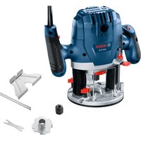
- GMF | GOF | GKF 1600 CE Professional
- Entsorgung
- General Power Tool SafetyWarnings
- WARNING
- Work area safety
- Electrical safety
- Personal safety
- Power tool use and care
- Service
- Safety information for plunge routers and edge routers
- | English
- Products sold in GB only:
- Product Description and Specifications
- Intended use
- Product features
- Technical Data
- Noise/Vibration Information
- Fitting
- Inserting the routing motor into the plunge base/ non-plunge base (see figures A-B)
- Separating the routing motor from the plunge unit/nonplunge base (see figure C)
- | English
- Inserting the router bit (see figure D)
- Dust/Chip Extraction
- Fitting the dust extraction adapter on the plunge base (see figure E)
- Fitting the dust extraction adapter on the non-plunge base (see figure F)
- Connecting the dust extraction system
- Operation
- Starting Operation
- Preselecting the speed
- Switching on/off
- Constant electronic control
- Soft start
- Setting the routing depth
- Setting the routing depth on the plunge base (see figure G)
- 24|English
- Setting the routing depth on the non-plunge base (see figure H)
- Working Advice
- Routing direction and routing process (see figure I)
- Routing with the plunge base
- Routing with the non-plunge base
- Routing with an auxiliary guide (see figure J)
- Routing with a parallel guide (see figure K)
- Routing with a router compass (see figure L)
- Routing with a guide rail (see figure M)
- Routing with the guide bushing (see figures N-Q)
- Routing process
- Centring the base plate (see figure R)
- Working with a router table (see figure S)
- Routing with an extraction hood (see figures T-U)
- Maintenance and Service
- Maintenance and Cleaning
- | Français
- After-Sales Service and Application Service
- Great Britain
- You can find further service addresses at:
- Disposal
- Only for EU countries:
- Français
- Eliminación
- Eliminação
- Smaltimento
- Afvalverwijdering
- Bortskaffelse
- Du hittar fler kontaktuppgifter till service har:
- Avfallshantering
- Stille inn turtallet
- Stille inn freesybde
- Deponering
- Havitys
- UuvapuOaoyon
- Epyaia ie panetippeapiaqatoc (Bene eukova S)
- Anoupon
- Movi yia xwpec tnc EE:
- Tasfiye
- System Constant Electronic
- Utylizacja odpadów
- Likvidace
- Likvidácia
- Eltavolitas
- KpntepnnpdeBbIXcoCTOHH
- Tnn n nepnoohoctb texnueckoro 6cnyxnbann
- | Pycsckn
- XpAHHeHne
- TpaHcnpToPobKa
- Yka3aHnnoTexHnke6e3onacHOCTn
- 06uye yka3aHnno TExnke 6e3onachocTH nIa 3NeKtpoHHCTpyMeHTOB
- NPEyPEXJEHNE
- CoxpaHnIe 3TH HnCTpyKuNN yKa3aHHN dnn 6yduero nCNoB3OBAHHN.
- Be3onacnoctb pa6oery mecta
- 3neKtpo6e30nachocTb
- Be3oNaChocThIIODei
- PpHmHeHHe 3eKtpOnnHcTpymEnHa N o6paIeHne C HMM
- CepBnC
- Yka3aHnno TEOxHnke 6e3oNaCHOCTn dna fpe3epHBIX CTAHKOB NKPOMOHybIX fpe3epOB
- Onncahne npoodykta n ycnyr
- PpHMeHeHne no Ha3HaueHHIO
- H3o6paXeHHbIe COCTaBhIbe qactn
- Texnueckne daHbIe
- YdaneHne nbinn n ctpyKKn
- MOnTaX aAnTePa nbIeYdaneHn Ha nOrpyxKn 6nok (cm.pnc.E)
- MONTAX aanTepa nbineydaeneHn Ha konnpoBbHbI 6nok (cm.pnc.F)
- PtpcoeHHHeHyeCtPoIcTBaBbJeYdaENn
- Pa6ota c HhctpymehTom
- BknloueHne 3nEeKtpOnHcTpymeHa
- HacrpoKa uCnA o6oPoTob
- Yka3aHHIIO IIpHMeHeHHIO
- 162|yKpaHcbKa
- Yttnn3aun
- Tolbko dIa cTpaH-ueNoB EC:
- yKpaIHcbka
- Bka3iBkn 3 texhikn 6e3nekn
- 3araIbHI BkA3IBKN 3TexHIKN 6e3neKn dIeNEKtpoiHCTpyMeHTB
- NONEPE-IXEHHA
- O6pe 36epiraTe Ha MaHyTHe ci nonepeJxHnI Bka3iBKn.
- Be3neka ha po6ooyMo micui
- EneKtpnHa 6e3neka
- Be3neKaIIOeI
- IpaBnIbHe NOBoJxKeHHa Ta KOpNcTyBaHna eNeKtpoHcTpymeHTamH
- Cepbic
- Bka3iBkn 3 texhikn 6e3neKn dIy fpe3epHnx BepCTaTIB i KpOMKOfpe3epHnx BepCTaTIB
- 166|YkpaHcbKa
- MOHTAX
- BctaHOBHeHHaΦpe3epHoroDbHryHa y 3aHypOBaIbHOMy/KoJIIOBaIbHOMy 6nouci (INB.MaI.A-B)
- 3HHTTfpe3epHOro DnHyHa i3aHpyBoanbHorO/ KonioBaHbHorO 6noka (mB.Man.C)
- BiDCMOKryBaHHnHy/TnpCh/ctpyx
- MoTtAK BIDCMOKrYBaIbHoro aadTepeHa 3aHypoBaIbHomy 6Noci (nB.Man.E)
- MOHTAX BIDCMOKTyBaHOro aAnTepa Ha koniOBaHOMy 6noci (nB.Man.F)
- PiD'EDHANH CNCTEM NIOBIDCMOKTyBaHH
- Po6ota
- Noataokpo60tn
- BctahOBnEnHH KInbKocti o6eptIB
- YbIMKHeHHBmKHeHH
- NocTiHa eneKtpoHika
- PnaBnIyck
- HactpoIOBAHHrIIN6HHnΦpe3epyBaHH
- HactpoIOBaanrnn6nHHppe3epyBaHHHa 3aHypoBbHomy 6noi (mB. Man. G)
- 168|yKpaHcbKa
- HaCtpoIOBaanHrIIN6HHnΦpe3epyBaHHHa koniIOBaIbHOMy 6noci (nB.MaN.H)
- Bka3iBKn 0oO p6oTn
- Hanpromok i npoepypa fpe3epybaHHa (nB. man.1)
- Φpe3epyBaHHI 3aHypoBbHM 6nokom
- Φe3epyBaHH i3 KoniIOBaNbHM 6nOKOM
- Φe3epyBaHHH 3doATKOBm ynpom (nB.MaJ.J)
- KpomkoBe a6o npoipinbHe ppe3epybaHHa
- Φe3epyBaHH3 npaIenbHm ynopom (nB.MaI.K)
- P6oTa3Φpe3epHmCTOnOM(nHB.Man.S)
- Φe3epyBaHH3 BNTAXHHKOBnakOM(Hb.Man.T-U)
- Texhiue 06cnyroByaHHi cepbic
- Texhihe 06cnyroByaHH i ouheneHH
- Cepbic i koncynbtaqii 3 nHTaHb 3actocybaHHA
- YkpaHa
- Apecn iHnX cepBicHN zentpib HabeJeHO HNKe:
- Ytunizuaia
- ПишдякраинEC:
- Ka3ak
- Eypa3n8 3KOHOMHKanbIK OdafbiHa (KeDen OdafbHa) Mywe MemNeKeTtep aymafbIHda KOnDaHbInaBl
- Ehimi nai danany Mep3imi
- Ictehyce6entepinHti3iM
- TainanahyubihbMymkH kTeNikTepi
- Uekri kyn genrinepi
- Kb3met Kepcty Typi MeH xiniri
- CaRTay
- Tacbimanay
- Kayinci3ik HycKaynapbI
- 3neKtp KypanapbI ywiH kannbl Kayinci3ik HycKaynapbl
- ECKEPTY
- Ocbl3neKtp KypalbHbHn HHaBnDaBf eceptynepdi,
- 171Kaa3k
- Bonaawk xmbctap yinH kayinci3ik HycKaynbiktapbMeH eceptnenepe caKTan KObHbI3.
- XymbicopHBiHbKayinci3iri
- 3nektp kayinci3iri
- KeKayinci3ik
- 3neKtp KypanapbH naiDanaHy KHe KTy
- Kb13met Kepctety
- Kypandbiy yctiHEn ophanaactbipbin fpe3epnyre XeHe wetiHEn fpe3epnyre aphanfah Kayinc3ik TexHHKaCbHbH HycKaynapbl
- ΘHIM KxHe Kyat CnnaTamaCbl
- TaFaiBihany6oBihwaKoJdany
- BeHHeneHren Kypamdbi 6nweKTeP
- BaTbIPMaBbI 6nOKTaFbI fpe3epney TepeHdirin petrey (G cypTeIH KapaHbI3)
- 178|Ka3aKa
- Kowipy 6norbHaFbI cpeepney tepeHirin peTey (HCypen KapaHb3)
- PaindanaHy 6oBbHua HycKaynap
- Φpe3epney 6aftbMeH Φpe3epney npoueci (I cypetin kapaht)
- BaTbIPMaBbI 6nokneH pfe3epney
- Kowipy 6norbimn dpeepney
- Komekui tipekenen ppeepney (J cypetin kapaib3)
- XnKTepeHemec npoPmbi pfeepney
- Iapannenb tipekneh fpeepney (K cypetin kapaanbi3)
- Φpe3epney uynkynimen Φpe3epney (L cypetin KapaHbI3)
- BaftaybiuHnHaMeHΦpe3epney (M cypetin KapaHb3)
- Kowipy rnnb3acbImeH ppe3epney (N-Q cypertrepin KapaHb13)
- Kowipy runb3acbHbH iwi dHaMeTpHEn KIi60nAtbH ppe3a dHaMeTpH TaHaHbI3.
- Φe3epney npoueci
- Tipek TaKTaCbIH optara kentipy (R cypetih KapaHb3)
- Φpeepney yctenimeh kymbic ictey (Scyperihkapahb3)
- 180|Ka3aK
- Copfbln kantamameh pfeepney (TUCypetTepin KapaHb3)
- TexHnKaIbIK KytIM XHe Kbl3MeT
- KbI3MeT KepeTy KHe Ta3anay
- TytbHybifa KbI3MeT Kepcety XaHnauHa Kyehctepi
- Ka3akCTah
- KbI3Met Kepcety opTaNbIKTapbIHbH 6aca da MeKeHkaJInapbIH MbHa JKepeH KapaHbI3:
- Kedere kapaTy
- Tek kaHa EO enepi yuin:
- Româna
- Instruţiuni de siguranta
- Sistemul electronic constant
- Pornire lenta
- Eliminare
- Yka3aHnHa 3a cnryphnoct
- PPEyPEX- Ppoetete BCnKn PpeynpeXeH Hn, yKa3aHH, 3aNo3HaIte ce c Hpynte nTexHueckTe Xapak
- CbxpnaHbBaIte Te3n yka3aHHa HcHpyHO MxCTO.
- Be30nachOCT Ha pa60THOTMOrTO
- Be3oNaChocT npna pa6oTa c enEeKtpnueckn ToK
- Be3oNaCeH NaHH Ha pa60Ta
- PnKnBO OTOHeHne KbMe nEKeTPOHNCTpyMeHTNE
- Toudbpkahe
- Yka3aHn 3a6e3oNaChocT 3a 06eppe3n KaHTOBn fpe3n
- 192|Бьлгарский
- OnncahneHa npodykTa n deHocTtA
- PpeHa3NaueHne Ha eNeKtpOnHcTpymeHa
- H306pa3eHH enemeHTn
- TexHHueckn daHHN
- Hhopmaa3a n3buaBn ym n Bn6paan
- Pa6oTeTe c wymo3aIyuIHTenI
- Mонтуранe
- IocTabaHHe Ha MToopaHa φpe3ata B Moynla 3a BpA3BaHc/KoNnpaunna Moyn (Bx. cnr. A-B)
- Pa3kaute MoTopa Ha ppe3ata OT Modyna 3a Bp3BaHe/ Konnpaunu Mdyn (Bx. qnr. C)
- IocTabaHe Ha fpe3epa (Bx. hnr. D)
- PnpopbUba ce npn nocTaBHe H cMaHa Ha ppeepn da pa6oHTe C npedna3Hn pbKaBm.
- Cnctema 3a npaxoynaBHe
- Pa6ota c eneKtpoHHcTpymeHTa
- IyckaneBekcnnoataa
- PpeBapntenHo yctahOBBAhe Ha ckopocTtHa BbptHe
- BkJIIOUbaHe Hn3KJIIOUbaHe
- Modyn 3a noctoHHa ckopoCT Ha BbpTeHe
- ПлавноВКПИЧАнe
- HaCtpoKa Ha dbIb6OuHHa HaΦpe3ObaHe
- HacpoKa Ha b6uHaHa Ha ppe3oBaHe Bbpxy Moyna 3a Bpa3BaHe (Bk. fnr. G)
- HaCtpoKa Ha bIb6OuHHa Ha fpe3oBaHe Bbpxy konHpaunMoyn (Bx. qHr. H)
- Yka3aHn 3a pa60Ta
- 198|BbIgapcKn
- Φe3oBaHe c KOnnpaTa Btynka (Bx. fHr. N-Q)
- H36epete ppeep c no-MaIbK dHaMeTbp OT BbTpewHHaDHaMeTbp Ha KOnHpaaata BtynKa.
- PpoecHaΦpe3Obahe
- LcHTpHaHe hA oCHOBnTa nOoua (Bx. fHr.R)
- Pa6ota c Maca 3a ape30BaHe (Bk. mHr. S)
- Φe3oBaHe c npaxoyNoBHTenEn Koxy (Bx. fHr. T-U)
- PoiDlbpxKaHe n cepBn3
- Iopdbpxkane nouHCTBaHe
- KnneTcKa cnx6a H KOHcyntaun OTHoCHOynotpe6ata
- www.bosch-pt.com
- bIra
- DpyrH cepBn3HH apech uie oTKpHeTe Ha:
- Бракуван
- Cama 3a ctpaan oE C:
- MaKeDoHcKn
- Бe36eДнocHH HanomeHH
- OnuTH npdeynpeyBaHa 3a 6e36eHocT 3a eNeKtpuHn anatn
- NPEy- PEPYBAHbE
- 3auybaje rn 6e36eHNOCHNTE npedynpeybaHa ynaTcBA 3a KopHCTebe H 3a BO NdHHa.
- Be36eHocT ha pa6oTHnoT npocToP
- EneKtpnHa 6e36ednoct
- HnHa6e36eHnoCT
- Ynortpe6a nuybahe ha enektpnuHte anatn
- CepBncnpahe
- Be36eHocn HanoMeHH 3a noBpuHHckn aroHn rnoDankn
- Onnc Ha npoN3BODOTn nepΦopMaHcHTe
- YnoTpe6a co cooDbetHa HameHa
- Hnyctpaunja ha KOMnOHeHTN
- | MaKeDoHcKn
- Texnukn noaToun
- HnΦopMaun 3a 6yuaB/BN6paun
- MOHTaxa
- BmTeHyBaBe MoTOp 3a rnoDaBe BO eHNHua 3a Bnna6HyBaBe/eHNHua 3a KonnpaBe (BnDn CnKn A-B)
- Baene ha motopot 3a rnoDahe oednHuaTa 3a Bna6hyBaHe/eHNHuaTa 3a konnpaBe (BnDn CnHa C)
- BmTeHyBaHe Ha rnoJaNkata (BnH cnNka D)
- PnCtBaBeHMeHyBaBeHaTNOdaKata ce npenopayBa Hocbe Ha 3aWTHN paKaBnU.
- Tnoaankte 3a cehe he Ha uBpct Mean (HM) ce
- BumkyBaBe Ha npab/ctpyrotHH
- MoHTnpaBe Ha aanTep 3a BCncyBaHe Ha eHHnUata 3a Bnna6HyBaHe (BmH cnHa E)
- MOnTnpaBe Ha aanTpep 3a BCncyBaBe Ha eHHncaTa 3a konnpaBe (BnDn cnnkaF)
- PpHKnyBaBe Ha BCNCyBaay 3a npab
- Ynortpe6a
- CtabaBeBoynotpe6a
- Bipahe Ha 6pojTo Ha BpTeKx
- BknyBaBe/ncKyBaBe
- KoHCTaTHa eNekTpOHnKa
- ΦHH CTAPT
- IopocyBaHbe Ha dna6oMHnHaTa 3a rnoDahe
- IpoecyBaBe Ha nla6oHnHa Ta gnOdaBe eHHnUaTa 3a Bna6HyBaBe (BnDn cnka G)
- IpoecyBaHe Ha nla6oHnHa Ta HrnoDaBe eHNnCata 3a konnpaBe (BnDn CnKa H)
- Cobetn npa6oTeheTo
- Ppabeu npoec Ha rnoDahe (BnDn cInkaI)
- IIOdaBe co eunnua 3a Bna6HyBaBe
- IIOaBe co eHNHua 3a KOINHpAbe
- TIOdahe co nOmoWeH rpaHnHnK (BnD cHnKa J)
- 06nkyBaIbe HIOdaIbe Ha pa6oBu
- Inoahe co npapanen HpahnHnK (BnncnKa K)
- ItoaBe co wecTap 3a ItoaBe (BnDn CnKa L)
- TnOdahe co wHbAoDnKa (BnH cNkA M)
- Tlodahe co konnpnata yaypa (BnH cnNk N-Q)
- > N36epete noman djuameTap Ha rnoaKaT a O BhatpeHHOT djuameTap Ha KOHNpHaTa Caypa.
- Ppoec Ha rnoDahe
- LcHtpnpahe ha oChOBHaTAnOua (BmCnkaR)
- IOnonHnTeHH aDpeCN Ha cepBnCn MoKe da Hajne Ioo:
- OtctpaHyBaBe
- Cama 3a 3emjnte oEY:
- Srpski
- Uklanjanje dubreta
- Samo za EU-zemlje:
- Slovenscina
- Varnostna opozorila
- Splośna varnostna navodila za elektricka orodja
- OPOZORILO
- Odlaganje
- Zbrinjavanje
- yaaai Jlss
- (Dgjgljbl)jjlaaJc
- (Ljgll jaii jaiil jalp aaiy jiaill
- auij 10
- aJg aJ
- SjSloc
- sjlolj
- aW|g0sJ uS
- Sis gaj) Sos ojjla 1s jjjogai (Jgai
- uugw9 CJ1j0
- juiu L o jglua g lo
- oLwJsAeOJjI
Brand : BOSCH
Model : GMF 1600 CE Professional
Category : Milling machine