GOF 13-25 Professional - Milling machine BOSCH - Free user manual and instructions
Find the device manual for free GOF 13-25 Professional BOSCH in PDF.

| Product Type | Plunge Router (Trim Router) Corded |
| Brand | Bosch |
| Model | GOF 13-25 Professional |
| Rated Power | 1300 W |
| No-load Speed | 11000 – 28000 rpm (electronic adjustment) |
| Maximum Router Bit Diameter | 38.1 mm (1-1/2 in) |
| Collet Size | 6.35 mm (1/4 in) |
| Power Supply | Mains 230 V AC, 50/60 Hz |
| Weight | 4.0 kg (approx.) |
| Plunge Function | Yes, with locking lever and adjustable depth stop |
| Speed Variation | Electronic, 6 positions on dial |
| Guiding System | Edge guide (included), template guide (optional), parallel guide |
| Dust Extraction | Adaptable dust hood (vacuum) |
| Safety Device | Double insulation, spindle lock, lock-on/off button |
| Machinable Materials | Wood, plastics, fibreboards, aluminum up to 15 mm thickness |
| Routine Maintenance | Cleaning ventilation slots with damp cloth or compressed air |
| Available Spare Parts | Collets, router bits, guides, dust hood |
| Warranty | Limited manufacturer's warranty (see Bosch website) |
Frequently Asked Questions - GOF 13-25 Professional BOSCH
User questions about GOF 13-25 Professional BOSCH
0 question about this device. Answer the ones you know or ask your own.
Ask a new question about this device
Download the instructions for your Milling machine in PDF format for free! Find your manual GOF 13-25 Professional - BOSCH and take your electronic device back in hand. On this page are published all the documents necessary for the use of your device. GOF 13-25 Professional by BOSCH.
USER MANUAL GOF 13-25 Professional BOSCH
| Safety SymbolsThe definitions below describe the level of severity for each signal word.Please read the manual and pay attention to these symbols. | |
 | This is the safety alert symbol. It is used to alert you to potential personal injury hazards. Obey all safety messages that follow this symbol to avoid possible injury or death. |
 | DANGER indicates a hazardous situation which, if not avoided, will result in death or serious injury. |
 | WARNING indicates a hazardous situation which, if not avoided, could result in death or serious injury. |
 | CAUTION indicates a hazardous situation which, if not avoided, could result in minor or moderate injury. |
Table of Contents
General Power Tool Safety Warnings ..... 3
Safety Warnings for Routers. 4
Additional Safety Warnings .... 5
Disposal 5
Intended Use .... 5
Symbols....6
Specifications 7
Getting to Know Your GOF13-25 Corded Plunge Router....8
Assembly and Adjustments.....10
Router Bits 10
Replacing the Collet ..... 11
Installing the Dust Extraction Hood ... 12
Installing and Removing the Chip Guard 12
Installing the Template Guide (optional accessory) 12
Edge Guide Assembly 13
Convert Edge Guide into Circle Guide 13
Operation 14
Plunging Action 14
Setting Depth of Cut 14
Operating the Plunge Router.....15
Feeding the Router 16
Rate of Feed 17
Routing Tips 17
Guiding the Router 18
Maintenance 21
General Maintenance ..... 21
Service 21
Cleaning. 21
Storage and Maintenance ..... 21
Accessories 22
Troubleshooting. 22
General Power Tool Safety Warnings
WARNING
Read all safety warnings, instructions, illustrations and specifications provided with this power tool. Failure to follow all instructions listed below may
result in electric shock, fire and/or serious injury.
SAVE ALL WARNINGS AND INSTRUCTIONS FOR FUTURE REFERENCE.
The term "power tool" in the warnings refers to your mains-operated (corded) power tool or battery operated (cordless) power tool.
1. Work area safety
a. Keep work area clean and well lit. Cluttered or dark areas invite accidents.
b. Do not operate power tools in explosive atmospheres, such as in the presence of flammable liquids, gases or dust. Power tools create sparks which may ignite the dust or fumes.
c. Keep children and bystanders away while operating a power tool. Distractions can cause you to lose control.
2. Electrical safety
a. Power tool plugs must match the outlet. Never modify the plug in any way. Do not use any adapter plugs with earthed (grounded) power tools. Unmodified plugs and matching outlets will reduce risk of electric shock.
b. Avoid body contact with earthed or grounded surfaces, such as pipes, radiators, ranges and refrigerators. There is an increased risk of electric shock if your body is earthed or grounded.
c. Do not expose power tools to rain or wet conditions. Water entering a power tool will increase the risk of electric shock.
d. Do not abuse the cord. Never use the cord for carrying, pulling or unplugging the power tool. Keep cord away from heat, oil, sharp edges or moving parts. Damaged or entangled cords increase the risk of electric shock.
e. When operating a power tool outdoors, use an extension cord suitable for outdoor use. Use of a cord suitable for outdoor use reduces the risk of electric shock.
f. If operating a power tool in a damp location is unavoidable, use a Ground Fault Circuit Interrupter (GFCI) protected supply. Use of a GFCI reduces the risk of electric shock.
3. Personal safety
a. Stay alert, watch what you are doing and use common sense when operating a power tool. Do not use a power tool while you are tired or under the influence of drugs, alcohol or medication. A moment of inattention while operating power tools may result in serious personal injury.
b. Use personal protective equipment. Always wear eye protection. Protective equipment such as a dust mask, non-skid safety shoes, hard hat or hearing protection used for appropriate conditions will reduce personal injuries.
c. Prevent unintentional starting. Ensure the switch is in the off-position before connecting to power source and/or battery pack, picking up or carrying the tool. Carrying power tools with your finger on the switch or energizing power tools that have the switch on invites accidents.
d. Remove any adjusting key or wrench before turning the power tool on. A wrench or a key left attached to a rotating part of the power tool may result in personal injury.
e. Do not overreach. Keep proper footing and balance at all times. This enables better control of the power tool in unexpected situations.
f. Dress properly. Do not wear loose clothing or jewelry. Keep your hair and clothing away from moving parts. Loose clothes,
General Power Tool Safety Warnings
jewelry or long hair can be caught in moving parts.
g. If devices are provided for the connection of dust extraction and collection facilities, ensure these are connected and properly used. Use of dust collection can reduce dust-related hazards.
h. Do not let familiarity gained from frequent use of tools allow you to become complacent and ignore tool safety principles. A careless action can cause severe injury within a fraction of a second.
4. Power tool use and care
a. Do not force the power tool. Use the correct power tool for your application.
The correct power tool will do the job better and safer at the rate for which it was designed.
b. Do not use the power tool if the switch does not turn it on and off. Any power tool that cannot be controlled with the switch is dangerous and must be repaired.
c. Disconnect the plug from the power source and/or remove the battery pack, if detachable, from the power tool before making any adjustments, changing accessories, or storing power tools. Such preventive safety measures reduce the risk of starting the power tool accidentally.
d. Store idle power tools out of the reach of children and do not allow persons unfamiliar with the power tool or these instructions to operate the power tool.
Power tools are dangerous in the hands of untrained users.
e. Maintain power tools and accessories. Check for misalignment or binding of moving parts, breakage of parts and any other condition that may affect the power tool's operation. If damaged, have the power tool repaired before use. Many accidents are caused by poorly maintained power tools.
f. Keep cutting tools sharp and clean. Properly maintained cutting tools with sharp cutting edges are less likely to bind and are easier to control.
g. Use the power tool, accessories and tool bits etc. in accordance with these instructions, taking into account the working conditions and the work to be performed. Use of the power tool for operations different from those intended could result in a hazardous situation.
h. Keep handles and grasping surfaces dry, clean and free from oil and grease. Slippery handles and grasping surfaces do not allow for safe handling and control of the tool in unexpected situations.
5. Service
a. Have your power tool serviced by a qualified repair person using only identical replacement parts. This will ensure that the safety of the power tool is maintained.
Safety Warnings for Routers
Hold the power tool by insulated gripping surfaces only, because the cutter may contact its own cord. Cutting a "live" wire may make exposed metal parts of the power tool "live" and could give the operator an electric shock.
Use clamps or another practical way to secure and support the workpiece to a stable platform. Holding the work by your hand or against the body leaves it unstable and may lead to loss of control.
SAVE THESE INSTRUCTIONS
Additional Safety Warnings
To reduce the risk of injury, always wear safety goggles or glasses with side shields. The operator and other people in the work area must wear eye protection in accordance with ANSI Z87.1. Eye protection does not fit all operators in the same way. Make sure the eye protection chosen has side shields or provides protection from flying debris both from the front and sides. The employer is responsible for enforcing the use of eye protection by the operator and other people in the work area. When required, wear head protection in accordance with ANSI Z89.1.
WARNING
Some dust created by power sanding, sawing, grinding, drilling, and other construction activities contains chemicals known to cause cancer, birth defects or other reproductive harm. Some examples of these chemicals are:
- Lead from lead-based paints,
- Crystalline silica from bricks and cement and other masonry products, and
- Arsenic and chromium from chemically-treated lumber.
Your risk from these exposures varies, depending on how often you do this type of work. To reduce your exposure to these chemicals: work in a well ventilated area, and work with approved safety equipment, such as those dust masks that are specially designed to filter out microscopic particles.
Disposal
This section is part of Robert Bosch Tool Corporation's commitment to preserving our environment and conserving our natural resources.
Tool Disposal
Do not dispose of power tools and batteries/rechargeable batteries into household waste!
Intended Use
WARNING
Use this router only as intended. Unintended use may result in personal injury and property damage.
This router is intended for routing grooves, edges, profiles, and elongated holes as well as for template routing in wood, plastic, and light
building materials such as drywall with 1/4" (6.35 mm) shank router bits having a diameter of up to 1-1/2" (38.1 mm). It can also be used for routing of aluminum flat-stock and extrusions, up to 0.59" (15 mm) thick, at low speeds and with compatible router bits. This router is not intended for use in a router table.
SAVE THESE INSTRUCTIONS
Symbols
Important: Some of the following symbols may be used on your tool. Please study them and learn their meaning. Proper interpretation of these symbols will allow you to operate the tool better and safer.
| Symbol Designation/Explanation | |
| V Volts (voltage) | |
| A Amperes (current) | |
| Hz Hertz (frequency) | |
| lb Pounds (weight) | |
| kg Kilograms (weight) | |
| ft Feet (length) | |
| in Inches (length) | |
| m Meter (length) | |
| cm Centimeter (length) | |
| min Minutes (time) | |
| s Seconds (time) | |
| Diameter (size of drill bits, grinding wheels, etc.) | |
| n0 No load speed (rotational speed at no load) | |
| n Rated speed (maximum attainable speed) | |
| .../min | Revolutions or reciprocation per minute (revolutions, strokes, surface speed, orbits etc. per minute) |
| F Fahrenheit (temperature) | |
| C Celsius (temperature) | |
| Arrow (action in the direction of arrow) | |
| Alternating current (type or a characteristic of current) | |
| Class II construction (designates double insulated construction tools) | |
| This symbol designates that this tool is listed by the Canadian Standards Association, to United States and Canadian Standards. | |
| Alerts user to read manual. | |
| Alerts user to wear eye protection. | |
Symbols
Important: Some of the following symbols may be used on your tool. Please study them and learn their meaning. Proper interpretation of these symbols will allow you to operate the tool better and safer.
| Symbol Designation/Explanation | |
 | Alerts user to wear hearing protection. |
 | Alerts user to wear respiratory protection. |
 | Alerts user to use eye, hearing, and respiratory protection. |
Specifications
| Model Number GOF13-25 | |
| Rated power input 1300 W | |
| No load speed 11,000 | -28,000 RPM |
| Max bit size 1-1/2 in | |
| Collet size 1/4 in | |


Getting to Know Your GOF13-25 Corded Plunge Router
Fig. 1
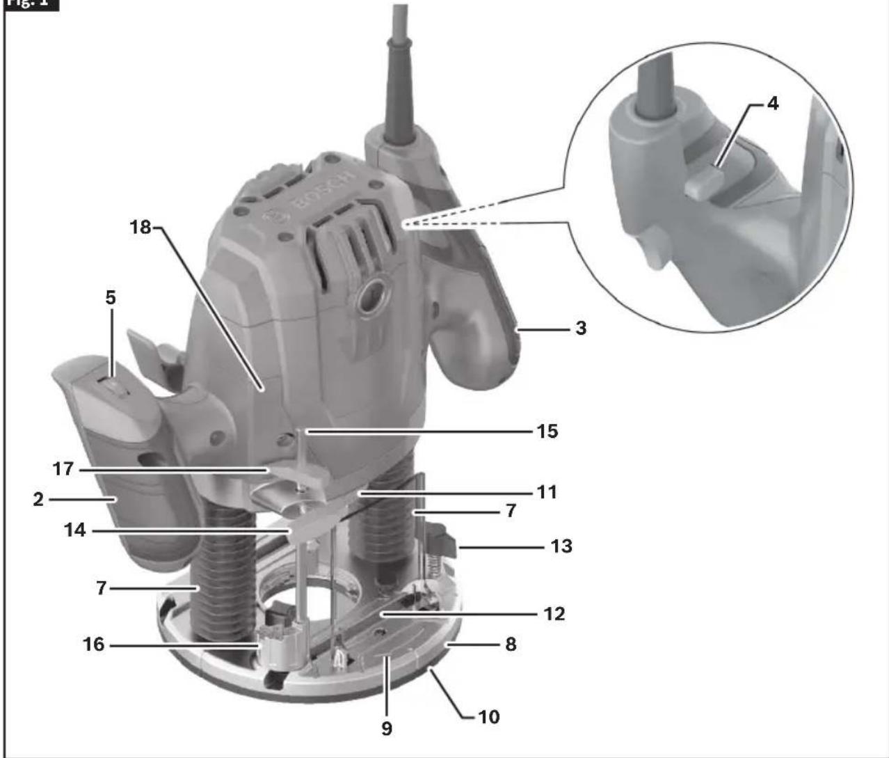
1 Trigger Switch
2 Left Handle (Insulated Gripping Surface)
3 Right Handle (Insulated Gripping Surface)
4 Lock Out/ON Button
5 Variable Speed Dial
6 Plunge Lock Lever
7 Plunge Posts
8 Base
9 Direction of Rotation
10 Subbase
11 Spindle Lock
12 Chip Guard
13 Wing Bolt
14 Thumb Screw
15 Depth Rod
16 Depth Stop Turret
17 Depth Indicator
18 Depth Scale
19 Template Guide Release Lever
20 Edge Guide
21 Edge Guide Rod
Getting to Know Your GOF13-25 Corded Plunge Router
Fig. 2
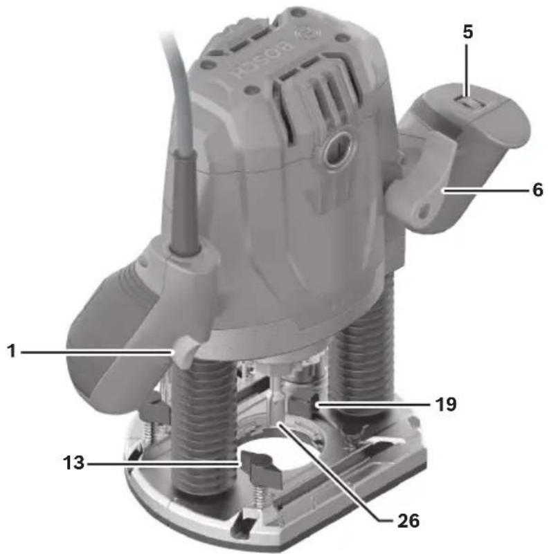
Fig. 3
22 Wrench
23 Dust Extraction Hood
24 Wing Nut for the Centering Pin
25 Centering Pin
26 Router Bit*
* Accessories shown or described are not included with the product as standard.
Assembly and Adjustments
WARNING
Disconnect the plug from the power source before making any adjustments, changing accessories, or storing power tools. Such preventive safety mea-
sures reduce the risk of starting the power tool accidentally.
Router Bits
WARNING
Use only router bits that have shank diameters that
match the installed collet. Using a router bit that has a smaller shank could cause the bit to come loose during operation and become a projectile.
WARNING
Never operate router bits at speeds that are higher
than their maximum rated speed. Router bits running faster than their rated speed can break and fly apart.
Selecting Router Bits
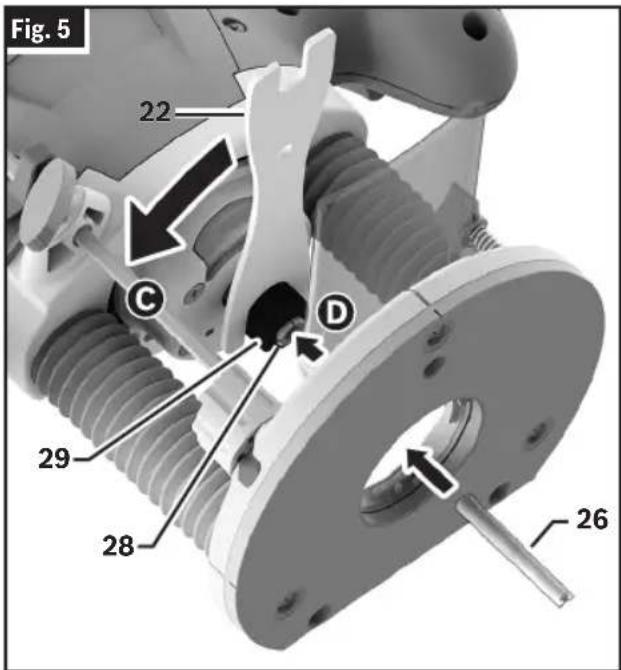
(Fig. 5)
This tool is designed for a wide variety of routing applications that use 1/4" shank bits. These include woodworking applications such as edge forming, grooving, and sign making. This router is also ideal for trimming laminates, phenolics, and other materials that have been bonded to a substrate typically with an overhang of the substrate by about 1/8" (3 mm). A wide assortment of Router Bits 26 with different profiles are available as accessories. Only use good quality bits.
Installing/Removing a Router Bit
(Fig. 4, Fig. 5, Fig. 6)
WARNING
Do not use Cutter diameter larger than 1-1/2". Us-
ing cutter larger than 1-1/2" may damage the router and result in personal injury.
WARNING
Do not tighten Collet without a bit. Tightening Collet
without a bit inserted may cause damage to the tool.
Before attaching the selected Router Bit 26, ensure that the Spindle 27, Collet 28, Collet Nut 29, and Router Bit 26 shank are clean. The Router Bit 26 shank must be straight, undamaged, and an appropriate size in relation to the Collet 28.
-
Pull the Chip Guard 12 downward
-
Place the router upside down or lay it on its side with the flat side of the Base 8 resting on the bench.
-
Press and hold the Spindle Lock 11B to prevent rotation of the Collet Nut 29.
Note: It may be necessary to rotate the Collet Nut 29 to engage the Spindle Lock 11.
-
Use the Wrench 22 to loosen the Collet Nut 29 ©
-
If necessary, remove the installed Router Bit 26.
-
Insert the shank of the Router Bit 26 into the Collet 28 D as far as it will go, then back the shank out until the cutters are approximately 1/8" to 1/4" away from the Collet Nut 29 face.
-
With the Router Bit 26 inserted and the Spindle Lock 11 engaged, use the Wrench 22 to firmly tighten the Collet Nut 29
-
Release the Spindle Lock 11 so it is in the unlocked position.
-
Pull the Chip Guard 12 upwards.
Note: To ensure proper gripping of the Router Bit 26 and minimize run-out, the shank of the Router Bit 26 must be inserted at least 5/8".
Assembly and Adjustments
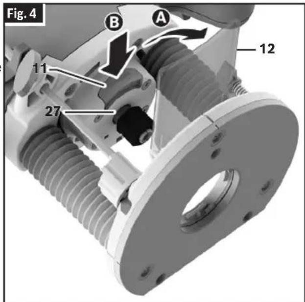
- Lay the router on its side with the flat side of the Base 8 resting on the bench.
- Press and hold the Spindle Lock 11B to prevent rotation of the Collet Nut 29.
Note: It may be necessary to rotate the Collet Nut 29 to engage the Spindle Lock 11.
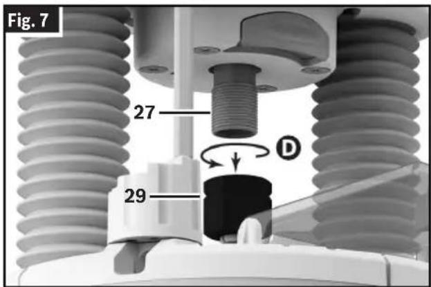
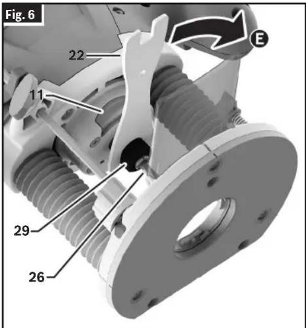
- Use the Wrench 22 to loosen the Collet Nut 29 in a counter-clockwise direction (viewed from the bottom of the router).
- Unscrew and remove the Collet Nut 29 assembly D
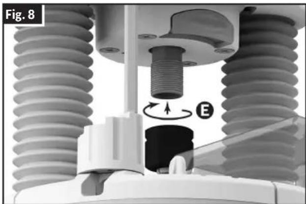
- Ensure that the Spindle 27 threads are clean and the Collet 28 is properly fitted in the Collet Nut 29.
- By hand, screw the new Collet Nut 29 assembly onto the Spindle 27
natural_image
Mechanical assembly diagram showing a threaded component inserted into a housing, with no visible text or symbols.Replacing the Collet
(Fig. 4, Fig. 5, Fig. 7, Fig. 8)
This tool includes a pre-installed 1/4" Collet 28, within the Collet Nut 29, that must be used with a 1/4" diameter accessory shank.
To replace the Collet Nut 29 assembly:
- Pull the Chip Guard 12 downward A
Assembly and Adjustments
Installing the Dust Extraction Hood
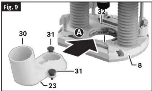
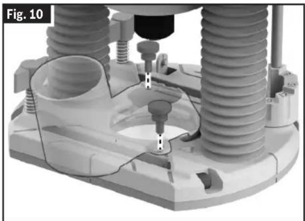
(Fig. 9, Fig. 10)
The Dust Extraction Hood 23 can be installed with the Hose Connection 30 at the front or rear of the Base 8.
-
If you are installing the Dust Extraction Hood 23 with the Hose Connection 30 at the front, then remove the Chip Guard 12 as described in "Installing and Removing the Chip Guard" on page 12
-
Remove the Thumb Screws 31 from the Dust Extraction Hood 23.
-
Insert the Dust Extraction Hood 23 into the opening of the Base 8A
-
Align the holes in the Dust Extraction Hood 23 to the matching Holes 32 in the Base 8 and secure the Dust Extraction Hood 23 in place with the Thumb Screws 31 B
-
Connect the Dust Extraction Hood 23 to a vacuum using a friction fit nozzle.
natural_image
3D mechanical assembly diagram showing threaded components and a central fastener (no text or symbols)Installing and Removing the Chip Guard
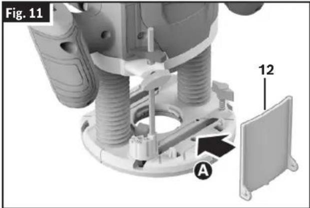
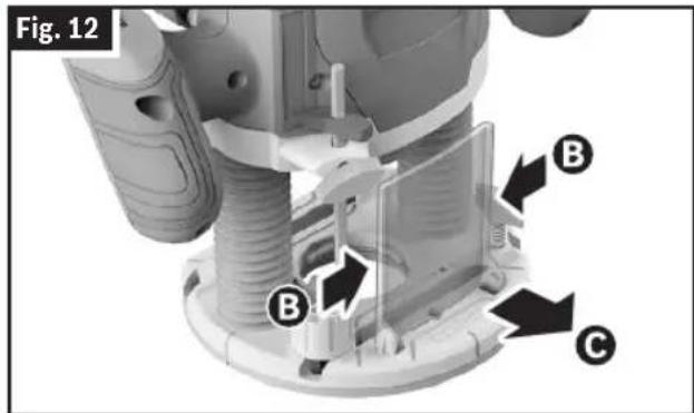
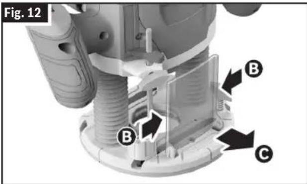
(Fig. 11, Fig. 12)
To install the Chip Guard 12, push it into the guide from the front so that it clicks into place A.
To remove the Chip Guard 12, hold the sides of the Chip Guard 12 and pull the Chip Guard 12 forwards C
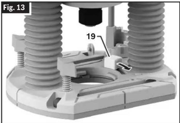
Installing the Template Guide (optional accessory)
(Fig. 13, Fig. 14)
- Pull back and hold the Template Guide Release Lever 19.
- Align the slot configuration and insert the Template Guide 33 into the Template Guide Adapter 34 from below. The coding cams must audibly click into the recesses of the Template Guide 33.
- Release the Template Guide Release Lever 19.
Assembly and Adjustments
- Make sure that the Template Guide 33 is properly secured inside the Template Guide Adapter 34.
natural_image
Mechanical assembly diagram showing two springs mounted on a base with a labeled component (19), no readable text or symbols present.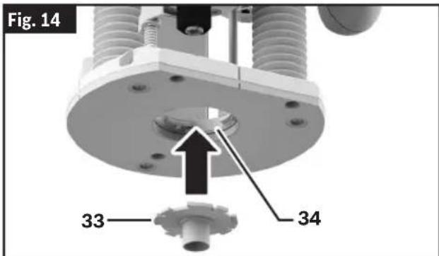
Edge Guide Assembly
(Fig. 15)
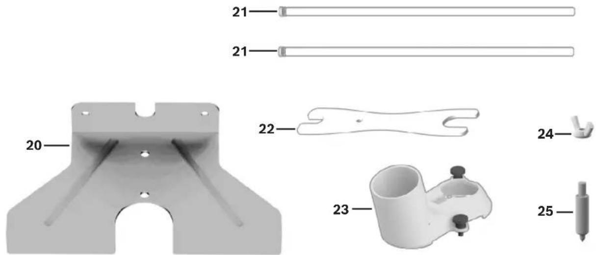
The Edge Guide 20 requires assembly before use as the Edge Guide 20 and Edge Guide Rods 21 are shipped as separate pieces.
- Unscrew the Screw and Washers 35 from one Edge Guide Rod 21, leaving the washers on the screw.
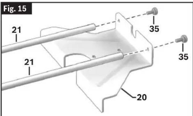
- With the washers in place, insert the Screw 35 into the Edge Guide 20 from the outside of the narrow end.
- Place the Edge Guide Rod 21 on the inside of the narrow end of the Edge Guide 20 and onto the Screw 35.
- Tighten the Screw 35 to secure the Edge Guide Rod 21 to the Edge Guide 20.
- Repeat steps 1 - 4 with the other Edge Guide Rod 21.
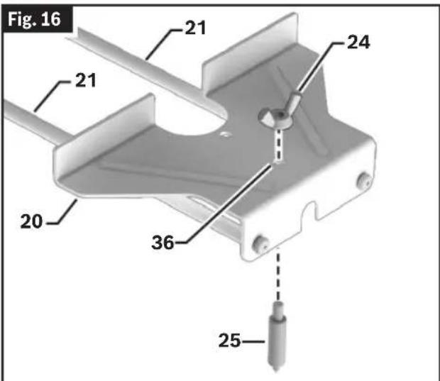
Convert Edge Guide into Circle Guide
(Fig. 1, Fig. 16)
The Edge Guide 20 can be converted into a circle guide by mounting a Centering Pin 25.
- Flip the Edge Guide 20 so that the Edge Guide Rods 21 are underneath it.
- Fit the Centering Pin 25 through the Hole 36 on the Edge Guide 20 from the bottom. Place and tighten the Wing Nut for the Centering Pin 24 from the top of the Edge Guide 20 to secure it in place.
Before using the Edge Guide 20 as a circle guide, always ensure the conical tip of the Centering Pin 25 is fully in the workpiece and securely anchors the Centering Pin 25 on the work surface. Confirm the Base 8 of the router is resting fully on the work surface before beginning routing operations.
Operation
WARNING
Disconnect the plug from the power source before making any adjustments, changing accessories, or storing power tools. Such preventive safety mea-
sures reduce the risk of starting the power tool accidentally.
WARNING
Use personal protective equipment. Always wear eye protection. Protective equipment such as a dust mask, non-skid safety shoes, hard hat, or hearing appropriate conditions will reduce personal injuries.
Bosch plunge routers are designed for speed, accuracy, and convenience in performing cabinet work, routing, fluting, beading, cove cutting, dovetails, etc. This will enable you to accomplish inlay work, decorative edges, and many types of special carving.
Plunging Action
The plunge feature simplifies depth adjustments and will allow the cutting bit to easily and accurately enter the workpiece.
Setting Depth of Cut
To Lower the Router
(Fig. 17)
To lower the router:
- Push the Plunge Lock Lever 6 to the left A.
- Apply downward pressure using the Left and Right Handles 2, 3 until you reach the desired depth B
- Release the Plunge Lock Lever 6C. If necessary, push the Plunge Lock Lever 6C to fully lock it.
The Plunge Lock Lever 6 is spring loaded and returns automatically to the locked position.
To Raise the Router
(Fig. 17)
To raise the router:
- Push the Plunge Lock Lever 6 to the left A.
- Release pressure on the Handles 2, 3D, and the plunge router will automatically retract the Router Bit 26 from the workpiece.
- Release the Plunge Lock Lever 6C. If necessary, push the Plunge Lock Lever 6C to fully lock it.
The Plunge Lock Lever 6 is spring loaded and returns automatically to the locked position.
It is advisable to retract the Router Bit 26 whenever it is not engaged in the workpiece.
Using the Rod and Turret
(Fig. 17)
The Depth Rod 15 and the Depth Stop Turret 16 are used to control cutting depth as follows:
- Set the Depth Stop Turret 16 to the lowest step. The Depth Stop Turret 16 audibly clicks into place.
- With the bit installed, push down the Plunge Lock Lever 6A and apply downward pressure using the Handles 2, 3 B until the tip of the Router Bit 26 just contacts the level surface the router is sitting on. Then release the Plunge Lock Lever 6C. If necessary, push the Plunge Lock Lever 6 C to fully lock it. This is the "zero" position, from which further depth adjustments can be accurately made.
- Rotate the Depth Stop Turret 16 until the desired step is aligned with the Depth Rod 15. Use taller steps for more shallow plunge depths or the first pass for deeper cuts.
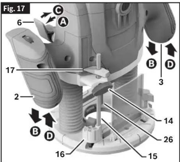
Operation
- Loosen the Thumb Screw 14 and lower the Depth Rod 15 until it contacts the step of the Depth Stop Turret 16.
- Slide the Depth Indicator 17 until it indicates zero on the Depth Scale 18, indicating the point at which the bit just contacts the workpiece.
- Slide the Depth Rod 15 up until the Depth Indicator 17 reaches the desired cutting depth and secure the Depth Rod 15 in position by firmly tightening the Thumb Screw 14. Take care not to accidentally move the Depth Indicator 17.
- The desired depth of cut may now be achieved by plunging the router until the Depth Rod 15 contacts the Depth Stop Turret 16.
Alternate Set-Up for Depth of the Rod and Turret
(Fig. 17)
- Place a jig at the desired routing depth (such as a hinge which needs to be mortised) on the bottom step of the Depth Stop Turret 16.
- Loosen the Thumb Screw 14 then lower the Depth Rod 15 until it contacts the jig.
- Secure the rod in position by firmly tightening the Thumb Screw 14.
- Remove the jig.
Deep Cuts
For deep cuts, make several progressively deeper cuts by starting at one depth and then make several subsequent passes, increasing the cutting depth with each pass. To be certain that your depth settings are as desired, you may want to make test cuts in scrap material before beginning work.
Operating the Plunge Router
Trigger Switch
(Fig. 18)
To turn the tool ON, first press the Lock Out/ON Button 4, then press and hold the Trigger Switch 1, and release the Lock Out/ON Button 4.
To turn the tool OFF, release the Trigger Switch 1.
natural_image
3D model of a robotic device with labeled parts, shown from two views: one showing internal components and the other with a handheld device (no text or symbols present)Lock Out/ON Button
(Fig. 1)
WARNING
DO NOT maintain pressure on the Lock Out/On But-
ton after after pressing the Trigger Switch. When the Lock Out/ON Button is pressed continually the Trigger Switch cannot be released and the router cannot be turned OFF.
Your router is also equipped with a Lock Out/ON Button 4 located just above the trigger that allows continuous operation without holding the Trigger Switch 1.
To lock the Trigger Switch 1, press the Lock Out/ON Button 4 while holding the Trigger Switch 1.
To unlock the switch, squeeze and release the Trigger Switch 1. Do not depress the Lock Out/ON Button 4.
Constant Response Control
The Constant Response Control helps maintain the router spindle speed under load.
Variable Speed Dial
WARNING
Never operate router bits at speeds that are higher
than their maximum rated speed. Router bits running faster than their rated speed can break and fly apart.
Operation
The electronic speed control feature allows motor speed to be matched to cutter size and material hardness for improved finish, extended bit life, and higher performance. Speed can be changed while the router is turned on. Adjust the speed only when the bit is not in contact with the cutting surface.
- To increase the speed, rotate the Variable Speed Dial 5 down; the numbers on the dial will increase.
- To decrease the speed, rotate the Variable Speed Dial 5 up; the numbers on the dial will decrease.
The chart below indicates the speed of the setting number on the Variable Speed Dial 5.
| Dial Position Speed | |
| 1-2 Low speed | |
| 3-4 Medium speed | |
| 5-6 High speed |
The following speed chart indicates the recommended Variable Speed Dial 5 position for the given router bit diameter and material. Always refer to the router bit manufacturer for speed and material recommendations.
| Material Router Bit Diameter | Variable Speed Dial Position | |
| Hardwood (Beech) | 0.16"-0.39" (4-10 mm) 5-6 | |
| 0.47"-0.78" (12-20 mm) 3-4 | ||
| >0.87" (22 mm) 1-2 | ||
| Softwood (Pine) | 0.16"-0.39" (4-10 mm) 5-6 | |
| 0.47"-0.78" (12-20 mm) 3-6 | ||
| >0.87" (22mm) 1-3 | ||
| Chipboard | 0.16"-0.39" (4-10 mm) 3-6 | |
| 0.47"-0.78" (12-20 mm) 2-4 | ||
| >0.87" (22 mm) | 1-3 | |
| Plastics | 0.16"-0.59" (4-15 mm) 2-3 | |
| >0.63" (16 mm) | 1-2 | |
| Aluminum | 0.16"-0.59" (4-15 mm) | 1 |
Entering the Workpiece
Always allow the router to reach the set speed before bringing the Router Bit 26 in contact with the Workpiece 38.
Feeding the Router
(Fig. 2, Fig. 19)
This section explains concepts of how to properly feed the plunge router while in operation.
As seen from the top of the plunge router, the Router Bit 26 turns clockwise and the cutting
edges of the Router Bit 26 are positioned to best cut into the Workpiece 38. Therefore, the most efficient cut is made by feeding the plunge router so that the Router Bit 26 turns into the Workpiece 38, not away. The following figure shows proper feed for various cuts. How fast you feed depends on the hardness of the material and the size of the cut. For some materials, it is best to make several cuts of increasing depth.
If the plunge router is hard to control, heats up, runs very slowly, or leaves an imperfect cut, consider these causes:
Operation
- Wrong direction of feed – hard to control.
- Feeding too fast – overloads motor.
- Dull bit – overloads motor.
- Cut is too large for one pass — overloads motor.
- Feeding too slow — leaves friction burns on workpiece.
Feed smoothly and steadily (do not force).
Practice and experience will help with familiarizing how the plunge router sounds and feels when it is working best.
Always hold the plunge router off the workpiece when turning the Trigger Switch 1 ON or OFF.
Contact the Workpiece 38 with the router after the plunge router has reached full speed, and remove it from the Workpiece 38 before turning the Trigger Switch 1 off. Operating in this manner will prolong switch and motor life and will greatly increase the quality of your work.
Rate of Feed
(Fig. 19)
When routing or doing related work in wood and plastics, the best finishes will result if the depth of cut and feed rate are regulated to keep the motor operating at high speed. Feed the plunge router at a moderate rate. Soft materials require a faster feed rate than hard materials. The router may stall if improperly used or overloaded. Reduce the feed rate to prevent possible damage to the tool. Always be sure the Collet Nut 29 is tightened securely before use. Always use Router Bits 26 with the shortest cutting length necessary to produce the desired
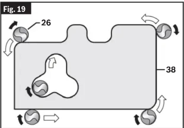
cut. This will minimize Router Bit 26 run-out and chatter. It may be necessary to make the cut in more than one pass with progressively deeper settings to avoid overloading the motor. If the Router Bit 26 cuts freely and the motor does not slow down, the cutting depth is generally correct.
Routing Tips
Always use Router Bits 26 with the shortest cutting length necessary to produce the desired cut. This will minimize Router Bit 26 chatter.
Always be sure the Collet Nut 29 is tightened securely before use.
Soft materials require a faster feed rate than hard materials.
The router may stall if improperly used or overloaded.
Reduce the feed rate to prevent possible damage to the tool.
To be certain that your depth and speed settings provide the desired results, test the settings by routing some scrap material before routing the actual workpiece.
If the router is hard to control, heats up, runs very slowly, or leaves an imperfect cut, consider these causes:
- Wrong direction of feed – hard to control.
- Feeding too fast – overloads motor.
- Dull bit – overloads motor.
- Cut is too large for one pass – overloads motor.
- Feeding too slow – leaves friction burns on work.
When routing deep cuts, it is best to make multiple progressively deeper cuts rather than trying to rout the full depth in one pass. The appropriate depth of cut will depend on the type of material and the type of cutter being used. The GOF13-25 and its multiple-step Depth Stop Turret 16 are ideally suited for multiple pass routing situations. (See “Setting Depth of Cut” on page 14.)
Operation
Exiting the Workpiece
For best control and results, always move the router so that the Router Bit 26 cutter exits from the workpiece before switching off the router.
Operating in this manner will prolong switch and motor life and will greatly increase the quality of your work.
Guiding the Router
(Fig. 1)
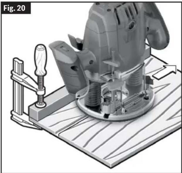
The router can be guided through the workpiece in any of several ways. The method you use depends, of course, on the demands of the particular job and on convenience. For routing operations such as grooving or dadoing, it is often necessary to guide the tool in a line parallel to a straight edge. One method of obtaining a straight cut is to securely clamp a board or other straightedge to the work surface and guide the edge of the router Subbase 10 along this path.
For edge and profile routing without a parallel guide, the Router Bit 26 must be fitted with a pilot pin or a ball bearing. The lower portion of a pilot-tipped Router Bit 26 is a shaft with no cutting edges. Bearing guide Router Bits 26 have a ball bearing to pilot the Router Bit 26.
This pilot slides along the edge of the work as the rotating blades make the cut, forming molding or decorative edges. The edge on which the pilot slides should be perfectly smooth since any irregularities are transferred to the shaped surface. When routing a workpiece that requires edge forming on the endgrain, always rout the endgrain edge before routing the edges that follow the grain. This minimizes the possibility of damage from any blowout at the end of endgrain.
While it is switched ON, guide the router towards the workpiece from the side until the pilot pin or the ball bearing of the Router Bit 26 is touching the side of the workpiece edge that you want to machine.
Guide the router along the workpiece edge. Make sure that the router Base 8 is fully in contact with the workpiece surface, and the Router Bit 26 is perpendicular to the workpiece surface. Excess pressure can damage the edge of the workpiece.
natural_image
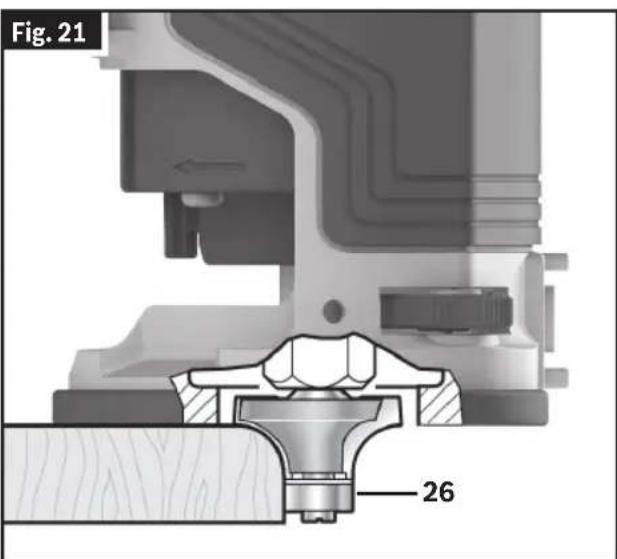
Mechanical assembly diagram showing a drill bit pressing into a workpiece on a wooden base, with no visible text or symbols.Self-Piloted Bits
(Fig. 21)
Self-piloted Router Bits 26 have an integral round tip or ball bearing which rides against the work surface above or below the cutter to control horizontal cutting depth. When using these Router Bits 26, neither the roller guide nor the straight edge guide is required. When guiding against a laminated surface, use wax or other lubricant, and do not apply excess pressure or the piloted end may mar the work. Bearing pilots must be kept clean and free of
Operation
adhesive or other residue. Router Bits 26 bearings are sealed and permanently lubricated, and should be replaced when they no longer turn freely to avoid damaging the work surface.
Routing with the Edge Guide
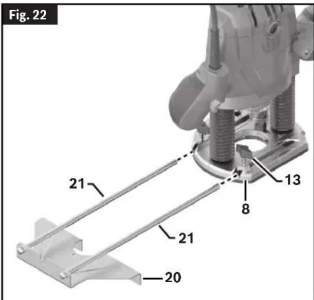
(Fig. 22, Fig. 23)
To attach the Edge Guide 20 to the router Base 8:
- Assemble the Edge Guide 20 according to the instructions in "Edge Guide Assembly" on page 13.

natural_image
Mechanical assembly diagram showing a motor mounted on a metal bracket with a downward arrow indicating motion (no text or symbols)-
Slide the Edge Guide Rods 21 into the router Base 8. For maximum stability, make sure each Edge Guide Rod 21 goes through both holes and protrudes out the other side of the Base 8. (At a minimum, the Edge Guide Rods 21 must be inserted far enough into the router Base 8 that they are both supported from below at a point beyond the fastener on the router.)
-
Securely fasten the router Base 8 to the Edge Guide Rods 21 by tightening the Wing Bolt 13.
With the Edge Guide 20 installed and adjusted, the router should be fed normally, keeping the Edge Guide 20 in contact with the edge of the workpiece at all times.
Routing Curves
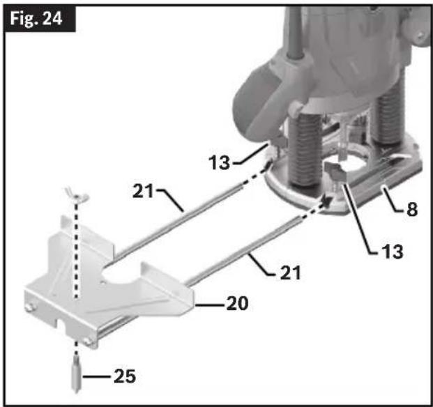
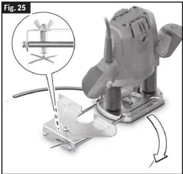
(Fig. 24, Fig. 25, Fig. 26)
-
Assemble the Centering Pin 25 onto the Edge Guide 20 according to the instructions in "Convert Edge Guide into Circle Guide" on page13.
-
Slide the Edge Guide Rods 21 into the Base 8. For maximum stability, make sure each rod goes through both holes and protrudes out the other side of the router base. (At a minimum, the rods must be inserted far enough into the router base that they are both supported from below at a point beyond the fastener on the router.)
-
Securely fasten the router Base 8 to the Edge Guide Rods 20 by tightening the Wing Bolts 13.
-
Push the Centering Pin 25 into the marked center point of the curve and carry out the routing process with a uniform feed.
Before using the Edge Guide 20 as a circle guide, always ensure the conical tip of the Centering Pin 25 is fully in the workpiece and securely anchors the Centering Pin 25 on the work surface. Confirm the Base 8 of the router is resting fully on the work surface before beginning routing operations.
Operation
natural_image
Mechanical assembly diagram showing a motor with a tool inserted, no visible text or symbols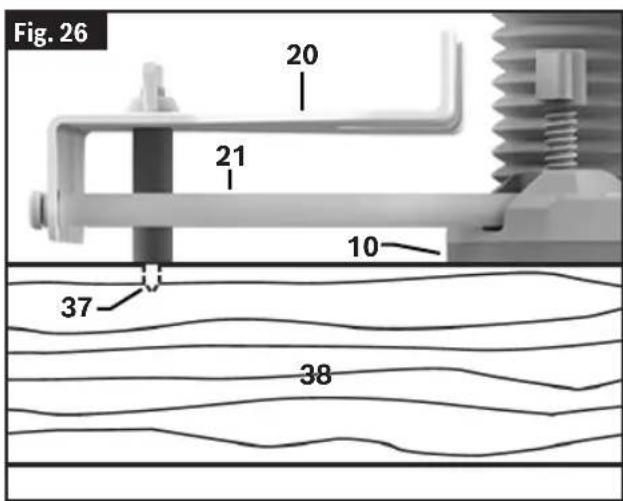
Using Template Guides (optional accessory)
Follow the normal procedure for using the router.
- When a clean round opening in the workpiece is desired, the smoothest surface for the opening will be achieved by moving the router in a clockwise direction.
- When making a round workpiece such as a small tabletop, the smoothest surface for the round workpiece will be achieved by moving the router in a counter-clockwise direction.
Routing with a Template Guide
(Fig. 27)
Using the Template Guide 33, you can transfer contours from templates or patterns to the workpiece.
Select the Template Guide 33 that is suitable for the thickness of the template or pattern. Due to the protruding height of the Template Guide 33, the template must have a minimum thickness of 0.315" (8 mm).
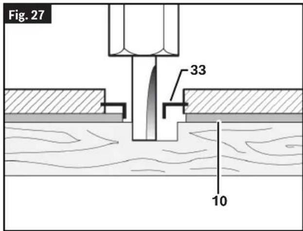
Maximum Bit/Cutter Size for Template Guides
When using a Template Guide 33, use only Router Bit 26 with cutters that are 1/16" less than the internal diameter of the template guide.
To rout with the Template Guide 33, proceed as follows:
Operation
- Insert the Template Guide 33 according to the instructions in "Installing the Template Guide (optional accessory)" on page 12.
- Switch the power tool on and move it with the Template Guide 33 towards the template.
- Push the Plunge Lock Lever 6 down and slowly move the router down until it reaches the set routing depth. Release
the Plunge Lock Lever 6 again to lock this depth. If necessary, push the Plunge Lock Lever 6 up to fully lock it.
- Move the power tool with the protruding Template Guide 33 along the template, applying pressure to the sides.
Maintenance
WARNING
To avoid accidents, always disconnect the tool and/or charger from the power supply before servicing or cleaning.
General Maintenance
Keep your plunge router, and accessories in good working order by adopting a regular maintenance program. Inspect your plunge router for issues such as undue noise, binding of moving parts, breakage of parts, or any other condition that may affect plunge router operation.
Service
WARNING
Have your power tool serviced by a qualified repair
person using only identical replacement parts. This will ensure that the safety of the power tool is maintained.
Cleaning
Certain cleaning agents and solvents damage plastic parts. Some of these are: gasoline, carbon tetrachloride, chlorinated cleaning solvents, ammonia, and household detergents that contain ammonia.
Periodically remove dust from the tool by wiping with a clean rag or using compressed air on the inside of the base and motor unit.
Remove dust and debris from all vents. Keep the plunge router clean, dry, and free of oil or grease. Use only mild soap and a damp cloth to clean the plunge router, since certain cleaning agents and solvents are harmful to plastics and other insulated parts. Some of these include gasoline, turpentine, lacquer thinner, paint thinner, chlorinated cleaning solvents, ammonia, and household detergents containing ammonia. Never use flammable or combustible solvents around tools.
Storage and Maintenance
(Fig. 2)
Store the plunge router and accessories in a cool dry place and avoid freezing. Before use, check Router Bits 26 for cracks and fractures, do not use if damage is suspected.
Accessories
WARNING
Do not use attachments/accessories other than those specified by Bosch.
WARNING Use of attachments/accessories not specified for use with the tool described in this manual may result in damage to tool, property damage, and/or personal injury.
| Accessory Included | Sold Separately | |
| Wrench yes no | ||
| Chip Guard yes no | ||
| Edge Guide yes no | ||
| Template Guide no yes | ||
| Centering Pin yes no | ||
| Dust Extraction Hood yes no | ||
| Extraction Hose no yes |
Troubleshooting
| Trouble Cause Corrective Action | ||
| Router does not operate. Tool temperature too high/low. | Allow plunge router to reach permitted operating temperature. | |
| Plunge router is hard to control. | Incorrect direction of feed. | Reverse the direction of feed.See “Feeding the Router” on page 16. |
| Router runs slow; rough cuts, poor cutting performance. | Dull or damaged Router Bit 26. | Replace Router Bit 26.(See "Installing/Removing a Router Bit" on page 10. |
| Router is overloaded. | Back off the workpiece to reduce the load. | |
| Feeding too fast. Adjust the speed of feed or the router's speed setting. | ||
| Cut is too large for one pass.Make multiple progressively deeper cuts. | ||
| Friction burns on the workpiece. | Feeding too slow. | Adjust the speed of feed or the router's speed setting. |
natural_image
Mechanical assembly diagram showing threaded components and a rotating coil (no text or symbols)natural_image
3D mechanical assembly diagram showing threaded components and a central fastener (no text or symbols)natural_image
Mechanical assembly diagram showing two springs and a central component labeled '19', with no readable text or symbols beyond the label.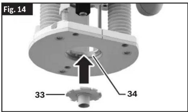
natural_image
3D model of a robotic device with labeled parts, showing internal components and a close-up view (no text or symbols present)Commande Constant Response
natural_image
3D illustration of a sewing machine on a wooden base, showing mechanical components and a clamp (no text or symbols)natural_image
Mechanical assembly diagram showing a motor mounted on a metal frame with a downward arrow indicating motion (no text or symbols)natural_image
Mechanical assembly diagram showing a drill bit being inserted into a workpiece, with no visible text or symbols.
natural_image
Mechanical assembly diagram showing a threaded component and rotating coil (no text or symbols)natural_image
3D mechanical assembly diagram showing threaded components and a central fastener (no text or symbols)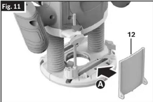
natural_image
Mechanical assembly diagram showing a clamping device with threaded components and a labeled part (19), no readable text or symbols present.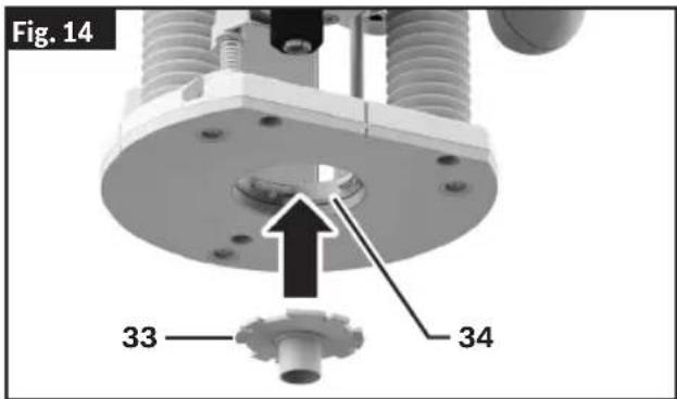
natural_image
3D model of a mechanical device with labeled parts (1, 4), no visible text or symbols beyond labelsnatural_image
Mechanical assembly diagram showing a drill bit pressing into a workpiece on a wooden base, with no visible text or symbols.(Fig. 21)
natural_image
Mechanical assembly diagram showing a motor mounted on a metal bracket with a downward arrow indicating motion (no text or symbols)Fresado de curvas
(Fig. 24, Fig. 25, Fig. 26)
natural_image
Mechanical assembly diagram showing a drill bit with tool path and magnified detail (no text or symbols)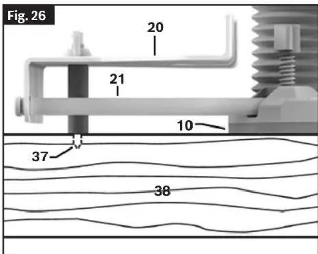
This page was intentionally left blank
This page was intentionally left blank
This page was intentionally left blank
For details on the terms of the limited warranty for this product, go to https://rb-pt.io/PowerToolWarranty or call 1-877-BOSCH99.
GARANTIE LIMITÉE
© Robert Bosch Tool Corporation
1800 W. Central Road
Mt. Prospect, IL 60056-2230
1600A036PC 02/2025