RA1171 Professional - Milling machine BOSCH - Free user manual and instructions
Find the device manual for free RA1171 Professional BOSCH in PDF.

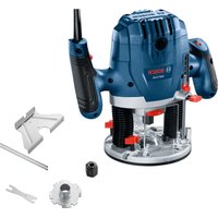
| Product Type | Router Table |
| Brand | Bosch |
| Model | RA1171 Professional |
| Table Dimensions | Approximately 60 x 40 cm |
| Total Weight | Approximately 25 kg |
| Power Supply | 120 V, 15 A max (via integrated switch) |
| Switch Capacity | 15 A, with resetable circuit breaker and key lock |
| Table Top Material | Cast aluminum with T-slots |
| Removable rings included | 3 rings: 1 in, 2 in, 3 in inner diameter |
| Guide | Aluminum guide with adjustable fences (left/right) |
| Bevel guides | 2 bevel guides included (table and guide) |
| Starting pin | Included with guard, for curved machining |
| Miter gauge slot | Yes (45 x 9.5 mm) |
| Dust extraction connection | 2 ports (1/2 in diameter): on the guide and at the back of the stand |
| Main functions | Grooving, edge trimming (with or without pilot bit), joinery, curved pattern work |
| Maintenance and cleaning | Regularly remove dust, check tightness of fasteners, use a vacuum |
| Safety | Lockable switch, overhead guard, bevel guides, push sticks recommended, circuit breaker |
| Available spare parts | Mounting plate, removable rings, bevel guides, switch, locking key |
| Router compatibility | Bosch series 1613, 1617, MR; Craftsman; DeWalt DW616/618; Hitachi M12VC; Makita RF1100/1101; Milwaukee 5615/5616; Porter-Cable 690, 7529, 892-895; Ryobi; Skil 1810-1825 |
Frequently Asked Questions - RA1171 Professional BOSCH
User questions about RA1171 Professional BOSCH
0 question about this device. Answer the ones you know or ask your own.
Ask a new question about this device
Download the instructions for your Milling machine in PDF format for free! Find your manual RA1171 Professional - BOSCH and take your electronic device back in hand. On this page are published all the documents necessary for the use of your device. RA1171 Professional by BOSCH.
USER MANUAL RA1171 Professional BOSCH
IMPORTANT: Read Before Using
natural_image
Silhouette of a person reading a book inside a circle (no text or symbols)Operating/Safety Instructions Consignes de fonctionnement/sécurité Instrucciones de funcionamiento y seguridad
RA1171
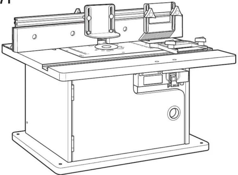
natural_image
Technical line drawing of a mechanical machine with mounting base and workpiece (no text or symbols)BOSCH
Consumer Information Renseignement des consommateurs Información para el consumidor
Toll Free Number: Appel gratuit : Número de teléfono gratuito: 1-877-BOSCH99 (1-877-267-2499) http://www.boschtools.com
For English See page 2
Parts List....Router Table Operation....20-32
Power Tool Safety Rules

Read and understand the tool manual and these instructions for the use of this table with your router. Failure to follow all instructions listed below may result in serious personal injury.
SAVE THESE INSTRUCTIONS
Work Area
Keep your work area clean and well lit. Cluttered bench and dark areas invite accidents.
Do not operate power tools in explosive atmospheres, such as in the presence of flammable liquids, gases, or dust. Power tools create sparks which may ignite the dust or fumes.
Keep bystanders, children, and visitors away while operating a power tool. Distractions can cause you to lose control.
Do not abuse the cord. Never use the cord to carry the tools or pull the plug from an outlet. Keep cord away from heat, oil, sharp edges, or moving parts. Replace damaged cords immediately. Damaged cords increase the risk of electric shock.
When operating a power tool outside, use an outdoor extension cord marked "W-A" or "W." These cords are rated for outdoor use and reduce the risk of electric shock. Refer to "Important Information About Extension Cords" in your router table manual.
Electrical Safety
Grounded tools must be plugged into an outlet properly installed and grounded in accordance with all codes and ordinances. Never remove the grounding prong or modify the plug in any way. Do not use any adaptor plugs. Check with a qualified electrician if you are in doubt as to whether the outlet is properly grounded. If the tools should electrically malfunction or break down, grounding provides a low resistance path to carry electrician away from the user. Improper grounding can shock, burn, or electrocute. Grounded tools are equipped with three-conductor cord and three-prong type plugs. Before plugging in the tool, be certain the outlet voltage supplied is with voltage marked on the nameplate. Do not use "AC only" rated tools with a DC power supply.
Double-insulated tools are equipped with a polarized plug (one blade is wider than the other.) This plug will in a polarized outlet only one way. If the plug does not fit fully in the outlet, reverse the plug. If it still does not fit, contact a qualified electrician to install a polarized outlet. Do not change the plug in any way. Double Insulation eliminates the need for the three-wire grounded power cord and grounded power supply system. Before plugging in the tool, be certain the outlet voltage supplied is within the voltage marked on the nameplate. Do not use "AC only" rated tools with a DC power sup
Personal Safety
Stay alert, watch what you are doing and use common sense when operating a power tool. Do not use tool while tired or under the influence of drugs, alcohol, or medication. A moment of inattention while operating power tools may result in serious personal injury.
Keep guards in place. Maintain the guards in working order and in proper adjustment and alignment.
Avoid accidental starting. Be sure switch is "OFF" before plugging in. Carrying tools with your finger on the switch or plugging in tools that have the switch "ON" invites accidents.
Remove adjusting keys or wrenches before turning the tool "ON." A wrench or a key that is left attached to a rotating part of the tool may result in personal injury.
Do not overreach. Keep proper footing and balance at all times. Proper footing and balance enable better control of the tool in unexpected situations.
Use safety goggles (head protection). Wear safety goggles (must comply with ANSI Standard Z87.1) at all times. Wear non-slip footwear and a hard hat, if appropriate. Also, use face or dust mask if cutting operation is dusty and ear protectors (plugs or muffs) during extended periods of operation.
Tool Use and Care
Avoid body contact with grounded surfaces such as Use clamps or other practical way to secure and pipes, radiators, ranges and refrigerators. There is an support the workpiece to a stable platform. Holding the increased risk of electric shock if your body is grounded. Work by hand or against your body is unstable and may lead operating the power tool in damp locations is unavoidable to loss of control. Ground Fault Circuit Interrupter must be used to supply the power to your tool. Electrician's rubber gloves and footwear will further enhance your personal safety.
Don't expose power tools to rain or wet conditions.
Water entering a power tool will increase the risk of electric shock.
Do not force tool. Use the correct tool for your application. The correct tool will do the job better and safer at the rate for which it is designed.
Do not use tool if switch does not turn it "ON" or "OFF." Any tool that cannot be controlled with the switch is dangerous and must be repaired.
Disconnect the plug from the power source before making any adjustments, changing accessories, or storing the tool. Such preventive safety measures reduce the risk of starting the tool accidentally.
Keep guards in place. Maintain the guards in working order and in proper adjustment and alignment.
Store idle tools out of reach of children and other untrained persons. Tools are dangerous in the hands of untrained users.
Never leave tools running unattended. Turn the power OFF. DO NOT leave tool until it comes to a complete stop.
Maintain tools with care. Keep cutting tools sharp and clean. Properly maintained tools, with sharp cutting edges are less likely to bind and are easier to control. Any alteration or modification is a misuse and may result in a dangerous condition.
Check for damaged guards or parts, misalignment or binding of moving parts, breakage of parts, and any other condition that may affect the tool's operation. If damaged, have the tool properly repaired or replaced before using. Many accidents are caused by poorly maintained tools. Develop a periodic maintenance schedule for your tool.
Use only accessories that are recommended by the manufacturer for your model. Accessories that may be suitable for one tool may become hazardous when used on another tool.
Service
Tool service must be performed only by qualified repair personnel. Service or maintenance performed by unqualified personnel could result in a risk of injury. For example: internal wires may be misplaced or pinched; safety guard return springs may be improperly mounted.
When servicing a tool, use only identical replacement parts. Use of unauthorized parts or failure to follow maintenance instructions may create a risk of electric shock or injury. Certain cleaning agents such as gasoline, carbon tetrachloride, and ammonia may damage plastic parts.
Additional Safety Warnings for Router Tables
Lift router table only by the table edges. Lifting table by any other surface could cause personal injury.
Do not use the router table until all assembly and installation steps have been completed. Prior to each use, verify that fasteners and the router clamps are tight. A loose table or router is unstable and may shift in use, resulting in property damage or serious personal injury.
Disconnect the router from the power supply before installing router into the table, making adjustments, changing accessories, removing the router from the table, performing maintenance, or storing the tool. Such precautionary safety measures reduce the risk of unintentional tool operation.
Do not plug router motor power cord into standard wall outlet. Always plug router cord into the router table switch box. Power tool switches and controls need to be within your reach in emergency situations.
Do not permit fingers to touch terminals on the plug when inserting or removing plug from the outlet. Risk of Electric Shock.
Before connecting router or vacuum to router table switch box, ensure that the router or vacuum switch is off and that the router table switch box is unplugged. Such precautionary safety measures reduce the risk of unintentional tool operation.
Before using the router table, verify that the router is securely clamped in the router table base. While working, periodically check the router base fastener clamping tightness. Vibrations from cutting operations can cause router motor clamps to loosen and the router motor may fall from the table.
Before starting to work, ensure that the power cords from the router accessories, the switch box, and the extension cord do not and cannot come in contact with the router or any moving parts of the router. Such precautionary safety measures reduce the risk of injury due to loss of control.
Do not use the router table without the overhead guard unless required by a particular cutting operation. Replace guard immediately after completion of cutting operation. Remove all dust, chips, and any other foreign particles that can affect its function. The guard will aid in keeping hands from unintended contact with the rotating bit.
Do not use bits that have a cutting diameter that exceeds the clearance hole in the tabletop insert plate or insert rings. The bit could contact the insert plate or insert ring, throwing fragments.
Never use dull or damaged bits. Damaged bits can snap during use. Dull bits require more force to push the workpiece, possibly causing the bit to break or the material to kick back.
Handle sharp bits with care. Such precautionary safety measures reduce risk of injury.
Do not alter insert ring or insert plate bit hole. Match the cutting diameter of the bit to the inner diameter of the insert ring or insert plate bit hole such that the difference is no less than 1/16^ on a side. Insert rings are meant to reduce the gap between the cutting diameter of the bit and the table so that workpieces maintain full support of the table while routing.
Install bit in accordance with instructions in the router manual. Securely clamp the router bit in the collet chuck before making any cuts. Securing the bit before cutting reduces the risk of the bit becoming loose during operation.
Never place your fingers near a spinning bit or under the guard when the router is plugged in. Such precautionary safety measures reduce the risk of injury.
Never hold the workpiece on the outfeed side of the bit. Pressing the workpiece against the outfeed side of the fence may cause material binding and possible kickback, pulling your hand into the bit.
Guide the workpiece with the fence to maintain control of the workpiece. Do not place the workpiece between the router bit and fence while routing the edge. This placement will cause the material to become wedged, making kickback possible.
Additional Safety Warnings for Router Tables
Only use routers for working with wood, woodlike products, plastic, or laminates. Do not use router and router table for cutting or shaping metals. Be sure workpiece does not contain nails or other hard objects.
Cutting nails may cause loss of control of the tool or workpiece.
Never start the tool when the bit is engaged in the material. The bit-cutting edge may grab the material, causing loss of control of the workpiece.
Feed the workpiece only against the rotation of the bit. Do not “back feed” the workpiece into the bit. The bit rotates counterclockwise as viewed from the top of the table. “Back feeding” will cause the workpiece to “climb” up on the bit, pulling the workpiece and possibly your hands into the rotating bit.
Do not feed the workpiece into the bit where the majority of the workpiece is between the fence and the bit. This creates a "fence trap" which is a hazardous situation due to the bit being exposed. This will cause the work to "climb-cut" away from the tabletop and may lead to loss of control during operation.
Do not cut material that is warped, wobbly, or otherwise unstable. The router table is designed to cut flat, straight, and squared materials. If the material is slightly curved but otherwise stable, cut the material with the concave side against the table or fence. Cutting the material with the concave side up or away from the table may cause the warped or wobbly material to roll and kick back, causing the user to lose control.
Use auxiliary infeed and outfeed supports for long or wide workpieces. Oversize workpieces without adequate support can flip off the table or cause the table to tip.
Use push stick, vertically and horizontally mounted featherboards (spring sticks), and other jigs to hold down the workpiece. Push sticks, featherboards, and jigs eliminate the need to hold the workpiece near the spinning bit.
Never let go of the workpiece when routing until the cut has been completed and the workpiece is completely clear of the bit. Such precautionary safety measures reduce the risk of injury and property damage. Featherboards aid in holding the workpiece in position when routing on a router table. They are not intended to hold the workpiece in place alone when the workpiece is in contact with the bit, or at any other time when the bit is turning.
Always hold the workpiece against the router table fence when routing. Such precautionary measures increase accuracy in routing and improve control of the workpiece, reducing the risk of injury.
Never leave the router unattended while it is running or before it comes to a complete stop. Such precautionary safety measures reduce the risk of injury and property damage.
Do not use the table as a workbench or work surface. Using it for purposes other than routing may cause damage and make it unsafe to use in routing.
Never stand on the table or use as a ladder or
scaffolding. The table could tip or the cutting tool could be accidentally contacted.
When servicing the tool, use only recommended Bosch replacement parts. Follow instructions in the Maintenance section of this manual. Use of unauthorized parts or failure to follow maintenance instructions can result in personal injury.
Some dust created by power sanding, sawing, grinding, drilling, and other construction activities contains chemicals known to cause cancer, birth defects, or other reproductive harm. Some examples of these chemicals are:
- Lead from lead-based paints
•Crystalline silica from bricks, cement, and other masonry products
- Arsenic and chromium from chemically treated lumber Your risk from these exposures varies, depending on how often you do this type of work. To reduce your exposure to these chemicals, work in a well-ventilated area, and work with approved safety equipment, such as those dust masks that are specially designed to filter out microscopic particles.
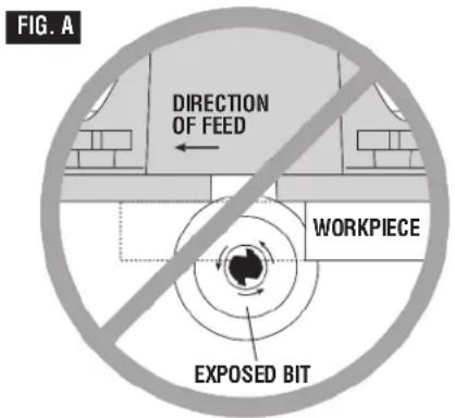
Improper Fence Location and Workpiece Feed
WARNING
Do not feed the workpiece where the majority of the workpiece is
between the fence and the bit. This creates a “fence trap” which is dangerous for two reasons:
- The front of the bit is exposed during the cutting operation (Fig. A).
- The bit can “Climb-cut,” where the bit enters the workpiece in the same direction as the feed direction. This is likely to cause the workpiece to “climb” away from the tabletop and may lead to loss of control during operation (Fig. A).
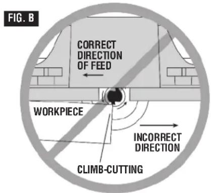
WARNING
Feed the workpiece only against the rotation of the bit. Do not
“back feed” the work into the bit. The bit rotates counterclockwise as viewed from the top of the table. “Back feeding” the work is dangerous for two reasons:
- It will cause climb-cutting where the workpiece can "climb" off the tabletop in the direction of the bit rotation, pulling the workpiece and possibly your hands into the rotating bit (Fig. B).
- It is difficult to keep the workpiece against the fence face as the bit rotation will push the workpiece away from the fence.
Important Information About Extension Cords
WARNING
An extension cord with adequate size conductors that is capable of rent for your tool must be used.
This will prevent excessive voltage drop, loss of power, or overheating. Grounded tools must use 3-wire extension cords that have 3-prong plugs and receptacles.
NOTE: The smaller the gauge number, the heavier the cord.
RECOMMENDED SIZES OF EXTENSION CORDS 120-VOLT ALTERNATING CURRENT TOOLS
| Tool's Ampere Rating | Cord Size in A.W.G. | Wire Sizes in mm^2 |
| Cord Length in Feet 25 50 100 150 15 | Cord Length in Meters 30 60 120 | |
| 3-6 | 18161614.75.751.52.5 | |
| 6-8 | 18161412.751.02.54.0 | |
| 8-10 | 18161412.751.02.54.0 | |
| 10-12 | 161614121.02.54.0— | |
| 12-16 | 1412————— |
Symbols
IMPORTANT: Some of the following symbols may be used on your tool. Please study them and learn their meaning. Proper interpretation of these symbols will allow you to operate the tool better and safer.
| Symbol Name | Designation/Explanation | |
| V Volts Voltage (potential) | ||
| A Amperes | Current | |
| Hz Hertz Frequency (cycles per second) | ||
| W Watt Power | ||
| kg Kilograms | Weight | |
| min | Minutes | Time |
| s | Seconds | Time |
| ∅ | Diameter | Size of drill bits, grinding wheels, etc. |
| no No load speed | Rotational speed, at no load | |
| .../min | Revolutions or reciprocation per minute | Revolutions, strokes, surface speed, orbits etc. per minute |
| 0 | Off position | Zero speed, zero torque... |
| 1, 2, 3, ...I, II, III, | Selector settings | Speed, torque, or position settingsHigher number means greater speed |
 | Infinitely variable selector with off | Speed is increasing from 0 setting |
| → | Arrow | Action in the direction of arrow |
| ~ | Alternating current | Type or a characteristic of current |
| --- | Direct current | Type or a characteristic of current |
| ~ | Alternating or direct current | Type or a characteristic of current |
| ☐ | Class II construction | Designates double-insulated construction tools |
| ⊕ | Earthing terminal | Grounding terminal |
| ⚠ | Warning symbol | Alerts user to warning messages |
 | Ni-Cad RBRC seal | Designates Ni-Cad battery recycling program |


This symbol designates that this tool complies to NOM Mexican Standards.

This symbol designates that this tool is listed by the Canadian Standards Association.

This symbol designates that this tool is listed by Underwriters Laboratories and listed to Canadian Standards by Underwriters Laboratories.

This symbol designates that components of this tool are recognized by Underwriters Laboratories and recognized to Canadian Standards by Underwriters Laboratories.
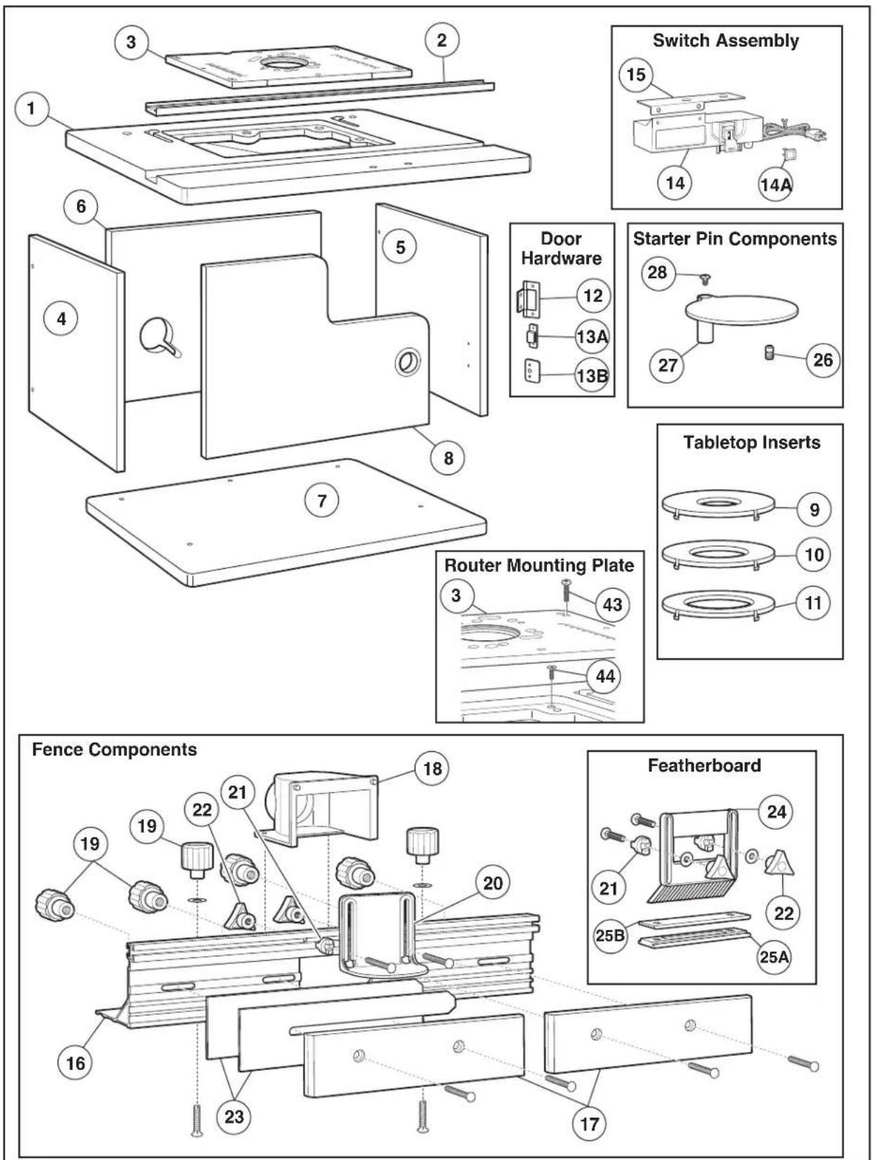
Parts List
Refer to Parts List below and on pages 8–10.

WARNING
are missing,
DO NOT attempt to assemble,
install, or use your router table until the missing parts have been found or replaced and your router table has been properly and correctly assembled per this manual.
- For missing parts or technical assistance, call 1-877-BOSCH99 (877-267-2499).
- In order to simplify handling and to minimize any damage that may occur during shipping, your router table comes mostly unassembled. Note that the switch box and some fasteners are preassembled to facilitate identification and installation.
- Separate all parts from the packaging materials and check each part against the illustrations and the parts lists to make sure that all parts have been included. Do this before discarding any of the packaging material.
| Key No. Description Quantity | ||
| ROUTER TABLE COMPONENTS | ||
| 1 Router Tabletop 1 | ||
| 2 Aluminum Miter Channel 1 | ||
| 3 Router Mounting Plate 1 | ||
| 4 Left Side Panel 1 | ||
| 5 Right Side Panel 1 | ||
| 6 Back Panel 1 | ||
| 7 Router Table Base 1 | ||
| 8 Router Table Door 1 | ||
| 9 Tabletop Insert w/ 1" dia. hole | 1 | |
| 10 | Tabletop Insert w/ 2" dia. hole | 1 |
| 11 | Tabletop Insert w/ 2 34 " dia. hole | 1 |
| 12 | Door Hinge (may be preinstalled on door) | 2 |
| 13A | Magnetic Door Catch | 1 |
| 13B | Door Catch Plate | 1 |
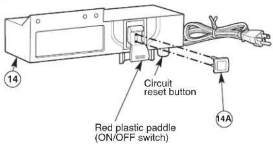
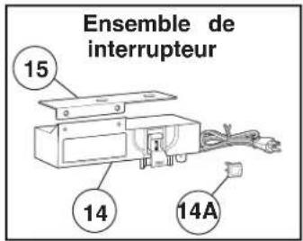
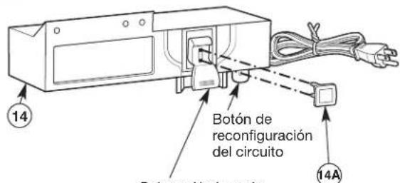
| 14 | Switch Box Assembly With Lockout Key | 1 |
| 14A | Lockout Key | 1 |
| 15 | Switch Mounting Bracket | 1 |
| FENCE COMPONENTS | ||
| 16 | Aluminum Fence 1 | |
| 17 | Fence Facing | 2 |
| 18 | Vacuum Port | 1 |
| 19 | Large Clamping Knob (in hardware bag) | 6 |
| 20 | Overhead Guard | 1 |
| 21 | Spacer (in hardware bag) | 6 |
| 22 | Small Clamping Knob (in hardware bag) | 6 |
| 23 | 1/16" Jointing Shim | 2 |
| 24 | Featherboard | 2 |
| 25A | Lower Featherboard Slide Plate | 1 |
| 25B | Upper Featherboard Slide Plate | 1 |
| STARTER PIN COMPONENTS | ||
| 26 | Starter Pin | 1 |
| 27 | Starter Pin Guard | 1 |
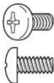
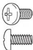
| 28 | #10-32 x 3/8" Truss-Head Phillips Machine Screw | 1 |
Parts List
Parts List
Key No. Description Quantity
| FASTENERS (FOR TABLE AND FENCE ASSEMBLY) | |
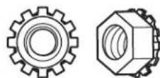
| 29 #10-32 KEPS Nut 9 | |
| 30 Small Washer 5 | |
| 31 Large Washer 6 | |
| 32 #10-32 Threaded Insert (may be preinstalled in tabletop) 8 | |
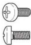
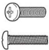
| 33 #10-32 x 1/2"Pan-Head Phillips Machine Screw 5 | |
| 34 #10-32 x 1 1⁄2"Pan-Head Phillips Machine Screw 2 | |
| 35 5/8"lg. Flat-Head Phillips Wood Screws † 15 | |
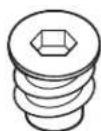
| 36 #10-32 x 1"Countersunk Phillips Machine Screw 3 | |
| 37 #10-32 x 5/8"Countersunk Phillips Machine Screw 2 | |
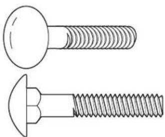
| 38 Allen-Head Connector Screw | 13 |
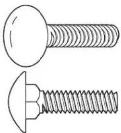
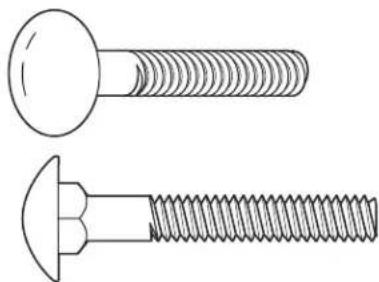
| 39 1/4-20 x 1"Carriage Bolt | 4 |
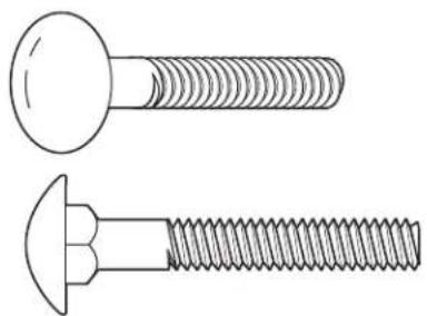
| 40 1/4-20 x 1 1⁄2"Carriage Bolt | 6 |
| 41 1/4-20 x 1 3⁄4"Carriage Bolt | 2 |
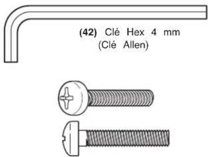
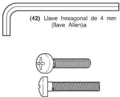
| 42 4mm Hex Key (Allen Wrench) | 1 |
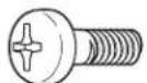
| 43 #10-32 x 1"Pan-Head Phillips Machine Screw | 4 |
| 44 #10-32 x 3/4"Countersunk Phillips Machine Screw 4 | |
FASTENERS (FOR MOUNTING ROUTERS)
| 31 Large Washer 4 | |
| 45 #10-32 x 1/2"Pan-Head Phillips Machine Screw 3 | |
| 46 1/4-20 x 1 1⁄2"Pan-Head Phillips Machine Screw | 4 |
| 47 #10-24 x 1/2"Pan-Head Phillips Machine Screw 4 | |
| 48 #8-32 x 1/2"Pan-Head Phillips Machine Screw | 3 |
| 49 1/4-20 KEPS Nut | 4 |
| 50 5/16-18 x 1/2"Pan-Head Phillips Machine Screw | 3 |
| 51 M4 x 20 Pan-Head Phillips Machine Screw | 3 |
†4 may be preinstalled on the hinges.
NOTE: The hardware bag contains fasteners for several models. Some fasteners may not be used in the assembly of this model. Refer to the parts list above for the correct sizes and quantities used with this table.


(29) #10-32 KEPS Nut


(30) Small Washer


(31) Large Washer
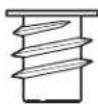
(32) #10-32 Leveling Insert
(33) #10-32 x 1/2" Pan-Head Phillips Machine Screw
(34) #10-32 x 1½" Pan-Head Phillips Machine Screw

(35) 5/8"Flat-Head Phillips Wood Screw
(36) #10-32 x 1" Countersunk Phillips Machine Screw
Parts List
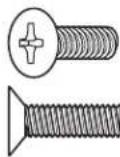
(37) #10-32 x 5/8" Countersunk Phillips Machine Screw
natural_image
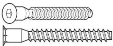
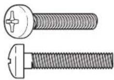
Technical line drawing of two different types of screw fasteners (no text or symbols)(38) Allen-Head Connector Screw
natural_image
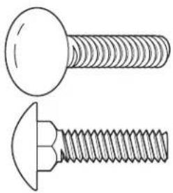
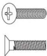
Technical line drawing of two screws (no text or symbols present)(39) 1/4-20 x 1" Carriage Bolt
natural_image
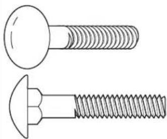
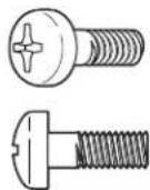
Technical line drawing of two types of screws (screw and nut) with threaded ends, no text or symbols present.(40) 1/4-20 x 1½" Carriage Bolt

natural_image
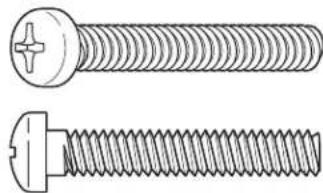
Technical line drawing of two types of screws (two and one) with threaded ends, no text or symbols present.(41) 1/4-20 x 1 ^3/4 "Carriage Bolt

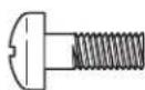
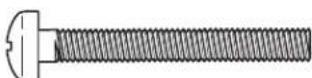
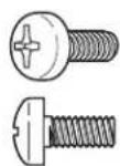
(43) #10-32 x 1"Pan-Head Phillips Machine Screw
(44) #10-32 x 3/4" Countersunk Phillips Machine Screw
(45) #10-32 x 1/2"Pan-Head Phillips Machine Screw
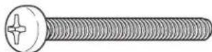
natural_image
Technical line drawing of a two-pin screw with threaded end (no text or symbols)(46) 1/4-20 x 1 ½"Pan-Head Phillips Machine Screw
(47) #10-24 x 1/2"Pan-Head Phillips Machine Screw
(48) #8-32 x 1/2"Pan-Head Phillips Machine Screw
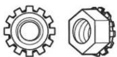
(49) 1/4-20 KEPS Nut
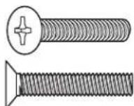
natural_image
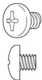
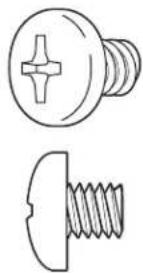
Technical line drawing of two screw components: a circular head with cross-shaped end and a straight threaded base (no text or symbols)(50) 5/16-18 x 1/2" Pan-Head Phillips Machine Screw
(51) M4 x 20 Pan-Head Phillips Machine Screw
Router Table Assembly
ASSEMBLING THE ROUTER TABLE
HELPFUL TOOLS
-
1 and #2 Phillips screwdrivers (not included)
- 3/8" wrench or nutdriver (not included)
- 4mm hex key (included)
HINT: Applying bar soap or beeswax to the screw threads (35 and 38) will make them easier to install into the panels.
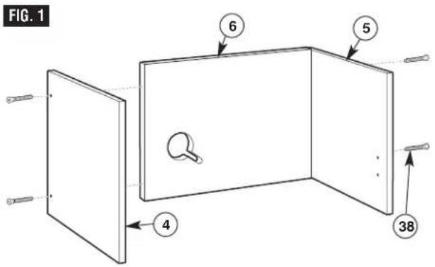
ASSEMBLE SIDES TO BACK (Fig. 1)
NOTE: The mounting holes for the left and right panels are spaced so that the panel will only fit on the correct end of the back. Before attaching the panels, make sure that the predrilled holes for the hinges and door catch are on the INSIDE surface of the panel.
- Holding the back panel (6) upright, with the cord cutout on the left (see Fig. 1), attach the left side panel (4) to the back panel using two Allen-head connector screws (38).
- Attach the right side panel (5) to the back panel using two Allen-head connector screws (38).
- Tighten all fasteners securely with the 4mm hex key (42). The screw head will stand slightly above the panel surface. DO NOT OVERTIGHTEN!
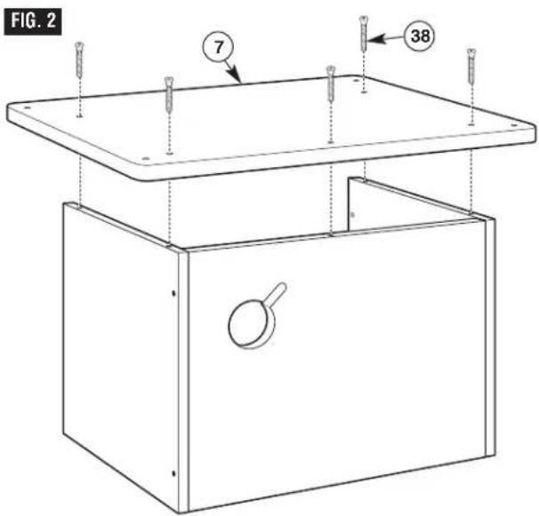
ATTACHING THE BASE (Fig. 2)
- Turn the sides/back assembly upside down, and position the base (7), with countersunk holes on the base facing out, on the sides/back.
- Align the holes in the base with the holes in the sides and back, and attach using five Allen-head connector screws (38) (Fig. 2).
- Tighten all fasteners securely with the 4mm hex key (42). The screw head should be in the counterbore, below the panel surface. DO NOT OVERTIGHTEN!
Router Table Assembly
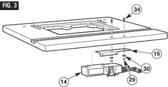
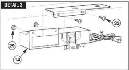
ATTACHING THE SWITCH TO THE TABLETOP (Fig. 3)
Assembly Hint: It may be easier to attach the switch bracket if you stand the tabletop on its back edge for this step.
- Align the two holes in the switch mounting bracket (15) with the two through-holes in the router tabletop. From the top side of the table, insert two #10-32 x 1½"pan-head machine screws (34) through the tabletop and bracket and secure the bracket in place with two small washers (30) and two #10-32 KEPS nuts (29) (Fig. 3).
- Insert two #10-32 KEPS nuts (29) into the hex-shaped recesses in the back of the switch assembly (14) with the toothed washer facing away from the recess. Secure the switch to the switch mounting bracket with two #10-32 x 1/2 "pan-head machine screws (33) while holding the KEPS nuts in place in the recess with your finger.
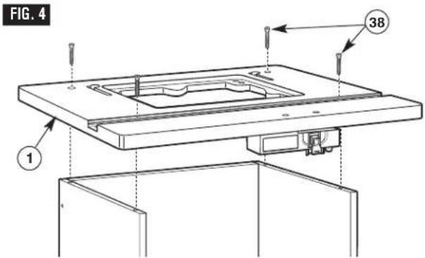
ATTACH THE TABLETOP (Fig. 4)
NOTE: The tabletop may be shipped with the miter channel in place. To access the tabletop mounting holes, remove the channel for this step.
- With the base assembly upright, position the tabletop (1) on the base assembly, making sure the switch is in the front, as shown in Fig. 4.
- Secure the tabletop to the base with four Allen-head connector screws (38).
- Tighten all fasteners securely with the 4mm hex key. The screw head should be in the counterbore, below the panel surface. DO NOT OVERTIGHTEN!
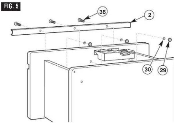
ASSEMBLE THE ALUMINUM MITER CHANNEL TO THE TABLETOP (Fig. 5)
Assembly Hint: It may be easier to install the miter channel if you lay the table on its back for this step.
- Center the miter channel (2) in the slot on the tabletop; then press the miter channel into the slot.
- From the top side of the tabletop (1), insert three #10-32 x 1" countersunk Phillips machine screws (36) through the holes in the miter channel (2) and the tabletop (Fig. 5).
- Secure with a small washer (30) and a #10-32 KEPS nut (29) on each screw.
Router Table Assembly
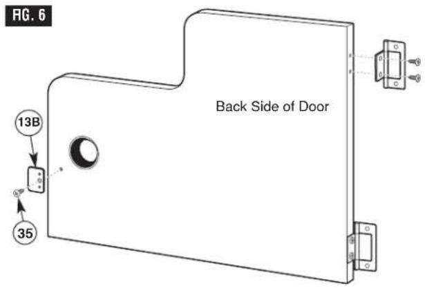
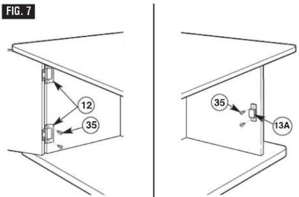
ATTACH THE DOOR (Figs. 6 and 7)
HINT: Applying bar soap or beeswax to the screw threads will make them easier to install into the panels.
- With the bumps on the catch plate against the door surface, attach the metal catch plate (13B) to the inside of the narrow end of the door with a 5/8 "lg. flat-head Phillips wood screw (35). To help align the catch plate, the bumps should rest in the top and bottom holes on the door (Fig. 6).
- Attach the door hinges (12) to the left side panel with two 5/8"lg. flat-head Phillips wood screws (35) on each hinge (Fig. 7).
- Attach the magnetic catch (13A) to the inside of the right side panel using two 5/8 "lg. flat-head Phillips wood screws (35) (Fig. 7).
- Slowly open and close the door, making sure that it moves freely and does not rub on the base or top, does not come in contact with the switch assembly, and that it latches correctly.
- If the door rubs, make sure the side panels and switch are assembled correctly.
- If the magnetic catch does not contact the catch plate, loosen the screws on the magnetic catch and reposition it using the slotted holes in the catch.
Router Table Assembly
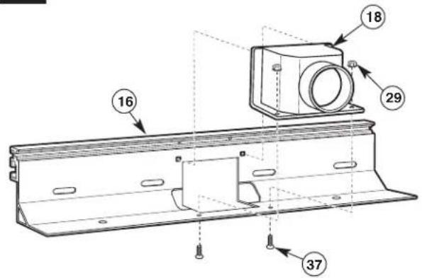
ASSEMBLING THE FENCE
ASSEMBLING THE FENCE (Figs. 8 and 9)
- Insert the pins molded into the top of the vacuum port (18) into the holes on the rear of the aluminum fence (16), as shown in Fig. 8.
- From the underside of the fence, insert two #10-32 x 5/8"countersunk machine screws (37) up through the holes in the bottom of the fence and vacuum port. Secure in place with two #10-32 KEPS nuts (29) (Fig. 8).
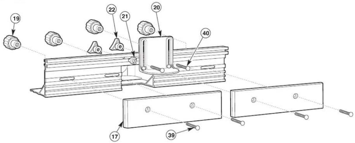
- Place the fence right-side up on a flat surface and align the counterbored holes in the fence facings (17) with the slotted holes in the fence. The counterbored side of the facings should face OUT (Fig. 9).
- Attach both fence facings (17) to the front of the fence, using two 1/4-20 x 1'carriage bolts (39) and two large clamping knobs (19) for each fence facing (Fig. 9).
- From the front of the overhead guard (20), insert two 1/4-20 x 1½" carriage bolts (40) through the holes in the guard. Slide a spacer (21) on each bolt so that the tabs on the spacers fit into the slots on the guard (Fig. 9).
- From the front of the fence, insert the carriage bolts through the holes in the top center of the fence. The tabs on the spacers will fit into the top channel on the fence. Secure in place with a small clamping knob (22) on each bolt (Fig. 9).
NOTE: To simplify installation of the router adapter plate and router, do not install the fence onto the router table at this time.
FIG. 8
NOTE: Two plastic jointing shims (23) are included to provide the proper fence offset when jointing. For more about jointing operations and shim placement, see page 28.
natural_image
Simple line drawing of two overlapping rectangular shapes with no text or symbolsFIG. 9

Router Table Assembly

Before using the router table, verify that the router is securely clamped to the router table base. While working, periodically check the router base fasteners clamping tightness.
Router motor vibration can loosen fasteners during use, causing the router to fall from the table.
SELECTING THE ROUTER HOLE PATTERN
DETERMINE THE MOUNTING METHOD TO BE USED (see chart on page 16)
If your router model is listed in the chart on page 16, proceed to step 1 below. If it is NOT listed, you must purchase a BOSCH RA1186 Router Adapter Plate, available separately.
If your router model is listed:
- Determine the hole pattern that matches the mounting hole pattern for your router.
- Determine which fasteners you will need to attach the router to the router adapter plate.
- Determine which mount type (1 or 2) is used for your router model.
MOUNT TYPE 1
MOUNT TYPE 2
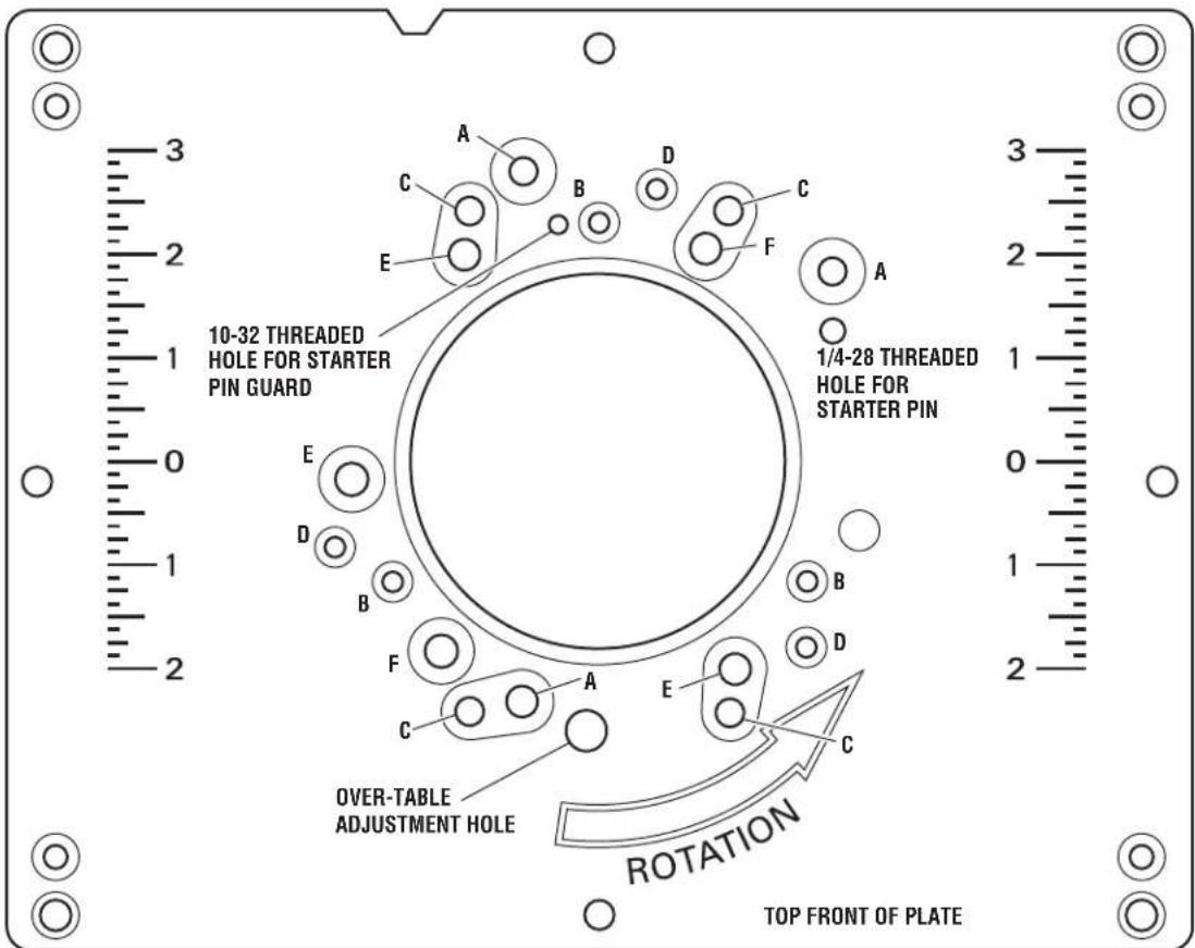
MOUNTING PLATE GUIDE FOR COMPATIBLE ROUTERS (Fig. 10)
FIG. 10
Router Table Assembly
CHART 1
| Router Router Hole Fasteners Brand Model Pattern Required Type | ||||
| Bosch 1613 series A 1/4-20 x 1 | 12 "Pan-head Phillips machine screws (46), 2 washers (31), and 1/4-20 nuts (49) | |||
| Bosch | 1617 series (fixed base models only) | B | #10-24 x 1/2" Pan-head Phillips machine screws (47) | 1 |
| Bosch | MR series | B | M4 x 20 Pan-head Phillips machine screws (51) | 1 |
| Craftsman | Most Craftsman 1/2"collet routers | E | 5/16-18 x 1/2" Pan-head Phillips machine screws (50) | 1 |
| DeWalt | DW616, DW618 (fixed base only) | B | #8-32 x 1/2" Pan-head Phillips machine screws (48) | 1 |
| Hitachi | M12VC | B | #10-32 x 1/2" Pan-head Phillips machine screws (45) | 1 |
| Makita | RF1100, RF1101 | B | #10-24 x 1/2" Pan-head Phillips machine screws (47) | 1 |
| Milwaukee | 5615, 5616 | B | #10-24 x 1/2" Pan-head Phillips machine screws (47) | 1 |
| Porter-Cable | 690 series, 7529 plunge router, and 892-895 series (fixed base only) | B | #10-24 x 1/2" Pan-head Phillips machine screws (47) | 1 |
| Ryobi | R161, R162, R163 | E | 5/16-18 x 1/2" Pan-head Phillips machine screws (50) | 1 |
| Ryobi | RE170, RE180 PL | F | 5/16-18 x 1/2" Pan-head Phillips machine screws (50)* | 1 |
| Skil | 1810, 1815, 1820, 1825 | D | #10-32 x 1/2" Pan-head Phillips machine screws (45) | 1 |
*RE170 requires the subbase attached for specified fastener length.
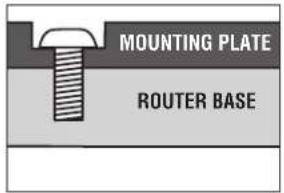
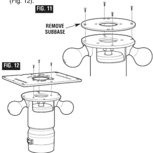
ATTACH ROUTER TO MOUNTING PLATE (Figs. 11 and 12)
WARNING
Disconnect the router from the power supply before installing
router into the table, making adjustments, changing accessories, removing the router from the table, performing maintenance, or storing the tool. Such precautionary safety measures reduce the risk of unintentional tool operation.
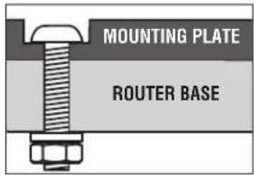
- Remove the plastic subbase from your router (unless otherwise specified in Chart 1) (Fig. 11).
-
If you wish to mount the router with the subbase, you may need to purchase longer fasteners. Using the subbase affects the range of cutting depth.
-
If your router has its own dust extraction hood that mounts to the top of the metal router base and you want to use it under the router table, this is a convenient time to install it.
-
Using Chart 1, determine the hardware and mount type for your router.
- For most router models, the screws are driven into threaded holes in the router's base (mount type 1).
- For some router models, the screws go all the way through the base and are fastened with washers and nuts (mount type 2).
- Competitor routers are outside of BOSCH's control. Changes made to these routers may affect the compatibility to the fasteners specified and/or supplied with this table.
- Always make sure the screw is fully seated on the adapter plate and that the router base is firmly against the adapter plate to ensure secure mounting. If the router, plate, and fasteners do not seat together properly, you may need to purchase new fasteners of a different length or size.
WARNING Before using the router table, verify that the router is securely clamped to the router table base. While working, periodically check the router base fasteners' clamping tightness. Router motor vibration can loosen fasteners during use, causing the router to fall from the table.
-
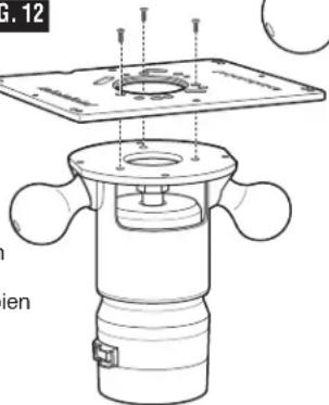
Refer to the mounting plate guide (Fig. 10) on page 15 and align the appropriate mounting plate holes for your router to the router base holes. Make sure that the depth adjustment controls on the router face the front of the mounting plate. Figure 10 shows the proper orientation of the plate when installed on the table.
-
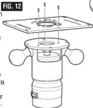
Securely mount your router to the mounting plate (Fig. 12).
Router Table Assembly
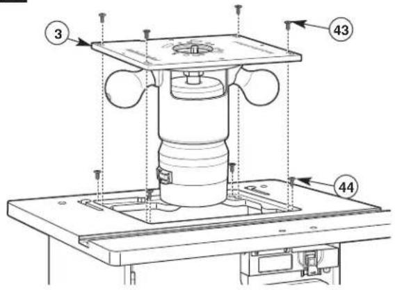
ATTACH THE ROUTER MOUNTING PLATE (Fig. 13)
-
If the fence is already installed on the table, remove it before proceeding.
-
Install the four countersunk leveling screws (44) in the tabletop with a Phillips screwdriver and gently tighten them. Place the router mounting plate (3) on the leveling screws with the number scales right-side up as seen from the front of the table (Fig. 13). Using the Phillips screwdriver and a straight edge, adjust the leveling screws through the holes in the router mounting plate until the top of the plate is flush with the table surface. Turning the screws clockwise will lower the mounting plate and turning them counterclockwise will raise it.
-
Secure the router mounting plate (3) to the table with four #10-32 x 1"pan-head screws (43) (Fig. 13) through the innermost corner holes in the plate. Tighten the screws snugly, but do not overtighten.
FIG. 13
TO REMOVE THE ROUTER AND/OR ROUTER MOUNTING PLATE
WARNING
Make sure that the router is NOT plugged into a power outlet when installing into the table, removing from table, making adjustments or changing accessories. Router could accidentally start.
THE FENCE MUST BE REMOVED FROM THE ROUTER TABLE WHEN REMOVING OR REINSTALLING THE ROUTER MOUNTING PLATE.
To remove the router without removing the mounting plate, see step 3.
-
Remove the four #10-32 x 1" pan-head Phillips machine screws (43) holding the router mounting plate to the tabletop (Fig. 13).
-
Lift the router mounting plate and router upwards from the tabletop.
-
Remove the pan-head Phillips machine screws securing the router to the mounting plate.
-
When reinstalling the router mounting plate, be sure that the plate is level with the tabletop. If needed, readjust as described above.
OVER-TABLE HEIGHT ADJUSTMENT
The router adapter plate features an access hole to allow use with the over-table height adjustment feature on the BOSCH 1617 series routers. Refer to your router manual for additional information on using this feature.
For other brands of routers with over-table height adjustment features, it may be necessary to drill an access hole in the router mounting plate as follows:
-
Remove the subbase from the router and align the mounting holes in the subbase with the corresponding mounting holes in the adapter plate. Be sure to orient the subbase so that the router switch will be toward the front of the table.
-
Using a pencil or centerpunch, mark the location of the over-table height adjustment hole on the router adapter plate.
-
Remove the subbase from the adapter plate and carefully drill the over-table height adjustment hole.
-
Make sure that the hole will accommodate the height adjustment tool for your router. Remove any burrs or rough edges with sandpaper.
Router Table Assembly
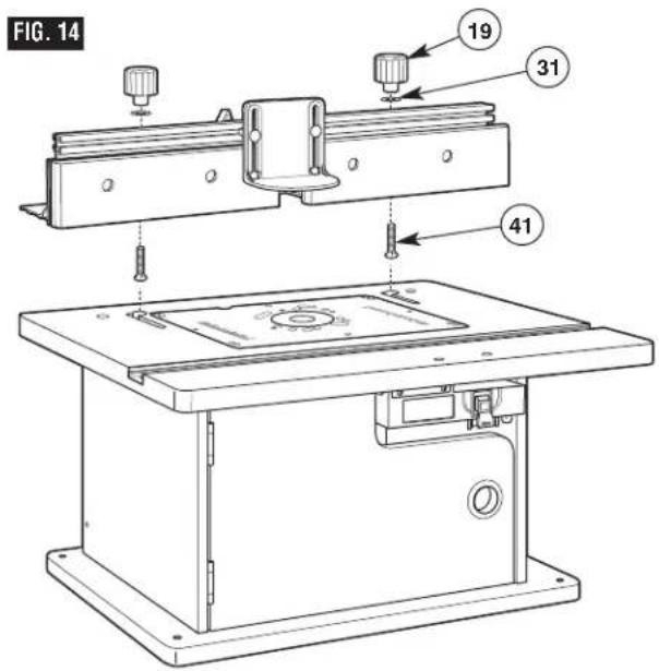
ATTACHING THE FENCE TO THE TABLE (Fig. 14)
- From underneath, slide two 1/4-20 x 1 3/4" carriage bolts (41) up through the holes in the bottom of the fence. Slide a large washer (31) onto each bolt and loosely attach a large clamping knob (19) onto each bolt.
- Insert the carriage bolt heads through the holes of the J-slots on the tabletop, making sure the bolt head is below the inside surface of the tabletop and can slide freely into the J-slot.
- Slide the fence assembly left and into the J-slot and make sure that it slides smoothly from front to back.
NOTE: Use the scale on the tabletop as a guide when aligning the fence for routing operations. Once the fence is positioned and aligned correctly, tighten the clamping knobs SECURELY.
WARNING
Before operating, make sure
the entire unit (table with router
installed) is placed on and secured to a solid, flat, level surface and will not tip. Use of auxiliary in-feed and out-feed supports is necessary for long or wide workpieces. Long workpieces without adequate support can cause the router table to tip over.
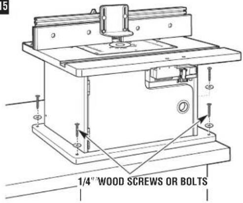
SECURING THE ROUTER TABLE TO A WORK SURFACE (Fig. 15)
Preferred method:
The base of the router table has four mounting holes. These holes can be used to attach it to a workbench or work surface with four 1/4 "wood screws and washers or bolts, washers, and nuts (not provided).
HINT: Position the router table in the desired location and mark the hole locations using the holes in the table base. Then drill suitable pilot (for wood screws) or through-holes (for bolts).
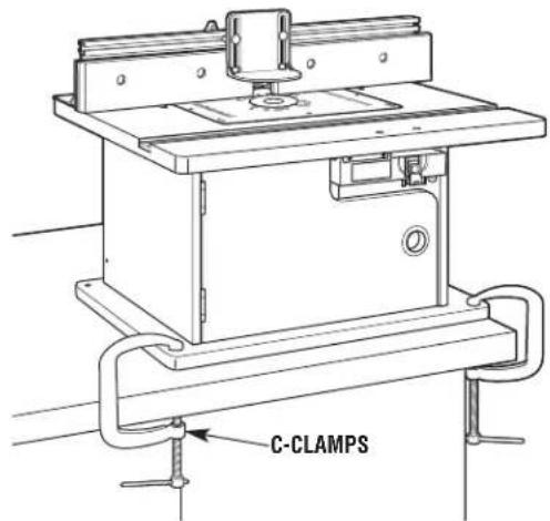
Alternative method:
The base can be secured to a workbench or work surface with C-clamps.
FIG. 15
OR
Router Table Assembly
WARNING
Disconnect the router from the power supply before installing
router into the table, making adjustments, changing accessories, removing the router from the table, performing maintenance, or storing the tool. Such precautionary safety measures reduce the risk of unintentional tool operation.
WARNING
Do not alter tabletop insert ring or insert plate bit hole. Match the
cutting diameter of the bit to the inner diameter of the insert ring or insert plate bit hole such that the difference is no less than 1/16 on a side. Insert rings are meant to reduce the gap between the cutting diameter of the bit and table so that workpieces maintain full support of the table while routing.
TABLETOP INSERT RINGS (Fig. 16)
This router table includes three insert rings with the following hole sizes:
(9) 1" in diameter, for use with bits with diameters up to 7/8"
(10) 2" in diameter, for use with bits with diameters up to 1 78 "
(11) 2^3/4 " in diameter, for use with bits with diameters up to 2^5/8 "
No insert ring is used for bits with diameters over 258 " and up to 312 ".
! WARNING
Do not use the router table with bits over 312 " in diameter. Bits
larger than 3½" exceed the clearance hole in the tabletop insert rings. Bits larger than 3½" can contact insert plate or insert ring, throwing fragments.
FIG. 16
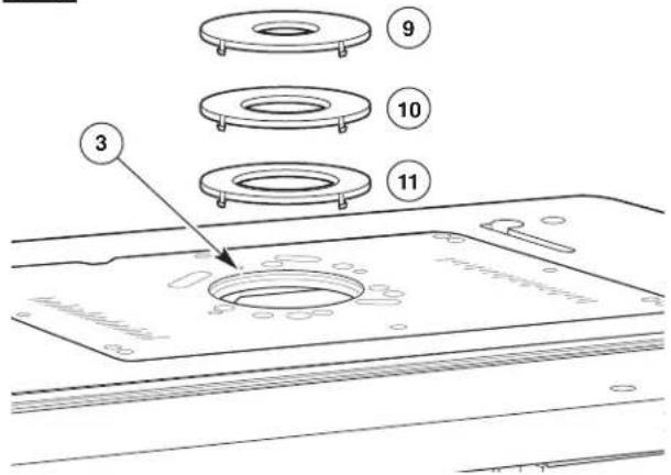
TO INSTALL TABLETOP INSERT RINGS
(Fig. 16):
- Select the insert ring (9–11) that best accommodates the router bit to be used.
- Press the insert ring (9–11) into the large hole in the router mounting plate (3). If the fence is in the way, loosen the clamping knobs on the fence and slide the fence back out of the way.
- Press down evenly over the tabs until the insert ring (9–11) locks into place.
- To remove, pull up gently until the tabs disengage. When not in use, store insert rings (9–11) in a resealable plastic bag in the router table cabinet.
WARNING
Do not use, attempt to change, or remove tabletop insert rings from
the tabletop unless the router is off and unplugged. Such precautionary safety measures reduce the risk of unintentional tool operation.
Router Table Operation
SWITCH CONTROL BOX
WARNING
Do not plug router motor power cord into standard wall outlet. It
must be plugged into the router table switch. Power tool switches and controls need to be within your reach in emergency situations.
GENERAL INFORMATION
The power switch is designed for use with most BOSCH Router Tables. It provides the convenience of an ON (RESET)-OFF switch at the front of the table, thus eliminating the need to reach underneath the table to turn the router ON and OFF.
The power switch also provides an optional simultaneous ON-OFF control of an additional accessory, such as a light, wet/dry vac, etc. The switch has an internal, resettable circuit breaker to provide overload protection.
ELECTRICAL REQUIREMENTS
The switch box cord should only be plugged into a 14-gauge (or heavier), three-wire extension cord with a three-hole grounding receptacle and three-prong grounding plug. The extension cord must be plugged into a matching outlet that has been installed by a licensed electrician and grounded in accordance with all local codes and ordinances.
DAMAGED OR WORN EXTENSION CORDS ARE NOT TO BE USED AND ARE TO BE REPLACED IMMEDIATELY.
The electrical outlets at the back of the switch box will accept three-hole extension cords.
The electrical receptacles at the back of the switch box will accept either three-prong or two-prong plugs from a router or accessory.
In the event of a malfunction or breakdown, grounding provides the path of least resistance for electrical current in order to reduce the risk of electrical shock. This switch box is equipped with an electrical cord that has an equipment-grounding connector and a grounding plug.
DO NOT modify the plug from the switch if it does not plug into the extension cord. Obtain an extension cord with the proper outlet.
Improper connection of the equipment-grounding conductor can result in risk of an electrical shock.
The conductor with insulation that has a green outer surface, with or without yellow stripes, is the equipment-grounding conductor.
DO NOT CONNECT THE EQUIPMENT-GROUNDING CONDUCTOR TO A LIVE TERMINAL.
Check with a licensed electrician if the grounding instructions are not completely understood, or if there is doubt as to whether the electrical outlet or extension cord is properly grounded.
WARNING
Do not permit fingers to touch terminals of the plug when inserting plug from the outlet. Risk of Electric
WARNING
Use the switch box only when properly assembled to the router with a router that has also been used on a properly assembled router cautionary safety measures reduce the loss of control.
WARNING
Do not exceed a total combined rating of 15 amps when connecting my accessories such as a light or . The switch has a rating of 15 amps.
Router Table Operation
CONNECTING THE ROUTER POWER CORD TO THE SWITCH
! WARNING
Before connecting router to router table switch box, ensure that the router switch is OFF, and that the router table switch box is unplugged. Such precautionary safety measures reduce the risk of unintentional tool operation.
- Plug the router power cord into one of the electrical outlets on the back of the switch case (14).
- Form the excess power cord into a coil.
- Wrap two pieces of friction tape or strong cord around the coiled cord at opposite sides of the coil.
- Allow some slack so that the cord does not become stretched when it is plugged into the switch box outlets.
- If desired, at this time plug the power cord from an accessory, such as a wet/dry vac or light, into the other outlet.
WARNING
Before starting to work, ensure that the power cords from the router, accessories, the switch case, and the extension cord do not and cannot come in contact with the router or any moving parts of the router. Such precautionary safety measures reduce the risk of injury due to loss of control.
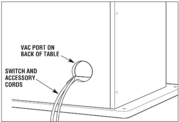
Cord Routing
Route the switch cord and any accessory power cords through the notch in the vacuum port on the back of the router table cabinet.
Router Table Operation
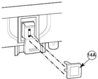
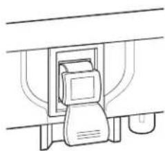
This section explains the operation and features of the switch box assembly prior to plugging the power cord into a power outlet. The intent is to familiarize the user with the switch operation without actually turning ON the router.
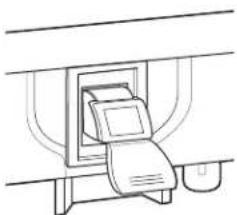
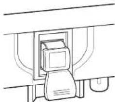
The switch box (14) (Fig. 17) incorporates a lockout key (14A) to help prevent unauthorized use by others.
- The lockout key (14A) is the yellow part in the top of the red plastic paddle. The yellow lockout key must be completely inserted into the top of the red plastic paddle and switch box (14) before the paddle can be turned ON.
- The circuit reset button for the switch box (14) is on the bottom right side of the box.
WARNING
Make sure that the extension cord is not plugged into an electrical
outlet before proceeding any further.
- Make sure the yellow lockout key (14A) is completely inserted in the top of the red plastic paddle.

- To turn the router ON, lift the red plastic paddle up to the ON position.
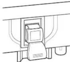
- To turn the router OFF, press the red plastic paddle to the OFF position.
natural_image
Line drawing of a printer emitting a paper airplane into a container (no text or symbols)ON (UP)
natural_image
Simple line drawing of a mechanical device with no text or symbolsOFF (DOWN)
FIG. 17
- To prevent unauthorized use, the switch can be disabled by removing the yellow lockout key (14A) completely from the top of the red plastic paddle.
Router Table Operation
WARNING
Before proceeding any further, make sure the switch on the router sition and the switch lever is in the
is in the OFF position and the switch lever is in the OFF position.
WARNING
Never leave the router unattended while it is running or before it plete stop.
comes to a complete stop.
WARNING
Before starting to work ensure that the power cords from the
router, accessories, the switch case, and the extension cord do not and cannot come in contact with the router or any moving parts of the router. Such precautionary safety measures reduce the risk of injury due to loss of control.
The switch power cord can now be plugged into the extension cord.
ROUTER AND SWITCH OPERATION
This section explains operation of the switch with the power cord plugged into the extension cord.
The router will turn ON when the red paddle on the switch box is pulled up to the ON position.
- Position the ON/OFF switch on the router in the ON position. On certain routers this will require the use of the switch trigger and "LOCK-ON" button. (Consult router owner's manual.) Make sure the switch on the switch box is in the OFF position when doing this.
- To turn the router ON, pull up the red paddle to the ON position. See page 22.
- To turn the router OFF, press the red paddle to the OFF position. See page 22.
CIRCUIT RESET BUTTON
NOTE: In the event of an overload, the internal switch circuit breaker will trip the switch to the OFF position. This will interrupt power to the router and any accessory plugged into the switch itself. If this occurs, proceed as follows:
- Push the red plastic paddle to the OFF position and unplug the switch cord from the wall outlet or extension cord.
- Turn router switch to OFF position.
- Remove the workpiece from the router table.
- Correct the cause of the overload situation. For example, if too many accessories are plugged into the switch, or combined amperage exceeds the switch rating, remove the accessory. Other causes include the removal of too much stock or use of too high a feed rate.
- Press the circuit reset button on the bottom of the switch box.
- Plug the switch power cord into the wall outlet or extension cord.
- Restart the router as described in the section ROUTER AND SWITCH OPERATION on this page.
WARNING
If the switch case does not work and you have tried to RESET the circuit
reset button as described above:
•Unplug ALL electrical connections.
- Remove the switch from the router table and obtain a replacement switch by calling BOSCH customer service at 1-877-BOSCH99.
WHEN THE ROUTER TABLE IS NOT IN USE
- Make sure the switch is in the OFF position.
- Remove the lockout key (14A). See page 22.
- Store the lockout key in a safe location where it is not available to children and other unauthorized persons.
- To turn the router ON, pull up the red paddle to the ON position. See page 22.
- Remove the router bit from the router.
- Position the router collet assembly below the top of the router table.
NOTE: If the key should become lost or damaged, replacement keys are available by calling BOSCH customer service at 1-877-BOSCH99.
Router Table Operation
ATTACHING AND USING A WET/DRY VACUUM
WARNING
Before connecting vacuum to router table switch box, ensure that the vacuum switch is OFF, and that the router table switch box is unplugged. Such precautionary safety measures reduce the risk of unintentional tool operation.
WARNING
Do not exceed a total combined rating of 15 amps when connecting the router and any accessories such as a light or wet/dry vacuum. The switch has a rating of 15 amps.
This router table features two vacuum ports for the attachment of a wet/dry vac with a 2 12 "nozzle. Select which port will provide optimal results, based on your routing operation:
- For routing operations where shavings and dust are typically pulled down under the tabletop, such as grooving, use the slotted hole in the back of the table cabinet. This will help prevent a buildup of sawdust and wood chips in the cabinet. To attach, simply push the nozzle into the port.
- For routing operations where sawdust and wood chips are ejected onto the tabletop, such as many edge-cutting operations, use the vacuum port on the back of the fence. To attach, simply push the nozzle into the port while holding the fence assembly in place.
The vacuum can be plugged into the router table switch and the cord routed through the slot in the vacuum port on the back of the cabinet. Be sure the cord does not interfere with router operation.
CAUTION
Operating the router table without a wet/dry vacuum can result in an excessive buildup of sawdust and wood chips under the fence assembly and guard, reducing the performance of the router table and fence assembly.
RECOMMENDATION: To maximize performance, regardless of whether a wet/dry vac is being used, remove the sawdust and wood chips from the cabinet and from under the fence assembly and guard as needed.
RECOMMENDATION: It is always a good practice to keep the work area clean. As necessary, remove any accumulated sawdust and wood chips from the top of the router table, as well as from the surrounding work area and floor.
WARNING
Never place your fingers near a spinning bit or under the guard when the router is plugged in. Such precautionary safety measures reduce the risk of personal injury.
INSTALLING THE ROUTER BIT (CUTTER)
WARNING
Disconnect the router from the power supply before making
adjustments or changing accessories. Such precautionary safety measures reduce the risk of unintentional tool operation.
Install the router bit according to the instructions included with your router. Because of the large variation of router bits, certain router bits may not always operate in the desired manner with this router table.
To ensure that the most popular bits will perform satisfactorily, install the bit so that the router collet engages 3/4" of the router bit shank. If the shank of the router bit bottoms out in the collet, back out the router bit approximately 1/16" to allow for proper tightening.
NEVER INSTALL ROUTER BITS WITH LESS THAN 3/4" OF SHANK ENGAGEMENT IN THE COLLET.
Router Table Operation
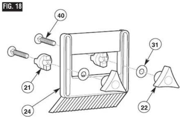
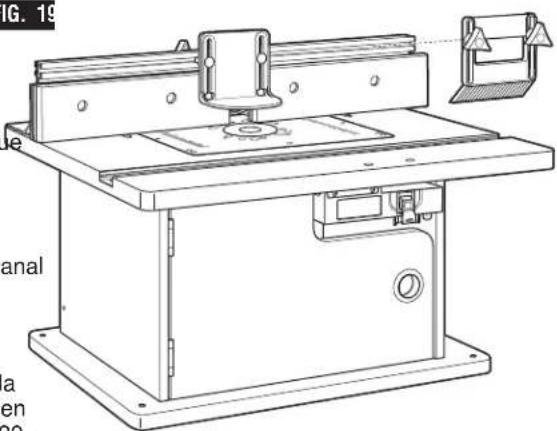
ASSEMBLING THE FEATHERBOARDS (Figs. 18–20)
NOTE: The top/front side of each featherboard is marked to indicate proper feed direction.
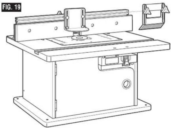
Fence Featherboard (Figs. 18 and 19)
- Insert two 1/4-20 x 1 ½" carriage bolts (40) through the slotted holes in the featherboard (24). See Fig. 18.
- Slide a large washer (31) onto each carriage bolt and thread a small clamping knob (22) three or four turns onto each carriage bolt.
- To install on the fence, slide a spacer (21) over the head of each carriage bolt, aligning the tabs on the spacer with the slot in the featherboard (Fig. 19). Then slide the carriage bolt heads into the T-slot on the top of the fence.
- Secure the featherboard assembly by tightening the knobs, making sure that the tabs on the spacer are in the slot on the fence.
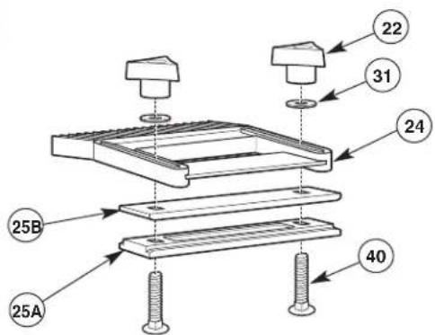
Tabletop Featherboard (Fig. 20)
NOTE: The featherboard slide plate assembly is T-shaped for use in the miter channel and has round indentations on the bottom for the carriage bolt heads.
- Insert two 1/4-20 x 1 ½" carriage bolts (40) through the holes in both the lower (25A) and upper (25B) featherboard slide plate and the slotted holes in the featherboard (24) as shown in Fig. 20.
- Slide a large washer (31) onto each carriage bolt and thread a small clamping knob (22) three or four turns onto each carriage bolt.
- To install the featherboard in the miter channel, insert the featherboard slide plate into the miter channel. Then slide the featherboard to the desired location on the miter channel and tighten the clamping knobs.
natural_image
Technical line drawing of a machine tool with base plate and workpiece (no text or symbols)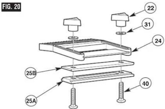
Router Table Operation
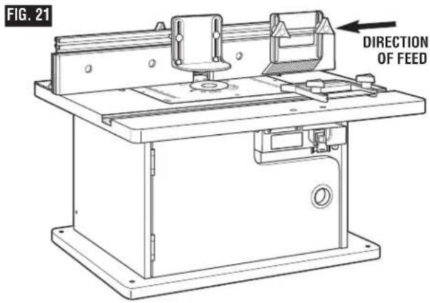
ROUTING USING FEATHERBOARDS (Fig. 21)
Featherboards are helpful in controlling the workpiece while routing and assist in keeping the workpiece flat on the tabletop. The tabletop featherboard, combined with the fence featherboard, helps keep the workpiece pressed against the fence and tabletop. The best location for the featherboards varies according to your application, workpiece size, and other factors.
- Loosely install the featherboard(s) as described on page 25.
- Place the workpiece on the router table so that it is squarely against the fence.
- Position both featherboards snugly against the workpiece and tighten the clamping knobs.
- The workpiece should move with some resistance but without requiring a great effort.
- For wider workpieces, the tabletop featherboard cannot be used. The second featherboard may also be positioned on the fence, if desired.
Additional featherboards, model RA1187, can be purchased from your Bosch retailer.
WARNING Never let go of the workpiece when routing until the cut has been completed and the workpiece is completely clear of the bit. Such precautionary safety measures reduce the risk of personal injury and/or property damage.
- Featherboards aid in holding the workpiece in position when routing on a router table.
•They are NOT intended to hold the workpiece in place alone when the workpiece is in contact with the bit, or at any other time when the bit is turning.
WARNING For accuracy in routing and improved control, the workpiece should be held against the router table fence when routing.
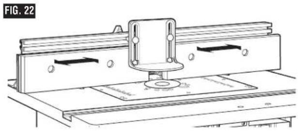
ADJUSTING THE FENCE FACING (Fig. 22)
The right and left fence facings are attached to the front face of the router table fence and can be adjusted inward or outward from the router bit to allow proper clearance for different-sized bits. To provide the best support during routing operations, the fence facings should be as close to the bit as possible without being able to come in contact with the bit (typically about 1/4" from the bit is a suitable distance).
- Loosen the two clamping knobs on the backs of the fence facings and slide the facings inward or outward from the router bit as needed.
natural_image
Technical line drawing of a mechanical assembly with mounting brackets and a central component (no text or symbols)WARNING Always hold the workpiece against the router table fence when routing.
Such precautionary safety measures increase the accuracy in routing and improve the control of the workpiece, reducing the risk of personal injury.
- Once the fence facings are in the desired position, tighten the clamping knobs SECURELY.
Router Table Operation
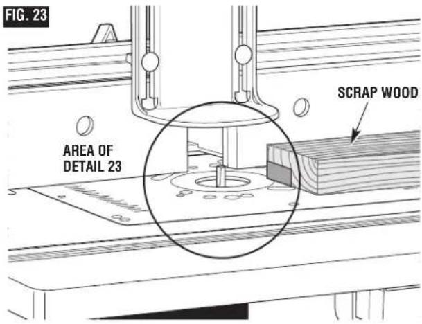
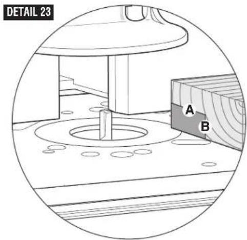
ADJUSTING DEPTH AND HEIGHT OF CUT (Fig. 23)
- Select a board that is smooth and straight, with good square edges.
- Mark lines "A" and "B" on the end of the board, as shown in Detail 23.
•Line "A" indicates the desired height of cut.
•Line "B" indicates the desired final depth of cut.
- The area outlined by "A," "B," and the edge of the board is the area that will be cut away.
- Following the instructions that came with your router, adjust the router height of cut until the top of the router bit lines up with line "A."
- If the desired depth of cut can be cut in a single pass, loosen the fence clamping knobs and move the fence forward or backward until the outermost cutting edge of the router bit is aligned with line "B." It may be necessary to reposition the guard to provide clear access.
NOTE: For deeper cuts, do NOT attempt to make the cut in a single pass. Make multiple shallower passes, progressively moving the fence backward until the desired depth of cut is reached.
- Use the scales on the table top as a guide to align the fence; then SECURELY tighten both fence clamping knobs.
WARNING
Always make sure that the fence and guard cannot come in contact
with the router bit. Failure to do so will result in damage to the router table and can cause personal injury.
6. Once all adjustments have been made, double-check that:
- The router is SECURELY tightened in the router base.
- The router bit is SECURELY tightened in the router collet, with at least 3/4 "shank engagement.
-
The router base is SECURELY tightened to the router mounting plate.
-
Remove the board from the table.
NOTE: When making adjustments, use a piece of scrap wood to make trial cuts before making the cut with the actual workpiece.
Router Table Operation
FULL EDGE CUTTING OR JOINTING (Figs. 24 and 25)
For maximum strength and accuracy, boards that are to be joined together should be smooth and true. The edges should be true to the workpiece surface. You can true the edges using the router table with a straight bit.
NOTE: Use the jointing shim(s) to provide continuous support for the workpiece as it is fed past the router bit.
WARNING
Always make sure that the fence and guard cannot come in contact
with the router bit. Failure to do so will result in damage to the router table and can cause personal injury.
- Loosen the clamping knobs on the left fence facing.
- Align the slot in the jointing shim(s) with the holes in the fence facing, and slide the jointing shim(s) between the fence and the left fence facing (Fig. 24).
Use one jointing shim for a 1/16 "offset, or both jointing shims for a 1/8 "offset.
- Install a straight bit in the router.
- Position both fence facings so that they clear the bit by 1/4".
- Tighten the four clamping knobs holding the fence facings in place.
- Place a straight edge or a straight piece of wood on the table so that it rests against the left fence facing.
- Move the fence back until the straight edge lines up with the cutting edge of the bit and is still in contact with the left fence facing.
- Tighten the clamping knobs.
- Remove the straight edge or board.
- Adjust the height of the bit so that it will cut the complete thickness of the workpiece.
- Position the featherboards, if desired. See ROUTING USING FEATHERBOARDS on page 26.
- Remove the board from the table and lower the overhead guard to the operating position. Tighten the guard clamping knobs SECURELY.
NOTE: When making adjustments, use a piece of scrap wood to make trial cuts before making the cut with the actual workpiece.
- Make sure that both the router and switch box are OFF; then plug the router into the switch box.
FIG. 24
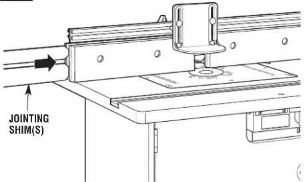
FIG. 25
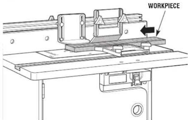
- While firmly holding a piece of scrap wood against the fence and down against the router table, feed a piece of scrap wood toward the bit in the direction shown by the arrow in Fig. 25.
- Using the switch box, turn the router OFF. If any adjustments are needed, unplug the power cord and repeat steps 6–11 until all adjustments are correct. Once you are satisfied with all settings, make the cut with the actual workpiece.
Router Table Operation
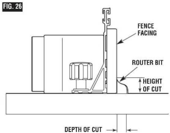
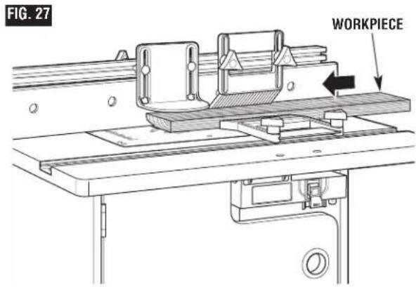
EDGE CUTTING WITH NONPILOTED ROUTER BITS (Figs. 26 and 27)
WARNING
Disconnect the router from the power supply before making
adjustments or changing accessories. Such precautionary safety measures reduce the risk of unintentional tool operation.
NOTE: If the jointing shim is installed, remove it before proceeding.
When using nonpiloted router bits, the fence is used to set the depth of cut. For deep cuts, do not try to cut the total depth all in one pass. Repeat the cut, taking multiple smaller cuts.
- Install the desired bit in the router.
- Follow the instructions on page 27 to set the desired depth of cut and height of cut (Fig. 26). Make sure that the fence and router are SECURELY in place.
-
Position both fence facings so that they clear the bit by 1/4".
-
Tighten the four clamping knobs holding the fence facings in place.
-
Position the featherboards, if desired. See ROUTING USING FEATHERBOARDS on page 26.
-
Remove the board from the table and lower the overhead guard to the operating position. Tighten the guard clamping knobs SECURELY.
NOTE: When making adjustments, use a piece of scrap wood to make trial cuts before making the cut with the actual workpiece.
-
Make sure that both the router and switch box are OFF; then plug the router into the switch box.
-
While firmly holding a piece of scrap wood against the fence and down against the router table, feed a piece of scrap wood toward the bit in the direction shown by the arrow in Fig. 27.
-
Using the switch box, turn the router OFF. If any adjustments are needed, unplug the power cord and repeat steps 2–8 until all adjustments are correct. Once you are satisfied with all settings, make the cut with the actual workpiece.
Guard not shown for clarity
Router Table Operation
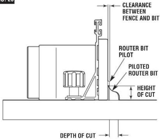
EDGE CUTTING WITH PILOTED ROUTER BITS (Figs. 28 and 29)
WARNING
Disconnect the router from the power supply before making
adjustments or changing accessories. Such precautionary safety measures reduce the risk of unintentional tool operation.
NOTE: If the jointing shim is installed, remove it before proceeding.
- Install the desired piloted bit in the router.
- Follow the instructions on page 27 to set the desired height of cut (Fig. 28). Make sure that the router is SECURELY in place.
- Adjust the router table fence back just enough that the pilot on the router bit will control the depth of cut. The router bit pilot should just barely protrude past the fence facings. Tighten the fence clamping knobs SECURELY.
- Position both fence facings so that they clear the bit by 1/4".
- Tighten the four clamping knobs holding the fence facings in place.
- Remove the board from the table and lower the overhead guard to the operating position. Tighten the guard clamping knobs SECURELY.
NOTE: When making adjustments, use a piece of scrap wood to make trial cuts before making the cut with the actual workpiece.
-
Make sure that both the router and switch box are OFF; then plug the router into the switch box.
-
While firmly holding a piece of scrap wood against the fence and down against the router table, feed a piece of scrap wood toward the bit in the direction shown by the arrow in Fig. 29.
-
Using the switch box, turn the router OFF. If any adjustments are needed, unplug the power cord and repeat steps 2–8 until all adjustments are correct. Once you are satisfied with all settings, make the cut with the actual workpiece.
FIG. 28
Guard not shown for clarity
FIG. 29
WORKPIECE
natural_image
Technical line drawing of a machine tool with a bracket and mounting base (no text or symbols)Router Table Operation
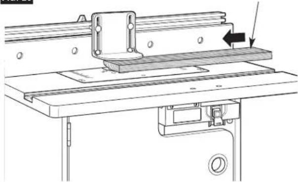
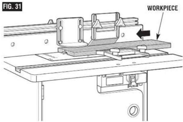
GROOVING, FLUTING, AND VEINING (Figs. 30 and 31)
WARNING
Disconnect the router from the power supply before making
adjustments or changing accessories. Such precautionary safety measures reduce the risk of unintentional tool operation.
NOTE: If the jointing shim is installed, remove it before proceeding.
When performing these routing operations, the use of featherboards and a push shoe is recommended.
For best results and maximum accuracy, the side of the workpiece that will be against the fence must be square and straight.
If you are using a wet/dry vac, it should be connected to the vac port on the back of the table cabinet.
- Install the desired end-cutting bit in the router.
- Follow the instructions on page 27 to set the desired depth of cut (location of cut) and height of cut (Fig. 30). Make sure that the fence and router are SECURELY in place.
IMPORTANT: For deep cuts, do not try to cut the total depth (controlled by the router bit height) all in one pass. Repeat the cut, taking smaller cuts until the desired depth is reached.
- Position both fence facings so that they provide continuous support of the workpiece.
- Tighten the four clamping knobs holding the fence facings in place.
- Position the featherboards, if desired. See ROUTING USING FEATHERBOARDS on page 26.
- Remove the board from the table and lower the overhead guard to the operating position. Tighten the guard clamping knobs SECURELY.
NOTE: When making adjustments, use a piece of scrap wood to make trial cuts before making the cut with the actual workpiece.
- Make sure that both the router and switch box are OFF; then plug the router into the switch box.
- While firmly holding a piece of scrap wood against the fence and down against the router table, feed a piece of scrap wood toward the bit in the direction shown by the arrow in Fig. 31.
- Using the switch box, turn the router OFF. If any adjustments are needed, unplug the power cord and repeat steps 2–8 until all adjustments are correct. Once you are satisfied with all settings, make the cut with the actual workpiece.

Router Table Operation
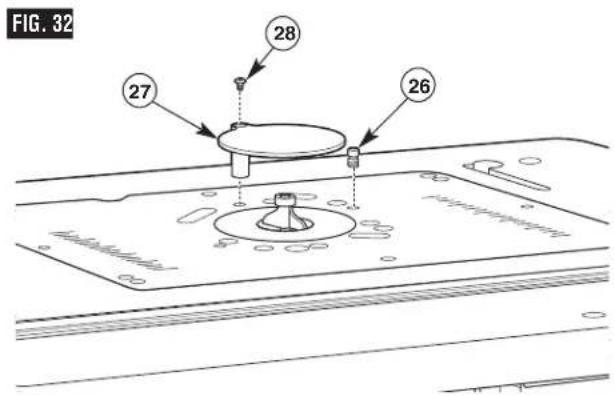
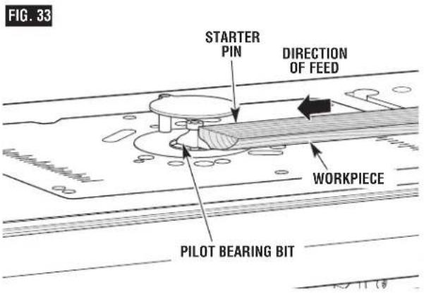
USING THE STARTER PIN FOR EDGE FORMING OF CURVES
The starter pin (26) is used instead of the fence for operations that involve routing curves in the workpiece. It should be used only with bits that have pilot bearings. Thread the starter pin into the threaded hole in the mounting plate and tighten securely with a slotted screwdriver (Fig. 32).
Attach the starter pin guard (27) to the mounting plate by threading a #10-32 x 3/8 "truss-head machine screw (28) through the hole in the guard post and into the threaded hole in the mounting plate. Align the guard with the hole in the mounting plate so it is over the bit, and securely fasten the guard in place.
•Always use the starter pin guard when routing with the starter pin.
- When using the starter pin, the feed direction of the workpiece is always right to left across the front of the bit (Fig. 33).
- Set the workpiece against the front of the starter pin and swing it slowly into the bit.
- While routing, make sure the workpiece is always in contact with the bit's pilot bearing.
WARNING
Use starter pin guard for this type of operation. Do not attempt to rout
very small workpieces. Keep fingers clear of spinning bit.
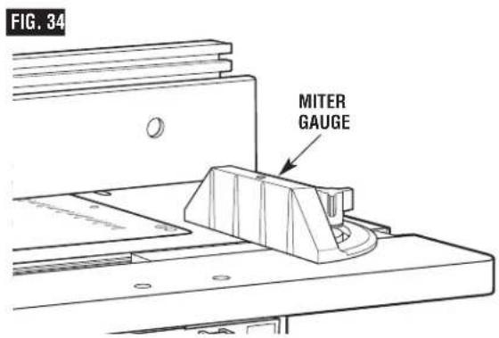
USING A MITER GAUGE (not supplied)
The aluminum T-slot miter gauge slot may be used with most stationary table saw miter gauges that measure 3/4"wide x 3/8"deep.
NOTE: For ALL routing operations requiring the use of the miter gauge with the fence, BE SURE to align the fence using the scales on the top of the router table before making any cuts. Miters can be cut by loosening the knob on the protractor head, turning the protractor head up to 60° in either direction, and retightening the protractor head knob.
Notes
Table des Matières
CONSIGNES DE SÉCURITÉ
natural_image
Technical line drawing of two different types of screw fasteners (no text or symbols)(38) Vis Allen connector-tête
natural_image
Technical line drawing of two threaded fasteners (no text or symbols)(39) Boulon de carrosserie 1/4-20 x 1 po

natural_image
Technical line drawing of two types of screws (screw and nut) with threaded ends, no text or symbols present.(40) Boulon de carrosserie 1/4-20 x ½ po
natural_image
Technical line drawing of two types of screws (two and one) with threaded ends, no text or symbols present.(41) Boulon de carrosserie 1/4-20 x 3% po
natural_image
Technical line drawing of a two-pin screw with threaded shaft (no text or symbols)natural_image
Technical line drawing of two screw components: a circular head with cross-shaped end and a straight threaded base (no text or symbols)natural_image
Simple line drawing of a two-layered paperclip or clip (no text or symbols)FIG. 9
natural_image
Technical line drawing of a mechanical assembly with flanges and components (no text or symbols)FIG. 12
natural_image
Line drawing of a printer inserted into a rack, no text or symbols presentMARCHE (HAUT)
natural_image
Line drawing of a mechanical device with a belt and housing (no text or symbols)ARRÊT (BAS)
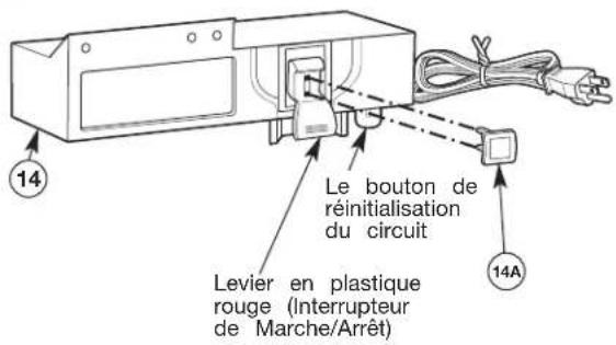
FIG. 19
natural_image
Technical line drawing of a machine tool with no visible text or symbolsFIG. 20
natural_image
Technical line drawing of a machine tool with mounting bracket and workpiece (no text or symbols)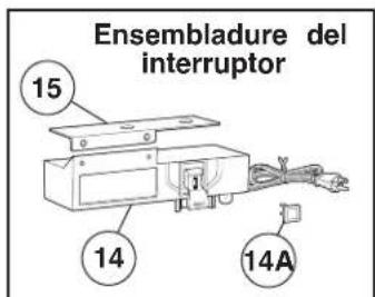
natural_image
Technical line drawing of two different types of screw fasteners (no text or symbols)natural_image
Technical line drawing of two types of screws (no text or symbols present)(39) Perno de carruaje 1/4-20 x 1"
natural_image
Technical line drawing of two types of screws (screw and nut) with threaded ends, no text or symbols present.(40) Perno de carruaje 1/4-20 x 112
natural_image
Technical line drawing of two types of screws (screw and nut) with threaded ends, shown from different angles (no text or symbols)(41) Perno de carruaje 1/4-20 3/4"1
natural_image
Technical line drawing of a screw with two different threaded positions (no text or symbols)(46) Tornillo de máquina Phillips 1/4-20 x 1½"
(47) Tornillo de máquina Phillips #10-24 x 1/2"
(48) Tornillo de máquina Phillips #8-32 x 1/2"
(49) Tuerca KEPS 1/4-20
(50) Tornillo de máquina Phillips 5/16-18x 1/2"
(51) Tornillo de máquina Phillips M4 x 20
natural_image
Simple line drawing of two parallel rectangular shapes with no text or symbols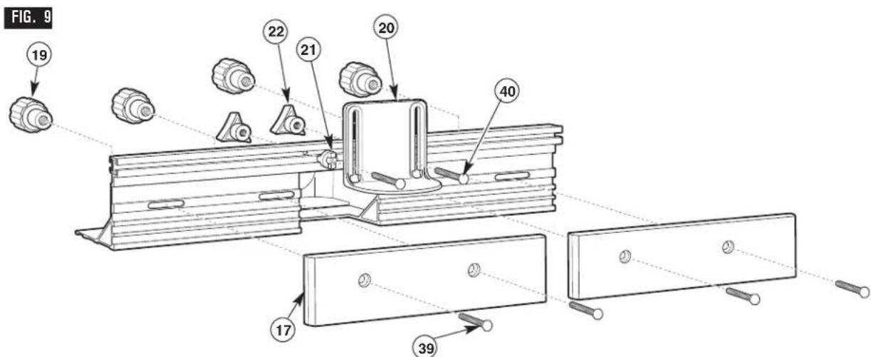
natural_image
Line drawing of a printer emitting a paper airplane into a container (no text or symbols)ENCENDIDO (ARRIBA)
natural_image
Line drawing of a mechanical device with a cylindrical component inserted into a housing (no text or symbols)APAGADO (ABAJO)
FIG. 17
CÓMO ARMAR LA LAS TABLAS DE BISELADO (Figs. 18–20)
natural_image
Technical line drawing of a machine tool with baseplate and workpiece (no text or symbols)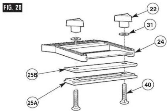
natural_image
Technical line drawing of a mechanical assembly with mounting base and clamping mechanism (no text or symbols)© Robert Bosch Tool Corporation, 1800 W. Central Road, Mt. Prospect, IL 60056-2230
Exportado por: Robert Bosch Tool Corporation, Mt. Prospect, IL 60056-2230, E.U.A.