GKF125CE Professional - Milling machine BOSCH - Free user manual and instructions
Find the device manual for free GKF125CE Professional BOSCH in PDF.

| Product Type | Hand Router (Router) |
| Brand | Bosch |
| Model | GKF125CE Professional |
| No-load Speed | 16,000 – 35,000 RPM (electronic variable speed, 6 positions) |
| Collet Capacity | 1/4 inch (6.35 mm) shank |
| Power Supply | 120 V, 60 Hz, 6.5 A |
| Power | 750 W (estimated) |
| Construction | Double Insulation (Class II) |
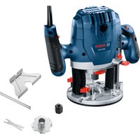
| Included Bases | Fixed Base PR101 (aluminum) |
| Optional Bases | Plunge Base PR111, Round Sub-base PR110, Edge Guide PR102 |
| Features | Soft Start, Electronic Speed Control (Constant Response™), Micrometer Depth Adjustment, Finger Support Pocket |
| Safety | Shaft Lock, Finger Guard, Motor Unlock Button, Overload Protection |
| Included Accessories | Collet Wrench, Sub-base, Edge Guide (depending on version) |
| Maintenance | Cleaning with dry compressed air, gear lubrication when changing brushes, periodic brush inspection |
| Warranty | 1 year (parts and labor) |
| Approximate Weight | 1.5 kg (depending on base) |
Frequently Asked Questions - GKF125CE Professional BOSCH
User questions about GKF125CE Professional BOSCH
0 question about this device. Answer the ones you know or ask your own.
Ask a new question about this device
Download the instructions for your Milling machine in PDF format for free! Find your manual GKF125CE Professional - BOSCH and take your electronic device back in hand. On this page are published all the documents necessary for the use of your device. GKF125CE Professional by BOSCH.
USER MANUAL GKF125CE Professional BOSCH
IMPORTANT Read Before Using
IMPORTANT Lire avant usage
IMPORTANTE Leer antes de usar

natural_image
Icon of a person reading a book inside a circle (no text or symbols)Operating/Safety Instructions Consignes d'utilisation/de sécurité Instrucciones de funcionamiento y seguridad
GKF125CE
natural_image
Line drawing of a Bosch vacuum cleaner with control panel and fan (no text or symbols)
BOSCH
Call Toll Free for Consumer Information and Service Locations Pour obtenir des informations et les adresses de nos centres de service après-vente, appelez ce numéro gratuit Llame gratis para obtener información para el consumidor y ubicaciones de servicio
1-877-BOSCH99 (1-877-267-2499) www.boschtools.com
For English Version See page 2
| Safety SymbolsThe definitions below describe the level of severity for each signal word. Please read the manual and pay attention to these symbols. | |
 | This is the safety alert symbol. It is used to alert you to potential personal injury hazards. Obey all safety messages that follow this symbol to avoid possible injury or death. |
 | DANGER indicates a hazardous situation which, if not avoided, will result in death or serious injury. |
 | WARNING indicates a hazardous situation which, if not avoided, could result in death or serious injury. |
 | CAUTION indicates a hazardous situation which, if not avoided, could result in minor or moderate injury. |
General Power Tool Safety Warnings
WARNING
Read and understand all instructions before using this appliance.
Failure to follow all instructions listed below, may result in electric
shock, fire and/or serious personal injury.
SAVE THESE INSTRUCTIONS
▶ Work area safety
Keep work area clean and well lit.
Cluttered or dark areas invite accidents.
Do not operate power tools in explosive atmospheres, such as in the presence of flammable liquids, gases or dust. Power tools create sparks which may ignite the dust or fumes.
Keep children and bystanders away while operating a power tool. Distractions can cause you to lose control.
▶ Electrical safety
Power tool plugs must match the outlet. Never modify the plug in any way. Do not use any adapter plugs with earthed (grounded) power tools. Unmodified plugs and matching outlets will reduce risk of electric shock.
Avoid body contact with earthed or grounded surfaces such as pipes, radiators, ranges and refrigerators. There is an increased risk of electric shock if your body is earthed or grounded.
Do not expose power tools to rain or wet conditions. Water entering a power tool will increase the risk of electric shock.
Do not abuse the cord. Never use the cord
for carrying, pulling or unplugging the power tool. Keep cord away from heat, oil, sharp edges or moving parts. Damaged or entangled cords increase the risk of electric shock.
When operating a power tool outdoors, use an extension cord suitable for outdoor use. Use of a cord suitable for outdoor use reduces the risk of electric shock.
If operating a power tool in a damp location is unavoidable, use a Ground Fault Circuit Interrupter (GFCI) protected supply. Use of an GFCI reduces the risk of electric shock.
▶ Personal safety
Stay alert, watch what you are doing and use common sense when operating a power tool. Do not use a power tool while you are tired or under the influence of drugs, alcohol or medication. A moment of inattention while operating power tools may result in serious personal injury.
Use personal protective equipment.
Always wear eye protection. Protective equipment such as dust mask, non-skid safety shoes, hard hat, or hearing protection used for appropriate conditions will reduce personal injuries.
Prevent unintentional starting. Ensure the switch is in the off-position before connecting to power source and / or battery pack, picking up or carrying the tool. Carrying power tools with your finger on the switch or energizing power tools that have the switch on invites accidents.
Remove any adjusting key or wrench before turning the power tool on. A wrench or a key left attached to a rotating part of the power tool may result in personal injury.
Do not overreach. Keep proper footing and balance at all times. This enables better control of the power tool in unexpected situations.
Dress properly. Do not wear loose clothing or jewelry. Keep your hair, clothing and gloves away from moving parts. Loose clothes, jewelry or long hair can be caught in moving parts.
If devices are provided for the connection of dust extraction and collection facilities, ensure these are connected and properly used. Use of dust collection can reduce dust-related hazards.
▶ Power tool use and care
Do not force the power tool. Use the correct power tool for your application. The correct power tool will do the job better and safer at the rate for which it was designed.
Do not use the power tool if the switch does not turn it on and off. Any power tool that cannot be controlled with the switch is dangerous and must be repaired.
Disconnect the plug from the power
source and/or the battery pack from the power tool before making any adjustments, changing accessories, or storing power tools. Such preventive safety measures reduce the risk of starting the power tool accidentally.
Store idle power tools out of the reach of children and do not allow persons unfamiliar with the power tool or these instructions to operate the power tool. Power tools are dangerous in the hands of untrained users.
Maintain power tools. Check for misalignment or binding of moving parts, breakage of parts and any other condition that may affect the power tool's operation. If damaged, have the power tool repaired before use. Many accidents are caused by poorly maintained power tools.
Keep cutting tools sharp and clean. Properly maintained cutting tools with sharp cutting edges are less likely to bind and are easier to control.
Use the power tool, accessories and tool bits etc. in accordance with these instructions, taking into account the working conditions and the work to be performed. Use of the power tool for operations different from those intended could result in a hazardous situation.
▶ Service
Have your power tool serviced by a qualified repair person using only identical replacement parts. This will ensure that the safety of the power tool is maintained.
Safety Rules for Routers
Hold power tool by insulated gripping surfaces, because the cutter may contact its own cord. Cutting a "live" wire may make exposed metal parts of the power tool "live" and shock the operator.
Use clamps or another practical way to secure and support the workpiece to a stable platform. Holding the work by your hand or against the body leaves it unstable and may lead to loss of control.
If cutting into existing walls or other blind areas where electrical wiring may exist is unavoidable, disconnect all fuses or circuit breakers feeding this worksite.
Always make sure the work surface is free from nails and other foreign objects.
Cutting into a nail can cause the bit and the tool to jump and damage the bit.
Never hold the workpiece in one hand and the tool in the other hand when in use.
Never place hands near or below cutting surface. Clamping the material and guiding the tool with both hands is safer.
Never lay workpiece on top of hard surfaces, like concrete, stone, etc...
Protruding cutting bit may cause tool to jump.
Always wear safety goggles and dust
mask. Use only in well ventilated area. Using personal safety devices and working in safe environment reduces risk of injury.
After changing the bits or making any adjustments, make sure the collet nut and any other adjustment devices are securely tightened. Loose adjustment device can unexpectedly shift, causing loss of control, loose rotating components will be violently thrown.
Never start the tool when the bit is engaged in the material. The bit cutting edge may grab the material causing loss of control of the cutter.
The direction of feeding the bit into the material is very important and it relates to the direction of bit rotation. When viewing the tool from the top, the bit rotates clockwise. Feed direction of cutting must be counter-clockwise. NOTE: inside and outside cuts will require different feed direction, refer to section on feeding the router. Feeding the tool in the wrong direction, causes the cutting edge of the bit to climb out of the work and pull the tool in the direction of this feed.
Never use dull or damaged bits. Sharp bits must be handled with care. Damaged bits can snap during use. Dull bits require more force to push the tool, possibly causing the bit to break.
Never touch the bit during or immediately after the use. After use the bit is too hot to be touched by bare hands.
Never lay the tool down until the motor has come to a complete standstill. The spinning bit can grab the surface and pull the tool out of your control.
Cutter diameter must be at least 1/4" smaller than opening for the bit and cutter.
Additional Safety Warnings
Use only router bits that have shank diameters that match the installed collet.
Using a router bit that has a smaller shank could cause the bit to come loose during operation and become a projectile.
Never operate router bits at speeds that are higher than their maximum rated speed. Router bits running faster than their rated speed can break and fly apart.
GFCI and personal protection devices like electrician's rubber gloves and footwear will further enhance your personal safety.
Do not use AC only rated tools with a DC power supply. While the tool may appear to work, the electrical components of the AC rated tool are likely to fail and create a hazard to the operator.
Keep handles dry, clean and free from oil and grease. Slippery hands cannot safely control the power tool.
Use clamps or other practical way to secure and support the workpiece to a stable platform. Holding the work by hand or against your body leaves it unstable and may lead to loss of control.
Develop a periodic maintenance schedule for your tool. When cleaning a tool be careful not to disassemble any portion of the tool since internal wires may be misplaced or pinched or safety guard return springs may be improperly mounted. Certain
cleaning agents such as gasoline, carbon tetrachloride, ammonia, etc. may damage plastic parts.
Risk of injury to user. The power cord must only be serviced by a Bosch Factory Service Center or Autho rized Bosch Service Station.
WARNING
Some dust created by power sanding, sawing,
grinding, drilling, and other construction activities contains chemicals known to cause cancer, birth defects or other reproductive harm. Some examples of these chemicals are:
- Lead from lead-based paints,
- Crystalline silica from bricks and cement and other masonry products, and
- Arsenic and chromium from chemically-treated lumber.
Your risk from these exposures varies, depending on how often you do this type of work. To reduce your exposure to these chemicals: work in a well ventilated area, and work with approved safety equipment, such as those dust masks that are specially designed to filter out microscopic particles.
Symbols
IMPORTANT: Some of the following symbols may be used on your tool. Please study them and learn their meaning. Proper interpretation of these symbols will allow you to operate the tool better and safer.
| Symbol Designation/Explanation | |
| V Volts (voltage) | |
| A Amperes (current) | |
| Hz Hertz (frequency, cycles per second) | |
| W Watt (power) | |
| kg Kilograms (weight) | |
| min Minutes (time) | |
| s Seconds (time) | |
| ∅ | Diameter (size of drill bits, grinding wheels, etc.) |
| n_0 | No load speed (rotational speed at no load) |
| n Rated | speed (maximum attainable speed) |
| .../min | Revolutions or reciprocation per minute (revolutions, strokes, surface speed, orbits etc. per minute) |
| 0 Off position (zero speed, zero torque...) | |
| 1, 2, 3, ...I, II, III, | Selector settings (speed, torque or position settings. Higher number means greater speed) |
| 0 | Infinitely variable selector with off (speed is increasing from 0 setting) |
| → | Arrow (action in the direction of arrow) |
| ~ | Alternating current (type or a characteristic of current) |
| --- | Direct current (type or a characteristic of current) |
| ~ | Alternating or direct current (type or a characteristic of current) |
| ☐ | Class II construction (designates double insulated construction tools) |
| ⊕ | Earthing terminal (grounding terminal) |
Symbols (continued)
IMPORTANT: Some of the following symbols may be used on your tool. Please study them and learn their meaning. Proper interpretation of these symbols will allow you to operate the tool better and safer.
| Symbol Designation / Explanation | |
 | Designates Li-ion battery recycling program |
 | Designates Ni-Cad battery recycling program |
 | Alerts user to read manual |
 | Alerts user to wear eye protection |
 | This symbol designates that this tool is listed by Underwriters Laboratories. |
 | This symbol designates that this component is recognized by Underwriters Laboratories. |
 | This symbol designates that this tool is listed by Underwriters Laboratories, to United States and Canadian Standards. |
 | This symbol designates that this tool is listed by the Canadian Standards Association. |
 | This symbol designates that this tool is listed by the Canadian Standards Association, to United States and Canadian Standards. |
 | This symbol designates that this tool is listed by the Intertek Testing Services, to United States and Canadian Standards. |
 | This symbol designates that this tool complies to NOM Mexican Standards. |
Functional Description and Specifications
WARNING
Disconnect the plug from the power source before making any assembly, adjustments or changing accessories. Such preventive
safety measures reduce the risk of starting the tool accidentally.
Fixed-Base Palm Router
Model Number
GKF125CE
Bit Capacity
1/4" shank
Max. Cutter Diameter
*
* Cutter diameter must be at least 1/4" smaller than opening for the bit and cutter.
NOTE: For tool specifications refer to the nameplate on your tool.
Functional Description and Specifications
WARNING
Disconnect the plug from the power source before making any assembly, adjustments or changing accessories. Such preventive
safety measures reduce the risk of starting the tool accidentally.
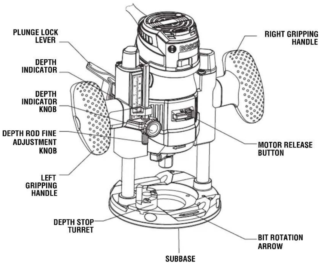
Plunge-Base Palm Router Configuration
FIG. 2
Assembly
▶ Selecting Bits
Your Bosch palm router is designed for a wide variety of routing applications that use 1/4" shank bits. These include woodworking applications such as edge forming, grooving, and sign making. This router is also ideal for trimming laminates, phenolics, and other materials that have been bonded to a substrate overhang the substrate typically by about 1/8" (3 mm).
A wide assortment of router bits with different profiles are available as accessories. Only use good quality bits.
WARNING
Use only router bits that have shank diameters that match the installed collet. Using a router bit that has a smaller shank could cause the bit to come loose during operation and become a projectile.
WARNING
Never operate router bits at speeds that are higher than their maximum rated speed. Router bits running faster than their rated speed can break and fly apart.
WARNING
To prevent personal injury, always remove the plug from power source before removing or in stal ling bits or accessories.
▶ Installing a Router Bit
- Lay the router or motor on its side. The router can also be stood "on its head" for bit changes.
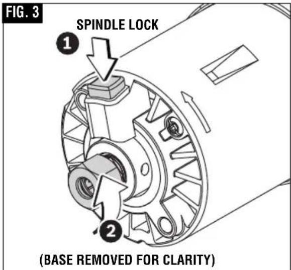
- Press spindle lock to prevent rotation of collet chuck. NOTE: it may be necessary to rotate collet nut to engage spindle lock (Fig. 3).
- Next, use the collet wrench to loosen the collet chuck assembly in a counter-clockwise direction (viewed from bottom of router).
- Insert the shank of the router bit into the collet chuck assembly as far as it will go, then back the shank out until the cutters are
approximately 1/8" to 1/4" away from the collet nut face.
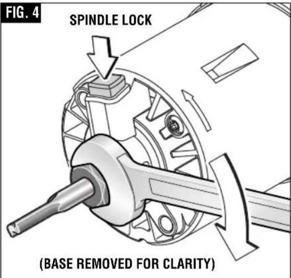
- With the router bit inserted and the spindle lock engaged, use the collet wrench to firmly tighten the collet chuck assembly in a clockwise direction (viewed from bottom of router) (Fig. 4).
To ensure proper gripping of the router bit and minimize run-out, the shank of the router bit must be inserted at least 5/8".
WARNING Cutter diameter must be at least 1/4" smaller than opening for the bit and cutter.
⚠️ CAUTION To prevent damage to tool, do not tighten collet without a bit.
Assembly
NOTE: The bit shank and chuck should be clean and free of dust, wood, residue, and grease before assembling.
▶ Removing the Router Bit
- Press spindle lock to prevent rotation of collet chuck and turn the collet chuck assembly in a counter-clockwise direction.
- Once the collet chuck assembly is loosened, continue to turn the collet chuck assembly until it pulls the collet free from the spindle, and the router bit can be removed.
NOTE: The collet chuck is self-extracting; it is NOT necessary to strike the collet chuck to free the router bit.
▶ Collet Chuck Care
With the router bit removed, continue to turn the collet chuck counterclockwise until it is free of the shaft. To assure a firm grip, occasionally blow out the collet chuck with compressed air, and clean the taper in the armature assembly shaft with a tissue or fine brush. The collet chuck is made up of two component parts that snap together (Fig. 5); check to see that the collet is properly seated in the collet chuck nut and lightly thread the collet chuck back onto the armature shaft. Replace worn or damaged collet chucks immediately.
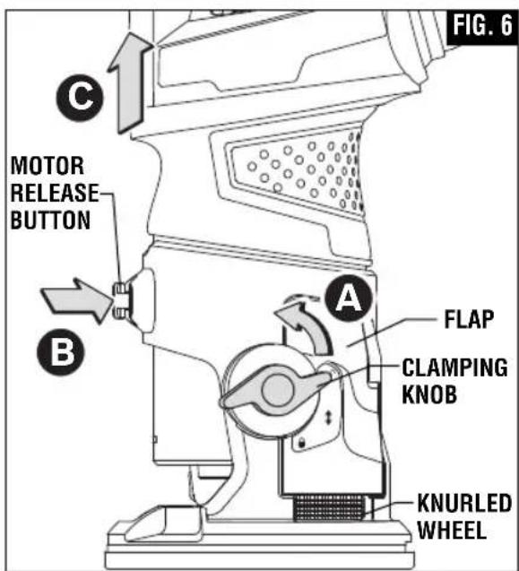
▶ Removing Motor from PR101 Fixed Base
- Turn the clamping knob to the unlocked position (A, Fig. 6).
- Pull the motor away from base until it stops. (Do not press on the flap in the base while pulling the motor.) (C, Fig. 6).
- Press and hold the motor release button. (B, Fig. 6).
- Pull motor out of base (C, Fig. 6).

Assembly
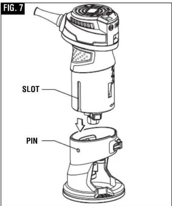
▶ Installing the Motor into PR101 Fixed Base
- Open the clamping knob to the unlocked position (A, Fig. 6).
- Align the slot on the motor with the pin on the base (Fig. 7)
WARNING
To avoid pinching injury, keep all parts
of your hands away from the top rim of the base and away from metal section of the motor when pushing motor into base.
- Push the motor into the base to the approximate desired position has been reached. Do not press on the flap in the base while installing the motor.
- Turn the clamping knob to the bottom, locked position (E, Fig. 9). Always make sure the motor sits tightly in the base.
▶ Check Subbase Location
WARNING
Cutter diameter must be at least
1/4" smaller than opening for the bit and cutter.
Make sure that the bit and its cutter are centered in the subbase opening. If necessary, adjust the location of the subbase as follows:
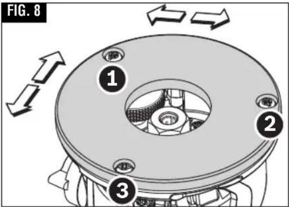
- Loosen the three screws that hold the subbase.
- Adjust the location of the subbase as needed so that the bit and its cutter are centered in the subbase opening. The optional RA1151 centering device makes this easy.
- Tighten the three screws that hold the subbase (Fig. 8).
When the subbase has been centered in this manner, any part of the subbase can be used as a guiding surface without worrying about a difference in the cut line. See "Guiding The Router" on page 13.
Note: This subbase is not designed for use with template guides. The optional PR110 Attachment allows use of template guides with this palm router.
Operating Instructions
WARNING
Disconnect the plug from the power
source before making any assembly, adjustments or changing
accessories. Such preventive safety measures reduce the risk of starting the tool accidentally.
Bosch routers are designed for speed, accuracy and convenience in performing cabinet work, fluting, beading, cove-cutting, rounding edges, dovetailing, etc. They will enable you to accomplish inlay work, decorative edges and many types of special routing.
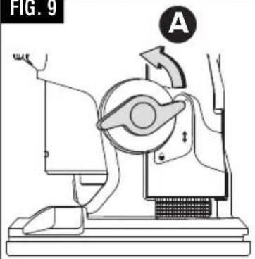
▶ Setting the Depth of Cut
Adjust the depth-of-cut only when the motor is switched off.
- Install desired router bit.
- Place the router on the workpiece.
- Turn the clamping knob to the top, unlocked position (A, Fig. 9).
- Slowly lower the motor until the router bit touches the workpiece (Fig. 9)
- Note the reading on the scale (above the motor release button) and add the desired depth-of-cut to this value to determine the target scale value.
Operating Instructions
FIG. 9
natural_image
Diagram of a mechanical device with labeled component A, showing no readable text or symbols beyond label and arrow.
natural_image
Mechanical device diagram showing a rotating arm and base with a circular symbol (no text or labels)
natural_image
Diagram of a mechanical device with labeled component E, showing no readable text or symbols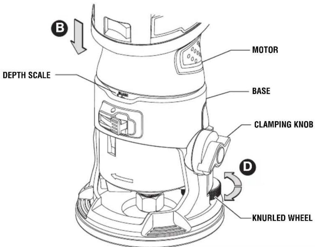
- Lower the motor until the target scale value is reached.
- Turn the clamping knob to the middle position symbol, for fine adjustment (C, Fig. 9). Always make sure the motor is held tightly in the base.
- Check the depth-of-cut and make fine adjustment if necessary (D, Fig. 9). See FINE DEPTH ADJUSTMENT section below for details.
- Turn the clamping knob to the bottom, locked position (E, Fig. 9). Always make sure the motor sits tightly in the base.
Note: the depth of the motor and bit
may shift very slightly when the clamping knob is turned to the locked position.
- Make a trial cut to verify that the router is set to make the cut as desired.
▼ FINE DEPTH ADJUSTMENT
Adjust the depth-of-cut only when the motor is switched off.
- Turn the clamping to the middle position symbol, for fine adjustment (C, Fig. 9).
- Adjust the desired depth-of-cut with the knurled wheel on back of base (D, Fig. 9). Rotate the knurled wheel clockwise to increase the
Operating Instructions
routing depth, counterclockwise to decrease the cutting depth. Each complete rotation of the dial equals 1.25 mm (approximately 3/64").
- Turn the clamping knob to the bottom, locked position (E, Fig. 9). Always make sure the motor sits tightly in the base.
- Check the depth-of-cut and make an additional fine adjustment if necessary.
Note: the depth of the motor and bit may shift very slightly when the clamping knob is turned to the locked position.
- Make a trial cut to verify that the router is set to make the cut as desired.
▼ DEEP CUTS
For deep cuts, make several progressively deeper cuts by starting at one depth and then make several subsequent passes, increasing the cutting depth with each pass.
To be certain that your depth settings are as desired, you may want to make test cuts in scrap material before beginning work.
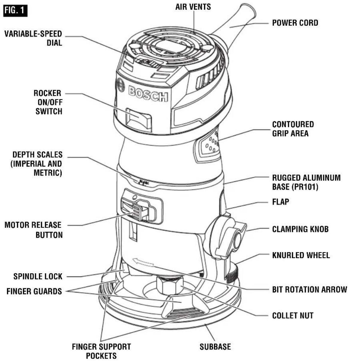
▶ Rocker "On/Off" Switch
Your tool can be turned “ON” or “OFF” by the rocker switch located on the motor housing. One side of the switch is marked “I” for “ON”, and the other side of switch is marked “O” for “OFF”.
TO TURN THE TOOL "ON": Push the side of the switch marked "I".
TO TURN THE TOOL "OFF": Push the side of the switch marked "O".
▼ SOFT START FEATURE
Electronic feedback control minimizes torque twist customary in routers by limiting the speed at which motor starts.
▼ ELECTRONIC VARIABLE SPEED CONTROL
The electronic speed control feature allows motor speed to be matched to cutter size and material hardness for improved finish, extended bit life, and
higher performance. Speed changes are achieved by rotating the Control Dial RIGHT to increase speed or LEFT to decrease as indicated on housing (Fig. 1). Speed may be changed while tool is on. The reference numbers on the dial facilitate re-setting control to desired speed.
The speed chart indicates the relationship between settings and application, exact settings are determined by operator experience and preference. The bit manufacturer may also have a speed recommendation.
WARNING
Never operate router bits at speeds that are higher than their maximum rated speed. Router bits running faster than their rated speed can break and fly apart.
| DIAL SETTING | RPM | APPLICATION |
| 1 | 16000 | Larger-diameter bits and cutters. |
| 2 | 18000 | |
| 3 | 20000 | |
| 4 | 22500 | Softwoods, plastics, laminates, smaller diameter bits and cutters |
| 5 | 27500 | |
| 6 | 35000 |
▼ CONSTANT RESPONSE™ CIRCUITRY
The router's Constant Response™ Circuitry monitors and adjusts power to maintain the desired RPM for consistent performance and control.
Operating Instructions
▶ Feeding the Router
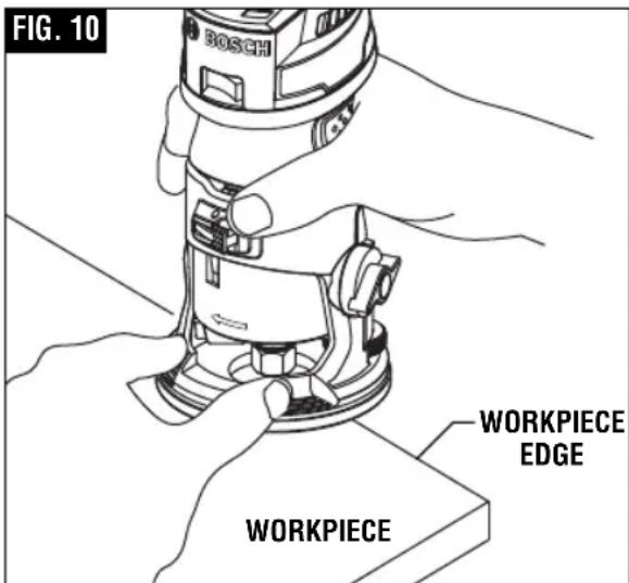
In addition to the main palm-grip area at the back of the motor housing and base, the base has Bosch-exclusive finger support pockets to provide additional stability for the router. The pockets feature finger guards to provide a barrier between the finger pockets and the bit area (Fig 10).
WARNING
When using finger pockets, always place both finger pockets over the workpiece and always hold the router in a way that allows you to see your finger and thumb.
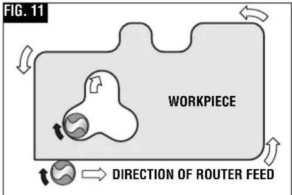
As seen from the top of the router, the bit turns clockwise and the bit's cutting edges are positioned to best cut into the workpiece. Therefore, the most efficient cut is made by feeding the router so that the bit turns into the workpiece, not away. Figure 11 shows proper feed for various cuts. How fast you feed depends on the hardness of the material and the size of the cut. For some materials, it is best to make several cuts of increasing depth.
If the router is hard to control, heats up, runs very slowly or leaves an imperfect cut, consider these causes:
- Wrong direction of feed – hard to control.
- Feeding too fast — overloads motor.
- Dull bit - overloads motor.
- Cut is too large for one pass — overloads motor.
- Feeding too slow – leaves friction burns on work.
Feed smoothly and steadily (do not force). You will soon learn how the router sounds and feels when it is working best.
Always hold the router off the work when turning the switch on or off. Contact the work with the router after the router has reached full speed, and remove it from the work before turning the switch off. Operating in this manner will prolong switch and motor life and will greatly increase the quality of your work.
natural_image
Technical illustration of a mechanical clamp assembly on a wooden base, showing a clamping mechanism (no text or symbols present)▼ RATE OF FEED
When routing or doing related work in wood and plastics, the best finishes will result if the depth of cut and feed rate are regulated to keep the motor operating at high speed. Feed the router at a moderate rate. Soft materials require a faster feed rate than hard materials.
The router may s tall if improperly used or overloaded. Reduce the feed rate to prevent possible damage to the tool. Always be sure the collet chuck is tightened securely before use. Always use router bits with the shortest cutting length necessary to produce the desired cut. This will minimize router bit run-out and chatter.
It may be necessary to make the cut in more than one pass with progressively deeper settings to avoid overloading the motor. If the bit cuts freely and the motor does not slow down, the cutting depth is generally correct.
Operating Instructions
▼ GUIDING THE ROUTER
The router can be guided through the work in any of several ways. The method you use depends, of course, on the demands of the particular job and on convenience.
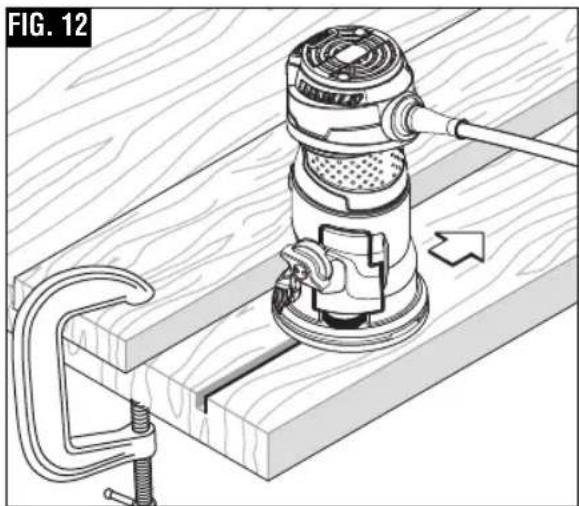
For routing operations such as grooving or dadoing, it is often necessary to guide the tool in a line parallel to a straight edge. One method of obtaining a straight cut is to securely clamp a board or other straightedge to the work surface, and guide the edge of the router sub-base along this path (Fig. 12).
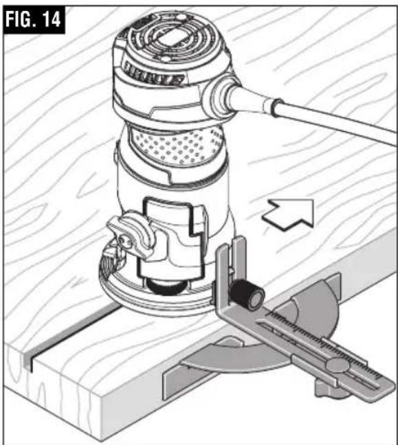
▶ PR102 Edge Guide
The edge guide is an optional accessory that will guide the router parallel to a straight edge (Fig. 14).
The edge guide is supplied in two parts held together with a bolt, wing nut and washer.
natural_image
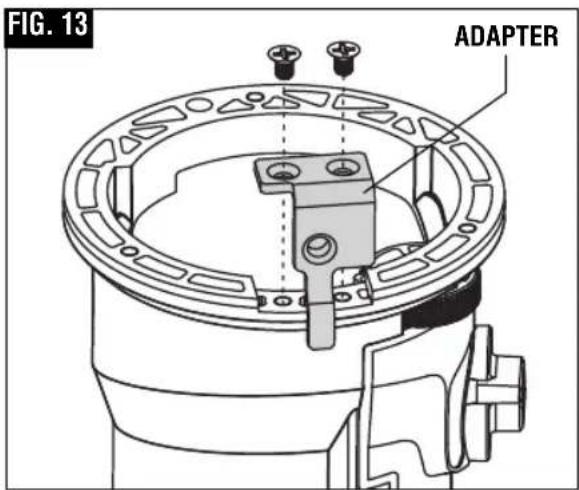
Technical illustration of a mechanical device with a tool and clamping mechanism, no visible text or symbols▼ATTACHING THE EDGE GUIDE
- Remove the subbase by unscrewing the three screws.
- Position the adapter in the gap in the base.
- Fasten the adapter using the two Philips screws (Fig. 13).
- Reattach the subbase.
Note: See "Check Subbabse Location" section on how to center the subbase.
- Attach the edge guide to the adapter using the knurled screw with two washers (Fig. 14).
The guide features a scale for accurately positioning the edge guide relative to the bit. With the guide installed and adjusted, the router should be fed normally, keeping the guide in contact with the edge of the workpiece at all times.
The edge guide can also be positioned directly under the router base for operations where a cut is needed close to or at the edge of the work, such as when rounding off deck planks.
natural_image
Technical line drawing of a mechanical assembly (no text or symbols)Operating Instructions
▼ USING SELF-PILOTED BITS
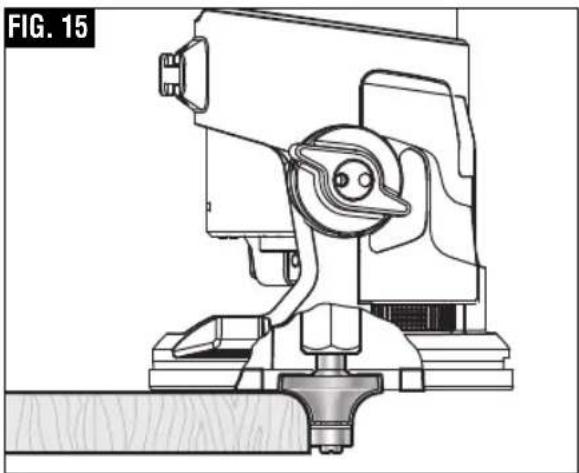
Self-piloted bits have an integral round tip or ball bearing which rides against the work surface above or below the cutter to control horizontal cutting depth (Fig. 15). When using these bits, neither the roller guide or the straight guide is required. When guiding against a laminated surface, use wax or other lubricant and do not apply excess pressure or the piloted end may mar the work. Bearing pilots must be kept clean and free of adhesive or other residue. Router bit bearings are sealed and permanently lubricated, and should be replaced when they no longer turn freely to avoid damaging the work surface.
▶ PR110 Round Subbase and Use of Template Guide Bushings with PR101 Fixed base
(Available as optional accessories)
Optional large round subbases are available separately and allow various template guide bushings to be used with the palm routers.
Template guide bushings are used to guide the router to repeatedly make consistent openings and inlays using various templates (also referred to as patterns and jigs). Templates for standard routing applications are available commercially and templates for specialty applications are typically made by users for their specific needs.
The PR110 Round Subbase accepts threaded template guide adapters.
▼ PR110 ATTACHMENT ROUND SUBBASE OF THREADED TEMPLATE GUIDE (Fig. 16)
- Remove regular subbase.
- Loosely attach round subbase using panhead screws that come with that accessory.
- Attach the threaded template guide by putting the template guide through the bottom and attaching the ring from the top.
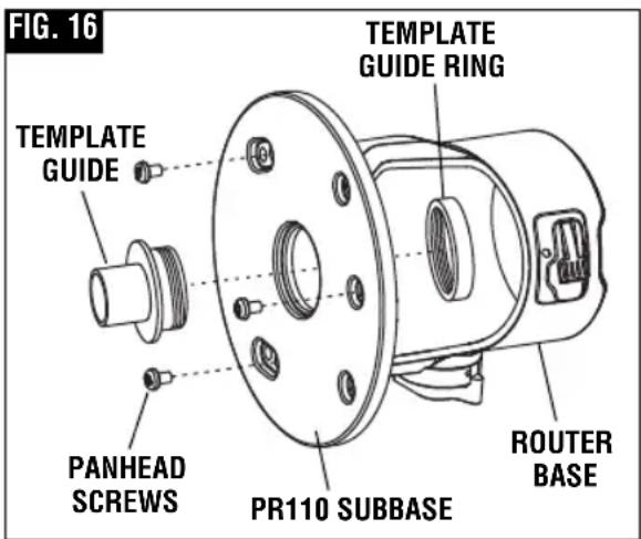
- Center the template guide around the bit. (The optional Bosch RA1151 Centering device can be used to ensure that the template guide is properly centered.)
- Tighten the panhead screws to hold the template guide and subbase in position.
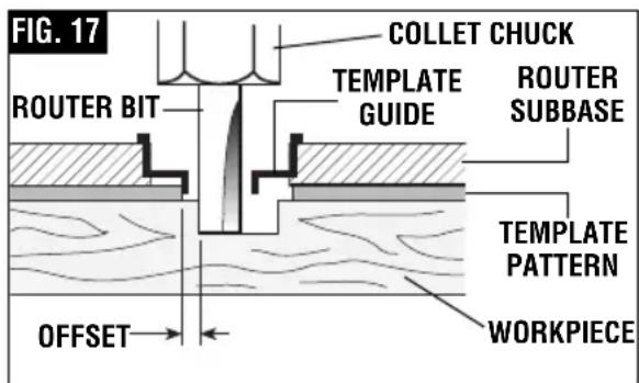
▼ CREATING TEMPLATES
Template patterns can be made of plywood, hardboard, metal or even plastic. The design can be cut with a router, jigsaw, or other suitable cutting tool. Remember that the pattern will have to be made to compensate for the distance between the router bit and the template guide (the “offset”), as the final workpiece will differ in size from the template pattern by that amount, due to the bit position (Fig. 17).
Operating Instructions
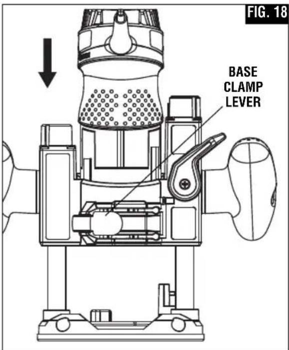
▶ PR111 Plunge Base
(Included with GKF125CEPK and sold separately)
To install motor in plunge base:
- Release the base clamp lever (Fig. 18).
- Push the motor into the base as far as it will go.
- Fasten the base clamp lever. If additional clamping force is desired: using a 8 mm wrench, rotate clamp nut clockwise SLIGHTLY (1/8 turn or less), then test clamp. Do not over-tighten.
To remove motor from plunge base:
- Release the base clamp lever.
- Press and hold the motor release button.
- Pull motor up and out of base.
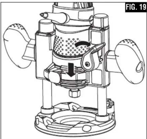
▼ DEPTH ADJUSTMENT
The plunge feature simplifies depth adjustments and will allow the cutting bit to easily and accurately enter the workpiece.
-
To lower, push plunge lock lever to the left, apply downward pressure until you reach desired depth, and release pressure on lever to lock (Fig. 19). The plunge lock lever is spring loaded and returns automatically to the locked position.
-
To raise the router, push plunge lock lever to the left, release pressure on router and the router will automatically retract the bit from the workpiece. It is advisable to retract the bit whenever it is not engaged in work piece.
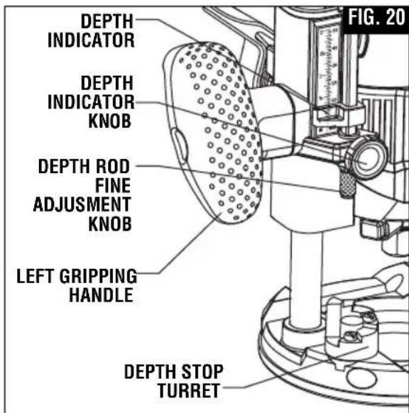
▼ DEPTH ROD AND TURRET
The depth rod and the depth stop turret are used to control cutting depth as follows;
- With the bit installed, gently lower the motor until the tip of the router bit just contacts the level surface the router is sitting on. This is the "zero" position, from which further depth adjustments can be accurately made.
-
Rotate depth stop turret until the lowest step is aligned with the depth rod. Loosen depth indicator knob and lower the depth rod until it contacts the lowest step of the turret. Slide the depth indicator until the red line indicates zero on the depth scale, indicating the point at which the bit just contacts the work (Fig. 20).
-
Slide the depth rod up until the red depth indicator line attains the desired cutting depth, and secure the rod in position by firmly tightening the depth indicator knob.
natural_image
Technical line drawing of a mechanical device with internal components and a downward arrow indicating motion (no text or symbols)Operating Instructions
- The desired depth of cut may now be achieved by plunging the router until the depth rod contacts the lowest stop on the turret.
▼ ALTERNATE SET-UP FOR DEPTH ROD AND TURRET
- An alternative to place a jig of the desired routing depth (such as a hinge which needs to be mortised) on the bottom step of the turret.
- Next, lower the depth rod until it contacts the jig.
- Secure the rod in position by firmly tightening the depth indicator knob.
- Finally, remove the jig.
▼ DEEP CUTS
For deeper cuts, make several progressively deeper cuts by starting with the highest step on the depth turret, and after each cut, rotate the depth turret to progressively lower steps as desired, until the final depth (lowest step or flat) is reached. Steps progress by 1/8" increments.
To be certain that your depth settings are as desired, you may want to make test cuts in scrap material before beginning work.
▼ FINE ADJUSTMENT
The PR111 plunge base is equipped with a fine adjustment system that allows you to micro adjust the plunge
depth of the router bit for superior routing accuracy.
Each complete revolution of the fine adjustment knob adjusts the plunging depth by 1/32", and each of the four indicator marks on the knob represents 1/128".
To use the fine adjustment knob, once the depth rod and turret have been set, check the final depth setting and fine-adjust as follows:
To micro-increase the plunge depth, raise the fine adjustment stop by turning it counter-clockwise by the desired amount.
To micro-reduce the plunge depth, lower the fine adjustment stop by turning it clockwise by the desired amount.
Notes:
- When micro-adjusting the plunge depth, it is more convenient to move the fine adjustment stop up than down. Before setting the depth rod and turret, make sure the fine adjustment stop has been turned several revolutions down from its top position so that it can be adjusted upward.
- The fine adjustment stop cannot be used to reduce the plunge depth when the depth rod is already touching the depth stop turret.
The router must be raised before such an adjustment can be made.
▶ Using the Router in the Plunge Base
Grip both of the plunge base's gripping handles while operating (see Fig. 2).
- Turn the router on
- Allow router bit to reach the full speed as set on the dial before plunging the cutter head into the workpiece.
- Press down on the plunge lock lever to allow it to be plunged.
- Plunge the router down until the bit reaches the set depth.
- Lock the plunge lock lever.
Operating Instructions
- Perform the routing operation, following the instructions in the "Feeding the Router" section that begins on page 14 of this manual.
- Unlock the plunge lock lever. This will allow the router bit to disengage the work.
- Turn the router off.
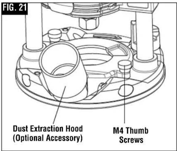
▶ The PR012 Router Dust Collection for Plunge Base
This dust extraction hood is designed for use the plunge base (PR111) when routing is done in the middle of the workpiece, such as when creating slots or routing patterns for inlays. If you have a shop vacuum system, you can attach the dust extraction hood for improved visibility, accuracy and utility, particularly in freehand routing.
To attach, position as shown and secure adapter to base with the thumbscrews provided (Fig. 21).
The dust extraction hood can also be installed with the hose outlet facing the front of the tool.
▶ Edgeforming Dust Extraction Hood RA1175
⚠ WARNING Do not reach in area of the bit while the router is ON or plugged in. To avoid entangling hoses, do not use this dust extraction hood at the same time as any other dust extraction hood.
This dust extraction hood (optional accessory) is used for dust collection when edge-forming (Fig. 22).
▼ATTACHING DUST EXTRACTION HOOD
You can attach the edge-forming hood in several places according to your needs or preferences. The dust hood is attached to the plunge base using two M4 thumb screws Two auxiliary holes are provided in the plunge base for attachment. Attach the dust extraction hood — over the router's sub-base — using the screws provided
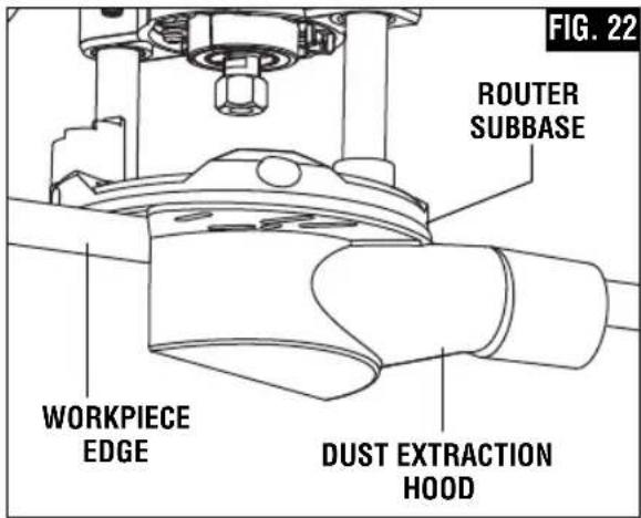
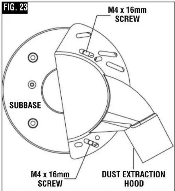
with the hood. Securely tighten the screws. (Figures 22 and 23).
Operating Instructions
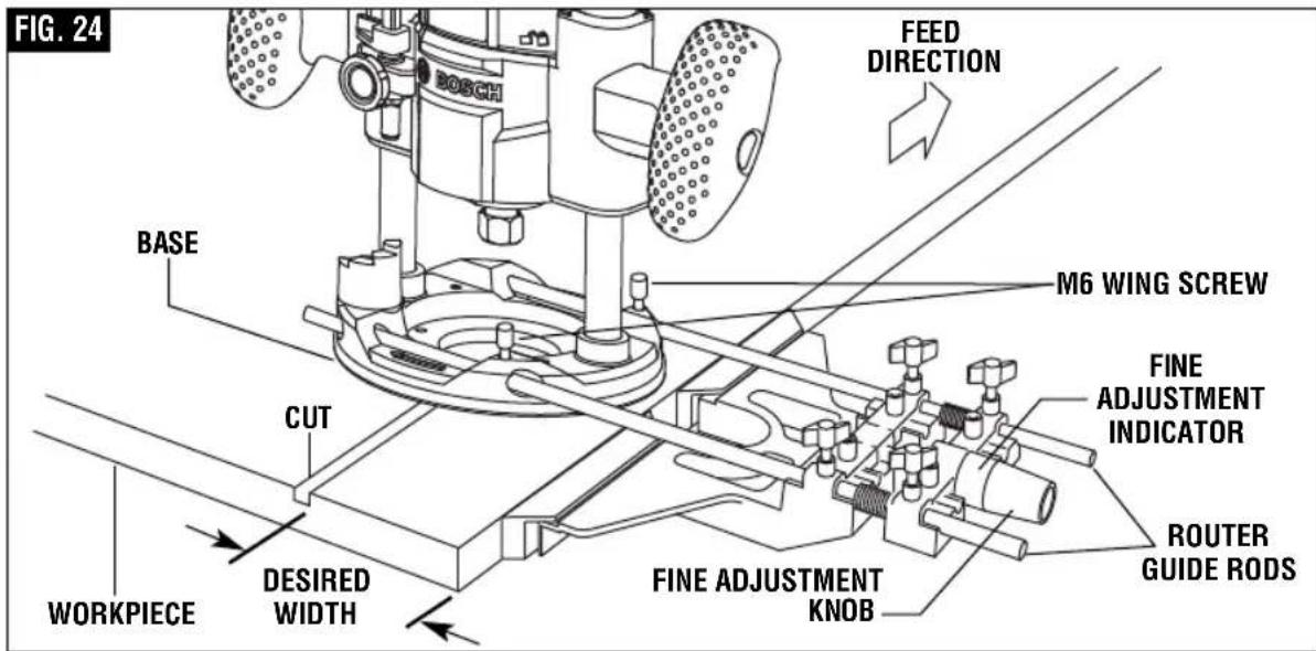
▶ Deluxe Router Guide
(Not included, available as accessory) The Bosch deluxe router guide is an optional accessory that will guide the router parallel to a straight edge or allow you to create circles and arcs. The deluxe router guide is supplied with two rods and screws to fasten the guide (Fig. 24). In addition, it features a fine adjustment knob and indicator for accurately positioning the edge guide relative to the bit. With the guide installed and adjusted, the
router should be fed normally, keeping the guide in contact with the edge of the workpiece at all times. The deluxe router guide may also be positioned directly under the router base for operations where a cut is needed close to or at the edge of the work.
The deluxe router guide includes a dust extraction hood and the VAC002 vacuum hose adapter.
For complete instructions on installation and operation, please refer to the instructions which are included with this accessory.
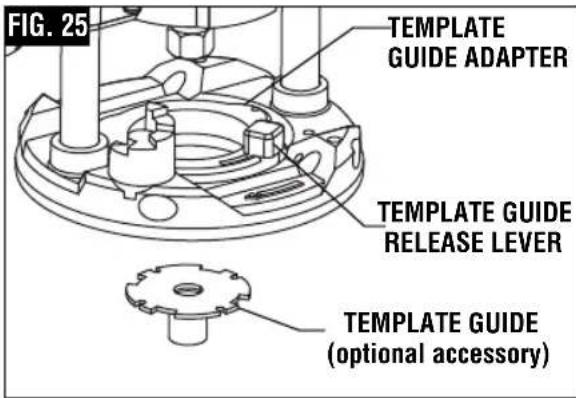
▶ Template Guides
This plunge base can also be used with the optional Bosch-exclusive quick-change template guide system, which firmly grips the guides with a spring-loaded ring. Unlike conventional threaded template guides, there is no threaded ring that can come loose while routing (Fig. 25).
▼ INSTALLING TEMPLATE GUIDE ADAPTER
(Not included, available as accessory)
Place template guide adapter over the holes in the center of the sub-base, and align the two threaded holes in the bottom of adapter with the countersunk holes in subbase. Fasten adapter with the screws provided.

Operating Instructions
Note that the adapter is reversible, so the release lever may be positioned as desired. (Fig. 26)
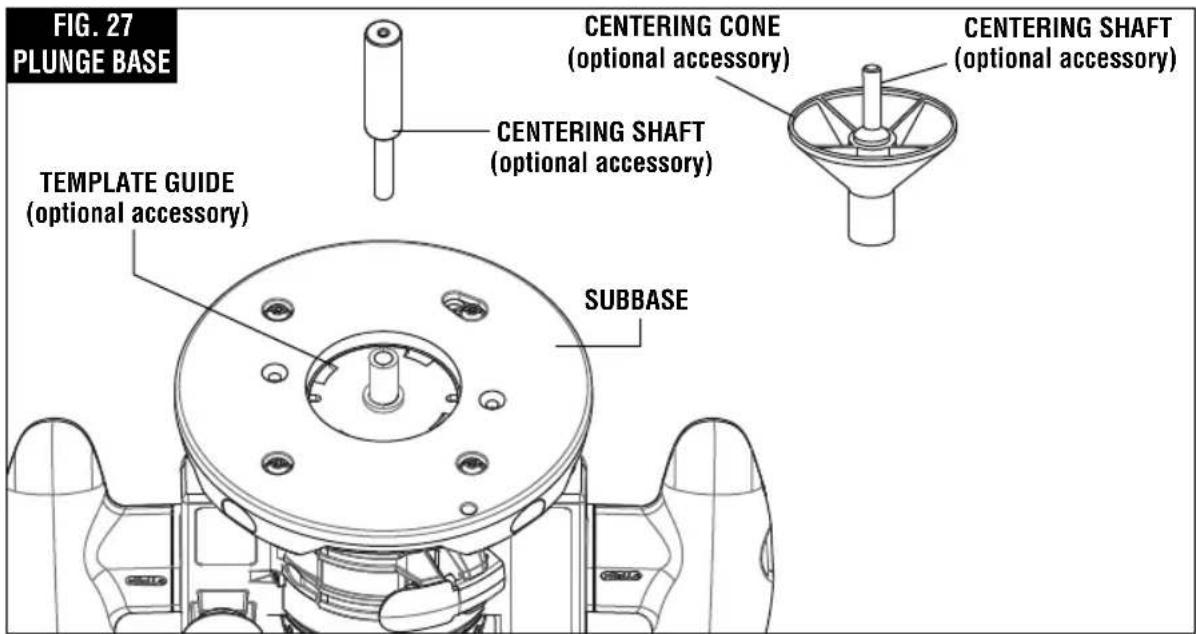
▼ CENTERING THE SUB-BASE OR TEMPLATE GUIDES
Your PR111 plunge base features the Bosch "Precision Centering Design". Its subbase is precisely centered at the factory. This positions the bit at the center of the subbase and optional template guides.
Precision centering allows you to use the edge of the subbase or template guides to closely follow jigs such as straight guides, templates, and dovetail fixtures without worrying about bit walk-off from the intended cut line for any reason, including the orientation of the router's handles relative to the jig.
To most precisely re-center the subbase or template guides, attach the subbase using the optional Bosch RA1151 Centering Device. Follow steps 1-8 (Fig. 27).
-
If a template guide is to be centered, Install the template guide adapter and template guide (optional attachments) as described elsewhere in this manual.
-
Loosen the four screws that hold
the subbase to the base.
- Prepare the Centering Device:
- Use narrow end of steel shaft. - When centering subbase or template guide that has opening of more than 1/2", slide the wide plastic sleeve over the steel shaft.
- Slide centering sleeve through the subbase or template guide and into collet. Tighten collet nut with fingers to put slight grip on centering cone.
- Lightly press centering sleeve into sub-base or template guide to center.
- Tighten the pan-head screws. Remove centering sleeve.
- The precision centering of the subbase or template guide is complete.
CENTERING CONE - Used when centering the subbase itself or wide template guides.
▼ MAXIMUM BIT/CUTTER SIZE FOR TEMPLATE GUIDES
When using a template guide, use only router bit with cutters that are 1/16" less than the internal diameter of the template guide, such as in the table below.
Operating Instructions
▼ USE WITH THREADED TEMPLATE GUIDES
Also available as an optional accessory is an additional adapter, the RA1100, that allows use of
conventional threaded template guides with the Bosch quick-release system.
Bosch Bushing External Internal Max Template Depth Diameter Diameter Bit/Cutter Guide Diameter
| A | B | B | ||
| RA1101 3/16” | 5/16” | 1/4” 3/16” | ||
| RA1103 9/64” | 5/16” | 17/64” 13/64” | ||
| RA1105 9/64” | 7/16” | 3/8” 5/16” | ||
| RA1107 5/16” | 7/16” | 3/8” 5/16” | ||
| RA1109 7/16” | 1/2” | 13/32” 11/32” | ||
| RA1111 3/16” | 5/8” | 17/32” 15/32” | ||
| RA1113 | 1/2” | 5/8” | 17/32” | 15/32” |
| RA1115 3/16” | 3/4” | 21/32” 19/32” | ||
| RA1117 | 31/64” | 13/16” | 5/8” | 9/16” |
| RA1119 | 31/64” | 1” | 25/32” | 21/32” |
| RA1121 7/16” | 1-3/8” 1-19/64” | 1-15/64” | ||
▶ Attaching a Vacuum / Dust Extractor Hose
The hose ports on the PR012, RA1175 and RA1054 will accept the typical nozzles from 35 mm vacuum cleaner hoses, such as the VX120 nozzle that is included with the Bosch VH-Series hoses.
To connect them to a 1-1/4 in. or 1-1/2 hose, the Bosch VAC002 or VAC024 vacuum hose adapters (both sold separately) can be used.
To connect them to a 2-1/2 in. hose, the Bosch VAC020 (sold separately) can be used.
Operating Instructions
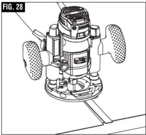
▶ PR006 Underscribe Attachment
(Available as optional accessory) The PR006 Underscribe Attachment is used to create precision-fit seams between two sheets of laminate (Fig. 28), such as stile and rail constructions and very large surfaces. It is attached to the bottom of the PR111 Plunge Base.
▼ INSTALLATION (FIG. 29)
- Remove rear screws used to hold subbase onto PR111 Plunge Base.
- Attach infeed side of PR006 to the Plunge Base using hex screw.
- Insert eccentric adjuster into pocket on outfeed side of PR006.
- Attach outfeed side of PR006 to the Plunge Base using hex screw.
▼ BIT INSTALLATION
- The recommend bit for use with the Underscribe Attachment is the Bosch 85213M with 1/8" cutting diameter.
- It should be installed according to the instructions on page 9.
▼ BIT HEIGHT ADJUSTMENT
After installing the bit, the height should be adjusted as follows:
- Lower bit until it just enters the recess that is machined in the underscribe attachment's aluminum plate.
- The tool is now ready for making a test cut.
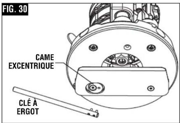
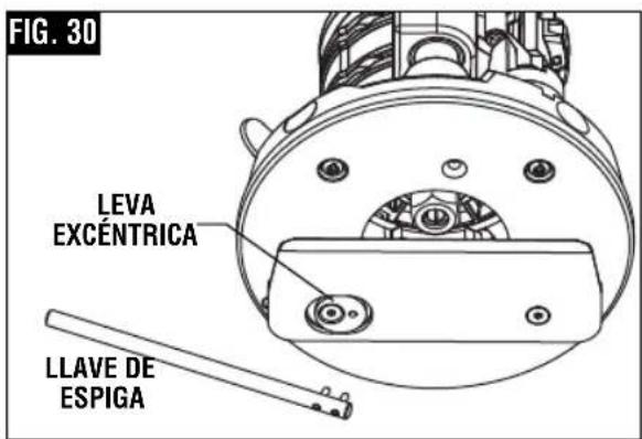
▼ FRONT-TO-BACK ADJUSTMENT
If necessary, the cutting point can be adjusted front-to-back as follows (Fig. 30):
- Loosen the two screws holding the aluminum plate.
- Using the pin wrench, adjust the eccentric adjuster as follows:
- For a tighter seam, turn the eccentric adjuster clockwise (as viewed from under the base)
natural_image
Technical line drawing of a mechanical device with multiple wheels and mounting base (no text or symbols)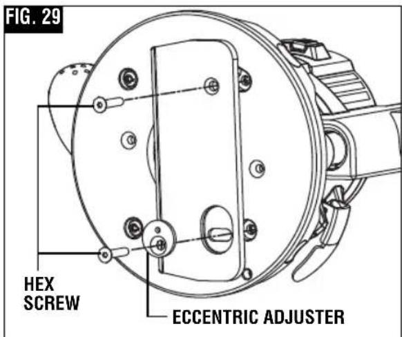
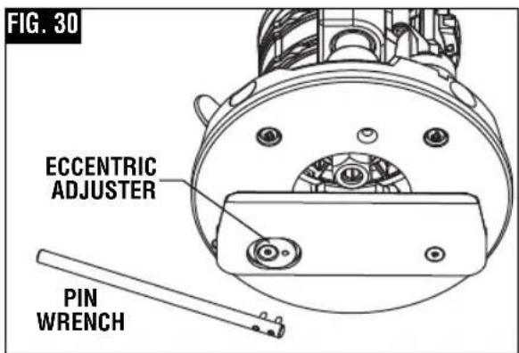
- For a looser seam, turn the eccentric adjuster counterclockwise, (as viewed from under the base)
- Retighten the screws
- Make a test cut
- Repeat steps 1-4 as necessary
Operating Instructions
▼ CREATING A SEAM
- To create a precision seam, make sure he guiding piece of laminate has a clean, straight edge, because it will serve as the guide for the underscribe attachment.
- Contact cement should be applied to the substrate core material and the guiding piece of laminate up to 1" from its guiding edge.
Maintenance
▶ Service
WARNING
Preventive main - tenance performed by unauthorized personnel may result in misplacing of internal wires and components which could cause serious hazard. We recommend that all tool service be performed by a Bosch Factory Service Center or Autho rized Bosch Service Station.
▼ TOOL LUBRICATION
Your Bosch tool has been properly lubricated and is ready to use. It is recommended that tools with gears be regreased with a special gear lubricant at every brush change.
▼ CARBON BRUSHES
The brushes and commutator in your tool have been engineered for many hours of dependable service. To maintain peak efficiency of the motor, we recommend every two to six months the brushes be examined. Only genuine Bosch replace ment brushes specially designed for your tool should be used.
▼ BEARINGS
Bearings which become noisy (due to heavy load or very abrasive material cutting) should be replaced at once to avoid overheating or motor failure.
▶ Cleaning
WARNING
To avoid accidents always dis connect the tool from the power supply before cleaning or performing any main tenance. The tool may be cleaned most effectively with compressed dry air. Always wear safety goggles when cleaning tools with compressed air.
Ventilation openings and switch levers must be kept clean and free of foreign matter. Do not at tempt to clean by inserting pointed objects through openings.
CAUTION
Certain cleaning agents and sol vents
damage plastic parts. Some of these are: gasoline, carbon tetrachloride, chlorinated cleaning solvents, ammonia and house hold detergents that contain ammonia.
Extension Cords
WARNING
If an extension cord is necessary, a cord
with adequate size conductors that is capable of carrying the current necessary for your tool must be used. This will prevent excessive voltage drop, loss of power or overheating. Grounded tools must use 3-wire extension cords that have 3-prong plugs and receptacles.
NOTE: The smaller the gauge number, the heavier the cord.
RECOMMENDED SIZES OF EXTENSION CORDS
120 VOLT ALTERNATING CURRENT TOOLS
| Tool's Ampere Rating | Cord Size in A.W.G. | Wire Sizes in mm ^2 | ||||||
| Cord Length in Feet | Cord Length in Meters | |||||||
| 25 | 50 | 100 | 150 | 15 | 30 | 60 | 120 | |
| 3-6 | 18 | 16 | 16 | 14 | 0.75 | 0.75 | 1.5 | 2.5 |
| 6-8 | 18 | 16 | 14 | 12 | 0.75 | 1.0 | 2.5 | 4.0 |
| 8-10 | 18 | 16 | 14 | 12 | 0.75 | 1.0 | 2.5 | 4.0 |
| 10-12 | 16 | 16 | 14 | 12 | 1.0 | 2.5 | 4.0 | - |
| 12-16 | 14 | 12 | - | - | - | - | - | - |
Accessories and Attachments
WARNING
The use of other acces sories and attach ments not specified in this manual may create a hazard.
- PR101 Fixed Base* ^++
- PR102 Edge Guide ^++
- PR110 Round Subbase for Threaded Template Guide
- PR111 Plunge Base *
- Router Bits
- Case ^++
- 17 mm Collet Nut Wrench* ††
- RA1151 Centering Device
-
PR006 Underscribe Attachment for Plunge Base
-
PR012 Dust Hood for Plunge Base
- RA1175 Edge-Forming Dust Hood for Plunge Base
- RA1054 Deluxe Router Guide for Plunge Base
- Vacuum Hoses
- Vacuum Hose Adapters
* Included with GKF125CEN
^+ Included with GKF125CEK
* Included with GKF125CEPK
natural_image
Technical illustration of a mechanical clamp assembly on a wooden base, showing a clamping mechanism (no text or symbols present)natural_image
Technical illustration of a mechanical assembly with a clamping tool and wooden base (no text or symbols)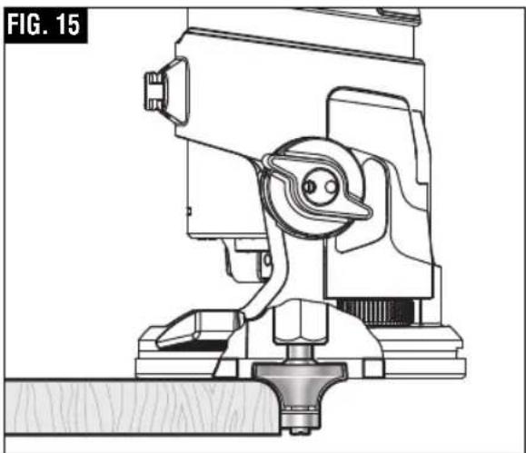
natural_image
Technical line drawing of a mechanical assembly (no text or symbols)natural_image
Technical line drawing of a mechanical device with internal components and a downward arrow indicating motion (no text or symbols)natural_image
Technical line drawing of a mechanical device with multiple wheels and mounting base (no text or symbols)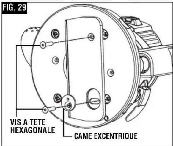
natural_image
Diagram of a mechanical device with labeled component A, showing no readable text or symbols beyond label and arrow.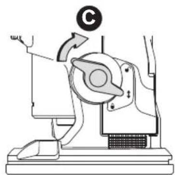
natural_image
Mechanical device diagram showing a rotating arm and base with a circular symbol (no text or labels)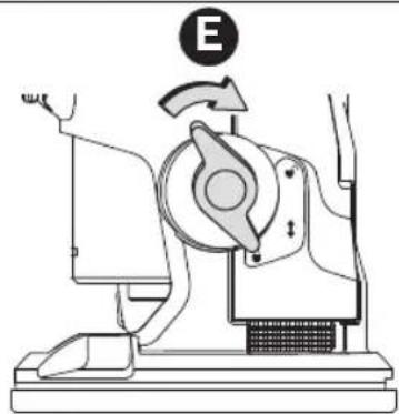
natural_image
Diagram of a mechanical device with labeled component E, showing no readable text or symbols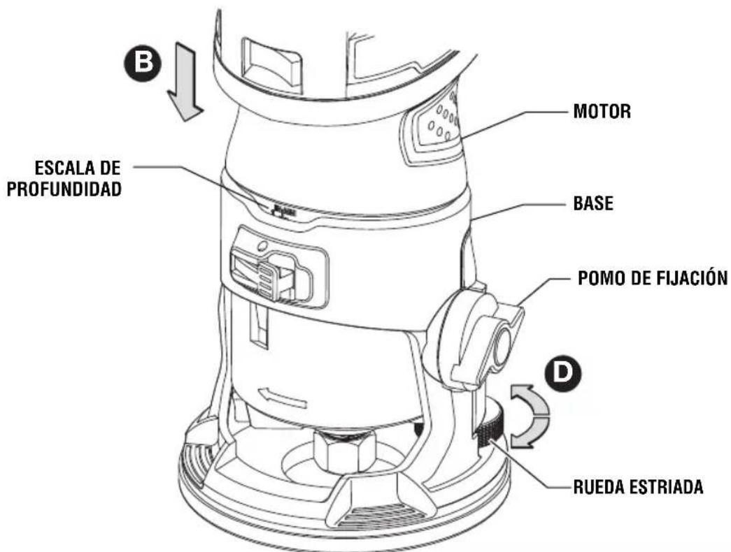
natural_image
Technical illustration of a mechanical clamp assembly on a wooden base, showing no text or symbols▼ CIRCUITERÍA CONSTANT RESPONSE™
natural_image
Technical illustration of a mechanical device with a tool and clamping mechanism, no visible text or symbolsnatural_image
Technical line drawing of a mechanical device with no visible text or symbolsnatural_image
Technical line drawing of a mechanical device with internal components and a downward arrow indicating motion (no text or symbols)natural_image
Technical line drawing of a mechanical device with multiple wheels and mounting base (no text or symbols)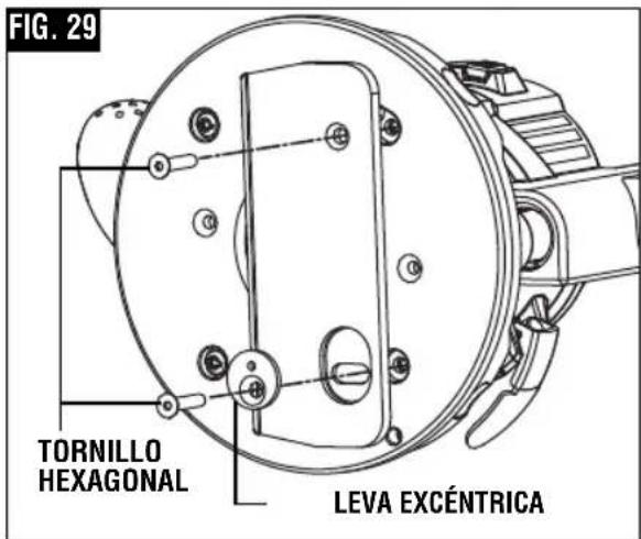
Robert Bosch Tool Corporation ("Seller") warrants to the original purchaser only, that all BOSCH portable and benchtop power tools will be free from defects in material or workmanship for a period of one year from date of purchase. SELLER'S SOLE OBLIGATION AND YOUR EXCLUSIVE REMEDY under this Limited Warranty and, to the extent permitted by law, any warranty or condition implied by law, shall be the repair or replacement of parts, without charge, which are defective in material or workmanship and which have not been misused, carelessly handled, or misrepaired by persons other than Seller or Authorized Service Station. To make a claim under this Limited Warranty, you must return the complete portable or benchtop power tool product, transportation prepaid, to any BOSCH Factory Service Center or Authorized Service Station. For Authorized BOSCH Power Tool Service Stations, please refer to your phone directory.
THIS LIMITED WARRANTY DOES NOT APPLY TO ACCESSORY ITEMS SUCH AS CIRCULAR SAW BLADES, DRILL BITS, ROUTER BITS, JIGSAW BLADES, SANDING BELTS, GRINDING WHEELS AND OTHER RELATED ITEMS.
ANY IMPLIED WARRANTIES SHALL BE LIMITED IN DURATION TO ONE YEAR FROM DATE OF PURCHASE. SOME STATES IN THE U.S., SOME CANADIAN PROVINCES DO NOT ALLOW LIMITATIONS ON HOW LONG AN IMPLIED WARRANTY LASTS, SO THE ABOVE LIMITATION MAY NOT APPLY TO YOU.
IN NO EVENT SHALL SELLER BE LIABLE FOR ANY INCIDENTAL OR CONSEQUENTIAL DAMAGES (INCLUDING BUT NOT LIMITED TO LIABILITY FOR LOSS OF PROFITS) ARISING FROM THE SALE OR USE OF THIS PRODUCT. SOME STATES IN THE U.S. AND SOME CANADIAN PROVINCES DO NOT ALLOW THE EXCLUSION OR LIMITATION OF INCIDENTAL OR CONSEQUENTIAL DAMAGES, SO THE ABOVE LIMITATION OR EXCLUSION MAY NOT APPLY TO YOU.
THIS LIMITED WARRANTY GIVES YOU SPECIFIC LEGAL RIGHTS, AND YOU MAY ALSO HAVE OTHER RIGHTS WHICH VARY FROM STATE TO STATE IN THE U.S., PROVINCE TO PROVINCE IN CANADA AND FROM COUNTRY TO COUNTRY.
THIS LIMITED WARRANTY APPLIES ONLY TO PORTABLE AND BENCHTOP ELECTRIC TOOLS SOLD WITHIN THE UNITED STATES OF AMERICA, CANADA AND THE COMMONWEALTH OF PUERTO RICO. FOR WARRANTY COVERAGE WITHIN OTHER COUNTRIES, CONTACT YOUR LOCAL BOSCH DEALER OR IMPORTER.
GARANTIE LIMITÉE DES OUTILS ÉLECTRIQUES PORTATIFS ET D'ÉTABLI BOSCH
© Robert Bosch Tool Corporation 1800 W. Central Road Mt. Prospect, IL 60056-2230
Exportado por: Robert Bosch Tool Corporation Mt. Prospect, IL 60056-2230, E.U.A.