
APZ 600-270 - Compressor Airpress - Free user manual and instructions
Find the device manual for free APZ 600-270 Airpress in PDF.

| Product type | Piston compressor with tank |
| Brand | Airpress |
| Model | APZ 600-270 |
| Dimensions (L x W x H) | 70 x 154 x 158 cm |
| Weight | 248 kg |
| Power supply | 400 V / 3 phases / 50 Hz |
| Motor power | 4 kW (5.5 hp) |
| Tank capacity | 270 L |
| Air flow | 650 L/min (39 m³/h) |
| Maximum pressure | 10 bar (143 psi) |
| Noise level | 68 dB(A) |
| Pump speed | 900 rpm |
| Oil type | Airpress synthetic oil for piston compressors |
| Maintenance | Oil change every 1000 h, belt check every 300 h, air filter cleaning every 300 h |
| Safety | Emergency stop, safety valve, pressure switch, motor thermal protection |
| Warranty | According to general terms and conditions of sale |
| Standards | Directive 2006/42/EC, CE marking |
| Included accessories | Lifting straps, pressure gauge, drain valve |
Frequently Asked Questions - APZ 600-270 Airpress
User questions about APZ 600-270 Airpress
0 question about this device. Answer the ones you know or ask your own.
Ask a new question about this device
Download the instructions for your Compressor in PDF format for free! Find your manual APZ 600-270 - Airpress and take your electronic device back in hand. On this page are published all the documents necessary for the use of your device. APZ 600-270 by Airpress.
USER MANUAL APZ 600-270 Airpress
EN | Hearing, sight and respiratory protection must be worn.
EN Warning, hot surfaces.
Please read this operation and maintenance manual carefully in all its parts before operating the compressor. This machine has been tested in accordance with the Machine Directive 2006/42/EC and its further changes (see Declaration of Conformity).
We thank you for choosing our product and invite you to read this manual thoroughly. In it, you will find all the necessary information for the proper use of the machine. You are kindly requested to follow the instructions provided here and to read carefully this manual in its entirety. Please ensure that it is stored in a safe place and remains unaltered. We reserve the right to modify the content of this manual without prior notice to include any variations or improvements. Any reproduction or translation of this manual is strictly prohibited without prior consent from the owner.
WARRANTY
The liability for the warranty is determined by the general terms in force. This warranty entitles the Purchaser only to a replacement of defective parts. However, the warranty will be voided it the machine has been improperly used or tampered with by individuals not authorized by us, or if non-compliant technical components have been used.
SAFETY SYMBOLS
Below is a brief legend explaining the symbols used:

DANGER: Alerts the operator to situations that may endanger people's safety or cause injury or death.

ATTENTION: Draws attention to issues that affect the efficiency of the machine but do not compromise people's safety.

IMPORTANT: Highlights important general information that does not affect either the safety of individuals or the proper functioning of the machine.
1. INTRODUCTION
This manual is intended for the machine and to the range of machines mentioned in the casing. It serves as your guide to for installation, use, and maintenance of the compressor you have purchased.
This manual must always be kept in a safe place and be easily accessible. It is an integral part of the compressor.
1.1. MACHINE DOCUMENTATION
When the machine is delivered (within the EU), you will receive:
• This operation and maintenance manual.
• CE conformity mark on the machine.
• CE declaration of conformity.
When the machine is delivered, check that the product is intact and that everything is in accordance with the contract.
Dispose of the packing material according to the applicable laws.
1.2. APPLICATION
This compressor with a piston alternate group has been designed and built solely for producing compressed air.

Do not use the machine for any purpose other than what it has been specifically designed for.
1.3. DESCRIPTION
The machine described in this manual is a compressor with a piston alternating group and a belt drive.
There are different versions available: with or without an air tank, with or without a dryer.
1.4. IDENTIFICATION
To identify the machine when requesting spare parts or assistance, always refer to the machine data on the CE mark plate located on the compressor.
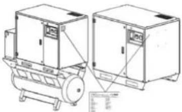
natural_image
Technical line drawing of two industrial equipment units with no visible text or symbolsFig.1
2. OPERATING CONTROLS AND COMPONENTS
The figure below represents the machine and the main parts it is composed of.
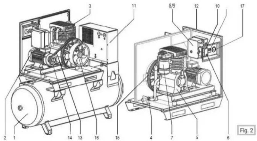
1 Air tank
2 Electric motor
3 Compressor head
4 Retaining valve
5 Oil tank
6 Emergency stop
7 Air filter
8 Electrical system
9 Hour meter
10 Pressure switch
11 Dryer
12 Casing
13 Straps
14 Pulley
15 Pulley
16 Electric fan
17 Manometer
3. GENERAL INFORMATION
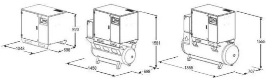
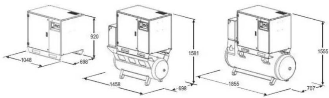
3.1. DIMENSIONS
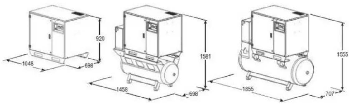
Fig. 3
3.2. TECHNICAL FEATURES (VERSION WITH AIR TANK)
SKU
COMPRESSOR
TANK
PISTON
CYLINDER
PRESSURE
| 34351-270 34651-270S | ||
| MOTOR | TYPE APZ600-270 APZ900-270S | |
| litres 270 L 270 L | ||
| CIL 2B 2B | ||
| L/min 650 850 | ||
| CFM 23 30 | ||
| m3/h 39 49.8 | ||
| bar 10 10 | ||
| psi 143 143 | ||
| Hp/Cv 5.5 7.5 | ||
| Kw | 4 | |
| VOLTAGE | V/ph 400/3 | 400/3 |
| RPM | RPM | 900 |
| WEIGHT | Kg | 248 307 |
| NOISE | Lbs 546 677 | |
| DRYER | dB(A) | 68 68 |
| Dryer - | - | |
| DIMENSIONS (cm) | A x B x h (cm) | 70 x 154 x 158 |
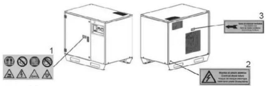
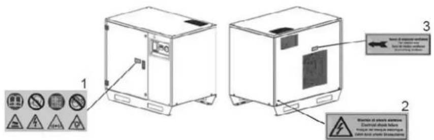
3.3. WARNINGS AND INFORMATION LABELS AND TAGS
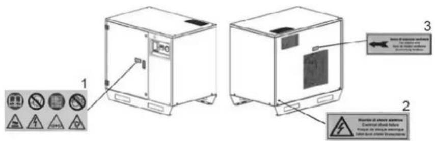
Fig. 4
1 General warnings
2 Electric system hazards
3 Direction of motor rotation
4. SAFETY PRECAUTIONS


Carefully read this manual in its entirety before using the compressor.
In case of necessity, contact our technical assistance team.
Do not attempt repairs. If repairs are made by unqualified personnel, the safety level of the machine could be compromised.
Carry out all work and maintenance tasks according to the regulations regarding hygiene and workplace safety.
When handling the compressor, use appropriate equipment as explained in Section 7 "HANDLING THE COMPRESSOR".
4.1. OPERATOR WORKING RULES

The operations described in this section must be carefully followed when using the compressor.
Always wear personal protective equipment in accordance with the laws regarding hygiene and worker safety (it is advisable to wear protective glasses).
During maintenance operations, please dispose of waste properly and follow local regulations.
The labels and the tags situated on the machine must always be kept readable.
Do not perform repairs or maintenance when the machine is powered.
Do not approach to any components of the system with heat sources or flames.
Do not use the machine for purposes other than its intended use.
It is prohibited to use high-pressure water jets (pressure washer) to clean the compressor.
When dismantling the machine, observe the regulations in force in the country where this operation is carried out (especially regarding oil disposal).
4.2. SAFETY REGULATIONS
Only adults who are responsible and have read this manual are authorized to operate the machine.
When the machine is running, do not remove the safety protections or casing and do not touch moving parts.
Do not unplug the electrical plug by pulling the cable. Do not step on it or crush it with heavy objects or sharp edges.
Do not handle the compressor while it is connected to the electrical system or when the air tank is under pressure.
If the compressor is used with electrical extensions, ensure that the extension cord is suitable for the intended use.
Before using the compressor, check for any visible damage to the protections or other parts; if damaged, qualified personnel must repair or replace them.
Only use original spare parts; using NOT ORIGINAL spare parts will void the warranty. Use the compressor with the rated voltage as indicated on the CE mark plate (see Fig. 1).
Do not wash the casings or the plastic parts with corrosive liquids.
If the compressor produces strange noises or vibrations, stop it immediately and, if necessary, request assistance.
Do not modify the compressor without the constructor's authorization.
Do not direct the air stream towards people or animals. If the compressor is used for painting, keep it away from open flames; ensure there is adequate air ventilation (see Section 5.1 "POSITIONING" and Fig. 5); wear safety equipment according to the applicable regulations.
5. START-UP

Before starting the compressor, carefully read the entire manual.
Before using the compressor, check that everything corresponds to the specifications requested during the purchase.
5.1. POSITIONING
For the proper operation of the compressor, it must be placed in an appropriate location with the following features:
The room temperature must be between 5°C and 45°C.
At temperature lower than 5°C the working conditions of the fluids are altered, which may cause seizures.
At temperatures higher than 45°C, the exchanger may not properly cool the oil in the circuit, activating the temperature safety device.
Do not use the compressor in explosion-prone areas or where there is a high risk of fire. Use it only in areas with good air circulation and far from inflammable materials.
To facilitate natural air exchange, the room should have openings to the outside near both the floor and ceiling (see Fig. 5).
The room where the compressor is used should not contain dust, as it can clog the filter and cause malfunction.
For easier maintenance and proper air circulation, it is recommended to leave enough free space around the compressor.
The flooring supporting the compressor must be stable and flat.
The compressor does not require fixed vibration-damping on the standing feet due to its design.
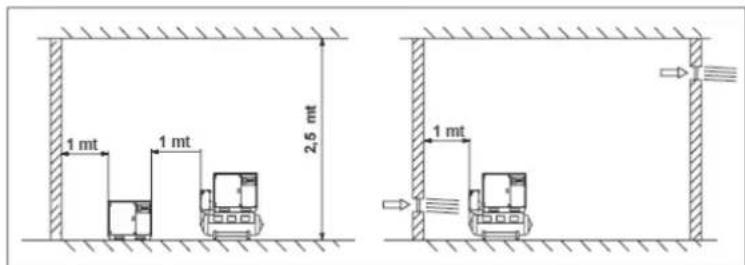
Fig. 5
5.2. CONNECTION TO THE ELECTRICITY NETWORK

The compressor must be connected to the electricity network by qualified personnel according to the accident prevention regulation EN 60204.
The compressor and, if supplied, the dryer must be:
• Properly grounded to protect the operator from electric shocks.
• The supply voltage must correspond to the one shown on the CE tag (see Fig. 1).
• The electrical supply must be provided with a cable whose cross-section is suited to the machine's power.
• Never use the plug of the connection cable as a switch. To start the motor, use the appropriate magneto-thermal switch with the proper amperage.
• The following table describes the values of the conductor section, depending on the machine power:
| Power [Kw - Hp] | Rated voltage [400 V] | Rated voltage [230 V] |
| 4 - 5.5 | 1.5 mm^2 | 2.5 mm^2 |
| 5.5 - 7.5 | 2.5 mm^2 | 4 mm^2 |
| 7.5 - 10 | 4 mm^2 | 6 mm^2 |
| 11 - 15 | 4 mm^2 | 10 mm^2 |
To avoid short-circuits, protect the electrical network with appropriate fuses and a magneto-thermal switch.
The following table describes the features of the magneto-thermal switch and fuses to use according to the machine's power:
| Power [Kw - Hp] | Rated voltage [400 V] | Rated voltage [230 V] | ||
| Magneto-thermal switch | Fuses | Magneto-thermal switch | Fuses | |
| 4 - 5.5 (D.O.L) | 20 A | - | 25 A | - |
| 5.5 - 7.5 | 25 A | - | 20 A | 25 A |
| 5.5 - 7.5 (Y - Δ) | 25 A | 25 A | 32 A | 36 A |
| 25 A | 30 A | 40 A | - | |
| 7.5 - 10 (Y - Δ) | 25 A | 30 A | 40 A | 40 A |
| 11 - 15 (Y - Δ) | 40 A | 40 A | 63 A | 63 A |
EXTENSIONS
If the connection is carried out using extensions, use grounded extensions. The section of the extension cable must be suitable for the electric current absorbed. Do not crush or damage the cable.
The cable section of three-phase compressor model must be proportional to the length – see the following table:
| Kw - Hp | 220/230 V | |
| 50/60 Hz | ||
| 3 ph | 380/400 V | |
| 50/60 Hz | 4 mm ^2 | 2.5 mm ^2 |
| 3 ph | 6 mm ^2 | 2.5 mm ^2 |
| 4 - 5.5 | 10 mm ^2 | 4 mm ^2 |
| 5.5 - 7.5 | 10 mm ^2 | 6 mm ^2 |
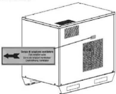
ROTATION DIRECTION CHECK
At the back of the compressor, check through the grid if the belt rotation matches the direction indicated on the adhesive in Fig. 6. If the rotation is incorrect, stop the compressor immediately and reverse the poles.
Always use pneumatic pipes that meet the required maximum pressure and have the appropriate cross-sections.
For ground compressor with an air tank or dryer, connect the machine to the proper 34 " coupling in the pneumatic system (see Fig. 7). The diameter of the connection must be equal to or larger than the compressor outlet.
Install two spherical taps of adequate capacity between the compressor and the pneumatic system.
natural_image
Technical line drawing of a mechanical assembly with three views: front view, side view, and top view (no text or symbols)Fig. 7
6. HOW TO USE THE COMPRESSOR

Only a qualified expert is allowed to carry out the first starting of the compressor (functional test).
6.1. CALIBRATION OF THE PRESSURE SWITCH
!
The calibration of the pressure switch allows to regulate the maximum pressure.
The pressure switch must be calibrated when there is pressure in the system. The calibration is carried out through the following steps:
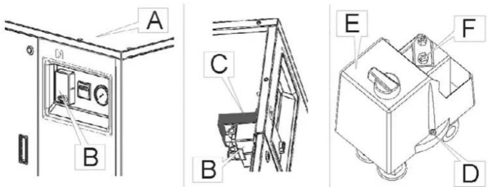
Fig. 8
| 1 | Operate the automatic stop of the motor, without using the emergency stop button. |
| 2 | Cut off the electric power to the system using the wall switch located outside the compressor. |
| 3 | Remove the screws, lift the upper panel (Pos. A of Fig. 8), and identify the pressure switch (Pos. B). |
| 4 | Remove the support pressure (Pos. C). Unscrew the pressure switch lid retaining screw (Pos. D) and remove the lid (Pos. E). |
| 5 | To regulate the maximum pressure, turn the screw (Pos. F). Turning clockwise increases the pressure, whereas turning counterclockwise decreases it. |
| 6 | Reassemble the components. Power on the machine using the external wall switch and then the switch located on the machine. Start the compressor to check the calibration. |
| Never exceed the maximum pressure value indicated in the Section 3.2 “TECHNICAL FEATURES”. | |
7. HANDLING
Before handling the compressor, ensure that all parts are properly fixed. Depending on the configuration of the compressor, with or without an air tank, during the transport, the handling of the compressor must be carried out at follows:
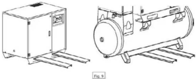
natural_image
Technical line drawings of industrial equipment, one showing a cabinet and the other a cylindrical tank with mounting brackets (no text or symbols)A compressor without an air tank must be lifted using a pallet jack or pallet truck with appropriate load capacity.
A compressor with an air tank must be lifted in the same way (see Fig. 9). The weight is shown in the Section 3.2 "TECHNICAL FEATURES".
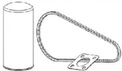
8. MAINTENANCE

Before performing any maintenance tasks, read this section carefully.
Maintenance operations must be carried out by qualified personnel. Before performing any maintenance, ensure that the mains supply is de-energized. Carrying out only the maintenance operations described in this manual is essential; failing to follow this may pose serious risks to unqualified operators and could affect the overall performance and reliability of the machine. When replacing components, always use original spare parts. Nameplates and adhesive plates should not be removed during operation or maintenance.
natural_image
Simple line drawing of a cylindrical object next to a coiled cable with mounting flange (no text or symbols)Fig. 10
8.1. CLEANING
For overall cleaning of the compressor, use dry air jets and wet cloths. Do not use solvents, petrol, or water jets.
8.2. PLANNED MAINTENANCE
The following table outlines essential maintenance tasks to keep the compressor in good condition.
| EVERY 50 HOURSCheck the oil level with the transparent cap (it should be halfway on the red point).Discharge the condensation using the tap at the bottom part of the tank. | EVERY 300 HOURS | EVERY 500 HOURS | EVERY 1000 HOURS |
| Security valve control. | Air cartridge replacement. | Total oil replacement. | |
| Tension belt control. | General cleaning. | Belt and pulley control. | |
| Oil leak control. | Tube tightening check. | ||
| Air filter cleaning. | Electric connection check. |
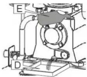
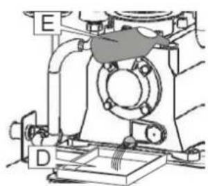
8.2.1. OIL CHANGE
Read Section 8.2 "PLANNED MAINTENANCE" before changing the oil. To change the oil or fill the tank, follow these steps:
| 1 | Disconnect the compressor completely from the power supply. |
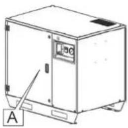
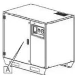
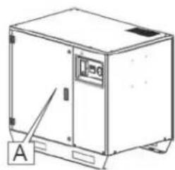
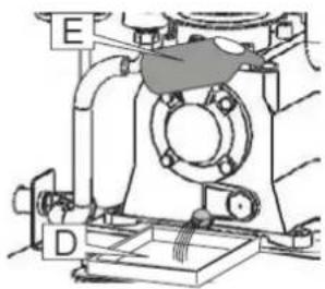
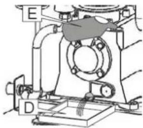
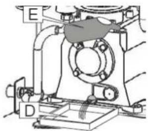
| 2 | Open the door (Pos. A, Fig. 11). |
| 3 | Remove the oil plug (Pos. B, Fig. 11). |
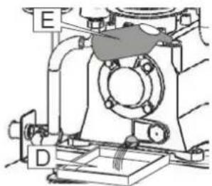
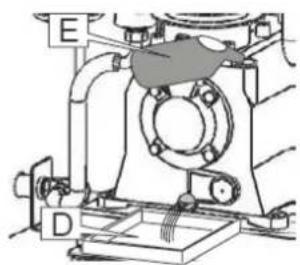
| 4 | Remove the cap (Pos. C, Fig. 11) and place a suitable collection container (Pos. D) underneath. The amount of oil in the tank may vary. |
| 5 | Close the drain valve (Pos. C) and top up with new oil, such as Airpress oil, through the opening (Pos. E). |
| 6 | Check the oil level with the oil level indicator (Pos. F, Fig. 11) to ensure the maximum fill level is not exceeded. |
| 7 | Close the door and secure it with the two locks provided. |
natural_image
Line drawing of a mechanical device with labeled component A (no text or symbols beyond labels)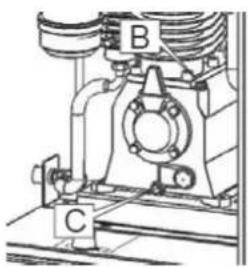
natural_image
Technical line drawing of a mechanical assembly with labeled components A, B, and C (no text or symbols beyond labels)Fig. 11

natural_image
Technical diagram of a mechanical assembly with labeled components (E, D), no readable text or symbols present.8.2.2. OIL
A synthetic coolant and lubricant for compressors, such as Airpress oil, should be used to top up the reservoir or for a complete oil change of the compressor.
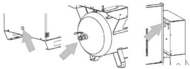
8.2.3. RETAINING VALVE REPLACEMENT
Read Section 8.2 "PLANNED MAINTENANCE" before starting the valve replacement.
To replace the retaining valve, follow these steps:
1 Disconnect from the mains.
2 Completely empty the tank using the condensate tap.
3 Unscrew the cap manually (Pos. B, Fig.12), remove the cartridge, and replace it with a new one.
4 Unscrew the hexagonal tap (Pos. B) with a wrench (Pos. C).
5 Clean the rubber floppy disk and centre accurately and replace if necessary (Pos. D).
natural_image
Technical line drawing of a rectangular industrial machine with labeled components (no text or symbols beyond labels)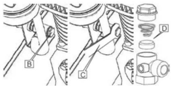
Fig. 12
8.2.4. AIR FILTER CARTRIDGE REPLACEMENT (MODELS APZ 600 & APZ 900)
Read Section 8.2 "PLANNED MAINTENANCE" before starting the replacement. To replace the air filter cartridge, follow these steps:
1 Disconnect from the mains.
2 Completely empty the tank using the condensate tap.
3 Open the door with the equipped key (Pos. A, Fig. 13).
4 Unscrew the cap (Pos. B), remove the cartridge, and replace it with a new one.
5 Replace the filter cap and secure it.
natural_image
Line drawing of a mechanical device with labeled component A (no text or symbols beyond label)
natural_image
Technical line drawing of a mechanical spring assembly with labeled component B (no text or symbols beyond label)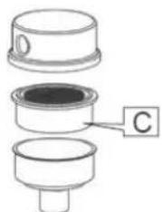
natural_image
Cross-sectional diagram of a mechanical component with labeled part C (no text or symbols beyond label)Fig. 13
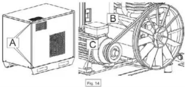
8.2.5. BELT REPLACEMENT (MODELS APZ 600 & APZ 900)
To replace the transmission belts, follow these steps:
1 Disconnect from the mains and unscrew the panel retaining screws (Pos. A, Fig. 15) to remove it.
2 Check the wear of the belts (Pos. B).
3 Using an open-end wrench, loosen the belt tightener (Pos. C).
4 Remove the worn belt (Pos. B) and replace it with a new one.
5 Tighten the belts using the tightener (Pos. C).
6 Put the panel back in place fixing the screws (Pos. A).
natural_image
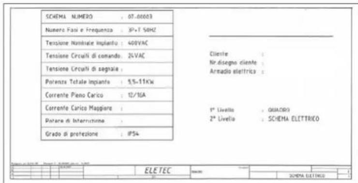
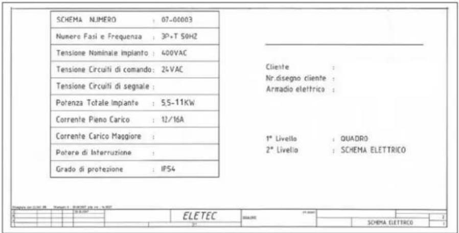
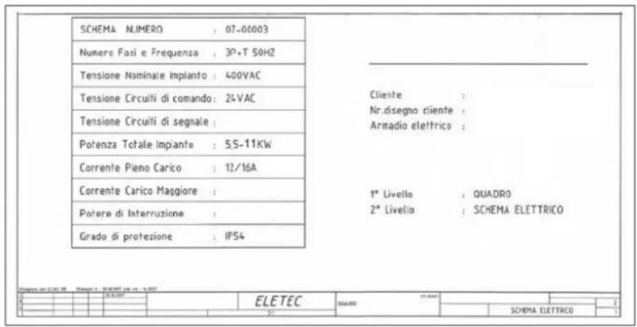
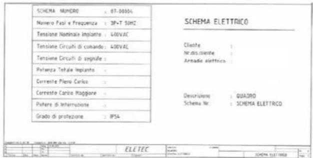
Technical line drawing of a mechanical device with labeled components A, B, and C, showing internal components and assembly (no text or symbols beyond labels)9. ELECTRICAL DIAGRAMS
The following is the legend and the electrical systems.
| PROBLEM |
| The compressor does not start. |
| POSSIBLE CAUSES |
| - The electric supply is missing.- The line voltage is not the one indicated on the CE mark plate.- Thermal protection of the motor is on.- The compressor is under pressure.- The pressure switch is faulty. |
| REMEDIES |
| - Check the connection to the electric system.- Reactivate the motor thermal protection (by a specialized technician).- Empty the tank.- Check the electro-mechanical efficiency of the pressure switch. |
| PROBLEM |
| Low or no output, pressure does not increase. |
| POSSIBLE CAUSES |
| - The aspiration filter is clogged.- Loosened or worn belts.- Clogged retaining valve.- Mechanical problem with the pumping group. |
| REMEDIES |
| - Clean or replace the air filter.- Apply tension to the belts or replace them.- Disassemble and clean the retaining valve and, if necessary, replace it.- Revise pumping group. |
| PROBLEM |
| The compressor starts with difficulty and the thermal protection is often on. |
| POSSIBLE CAUSES |
| - The electrical voltage of the employee at the motor terminals is insufficient.- Loss of thermostat calibration. |
| REMEDIES |
| - Check the line voltage.- In three-phase motors, measure the absorption of each single phase.- Replace the thermal protection in case of fault.- Remove the belts and check the pumping group. |
| PROBLEM |
| Oil consumption or leaks. |
| POSSIBLE CAUSES |
| - Excessive consumption.- Leaks in the system. |
| REMEDIES |
| - Revise the pumping group.- Check the tube and joint seals. |
| PROBLEM |
| Vibrations and noises. |
| POSSIBLE CAUSES |
| - Loosen or worn compressor components.- Head discharge tube break.- Wom pumping group.- Unstable compressor. |
| REMEDIES |
| - Check the fixing of the components.- Replace the discharge tube.- Check the pumping group.- Ensure the stability of the compressor on the floor. |
natural_image
Technical line drawing of two industrial equipment units with no visible text or symbols2. ROZMIESZCZENIE ELEMENTÓW STERUJĄCYCH I PODZESPOŁÓW
natural_image
Technical line drawing of a mechanical assembly with directional arrows indicating motion (no text or symbols)6. JAK UŻYWAĆ SPREŻARKI

natural_image
Simple line drawing of a cylindrical container and a coiled cable with mounting flanges (no text or symbols)Fig. 10
8.1. CZYSZCZENIE SPREŻARKI
natural_image
Technical line drawing of a mechanical device with labeled components (no text or symbols beyond labels)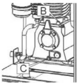
natural_image
Mechanical assembly diagram showing a bearing housing with labeled components A, B, and C (no text or symbols beyond labels)Fig. 11
natural_image
Technical diagram of a mechanical assembly with labeled components (E, D), no readable text or symbols present.8.2.2. TABELA OLEJU
Fig. 12
8.2.4. WYMIANA WKŁADU FILTRA POWIETRZA MOD. APZ 600 & APZ 900
natural_image
Technical line drawings of industrial equipment including a box labeled A and a wheel with labeled components B, C (no text or symbols beyond labels)Fig. 14
9. SCHEMATY ELEKTRYCZNE
natural_image
Technical line drawing of two industrial equipment units with no visible text or symbols2. LAGE DER BEDIENELEMENTE UND KOMPONENTEN
natural_image
Technical line drawing of a mechanical assembly with three views: front view, side view, and top view (no text or symbols)6. VERWENDUNG DES KOMPRESSORS

natural_image
Technical line drawings of industrial equipment components, one showing a cabinet and the other a cylindrical tank (no text or symbols)natural_image
Simple line drawing of a cylindrical object next to a coiled cable with mounting flange (no text or symbols)Fig. 10
8.1. KOMPRESSORREINIGUNG
natural_image
Line drawing of a mechanical device with labeled component A (no text or symbols beyond labels)
natural_image
Technical line drawing of a mechanical assembly with labeled components A, B, and C (no text or symbols beyond labels)Fig. 11
natural_image
Technical diagram of a mechanical assembly with labeled components (E and D), no readable text or symbols present.8.2.2. ÖLTABELLE
natural_image
Line drawing of a rectangular industrial machine with labeled components (no text or symbols beyond labels)
Fig. 12
8.2.4. AUSTAUSCH DER LUFTFILTERPATRONE - MODELLE APZ 600 & APZ 900
natural_image
Line drawing of a rectangular industrial machine with labeled component A (no text or symbols beyond label)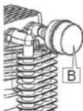
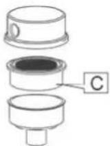
Fig. 13
8.2.5. AUSTAUSCH DES RIEMENS (APZ 600 & APZ 900)
natural_image
Technical line drawing of a mechanical device with labeled components A, B, and C, showing front and side views (no text or symbols beyond labels)natural_image
Technical line drawing of two industrial equipment units with no visible text or symbols1 Drukvat
2 Elektrische motor
3 Pomp
4 Terugslagklep
5 Oliereservoir
6 Noodstop
7 Luchtfilter
8 Elektrische schakelkast
9 Urenteller
3.3. WAARSCHUWINGS- EN INFORMATIELABELS
5.3. AANSLUITING OP HET PNEUMATISCHE SYSTEEM

natural_image
Technical line drawing of a mechanical assembly with no visible text or symbols6. GEBRUIK VAN DE COMPRESSOR

natural_image
Technical line drawings of industrial equipment components, one showing a cabinet and the other a cylindrical tank (no text or symbols)natural_image
Technical line drawing of a cylindrical object and a coiled cable with mounting flange, labeled Fig. 10 (no text or symbols on the diagram itself)8.1. COMPRESSOR REINIGEN
natural_image
Line drawing of a mechanical device with labeled component A (no text or symbols beyond labels)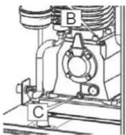
natural_image
Mechanical assembly diagram showing a bearing housing with labeled components A, B, and C (no text or symbols beyond labels)Fig. 11
natural_image
Technical diagram of a mechanical assembly with labeled components (E and D), no readable text or symbols present.8.2.2. OLIETABEL
natural_image
Line drawing of a mechanical device with labeled components (no text or symbols beyond labels)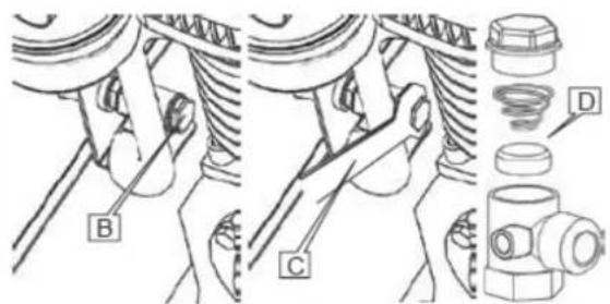
Fig. 12
8.2.4. HET LUCHTFILTERELEMENT VERVANGEN - APZ 600 & APZ 900 MODELLEN
natural_image
Technical line drawings of industrial equipment including a box labeled A and a wheel assembly with labeled components B, C, and a captioned figure (Fig. 14)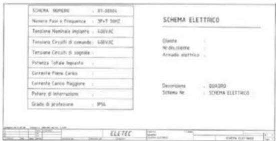
10. PROBLEEMOPLOSSING
natural_image
Technical line drawing of two industrial equipment units with no visible text or symbols2. POSITION DES COMMANDES ET DES COMPOSANTS
natural_image
Technical line drawing of a mechanical assembly with three views: front view, side view, and top view (no text or symbols)6. COMMENT UTILISER LE COMPRESSEUR

natural_image
Technical line drawings of industrial equipment components, one showing a cabinet and the other a cylindrical tank (no text or symbols)natural_image
Line drawing of a cylindrical object next to a coiled cable with mounting flange (no text or symbols)Fig. 10
8.1. NETTOYAGE
natural_image
Technical line drawing of a mechanical device with labeled components (no readable text or symbols)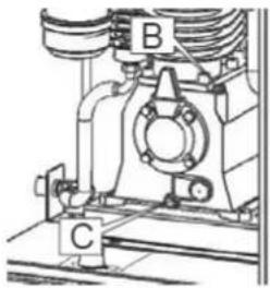
natural_image
Mechanical assembly diagram showing a bearing housing with labeled components A, B, and C (no text or symbols beyond labels)Fig. 11

natural_image
Technical line drawing of a mechanical assembly with labeled components (E and D), no readable text or symbols present.8.2.2. HUILE
natural_image
Line drawing of a mechanical device with labeled components (no text or symbols beyond labels)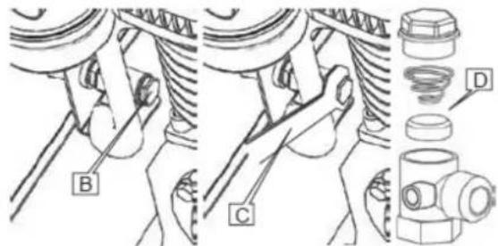
Fig. 12
8.2.4. REMPLACEMENT DE LA CARTOUCHE DU FILTRE À AIR (MODÈLES APZ 600 ET APZ 900)
natural_image
Technical line drawing of a rectangular industrial machine or enclosure with labeled component A (no text or symbols beyond label)
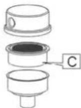
Fig. 13
8.2.5. REMPLACEMENT DE LA COURROIE (MODELES APZ 600 ET APZ 900)
natural_image
Technical line drawing of a mechanical device and a wheel assembly (no text or symbols)9. SCHÉMAS ÉLECTRIQUES
natural_image
Technical line drawing of two industrial equipment units with no visible text or symbolsnatural_image
Technical line drawing of a mechanical assembly with three views: front view, side view, and top view (no text or symbols)- A KOMPRESSZOR HASZNÁLATÁNAK MÓDJA

natural_image
Technical line drawings of industrial equipment including a control box and a cylindrical tank (no text or symbols)Fig. 9
natural_image
Simple line drawing of a cylindrical object next to a coiled cable with mounting flange (no text or symbols)Fig. 10
natural_image
Technical line drawing of a rectangular industrial machine or enclosure with mounting brackets and a label 'A' pointing to the front panel (no readable text or symbols beyond labels)
natural_image
Technical line drawing of a mechanical assembly with labeled components A, B, and C (no text or symbols beyond labels)Fig. 11
natural_image
Technical diagram of a mechanical assembly with labeled components (E, D), no readable text or symbols present.8.2.2. OLAJTÁBLÁZAT
8.2.3. VISSZATARTÓSZELEP CSERE
natural_image
Line drawing of a rectangular industrial machine with labeled components (no text or symbols beyond labels)
Fig. 12
8.2.4. LÉGSZÜRÖBETÉT CSERÉJE MOD. APZ 600 & APZ 900
natural_image
Line drawing of a rectangular industrial machine or enclosure with labeled component A (no text or symbols on the device itself)
natural_image
Technical diagram of a mechanical spring assembly with labeled component B (no text or symbols beyond label)
natural_image
Cross-sectional diagram of a mechanical component with labeled part C (no text or symbols present)Fig. 13
8.2.5. A SZÍJ CSERÉJE (APZ 600 ÉS APZ 900)
natural_image
Technical line drawing of a mechanical device with labeled components A, B, and C (no text or symbols beyond labels)Fig. 14
9. ELEKTROMOS RAJZOK
natural_image
Technical line drawing of two industrial equipment units with no visible text or symbols2. POZITIA COMENZILOR ŞI A COMPONENTELOR DE FUNCTIONARE
6. MODUL DE UTILIZARE A COMPRESORULUI

natural_image
Technical line drawings of industrial equipment including a box and a cylindrical tank (no text or symbols)natural_image
Simple line drawing of a cylindrical container and a coiled cable with a flanged plate, labeled Fig. 10 (no text or symbols on the diagram itself)8.1. CURĂȚAREA COMPRESORULUI
natural_image
Technical line drawing of a rectangular industrial machine or enclosure with mounting brackets and a label 'A' pointing to the front panel (no readable text or symbols beyond labels)
natural_image
Technical line drawing of a mechanical assembly with labeled components A, B, and C (no text or symbols beyond labels)Fig. 11

natural_image
Technical diagram of a mechanical assembly with labeled components (E, D), no readable text or symbols present.8.2.2. TABELUL DE ULEI
natural_image
Technical line drawing of a rectangular industrial machine with labeled components (no text or symbols beyond labels)
Fig. 12
8.2.4. ÎNLOCUIREA CARTUŞULUI FILTRULUI DE AER MOD. APZ 600 ŞI APZ 900
natural_image
Line drawing of a rectangular industrial machine or enclosure with labeled component A (no text or symbols beyond label)
natural_image
Technical diagram of a mechanical spring assembly with labeled component B (no text or symbols beyond label)
natural_image
Cross-sectional diagram of a mechanical component with labeled part C (no text or symbols present)Fig. 13
8.2.5. ÎNLOCUIREA CURELEI (APZ 600 & APZ 900)
natural_image
Technical line drawing of a mechanical device with labeled components A, B, and C (no text or symbols beyond labels)Fig. 14
9. DIAGRAME ELECTRICE
natural_image
Technical line drawing of two industrial equipment units with no visible text or symbols2. UMIESTNENIE PREVÁDZKOVÝCH OVLÁDACÍCH PRVKOV A KOMPONENTOV
5.3. PRIPOJENIE K PNEUMATICKÉMU SYSTÉMU

natural_image
Technical line drawing showing mechanical assembly with arrows indicating motion (no text or symbols)6. AKO POUŽÍVAŤ KOMPRESOR

natural_image
Simple line drawing of a cylindrical object and a coiled cable with mounting flange (no text or symbols)Fig. 10
8.1. ČISTENIE KOMPRESORA
natural_image
Line drawing of a mechanical device with labeled components (no text or symbols beyond labels)
natural_image
Technical line drawing of a mechanical assembly with labeled components A, B, and C (no text or symbols beyond labels)
natural_image
Technical line drawing of a mechanical assembly with labeled components (E, D), no readable text or symbols present.Fig. 11
8.2.2. TABULKA OLEJA
natural_image
Technical line drawings of industrial equipment including a box labeled A and a wheel assembly with labeled components B, C (no text or symbols beyond labels)natural_image
Technical line drawing of two industrial equipment units with internal components and a pump (no text or symbols)2. POLOŽAJ UPRAVLJALNIH ELEMENTOV IN SESTAVNIH DELOV
Spodnja slika predstavlja stroj in glavne dele, iz katerih je sestavljen.

natural_image
Technical line drawing of a mechanical assembly with three views: front view, side view, and top view (no text or symbols)6. KAKO UPORABLJATI KOMPRESOR

natural_image
Simple line drawing of a cylindrical container and a coiled cable with mounting flange (no text or symbols)Fig. 10
8.1. ČIŠČENJE KOMPRESORJA
natural_image
Technical line drawing of a mechanical device with labeled components (no readable text or symbols)
natural_image
Technical line drawing of a mechanical assembly with labeled components A, B, and C (no text or symbols beyond labels)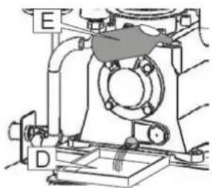
natural_image
Technical diagram of a mechanical assembly with labeled components (E, D), no readable text or symbols present.Fig. 11
8.2.2. STOLNICA ZA OLEJE
Fig. 12
8.2.4. ZAMENJAVA VLOŽKA ZRAČNEGA FILTRA MOD. APZ 600 IN APZ 900
natural_image
Technical line drawings of industrial equipment including a box labeled A and a wheel with labeled components B, C (no text or symbols beyond labels)Fig. 14
9. ELEKTRIČNI DIAGRAMI
V nadaljevanju so predstavljeni legenda in električni sistemi.
natural_image
Technical line drawing of two industrial equipment units with internal components and a separate inset showing a data table (no text or symbols on the devices themselves)2. DARBIBAS VADIBAS IERICU UN SASTAVDALU NOVIETOJUMS
natural_image
Technical line drawing of a mechanical assembly with three views: front view, side view, and top view (no text or symbols)6. KÃ LIETOT KOMPRESORU

natural_image
Simple line drawing of a cylindrical container and a coiled cable with mounting flanges (no text or symbols)Fig. 10
8.1. KOMPRESORA TİRİŞANA
natural_image
Technical line drawing of a mechanical device with labeled component A (no text or symbols beyond labels)
natural_image
Technical line drawing of a mechanical assembly with labeled components A, B, and C (no text or symbols beyond labels)
natural_image
Technical line drawing of a mechanical assembly with labeled components (E, D), no readable text or symbols present.Fig. 11
8.2.2. ELLAS TABULA
Fig. 12
8.2.4. GAISA FILTRA KÄRTRIDŽA NOMAINA MOD. APZ 600 & APZ 900
natural_image
Technical line drawing of industrial equipment including a box labeled A and a wheel with labeled components B, C (no text or symbols beyond labels)Fig. 14
9. ELEKTRISKÃS SHÊMAS
natural_image
Technical line drawing of two industrial machines with control panel and piping (no text or symbols)2. VALDYMO ITAISU IR SUDEDAMUJU DALIU PADÉTIS
3.1. MAŠINOS MATMENYS
3.2. VERSIJA SU ORO REZERVUARU
SKU
KOMPRESORIUS
BANKAS
PISTONAS
CILINDRAS
SLÉGIS
VARIKLIS
ITAMPAS
| 34351 270 34651 270S | ||
| TYPE APZ600-270 APZ900-270S | ||
| litres 270 L 270 L | ||
| CIL 28 28 | ||
| L/min 650 830 | ||
| CFM 23 30 | ||
| m3/h 39 49,8 | ||
| bar 10 10 | ||
| pei 143 143 | ||
| Hp/Cv 5.5 2.5 | ||
| Kw | 4 | 5.5 |
| V/ph 400/3 | 400/3 | |
| RPM | RPM 900 1000 | |
| SVORIS | Kg 248 307 | |
| TRIUKŠMAS | Lbs 546 677 | |
| Džiovykla | dB(A) 68 68 | |
| Dryer -- | ||
| DIMENSIJOS (cm) | A x B x h (cm) 70 x 154 x 158 70 x 154 x 158 |
3.3. ISPĖJAMOSIOS IR INFORMACINĖS ETIKETĖS IR ŽYMOS

natural_image
Technical line drawing of a mechanical assembly with directional arrows indicating motion (no text or symbols)6. KAIP NAUDOTI KOMPRESORIŲ

natural_image
Technical line drawings of industrial equipment components, one showing a cabinet and the other a cylindrical tank (no text or symbols)natural_image
Simple line drawing of a cylindrical container and a coiled cable with mounting flanges (no text or symbols)Fig. 10
8.1. KOMPRESORIAUS VALYMAS
natural_image
Line drawing of a mechanical device with labeled components (no text or symbols beyond labels)
natural_image
Technical line drawing of a mechanical assembly with labeled components A, B, and C (no text or symbols beyond labels)
natural_image
Technical line drawing of a mechanical assembly with labeled components (E, D), no readable text or symbols present.Fig. 11
8.2.2. ALYVOS LENTELÈ
Fig. 12
8.2.4. ORO FILTRO KASETÉS KEITIMAS MOD. APZ 600 IR APZ 900
natural_image
Technical line drawing of a mechanical device with labeled components A, B, and C (no text or symbols beyond labels)Fig. 14
9. ELEKTRINÉS SCHEMOS
Tollau pateikiama elektros sistemu legenda ir schemos.
natural_image
Technical line drawing of two industrial equipment units with internal components and a separate inset showing a data table (no text or symbols on the devices themselves)2. POLOŽAJ UPRAVLJAČKIH KONTROLA I KOMPONENTI
1Spremnik zraka
2Električni motor
3Glava kompresora
6. KAKO KORISTITI KOMPRESOR

natural_image
Technical line drawings of industrial equipment components, one showing a cabinet and the other a cylindrical tank with mounting brackets (no text or symbols)Kompresor bez spremnika zraka mora se podići transportnom paletom ili kamionom odgovarajućeg kapaciteta.
Na isti način se mora podići kompresor sa spremnikom zraka (vidi sl. 9). Težina je prikazana u odjeljku 3.2 Tehničke značajke.
8. ODRŽAVANJE

Prije izvođenja radova održavanja pažljivo pročitajte ovaj odlomak.
natural_image
Simple line drawing of a cylindrical container and a coiled cable with mounting flanges (no text or symbols)Fig. 10
8.1. ČIŠĆENJE KOMPRESORA
Za cjelokupno čišćenje kompresora koristite suhe mlazove zraka i vlažne krpe. Ne koristite otapala, benzine ili vodene mlazove.
8.2. PLANIRANO ODRŽAVANJE
Sljedeća tablica opisuje bitne operacije za dobro održavanje kompresora.
SVAKIH 50 SATI
Provjerite razinu ulja prozimim čepom, mora biti na pola crvene oznake. Ispustite kondenzat pomoću slavine u donjem dijelu spremnika.
SVAKIH 300 SATI
natural_image
Technical line drawing of a mechanical device with labeled component A (no text or symbols beyond labels)
natural_image
Technical line drawing of a mechanical assembly with labeled components A, B, and C (no text or symbols beyond labels)
natural_image
Technical line drawing of a mechanical assembly with labeled components (E, D), no readable text or symbols present.Fig. 11
8.2.2. TABLICA ULJA
Za punjenje spremnika ili potpunu izmjenu ulja kompresora potrebno je koristiti ulje tipa MR ELTE' 46. Sinteličko mazivo rashladno sredstvo za kompresore.
8.2.3. ZAMJENA ZAPORNOG VENTILA
Prije početka zamjene pažljivo pročitajte odjeljak 8.2 PLANIRANO ODRŽAVANJE.
Za zamjenu zapornog ventila potrebno je slijediti ove korake:
| 1 | Isključite iz električne mreže. |
| 2 | Potpuno ispraznite spremnik pomoću slavine za kondenzat. |
| 3 | Ručno odvrnite čep poz. B sl. 14, izvadite uložak i zamijenite ga novim. |
| 4 | Odvrnite šesterokutni navojni vijak poz. B ključem poz. C sl. 12. |
| 5 | Za precizno čišćenje gumene diskete i centriranje, te ako je potrebno za zamjenu s recipročnim položajem D, sl. 12. |
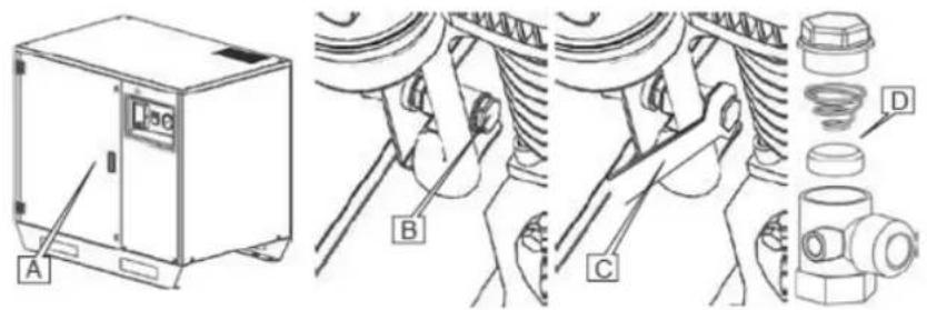
Fig. 12
8.2.4. ZAMJENA ULOŽKA ZRAČNOG FILTRA MOD. APZ 600 I APZ 900
natural_image
Technical line drawings of industrial equipment including a box labeled A and a wheel with labeled components B, C (no text or symbols beyond labels)Fig. 14
9. ELEKTRIČNE SHEMA
natural_image
Technical line drawing of two industrial machines with no visible text or symbols2. UMÍSTĚNÍ OVLÁDACÍCH PRVKŮ A SOUČÁSTÍ
natural_image
Technical line drawing of a mechanical assembly with no visible text or symbols6. JAK POUŽIVAT KOMPRESOR

natural_image
Simple line drawing of a cylindrical container and a coiled cable with mounting flange (no text or symbols)Fig. 10
8.1. ČIŠTĚNÍ KOMPRESORU
natural_image
Line drawing of a mechanical device with labeled components (no text or symbols beyond labels)
natural_image
Technical line drawing of a mechanical assembly with labeled components A, B, and C (no text or symbols beyond labels)
natural_image
Technical line drawing of a mechanical assembly with labeled components (E, D), no readable text or symbols present.Fig. 11
8.2.2. TABULKA OLEJE
natural_image
Technical line drawings of industrial equipment including a box labeled A and a wheel assembly with labeled components B, C (no text or symbols beyond labels)9. ELEKTRICKÁ SCHÉMATA
natural_image
Technical line drawing of two industrial equipment units with no visible text or symbols2. JUHTIMISSEADISTE JA KOMPONENTIDE ASUKOHT
1 Ôhupaak
2 Elektrimootor
3 Peakompressor
4 Hoiuklapp
5 Ölipaak
6 Hädaseiskamine
7 Öhufilter
8 Elektrisüsteem
9 Tundide arvesti
10 Manostaat
11 Kuivati
12 Korpus
13Rihmad
14 Rihmaratas
15 Rihmaratas
16 Elektriline ventilaator
17 Manomeeter
3. ÜLDINE TEAVE
3.1. MASINA MÖÖTMED
3.2. VERSION ON KOOS ÖHUPAAGIGA
SKU
KOMPRESSOR
TANK
PISTON
SILINTER
RŌHU
MOOTOR
PINGED
| 34351-270 34651-270S | ||
| TYPE APZ600-270 APZ900-270S | ||
| litres 270 L 270 L | ||
| CIL 28 2B | ||
| L/min 650 830 | ||
| CFM 23 30 | ||
| m3/h 39 49,8 | ||
| bar 10 10 | ||
| psi 143 143 | ||
| Hp/Cv 5.5 | 7.5 | |
| Kw | 4 | 5.5 |
| V/ph 400/3 | 400/3 | |
| PÖÖRLEMISSAGEDUS | RPM 900 1000 | ||
| KAAL | Kg 248 307 | ||
| MÜRA | Lbs 546 677 | ||
| Kuivati | dB(A) 68 68 | ||
| Dryer -- | |||
| MÖÖTMED (cm) | A x B x h (cm) 70 x 154 x 158 70 x 154 x 158 |
3.3. HOIATUS- JA TEABESILDID NING SILDID

natural_image
Technical line drawing of a mechanical assembly with three views: front view, side view, and top view (no text or symbols)6. KUIDAS KASUTADA KOMPRESSORIT

natural_image
Simple line drawing of a cylindrical container and a coiled cable with mounting flanges (no text or symbols)Fig. 10
8.1. KOMPRESSORI PUHASTAMINE
natural_image
Line drawing of a mechanical device with labeled components (no text or symbols beyond labels)
natural_image
Technical line drawing of a mechanical assembly with labeled components A, B, and C (no text or symbols beyond labels)
natural_image
Technical line drawing of a mechanical assembly with labeled components (E, D), no readable text or symbols present.Fig. 11
8.2.2. ÖLITABEL
Fig. 12
8.2.4. ÖHUFILTRI PADRUNITE VAHETAMINE MOD. APZ 600 & APZ 900
natural_image
Technical line drawings of industrial equipment including a box labeled A and a wheel with labeled components B, C (no text or symbols beyond labels)Fig. 14
9. ELEKTRISKEEMID
natural_image
Technical line drawing of two industrial equipment units with no visible text or symbols2. POSIZIONE DEI COMANDI E DEI COMPONENTI OPERATIVI
6. COME UTILIZZARE IL COMPRESSORE

natural_image
Technical line drawings of industrial equipment including a control box and a cylindrical tank (no text or symbols)natural_image
Simple line drawing of a cylindrical container and a coiled cable with a flanged mounting bracket (no text or symbols)Fig. 10
8.1. PULIZIA DEL COMPRESSORE
natural_image
Line drawing of a mechanical device with labeled components (no text or symbols beyond labels)
natural_image
Technical line drawing of a mechanical assembly with labeled components A, B, and C (no text or symbols beyond labels)Fig. 11

natural_image
Technical diagram of a mechanical assembly with labeled components (E, D), no readable text or symbols present.8.2.2. TABELLA OLIO
natural_image
Technical line drawing of a rectangular industrial machine with labeled components (no text or symbols beyond labels)
Fig. 12
8.2.4. SOSTITUZIONE DELLA CARTUCCIA DEL FILTRO DELL'ARIA MOD. APZ 600 & APZ 900
natural_image
Line drawing of a rectangular industrial machine or enclosure with labeled component A (no text or symbols beyond label)
natural_image
Technical line drawing of a mechanical spring assembly with labeled component B (no text or symbols beyond label)
natural_image
Cross-sectional diagram of a mechanical component with labeled part C (no text or symbols present)Fig. 13
natural_image
Technical line drawings of industrial equipment including a box labeled A and a wheel assembly with labeled components (B, C), no readable text or symbols present.9. SCHEMI ELETTRICI
natural_image
Technical line drawing of two industrial equipment units with no visible text or symbolsnatural_image
Technical line drawing of a mechanical assembly with three views: front view, side view, and top view (no text or symbols)natural_image
Technical line drawings of industrial equipment including a control box and a cylindrical tank (no text or symbols)natural_image
Simple line drawing of a cylindrical container and a coiled cable with a mounting bracket (no text or symbols)Fig. 10
8.1. LIMPEZA DO COMPRESSOR
natural_image
Line drawing of a mechanical device with labeled components (no text or symbols beyond labels)
natural_image
Technical line drawing of a mechanical assembly with labeled components A, B, and C (no text or symbols beyond labels)Fig. 11

natural_image
Technical diagram of a mechanical assembly with labeled components (E, D), no readable text or symbols present.8.2.2. TABELA DE ÓLEO
natural_image
Technical line drawing of a rectangular industrial machine with labeled components (no text or symbols beyond labels)
Fig. 12
8.2.4. SUBSTITUIÇÃO DO CARTUCHO DO FILTRO DE AR MOD. APZ 600 & APZ 900
natural_image
Line drawing of a rectangular industrial machine or enclosure with labeled component A (no text or symbols beyond label)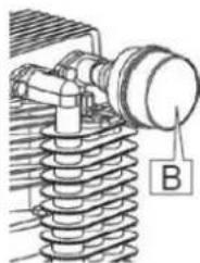
natural_image
Technical line drawing of a mechanical spring assembly with labeled component B (no text or symbols beyond label)
natural_image
Cross-sectional diagram of a mechanical component with labeled part C (no text or symbols beyond label)Fig. 13
8.2.5. SUBSTITUIÇÃO DA CORREIA (APZ 600 & APZ 900)
natural_image
Technical line drawing of two industrial equipment units with no visible text or symbolsnatural_image
Technical line drawing of a mechanical assembly with directional arrows indicating motion (no text or symbols)natural_image
Technical line drawings of industrial equipment, one showing a cabinet and the other a cylindrical tank with mounting brackets (no text or symbols)natural_image
Technical line drawing of a cylindrical object and a looped mechanical component (no text or symbols)8.1. LIMPIEZA DEL COMPRESOR
natural_image
Line drawing of a mechanical device with labeled component A (no text or symbols beyond labels)
natural_image
Technical line drawing of a mechanical assembly with labeled components A, B, and C (no text or symbols beyond labels)
natural_image
Technical line drawing of a mechanical assembly with labeled components (no readable text or symbols)Fig. 11
natural_image
Technical line drawing of a mechanical device with labeled components (no readable text or symbols)
Fig. 12
natural_image
Line drawing of a white industrial machine with labeled component A (no text or symbols beyond label)
natural_image
Technical illustration of a mechanical spring assembly with labeled component B (no text or symbols beyond label)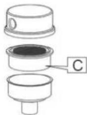
natural_image
Diagram of a mechanical component with three views, labeled C (no text or symbols present)Fig. 13
natural_image
Technical line drawing of a mechanical device and a wheel assembly (no text or symbols)9. ESQUEMAS ELÉCTRICOS
natural_image
Technical line drawing of two industrial equipment units with no visible text or symbolsnatural_image
Technical line drawing of a mechanical assembly with three views: front view, side view, and top view (no text or symbols)natural_image
Technical line drawings of industrial equipment components, one showing a cabinet and the other a cylindrical tank (no text or symbols)natural_image
Technical line drawing of a cylindrical object and a coiled cable with mounting bracket, labeled Fig. 10 (no text or symbols on the diagram itself)natural_image
Line drawing of a rectangular industrial machine with labeled components (no text or symbols beyond labels)
natural_image
Technical diagram of a mechanical assembly with labeled components A, B, and C (no readable text or symbols beyond labels)Fig. 11
natural_image
Technical diagram of a mechanical assembly with labeled components (E, D), no readable text or symbols present.8.2.2. ТАБЛИЦЯ ЗАМІНИ ОЛИВИ
natural_image
Line drawing of a rectangular industrial machine with labeled components (no text or symbols beyond labels)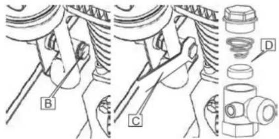
Fig. 12
8.2.4. ЗАМИНА КАРТРИДЖА ПОВІТРЯНОГО ФІЛЬТРА МОД. АРЗ 600 ТА АРЗ 900
Fig. 13
natural_image
Technical line drawing of a mechanical device with labeled components A, B, and C, showing internal components and assembly (no text or symbols beyond labels)9. ЕЛЕКТРИЧНІ СХЕМИ
natural_image
Technical line drawing of two industrial equipment units with internal components and a separate inset showing a data table (no text or symbols on the devices themselves)2. KÄYTTÖSÄÄTIMIEN JA KOMPONENTTIEN SIJAINTI
natural_image
Technical line drawing of a mechanical assembly with three views: front view, side view, and top view (no text or symbols)6. MITEN KOMPRESSORIA KÄYTETÄÄN

natural_image
Simple line drawing of a cylindrical container and a coiled cable with mounting flanges (no text or symbols)Fig. 10
8.1. KOMPRESSORIN PUHDISTUS
natural_image
Line drawing of a mechanical device with labeled components (no text or symbols beyond labels)
natural_image
Mechanical assembly diagram showing a bearing housing with labeled components A, B, and C (no text or symbols beyond labels)
natural_image
Technical line drawing of a mechanical assembly with labeled components (E, D), no readable text or symbols present.Fig. 11
8.2.2. ÖLJYTAULUKKO
Fig. 12
8.2.4. ILMANSUODATINPATRUUNAN VAIHTO MOD. APZ 600 & APZ 900
Fig. 13
8.2.5. HIHNAN VAIHTO (APZ 600 JA APZ 900)
natural_image
Technical line drawings of industrial equipment including a box labeled A and a wheel with labeled components B, C (no text or symbols beyond labels)Fig. 14
9. SÄHKÖKAAVIOT
natural_image
Technical line drawing of two industrial equipment units with no visible text or symbols2. PLASSERING AV BETJENINGSKONTROLLER OG KOMPONENTER
1 Lufttank
2 Elektrisk motor
3 Hovedkompressor
4 Holdeventil
5 Olietank
6 Nødstopp
7 Luftfilter
8 Elektrisk system
9 Timeteller
10 Manostat
11 Tørketrommel
12 Foringsrør
13 Stropper
14 Remskive
15 Remskive
16 Elektrisk vifte
17 Manometer
3. GENERELL INFORMASJON
3.1. MASKINDIMENSJONER

3.2. VERSJON MED LUFTTANK
SKU
KOMPRESSOR
TANK
PISTON
CYLINDER
TRYKK
| MOTOR | 34351-270 34651-270S | ||
| TYPE APZ60 D-270 APZ900-270S | |||
| litres 270 L 270 L | |||
| CIL 2B 2B | |||
| L/min 650 B30 | |||
| CFM 23 30 | |||
| m3/h 39 49.8 | |||
| bar 10 10 | |||
| psi 143 143 | |||
| Hp/Cv 5.5 | 7.5 | ||
| Kw | 4 | 5.5 | |
| SPENNING | V/ph 400/3 | 400/3 | |
| RPM | RPM | 900 | 1000 |
| VEKT | Kg | 248 307 | |
| ST∅Y | Lbs 546 677 | ||
| Tørketrommel | dB(A) | 68 68 | |
| Dryer - | - | ||
| DIMENSJONER (cm) | A x B x h (cm) | 70 x 154 x 158 | 70 x 154 x 158 |
3.3. ADVARSELS- OG INFORMASJONSETIKETTER OG -MERKER

natural_image
Technical line drawing of a mechanical assembly with directional arrows indicating motion (no text or symbols)6. HVORDAN BRUKE KOMPRESSOREN

natural_image
Technical line drawings of industrial equipment including a box and a cylindrical tank with mounting brackets (no text or symbols)Kompressoren uten lufttank må løftes med en transpall eller en lastebil med passende kapasitet.
natural_image
Simple line drawing of a cylindrical object and a coiled cable with mounting flange (no text or symbols)Fig. 10
8.1. RENGJ∅RING AV KOMPRESSOREN
natural_image
Line drawing of a white industrial machine casing with labeled component A (no text or symbols beyond labels)
natural_image
Technical line drawing of a mechanical assembly with labeled components A, B, and C (no text or symbols beyond labels)Fig. 11

natural_image
Technical diagram of a mechanical assembly with labeled components (E, D), no readable text or symbols present.8.2.2. OLJETABELL
8.2.3. UTSKIFTING AV HOLDEVENTIL
Les nøye gjennom avsnitt 8.2 PLANLAGT VEDLIKEHOLD før du starter utskiftingen.
natural_image
Line drawing of a rectangular industrial machine with labeled components (no text or symbols beyond labels)
Fig. 12
8.2.4. UTSKIFTING AV LUFTFILTERPATRON MOD. APZ 600 & APZ 900
natural_image
Technical line drawing of a rectangular industrial machine with labeled component A (no text or symbols beyond label)
natural_image
Technical illustration of a mechanical spring assembly with labeled component B (no text or symbols beyond label)
natural_image
Cross-sectional diagram of a mechanical component with labeled part C (no text or symbols beyond label)Fig. 13
8.2.5. UTSKIFTING AV REIM (APZ 600 & APZ 900)
natural_image
Technical line drawing of a mechanical device with labeled components A, B, and C, showing internal components and assembly (no text or symbols beyond labels)9. ELEKTRISKE DIAGRAMMER
10. FEILS∅KING
| PROBLEM |
| Kompressoren starter ikke. |
| ÅRSAK |
| - den elektriske forsyningen mangler,- nettspenningen er ikke den som er angitt på platen,- termisk beskyttelse av motoren er på,- kompressoren er under trykk,- trykkbryteren er defekt. |
| L∅SNING |
| - Kontroller tilkoblingen til det elektriske systemet,- reaktiver motorens termiske beskyttelse (av en spesialisert tekniker),- tam tanken,- kontroller den elektromekaniske effektiviteten til trykkbryteren. |
natural_image
Technical line drawing of two industrial equipment units with control panels and a cylindrical housing (no text or symbols)2. ПОЗИЦИЈА НА РАБОТНИТЕ КОНТРОЛИ И КОМПОНЕНТИ
5.3. ПОВРЗУВАЊЕ СО ПНЕВМАТСКИОТ СИСТЕМ

natural_image
Technical line drawing of a mechanical assembly with three views: front view, side view, and top view (no text or symbols)natural_image
Technical line drawings of industrial equipment components, one showing a cabinet and the other a cylindrical tank (no text or symbols)natural_image
Technical line drawing of a cylindrical object and a looped mechanical component (no text or symbols)8.1. ЧИСТЕЊЕ НА КОМПРЕСОРОТ
natural_image
Line drawing of a mechanical device with labeled component A (no text or symbols beyond labels)
natural_image
Technical line drawing of a mechanical assembly with labeled components A, B, and C (no text or symbols beyond labels)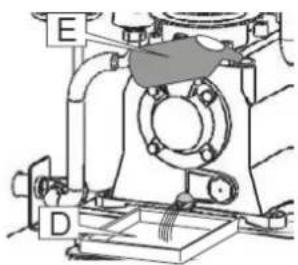
natural_image
Technical diagram of a mechanical assembly with labeled components (E, D), no readable text or symbols present.Fig. 11
8.2.2. ТАБЕЛА ЗА МАСЛО
natural_image
Line drawing of a rectangular industrial machine with labeled components (no text or symbols beyond labels)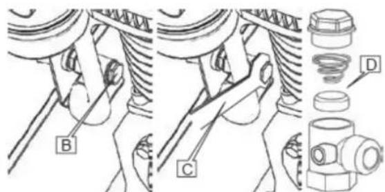
Fig. 12
natural_image
Line drawing of a rectangular industrial machine or enclosure with labeled component A (no text or symbols beyond label)
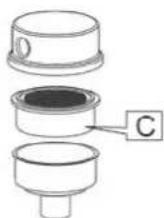
Fig. 13
8.2.5. 3AMEHA HA PEWEH (APZ 600 & APZ 900)
natural_image
Technical line drawing of a mechanical device with labeled components A, B, and C, showing internal components and motion lines (no text or symbols beyond labels)9. ЕЛЕКТРИЧНИ ДИЈАГРАМИ
natural_image
Technical line drawing of two industrial equipment units with no visible text or symbols2. POZICIONI I KONTROLLIT DHE I KOMPONENTÈVE OPERUES
1Rezervuar ajri
2Motor elektrik
3Kompresor koke
4Valvula mbajtëse
natural_image
Technical line drawing of a mechanical assembly with three views: front view, side view, and top view (no text or symbols)6. SI TË PËRDORNI KOMPRESORIN

natural_image
Technical line drawings of industrial equipment components, one showing a cabinet and the other a cylindrical tank (no text or symbols)natural_image
Technical line drawing of a cylindrical object and a coiled cable with mounting bracket, labeled Fig. 10 (no text or symbols on the diagram itself)8.1. PASTRIMI I KOMPRESORIT
natural_image
Line drawing of a mechanical device with labeled components (no text or symbols beyond labels)
natural_image
Technical line drawing of a mechanical assembly with labeled components A, B, and C (no text or symbols beyond labels)Fig. 11

natural_image
Technical line drawing of a mechanical assembly with labeled components (no readable text or symbols)8.2.2. TABELA E VAJIT
natural_image
Line drawing of a mechanical device with labeled components (no text or symbols beyond labels)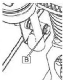
natural_image
Mechanical diagram showing a hand holding a tool with labeled point B (no text or symbols present)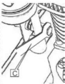
natural_image
Mechanical diagram showing a hand operating a car wheel (no text or symbols visible)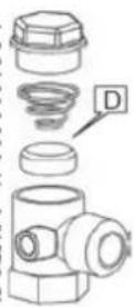
Fig. 12
8.2.4. MOD ZÉVENDÉSUES I FILTRIT TË AJRIT APZ 600 & APZ 900
Fig 13
8.2.5. ZËVENDËSIMI I RRIPIT (APZ 600 & APZ 900)
natural_image
Technical line drawings of industrial equipment including a box labeled A and a wheel with pulleys labeled B, C, and I, shown without any text or symbols.9. DIAGRAMA ELEKTRIKE
natural_image
Technical line drawing of two industrial equipment units with no visible text or symbols1Резервоар за ваздух
2Електрични мотор
ЗГлава компресора
4Запорни вентил
5Резервоар за уље
natural_image
Technical line drawing of a mechanical assembly with directional arrows indicating motion (no text or symbols)natural_image
Technical line drawings of industrial equipment components, one showing a cabinet and the other a cylindrical tank (no text or symbols)natural_image
Technical line drawing of a cylindrical object and a looped mechanical bracket (no text or symbols)8.1. ЧИШТЕЊЕ КОМПРЕСОРА
natural_image
Technical line drawing of a mechanical device with labeled components (no readable text or symbols)
natural_image
Technical line drawing of a mechanical assembly with labeled components A, B, and C (no text or symbols beyond labels)Fig. 11
natural_image
Technical line drawing of a mechanical assembly with labeled components (no readable text or symbols)8.2.2. ТАБЕЛА УЛЬА
natural_image
Line drawing of a rectangular industrial machine with labeled components (no text or symbols beyond labels)
Fig. 12
natural_image
Technical line drawing of a mechanical device with labeled component A (no text or symbols beyond label)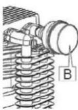
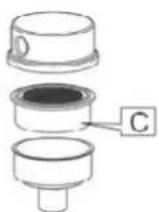
Fig. 13
natural_image
Technical line drawings of industrial equipment including a box labeled A and a wheel with a pulley (no text or symbols present)natural_image
Technical line drawing of two industrial machines with control panel and piping (no text or symbols)2. PLACERING AV MANÖVERORGAN OCH KOMPONENTER
natural_image
Technical line drawing of a mechanical assembly with three views: front view, side view, and top view (no text or symbols)- HUR MAN ANVÄNDER KOMPRESSORN

natural_image
Technical line drawings of industrial equipment including a box and cylindrical tank (no text or symbols)Fig. 9
natural_image
Technical line drawing of a cylindrical component connected to a coiled cable with mounting flange (no text or symbols)Fig. 10
8.1. RENGÖRING AV KOMPRESSORN
natural_image
Technical line drawing of a rectangular industrial machine or enclosure with mounting brackets and a label 'A' pointing to the front panel (no readable text or symbols beyond labels)
natural_image
Technical line drawing of a mechanical assembly with labeled components A, B, and C (no text or symbols beyond labels)Fig. 11

natural_image
Technical diagram of a mechanical assembly with labeled components (E, D), no readable text or symbols present.8.2.2. OLJETABELL
natural_image
Line drawing of a mechanical device with labeled components (no text or symbols beyond labels)
Fig. 12
8.2.4. BYTE AV LUFTFILTERPATRON MOD. APZ 600 & APZ 900
natural_image
Line drawing of a rectangular industrial machine with labeled component A (no text or symbols beyond label)
natural_image
Technical line drawing of a mechanical spring assembly with labeled component B (no text or symbols beyond label)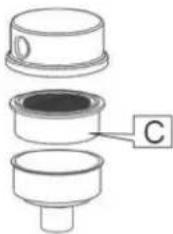
natural_image
Cross-sectional diagram of a mechanical component with labeled part C (no text or symbols beyond label)Fig. 13
8.2.5. BYTE AV REM (APZ 600 & APZ 900)
natural_image
Technical line drawing of industrial equipment including a box labeled A, a wheel labeled B, and a mechanical component labeled C (no text or symbols present)9. ELEKTRISKA DIAGRAM
natural_image
Technical line drawing of two industrial equipment units with no visible text or symbols2. PLACERING AF BETJENINGSELEMENTER OG KOMPONENTER
1 Luftbeholder
2 Elektrisk motor
3 Hovedkompressor
4 Fastholdelsesventil
5 Olietank
6 Nødstop
7 Luftfilter
8 Elektrisk system
9 Timetæller
10 Manostat
11 Tørretumbler
12 Indkapsling
13 Stropper
14 Remskive
15 Remskive
16 Elektrisk ventilator
17 Manometer
3. GENERELLE OPLYSNINGER
3.1. MASKINENS DIMENSIONER

3.2. VERSION MED LUFTTANK
SKU
KOMPRESSOR
TANK
PISTON
CYLINDER
TRYK
| 34351-270 34651-270S | |||
| MOTOR | TYPE APZ600-270 APZ900-270S | ||
| litres 270 L 270 L | |||
| CIL 28 2B | |||
| L/min 650 830 | |||
| CFM 23 30 | |||
| m3/h 39 49,8 | |||
| bar 10 10 | |||
| psi 143 143 | |||
| Hp/Cv 5.5 7.5 | |||
| Kw | 4 | 5.5 | |
| SP/ENDING | V/ph 400/3 | 400/3 | |
| RPM | RPM | 900 | 1000 |
| V/EGT | Kg | 248 307 | |
| ST∅J | Lbs 546 677 | ||
| Tørretumbler | dB(A) | 68 68 | |
| Dryer - | |||
| DIMENSIONER (cm) | A x B x h (cm) | 70 x 154 x 158 | 70 x 154 x 158 |
3.3. ADVARSELS- OG INFORMATIONSMÄERKER OG ETIKETTER

1 Generelle adversier
2 Fare for det elektriske system
3 Motorens rotationsretning
4. SIKKERHEDSFORANSTALTNINGER

6. HVORDAN MAN BRUGER KOMPRESSOREN

natural_image
Simple line drawing of a cylindrical container and a coiled cable with a mounting bracket (no text or symbols)Fig. 10
8.1. RENG∅RING AF KOMPRESSOREN
natural_image
Line drawing of a mechanical device with labeled components (no text or symbols beyond labels)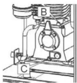
natural_image
Technical diagram of a mechanical assembly with labeled components A, B, and C (no readable text or symbols beyond labels)Fig. 11
natural_image
Technical diagram of a mechanical assembly with labeled components (E, D), no readable text or symbols present.8.2.2. OLIETABEL
8.2.3. UDSKIFTNING AF HOLDEVENTIL
natural_image
Line drawing of a rectangular industrial machine with labeled components (no text or symbols beyond labels)
Fig. 12
8.2.4. UDSKIFTNING AF LUFTFILTERPATRON MOD. APZ 600 & APZ 900
natural_image
Line drawing of a mechanical device with labeled component A (no text or symbols beyond label)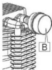
natural_image
Technical illustration of a mechanical spring assembly with labeled component B (no text or symbols beyond label)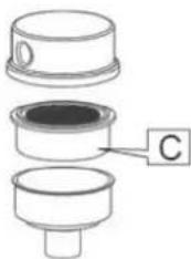
natural_image
Cross-sectional diagram of a mechanical component with labeled part C (no text or symbols beyond label)Fig. 13
8.2.5. UDSKIFTNING AF REM (APZ 600 & APZ 900)
natural_image
Technical line drawings of industrial equipment including a box labeled A and a wheel with labeled components B, C (no text or symbols beyond labels)Fig. 14
9. ELEKTRISKE DIAGRAMMER
natural_image
Technical line drawing of two industrial equipment units with no visible text or symbols2. STADSETNING STJÓRNBÚNADA OG ÍHLUTNA
1Lofttankur
2Rafmòtor
3Höfuðpjöppu
4Haltuloki
50liutankur
6Neyðarstöðvun
7Loftsia
8Rafkerfi
9Tímamællir
10Manostat
11Purrkari
12Hlf
13Ólar
14Talia
15Talla
16 áraRafmagnsvifta
17 áraPrýstimælir
3. ALMENNAR UPPLÝSINGAR
3.1. VÉLARSTÆDI

3.2. ÚTGÁFA MED LOFTGEYMI
Vörunúmer
PJAPPA
TANK
STIMPLA
STRÖKKUR
PRYSTINGUR
MÓTOR
SPENNA
| 34351-270 34651-270S | ||
| TYPE APZ600 270 APZ900 270S | ||
| litres 270 L 270 L | ||
| CIL 2B 2B | ||
| L/min 650 830 | ||
| CFM 23 30 | ||
| m3/h 39 49,8 | ||
| bar 10 10 | ||
| psi 143 143 | ||
| Hp/Cv 5.5 7.5 | ||
| Kw | 4 | 5.5 |
| V/ph 400/3 | 400/3 | |
| RPM | RPM 900 1000 | |
| PYNGD | Kg 248 307 | |
| HÄVİDI | Lbs 546 677 | |
| Burrkari | dB(A) 68 68 | |
| Dryer -- | ||
| MÄL (cm) | A x B x h (cm) 70 x 154 x 158 70 x 154 x 156 |
3.3. VIDVARANIR OG UPPLÝSINGAMERKI OG MERKIMIDAR

natural_image
Technical line drawing of a mechanical assembly with three views: front view, side view, and top view (no text or symbols)6. HVERNIG Á AD NOTA PJÁPPUNA

natural_image
Simple line drawing of a cylindrical container and a coiled cable with a bracket, labeled Fig. 10 (no text or symbols on the diagram itself)8.1. PRIF Á PJÓTTU
natural_image
Line drawing of a white industrial machine casing with labeled component A (no text or symbols beyond labels)
natural_image
Mechanical assembly diagram showing a bearing housing with labeled components (B, C), no readable text or symbols present.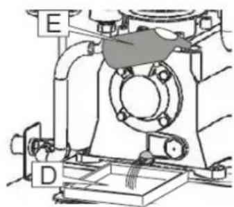
Fig. 11
8.2.2. OLÍUTAFLA
natural_image
Technical line drawings of industrial equipment including a box labeled A and a wheel with labeled components (B, C), no readable text or symbols beyond labels.9. RAFMAGNSKÝRINGAR
- BILANALEIT
natural_image
Technical line drawing of two industrial equipment units with no visible text or symbols2. POSITIUN VUN DE BEDRIEFSKONTROLLEN A KOMPONENTEN
1Lofttank
2Elektromotor
3Kappkompressor
4Haltventil
5Uelegtank
6Noutstopp
7Loftfilter
8Elektrescht System
9Stonnezieler
10Manostat
11 Trockner
12Gehäuse
13Riemen
14Riemscheiw
15Riemscheiw
16Elektresche Ventilator
17 JoerManometer
3. ALLGEMENG INFORMATIONUNEN
3.1. MASCHINNENDIMENSIOUNEN

3.2. VERSION MAT LUFTTANK
Artikelnummer
KOMPRESSOR
TANK
KOLB
Zylinder
Drock
MOTOR
SPANNUNG
| 34351-270 34651-270S | ||
| TYPE APZ600 270 APZ900 270S | ||
| litres 270 L 270 L | ||
| CIL 28 28 | ||
| L/min 650 830 | ||
| CFM 23 30 | ||
| m3/h 39 49,8 | ||
| bar 10 10 | ||
| psi 143 143 | ||
| Hp/Cv 5.5 7.5 | ||
| Kw | 4 | 5.5 |
| V/ph 400/3 | 400/3 | |
| RPM | RPM 900 1000 | |
| GEWICHT | Kg 248 307 | |
| Kaméidi | Lbs 546 677 | |
| Trockner | dB(A) 68 68 | |
| Dryer -- | ||
| DIMENSIOUNEN (cm) | A x B x h (cm) 70 x 154 x 158 70 x 154 x 158 |
3.3. WARNUNGS- AN INFORMATIOUNS-ETIKETTEN AN ETIKETTEN

1 Allgemeng Warnungen
natural_image
Technical line drawing of a mechanical assembly with three views: front view, side view, and top view (no text or symbols)6. WÉI BENOTZT EE DE KOMPRESSOR

natural_image
Simple line drawing of a cylindrical container and a coiled cable with mounting flange (no text or symbols)Fig. 10
natural_image
Technical line drawing of a rectangular industrial machine or enclosure with labeled components (no text or symbols beyond labels)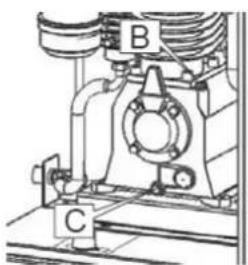
natural_image
Technical line drawing of a mechanical assembly with labeled components A, B, and C (no text or symbols beyond labels)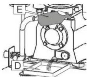
Fig. 11
8.2.2. Uelegtabell
Fir den Tank opzefällen oder den Ueleg vum Kompressor komplett ze wiesselen, ass et néideg den Uelegtyp MR ELTE' 46 ze benotzen. Synthetescht Schmiemettel a Kältemettel fir Kompressoren.
8.2.3. ERSATZ VUM HALTVENTIL
Fig. 12
8.2.4. AUSTAUS VUN DER LUCHTFILTERPATROUN MOD. APZ 600 & APZ 900
Fig. 13
natural_image
Technical line drawings of industrial equipment including a box labeled A and a wheel with labeled components B, C (no text or symbols beyond labels)Fig. 14
natural_image
Technical line drawing of two industrial equipment units with no visible text or symbolsnatural_image
Technical line drawing of a mechanical assembly with three views: front view, side view, and top view (no text or symbols)6. ЯК ВЫКАРЫСТОУВАЦЬ КАМПРЭСАР

natural_image
Technical line drawing of a cylindrical component and a looped mechanical bracket (no text or symbols)8.1. ЧЫСТКА КАМПРЭСАРА
natural_image
Technical line drawing of a mechanical device with labeled component A (no text or symbols beyond labels)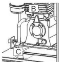
natural_image
Mechanical assembly diagram showing a bearing housing with labeled components A, B, and C (no text or symbols beyond labels)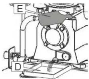
natural_image
Technical line drawing of a mechanical assembly with labeled components (E, D), no readable text or symbols present.Fig. 11
8.2.2. ТАБЛІЦА АЛЕЙ
Fig. 12
8.2.4. ЗАМЕНА КАРТРЫДЖА ПАВЕТРАНАГА ФІЛЬТРА МОД. АРЗ 600 I АРЗ 900
Fig. 13
8.2.5. ЗАМЕНА РАМЕНЯ (APZ 600 & APZ 900)
natural_image
Technical line drawings of industrial equipment including a box labeled A, a wheel with labeled components B, and a cart (no text or symbols present)Fig. 14
- ПОШУК I ВЫРАШЭННЕ НЕПАЛАДАК
natural_image
Technical line drawing of two industrial machines with no visible text or symbols2. РАЗПОЛОЖЕНИЕ НА УПРАВЛЯВАЩИТЕ ЕЛЕМЕНТИ И КОМПОНЕНТИ
natural_image
Technical line drawing showing mechanical assembly and door panel assembly (no text or symbols)natural_image
Simple line drawing of a cylindrical container and a coiled cable with mounting flange (no text or symbols)Fig. 10
8.1. ПОЧИСТВАНЕ НА КОМПРЕСОРА
natural_image
Line drawing of a mechanical device with labeled components (no text or symbols beyond labels)
natural_image
Technical line drawing of a mechanical assembly with labeled components A, B, and C (no text or symbols beyond labels)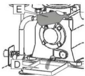
natural_image
Technical line drawing of a mechanical assembly with labeled parts E and D (no text or symbols beyond labels)Fig. 11
8.2.2. ТАБЛИЦА С МАСЛА
Fig. 12
8.2.4. ЗАМЯНА НА КАРТУШАТА НА ВЪЗДУШНИЯ ФИЛТЪР МОД. АРZ 600 & АРZ 900
natural_image
Technical line drawing of a mechanical device with labeled components A, B, and C (no text or symbols beyond labels)Fig. 14
9. ЕЛЕКТРИЧЕСКИ СХЕМИ

- ОТСТРАНЯВАНЕ НА НЕИЗПРАВНОСТИ
natural_image
Technical line drawing of two industrial equipment units with no visible text or symbolsnatural_image
Technical line drawing of a mechanical assembly with three views: front view, side view, and top view (no text or symbols)natural_image
Technical line drawings of industrial equipment, one showing a cabinet and two views of a cylindrical tank (no text or symbols)natural_image
Simple line drawing of a cylindrical container and a coiled cable with mounting flange (no text or symbols)Fig. 10
natural_image
Line drawing of a rectangular industrial machine or enclosure with labeled component A (no text or symbols beyond labels)
natural_image
Technical line drawing of a mechanical assembly with labeled components A, B, and C (no text or symbols beyond labels)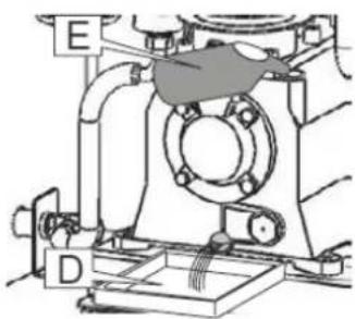
natural_image
Mechanical assembly diagram showing a valve and housing component (no text or labels)Fig. 11
Fig. 12
natural_image
Technical line drawings of industrial equipment including a box labeled A and a wheel with labeled components B, C (no text or symbols beyond labels)Fig. 14
9. НЛЕКТРИКА ДІАГРАММАТА

natural_image
Technical line drawing of two industrial equipment units with no visible text or symbols3.2. HAVA DEPOSULU VERSIYON
SKU
KOMPRESÖR
TANK
PISTON
SILINDIR
BASINÇ
MOTOR
VOLT
| 34351-270 34651-270S | ||
| TYPE APZ600-270 APZ900-270S | ||
| litres 270 L 270 L | ||
| CIL 2B 2B | ||
| L/min 650 830 | ||
| CFM 23 30 | ||
| m3/h 39 49,8 | ||
| bar 10 10 | ||
| psi 143 143 | ||
| Hp/Cv 5.5 2.5 | ||
| Kw | 4 | 5.5 |
| V/ph 400/3 | 400/3 | |
| DÖNÜŞ SAYISI | RPM 900 1000 | |
| AĞIRLIK | Kg 248 307 | |
| GÜRÜLTÜ | Lbs 546 677 | |
| Kurutucu | dB(A) 68 68 | |
| Dryer -- | ||
| BOYUTLAR (cm) | A x B x h (cm) 70 x 154 x 158 70 x 154 x 158 |
3.3. UYARI VE BİLGİ ETİKETLERİ VE ETİKETLER
natural_image
Technical line drawing showing mechanical assembly and door panel assembly (no text or symbols)6. KOMPRESÖRÜN KULLANIMI

natural_image
Technical line drawings of industrial equipment including a control box and a cylindrical tank (no text or symbols)Fig. 9
natural_image
Simple line drawing of a cylindrical container and a coiled cable with mounting flanges (no text or symbols)Fig. 10
8.1. KOMPRESÖR TEMİZLİĞI
natural_image
Technical line drawing of a mechanical device with labeled component A (no text or symbols beyond labels)
natural_image
Technical line drawing of a mechanical assembly with labeled components A, B, and C (no text or symbols beyond labels)
natural_image
Technical line drawing of a mechanical assembly with labeled components (E, D), no readable text or symbols present.Fig. 11
8.2.2. YAĞ TABLOSU
Fig. 12
8.2.4. HAVA FILTRESI KARTUŞUNUN DEĞİŞTİRİLMESİ MOD. APZ 600 & APZ 900
natural_image
Technical line drawing of a mechanical device with labeled components A, B, and C (no text or symbols beyond labels)Fig. 14
- SORUN GİDERME
natural_image
Technical line drawing of two industrial equipment units with no visible text or symbols2. SUÍOMH NA RIALÚCHÁN AGUS NA gCOMHPHÁIRTEANNA OIBRÍOCHTA
1Umar aeir
2Mötar leictreach
16lucht leanúna leictreach
17Manóiméadar
3. EOLAS GINEARÁLTA
3.1. TOISÍ AN MHEASÁIN

3.2. LEAGAN LE UMAR AEIR
SKU
COMHRÉITHEOIR
UMAR
PISTON
SORCÓIR
BRÚ
MÓTAR
VOLTAS
| 34351-270 34651-270S | ||
| TYPE APZ600 270 APZ900 270S | ||
| litres 270 L 270 L | ||
| CIL 28 28 | ||
| L/min 650 830 | ||
| CFM 23 30 | ||
| m3/h 39 49,8 | ||
| bar 10 10 | ||
| psi 143 143 | ||
| Hp/Cv 5.5 | 7.5 | |
| Kw | 4 | 5.5 |
| V/ph 400/3 | 400/3 | |
| RPM | RPM 900 1000 | ||
| MEÁCHAN | Kg 248 307 | ||
| TORANN | Lbs 546 677 | ||
| Triomadóir | dB(A) 68 68 | ||
| Dryer -- | |||
| TOISÍ (cm) | A x B x h (cm) 70 x 154 x 158 70 x 154 x 158 |
1 Rabhaidh ghinearālta
2Guais an chôrais leictrigh
3Treo rothlaithe an mhôtair
4. RÉAMHCHÚRAM SÁBHÁILTEACHTA

4.1. RIALACHA OIBRE OIBREOIRI

natural_image
Technical line drawing of a mechanical assembly with no visible text or symbols6. CONAS AN COMHBHRUITHEOIR A ÚSÄID

natural_image
Technical line drawings of industrial equipment including a control box and a cylindrical tank (no text or symbols)natural_image
Simple line drawing of a cylindrical object next to a coiled cable with mounting flange (no text or symbols)Fig. 10
8.1. GLANADH AN CHOMHBHREATAI
8.2. COINNÍOLL PLEANÁILTE
natural_image
Technical line drawing of a mechanical device with labeled components (no text or symbols beyond labels)
natural_image
Technical line drawing of a mechanical assembly with labeled components A, B, and C (no text or symbols beyond labels)
natural_image
Technical line drawing of a mechanical assembly with labeled components (E and D), no readable text or symbols present.Fig. 11
8.2.2. TÁBLA OLA
8.2.3. ATHSHOLÁTHAR AN CHOMHLA CHOINNEÁLA
Fig. 12
8.2.4. ATHSHOLÁTHAR DÁRTHAIS SCAGAIRE AEIR MOD. APZ 600 & APZ 900
natural_image
Technical line drawings of industrial equipment including a box labeled A and a wheel with labeled components B, C (no text or symbols beyond labels)Fig. 14
9. LÉARÁIDÍ LEICTREACHA

- WARRANTY
- SAFETY SYMBOLS
- INTRODUCTION
- MACHINE DOCUMENTATION
- APPLICATION
- DESCRIPTION
- IDENTIFICATION
- OPERATING CONTROLS AND COMPONENTS
- GENERAL INFORMATION
- DIMENSIONS
- TECHNICAL FEATURES (VERSION WITH AIR TANK)
- WARNINGS AND INFORMATION LABELS AND TAGS
- SAFETY PRECAUTIONS
- OPERATOR WORKING RULES
- SAFETY REGULATIONS
- START-UP
- POSITIONING
- CONNECTION TO THE ELECTRICITY NETWORK
- EXTENSIONS
- ROTATION DIRECTION CHECK
- HOW TO USE THE COMPRESSOR
- CALIBRATION OF THE PRESSURE SWITCH
- HANDLING
- MAINTENANCE
- CLEANING
- PLANNED MAINTENANCE
- OIL CHANGE
- OIL
- RETAINING VALVE REPLACEMENT
- AIR FILTER CARTRIDGE REPLACEMENT (MODELS APZ 600 & APZ 900)
- BELT REPLACEMENT (MODELS APZ 600 & APZ 900)
- ELECTRICAL DIAGRAMS
- ROZMIESZCZENIE ELEMENTÓW STERUJĄCYCH I PODZESPOŁÓW
- JAK UŻYWAĆ SPREŻARKI
- CZYSZCZENIE SPREŻARKI
- TABELA OLEJU
- WYMIANA WKŁADU FILTRA POWIETRZA MOD. APZ 600 & APZ 900
- SCHEMATY ELEKTRYCZNE
- LAGE DER BEDIENELEMENTE UND KOMPONENTEN
- VERWENDUNG DES KOMPRESSORS
- KOMPRESSORREINIGUNG
- ÖLTABELLE
- AUSTAUSCH DER LUFTFILTERPATRONE - MODELLE APZ 600 & APZ 900
- AUSTAUSCH DES RIEMENS (APZ 600 & APZ 900)
- WAARSCHUWINGS- EN INFORMATIELABELS
- AANSLUITING OP HET PNEUMATISCHE SYSTEEM
- GEBRUIK VAN DE COMPRESSOR
- COMPRESSOR REINIGEN
- OLIETABEL
- HET LUCHTFILTERELEMENT VERVANGEN - APZ 600 & APZ 900 MODELLEN
- PROBLEEMOPLOSSING
- POSITION DES COMMANDES ET DES COMPOSANTS
- COMMENT UTILISER LE COMPRESSEUR
- NETTOYAGE
- HUILE
- REMPLACEMENT DE LA CARTOUCHE DU FILTRE À AIR (MODÈLES APZ 600 ET APZ 900)
- REMPLACEMENT DE LA COURROIE (MODELES APZ 600 ET APZ 900)
- SCHÉMAS ÉLECTRIQUES
- OLAJTÁBLÁZAT
- VISSZATARTÓSZELEP CSERE
- LÉGSZÜRÖBETÉT CSERÉJE MOD. APZ 600 & APZ 900
- A SZÍJ CSERÉJE (APZ 600 ÉS APZ 900)
- ELEKTROMOS RAJZOK
- POZITIA COMENZILOR ŞI A COMPONENTELOR DE FUNCTIONARE
- MODUL DE UTILIZARE A COMPRESORULUI
- CURĂȚAREA COMPRESORULUI
- TABELUL DE ULEI
- ÎNLOCUIREA CARTUŞULUI FILTRULUI DE AER MOD. APZ 600 ŞI APZ 900
- ÎNLOCUIREA CURELEI (APZ 600 & APZ 900)
- DIAGRAME ELECTRICE
- UMIESTNENIE PREVÁDZKOVÝCH OVLÁDACÍCH PRVKOV A KOMPONENTOV
- PRIPOJENIE K PNEUMATICKÉMU SYSTÉMU
- AKO POUŽÍVAŤ KOMPRESOR
- ČISTENIE KOMPRESORA
- TABULKA OLEJA
- POLOŽAJ UPRAVLJALNIH ELEMENTOV IN SESTAVNIH DELOV
- KAKO UPORABLJATI KOMPRESOR
- ČIŠČENJE KOMPRESORJA
- STOLNICA ZA OLEJE
- ZAMENJAVA VLOŽKA ZRAČNEGA FILTRA MOD. APZ 600 IN APZ 900
- ELEKTRIČNI DIAGRAMI
- DARBIBAS VADIBAS IERICU UN SASTAVDALU NOVIETOJUMS
- KÃ LIETOT KOMPRESORU
- KOMPRESORA TİRİŞANA
- ELLAS TABULA
- GAISA FILTRA KÄRTRIDŽA NOMAINA MOD. APZ 600 & APZ 900
- ELEKTRISKÃS SHÊMAS
- VALDYMO ITAISU IR SUDEDAMUJU DALIU PADÉTIS
- MAŠINOS MATMENYS
- VERSIJA SU ORO REZERVUARU
- ISPĖJAMOSIOS IR INFORMACINĖS ETIKETĖS IR ŽYMOS
- KAIP NAUDOTI KOMPRESORIŲ
- KOMPRESORIAUS VALYMAS
- ALYVOS LENTELÈ
- ORO FILTRO KASETÉS KEITIMAS MOD. APZ 600 IR APZ 900
- ELEKTRINÉS SCHEMOS
- POLOŽAJ UPRAVLJAČKIH KONTROLA I KOMPONENTI
- KAKO KORISTITI KOMPRESOR
- ODRŽAVANJE
- ČIŠĆENJE KOMPRESORA
- PLANIRANO ODRŽAVANJE
- SVAKIH 50 SATI
- SVAKIH 300 SATI
- TABLICA ULJA
- ZAMJENA ZAPORNOG VENTILA
- ZAMJENA ULOŽKA ZRAČNOG FILTRA MOD. APZ 600 I APZ 900
- ELEKTRIČNE SHEMA
- UMÍSTĚNÍ OVLÁDACÍCH PRVKŮ A SOUČÁSTÍ
- JAK POUŽIVAT KOMPRESOR
- ČIŠTĚNÍ KOMPRESORU
- TABULKA OLEJE
- ELEKTRICKÁ SCHÉMATA
- JUHTIMISSEADISTE JA KOMPONENTIDE ASUKOHT
- ÜLDINE TEAVE
- MASINA MÖÖTMED
- VERSION ON KOOS ÖHUPAAGIGA
- HOIATUS- JA TEABESILDID NING SILDID
- KUIDAS KASUTADA KOMPRESSORIT
- KOMPRESSORI PUHASTAMINE
- ÖLITABEL
- ÖHUFILTRI PADRUNITE VAHETAMINE MOD. APZ 600 & APZ 900
- ELEKTRISKEEMID
- POSIZIONE DEI COMANDI E DEI COMPONENTI OPERATIVI
- COME UTILIZZARE IL COMPRESSORE
- PULIZIA DEL COMPRESSORE
- TABELLA OLIO
- SOSTITUZIONE DELLA CARTUCCIA DEL FILTRO DELL'ARIA MOD. APZ 600 & APZ 900
- SCHEMI ELETTRICI
- LIMPEZA DO COMPRESSOR
- TABELA DE ÓLEO
- SUBSTITUIÇÃO DO CARTUCHO DO FILTRO DE AR MOD. APZ 600 & APZ 900
- SUBSTITUIÇÃO DA CORREIA (APZ 600 & APZ 900)
- LIMPIEZA DEL COMPRESOR
- ESQUEMAS ELÉCTRICOS
- ТАБЛИЦЯ ЗАМІНИ ОЛИВИ
- ЗАМИНА КАРТРИДЖА ПОВІТРЯНОГО ФІЛЬТРА МОД. АРЗ 600 ТА АРЗ 900
- ЕЛЕКТРИЧНІ СХЕМИ
- KÄYTTÖSÄÄTIMIEN JA KOMPONENTTIEN SIJAINTI
- MITEN KOMPRESSORIA KÄYTETÄÄN
- KOMPRESSORIN PUHDISTUS
- ÖLJYTAULUKKO
- ILMANSUODATINPATRUUNAN VAIHTO MOD. APZ 600 & APZ 900
- HIHNAN VAIHTO (APZ 600 JA APZ 900)
- SÄHKÖKAAVIOT
- PLASSERING AV BETJENINGSKONTROLLER OG KOMPONENTER
- GENERELL INFORMASJON
- MASKINDIMENSJONER
- VERSJON MED LUFTTANK
- ADVARSELS- OG INFORMASJONSETIKETTER OG -MERKER
- HVORDAN BRUKE KOMPRESSOREN
- RENGJ∅RING AV KOMPRESSOREN
- OLJETABELL
- UTSKIFTING AV HOLDEVENTIL
- UTSKIFTING AV LUFTFILTERPATRON MOD. APZ 600 & APZ 900
- UTSKIFTING AV REIM (APZ 600 & APZ 900)
- ELEKTRISKE DIAGRAMMER
- FEILS∅KING
- ПОЗИЦИЈА НА РАБОТНИТЕ КОНТРОЛИ И КОМПОНЕНТИ
- ПОВРЗУВАЊЕ СО ПНЕВМАТСКИОТ СИСТЕМ
- ЧИСТЕЊЕ НА КОМПРЕСОРОТ
- ТАБЕЛА ЗА МАСЛО
- 3AMEHA HA PEWEH (APZ 600 & APZ 900)
- ЕЛЕКТРИЧНИ ДИЈАГРАМИ
- POZICIONI I KONTROLLIT DHE I KOMPONENTÈVE OPERUES
- SI TË PËRDORNI KOMPRESORIN
- PASTRIMI I KOMPRESORIT
- TABELA E VAJIT
- MOD ZÉVENDÉSUES I FILTRIT TË AJRIT APZ 600 & APZ 900
- ZËVENDËSIMI I RRIPIT (APZ 600 & APZ 900)
- DIAGRAMA ELEKTRIKE
- ЧИШТЕЊЕ КОМПРЕСОРА
- ТАБЕЛА УЛЬА
- PLACERING AV MANÖVERORGAN OCH KOMPONENTER
- RENGÖRING AV KOMPRESSORN
- BYTE AV LUFTFILTERPATRON MOD. APZ 600 & APZ 900
- BYTE AV REM (APZ 600 & APZ 900)
- ELEKTRISKA DIAGRAM
- PLACERING AF BETJENINGSELEMENTER OG KOMPONENTER
- GENERELLE OPLYSNINGER
- MASKINENS DIMENSIONER
- VERSION MED LUFTTANK
- ADVARSELS- OG INFORMATIONSMÄERKER OG ETIKETTER
- SIKKERHEDSFORANSTALTNINGER
- HVORDAN MAN BRUGER KOMPRESSOREN
- RENG∅RING AF KOMPRESSOREN
- UDSKIFTNING AF HOLDEVENTIL
- UDSKIFTNING AF LUFTFILTERPATRON MOD. APZ 600 & APZ 900
- UDSKIFTNING AF REM (APZ 600 & APZ 900)
- STADSETNING STJÓRNBÚNADA OG ÍHLUTNA
- ALMENNAR UPPLÝSINGAR
- VÉLARSTÆDI
- ÚTGÁFA MED LOFTGEYMI
- VIDVARANIR OG UPPLÝSINGAMERKI OG MERKIMIDAR
- HVERNIG Á AD NOTA PJÁPPUNA
- PRIF Á PJÓTTU
- OLÍUTAFLA
- RAFMAGNSKÝRINGAR
- POSITIUN VUN DE BEDRIEFSKONTROLLEN A KOMPONENTEN
- ALLGEMENG INFORMATIONUNEN
- MASCHINNENDIMENSIOUNEN
- VERSION MAT LUFTTANK
- WARNUNGS- AN INFORMATIOUNS-ETIKETTEN AN ETIKETTEN
- WÉI BENOTZT EE DE KOMPRESSOR
- Uelegtabell
- ERSATZ VUM HALTVENTIL
- AUSTAUS VUN DER LUCHTFILTERPATROUN MOD. APZ 600 & APZ 900
- ЯК ВЫКАРЫСТОУВАЦЬ КАМПРЭСАР
- ЧЫСТКА КАМПРЭСАРА
- ТАБЛІЦА АЛЕЙ
- ЗАМЕНА КАРТРЫДЖА ПАВЕТРАНАГА ФІЛЬТРА МОД. АРЗ 600 I АРЗ 900
- ЗАМЕНА РАМЕНЯ (APZ 600 & APZ 900)
- РАЗПОЛОЖЕНИЕ НА УПРАВЛЯВАЩИТЕ ЕЛЕМЕНТИ И КОМПОНЕНТИ
- ПОЧИСТВАНЕ НА КОМПРЕСОРА
- ТАБЛИЦА С МАСЛА
- ЗАМЯНА НА КАРТУШАТА НА ВЪЗДУШНИЯ ФИЛТЪР МОД. АРZ 600 & АРZ 900
- ЕЛЕКТРИЧЕСКИ СХЕМИ
- НЛЕКТРИКА ДІАГРАММАТА
- HAVA DEPOSULU VERSIYON
- UYARI VE BİLGİ ETİKETLERİ VE ETİKETLER
- KOMPRESÖRÜN KULLANIMI
- KOMPRESÖR TEMİZLİĞI
- YAĞ TABLOSU
- HAVA FILTRESI KARTUŞUNUN DEĞİŞTİRİLMESİ MOD. APZ 600 & APZ 900
- SUÍOMH NA RIALÚCHÁN AGUS NA gCOMHPHÁIRTEANNA OIBRÍOCHTA
- EOLAS GINEARÁLTA
- TOISÍ AN MHEASÁIN
- LEAGAN LE UMAR AEIR
- RÉAMHCHÚRAM SÁBHÁILTEACHTA
- RIALACHA OIBRE OIBREOIRI
- CONAS AN COMHBHRUITHEOIR A ÚSÄID
- GLANADH AN CHOMHBHREATAI
- COINNÍOLL PLEANÁILTE
- TÁBLA OLA
- ATHSHOLÁTHAR AN CHOMHLA CHOINNEÁLA
- ATHSHOLÁTHAR DÁRTHAIS SCAGAIRE AEIR MOD. APZ 600 & APZ 900
- LÉARÁIDÍ LEICTREACHA
Brand : Airpress
Model : APZ 600-270
Category : Compressor