
K 200-450 - Compressor Airpress - Free user manual and instructions
Find the device manual for free K 200-450 Airpress in PDF.

| Brand | Airpress |
| Model | K 200-450 |
| Product type | Piston air compressor |
| Intended use | Professional |
| Maximum operating pressure | 11 bar (160 PSI) |
| Lubrication type | Mineral oil SAE 40 (SAE 20 in cold climate) |
| Oil change interval | Every 300 hours of operation (first change at 100 h) |
| Air filter cleaning | Every 100 hours of operation |
| Condensate drain | Periodically and after each prolonged use |
| Safety devices | Safety valve, thermal protection, check valve, pressure switch |
| Typical duty cycle | S3-50 (5 min run, 5 min stop) |
| Starting type | Automatic via pressure switch |
| Thermal protection | Automatic shut-off in case of overheating |
| Restart after thermal protection | Press the reset button (single-phase) or the pressure switch (three-phase) |
| Warranty | Contact point of sale |
| Spare parts | Gaskets, filters, belts, valves, capacitor (single-phase) |
Frequently Asked Questions - K 200-450 Airpress
User questions about K 200-450 Airpress
0 question about this device. Answer the ones you know or ask your own.
Ask a new question about this device
Download the instructions for your Compressor in PDF format for free! Find your manual K 200-450 - Airpress and take your electronic device back in hand. On this page are published all the documents necessary for the use of your device. K 200-450 by Airpress.
USER MANUAL K 200-450 Airpress
natural_image
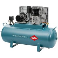
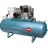
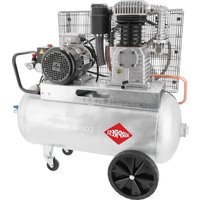
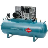
Product display of three AirPress air conditioners with visible branding (no text or symbols on the models themselves)PRO SERIES
BLACK PRO, K SERIES, HK SERIES
TABLE OF CONTENT
- Istruzioni per l'uso (IT)....20
- Instruction book (EN) 23
- Manuel d'instructions (FR) 26
- Bedienungsanleitung (DE) 29
- Manual de instrucciones (ES) 32
- Instruções de utilização (PT) 35
- Bedieningshandleiding (NL) 38
- Brugsanvisning (DK) 41
- Bruksanvisning (SV)....44
- Käyttöohjeet (FI)....47
- Εγχειρίδιο οδηγιών (GR)......50
- Instrukcja (PL) 53
- Korisnički priručnik (HR) 56
- Navodila za uporabo (SI)....59
- Használati utasítás (HU)....62
- Návod k obsluze (CZ)....65
- Návod na obsluhu (SK) 68
- Руководство по эксплуатации (RU) 71
- Bruksanvisning (NO)....74
- Kullanma talimati (TR)....77
- Manual de instructiuni (RO)....80
- Ръководство по експлоатацията (BG)....83
- Uputstva za upotrebu (RS) 86
- Naudojimo instrukcija (LT) 89
- Kasutusjuhend (EE)....92
- Instrukciju grāmata (LV) 95
- Упатство за користење (МК)....98
- Manual përdorimi (SQ)....102
- Uputstvo za upotrebu (SR) 106
- Інструкція з експлуатації (UA)......110

Attenzione! - Warning! - Attention! - Achtung! - ¡Cuidado! - Atenção! - Waarschuwing! - Advarsel! - Varning! - Varoitus! - Прогохή! - Uwaga! - Pozor! - Pozor! - Figyelem! - Pozor! - Pozor! - Внимание! - Advarsel! - Uyari! - Atenție! - Внимание! - Pažnja! - Dėmesio! - Tähelepanu! - Uzmanību! - Paralajmërim! - Увага! - Упозорење! - Пажња! - Предупредување! - Внимание! -
IT Tutti i dati identificativi, costruttore, modello, codice e numero di serie, sono riportati sull'etichetta CE applicata sull'ultima pagina del manuale.
GB All identification data: manufacturer, model, code and serial number are printed on EC label stuck onto the last page of this manual.
FR Toutes les données d'identification : fabricant, modèle, référence et numéro de série, sont indiquées sur l'étiquette CE appliquée sur la dernière page du manuel.
DE Sämtliche Gerätedaten wie Hersteller, Modell, Artikel- und Seriennummer sind auf der CE-Plakette angeführt, die auf der letzten Seite des Handbuchs abgebildet ist.
ES Todos los datos identificativos: fabricante, modelo, código y número de serie figuran en la etiqueta CE aplicada en la última página del manual.
PT Todos os dados de identificação: fabricante, modelo, código e número de série são impressos na etiqueta CE colada na última página deste manual.
NL Alle identificatiegegevens: fabrikant, model, code en serienummer zijn gedrukt op het EG-etiket dat is aangebracht op de laatste pagina van deze handleiding.
DK Alle identifikationsoplysninger: Producent, model, kode og serienummer findes på CE-mærkaten, der er anbragt på sidste side i denne manual.
SE Alla identifieringsdata, tillverkare, modell, kod och serienummer, återges i CE-märkningen, som sitter på sista sidan i manualen.
FI Kaikki tunnistustiedot, kuten valmistaja, malli, koodi ja sarjanumero löytyvät oppaan viimeisellä sivulla olevasta CE-merkinnästä.
GR Όλα τα στοιχεία ταυτότητας, κατασκευαστής, μοντέλο, κωδικός, και αριθμός σειράς, αναφέρονται στην ετικέτα CE που βρίσκεται στην τελευταία σελίδα του εγχειρίδιου χρήσης.
PL Wszystkie dane identyfikacyjne: producent, model, kod i numer seryjny zostały wskazane na oznaczeniu CE przyklejonym na ostatniej stronie niniejszej instrukcji.
HR Svi identifikacijski podaci: proizvođač, model, šifra i serijski broj su ispisani na CE etiketi koja se nalazi na posljednjoj stranici ovog priručnika.
SI Vsi identifikacijski podatki, proizvajalec, model, koda in serijska številka, so navedeni na CE oznaki, ki se nahaja na zadnji strani priročnika.
HU Az azonosításhoz szükséges adatok, úgymint gyártó, modell, kód és sorozatszám, megtalálhatók a kézikönyv utolsó oldalára ragasztott EK-címkén.
CZ Všechny identifikační údaje (výrobce, model, kód a sériové číslo) jsou vytíštěny na štítku EK nalepeném na poslední straně této příručky.
SK Všetky identifikačné údaje (výrobca, model, kód a sériové číslo) sú vytlačené na štítku EK nalepenom na poslednej strane tejto príručky.
RU Все идентификационные данные, название производителя, модель, номер и серийный номер указаны на этикетке СЕ, наклеенной на последней странице руководства.
NO Alle identifikasjonsdata: Produsent, modell, kode og serienummer er trykt på EU-merket som du finner på den siste siden i denne bruksanvisningen.
TR Tüm kimlik verileri: üretici, model, kod ve seri numarası, bu kılavuzun son sayfasına yapıştırılmış olan AT etiketi üzerine basılmıştır.
RO Toate datele de identificare, producătorul, modelul, codul și numărul de serie sunt redate pe eticheta CE aplicată pe ultima pagină a manualului.
BG Всички идентификационни данни - производител, модел, код и сериен номер - са отпечатани върху СЕ маркировката на последната страница на настоящото ръководство.
RS Svi identifikacijski podaci: proizvođač, model, šifra i serijski broj su ispisani na CE etiketi koja se nakazi na zadnjoj strani ovog priručnika.
LT Visi identifikaciniai duomenys: gamintojas, modelis, kodas ir serijos numeris, yra išspausdinti EB etiketėje, priklijuotoje paskutiniame šio vadovo puslapyje.
EE Köik identifitseerimisandmed, nagu tootja, mudel, kood ja seerianumber, on trükitud toote tagaküljel olevale EÜ märgistusele.
LV Visi identifikācijas dati: ražotājs, modelis, kods un sērijas numurs ir drukāti uz EK etiketes, kas pielīmēta šīs rokasgrāmatas pēdējā lapā.
Сите идентификации податоци: производител, модел, код и сериски број се испечатени на етикетата ЕС залепена на последната страница од ова упатство.
AL Të gjitha të dhënat e identifikimit: prodhuesi, modeli, kodi dhe numri serial janë shtypur në etiketën KE të ngjitur në faqen e fundit të këtij manuali.
UA Всі ідентифікаційні дані: виробник, модель, код і серійний номер надруковані на етикетці ЄС, наклеєній на останній сторінці цього посібника.
XS Сите идентификации податоци: производител, модел, код и сериски број се испечатени на етикетата ЕС залепена на последната страница од ова упатство.
(IT) Dichiarazione di conformità CE - (GB) Declaration of conformity EC - (FR) Déclaration de conformité CE - (DE) EG Konformitätserklärung - (ES) Declaración de conformidad CE - (PT) Declaração de conformidade CE - (NL) Verklaring van overeenstemming EEG - (DK) CE-Overensstemmelseserklæring - (SE) Försäkran om CE-överensstämmelse - (FI) CE Vaatimustenmukaisuusvakuutus - (GR) Δηλωση συμμορφωσης CE - (PL) Deklaracja zgodności WE - (HR) Izjava o sukladnosti direktivama EZ - (SI) Izjava o skladnosti ES - (HU) EK Megfelelési nyilatkozat - (CZ) ES Prohlášení o shodě - (SK) Prehlásenie ES o zhode - (RU) Декларация о соответствии нормам EO - (NO) EF-overensstemmelseserklæring - (TR) AT uygunluk beyanı - (RO) Declarație de conformitate CE - (BG) Декларация за съответствие по стандарт на EO - (RS) Izjava o sukladnosti propisima EZ - (LT) Deklaracija dėl EB reikalavimų vykdymų - (EE) Vastavusdeklaratsioon EK - (LV) Paziņojums par atbilstību EK prasībām (MK) Декларација за сообразност CE - (UK) Декларація відповідності CE - (AL) Deklarata e konformitetit CE (XS) Декларација за сообразност CE
IT La seguente dichiarazione è allegata in copia originale al compressore.
GB The following declaration is attached to the compressor in original copy.
FR La déclaration suivante est jointe en copie originale au compresseur.
DE Die gegenständliche Erklärung wird im Original dem Kompressor beigepackt.
ES La siguiente declaración se adjunta en copia original al compresor.
PT A seguinte declaração está anexada ao compressor na cópia original.
NL Een originele kopie van de onderhavige verklaring is bij de compressor gevoegd.
DK Denne erklæring vedlægges kompressoren i førsteeksemplar.
SE Följande försäkran bifogas kompressorn i originalkopia.
FI Seuraava vakuutus on liitetty kompressoriin alkuperäisenä kopiona.
GR Αυθεντικό αντίτυπο της παρακάτω δήλωσης προσαρτάται στον συμπιεστή.
PL Oryginał niniejszej deklaracji jest dołączony do sprężarki.
HR Uz kompresor je priložena kopija originala sljedeće izjave.
SI Ta izjava je v originalu priložena kompresorju.
HU Az alábbi nyilatkozat eredeti példánya a kompresszor mellékletét képezi.
CZ Následující prohlášení je přiloženo ke kompresoru v originální kopii.
SK Nasledujúce vyhlásenie je priložené ku kompresoru v originálnej kópii.
RU Оригинал декларации прилагается к компрессору.
NO Den følgende erklæringen er festet til kompressoren i original kopi.
TR Aşağıdaki beyan, orijinal nüsha olarak kompresöre iliştırilmiştir.
RO Următoarea declarație este anexată în copie originală la compresor.
BG Оригинално копие на следната декларация е прикрепена към компресора.
RS Uz kompresor je priložena kopija originala sledeće izjave.
LT Toliau pateiktos deklaracijos originali kopija pritvirtinta prie kompresoriaus.
EE Selle avalduse originaaleksemplar on kinnitatud kompressorile.
LV Sekojošas deklaracijas originälä kopija ir pievienota kompresoram.
MK Следната декларација е прикачена на компресорот во оригинална копија.
AL Deklarata e mëposhtme i është bashkëngjitur kompresorit në kopjen originale.
UA Наступна декларація додається до компресора в оригіналі.
XS Следећа декларација је приложена уз компресор у оригиналном примерку.
Il costruttore - The manufacturer - Le fabricant - der Hersteller - El fabricante - O fabricante - De fabrikant - Producent - Tillverkare - Valmistaja - O kataσκευαστής - Producent - Proizvođač - Proizvajalec - A gyártó - Výrobce - Výrobca - Производителя - Produsent - Üretici - Producătorul - Производител - Proizvođač - Gamintojas - Tootja - Ražotājs Производителот - Произвођач - Prodhuesi - Виробник
| IT | Dichiara sotto la sua esclusiva responsabilità, che il compressore d'aria qui di seguito descritto è conforme alle prescrizioni di sicurezza delle direttive applicabili. |
| GB | Declares under its sole responsibility that the air compressor described below complies with the safety requirements of applicable directives. |
| FRDE | Déclare sous son entière responsabilité que le compresseur d'air décrit ci-après est conforme aux prescriptions de sécurité des directives applicables.Erklärt unter ihrer alleinigen Verantwortung, dass der in Folge beschriebene Luftkompressor den Sicherheitsvorschriften der anwendbaren Richtlinien entspricht. |
| ES | Declara, bajo su exclusiva responsabilidad, que el compresor de aire descrito a continuación responde a las prescripciones de seguridad de las directivas aplicables. |
| PT | Declara sob a sua exclusiva responsabilidade que o compressor de ar descrito a seguir está em conformidade com as prescrições de segurança das directivas aplicáveis. |
| NL | Verklaart onder zijn eigen verantwoordelijkheid dat de hieronder beschreven persluchtcompressor in overeenstemming is met de veiligheidsvoorschriften die van toepassing zijn. |
| DK | Erklærer under eget ansvar, at luftkompressoren, der beskrives nedenfor, er i overensstemmelse med sikkerhedsforskrifterne i direktiverne. |
| SE | Försäkrar under eget ansvar att den luftkompressor som beskrivs nedan överensstämmer med de tillämpliga direktivens säkerhetsföreskrifter. |
| FI | Vakuuttaa omalla vastuullaan, että seuraavassa esitelty ilmakompressori vastaa sovellettavien direktiivien turvallisuusvaatimuksia. |
| GR | Δηλώνει με αποκλειστική δική της ευθύνη, ότι ο συμπιεστής αέρος που περιγράφεται παρακάτω ανταποκρίνεται στις προδιαγραφές ασφαλείας των οδηγιών που ισχύουν. |
| PL | Oświadcza na swojąylaczną odpowiedzialność, że opisana poniżej sprężarka spełnia wymagania w zakresie bezpieczeństwa zawarte w obowiązujących dyrektywach. |
| HR | Izjavljuje pod vlastitom odgovornošću da dolje opisani kompresor zraka udovoljava svim sigurnosnim zahtjevima važećih Direktiva. |
| SI | Izjavlja pod lastno odgovornostjo, da je v nadaljevanju opisan kompresor za zrak skladen z varnostnimi določili dozadevnih direktiv. |
| HU | Saját felelőssége tudatában kijelenti, hogy a lent megnevezett kompresszor megfelel a vonatkozó irányelvek biztonsági követelményeinek. |
| CZ | Prohlašuje s plnou odpovědností, že uvedený vzduchový kompresor vyhovuje bezpečnostním požadavkům příslušných směmic. |
| SK | Vyhlasuje na vlastnú zodpovednosť, že uvedený vzduchový kompresor vyhovuje bezpečnostným požiadavkám prislušných smerníc. |
| RU | Заявляет под свою исключительную ответственность, что воздушный компрессор, описанный ниже, отвечает всем требованиям безопасности применяемых директив. |
| NO | Erklærer under eget ansvar at luftkompressoren her beskrevet er i overensstemmelse med sikkerhetsforskriftene i de gjeldende direktivene. |
| TR | Tek sorumluluk kendisinde olmak üzere, aşağıda açıklanan hava kompresörünün, geçerli direktiflerin güvenlik gereklerine uygun olduğunu beyan eder. |
| RO | Declară pe propria răspundere că compresorul de aer descris în continuare este conform cu cerințele de siguranță ale directivelor aplicabile. |
| BG | Декларира на собствена отговорност, че описаният по-долу въздушен компресор е в съответствие с изискванията на приложимите директиви за безопасност. |
| RS | Izjavljuje pod ličnom odgovornošću da je dole opisan kompresor vazduha u skladu sa svim zahtevima bezbednosti koje propisuju važeće Direktive. |
| LT | Su visa atsakomybe pareiškia, kad žemiau aprašytas oro kompresorius atitinka taikomų direktyvų saugos reikalavimus. |
| EE | Avaldab enda täieliku vastutusega, et järgnevalt kirjeldatud ōhukompressor vastab kohaldatavate direktiivide ohutusnõuetele. |
| LV | Pilnībā apstiprina, ka tālāk minētais gaisa kompresors atbilst piemėrojamo direktīvu drošības prasībām. |
| MK | Изјавува под своја единствена одговорност дека компресорот за воздух опишан подолу е во согласност со безбедносните барања на важечките директиви. |
| AL | Deklaron něn përgjegjësině e saj tě vetme se kompresori i ajrit i përshkruar mè poshtě përputhet me kërkesat e sigurisë tě direktivave përkatëse. |
| XS | Изјављује под сопственом одговорношћу да је вздушни компресор описан у наставку у складу са безбедносним захтевима важећих директива. |
| UA | Заявляє під свою виключну відповідальність, що описаний нижче повітряний компресор відповідає вимогам безпеки, встановленим у відповідних директивах. |
IT LEGENDA SEGNALETICA DI SICUREZZA SUI PRODOTTI
GB KEY TO PRODUCT SAFETY SIGNS
FR LEGENDE DES PICTOGRAMMES DE SECURITE FIGURANT SUR LES PRODUITS
DE ERKLÄRUNG DER SICHERHEITSKENNZEICHNUNG AN DEN PRODUKTEN
ES INSCRIPCIÓN DE LA SEÑALIZACIÓN DE SEGURIDAD COLOCADA EN LOS PRODUCTOS
PT LEGENDA DA SINALÉTICA DE SEGURANÇA NOS PRODUTOS
NL VERKLARING WAARSCHUWINGSSYMBOLEN OP PRODUCTEN
DK SIGNATURFORKLARING TIL PRODUKTERNES SIKKERHEDSSKILTNING
SE FÖRKLARING TILL SÄKERHETSSYMBOLER PÅ PRODUKTERNA
FI TUOTTEITA KOSKEVAT TURVAMERKIT
GR ΥΠΟΜΝΗΜΑ ΣΗΜΑΤΩΝ ΑΣΦΑΛΕΙΑΣ ΣΤΑ ΠΡΟΪΟΝΤΑ
PL LEGENDA ZNAKÓW OSTRZEGAWCZYCH NA WYROBACH
HR ZNAKOVI ZA UPOZORENJE NA PROIZVODIMA
SI OPOZORILNI ZNAKI NA PROIZVODIH
HU A TERMÉKEKEN TALÁLHATÓ BIZTONSÁGI JELZÉSEK LISTÁJA


GB Before use, read the handbook carefully
GB Warning, hot surfaces
IT Legenda:
1 - Manufacturer's data
2 - CE mark and WEEE symbol
3 - Type / Code / Serial Number
4 - Air displacement expressed in (l/min) and (cfm)
5 - Air delivered by the compressor expressed in (l/min) and (cfm)
6 - Maximum operating pressure (bar and PSI), tank capacity (l), rotations per minute (RPM), weight (kg)
7 - Guaranteed sound power level in dB(A); Measured sound power level in dB(A)
8 - Electric data: voltage (V), frequency (Hz), absorption (A), power in (kW) and (HP)
9 - Duty cycle
10 - Declaration of origin
11 - Year of production/manufacturing
FR Légende :
natural_image
Illustration of a mechanical device with directional arrows indicating motion or force (no text or symbols)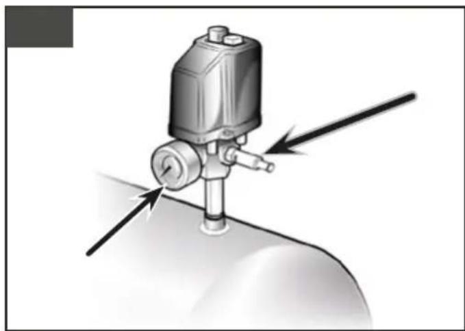
natural_image
Mechanical device with directional arrows indicating motion or force (no text or symbols)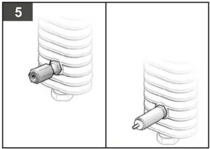
natural_image
Two-panel illustration showing a mechanical assembly with a cylindrical component inserted into a coiled spring (no text or symbols)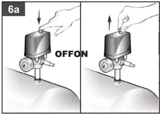
natural_image
Hand holding a cylindrical object with a pointed tip, partially visible at the bottom (no text or symbols)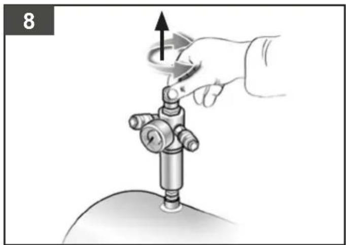
natural_image
Illustration of a hand operating a mechanical device with an upward arrow indicating rotation (no text or symbols present)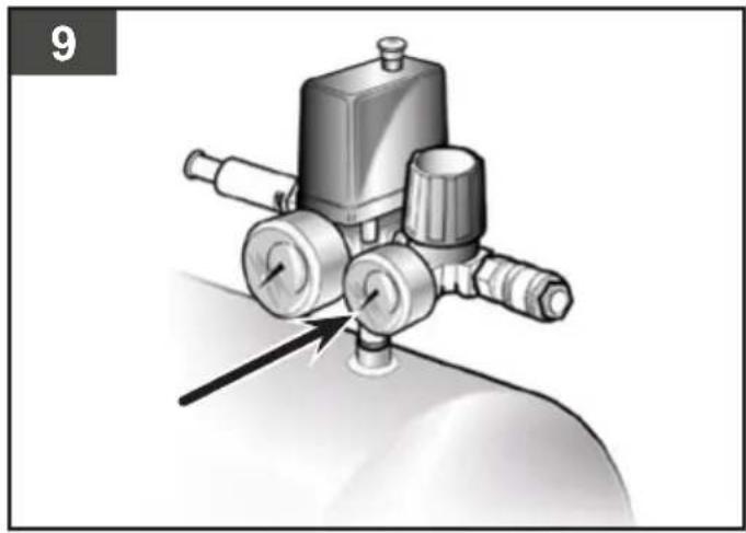
natural_image
Mechanical pressure pump assembly diagram showing valve mechanism (no text or labels)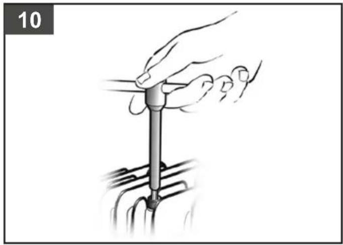
natural_image
Illustration of a hand using a tool to adjust or install a mechanical component (no text or symbols visible)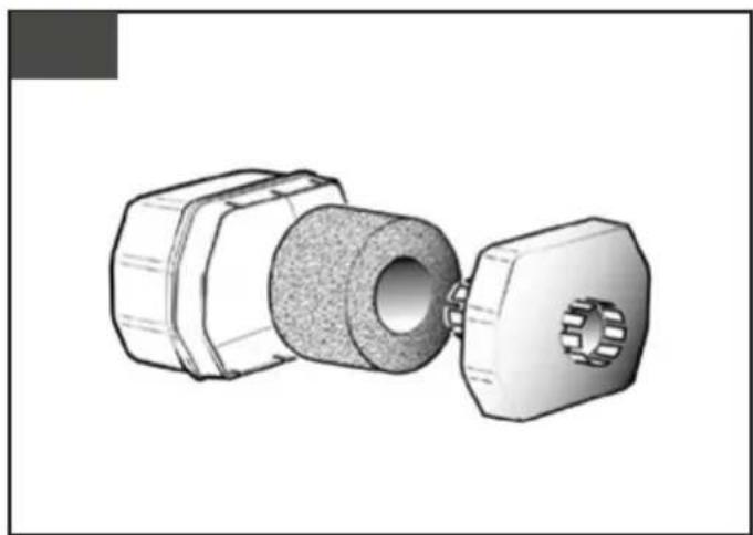
natural_image
3D technical illustration of a mechanical component with hexagonal housing and central hole (no text or symbols)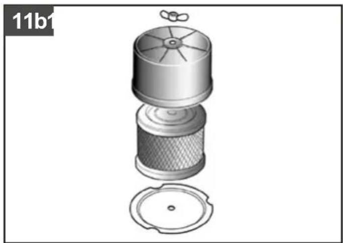
natural_image
Exploded view diagram of a mechanical component (no text or symbols)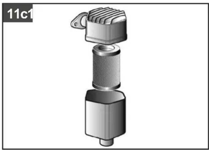
natural_image
3D rendered mechanical component with threaded shaft and hexagonal base (no text or symbols)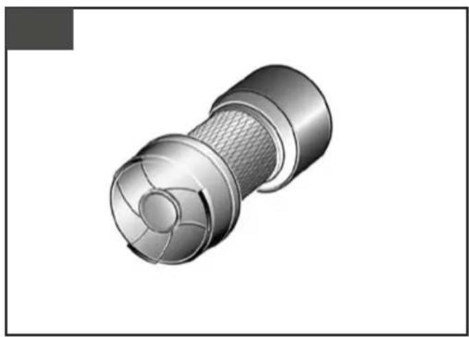
natural_image
3D rendered mechanical component with a flanged cylindrical body and internal mesh structure (no text or symbols)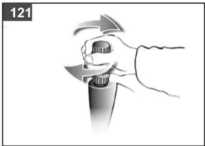
natural_image
Illustration of a hand holding a tool with directional arrows indicating motion (no text or symbols)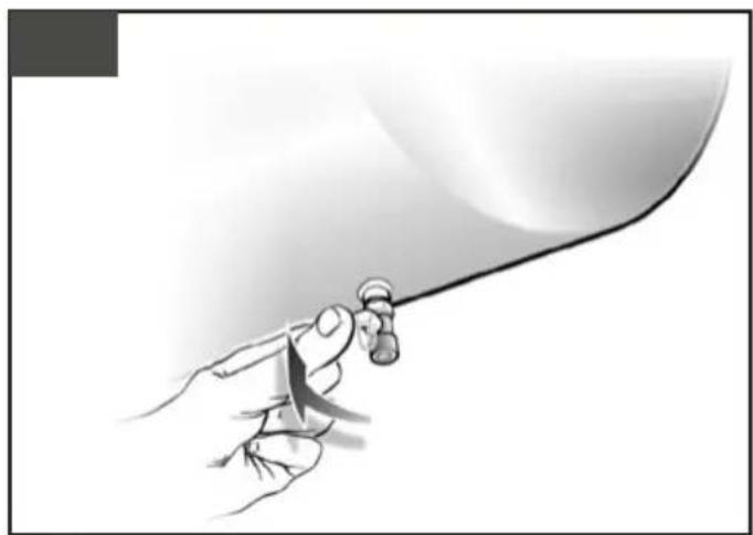
natural_image
Illustration of a hand holding a pen or tool against a curved surface (no text or symbols)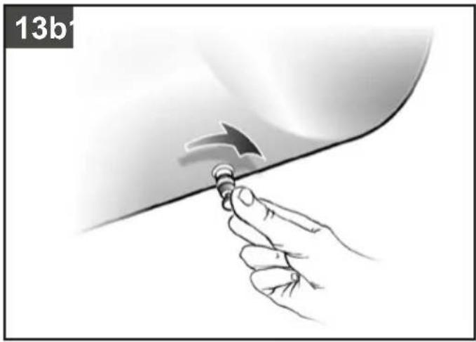
natural_image
Hand holding a screwdriver with an arrow indicating motion (no text or symbols)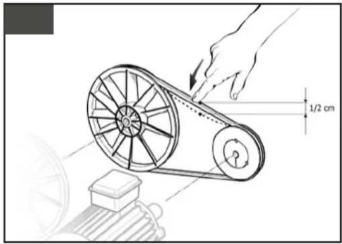
natural_image
Illustration of a hand using a wrench to adjust or install a mechanical component (no text or symbols visible)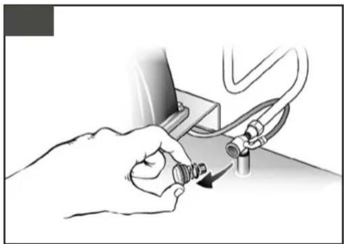
natural_image
Illustration of a hand holding a small mechanical component with a cable and pipe connection (no text or symbols)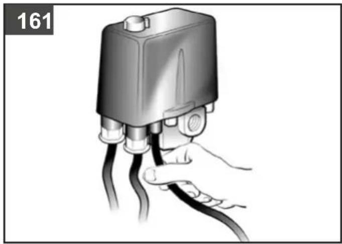
natural_image
Illustration of a hand holding a black cable with a device component, labeled '161' in the corner (no text or symbols on the diagram itself)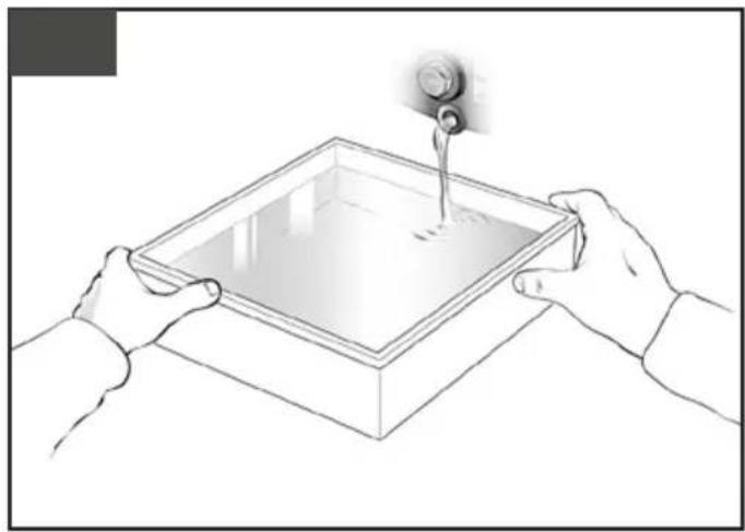
natural_image
Illustration of two hands holding a square container with liquid, pouring from a pipe into it (no text or symbols)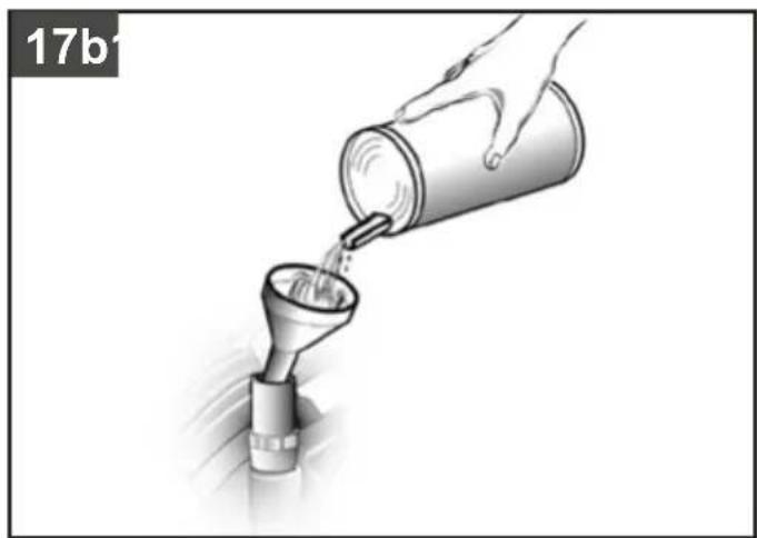
natural_image
Illustration of a hand pouring liquid from a can into a funnel (no text or symbols)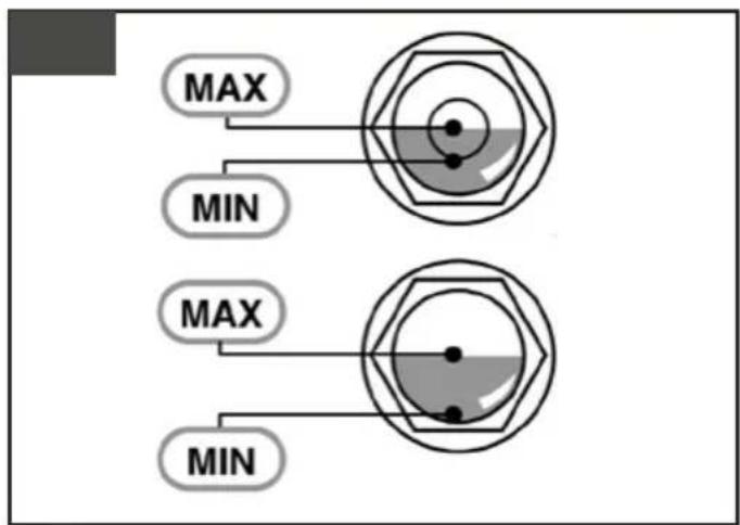
natural_image
Hand inserting a switch into an electrical fuse (no text or symbols visible)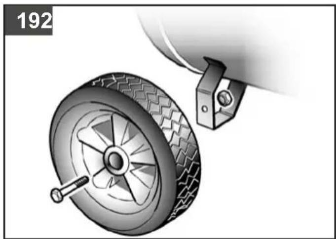
natural_image
Mechanical diagram showing a wheel and attached bracket with a pin (no text or symbols)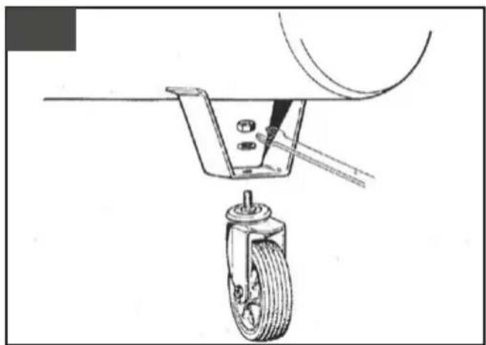
natural_image
Technical line drawing of a mechanical device with a wheel and attached bracket (no text or symbols)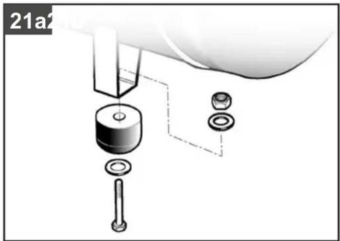
natural_image
Technical diagram of a mechanical assembly with labeled parts (no text or symbols present)1. PRECAUZIONI D'USO
These compressors are not suitable for outdoor use.
These compressors have been designed for use in professional applications.

THINGS TO DO
- The compressor must be used in a suitable environment (well ventilated with an ambient temperature between +5°C and +40°C, and relative humidity max 50% at 40°C) and never in places affected by dust, acids, vapors, explosive or flammable gases.
• Always maintain a safety distance of at least 4 meters between the compressor and the work area. - Any coloring of the belt guards of the compressor during painting operations indicates that the distance is too short.
- Insert the plug of the electric cable in a socket of suitable shape, voltage and frequency complying with current regulations.
- For 3-phase versions, have the plug fitted by a qualified electrician according to local regulations. When starting the compressor for the first time, check the correct direction of rotation and that this matches the direction indicated by the arrow on the belt guard (versions with plastic protection) or on the motor (versions with metal protection).
- Use extension cables with a maximum length of 5 meters and of suitable cross-section.
- The use of extension cables of different length and also of adapters and multiple sockets should be avoided.
- Always use the switch of the pressure switch to switch off the compressor or use the switch of the electric panel for models equipped with this. Never switch off the compressor by pulling out the plug in order to avoid restart with pressure in the head.
• Always use the handle to move the compressor. - When operating, the compressor must be placed on a stable, horizontal surface to guarantee correct lubrication.
- Position the compressor at least 50 cm from the wall to permit optimal circulation of fresh air and to guarantee correct cooling.

THINGS NOT TO DO
- Never direct the jet of air towards persons, animals or your body. (Always wear safety goggles to protect your eyes from flying objects that may be lifted by the jet).
- Never direct the jet of liquids sprayed by tools connected to the compressor towards the compressor.
- Never use the appliance in your bare feet or with wet hands or feet.
- Never pull the power cable to pull the plug out of the socket or to move the compressor.
- Never leave the appliance exposed to adverse weather conditions (rain, sun, fog, snow).
- Never transport the compressor with the reservoir pressurized.
- Never weld or machine the reservoir. In the case of faults or corrosion, replace it completely.
- Never allow inexperienced persons to use the compressor. Keep children and animals away from the work area.
- This appliance is not intended for use by persons (including children) with reduced physical, sensory or mental capabilities, or lack of experience and knowledge.
• Children should be supervised to ensure that they do not play with the appliance. -
Never position flammable or nylon or fabric articles close to and/or on the compressor.
-
Never clean the compressor with flammable liquids or solvents. Clean with a damp cloth only, after making sure that you have unplugged the compressor.
- The compressor is designed only to compress air and must not be used for any other type of gas.
- The compressed air produced by the compressor cannot not be used for pharmaceutical, food or hospital purposes except after particular treatments. It is not suitable for filling the air bottles of scuba divers.
- Never use the compressor without guards (belt guard) and never touch moving parts.

THINGS YOU SHOULD KNOW
- To avoid overheating of the electric motor, this compressor is designed for intermittent operation as indicated on the dataplate (for example, S3-50 means 5 minutes ON and 5 minutes OFF). In the case of overheating, the thermal cutout of the motor trips, automatically cutting off the power when the temperature is too high due to excess current take-off.
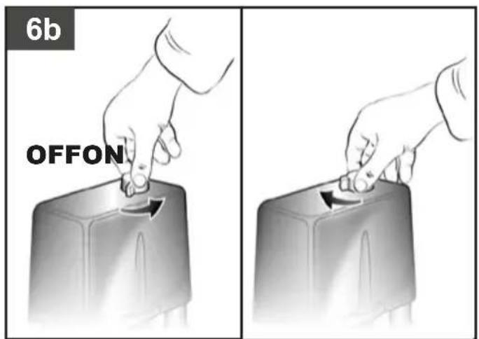
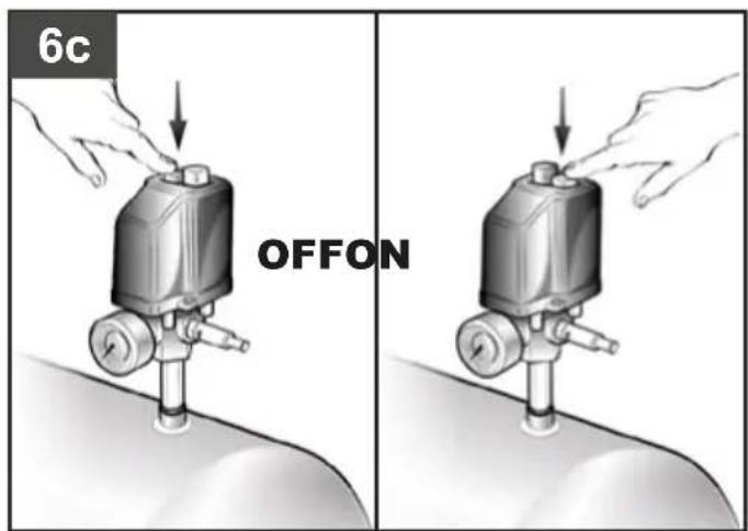
- To facilitate machine restart, it is important not only to carry out the operations indicated but also to set the button of the pressure switch, returning this to the OFF position and then ON again (figures 1a-1b).
- On single-phase versions, press the reset button on the terminal box of the motor (fig. 2).
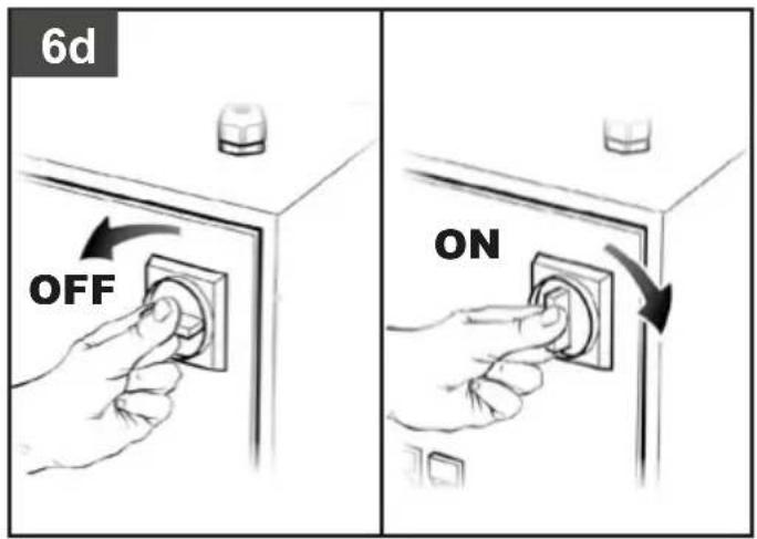
- On 3-phase versions, operate manually on the button of the pressure switch, returning this to the ON position, or press the button of the thermal cutout inside the box of the electric panel (figures 3a-3b-3c).
- The single-phase versions are fitted with a pressure switch equipped with a delayed closing air vent valve (or with a valve located on the check valve) that facilitates motor start-up; therefore a few-second jet of air from this, with the reservoir empty, is to be considered normal.
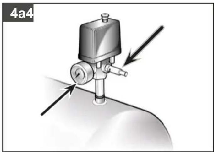
- To guarantee machine safety, all the compressors are fitted with a safety valve that is activated in the case of failure of the pressure switch (fig. 4a-4b).
- All two-stage compressors are equipped with safety valves on the air delivery manifold to the reservoir and on the connection hose between the low and high pressure located on the head. These are activated in the case of malfunctioning (fig. 5).
The safety valve is set to avoid over-pressurization of the air tanks. This valve is factory pre-set and will not function unless tank pressure reaches this pressure. Do not attempt to adjust or eliminate this safety device.
Any adjustments to this valve could cause serious injury. If this device requires service or maintenance, see an Authorized Service Center. - The red notch on the pressure gauge refers to the maximum operating pressure of the tank. It does not refer to the adjusted pressure.
- When connecting an air-powered tool to a hose of compressed air supplied by the compressor, interruption of the flow of air from the hose is compulsory.
- Use of the compressed air for the various purposes envisaged (inflation, air-powered tools, painting, washing with water-based detergents only, etc.) requires knowledge of and compliance with the rules established for each individual use.
- Please check that the air consumption and the maximum working pressure of the pneumatic tool and connection pipes (with the compressor) to be used, are compatible with the pressure set on the pressure regulator and with the amount of air supplied by the compressor.
- Supply hoses at pressures above 7 bar should be equipped with a safety cable (e.g. a wire rope).
- The compressor's performance is guaranteed for operation between 0 and 1000 meters above the sea level.
- The compressor is subject to conditioned connection with maximum impedance (Zmax) shown on the motor data plate.
2. START-UP AND USE
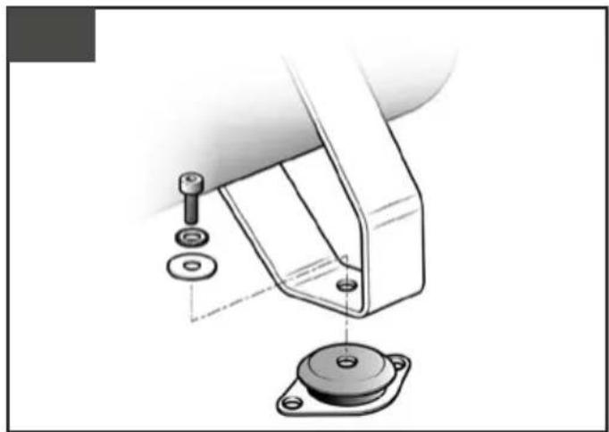
- Fit the supplied wheels as shown in figures 19 and 20. For versions with fixed feet, assemble the vibration-dampers if furnished (fig. 21).
- Check for correspondence between the compressor plate data with the actual specifications of the electrical system. A variation of ± 10% with respect of the rated value is allowed.
- Insert the power plug in a suitable socket checking that the button of the pressure switch located on the compressor is in the "O" (OFF) position (figures 6a-6b-6c-6d).
- For the 3-phase versions, connect the plug to a panel protected by suitable fuses.
- For the versions fitted with electric panel ("Tandem" control units or delta/star starters) have installation and connections (to the motor, to the pressure switch and to the electrovalve if any) carried out by qualified personnel.
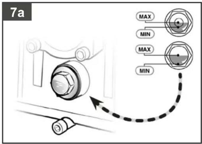
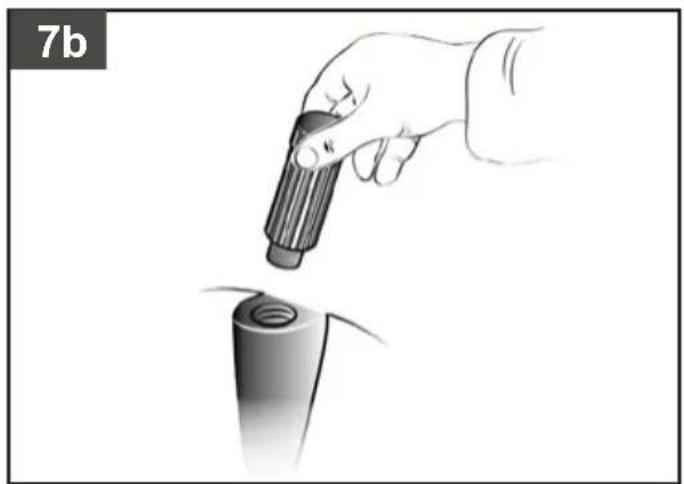
- Check the oil level using the sight glass and if necessary unscrew the vent plug and top up. (figures 7a-7b).
- At this point, the compressor is ready for use.
- Operating on the switch of the pressure switch (or the selector for versions with electric panel), (figures 6a-6b-6c-6d), the compressor starts, pumping air in the reservoir through the delivery hose. On 2-stage versions, air is sucked into the so-called low pressure cylinder liner and precompressed. It is then routed, through the recirculation hose, into the so-called high pressure liner and then into the reservoir. With this work cycle, it is possible to reach higher pressure, with availability of air at 11 bar (15 bar for special machines).
- On reaching maximum operating pressure (factory-set during testing), the compressor stops, venting the excess air present in the head and in the delivery hose through a valve located under the pressure switch (in delta/star versions, through an electrovalve that is activated when the motor stops).
- The absence of pressure in the head facilitates subsequent restart. When air is used, the compressor restarts automatically when the lower calibration value is reached (approx. 2 bar between upper and lower). The pressure inside the reservoir can be checked on the gauge provided (fig. 4a-4b).
- The compressor continues to operate automatically with this work cycle until the position of the switch of the pressure switch (or of the selector of the electric panel) (figures 6a-6b-6c-6d) is modified. To use the compressor again, wait at least 10 seconds after this has been switched off before restarting.
- In the versions with electric panel, the pressure switch must always be aligned with the I (ON) position.
- In tandem versions, the control unit provided permits use of only one of the two compressor groups (if necessary alternatively) or of both at the same time according to requirements. In this second case, start-up will be differentiated slightly to avoid excessively high current take-off at start-up (timed starting).
- Only the wheel-mounted compressors are fitted with a pressure reducer (in the versions with fixed feet, it is usually installed on the use line). Air pressure can be regulated in order to optimize use of air-powered tools operating on the knob with the valve open (pulling it up and turning it in a clockwise direction to increase pressure and counterclockwise to reduce this) (fig. 8). Once you have set the value required, push the knob down to lock it.
- The value set can be checked on the gauge (for versions equipped with this, fig. 9).
- Please check that the air consumption and the maximum working pressure of the pneumatic tool to be used are compatible with the pressure set on the pressure regulator and with the amount of air supplied by the compressor.
- When you have finished working, stop the machine, pull out the plug and empty the reservoir.
3. MAINTENANCE
- The service life of the machine depends on maintenance quality.
- PRIOR TO ANY OPERATION SET THE PRESSURE SWITCH TO THE OFF POSITION, PULL OUT THE PLUG AND COMPLETELY DRAIN THE RESERVOIR.
- Check that all screws (in particular those of the head of the unit) are tightly drawn up (fig. 10).
The control must be performed before the first start-up of the compressor and subsequently before the first intensive use in order to restore the correct closing torque value modified as a result of heat expansion.
TABLE 1 – TIGHTENING OF HEAD TENSION RODS
| NmMin. torque | NmMax. torque | |
| Screw M6 | 9 11 | |
| Screw M8 | 22 27 | |
| Screw M10 | 45 55 | |
| Screw M12 | 76 93 | |
| Screw M14 | 121 148 |
- Clean the suction filter according to the type of environment and in any case at least every 100 hours. If necessary, replace the filter (a clogged filter impairs efficiency while an inefficient filter causes harsher wear on the compressor (figures 11a - 11b-11c-11d).
-
Change the oil after the first 100 hours of operation and subsequently every 300 hours. Check the oil level periodically.
-
Use SAE 40. (For cold climates, SAE 20 is recommended). Never mix different grade oils. If the oil changes color (whitish = presence of water; dark = overheated), it is good practice to replace the oil immediately.
• After topping up, tighten the plug (fig. 12) making sure that there are no leaks during use. Once a week, check the oil level to assure lubrication in time (fig. 7a). - Periodically (or after completing work if for more than an hour), drain the condensate that forms inside the reservoir due to the humidity in the air (fig. 13a-13b) in order to protect the reservoir from rust and so as not to restrict its capacity.
- Periodically, check the tension of the belts which must have a flexion (f) of around 1 cm (fig. 14).
TABLE 2 – MAINTENANCE
| FUNCTION | AFTER THE FIRST 100 HOURS | EVERY 100 HOURS | EVERY 300 HOURS |
| Cleaning of intake filter and/or substitution of filtering element | • | ||
| Change of oil* | • | • | |
| Tightening of head tension rods | The check must be carried out prior to the first compressor starting. | ||
| Draining tank condensate | Periodically and at the end of work | ||
| Checking the tension of the belts | Periodically | ||
* Spent oil and condensate MUST BE DISPOSED OF in compliance with protection of the environment and current legislation.
4. STORAGE
Pull the mains plug out of the socket and vent the appliance and all connected pneumatic tools. Switch off the compressor and make sure that it is secured in such a way that it cannot be started up again by any unauthorized person.
5. DISPOSAL
The compressor must be disposed in conformity with the methods provided for by local regulations.
6. WARRANTY AND REPAIR
In the event of defective goods or requirements for spare parts, kindly contact the sales point where you made your purchase.
7. POSSIBLE FAULTS AND RELATED PERMITTED REMEDIES
Request the assistance of a qualified electrician for operations on electric components (cables, motor, pressure switch, electric panel, etc).
| Fault Cause Remedy | ||
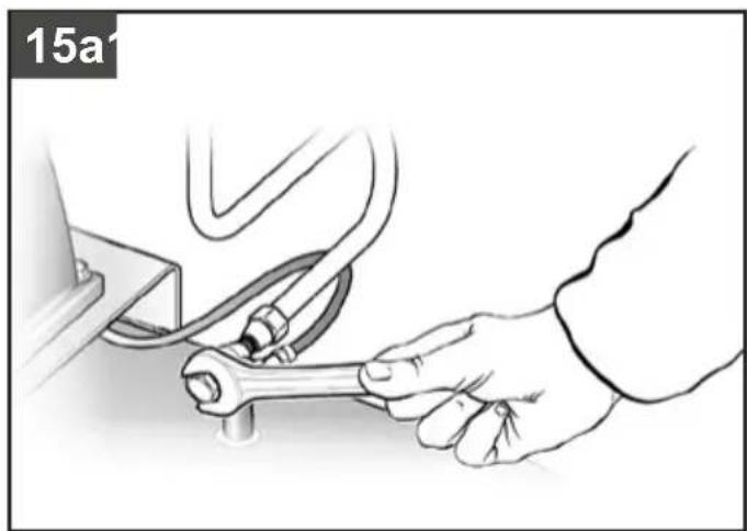
| Air leak from the valve of the pressure switch. | Check valve does not perform its function correctly due to wear or dirt on the seal. | Unscrew the hex-shaped head of the check valve, clean the housing and the special rubber disk (replace if worn). Re-assembler and tighten carefully (figures 15a-15b). |
| Condensate drainage cock open. Close the Condensate drainage cock. | ||
| Rilsan hose not inserted correctly in pressure switch. | Insert the Rilsan hose correctly inside the pressure switch (fig. 16). | |
| Reduction of efficiency, frequent start-up. Low pressure values. | Excessively high consumption. Decrease the demand of compressed air. | |
| Leaks from joints and/or pipes. Change gaskets. | ||
| Clogging of the suction filter. | Clean/replace the suction filter (figures 11a-11b-11c-11d). | |
| Slipping of the belt. Check belt tension (fig. 14). | ||
| The motor and/or the compressor overheat irregularly. | Insufficient ventilation. Improve ambient conditions. | |
| Closing of air ducts. Check and if necessary clean the air filter. | ||
| Insufficient lubrication. | Top up or change oil (figures 17a-17b-17c). | |
| After an attempt to start the compressor, it stops due to tripping of the thermal cutout caused by forcing of the motor. | Start-up with head of the compressor charged. | Release the compressor head by using the pressure switch push button. |
| Low temperature. Improve ambient conditions. | ||
| Voltage too low. | Check that the mains voltage matches that of the dataplate. Eliminate any extensions. | |
| Incorrect or insufficient lubrication. | Check level, top up and if necessary change the oil. | |
| Inefficient electrovalve. Call the Service Center. | ||
| During operation, the compressor stops for no apparent reason. | Tripping of the thermal cutout of the motor. | Check level oil. |
| Single-stage, mono-phase versions: operate on the button of the pressure switch returning this to the OFF position (fig. 1a). Reset the thermal cutout (fig. 2) and restart (figures 1b). If the fault persists, call the Service Center. | ||
| Versions with delta-star starter: operate on the button of the thermal cutout located inside the box of the electric panel (fig. 3c) and restart (fig. 6d). If the fault persists, call the Service Center. | ||
| Other versions: Operate on the button of the pressure switch returning this to the OFF position and then to ON again (fig. 1a-1b). If the fault persists, call the Service Center. | ||
| Electric fault. Call the Service Center. | ||
| When operating, the compressor vibrates and the motor emits an irregular buzzing sound. If it stops, it does not restart although the sound of the motor is present. | Single-phase motors: faulty capacitor. | Have the capacitor replaced. |
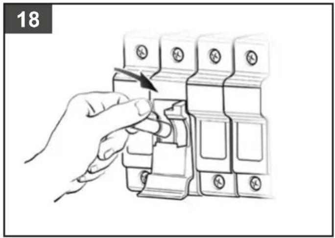
| 3-phase motors: One of the phases of the 3-phase power supply is missing due probably to blowing of a fuse. | Check the fuses inside the electric panel or the electric box and if necessary replace those that have been damaged (fig. 18). | |
| Irregular presence of oil in the network. | Too much oil inside the unit. Check oil level. | |
| Wear on segments. Call the Service Center. | ||
| Leaking of condensate from the drain valve. | Presence of dirt/grit inside the drain valve. | Clean the drain valve. |
Any other type of operation must be carried out by authorized Service Centers, requesting original parts. Tampering with the machine may impair its safety and in any case make the warranty null and void.
1. PRECAUTIONS D'UTILISATION
7. POSSIBLES ANOMALIES ET INTERVENTIONS ADMISES
6. GARANTIE EN REPARATIE
TAULUKKO 2 – HUOLTOVÄLIT
6. GWARANCJA I NAPRAWA
TABELL 1 – STRAMMING AV HOLDER FOR MUNNSTYKKET
| NmMin. moment | NmMaks. moment | |
| Bolt M6 | 9 11 | |
| Bolt M8 | 22 27 | |
| Bolt M10 | 45 55 | |
| Bolt M12 | 76 93 | |
| Bolt M14 | 121 148 |
TABELL 2 - VEDLIKEHOLDSINTERVALLER
- PRO SERIES
- BLACK PRO, K SERIES, HK SERIES
- TABLE OF CONTENT
- IT Legenda:
- FR Légende :
- PRECAUZIONI D'USO
- THINGS TO DO
- THINGS NOT TO DO
- THINGS YOU SHOULD KNOW
- START-UP AND USE
- MAINTENANCE
- STORAGE
- DISPOSAL
- WARRANTY AND REPAIR
- POSSIBLE FAULTS AND RELATED PERMITTED REMEDIES
- PRECAUTIONS D'UTILISATION
- POSSIBLES ANOMALIES ET INTERVENTIONS ADMISES
- GARANTIE EN REPARATIE
- GWARANCJA I NAPRAWA
Brand : Airpress
Model : K 200-450
Category : Compressor