KM 130/300 R I LPG - Sweeper Kärcher - Free user manual and instructions
Find the device manual for free KM 130/300 R I LPG Kärcher in PDF.

| Product type | Rider sweeper |
| Brand | Kärcher |
| Model | KM 130/300 R I LPG |
| Working width without side broom | 1000 mm |
| Working width with 1 side broom | 1300 mm |
| Working width with 2 side brooms | 1550 mm |
| Travel speed (forward/reverse) | 10 km/h |
| Maximum gradeability | 18% |
| Turning radius | 2.8 m |
| Dimensions (L x W x H) | 2040 x 1330 x 1430 mm |
| Empty weight | 920 kg |
| Total permissible weight | 1530 kg |
| Dust hopper volume | 300 L |
| Maximum dump height | 1400 mm |
| Engine type | Kubota WG 972-E4, 3-cylinder, 4-stroke, water-cooled |
| Engine power | 17.5 kW / 23.5 HP |
| Fuel | LPG (propane/butane) |
| Gas tank capacity | 11 kg (interchangeable bottle) |
| Battery | 12 V, 60 Ah, maintenance-free |
| Filtration system | Pocket filter, surface area 7.8 m² |
| Sound pressure level (LpA) | 80 dB(A) |
| Guaranteed sound power level | 101 dB(A) |
| Main functions | Sweeping, high dump, automatic filter cleaning |
| Maintenance | Daily and weekly checks; maintenance by authorized service |
| Safety | Parking brake, seat switch, gas safety, optional protective canopy |
| Spare parts | Original Kärcher accessories and spare parts |
Frequently Asked Questions - KM 130/300 R I LPG Kärcher
User questions about KM 130/300 R I LPG Kärcher
0 question about this device. Answer the ones you know or ask your own.
Ask a new question about this device
Download the instructions for your Sweeper in PDF format for free! Find your manual KM 130/300 R I LPG - Kärcher and take your electronic device back in hand. On this page are published all the documents necessary for the use of your device. KM 130/300 R I LPG by Kärcher.
USER MANUAL KM 130/300 R I LPG Kärcher
natural_image
Exterior view of a Karcher cleaning robot with visible brush and control panel (no text or symbols on the device itself)Deutsch 7
English 22
Français 37
Italiano 52
Español 68
Português 83
Nederlands 99
Türkçe 114
Svenska 129
Suomi 143
Norsk 157
Dansk 171
Eesti 185
Latviešu 200
Lietuviškai 215
Polski 229
Magyar 245
Čeština 260
Slovenčina 275
Slovenščina 290
Română 305
Hrvatski 320
Srpski 334
Ελληνικά 349
Русский 365
Українська 382
Қазақша 398
Български 414
日本語 430
中文 444
العربيya 458
A
natural_image
Close-up of a red gas stove burner with a valve and tubing, no visible text or symbols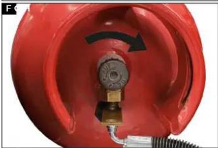
natural_image
Close-up of a red industrial component with a black arrow indicating rotation, no visible text or symbols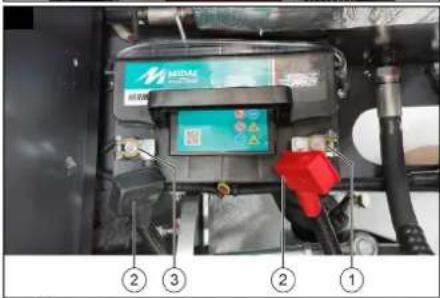
natural_image
Close-up of a red pipe fitting with a white plastic housing and metal fittings, labeled with numbers 1, 2, and 3 (no text or symbols on the diagram itself)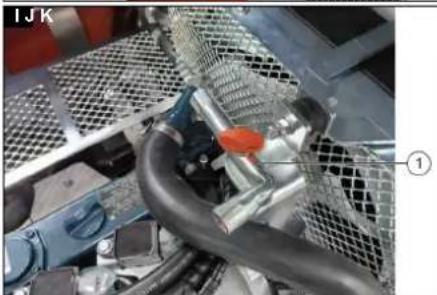
natural_image
Close-up of a mechanical assembly with hoses and meshed components (no visible text or symbols)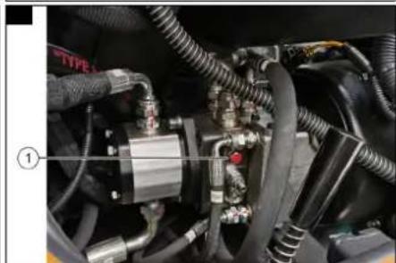
natural_image
Close-up of industrial machinery components with hoses and tubing (no visible text or symbols)
natural_image
Control panel with digital display and multiple yellow buttons, no visible text or symbols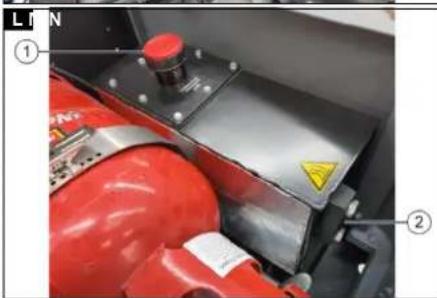
natural_image
Close-up of a metallic surface with two numbered points and textured patterns, no visible text or symbols.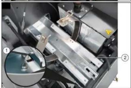
natural_image
Close-up of a mechanical assembly with metallic components and a magnified inset showing a detail (no visible text or symbols)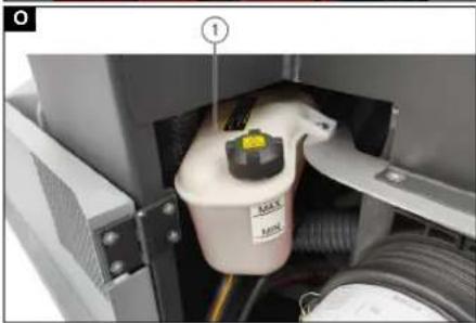
natural_image
Interior view of an industrial equipment enclosure showing a central component with labeled parts (no readable text or symbols)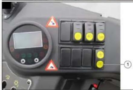
natural_image
Control panel of a tractor with yellow buttons and warning symbols (no readable text or labels)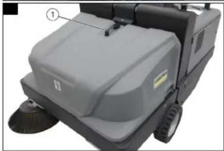
natural_image
Close-up of a cleaning or cleaning machine with visible brush and handle (no text or symbols)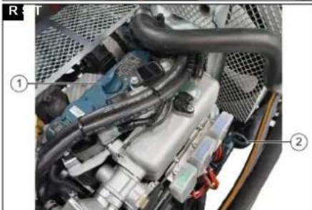
natural_image
Close-up of an automotive engine bay with visible components and wiring (no text or symbols)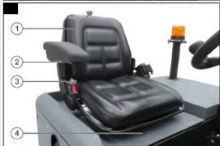
natural_image
Interior view of a mechanical or electrical enclosure with two labeled components (① and ②), showing no visible text or symbols.U
FU01 FU02 FU03 FU04 FU05 FU06
FU07 FU08 FU09 FU10 FU11 FU12

natural_image
Interior view of an automotive engine bay with visible components and wiring (no text or symbols)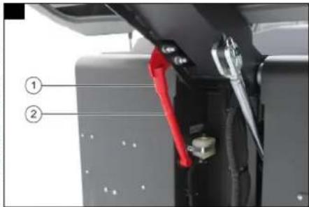
natural_image
Close-up of a mechanical assembly with visible components and wiring (no readable text or symbols)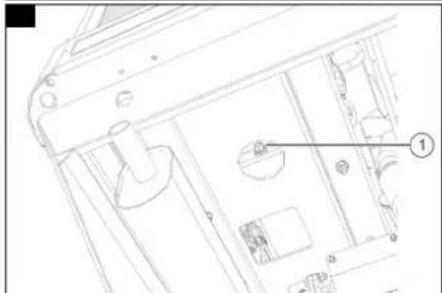
natural_image
Technical line drawing of a mechanical component with no visible text or symbols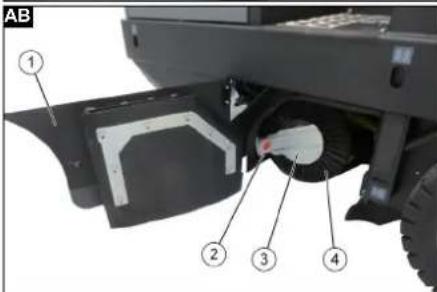
natural_image
Close-up of a white mechanical component with radial blades and a colorful strip, no visible text or symbols.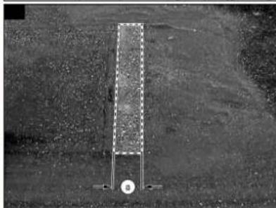
natural_image
Aerial view of a rectangular structure with a circular base and directional arrows, set against a textured ground background (no text or symbols visible)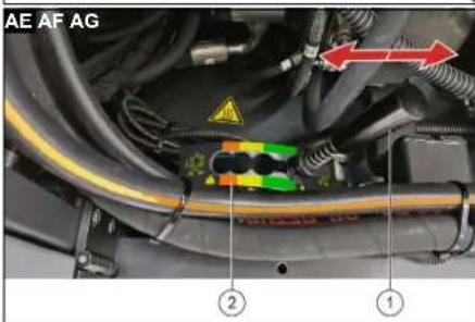
natural_image
Close-up of a circular object with a pointed edge and labeled point 'a' on a textured surface, next to a spool-like structure (no readable text or symbols)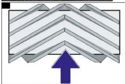
natural_image
Abstract geometric pattern with layered chevron shapes and a blue upward arrow (no text or symbols)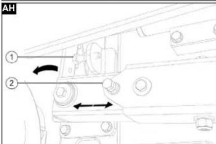
natural_image
Close-up of a cylindrical mechanical component with internal threading, labeled parts ① and ② (no readable text or symbols)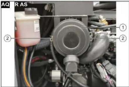
natural_image
Technical line drawing of a mechanical assembly with gears and linkages (no text or symbols)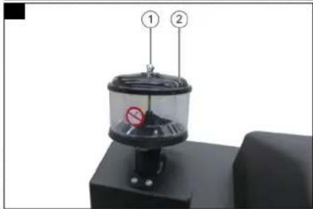
Inhalt
71364 Winnenden (Germany)
Tel.: +49 7195 14-0
Fax: +49 7195 14-2212

Chairman of the Board of Management

S. Reiser
Manager Regulatory Affairs & Certification
Winnenden, 2021/05/01
Alfred Kärcher SE & Co. KG
Alfred-Kärcher-Str. 28 - 40
71364 Winnenden (Germany)
Tel.: +49 7195 14-0
Fax: +49 7195 14-2212
Technische Daten
| General notes | 22 |
| Safety instructions | 22 |
| Environmental protection | 25 |
| Intended use | 25 |
| Accessories and spare parts | 25 |
| Scope of delivery | 25 |
| Device description | 25 |
| Function | 26 |
| Precommissioning | 26 |
| Initial startup | 27 |
| Operation | 27 |
| Transport | 28 |
| Storage | 29 |
| Care and maintenance | 29 |
| Troubleshooting guide | 34 |
| Warranty | 34 |
| EU Declaration of Conformity | 35 |
| Technical data | 35 |
General notes
| Read the original instructions before using the device for the first time and act in accordance with it. Keep the original instructions for future reference or for future owners. |
Safety instructions
Hazard levels
DANGER
- Indication of an imminent threat of danger that will lead to severe injuries or even death.
⚠ WARNING
- Indication of a potentially dangerous situation that may lead to severe injuries or even death.
△CAUTION
- Indication of a potentially dangerous situation that may lead to minor injuries.
ATTENTION
- Indication of a potentially dangerous situation that may lead to damage to property.
Symbols on the machine
 | ATTENTIONDanger of burnsBefore working on hot vehicle parts, allow them to cool down. |
 | △DANGERRisk of fireDo not sweep up burning or glowing objects such as cigarettes, matches or similar objects. |
 | △WARNINGRisk of injuryRisk of crushing and shearing due to moving vehicle parts. |
 | △WARNINGRisk of injuryCut and crush injuries from moving vehicle parts inside.Do not reach into openings in the device. |
 | Always wear suitable gloves when carrying out work on the vehicle. |
 | Do not clean the component with spray water. |
 | Beware of rotating brushes. |
 | Only drive in the direction of travel, uphill and downhill gradients up to 18%. |
 | Maximum inclination of the ground when travelling with a raised waste container. |
 | Ensure that the extraction valve is orientated correctly. |
 | Jacking point |
 | Fastening point |
Safety instructions for operation
⚠ WARNING ● Only use the device for its proper use. Take into account the local conditions and beware of third parties, in particular children, when working with the device. ● Check the device with the operating devices to make sure it is in proper condition and operational safe and reliable. If it is not in perfect condition, you must not use it. ● Adhere to the respective safety regulations in hazard zones (e.g. service stations). Never operate the device in explosive spaces. ● The device is not intended for use by persons with restricted physical, sensory or mental abilities or those lacking in experience and / or lacking in knowledge.
- Only people who have been instructed on how to use the device, or have proven their ability to operate it, and have been explicitly instructed to use it, must use the device. ATTENTION
- Before starting work, the operator must check whether the safety devices have been attached properly and are fully functional.
- The device operator is responsible for accidents with other people and their property.WARNING • The operator must wear close-fitting clothing and sturdy footwear. Avoid loose-fitting clothing. • Children must be supervised to prevent them from playing with the appliance. • Children and minors must not use the device.ATTENTION • Check the immediate vicinity before setting off (e.g. children). Make sure you have a sufficient view.DANGER • Never leave the device unattended unless the device is secured against unintentional movement. Always apply the parking brake before leaving the device.ATTENTION • Remove the ignition key or KIK (Kärcher Intelligent Key) to prevent unauthorised use of the device.CAUTION • Do not use the device in areas in which there is a possibility of being struck by falling objects.WARNING • Do not look directly into the light source on devices equipped with Blue Spot lighting.
Safety instructions for driving
Note • The list on the risk of overturning is not necessarily comprehensive. DANGER • Danger of tilting if hill or slope is too steep! Observe the maximum permissible values in the technical data when driving up hills and slopes. • Danger of tilting in case of excessive tilting at side! Observe the maximum permissible values in the technical data when driving lateral to the travel direction. • Danger of tilting on unstable subsurfaces! Only use the device on firm subsurfaces.
⚠ WARNING ● Risk of accident due to not adapting speed. Approach corners slowly.
Safety instructions for transporting
△ CAUTION ● To avoid accidents during transport, observe the transport weight of the vehicle. ● To transport the machine, disconnect the battery and securely fasten the machine.
Safety instructions for the batteries
Observe accident prevention guidelines and DIN VDE 0510, VDE 0105 T.1.
Be sure to observe the following warnings when handling the batteries:

Observe the notes on the battery, in the instructions and in the vehicle operating instructions!

Wear eye protection!

Keep acids and batteries away from children.
Risk of explosion!
Fire, sparks, open flames and smoking are prohibited!
Risk of acid burns!

First aid!

Warning note!

Disposal!
Do not throw batteries in the bin!
△DANGER
Risk of fire and explosion!
Do not place tools or similar items on the battery. Short-circuit and risk of explosion.
Open flames and smoking must be strictly avoided.
Rooms in which batteries are charged must be well ventilated, as highly explosive gas is produced during charging.
⚠ WARNING
Risk of acid burns!
Use caution with leaking batteries (sulphuric acid may leak).
△WARNING
Risk of poisoning!
Never bring wounds into contact with lead. Always clean your hands after working on batteries.
Safety instructions for sweepers with high dumping
△ DANGER ● Risk of injury on sweepers with high dumping Secure the lifted waste container before working. Fit the retainer only from outside the hazard zone.
Safety instructions for sweepers with combustion engine
ATTENTION • The exhaust opening must not be sealed off. CAUTION • Do not reach into the area of the exhaust opening. (Danger of burns) Do not touch the drive motor during operation. (Danger of burns) Avoid inhaling exhaust fumes at all costs. The engine has a run-on time of 3 -4 seconds after switching off. Do not touch moving parts during this period.
Safety instructions for liquid gas vehicles
In addition to the information in these operating instructions, the locally applicable regulations, provisions and directives must be complied with when handling vehicles fuelled with liquid gas and when handling and storing the gas cylinders used.
Safety guidelines for liquid gas vehicles
Liquid gases (propellants) are butane and propane or butane/propane mixtures. They are supplied in special bottles. The operating pressure of these gases depends on the outside temperature.
Only use liquid gas cylinders filled with propellant gas in accordance with DIN 51622 quality. The use of household gas and camping gas is generally prohibited. Liquid gas mixtures can be different for different gas motors. The approved liquid gas mixtures can be found in the technical data.
△DANGER
Risk of explosion
Do not treat liquid gas like petrol. Petrol vaporises slowly, liquid gas becomes gaseous immediately. The risk of gasification and ignition is therefore greater with liquid gas than with petrol.
Duties of management and employees
- All persons who have to handle liquid gas are obliged to acquire the knowledge of the characteristics of liquid gases required for the safe operation of the system. This publication must be carried with the sweeper at all times.
Service by the expert
- Propellant gas systems must be checked at regular intervals, but at least once a year, by an expert to ensure that they are functioning properly and are leak-tight (in accordance with DGUV principle 310-004).
- The examination must be certified in writing. The basis for testing is DGUV 110-010 "Use of liquid gas".
- Relevant local standards and guidelines for the testing of vehicles whose engines run on liquid gases apply as general regulations for testing.
Initial startup / operation
- Gas may only be drawn from one cylinder at a time. If gas is withdrawn from several cylinders at the same time, the liquid gas may transfer from one cylinder to another. As a result, the overfilled cylinder is exposed to an impermissible increase in pressure after the cylinder valve is closed.
- Note the installation position of the gas connection during installation of the full bottle, further information in chapter "Installing the gas bottle".
Replace the gas cylinder carefully. During installation and removal, the gas outlet nozzle of the cylinder valve must be sealed by a locking nut tightened with a spanner.
- Leaking gas cylinders must not be reused. They must be emptied immediately by releasing them out in the open, taking all precautionary measures, and then labelled as leaking. When delivering or collecting damaged gas cylinders, the lender or its representative (petrol station attendant or similar) must be informed immediately in writing of the existing damage.
- Before connecting the gas cylinder, check that the connection nozzle is in good condition.
- After connecting the cylinder, it must be checked for leaks using foaming agents.
- The valves should be opened slowly. Opening and closing must not be carried out with the aid of impact tools.
- Only extinguish liquid gas fires from a safe distance and under cover.
- Only use dry carbon dioxide extinguishers or carbon dioxide gas extinguishers.
- Use plenty of water to cool the gas container.
- The entire liquid gas system must be continuously monitored to ensure that it is in a safe operating condition, especially with regard to leaks. The use of the vehicle with a leaking gas system is prohibited.
- Close the cylinder valve before loosening the pipe or hose connection. The connection nut on the cylinder should be loosened slowly and only slightly at first, otherwise the pressurised gas still in the line will escape spontaneously.
- If the gas is refuelled from a large container, the relevant regulations must be obtained from the respective liquid gas wholesaler.
△DANGER
Risk of injury
Liquid gas in liquid form causes frost wounds on bare skin.
- After removal, the cap nut must be screwed tightly onto the connection thread of the cylinder.
- Soapy water, nekal or other foaming agents should be used to test for leaks. Lighting the liquid gas system with an open flame is prohibited.
- The manufacturer's installation instructions must be observed when replacing individual system components. The cylinder and main shut-off valves must be closed.
- The condition of the electrical system of the liquid gas vehicles must be monitored continuously. Sparks can cause explosions if there are leaks in the gas-carrying parts of the system.
- After a prolonged shutdown of a liquid gas motor vehicle, the parking area must be thoroughly ventilated before an initial startup of the vehicle or its electrical systems.
- Accidents in connection with gas cylinders or the liquid gas system must be reported immediately to the employers' liability insurance association and the responsible labour inspectorate. Damaged parts must be kept until the investigation has been completed.
In the adjustment and storage rooms as well as the repair workshops
- Propellant or liquid gas cylinders must be stored in accordance with the regulations TRF 2021 (Technical Rules for Liquid Gas, see DA for DGUV Rule 110-010).
- Gas cylinders must be stored upright. Handling open flames and smoking at the installation site of containers and during repairs is not permitted. Cylinders placed outdoors must be secured against access. Cylinders bottles must always be sealed.
- The cylinder and main shut-off valves must be closed immediately after the vehicle has been parked.
- The provisions of TRGS 510, the locally applicable garage regulations and the locally applicable building regulations apply to the location and condition of the parking spaces for liquid gas vehicles.
- The gas cylinders must be stored in special rooms separate from the storage rooms (see DA to DGUV Rule 110-010).
- The electric hand lamps used in the rooms must be fitted with a closed, sealed cover and a strong protective cage.
- When working in repair workshops, the cylinder and main shut-off valves must be closed and the propellant cylinders must be protected against the effects of heat.
- Before breaks in operation and before closing time, a responsible person must check that all valves, especially cylinder valves, are closed. Fire work, especially welding and cutting work, must not be carried out in the vicinity of propellant gas cylinders. Propellant gas cylinders, even if they are empty, must not be stored in the workshops.
- The adjustment and storage rooms as well as the repair workshops must be well ventilated. It should be noted that liquid gases are heavier than air. They accumulate on the ground, in working pits and other depressions in the ground and can form explosive gas-air mixtures.
Safety instructions for sweepers with overhead guard △CAUTION
Check the overhead guard for damage every day to ensure that it is protected.
If the overhead guard, as well as individual elements, should be damaged, the entire overhead guard must be replaced.
Any modification of the overhead guard and installation of elements, components and assemblies other than those approved by Kärcher is not permitted and may limit the function of the overhead guard.
Care and service
△ WARNING • Disconnect the battery before working on the electrical system. • Before cleaning, maintenance, replacing parts and resetting to another function, you must switch off the device and remove the ignition key.
△ CAUTION ● Repairs may only be carried out by approved customer service sites or staff qualified in this area who are familiar with all relevant safety instructions.
ATTENTION • Adhere to the safety inspection requirements for mobile devices for industrial use in accordance with the locally
applicable regulations (e.g. in Germany: VDE 0701). ● Short-circuits or other damage. Do not clean the device with a hose or high-pressure water jet. ● Always wear suitable gloves when working on the device.
Environmental protection

The packing materials can be recycled. Please dispose of packaging in accordance with the environmental regula-

Electrical and electronic devices contain valuable, recyclable materials and often components such as batteries, rechargeable batteries or oil, which - if handled or disposed of incorrectly - can pose a potential danger to human health and the environment. However, these components are required for the correct operation of the device. Devices marked by this symbol are not allowed to be disposed of together with the household rubbish.
Notes on the content materials (REACH)
Current information on content materials can be found at: www.kaercher.de/REACH
Intended use
The sweeper is intended for cleaning floor areas for commercial use and for the following areas of application, for example:
- Parking spaces
- Logistics areas
Hotels - Retail trade
- Storage areas
- Footpaths
• Production systems
This sweeper is designed for cleaning soiled surfaces in outside areas and in well-ventilated indoor areas.
Operation of the machine above an altitude of 1,200 metres above sea level is not intended.
Check that the device and work equipment is safe and working correctly prior to each use. If it is not in perfect condition, it must not be used.
Only use the sweeper in accordance with the information in these operating instructions.
The device must not be modified.
The device is only suitable for use on the coats listed in the operating instructions.
Only areas approved for machine use by the employer or their authorised representative may be driven on.
In general: Keep highly flammable substances away from the device (explosion/fire hazard).
Foreseeable misuse
- Never sweep up or vacuum explosive liquids, inflammable gases or undiluted acids and solvents. These include petrol, paint thinners or heating oil, which can form explosive vapours or mixtures through suction air turbulence, also acetone, undiluted acids and solvents because these attack the materials used in the machine.
- Never sweep or suction up reactive metal dusts (e.g. aluminium, magnesium, zinc). They form explosive gases in conjunction with highly alkaline or acidic cleaning agents.
- Do not sweep up or vacuum burning or smouldering objects.
- The device is not suitable for sweeping up substances that are hazardous to health.
- The machine may not be used in an enclosed room.
- Standing in hazard zones is prohibited. Operation in explosive spaces is prohibited.
- Carrying passengers is prohibited.
- This device must not be used to push/pull or transport objects.
Suitable sweeping surfaces
- Asphalt
- Industrial floor
- Screed
- Concrete
- Paving stones
Accessories and spare parts
Only use original accessories and original spare parts. They ensure that the appliance will run fault-free and safely. Information on accessories and spare parts can be found at www.kaercher.com.
Scope of delivery
The scope of delivery for the appliance is shown on the packaging. Check the contents for completeness when unpacking. If any accessories are missing or in the event of any shipping damage, please notify your dealer.
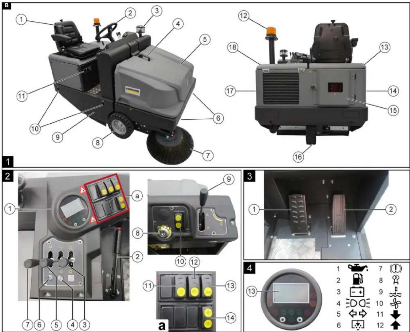
Device description
Device illustration
Illustration B
Sweeper
Position 1
①Seat (with seat contact switch)
② Steering wheel
③Centrifugal separator
④Handle with lock
⑤Cover
⑥ Working light
⑦Side brush (right)
⑧Front wheel
⑨ Roller brush access
⑩ Lashing point
⑪ Type plate
⑫Flashing beacon
⑬Device bonnet (right)
⑭ Cover (right)
⑮Rear panelling
⑯Rear wheel
⑰ Cover (left)
⑱Bonnet
Control panel
Item 2
①Control elements and display
②Parking brake
③Control lever for lifting/lowering the roller brush
④Indicator light for waste container flap
⑤Control lever for opening/closing the container flap
⑥Indicator light for fully lowered waste container
⑦Control lever for lifting/lowering the waste container
⑧Key switch (ignition lock)
⑨Control lever for lifting/lowering the side brushes
⑩Driving direction switch
⑪Flashing beacon switch
⑫ Working light switch
⑬Horn switch
⑭Switch for blower / filter cleaning
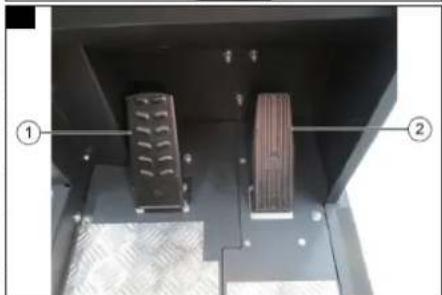
Pedals
Position 3
①Brake pedal
②Accelerator pedal
Control elements and display
Position 4
①Oil pressure warning light
②Fuel reserve indicator light
③Battery charge warning light
④Working light indicator light
⑤Turn signal indicator light (function only with StVZO conversion)
⑥Filter cleaning indicator light
⑦Parking indicator light
⑧ No function
⑨Cooling water temperature warning light
⑩Blower indicator light
⑪Low engine speed button
⑫High engine speed button
13Display
Optional equipment
| Comfort cabin (closed) 2.853-201.7 | |
| Protective cabin (open) with windscreen and windscreen wiper | 2.851-269.7 |
| Protective cabin 2.851-267.7 | |
| Overhead guard 2.852-595.7 | |
| Puncture-proof tyres (non-marking) 4.515-328.0 | |
| Tyres (air-filled) 4.515-332.0 | |
| Blue spotlight (front) 2.853-202.0 | |
| Blue spotlight (front and rear) 2.853-203.0 | |
| Tail light 2.853-204.0 | |
| Standard lights kit | 2.853-205.0 |
| Road traffic lights kit | 2.853-207.0 |
| Road approval kit (StVZO) | 2.853-208.0 |
| Seat belt | 6.981-140.0 |
| Second side brush (left) | 2.851-273.0 |
| Speed control for side brush (right) | 2.853-507.0 |
| Side brush cover | 2.851-286.0 |
| Water spray system for side brushes | 2.853-214.0 |
| Rubber shock absorber | 2.852-620.0 |
| Side brush ram protection (right) | 2.853-211.0 |
| Side brush ram protection (on both sides) | 2.853-210.0 |
| Wet/dry vacuum cleaner attachment kit NT 22/1 Bp | 2.852-814.0 |
| Wet/dry vacuum cleaner attachment kit NT 22/1 Bp (cabin) | 2.853-161.0 |
| Attachment kit for sweeping light waste | 2.853-212.0 |
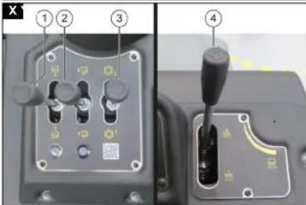
Control lever
Illustration X
①Control lever for waste container
②Control lever for container flap
③Roller brush control lever
④Control lever for side brushes
Note
Hold the levers in the desired position until the respective mechanical movement has been completed.
Control lever for waste container
| To the rear | Raising the waste container |
| To the front | Lowering the waste container |
Roller brush control lever
| To the rear | Raise the roller brush |
| To the front | Lowering the roller brush |
Control lever for container flap
| To the rear | Closing the container flap |
| To the front | Opening the container flap |
Control lever for side brushes
| To the rear | Raise the side brush |
| To the front | Lowering the side brushes |
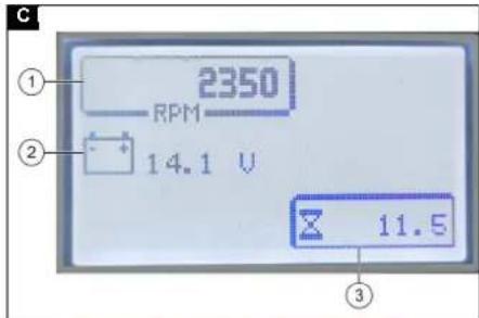
Display
Illustration C
①Engine speed in 1/min
②Voltage of the battery in V
③Operating hours of the machine
Function
The sweeper operates using the dustpan principle.
- The rotating side brushes clean corners and edges of the sweeping surface and convey the waste into the path of the roller brush.
- The rotating roller brush conveys the waste directly into the waste container.
- The dust swirled up in the waste container is separated by a dust filter, and the suction fan sucks away the filtered air.
- The dust filter is cleaned automatically during operation and can also be started using the "Filter cleaning" switch.
Precommissioning
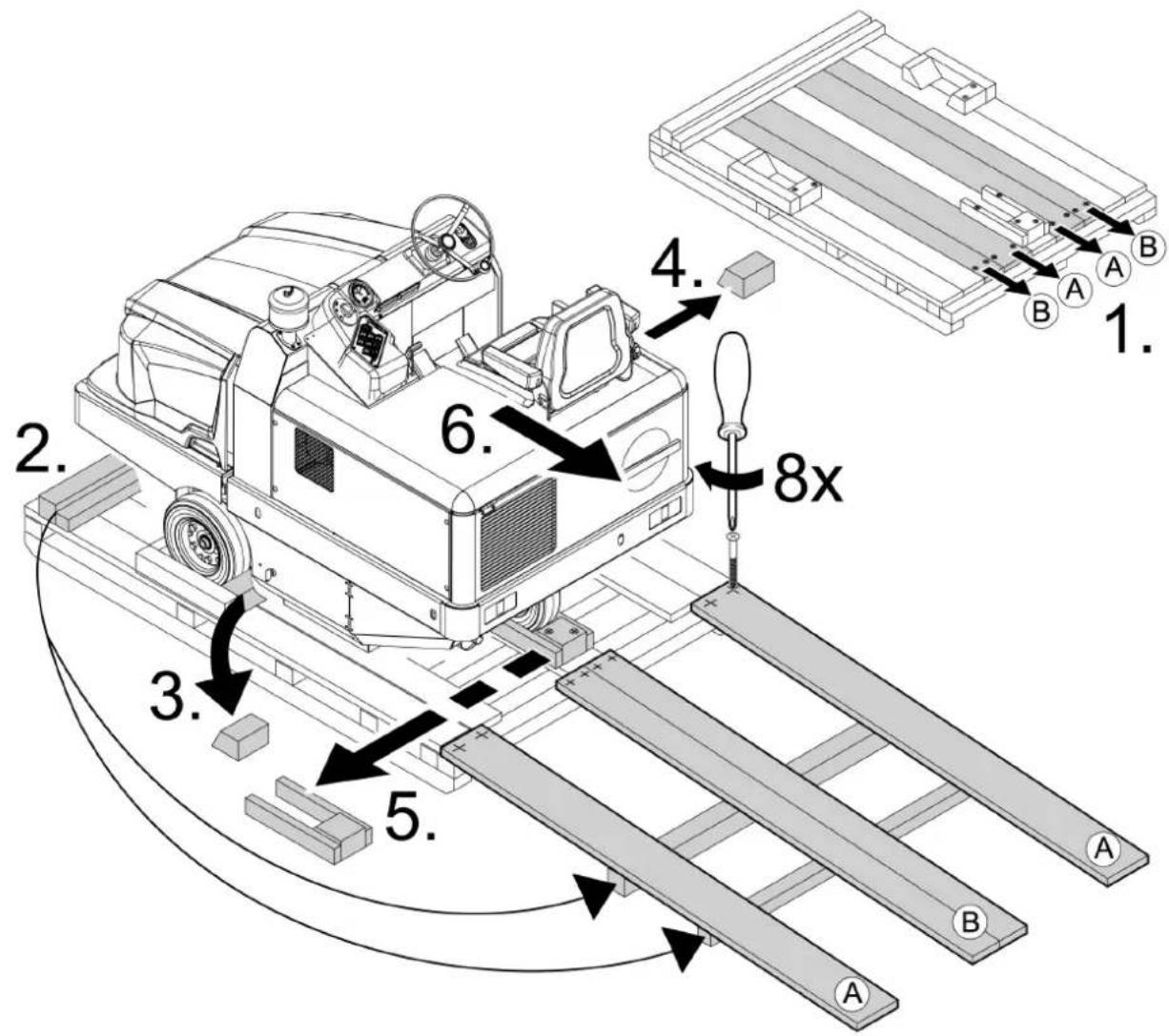
Unloading instructions
△DANGER
Risk of accident when unloading the machine
Use a suitable ramp when unloading the machine.
Do not use a forklift to unload/load the machine.
Be aware of the weight of the machine when unloading/loading.
Illustration A
- Use the enclosed boards to build a ramp according to the sketch.
- Cut the plastic packing strips and remove the film.
- Remove the strap fastening at the attachment points.
- Unscrew the marked floor boards and the squared timber on the pallet.
- Position the boards on the edge of the pallet; align the boards so that they lie in front on the wheels on the machine. Screw the boards tight.
- Place the squared timber under the boards as a support.
- Remove the wooden blocks locking the wheels.
- Release the parking brake.
- Carefully drive the machine off the pallet via the ramp provided, see Moving the sweeper with its own drive (device is ready to drive) or push it off the pallet, see Moving the sweeper without its own drive
Locking/releasing the parking brake
Locking
- Keep the brake pedal depressed and pull the brake lever.
Releasing - Keep the brake pedal depressed and release the brake lever.
Moving the sweeper without its own drive
Illustration J
①Freewheel screw
Illustration I
①Freewheel spanner
-
To push the device, loosen the freewheel screw. a Open the engine cover. b Loosen the freewheel screw with the freewheel spanner.
-
Release the parking brake.
-
Push the machine.
Note
Do not move the sweeper over long distances and not faster than 10 km/h without its own drive.
Note
Tighten the freewheel screw again after pushing.
Moving the sweeper with its own drive (device is ready to drive)
1 After pushing the device, tighten the freewheel screw.
a Apply the parking brake.
b Tighten the freewheel screw with the freewheel spanner.
c Close the cover and the bonnet.
Initial startup
Safety instructions for initial startup
Please read the operating instructions of the motor manufacturer and be sure to observe the safety instructions before the initial startup.
Fitting/replacing a gas cylinder
△DANGER
Risk of injury
There is a risk of injury and death when handling gas cylinders.
Observe the safety guidelines for liquid gas vehicles
Icing and foamy yellow deposits on the gas cylinder indicate leaks.
Cylinder replacement may only be carried out by trained personnel.
Propellant gas cylinders must not be replaced in closed rooms or in rooms below ground level.
Do not smoke or use an open light during cylinder replacement. During cylinder replacement, close the stop valve of the liquid gas cylinder tightly and put the protective cover on the empty cylinder immediately.
Only type-tested interchangeable cylinders with a capacity of 11 kg may be used.
ATTENTION
Material damage
The use of an incorrect gas mixture can lead to engine failure.
LPG mixtures of propane and butane are permitted. The propane content must be at least 90%.
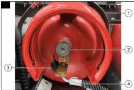
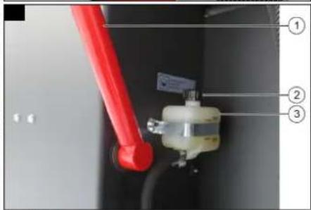
Illustration D
①Clip lock
②gas outlet valve
③ Protective cover
④Gas hose with union nut
1. Open the right cover.
2. Open the access to the gas cylinder.
3. Close the gas outlet valve by turning it clockwise.
4. Unscrew the gas hose by turning it clockwise (spanner size 30 mm).
5. Screw the protective cover onto the gas cylinder's connection valve.
6. Open the clip lock.
7. Replace the gas cylinder.
a Installation position: Connection (ring opening) must face downwards.
-
Unscrew the protective cover from the gas cylinder's connection valve.
-
Close the clip lock.
-
Screw the gas hose to the connection valve of the gas cylinder by turning it anti-clockwise (spanner size 30 mm).
11.Open the gas outlet valve by turning it anti-clockwise.
- Close the cover and access to the gas cylinder.
Operation
Work before starting operation
Note
For the procedures for the work listed, see Maintenance work
- Check the engine oil level.
- Check the filling level in the coolant expansion tank.
- Check the roller brush and side brushes for any tangled straps.
-
Check the wheel axles for wrapped straps.
-
Check the centrifugal separator and the air filter and clean if necessary.
- Test to ensure that the control elements are fully functional.
- Check the machine for damage.
- Dedust the dust filter.
Setting the driver's seat
△DANGER
Danger of accident
Only adjust the driver's seat when the device is standing.
Illustration S
① Weight setting
②Armrest height adjustment
③Backrest inclination adjustment
④ Seat position adjustment lever
- Adjust the suspension of the seat to your body weight by turning the adjustment knob.
- Adjust the height of the armrest by turning the mechanism underneath the armrest.
- Adjust the inclination of the backrest by turning the adjuster.
- Press the adjustment lever to release the latching mechanism and adjust the seat position to your height.
Starting the machine
Note
To start the machine, the engine cover must be closed and the operator must be seated.
Note
The sweeper is switched off 3 seconds after leaving the seat.
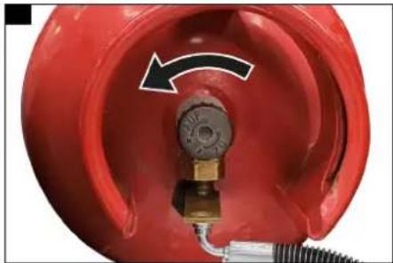
Illustration E
- Open the gas outlet valve by turning it anti-clockwise.
- Sit in the driver's seat.
The seat contact switch is actuated.
- Bring the travel direction selector switch to the middle position.
- Insert the ignition key in the ignition lock.
Note
Never leave the ignition key in position "II" for longer than 10 seconds. Wait for at least 10 seconds before trying again.
5. Start the engine
a Hold the brake pedal pressed.
b Turn the ignition key to the "I" position and hold for 3 seconds.
c Turn the ignition key to the "II" position.
The engine starts.
Driving the machine
⚠️DANGER
Risk of injury due to abrupt stopping!
The machine comes to an abrupt stop as soon as the driver's seat is not occupied.
Do not stand up from the driver's seat while driving.
△WARNING
Risk of accidents when reversing!
There is an increased risk of accidents when reversing.
Before reversing, make sure that you do not endanger anyone, pay particular attention to children. Have a person brief you if necessary.
When reversing, observe the entire surroundings.
△WARNING
Risk of accident when driving with raised waste container!
When driving with the waste container raised, there is an increased risk of accidents due to a change in the machine's centre of gravity.
Do not drive with the waste container raised.
ATTENTION
Risk of damage to the drive!
Jerky operation of the accelerator pedal can damage the drive.
Always operate the accelerator pedal slowly and carefully.
Bring the machine to a standstill before changing from forward to reverse or vice versa.
ATTENTION
Risk of damage
Driving over obstacles can cause damage to the machine. Drive over fixed obstacles up to 70 mm high slowly and carefully. Obstacles of more than 70 mm in height may only be driven over with a suitable ramp.
- Increase the engine speed by pressing the "high engine speed" buttons.
- Set the travel direction switch to the "Forward travel" or "Reverse travel" position.
- Take your foot off the brake pedal.
- Press the accelerator pedal carefully and adjust the travel speed continuously. Do not jerk the accelerator pedal.
- Steer the travel direction using the steering wheel.
- Release the accelerator pedal to reduce speed. The brake pedal can be depressed to increase the braking effect.
Sweeping mode
Sweeping with roller brush and side brush
△DANGER
Risk of injury due to abrupt stopping!
The machine comes to an abrupt stop as soon as the driver's seat is not occupied.
Do not stand up from the driver's seat while driving.
ATTENTION
Risk of damage by sweeping up tapes and cords!
If long, flexible objects such as e.g. tapes or cords are swept up, they can damage the sweeping mechanism.
Do not drive the machine or side brush over long, flexible objects such as e.g. tapes or cords and do not sweep up such objects.
Note
The travel speed must be adjusted to the circumstances in order to achieve optimum cleaning results.
Note
The dust filter is automatically cleaned every 10 minutes during sweeping. In the meantime, cleaning can be started manually.
Note
Switch on the blower when sweeping dry floors.
Switch off the blower when sweeping wet and damp floors to prevent the dust filter from getting wet.
-
Open the flap of the waste container before sweeping.
-
Lower the roller brush.
● To sweep side edges, also lower the side brushes.
Emptying the waste container
⚠ WARNING
Risk of injury from the machine tipping over
When emptying on slopes or on soft ground, the machine can tip due to the shift in the centre of gravity and injure people.
Only empty the waste container while the machine is on level, firm ground.
⚠ WARNING
Risk of injury due to impact and crushing
When lifting or lowering the waste container, people can be injured by being pushed or crushed between the waste container and the container
Make sure that no persons are in the swivel range of the waste container during the emptying process.
⚠ WARNING
Risk of injury due to moving machine parts
The mechanics of the waste container can crush or shear off body parts, especially fingers.
Do not touch moving parts during the emptying process.
△WARNING
Risk of injury if the waste container falls!
The raised waste container can fall abruptly and cause serious injuries due to crushing and trapping.
Do not walk underneath the waste container if it is unsecured. Secure the raised waste container properly with the supplied safety brace before walking underneath the waste container.
ATTENTION
Risk of injury due to waste being flung about
The roller brush that is running during the emptying process can throw waste away from itself, which can cause injuries.
Ensure that there are no persons in front of the vehicle when the waste container is raised.
Note
With the machine's high-level emptying, the waste container can be emptied into e.g.a waste container (maximum unloading height, see chapter Technical data).
- Position the machine in front of the unloading point.
ATTENTION
Ensure sufficient clearance behind and above the waste container.
Raising:
-
Set the control lever "Lift/Lower side brushes" to "Lift" and hold until the side brushes are fully lifted.
-
Set the control lever "Lift/Lower roller brush" to "Lift" and hold until the roller brush is fully lifted. The roller brush is lifted.
-
Set the "Open/Close container flap" control lever to "Close". The indicator light lights up red.
Emptying:
-
Set the control lever "Lift/Lower waste container" to "Lift" and keep it pulled until the required height is reached. The indicator light lights up red.
-
Slowly drive up to the container.
-
Apply the parking brake.
-
Set the "Open/Close container flap" control lever to "Open". The waste container is emptied. Indicator light lights up green.
-
Set the "Open/Close container flap" control lever to "Close". The container flap is closed. The indicator light lights up red.
-
Release the parking brake.
Lowering:
- Move the machine approx. 2 m away from the unloading point.
ATTENTION
Ensure sufficient clearance behind and under the waste container.
- Set the control lever "Lift/Lower waste container" to "Lower" and keep it pulled until the waste container has reached the end position. Indicator light lights up green.
Switching off the machine
-
Park the machine on a horizontal surface.
-
Raise the roller brush and side brushes.
-
Close the container flap.
-
Keep the brake pedal depressed and lock the parking brake.
-
Turn the key-operated switch to "0" and remove the key.
Illustration F
- Close the gas outlet valve by turning it clockwise.
Transport
ATTENTION
Transport damage
Observe the machine's net weight (transport weight) when transporting it on trailers or vehicles.
When transporting in vehicles, secure the device against slipping and tipping over according to the applicable guidelines.
⚠ WARNING
Danger from escaping gas
When transporting the machine, jolting and jerky movements can loosen connections of gas-carrying components and cause gas to escape.
Before each transport, ensure that the gas outlet valve on the gas cylinder is closed.
Observe the following when transporting the machine:
- Turn the ignition key to "0" and remove the key.
- Apply the parking brake.
- Secure the machine at the lashing points (4x) with tension belts, ropes or chains.
- Secure the machine to the wheels with wedges.
- Disconnect the battery.
Storage
Observe the following when storing the machine:
- Park the sweeper on a level surface in a dry, frost-free environment. Protect against dust with a tarp.
- Lift the roller brush and side brushes to avoid damaging the bristles.
- Close the container flap.
- Turn the ignition key to "0" and remove the key.
- Apply the parking brake.
- Secure the sweeper against rolling away.
- Close the gas outlet valve on the gas cylinder.
- Have the machine, in particular the liquid gas cylinder and its connections, inspected by a qualified person at regular intervals in accordance with national regulations.
If the sweeper is not used for a long time, also perform the following:
- Change the engine oil
- Remove the gas cylinder and store it upright in a suitable area.
- During frost maintenance, drain the cooling water or check whether it contains sufficient antifreeze.
- Clean the inside and outside of the sweeper.
- Disconnect the battery
- Charge the battery and recharge it approx. every 2 months.
Care and maintenance
⚠ WARNING
Danger to life, risk of injury and damage!
During care and maintenance of the machine, there is a danger to life, and risk of injury and damage if the safety instructions are not observed!
Adhere to the safety instructions for care and maintenance in the Safety instructions chapter at the beginning of these operating instructions.
Cleaning the device
ATTENTION
Short-circuits or other damage. Do not clean the device with a hose or high-pressure water jet.
ATTENTION
Improper cleaning
Risk of damage.
Do not use any abrasive or aggressive detergents.
△DANGER
Health risk from dust
For interior cleaning with compressed air.
Wear a dust mask and safety goggles.
Cleaning the interior of the machine
- Switch off the machine, see Switching off the machine
- Clean the machine with a cloth
- Blow out the machine with compressed air.
Cleaning the exterior of the machine
- Switch off the machine, see Switching off the machine.
- Clean the exterior of the machine with a cloth moistened with mild washing lye.
Maintenance intervals
Note
To preserve eligibility for warranty claims, all servicing and maintenance work during the warranty period has to be performed by an authorised service department, in accordance with the inspection checklist (ICL).
- The operating hour counter indicates the time of the maintenance intervals.
- The intervals for service and maintenance work by the customer/operator are listed in the chapter Maintenance by the customer. The work must be carried out by qualified staff. If necessary, consult a Kärcher specialist dealer or service department.
- Further maintenance work must be carried out by the authorised service department according to the inspection checklist. Please contact the service department in good time.
Maintenance by the customer
Note
The following maintenance work must be carried out by a qualified specialist. Consult a Kärcher specialist dealer or Service provider if necessary.
Work on the hydraulics may only be carried out by the authorized Service provider.
Daily:
- Check the engine oil level.
- Check the filling level in the coolant expansion tank.
- Check the centrifugal separator and clean if necessary.
- Check air filter and clean if required
- Check the wheel axles for wrapped straps.
- Check the roller brush and side brushes for wear and any tangled straps.
- Check that the control elements are fully functional.
- Check the machine for damage.
Weekly:
△WARNING
Risk of injury if the waste container falls!
The raised waste container can fall abruptly and cause serious injuries due to crushing and trapping.
Do not walk underneath the waste container if it is unsecured. Secure the raised waste container properly with the supplied safety brace before walking underneath the waste container.
- Check all moving parts for ease of motion and have them lubricated or repaired if necessary.
Note
Before all service and repair work with the waste container raised, install the safety brace.
-
Check the gas pipework system for leaks.
-
Check the sealing strips on the roller brush box for correct adjustment and wear, if necessary correct the adjustment and replace worn sealing strips.
- Check the sealing strips on the waste container flap for damage, replace if necessary.
- Check the roller brush for wear and tear and replace if necessary.
- Check the side brushes for wear and tear, replace if necessary.
- Check the dust filter for dirt and damage, replace if necessary and clean the dust filter box.
- Check the hydraulic system for leaks and have it repaired if necessary.
- Clean the hydraulic oil cooler.
- Check the hydraulic oil level.
- Clean the water cooler.
- Check the brake fluid level.
- Check the mechanics of the container flap and lubricate if necessary.
After wear and tear:
-
Replace the worn out sealing strips.
-
Replace the worn out roller brush.
-
Replacing the worn out side brushes.
Maintenance by Customer Service
Note
In order to preserve warranty claims, all servicing and maintenance work during the warranty period has to be performed by an authorised Kärcher Customer Service, in accordance with the inspection check list.
- Initial inspection after 50 operating hours
- Maintenance after 250 / 500 / 1000 / 1500 / 2000 operating hours
Maintenance work
Preparation
- Place the sweeper on a level surface.
- Turn the ignition lock to "0" and remove the key.
- Apply the parking brake.
- Close the gas outlet valve by turning it clockwise.
Safety instructions for maintenance
Note
Used oil and fluids such as diesel and engine oil that escape during maintenance work are a burden on the environment. Only have used oil disposed of by a specialised company and dispose of leaking fluids in an environmentally friendly manner.
Note
Before carrying out work under the raised waste container, the waist container must be secured against falling, see Securing the waste container
Securing the waste container
⚠ WARNING
Danger of crushing
A falling waste container can cause crushing injuries and broken bones.
Before carrying out any work under the raised waste container, it must be secured.
Only fit the locking rod from outside the hazard zone.
Illustration W
①Mount
②Locking rod
- Fold up the safety bar and insert it into the holder.
Removing the gas cylinder holder
△DANGER
Risk of injury
There is a risk of injury and death when handling gas cylinders.
Observe the safety guidelines for liquid gas vehicles
Icing and foamy yellow deposits on the gas cylinder indicate leaks.
The gas cylinder may only be removed by trained personnel.
Propellant gas cylinders must not be removed in closed rooms or in rooms below ground level.
Do not smoke or use an open light when removing the gas cylinder.
When removing the gas cylinder, close the stop valve of the liquid gas cylinder tightly and place the protective cover on the cylinder immediately.
Illustration D
①Clip lock
②Gas outlet valve
③Protective cover
④Gas hose with union nut
-
Open the right cover.
-
Open the access to the gas cylinder.
-
Close the gas outlet valve by turning it clockwise.
-
Unscrew the gas hose by turning it clockwise (spanner size 30 mm).
- Screw the protective cover onto the gas cylinder's connection valve.
- Open the clip lock.
- Remove the gas cylinder.
Illustration N
①Screw
②Gas cylinder holder
- Unscrew the screw.
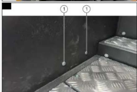
Illustration M
①Screw
-
Unscrew the screws in the foot area.
-
Remove the gas cylinder holder. The battery is now accessible.
-
Installation is performed in reverse sequence. a Installation position of the gas cylinder: Connection (ring opening) must face downwards.
Installing and connecting the battery
As standard, the machine is equipped with a maintenance-free battery.
- Remove the gas cylinder holder, see Removing the gas cylinder holder.
Illustration G
① Positive terminal
②Terminal cover
③Negative terminal
-
Fit the battery into the battery holder.
-
Screw the support on the battery base tight
-
Connect the terminal connection (cable with red terminal cover) to the positive terminal.
-
Connect the terminal connection (cable with black terminal cover) to the negative terminal.
-
Fit the terminal covers.
-
Check that the battery terminals and terminal clamps are sufficiently protected with terminal grease.
-
Attach the battery cover.
Removing the battery
- Remove the gas cylinder holder, see Removing the gas cylinder holder.
- Remove the battery cover.
- Remove the terminal covers from the negative and positive terminals.
- Disconnect the terminal connection from the negative terminal.
- Disconnect the terminal connection from the positive terminal.
- Remove the brackets from the battery base.
- Take the battery out of the battery holder.
- Dispose of the faulty batteries in accordance with statutory provisions.
Charging the battery
⚠ WARNING
Risk of injury
Observe the safety instructions on the handling of batteries.
Follow the operating instructions of the charger manufacturer.
△CAUTION
Risk of damage
An improper charging process can render the battery unusable. Only charge the battery with the appropriate charger.
- Unscrew all cell caps (only with low-maintenance battery).
- Connect the plus cable of the charger to the plus terminal of the battery.
-
Connect the negative cable of the charger to the negative terminal of the battery.
-
Plug in the mains plug and switch on the charger.
a Charge the battery with as low a charging current as possible. - When the battery is fully charged, first disconnect the charger from the mains supply and then from the battery.
- Screw in the cell caps. (Only for low-maintenance battery)
Checking brake fluid level and topping up
⚠ WARNING
Danger of crushing
A falling waste container can cause crushing injuries and broken bones.
Before carrying out any work under the raised waste container, it must be secured.
Only fit the locking rod from outside the hazard zone.
Illustration H
①Locking rod
②Cap
③Brake fluid reservoir
-
Move the waste container upwards and secure it with the safety bar.
-
Check whether there is sufficient brake fluid in the brake fluid reservoir.
Note
The filling level must lie between Min. and Max.
3. Top up with DOT brake fluid if necessary, see Technical data.
Checking the engine oil level and topping up the oil △CAUTION
Danger of burns
Hot engine parts can cause skin burns.
Allow the engine to cool down before carrying out the work.
Illustration R
①Oil filler cap
②Oil dipstick
-
Pull out the oil dipstick.
-
Wipe the dipstick with a cloth and insert it into the dipstick socket.
- Pull out the oil dipstick.
- Read off the oil level on the oil dipstick
a The oil level must lie between the "MIN" and "MAX" markings.
b Top up with engine oil if the oil level lies below the "MIN" marking.
- Insert the dipstick into the measuring socket.
- Remove the oil filler cap.
- Fill the engine oil into the oil filler neck.
a For oil type refer to technical specifications
b Do not fill the engine above the "MAX" marking.
- Close the oil filler neck with the oil filler cap.
-
Wait five minutes.
-
Check the engine oil level again.
Changing the engine oil and engine oil filter
△CAUTION
Danger of burns
Hot engine oil can burn the skin.
Allow the engine to cool down before carrying out the work.
Illustration Z
①Oil drain screw
- Provide a catch pan for at least 6 litres of engine oil.
- Remove the oil filler cap.
- Position the catch pan under the oil drain plug.
- Unscrew the oil drain plug.
- Wait until no more oil leaks.
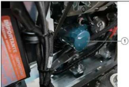
Illustration Y
①Oil filter
6. Unscrew the oil filter.
- Cleaning the mounting and sealing surfaces on the engine
- Prior to installation, coat the seal of the new oil filter with oil.
- Screw in the new oil filter and hand-tighten.
- Screw in the oil drain screw with a new seal. (Tightening torque: 25 Nm)
- Fill the engine oil into the oil filler neck. (Refer to the "Technical data" for the filling quantity and type.
- Close the oil filler neck with the oil filler cap.
- Allow the engine to run for approx. 10 seconds.
- Check the engine oil level.
Checking the hydraulic oil level and topping up the hydraulic oil
Illustration L
① Sealing cap and oil filler neck
②Oil sight glass
Note
The waste container must not be raised when carrying out this work.
- Check the hydraulic oil level in the oil sight glass.
a The oil level must lie between the "MIN" and "MAX" markings.
b Top up with hydraulic oil if the oil level lies below the "MIN" marking. - Remove the oil filler cap.
- Clean the filling area.
- Top up the hydraulic oil. (For oil type, refer to technical specifications)
- Close the oil filler neck with the cap.
Checking the hydraulic system
Note
If leaks are detected in the hydraulic system, contact Customer Service.
- Apply the parking brake.
- Start the motor.
- Check all hydraulic hoses and connections for leaks.
Check the coolant level
Illustration O
①Coolant expansion tank
Note
The engine must be cold for the filling level to be displayed correctly.
- Read the filling level on the coolant expansion tank.
a The filling level must lie between the Min. and Max markings.
Checking and cleaning the coolant/hydraulic oil cooler
△CAUTION
Danger of burns
Hot engine parts can cause skin burns.
Allow the engine to cool down before carrying out the work.
- The coolant level from the radiator is checked at the coolant expansion tank. See Check the coolant level
- Clean the radiator fins. Remove dirt using a soft brush, compressed air, or low water pressure.
- Check the hydraulic hoses and connections for leaks.
- Clean the fan.
Checking the roller brush for entangled pieces of tape
- Start the motor.
- Raise the waste container to the end position.
- Shut down the engine.
- Apply the parking brake.
⚠ WARNING
Danger of crushing
A falling waste container can cause crushing injuries and broken bones.
Before carrying out any work under the raised waste container, it must be secured.
Only fit the locking rod from outside the hazard zone.
-
Secure the waste container with the safety bar.
-
Check the roller brush for rolled-up straps and cords and remove them.
-
Fold in the safety bar.
-
Start the motor.
-
Lower the waste container to the end position.
10.Shut down the engine.
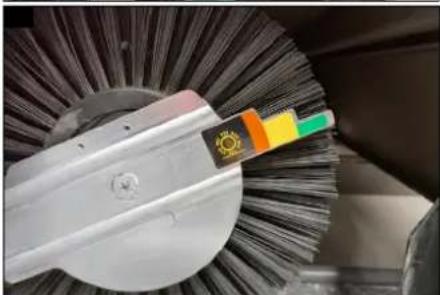
Checking the roller brush for wear
-
Unlock the door to the roller brush.
-
Pivot the door outwards.
Illustration AC
- Read off the degree of wear on the roller brush from the scale.
- If the degree of wear is at the end of the red zone, a new roller brush must be installed.
Replacing the roller brush
Illustration AB
①Door
②Handle screw
③Brush roller mount
④Roller brush
1. Unlock the door.
2. Pivot the door outwards.
3. Release the handle screw.
4. Pivot the roller brush mount outwards.
5. Remove the roller brush.
6. Install the new roller brush.
a Insert the roller brush into the opposite roller brush mount in the correct installation position.
Illustration AG
Installation position of the roller brush in the direction of travel (top view)
Note
The grooves of the roller brush must be fitted onto the cams of the opposite roller brush mount.
b Pivot the roller brush mount, which was swung out, back in. c Tighten the handle screw.
- Swing back the door.
- Lock the door.
Note
After installing the new roller brush, the sweeping pattern must be readjusted.
Check and adjust the sweeping pattern of the roller brush
- Switch off the blower.
- Drive the sweeper onto a flat, smooth surface that is visibly covered with dust or chalk.
- Lower the roller brush and let it run on the spot for approx. 10 seconds.
- Close the container flap.
- Raise the roller brush.
- Drive the machine away in reverse.
- Check the sweeping pattern.
Illustration AD
The sweeping pattern should be a uniform rectangle with a width of a = 60 - 65 mm.
Illustration AE
① Sweeping pattern lever
②Dial
- Depending on the degree of wear on the roller brush, engage the sweeping pattern lever in one of the 4 positions.
Check and adjust the sweeping pattern of the side brush
- Raise the side brushes.
- Drive the sweeper onto a flat, smooth surface that is visibly covered with dust or chalk.
- Lower the roller brush and the side brushes and let them run on the spot for approx. 10 seconds.
- Raise the roller brush and side brushes.
- Drive the machine away in reverse.
- Check the sweeping pattern.
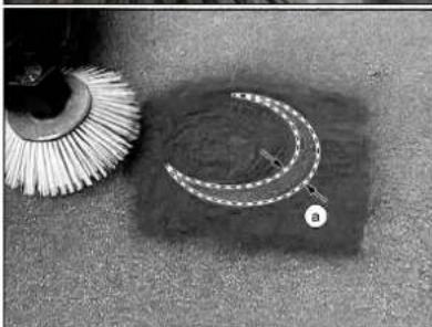
Illustration AF
The sweeping pattern should have a width of a = 40 - 50 mm and a moon-shaped partial circle between 11 and 4 o'clock.
Illustration AH
① Angle adjustment
②Length adjustment
-
Correct the sweeping pattern using the angle and length adjustment.
-
Correct the sweeping pattern using the angle and length adjustment.
-
Correct the sweeping pattern using the angle and length adjustment.
-
Correct the sweeping pattern using the angle and length adjustment.
-
Correct the sweeping pattern using the angle and length adjustment.
-
Correct the sweeping pattern using the angle and length adjustment.
Adjust the side seals
Illustration AI
①Door
②Seal
③Screw (8x)
④Retaining plate
- Unlock the door.
- Pivot the door outwards.
- Release the retaining plate by undoing the eight fastening screws.
- Realign the seal so that there is a 1 - 3 mm gap to the ground.
- Tighten the eight screws.
- Open the door on the opposite side.
Illustration AJ
①Retaining plate
②Wing nut (4x)
③Seal
- Loosen the retaining plate by loosening the four wing nuts.
- Realign the seal so that there is a 1 - 3 mm gap to the ground.
- Tighten the four wing nuts.
Cleaning the dust filter manually
- Press the "Clean dust filter" button.
The dust filter is cleaned.
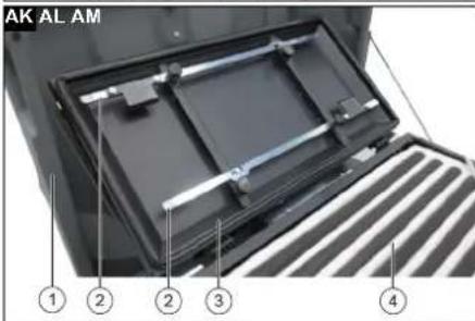
Replacing the dust filter (pocket filter)
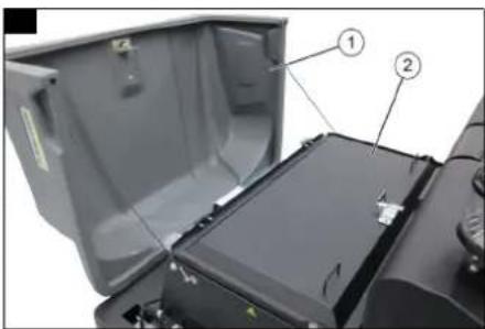
The waste container is emptied. See Emptying the waste container.
△CAUTION
Health hazard due to fine dust
Inhaling fine dust can lead to respiratory diseases.
Wear suitable mouth and nose protection when changing the dust filter.
Illustration AK
①Cover
②Lifting bar
③Filter cover
④ Pocket filter
- Open the cover.
- Open the filter cover.
- Detach the two lifting bars from the filter cover.
- Insert the two clamping plates on the lifting bars into the centre of the pocket filter as shown.
Illustration AL
①Handle screw
②Lifting bar
- When inserted, screw the two lifting bars together with the two handle screws.
- Lift out the pocket filter with two people.
- Remove the two lifting bars from the old pocket filter and attach them to the new pocket filter.
- Insert the new pocket filter with two people.
- Remove the two lifting bars from the new pocket filter.
- Fit the two lifting bars to the inside of the cover.
- Close the filter cover and lock it with the fasteners.
- Close the cover.
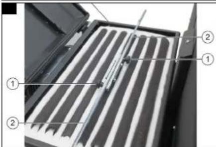
Replacing the dust filter (flat fold filter)
The waste container is emptied. See Emptying the waste container.
△CAUTION
Health hazard due to fine dust
Inhaling fine dust can lead to respiratory diseases. Wear suitable mouth and nose protection when changing the dust filter.
Illustration AM
①Cover
②Filter cover
③Cleaning fixture
-
Open the cover.
-
Open the filter cover.
Illustration AN
①Cleaning fixture
②Flat fold filter
-
Fold up the cleaning device.
-
Remove both flat fold filters.
-
Fit the new flat fold filters.
-
Fold down the cleaning device.
-
Close the filter cover and lock it with the fasteners.
-
Close the cover.
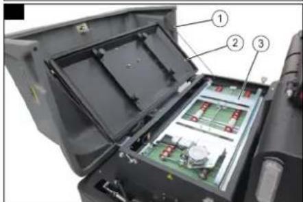
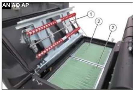
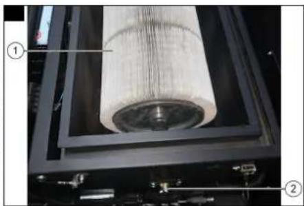
Replacing the dust filter (round filter)
The waste container is emptied. See Emptying the waste container.
△CAUTION
Health hazard due to fine dust
Inhaling fine dust can lead to respiratory diseases.
Wear suitable mouth and nose protection when changing the dust filter.
Illustration AO
①Cover
②Filter cover
-
Open the cover.
-
Open the filter cover.
Illustration AP
①Round filter
②Lock
- Release the lock.
a Pull out the lock completely.
b Turn clockwise until the lock engages.
- Remove the filter.
Note
When inserting the filter, ensure that the holes in the front of the filter are positioned on the bolts of the filter holder.
-
Insert a new filter and close the lock.
-
Close the filter cover and lock it with the fasteners.
-
Close the cover.
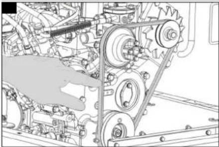
Checking the tension of the V-belt
Illustration AR
Note
If the V-belt cannot be pressed in as described, the V-belt tension must be adjusted by an authorised Customer Service agent.
- Using your thumbs, push in the V-belt between the belt pulleys.
You should be able to depress the V-belt by about 7 mm to 9 mm.
Cleaning the centrifugal separator
Illustration AS
①Wing nut
②Centrifugal separator
-
Unscrew the wing nut and remove the cover.
-
Clean the inside of the centrifugal separator.
-
Fit the cover and tighten the wing nut.
Replacing the fuses
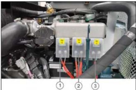
The main fuse (FU13), the alternator fuse (FU14) and the power relay fuse (FU15) are located in the engine compartment.
Illustration V
①Main fuse (FU13)
②Engine fuse (FU14)
③Fuse for the power relay (FU15)
The fuse holders are located underneath the steering wheel.
Illustration U
-
Remove the cover of the fuse holder.
-
Check the fuses and replace defective fuses.
Overview of fuses
| FU 01 Starter | 15 A | |
| FU 02 Magnet | coil 25 A | |
| FU 03 Fuel pump | 10 A | |
| FU 04 Multifunction display | 10 A | |
| FU 05 Vibrator | system and blower 25 A | |
| FU 06 Flashing | beacon, horn, blue spot 15 A | |
| FU 07 Indicator | (optional) 10 A | |
| FU 08 Indicator | (optional) 10 A | |
| FU 09 Lights, | left (optional) 7.5 A | |
| FU 10 Working light | 10 A | |
| FU 11 Lights, | right (optional) 7.5 A | |
| FU 12 Driver cabin | (optional), dust suppressor (optional) | 15 A |
| FU 13 Main fuse | 60 A | |
| FU 14 Motor | 60 A |
Troubleshooting guide
You can remedy minor faults using the following overview. Contact the Customer Service department in the case of any faults not listed!
△DANGER
Risk of accidents and injuries due to unintentional movement of the vehicle
Switch off the vehicle before carrying out any care and maintenance work, and remove the ignition key.
△DANGER
Risk of electric shock
Disconnect the battery when working on electrical components. Repair work and work on electrical components must only be performed by your authorised Customer Service.
| Fault Rectification | |
| Motor will not start | ● Sit in the driver's seat (the seat contact switch is activated)● Check/charge the starter battery● Gas cylinder empty, change gas cylinder● Gas outlet valve closed, open valve by turning anti-clockwise● Gas valve iced up, follow the description for replacing the gas cylinder.● Contact Kärcher Customer Service |
| Motor running irregularly | ● Clean the air filter or replace the filter cartridge● Check fuel lines, connections and joints and repair if necessary● Contact Kärcher Customer Service |
| ● Add coolant● Flush the radiator● Tension V-belt● Contact Kärcher Customer Service | |
| Engine runs, but the vehicle drives slow or not at all. | ● Release the parking brake● Set a high engine speed● Check the wheels for any wrapped straps or cords● Check the freewheel screw● Contact Kärcher Customer Service |
| Whistling sound in the hydraulic system | ● Topping up hydraulic oil● Contact Kärcher Customer Service |
| The roller brush / side brushes are not rotating | ● Set engine speed adjustment to operating speed● Check the roller brush / side brushes for any tangled straps or cords.● Contact Kärcher Customer Service |
| Low or no suction power in the brush area | ● Check, clean or replace the dust filter● Contact Kärcher Customer Service |
| Machine generates dust ● Adjust the side seals● Switch on the blower● Check, clean or replace the dust filter● Replace the filter seals● Open the waste container flap.● Contact Kärcher Customer Service | |
| Waste remains on the ground | ● Emptying the waste container● Check, clean or replace the dust filter● Replace the roller brush● Adjusting the sweeping pattern● Replace the sealing strip of the waste container● Remove the roller brush blockage● Open the waste container flap.● Contact Kärcher Customer Service |
| Waste container cannot be raised or lowered | ● Check the fuses● Contact Kärcher Customer Service |
| Container flap of waste container cannot be opened | ● Contact Kärcher Customer Service |
| Malfunctions in hydraulically moved parts | ● Contact Kärcher Customer Service |
Warranty
The warranty conditions issued by our relevant sales company apply in all countries. We shall remedy possible malfunctions on your appliance within the warranty period free of cost, provided that a material or manufacturing flaw is the cause. In a warranty case, please contact your dealer (with the purchase receipt) or the next authorised customer service site.
(See overleaf for the address)
Further warranty information (if available) can be found in the service area of your local Kärcher website under "Downloads".
EU Declaration of Conformity
We hereby declare that the product named below complies with the relevant provisions of the directives and regulations listed.
This declaration is invalidated by any changes made to the product that are not approved by us.
Product: Sweeper vacuum ride-on machine
Type: 1.186-xxx
Directives and Regulations
2006/42/EC (+2009/127/EC)
2000/14/EC
2014/30/EU
2014/53/EU (TCU)
Harmonised standards used
EN 60335-1
EN 60335-2-72
EN 62233: 2008
EN 55012: 2007 + A1: 2009
EN 61000-6-2: 2005
TCU
EN 300 328 V2.2.2
EN 300 330 V2.1.1
EN 300 440 V2.1.1
EN 301 511 V12.5.1
Applied conformity evaluation method
2000/14/EG: Annex V
Sound power level dB(A)
KM 170/600 R D
Measured: 100
Guaranteed: 103
KM 100/65 R Bp
Measured: 85
Guaranteed: 88
KM 105/180 R Bp
Measured: 87
Guaranteed: 90
KM 120/250 R D, KM 120/250 R BAT,
KM 120/250 R LPG
Measured: D: 97 BAT: 88 LPG: 101
Guaranteed: D: 99 BAT: 90 LPG: 104
KM 130/300 R D, KM 130/300 R LPG,
KM 130/300 R Bp (Bp Pack),
KM 130/300 R I D, KM 130/300 R I LPG,
Measured: D: 96 LPG: 98 Bp: 90
Guaranteed: D: 98 LPG: 101 Bp: 93
Measured: D: 99 LPG: 96
Guaranteed: D: 102 LPG: 99
KM 150/500 R Bp
Measured: 94
Guaranteed: 96
Name and address
Documentation supervisor:
S. Reiser
Alfred Kärcher SE & Co. KG
Alfred-Kärcher-Str. 28 - 40
71364 Winnenden (Germany)
Tel.: +49 7195 14-0
Fax: +49 7195 14-2212

H. Jenner
Chairman of the Board of Management

S. Reiser
Manager Regulatory Affairs & Certification
The undersigned act on behalf of and with the authority of the Board of Directors.
Winnenden, 2021/05/01
Alfred Kärcher SE & Co. KG
Alfred-Kärcher-Str. 28 - 40
71364 Winnenden (Germany)
Ph.: +49 7195 14-0
Fax: +49 7195 14-2212
Technical data
| KM 130/300 R I LPG | ||
| Device performance data | ||
| Travel speed, forwards km/h 10 | ||
| Travel speed, backwards km/h 10 | ||
| Climbing ability (max.) % 18 | ||
| Lateral inclination (max.) % 10 | ||
| Working width without side brushes mm 1000 | ||
| Working width with 1 side brushes mm 1300 | ||
| Working width with 2 side brushes mm 1550 | ||
| turning circle m 2,8 | ||
| Protection Class IPX 3 | ||
| Theoretical surface performance | ||
| Surface performance without side brushes m | ^2/h | 10000 |
| Surface performance with 1 side brushes | m^2/h | 13000 |
| Surface performance with 2 side brushes | m^2/h | 15500 |
| Battery | ||
| Battery capacity | Ah | 60 |
| Working voltage of the battery | V | 12 |
| Environmental conditions | ||
| Ambient temperature | °C | -5 ... +40 |
| Humidity, non-condensing | % 0 ... 90 | |
KM 130/300 R I LPG
| Dimensions and weights | ||
| Length mm 2040 | ||
| Width mm 1330 | ||
| Height mm 1430 | ||
| Net weight kg 920 | ||
| Approved total weight kg 1530 | ||
| Maximum permissible front axle load kg 902 | ||
| Maximum permissible rear axle load kg 628 | ||
| Width of roller brush mm 1000 | ||
| Diameter of roller brush mm 300 | ||
| Diameter of side brush mm 600 | ||
| Waste container | ||
| Waste container volume l 300 | ||
| Discharge height (max.) | mm 1400 | |
| Filter and suction system | ||
| Filter system | Bag filter | |
| Filter area of dust filter | m^2 | 7,8 |
| Usage category | U | |
| Suction system nominal volumetric flow | l/s | 222 |
| Blower and roller brush motor (electric) | ||
| Engine type | Permanent magnet DC motor | |
| Internal combustion engine | ||
| Engine type | Kubota WG 972-E4 | |
| Type | 3-cylinder four-stroke gas engine | |
| Engine capacity | cm^3 | 962 |
| CO2 emission according to the measurement procedure of EU regulation 2016/1628 (level V) | g/kWh | 1018,2 |
| Cooling type | Water cooling | |
| Engine performance | kW/PS | 17,5 / 23.5 |
| Fuel tank capacity | l | 11 kg / 20 l (Exchangeable bottle) |
| Operating materials | ||
| Fuel type | LPG | |
| Engine oil volume | l | 3,7 |
| Engine oil type if exterior temperatures is above 25 °C | SAE 30, SAE 10W-30, SAE 15W-40 | |
| Engine oil type if exterior temperatures is below 0 °C | SAE 20, SAE 10W-30, SAE 10W-40 | |
| Engine oil type if exterior temperatures is below 0 °C | SAE 10W, SAE 10W-30, SAE 10W-40 | |
| Oil volume l 3,5 | ||
| Type of hydraulic oil | HV 46 | |
| Hydraulic oil quantity | l | 26,5 |
| Tyres | ||
| Tyre size, front | mm 15-4.5x8 | |
| Tyre size, rear | 15-4.5x8 | |
| Brake | ||
| Brake fluid | Ate DOT SL - US FMVSS DOT4 | |
| Determined values according to EN 60335-2-72 | ||
| Hand-Arm Vibration value | m/s^2 | 1,5 |
| Hand-arm vibration value, uncertainty K | m/s^2 | 0,2 |
| Seat Vibration value m/s | ^2 | 0,8 |
| Seat vibration value, uncertainty K | m/s^2 | 0,2 |
| Sound pressure level L_pA | dB(A) | 80 |
| Uncertainty K_pA | dB(A) | 3 |
| Sound power level L_WA + uncertainty L_WA | dB(A) | 101 |
Subject to technical changes without notice.
Contenu
Attention aux brosses rotatives.
2006/42/CE (+2009/127/CE)
2000/14/CE
2014/30/UE
2014/53/EU (TCU)
71364 Winnenden (Germany)
71364 Winnenden (Germany)

H. Jenner
Chairman of the Board of Management

S. Reiser
Manager Regulatory Affairs & Certification
71364 Winnenden (Germania)
Tel.: +49 7195 14-0
Fax: +49 7195 14-2212

H. Jenner
Chairman of the Board of Management

S. Reiser
Manager Regulatory Affairs & Certification
Winnenden, 01/05/2021
Alfred Kärcher SE & Co. KG
Alfred-Kärcher-Str. 28 - 40
71364 Winnenden (Germany)
Tel.: +49 7195 14-0
Fax: +49 7195 14-2212
2006/42/CE (+2009/127/CE)
2000/14/CE
2014/30/UE
2014/53/UE (TCU)
71364 Winnenden (Germany)
Chairman of the Board of Management

S. Reiser
Manager Regulatory Affairs & Certification
Winnenden, 01/05/2021
Alfred Kärcher SE & Co. KG
Alfred-Kärcher-Str. 28 - 40
71364 Winnenden (Germany)
Tel.: +49 7195 14-0
Fax: +49 7195 14-2212
Datos técnicos
Regular as juntas laterais
Figura AI
2006/42/CE (+2009/127/CE)
2000/14/CE
2014/30/UE
2014/53/UE (TCU)
71364 Winnenden (Germany)
Telephone: +49 7195 14-0
Fax: +49 7195 14-2212

H. Jenner
Chairman of the Board of Management

S. Reiser
Manager Regulatory Affairs & Certification
Winnenden, 01/05/2021
Alfred Kärcher SE & Co. KG
Alfred-Kärcher-Str. 28 - 40
71364 Winnenden (Germany)
Tel.: +49 7195 14-0
Fax: +49 7195 14-2212

H. Jenner
Chairman of the Board of Management

S. Reiser
Manager Regulatory Affairs & Certification
Winnenden, 2021/05/01
Alfred Kärcher SE & Co. KG
Alfred-Kärcher-Str. 28 - 40
71364 Winnenden (Germany)
Tel.: +49 7195 14-0
Fax: +49 7195 14-2212
Technische gegevens
2006/42/AT (+2009/127/AT)
2000/14/AT
2014/30/AB
2014/53/EU (TCU)
Chairman of the Board of Management

S. Reiser
Manager Regulatory Affairs & Certification
Winnenden, 2021/05/01
Alfred Kärcher SE & Co. KG
Alfred-Kärcher-Str. 28 - 40
71364 Winnenden (Almanya)
Tel.: +49 7195 14-0
71364 Winnenden (Germany)
Telefon: +49 7195 14-0
Fax: +49 7195 14-2212

Chairman of the Board of Management

S. Reiser
Manager Regulatory Affairs & Certification
Winnenden, 01.05.2021
Alfred Kärcher SE & Co. KG
Alfred-Kärcher-Str. 28 - 40
D-71364 Winnenden (Germany)
Tfn: +49 7195 14-0
Fax: +49 7195 14-2212
Tekniska data
71364 Winnenden (Germany)
Puhelin: +49 7195 14-0
Chairman of the Board of Management

S. Reiser
Manager Regulatory Affairs & Certification
71364 Winnenden (Germany)
Puh.: +49 7195 14-0
Egnet belegg for feiing
- Asfalt
- Industrigulv
- Støpte gulv
- Betong
- Brostein
Skift støvfilteret (posefilter)
Feieavfallsbeholderen er tømt. Se Tøm feieavfallsbeholderen.
△FORSIKTIG
Skift støvfilteret (flatt foldefilter)
Feieavfallsbeholderen er tømt. Se Tøm feieavfallsbeholderen.
△FORSIKTIG
2006/42/EF (+2009/127/EF)
2000/14/EF
2014/30/EU
2014/53/EU (TCU)
Anvendte harmoniserte standarder
EN 60335-1
EN 60335-2-72
EN 62233: 2008
EN 55012: 2007 + A1: 2009
EN 61000-6-2: 2005
TCU
EN 300 328 V2.2.2
EN 300 330 V2.1.1
EN 300 440 V2.1.1
EN 301 511 V12.5.1
2000/14/EF: Vedlegg V
Lydeffektnivå dB(A)
KM 170/600 R D
Målt: 100
Garantert: 103
KM 100/65 R Bp
Målt: 85
Garantert: 88
KM 105/180 R Bp
Målt: 87
Garantert: 90
KM 120/250 R D, KM 120/250 R BAT,
KM 120/250 R LPG
Målt: D: 97 BAT: 88 LPG: 101
Garantert: D: 99 BAT: 90 LPG: 104
KM 130/300 R D, KM 130/300 R LPG,
KM 130/300 R Bp (Bp Pack),
KM 130/300 R I D, KM 130/300 R I LPG,
Garantert: D: 102 LPG: 99
KM 150/500 R Bp
Målt: 94
Garantert: 96
Navn og adresse
71364 Winnenden (Germany)
Telefon: +49 7195 14-0
Chairman of the Board of Management

S. Reiser
Manager Regulatory Affairs & Certification
Winnenden, 2021/05/01
Alfred Kärcher SE & Co. KG
Alfred-Kärcher-Str. 28 - 40
71364 Winnenden (Germany)
Tlf.: +49 7195 14-0
2006/42/EF (+2009/127/EF)
2000/14/EF
2014/30/EU
2014/53/EU (TCU)
71364 Winnenden (Germany)
Telefon: +49 7195 14-0
Fax: +49 7195 14-2212
Winnenden, 2021/05/01
Alfred Kärcher SE & Co. KG
Alfred-Kärcher-Str. 28 - 40
71364 Winnenden (Germany)
Tlf.: +49 7195 14-0
Fax: +49 7195 14-2212

H. Jenner
Chairman of the Board of Management

S. Reiser
Manager Regulatory Affairs & Certification
Tekniske data
Ohutusjuhised
Ohuastmed
△OHT
- Viide vahetult ähvardavale ohule, mis vöib pöhjustada raskeid kehavigastusi vöi löppeda surmaga.
△HOIATUS
Gaasiballooni monteerimine / vahetamine
△OHT
Vigastusoht
2006/42/EÜ (+2009/127/EÜ)
2000/14/EÜ
2014/30/EL
2014/53/EL (TCU)
71364 Winnenden (Germany)
Tel: +49 7195 14-0
Chairman of the Board of Management

S. Reiser
Manager Regulatory Affairs & Certification
Winnenden, 2021/05/01
Alfred Kärcher SE & Co. KG
Alfred-Kärcher-Str. 28 - 40
71364 Winnenden (Germany)
Tel: +49 7195 14-0
Chairman of the Board of Management

S. Reiser
Manager Regulatory Affairs & Certification

H. Jenner
Chairman of the Board of Management

S. Reiser
Manager Regulatory Affairs & Certification
2006/42/WE (+2009/127/WE)
2000/14/WE
2014/30/UE
2014/53/EU (TCU)
71364 Winnenden (Germany)
Telefon: +49 7195 14-0

Chairman of the Board of Management

S. Reiser
Manager Regulatory Affairs & Certification
71364 Winnenden (Germany)
Tel.: +49 7195 14-0
Chairman of the Board of Management

S. Reiser
Manager Regulatory Affairs & Certification
Winnenden, 2021/05/01
Alfred Kärcher SE & Co. KG
Alfred-Kärcher-Str. 28 - 40
2006/42/ES (+2009/127/ES)
2000/14/ES
2014/30/EU
2014/53/EU (TCU)
Chairman of the Board of Management

S. Reiser
Manager Regulatory Affairs & Certification
Winnenden, 2021/05/01
Alfred Kärcher SE & Co. KG
Alfred-Kärcher-Str. 28 - 40
2006/42/ES (+2009/127/ES)
2000/14/ES
2014/30/EÚ
2014/53/EÚ (TCU)
71364 Winnenden (Germany)
Tel.: +49 7195 14-0
Fax: +49 7195 14-2212

H. Jenner
Chairman of the Board of Management

S. Reiser
Manager Regulatory Affairs & Certification
Winnenden, 01.05.2021
Alfred Kärcher SE & Co. KG
Alfred-Kärcher-Str. 28 - 40
71364 Winnenden (Germany)
Tel.: +49 7195 14-0
Fax: +49 7195 14-2212
Technické údaje
②Ploski nagubani filter
-
Zložite napravo za čiščenje.
-
Odstranite oba ploska nagubana filtra.
-
Vstavite nova ploska nagubana filtra.
-
Napravo za čiščenje zložite navzdol.
-
Zaprite pokrov filtra in ga zaklenite z natezalnimi zapirali.
-
Zaprite pokrov naprave.
2006/42/ES (+2009/127/ES)
2000/14/ES
2014/30/EU
2014/53/EU (TCU)
Chairman of the Board of Management

S. Reiser
Manager Regulatory Affairs & Certification
Podpisniki ravnajo po navodilih in s pooblastilom uprave.
Winnenden, 1. 5. 2021
Alfred Kärcher SE & Co. KG
Alfred-Kärcher-Str. 28 - 40
Negotovost K_pA dB(A) 3
| Raven moči hrupa L_WA + negotovost L_WA | dB(A) | 101 |
Măsurat: D: 99 LPG: 96
Garantat: D: 102 LPG: 99
KM 150/500 R Bp
Măsurat: 94
Garantat: 96
Numele și adresa
71364 Winnenden (Germania)
Telefon: +49 7195 14-0
Fax: +49 7195 14-2212

H. Jenner
Chairman of the Board of Management

S. Reiser
Manager Regulatory Affairs & Certification
Winnenden, 2021/05/01
Alfred Kärcher SE & Co. KG
Alfred-Kärcher-Str. 28 - 40
71364 Winnenden (Germania)
Tel.: +49 7195 14-0
Fax: +49 7195 14-2212
Date tehnice
KM 130/300 R I LPG
2006/42/EZ (+2009/127/EZ)
2000/14/EZ
2014/30/EU
2014/53/EU (TCU)
Primijenjene uskladene norme
EN 60335-1
EN 60335-2-72
EN 62233: 2008
EN 55012: 2007 + A1: 2009
EN 61000-6-2: 2005
TCU
EN 300 328 V2.2.2
EN 300 330 V2.1.1
EN 300 440 V2.1.1
EN 301 511 V12.5.1
71364 Winnenden (Germany)
Tel.: +49 7195 14-0

H. Jenner
Chairman of the Board of Management

S. Reiser
Manager Regulatory Affairs & Certification
Winnenden, 01.05.2021
Alfred Kärcher SE & Co. KG
Alfred-Kärcher-Str. 28 - 40
71364 Winnenden (Njemačka)
Tel.: +49 7195 14-0
Telefaks: +49 7195 14-2212
2006/42/EZ (+2009/127/EZ)
2000/14/EZ
2014/30/EU
2014/53/EU (TCU)
Primenjene harmonizovane norme
EN 60335-1
EN 60335-2-72
EN 62233: 2008
EN 55012: 2007 + A1: 2009
EN 61000-6-2: 2005
TCU
EN 300 328 V2.2.2
EN 300 330 V2.1.1
EN 300 440 V2.1.1
EN 301 511 V12.5.1
Chairman of the Board of Management

S. Reiser
Manager Regulatory Affairs & Certification
Potpisnici deluju po nalogu i uz punomoć upravnog odbora.
Winnenden, 2021/05/01
Alfred Kärcher SE & Co. KG
Alfred-Kärcher-Str. 28 - 40
71364 Winnenden (Germany)
Tel.: +49 7195 14-0
71364 Winnenden (Germany)
Tηλ.: +49 7195 14-0
Φαξ: +49 7195 14-2212

H. Jenner
Chairman of the Board of Management

S. Reiser
Manager Regulatory Affairs & Certification
Winnenden, 2021/05/01
Alfred Kärcher SE & Co. KG
Alfred-Kärcher-Str. 28 - 40
71364 Winnenden (Germany)
Tηλ.: +49 7195 14-0
Φαξ: +49 7195 14-2212
71364 Winnenden (Germany)
Тел.: +49 7195 14-0
Факс: +49 7195 14-2212

H. Jenner
Chairman of the Board of Management

S. Reiser
Manager Regulatory Affairs & Certification
71364 Winnenden (Germany)
Тел.: +49 7195 14-0
Факс: +49 7195 14-2212

Chairman of the Board of Management

S. Reiser
Manager Regulatory Affairs & Certification
71364 Winnenden (Germany)
Тел.: +49 7195 14-0
Факс: +49 7195 14-2212
Chairman of the Board of Management

S. Reiser
Manager Regulatory Affairs & Certification
Winnenden, 2021/05/01
Alfred Kärcher SE & Co. KG
Alfred-Kärcher-Str. 28 - 40
71364 Winnenden (Germany)

Chairman of the Board of Management

S. Reiser
Manager Regulatory Affairs & Certification
71364 Winnenden (Germany)
71364 Winnenden (Germany)
電話:-49 7195 14-0
Fax: +49 7195 14-2212

H. Jenner
Chairman of the Board of Management

S. Reiser
Manager Regulatory Affairs & Certification
71364 Winnenden (Germany)
電話番号:+49 7195 14-0
www.kacrcher.com/REACH
按规定使用
Chairman of the Board of Management

S. Reiser
Manager Regulatory Affairs & Certification
Winnenden, 2021/05/01
Alfred Kärcher SE & Co. KG
Alfred-Kärcher-Str. 28 - 40
71364 Winnenden (德国)
电话:-49 7195 14-0
传真:-49 7195 14-2212
技术数据
KM 130/300 R I LPG
设备性能
| 行驶速度,前进 km/h 10 |
| 后退行驶速度 km/h 10 |
| 爬坡能力(最大) % 18 |
| 侧向倾斜度(最大) % 10 |
ال Effective Management Department of the United States
اليانيات الفنية
- flight from the world. (emptying the country that I have to take a picture of the country). 2. To suit the world's purpose for the country. 3. To suit the world's purpose for the country. 4. The country is not a picture of the country. a
a-Omp Office: I'm doing it's a copy of the following:
b Burk according to the information of the information.
2.حل فرملة الشبيت.
- حرك الماكينة.
إرشاد
natural_image
Black thumbs-up icon on white background (no text or symbols)THANK YOU!
Register your product and benefit from many advantages.
www.kaercher.com/welcome


Rate your product and tell us your opinion.
natural_image
Icon showing a gear and wrench, no text or symbols presentwww.kaercher.com/dealersearch
Alfred Kärcher SE & Co. KG
Alfred-Kärcher-Str. 28-40
71364 Winnenden (Germany)