BWE 16-9 14 - Electric drill Flex - Free user manual and instructions
Find the device manual for free BWE 16-9 14 Flex in PDF.

| Product Type | Diamond core bit (electric drill) |
| Brand | Flex |
| Model | BWE 16-9 14 |
| Supply voltage | 220-240 V / 50-60 Hz |
| Input power | 1600 W |
| Output power | 950 W |
| No-load speed | 3500-9000 rpm |
| Tool holder | M14 (male thread) |
| Max. bit diameter | 14 mm (clamping flange) |
| Water connection | 1/2\" with shut-off valve, max. 6 bars |
| Weight | 3.0 kg |
| Sound pressure level | 85 dB(A) |
| Sound power level | 93 dB(A) |
| Vibrations (stone cutting) | 4.67 m/s² |
| Protection class | II (double insulation) |
| Safety device | Integrated PRCD circuit breaker |
| Intended use | Drilling holes in natural stone, concrete and similar materials with water supply |
| Included accessories | Wrench 17, splash guard |
| Maintenance | Regular cleaning with dry compressed air; replace brushes with original parts |
| Repairs | Only entrust to an authorized service center |
Frequently Asked Questions - BWE 16-9 14 Flex
User questions about BWE 16-9 14 Flex
0 question about this device. Answer the ones you know or ask your own.
Ask a new question about this device
Download the instructions for your Electric drill in PDF format for free! Find your manual BWE 16-9 14 - Flex and take your electronic device back in hand. On this page are published all the documents necessary for the use of your device. BWE 16-9 14 by Flex.
USER MANUAL BWE 16-9 14 Flex
natural_image
Illustration of a power tool with a cutting tool and connecting cable (no text or symbols)natural_image
Close-up of a car's front panel showing a grille and vent, with a directional arrow indicating left motion (no text or symbols)Symbols used in this manual ..... 12
Symbols on the product ..... 12
Important safety information ..... 12
Noise and vibration 14
Technical data 15
Overview 16
Instructions for use 17
Maintenance and care 19
Disposal information 19
C€ Declaration of Conformity ..... 19
UK CA Declaration of Conformity ..... 19
Exemption from liability 19
Symbols used in this manual

WARNING!
Denotes impending danger.
Non-observance of this warning may result in death or extremely severe injuries.

CAUTION!
Denotes a potentially dangerous situation.
Non-observance of this warning may result in injury or damage to property.

NOTE
Denotes application tips and important information.
Symbols on the product

Before switching on the power tool, read the operating manual!
Wear goggles!

Always operate with two hands!


Disposal information for the old tool (see page 19).

Protection class II

CE marking
Important safety information

WARNING!
Before using the power tool, please read the following and act accordingly:
– These operating instructions
- The "General safety instructions" on the handling of power tools in the enclosed booklet (leaflet no.: 315915)
– The currently valid site rules and the regulations for the prevention of accidents
This power tool is state of the art and has been assembled in accordance with the acknowledged safety regulations.
Nevertheless, when in use, the power tool may pose a danger to life and limb of the user or a third party, or the power tool or other items could be damaged. The power tool may be operated only
– for its intended use,
– in perfect working order.
Faults which compromise safety must be repaired immediately.
Intended use
The diamond hole cutter BWE 16-9 14 is designed
– for commercial use in industry and trade,
– for freehand hole cutting of through and blind holes in natural stone, concrete, and related materials with diamond hole cutters using water,
– for use with the tools specified in this manual. The permissible peripheral speed and maximum tool diameter must not be exceeded.
Common safety instructions for hole cutting

WARNING!
Read all safety notices and instructions.
Failure to comply with the safety notices and instructions may result in electric shock, fire and/or serious injuries. Keep all safety notices and instructions in a safe place for future reference.
This power tool is intended to function as a hole cutter. Read all safety warnings, instructions, illustrations and specifications provided with this power tool. Failure to follow all instructions listed below may result in electric shock, fire and/or serious injury.
■ Operations such as grinding, wire brushing, polishing or cutting-off are not to be performed with this power tool. Operations for which the power tool was not designed may create a hazard and cause personal injury.
■ Do not convert this power tool to operate in a way which is not specifically designed and specified by the tool manufacturer. Such a conversion may result in a loss of control and cause serious personal injury.
■ Do not use accessories which are not specifically designed and specified by the tool manufacturer. Just because the accessory can be attached to your power tool, it does not assure safe operation.
■ The rated speed of the accessory must be at least equal to the maximum speed marked on the power tool. Accessories running faster than their rated speed can break and fly apart.
■ The outside diameter and the thickness of your accessory must be within the capacity rating of your power tool. Incorrectly sized accessories cannot be adequately guarded or controlled.
■ The dimensions of the accessory mounting must fit the dimensions of the mounting hardware of the power tool. Accessories that do not match the mounting hardware of the power tool will run out of balance, vibrate excessively and may cause loss of control.
- Do not use a damaged accessory. Before each use inspect the accessory such as abrasive wheels for chips and cracks, backing pad for cracks, tear or excess wear, wire brush for loose or cracked wires. If power tool or accessory is dropped, inspect for damage or install an undamaged accessory. After inspecting and installing an accessory, position yourself and bystanders away from the plane of the rotating accessory and run the
power tool at maximum no-load speed for one minute. Damaged accessories will normally break apart during this test time.
■ Wear personal protective equipment. Depending on application, use face shield, safety goggles or safety glasses. As appropriate, wear dust mask, hearing protectors, gloves and workshop apron capable of stopping small abrasive or workpiece fragments. The eye protection must be capable of stopping flying debris generated by various applications. The dust mask or respirator must be capable of filtrating particles generated by the particular application. Prolonged exposure to high intensity noise may cause hearing loss.
- Keep bystanders a safe distance away from work area. Anyone entering the work area must wear personal protective equipment. Fragments of workpiece or of a broken accessory may fly away and cause injury beyond immediate area of operation.
■ Hold the power tool by insulated gripping surfaces only, when performing an operation where the cutting accessory may contact hidden wiring or its own cord. Cutting accessory contacting a "live" wire may make exposed metal parts of the power tool "live" and could give the operator an electric shock.
■ Position the cord clear of the spinning accessory. If you lose control, the cord may be cut or snagged and your hand or arm may be pulled into the spinning accessory.
■ Never lay the power tool down until the accessory has come to a complete stop. The spinning accessory may grab the surface and pull the power tool out of your control.
■ Do not run the power tool while carrying it at your side. Accidental contact with the spinning accessory could snag your clothing, pulling the accessory into your body.
- Regularly clean the power tool's air vents. The motor's fan will draw the dust inside the housing and excessive accumulation of powdered metal may cause electrical hazards.
Kickback and related warnings
Kickback is a sudden reaction to a pinched or snagged rotating wheel, backing pad, brush or any other accessory. Pinching or snagging causes rapid stalling of the rotating accessory which in turn causes the uncontrolled power tool to be forced in the direction opposite of the accessory's rotation at the point of the binding. For example, if an abrasive wheel is snagged or pinched by the workpiece, the edge of the wheel that is entering into the pinch point can dig into the surface of the material causing the wheel to climb out or kick out. The wheel may either jump toward or away from the operator, depending on direction of the wheel's movement at the point of pinching. Abrasive wheels may also break under these conditions. Kickback is the result of power tool misuse and/or incorrect operating procedures or conditions and can be avoided by taking proper precautions as given below.
■ Maintain a firm grip with both hands on the power tool and position your body and arms to allow you to resist kickback forces.
Always use auxiliary handle, if provided, for maximum control over kickback or torque reaction during start-up. The operator can control torque reactions or kickback forces, if proper precautions are taken.
■ Never place your hand near the rotating accessory. Accessory may kickback over your hand.
- Do not position your body in the area where power tool will move if kickback occurs. Kickback will propel the tool in direction opposite to the wheel's movement at the point of snagging.
■ Use special care when working corners, sharp edges, etc. Avoid bouncing and snagging the accessory. Corners, sharp edges or bouncing have a tendency to snag the rotating accessory and cause loss of control or kickback.
■ Do not attach a saw chain woodcarving blade, segmented diamond wheel with a peripheral gap greater than 10 mm or toothed saw blade. Such blades create frequent kickback and loss of control.

MATERIAL DAMAGE!
The mains voltage and the voltage specifications on the rating plate must correspond.
Noise and vibration

NOTE
Values for the A-weighted sound pressure level and for the total vibration values can be found in the "Technical data" table.
The noise and vibration values have been determined in accordance with EN 62841.

CAUTION!
The indicated measurements refer to new power tools. Daily use causes the noise and vibration values to change.

NOTE
The vibration emission level given in this information sheet has been measured in accordance with a standardised test given in EN 62841 and may be used to compare one tool with another. It may be used for a preliminary assessment of exposure. The declared vibration emission level represents the main applications of the tool.
However, if the tool is used for different applications, with different cutting accessories or poor maintenance, the vibration emission level may differ. This may significantly increase the exposure level over the total working period.
To make an accurate estimation of the vibration exposure level, it is also necessary to take into account the times when the tool is switched off or running but not actually in use. This may significantly decrease the exposure level over the total working period.
Identify additional safety measures to protect the operator from the effects of vibration such as: tool and accessory maintenance, keep hands warm, standard operating procedures.

CAUTION!
Wear ear defenders at a sound pressure above 85 dB(A).
Technical data
| Product type BWE 16-9 14 | ||
| Product Diamond hole cutter | ||
| Mains voltage V / Hz 220-240 / 50-60 | ||
| Protection class | ☐ / II | |
| Power input W 1600 | ||
| Power output W 950 | ||
| Idle speed r.p.m. 3500-9000 | ||
| Rated idle speed r.p.m. 10400 | ||
| Tool holder ∅ M14 | ||
| Clamping neck diameter | mm 43 | |
| Diamond hole cutter ∅ | mm | max. 14 |
| Water connection | 12" (for self-closing quick-action coupling), max. 6 bar | |
| Weight according to “FLEX procedure 01” (without power cord) | kg | 3.0 |
| A-rated noise level in accordance with EN 62841 (see "Noise and vibration") | ||
| Sound pressure level L_pA | dB(A) | 85 |
| Sound power level L_WA | dB(A) | 93 |
| Uncertainty K | db | 3.0 |
| Vibration total value in accordance with EN 62841 (see "Noise and vibration") | ||
| Emission value a_h when cutting natural stone | m/s ^2 | 4.67 |
| Uncertainty K | m/s ^2 | 1.5 |
Overview
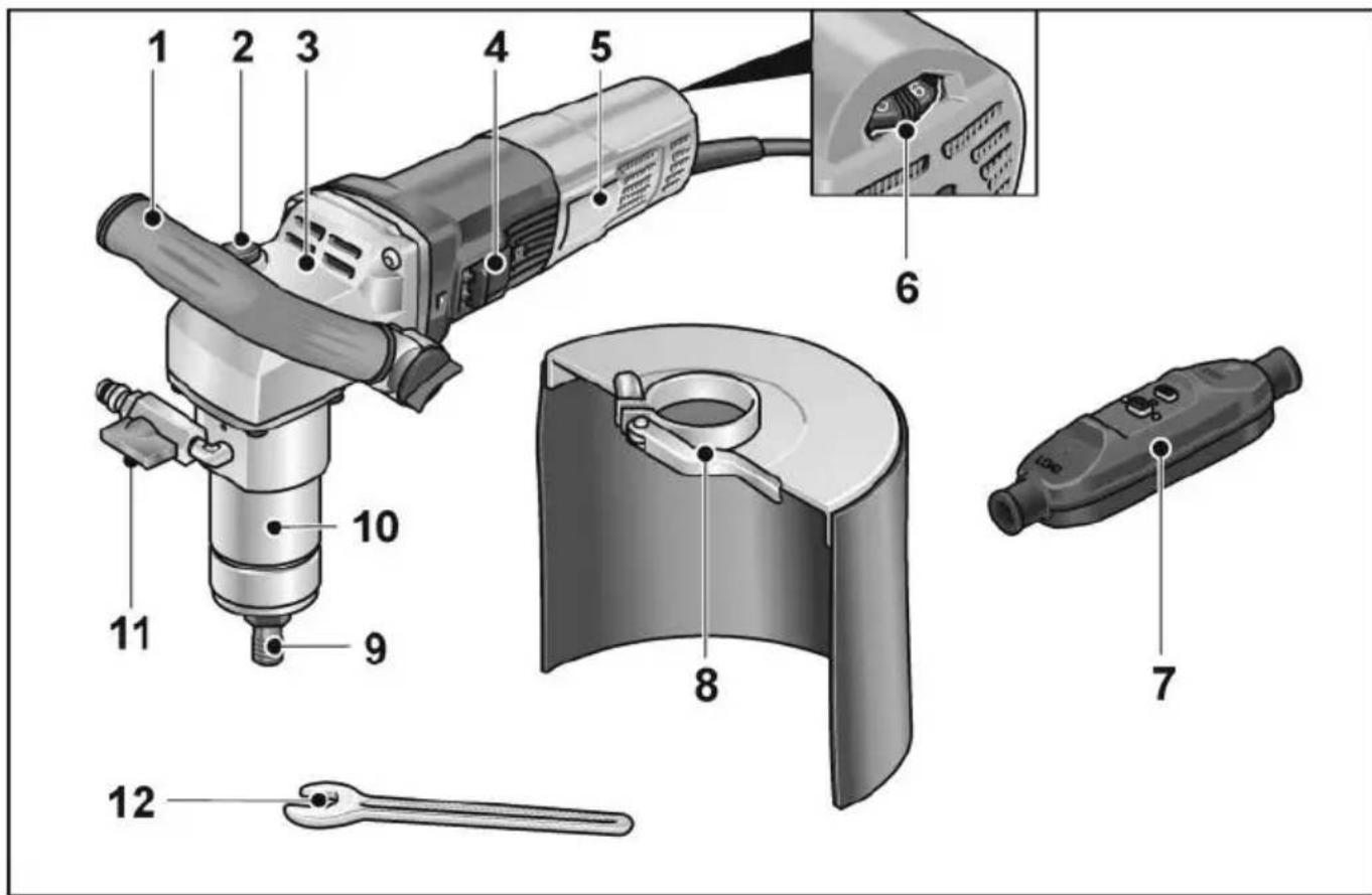
1 Handle
2 Spindle lock
Secures the spindle when the tool is changed.
3 Gearbox
4 Switch rocker
Switches the power tool on and off.
5 Rating plate
6 Dial for preselecting the speed
7 Power cord with PRCD circuit breaker
8 Water splash guard
9 Tool holder
10 Clamping neck
11 Water connection with shut-off valve
12 Open-end wrench SW 17
Instructions for use

WARNING!
Before performing any work on the power tool, pull out the mains plug.
Before initial operation
Unpack the power tool and accessories and check that no parts are missing or were damaged during transport.
Connection to the power supply

WARNING!
These machines may be operated with the supplied PRCD switch only. Before using the machine, always check the PRCD switch.

NOTE
Before actuating the PRCD switch, check whether the electric power tool is switched off.
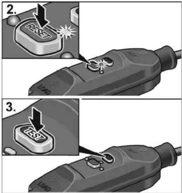
Always check the machine before use:
- Insert the mains plug into the socket.
-
Press "RESET" button. The red indicator light must come on.
-
Press "TEST" button. The PRCD switch must switch off, the indicator light goes out.
-
When the "RESET" button is pressed again, it must be possible to switch on the machine.

WARNING!
If the PRCD switch repeatedly switches off when the machine is switched on or if the PRCD switch does not trip, immediately disconnect the machine from the power supply. Do not continue using the machine. The PRCD switch may be replaced by the manufacturer's customer service only.
Connecting the water

WARNING!
Keep water away from the electric power tool and from people within the operating range. Do not switch on power tools which have not been connected correctly to the water supply. Regularly check that seals, shut-off valve and connectors function correctly.
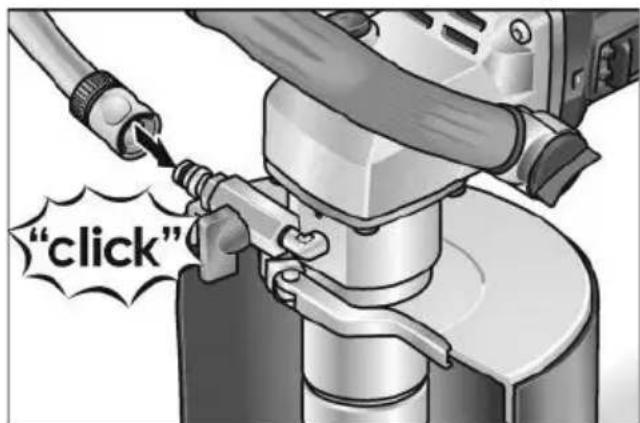
■ Attach 12 " water hose to standard self-locking quick coupling.
■ Do not open shut-off valve until at the place of use and the tool is running.
■ When removing the hose, ensure that no water runs into the machine.
Attaching or changing diamond hole cutter

WARNING!
Before performing any work on the electric power tool, pull out the mains plug.
■ Pull out the mains plug.
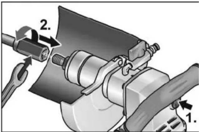
■ Grip tool holder with enclosed open-end wrench 17.
■ Screw diamond hole cutter onto the shank.
■ Tighten drill bit with second open-end wrench 19.
Function test:
■ Insert the mains plug into the socket.
■ Switch on the electric power tool (without locking the button) and leave it running for approx. 30 seconds.
Check for imbalances and vibrations.
■ Switch off the electric power tool.
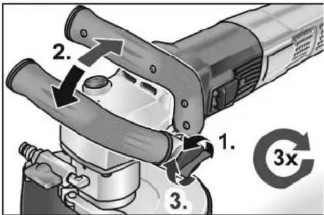
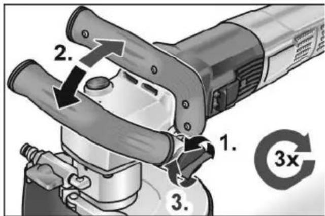
Adjusting the bail handle
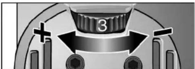
Speed preselection
To set the operating speed, move the dial to the required value.
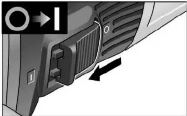
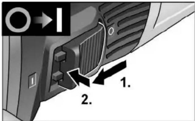
Switching the power tool on/off Short-term operation without detent
natural_image
Close-up of a car's side panel showing a grille and vent, with a directional arrow indicating movement (no text or symbols)■ Push the rocker switch forwards and hold.
■ Release the rocker switch to switch off.
Non-stop operation with detent
i NOTE
If there is a power failure, the switched on power tool will not start running again.
■ Push the rocker switch forwards and engage by pressing the front part.
Switching off the equipment:
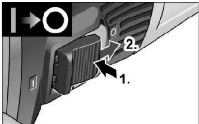
■ To switch off, release the rocker switch by pressing the rear part.

NOTE
The tool will switch off automatically in the event of a short overload. To restart the tool, switch off and back on again.
If overheating occurs due to overload during non-stop operation, the speed of the power tool will be reduced automatically until the power tool has cooled down sufficiently. At the end of the cooling mode, the tool switches off automatically.
To restart the tool, switch off and back on again.
Maintenance and care

WARNING!
Before performing any work on the power tool, pull out the mains plug.

NOTE
Use only original parts supplied by the manufacturer for replacement purposes. The use of non-original parts will invalidate any claims under the manufacturer's warranty.
Cleaning

WARNING!
Do not use water or liquid detergents.
■ Regularly blow out the housing interior and motor with dry compressed air.
■ Clean the protective hood or guide cowl with dry compressed air. Use a brush to remove stubborn deposits.
Repairs
Repairs may only be carried out by an authorised customer service centre.

NOTE
Do not loosen the screws on the motor housing during the warranty period. Failure to comply with this requirement will invalidate any claims under the manufacturer's warranty.
Spare parts and accessories
Exploded drawings and spare part lists can be found on our homepage: www.flex-tools.com
Disposal information

WARNING!
Render disused power tools unusable by removing the power cord.

EU countries only
Do not dispose of electric power tools in the household waste!
In accordance with the European directive 2012/19/EU on Waste Electrical and Electronic Equipment and its incorporation into national law, end-of-life electric power tools must be collected separately and recycled in an environmentally-friendly manner.

NOTE
Please ask your dealer about disposal options.

Declaration of Conformity
The Declarations of conformity are included in Annex 1 to this instruction manual.

Declaration of Conformity
The Declarations of conformity are included in Annex 1 to this instruction manual.
Exemption from liability
The manufacturer and its agent are not liable for any damage and lost profit due to interruption in business caused by the product or by an unusable product.
The manufacturer and its agent are not liable for any damage which was caused by improper use of the power tool or by use of the power tool with products from other manufacturers.
Table des matières
natural_image
Close-up of a car's front panel showing grille and side door, with no visible text or symbolsnatural_image
Mechanical component diagram showing a curved top with labeled parts and directional arrows (no text or symbols)natural_image
Close-up of a car's side panel showing a grille and button, with no visible text or symbolsnatural_image
Close-up of a car's front panel showing a grille and vent, with a directional arrow indicating left motion (no text or symbols)1 Punho
natural_image
Close-up of a car's front panel showing a grille and vent, with a directional arrow indicating left motion (no text or symbols)1 Handgreep
2 Asvergrendeling
natural_image
Close-up of a car's side panel showing a grille and vent, with a directional arrow indicating left motion (no text or symbols)natural_image
Close-up of a car's side panel showing a grille and button, with no visible text or symbols.■ Skub vippekontakten fremad og hold den fast.
■ Slip vippekontakten for at slukke.
natural_image
Close-up of a car's side panel showing a grille and button, with no visible text or symbols.natural_image
Close-up of a car's side panel showing a grille and button, with no visible text or symbols.1 K a h v a
2 Karalukko
natural_image
Close-up of a car's front panel showing a grille and vent, with a directional arrow indicating left motion (no text or symbols)1 X ε 1 ρ o λ α
natural_image
Close-up of a car's side panel showing a grille and vent, with a directional arrow indicating movement (no text or symbols)5 Tutamak
6 Mil kilidi
natural_image
Close-up of a car's side panel showing a grille and vent, with a directional arrow indicating left motion (no text or symbols)natural_image
Close-up of a car's side panel showing a grille and vent, with no visible text or symbols.natural_image
Mechanical component diagram showing a top view with a central knob labeled '3' and directional arrows indicating motion (no text or symbols beyond the number)natural_image
Close-up of a car's side panel showing a grille and vent, with no visible text or symbolsnatural_image
Collection of circular icons representing human, safety, and compliance symbols (no text or labels)natural_image
Mechanical component diagram showing a knob with three arrows indicating rotation or movement (no text or symbols)natural_image
Close-up of a car's front panel showing a grille and button, with no visible text or symbolsnatural_image
Close-up of a car's side panel showing airflow direction and control buttons (no text or symbols)5 R u č k a
6 Blokada vretena
■ Prihvat alata pridržati priloženim vilastim ključem 17.
■ Dijamantni bušač pritegnuti na vreteno.
■ Dijamantni bušač pritegnite drugim vilastim ključem 19.
Ispitivanje funkcije:
■ Utaknite mrežni utikač u utičnicu.
■ Uključite električni alat (bez uglavljivanja) i ostavite ga da radi otprilike 30 sekundi. Provjerite dolazi li do neuravnoteženosti i vibracija.
■ Isključite električni alat.
Pomicanje stremenaste ručke
Odabir broja okretaja
natural_image
Diagram of a mechanical component with arrows indicating motion or force direction (no text or symbols)natural_image
Close-up of a car's side panel showing a grille and vent, with directional arrows indicating movement (no text or symbols)■ Klizač prekidača gurnite prema naprijed i čvrsto držite.
■ Za isključivanje otpustite klizač prekidača.
Neprekidan rad s uglavljivanjem

NAPOMENA
5 Ročaj
6 Blokada vretena
Za blokiranje vretena pri menjavi nastavka.
7 Ohišje pogona
8 Prevesno stikalo
Za vklop in izklop.
■ Vpenjalo pridržite s priloženim viličastim ključem dim. 17.
■ Diamantno krono privijte na vreteno.
■ Diamantno krono zategnite z drugim viličastim ključem dim. 19.
natural_image
Close-up of a car's side panel showing a grille and button, with no visible text or symbols■ Prevesno stikalo potisnite naprej in ga pridržite.
■ Za izklop prevesno stikalo izpustite.
Trajno delovanje z zaklepom
i OPOMBA
natural_image
Mechanical component diagram showing a knob with three arrows indicating rotation or movement (no text or symbols)natural_image
Close-up of a car's side panel showing a grille and button, with no visible text or symbols.natural_image
Close-up of a car's side panel showing a grille and button, with no visible text or symbols.1 Р у к о я т к а
2 Фиксатор шпинделя
natural_image
Close-up of a car's side panel showing a grille and vent, with directional arrows indicating movement (no text or symbols)natural_image
Close-up of a mechanical component with arrows indicating motion or force direction (no text or symbols)natural_image
Close-up of a car's side panel showing a grille and vent, with no visible text or symbolsnatural_image
Close-up of a car's side panel showing a grille and button, with no visible text or symbolsnatural_image
Close-up of a car's front panel showing a grille and button, with a black arrow indicating direction (no text or symbols)natural_image
Diagram of a mechanical component with arrows indicating motion or rotation, no readable text or symbols present.natural_image
Close-up of a car's front panel showing a grille and side-mounted buttons, with no visible text or symbols.Unit 8 Anglo Office Park
Lincoln Road
HP12 3RH, High Wycombe, Buckinghamshire
United Kingdom
Phone: +44 (0)1325 741 793
E-Mail: uk.sales@flex-tools.com