
DD 2G 12LD - Electric drill Flex - Free user manual and instructions
Find the device manual for free DD 2G 12LD Flex in PDF.
| Brand | Flex |
| Model | DD 2G 12LD |
| Product type | Cordless drill/driver |
| Nominal voltage | 12 V |
| Chuck type | Self-tightening chuck, Ø 1.5 – 10 mm |
| Speeds | 2 speeds (slow/high torque, fast/low torque) |
| Torque setting | 17 torque positions + drilling |
| Drilling capacity (wood) | 20 mm |
| Drilling capacity (metal) | 10 mm |
| Weight (with battery) | 1.3 kg |
| Power supply | 12 V lithium-ion battery (compatible with AP 12/2.5; AP 12/5.0; AP 10.8/2.5; AP 10.8/4.0; AP 10.8/6.0) |
| Lighting | Work area LED |
| Rotation direction | Reversible (left/right) |
| Safety | Motor brake, automatic shutdown, overload protection |
| Maintenance | Clean with dry compressed air; do not use water |
| Included accessories | Belt clip, bit holder, charger CA 10.8/CA 12 |
| Main functions | Screwdriving, drilling (wood, metal, ceramic, plastic) |
| General information | Professional use, CE certified, recycling according to WEEE |
Frequently Asked Questions - DD 2G 12LD Flex
User questions about DD 2G 12LD Flex
0 question about this device. Answer the ones you know or ask your own.
Ask a new question about this device
Download the instructions for your Electric drill in PDF format for free! Find your manual DD 2G 12LD - Flex and take your electronic device back in hand. On this page are published all the documents necessary for the use of your device. DD 2G 12LD by Flex.
USER MANUAL DD 2G 12LD Flex
natural_image
Illustration of a handheld electric drill press with a black handle and control panel (no text or symbols visible)
natural_image
Mechanical assembly diagram showing two views of a clamp or bracket mechanism (no text or symbols present)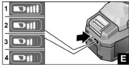
natural_image
Close-up of a drill bit with visible screw and blade, no text or symbols present
flowchart
graph TD
    A["1"] --> B["2"]
    B --> A
    style A fill:#f9f,stroke:#333
    style B fill:#bbf,stroke:#333
natural_image
Close-up of a drill bit with a tool, showing blade and grip (no text or symbols visible)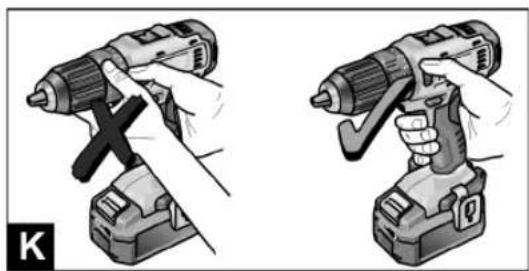
natural_image
Illustration of two different types of electric drillers (no text or symbols present)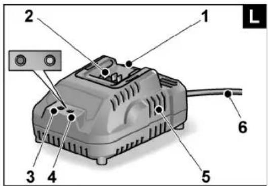
natural_image
Close-up of a mechanical device with a clamped component inserted, showing internal wiring and mounting bracket (no text or symbols visible)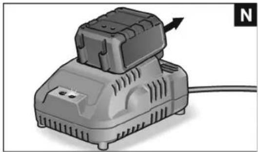
natural_image
Illustration of a portable electric shaver with a cable, showing no text or symbols on the device itself.

DD 2G 12-LD
| GerätetypMachine typeType d'appareilTipo di apparecchioTipo de equipoTipo do aparelhoMachinetypeApparattypeApparattypeMaskintypKonetyyppiTúπος συσκευήςCihaz tipi | Typ urządzeniaKészülék típusaTyp nářadíTyp náradiaTip aparataVrsta orodjaTipul aparatuluiTип на уредаТип прибораSeadmetüüp|rankio tipasierīces modelisطراز الجهاز | BohrschrauberDrill driverPerceuse visseuseTrapano-avvitatoreTaladro atornilladorBerbequim aparafusadorBoorschroevendraaierBore/-skruemaskineBorskrumaskinBorrskruvdragareAkkuporakoneΔρατανοκατσάβιδοDelme/vidalama makinesi | WiertarkowkrętarkaFúró-csavarbehajtóVrtací šroubovákVftací skrutkovačBušilicaVrtalni vijačnikMaşină de găurit/înşurubatБормашина с винтовертДрель-шуруповертTrell-kruvikeerajaGręžtuvas-suktuvasUrbisskrūvgriezisچهاز اللّقاب والـفک |
| t– AP 12/2,5– AP 12/5,0– AP 10,8/2,5– AP 10,8/4,0– AP 10,8/6,0 | minminminminmin | 0–400–700–400–550–85 | |
| M_max – soft– hard | NmNm | 1734 | |
| n_0 – Stufe 1– Stufe 2 | min ^-1 min ^-1 | 0...3500...1300 | |
| D mm 0,8–10 | |||
| D_max | mm 25 | ||
| D_max | mm 10 | ||
| km 0g ,88 | |||
| mAP 12/2,5AP 12/5,0AP 10,8/2,5AP 10,8/4,0AP 10,8/6,0 | kgkgkgkgkg | 0,30,40,30,40,4 | |
| L_pA | dB(A) 66 | ||
| L_wA | dB(A) 77 | ||
| dK 3b | |||
| a_h,D | m/s ^2 | <2,5 | |
| a_h,S | m/s ^2 | <2,5 | |
| K | m/s ^2 | 1,5 |
de
DD 2G 12-LD
Verwendete Symbole

WARNUNG!
-AP 12/2.5
-AP 12/5.0
- AP 10.8/2.5
-AP 10.8/4.0
-AP 10.8/6.0
Eckhard Rühle
Manager Research & Development (R & D)
Klaus Peter Weinper
Head of Quality Department (QD)
29.06.2016
Symbols used in this manual

WARNING!
Denotes impending danger. Non-observance of this warning may result in death or extremely severe injuries.

CAUTION!
Denotes a potentially dangerous situation. Non-observance of this warning may result in injury or damage to property.

NOTE
Denotes application tips and important information.
Symbols on the power tool

Before switching on the power tool for the first time, read the operating manual.

Wear protective goggles.!

Short-circuit-proof safety transformer.
Protect the battery against heat, including prolonged sunshine, and fire. Explosion hazard!.
Do not throw the battery into a fire. Explosion hazard!

The tool is only suitable for use indoors. Do not expose the tool to rain. Store power tools and batteries in dry rooms.

Disposal information (see page 16).
Important safety information

WARNING!
Read all the safety instructions and general instructions. Failure to comply with the safety instructions and general instructions may result in electric shock, fire and/or serious injuries. Keep all safety instructions and general instructions in a safe place for future reference. Before using the power tool, please read the following and act accordingly:
– these operating instructions,
- the "General safety instructions" on the handling of power tools in the enclosed booklet (leaflet no.: 315.915),
– the currently valid site rules and the regulations for the prevention of accidents.
This power tool is state of the art and has been constructed in accordance with the acknowledged safety regulations.
Nevertheless, when in use, the power tool may be a danger to life and limb of the user or a third party, or the power tool or other property may be damaged.
The power tool may be operated only if it is
- for its intended use,
-in perfect working order.
Faults which compromise safety must be repaired immediately.
Intended use
The DD 2G 12-LD cordless drill driver is intended
- for commercial use in industry and trade,
- for inserting and releasing screws,
- for drilling in wood, metal, ceramic and plastic.
Safety instructions for drills and drivers
- Hold the power tool by the insulated gripping surfaces when performing an operation where the cutting accessory or the screw may contact hidden wiring or its own power cord. The screw contacting a "live" wire may make exposed metal parts of the power tool "live" and cause an electric shock.
■ Use auxiliary handles if these are supplied with the power tool. The loss of control may result in injuries.
■ Use suitable detectors to detect concealed power supply cables or consult your local supply company. Contact with electric cables may result in a fire and/or electric shock. A damaged gas pipe may cause an explosion. Cutting into a water pipe will cause damage to property.
■ Switch off the power tool immediately when the cutting accessory jams. Be prepared for high reaction torques which cause kickback. The cutting accessory jams when:
- the power tool is overloaded or
- it snags in the workpiece to be machined.
■ Maintain a firm grip on the power tool. High reaction torques can occur briefly when screws are tightened and released.
- Secure the workpiece. A workpiece is held more securely in a clamping device or vice than by hand.
■ Wait until the power tool has come to a stop before putting it down. The cutting accessory may snag, causing the operator to lose control of the power tool.
■ Use only original batteries with the voltage indicated on the type plate of your power tool. The use of other batteries, e.g. imitations, reconditioned batteries or other makes, increases the risk of injury and damage to property by exploding batteries.
Safety instructions for handling batteries
■ Do not open the battery. Shortcircuiting hazard!
■ Protect the battery against heat, including prolonged sunshine, fire, water and moisture. Explosion hazard!
A damaged or incorrectly used battery may result in the emission of fumes. Ensure a supply of fresh air and consult a doctor in the event of any physical complications. The fumes may irritate the respiratory tracts.
Liquid may leak out of the battery if the battery is incorrectly used. Avoid contact with such liquid. If contact accidentally occurs, rinse with water. If liquid contacts eyes, seek medical attention. Liquid discharged from the battery may cause irritation or burns.
■ Recharge batteries only with chargers recommended by the manufacturer. A charger that is suitable for one type of battery may create a fire hazard when used with another battery.
The battery may be damaged by pointed objects such as e.g. nails or screwdrivers or by external application of force. This may give rise to an internal short circuit, causing the battery to burn, smoke, explode or overheat.
Charger
■ Always check whether the mains voltage matches the voltage indicated on the type plate of the charger.
The charger plug must fit in the power socket. Never modify the plug in any way. Do not use any adapter plugs together with earthed (grounded) power tools. Unmodified plugs and matching power sockets will reduce the risk of electric shock.
■ Only use the charger in dry rooms and avoid all contact with moisture and rain.
The ingress of water into the charger increases the risk of electric shock.
■ Never use the charger if cables, plugs or the device itself are damaged as a result of external influence. Take the charger to the nearest authorised repair shop.
■ Under no circumstances open the charger. In the event of a fault, take it to an authorised repair shop.
■ Do not place any objects on the charger and do not place the charger on soft surfaces. Fire hazard!
Special safety instructions
■ Before carrying out any work on the power tool, move the direction preselector switch (2) to the middle position.
■ Operate the direction preselector switch (2) or torque setting turning dial (4) only when the tool is stopped.
■ Identify the power tool with stickers only. Do not drill any holes into the housing.
Noise and vibration
i NOTE
Values for the A-weighted sound pressure level and for the total vibration values can be found in the table on page 6. The noise and vibration values have been determined in accordance with EN 60745.
WARNING!
The indicated measurements refer to new power tools. Daily use causes the noise and vibration values to change.
i NOTE
The vibration emission level given in this information sheet has been measured in accordance with a measurement method standardised in EN 60745 and may be used to compare one tool with another. It may be used for a preliminary assessment of exposure. The specified vibration emission level represents the main applications of the tool.
However, if the tool is used for different applications, with different cutting accessories or poorly maintained, the vibration emission level may differ.
This may significantly increase the exposure level over the total working period.
To make an accurate estimation of the vibration exposure level, it is also necessary to take into account the times when the tool is switched off or running but not actually in use. This may significantly decrease the exposure level over the total working period.
Identify additional safety measures to protect the operator from the effects of vibration such as: maintain the tool and the cutting accessories, keep the hands warm, organisation of work patterns.
CAUTION!
Wear ear defenders at a sound pressure above 85 dB(A).
Overview (Figure A)
1 Trigger switch
For switching on and off and for accelerating up to maximum rotational speed
2 Direction preselector switch
3 Speed selector switch
4 Turning dial for torque setting
5 Keyless chuck
6 Workplace lighting
7 H a n d l e
8 Insertion slot for battery
9 Li-ion battery (2.5 Ah/4.0 Ah/6.0 Ah)
10 Release button for battery
11 State of charge indicator
12 Belt clip
13 Bit holder
14 Fastening screw


en
DD 2G 12-LD
Instructions for use
Before initial operation
■ Unpack the power tool and accessories and check that no parts are missing or damaged.
■ Attach the belt clip and bit holder with the enclosed fastening screw (Figure B).

NOTE
The batteries are not fully charged on delivery. Prior to initial operation, charge the batteries fully. See "Charger (Figure L)/Charging process".
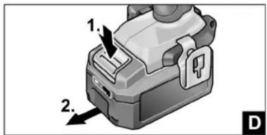
Inserting/replacing the battery
■ Press the charged battery into the power tool until it clicks into place (Figure C).
■ To remove, press the release button (1.) and pull out the battery (2.) (Figure D).

CAUTION!
Protect the battery contacts when the battery is not being used. Loose metal parts may shortcircuit the contacts – Explosion and fire hazard!
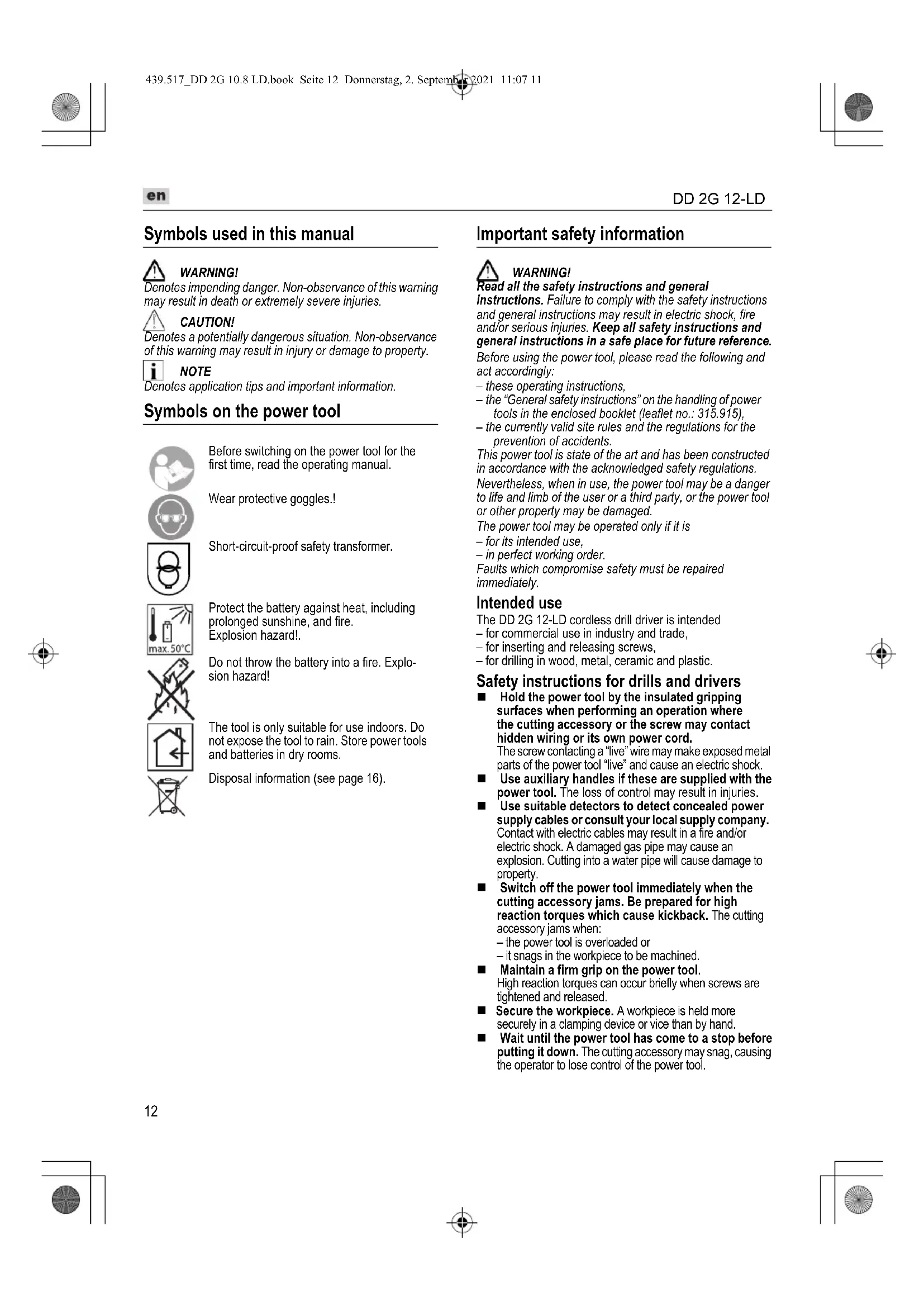
Battery state of charge (Figure E)
■ Press the button to check the state of charge at the state of charge indicator LEDs.
The indicator goes out after 5 seconds.
If one of the LEDs flashes, the battery must be recharged. If none of the LEDs light up after the button is pressed, the battery is faulty and must be replaced.
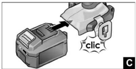
Direction preselection (Figure F)

CAUTION!
Change the direction of rotation only when the power tool is stopped.
■ Move the direction preselector switch to the required position:
- Left: counterclockwise (remove screws, release screws)
- Right: clockwise (drill, insert screws, tighten down screws)
- Middle: switchon interlock (tool change, when working on the power tool)
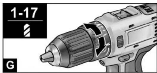
Torque preselection (Figure G)

CAUTION!
Change the torque only when the power tool is stopped.
■ Move the torque setting turning dial to the required position.
1–17: Screwing

Drilling

NOTE
The safety clutch is deactivated in the Drilling setting
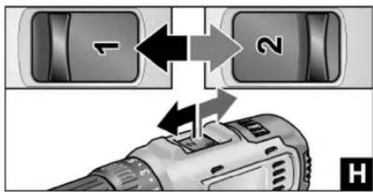
Speed preselection (Figure H)

CAUTION!
Change the speed only when the power tool is stopped.
■ Move the selector switch to the required stage:
1: Low speed, high torque
2: High speed, low torque
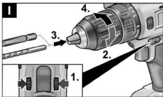
Inserting the tools (Figure I)

CAUTION!
Before carrying out any work on the power tool, move the direction preselector switch (2) to the middle position.
Drill bits with a diameter of 1.5–10 mm, ¼" screwdriver bits and ¼" bit holders are securely held in the chuck.
Grip the power tool firmly with one hand and turn the chuck with the other hand.
- Turn counterclockwise to open the chuck further.
- Turn dockwise to close the chuck.
■ Insert the tool.
■ Close the chuck fully.
■ Move the direction preselector switch to the required position (left/right).
- Carry out a test run to check that the tool is chucked in the centre.
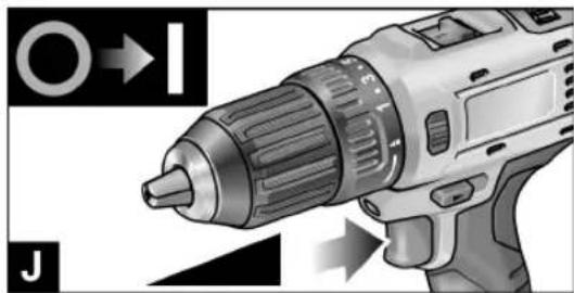
Switching on the power tool (Figure J)
To switch the power tool on:
■ Press the trigger switch.
The power tool trigger switch allows the operator to increase the speed in increments up to the maximum speed.
To switch the power tool off:
■ Release the trigger switch.

NOTE
- The power tool is equipped with a brake which stops the cutting accessory as soon as the trigger switch is released.
- When using the power tool continuously, the operator should work primarily with the trigger switch fully depressed.
Working with the power tool (Figure K)

CAUTION!
Before carrying out any work on the power tool, move the direction preselector switch (2) to the middle position.
-
Insert the battery.
-
Insert the tool (drill bits, srewdriver bits, bit holders).
-
Set torque preselection to the required setting.
-
Set speed to the required setting.
-
Set the required direction of rotation.
-
Hold the power tool with one hand on the handle and assume the working position.
-
Switch on the power tool.
At the end of work:
-
Release the trigger switch.
-
Move the direction preselector switch (2) to the middle position.
Charger (Figure L)
The CA 10,8/ CA 12 charger is designed to charge FLEX batteries of the following types
- AP 12/2,5
- AP 12/5,0
- AP 10.8/2.5
- AP 10.8/4.0
- AP 10.8/6.0
1 Insertion slot for battery
2 Contacts
3 LED fault message (red)
4 LED charge status (green)
5 Ventilation slots
6 Power cord with mains plug


Displays of LED
| red green | |
| off flashes Battery is charging. | |
| off on | Charging process finished.Maintenance charging. |
| See “Charging process”. | |
| flashes off Battery is too hot or too cold. | |
| on off Battery or charger is faulty. | |
| See “Fault messages”. | |
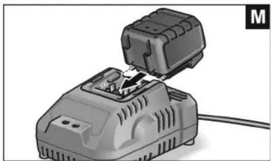
Charging process

CAUTION!
Insert only original batteries in the supplied charger.
■ Insert the charger mains plug.
The LED fault message and the LED charge status light up for a short time.
■ Insert battery into the charger as far as stop (Figure M). The LED charge status flashes and the battery is charged. When the battery is fully charged, the LED charge status is lit continuously.
■ Remove the battery from the charger (Figure N).
■ Pull out the mains plug
Fault messages
If the LED fault message lights up after the battery is inserted into the charger, there is an fault with the battery or charger.
The LED warning message is lit up continuously:
- The battery is too hot or too cold. The charging process starts when the battery reaches the charging temperature (0°C...40°C).
The LED fault message flashes or none of the two LEDs lights up:
- Remove battery from the charger. Check contacts at charger and battery for contamination and clean if necessary. Reinsert battery. The battery is faulty if the same display appears again. Replace battery or have it checked in a professional workshop.
- If this fault message is also displayed with a different battery, then there is a fault with the charger. Have the charger checked by a professional workshop.
Tips for a long battery service life

CAUTION!
- Never charge batteries at temperatures below 0 °C or above 40 °C.
- Do not charge batteries in environments with high air humidity or ambient temperature.
- Do not cover batteries and the charger during the charging process.
– Pull out the charger mains plug at the end of the charging process.
Battery and charger heat up during the charging process.
This is perfectly normal!
Lithium-ion batteries do not exhibit the established "memory effect". Nevertheless, a battery should be completely discharged before charging and the charging process should always be fully completed.
If batteries are not used for an extended period of time, store them partially charged in a cool place.
Maintenance and care
Cleaning

WARNING!
If metals are worked over a prolonged period, electroconductive dust may become deposited inside the housing.
Clean the power tool and ventilation slots at regular intervals. Frequency of cleaning is dependent on the material machined and the duration of use.
■ Regularly blow out the housing interior and motor with dry compressed air. Keep the power tool running while doing this.
Charger

WARNING!
Before performing any work, pull out the mains plug. Do not use water or liquid detergents.
■ Remove dirt and dust from the housing with a brush or a dry cloth.
Repairs
Repairs may be carried out by an authorised customer service centre only.
Spare parts and accessories
For other accessories, in particular cutting accessories, please refer to the manufacturer's catalogues. Exploded drawings and sparepart lists can be found on our homepage: www.flex-tools.com
Transport
The lithium equivalent content of the batteries contained in the scope of delivery is below the relevant limit values. Therefore the battery as a separate component and the power tool with its scope of delivery are not subject to national or international dangerous goods regulations. If several devices containing lithium-ion batteries are transported, these regulations may become relevant and require special safety measures (e.g. for the packaging). In this case acquaint yourself with the regulations that apply to the country of use.


en
DD 2G 12-LD
CE Declaration of Conformity
We declare under our sole responsibility that the product described under page 6 conforms to the following standards or normative documents:
EN 60745 according to the provisions of Directives 2014/30/EU, 2006/42/EC, 2011/65/EC.
Responsible for technical documents: FLEX-Elektrowerkzeuge GmbH, R & D Bahnhofstrasse 15, D-71711 Steinheim/Murr


Eckhard Rühle Manager Research & Development (R & D)
Klaus Peter Weinper Head of Quality Department (QD)
29.06.2016
Declaration of Conformity
We as the manufacturer: FLEX Elektrowerkzeuge GmbH, Business address: Bahnhofstr. 15, 71711 Steinheim, Germany declare under our sole responsibility, that the product(s) described under "Technical specifications" fulfills all the relevant provisions of The Supply of Machinery (Safety) Regulations S.I. 2008/1597 and also fulfills all the relevant provisions of the following UK Regulations: Electromagnetic Compatibility Regulations S.I. 2016/1091, The Restriction of the Use of Certain Hazardous Substances in Electrical and Electronic Equipment Regulations S.I. 2012/3032 and are manufactured in accordance with the following designated Standards: BS EN 60745-1:2010, BS EN 60745-2-1:2010, BS EN 55014-1:2017, BS EN 55014-2:2015 Place of declaration: Steinheim, Germany. Responsible person: Peter Lameli, Technical Director - FLEX-Elektrowerkzeuge GmbH
Contact details for Great Britain: FLEX Power Tools Limited, Unit 8 Anglo Office Park, Lincoln Road, HP 12, 3RH Buckinghamshire, United Kingdom.

Peter Lameli Technical Head

Klaus Peter Weinper Head of Quality Department (QD)
19.05.2021
Disposal information

WARNING!
Render redundant power tools unusable:
- mains operated power tool by removing the power cord, - battery operated power tool by removing the battery.

EU countries only
Do not dispose of electric power tools in the household waste! In accordance with the European Directive 2012/19/EC on Waste Electrical and Electronic Equipment and its incorporation into national law, used power tools must be collected separately and recycled in an environmentally friendly manner.

Raw material recovery instead of waste disposal.
Device, accessories and packaging should be recycled in an environmentally friendly manner. Plastic parts are identified for recycling according to material type.

WARNING!
Do not throw batteries into the household waste, fire or water. Do not open disused batteries.
Batteries should be collected, recycled or disposed of in an environmentally friendly manner.
EU countries only:
In accordance with Directive 2006/66/EC defective or used batteries must be recycled.

NOTE
Please ask your dealer about disposal options.
Exemption from liability
The manufacturer and his representative are not liable for any damage and lost profit due to interruption in business caused by the product or by an unusable product. The manufacturer and his representative are not liable for any damage which was caused by improper use of the product or by use of the product with products from other manufacturers.
Symboles utilisés

AVERTISSEMENT!
Manager Research & Development (R & D)
29.06.2016
9 Batteria al litio (2,5 Ah/4,0 Ah/6,0 Ah)
Klaus Peter Weinper Head of Quality Department (QD)
9 Acumulador de iões de lítio (2,5 Ah/4,0 Ah/6,0 Ah)
Manager Research & Development (R & D)
29.06.2016
- AP 12/5,0
-AP 10,8/2,5 - AP 10,8/4,0
- AP 10.8/6.0
- AP 12/2.5
- AP 12/5.0
- AP 10,8/2,5
- AP 10.8/4.0
- AP 10,8/6,0
Manager Research & Development (R & D)
29.06.2016
9 Li-Ion-batteri (2,5 Ah/4,0 Ah/6,0 Ah)
10 Lösningstast for batteri
11 Batteritilstands-indikator
12 Belteklips
13 Bit-holder
14 Festeskrue


no
DD 2G 12-LD
Bruksanvisning
Før ibruktaking
- AP 12/2,5
- AP 12/5,0
- AP 10.8/2.5
-AP 10.8/4.0 - AP 10.8/6.0
- AP 12/2,5
- AP 12/5,0
- AP 10,8/2,5
- AP 10,8/4,0
- AP 10,8/6,0
1 Plats för batteri
2 Kontakter
Manager Research & Development (R & D)
29.06.2016
9 Litiumioniakku (2,5 Ah/4,0 Ah/6,0 Ah)
- AP 12/2.5
-AP 12/5.0
-AP 10.8/2.5
-AP 10.8/4.0
-AP 10.8/6.0
1 Akkukuilu
2 Liittimet
Manager Research & Development (R & D)
Klaus Peter Weinper
Head of Quality Department (QD)
29.06.2016
iyon akü (2,5B Ah,0 Ah/6.0 Ah)
- AP 12/2.5
- AP 12/5,0
- AP 10,8/2,5
- AP 10.8/4.0
- AP 10,8/6,0
Manager Research & Development (R & D)
Klaus Peter Weinper
Head of Quality Department (QD)
29.06.2016
Manager Research & Development (R & D)
Klaus Peter Weinper
Head of Quality Department (QD)
29.06.2016
9 Li-ion akku (2,5 Ah/4,0 Ah/6,0 Ah)
(2,5 Ah/4,0 Ah/6,0 Ah)
10
- AP 12/2,5
- AP 12/5.0
- AP 10,8/2,5
- AP 10.8/4.0
- AP 10,8/6,0
(2,5 Ah/4,0 Ah/6,0 Ah)
-AP 12/2,5
-AP 12/5,0
- AP 10.8/2.5
-AP 10.8/4.0
- AP 10.8/6.0
Prije stavljanja u rad pročitati uputu za ops-luživanje!
Nositi zaštitu za oči!
Sigurnosni transformator otporan na kratki spoj
(2,5 Ah/4,0 Ah/6,0 Ah)
10 Tipka za deblokadu akumulatora
11 Indikator stanja napunjenosti akumulatora
12 Kopča za pojas
13 Držač nastavka
14 Pričvrsni vijak
Upute za uporabu
Prije stavljanja u pogon
■ Raspakirajte električni alat i pribor i provjerite cjelovitost isporuke, te ima li oštećenja nastalih prilikom transporta
■ Pomoću priloženih vijaka pričvrstite kopču pojasa odn. držač nastavka (B. ábra).
i NAPOMENA
Prilikom isporuke akumulatori nisu potpuno napunjeni. Prije prvog puštanja u rad napunite do kraja akumulatore. U tu svrhu pogledajte „Punjač (L. ábra)/Postupak punjenja“.
- AP 12/2,5
- AP 12/5.0
- AP 10,8/2,5
- AP 10.8/4.0
- AP 10,8/6,0
1 Otvor za umetanje akumulatora
2 Kontakti
3 LED indikator dojave pogreške (crveno)
4 LED indikator stanja napunjenosti (zeleno)
5 Prorezi za ventilaciju
6 Mrežni kabel s mrežnim utikačem
LED indikator
Manager Research & Development (R & D)
29.06.2016
9 Litij-ionska akumulatorska baterija (2,5 Ah/4,0 Ah/6,0 Ah)
10 Gumb za deblokado akumulatorske baterije
11 Prikaz stanja napolnjenosti akumulatorske baterije
12 Sponka za pas
13 Držalo za nastavke
14 Pritrdilni vijak
Navodila za uporabo
Klaus Peter Weinper Head of Quality Department (QD)
(2,5 Ah/4,0 Ah/6,0 Ah)
EN 60745 conform prevederilor Directivei 2014/30/UE, 2006/42/CE, 2011/65/UE.
Conform Directivei Europene 2006/66/CE,
- AP 12/2.5
- AP 12/5,0
- AP 10,8/2,5
- AP 10.8/4.0
- AP 10,8/6,0
Manager Research & Development (R & D)
29.06.2016
- AP 12/5,0 - AP 10,8/2,5 - AP 10,8/4,0 - AP 10,8/6,0
Klaus Peter Weinper Head of Quality Department (QD)
29.06.2016
4 Laetuse taseme LED (roheline)
- AP 12/2,5
- AP 12/5.0
- AP 10,8/2,5
- AP 10.8/4.0
- AP 10,8/6,0
Manager Research & Development (R & D)
29.06.2016


- de
- Verwendete Symbole
- WARNUNG!
- Symbols used in this manual
- WARNING!
- CAUTION!
- NOTE
- Symbols on the power tool
- Important safety information
- Intended use
- Safety instructions for drills and drivers
- Safety instructions for handling batteries
- Charger
- Special safety instructions
- Noise and vibration
- i NOTE
- Overview (Figure A)
- Trigger switch
- en
- DD 2G 12-LD
- Instructions for use
- Before initial operation
- Inserting/replacing the battery
- Battery state of charge (Figure E)
- Direction preselection (Figure F)
- Torque preselection (Figure G)
- Speed preselection (Figure H)
- Inserting the tools (Figure I)
- Switching on the power tool (Figure J)
- Working with the power tool (Figure K)
- Charger (Figure L)
- Charging process
- Fault messages
- The LED warning message is lit up continuously:
- The LED fault message flashes or none of the two LEDs lights up:
- Tips for a long battery service life
- Maintenance and care
- Cleaning
- Repairs
- Spare parts and accessories
- Transport
- CE Declaration of Conformity
- Declaration of Conformity
- Disposal information
- Exemption from liability
- Symboles utilisés
- AVERTISSEMENT!
- Acumulador de iões de lítio (2,5 Ah/4,0 Ah/6,0 Ah)
- no
- Bruksanvisning
- Før ibruktaking
- 10
- Tipka za deblokadu akumulatora
- Kopča za pojas
- Držač nastavka
- Pričvrsni vijak
- Upute za uporabu
- Prije stavljanja u pogon
- i NAPOMENA
- Navodila za uporabo
Brand : Flex
Model : DD 2G 12LD
Category : Electric drill