
LR 65 Professional - Laser level BOSCH - Free user manual and instructions
Find the device manual for free LR 65 Professional BOSCH in PDF.
| Product Type | Laser receiver cell for rotary levels |
| Brand | Bosch |
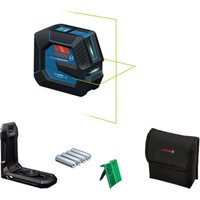
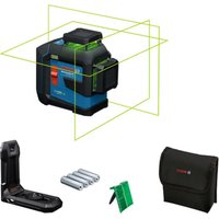
| Model | LR 65 Professional |
| Detectable wavelengths | 500 – 570 nm (green laser) |
| Maximum range | Up to 325 m (with GRL 650 CHVG) |
| Reception angle | ±35° |
| Detectable rotation speeds | > 120 rpm |
| Reception accuracy | 5 levels: ±0.5 mm; ±1 mm; ±2 mm; ±5 mm; ±10 mm |
| Dimensions (L × W × H) | 175 × 79 × 33 mm |
| Weight | 0.38 kg (according to EPTA 01:2014) |
| Power supply | 2 AA batteries (1.5 V LR6) – alkaline recommended |
| Battery life | Approximately 50 hours |
| Display | Front and rear backlit screens with LED indicators |
| Connectivity | Bluetooth® 5.0/4.X Low Energy, class 1, max. range 100 m |
| Special functions | CenterFind® and CenterLock® modes, anti-strobe light filter, last signal memory |
| Protection rating | IP 67 (dust-tight and temporary immersion) |
| Operating temperature | -10 °C to +50 °C |
| Storage temperature | -20 °C to +70 °C |
| Max. operating altitude | 2000 m |
| Cleaning | Soft, damp cloth, without solvents or immersion |
| Included accessories | Mounting bracket, target plate (depending on version), batteries |
| Safety | Do not use in explosive atmospheres, avoid exposing magnets to medical implants |
| Repairability | Entrust to a qualified repairer using original Bosch parts |
| Serial number | Indicated on the rating label (12) |
Frequently Asked Questions - LR 65 Professional BOSCH
User questions about LR 65 Professional BOSCH
0 question about this device. Answer the ones you know or ask your own.
Ask a new question about this device
Download the instructions for your Laser level in PDF format for free! Find your manual LR 65 Professional - BOSCH and take your electronic device back in hand. On this page are published all the documents necessary for the use of your device. LR 65 Professional by BOSCH.
USER MANUAL LR 65 Professional BOSCH
natural_image
Blank white image with a thin blue border (no text, symbols, or markings)

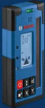
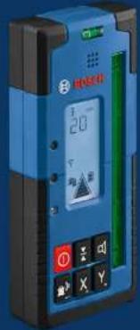
BOSCH
LR Professional
60|65G
English ...... Page 14
natural_image
Technical illustration of a mechanical device with two views showing assembly or inspection (no text or symbols present)5
E
F
natural_image
3D rendering of a handheld device with control buttons and a white plastic casing (no visible text or symbols)Deutsch
Sicherheitshinweise

| 50-100% | |
| 5-50% | |
| 2-5% | |
| 0-2% |
natural_image
Technical diagram showing two views of a device with internal components and alignment lines (no text or symbols)natural_image
Diagram showing two views of a device with internal components and alignment lines (no text or symbols)www.bosch-pt.com/serviceaddresses
Entsorgung
All instructions must be read and observed. The safeguards integrated into the measuring tool may be compromised if the measuring tool is not used in accordance with these
instructions. STORE THESE INSTRUCTIONS IN A SAFE PLACE.
▶ Have the measuring tool serviced only by a qualified specialist using only original replacement parts. This will ensure that the safety of the measuring tool is maintained.
▶ Do not use the measuring tool in explosive atmospheres which contain flammable liquids, gases or dust. Sparks may be produced inside the measuring tool, which can ignite dust or fumes.
When operating the measuring tool, loud signal tones may sound under certain circumstances. For this reason, keep the measuring tool away from your ears and from other persons. The loud sound can damage hearing.

Keep the magnet away from implants and other medical devices, e.g. pacemakers or insulin pumps. The magnet generates a field that can impair the function of implants and medical devices.
▶ Keep the measuring tool away from magnetic storage media and magnetically-sensitive devices. The effect of the magnets can lead to irreversible data loss.
Caution! When using the measuring tool with Bluetooth®, a fault may occur in other devices and systems, aeroplanes and medical devices (e.g. pacemakers, hearing aids). Also, damage to people and animals in the immediate vicinity cannot be completely excluded. Do not use the measuring tool with Bluetooth® in the vicinity of medical devices, petrol stations, chemical plants, areas with a potentially explosive atmosphere and in blasting areas. Do not use the measuring tool with Bluetooth® on aeroplanes. Avoid using the product near your body for extended periods.
The Bluetooth® word mark and logos are registered trademarks owned by Bluetooth SIG, Inc. and any use of such marks by Robert Bosch Power Tools GmbH is under license.
Product Description and Specifications
Please observe the illustrations at the beginning of this operating manual.
Intended Use
The laser receiver is intended to quickly find rotating laser beams of the wavelength specified in the technical data. The LR 60 laser receiver is also intended for controlling the GRL 600 CHV via Bluetooth ^® , and the LR 65 G laser receiver for controlling the GRL 650 CHVG.
The laser receiver is suitable for indoor and outdoor use.
Product Features
The numbering of the product features refers to the illustration of the laser receiver on the graphics page.
(1) Laser beam reception area
(2) "Laser beam above centre line" LED direction indicator
(3) LED for centre line
Technical Data
| Laser receiver LR 60 LR 65 G | |
| Article number | 3 601 K69 P.. 3 601 K69 T.. |
| Receivable wavelength 600–800 nm 500–570 nm | |
| Max. work areaA) | |
| - With GRL 600 CHV 300 m - | |
16 | English
Laser receiver LR 60 LR 65 G
| - With GRL 650 CHVG - 325 m | ||
| Reception angle ±35° ±35° | ||
| Receivable rotation speed >120 min | -1 | >120 min-1 |
| Reception accuracyB(C) | ||
| - Very fine ±0.5 mm ±0.5 mm | ||
| - Fine ±1 mm ±1 mm | ||
| - Medium ±2 mm ±2 mm | ||
| - Coarse ±5 mm ±5 mm | ||
| - Very coarse ±10 mm ±10 mm | ||
| Operating temperature -10°C to +50°C | -10°C to +50°C | |
| Storage temperature | -20°C to +70°C | -20°C to +70°C |
| Max. altitude 2000 m | 2000 m | |
| Relative air humidity max. | 90% | 90% |
| Pollution degree according to IEC 61010-1 | 2D) | 2D) |
| Bluetooth® laser receiver | ||
| - Class | 1 | 1 |
| - Compatibility | Bluetooth® 5.0/4.X (Low Energy)E) | Bluetooth® 5.0/4.X (Low Energy)E) |
| - Max. signal range F) | 100 m | 100 m |
| - Operating frequency range | 2402-2480 MHz | 2402-2480 MHz |
| - Max. transmission power | 6.3 mW | 6.3 mW |
| Batteries | 2 × 1.5 V LR6 (AA) | 2 × 1.5 V LR6 (AA) |
| Approx. operating time | 50 h | 50 h |
| Weight according to EPTA-Procedure 01:2014 | 0.38 kg | 0.38 kg |
| Dimensions (length × width × height) | 175 × 79 × 33 mm | 175 × 79 × 33 mm |
| Protection rating | IP 67 | IP 67 |
A) The working range may be reduced by unfavourable environmental conditions (e.g. direct sunlight).
B) Dependent on the distance between the laser receiver and the rotary laser and on the laser class and laser type of the rotary laser
C) The reception accuracy may be reduced by unfavourable environmental conditions (e.g. direct sunlight).
D) Only non-conductive deposits occur, whereby occasional temporary conductivity caused by condensation is expected.
E) When using Bluetooth® Low Energy devices, it may not be possible to establish a connection depending on the model and operating system. Bluetooth® devices must support the SPP profile.
F) The signal range may vary greatly depending on external conditions, including the receiving device used. The Bluetooth ^® range may be significantly weaker inside closed rooms and through metallic barriers (e.g. walls, shelving units, cases, etc.). For clear identification of your laser receiver, see the serial number (12) on the type plate.
Assembly
Inserting/Changing the Batteries
Alkali-manganese batteries are recommended for the laser receiver.
Turn the locking mechanism (14) of the battery compartment cover into position ⚙ (e.g. using a coin). Open the battery compartment cover (13) and insert the batteries.
When inserting the batteries, ensure that the polarity is correct according to the illustration on the inside of the battery compartment.
Close the battery compartment cover (13) and turn the locking mechanism (14) of the battery compartment cover into position.
The battery indicator (i) shows the state of charge of the batteries of the laser receiver:
| Indicator | Capacity |
| 50 - 100% | |
| 5 - 50% | |
| 2 - 5% |
Indicator Capacity

0 - 2%
Always replace all the batteries at the same time. Only use batteries from the same manufacturer and which have the same capacity.
▶ Take the batteries out of the laser receiver when you are not using it for a prolonged period of time. The batteries can corrode and self-discharge during prolonged storage in the laser receiver.
Rotary Laser Battery Charge Indicator
The battery charge indicator (a) shows the state of charge of the battery pack/batteries of the rotary laser, provided that the rotary laser is switched on and a Bluetooth® connection has been established between the laser receiver and the rotary laser.
Indicator Capacity
| 60 - 100% | |
| 30 - 60% | |
| 5 - 30% | |
| 0 - 5% |
Operation
Starting operation
▶ Protect the laser receiver against moisture and direct sunlight.
Do not subject the laser receiver to extreme temperatures or variations in temperature. As an example, do not leave it in vehicles for longer periods. In case of large variations in temperature, allow the laser receiver to adjust to the ambient temperature before putting it into operation. In case of extreme temperatures or variations in temperature, the accuracy of the laser receiver can be impaired.
Keep the work area free from obstacles that could reflect or obstruct the laser beam. For example, cover any reflective or shiny surfaces. Do not measure through panes of glass or similar materials. The measurements may be distorted by a reflected or obstructed laser beam.
Setting up the laser receiver (see figure A)
Position the laser receiver so that the laser beam can reach the reception area (1). Align it so that the laser beam runs straight through the reception area (as shown in the figure). For rotary lasers with multiple operating modes, select the horizontal or vertical operation with the highest rotational speed.
Switching On/Off
▶ A loud audio signal sounds when switching on the laser receiver. Therefore, keep the laser receiver away from your ear or other persons when switching it on. The loud sound can damage hearing.
To switch on the laser receiver, press the on/off button (19). All display indicators and all LEDs light up briefly and an audio signal sounds.
To switch off the laser receiver, press and hold the on/off button (19) until all LEDs briefly light up and the display goes out. With the exception of the setting for the display lighting, all settings are saved when the laser receiver is switched off.
If no button on the laser receiver is pressed for approx. 10 min and no laser beam reaches the reception area (1) for 10 min, then the laser receiver will automatically switch it- self off to preserve battery life.
Connection to the Rotary Laser
In the default factory setting, the rotary laser and the supplied laser receiver are already connected via Bluetooth®. For the existing connection, the Bluetooth® connection indicator (b) appears in the display of the laser receiver.
To reconnect the laser receiver or to connect an additional laser receiver with the rotary laser, press and hold the Bluetooth® button on the rotary laser until the symbol for establishing a connection to the remote control/laser receiver appears in the display of the rotary laser. Then press and hold the X-axis button (16) and Y-axis button (15) on the laser receiver until P-- appears in the text display (e).
Confirmation as to whether a connection has successfully been established will be shown on the display of the rotary laser. POK will appear on the text indicator (e) of the laser receiver.
If the connection between the rotary laser and the laser receiver cannot be established, PNK will appear in the text display (e) of the laser receiver and the error message for a failed connection will be shown in the display of the rotary laser. For troubleshooting, consult the operating instructions for the rotary laser.
Direction indicators
The position of the laser beam in the reception area (1) is indicated as follows:
- On the display (5) on the front and rear of the laser receiver by means of the "laser beam below centre line" direction indicator (f), the "laser beam above centre line" direction indicator (j) and the centre line indicator (h)
- Optionally, by means of the red "laser beam below centre line" LED direction indicator (4), the blue "laser beam above centre line" LED direction indicator (2) and the green centre line LED (3) on the front of the laser receiver - By an audio signal (optional).
On the first pass of the laser beam through the reception area (1) a short audio signal always sounds and the red "laser beam below centre line" LED direction indicator (4) and the blue "laser beam above centre line" LED direction
18 | English
indicator (2) briefly light up (even if the audio signal and/or LED direction indicators have been switched off).
Laser receiver too low: If the laser beam hits the upper half of the reception area (1), then the "laser beam above centre line" direction indicator (j) appears in the display. If the LEDs are switched on, the blue "laser beam above centre line" LED direction indicator (2) lights up. If the audio signal is switched on, a signal sounds in a slow rhythm.
Move the laser receiver upwards in the direction of the arrow. When the laser beam is close to the centre line, only the tip of the "laser beam above centre line" direction indicator (j) is shown.
Laser receiver too high: If the laser beam hits the lower half of the reception area (1), then the "laser beam below centre line" direction indicator (f) appears in the display. If the LEDs are switched on, the red "laser beam below centre line" LED direction indicator (4) lights up. If the audio signal is switched on, a signal sounds in a fast rhythm.
Move the laser receiver downwards in the direction of the arrow. When the laser beam is close to the centre line, only the tip of the "laser beam below centre line" direction indicator (f) is shown.
Laser receiver centred: If the laser beam hits the reception area (1) at the height of the centre line, then the centre line indicator (h) appears in the display. If the LEDs are switched on, the green centre line LED (3) lights up.
If the audio signal is switched on, a continuous tone sounds.
Memory function of last reception: If the laser receiver is moved so that the laser beam leaves the reception area (1) again, the last displayed direction indicator for "laser beam above centre line" (j) or "laser beam below centre line" (f) flashes for a short time. This indicator can be switched on or off via the settings menu.
Relative height indicator (see figure B)
If the laser beam hits the reception area (1), the clearance between the laser beam and the centre line of the laser receiver is shown in the text display (e) as an absolute value.
The measuring unit for the height indicator can be changed in the settings menu ("mm" or "in").
Display illumination
The displays (5) on the front and rear of the laser receiver can be illuminated. The display illumination function is switched on:
- When the laser receiver is switched on
- With each press of a button
- If the laser beam moves over the reception area (1).
The display illumination function automatically switches off:
- 30 s after each button press, if no laser beam reaches the reception area
- 2 min after the last button press and if the position of the laser beam in the reception area does not change.
The display illumination can be switched off in the settings menu.
The setting for display illumination is not saved when the laser receiver is switched off. After switching on the laser receiver, the display illumination is always switched on.
Settings
Selecting the setting of the centre line indicator
You can specify the accuracy with which the position of the laser beam is indicated as "centred" on the reception area (1).
The current setting for the centre line indicator (c) can be seen in the indicator for reception accuracy.
To change the reception accuracy, press the button for adjusting the reception accuracy (18) as many times as needed for the required setting to be shown in the display. With each press of the button for adjusting the reception accuracy, the respective value for the reception accuracy appears in the text display (e) for a short time.
The setting for reception accuracy is saved when the tool is switched off.
Laser Beam Indicator Audio Signal
The position of the laser beam on the reception area (1) can also be indicated by an audio signal.
The volume level can be changed or the audio signal switched off.
To change the volume level or switch off the audio signal, push the audio signal button (20) until the required volume level is indicated on the display. At a low volume, the audio signal indicator (g) appears on the display with one bar; at a high volume, the indicator appears with three bars. When the audio signal is switched off, the indicator goes out. Independent of the audio signal setting, a short beep sounds at low volume level when the laser beam first makes contact with the reception area (1).
The setting for the audio signal is saved when the laser receiver is switched off.
Settings menu
To call up the settings menu: Briefly press the X-axis button (16) and the Y-axis button (15) on the laser receiver at the same time.
To change the setting within a submenu: Press the X-axis button (16) or the Y-axis button (15) to switch between the settings. The last selected setting is automatically saved when exiting the menu.
To change the submenu: Briefly press the CenterFind mode button (17) to move to the next submenu.
To exit the settings menu: Press and hold the CenterFind mode button (17) until the settings menu closes. Alternatively, the settings menu is automatically closed approximately 10 seconds after the last press of a button.
The following submenus are available:
- Unit of measurement of the relative height indicator:
When calling up the unit of measurement menu, the currently selected unit of measurement is shown in the text display (e), while the available units of measurement are shown in the unit of measurement indicator (d) above it.
- LED direction indicators (LED): The 3 LED direction indicators (2), (4) and (3) can be adjusted with regard to their brightness or switched off. The LEDs light up in their selected setting.
- Display lighting (LIT): The display lighting can be switched on (green LED lights up) or switched off (red LED lights up).
- Memory function for last reception (MEM): The indicator for the direction in which the laser beam has left the reception area can be switched on (green LED lights up) or switched off (red LED lights up).
- Centre functions (CF/CL) (LR 65 G): You can choose between CenterFind (CF) mode and CenterLock (CL) mode. The current mode appears in the text display (e).
With the exception of the setting for the display lighting, all settings are saved when the laser receiver is switched off.
Functions
CenterFind mode (see figure C)
In CenterFind mode, the rotary laser automatically attempts to align the laser beam to the centre line of the laser receiver by moving the rotation head up and down.
If the rotary laser is in the horizontal position, the laser beam can be aligned in relation to the X-axis of the rotary laser, to the Y-axis or to both axes at the same time (see "Inclination determination with CenterFind mode (see figure D)", page 19). If the rotary laser is in the vertical position, only alignment to the Y-axis is possible.
Start CenterFind mode:
natural_image
Diagram showing a car with a sensor and its internal components, including a magnified view of the front wheel (no text or symbols present)Position the rotary laser and laser receiver so that the laser receiver is situated in the direction of the X-axis or the Y-axis of the rotary laser. Align the laser receiver so that the required axis is at a right angle to the reception area (1).
If the laser beam is aligned to both axes, then place a laser receiver connected to the rotary laser in the direction of the X- and Y-axis respectively. Each laser receiver must be situated within the pivoting range of ±8.5% of the rotary laser. Switch on the rotary laser in rotational operation.
LR 65 G: In the settings menu, the centre function must be put in CenterFind (CF) mode. When aligning to two axes of the rotary laser, this applies to both laser receivers.
To start the CenterFind mode for the X-axis, either press and hold the CenterFind (17) mode button, or press and hold the CenterFind (17) mode button, together with the X-axis button (16).
To start the CenterFind mode for the Y-axis, press and hold the CenterFind (17) mode button, together with the Y-axis button (15).
Should the laser beam be aligned to both axes at the same time, CenterFind mode must be started separately on each laser receiver.
Following the start of CenterFind mode, the rotary head on the rotary laser moves up and down. During the search process, CFX (X-axis) or CFY (Y-axis) appears in the text display (e).
If the laser beam hits the reception area (1) at the height of the centre line of the laser receiver, the centre line indicator (h) will appear and XOK (X axis) and YOK (Y axis) will appear in the text display (e). The value of the incline that is found is displayed on the rotary laser. CenterFind mode will be ended automatically.
Cancelling CenterFind mode:
To cancel the CenterFind mode, press and hold the CenterFind mode button (17).
Troubleshooting:
If the laser beam was unable to find the centre line of the laser receiver within the pivoting range, ERR appears in the text display (e) and all LED direction indicators light up. Press any button on the rotary laser and one on the laser receiver to close the error messages. Reposition the rotary laser and laser receiver so that the laser receiver is situated within the pivoting range of ±8.5% of the rotary laser. Ensure that the laser receiver is aligned to the X-axis or Y-axis so that the laser beam can pass through the reception area (1) horizontally. Then restart the CenterFind mode.
LR 65 G: If both axes of the rotary laser should be aligned to a laser receiver, the same centre function must be set on both laser receivers. A combination of CenterFind mode and CenterLock mode is not possible.
If CenterLock mode is already set on one axis and CenterFind mode is started on the other axis, ERR and CL will appear alternately in the text display (e).
Select CenterFind mode on both laser receivers and re-start the function.
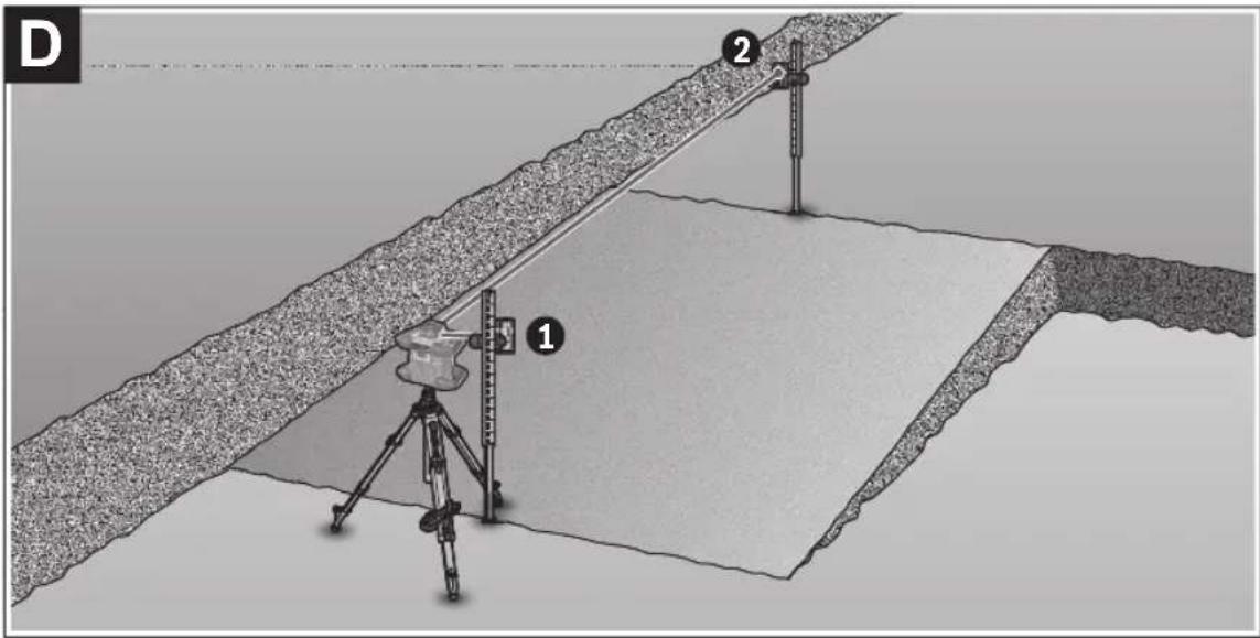
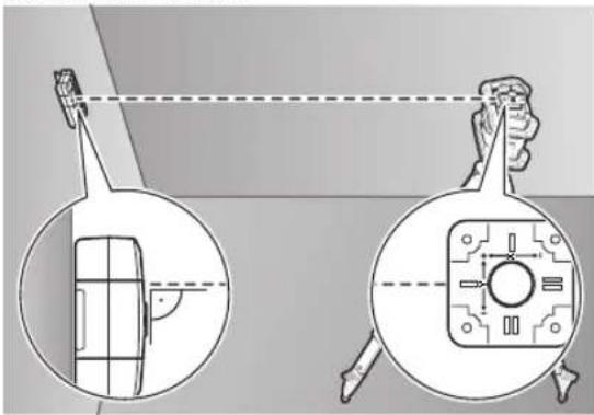
Inclination determination with CenterFind mode (see figure D)
Using CenterFind mode, the inclination of a surface can be measured up to max. 8.5 %. To do this, set up the rotary laser at one end of the inclined surface in a horizontal position on a tripod. The X- or Y-axis of the rotary laser must be aligned with the inclination to be determined. Switch on the rotary laser and allow it to level in.
Secure the laser receiver to a measuring rod (25) with the holder. Place the measuring rod near to the measuring tool (at the same end of the inclined surface). Align the height of the laser receiver on the measuring rod so that the laser beam of the rotary laser is indicated as "centred" ①.
20 | English
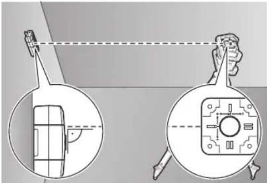
Then place the measuring rod with the laser receiver at the other end of the inclined surface at ②. Ensure that the position of the laser receiver on the measuring rod remains unchanged.
Start CenterFind mode for the axis to which the inclined surface is aligned. At the end of CenterFind mode, the inclination of the surface is shown on the rotary laser.
CenterLock mode (LR 65 G)
In CenterLock mode, the rotary laser automatically attempts to align the laser beam to the centre line of the laser receiver by moving the rotation head up and down. In contrast to the CenterFind mode, the position of the laser receiver is continually checked and the inclination of the rotary laser automatically adjusted. No slope values appear on the display of the rotary laser.
Alignment is possible for the X-axis and Y-axis both when the rotary laser is in a horizontal position and when it is in a vertical position.
Start CenterLock mode:
Position the rotary laser and laser receiver so that the laser receiver is situated in the direction of the X-axis or the Y-axis of the rotary laser. Align the laser receiver so that the required axis is at a right angle to the reception area (1).
If the laser beam is aligned to both axes, then place a laser receiver connected to the rotary laser in the direction of the X- and Y-axis respectively. Each laser receiver must be situated within the pivoting range of ±8.5% of the rotary laser. Switch on the rotary laser in rotational operation.
In the settings menu of the laser receiver, the centre function must be put in CenterLock (CL) mode. When aligning to two axes of the rotary laser, this applies to both laser receivers.
To start the CenterLock mode for the X-axis, either press and hold the CenterFind (17) mode button, or press and hold the CenterFind (17) mode button, together with the X-axis button (16).
To start the CenterLock mode for the Y-axis, press and hold the CenterFind (17) mode button, together with the Y-axis button (15).
Should the laser beam be aligned to both axes at the same time, CenterLock mode must be started separately on each laser receiver.
Following the start of CenterLock mode, the rotary head on the rotary laser moves up and down. During the search process, CLX (X-axis) or CLY (Y-axis) appears in the text display (e).
If the laser beam hits the reception area (1) at the height of the centre line of the laser receiver, the centre line indicator (h) and the text display (e) LOC will appear. The
CenterLock symbol is displayed on the rotary laser on the start screen for the corresponding axis.
In the event of changes to the position of the laser receiver or rotary laser, the inclination is automatically adjusted on the rotary laser.
▶ Take great care when working with the CenterLock mode that rotary lasers and laser receivers are not moved unintentionally. Incorrect measurements can arise from the automatic adjustment of the inclination with every change of position.
Cancelling CenterLock mode:
To cancel or end the CenterLock mode, press and hold the CenterFind mode button (17). If the laser beam was already successfully aligned with the centre line of the laser receiver at this point, the set inclination remains on the rotary laser even when CenterLock mode is cancelled.
Troubleshooting:
If the laser beam was unable to find the centre line of the laser receiver within 2 min (no matter whether at the start of the mode or after changes to position), ERR appears in the text display (e) and all LED direction indicators light up.
Press any button on the rotary laser and one on the laser receiver to close the error messages. Reposition the rotary laser and laser receiver so that the laser receiver is situated within the pivoting range of ±8.5% of the rotary laser. Ensure that the laser receiver is aligned to the X-axis or Y-axis so that the laser beam can pass through the reception area (1) horizontally. Then restart the CenterLock mode.
If both axes of the rotary laser should be aligned to a laser receiver, the same centre function must be set on both laser receivers. A combination of CenterLock mode and CenterFind mode is not possible.
If CenterFind mode is already set on one axis and CenterLock mode is started on the other axis, ERR and CF will appear alternately in the text display (e). Select CenterLock mode on both laser receivers and re-start the function.
Anti-strobe protection filter
The laser receiver has electronic filters for strobe light. The filters protect against, for example, interference from the warning lights of construction machinery.
Working Advice
Aligning with the spirit level
The laser receiver can be aligned vertically (plumb line) with the spirit level (7). If a laser receiver is mounted at an angle, it will give incorrect measurements.
Marking
You can mark the position of the laser beam at the centre mark (9) on the left and right of the laser receiver when the beam hits the centre of the reception area (1).
When marking, take care to align the laser receiver so that it is exactly vertical (with a horizontal laser beam) or horizontal (with a vertical laser beam), as otherwise the marks are offset with respect to the laser beam.
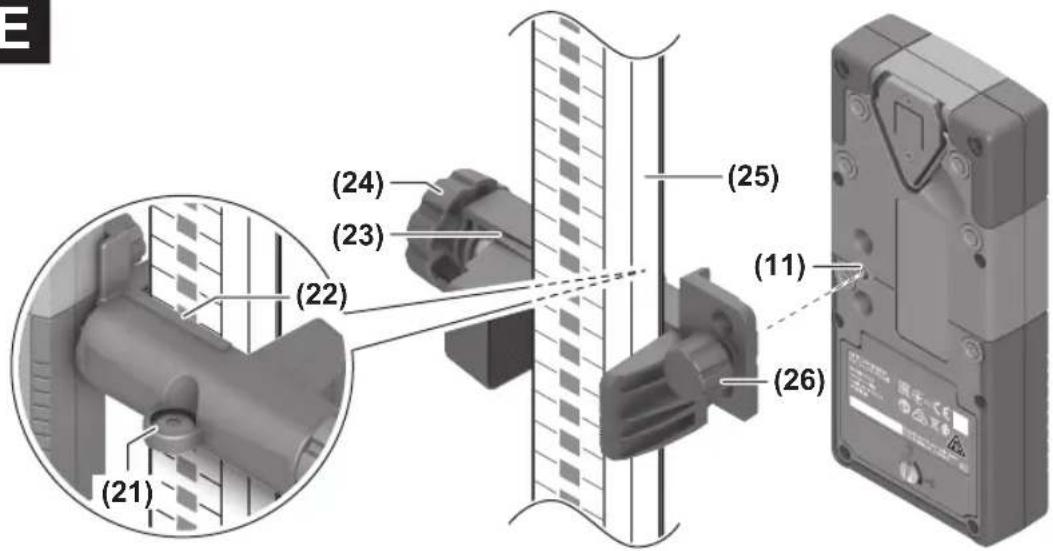
Attaching using the holder (see figure E)
You can use the holder (23) to attach the laser receiver to a measuring rod (25) (accessory) as well as to other auxiliary tools with a width of up to 65 mm.
Screw the holder (23) to the mount (11) on the rear side of the laser receiver with the fastening screw (26).
Loosen the rotary knob (24) on the holder, slide the holder onto the measuring rod (25) and retighten the rotary knob (24).
You can use the spirit level (21) to ensure that the holder (23) is horizontally aligned along with the laser receiver. If the laser receiver is mounted at an angle, it will give incorrect measurements.
The centre line reference (22) on the holder is situated at the same height as the centre marking (9) and can be used for marking the laser beam.
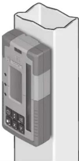
Attaching using a magnet (see figure F)
If an attachment is not required to be especially secure, the laser receiver can be attached to steel parts using the magnets (10).
Rectifying errors
| Text display (e) Problem Corrective measures | ||
| PNK | Failed to establish Bluetooth® connection to the GRL 600 CHV or GRL 650 CHVG rotary laser | Briefly press the on/off button on the rotary laser to close the error message. Restart the process for establishing the connection.If it is not possible to establish a connection, please contact a Bosch customer service agent. |
| ERR | Calibration of the GRL 600 CHV or GRL 650 CHVG rotary laser failed | Read and observe the operating instructions for the GRL 600 CHV or GRL 650 CHVG. |
| CenterFind mode or CenterLock mode failed | Press any button to close the error message. Check the position of the rotary laser and laser receiver before re-starting the function. | |
| LR 65 G: | ||
| ERR and CL in alternation | CenterFind mode cannot be started because the rotary laser is already working in CenterLock mode. | Select CenterFind mode on both laser receivers and re-start the function. |
| ERR and CF in alternation | CenterLock mode cannot be started because the rotary laser is already working in CenterFind mode. | Select CenterLock mode on both laser receivers and re-start the function. |
Assignment of Functions
| Function possible with LR 60 and GRL 600 CHV Rotary laser with red laser beam | (600–800 nm) | |
| Battery charge indicator of the rotary laser ● – | ||
| Direction indicators for the position of the laser beam ● ● | ||
| Relative height indicator ● ● | ||
| CenterFind mode | ● | - |
| CenterLock mode | - | - |
| Function possible with LR 65 G and GRL 650 CHVG Rotary laser with green laser beam (500-570 nm) | ||
| Battery charge indicator of the rotary laser ● - | ||
| Direction indicators for the position of the laser beam ● ● | ||
| Relative height indicator ● ● | ||
| CenterFind mode | ● | - |
| CenterLock mode | ● | - |
22 | Français
Maintenance and Service
Maintenance and Cleaning
Always keep the laser receiver clean.
Do not immerse the laser receiver in water or other liquids. Wipe off any dirt using a damp, soft cloth. Do not use any detergents or solvents.
After-Sales Service and Application Service
Our after-sales service responds to your questions concerning maintenance and repair of your product as well as spare parts. You can find explosion drawings and information on spare parts at: www.bosch-pt.com
The Bosch product use advice team will be happy to help you with any questions about our products and their accessories.
In all correspondence and spare parts orders, please always include the 10-digit article number given on the nameplate of the product.
Great Britain
Robert Bosch Ltd. (B.S.C.)
P.O. Box 98
Broadwater Park
North Orbital Road
Denham Uxbridge
UB 9 5HJ
At www.bosch-pt.co.uk you can order spare parts or arrange the collection of a product in need of servicing or repair.
Tel. Service: (0344) 7360109
E-Mail: boschservicecentre@bosch.com
You can find further service addresses at:
www.bosch-pt.com/serviceaddresses
Disposal
The laser receiver, accessories and packaging should be recycled in an environmentally friendly manner.

Do not dispose of laser receivers or batteries with household waste.
Only for EU countries:
According to the Directive 2012/19/EU on waste electrical and electronic equipment and its transposition into national law, laser receivers that are no longer usable, and, according to the Directive 2006/66/EC, defective or drained batteries must be collected separately and disposed of in an environmentally correct manner.
If disposed incorrectly, waste electrical and electronic equipment may have harmful effects on the environment and human health, due to the potential presence of hazardous substances.
Only for United Kingdom:
According to Waste Electrical and Electronic Equipment Regulations 2013 (2013/3113) and the Waste Batteries and Accumulators Regulations 2009 (2009/890), electrical and electronic equipment that is no longer usable must be collected separately and disposed of in an environmentally friendly manner.
Français
| 60-100% | |
| 30-60% | |
| 5-30% | |
| 0-5% |
Utilisation
Mise en marche
Mode CenterFind (voir figure C)
Robert Bosch (France) S.A.S.
www.bosch-pt.com/serviceaddresses
| 50-100% | |
| 5-50% | |
| 2-5% | |
| 0-2% |
| 60-100% | |
| 30-60% | |
| 5-30% | |
| 0-5% |
Operación
Puesta en marcha
natural_image
Diagram showing a device with a screen and a magnified view of its internal components (no text or symbols present)www.bosch-pt.com/serviceaddresses
Eliminación
| 50-100% | |
| 5-50% | |
| 2-5% | |
| 0-2% |
| 60-100% | |
| 30-60% | |
| 5-30% | |
| 0-5% |
Funcionamento
natural_image
Technical diagram showing two views of a mechanical component with alignment lines (no text or symbols)natural_image
Diagram showing a device with a lens and its internal components, including a close-up view of the lens (no text or symbols present)www.bosch-pt.com/serviceaddresses
Eliminação
natural_image
Diagram showing a device with a screen and a magnified view of its internal components (no text or symbols present)natural_image
Diagram showing two views of a device with a magnified inset, no text or symbols presentwww.bosch-pt.com/serviceaddresses
Smaltimento
natural_image
Technical diagram showing two views of a device with a central screen and a circular component, no text or symbols present.natural_image
Diagram showing a device with a screen and a close-up view of its internal components (no text or symbols present)www.bosch-pt.com/serviceaddresses
Afvalverwijdering
natural_image
Diagram showing a person holding a device with a magnified inset of its interior (no text or symbols present)natural_image
Diagram showing a device with a screen and a magnified view of its internal components (no text or symbols present)Bosch Service Center
Telegrafvej 3
2750 Ballerup
På www.bosch-pt.dk kan der online bestilles reservedele eller oprettes en reparations ordre.
Tlf. Service Center: 44898855
Fax: 44898755
E-Mail: vaerktoej@dk.bosch.com
www.bosch-pt.com/serviceaddresses
Bortskaffelse
| 50-100% | |
| 5-50% | |
| 2-5% | |
| 0-2% |
| 60-100% | |
| 30-60% | |
| 5-30% | |
| 0-5% |
Drift
Driftstart
natural_image
Diagram showing a device with a screen and a close-up view of its internal components (no text or symbols present)Bosch Service Center
Telegrafvej 3
2750 Ballerup
Danmark
Tel.: (08) 7501820 (inom Sverige)
Fax: (011) 187691
www.bosch-pt.com/serviceaddresses
Avfallshantering
(11) Feste for holder
(12) Serienummer
(13) Batterideksel
(14) Lås for batterideksel
(15) Knapp for Y-akse
(16) Knapp for X-akse
(17) Knapp for modus CenterFind
| 50-100% | |
| 5-50% | |
| 2-5% | |
| 0-2% |
natural_image
Technical diagram showing two views of a mechanical component with alignment lines (no text or symbols)natural_image
Diagram showing a device with a screen and a circular component, both enclosed in circular views (no text or symbols)www.bosch-pt.com/serviceaddresses
Kassering
(15) Y-akselin painike
(16) X-akselin painike
(17) CenterFind-tilan painike
| 60-100% | |
| 30-60% | |
| 5-30% | |
| 0-5% |
Käyttö
Käyttöönotto
natural_image
Diagram showing a device with a lens and its internal components, including a magnified view of the lens (no text or symbols present)www.bosch-pt.com/serviceaddresses
Hävitys
natural_image
Diagram showing a device with a magnified view of its internal structure, including a close-up and top-down view (no text or symbols present)www.bosch-pt.com/serviceaddresses
Απόσυρση
natural_image
Diagram showing a device with a magnified view of its internal structure, including a screen and keypad (no text or symbols present)www.bosch-pt.com/serviceaddresses
Tasfiye
Robert Bosch Sp. z o.o.
www.bosch-pt.com/serviceaddresses
Utylizacja odpadów
natural_image
Diagram showing a person viewing a device with a magnified inset of its interior (no text or symbols present)natural_image
Diagram showing two views of a device with a magnified inset, no text or symbols present124 | Čeština
www.bosch-pt.com/serviceaddresses
Likvidace
natural_image
Diagram showing a device with a screen and a close-up view of its internal components (no text or symbols present)www.bosch-pt.com/serviceaddresses
Likvidácia
| 50-100% | |
| 5-50% | |
| 2-5% | |
| 0-2% |
| 60-100% | |
| 30-60% | |
| 5-30% | |
| 0-5% |
Üzemeltetés
Üzembe helyezés
natural_image
Diagram showing a device with a screen and a close-up view of its internal components (no text or symbols present)natural_image
Diagram showing a device with a magnified inset view of its internal structure (no text or symbols present)www.bosch-pt.com/serviceaddresses
Hulladékkezelés
| 60-100% | |
| 30-60% | |
| 5-30% | |
| 0-5% |
natural_image
Technical diagram showing two views of a device with internal components and alignment lines (no text or symbols)natural_image
Diagram showing a device with a screen and a close-up view of its internal components (no text or symbols present)www.bosch-pt.com/serviceaddresses
Утилизация
natural_image
Technical diagram showing two views of a device with internal components and a magnified view (no text or symbols)natural_image
Diagram showing a device with a magnified inset view of its front view, no text or symbols present.www.bosch-pt.com/serviceaddresses
Утилізація
natural_image
Diagram showing a device with a screen and a magnified view of its internal components (no text or symbols present)www.bosch-pt.com/serviceaddresses
Кәдеге жарату
| 50-100% | |
| 5-50% | |
| 2-5% | |
| 0-2% |
natural_image
Diagram showing a person viewing a device with a magnified inset of its interior (no text or symbols present)natural_image
Technical diagram showing a tool interacting with a device, including a close-up and its internal components (no text or symbols present)Service scule electrice
Strada Horia Măcelariu Nr. 30-34, sector 1
013937 Bucureşti
www.bosch-pt.com/serviceaddresses
Eliminarea
natural_image
Diagram showing a device with a magnified inset view of its internal components (no text or symbols present)Service scule electrice
Strada Horia Măcelariu Nr. 30-34, sector 1
013937 Bucureşti, România
www.bosch-pt.com/bg/bg/
www.bosch-pt.com/serviceaddresses
Бракуване
| 50-100% | |
| 5-50% | |
| 2-5% | |
| 0-2% |
| 60-100% | |
| 30-60% | |
| 5-30% | |
| 0-5% |
Употреба
Ставање во употреба
natural_image
Diagram showing two views of a device with internal components and a close-up view of its internal structure (no text or symbols)www.bosch-pt.com/serviceaddresses
Отстранување
natural_image
Diagram showing two views of a device with a screen and a control panel, no text or symbols present.Podesite rotacioni laser i prijemnik lasera tako da se prijemnik lasera nalazi u pravcu X ose odn. Y ose rotacionog lasera. Usmerite prijemnik lasera tao da željena osa stoji pod pravim uglom u odnosu na prijemno polje (1).
Ukoliko laserski zrak treba da bude usmeren na obe osovine, onda postavite po jedan prijemnik lasera povezan sa rotacionim laserom u pravcu X i Y ose. Svaki prijemnik lasera mora da se nalazi u području zakretanja rotacionog lasera od ±8,5%.
Uključite rotacioni laser u rotacioni režim.
LR 65 G: U meniju sa podešavanjima funkcija centriranja mora biti podešena na režim rada CenterFind (CF). Kod orijentacije na dve ose rotacionog lasera, ovo važi za oba prijemnika lasera.
Za Start režima rada CenterFind za X osu pritisnite taster za režim rada CenterFind (17), ili duže pritisnite taster za režim rada CenterFind (17) zajedno sa tasterom za X osu (16).
Za Start režima rada CenterFind za Y osu pritisnite taster za režim rada CenterFind (17) zajedno sa tasterom za Y osu (15).
Ukoliko laserski zrak treba istovremeno da bude usmeren na obe ose, onda režim rada CenterFind mora da se pokrene na svakom prijemniku lasera posebno.
Nakon pokretanja režima rada CenterFind rotaciona glava na rotacionom laseru se pokreće gore i dole. Tokom pretrage pojavljuje se u tekstualnom prikazu (e) CFX (X osa) odn. CFY (Y osa).
Ukoliko laserski zrak nailazi na prijemno polje (1) u visini centralne linije prijemnika lasera, pojavljuje se u prikaz centralne linije (h), kao i u tekstualnom prikazu (e) XOK (X osa) odn. YOK (Y osa). Na rotacionom laseru se prikazuje utvrđena vrednost nagiba. Režim rada CenterFind se automatski završava.
Prekidanje režima rada CenterFind:
Da prekinete režim rada CenterFind, pritisnite taster za režim rada CenterFind (17) i držite ga pritisnutim.
Otklanjanje grešaka:
Ukoliko laserski zrak nije mogao da pronađe centralnu liniju prijemnika lasera u okviru područja zakretanja, pojavljuje se u tekstualnom prikazu (e) ERR i svi LED prikazi pravca svetle. Pritisnite bilo koji taster na rotacionom laseru i jedan na prijemniku lasera da biste zatvoriti poruke o greškama. Pozicionirajte rotacioni laser i prijemnik lasera ponovo tako da se prijemnik lasera nalazi u okviru područja zakretanja rotacionog lasera od ±8,5%. Pazite na to da prijemnik lasera bude usmeren prema X osi odn. Y osi tako da laserski zrak može vodoravno da prođe prijemno polje (1). Ponovo pokrenite režim rada CenterFind.
LR 65 G: Ako se obe ose rotacionog lasera moraju poravnati sa jednim prijemnikom lasera, na oba prijemnika lasera mora da se podesi ista funkcija centriranja. Kombinacija režima rada CenterFind i režima rada CenterLock nije moguća.
Ako je osa već podešena u režimu rada CenterLock i ako se režim rada CenterFind pokrene za drugu osu, pojavljuje se tekstualni prikaz (e) naizmenično ERR i CL. Podesite režim rada CenterFind na oba prijemnika lasera i ponovo pokrenite funkciju.
Određivanje nagiba sa režimom rada CenterFind (videti sliku D)
Pomoću režima rada CenterFind može da se izmeri nagib jedne površine do maks. 8,5%. Postavite u tu svrhu rotacioni laser na jednom kraju nagiba u horizontalan položaj na stativ. X odn. Y osa rotacionog lasera mora da bude usmerena u istoj liniji sa nagibom koji treba utvrditi. Uključite rotacioni laser i pustite ga da se izniveliše.
Pričvrstite prijemnik lasera pomoću držača na mernu letvu (25). Postavite mernu letvu na blizu mernog alata (na istom kraju nagiba). Uspravite prijemnik lasera na mernoj letvi u visinu tako da se laserski zrak rotacionog lasera prikaže kao centralni ①.
Postavite zatim mernu letvu sa prijemnikom lasera na drugi kraj nagiba na ②. Pazite pritom da pozicija prijemnika lasera na mernoj letvi ostane nepromenjena.
Pokrenite režim rada CenterFind za osu koja je usmerena na nagibljenu površinu. Po završetku režima rada CenterFind, na rotacionom laseru se prikazuje nagib površine.
Režim rada CenterLock (LR 65 G)
U režimu CenterLock rotacioni laser pokretom gore/dole rotacione glave automatski pokušava da upravi laserski zrak na centralnu liniju prijemnika lasera. Za razliku od režima rada CenterFind, položaj prijemnika lasera se neprekidno proverava, a nagib rotacionog lasera se automatski podešava. Na displeju rotacionog lasera se ne prikazuju vrednosti nagiba.
Podesite rotacioni laser i prijemnik lasera tako da se prijemnik lasera nalazi u pravcu X ose odn. Y ose rotacionog lasera. Usmerite prijemnik lasera tao da željena osa stoji pod pravim uglom u odnosu na prijemno polje (1).
Ukoliko laserski zrak treba da bude usmeren na obe osovine, onda postavite po jedan prijemnik lasera povezan sa rotacionim laserom u pravcu X i Y ose. Svaki prijemnik lasera mora da se nalazi u području zakretanja rotacionog lasera od ±8,5%.
Uključite rotacioni laser u rotacioni režim.
U meniju sa podešavanjima prijemnika lasera funkcija centriranja mora biti podešena na režim rada CenterLock (CL). Kod orijentacije na dve ose rotacionog lasera, ovo važi za oba prijemnika lasera.
Za Start režima rada CenterLock za X osu pritisnite taster za režim rada CenterFind (17), ili duže pritisnite taster za režim rada CenterFind (17) zajedno sa tasterom za X osu (16).
Za Start režima rada CenterLock za Y osu pritisnite taster za režim rada CenterFind (17) zajedno sa tasterom za Y osu (15).
200 | Srpski
Ukoliko laserski zrak treba istovremeno da bude usmeren na obe ose, onda režim rada CenterLock mora da se pokrene na svakom prijemniku lasera posebno.
Nakon pokretanja režima rada CenterLock rotaciona glava na rotacionom laseru se pokreće gore i dole. Tokom pretrage pojavljuje se u tekstualnom prikazu (e) CLX (X osa) odn. CLY (Y osa).
Ukoliko laserski zrak nailazi na prijemno polje (1) u visini centralne linije prijemnika lasera, pojavljuje se u prikaz centralne linije (h), kao i u tekstualnom prikazu (e) LOC. Na rotacionom laseru se za odgovarajuću osu prikazuje simbol CenterLock na početnom ekranu.
Od promena pozicije prijemnika lasera ili rotacionog lasera vrši se automatsko prilagođavanje nagiba na rotacionom laseru.
Prilikom rada u režimu CenterLock pažljivo vodite računa da se rotacioni laser i laserski prijemnik ne pomeraju nehotice. Usled automatskog prilagođavanja nagiba kod svake promene položaja može da dođe do nepravilnog merenja.
Prekidanje režima rada CenterLock:
Da prekinete ili završite režim rada CenterLock, pritisnite taster za režim rada CenterFind (17) i držite ga pritisnutim.
Ako je u ovom trenutku laserski zrak već bio uspešno poravnat sa centralnom linijom prijemnika lasera, nagib postavljen na rotacionom laseru se zadržava čak i ako je režim rada CenterLock otkazan.
Otklanjanje grešaka:
Ukoliko laserski zrak nije mogao da pronađe centralnu liniju prijemnika lasera u roku od 2 minuta (bez obzira da li pri startu režima rada ili nakon promene pozicije), pojavljuje se u tekstualnom prikazu (e) ERR i svi LED prikazi pravca svetle.
Pritisnite bilo koji taster na rotacionom laseru i jedan na prijemniku lasera da biste zatvoriti poruke o greškama. Pozicionirajte rotacioni laser i prijemnik lasera ponovo tako da se prijemnik lasera nalazi u okviru područja zakretanja rotacionog lasera od ±8,5%. Pazite na to da prijemnik lasera bude usmeren prema X osi odn. Y osi tako da laserski zrak može vodoravno da prođe prijemno polje (1). Ponovo pokrenite režim rada CenterLock.
Ako se obe ose rotacionog lasera moraju poravnati sa jednim prijemnikom lasera, na oba prijemnika lasera mora da se podesi ista funkcija centriranja. Kombinacija režima rada CenterLock i režima rada CenterFind nije moguća.
Ako je osa već podešena u režimu rada CenterFind i ako se režim rada CenterLock pokrene za drugu osu, pojavljuje se tekstualni prikaz (e) naizmenično ERR i CF. Podesite režim rada CenterLock na oba prijemnika lasera i ponovo pokrenite funkciju.
Filter zaštite stroboskopa
Laserski prijemnik ima elektronske filtere za stroboskopska svetla. Filteri štite od npr. smetnji zbog upozoravajućih svetala građevinskih mašina.
Uputstva za rad
Ravnanje sa libelom
Pomoću libele (7) možete da uspravite vertikalno laserski prijemnik. Jedan koso namešten laserski prijemnik utiče na pogrešna merenja.
Markiranje
Na srednji oznaci (9) desno i levo na laserskom prijemniku možete da markirate poziciju laserskog zraka, ako on prolazi kroz sredinu prijemnog polja (1).
Pazite na to, da se laserski prijemnik pri obeležavanju tačno vertikalno centrira (pri horizontalnom laserskom zraku) odnosno horizontalno centrira (pri vertikalnom laserskom zraku), jer su inače oznake u odnosu na laserski zrak pomerene.
www.bosch-pt.com/serviceaddresses
Uklanjanje dubreta
Laserske prijemnike, pribor i ambalažu treba reciklirati na ekološki prihvatljiv način.

Laserske prijemnike i baterije nemojte bacati u kućni otpad!
Samo za EU-zemlje:
Prema evropskoj direktivi 2012/19/EU o starim električnim i elektronskim uređajima i njenoj primeni u nacionalnom pravu, laserski prijemnici koji se više ne mogu koristiti, a prema evropskoj direktivi 2006/66/EC akumulatori/baterije koje su u kvaru ili istrošene moraju se odvojeno sakupljati i uključiti u reciklažu koja ispunjava ekološke uslove.
| 50-100% | |
| 5-50% | |
| 2-5% | |
| 0-2% |
| 60-100% | |
| 30-60% | |
| 5-30% |
Prikaz Napolnjenost

0-5%
Delovanje
Uporaba
natural_image
Diagram showing a device with a screen and a circular component, both with magnified views (no text or symbols)natural_image
Diagram showing two views of a device with internal components and a magnified view (no text or symbols)www.bosch-pt.com/serviceaddresses
Odlaganje
| 50-100% | |
| 5-50% | |
| 2-5% | |
| 0-2% |
Uvijek istodobno zamijenite sve baterije. Koristite samo baterije jednog proizvođača i istog kapaciteta.
| 60-100% | |
| 30-60% | |
| 5-30% | |
| 0-5% |
Rad
Stavljanje u pogon
natural_image
Diagram showing a device with a lens and internal components, alongside a close-up of its view (no text or symbols)natural_image
Technical diagram showing two views of a device with internal components and alignment lines (no text or symbols)www.bosch-pt.com/serviceaddresses
Zbrinjavanje
Laserske prijamnike, pribor i ambalažu treba dovesti na ekološki prihvatljivo recikliranje.

Laserske prijamnike i baterije ne bacajte u kućni otpad!
Samo za zemlje EU:
U skladu s europskom Direktivom 2012/19/EU o električnim i elektroničkim starim uređajima i njihovom provedbom u nacionalno pravo neupotrebljivi laserski prijamnici i u skladu s europskom Direktivom 2006/66/EZ neispravne ili istrošene aku-baterije/baterije moraju se odvojeno sakupljati i dovesti na ekološki prihvatljivo recikliranje.
| 60-100% | |
| 30-60% | |
| 5-30% | |
| 0-5% |
Töötamine
Kasutuselevõtt
natural_image
Diagram showing a device with a screen and a circular component, both enclosed in circular views (no text or symbols)natural_image
Diagram showing a person using a device to observe a screen with a magnified view of the screen (no text or symbols present)www.bosch-pt.com/serviceaddresses
Jäätmekäitlus
| 50-100% | |
| 5-50% | |
| 2-5% | |
| 0-2% |
natural_image
Technical diagram showing a tool interacting with a device, with magnified views of the screen and internal components (no text or symbols)www.bosch-pt.com/serviceaddresses
| 50-100% | |
| 5-50% | |
| 2-5% | |
| 0-2% |
| 60-100% | |
| 30-60% | |
| 5-30% | |
| 0-5% |
Naudojimas
Paruošimas naudoti
natural_image
Technical diagram showing two views of a device with internal components and alignment lines (no text or symbols)www.bosch-pt.com/serviceaddresses
Šalinimas
LEDaliyytcthxt hcpmtnqsf" (4)AOI MOYSHRALATJAH (2)A###rq"shagakLl###rVQOCKHCTMNTsnp" (3)Okl##kMOYSHRLA###rLlQHPRLlQHPRLlQHPRLlQHPRLlQHPRLlQHPRLlQHPRLlQHPRLlQHPRLlQHPRLlQHPRLlQHPRLlQHPRLlQHPRLlQHPRLlQHPRLlQHPRLlQHPRLlQHPRLlQHPRLlQHPP JgajnB#A#mayi lmsstqclll###y##,
natural_image
Diagram showing a device with a lens and its internal components, including a magnified view of the lens (no text or symbols present)(LR 65 G) CenterLock ∪ ∪
Robert Bosch Morocco SARL
Copyright © 2009-2020 ARM LIMITED
All rights reserved.
Redistribution and use in source and binary forms, with or without modification, are permitted provided that the following conditions are met:
- Redistributions of source code must retain the above copyright notice, this list of conditions and the following disclaimer.
- Redistributions in binary form must reproduce the above copyright notice, this list of conditions and the following disclaimer in the documentation and/or other materials provided with the distribution.
- Neither the name of ARM nor the names of its contributors may be used to endorse or promote products derived from this software without specific prior written permission.
THIS SOFTWARE IS PROVIDED BY THE COPYRIGHT HOLDERS AND CONTRIBUTORS "AS IS" AND ANY EXPRESS OR IMPLIED WARRANTIES, INCLUDING, BUT NOT LIMITED TO, THE IMPLIED WARRANTIES OF MERCHANTABILITY AND FITNESS FOR A PARTICULAR PURPOSE ARE DISCLAIMED. IN NO EVENT SHALL THE COPYRIGHT OWNER OR CONTRIBUTORS BE LIABLE FOR ANY DIRECT, INDIRECT, INCIDENTAL, SPECIAL, EXEMPLARY, OR CONSEQUENTIAL DAMAGES (INCLUDING, BUT NOT LIMITED TO, PROCUREMENT OF SUBSTITUTE GOODS OR SERVICES; LOSS OF USE, DATA, OR PROFITS; OR BUSINESS INTERRUPTION) HOWEVER CAUSED AND ON ANY THEORY OF LIABILITY, WHETHER IN CONTRACT, STRICT LIABILITY, OR TORT (INCLUDING NEGLIGENCE OR OTHERWISE) ARISING IN ANY WAY OUT OF THE USE OF THIS SOFTWARE, EVEN IF ADVISED OF THE POSSIBILITY OF SUCH DAMAGE.
250
CE
|
| de | Hiermit erklärt Robert Bosch Power Tools GmbH, dass der Funkanlagentyp LR 60/LR 65 G der Richtlinie 2014/53/EU entspricht. Der vollständige Text der EU-Konformitätserklärung ist unter der folgenden Internetadresse verfügbar: |
| en | Hereby, Robert Bosch Power Tools GmbH declares that the radio equipment type LR 60/LR 65 G is in compliance with Directive 2014/53/EU. The full text of the EU declaration of conformity is available at the following internet address: |
| fr | Le soussigné, Robert Bosch Power Tools GmbH, déclare que l'équipement radioélectrique du type LR 60/LR 65 G est conforme à la directive 2014/53/UE. Le texte complet de la déclaration UE de conformité est disponible à l'adresse internet suivante : |
| es | Por la presente, Robert Bosch Power Tools GmbH declara que el tipo de equipo radioeléctrico LR 60/LR 65 G es conforme con la Directiva 2014/53/UE. El texto completo de la declaración UE de conformidad está disponible en la dirección Internet siguiente: |
| pt | A abaixo assinada Robert Bosch Power Tools GmbH declara que o presente tipo de equipamento de rádio LR 60/LR 65 G está em conformidade com a Diretiva 2014/53/UE. O texto integral da declaração de conformidade está disponível no seguinte endereço de Internet: |
| it | Il fabbricante, Robert Bosch Power Tools GmbH, dichiara che il tipo di apparecchiatura radio LR 60/LR 65 G è conforme alla direttiva 2014/53/UE. Il testo completo della dichiarazione di conformità UE è disponibile al seguente indirizzo Internet: |
| nl | Hierbij verklaar ik, Robert Bosch Power Tools GmbH, dat het type radioapparatuur LR 60/LR 65 G conform is met Richtlijn 2014/53/EU. De volledige tekst van de EU-conformiteitsverklaring kan worden geraadpleegd op het volgende internetadres: |
| da | Hermed erklærer Robert Bosch Power Tools GmbH, at radioudstyrstypen LR 60/LR 65 G er i overensstemmelse med direktiv 2014/53/EU. EU-overensstemmelseserklæringens fulde tekst kan findes på følgende internetadresse: |
| sv | Härmed försäkrar Robert Bosch Power Tools GmbH att denna typ av radioutrustning LR 60/LR 65 G överensstämmer med direktiv 2014/53/EU. Den fullständiga texten till EU-försäkran om överensstämmelse finns på följande webbadress: |
| no | Robert Bosch Power Tools GmbH erklærer herved at radioutstyrstypen LR 60/LR 65 G er i overensstemmelse med direktivet 2014/53/EU. Den fullstendige teksten i EU-samsvarserklæringen er tilgjengelig på følgende nettadresse: |
| fi | Robert Bosch Power Tools GmbH vakuuttaa, että radiolaitetyppi LR 60/LR 65 G on direktiivin 2014/53/EU mukainen. EU-vaatimustenmukaisuusvakuutuksen täysimittainen teksti on saatavilla seuraavassa internetosoitteessa: |
| el | Με την παρούσα ο/η Robert Bosch Power Tools GmbH, δηλώνει ότι ο βαδιοεξοπλισμός LR 60/LR 65 G πλήροί την οδηγία 2014/53/EE. Το πλήρες κείμενο της δήλωσης συμμόρφωσης ΕΕ διατίθεται στην ακόλουθη ιστοσελίδα στο διαδίκτυο: |
| tr | Robert Bosch Power Tools GmbH, LR 60/LR 65 G radyo ekipmanı tipinin Direktif 2014/53/EU ile uyumlu olduğunu beyan eder. AB uygunluk beyanının tam metnine aşağıdaki internet adresinden ulaşabilirsiniz: |
| pl | Robert Bosch Power Tools GmbH niniejszym oświadcza, że typ urządzenia radiowego LR 60/LR 65 G jest zgodny z dyrektywą 2014/53/UE. Pełny tekst deklaracji zgodności UE jest dostępny pod następującym adresem internetowym: |
| cs | Tímto Robert Bosch Power Tools GmbH prohlašuje, że typ rádiového zařízení LR 60/LR 65 G je v souladu se směrnici 2014/53/EU. Úplné znění EU prohlášení o shodě je k dispozici na této internetové adrese: |
| sk | Robert Bosch Power Tools GmbH týmto vyhlasuje, że rádiové zariadenie typu LR 60/LR 65 G je v súlade so smernicou 2014/53/EÚ. Úplné EÚ vyhlásenie o zhode je k dispozícii na tejto internetovej adrese: |
| hu | Robert Bosch Power Tools GmbH igazolja, hogy a LR 60/LR 65 G típusú rádióberendezés megfelel a 2014/53/EU irányelvnek. Az EU-megfelelöségi nyilatkozat teljes szövege elérhető a következő internetes címen: |
| ru | Сим Robert Bosch Power Tools GmbH заявляет, что радиооборудование типа LR 60/LR 65 G соответствует Директиве 2014/53/EU. С полным текстом декларации о соответствии EU можно ознакомиться по следующему Интернет-адресу: |
| uk | Цим Robert Bosch Power Tools GmbH заявляє, що радіообладнання типу LR 60/LR 65 G відповідає Директиві 2014/53/EU. З повним текстом декларації відповідності EU можна ознайомитися за такою Інтернет-адресою: |
||
CE
| kk | Осымен Robert Bosch Power Tools GmbH компаниясы LR 60/LR 65 G түріндегі радио жабдыктарды 2014/53/EU директивасына сайлығын мағлүмдайды. ЕО сәйкестік мағлүмдамасы теменdegі интернет мекенжайында қолжетімді: |
| ro | Prin prezenta, Robert Bosch Power Tools GmbH declară că tipul de echipamente radio LR 60/LR 65 G este în conformitate cu Directiva 2014/53/UE. Textul integral al declarației UE de conformitate este disponibil la următoarea adresă internet: |
| bg | С настоящото Robert Bosch Power Tools GmbH декларира, че този тип радиосъоръжение LR 60/LR 65 G е в съответствие с Директива 2014/53/EC. Цялостният текст на EC декларацията за съответствие може да се намери на следния интернет адрес: |
| mk | Со ова, Robert Bosch Power Tools GmbH потврдува дека типот на радио опрема LR 60/LR 65 G е во согласност со Директивата 2014/53/EU. Целосниот текст на Изјавата за сообразност на ЕУ може да го прочитате на следнава интернет страница: |
| sr | Ovim Robert Bosch Power Tools GmbH izjavljuje da je radio-oprema tipa LR 60/LR 65 G u skladu sa direktivom 2014/53/EU. Kompletan tekst EC izjave o usaglašenosti je dostupan na sledećoj veb-adresi: |
| sl | Robert Bosch Power Tools GmbH potrjuje, da je tip radijske opreme LR 60/LR 65 G skladen z Direktivo 2014/53/EU. Celotno besedilo izjave EU o skladnosti je na voljo na naslednjem spletnem naslovu: |
| hr | Robert Bosch Power Tools GmbH ovime izjavljuje da je radijska oprema tipa LR 60/LR 65 G u skladu s Direktivom 2014/53/EU. Cjeloviti tekst EU izjave o sukladnosti dostupan je na sljedećoj internetskoj adresi: |
| et | Käesolevaga deklareerib Robert Bosch Power Tools GmbH, et käesolev raadioseadme tüüp LR 60/LR 65 G vastab direktiivi 2014/53/EL nõuetele. ELi vastavusdeklaratsiooni täielik tekst on kättesaadav järgmisel internetiaadressil: |
| lv | Ar šo Robert Bosch Power Tools GmbH deklarē, ka radioiekārta LR 60/LR 65 G atbilst Direktīvai 2014/53/ES. Pilns ES atbilstības deklarācijas teksts ir pieejams šādā interneta vietnē: |
| lt | Aš, Robert Bosch Power Tools GmbH, patvirtinu, kad radijo jrenginių tipas LR 60/LR 65 G atitinka Direktyvą 2014/53/ES. Visas ES atitikties deklaracijos tekstas prieinamas šiuo interneto adresu: |
-> http://eu-doc.bosch.com/
Declaration of Conformity
Hereby, Robert Bosch Limited as authorised representative acting on behalf of Robert Bosch Power Tools GmbH declares that the radio equipment type LR 60/LR 65 G is in compliance with the Radio Equipment Regulations 2017. The full text of the declaration of conformity is available at the following internet address:
-> https://gb-doc.bosch.com


- BOSCH
- LR Professional
- Deutsch
- Sicherheitshinweise
- Entsorgung
- Product Description and Specifications
- Intended Use
- Product Features
- Assembly
- Inserting/Changing the Batteries
- Indicator Capacity
- Rotary Laser Battery Charge Indicator
- Operation
- Starting operation
- Setting up the laser receiver (see figure A)
- Switching On/Off
- Connection to the Rotary Laser
- Direction indicators
- | English
- Relative height indicator (see figure B)
- Display illumination
- Settings
- Selecting the setting of the centre line indicator
- Laser Beam Indicator Audio Signal
- Settings menu
- Functions
- CenterFind mode (see figure C)
- Cancelling CenterFind mode:
- Troubleshooting:
- Inclination determination with CenterFind mode (see figure D)
- | English
- CenterLock mode (LR 65 G)
- Cancelling CenterLock mode:
- Anti-strobe protection filter
- Working Advice
- Aligning with the spirit level
- Marking
- Attaching using the holder (see figure E)
- Attaching using a magnet (see figure F)
- | Français
- Maintenance and Service
- Maintenance and Cleaning
- After-Sales Service and Application Service
- Great Britain
- You can find further service addresses at:
- Disposal
- Only for EU countries:
- Only for United Kingdom:
- Français
- Utilisation
- Mise en marche
- Mode CenterFind (voir figure C)
- Operación
- Puesta en marcha
- Eliminación
- Funcionamento
- Eliminação
- Smaltimento
- Afvalverwijdering
- Bortskaffelse
- Drift
- Driftstart
- Avfallshantering
- Kassering
- Käyttö
- Käyttöönotto
- Hävitys
- Απόσυρση
- Tasfiye
- Utylizacja odpadów
- | Čeština
- Likvidace
- Likvidácia
- Üzemeltetés
- Üzembe helyezés
- Hulladékkezelés
- Утилизация
- Утилізація
- Кәдеге жарату
- Eliminarea
- Бракуване
- Употреба
- Ставање во употреба
- Отстранување
- Prekidanje režima rada CenterFind:
- Otklanjanje grešaka:
- Određivanje nagiba sa režimom rada CenterFind (videti sliku D)
- Režim rada CenterLock (LR 65 G)
- | Srpski
- Prekidanje režima rada CenterLock:
- Filter zaštite stroboskopa
- Uputstva za rad
- Ravnanje sa libelom
- Markiranje
- Uklanjanje dubreta
- Samo za EU-zemlje:
- Prikaz Napolnjenost
- Delovanje
- Uporaba
- Odlaganje
- Rad
- Stavljanje u pogon
- Zbrinjavanje
- Samo za zemlje EU:
- Töötamine
- Kasutuselevõtt
- Jäätmekäitlus
- Naudojimas
- Paruošimas naudoti
- Šalinimas
- (LR 65 G) CenterLock ∪ ∪
- Copyright © 2009-2020 ARM LIMITED
- CE
- Declaration of Conformity
Brand : BOSCH
Model : LR 65 Professional
Category : Laser level