
EN402MP - Hedge Trimmers MAKITA - Free user manual and instructions
Find the device manual for free EN402MP MAKITA in PDF.
| Product Type | Pole hedge trimmer (attachment) |
| Brand | Makita |
| Model | EN402MP |
| Blade length | 500 mm |
| Total length | 1444 mm |
| Net weight | 2.4 kg |
| Compatible power units | DUX60, DUX18, UX01G (cordless) |
| Number of cutting angle positions | 13 |
| Recommended max branch diameter | 10 mm |
| Recommended cutting speed | 3 to 4 seconds per meter |
| Mounting bolt tightening torque | 4.0 – 6.0 N·m |
| Blade lubrication interval | Every hour of use (low viscosity oil) |
| Drive shaft greasing interval | Every 30 hours of operation |
| Grease lubrication interval | Every 25 hours of operation |
| Recommended personal protection | Helmet, goggles, gloves, non-slip boots, ear protection |
| Safety distance for bystanders | At least 15 m |
| CE compliance standards | EN62841-1:2015, EN 62841-4-2:2019, EN ISO 11806-1:2011 |
| Applicable directives | 2006/42/EC, 2000/14/EC |
| Available spare parts | Shear blades, blade cover, grease tube, Makita battery and charger |
| Repairability | Authorized Makita after-sales service center |
Frequently Asked Questions - EN402MP MAKITA
User questions about EN402MP MAKITA
0 question about this device. Answer the ones you know or ask your own.
Ask a new question about this device
Download the instructions for your Hedge Trimmers in PDF format for free! Find your manual EN402MP - MAKITA and take your electronic device back in hand. On this page are published all the documents necessary for the use of your device. EN402MP by MAKITA.
USER MANUAL EN402MP MAKITA
Fig.1

natural_image
Mechanical device diagram showing a lever mechanism with labeled component '1' (no text or symbols beyond label)Fig.5
natural_image
Mechanical assembly diagram showing a robotic arm with a labeled component (no text or symbols present)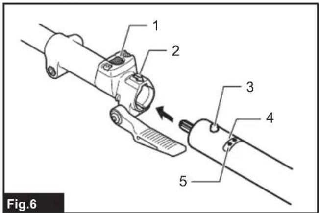

natural_image
Mechanical device diagram showing a lever mechanism with an arrow indicating motion (no text or symbols present)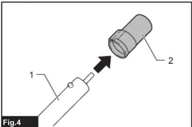
natural_image
Technical illustration of a mechanical tool being adjusted, showing a bracket and clamp assembly (no text or symbols)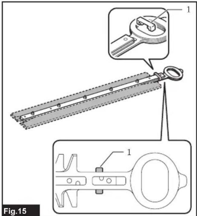
natural_image
Technical illustration of a mechanical tool being inserted into a wire, showing a clamp and clamping mechanism (no text or symbols)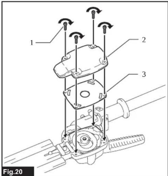
natural_image
Diagram of a tool gripping a hatched material, with no visible text or symbols
natural_image
Diagram of a mechanical tool interacting with a textured surface, showing directional arrows (no text or symbols)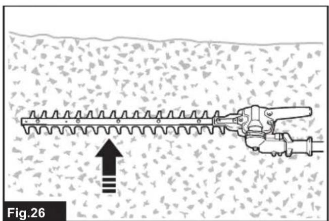
natural_image
Diagram of a hairpin in a grooved area with an upward arrow indicating force or direction (no text or symbols)
natural_image
Technical illustration of a mechanical tool with gear-like structure and an arrow indicating direction (no text or symbols)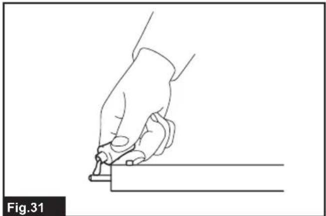
natural_image
Line drawing of a hand holding a tool, poised to write on a rectangular object (no text or symbols)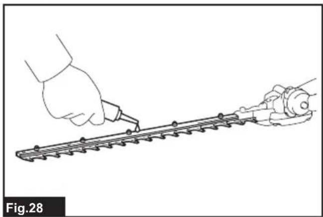
natural_image
Illustration of a hand using a tool to trim a metal strip, no text or symbols present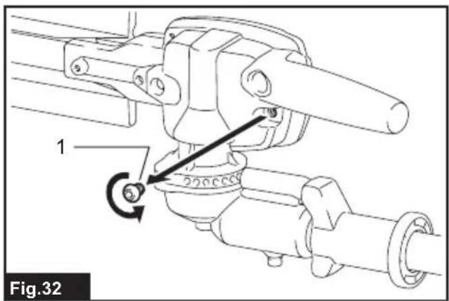

natural_image
Line drawing of a hand using a tool to adjust a mechanical part on a rack (no text or symbols)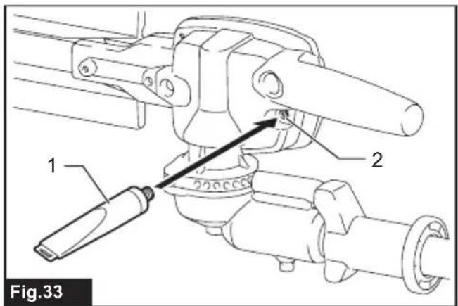
natural_image
Diagram of a mechanical component being inserted into a cylindrical housing, showing a force direction (no text or symbols)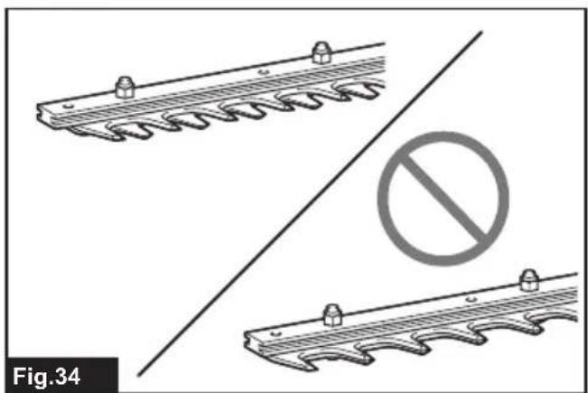
natural_image
Technical illustration showing two mechanical components with a diagonal line and a prohibition symbol (no text or labels)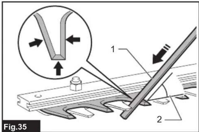
natural_image
Illustration of a hand using a tool to cut or mark a mechanical component on a base plate (no text or symbols)SPECIFICATIONS
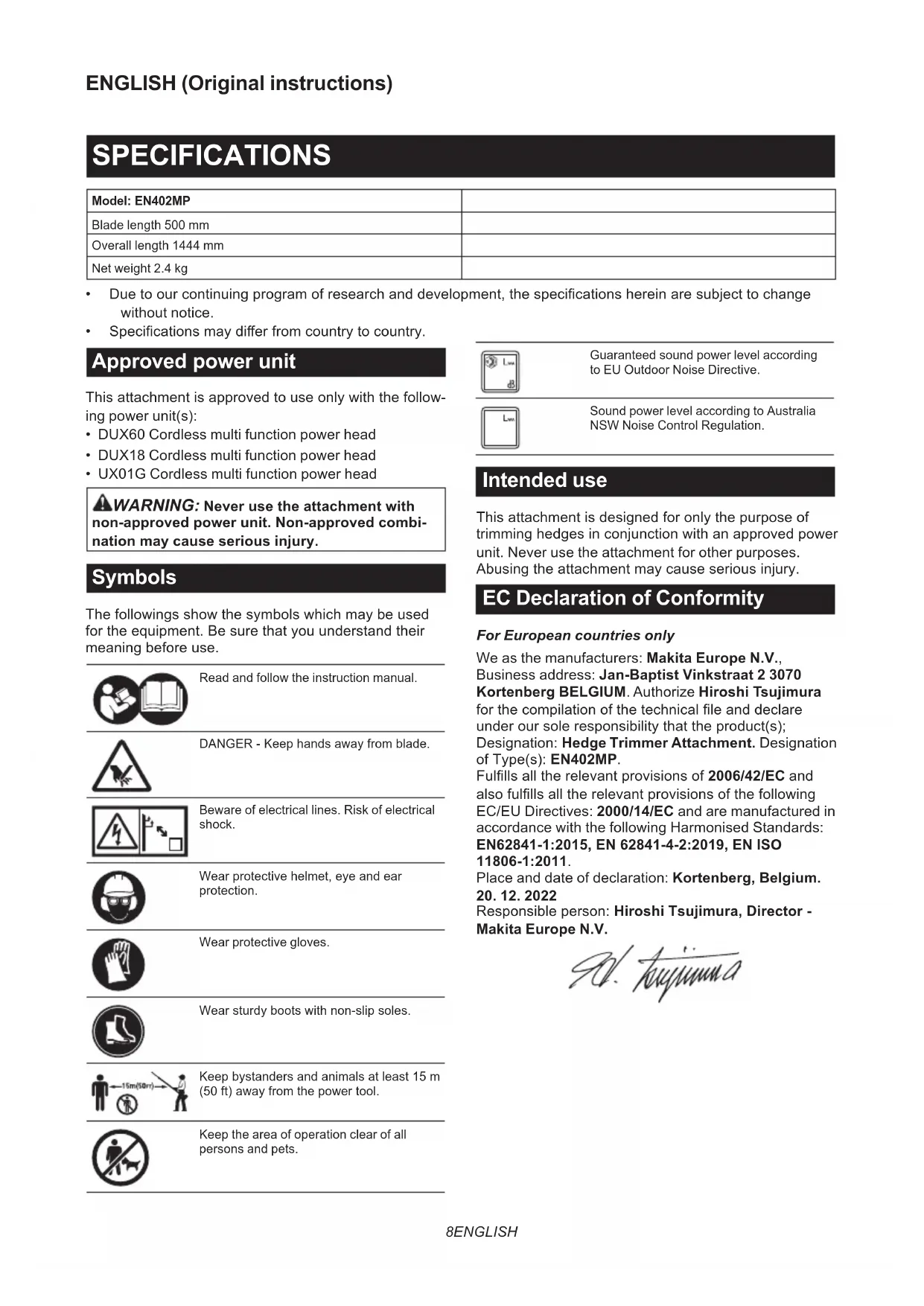
| Model: EN402MP | |
| Blade length 500 mm | |
| Overall length 1444 mm | |
| Net weight 2.4 kg |
- Due to our continuing program of research and development, the specifications herein are subject to change without notice.
• Specifications may differ from country to country.
Approved power unit
This attachment is approved to use only with the following power unit(s):
• DUX60 Cordless multi function power head
• DUX18 Cordless multi function power head
- UX01G Cordless multi function power head
WARNING: Never use the attachment with non-approved power unit. Non-approved combination may cause serious injury.
Symbols
The followings show the symbols which may be used for the equipment. Be sure that you understand their meaning before use.

Read and follow the instruction manual.

DANGER - Keep hands away from blade.
Beware of electrical lines. Risk of electrical shock.

Wear protective helmet, eye and ear protection.

Wear protective gloves.

Wear sturdy boots with non-slip soles.
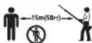
Keep bystanders and animals at least 15 m (50 ft) away from the power tool.

Keep the area of operation clear of all persons and pets.

Guaranteed sound power level according to EU Outdoor Noise Directive.

Sound power level according to Australia NSW Noise Control Regulation.
Intended use
This attachment is designed for only the purpose of trimming hedges in conjunction with an approved power unit. Never use the attachment for other purposes. Abusing the attachment may cause serious injury.
EC Declaration of Conformity
For European countries only
We as the manufacturers: Makita Europe N.V.,
Business address: Jan-Baptist Vinkstraat 2 3070
Kortenberg BELGIUM. Authorize Hiroshi Tsujimura for the compilation of the technical file and declare under our sole responsibility that the product(s);
Designation: Hedge Trimmer Attachment. Designation of Type(s): EN402MP.
Fulfills all the relevant provisions of 2006/42/EC and also fulfills all the relevant provisions of the following EC/EU Directives: 2000/14/EC and are manufactured in accordance with the following Harmonised Standards:
EN62841-1:2015, EN 62841-4-2:2019, EN ISO 11806-1:2011.
Place and date of declaration: Kortenberg, Belgium. 20. 12. 2022
Responsible person: Hiroshi Tsujimura, Director - Makita Europe N.V.
- hyuunna
Declaration of Conformity (For UK)
For UK only
We as the manufacturers: Makita Europe N.V., Business address: Jan-Baptist Vinkstraat 2 3070 Kortenberg BELGIUM. Authorize Hiroshi Tsujimura for the compilation of the technical file and declare under our sole responsibility that the product(s); Designation: Hedge Trimmer Attachment. Designation of Type(s): EN402MP.
Fulfills all the relevant provisions of S.I. 2008/1597 (as amended) and also fulfills all the relevant provisions of the following UK Regulations: S.I. 2001/1701 (as amended) and are manufactured in accordance with the following Designated Standards: EN62841-1:2015, EN 62841-4-2:2019, EN ISO 11806-1:2011.
Place and date of declaration: Kortenberg, Belgium. 20. 12. 2022
Responsible person: Hiroshi Tsujimura, Director - Makita Europe N.V.
Importer: Makita (UK) Limited, Michigan Drive, Tongwell, Milton Keynes, Buckinghamshire, MK15 8JD, UK

SAFETY WARNINGS
Cordless Pole Hedge Trimmer Safety Warnings
- Keep all parts of the body away from the blade. Do not remove cut material or hold material to be cut when blades are moving. Blades continue to move after the switch is turned off. A moment of inattention while operating the hedge trimmer may result in serious personal injury.
- Carry the hedge trimmer by the handle with the blade stopped and taking care not to operate any power switch. Proper carrying of the hedge trimmer will decrease the risk of inadvertent starting and resultant personal injury from the blades.
- When transporting or storing the hedge trimmer, always fit the blade cover. Proper handling of the hedge trimmer will decrease the risk of personal injury from the blades.
- When clearing jammed material or servicing the unit, make sure all power switches are off and the battery pack is removed or disconnected. Unexpected actuation of the hedge trimmer while clearing jammed material or servicing may result in serious personal injury.
-
Hold the hedge trimmer by insulated gripping surfaces only, because the blade may contact hidden wiring. Blades contacting a "live" wire may make exposed metal parts of the hedge trimmer "live" and could give the operator an electric shock.
-
Keep all power cords and cables away from cutting area. Power cords or cables may be hidden in hedges or bushes and can be accidentally cut by the blade.
- Do not use the hedge trimmer in bad weather conditions, especially when there is a risk of lightning. This decreases the risk of being struck by lightning.
- To reduce the risk of electrocution, never use the pole hedge trimmer near any electrical power lines. Contact with or use near power lines may cause serious injury or electric shock resulting in death.
- Always use two hands when operating the pole hedge trimmer. Hold the pole hedge trimmer with both hands to avoid loss of control.
- Always use head protection when operating the pole hedge trimmer overhead. Falling debris can result in serious personal injury.
Additional Safety Instructions
Preparation
- THIS HEDGE TRIMMER CAN CAUSE SERIOUS INJURIES. Read the instructions carefully for the correct handling, preparation, maintenance, starting and stopping of the tool. Become familiar with all controls and the proper use of the tool.
- Check the hedges and bushes for foreign objects, such as wire fences or hidden wiring before operating the tool.
- The tool must not be used by children or young persons under 18 years of age. Young persons over 16 years of age may be exempted from this restriction if they are undergoing training under the supervision of an expert.
- In the event of an emergency, switch off the tool and remove the battery cartridge immediately.
- DANGER - Keep hands away from blade. Contact with blade will result in serious personal injury.
- First-time users should have an experienced user show them how to use the tool.
- Before operation, examine the work area for wire fences, stones, or other solid objects. They can damage the blades.
- Use the tool only if you are in good physical condition. If you are tired, your attention will be reduced. Be especially careful at the end of a working day. Perform all work calmly and carefully. The user is responsible for all damages to third parties.
- Before starting work, check to make sure that the tool is in good and safe working order. Ensure guards are fitted properly. The tool must not be used unless fully assembled.
- Avoid dangerous environment. Don't use the tool in damp or wet locations or expose it to rain. Water entering the tool will increase the risk of electric shock.
Personal protective equipment
- Work gloves of stout leather are part of the basic equipment of the tool and must always be worn when working with it. Also wear sturdy shoes with anti-skid soles.
- Wear ear protection such as ear muffs to prevent hearing loss.
- Wear protective goggles, safety helmet and protective gloves to protect yourself from flying debris or falling objects.
- When touching blades or adjusting the blade angle, wear protective gloves. Blades can cut bare hands severely.
Operation
- Always use two hands to operate the tool. Using one hand could cause loss of control and result in serious personal injury.
- While operating the tool, always ensure that the operating position is safe and secure. Overreaching with the tool, particularly from a ladder, is extremely dangerous. Do not work from anything wobbly or infirm.
- Do not simultaneously wear multiple belt harnesses and/or shoulder harnesses when operating the tool.
- During operation, keep bystanders or animals at least 15 m away from the tool. Stop the tool as soon as someone approaches.
-
If cutting tool strikes any object or the tool starts making unusual noise or vibration, switch off the tool and remove the battery cartridge immediately and allow the tool to stop. And then take the following steps:
-
inspect for damage
-
check for, and tighten, any loose parts
• have any damaged parts replaced or repaired with genuine spare parts. -
Only use the tool for its intended purpose. Do not use the tool for any other purpose.
-
Switch off the tool and remove the battery cartridge before:
-
cleaning or when clearing a blockage,
- checking, carrying out maintenance or working on the tool,
-
adjusting the working position of the shear blades,
• leaving the tool unattended. -
Ensure that the tool is correctly located in a designated working position before starting the tool.
- Do not operate the tool with a damaged or excessively worn shear blades.
- Always be aware of your surroundings and stay alert for possible hazards of which you may not be aware due to the noise of the tool.
- Be careful not to accidentally contact a metal fence or other hard objects during operation. The blade will break and may cause serious injury.
-
Avoid unintentional starting. Do not carry the tool when the battery cartridge is installed and with finger on the switch. Make sure that the switch is off when installing the battery cartridge.
-
Do not grasp the exposed cutting blades or cutting edges when picking up or holding the tool.
- Do not force the tool. It will do the job better and with less likelihood of a risk of injury at the rate for which it was designed.
- Do not use the tool in the rain or in wet or very damp conditions. The electric motor is not waterproof.
- Hold the tool firmly when using the tool.
- Do not operate the tool at no-load unnecessarily.
- Before checking the shear blades, taking care of faults, or removing foreign objects caught in the shear blades, always switch off the tool and remove the battery cartridge.
- Never point the shear blades to yourself or others.
- If the blades stop moving due to the stuck of foreign objects between the blades during operation, switch off the tool and remove the battery cartridge, and then remove the foreign objects using tools such as pliers. Removing the foreign objects by hand may cause an injury for the reason that the blades may move in reaction to removing the foreign objects.
- When attaching or removing the blade cover, be careful not to injure your hands.
Electrical and battery safety
- Avoid dangerous environment. Don't use the tool in damp or wet locations or expose it to rain. Water entering the tool will increase the risk of electric shock.
- Do not dispose of the battery(ies) in a fire. The cell may explode. Check with local codes for possible special disposal instructions.
- Do not open or mutilate the battery(ies). Released electrolyte is corrosive and may cause damage to the eyes or skin. It may be toxic if swallowed.
- Do not charge battery in rain, or in wet locations.
- Do not charge the battery outdoors.
- Do not handle charger, including charger plug, and charger terminals with wet hands.
Maintenance and storage
- When the tool is stopped for servicing, inspection or storage, switch off the tool and remove the battery cartridge, and make sure all moving parts have come to a stop. Allow the tool to cool before making any inspections, adjustment, etc.
- Always allow the tool to cool down before storing.
- When not in use, attach the blade cover to the tool and store the tool indoors in dry, and high locked-up place, out of reach of children.
-
Maintain the tool with care. Keep cutting edge sharp and clean for best performance and to reduce the risk of injury. Follow instructions for lubricating and changing accessories. Keep grips dry, clean, and free from oil and grease.
-
Check damaged parts. Before further use of the tool, any part which is damaged should be carefully checked to determine that it will operate properly and perform its intended function. Check for alignment of moving parts, binding of moving parts, breakage of parts, mounting and any other condition that may affect its operation. A guard or other part that is damaged should be properly repaired or replaced by your authorized service center.
- Use genuine spare parts only.
- When moving the tool to another location, including during work, always remove the battery cartridge and put the blade cover on the shear blades. Never carry or transport the tool with the blades running. Never grasp the blades with your hands.
- Clean the tool and especially the shear blades after use, and before putting the tool into storage for extended periods. Lightly oil the shear blades and put on the blade cover.
- Do not dispose of the battery(ies) in a fire. The cell may explode. Check with local codes for possible special disposal instructions.
- Do not open or mutilate the battery(ies). Released electrolyte is corrosive and may cause damage to the eyes or skin. It may be toxic if swallowed.
- Do not charge battery in rain, or in wet locations.
SAVE THESE INSTRUCTIONS.
⚠ WARNING: DO NOT let comfort or familiarity with product (gained from repeated use) replace strict adherence to safety rules for the subject product. MISUSE or failure to follow the safety rules stated in this instruction manual may cause serious personal injury.
PARTS DESCRIPTION
▶ Fig.1: 1. Blade cover 2. Angle adjustment handle 3. Cap 4. Shear blades 5. Slide lever 6. Front grip
ASSEMBLY
WARNING: Before assembling or adjusting the equipment, switch off the motor and remove the battery cartridge. Otherwise, the machine may start unintentionally and result in an injury.
WARNING: When assembling or adjusting the equipment, always put it down. Assembling or adjusting the equipment in an upright position may result in serious injury.
WARNING: Follow the warnings and precautions in the chapter "SAFETY WARNINGS" and the instruction manual of the power unit.
Assembling the attachment
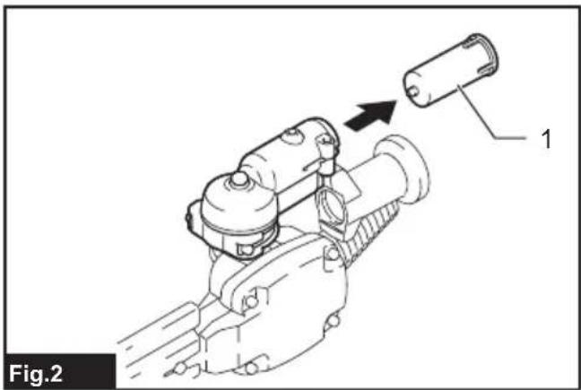
- Remove the cap from the attachment.
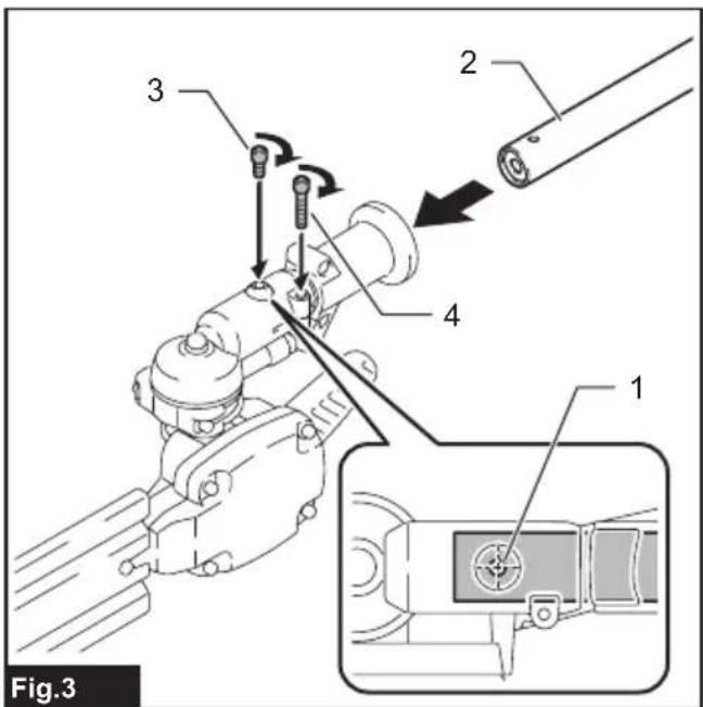
▶ Fig.2: 1. Cap - Insert the pipe into the attachment so that the hole on the pipe is aligned with the hole on the attachment. Securely tighten the short bolt first, and then tighten the long bolt to fix the pipe.
▶ Fig.3: 1. Hole 2. Pipe 3. Bolt (short) 4. Bolt (long)
NOTE: When tightening the bolts, apply 4.0 - 6.0 N•m as tightening torque.
Mounting the attachment pipe
CAUTION: Always check that the attachment pipe is secured after installation. Improper installation may cause the attachment falling off from the power unit and cause personal injury.
Mount the attachment pipe to the power unit.
- Remove the cap from the end of the pipe.
▶ Fig.4: 1. Pipe 2. Cap
NOTICE: Do not dispose of the cap since the cap is necessary for storing the attachment.
- Turn the lever toward the attachment.
▶ Fig.5: 1. Lever - Align the pin with the arrow mark on the power unit. Insert the pipe until the release button pops up.
Make sure that the position line is on the tip of the arrow mark on the power unit, and the arrow mark on the power unit and the arrow mark on the pipe are facing each other.
▶ Fig.6: 1. Release button 2. Arrow mark on the power unit 3. Pin 4. Position line 5. Arrow mark on the pipe
4. Turn the lever toward the power unit.
▶ Fig.7: 1. Lever
Make sure that the surface of the lever is parallel to the pipe.
NOTICE: Do not tighten the lever without the attachment pipe inserted. Otherwise the lever may tighten the entrance of the drive shaft too much and damage it.
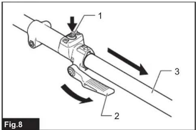
To remove the pipe, turn the lever toward the attachment and pull the pipe out while pressing down the release button.
▶ Fig.8: 1. Release button 2. Lever 3. Pipe
Installing or removing the shear blades
CAUTION: When replacing the shear blades, always wear gloves so that your hands do not directly contact the blades.
CAUTION: Attach the blade cover before removing or installing the shear blades.
NOTICE: When replacing the shear blades, do not wipe off grease from the crank.
NOTE: Before installing or removing the shear blades, unfold the attachment so that the attachment is straight to the pipe.
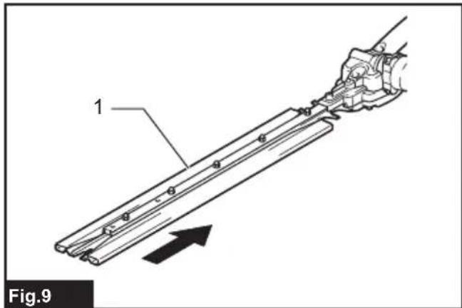
- Attach the blade cover to the shear blades.
▶ Fig.9: 1. Blade cover
-
Place the attachment upside down.
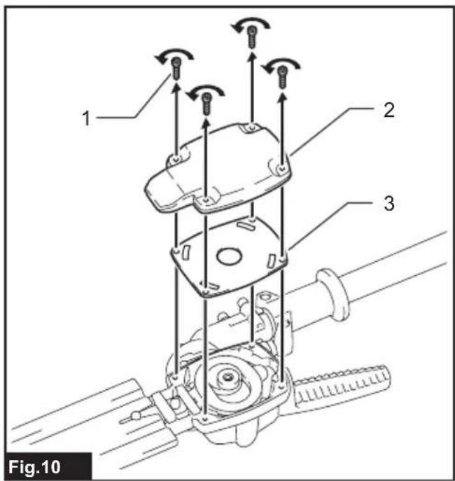
-
Remove 4 bolts with the hex wrench and remove cover and plate (large).
▶ Fig.10: 1. Bolt 2. Cover 3. Plate (large)
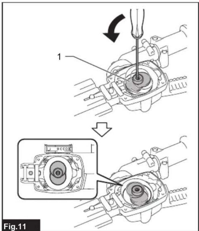
- Turn the crank with the slotted screwdriver so that the crank is positioned in the direction as shown in the figure.
▶ Fig.11: 1. Crank
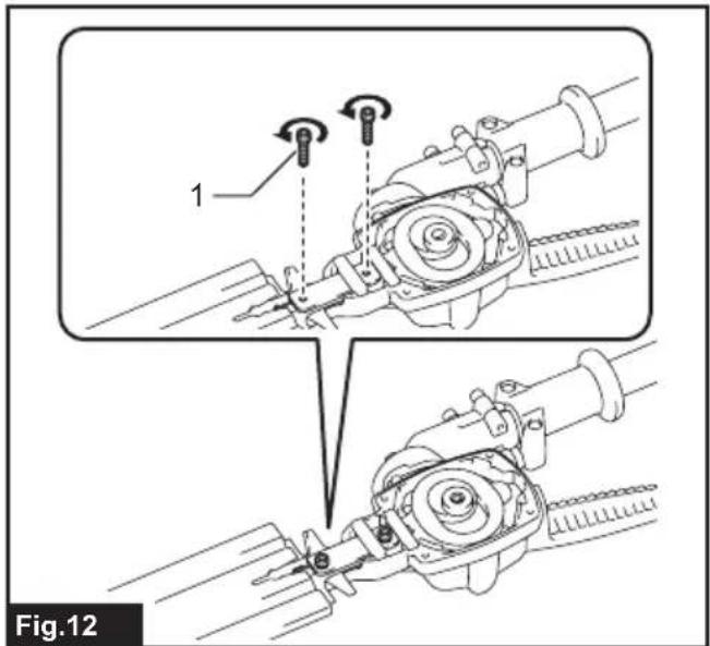
- Remove 2 bolts.
▶ Fig.12: 1. Bolt
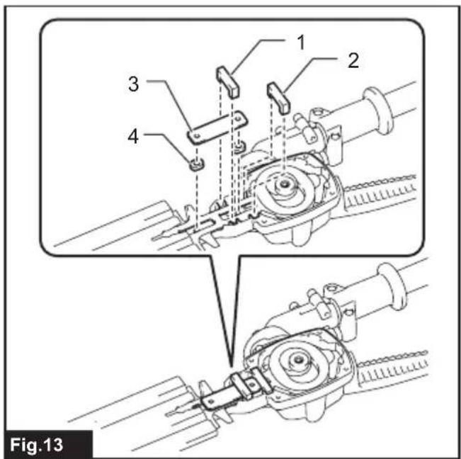
- Remove the felt pad (short), felt pad (long), plate (small), and sleeves.
▶ Fig.13: 1. Felt pad (short) 2. Felt pad (long) 3. Plate (small) 4. Sleeve
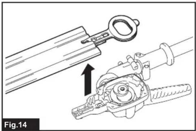
- Remove the shear blades from the attachment.
▶ Fig.14
-
Remove the blade cover, and then attach it to the new shear blades.
-
Remove the dust guard from the shear blades, and then attach it in the position shown in the figure on the new shear blades.
▶ Fig.15: 1. Dust guard
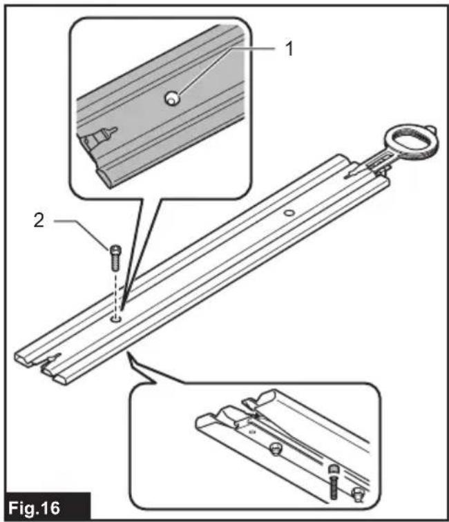
- Insert the bolt removed in step 5 into the hole on the shear blades through the hole on the blade cover.
▶ Fig.16: 1. Hole 2. Bolt
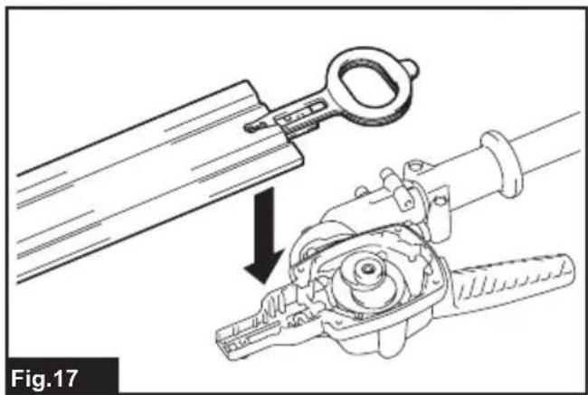
- Apply a small amount of grease to the periphery of the crank. Attach the shear blades to the attachment.
▶ Fig.17
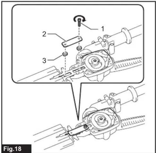
- Attach the sleeves, plate (small) to the shear blades, and then tighten the bolt.
▶ Fig.18: 1. Bolt 2. Plate (small) 3. Sleeve
-
Remove the bolt inserted into the hole on the shear blades in step 10, and then tighten it to fix the shear blades.
-
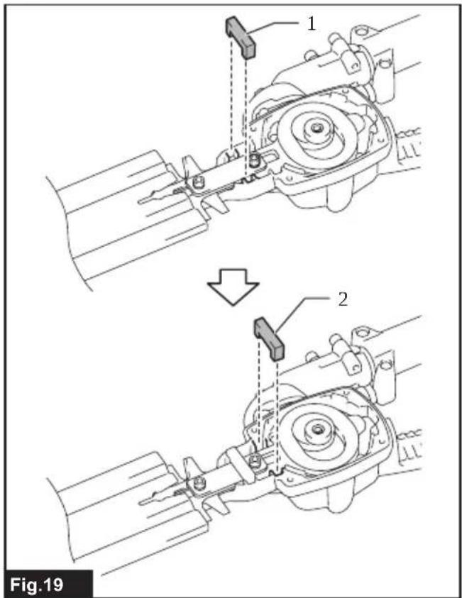
Attach the felt pad (short) and felt pad (long).
▶ Fig.19: 1. Felt pad (short) 2. Felt pad (long)
- Attach the plate (large) and cover, and then tighten 4 bolts.
▶ Fig.20: 1. Bolt 2. Cover 3. Plate (large)
NOTICE: If the shear blades do not operate properly, the blades are not engaging the crank properly. Remove the blades and install them again.
NOTICE: If the parts other than the shear blades such as the crank are worn out, ask Makita Authorized Service Centers for parts replacement or repairs.
FUNCTIONAL DESCRIPTION
CAUTION: Always be sure that the tool is switched off and the battery cartridge is removed before adjusting or checking function on the tool.
Adjusting the cutting angle
⚠️ CAUTION: Always be sure that the tool is switched off before adjusting the cutting angle.
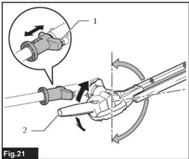
The angle of the head can be adjusted in 13 steps. To change the angle of the head, follow the steps below.
- Hold the angle adjustment handle, and then adjust the angle of the head while pulling the slide lever, and then release the slide lever.
▶ Fig.21: 1. Slide lever 2. Angle adjustment handle
- Move the head slightly until it is locked with a click.
NOTE: Make sure that the head is securely locked before operating the tool.
OPERATION
WARNING: Follow the warnings and precautions in the chapter "SAFETY WARNINGS" and the instruction manual of the power unit.
Operating the tool
WARNING: Do not use the tool near any electrical power lines. Contacting with power lines or using the tool near power lines may cause serious injury or electric shock resulting in death.
⚠ WARNING: Keep hands away from shear blades.
WARNING: Be extremely careful to maintain control of the tool at all times. Do not allow the tool to be deflected toward you or anyone in the work vicinity. Failure to keep control of the tool could result in serious injury to the bystander and the operator.
CAUTION: Avoid operating the tool in very hot weather as much as practicable. When operating the tool, be careful of your physical condition.
CAUTION: Be careful not to accidentally contact a metal fence or other hard objects while trimming. The shear blades may break and cause an injury.
CAUTION: Be careful not to allow the shear blades to contact the ground. The tool may recoil and cause an injury.
CAUTION: Overreaching with a hedge trim-mer, particularly from a ladder, is extremely dangerous. Do not work while standing on anything wobbly or infirm.
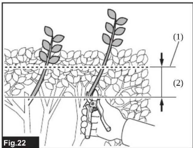
NOTICE: Do not attempt to cut branches thicker than 10 mm in diameter with the tool. Cut branches to 10 cm lower than the cutting height using branch cutters before using the tool.
▶ Fig.22: (1) Cutting height (2) 10 cm
NOTICE: Do not cut down dead trees or similar hard objects. Doing so may damage the tool.
NOTICE: Do not trim the grass or weeds while using the shear blades. The shear blades may become tangled in the grass or weeds.
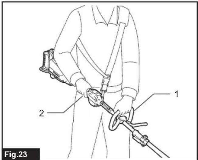
Hold the tool with both hands by holding the front handle of the power unit or the front grip of the attachment and the rear grip of the power unit.
▶ Fig.23: 1. Front handle 2. Rear grip
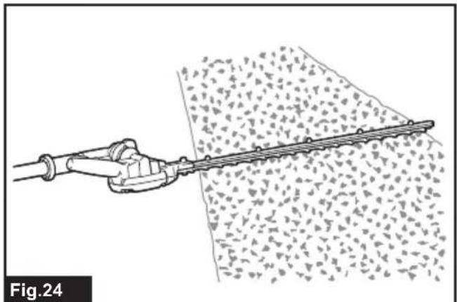
Pull the switch trigger while pressing the lock-off lever, and then move the tool forward.
▶ Fig.24
For basic operation, tilt the shear blades toward the trimming direction and move it calmly and slowly at the speed rate of 3 to 4 seconds per meter.
▶ Fig.25
To cut a hedge side evenly, cut from the bottom to top.
▶ Fig.26
When trimming to make a round shape (trimming box-wood or rhododendron, etc.), trim from the root to the top for a beautiful finish.
▶ Fig.27
MAINTENANCE
WARNING: Before inspecting or maintaining the equipment, switch off the motor and remove the battery cartridge. Otherwise, the machine may start unintentionally and result in serious injury.
WARNING: When inspecting or maintaining the equipment, always put it down. Assembling or adjusting the equipment in an upright position may result in serious injury.
WARNING: Follow the warnings and precautions in the chapter "SAFETY WARNINGS" and the instruction manual of the power unit.
⚠️CAUTION: Wear gloves when performing the inspection or maintenance.
NOTICE: Never use gasoline, benzine, thinner, alcohol or the like. Discoloration, deformation or cracks may result.
To maintain product SAFETY and RELIABILITY, repairs, any other maintenance or adjustment should be performed by Makita Authorized or Factory Service Centers, always using Makita replacement parts.
Cleaning the tool
Clean the tool by wiping off dust with a dry cloth or one dipped in soapy water and wrung out.
NOTICE: Never use gasoline, benzine, thinner, alcohol or the like. Discoloration, deformation or cracks may result.
Shear blade maintenance
Before the operation or once per hour during operation, apply low-viscosity oil (machine oil, or spray-type lubricating oil) to the shear blades.
▶ Fig.28
After operation, remove dust from both sides of the shear blades with a wired brush, wipe it off with a cloth and then apply low-viscosity oil (machine oil, or spray-type lubricating oil) to the shear blades.
▶ Fig.29
NOTICE: Do not wash the shear blades in water. Doing so may cause rust or damage to the tool.
NOTICE: Dirt and corrosion cause excessive blade friction and shorten the operating time per battery charge.
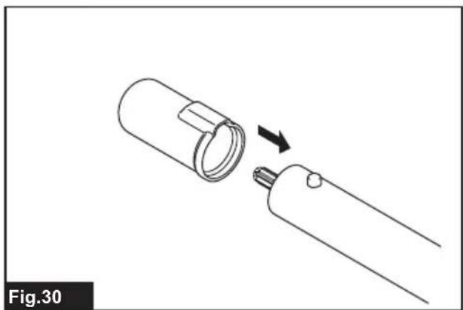
Storage
Attach the blade cover to the shear blades so that the blades are not exposed. Store the tool out of the reach of children. Store the tool in a place not exposed to moisture or rain. When storing the attachment separated from the power unit, put the cap onto the end of the pipe.
▶ Fig.30
Lubricating moving parts
NOTICE: Follow the instruction of the frequency and amount of grease supplied. Otherwise insufficient lubrication may damage moving parts.
Drive axle:
Apply grease (Makita grease N No.2 or equivalent) every 30 hours of operation.
▶ Fig.31
NOTE: Genuine Makita grease may be purchased from your local Makita dealer.
Grease lubrication
Interval of lubrication: Every 25 operating hours
- Remove the bolt from the hole for lubrication.
▶ Fig.32: 1. Bolt
- Remove the cap from the grease vessel. Align the outlet of the grease vessel with the hole on the cover, and then turn the grease vessel to attach the outlet of the grease vessel into the hole.
▶ Fig.33: 1. Grease vessel 2. Hole
-
Apply the grease to the tool (Approximately 3 g as a guide).
-
Remove the grease vessel.
-
Tighten the bolt.
Grinding the shear blades
NOTICE: If the shear blades have considerably deformed by grinding, replace the shear blades with new ones.
- Install the battery cartridge to the tool.
- Turn on and start the tool so that the upper blade and lower blade are positioned alternately.
▶ Fig.34 - Turn off the tool and remove the battery cartridge from the tool.
- Set the angle of a file to 45irc , and grind the upper blade from 3 directions with the file.
▶ Fig.35: (1) File (2) 45°
CAUTION: Before grinding the shear blades, make sure that the tool is switched off and the battery cartridge is removed from the tool.
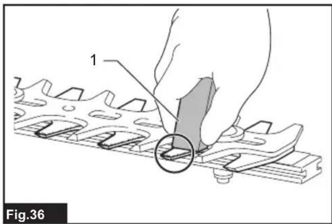
- Place the tool upside down, and then remove the burrs from the shear blades with the dressing stone.
▶ Fig.36: 1. Dressing stone - Set the angle of the file to 45irc , and grind the lower blade from 3 directions with the file.
- Return the tool to normal position, and then remove the burrs from the shear blades with the dressing stone.
TROUBLESHOOTING
Before asking for repairs, conduct your own inspection first. If you find a problem that is not explained in the manual, do not attempt to dismantle the tool. Instead, ask Makita Authorized Service Centers, always using Makita replacement parts for repairs.
| State of abnormality Probable cause | (malfunction) Remedy | |
| Motor does not start. - Refer to the instruction manual of the power unit. | ||
| Motor stops soon. - Refer to the instruction manual of the power unit. | ||
| Motor speed does not increase. - Refer to the instruction manual of the power unit. | ||
| Shear blades do not move: → stop the machine immediately! | Foreign objects are caught between the shear blades. | Switch off the tool and remove the battery cartridge, and then remove the foreign objects using tools such as pliers. |
| The drive system does not work correctly. | Ask your local authorized service center for repair. | |
| Abnormal vibration: → stop the machine immediately! | Shear blades are broken, bent or worn. | Replace the shear blades. |
| The drive system does not work correctly. | Ask your local authorized service center for repair. | |
| Shear blades and motor cannot stop: → Remove the battery immediately! | Electric malfunction. Remove the battery | and ask your local authorized service center for repair. |
OPTIONAL ACCESSORIES
⚠️CAUTION: These accessories or attachments are recommended for use with your Makita machine specified in this manual. The use of any other accessories or attachments might present a risk of injury to persons. Only use accessory or attachment for its stated purpose.
If you need any assistance for more details regarding these accessories, ask your local Makita Service Center.
• Shear blade assembly
- Grease vessel
• Makita genuine battery and charger
NOTE: Some items in the list may be included in the product package as standard accessories. They may differ from country to country.
SPÉCIFICATIONS
▶ Fig.4: 1. Tuyau 2. Capuchon
▶ Abb.4: 1. Rohr 2. Kappe
▶ Abb.36: 1. Abziehstein
VEILIGHEIDSWAAR- SCHUWINGEN
OPTIONELE ACCESSOIRES
Persona responsible: Hiroshi Tsujimura, Director - Makita Europe N.V.
- hyuunna
▶ Fig.20: 1. Bolt 2. Dæksel 3. Plade (stor)
▶ Abra16: 1. Furat 2. Csavar
TIETO POKYNY USCHOVAJTE.
TYTO POKYNY USCHOVEJTE.
VOLITELNÉ PŘÍSLUŠENSTVÍ
▶ Fig.11: 1. Pârghie
- Scoateți 2 bolțuri.
▶ Fig.12: 1. Bolt
3-11-8, Sumiyoshi-cho,
Anjo, Aichi 446-8502 Japan


- Approved power unit
- Symbols
- Intended use
- EC Declaration of Conformity
- For European countries only
- Declaration of Conformity (For UK)
- For UK only
- SAFETY WARNINGS
- Cordless Pole Hedge Trimmer Safety Warnings
- Additional Safety Instructions
- Preparation
- Personal protective equipment
- Operation
- Electrical and battery safety
- Maintenance and storage
- SAVE THESE INSTRUCTIONS.
- PARTS DESCRIPTION
- ASSEMBLY
- Assembling the attachment
- Mounting the attachment pipe
- Installing or removing the shear blades
- FUNCTIONAL DESCRIPTION
- Adjusting the cutting angle
- Operating the tool
- MAINTENANCE
- Cleaning the tool
- Shear blade maintenance
- Storage
- Lubricating moving parts
- Drive axle:
- Grease lubrication
- Grinding the shear blades
- TROUBLESHOOTING
- OPTIONAL ACCESSORIES
- VEILIGHEIDSWAAR- SCHUWINGEN
- OPTIONELE ACCESSOIRES
- TIETO POKYNY USCHOVAJTE.
- TYTO POKYNY USCHOVEJTE.
- VOLITELNÉ PŘÍSLUŠENSTVÍ
Brand : MAKITA
Model : EN402MP
Category : Hedge Trimmers