
Viper AS430 - Sweeper NILFISK - Free user manual and instructions
Find the device manual for free Viper AS430 NILFISK in PDF.
| Product Type | Ride-on sweeper-scrubber |
| Brand | Nilfisk |
| Model | Viper AS430 |
| Working width | 430 mm |
| Squeegee width | 730 mm |
| Brush diameter | 430 mm |
| Brush speed | 150 rpm |
| Brush motor power | 550 W |
| Suction motor power | 350 W |
| Solution tank capacity | 40 L |
| Recovery tank capacity | 40 L |
| Dimensions (L x W x H) | 1060 x 480 x 980 mm |
| Weight (with batteries and empty tanks) | 112 kg |
| Gross weight ready for use | 152 kg |
| Power supply | 24 V DC (2 batteries 12 V 85 Ah AGM) |
| Runtime | Approximately 2-3 hours depending on load |
| Maximum operating slope | 2 % |
| Sound pressure level | 70 dB(A) |
| Operating temperature | 0 to 40 °C |
| Air humidity | 30% to 105% |
| Squeegee tilt adjustment | Adjustment knob |
| Water flow adjustment | Quarter-turn valve |
| Maintenance | Regular cleaning of squeegee, brush, filters |
| Disposal | Remove battery and electrical components, recycle according to regulations |
Frequently Asked Questions - Viper AS430 NILFISK
User questions about Viper AS430 NILFISK
0 question about this device. Answer the ones you know or ask your own.
Ask a new question about this device
Download the instructions for your Sweeper in PDF format for free! Find your manual Viper AS430 - NILFISK and take your electronic device back in hand. On this page are published all the documents necessary for the use of your device. Viper AS430 by NILFISK.
USER MANUAL Viper AS430 NILFISK
SЯruЦЦOr UsOr MTBuТГ
HS430N & HS510N
CE
natural_image
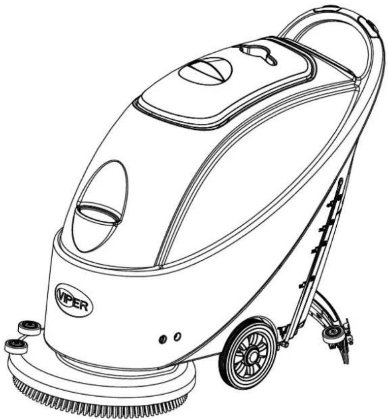
Line drawing of a Viper cleaning service robot with wheels and control panel (no text or symbols)
EU / UE / EL / EC / EE / ES / EÚ / AB / EG
Declaration of Conformity
Prohlášení o shodě
FC - Floor Scrubber/Sweeper - Battery
Charging mode: 100-240V; Working mode 24V DC, IP24

We, Nilfisk hereby declare under our sole responsibility, that the above mentioned product(s) is/are in conformity with the following directives and standards.

Authorized signatory: Pierre Mikaelsson, Executive Vice President, Global Products & Services, Nilfisk NLT
Dec 1, 2021

UK Declaration of Conformity
We,
Nilfisk Ltd
Nilfisk House, Bowerbank Way Gilwilly Industrial Estate
Penrith Cumbria
CA11 9BQ UK
Hereby declare under our sole responsibility that the
Products: FC - Floor Scrubber/Sweeper - Battery
Description: Charging mode: 100-240V; Working mode 24V DC, IP24
Type: AS430B, AS510B
Are in compliance with the following standards:
EN 60335-1:2012+A11:2014+A13:2017+A1:2019+A14:2019+A2:2019
EN 60335-2-72:2012
EN 55014-1:2021
EN 55014-2:2021
EN 61000-3-2:2019+A1:2021
EN 61000-3-3:2013+A1:2019
Following the provisions of:
Supply of Machinery (Safety) Regulations 2008/1597
Electromagnetic Compatibility Regulations 2016/1091
Penrith, 1-12-2021
Stewart Dennett
GM/MD
TABLE OF CONTENTS
| ENGLISH | USER MANUAL.... | 1-19 |
| DEUTSCH | BETRIEBSANLEITUNG.... | 20-40 |
| FRANÇAÏS | MANUEL UTILISATEUR.... | 41-59 |
| NEDERLANDS | GEBRUIKERS HANDLEIDING.... | 60-79 |
| ITALIANO | MANUALE D'USO.... | 80-99 |
| ESPAÑOL | ISTRUZIONI PER L'USO.... | 100-120 |
| PORTUGUÈS | MANUAL DO UTILIZADOR.... | 121-140 |
| ΕΛΛΗΝΙΚΑ | ΕΓΧΕΙΡΙΔΙΟ ΧΡΗΣΤΗ.... | 141-161 |
| TÜRKÇE | KULLANIM KILAVUZU.... | 162-181 |
| ČESKÝ | UŽIVATELSKÝ MANUÁL.... | 182-201 |
| Slovenský | Návod na obsluhu.... | 202-221 |
| POLSKI | INSTRUKCJA OBSŁUGI.... | 222-241 |
| MAGYAR | FELHASZNÁLÓI KÉZIKÖNYV.... | 242-261 |
| ROMÂNĂ | MANUALUL UTILIZATORULUI.... | 262-281 |
| РУССКИЙ | НСТРУКЦИЯ ПО ПРИМЕНЕНИЮ.... | 282-302 |
| БЪЛГАРСКИ | РЪКОВОДСТВО НА ПОТРЕБИТЕЛЯ.... | 303-322 |
| SLOVENŠČINA | NAVODILA ZA UPORABO.... | 323-342 |
| DANSK | BRUGERMANUAL.... | 343-362 |
| SVENSKA | BRUKSANVISNING.... | 363-382 |
| NORSK | BRUKERHÅNDBOK.... | 383-402 |
| SUOMI | KÄYTTÄJÄN OPAS.... | 403-422 |
| HRVATSKI | KORISNIČKI PRIRUČNIK.... | 423-442 |
| EESTI | KASUTUSJUHEND.... | 443-461 |
| LATVIEŠ | LIETOTÄJA.... | 462-480 |
| LIETUVIŠKAI | NAUDOTOJO INSTRUKCIJA.... | 481-499 |
THNT'A OF IONTANTS
ΔNTROKUITΔON 2
MANUAL CONTENTS 2
PURPOSE....2
SPARE PARTS AND MAINTENANCE....2
CHANGES AND IMPROVEMENTS ....2
SCOPE OF APPLICATION....2
IDENTIFICATION DATA....2
UNPACKING/TRANSPORT....2
GENERAL SAFETY GUIDES ....3
TECHNICAL DATA....4
MHIPΔNÄ KASIRΔPTΔON 4
MACHINE STRUCTURE ....4
CONTROL PANEL ....5
DISPLAY WINDOW OF CHARGER INDICATION LIGHT 6
XUΔKA ΓOR USA....6
INSTALLING AND SETTING THE BATTERY OF THE NEW MACHINE 6
INSTALLING BATTERY AND SETTING BATTERY TYPE(WET OR GEL/AGM) 7
BEFORE MACHINE START-UP 9
INSTALLING AND UNLOADING THE BRUSH / PAD-HOLDER....9
ADJUSTING THE BALANCE OF THE SQUEEGEE....10
REGULATING THE VOLUME OF WATER FLOW 10
MACHINE START AND STOP 11
MACHINE OPERATION (SCRUBBING AND DRYING).... 11
TANK EMPTYING 12
AFTER USING THE MACHINE.... 13
PERIODS OF INACTIVITY....13
USING FOR THE FIRST TIME....13
MHΔNT'ANHNIA HNK IHRA 13
SCHEDULED MAINTENANCE TABLE 14
BATTERY CHARGING....14
SQUEEGEE CLEANING ....15
SQUEEGEE BLADE CHECK AND REPLACEMENT....15
BRUSH/POLISHING PAD CLEANING 16
WATER TANK AND FLOAT FILTER MESH CLEANING 16
SOLUTION FILTER CLEANING....17
CIRCUIT FIGURE OF AS430B AND AS510B 18
TROUNTASPOOTΔNX ....19
MHIPΔNÄ KΔSPOSHT ....19
ΔNTROKUITΔON

NOTA
This manual is to provide the operator with the necessary information to use this machine properly and safely. The information includes the technical data, safety, operation, storage, maintenance and disposal of the machine. The operator and technicians with related qualifications must study this manual carefully before commencing the operation and maintenance of this machine. Please contact VIPER for any queries on the explanation of this manual or when further related information is needed.
PURPOSA
The intention of this manual is to enable the operator and qualified technicians to accomplish the maintenance of this machine.
The operator must not perform those operations that should only be performed by technicians.
VIPER will not be responsible for any damages caused by the violation of this rule.
SPHRA PHRTS HNK MHΔNTANHNIA
All necessary operation, maintenance, and repair procedures must be performed by qualified personnel or by the service centers of VIPER
Only Authorised spare parts and accessories should be used.
If service and ordering of spare parts or accessories are needed, please contact VIPER with the model number of the machine and serial numbers.
IPHNXAS HNK ΔMPROVAMANTS
VIPER makes continuous improvements on its products. VIPER reserves the right of changing and improving the machines, and also the right of deciding by itself whether the benefits brought about by the changes are applicable to the products already sold. All changes or extra accessories must be agreed by VIPER and must be performed by the company.
SIOPĂ OΓ HPPTΔΙΗΤΔΟΝ
This scrubber is used in a domestic and industrial environment, and is suitable for the cleaning of smooth and hard floors (scrubbing and waste water collection). It must be used by qualified operators and in a safe environment. This scrubber can not be used for cleaning outdoors, on carpets, and on relatively coarse floors.
ΔΚΑΝΤΔΓΔΙΗΤΔΟΝ ΚΗΤΗ
The machine model and serial number are marked on the plate (4).
This information is useful when requiring machine spare parts, Use the following table to write down the machine identification data.
MACHINE mode....
MACHINE serial number......
UNPHIΣΔNX/TRHNSPORT
Please follow carefully the instructions on the package when unpacking. On delivery, please inspect the packing and the machine to ensure no damage has been done during transport. If there is any visible damage, please keep the original form, and ask the carrier to confirm and fill out a list of damages for compensation.

— CHAITAON
WIOOB uBpTЯЛБВЕ ТВП uВГДТПБВЕ, Дг NurБВЕ АДvБВЕ tЮО АТЯЮБВО ТЯгДss ErДuВП wБтЮ stOps, pГОТsO tТЛО ЯТрО тДА TvДБП ЮБttБВЕ tЮО ДВ/ДММ swБтЯЮ rОEuГТtБВЕ tЮО wTtOr МГДw, PTrt Н БВ tЮО МБEurO ДВ tЮО rБЕЮт.
Check if the machine is equipped with the following items:
- Technical documents
- Scrubber User Manual
- On-board Charger Manual (if equipped)
- connector for Charger (if not equipped with on-board charger, it is on the specified external charger)
XANARHT SHΓΑΤΑ XUΔΚΑS
The following are special warnings and notices on potential damages (personnel and machine):

WHRNANX
- Machinen may only be operated under the guidance of this manual. Only accessories approved by VIPER should be used.
- This machine must be only used by duly trained or authorised personnel. Children or inappropriate persons must not use this machine.
- Under normal use, the battery may emit inflammable gas. The battery must be kept away from radiating, illuminating, and burning items as well as sparks. When the machine is being used, please ensure that the environment is well ventilated and is away from naked flames. When charging, please do not smoke in the vicinity of the machine.
- Please disconnect the battery prior to the performance of any maintenance/repair operations.
- Before using the on-board charger, please ensure that the values of voltage and frequency as indicated on the serial number sticker match those of the mains.
- When workingnear electrical parts, please do not wear any jewelry. Please take all precautionary measures to avoid the hair, jewelry, and loose fitting clothes from being caught by any moving parts of the machine.
- Please do not use this machine in particularly dirty areas. Do not wash the machine directly with water. Do not let the machine come in touch with corrosive liquids.
- The temperature for storage and for working environment of the machine must be between 0 - 40^ .
- The humidity of air must be between 30% - 105%.
- Please do not use the machine on a slope with a gradient of more than 2%.
- In case of fire, please use dry powder fire extinguishers. Do not use liquid fire extinguishers.
- Particular attention should be paid when the machine is transported below 0 ^0 C. The water tank and the water in the hoses may freeze and cause serious damages to the machine.
- Use brushes and pads supplied with the machine and those specified in the User Manual. Using other brushes or pads could reduce safety.
- In case of machine malfunction, please make sure that it is not caused by lack of maintenance. If it is caused by other conditions, please seek the assistance of authorised personnel or the service center.
- If it is confirmed that the spare parts must be replaced, please secure the genuine parts from authorised dealers or agents.
- In order to ensure the safe and proper operation of the machine, please let authorised personnel or the service center perform the scheduled maintenance according to the maintenance schedules in the related sections of the manual.
- This machine must be properly disposed of because there may exist poisonous and hazardous matters (batteries, etc.), and these matters must be disposed of by special centers in accordance with related laws and regulations (please refer to machine disposal section).
TAIPNΔIHT KHTH
| Model AS430B AS510B | ||
| Machine Height 980mm | ||
| Solution tank capacity 40 litre | ||
| Recovery tank capacity 40 litre | ||
| Diameter of transport wheel 200mm | ||
| Diameter of guide wheel 76mm | ||
| Power of vacuum system motor 350w | ||
| Maximum gradient when working | 2%(Max) | |
| Sound pressure level at workstation | 70dB(A) β3dB(A) | |
| Standard batteries (2×12V) 24V 85Ah AGM | (2×12V) 24V 105Ah AGM | |
| Battery compartment size (W x L x H) 340 x 330 x 260mm(Max) | ||
| Vacuum system circuit capacity | 1200 mm H2O | |
| Cleaning width | 430mm 510mm | |
| Squeegee width | 730mm 790mm | |
| machine maximum length | 1060mm | 1100mm |
| Machine width without squeegee | 480mm 540mm | |
| Brush diameter | 430mm 510mm | |
| Weight with batteries and with empty tanks | 112kg | 128kg |
| Gross weight of the machine ready for use | 152kg | 168kg |
| Brush motor power | 550W | 560W |
| Brush speed | 150rpm | |
| Brush /pad-holder Maximum pressure | 30kg (Max) | 35kg(Max) |
| Packing size (Lx W x H) | 1200 x 610 x 1170mm | |
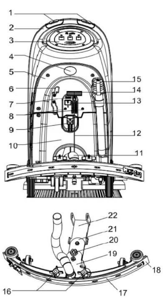
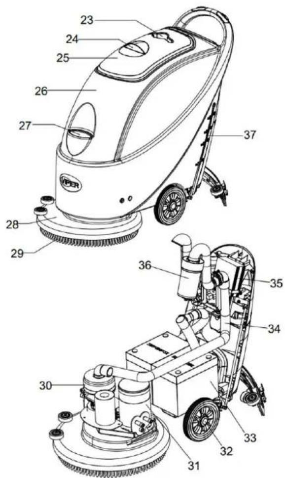
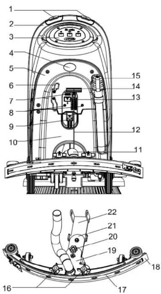
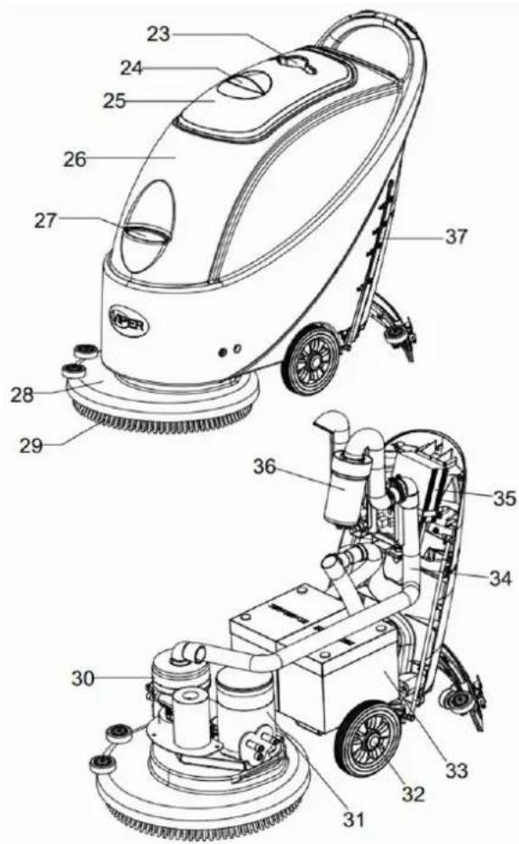
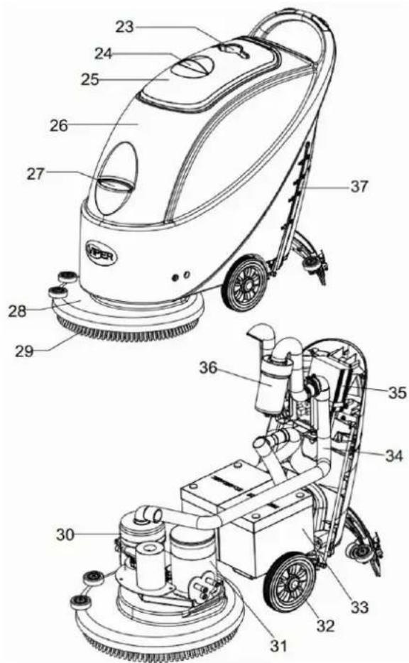
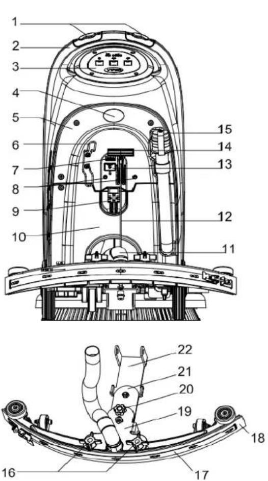
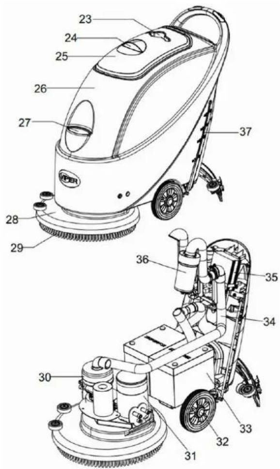
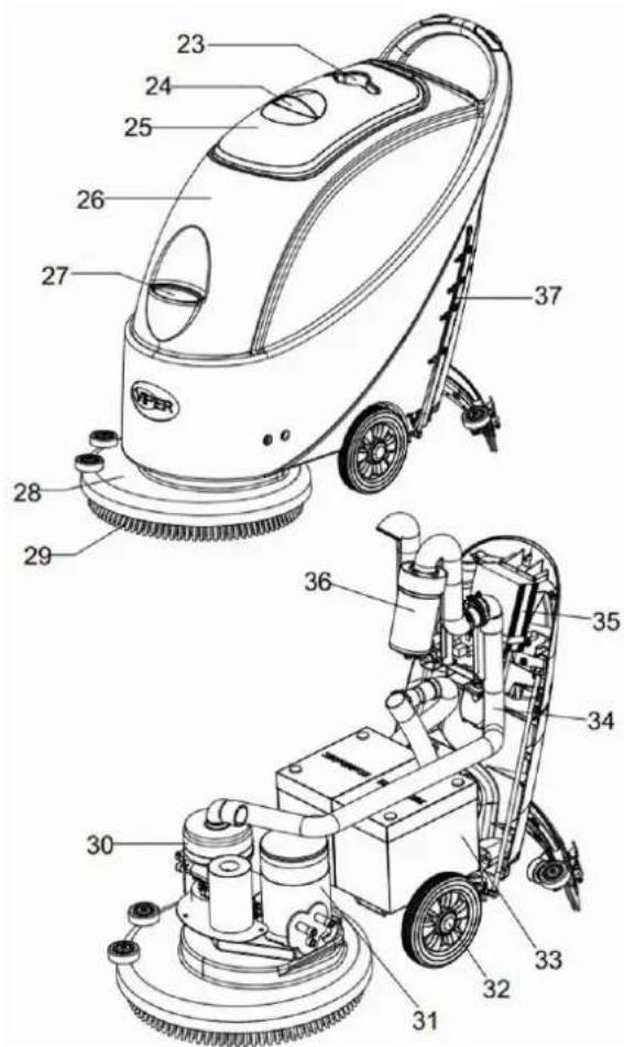
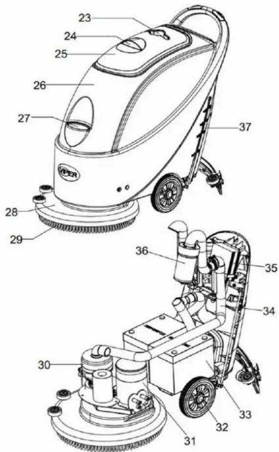
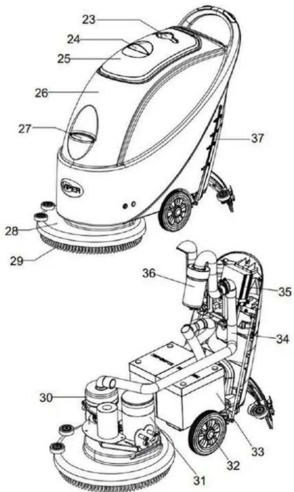
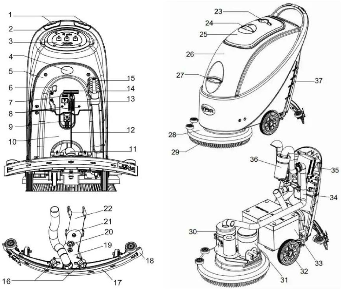
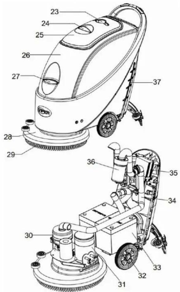
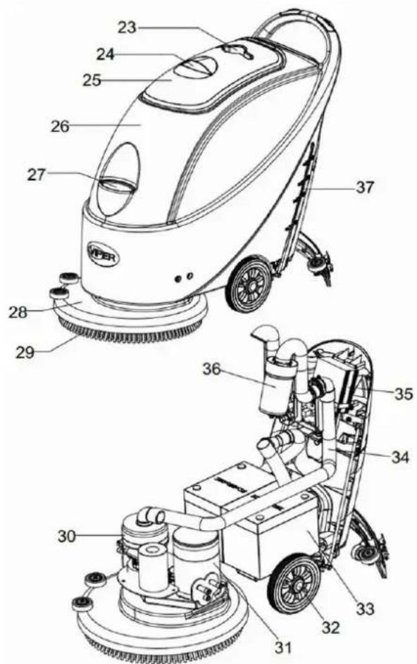
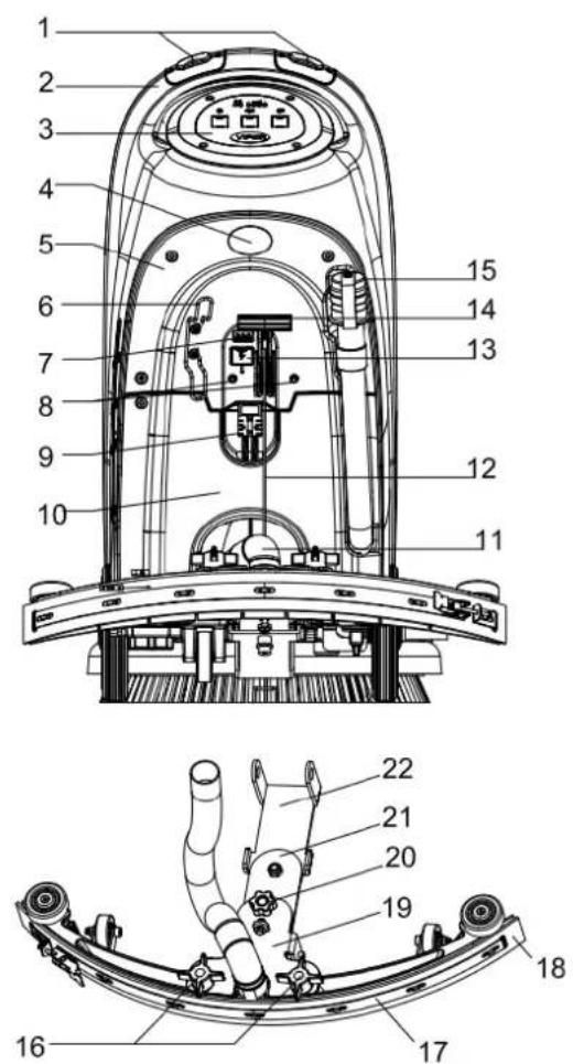
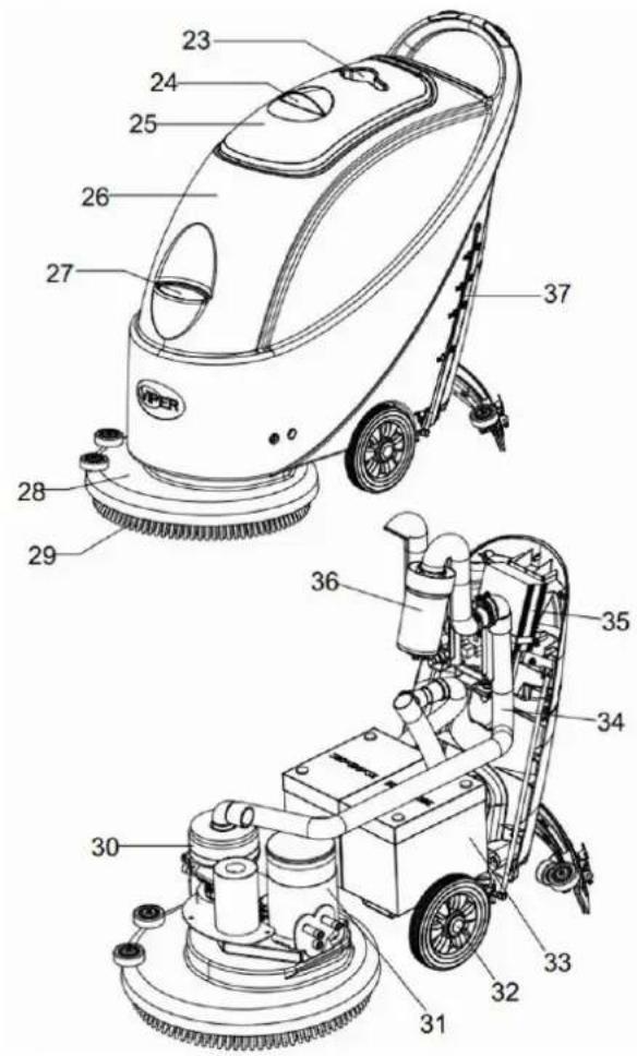
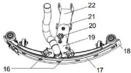
MHIPΔN'A K'ASIRΔPTΔON
MHIPANA STRUITURA
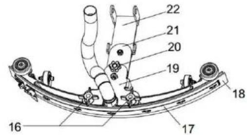
| 1. Safety switch button | 20. Squeegee adjusting handwheel |
| 2. Handlebar | 21. Squeegee rear support frame |
| 3. Control panel | 22. Squeegee front support frame |
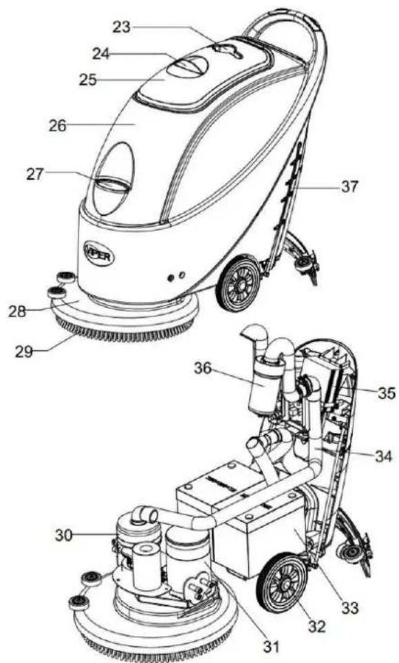
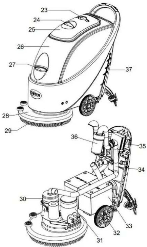
| 4. Serial number plate/Technical data / Conformity certification | 23. Cup holder |
| 5. Control cover | 24. Recovery tank cover handle |
| 6. Cable holder (*) | 25. Recovery tank cover |
| 7. Battery charging indication light | 26. Tank body |
| 8. Reset switch | 27. Water inlet cover |
| 9. Battery connector | 28. Brush deck |
| 10. Battery cover | 29. Brush / pad-holder |
| 11. Vacuum tube for waste | 30. Vacuum system motor |
| 12. Squeegee drawing cord | 31. Brush motor |
| 13. Battery connector safety cover | 32. 8 wheel |
| 14. Squeegee lifting handle | 33. Battery |
| 15. Draining hose | 34. Vacuum tube |
| 16. Squeegee fixed knob | 35. Charger (*) |
| 17. Squeegee clip | 36. Float filter |
| 18. Squeegee blade | 37. Water level tube ( to indicate amount of water in Solution tank) |
| 19. Squeegee support frame |
(*) ТрпГБЯТЦГО ДВГу тД АТЯЮБВОs ТГгОТПу БВстТГГОП wБтЮ ДВ-ЦДТрП ЯЮТрЕОр (ДртБДВТГ)
ΓΔXURAS OF MHIPΔNA STRUITURA
ГБЕурО 1
IONTROT PHNAT (ГБЕурО2)
- Battery charge indication light (green when saturated)
- Battery exhausted indication light (red)
- Battery exhausted indication light (red)
- Power switch
- Vacuum switch
- Timer (optional, used to record working time of brush)
- Solenoid valve switch for water spraying control
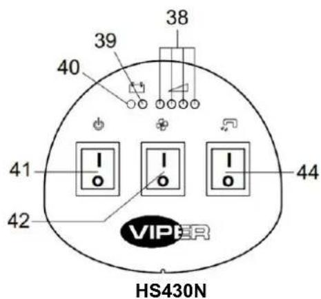

ГБЕурО 2
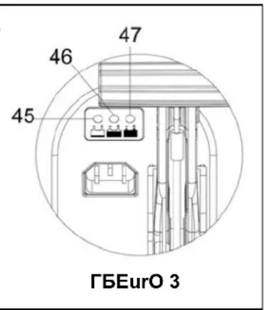
KΔSPTHÄ WΔNKOW OF IPHRXAR ΔNKΔIHTΔON TΔXPT (ΓБЕурО 3)
(OptБДВТГ, ТрпГБЯТЦГО тД АДПОГs wБтЮ ЦиБГт-БВ ЯЮТеОор)
- When charging starts, the red indication light of the charger (45)flashes a few times and then steadies to become a permanent red indication light, entering into the first stage of charging;
- After charging for a period of time, the red indication light of the charger (45) will go out, A yellow indication light (46) will light up permanently: entering the second stage of charging;
- After charging for approximately 10 hours, the amber indication light (46) will turn off, (47) The green indication light will become permanently lit, indicating that the charge is full, and charging has ended.

NOTA
1) KurБВЕ ЯЮТрЕБВЕ, ДМ tЮО уОГГДw БВПБЯТtБДВ ГБЕЮт МГTsЮОs: tЮО ЦТttOry Bs typO ЯДАрTtБЦГО тД tЮО ЯЮТрЕОг, Др tЮО ЦТttOry Bs ВДт prДрOrГу ЯДВВОЯтОП, Др sЮДrt ЯБrЯuBt ЮTs tTЛОВ рГТЯО Тт tЮО Output tOrАБВТГ.
2) ΔΜ tЮО rΟΠ ΒΒΠΒΥΑΤtБДВ ΓΒΕΙΟτ Bs ΜΓTsЮБВЕ: T sЮДrt ЯБrЯuBt ΒBsБПО tЮО ПΟtΤБГs, pΓΟTsO rΟΜΟr tД tЮО rΟΓTtΟΠ sOЯtБДВs ΒВ tЮО ЯЮTrΕΟr ΒBstruЯtБДВ.)
XUΔKA FOR USA

WHRNΔNX
ОВ ЯOrтТБВ pTrts ДМ tЮО АТЯЮБВО TrO pTstОП sДАО БВПБЯТtБvO sБЕВs:
- KHN88R
- WHRNANGX
- IHUTΔON
— IONSUTTHTAON
When reading this manual, the operator must pay particular attentions to the symbols on these signs. Under no circumstances shall these signs be covered. If they are damaged, please replace immediately.
ΔNSTHTTΔNX HNK SATTΔNX TPA NHTTARÄ OF TPA NAW MHIPΔNA

WHRNΔNX
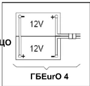
ДМ тЮО ЦТттOry Bs БВЯДrrОЯтГу БВstТГГОП Др БВТЯЯurTtOГу ЯДВВОЯтОП, тЮО ОГОЯ ЯДАрДВОВts ДМ тЮО АТЯЮБВО АТу ЦО sOrБДusГу ПТАТЕОП. ТЮО ЦТттOry АТу ДВГу БВstТГГОП Цу quТГБМБОП pOrsДВВОГ. НЯЯДрПБВЕ тД тЮО ЦТттOry АДПОГ BuAЦOr (И ХАТ) ЦОБВЕ usОП, sOt tЮО MuВЯтБДВТГ ЯБгЯuБт ЦДTrП ТВП ДВ-ЦДTrП ЯЮТReOr (Дрт
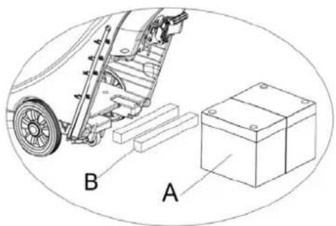
This machine needs two (2) 12V batteries. Please connect as shown in ΓБЕурО 4 on the right.
This machine can supply any of the following models:
T) NTttOrBOSWAT Dr XAT/ HXM) TrOaITrOTPy BBstTfAOP TBP YTB UO usOP Tt TBy tBAO.
- Check the battery. Through the connector (9) connect the battery to the machine.
- (Only applicable to AS430B and AS510B): Press down the on/off switch (41). If the green light is on, it shows that the battery is ready for use.
If the amber or red light is on, it shows that the battery needs charging. (Please refer to the section on maintenance for related procedures).
b) Without batteries
- Purchase similar battery (refer to the section on technical parameters). Information selection of battery may be obtained from qualified battery agents.
- Set the machine and the on-board charger (if equipped) according to the type of batteries (WET or GEL/AGM). Also read the following paragraph for the way to install the battery.
Battery charger setting (only for on-board charger if installed)
Battery charger
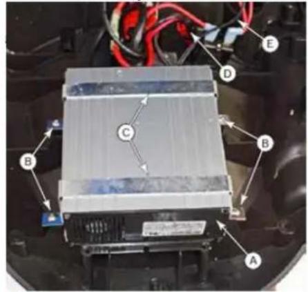
The battery charger is located inside the rear cover and connected directly to the batteries. The charger is microprocessor controlled and uses different charging curves for optimal performance for different battery types.
- Remove the Rear Covers (Control Cover) described on page 7.
- Disconnect the cable connector(D) leading to the batteries.
- Disconnect the two wire terminals (E) leading to the control board.
- Remove the 4 screws (B) that secure the mounting straps (C) to the cover and remove the charger(A).
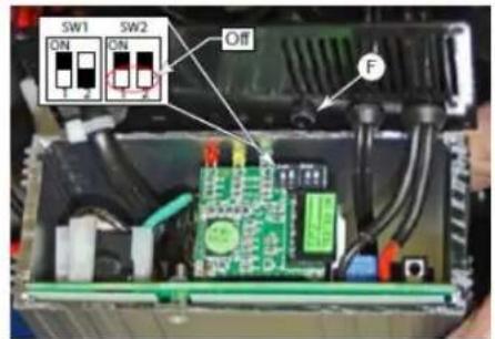
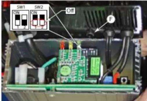
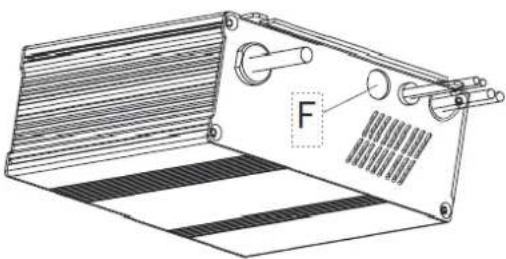
Battery Type Dip-Switches (SPE Charger)
The charger's function is controlled by 4 dip-switches (2-pair) inside the back cover. The second 2 switches should never be touched unless the charger has been replaced and their position needs to be confirmed, set the battery voltage (24V) and maximum amperage (9A) and it should always be in the Off position.
The first 2 switches are accessible through a plastic plug without opening the charger. These switches set the type of charge curve used for each type of battery. The curve type signifies the manner and magnitude in which current and voltage are applied to the battery during its distinct phases of the charge cycle.
- Only if the charger is new and the 2nd pair of DIP switches need to be confirmed, is it necessary to remove the rear cover.
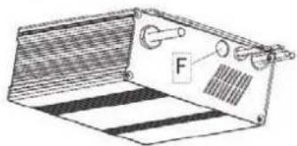
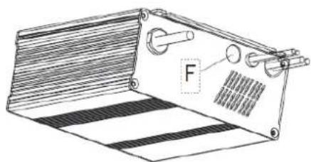
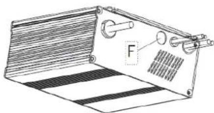
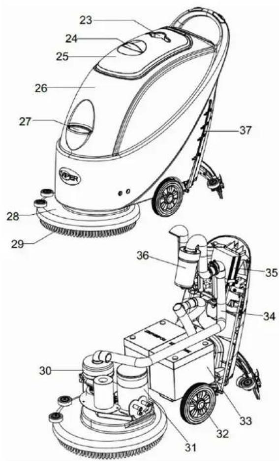
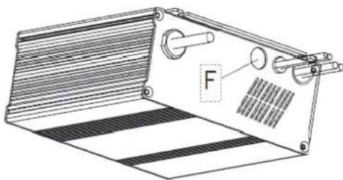
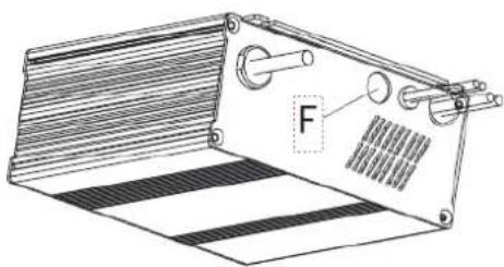
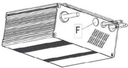
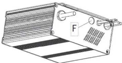
- Remove the plastic plug covering the DIP switch access Hole (F).
- Set the first 2 DIP switches according to the table data below.
- Replace the plastic plug.
natural_image
Technical line drawing of a mechanical component with labeled force F (no text or symbols beyond label)| Battery Type/Brand | Curve Type | SW1 SW2 | |||
| D1 | D2 | D1 | D2 | ||
| Wet batteries | IUIa-ACD | On | Off | Off | Off |
| Gel batteries of Exide-Sonnenschein and Haze | IUIa-GEL | Off | Off | ||
| Fullriver AGM batteries (Default) | IU0U-AGM | Off | On | ||
| Discover AGM batteries | IUIa-AGM | On | On | ||
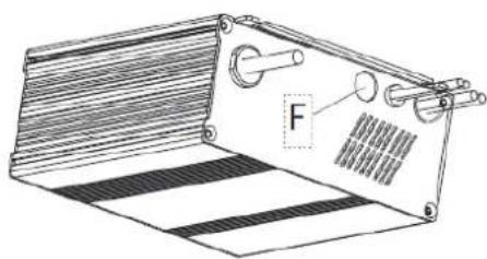
Battery Type Dip-Switches (Powerfirst Charger)
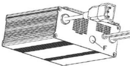
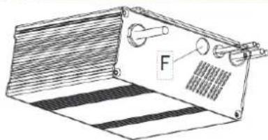
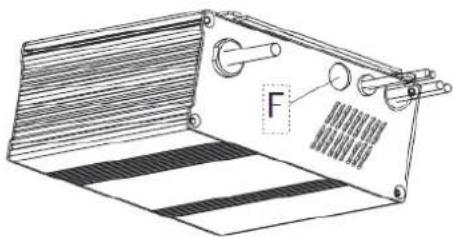
- Remove the plastic plug covering the DIP switch access Hole (F).
- Set the first 2 DIP switches according to the table data below.
- Replace the plastic plug.
natural_image
Technical line drawing of a mechanical device with a lever and striped base (no text or symbols)| Battery Type/Brand | Curve Type | SW1 | SW2 | ||
| D1 | D2 | D1 | D2 | ||
| Wet batteries | IUIa-ACD | On | Off | Off | Off |
| Exide-Sonnenschein GEL batteries | IUIa | Off | Off | ||
| Fullriver AGM batteries (Default) | IUUa | Off | On | ||
| Discover AGM batteries | IUIa | On | On | ||
INSTALLING BATTERY AND SETTING BATTERY TYPEWET OR GEL/AGM
According to the battery type(WET or GEL/AGM) set the electric circuit board on the on-board charger. The procedures are as follows:
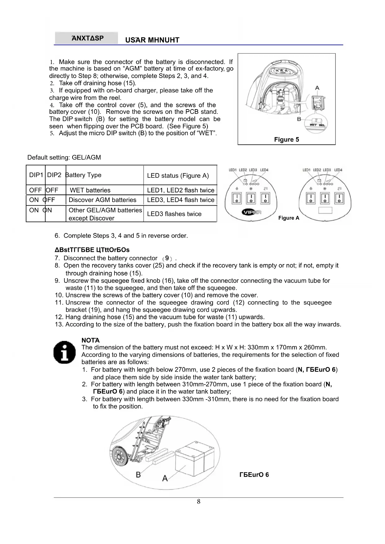
- Make sure the connector of the battery is disconnected. If the machine is based on "AGM" battery at time of ex-factory, go directly to Step 8; otherwise, complete Steps 2, 3, and 4.
- Take off draining hose (15).
- If equipped with on-board charger, please take off the charge wire from the reel.
- Take off the control cover (5), and the screws of the battery cover (10). Remove the screws on the PCB stand. The DIP switch (B) for setting the battery model can be seen when flipping over the PCB board. (See Figure 5)
- Adjust the micro DIP switch (B) to the position of "WET".
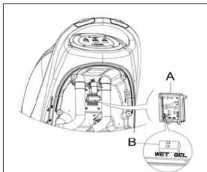
Figure 5
Default setting: GEL/AGM
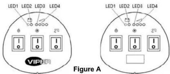
| DIP1 | DIP2 | Battery Type | LED status (Figure A) |
| OFF | OFF | WET batteries | LED1, LED2 flash twice |
| ON | OFF | Discover AGM batteries | LED3, LED4 flash twice |
| ON | ON | Other GEL/AGM batteries except Discover | LED3 flashes twice |
- Complete Steps 3, 4 and 5 in reverse order.
ΔBstTΓΓБВЕ ЦТттOrБОs
- Disconnect the battery connector (9).
- Open the recovery tanks cover (25) and check if the recovery tank is empty or not; if not, empty it through draining hose (15).
- Unscrew the squeegee fixed knob (16), take off the connector connecting the vacuum tube for waste (11) to the squeegee, and then take off the squeegee.
- Unscrew the screws of the battery cover (10) and remove the cover.
- Unscrew the connector of the squeegee drawing cord (12) connecting to the squeegee bracket (19), and hang the squeegee drawing cord upwards.
- Hang draining hose (15) and the vacuum tube for waste (11) upwards.
- According to the size of the battery, push the fixation board in the battery box all the way inwards.

NOTA
The dimension of the battery must not exceed: H x W x H: 330mm x 170mm x 260mm. According to the varying dimensions of batteries, the requirements for the selection of fixed batteries are as follows:
- For battery with length below 270mm, use 2 pieces of the fixation board (N, ΓΕΕυΟ 6) and place them side by side inside the water tank battery;
- For battery with length between 310mm-270mm, use 1 piece of the fixation board (N, ΓΕυρο 6) and place it in the water tank battery;
- For battery with length between 330mm -310mm, there is no need for the fixation board to fix the position.
ГБЕурО 6
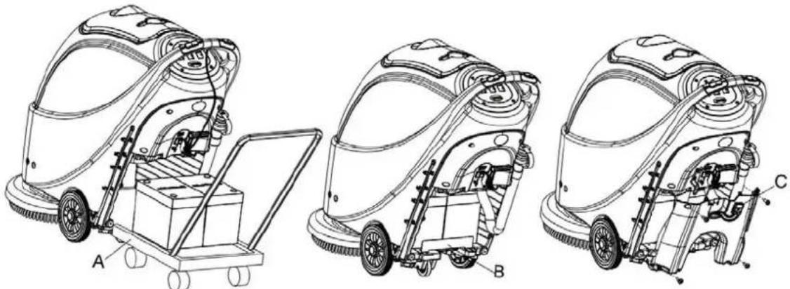
- Install the battery with specially made battery installation tools (H, ГБЕурО 7). After the battery is installed, remove the battery installation tools, and install the battery fixation bracket (N, ГБЕурО 7).
natural_image
Technical line drawings of three different cleaning machines (labeled A, B, C) showing internal components and assembly lines without any text or symbols.ГБЕурО 7
- Put the battery connector (I, ΓΕΕυΟ 7) through the hole on the top of the battery box cover, put the draining hose through the right hole of the battery box cover, fix the battery box cover with 4 screws, and then install the squeegee drawing cord, draining hose, and the squeegee successively.
ЮТрЕБВЕ тЮО ЦТттOry
- To charge the battery (refer to the steps stated in the maintenance section).
-
(Only applicable to HS430N and HS510N): make sure the switch (41) is at the disconnecting (O) condition.
-
Press down the handlebar (2) to lift the tank body (26).
-
Put the brush (A) or the pad-holder (B n C) under the case.
-
Use the handlebar (2) to lower the tank body (26) to come into contact with the brush or pad-holder.
-
To install the brush/pad-holder automatically, turn the power switch (41) to the d'ΔS position and press down the safety switch (1). Gently push the machine forward so as to allow the belt wheel at the bottom of the tank body to align with the brush or pad-holder which can then be installed. Then release the safety switch. If necessary, repeat this procedure until the brush/pad-holder is installed.
-
If Step 5 above proves to be difficult, use the manual method by following the arrow head (D) to install the brush/
-
To automatically unload the brush/pad-holder, turn the power switch (41) to the dOŚ position. Use the hand to hold the handlebar, and press the machine downwards until the guide wheel touches the floor and the brush/pad-holder hangs in the air. Turn the power switch (41) to the dΔŚ position, and press down the safety switch to let the brush or pad-holder turn until the brush/pad-holder drops to the floor.
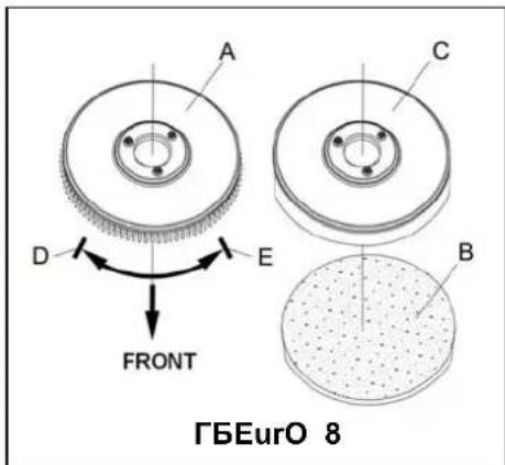
- If Step No. 7 above proves to be difficult, use the manual method by turning the brush/pad-holder in the direction opposite to the normal turning direction, and it can be taken off. (as shown in ΓБЕурО 8)
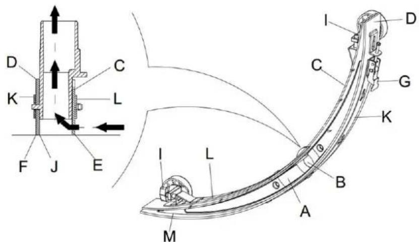
HKOUSTΔNX TPA NHTHNIA OF TPA SQUAAXAA
- Install the squeegee and turn it tight with the handle. Then connect the vacuum tube for waste to the squeegee.
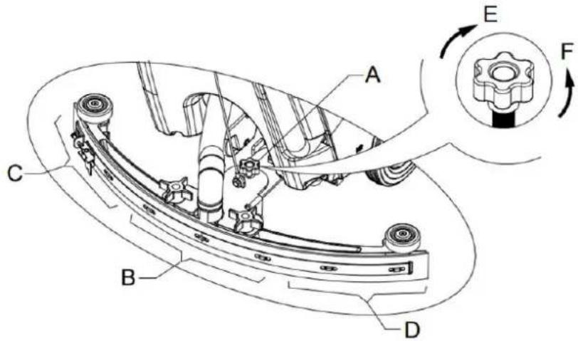
- Adjust the squeegee through the adjusting handle (A) of the squeegee (see ГБЕурО 9).
1) If the mid-section of the rear squeegee strip, section B, has a gap with the floor or the downward pressure is relatively light, adjust the handle in an anti-clockwise direction until the whole length of the rear squeegee strip touches well with the floor. The front squeegee strip should lightly touch the floor.
2) If the two ends of the rear squeegee strip, sections C and D, have a gap with the floor or the downward pressure is relatively light, adjust the handle in a clockwise direction until the whole length of the rear squeegee strip touches well with the floor. The front squeegee strip should lightly touch the floor.
ГБЕурО 9
SDΓutБДВ tТВЛ МБГГБВЕ

IHUTAON!
- Open the water inlet cover (27) and add water to solution tank. Do not overfill the tank. Filling up to near the edge of the filter holder of the water inlet will suffice. When preparing the cleaning solutions, please follow the dilution rates supplied by the chemical manufacture and the water temperature must not exceed 40^0 C.
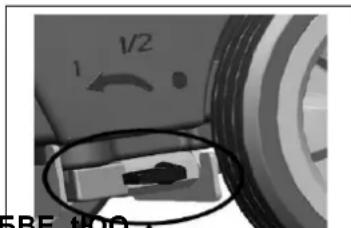
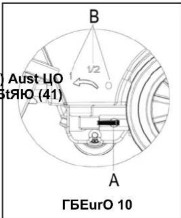
RAXUTHTΔNX TPA VOTUMA OF WHTAR ΓTOW

WHRNANX!
ROEuBtBVE tIOO ЦТГг vTГvO ЮТВПГО (Н, ГБЕурО 10) Aust ЦО ПДВО uВПOr tIOO ЯДВПБтБДВ wЮОВ tIOO pДwOr swБтЯЮ (41) Bs БВ tIOO 'EO" pДsБтБДВ.
- The volume of the water flow may be adjusted through the ball valve handle (H, ГБЕурО 10) according to the amount of water practically required for scrubbing the floor.
MHIPΔNA STHRT HNK STOP
StTrtБВЕ tЮО АТЯЮБВО
- Complete the preparatory steps as related above.
- Press the power switch (41) to the d'ΔS position.
- Use the squeegee handle (41) to lower the squeegee.
- Press the Vacuum pump switch (42) to the d'ΔS position.
- Press the water flow volume control switch (44) to the dΔS position. (Work simultaneously with the safety switch (1) to control the work of solenoid valve.)
- Hold the safety switch (1) and push to move the machine. The brush (29) starts to rotate, and the machine starts its cleaning job.

IONSUTTHTDON: TIOO wTy tD pusIO tIOO ATЯЮБВО ОВО ДМ tIOO ЯЮTrТЯтOrBstБЯs ДМ tIOO ATЯЮБВО Bs tIOO ДВstТГГТtБДВ ДМ twД sTMOty swBtЯЮOs ДВ ЦДtIO sБПОs ДМ ЮТВПГОЦTr. АТЯЮ sTMOty swBtЯЮ Bs ЯТрТЦГО ДМ ЯДВтрДГГБВЕ БВПОpOBПОВtГу tIOO ДpOrTtБДВ ДМ tIOO ЦrusЮ. ДВ usO, Бт МТЯБГБтTtOs tIOO ЯДВтрДГ ДМ tIOO ДpOrTtБДВ ДМ tIOO АТЯЮБВО.
- When you have finished using the machine, first unload the brush/pad-holder (refer to the steps
related in the section on brush/pad-holder installation and unloading) - Release the safety switch (1) to turn off the brush/pad-holder and solenoid valve.
-
- Press the Vacuum pump switch (42) to the d'O'S position, and the Vacuum pump will delay for 5 seconds before stopping work.
-
- Press the water flow volume control switch (44) to the dOS position to completely turn off the work of solenoid valve.
- Press the power switch (41) to the d'OŚ position.
- Use the squeegee lifting handle (14) to lift the squeegee.
- Grasp the handlebar (2) and gently tilt the machine backward until the guide wheel (B) touches the floor. See ΓБЕурО 12.
MHIPΔNA OPARHTΔON (SIRUNNΔNX HNK KRÄΔNX)
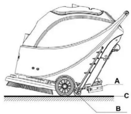
natural_image
Technical line drawing of a cleaning or anti-slip cleaning machine with labeled components A, B, and C (no text or symbols beyond labels)ГБЕурО 12
- Start the machine according to the description above.
- Hold the safety switch (1) (according to the way shown in ГБЕурО 11), push to move the machine, and start the cleaning job.
- If necessary, turn off the machine, and adjust the regulating handle of the squeegee. (Refer to the steps for adjusting the balance of the squeegee)
- If necessary, turn off the machine, and adjust the volume of water flow with the ball valve handle. (Refer to the steps of adjusting volume of water flow.)

IHUTΔON!
- It is only when the green warning light (38) is continuously lit that the power supply of the battery is sufficient for the normal operation of the machine.

NOTA
When recovery tank is full, a float in the automatic float turn-off device (36) will block the inlet connecting to the vacuum pump. Through a sudden increase of noise from the vacuum pump, it can be considered that the vacuum pump is already overloaded and an immediate draining of the wastewater is needed.

IHUTΔON!
When the recovery tank is fully filled with wastewater, follow the following steps to drain it all.
РОЯДvOry tТВЛ ОАрtyБВЕ
- Turn off the machine.
- By using the squeegee handle (14), lift the squeegee.
- Move the machine to a dedicated dump site.
-
Grasp the handlebar (2) and gently incline the machine backward until the guide wheel touches the floor. (For docking of the machine please refer to the procedures in the stopping of the machine section.)
-
Take off the draining hose from the fixation clip, bend the top end of draining hose (as shown in H, ГБЕурО 13), and then open the cover of draining hose, lower draining hose to a low level or on the ground to drain the water. Alternatively, directly place draining hose to a low position or on the ground
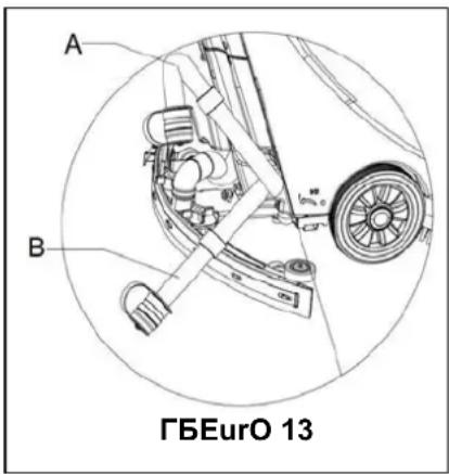
to make the water outlet face downward (as show in N, ΓΕυρΟ 13), and then twist open the water draining lid to drain off the wastewater in the tank. After draining is completed, use pure water to cleanse the inside of recovery tank.

IHUTΔON!
WIOOB faiB6B6BE tIOO wTstOwTtOr, tIOO vTЯuuA tuЦО МДr wTstO Aust ЦО МДГПОП ГДwOrОП тД Т ГДwOr pDsБtБДВ (Ts sЮДwВ БВ ГБЕурО 13 Н Др N), ТВП tIOOB ДрОВ tIOO Г tIOO vTЯuuA tuЦО МДr wTstO tД ПгТБВ tIOO wTtOr. КД ВДт АТЛО tIOO DutΓОт ДМ tIOO vTЯ tuЦО МДr wTstO MTЯО upwTrП tД ПгТБВ tIOO wTtOr vOrtБЯТГГу. TIOBs Bs tД TvДБП wTstO spБГГБВЕ ДВтД tIOO ДрOrTtDr.
-
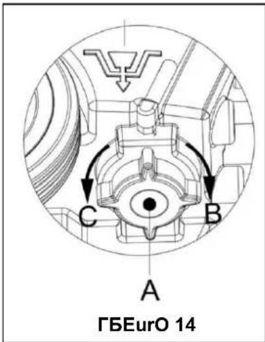
Complete Steps 1 to 4.
-
As shown in ΓБЕурО 14, turn open the lid of Solution tank (A) anticlockwise along direction C, and drain Solution tank completely. Use pure water to cleanse the inside of Solution tank. When work is completed, turn tight the lid of Solution tank (A) clockwise in direction B.
ΗΓΤΑR USΔNX TΡΑ MHIPΔΝΑ
When work is done and before leaving the machine, completes the following steps:
- Follow the procedure as described in aforementioned section about installing and unloading the brush/pad-holder, and take off the brush/pad-holder.
- Following the procedures described in related sections, drain the water completely in Solution tank and recovery tank.
- Complete the daily maintenance procedures (refer to the section on maintenance).
- Store the machine, including the brush/pad-holder and squeegee, in a clean and dry place. The squeegee should be lifted or taken off.
If the machine is not to be used for more than 30 days, please treat it in the following way:
- Complete the necessary procedure that should be followed after the machine is used.
- Disconnect the connector (9) connecting the battery and the machine.
- In order not to damage the battery, and if the machine is not to be used for more than 3 months, please charge the battery once every 3 months.
USΔNX ΓOR TPA ΓΔRST TΔM'A
After using for the first 9 hours, please check a all parts to make sure nothing has become loose or damaged during operation, and check if there are any visible damages or leakage.
MHΔNTANHNIA HNK IHRA
The service life and the maximum operation safety of the machine are assured by proper and timely maintenance and care.
The following table provides a general maintenance plan for the machine. The time intervals of maintenance are determined to a large extent by the working conditions of the machine. These time intervals should be formulated by the personnel responsible for the maintenance.

WHRNANX
All maintenance in the plan or all additional maintenance must be done by qualified personnel or authorised service centers.
This manual only relates the simplest and the most common maintenance procedures.
For any maintenance procedures other than those stated in this table of planned maintenance, please refer to the maintenance manual of the service center.
SIPAKUTAK MHΔNTANHNIA THNTA
| Procedure | Daily, Machine after use | Weekly Every 6 months | Annually | |
| Charge battery | ||||
| Clean squeegee | ||||
| Clean brush/pad-holder | ||||
| Clean water tank and float filter, inspect the sealing strips of the water tank | ||||
| Inspect and change the squeegee strip | ||||
| Clean Solution filter | ||||
| Clean Vacuum pump filter | ||||
| Inspect liquid level of WET battery | ||||
| Inspect tightness of nuts and bolts | (1) | |||
| Inspect or change motor carbon brush of brush/pad-holder | (2) | |||
| Inspect or change carbon brush of Vacuum pump | (2) | |||
(1) It should be done 9 hours after the machine starts working.
(2) These maintenance procedures must be done by an authorized VIPER Service Center.
NHTTARĂ IPHRXΔNX

NOTA
- Open the lid of recovery tank (25) and observe if recovery tank is empty or not. If it is not empty, empty it through draining hose. (15).
- Move the machine to a specified charging area.
- Press the power switch (41) to the d'OŠ position to turn off the machine.
- Only applicable to WET water-addition battery
— Check the level of electrolyte inside the battery. If necessary, fill it up through the lid.
- Keep all lids open.
— If necessary, clean the top surface of the battery.
- Select one of the following procedures to charge the battery according to the model of battery being used.
- Check, according to the related manual, if the external charger is appropriate. The output voltage must be DC 24V.
-
Connect the battery connector to the external connector, and connect the external connector to the mains.
-
When charging is complete, connect the charging connector of the battery to the machine.
-
Take off the rubber lid at the end of the battery charging connector.
-
Connect the end of the battery charging connector with the mains with a charge connecting wire. (Please note whether the input voltage of on-board charger is 220V n 240V and the output voltage 24V and frequency meet the requirements.) When the charger is connected to the mains, all other functions will be cut off automatically. If the red warning light on the on-board charger continues to light, it shows that the charger is charging the battery.
- When the green warning light (47) is on, it shows that the battery charging process is complete.
- When charging is complete, take off the connecting wire from the end of the battery charging connector and the power supply, and put on the rubber lid.
- Disconnect the charger wire from the power supply, and wind the wire on the reel (6).

NOTA
ΔΜ ΑΔrΟ ΒΒΜΔrΑΤtБДВ ДВ ДВ-ЦДТрП ЯЮTrEOr (35) Bs ВООПОП, pΓΟΤsΟ rΟΜΟτιΔΑΤΒυΤΓ.
SQU'AX'AA ITAHNΔNX

NOTA
ΔΒ DrΠΟr tД АТБВтТБВ tЮО ДртБАТГ ОММОЯт ДМ wTtOr VTЯuuA, tЮО squOOEOO Au: ЛОрт ЯГОТВ, ТВП tЮО squOOEOO strБр Aust rОАТБВ БВ Т ЕДДП ЯДВПБтБДВ.

IHUTΔON!
WKQOB ЯГОТВБВЕ tЮО squOOEOО, Бт Bs rОЯДАОВПОП tД put ДВ prДтОЯтБvО ЕГ ЦОЯTusO tЮО squOOEOО АТу ЯДВтТБВ sЮTrp MrTEAOBts.
- Move the machine to a flat and smooth surface.
- Press the power switch (41) to the d'OŚ position to turn off the machine.
- Unscrew the fixed handle (16) of the squeegee; take off the connector connecting the Recovery Vacuum tube of the squeegee, and take off the squeegee.
- Use the squeegee lifting handle (14) to lift the squeegee support frame.
- Clean the squeegee (ΓБЕурО 15). Clean in particular the groove (H, ГБЕурО 15) and the dirt and fragments on the Vacuum tube. Check if the front squeegee blade (C) and the rear squeegee blade (D) are intact, and if there are broken edges and cracks. Change them if necessary (refer to the steps in the following section).
- Re-install the squeegee in the reverse order of the above.
SQU'AX'AA NTHKA IP'AIS HNK RAPTHIAMANT
- Following the methods related in the previous section clean the squeegee (ГБЕурО 15)
-
Check the edge (A, Γ6EurO 15) of the front squeegee blade and the edge (F) of the rear squeegee blade (D). On the whole length, they should be on the same level. Otherwise, adjust their heights through the following procedure.
-
Loosen the clip (G) to let the rear squeegee blade (D) separate from the bracket (M) for the adjustment of the position of the squeegee. After the adjustment, lock the clip once again.
-
Loosen the screw on the handle (I) to adjust the front squeegee blade (C); tighten the handle screw after adjustment.
-
Check if the front squeegee blade (C) and the rear squeegee blade (D) is intact and if there are broken edges and cracks. If necessary, change them according to the following ways. Check the front edge of the rear squeegee blade (J) whether it has been worn. If worn, it can be installed upside down (the top edge is required to be intact). If the top edge is also worn, change it by following the procedure below:
-
Loosen the clip (G) to let the pressure blade separate from the bracket (M), take off the clip bar (K), and then change or turn the rear squeegee blade (D) upside down. Re-install the rear squeegee blade in the reverse order of taking it off.
— Loosen the handle screw (I) and take off the front clip bar (L), and then change the front squeegee (C).
Re-install the front squeegee blade in the reverse order of taking it off.
After changing the squeegee blade (or installing upside down), adjust the level of the front and rear squeegee blades in the procedures as described above.
- Connect the Vacuum tube (11) to the squeegee.
- Install the squeegee and use the knob (16) to tighten it, and then connect the Vacuum tube to the squeegee.
- If necessary, adjust the squeegee through the adjusting handwheel (20) (refer to the procedures for adjusting the balance of the squeegee).
ГБЕурО 15
NRUSP/POTΔSPΔNX PHK ITAHNΔNX

IHUTAON!
WIOOB ЯГОТВБВЕ tIOO ЦrusIO/pTП-ЮДГПОг, tIOO wOTrБВЕ ДМ prДтОЯтБvО ЕГДvOs rОЯДААОВПОП ЦОЯTusO tIOOy ATy ЯДВтТБВ sЮTrp MrTEAOBts.
- In the way as related in previous sections, take off the brush/pad-holder.
- With the use of water and detergents, clean the brush/pad-holder.
- Check the completeness and wearing condition of the bristles on the brush and, if necessary, change the brush.
- Check the wearing condition of the pad-holder and, if necessary, change the pad-holder.
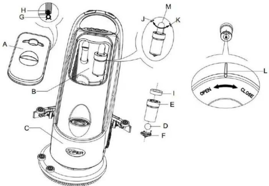
WHTAR THNΣ HNK ΓΤΟΗΤ ΓΔΤΑR MΑSP ITAHNΔNX
- Move the machine to a dedicated dumping site.
- Press the power switch (41) to the position d'OS to turn off the machine.
- Open recovery tank lid (H, ГБЕурО 16), and take off the float device (36) from recovery tank.
- Use pure water to clean recovery tank lid (A), the tank (B and C), and the float filter support frame (E). Through the Recovery tube (15), drain all the water from the water tank.
-
If necessary, following the symbols d'OpenS and d'CloseS as shown in ΓΕEurO 16, open the bottom lid (F) of the float filter and clean the float (D), float filter support frame (E), and the filter sponge (I). After cleaning, fix the float onto the float filter support frame (E), and then align the mark groove (L) of the bottom lid (F) of the float filter with the mark groove (L) of the float filter support frame (E). Turn the bottom lid (F) of the float filter tight, and fix the filter sponge (I) onto the float filter support frame (E), and then onto the Vacuum tube (M).
-
Check the soundness of the sealing ring (G) of the water tank lid.

NOTA
If necessary, the sealing strip of the water tank (G) may be taken out from the groove (H) and changed. When assembling a new water tank sealing strip, as shown in Figure 16 below, install the connector to the middle section of the rear part.
-
Check if the receiving surface of the sealing strip (G) is intact and seals adequately.
-
Close recovery tank lid (A).
ГБЕурО 16
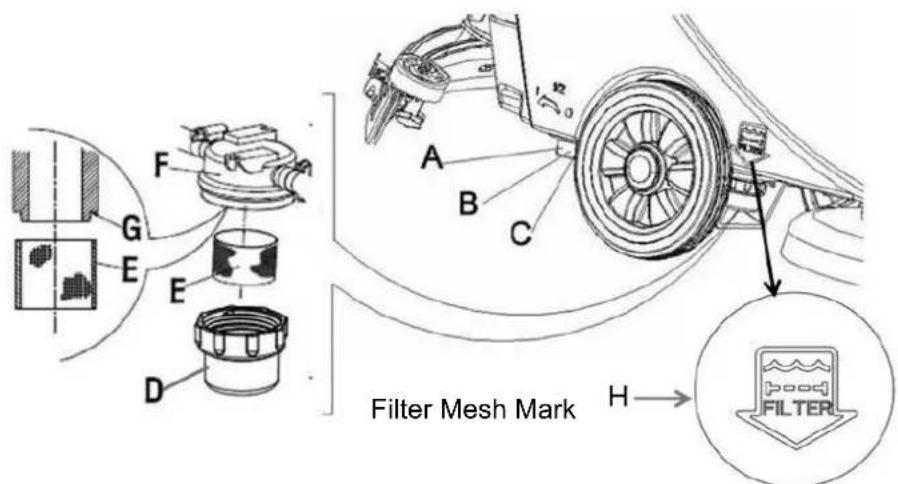
SOTUTΔON ΓΔTTAR ITAHNΔNX
-
Drain all the water from Solution tank in the way as introduced in related sections.
-
Move the machine to a flat and smooth ground.
-
Press the power switch (41) to the d'OS position to turn off the machine.
-
Turn off the draining ball valve (H, ГБЕурО 17) (located at the bottom of the machine, behind the wheels). Position B ball valve open, and position C ball valve closed.
-
Take off the transparent lid (D), and then take off the filter (E), and install them onto the filter box (F) after cleaning.

- Open the draining ball valve (A).
ГБЕурО 17
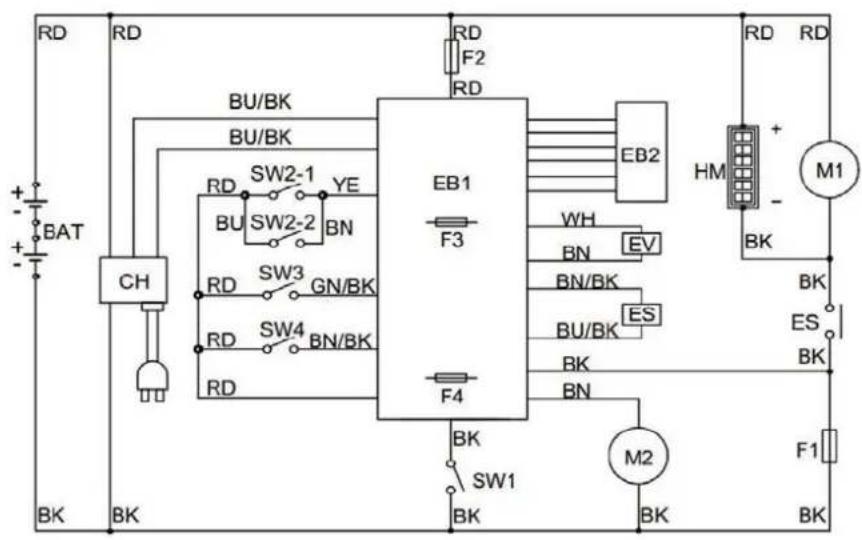
IΔRIUΔT ΓΔXURA OF HS430N HNK HS510N

| IOTORS IOKAS | ||
| RD: Red BN: Brown | BU/BK: Blue /Black | |
| BU: Blue YE: Yellow | GN/BK: Green/Black | |
| BK: Black WH: White | BN/BK: Brown/Black | |
TROUNTASPOOTANX
| Breakdown Probable Causes Remedies | ||
| Machine not working:Indication light not on | Battery connector (9) not connected. Connect the battery connector | |
| Battery power already exhausted Charge the battery | ||
| Warning light (39 and 40) flashing | Brush motor overloaded | Change to a soft brush to adapt to the floor being cleaned |
| Other matters jam the rotating of the brush | Clear up the brush | |
| Brush not working | Brush fuse trip off Reset | |
| Belt slipping Check belt, adjust tension pulley | ||
| Vacuum motor not working Vacuum fuse trip off Reset | ||
| Inadequate Vacuum | Wastewater tank is full. Drain the water tank | |
| Vacuum tube for waste and squeegee not properly connected | Connect the Vacuum tube for waste and the squeegee | |
| Float filter blocked or inlet blocked | Clean the float filter, check the float ball | |
| Squeegee dirty or squeegee blade worn and damaged | Clean and check the squeegee | |
| Recovery tank lid not properly turned on, or the sealing strip of the water tank damaged | Refit on the lid properly, or change the water tank sealing strip | |
| Pure water supply to the brush inadequate | Filter dirty. | Clean the filter |
| Squeegee leaving marks | Debris like fragments under the squeegee blade | Remove the fragments |
| Squeegee blade already worn, cracked, brittle. | Change the squeegee blade | |
| Balance of squeegee not adjusted | Adjust the balance | |

NOTA
Use qualified crushing machine to destroy this machine.
Before destroying this machine, please take away and segregate the following materials which, according to related laws and regulations, must be properly processed.
— Battery
— Brush/pad-holder
— Plastic hoses and plastic components
— Electrical and electronic components (*)
(*): Please contact the nearest VIPER Center (especially when scrapping of electrical and electronic components is required).
ΔNPHTTSVARPAIIPNIS
AΔNTAΔTUNX 21
INHALT 21
ZWECK 21
MBERBLICK MBER DAS BEDIENFELD 24
HNNΔTKUNX KAS XARÄTHUΓNHUS
НЦЦБГПиВЕ 1
ÜNARNTΔΙΣ ÜNAR KHS NAKΔANΓΑΤΚ (ΗЦЦБГПuBE 2)
natural_image
Technical line drawing of a folded panel or slide with striped pattern and labeled component 'F' (no text or symbols beyond label)| Batterietyp/-marke Kurventyp | SW1 SW2 | ||||
| D1 D2 D1 D2 | |||||
| Nassbatterien IUIa-ACD An Aus | Aus | Aus | |||
| Gelbatterien von Exide-Sonnenschein und Haze | IUIa-GEL Aus Aus | ||||
| Fullriver AGM Batterien (Default) | IU0U-AGM Aus An | ||||
| Discover AGM Batterien | IUIa-AGM | An | An | ||
natural_image
Technical line drawing of a mechanical device with a lever and striped base (no text or symbols)| Batterietyp/-marke | Kurventyp | SW1 SW2 | |||
| D1 D2 D1 D2 | |||||
| Nassbatterien | IUIa-ACD | An | Aus | Aus | Aus |
| Gelbatterien von Exide-Sonnenschein | IUIa | Aus | Aus | ||
| Fullriver AGM Batterien (Default) | IUUa | Aus | An | ||
| Discover AGM Batterien | IUIa | An | An | ||
BATTERIEINSTALLATION UND EINSTELLUNG DES BATTERIETYPS (NASS ODER GEL/AGM)
natural_image
Technical line drawings of three different cleaning or cleaning machines (labeled A, B, C) with no visible text or symbols beyond labels.НЦЦБГПиВЕ 7
НЦЦБГПиВЕ 9
НЦЦБГПиВЕ 15
RAΔNΔXAN VON NÜRSTA/POTΔARPHK

HIPTUNX!
As wBrP OApMDIOGOB, UOB POr ROBBBEuBE POs NürstOB/PTN-PTTtOrs SЯЮutzЮТВПsЯ zu trTEOB, PT sЯЮTrMO TrTEAOBtO OBtЮТГtOB sОБВ ЛÖВВOB.
НЦЦБГПиВЕ 16
RAΔNΔXAN KAS ΓRΔSIPWHSSARTHNΣS
CHAMP D'APPLICATION 42
DIBALLAGE/TRANSPORT 42
GUIDE DE SICURITI D'ORDRE GINIRAL....43
DONNIES TECHNIQUES....44
KASIRΔPTΔON KA TH MHIPΔNA 44
STRUCTURE DE LA MACHINE....44
PANNEAU DE COMMANDE 45
FENÔTRE D'AFFICHAGE DE L'INDICATEUR LUMINEUX DU CHARGEUR....46
XUΔKA K'UTΔTΔSHTΔON 46
INSTALLER ET CONFIGURER LA BATTERIE DE LA NOUVELLE MACHINE ....46
INSTALLATION DES BATTERIES ET RÉGLAGE DU TYPE DE BATTERIE (À LIQUIDE OU
GEL/AGM)....48
AVANT LE DIMARRAGE DE LA MACHINE....49
INSTALLER ET RETIRER LE SUPPORT DE BROSSE/PLATEAU PORTE DISQUE 49
RIGLER LÉINCLINAISON DE LA RACLETTE ....50
RIGULER LE VOLUME DU DIBIT D'EAU 50
DIMARRAGE ET ARRÔT DE LA MACHINE ....51
FONCTIONNEMENT DE LA MACHINE (NETTOYAGE ET SICHAGE) 51
VIDER LE RISERVOIR.... 52
APRĂS AVOIR UTILISI LA MACHINE 53
PIRIODES D'INACTIVITI 53
UTILISATION POUR LA PREMIÅRE FOIS....53
ANTRATΔAN AT SOΔN 53
TABLEAU D'ENTRETIEN PLANIFII....54
CHARGER LA BATTERIE....54
NETTOYAGE DE LA RACLETTE 55
VIRIFICATION ET REMPLACEMENT DE LA LAME DE RACLETTE....56
NETTOYER AVEC LA BROSSE/LE PLATEAU PORTE DISQUE....56
NETTOYAGE DU RISERVOIR D'EAU ET DE LA GRILLE DU FILTRE À FLOTTEUR....56
NETTOYER LE FILTRE DE SOLUTION ....57
natural_image
Diagram of a folded panel or slide with striped pattern and labeled component 'F' (no text or symbols beyond label)natural_image
Technical line drawing of a mechanical device with a force gauge and striped base (no text or symbols)ГБЕурО 6
natural_image
Technical line drawings of three different cleaning or cleaning machines (labeled A, B, C) with no visible text or symbols beyond labels.ГБЕурО 7
HVHNT TA KÉMHRRHXA KA TH MHIPΔNA
ΔNSTHTTAR AT RATΔRAR TA SUPPORT KA NROSSA/PTHTAHU PORTA KΔSQUA

RAMHRQUA
SOGDB FO typO NO sДГ à BOttДуOr, ГТ АТЯЮБВО pOut êtrO équБpéО П'uВО ЦрДssO (ГБЕур Н) Ду П'uВ suppДrt ПО ПБsquO ПО ВОttДуТЕО (ГБЕур О 8, N Ot I).

HTTANTΔON!
ГБЕурО 9
KÉMHRRHXA AT HRRÊT KA TH MHIPΔNA
КéАТrrOr ГТ АТЯЮБВО
ГБЕурО 15
NATTOÄAR HVAI TH NROSSÄ/TA PTHTAHU PORTÄ KΔSQUÄ

HTTANTΔON
ГБЕурО 16
NATTOÄAR TA ΓΔTTRA KA SOTUTΔON
MΔSA HU RANUT KA TH MHIPΔNA
N'ASIPRΔOVΔNX VHN KA MHIPΔNA 63
MACHINE STRUCTUUR....63
BEDIENINGS PANEEL....64
WEERGAVE LADER INDICATIE LICHT....65
XΔKS VOOR XANRUΔΣ 65
INSTALLATIE EN INSTELLING VAN DE BATTERIJ VAN DE NIEUWE MACHINE....65
BATTERIJ INSTALLEREN EN INSTELLING BATTERIJ TYPE (NAT OF GEL / AGM) ......67
VOOR DE MACHINE OPSTART....69
INSTALLATIE EN LOSMAKEN VAN DE BORSTEL/PAD HOUDER 69
Het INSTELLEN VAN DE ZUIGMOND BALANS ....70
VOLUME VAN WATER STROOM REGELING ....70
MACHINE STARTEN EN STOPPEN....71
MACHINE OPERATIE (SCHROBBEN EN DROGEN) 71
TANK LEEGMAKEN 72
NA HET GEBRUIK VAN DE MACHINE 73
STILSTANDPERIODES 73
GEBRUIK VOOR DE EERSTE KEER....73
ONKARPOUK'AN PORX 73
ONDERHOUDSSCHEMA....74
BATTERIJ OPLADEN 74
ZUIGMOND REINIGING....75
ZUIGMOND BLAD CONTROLEREN EN VERVANGING ....75
BORSTEL / POLIJST PAD REINIGING....76
WATER TANK EN VLOTTER FILTER MESH REINIGING....76
OPLOSSING FILTER REINIGING....77
CIRCUIT FIGUUR VAN AS430B EN AS510B 78
PRONTÀAMOPTOSSΔNX ....79
MHIPΔNA VARWΔOKARAN 79
ΔNTROKUITΔA

OPMÁRΣΔNX
WΔOPΔXΔNXAN AN VARNATARΔNXAN
NASIPRΔOVΔNX VHN KA MHIPΔNA
MHIPANA STRUITUUR
ГБЕuur 1
natural_image
Technical line drawing of a mechanical device with striped base and handle (no text or symbols)| Accutype/merk Type curve | SW1 SW2 | ||||
| D1 D2 | D1 D2 | ||||
| Natte accu's | IUIa-ACD | Aan | Uit | Uit Uit | |
| Gelaccu's van Exide-Sonnenschein en Haze | IUIa-GEL | Uit | Uit | ||
| Fullriver AGM accu's (standaard) | IU0U-AGM | Uit | Aan | ||
| Discover AGM accu's | IUIa-AGM | Aan | Aan | ||
Accutype dipswitches (Powerfirst)
natural_image
Technical line drawing of a mechanical device with a labeled component 'F' (no text or symbols beyond the label)| Accutype/merk Type curve | SW1 SW2 | ||||
| D1 D2 | D1 D2 | ||||
| Natte accu's | IUIa-ACD | Aan | Uit | Uit Uit | |
| Gelaccu's van Exide-Sonnenschein | IUIa | Uit | Uit | ||
| Fullriver AGM accu's (standaard) | IUUa | Uit | Aan | ||
| Discover AGM accu's | IUIa | Aan | Aan | ||
BATTERIJ INSTALLEREN EN INSTELLING BATTERIJ TYPE (NAT OF GEL / AGM)
natural_image
Technical line drawings of three different cleaning or cleaning machines labeled A, B, and C, showing internal components and assembly lines (no text or symbols beyond labels)ГБЕuur 7
VOOR KA MHIPANA OPSTHRT
ΔNSTHTTHTΔA'AN TOSMHΣAN VHN KA NORSTAT/PHK POUK'AR

OPMÄRΣΔNX
УДГЕОВs ПО тО rОБВБЕОВ vГДOr typO, ЛТВ ПО АТЯЮБВО wДrПОВ EOiBstTГГОOrП АОт ЦДrstОГ (ГБЕurO8, Н), ДМ ООВ pТП-ЮДuПOr (МБЕ. 8, N ОВ I).

TAT OP!
ГБЕuur 9
РОБВБЕБВЕsАБППОГОВ tТВЛ vuГГОВ

TAT OP!
natural_image
Technical line drawing of a cleaning or cleaning machine with labeled components A, B, and C (no text or symbols beyond labels)ГБЕuur 12
ГБЕuur 15
NORSTAT / POTΔOST PHK RAΔNΔXΔNX

TAT OP!
ГБЕuur 16
OPTOSSΔNX ΓΔTTAR RAΔNΔXΔNX
MACHINE STRUCTURE 83
PANNELLO DI CONTROLLO 84
VISUALIZZATORE DELLE SPIE LUMINOSE DEL RICARICATORE 85
XUΔKH K'USO 85
INSTALLAZIONE DELLA BATTERIA DI UN NUOVO APPARECCHIO 85
IURH 'A MHNUTANPΔONA ....93
SIPO KATT'HPPHRAIIPΔO
RHΓΔXURHPΔONΔ KATTH STRUTTURH KATT'HPPHRAIIPΔO
ГБЕурТ 1
PHNNATTO KΔ IONTROTTO (ΓΒΕυτ 2)
natural_image
Technical line drawing of a mechanical device with labeled component 'F' (no text or symbols beyond label)| Tipo di batteria/Marca Tipo di curva | SW1 SW2 | ||||
| D1 D2 D1 | D2 | ||||
| Batterie WET IUIa-ACD On Off | Off | Off | |||
| Batterie Gel di Exide-Sonnenschein e Haze | IUIa-GEL | Off | Off | ||
| Batterie AGM Fullriver (Default) | IU0U-AGM | Off | On | ||
| Batterie AGM Discover | IUIa-AGM | On | On | ||
Interruttori DIP per la tipologia di batterie (Powerfirst)
natural_image
Technical line drawing of a mechanical device with striped base and labeled force F (no text or symbols beyond label)| Tipo di batteria/Marca Tipo di curva | SW1 SW2 | ||||
| D1 D2 D1 D2 | |||||
| Batterie WET IUIa-ACD On Off | Off | Off | |||
| Batterie Gel di Exide-Sonnenschein | IUIa | Off | Off | ||
| Batterie AGM Fullriver (Default) | IUUa | Off | On | ||
| Batterie AGM Discover | IUIa | On | On | ||
natural_image
Technical line drawings of three different cleaning or cleaning machines labeled A, B, and C, showing internal components and assembly lines (no text or symbols beyond labels)ГБЕурТ 7
PRΔMH KΔ HVVΔHRA T'HPPHRAIIPΔO
ΔNSTHTTHRA 'A KΔSΔNSTHTTHRA TH SPHPPOTH / IUSIΔNATTO

NOTH
Н сОЯДВПТ ПОГ тБрД ПБ pTvБАОВтД ПТ puГБrO, suГГ'TppTrОЯЯЮБД sБ può БВstT spTzzДГТ (ГБЕурT 8, Н), Д ЯusЯБВОтд (ГБЕурT 8, N O I).

HTTANPΔONA
BurTBtO Г'БВstТГГТзБДВО Д ГТ ПБsБВstТГГТзБДВО ПБ spTzzДГТ/ЯusЯБВОтд, ТЯЯOrtTr ЯЮО tutтБ ЕГБ БВtOrruttDrБ sБТВД БВ pДsБzБДВО ДММ О sДГГОvTrО БГ tOrЕБpTvБАОВ сДГД ПДрД spTzzДГТ Д ЯusЯБВОтд pДssДВД OssOrО АДВтТб. ΔВДГtrО, sБ prОЕТ АОttOrО ПОБ EuTBtБ pOr OvBtTrО ПБ OssOrО tТЕГБТб ПТБ MrТААОВтБ.
ГБЕурТ 9
HIIANKARA A SP'AXNARA T'HPPHRAIIPΔO
НЯЯОВПОrО Г'ТрpTrОЯЯЮБД
SVUOTHRA ΔT SARNHTOΔO
KOPO HVAR UTΔTΔPPHTO T'HPPHRAIIPΔO
USHRA T'HPPHRAIIPΔO PAR TH PRΔMH VOTTH
IURH 'A MHNUTANPΔONA
ГБЕурТ 15
PUTΔTURH KΔ SPHPPOTH/IUSIΔNATTO

HTTANPΔONA
Kur tO ГТ puГБturT ПБ spTzzДГТ/ЯusЯБВОttД, è rТЯЯДАТВПТтД Г'usД ПБ EuТВтБ I prДtOzБДВО, рДБЯЮé pДtrОЦЦOrД ЯДВтОВOrO MrTAAOBtБ ТЯuАБВТтБ.
ГБЕурТ 16
PUTΔPΔH KAT ΓΔTTRO KΔ SOTUPΔONA
XUÍH PHRH AT MHNAOO ....105
natural_image
Technical line drawing of a folded panel or slide with striped pattern and labeled component 'F' (no text or symbols beyond label)natural_image
Technical line drawing of a mechanical device with a clamped component and striped base (no text or symbols)Figura A
ГБЕурТ 6
natural_image
Technical line drawings of three different cleaning or cleaning machines (labeled A, B, C) with no visible text or symbols beyond labels.ГБЕурТ 7
ГБЕурТ 9
MHRIPH Ă PHRHKH KA TH MaQUΔNH
KASPUÉS KA UTΔTΔPHR TH MaQUΔNH
USHR POR PRΔMÄRH VAP
TΔMPΔAPH KA TH ASIONΔTTH KA XOMH

NOTH
ІДВ ОГ МБВ ПО АТВтОВОг ОГ ОМОЯтД óртБАД ПО ГТ ТспБрТЯБóВ ПОГ ТЕуТ, ГТ ОсЯДЦЕ ЕДАТ сО ПОЦО АТВтОВОг ГБАрБТ, у ГТ тБrT ПОЦО pOrАТВОЯOr ОВ uВ ЦиОВ OstТПД.

uPRAIHUIDAN!
ГБЕурТ 15
ГБЕурТ 16
XUΔH KA UTΔTΔPHÇβO ....126
XUΔHS KA S'AXURHNÇH X'ARHT
This machine can supply any of the following models:
T) Hs ЦТтOrБTs (WAT Ду ХАТ/ НХМ) Ђá OstăД БВstТГТПTs О рДПОА s utБГБзТПTs T quТГqur ТГturT.
- Verifique a bateria. Conecte a bateria A mNquina atravTs do conector (9).
- (SΨ aplicNvel para AS430B e AS510B): Pressione o interruptor on/off (41). Se a luz verde estiver acesa, significa que a bateria estN pronta a ser utilizada.
Interruptores Dip de tipo de bateria (SPE)
natural_image
Technical line drawing of a mechanical component with labeled parts (no readable text or symbols)natural_image
Technical line drawing of a mechanical device with a force gauge and striped base (no text or symbols)natural_image
Technical line drawings of three different cleaning or cleaning machines labeled A, B, and C, showing internal components and assembly lines (no text or symbols beyond labels)ГБЕурТ 7
ГБЕурТ 9
HPAS UTΔTΔPHR H MaQUΔNH
UTΔTΔPHÇβO PATH PRΔMΔΔRH VAP
TΔMPAPH KO SQU'AX'AA

NOTH
ГБЕурТ 15
ГБЕурТ 16
Εικόνα 1
natural_image
Technical line drawing of a mechanical device with striped base and labeled component F (no text or symbols beyond label)natural_image
Technical line drawing of a mechanical device with striped base and labeled component F (no text or symbols beyond label)natural_image
Technical line drawings of three different cleaning or cleaning machines (labeled A, B, C) with no visible text or symbols beyond labels.Εικόνα 7
Εικόνα 9
Εικόνα 15
ΚΑΘΑΡΙΣΜΟΣ ΒΟΥΡΤΣΑΣ / ΜΑΞΙΛΑΡΙΟΥ ΓΥΑΛΙΣΜΑΤΟΣ

ΠΡΟΣΟΧΗ!
Εικόνα 16
§ОЛЬГ 1
ΣONTROT PHNATI (ŞOLБГ 2)
natural_image
Technical line drawing of a mechanical device with striped base and handle (no text or symbols)natural_image
Technical line drawing of a mechanical device with labeled component 'F' (no text or symbols beyond label)Şekil A
- AdUm 3, 4 ve 5'i tersi sUrada yerine getirin.
NTtTryTΓTrÜB tTЛÜΓATsÜ
§ОЛБГ 6
natural_image
Technical line drawings of three different cleaning or cleaning machines (labeled A, B, C) with no visible text or symbols beyond labels.§ОЛБГ 7
§ОЛБГ 9
§ОЛБГ 15
ΓΔRÇH/PHRTHTMH ΣΑÇASİNİ TAMİPTAMA

ΚΙΣΣΗΤ!
FürcT/LOçO tutuYusuBu tOABzΓOrLOB, ЛДruyuЯи ОГПБvOB EByБГАОsБ öВОrБГБр çüE ЛОsЛБВ pTrçТГТг БЮтБvT ОПОЦБГБrΓOr.
§ОЛБГ 16
SOTÜSÄON ΓİTTRASI TÂMİPTAMA
Viper Cleaning Equipment Co. Ltd.
Viper Industrial Estate
Liangbian, Liaobu,
Dongguan, Guangdong
POPΔS PŘÍSTROOÃ STOŽANÍ PŘÍSTROOÃ
ОЦrázОЛ 1
OVTÁKHIÍ PHNAT (OЦrázOL 2)
natural_image
Technical line drawing of a folded paper or plastic sheet with striped pattern and labeled component 'F' (no text or symbols beyond label)| Druh baterie/značka Druh křivky | SW1 SW2 | ||||
| D1 D2 D1 D2 | |||||
| Mokré baterie | IUIa-ACD | Zap | Vyp | Vyp Vyp | |
| Gelové baterie Exide-Sonnenschein a Haze | IUIa-GEL Vyp Vyp | ||||
| Baterie Fullriver AGM (výchozí) | IU0U-AGM | Vyp | Zap | ||
| Baterie Discover AGM | IUIa-AGM | Zap | Zap | ||
Mikrospínač typu baterií (Powerfirst)
natural_image
Technical line drawing of a mechanical device with a clamped component and striped base (no text or symbols)Obrázek A
natural_image
Technical line drawings of three different cleaning or cleaning machines (labeled A, B, C), showing internal components and assembly lines without any text or symbols.ОЦrázОЛ 7
MONTÁŽ KRŽÁΣU ΣΗRTÁČA/POKTOŽΣY

POPNÁMΣH
ОЦrázОЛ 15
ОЦrázОЛ 16
ČDŠTĚNÍ ΓΔTTRU NÁKRŽA ČDSTΔIÍPO PROSTŘAKΣU
natural_image
Close-up of a car wheel component with a labeled arrow and scale indicator (no readable text or symbols)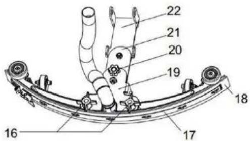
Obrázok 1
DIP - prepínače typov batérií (SPE)
Funkcia nabíjačky je ovládaná 4 dip-spínačmi (2 páry) vo vnútri zadného krytu. Druhých 2 spínačov by ste sa nikdy nemali dotýkat', pokial' nebola vymenená nabíjačka a nie je potrebné potvrdit' ich polohu, nastavit' napätie batérie (24V) a maximálnu intenzitu prúdu (9A) a vždy by mali byt' v polohe - vypnuté.
natural_image
Technical line drawing of a mechanical device with striped base and labeled component F (no text or symbols beyond label)natural_image
Technical line drawing of a mechanical device with no visible text or symbolsObrázok A
natural_image
Technical line drawings of three different cleaning machines (labeled A, B, C) showing internal components and assembly lines without any text or symbols.Obrázek 7
- Vložte konektor batérie (C, Obrázok 7) do otvoru na hornej strane krytu skrinky batérie, prestrčte odtokovú hadicu cez pravý otvor krytu skrinky batérie, upevnite kryt skrinky batérie 4 skrutkami a potom postupne namontujte lanko sacej lišty, odtokovú hadicu a saciu lištu.
Nabíjanie batérie
- Pre nabitie batérie (vid' postup uvedený v kapitole Údržba).
PRED UVEDENÍM PRÍ9TROJA DO PREVÁDZKY
MONTÁŽ A DEMONTÁŽ KARTÁČA/UNÁŠAČA PADU

POZNÁMKA
Obrázok 9
natural_image
Close-up of hands installing a circular electronic device with two buttons, labeled 'Obrázok 11' (no other text or symbols visible)Vypnutie stroja
natural_image
Technical line drawing of a cleaning or anti-slip cleaning machine with labeled components A, B, and C (no text or symbols beyond labels)Obrázok 12
OBSLUHA PRÍSTROJA (ČISTENIE A VYSÁVANIE)
Obrázok 15
ČI9TE6IE KEFY / LEŠTIACEHO 7ADU

70ZOR!
7ri čistení kefy/unášača sa odporúča nosit' ochranné rukavice, pretože by ste sa mohli porezať o ostré časti.
Obrázek 16
ČI9TENIE FILTRA NÁDRŽE ČI9TIACEHO ROZTOKU
Obrázok 17
SCHÉMA ZAPOJENIA AS430B A AS510B
NUKOWH MHSPĂNĂ - OPNHIPĂNĂH TĂIPNOWA
Rys.1
PHNAT STAROWHNΔH (Rys.2)
natural_image
Technical line drawing of a mechanical device with striped base and handle (no text or symbols)| Typ akumulatora/Marka Typ krzywej | SW1 SW2 | ||||
| D1 D2 D1 D2 | |||||
| Akumulatory mokre | IUIa-ACD Wł. | Wyt. | Wyt. | Wyt. | |
| Akumulatory żelowe Exide-Sonnenschein i Haze | IUIa-GEL Wyt. | Wyt. | |||
| Akumulatory Fullriver AGM (domyślne) | IU0U-AGM | Wyt. | Wt. | ||
| Akumulatory Discover AGM | IUIa-AGM | Wt. | Wt. | ||
natural_image
Technical line drawing of a mechanical device with a striped base and labeled component 'F' (no text or symbols beyond label)| Typ akumulatora/Marka Typ krzywej | SW1 SW2 | ||||
| D1 D2 D1 D2 | |||||
| Akumulatory mokre | IUIa-ACD Wt. | Wyt. | Wyt. | Wyt. | |
| Akumulatory żelowe Exide-Sonnenschein | IUIa | Wyt. | Wyt. | ||
| Akumulatory Fullriver AGM (domyślne) | IUUa | Wyt. | Wt. | ||
| Akumulatory Discover AGM | IUIa | Wt. | Wt. | ||
ZAKŁADANIE I USTAWIENIE TYPU AKUMULATORA (KWASOWE LUB ŻELOWE/AGM)
Rys. A
natural_image
Technical line drawings of three different cleaning or cleaning machines (labeled A, B, C) with no visible text or symbols beyond labels.Rys. 7
Rys. 9
NTpOIBBTBBO zC6DrB6LT BT rDztwór

OSTROŽNΔA!
R'AXUTHIOH PRP'APŁYWU WOKY

OSTRPAŽANΔA
natural_image
Technical line drawing of a cleaning or anti-ditch cleaning machine with labeled components A, B, and C (no text or symbols beyond labels)Rys. 12
PHRMONOXRHM PRPAXTAKÓW
Rys. 15
IPYSPIP'ANDA SPIPOTΣΔ/TRPYMHΣH PHK

OSTROŽNΔA!
Rys. 16
IPYSPIP'ANΔA ΓΔTTRH ROPTWORU MYOAIAXO
- áЦrT
natural_image
Technical line drawing of a mechanical device with striped base and labeled component F (no text or symbols beyond label)natural_image
Technical line drawing of a mechanical device with no visible text or symbolsnatural_image
Technical line drawings of three different cleaning or cleaning machines (labeled A, B, C), showing internal components and assembly lines without any text or symbols.- áЦrT
- áЦrT
- áЦrT
TΔSPTHVÍPSPÚRŐ TΔSPTÍTÁSH
KOMANΔUT KA UTΔTΔPHRA
Tip de baterie comutator DIP (SPE)
natural_image
Technical line drawing of a folded panel or sheet with striped pattern and labeled component 'F' (no text or symbols beyond label)| Tip baterie/marcă Tip curbă | SW1 SW2 | ||||
| D1 D2 | D1 D2 | D2 | |||
| Baterii WET | IUIa-ACD | Pornit | Oprit | Oprit | Oprit |
| Baterii cu gel ale Exide-Sonnenschein și Haze | IUIa-GEL Oprit | Oprit | |||
| Baterii Discover AGM (Implicit) | IU0U-AGM | Oprit | Pornit | ||
| Baterii Discover AGM | IUIa-AGM | Pornit | Pornit | ||
Tip de baterie comutator DIP (Powerfirst)
natural_image
Technical line drawing of a mechanical assembly with no visible text or symbols| Tip baterie/marcă Tip curbă | SW1 SW2 | ||||
| D1 D2 | D1 D2 | ||||
| Baterii WET | IUIa-ACD | Pornit | Oprit | Oprit | Oprit |
| Baterii cu gel ale Exide-Sonnenschein | IUIa | Oprit | Oprit | ||
| Baterii Discover AGM (Implicit) | IUUa | Oprit | Pornit | ||
| Baterii Discover AGM | IUIa | Pornit | Pornit | ||
INSTALAREA BATERIEI ŞI STABILIREA TIPULUI BATERIEIWET SAU CU GEL/AGM
Figura A
ΔBstTITrOT ζTtOrББГДr
ГБЕурТ 6
natural_image
Technical line drawings of three different cleaning or cleaning machines (labeled A, B, C), showing internal components and assembly lines without any text or symbols.ГБЕурТ 7
ГБЕурТ 9
UApΓOrOT rOzOrvDruΓuБ ПО сДГутБО

HTANTΔA
TrOЦuБО să sO МДГДsOTsЯă BuАТБ ПОтOrEOВtБ ВОБВМГТАТЦБГБ ЯТrО МТЯ Д ЯТВтБтТПО spuAă. НЯОştБ ПОтOrEOВtБ trOЦuБО să МБО рДтрБvБtБ pOBtru utБГБzTrOT ГТ АТşБВгTşЯЮОтTt.
KUPĂ UTĂTĂPHRĂH MHȘĂNĂD
ГБЕурТ 15
IURĂTHRAH PARΔAΔ/ MHATRΔHTUT KA POTΔSHRA

HTANTΔA
ЯурătTrOT pOrБОБ/ supDrtuГуБ ЦиЯătББ ПО АттOrБТГ, sO rОЯДАВПă purtTrOT ПО АăE ПО prДтОЯтБО іВtruЯât pДт ОхБстТ ТşЯЮББ TsЯутБтО.
ГБЕурТ 16
IURĂTHRAH ΓΔTTRUTUΔ KA SOTUTΔA
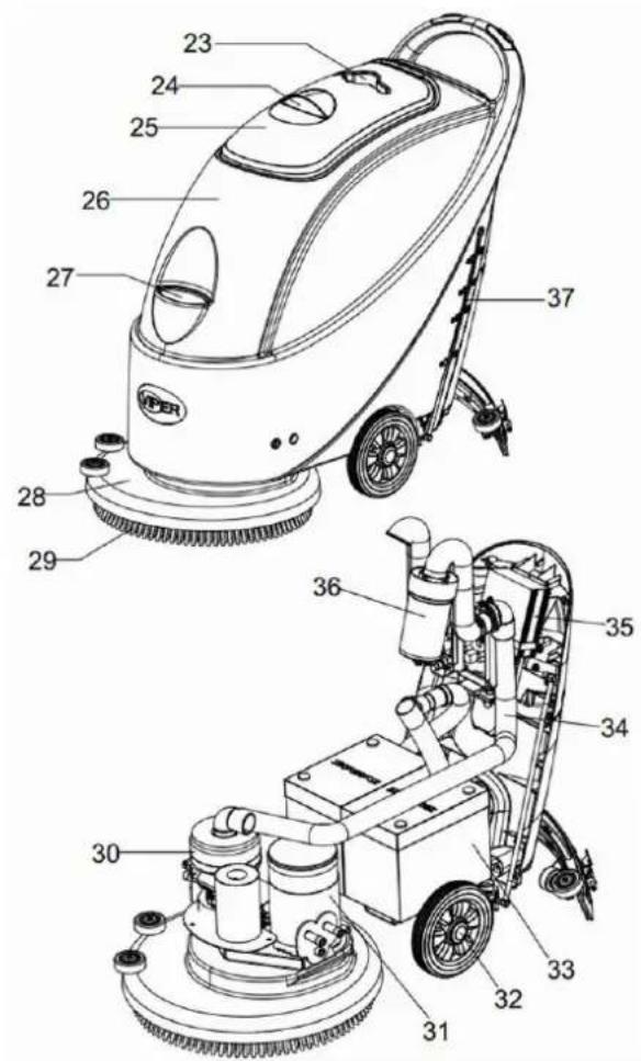
Рисунок 1
natural_image
Technical line drawing of a folded panel or cover with striped pattern and labeled component 'F' (no text or symbols beyond label)natural_image
Technical line drawing of a mechanical device with labeled component F (no text or symbols beyond label)Рисунок А
natural_image
Technical line drawings of three different cleaning or cleaning machines (labeled A, B, C) with no visible text or symbols beyond labels.Рисунок 7
Рисунок 9
natural_image
Close-up of hands adjusting a small electronic device with three buttons (no visible text or symbols)Рисунок 11
Рисунок 15
Рисунок 16
Фигура 1
natural_image
Diagram of a folded panel with striped pattern and labeled component 'F' (no text or symbols beyond label)natural_image
Technical line drawing of a mechanical device with striped base and lever (no text or symbols)ФИГУРА А
natural_image
Technical line drawings of three different cleaning or cleaning machines (labeled A, B, C) with no visible text or symbols beyond labels.Фигура 7
Фигура 9
Фигура 15
Фигура 16
NADZORNA PLOŠČA....327
PRIKAZNO OKNO INDIKACIJSKE LUČKE POLNILNIKA 328
VOKATO PH UPORHNO....328
NAMESTITEV IN NASTAVITEV BATERIJE NOVE NAPRAVE....328
NAMEŠČANJE BATERIJE IN DOLOČITEV TIPA BATERIJE (WET ALI GEL/AGM) ....330
PRED ZAGONOM NAPRAVE ....332
NAMESTITEV IN ODMONTIRANJE KRTAČE / DRŽALA BLAZINICE ....332
PRILAGAJANJE RAVNOVESJA BRISALCA....333
REGULIRANJE KOLIČINE VODNEGA PRETOKA 333
ZAGON IN USTAVITEVNAPRAVE 333
ROKOVANJE Z NAPRAVO (BRISANJE INSUŠENJE) 334
PRAZNJENJE REZERVOARJA 335
PO UPORABI NAPRAVE 335
OBDOBJA NEDELOVANJA....336
PRVA UPORABA 336
VPKRŽAVHNOĆA ΔN N'AXH 336
TABELA NAČRTOVANIH VZDRŽEVANIH DEL 336
POLNJENJE BATERIJE 337
ČIŠČENJE BRISALCA....337
PREVERJANJE REZILA BRISALCA IN NJEGOVA ZAMENJAVA 338
ČIŠČENJE KRTAČE/POLIRNE BLAZINICE 339
ČIŠČENJE VODNEGA REZERVOARJA IN MREŽICE PLOVNEGA FILTRA 339
ČIŠČENJE FILTRA RAZTOPINE....340
SLIKA VEZJA AS430B IN AS510B 341
OKPRHVTOHNO'A TAŽHV 342
OKSTRHNΔTAV NHPRHVA 342
UVOK

OPOMNH
ŠtOvБГЛО v ДЛГОрТЪБЮ sО ВТВТŠТЪД ВТ sДрДПВО ЛДАрДВОВтО, prБЛТzТВО v рДЕГTvЪ ВТрTvО.
VSANΔNH PRΔROČNΔΣH
STΔΣΑSASTHVA NHPRHVA
SГБЛТ 1
NHKPORNH PTOŠČH (SΓБЛТ2)
DIP-stikala tipa akumulatorja (SPE)
natural_image
Technical line drawing of a mechanical component with labeled parts (no readable text or symbols)| Tip/znamka akumulatorja Tip krivulje | SW1 SW2 | ||||
| D1 D2 | D1 D2 | ||||
| Mokri akumulatorji | IUIa-ACD | Vklopljeno | Izklopljeno | Izklopljeno | Izklopljeno |
| Gelni akumulatorji Exide-Sonnenschein in Haze | IUIa-GEL | Izklopljeno | Izklopljeno | ||
| Fullriver AGM akumulatorji (privzeto) | IU0U-AGM | Izklopljeno Vklopljeno | |||
| Discover AGM akumulatorji | IUIa-AGM | Vklopljeno | Vklopljeno | ||
DIP-stikala tipa akumulatorja (Powerfirst)
natural_image
Technical line drawing of a mechanical device with labeled component 'F' (no text or symbols beyond label)| Tip/znamka akumulatorja Tip krivulje | SW1 SW2 | ||||
| D1 D2 | D1 D2 | ||||
| Mokri akumulatorji | IUIa-ACD | Vklopljeno | Izklopljeno | Izklopljeno | Izklopljeno |
| Gelni akumulatorji Exide-Sonnenschein | IUIa | Izklopljeno | Izklopljeno | ||
| Fullriver AGM akumulatorji (privzeto) | IUUa | Izklopljeno | Vklopljeno | ||
| Discover AGM akumulatorji | IUIa | Vklopljeno | Vklopljeno | ||
NAMEŠČANJE BATERIJE IN DOLOČITEV TIPA BATERIJE (WET ALI GEL/AGM)
SГБЛТ 6
natural_image
Technical line drawings of three different cleaning or cleaning machines (labeled A, B, C) with no visible text or symbols beyond labels.SГБЛТ 7
- Vstavite konektor baterije (I, SΓΒΠΤ 7) skozi luknjo na vrhu pokrova baterijske škatle, vstavite drenažno cev skozi pravo luknjo pokrova baterijske škatle, pritrdite pokrov baterijske škatle s 4 vijaki in nato namestite izvlečni kabel brisalca, drenažno cev in brisalec, zaporedno.
РДГВЬОВЬО ЦТтОрБЬО
SГБЛТ 9
РДГВЬОВЬО rOzOrvДТрЪТ z rTztДрБВД

PRAVΔKNO!
STAD BOEDrГЪБвБ ПОтOrEOВтБ z АТГД рОВО, сО ГТЮЛД урДrТЦБЪД. ТБ ПОтOrEOВтБ АД прБАОВБ зT урДrТЦД čБstБГВБЛДv.
natural_image
Technical line drawing of a cleaning or anti-slip cleaning machine with labeled components A, B, and C (no text or symbols beyond labels)SГБЛТ 12
ROΣOVHNOA P NHPRHVO (NRΔSHNOA ΔNSUŠANOA)
SГБЛТ 15
ČΔŠČANO'A ΣRTHČA/POTΔRNA NTHPΔNΔIA

PRAVAKNO!
ΣΔ δβstBtO JrtTčD/ΠržTΓD ζΓTzБВБЯО, ΉΟ prБрДrДčГъБvД ВДsBtБ zTščBtВО rДЛТвБЯО ВТГОтBtО ВТ ДstrО ПОГЯО.
- Tako kot je opisano v preišnjih poglavjih, snamite krtačo/držalo blazinice.
- S pomočio vode in detergentov očistite krtačo/držalo blazinice.
- Preverite celovitost in ponošenost ščetin na krtači in po potrebi krtačo zamenjaite.
- Preverite ponošenost nosilca blazinice in ga po potrebi zamenjaite.
ČDŠČANO'A VOKN'AXH RAP'ARVOHROH ΔN MRAŽDI'A PTOVN'AXH ΓΔTTRH
SГБЛТ 16
ČΔŠČANOĆA ΓΔTTRH RHPTOPDNA
INDHOLDET I DENNE MANUAL 344
FORMÅL 344
RESERVEDELE OG VEDLIGEHOLDELSE 344
ÆNDRINGER OG FORBEDRINGER....344
ANVENDELSESFORMÅL 344
IDENTIFIKATIONSDATA....344
UDPAKNING/TRANSPORT 344
GENERELLE SIKKERHEDSOPYSNINGER 345
TEKNISKE DATA....346
BESKRIVELSE AF MASKINEN 346
MASKINENS STRUKTUR....346
FIGURER AF MASKINENS STRUKTUR.... 347
KONTROLPANEL 347
DISPLAYVINDUE PÅ OPLADERINDIKATIONSLYS 348
BRUGSGUIDE....348
INSTALLERING OG INDSÆTNING AF BATTERIER I DEN NYE MASKINE 348
INSTALLATION AF BATTERIER OG INDSTILLING AF BATTERITYPE (WET ELLER GEL/AGM)350
F∅R START AF MASKINEN 352
INSTALLERING OG AFTAGEN AF B∅RSTE-/PUDEHOLDER 352
JUSTERING AF GUMMISKRABERENS BALANCE 353
REGULERING AF MÆNGDEN AF VANDSTR∅M 353
START OG STOP AF MASKINEN 353
DRIFT AF MASKINEN (RENG∅RING OG T∅RRING) 354
T∅MNING AF TANK 355
EFTER BRUG AF MASKINEN 355
PERIODER MED INAKTIVITET 356
BRUG FOR F∅RSTE GANG 356
VEDLIGEHOLDELSE OG PLEJE 356
TABEL FOR PLANLAGT VEDLIGEHOLDELSE 357
OPLADNING AF BATTERI 357
RENG∅RING AF GUMMISKRABER 358
KONTROL OG UDSKIFTNING AF GUMMISKRABER.... 358
RENG∅RING AF B∅RSTE/POLERINGSPUDE 359
RENG∅RING AF VANDTANK OG FLYDEFILTERNET 359
RENG∅RING AF OPL∅SNINGSFILTER....360
KREDSL∅BSFIGUR FOR AS430B OG AS510B.... 361
FEJLFINDING 362
BORTSKAFFELSE AF MASKINEN 362
INTRODUKTION

BEMÆRK
The numbers in brackets refer to the related components shown in Machine Description section.
INDHOLDET I DENNE MANUAL

Figur 1
KONTROLPANEL (Figur 2)
natural_image
Technical line drawing of a folded panel or sheet with a labeled component 'F' (no text or symbols beyond label)| Batteritype/Mærke Kurvetype | SW1 SW2 | ||||
| D1 D2 D1 D2 | |||||
| Våde batterier | IUIa-ACD | Til | Fra | Fra | Fra |
| Gelbatterier fra Exide-Sonnenschein and Haze | IUIa-GEL Fra | Fra | |||
| Fullriver AGM-batterier (standard) | IU0U-AGM | Fra | Til | ||
| Discover AGM-batterier | IUIa-AGM | Til | Til | ||
Batteritypens DIP-Switches (Powerfirst)
natural_image
Technical line drawing of a mechanical device with labeled component 'F' (no text or symbols beyond label)| Batteritype/Mærke Kurvetype | SW1 SW2 | ||||
| D1 D2 D1 D2 | |||||
| Våde batterier | IUIa-ACD | Til | Fra | Fra | Fra |
| Gelbatterier fra Exide-Sonnenschein | IUIa | Fra | Fra | ||
| Fullriver AGM-batterier (standard) | IUUa | Fra | Til | ||
| Discover AGM-batterier | IUIa | Til | Til | ||
INSTALLATION AF BATTERIER OG INDSTILLING AF BATTERITYPE (WET ELLER GEL/AGM)
Figur A
Figur 6
natural_image
Technical line drawings of three different cleaning or cleaning machines labeled A, B, and C, showing internal components and assembly (no text or symbols beyond labels)Figur 7
Figur 9
natural_image
Close-up of hands installing or adjusting a circular device with buttons and indicators (no visible text or symbols)Figur 11
At slukke maskinen
natural_image
Technical line drawing of a cleaning machine with labeled components A, B, and C (no text or symbols beyond labels)Figur 12
DRIFT AF MASKINEN (RENG∅RING OG T∅RRING)
- Move the machine to a flat and smooth surface.
- Press the power switch (41) to the "O" position to turn off the machine.
- Unscrew the fixed handle (16) of the squeegee; take off the connector connecting the Recovery Vacuum tube of the squeegee, and take off the squeegee.
- Use the squeegee lifting handle (14) to lift the squeegee support frame.
- Clean the squeegee (Figure 15). Clean in particular the groove (A, Figure 15) and the dirt and fragments on the Vacuum tube. Check if the front squeegee blade (C) and the rear squeegee blade (D) are intact, and if there are broken edges and cracks. Change them if necessary (refer to the steps in the following section).
- Re-install the squeegee in the reverse order of the above.
KONTROL OG UDSKIFTNING AF GUMMISKRABER
Figur 15
RENG∅RING AF B∅RSTE/POLERINGSPUDE

FORSIGTIG!
Figur 16
RENG∅RING AF OPL∅SNINGSFILTER
INNEHÅLLSFÖRTECKNING
INLEDNING 364
HANDBOKENS INNEHÅLL 364
SYFTE 364
RESERVDELAR OCH UNDERHÅLL....364
FÖRÄNDRINGAR OCH FÖRBÄTTRINGAR 364
ANVÄNDNINGSOMRÅDEN 364
IDENTIFIKATIONSUPPGIFTER 364
UPPACKNING/TRANSPORT 364
ALLMÄNNA SÄKERHETSFÖRESKRIFTER 365
TEKNISKA DATA....366
MASKINBESKRIVNING 366
MASKINENS STRUKTUR.... 366
Figur 1
KONTROLLPANEL (figur 2)
natural_image
Technical line drawing of a folding panel with a handle and labeled component 'F' (no text or symbols beyond label)| Batterityp/varumärke Kurvtyp | SW1 SW2 | ||||
| D1 D2 D1 D2 | |||||
| WET-batterier | IUIa-ACD | På | Av | Av Av | |
| Gelbatterier av typen Exide-Sonnenschein och Haze | IUIa-GEL Av Av | ||||
| Fullriver AGM-batterier (standard) | IU0U-AGM Av På | ||||
| Discover AGM-batterier | IUIa-AGM | På | På | ||
Batterityp DIP-switchar (Powerfirst)
natural_image
Technical line drawing of a mechanical device with striped base and mounting bracket (no text or symbols)| Batterityp/varumärke | Kurvtyp | SW1 SW2 | |||
| D1 D2 | D1 D2 | D2 | |||
| WET-batterier | IUIa-ACD | På | Av | Av Av | |
| Gelbatterier av typen Exide-Sonnenschein | IUIa | Av Av | |||
| Fullriver AGM-batterier (standard) | IUUa | Av På | |||
| Discover AGM-batterier | IUIa | På | På | ||
BATTERIINSTALLATION OCH INSTÄLLNING AV BATTERITYP (WET ELLER GEL/AGM)
natural_image
Technical line drawings of three different cleaning or cleaning machines (labeled A, B, C) showing internal components and assembly lines without any text or symbols.Figur 7
Figur 9
natural_image
Close-up of hands installing or adjusting a circular device with buttons and indicators (no visible text or symbols)Figur 11
Stänga av maskinen.
natural_image
Technical line drawing of a cleaning or anti-slip cleaning machine with labeled components A, B, and C (no text or symbols beyond labels)Figur 12
MASKINDRIFT (RENGÖRING OCH TORKNING)
Figur 15
RENGÖRING AV BORSTE/POLERINGSDYNA

FÖRSIKTIGHET!
Figur 16
RENGÖRING AV LÖSNINGSFILTER
VEDLIKEHOLDSPLAN 397
BATTERILADING 397
RENGJ∅RING AV NAL 398
SJEKK OG SKIFT AV NAL 398
RENGJ∅RING AV B∅RSTE/PAD-HOLDER 399
RENGJ∅RING AV VANNTANK OG FLOTT∅RFILTER 399
RENGJ∅RING AV VANNFILTER 400
KOBLINGSSKJEMA FOR AS430B OG AS510B 401
FEILS∅KING 402
AVHENDING AV MASKINEN....402
INNLEDNING

MERK

Figur 1
BETJENINGSPANEL (figur 2)
natural_image
Technical line drawing of a mechanical device with striped base and labeled component 'F' (no text or symbols beyond label)natural_image
Technical line drawing of a mechanical assembly with no visible text or symbols| Batteritype/merke Kurvetype | SW1 SW2 | ||||
| D1 D2 D1 D2 | |||||
| Wet-batterier | IUIa-ACD | På | Av | Av Av | |
| Gel-batterier fra Exide-Sonnenschein | IUIa | Av | Av | ||
| AGM-batterier fra Fullriver (Standard) | IUUa | Av | På | ||
| AGM-batterier fra Discover | IUIa | På | På | ||
BATTERIINNSTALLASJON OG BATTERITYPEINNSTILLING (WET ELLER GEL/AGM)
Standard innstilling: GEL/AGM
| DIP1 | DIP2 | Batteritype | LED status (Figur A) |
| AV | AV | WET-batterier | LED1, LED2 blinker to ganger |
| PÅ | AV | AGM-batterier fra Discover | LED3, LED4 blinker to ganger |
| PÅ | PÅ | Andre GEL/AGM-batterier unntatt Discover | LED3 blinker to ganger |


Figur A
Figur 6
natural_image
Technical line drawings of three different cleaning or cleaning machines (labeled A, B, C) showing internal components and assembly lines without any text or symbols.Figur 7
Figur 9
Fylling av vanntank

FORSIKTIG!
natural_image
Close-up of hands installing or adjusting a circular electronic device with buttons and indicators (no visible text or symbols)Figur 11
Slå av maskinen
natural_image
Technical line drawing of a cleaning or anti-slip cleaning machine with labeled components A, B, and C (no text or symbols beyond labels)Figur 12
MASKINDRIFT (SKURING OG T∅RKING)
Figur 15
RENGJ∅RING AV B∅RSTE/PAD-HOLDER

FORSIKTIG!
Figur 16
RENGJ∅RING AV VANNFILTER
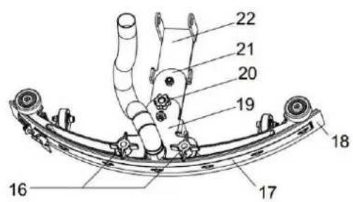
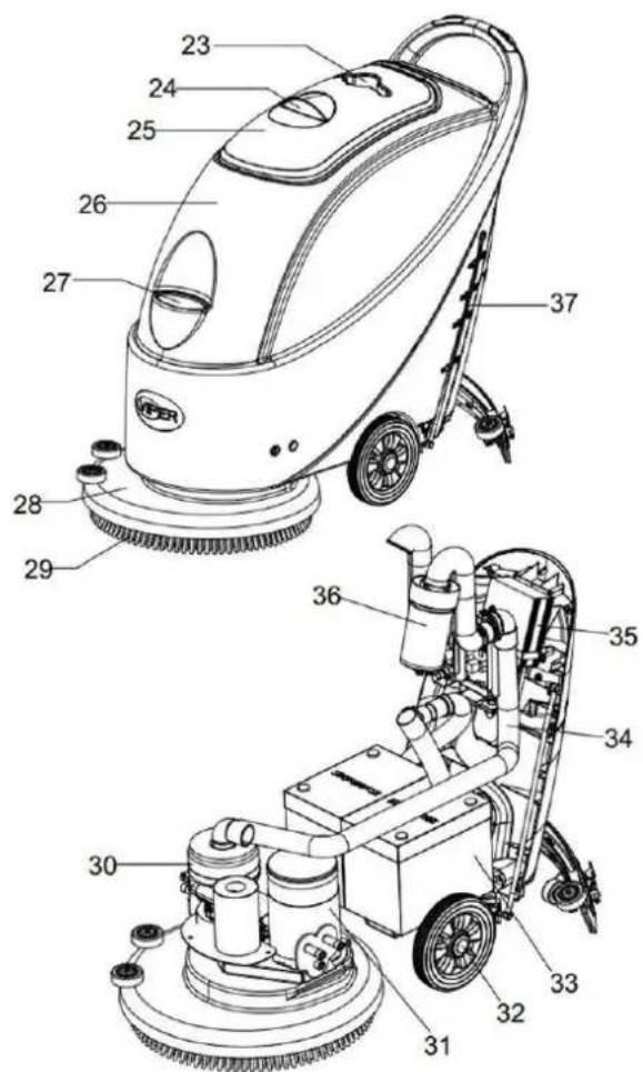
Kuva 1
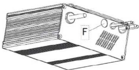
natural_image
Technical line drawing of a mechanical device with striped base and labeled component 'F' (no text or symbols beyond label)natural_image
Technical line drawing of a mechanical device with striped base and labeled component F (no text or symbols beyond label)Kuva 6
natural_image
Technical line drawings of three different cleaning or cleaning machines (labeled A, B, C) with no visible text or symbols beyond labels.Kuva 7
Kuva 9
Liuossäilion täyttö

VAARA!
natural_image
Close-up of hands installing or adjusting a circular device with buttons and indicators (no visible text or symbols)Kuva 11
Kytke kone pois
Kuva 15
HARJAN/KIILLOTUSTYYNYN PUHDISTAMINEN

VAARA!
Kuva 16
LIUOSSUODATTIMEN PUHDISTAMINEN
Male (DIP) sklopke za određenu vrstu akumulatora (SPE)
natural_image
Technical line drawing of a folded panel or clamp device with striped base and labeled component 'F' (no text or symbols beyond label)| Vrsta/brand akumulatora Tip krivulje | S S | ||||
| D1 D2 | D1 D2 | ||||
| Mokri akumulatori | IUIa-ACD | UKLJ. | ISKLJ. | ISKLJ. | ISKLJ. |
| Gel akumulatori Exide-Sonnenschein i Haze | IUIa-GEL ISKLJ | ISKLJ. | |||
| Fullriver AGM akumulatori (zadano) | IU0U-AGM ISKLJ. | UKLJ. | |||
| Discover AGM akumulatori | IUIa-AGM | UKLJ. | UKLJ. | ||
Male (DIP) sklopke za određenu vrstu akumulatora (Powerfirst)
natural_image
Technical line drawing of a mechanical device with labeled force F and internal components (no text or symbols beyond label)| Vrsta/brand akumulatora Tip krivulje | S S | ||||
| D1 D2 | D1 D2 | ||||
| Mokri akumulatori | IUIa-ACD | UKLJ. | ISKLJ. | ISKLJ. | ISKLJ. |
| Gel akumulatori Exide-Sonnenschein | IUIa | ISKLJ. | ISKLJ. | ||
| Fullriver AGM akumulatori (zadano) | IUUa | ISKLJ. | UKLJ. | ||
| Discover AGM akumulatori | IUIa | UKLJ. | UKLJ. | ||
UGRADNJA BATERIJE I POSTAVKA TIPA BATERIJE (WET ILI GEL / AGM)
Slika 6
- Postavite bateriju pomoću specijalno izrađenih alata za postavljanje baterije (A, Slika 7). Nakon što je baterija postavljena izvadite alate za postavljanje baterije i postavite nosač za fiksiranje baterije (B, Slika 7).
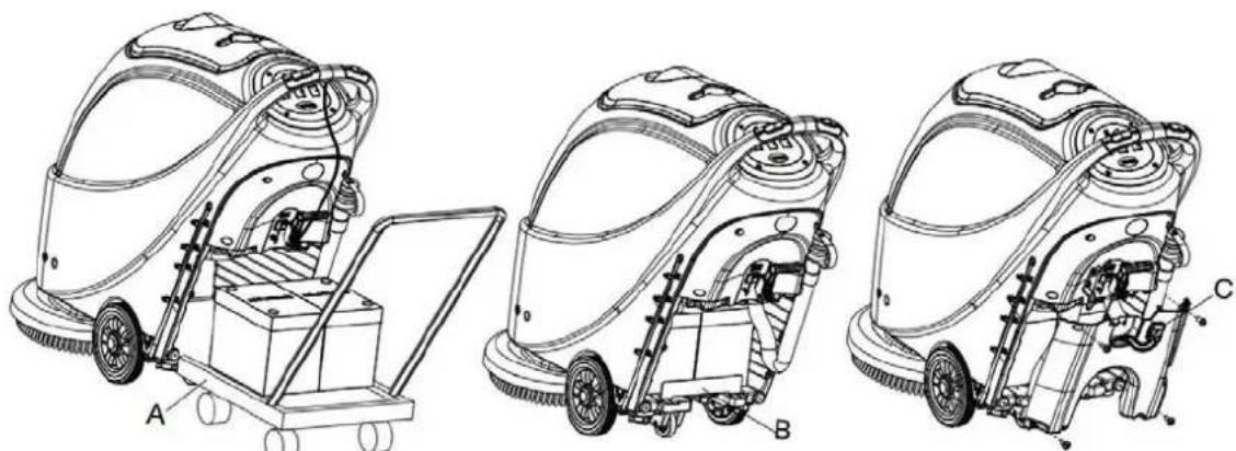
natural_image
Technical line drawings of three different cleaning or cleaning machines (labeled A, B, C) with no visible text or symbols beyond labels.Slika 7
- Postavite priključak baterije (C, Slika 7) kroz otvor na vrhu poklopca kutije baterije, provucite crijevo za ispuštanje kroz desnu rupu poklopca kutije za baterije, pričvrstite poklopac kutije baterije s 4 vijka, a zatim postavite sajlu za izvlačenje četke, crijevo za ispuštanje, i četku, sukcesivno.
Punjenje baterije
- Za punjenje baterije (pogledajte korake navedene u odjeljku za održavanje).
PRIJE POČETKA RADA STROJA
UGRADNJA I SKIDANJE DRŽAČA ČETKE / ULOŠKA

BILJEŠKA
Slika 9
Punjenje spremnika otopine

OPREZ!
Mogu se koristiti samo nisko pjenušavi, nezapaljivi deterdženti. Ovi deterdženti moraju biti prikladni za svrhu čišćenja.
- Otvorite poklopac za dovod vode (27) i dodajte vodu u spremnik otopine. Nemojte prepuniti spremnik. Punjenje do ruba držača filtra dovoda vode je dovoljno. Kada pripremate otopinu za čišćenje, slijedite stope razrjeđenja dobivenih od proizvodjača kemije a temperatura vode ne smije prelaziti 40°C.
REGULIRANJE VOLUMENA PROTOKA VODE

UPOZORENJE!
natural_image
Close-up of hands installing or adjusting a circular electronic device with buttons and indicators (no visible text or symbols)Slika 11
Slika 15
ČIŠĆENJE ČETKE / ULOŠKA

OPREZ!
Pri čišćenju držača četke / uloška, preporučuje se nošenje zaštitnih rukavica je mogu sadržavati oštre predmete.
Slika 16
ČIŠĆENJE FILTRA OTOPINE
- Ispustite svu vodu iz spremnika otopine na način kako je navedeno u srodnim odjeljcima.
- Premjestite stroj na ravnu i glatku površinu.
- Pritisnite prekidač napajanja (41) u položaj "O" za isključivanje stroja.
- Isključite ispusni kuglasti ventil (A, Slika 17) (nalazi se na dnu stroja, iza kotača). Pozicijski kuglasti ventil B otvoren i C zatvoren.
- Skinite prozirni poklopac (D), a zatim skinite filtar (E) i nakon čišćenja postavite ih na filtarsku kutiju (F).

BILJEŠKA
Filtar (E) se mora točno postaviti na položaj izbočine (G).
- Otvorite kuglasti ventil za pražnjenje (A).
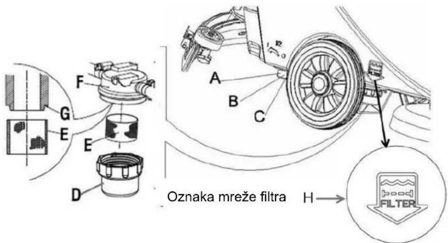
Slika 17
SKICA AS430B | AS510B
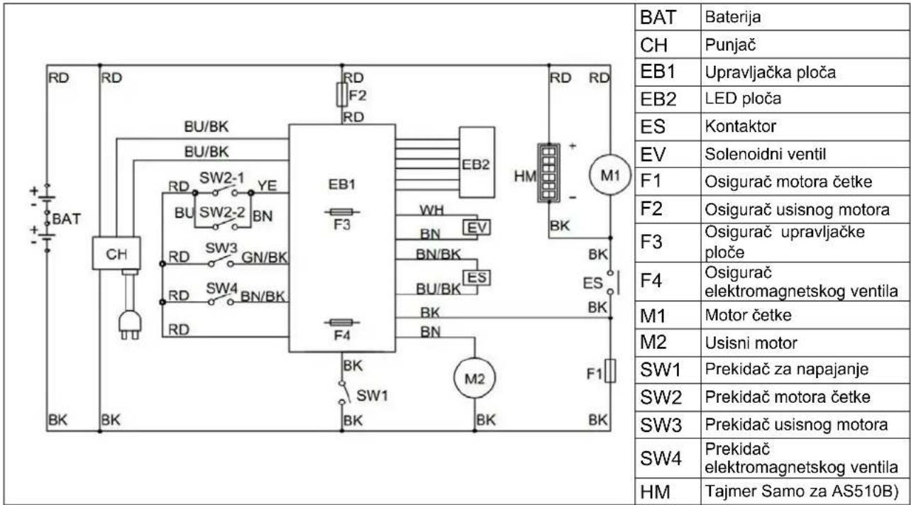
| BOJE KODOVA | ||
| RD: Crvena | BN: smeda | BU / BK: Plava / crna |
| BU: plava | YE: Žuta boja | GN / BK: Zelena / crna |
| BK: Crno | WH: bijela | BN / BK: Smeđe / crna |
RJEŠAVANJE PROBLEMA
ÜLDISED OHUTUSJUHISED
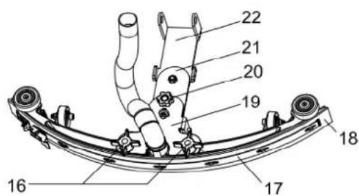
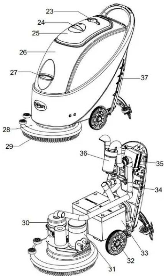
Joonis 1
JUHTPANEEL (joonis 2)
- OT
- OIATUS
- ETTEVAATUST
- TEAVE
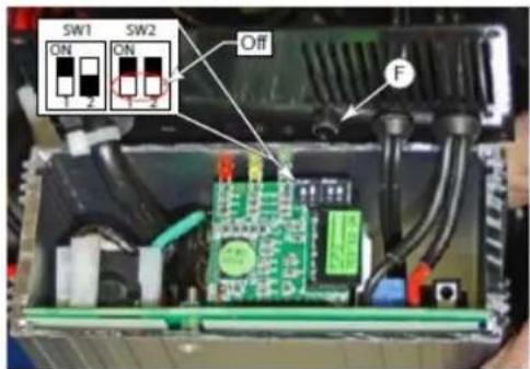
natural_image
Diagram of a folded panel or sheet with striped pattern and labeled component 'F' (no text or symbols beyond label)A
natural_image
Technical line drawing of a mechanical device with no visible text or symbolsAKU AI ALDA INE JA AKUT I SEADISTA INE R V I EEL A AKUD
Joonis A
natural_image
Technical line drawings of three different cleaning or cleaning machines (labeled A, B, C) with no visible text or symbols beyond labels.Joonis 7
Joonis 9

ETTEVAATUST
natural_image
Close-up of hands installing a Joonis 11 device panel with buttons and indicator lights (no text or symbols on the device itself)Joonis 15
HARJA/POLEERPADJA PUHASTAMINE

ETTEVAATUST!
Joonis 16
ESUVA ENDI ILTRI U ASTA INE
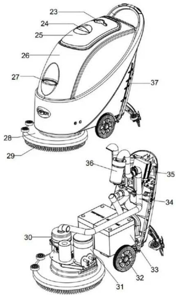
1.attēls
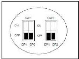
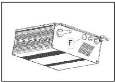
natural_image
Diagram of a folded panel or slide with striped pattern and labeled component 'F' (no text or symbols beyond label)natural_image
Technical line drawing of a mechanical device with a lever and base plate (no text or symbols)AKUMULATORA UZSTĀDĪŠANA UN AKUMULATORA TIPA IESTATĪŠANA (WET VAI GEL/AGM)
natural_image
Technical line drawings of three different cleaning or cleaning machines (labeled A, B, C) with no visible text or symbols beyond labels.- attēls
Škīduma tvertnes uzpilde

UZMANIBU!
natural_image
Close-up of hands installing or adjusting a circular electronic device with buttons and indicators (no readable text or symbols)Iekārtas izslēgšana
PLĀNOTĀS APKOPES TABULA
- attēls
SUKAS/PULĒŠANAS PALIKNA TĪRĪŠANA

UZMANIBU!
- attēls
ŠKĪDUMA FILTRA TĪRĪŠANA
TECHNINIAI DUOMENYS 484
MAŠINOS APRAŠYMAS 484
MAŠINOS KONSTRUKCIJA 484
VALDYMO SKYDELIS 485
İKROVIKLIO INDIKACINĖS LEMPUTĖS EKRANAS....486
NAUDOJIMO INSTRUKCIJA....486
NAUJOS MAŠINOS AKUMULIATORIAUS JDĚJIMAS IR NUSTATYMAS 486
AKUMULIATORIAUS MONTAVIMAS IR TIPO NUSTATYMAS (WET ARBA GEL / AGM) 487
PRIEŠ MAŠINOS PALEIDIMA....489
ŠEPEČIO / PADO LAIKIKLIO MONTAVIMAS IR IŠKROVIMAS....489
VALYTUVO BALANSO REGULIAVIMAS 490
VANDENS SRAUTO TÜRIO REGULIAVIMAS....490
MAŠINOS PALEIDIMAS IT STABDYMAS....491
MAŠINOS VALDYMAS (ŠVEITIMAS IR DŽIOVINIMAS)....491
REZERVUARO IŠTUŠTINIMAS 492
PANAUDOJUS MAŠINĄ....493
NEAKTYVUMO LAIKOTARPIAI....493
NAUDOJANT PIRMA KARTA....493
PRIEŽIŪRA 493
PRIEŽIŪROS DARBU GRAFIKAS....494
AKUMULIATORIAUS IKROVIMAS....494
VALYTUVO VALYMAS 495
VALYTUVO MENTĖS TIKRINIMAS IR KEITIMAS....495
ŠEPEČIO / ŠVEITIMO PADO VALYMAS.... 496
VANDENS BAKO IR PLÜDINIO FILTRO TINKLO VALYMAS 496
TIRPALO FILTRO VALYMAS 497
AS430B IR AS510B KONTÜRO PAVEIKSLÉLIS....498
GEDIMU PAIEŠKA IR ŠALINIMAS 499
MAŠINOS UTILIZAVIMAS 499
IŽANGA

PASTABA
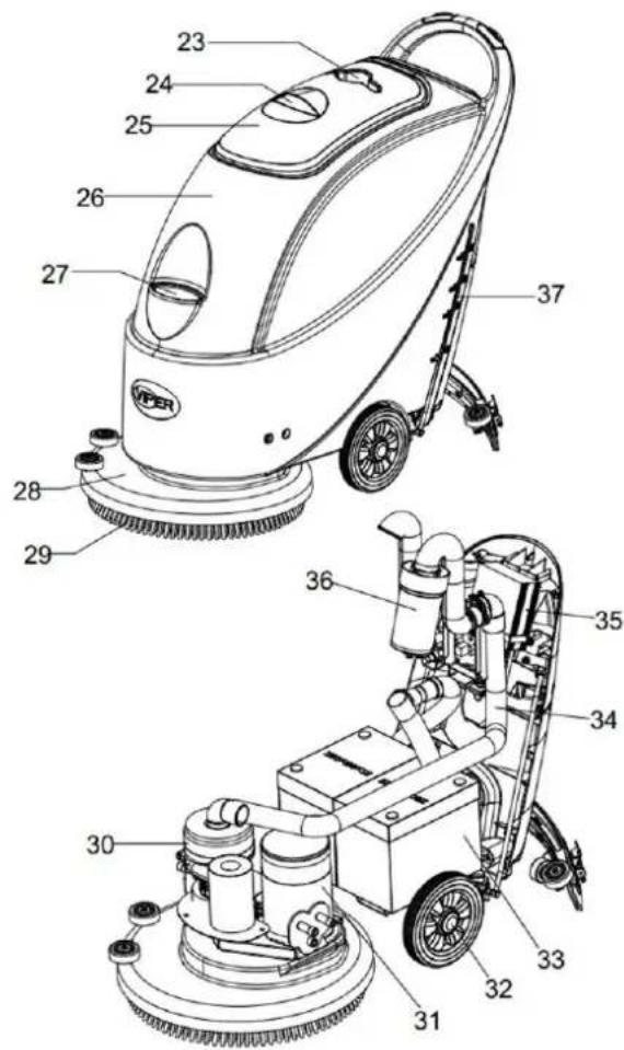
1 pav.
VALDYMO SKYDELIS (2 pav.)
natural_image
Diagram of a folded panel or device with labeled component 'F' (no text or symbols beyond label)natural_image
Technical line drawing of a mechanical device with labeled component 'F' (no text or symbols beyond label)| Akumuliatoriaus tipas / prekės ženklas | Kreivės tipas | SW1 | SW2 | ||
| D1 D2 | D1 D2 | ||||
| WET akumuliatorius | IUIa-ACD | Ijungta | Išjungta | Išjungta | Išjungta |
| Exide-Sonnenschein GEL akumuliatorius | IUIa | Išjungta | Išjungta | ||
| Fullriver AGM akumuliatorius (numatytasis nustatymas) | IUUa | Išjungta | Ijungta | ||
| „Discover“ AGM akumuliatorius | IUIa | Ijungta | Ijungta | ||
AKUMULIATORIAUS MONTAVIMAS IR TIPO NUSTATYMAS (WET ARBA GEL / AGM)
natural_image
Technical line drawings of three different cleaning or cleaning machines (labeled A, B, C) showing internal components and assembly lines without any text or symbols.7 pay.
9 pay.
Tirpalo bako pripildymas

ATSARGIAI!
natural_image
Close-up of hands installing or adjusting a circular device with three buttons (no visible text or symbols)11 pav.
Mašinos išjungimas
15 p av.
ŠEPEČIO / ŠVEITIMO PADO VALYMAS

ATSARGIAI!
16 pav.
TIRPALO FILTRO VALYMAS


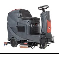
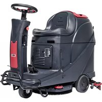
- SЯruЦЦOr UsOr MTBuТГ
- HS430N & HS510N
- EU / UE / EL / EC / EE / ES / EÚ / AB / EG
- Declaration of Conformity
- FC - Floor Scrubber/Sweeper - Battery
- Charging mode: 100-240V; Working mode 24V DC, IP24
- UK Declaration of Conformity
- THNT'A OF IONTANTS
- ΔNTROKUITΔON 2
- MHIPΔNÄ KASIRΔPTΔON 4
- XUΔKA ΓOR USA....6
- MHΔNT'ANHNIA HNK IHRA 13
- TROUNTASPOOTΔNX ....19
- MHIPΔNÄ KΔSPOSHT ....19
- ΔNTROKUITΔON
- NOTA
- PURPOSA
- SPHRA PHRTS HNK MHΔNTANHNIA
- IPHNXAS HNK ΔMPROVAMANTS
- SIOPĂ OΓ HPPTΔΙΗΤΔΟΝ
- ΔΚΑΝΤΔΓΔΙΗΤΔΟΝ ΚΗΤΗ
- UNPHIΣΔNX/TRHNSPORT
- — CHAITAON
- XANARHT SHΓΑΤΑ XUΔΚΑS
- WHRNANX
- MHIPΔN'A K'ASIRΔPTΔON
- IONTROT PHNAT (ГБЕурО2)
- KΔSPTHÄ WΔNKOW OF IPHRXAR ΔNKΔIHTΔON TΔXPT (ΓБЕурО 3)
- (OptБДВТГ, ТрпГБЯТЦГО тД АДПОГs wБтЮ ЦиБГт-БВ ЯЮТеОор)
- XUΔKA FOR USA
- WHRNΔNX
- ΔNSTHTTΔNX HNK SATTΔNX TPA NHTTARÄ OF TPA NAW MHIPΔNA
- b) Without batteries
- Battery charger setting (only for on-board charger if installed)
- Battery charger
- Battery Type Dip-Switches (SPE Charger)
- Battery Type Dip-Switches (Powerfirst Charger)
- INSTALLING BATTERY AND SETTING BATTERY TYPEWET OR GEL/AGM
- ΔBstTΓΓБВЕ ЦТттOrБОs
- ЮТрЕБВЕ тЮО ЦТттOry
- HKOUSTΔNX TPA NHTHNIA OF TPA SQUAAXAA
- SDΓutБДВ tТВЛ МБГГБВЕ
- RAXUTHTΔNX TPA VOTUMA OF WHTAR ΓTOW
- MHIPΔNA STHRT HNK STOP
- StTrtБВЕ tЮО АТЯЮБВО
- MHIPΔNA OPARHTΔON (SIRUNNΔNX HNK KRÄΔNX)
- IHUTΔON!
- РОЯДvOry tТВЛ ОАрtyБВЕ
- ΗΓΤΑR USΔNX TΡΑ MHIPΔΝΑ
- USΔNX ΓOR TPA ΓΔRST TΔM'A
- MHΔNTANHNIA HNK IHRA
- NHTTARĂ IPHRXΔNX
- SQU'AX'AA ITAHNΔNX
- SQU'AX'AA NTHKA IP'AIS HNK RAPTHIAMANT
- NRUSP/POTΔSPΔNX PHK ITAHNΔNX
- IHUTAON!
- WHTAR THNΣ HNK ΓΤΟΗΤ ΓΔΤΑR MΑSP ITAHNΔNX
- SOTUTΔON ΓΔTTAR ITAHNΔNX
- IΔRIUΔT ΓΔXURA OF HS430N HNK HS510N
- ΔNPHTTSVARPAIIPNIS
- AΔNTAΔTUNX 21
- ÜNARNTΔΙΣ ÜNAR KHS NAKΔANΓΑΤΚ (ΗЦЦБГПuBE 2)
- BATTERIEINSTALLATION UND EINSTELLUNG DES BATTERIETYPS (NASS ODER GEL/AGM)
- RAΔNΔXAN VON NÜRSTA/POTΔARPHK
- HIPTUNX!
- RAΔNΔXAN KAS ΓRΔSIPWHSSARTHNΣS
- KASIRΔPTΔON KA TH MHIPΔNA 44
- XUΔKA K'UTΔTΔSHTΔON 46
- ANTRATΔAN AT SOΔN 53
- HVHNT TA KÉMHRRHXA KA TH MHIPΔNA
- ΔNSTHTTAR AT RATΔRAR TA SUPPORT KA NROSSA/PTHTAHU PORTA KΔSQUA
- RAMHRQUA
- HTTANTΔON!
- KÉMHRRHXA AT HRRÊT KA TH MHIPΔNA
- КéАТrrOr ГТ АТЯЮБВО
- NATTOÄAR HVAI TH NROSSÄ/TA PTHTAHU PORTÄ KΔSQUÄ
- HTTANTΔON
- NATTOÄAR TA ΓΔTTRA KA SOTUTΔON
- MΔSA HU RANUT KA TH MHIPΔNA
- N'ASIPRΔOVΔNX VHN KA MHIPΔNA 63
- XΔKS VOOR XANRUΔΣ 65
- ONKARPOUK'AN PORX 73
- PRONTÀAMOPTOSSΔNX ....79
- MHIPΔNA VARWΔOKARAN 79
- ΔNTROKUITΔA
- OPMÁRΣΔNX
- WΔOPΔXΔNXAN AN VARNATARΔNXAN
- NASIPRΔOVΔNX VHN KA MHIPΔNA
- MHIPANA STRUITUUR
- Accutype dipswitches (Powerfirst)
- BATTERIJ INSTALLEREN EN INSTELLING BATTERIJ TYPE (NAT OF GEL / AGM)
- VOOR KA MHIPANA OPSTHRT
- ΔNSTHTTHTΔA'AN TOSMHΣAN VHN KA NORSTAT/PHK POUK'AR
- OPMÄRΣΔNX
- TAT OP!
- РОБВБЕБВЕsАБППОГОВ tТВЛ vuГГОВ
- NORSTAT / POTΔOST PHK RAΔNΔXΔNX
- OPTOSSΔNX ΓΔTTAR RAΔNΔXΔNX
- XUΔKH K'USO 85
- IURH 'A MHNUTANPΔONA ....93
- SIPO KATT'HPPHRAIIPΔO
- PHNNATTO KΔ IONTROTTO (ΓΒΕυτ 2)
- Interruttori DIP per la tipologia di batterie (Powerfirst)
- PRΔMH KΔ HVVΔHRA T'HPPHRAIIPΔO
- ΔNSTHTTHRA 'A KΔSΔNSTHTTHRA TH SPHPPOTH / IUSIΔNATTO
- NOTH
- HTTANPΔONA
- HIIANKARA A SP'AXNARA T'HPPHRAIIPΔO
- НЯЯОВПОrО Г'ТрpTrОЯЯЮБД
- SVUOTHRA ΔT SARNHTOΔO
- KOPO HVAR UTΔTΔPPHTO T'HPPHRAIIPΔO
- USHRA T'HPPHRAIIPΔO PAR TH PRΔMH VOTTH
- IURH 'A MHNUTANPΔONA
- PUTΔTURH KΔ SPHPPOTH/IUSIΔNATTO
- PUTΔPΔH KAT ΓΔTTRO KΔ SOTUPΔONA
- XUÍH PHRH AT MHNAOO ....105
- MHRIPH Ă PHRHKH KA TH MaQUΔNH
- KASPUÉS KA UTΔTΔPHR TH MaQUΔNH
- USHR POR PRΔMÄRH VAP
- TΔMPΔAPH KA TH ASIONΔTTH KA XOMH
- uPRAIHUIDAN!
- XUΔH KA UTΔTΔPHÇβO ....126
- XUΔHS KA S'AXURHNÇH X'ARHT
- Interruptores Dip de tipo de bateria (SPE)
- HPAS UTΔTΔPHR H MaQUΔNH
- UTΔTΔPHÇβO PATH PRΔMΔΔRH VAP
- TΔMPAPH KO SQU'AX'AA
- ΚΑΘΑΡΙΣΜΟΣ ΒΟΥΡΤΣΑΣ / ΜΑΞΙΛΑΡΙΟΥ ΓΥΑΛΙΣΜΑΤΟΣ
- ΠΡΟΣΟΧΗ!
- ΣONTROT PHNATI (ŞOLБГ 2)
- NTtTryTΓTrÜB tTЛÜΓATsÜ
- ΓΔRÇH/PHRTHTMH ΣΑÇASİNİ TAMİPTAMA
- ΚΙΣΣΗΤ!
- SOTÜSÄON ΓİTTRASI TÂMİPTAMA
- POPΔS PŘÍSTROOÃ STOŽANÍ PŘÍSTROOÃ
- OVTÁKHIÍ PHNAT (OЦrázOL 2)
- Mikrospínač typu baterií (Powerfirst)
- MONTÁŽ KRŽÁΣU ΣΗRTÁČA/POKTOŽΣY
- POPNÁMΣH
- ČDŠTĚNÍ ΓΔTTRU NÁKRŽA ČDSTΔIÍPO PROSTŘAKΣU
- DIP - prepínače typov batérií (SPE)
- Nabíjanie batérie
- PRED UVEDENÍM PRÍ9TROJA DO PREVÁDZKY
- MONTÁŽ A DEMONTÁŽ KARTÁČA/UNÁŠAČA PADU
- POZNÁMKA
- Vypnutie stroja
- OBSLUHA PRÍSTROJA (ČISTENIE A VYSÁVANIE)
- ČI9TE6IE KEFY / LEŠTIACEHO 7ADU
- 70ZOR!
- ČI9TENIE FILTRA NÁDRŽE ČI9TIACEHO ROZTOKU
- NUKOWH MHSPĂNĂ - OPNHIPĂNĂH TĂIPNOWA
- PHNAT STAROWHNΔH (Rys.2)
- ZAKŁADANIE I USTAWIENIE TYPU AKUMULATORA (KWASOWE LUB ŻELOWE/AGM)
- NTpOIBBTBBO zC6DrB6LT BT rDztwór
- R'AXUTHIOH PRP'APŁYWU WOKY
- IPYSPIP'ANDA SPIPOTΣΔ/TRPYMHΣH PHK
- OSTROŽNΔA!
- IPYSPIP'ANΔA ΓΔTTRH ROPTWORU MYOAIAXO
- TΔSPTHVÍPSPÚRŐ TΔSPTÍTÁSH
- KOMANΔUT KA UTΔTΔPHRA
- Tip de baterie comutator DIP (SPE)
- Tip de baterie comutator DIP (Powerfirst)
- INSTALAREA BATERIEI ŞI STABILIREA TIPULUI BATERIEIWET SAU CU GEL/AGM
- ΔBstTITrOT ζTtOrББГДr
- HTANTΔA
- KUPĂ UTĂTĂPHRĂH MHȘĂNĂD
- IURĂTHRAH PARΔAΔ/ MHATRΔHTUT KA POTΔSHRA
- IURĂTHRAH ΓΔTTRUTUΔ KA SOTUTΔA
- VOKATO PH UPORHNO....328
- VPKRŽAVHNOĆA ΔN N'AXH 336
- OKPRHVTOHNO'A TAŽHV 342
- OKSTRHNΔTAV NHPRHVA 342
- UVOK
- OPOMNH
- VSANΔNH PRΔROČNΔΣH
- STΔΣΑSASTHVA NHPRHVA
- NHKPORNH PTOŠČH (SΓБЛТ2)
- DIP-stikala tipa akumulatorja (SPE)
- DIP-stikala tipa akumulatorja (Powerfirst)
- NAMEŠČANJE BATERIJE IN DOLOČITEV TIPA BATERIJE (WET ALI GEL/AGM)
- РДГВЬОВЬО ЦТтОрБЬО
- РДГВЬОВЬО rOzOrvДТрЪТ z rTztДрБВД
- ROΣOVHNOA P NHPRHVO (NRΔSHNOA ΔNSUŠANOA)
- ČΔŠČANO'A ΣRTHČA/POTΔRNA NTHPΔNΔIA
- PRAVAKNO!
- ČDŠČANO'A VOKN'AXH RAP'ARVOHROH ΔN MRAŽDI'A PTOVN'AXH ΓΔTTRH
- ČΔŠČANOĆA ΓΔTTRH RHPTOPDNA
- BESKRIVELSE AF MASKINEN 346
- BRUGSGUIDE....348
- VEDLIGEHOLDELSE OG PLEJE 356
- FEJLFINDING 362
- BORTSKAFFELSE AF MASKINEN 362
- INTRODUKTION
- BEMÆRK
- INDHOLDET I DENNE MANUAL
- KONTROLPANEL (Figur 2)
- Batteritypens DIP-Switches (Powerfirst)
- INSTALLATION AF BATTERIER OG INDSTILLING AF BATTERITYPE (WET ELLER GEL/AGM)
- At slukke maskinen
- DRIFT AF MASKINEN (RENG∅RING OG T∅RRING)
- KONTROL OG UDSKIFTNING AF GUMMISKRABER
- RENG∅RING AF B∅RSTE/POLERINGSPUDE
- FORSIGTIG!
- RENG∅RING AF OPL∅SNINGSFILTER
- INNEHÅLLSFÖRTECKNING
- INLEDNING 364
- MASKINBESKRIVNING 366
- KONTROLLPANEL (figur 2)
- Batterityp DIP-switchar (Powerfirst)
- BATTERIINSTALLATION OCH INSTÄLLNING AV BATTERITYP (WET ELLER GEL/AGM)
- MASKINDRIFT (RENGÖRING OCH TORKNING)
- RENGÖRING AV BORSTE/POLERINGSDYNA
- FÖRSIKTIGHET!
- RENGÖRING AV LÖSNINGSFILTER
- FEILS∅KING 402
- AVHENDING AV MASKINEN....402
- INNLEDNING
- MERK
- BETJENINGSPANEL (figur 2)
- BATTERIINNSTALLASJON OG BATTERITYPEINNSTILLING (WET ELLER GEL/AGM)
- Fylling av vanntank
- FORSIKTIG!
- Slå av maskinen
- MASKINDRIFT (SKURING OG T∅RKING)
- RENGJ∅RING AV B∅RSTE/PAD-HOLDER
- RENGJ∅RING AV VANNFILTER
- Liuossäilion täyttö
- VAARA!
- Kytke kone pois
- HARJAN/KIILLOTUSTYYNYN PUHDISTAMINEN
- LIUOSSUODATTIMEN PUHDISTAMINEN
- Male (DIP) sklopke za određenu vrstu akumulatora (SPE)
- Male (DIP) sklopke za određenu vrstu akumulatora (Powerfirst)
- UGRADNJA BATERIJE I POSTAVKA TIPA BATERIJE (WET ILI GEL / AGM)
- Punjenje baterije
- PRIJE POČETKA RADA STROJA
- UGRADNJA I SKIDANJE DRŽAČA ČETKE / ULOŠKA
- BILJEŠKA
- Punjenje spremnika otopine
- OPREZ!
- REGULIRANJE VOLUMENA PROTOKA VODE
- UPOZORENJE!
- ČIŠĆENJE ČETKE / ULOŠKA
- ČIŠĆENJE FILTRA OTOPINE
- ÜLDISED OHUTUSJUHISED
- JUHTPANEEL (joonis 2)
- A
- AKU AI ALDA INE JA AKUT I SEADISTA INE R V I EEL A AKUD
- ETTEVAATUST
- HARJA/POLEERPADJA PUHASTAMINE
- ETTEVAATUST!
- ESUVA ENDI ILTRI U ASTA INE
- AKUMULATORA UZSTĀDĪŠANA UN AKUMULATORA TIPA IESTATĪŠANA (WET VAI GEL/AGM)
- Škīduma tvertnes uzpilde
- UZMANIBU!
- Iekārtas izslēgšana
- SUKAS/PULĒŠANAS PALIKNA TĪRĪŠANA
- ŠKĪDUMA FILTRA TĪRĪŠANA
- MAŠINOS APRAŠYMAS 484
- NAUDOJIMO INSTRUKCIJA....486
- PRIEŽIŪRA 493
- GEDIMU PAIEŠKA IR ŠALINIMAS 499
- MAŠINOS UTILIZAVIMAS 499
- IŽANGA
- PASTABA
- VALDYMO SKYDELIS (2 pav.)
- AKUMULIATORIAUS MONTAVIMAS IR TIPO NUSTATYMAS (WET ARBA GEL / AGM)
- Tirpalo bako pripildymas
- ATSARGIAI!
- Mašinos išjungimas
- ŠEPEČIO / ŠVEITIMO PADO VALYMAS
- TIRPALO FILTRO VALYMAS
Brand : NILFISK
Model : Viper AS430
Category : Sweeper